JP2018517864A - Lock cylinder with replaceable key with enhanced torque resistance - Google Patents
Lock cylinder with replaceable key with enhanced torque resistanceDownload PDFInfo
- Publication number
- JP2018517864A JP2018517864AJP2017565266AJP2017565266AJP2018517864AJP 2018517864 AJP2018517864 AJP 2018517864AJP 2017565266 AJP2017565266 AJP 2017565266AJP 2017565266 AJP2017565266 AJP 2017565266AJP 2018517864 AJP2018517864 AJP 2018517864A
- Authority
- JP
- Japan
- Prior art keywords
- key
- locking bar
- lock cylinder
- cylinder body
- groove
- Prior art date
- Legal status (The legal status is an assumption and is not a legal conclusion. Google has not performed a legal analysis and makes no representation as to the accuracy of the status listed.)
- Granted
Links
Images


Classifications
- E—FIXED CONSTRUCTIONS
- E05—LOCKS; KEYS; WINDOW OR DOOR FITTINGS; SAFES
- E05B—LOCKS; ACCESSORIES THEREFOR; HANDCUFFS
- E05B27/00—Cylinder locks or other locks with tumbler pins or balls that are set by pushing the key in
- E05B27/0082—Side bar locking
- E—FIXED CONSTRUCTIONS
- E05—LOCKS; KEYS; WINDOW OR DOOR FITTINGS; SAFES
- E05B—LOCKS; ACCESSORIES THEREFOR; HANDCUFFS
- E05B15/00—Other details of locks; Parts for engagement by bolts of fastening devices
- E05B15/04—Spring arrangements in locks
- E—FIXED CONSTRUCTIONS
- E05—LOCKS; KEYS; WINDOW OR DOOR FITTINGS; SAFES
- E05B—LOCKS; ACCESSORIES THEREFOR; HANDCUFFS
- E05B27/00—Cylinder locks or other locks with tumbler pins or balls that are set by pushing the key in
- E05B27/0003—Details
- E05B27/0017—Tumblers or pins
- E—FIXED CONSTRUCTIONS
- E05—LOCKS; KEYS; WINDOW OR DOOR FITTINGS; SAFES
- E05B—LOCKS; ACCESSORIES THEREFOR; HANDCUFFS
- E05B27/00—Cylinder locks or other locks with tumbler pins or balls that are set by pushing the key in
- E05B27/0003—Details
- E05B27/0017—Tumblers or pins
- E05B27/0021—Tumblers or pins having movable parts
- E—FIXED CONSTRUCTIONS
- E05—LOCKS; KEYS; WINDOW OR DOOR FITTINGS; SAFES
- E05B—LOCKS; ACCESSORIES THEREFOR; HANDCUFFS
- E05B27/00—Cylinder locks or other locks with tumbler pins or balls that are set by pushing the key in
- E05B27/005—Cylinder locks or other locks with tumbler pins or balls that are set by pushing the key in with changeable combinations
- E—FIXED CONSTRUCTIONS
- E05—LOCKS; KEYS; WINDOW OR DOOR FITTINGS; SAFES
- E05B—LOCKS; ACCESSORIES THEREFOR; HANDCUFFS
- E05B27/00—Cylinder locks or other locks with tumbler pins or balls that are set by pushing the key in
- E05B27/0057—Cylinder locks or other locks with tumbler pins or balls that are set by pushing the key in with increased picking resistance
- E—FIXED CONSTRUCTIONS
- E05—LOCKS; KEYS; WINDOW OR DOOR FITTINGS; SAFES
- E05B—LOCKS; ACCESSORIES THEREFOR; HANDCUFFS
- E05B29/00—Cylinder locks and other locks with plate tumblers which are set by pushing the key in
- E05B29/004—Cylinder locks and other locks with plate tumblers which are set by pushing the key in with changeable combinations
- E—FIXED CONSTRUCTIONS
- E05—LOCKS; KEYS; WINDOW OR DOOR FITTINGS; SAFES
- E05B—LOCKS; ACCESSORIES THEREFOR; HANDCUFFS
- E05B29/00—Cylinder locks and other locks with plate tumblers which are set by pushing the key in
- E05B29/0066—Side bar locking
Landscapes
- Physics & Mathematics (AREA)
- Electromagnetism (AREA)
- Lock And Its Accessories (AREA)
- Quick-Acting Or Multi-Walled Pipe Joints (AREA)
- Mutual Connection Of Rods And Tubes (AREA)
- Details Of Connecting Devices For Male And Female Coupling (AREA)
- Preventing Unauthorised Actuation Of Valves (AREA)
Abstract
Translated fromJapaneseDescription
Translated fromJapanese 関連出願
本出願は、全体が参照により本明細書に組込まれている2015年6月16日出願の米国仮特許出願第62/180,339号及び2016年6月3日出願の米国特許出願第15/172,206号の利益を主張するものである。RELATED APPLICATIONS This application is a U.S.
本開示は、概して錠前に関する。詳細には、本開示は、トルク抵抗が増強された鍵付替え可能(rekeyable)なロックシリンダを伴う錠前に関する。 The present disclosure relates generally to locks. In particular, the present disclosure relates to a lock with a rekeyable lock cylinder with enhanced torque resistance.
シリンダプラグを取外すことなく鍵を付替えできるロックシリンダが公知である。例えば、米国特許第8,033,150号は、鍵付替え可能なロックシリンダについて記載している。このタイプの錠前は、錠前師を使用することなく容易に鍵を付替えできることから、消費者にとって、メリットが大きい。 A lock cylinder is known in which the key can be changed without removing the cylinder plug. For example, U.S. Pat. No. 8,033,150 describes a lock cylinder that can be re-keyed. This type of lock has great merit for consumers because the key can be easily changed without using a locksmith.
プラグシリンダは、許可された鍵が鍵穴に挿入された場合に自由に回転すべきであるが、ロックシリンダは、無許可の鍵(又は他の物体)によりトルクが加えられた場合に、プラグの回転に抵抗するように構成されていなければならない。ロックシリンダの大きなトルク抵抗が、不法進入を減少させるための秘訣である。したがって、トルク抵抗が増強された鍵付替え可能な錠前に対するニーズが存在する。 The plug cylinder should be free to rotate when an authorized key is inserted into the keyhole, but the lock cylinder should be plugged in when the torque is applied by an unauthorized key (or other object). Must be configured to resist rotation. The large torque resistance of the lock cylinder is the secret to reducing illegal entry. Accordingly, there is a need for a lockable lock with increased torque resistance.
一態様によると、本開示は、シリンダ本体及びプラグアセンブリを伴う鍵付替え可能なロックシリンダを提供する。シリンダ本体は、長手方向軸を画定し、且つ、溝を含む。プラグアセンブリは、シリンダ本体内に配置され、且つ、長手方向軸を中心に回転可能である。ロックシリンダは、プラグアセンブリ内に配置された複数のキーフォロワ及び対応する複数のラックを含む。複数のラックのうちの少なくとも1つは、新しい鍵への鍵の付替えを容易にするために、鍵付替え可能なロックシリンダ内に挿入された物体による力の適用に応じて、複数のキーフォロワのうちの少なくとも1つから選択的に係合解除可能である。ロックシリンダは、無許可の物体を用いた鍵付替え可能なロックシリンダの開錠を防ぐために、シリンダ本体に対するプラグアセンブリの回転を阻止するための手段を含む。いくつかの実施形態において、阻止用手段は、無許可の物体を用いたプラグアセンブリのトルク付加が、複数のラックに力を伝達することなく、阻止用手段に対して力が適用されるように構成されている。このタイプの構成は、ロックシリンダのトルク抵抗を増強させる。 According to one aspect, the present disclosure provides a keyable lock cylinder with a cylinder body and a plug assembly. The cylinder body defines a longitudinal axis and includes a groove. The plug assembly is disposed within the cylinder body and is rotatable about a longitudinal axis. The lock cylinder includes a plurality of key followers and a corresponding plurality of racks disposed within the plug assembly. At least one of the plurality of racks includes a plurality of key followers in response to application of force by an object inserted in the lockable lock cylinder to facilitate reassignment of keys to new keys. Can be selectively disengaged from at least one of them. The lock cylinder includes means for preventing rotation of the plug assembly relative to the cylinder body to prevent unlocking of the lockable lock cylinder using an unauthorized object. In some embodiments, the blocking means is such that torque application of the plug assembly using an unauthorized object applies the force to the blocking means without transmitting the force to multiple racks. It is configured. This type of configuration increases the torque resistance of the lock cylinder.
いくつかの実施形態において、阻止用手段は、長手方向軸に対して横断方向に、シリンダ本体の溝内へ入る施錠位置とシリンダ本体の溝から出る開錠位置との間で可動である、少なくとも1つのロッキングバーを含んでいる。例えば、ロッキングバーは、施錠位置にある場合に溝の表面と係合する表面を含むことができる。いくつかの例示的実施形態において、ロッキングバーが施錠位置にある場合に係合する少なくとも1つのロッキングバー及び溝のそれぞれの表面は、おおよそ平行な平面内にある。状況に応じて、ロッキングバーが施錠位置にある場合にシリンダ本体内の溝と係合する少なくとも1つのロッキングバーの表面は、傾斜した表面でない。例えばこの表面は、平坦であることができる。いくつかのケースにおいて、ロッキングバーの縁部は実質的に方形にされており、例えば、おおよそ矩形の断面を有する。 In some embodiments, the blocking means is at least movable between a locked position entering the groove in the cylinder body and an unlocked position exiting from the groove in the cylinder body, transverse to the longitudinal axis. Includes one locking bar. For example, the locking bar can include a surface that engages the surface of the groove when in the locked position. In some exemplary embodiments, the respective surfaces of the at least one locking bar and the groove that engage when the locking bar is in the locked position are in approximately parallel planes. Depending on the situation, the surface of the at least one locking bar that engages the groove in the cylinder body when the locking bar is in the locked position is not an inclined surface. For example, the surface can be flat. In some cases, the edge of the locking bar is substantially square, for example, having a generally rectangular cross section.
いくつかの実施形態においては、ロッキングバーを複数のラックに向けて推し進める1つ以上の付勢用部材が存在する。この構成では、付勢用部材は、許可された鍵が鍵穴に挿入された場合に、ロッキングバーをシリンダ本体内の溝から外に出るように推し進める。いくつかの例示的実施形態においては、付勢用部材のバネ力は、バネ式キーフォロワのバネ力よりも小さい。したがって、バネ式キーフォロワは、鍵が鍵穴の中に挿入されていない場合、付勢用部材のバネ力を克服して、ロックシリンダを施錠することになる。 In some embodiments, there are one or more biasing members that push the locking bar toward the racks. In this configuration, the biasing member pushes the locking bar out of the groove in the cylinder body when the authorized key is inserted into the keyhole. In some exemplary embodiments, the spring force of the biasing member is less than the spring force of the spring key follower. Therefore, the spring type key follower locks the lock cylinder by overcoming the spring force of the biasing member when the key is not inserted into the keyhole.
本開示のさらなる特徴及び利点は、現在認識されている本開示の最良の実施形態を例証する以下の詳細な説明を考慮した時点で、当業者には明白になるであろう。 Additional features and advantages of the present disclosure will become apparent to those skilled in the art in view of the following detailed description illustrating the best mode of the presently recognized disclosure.
本開示について、以下で、非限定的な実施例として提供される添付図面を参照しながら説明する。 The present disclosure will now be described with reference to the accompanying drawings provided as non-limiting examples.
対応する参照文字は、複数の図全体を通して、対応する部品を示す。本明細書中で提示する例証は、1つの形での本発明の実施を例示しており、このような例証は、いかなる形であれ本発明の範囲を限定するものとみなされるべきではない。 Corresponding reference characters indicate corresponding parts throughout the several views. The illustrations presented herein illustrate the practice of the invention in one form and such illustration should not be construed as limiting the scope of the invention in any way.
本開示は、シリンダプラグを取外すことなく鍵の付替え(rekeyed)をすることができる、鍵付替え可能(rekeyable)なロックシリンダに関する。ロックシリンダの鍵を付替えするための作業は、参照により本明細書に組込まれている米国特許第8,033,150号中に記載のものと類似している。鍵を付替える作業は類似の形で機能するものの、当該ロックシリンダは、増強されたトルク抵抗を含んでいる。いくつかの実施形態において、この増強されたトルク抵抗は、プラグシリンダ上のトルクをラックから隔離するように構成され、こうしてロックシリンダの耐久性が増大している。 The present disclosure relates to a rekeyable lock cylinder that can be rekeyed without removing a cylinder plug. The operation for changing the lock cylinder key is similar to that described in US Pat. No. 8,033,150, which is incorporated herein by reference. Although the operation of changing the key functions in a similar manner, the lock cylinder includes an increased torque resistance. In some embodiments, this increased torque resistance is configured to isolate the torque on the plug cylinder from the rack, thus increasing the durability of the lock cylinder.
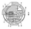
本開示の一実施形態に係る例示的ロックシリンダ10が図1及び図2に例示されている。ロックシリンダ10は、長手方向軸12、シリンダ本体14、及び、プラグアセンブリ16を含む。リテーナークリップ18(図2)が、シリンダ本体14とプラグアセンブリ16とを結合させている。 An
図2を見れば最も良く分かるように、シリンダ本体14は、実例として、前方端部22、後方端部24及び内部表面28を画定するシリンダ壁26を有する、概して円筒形の本体20を含む。シリンダ壁26は、内部のロッキングバー係合用溝30(図4、図5、図6を見れば最も良く分かる)を含む。いくつかの実施形態において、ロッキングバー係合用溝30は、概して矩形形状の断面を有し、シリンダ本体14の一部分に沿って長手方向に、典型的には前方端部22から延在する。 As best seen in FIG. 2, the
プラグアセンブリ16は、プラグ本体32、キャリアサブアセンブリ34及び複数のバネ式ピン38(キーフォロワとも呼ばれる)を含む。プラグ本体32は、実例として、プラグ面36、中間部分40及び駆動部分42を含む。プラグ面36は、鍵穴開口部44、鍵付替え工具用開口部46、及び、ドリリング防止用玉軸受50を収容するために半径方向外向きに延在する一対のチャネル48、を画定する。駆動部分42は、ラッチアセンブリ(図示せず)と結合され得るトルクブレード51を駆動するように構成されている。駆動部分42は、さらに、その周囲に形成された一対のスロット52と、シリンダ本体14内にプラグ本体32を保持する目的でリテーナークリップ18を収容するための中央溝54と、を含む。 The
中間部分40は、シリンダ区分として形成され且つバネ式ピン38を収容するための複数のチャネル58を有する、主要部分56を含む。チャネル58は、実例として、プラグ本体32の長手方向軸に対し横断方向に延在する。平面的表面60が、保持キャップ64を収容するための陥凹62を画定している。チャネル58は、その側壁が平面的表面66に向って開放している状態で、プラグ本体32内に部分的に延在している。平面的表面66は、実例として、複数の弾丸型のラック係合用機能部68を含む。 The
キャリアサブアセンブリ34は、キャリヤ70、複数のラック72、バネキャッチ73、ロッキングバー74、ロッキングバー74をラック72に向って推し進めるようロッキングバー74に接して対応する付勢用部材78を保持するための一対のクリップ76、及び、戻しバネ80を含む。キャリヤ70は、キャリヤ70と主要部分56とが組合わさって、シリンダ本体14の内側に適合するシリンダを形成するように、プラグ本体32の主要部分56と相補的であるシリンダ区分の形をした本体82を含む。キャリヤ70は、湾曲した表面84及び平坦な表面86を含む。湾曲表面84は、ロッキングバースロット88、バネキャッチ陥凹90、及び、クリップ76を収容するための一対のクリップ収容用陥凹100、を含む。ロッキングバースロット88は、実例として、付勢用部材78を収容するための一対の付勢用部材収容用中ぐり92を含む。示された実施形態において、ロッキングバー74は、付勢用部材78を収容するための対応する一対の陥凹部域96を含む。 The
バネ式ロッキングバー74は、キャリヤ70内のロッキングバースロット88に適合するようにサイズ決定され、構成される。ロッキングバー74は、実例として、施錠位置にある場合(図5及び図6)にシリンダ本体14内のロッキングバー係合用溝30内に収容され開錠位置(図4)にある場合にロッキングバー係合用溝30から外へと延在する、阻止用部分98を含んでいる。いくつかの実施形態において、実例として示されているように、阻止用部分98は、矩形の断面を形成する、方形にされた縁部を有する。この方形にされた表面は、カム作用を介してシリンダ本体内の溝から外に移動する米国特許第8,033,150号中に記載のロッキングバーの三角形状の縁部と好対照をなす。シリンダ本体14内の溝30から外に阻止用部分98を移動させるために、付勢用部材78による推進を用いることによって、方形にされた縁部をロッキングバー係合用溝30内の対応する平坦な表面と共に使用することができ、これによって、米国特許第8,033,150号に記載の三角形状の縁部及び対応する三角形状のロッキングバー係合用溝に比較して、ロックシリンダ10のトルク抵抗を増大させることができる。その上、こうして、無許可の鍵(又は他の物体)によって適用されるトルクはカム作用を介してロッキングバー74からラック72に伝達されないことから、ラック72上の応力は軽減される。その代り、ロッキングバー係合用溝30とのロッキングバー74の界面が、このトルクをラック72から隔離する。阻止用部分98の方形にされた縁部の反対側に、ロッキングバー74は、ラック72内に形成されたロッキングバー係合用溝104と係合するように構成されたフランジ102を含んでいる(図4、図5、図6)。キャリヤ70の平担な表面86は、キャリヤ70の長手方向軸に垂直に延在する、複数の平行なラック収容用スロット94を含む。 Spring-loaded
図3は、クリップ76の1つを横断方向に切断したロックシリンダ10の例示的断面図である。この図においては、クリップ76がキャリヤ70の周りに延在していることが分かる。付勢用部材78の一方の端部は、クリップ76の収容用部分106に接して固定されており、もう一方の端部は、ロッキングバー74の陥凹部域96内に収容されロッキングバー74をラック72に対し推し進める。この実施形態において、ロッキングバー74は、付勢用部材78によってラック72に対して継続的に推し進められる。 FIG. 3 is an exemplary cross-sectional view of the
図4、5及び図6は、ロッキングバー74の阻止用部分98に沿って横断方向に切断したロックシリンダ10の例示的断面図である。鍵穴開口部44内に挿入された許可された鍵108を示す図4において、許可された鍵108の鍵山は、ロッキングバー74のフランジ102が付勢用部材78による推し進めを介してラック72のそれぞれのロッキングバー係合用溝104内に収容される位置まで、バネ式ピン38ひいてはラック72を移動させるようなものである。これにより、ロッキングバー74の阻止用部分98は、ロッキングバー係合用溝30から出てその開錠位置に位置づけされ、こうして、ロックシリンダ10を開錠するためのシリンダ本体14に対するプラグアセンブリ16の自由な回転が可能になる。ロッキングバー74をロッキングバー係合用溝30から外に推し進めるためのこの付勢用部材78の使用は、米国特許第8,033,150号中に記載のシリンダ本体内の溝から外にロッキングバーを移動させるためのカム作用と好対照をなす。図5は、無許可の鍵110が鍵穴開口部44内に挿入されている一実施例を例示する。無許可の鍵110の鍵山は「無許可のもの」であることから、少なくとも1つのラック72のロッキングバー係合用溝104は、ロッキングバー74のフランジ102と整列しない。したがって、ロッキングバー104は、シリンダ本体14のロッキングバー係合用溝30から外に推し進められることができず、このことはすなわち、阻止用部分98がシリンダ本体14に対するプラグアセンブリ16の回転を防ぐことを意味している。図示された実施形態では、阻止用部分98の縁部は方形にされており、シリンダ本体14のロッキングバー係合用溝30は対応する形状を有する。このことはすなわち、シリンダ本体14に対するプラグアセンブリ16のトルク付加によってひき起こされる力が、ロッキングバー係合用溝30の平担な内部表面114に対して、阻止用部分98の平坦な表面112に適用される、ということを意味する。表面112、114は、相互に平坦であることから、こうして、米国特許第8,033,150号のロッキングバーの三角形縁部及びシリンダ本体の対応する三角形縁部などの傾斜した表面と比べて、トルク抵抗は、増大する。その上、平坦な表面112、114とは異なり、米国特許第8,033,150号中に記載の傾斜した表面は、一部のケースではラックを変形させるか又は他の形でラックの耐久性を減少させる可能性のある力をラックに加えるカム作用を作り出す。図6は、ロックシリンダ10内に全く鍵が存在しない一実施例を例示している。バネ式ピン38のバネは、付勢用部材78よりも高いバネ力を有する。したがって、鍵穴内に鍵が無い場合、バネ式ピン38は、ラック72を下向きに駆動し付勢用部材78の力を克服し、こうして、ロッキングバー74のフランジ102はラック74のロッキングバー係合用溝104の中に収容されない。これにより、ロッキングバー74の阻止用部分98は、シリンダ本体14のロッキングバー係合用溝30内に強制され、こうして、シリンダ本体14に対するプラグアセンブリ16の回転は妨げられる。 4, 5 and 6 are exemplary cross-sectional views of the
以下では、本明細書中で開示されている鍵付替え可能なロックシリンダの例示的実施例を提供する。鍵付替え可能なロックシリンダの一実施形態は、以下に説明される実施例のいずれか1つ以上及びそのいずれかの組合せを含んでよい。 The following provides an exemplary embodiment of the key-changeable lock cylinder disclosed herein. One embodiment of a lockable lock cylinder may include any one or more of the examples described below and any combination thereof.
実施例1は、長手方向軸を有し溝を含むシリンダ本体を伴う鍵付替え可能なロックシリンダである。ロックシリンダは、長手方向軸を中心にして回転可能であるシリンダ本体中に配置されたプラグアセンブリを含む。対応する複数のラックを伴う複数のキーフォロワがプラグアセンブリ内に配置されている。複数のラックのうちの少なくとも1つは、新しい鍵への鍵の付替えを容易にするために、鍵付替え可能なロックシリンダ内に挿入された物体による力の適用に応じて、複数のキーフォロワのうちの少なくとも1つから選択的に係合解除可能である。ロックシリンダは、無許可の物体を用いた鍵付替え可能なロックシリンダの開錠を防ぐために、シリンダ本体に対するプラグアセンブリの回転を阻止するための手段を含む。阻止用手段は、無許可の物体を用いたプラグアセンブリのトルク付加に由来する力が、複数のラックに伝達されるあらゆる力に比較した場合に主としてシリンダ本体と阻止用手段との間で分配され、こうして鍵付替え可能なロックシリンダのトルク抵抗を増強させるように、構成されている。 Example 1 is a lock cylinder with a key changeable with a cylinder body having a longitudinal axis and including a groove. The lock cylinder includes a plug assembly disposed in a cylinder body that is rotatable about a longitudinal axis. A plurality of key followers with a corresponding plurality of racks are disposed in the plug assembly. At least one of the plurality of racks includes a plurality of key followers in response to application of force by an object inserted in the lockable lock cylinder to facilitate reassignment of keys to new keys. Can be selectively disengaged from at least one of them. The lock cylinder includes means for preventing rotation of the plug assembly relative to the cylinder body to prevent unlocking of the lockable lock cylinder using an unauthorized object. The blocking means is mainly distributed between the cylinder body and the blocking means when the force resulting from the torque application of the plug assembly using unauthorized objects is compared to any force transmitted to the racks. In this way, the torque resistance of the lock cylinder that can be re-keyed is increased.
実施例2において、実施例1の主題はさらに、阻止用手段が、長手方向軸に対して横断方向に、シリンダ本体の溝内へ入る施錠位置とシリンダ本体の溝から出る開錠位置との間で可動である、少なくとも1つのロッキングバーを含むように構成されている。 In Example 2, the subject matter of Example 1 further includes a blocking means between the locking position entering the cylinder body groove and the unlocking position exiting the cylinder body groove, transverse to the longitudinal axis. And is configured to include at least one locking bar that is movable.
実施例3において、実施例2の主題はさらに、少なくとも1つのロッキングバーが、施錠位置にある場合に、溝の表面と係合する表面を含むように構成されている。少なくとも1つのロッキングバーが施錠位置にある場合に係合する、少なくとも1つのロッキングバー及び溝のそれぞれの表面が、おおよそ平行な平面内にある。 In Example 3, the subject of Example 2 is further configured to include a surface that engages the surface of the groove when at least one locking bar is in the locked position. Each surface of the at least one locking bar and the groove that engages when the at least one locking bar is in the locked position is in a generally parallel plane.
実施例4において、実施例3の主題はさらに、少なくとも1つのロッキングバーが施錠位置にある場合に、シリンダ本体内の溝と係合する少なくとも1つのロッキングバーの表面が、傾斜した表面でないように構成されている。 In Example 4, the subject matter of Example 3 further ensures that when at least one locking bar is in the locked position, the surface of at least one locking bar that engages the groove in the cylinder body is not an inclined surface. It is configured.
実施例5において、実施例3の主題はさらに、少なくとも1つのロッキングバーが施錠位置にある場合に、シリンダ本体内の溝と係合する少なくとも1つのロッキングバーの表面が、平坦な表面であるように構成されている。 In Example 5, the subject matter of Example 3 further provides that when at least one locking bar is in the locked position, the surface of the at least one locking bar that engages the groove in the cylinder body is a flat surface. It is configured.
実施例6において、実施例3の主題はさらに、シリンダ本体内の溝と係合する少なくとも1つのロッキングバーの表面が、長手方向軸に対して半径方向の軸におおよそ平行である平面内にあるように構成されている。 In Example 6, the subject of Example 3 is further that the surface of at least one locking bar that engages a groove in the cylinder body lies in a plane that is approximately parallel to the radial axis relative to the longitudinal axis. It is configured as follows.
実施例7において、実施例2の主題はさらに、施錠位置にある場合に、少なくとも1つのロッキングバーの縁部が、シリンダ本体の溝の中に収容されるように構成されている。 In Example 7, the subject of Example 2 is further configured such that the edge of at least one locking bar is received in a groove in the cylinder body when in the locked position.
実施例8において、実施例7の主題はさらに、少なくとも1つのロッキングバーの縁部が、実質的に方形であるように構成されている。 In Example 8, the subject matter of Example 7 is further configured such that the edge of at least one locking bar is substantially square.
実施例9において、実施例7の主題はさらに、少なくとも1つのロッキングバーの縁部が、おおよそ矩形の断面を有するように構成されている。 In Example 9, the subject of Example 7 is further configured such that the edge of at least one locking bar has a generally rectangular cross-section.
実施例10において、実施例1の主題はさらに、阻止用手段を複数のラックに向けて推し進める付勢用部材を含むように構成されている。 In Example 10, the subject matter of Example 1 is further configured to include a biasing member that pushes the blocking means toward the plurality of racks.
実施例11において、実施例10の主題はさらに、複数のキーフォロワがバネ式であり、いずれのキーフォロワも少なくとも1つのロッキングバーによって持ち上げられないように保証するために、付勢用部材のバネ力が、バネ式キーフォロワのバネ力に比例するように構成されている。 In Example 11, the subject of Example 10 is further that the plurality of key followers are spring-loaded, and the spring force of the biasing member is to ensure that none of the key followers are lifted by at least one locking bar. It is configured to be proportional to the spring force of the spring type key follower.
実施例12は、溝を含む長手方向軸を伴うシリンダ本体を含む、鍵付替え可能なロックシリンダである。ロックシリンダは、シリンダ本体内に配置され長手方向軸を中心に回転可能なプラグアセンブリを含む。複数のラックと少なくとも1つのロッキングバーとを含む、キャリアアセンブリが提供される。ロックシリンダは、プラグアセンブリ内に配置された複数のキーフォロワを含む。複数のラックのうちの少なくとも1つは、新しい鍵への鍵の付替えを容易にするために、鍵付替え可能なロックシリンダ内に挿入された物体による力の適用に応じて、複数のキーフォロワのうちの少なくとも1つから選択的に係合解除可能である。少なくとも1つのロッキングバーは、長手方向軸に対して横断方向に及び長手方向軸を中心にして回転的に可動である。少なくとも1つのロッキングバーの少なくとも一部分は、シリンダ本体の溝内へ入る施錠位置とシリンダ本体内の溝から出る開錠位置との間で可動である。少なくとも1つのロッキングバーは、無許可の物体を用いた鍵付替え可能なロックシリンダの開錠を防ぐように構成されている。少なくとも1つのロッキングバーは、無許可の物体を用いたプラグアセンブリのトルク付加に由来する力が、複数のラックに対し伝達されるあらゆる力に比較した場合に、主としてシリンダ本体とキャリアアセンブリとの間で分配されるように構成されている。 Example 12 is a lockable lock cylinder that includes a cylinder body with a longitudinal axis that includes a groove. The lock cylinder includes a plug assembly disposed within the cylinder body and rotatable about a longitudinal axis. A carrier assembly is provided that includes a plurality of racks and at least one locking bar. The lock cylinder includes a plurality of key followers disposed within the plug assembly. At least one of the plurality of racks includes a plurality of key followers in response to application of force by an object inserted in the lockable lock cylinder to facilitate reassignment of keys to new keys. Can be selectively disengaged from at least one of them. The at least one locking bar is movable in a direction transverse to the longitudinal axis and about the longitudinal axis. At least a portion of the at least one locking bar is movable between a locked position that enters the groove in the cylinder body and an unlocked position that exits from the groove in the cylinder body. At least one locking bar is configured to prevent unlocking of a lockable lock cylinder using an unauthorized object. The at least one locking bar is primarily between the cylinder body and the carrier assembly when the force resulting from the torque application of the plug assembly using unauthorized objects is compared to any force transmitted to the racks. It is configured to be distributed with.
実施例13において、実施例12の主題はさらに、付勢用部材が、少なくとも1つのロッキングバーを複数のラックに向けて推し進めるように構成されている。 In Example 13, the subject matter of Example 12 is further configured such that the biasing member pushes at least one locking bar toward the plurality of racks.
実施例14において、実施例12の主題はさらに、複数のキーフォロワがバネ式であり、付勢用部材のバネ力がバネ式キーフォロワのバネ力よりも小さいように構成されている。 In the fourteenth embodiment, the subject of the twelfth embodiment is further configured such that the plurality of key followers are spring-type, and the spring force of the biasing member is smaller than the spring force of the spring-type key follower.
実施例15は、溝を含む長手方向軸を伴うシリンダ本体を含む鍵付替え可能なロックシリンダである。プラグアセンブリが、シリンダ本体内に配置され、且つ、長手方向軸を中心に回転可能である。ロックシリンダは、プラグアセンブリ内に配置された複数のキーフォロワ及び対応する複数のラックを含む。複数のラックのうちの少なくとも1つは、新しい鍵への鍵の付替えを容易にするために、鍵付替え可能なロックシリンダ内に挿入された物体による力の適用に応じて、複数のキーフォロワのうちの少なくとも1つから選択的に係合解除可能である。少なくとも1つのロッキングバーが、長手方向軸に対し横断方向に及び長手方向軸を中心にして回転的に可動である。少なくとも1つのロッキングバーの少なくとも一部分は、シリンダ本体の溝内へ入る施錠位置とシリンダ本体内の溝から出る開錠位置との間で可動である。構内に収容される少なくとも1つのロッキングバーの部分は、おおよそ矩形の断面を有している。ロックシリンダは、少なくとも1つのロッキングバーを複数のラックに向って推し進める付勢用部材を含む。 Example 15 is a lockable lock cylinder that includes a cylinder body with a longitudinal axis that includes a groove. A plug assembly is disposed within the cylinder body and is rotatable about a longitudinal axis. The lock cylinder includes a plurality of key followers and a corresponding plurality of racks disposed within the plug assembly. At least one of the plurality of racks includes a plurality of key followers in response to application of force by an object inserted in the lockable lock cylinder to facilitate reassignment of keys to new keys. Can be selectively disengaged from at least one of them. At least one locking bar is movable in a direction transverse to the longitudinal axis and about the longitudinal axis. At least a portion of the at least one locking bar is movable between a locked position that enters the groove in the cylinder body and an unlocked position that exits from the groove in the cylinder body. The portion of the at least one locking bar housed on the premises has an approximately rectangular cross section. The lock cylinder includes a biasing member that pushes at least one locking bar toward the plurality of racks.
実施例16において、実施例15の主題はさらに、複数のキーフォロワがバネ式であり、付勢用部材のバネ力がバネ式キーフォロワのバネ力よりも小さいように構成されている。 In the sixteenth embodiment, the subject of the fifteenth embodiment is further configured such that the plurality of key followers are spring-type, and the spring force of the biasing member is smaller than the spring force of the spring-type key follower.
本開示について、特定の手段、材料及び実施形態を基準にして以上で説明してきたが、以上の説明から、当業者であれば、本発明の本質的特徴を容易に確認することができ、本発明の趣旨及び範囲から逸脱することなく、さまざまな使用及び特徴を適応させるためにさまざまな変更及び修正を加えることが可能である。 Although the present disclosure has been described above with reference to specific means, materials and embodiments, those skilled in the art can readily ascertain the essential features of the present invention from the above description. Various changes and modifications can be made to adapt various uses and features without departing from the spirit and scope of the invention.
Claims (16)
Translated fromJapanese長手方向軸を伴い且つ溝を含む、シリンダ本体と、
前記シリンダ本体内に配置され、且つ、前記長手方向軸を中心に回転可能である、プラグアセンブリと、
前記プラグアセンブリ内に配置された複数のキーフォロワ及び対応する複数のラックであって、前記複数のラックのうちの少なくとも1つが、新しい鍵への鍵の付替えを容易にするために、前記鍵付替え可能なロックシリンダ内に挿入された物体による力の適用に応じて、前記複数のキーフォロワのうちの少なくとも1つから選択的に係合解除可能である、複数のキーフォロワ及びラックと、
無許可の物体を用いた前記鍵付替え可能なロックシリンダの開錠を防ぐために、前記シリンダ本体に対する前記プラグアセンブリの回転を阻止するための手段であって、無許可の物体を用いた前記プラグアセンブリのトルク付加に由来する力が、前記複数のラックに伝達されるあらゆる力と比較した場合に、主として前記シリンダ本体と阻止用手段との間で分配され、こうして前記鍵付替え可能なロックシリンダのトルク抵抗を増強させるように構成されている、阻止用手段と、
を含む、鍵付替え可能なロックシリンダ。In lock cylinders that can be re-keyed,
A cylinder body with a longitudinal axis and including a groove;
A plug assembly disposed within the cylinder body and rotatable about the longitudinal axis;
A plurality of key followers and corresponding racks disposed within the plug assembly, wherein at least one of the plurality of racks includes the keyed key to facilitate replacement of a key with a new key. A plurality of key followers and racks that are selectively disengageable from at least one of the plurality of key followers in response to application of force by an object inserted into a replaceable lock cylinder;
Means for preventing rotation of the plug assembly relative to the cylinder body to prevent unlocking of the lockable lock cylinder using an unauthorized object, the plug using an unauthorized object A lock cylinder in which the force resulting from the application of torque in the assembly is distributed mainly between the cylinder body and the blocking means when compared to any force transmitted to the plurality of racks, and thus the key changeable lock cylinder A blocking means configured to increase the torque resistance of the
A lock cylinder with a key changeable.
溝を含む長手方向軸を伴うシリンダ本体と、
前記シリンダ本体内に配置され且つ前記長手方向軸を中心に回転可能なプラグアセンブリと、
複数のラックと、少なくとも1つのロッキングバーと、を含む、キャリアアセンブリと、
前記プラグアセンブリ内に配置された複数のキーフォロワであって、前記複数のラックのうちの少なくとも1つが、新しい鍵への鍵の付替えを容易にするために、当該鍵付替え可能なロックシリンダ内に挿入された物体による力の適用に応じて、前記複数のキーフォロワのうちの少なくとも1つから選択的に係合解除可能である、複数のキーフォロワと、
を含む、鍵付替え可能なロックシリンダであって、
前記少なくとも1つのロッキングバーが、前記長手方向軸に対して横断方向に及び前記長手方向軸を中心にして回転的に可動であり、前記少なくとも1つのロッキングバーの少なくとも一部分が、前記シリンダ本体の前記溝内へ入る施錠位置と前記シリンダ本体内の前記溝から出る開錠位置との間で可動であり、
前記少なくとも1つのロッキングバーが、無許可の物体を用いた前記鍵付替え可能なロックシリンダの開錠を防ぐように構成されており、前記少なくとも1つのロッキングバーは、無許可の物体を用いた前記プラグアセンブリのトルク付加に由来する力が、前記複数のラックに伝達されるあらゆる力と比較した場合に、前記シリンダ本体とキャリアアセンブリとの間で主として分配されるように構成されている、
鍵付替え可能なロックシリンダ。In lock cylinders that can be re-keyed,
A cylinder body with a longitudinal axis including a groove;
A plug assembly disposed within the cylinder body and rotatable about the longitudinal axis;
A carrier assembly including a plurality of racks and at least one locking bar;
A plurality of key followers disposed within the plug assembly, wherein at least one of the plurality of racks includes a key cylinder within the lockable key cylinder to facilitate replacement of a key with a new key; A plurality of key followers that are selectively disengageable from at least one of the plurality of key followers in response to application of force by an object inserted into the
Including a lock cylinder with a key changeable,
The at least one locking bar is movable in a direction transverse to and about the longitudinal axis, and at least a portion of the at least one locking bar is located on the cylinder body. Movable between a locking position to enter the groove and an unlocking position to exit from the groove in the cylinder body,
The at least one locking bar is configured to prevent unlocking of the lockable lock cylinder using an unauthorized object, and the at least one locking bar uses an unauthorized object. The force resulting from the torque application of the plug assembly is configured to be mainly distributed between the cylinder body and the carrier assembly when compared to any force transmitted to the plurality of racks.
Lock cylinder with key changeable.
溝を含む長手方向軸を伴うシリンダ本体と、
前記シリンダ本体内に配置され且つ前記長手方向軸を中心に回転可能なプラグアセンブリと、
前記プラグアセンブリ内に配置された複数のキーフォロワ及び対応する複数のラックであって、前記複数のラックのうちの少なくとも1つが、新しい鍵への鍵の付替えを容易にするために、当該鍵付替え可能なロックシリンダ内に挿入された物体による力の適用に応じて前記複数のキーフォロワのうちの少なくとも1つから選択的に係合解除可能である、複数のキーフォロワ及びラックと、
前記長手方向軸に対し横断方向に及び前記長手方向軸を中心にして回転的に可動である少なくとも1つのロッキングバーであって、当該少なくとも1つのロッキングバーの少なくとも一部分が、前記シリンダ本体の前記溝内へ入る施錠位置と前記シリンダ本体内の前記溝から出る開錠位置との間で可動であり、前記溝内に収容される前記少なくとも1つのロッキングバーの前記一部分が、おおよそ矩形の断面を有している、少なくとも1つのロッキングバーと、
前記少なくとも1つのロッキングバーを前記複数のラックに向って推し進める付勢用部材と、
を含む、鍵付替え可能なロックシリンダ。In lock cylinders that can be re-keyed,
A cylinder body with a longitudinal axis including a groove;
A plug assembly disposed within the cylinder body and rotatable about the longitudinal axis;
A plurality of key followers and corresponding racks disposed within the plug assembly, wherein at least one of the plurality of racks includes a key attached to facilitate replacement of a key with a new key. A plurality of key followers and racks that are selectively disengageable from at least one of the plurality of key followers in response to application of force by an object inserted into a replaceable lock cylinder;
At least one locking bar transversely to the longitudinal axis and rotationally movable about the longitudinal axis, wherein at least a portion of the at least one locking bar is the groove of the cylinder body The portion of the at least one locking bar that is movable between a locking position to enter and an unlocking position to exit from the groove in the cylinder body has an approximately rectangular cross section. At least one locking bar;
A biasing member that pushes the at least one locking bar toward the plurality of racks;
A lock cylinder with a key changeable.
Applications Claiming Priority (5)
| Application Number | Priority Date | Filing Date | Title |
|---|---|---|---|
| US201562180339P | 2015-06-16 | 2015-06-16 | |
| US62/180,339 | 2015-06-16 | ||
| US15/172,206 | 2016-06-03 | ||
| US15/172,206US10612271B2 (en) | 2015-06-16 | 2016-06-03 | Rekeyable lock cylinder with enhanced torque resistance |
| PCT/US2016/036686WO2016205067A1 (en) | 2015-06-16 | 2016-06-09 | Rekeyable lock cylinder with enhanced torque resistance |
Publications (2)
| Publication Number | Publication Date |
|---|---|
| JP2018517864Atrue JP2018517864A (en) | 2018-07-05 |
| JP6981880B2 JP6981880B2 (en) | 2021-12-17 |
Family
ID=57545754
Family Applications (1)
| Application Number | Title | Priority Date | Filing Date |
|---|---|---|---|
| JP2017565266AActiveJP6981880B2 (en) | 2015-06-16 | 2016-06-09 | Key replaceable lock cylinder with increased torque resistance |
Country Status (14)
| Country | Link |
|---|---|
| US (4) | US10612271B2 (en) |
| EP (1) | EP3310979A4 (en) |
| JP (1) | JP6981880B2 (en) |
| KR (1) | KR102493183B1 (en) |
| CN (1) | CN107849868B (en) |
| AU (2) | AU2016280614B2 (en) |
| CA (1) | CA2989603C (en) |
| CL (1) | CL2017003236A1 (en) |
| CO (1) | CO2018000087A2 (en) |
| MA (1) | MA43228A (en) |
| MX (2) | MX2017016541A (en) |
| PE (1) | PE20180191A1 (en) |
| PH (1) | PH12017502333A1 (en) |
| WO (1) | WO2016205067A1 (en) |
Cited By (1)
| Publication number | Priority date | Publication date | Assignee | Title |
|---|---|---|---|---|
| CN109707223A (en)* | 2019-03-04 | 2019-05-03 | 危云根 | a lock cylinder |
Families Citing this family (11)
| Publication number | Priority date | Publication date | Assignee | Title |
|---|---|---|---|---|
| US10612271B2 (en)* | 2015-06-16 | 2020-04-07 | Spectrum Brands, Inc. | Rekeyable lock cylinder with enhanced torque resistance |
| US12104404B2 (en) | 2018-07-31 | 2024-10-01 | Assa Abloy Americas Residential Inc. | Rekeyable lock with small increments |
| CA3108073A1 (en)* | 2018-07-31 | 2020-02-06 | Spectrum Brands, Inc. | Rekeyable lock with small increments |
| US11220840B1 (en) | 2018-07-31 | 2022-01-11 | Spectrum Brands, Inc. | Rekeyable lock with small increments |
| US11319726B2 (en) | 2018-10-22 | 2022-05-03 | Spectrum Brands, Inc. | Tool-less rekeyable lock cylinder |
| PE20221124A1 (en) | 2019-10-03 | 2022-07-13 | Assa Abloy High Security Group Inc | KEY BLANK WITH MOVABLE ELEMENT, CORRESPONDING KEY AND CORRESPONDING LOCK CAP AND LOCK ASSEMBLY |
| KR20240018420A (en)* | 2021-03-24 | 2024-02-13 | 아싸 아블로이 아메리카스 레지덴셜 인코포레이티드 | Rekeyable locks with small increments |
| WO2023114909A1 (en) | 2021-12-17 | 2023-06-22 | Spectrum Brands, Inc. | Electronic lock with mortise insert |
| WO2023220776A1 (en)* | 2022-05-16 | 2023-11-23 | Australian Lock Company Pty Ltd | Improved lock core with sidebars |
| US12421762B2 (en) | 2023-01-10 | 2025-09-23 | Assa Abloy Americas Residential Inc. | Rekeyable lock cylinder |
| US20250188769A1 (en)* | 2023-12-12 | 2025-06-12 | Assa Abloy Americas Residential Inc. | Rekeyable lock cylinder with double sided keyway |
Family Cites Families (71)
| Publication number | Priority date | Publication date | Assignee | Title |
|---|---|---|---|---|
| US1965336A (en)* | 1934-03-12 | 1934-07-03 | Briggs & Stratton Corp | Lock |
| US2021185A (en)* | 1934-04-14 | 1935-11-19 | Edwin P Hurd | Lock |
| US2004433A (en)* | 1934-10-17 | 1935-06-11 | Briggs & Stratton Corp | Lock |
| US2024441A (en)* | 1935-01-10 | 1935-12-17 | Briggs & Stratton Corp | Lock |
| US2426104A (en)* | 1943-09-25 | 1947-08-19 | Yale & Towne Mfg Co | Lock |
| US2405911A (en)* | 1945-05-25 | 1946-08-13 | Gunnar E Swanson | Cylinder lock |
| US2460551A (en)* | 1945-06-16 | 1949-02-01 | Gunnar E Swanson | Unitary tumbler cylinder lock |
| US2879658A (en)* | 1954-08-13 | 1959-03-31 | Theodore H Johnstone | Cylinder lock |
| US3080744A (en)* | 1956-12-18 | 1963-03-12 | Yale & Towne Mfg Co | Side bar cylinder lock |
| US2949762A (en)* | 1958-05-23 | 1960-08-23 | Gen Motors Corp | Lock |
| US3455130A (en)* | 1967-11-15 | 1969-07-15 | Ilco Corp | Pickproof lock |
| US3597948A (en)* | 1969-01-14 | 1971-08-10 | Gen Motors Corp | Lock cylinder assembly |
| US3709006A (en)* | 1971-07-29 | 1973-01-09 | Gen Motors Corp | Cylinder lock |
| US3999413A (en)* | 1975-01-31 | 1976-12-28 | Raymond James W | Lock assembly |
| US4446709A (en) | 1981-07-14 | 1984-05-08 | Chicago Lock Co. | Cylinder lock mechanism |
| US4485648A (en)* | 1982-09-27 | 1984-12-04 | Jacob Rabinow | Key lock with a flying sidebar |
| US4561270A (en)* | 1983-12-07 | 1985-12-31 | Briggs & Stratton Corp. | Key operated shallow penetration lock |
| IT1208841B (en)* | 1985-12-19 | 1989-07-10 | Rielda Serrature Srl | CYLINDER LOCK WITH INTERCHANGEABLE KEY |
| US4850210A (en) | 1987-09-21 | 1989-07-25 | Richard S. Adler | Lock adjustable to operate with different keys |
| US4966021A (en) | 1988-11-04 | 1990-10-30 | Masco Building Products Corp. | Reprogrammable lock and keys therefor |
| US5454246A (en)* | 1994-02-03 | 1995-10-03 | Stattec Security Corporation | Sidebar for cylinder lock |
| US5709115A (en)* | 1995-02-03 | 1998-01-20 | Strattec Security Corp. | Sidebar ignition lock |
| US5540071A (en)* | 1995-02-16 | 1996-07-30 | Huf-North America Automotive Parts Manufacturing Corp. | Lock cylinder with a body having integral spring retainer |
| US5611225A (en)* | 1995-04-18 | 1997-03-18 | Strattec Security Corporation | Breakaway cylinder head |
| WO1997021894A1 (en)* | 1995-12-11 | 1997-06-19 | R. Berchtold Ag | Locking device with a cylinder lock and a flat key |
| US6041631A (en)* | 1995-12-11 | 2000-03-28 | R. Berchtold Ag | Locking device with a cylinder lock and a flat key |
| US5819566A (en) | 1997-01-29 | 1998-10-13 | International Security Products, Inc. | Cylinder lock and key |
| US6523381B1 (en)* | 2000-03-31 | 2003-02-25 | Strattec Security Corporation | Lock with a center gap sidebar |
| US6978647B2 (en)* | 2001-07-02 | 2005-12-27 | Master Lock Company | Pick-resistant wafer tumbler lock with sidebars |
| US7634930B2 (en) | 2002-01-03 | 2009-12-22 | Strattec Security Corporation | Lock apparatus and method |
| US8347678B2 (en) | 2002-09-26 | 2013-01-08 | Newfrey, Llc | Rekeyable lock cylinder assembly |
| US6862909B2 (en) | 2002-09-26 | 2005-03-08 | Newfrey Llc | Devices, methods, and systems for keying a lock assembly |
| US6860131B2 (en) | 2002-09-26 | 2005-03-01 | Newfrey Llc | Rekeying a lock assembly |
| US6959569B2 (en) | 2002-09-26 | 2005-11-01 | Newfrey Llc | Re-keyable lock assembly |
| US7114357B2 (en) | 2002-09-26 | 2006-10-03 | Newfrey, Llc | Keying system and method |
| JP3776078B2 (en)* | 2002-10-15 | 2006-05-17 | タキゲン製造株式会社 | Sidebar type variable code cylinder lock |
| CA2517887C (en) | 2003-03-04 | 2011-09-13 | Newfrey Llc | Rekeyable lock cylinder assembly with adjustable pin lengths |
| US6951123B2 (en) | 2003-03-05 | 2005-10-04 | Newfrey Llc | Rekeyable lock |
| US7100408B2 (en) | 2004-03-02 | 2006-09-05 | Newfrey, Llc | Front loading lock assembly |
| US7007528B2 (en)* | 2004-04-01 | 2006-03-07 | Newfrey Llc | Re-keyable lock cylinder |
| US7104098B2 (en) | 2004-05-03 | 2006-09-12 | Newfrey Llc | Front loading lock assembly |
| US20060101880A1 (en)* | 2004-11-12 | 2006-05-18 | Ward-Dolkas Paul C | Re-keyable lock cylinder |
| CN2818692Y (en)* | 2005-09-09 | 2006-09-20 | 玛拉峰电子(苏州)有限公司 | Multifunctional lock |
| US8881567B2 (en) | 2005-10-21 | 2014-11-11 | Kwikset Corporation | Reset fixture for rekeyable lock assembly |
| CN101517181B (en) | 2006-09-29 | 2013-07-24 | 纽弗雷公司 | Reset bracket for lock cylinder for quick key change |
| MX2009003759A (en) | 2006-10-04 | 2009-04-22 | Newfrey Llc | Rekeyable lock assembly and method of operation. |
| CN201031530Y (en)* | 2007-01-06 | 2008-03-05 | 王曦 | Spring lock with a key capable of being changed by user |
| US9719275B1 (en)* | 2007-03-12 | 2017-08-01 | Marc W. Tobias | Lock pin rotational position setting key and method of use |
| MX2010007820A (en) | 2008-01-18 | 2010-08-09 | Master Lock Co | Key cylinder lock arrangements. |
| US7624606B1 (en) | 2008-05-07 | 2009-12-01 | Taiwan Fu Hsing Industrial Co., Ltd. | Rekeyable lock cylinder, plug assembly of the same and method for rekeying the same |
| US8448484B2 (en) | 2008-05-07 | 2013-05-28 | Taiwan Fu Hsing Industrial Co., Ltd. | Rekeyable lock cylinder |
| AU2009212832A1 (en) | 2008-08-29 | 2010-03-18 | Tong Lung Metal Industry Co., Ltd. | Re-Keyable Cylinder Lock |
| US8056378B2 (en)* | 2008-10-29 | 2011-11-15 | Taiwan Fu Hsing Industrial Co., Ltd. | Rekeyable lock cylinder and rekeying method thereof |
| JP5498570B2 (en) | 2009-04-27 | 2014-05-21 | クイックセット コーポレイション | A device for quickly verifying tolerances of precision components |
| US20110041577A1 (en) | 2009-08-18 | 2011-02-24 | Jack Zhang | Rekeyable lock assembly with blown cylinder protection |
| US8739587B2 (en) | 2009-08-18 | 2014-06-03 | Kwikset Corporation | Rekeyable lock assembly with blown cylinder protection |
| JP2011074613A (en) | 2009-09-29 | 2011-04-14 | Miwa Lock Co Ltd | Cylinder lock, dedicated key for use in the cylinder lock, change key, master key, and key for construction |
| IT1397790B1 (en)* | 2010-01-25 | 2013-01-24 | Rielda Serrature Srl | PROGRAMMABLE CYLINDER LOCK WITH A HIGH NUMBER OF COMBINATIONS. |
| IT1398397B1 (en) | 2010-01-27 | 2013-02-22 | Rielda Serrature Srl | PROGRAMMABLE CYLINDER LOCK THAT DOES NOT REQUIRE A SPECIAL CHANGE KEY |
| US8490446B2 (en) | 2010-04-23 | 2013-07-23 | Schlage Lock Company | Programmable lock cylinder assembly |
| IT1399813B1 (en) | 2010-04-27 | 2013-05-03 | Rielda Serrature Srl | PROGRAMMABLE CYLINDER LOCK WITH CODIFICATION PROTECTION DEVICE, AND KEYS FOR ITS MANEUVER. |
| US8099988B1 (en) | 2010-08-09 | 2012-01-24 | Newfrey, Llc | Tool-less rekeyable lock cylinder |
| US8291735B1 (en) | 2011-03-31 | 2012-10-23 | Newfrey, Llc | Rekeyable lock cylinder having rotatable key followers |
| US9657499B2 (en) | 2011-10-10 | 2017-05-23 | Spectrum Brands, Inc. | Method and apparatus for a rekeyable master key lock |
| US9127479B2 (en) | 2012-08-06 | 2015-09-08 | Kwikset Corporation | Rekeyable lock system |
| US9482031B2 (en)* | 2014-07-31 | 2016-11-01 | Assa Abloy High Security Group Inc. | Cylinder lock including multiple cooperating sidebars for controlling the lock |
| US10612271B2 (en)* | 2015-06-16 | 2020-04-07 | Spectrum Brands, Inc. | Rekeyable lock cylinder with enhanced torque resistance |
| US12104404B2 (en)* | 2018-07-31 | 2024-10-01 | Assa Abloy Americas Residential Inc. | Rekeyable lock with small increments |
| US11220840B1 (en)* | 2018-07-31 | 2022-01-11 | Spectrum Brands, Inc. | Rekeyable lock with small increments |
| CA3108073A1 (en)* | 2018-07-31 | 2020-02-06 | Spectrum Brands, Inc. | Rekeyable lock with small increments |
| US11319726B2 (en)* | 2018-10-22 | 2022-05-03 | Spectrum Brands, Inc. | Tool-less rekeyable lock cylinder |
- 2016
- 2016-06-03USUS15/172,206patent/US10612271B2/enactiveActive
- 2016-06-09WOPCT/US2016/036686patent/WO2016205067A1/ennot_activeCeased
- 2016-06-09MXMX2017016541Apatent/MX2017016541A/enunknown
- 2016-06-09MAMA043228Apatent/MA43228A/enunknown
- 2016-06-09CNCN201680041915.4Apatent/CN107849868B/enactiveActive
- 2016-06-09JPJP2017565266Apatent/JP6981880B2/enactiveActive
- 2016-06-09CACA2989603Apatent/CA2989603C/enactiveActive
- 2016-06-09EPEP16812172.1Apatent/EP3310979A4/ennot_activeWithdrawn
- 2016-06-09PEPE2017002760Apatent/PE20180191A1/enunknown
- 2016-06-09AUAU2016280614Apatent/AU2016280614B2/enactiveActive
- 2016-06-09KRKR1020187001333Apatent/KR102493183B1/enactiveActive
- 2017
- 2017-12-15MXMX2023005351Apatent/MX2023005351A/enunknown
- 2017-12-15CLCL2017003236Apatent/CL2017003236A1/enunknown
- 2017-12-15PHPH12017502333Apatent/PH12017502333A1/enunknown
- 2018
- 2018-01-05COCONC2018/0000087Apatent/CO2018000087A2/enunknown
- 2020
- 2020-03-20USUS16/825,817patent/US11988018B2/enactiveActive
- 2021
- 2021-11-18AUAU2021269400Apatent/AU2021269400B2/enactiveActive
- 2024
- 2024-03-26USUS18/616,508patent/US12359463B2/enactiveActive
- 2025
- 2025-01-18USUS19/031,684patent/US20250263951A1/enactivePending
Cited By (1)
| Publication number | Priority date | Publication date | Assignee | Title |
|---|---|---|---|---|
| CN109707223A (en)* | 2019-03-04 | 2019-05-03 | 危云根 | a lock cylinder |
Also Published As
| Publication number | Publication date |
|---|---|
| US11988018B2 (en) | 2024-05-21 |
| CO2018000087A2 (en) | 2018-03-20 |
| JP6981880B2 (en) | 2021-12-17 |
| KR20180029041A (en) | 2018-03-19 |
| US20250263951A1 (en) | 2025-08-21 |
| AU2016280614A1 (en) | 2018-01-18 |
| US10612271B2 (en) | 2020-04-07 |
| EP3310979A4 (en) | 2019-05-15 |
| EP3310979A1 (en) | 2018-04-25 |
| US20160369527A1 (en) | 2016-12-22 |
| WO2016205067A1 (en) | 2016-12-22 |
| US20240309677A1 (en) | 2024-09-19 |
| US20200318388A1 (en) | 2020-10-08 |
| AU2016280614B2 (en) | 2021-08-19 |
| CN107849868A (en) | 2018-03-27 |
| KR102493183B1 (en) | 2023-01-30 |
| CN107849868B (en) | 2020-09-25 |
| CL2017003236A1 (en) | 2018-06-15 |
| MX2023005351A (en) | 2023-05-22 |
| AU2021269400B2 (en) | 2024-01-18 |
| AU2021269400A1 (en) | 2021-12-16 |
| CA2989603A1 (en) | 2016-12-22 |
| PE20180191A1 (en) | 2018-01-25 |
| MA43228A (en) | 2018-09-19 |
| PH12017502333A1 (en) | 2018-06-25 |
| US12359463B2 (en) | 2025-07-15 |
| MX2017016541A (en) | 2018-11-09 |
| CA2989603C (en) | 2024-06-11 |
Similar Documents
| Publication | Publication Date | Title |
|---|---|---|
| JP2018517864A (en) | Lock cylinder with replaceable key with enhanced torque resistance | |
| US8291735B1 (en) | Rekeyable lock cylinder having rotatable key followers | |
| US12024921B2 (en) | Tool-less rekeyable lock cylinder | |
| US6755063B2 (en) | Side bar type cylinder lock with variable key code | |
| TWI854836B (en) | Rekeyable lock with small increments | |
| CA2782161C (en) | Rekeyable lock cylinder, rekeyable padlock and method of rekeying | |
| KR20130041318A (en) | Lock device | |
| US8276416B2 (en) | Master key lock, system and method | |
| TW202442999A (en) | Rekeyable lock cylinder | |
| US11346133B2 (en) | Padlock with integrated keyway | |
| TWI693328B (en) | Rekeyable lock cylinder with enhanced torque resistance | |
| KR102481861B1 (en) | lock device | |
| US11346134B2 (en) | Lock with integrated cam | |
| US11346132B2 (en) | Padlock with locking mechanism biasing device | |
| US11149466B2 (en) | Padlock with key-retaining cover | |
| AU2013204530B1 (en) | Lock Structure |
Legal Events
| Date | Code | Title | Description |
|---|---|---|---|
| A621 | Written request for application examination | Free format text:JAPANESE INTERMEDIATE CODE: A621 Effective date:20190530 | |
| A131 | Notification of reasons for refusal | Free format text:JAPANESE INTERMEDIATE CODE: A131 Effective date:20200616 | |
| A601 | Written request for extension of time | Free format text:JAPANESE INTERMEDIATE CODE: A601 Effective date:20200915 | |
| A521 | Request for written amendment filed | Free format text:JAPANESE INTERMEDIATE CODE: A523 Effective date:20201216 | |
| A131 | Notification of reasons for refusal | Free format text:JAPANESE INTERMEDIATE CODE: A131 Effective date:20210406 | |
| A521 | Request for written amendment filed | Free format text:JAPANESE INTERMEDIATE CODE: A523 Effective date:20210706 | |
| TRDD | Decision of grant or rejection written | ||
| A01 | Written decision to grant a patent or to grant a registration (utility model) | Free format text:JAPANESE INTERMEDIATE CODE: A01 Effective date:20211019 | |
| A61 | First payment of annual fees (during grant procedure) | Free format text:JAPANESE INTERMEDIATE CODE: A61 Effective date:20211118 | |
| R150 | Certificate of patent or registration of utility model | Ref document number:6981880 Country of ref document:JP Free format text:JAPANESE INTERMEDIATE CODE: R150 | |
| R250 | Receipt of annual fees | Free format text:JAPANESE INTERMEDIATE CODE: R250 |