JP2018516215A - Gas permeable window and manufacturing method thereof - Google Patents
Gas permeable window and manufacturing method thereofDownload PDFInfo
- Publication number
- JP2018516215A JP2018516215AJP2017550572AJP2017550572AJP2018516215AJP 2018516215 AJP2018516215 AJP 2018516215AJP 2017550572 AJP2017550572 AJP 2017550572AJP 2017550572 AJP2017550572 AJP 2017550572AJP 2018516215 AJP2018516215 AJP 2018516215A
- Authority
- JP
- Japan
- Prior art keywords
- article
- gas
- gas flow
- flow path
- permeable window
- Prior art date
- Legal status (The legal status is an assumption and is not a legal conclusion. Google has not performed a legal analysis and makes no representation as to the accuracy of the status listed.)
- Ceased
Links
- 238000004519manufacturing processMethods0.000titleabstractdescription7
- 239000011521glassSubstances0.000claimsabstractdescription44
- 230000035699permeabilityEffects0.000claimsabstractdescription16
- 238000000034methodMethods0.000claimsdescription22
- 230000009102absorptionEffects0.000claimsdescription9
- 238000010521absorption reactionMethods0.000claimsdescription9
- 239000005340laminated glassSubstances0.000claimsdescription4
- 239000007788liquidSubstances0.000abstractdescription5
- 239000007789gasSubstances0.000description175
- 238000005553drillingMethods0.000description16
- 239000000463materialSubstances0.000description15
- 229920000642polymerPolymers0.000description14
- 230000003287optical effectEffects0.000description11
- 238000005530etchingMethods0.000description8
- 238000009527percussionMethods0.000description5
- 230000008569processEffects0.000description5
- 238000002834transmittanceMethods0.000description5
- KRHYYFGTRYWZRS-UHFFFAOYSA-NFluoraneChemical compoundFKRHYYFGTRYWZRS-UHFFFAOYSA-N0.000description4
- 230000008901benefitEffects0.000description4
- 239000012530fluidSubstances0.000description4
- 238000005342ion exchangeMethods0.000description4
- 238000006116polymerization reactionMethods0.000description4
- KWYUFKZDYYNOTN-UHFFFAOYSA-MPotassium hydroxideChemical compound[OH-].[K+]KWYUFKZDYYNOTN-UHFFFAOYSA-M0.000description3
- HEMHJVSKTPXQMS-UHFFFAOYSA-MSodium hydroxideChemical compound[OH-].[Na+]HEMHJVSKTPXQMS-UHFFFAOYSA-M0.000description3
- 230000015572biosynthetic processEffects0.000description3
- 230000006870functionEffects0.000description3
- VEXZGXHMUGYJMC-UHFFFAOYSA-NHydrochloric acidChemical compoundClVEXZGXHMUGYJMC-UHFFFAOYSA-N0.000description2
- GRYLNZFGIOXLOG-UHFFFAOYSA-NNitric acidChemical compoundO[N+]([O-])=OGRYLNZFGIOXLOG-UHFFFAOYSA-N0.000description2
- 239000003513alkaliSubstances0.000description2
- 239000002131composite materialSubstances0.000description2
- 230000007547defectEffects0.000description2
- 238000010586diagramMethods0.000description2
- 230000004048modificationEffects0.000description2
- 238000012986modificationMethods0.000description2
- 229910017604nitric acidInorganic materials0.000description2
- 230000000149penetrating effectEffects0.000description2
- 239000002861polymer materialSubstances0.000description2
- 238000012545processingMethods0.000description2
- 230000008439repair processEffects0.000description2
- 229910052594sapphireInorganic materials0.000description2
- 239000010980sapphireSubstances0.000description2
- 239000000126substanceSubstances0.000description2
- 229910052723transition metalInorganic materials0.000description2
- 150000003624transition metalsChemical class0.000description2
- 239000002253acidSubstances0.000description1
- QVGXLLKOCUKJST-UHFFFAOYSA-Natomic oxygenChemical compound[O]QVGXLLKOCUKJST-UHFFFAOYSA-N0.000description1
- 230000002238attenuated effectEffects0.000description1
- 230000008859changeEffects0.000description1
- 238000003486chemical etchingMethods0.000description1
- 238000004891communicationMethods0.000description1
- 230000006835compressionEffects0.000description1
- 238000007906compressionMethods0.000description1
- 230000003247decreasing effectEffects0.000description1
- 230000005672electromagnetic fieldEffects0.000description1
- 238000010438heat treatmentMethods0.000description1
- 229910052738indiumInorganic materials0.000description1
- 230000003993interactionEffects0.000description1
- 238000005304joiningMethods0.000description1
- 238000003475laminationMethods0.000description1
- 230000007246mechanismEffects0.000description1
- 238000002844meltingMethods0.000description1
- 230000008018meltingEffects0.000description1
- 239000001301oxygenSubstances0.000description1
- 229910052760oxygenInorganic materials0.000description1
- 230000008707rearrangementEffects0.000description1
- 238000000926separation methodMethods0.000description1
- 239000005361soda-lime glassSubstances0.000description1
- 238000001228spectrumMethods0.000description1
- 239000000758substrateSubstances0.000description1
- 238000012546transferMethods0.000description1
- 239000012780transparent materialSubstances0.000description1
- 238000002604ultrasonographyMethods0.000description1
- XLYOFNOQVPJJNP-UHFFFAOYSA-NwaterSubstancesOXLYOFNOQVPJJNP-UHFFFAOYSA-N0.000description1
Images


Classifications
- E—FIXED CONSTRUCTIONS
- E06—DOORS, WINDOWS, SHUTTERS, OR ROLLER BLINDS IN GENERAL; LADDERS
- E06B—FIXED OR MOVABLE CLOSURES FOR OPENINGS IN BUILDINGS, VEHICLES, FENCES OR LIKE ENCLOSURES IN GENERAL, e.g. DOORS, WINDOWS, BLINDS, GATES
- E06B3/00—Window sashes, door leaves, or like elements for closing wall or like openings; Layout of fixed or moving closures, e.g. windows in wall or like openings; Features of rigidly-mounted outer frames relating to the mounting of wing frames
- E06B3/66—Units comprising two or more parallel glass or like panes permanently secured together
- E06B3/677—Evacuating or filling the gap between the panes ; Equilibration of inside and outside pressure; Preventing condensation in the gap between the panes; Cleaning the gap between the panes
- E06B3/6775—Evacuating or filling the gap during assembly
- B—PERFORMING OPERATIONS; TRANSPORTING
- B23—MACHINE TOOLS; METAL-WORKING NOT OTHERWISE PROVIDED FOR
- B23K—SOLDERING OR UNSOLDERING; WELDING; CLADDING OR PLATING BY SOLDERING OR WELDING; CUTTING BY APPLYING HEAT LOCALLY, e.g. FLAME CUTTING; WORKING BY LASER BEAM
- B23K26/00—Working by laser beam, e.g. welding, cutting or boring
- B23K26/02—Positioning or observing the workpiece, e.g. with respect to the point of impact; Aligning, aiming or focusing the laser beam
- B23K26/06—Shaping the laser beam, e.g. by masks or multi-focusing
- B23K26/062—Shaping the laser beam, e.g. by masks or multi-focusing by direct control of the laser beam
- B23K26/0622—Shaping the laser beam, e.g. by masks or multi-focusing by direct control of the laser beam by shaping pulses
- B23K26/0624—Shaping the laser beam, e.g. by masks or multi-focusing by direct control of the laser beam by shaping pulses using ultrashort pulses, i.e. pulses of 1ns or less
- B—PERFORMING OPERATIONS; TRANSPORTING
- B23—MACHINE TOOLS; METAL-WORKING NOT OTHERWISE PROVIDED FOR
- B23K—SOLDERING OR UNSOLDERING; WELDING; CLADDING OR PLATING BY SOLDERING OR WELDING; CUTTING BY APPLYING HEAT LOCALLY, e.g. FLAME CUTTING; WORKING BY LASER BEAM
- B23K26/00—Working by laser beam, e.g. welding, cutting or boring
- B23K26/36—Removing material
- B—PERFORMING OPERATIONS; TRANSPORTING
- B23—MACHINE TOOLS; METAL-WORKING NOT OTHERWISE PROVIDED FOR
- B23K—SOLDERING OR UNSOLDERING; WELDING; CLADDING OR PLATING BY SOLDERING OR WELDING; CUTTING BY APPLYING HEAT LOCALLY, e.g. FLAME CUTTING; WORKING BY LASER BEAM
- B23K26/00—Working by laser beam, e.g. welding, cutting or boring
- B23K26/02—Positioning or observing the workpiece, e.g. with respect to the point of impact; Aligning, aiming or focusing the laser beam
- B23K26/06—Shaping the laser beam, e.g. by masks or multi-focusing
- B23K26/064—Shaping the laser beam, e.g. by masks or multi-focusing by means of optical elements, e.g. lenses, mirrors or prisms
- B23K26/0652—Shaping the laser beam, e.g. by masks or multi-focusing by means of optical elements, e.g. lenses, mirrors or prisms comprising prisms
- B—PERFORMING OPERATIONS; TRANSPORTING
- B23—MACHINE TOOLS; METAL-WORKING NOT OTHERWISE PROVIDED FOR
- B23K—SOLDERING OR UNSOLDERING; WELDING; CLADDING OR PLATING BY SOLDERING OR WELDING; CUTTING BY APPLYING HEAT LOCALLY, e.g. FLAME CUTTING; WORKING BY LASER BEAM
- B23K26/00—Working by laser beam, e.g. welding, cutting or boring
- B23K26/02—Positioning or observing the workpiece, e.g. with respect to the point of impact; Aligning, aiming or focusing the laser beam
- B23K26/06—Shaping the laser beam, e.g. by masks or multi-focusing
- B23K26/073—Shaping the laser spot
- B23K26/0732—Shaping the laser spot into a rectangular shape
- B—PERFORMING OPERATIONS; TRANSPORTING
- B23—MACHINE TOOLS; METAL-WORKING NOT OTHERWISE PROVIDED FOR
- B23K—SOLDERING OR UNSOLDERING; WELDING; CLADDING OR PLATING BY SOLDERING OR WELDING; CUTTING BY APPLYING HEAT LOCALLY, e.g. FLAME CUTTING; WORKING BY LASER BEAM
- B23K26/00—Working by laser beam, e.g. welding, cutting or boring
- B23K26/02—Positioning or observing the workpiece, e.g. with respect to the point of impact; Aligning, aiming or focusing the laser beam
- B23K26/06—Shaping the laser beam, e.g. by masks or multi-focusing
- B23K26/073—Shaping the laser spot
- B23K26/0738—Shaping the laser spot into a linear shape
- B—PERFORMING OPERATIONS; TRANSPORTING
- B23—MACHINE TOOLS; METAL-WORKING NOT OTHERWISE PROVIDED FOR
- B23K—SOLDERING OR UNSOLDERING; WELDING; CLADDING OR PLATING BY SOLDERING OR WELDING; CUTTING BY APPLYING HEAT LOCALLY, e.g. FLAME CUTTING; WORKING BY LASER BEAM
- B23K26/00—Working by laser beam, e.g. welding, cutting or boring
- B23K26/36—Removing material
- B23K26/38—Removing material by boring or cutting
- B23K26/382—Removing material by boring or cutting by boring
- B23K26/384—Removing material by boring or cutting by boring of specially shaped holes
- B—PERFORMING OPERATIONS; TRANSPORTING
- B23—MACHINE TOOLS; METAL-WORKING NOT OTHERWISE PROVIDED FOR
- B23K—SOLDERING OR UNSOLDERING; WELDING; CLADDING OR PLATING BY SOLDERING OR WELDING; CUTTING BY APPLYING HEAT LOCALLY, e.g. FLAME CUTTING; WORKING BY LASER BEAM
- B23K26/00—Working by laser beam, e.g. welding, cutting or boring
- B23K26/36—Removing material
- B23K26/38—Removing material by boring or cutting
- B23K26/382—Removing material by boring or cutting by boring
- B23K26/389—Removing material by boring or cutting by boring of fluid openings, e.g. nozzles, jets
- B—PERFORMING OPERATIONS; TRANSPORTING
- B23—MACHINE TOOLS; METAL-WORKING NOT OTHERWISE PROVIDED FOR
- B23K—SOLDERING OR UNSOLDERING; WELDING; CLADDING OR PLATING BY SOLDERING OR WELDING; CUTTING BY APPLYING HEAT LOCALLY, e.g. FLAME CUTTING; WORKING BY LASER BEAM
- B23K26/00—Working by laser beam, e.g. welding, cutting or boring
- B23K26/36—Removing material
- B23K26/40—Removing material taking account of the properties of the material involved
- B23K26/402—Removing material taking account of the properties of the material involved involving non-metallic material, e.g. isolators
- B—PERFORMING OPERATIONS; TRANSPORTING
- B29—WORKING OF PLASTICS; WORKING OF SUBSTANCES IN A PLASTIC STATE IN GENERAL
- B29C—SHAPING OR JOINING OF PLASTICS; SHAPING OF MATERIAL IN A PLASTIC STATE, NOT OTHERWISE PROVIDED FOR; AFTER-TREATMENT OF THE SHAPED PRODUCTS, e.g. REPAIRING
- B29C64/00—Additive manufacturing, i.e. manufacturing of three-dimensional [3D] objects by additive deposition, additive agglomeration or additive layering, e.g. by 3D printing, stereolithography or selective laser sintering
- B29C64/10—Processes of additive manufacturing
- B29C64/106—Processes of additive manufacturing using only liquids or viscous materials, e.g. depositing a continuous bead of viscous material
- B29C64/124—Processes of additive manufacturing using only liquids or viscous materials, e.g. depositing a continuous bead of viscous material using layers of liquid which are selectively solidified
- B29C64/129—Processes of additive manufacturing using only liquids or viscous materials, e.g. depositing a continuous bead of viscous material using layers of liquid which are selectively solidified characterised by the energy source therefor, e.g. by global irradiation combined with a mask
- B—PERFORMING OPERATIONS; TRANSPORTING
- B29—WORKING OF PLASTICS; WORKING OF SUBSTANCES IN A PLASTIC STATE IN GENERAL
- B29C—SHAPING OR JOINING OF PLASTICS; SHAPING OF MATERIAL IN A PLASTIC STATE, NOT OTHERWISE PROVIDED FOR; AFTER-TREATMENT OF THE SHAPED PRODUCTS, e.g. REPAIRING
- B29C64/00—Additive manufacturing, i.e. manufacturing of three-dimensional [3D] objects by additive deposition, additive agglomeration or additive layering, e.g. by 3D printing, stereolithography or selective laser sintering
- B29C64/20—Apparatus for additive manufacturing; Details thereof or accessories therefor
- B29C64/245—Platforms or substrates
- B—PERFORMING OPERATIONS; TRANSPORTING
- B32—LAYERED PRODUCTS
- B32B—LAYERED PRODUCTS, i.e. PRODUCTS BUILT-UP OF STRATA OF FLAT OR NON-FLAT, e.g. CELLULAR OR HONEYCOMB, FORM
- B32B17/00—Layered products essentially comprising sheet glass, or glass, slag, or like fibres
- B32B17/06—Layered products essentially comprising sheet glass, or glass, slag, or like fibres comprising glass as the main or only constituent of a layer, next to another layer of a specific material
- B—PERFORMING OPERATIONS; TRANSPORTING
- B32—LAYERED PRODUCTS
- B32B—LAYERED PRODUCTS, i.e. PRODUCTS BUILT-UP OF STRATA OF FLAT OR NON-FLAT, e.g. CELLULAR OR HONEYCOMB, FORM
- B32B3/00—Layered products comprising a layer with external or internal discontinuities or unevennesses, or a layer of non-planar shape; Layered products comprising a layer having particular features of form
- B32B3/26—Layered products comprising a layer with external or internal discontinuities or unevennesses, or a layer of non-planar shape; Layered products comprising a layer having particular features of form characterised by a particular shape of the outline of the cross-section of a continuous layer; characterised by a layer with cavities or internal voids ; characterised by an apertured layer
- B32B3/266—Layered products comprising a layer with external or internal discontinuities or unevennesses, or a layer of non-planar shape; Layered products comprising a layer having particular features of form characterised by a particular shape of the outline of the cross-section of a continuous layer; characterised by a layer with cavities or internal voids ; characterised by an apertured layer characterised by an apertured layer, the apertures going through the whole thickness of the layer, e.g. expanded metal, perforated layer, slit layer regular cells B32B3/12
- B—PERFORMING OPERATIONS; TRANSPORTING
- B32—LAYERED PRODUCTS
- B32B—LAYERED PRODUCTS, i.e. PRODUCTS BUILT-UP OF STRATA OF FLAT OR NON-FLAT, e.g. CELLULAR OR HONEYCOMB, FORM
- B32B33/00—Layered products characterised by particular properties or particular surface features, e.g. particular surface coatings; Layered products designed for particular purposes not covered by another single class
- B—PERFORMING OPERATIONS; TRANSPORTING
- B32—LAYERED PRODUCTS
- B32B—LAYERED PRODUCTS, i.e. PRODUCTS BUILT-UP OF STRATA OF FLAT OR NON-FLAT, e.g. CELLULAR OR HONEYCOMB, FORM
- B32B38/00—Ancillary operations in connection with laminating processes
- B32B38/04—Punching, slitting or perforating
- B—PERFORMING OPERATIONS; TRANSPORTING
- B33—ADDITIVE MANUFACTURING TECHNOLOGY
- B33Y—ADDITIVE MANUFACTURING, i.e. MANUFACTURING OF THREE-DIMENSIONAL [3-D] OBJECTS BY ADDITIVE DEPOSITION, ADDITIVE AGGLOMERATION OR ADDITIVE LAYERING, e.g. BY 3-D PRINTING, STEREOLITHOGRAPHY OR SELECTIVE LASER SINTERING
- B33Y30/00—Apparatus for additive manufacturing; Details thereof or accessories therefor
- C—CHEMISTRY; METALLURGY
- C03—GLASS; MINERAL OR SLAG WOOL
- C03C—CHEMICAL COMPOSITION OF GLASSES, GLAZES OR VITREOUS ENAMELS; SURFACE TREATMENT OF GLASS; SURFACE TREATMENT OF FIBRES OR FILAMENTS MADE FROM GLASS, MINERALS OR SLAGS; JOINING GLASS TO GLASS OR OTHER MATERIALS
- C03C15/00—Surface treatment of glass, not in the form of fibres or filaments, by etching
- C—CHEMISTRY; METALLURGY
- C03—GLASS; MINERAL OR SLAG WOOL
- C03C—CHEMICAL COMPOSITION OF GLASSES, GLAZES OR VITREOUS ENAMELS; SURFACE TREATMENT OF GLASS; SURFACE TREATMENT OF FIBRES OR FILAMENTS MADE FROM GLASS, MINERALS OR SLAGS; JOINING GLASS TO GLASS OR OTHER MATERIALS
- C03C23/00—Other surface treatment of glass not in the form of fibres or filaments
- C03C23/0005—Other surface treatment of glass not in the form of fibres or filaments by irradiation
- C03C23/0025—Other surface treatment of glass not in the form of fibres or filaments by irradiation by a laser beam
- B—PERFORMING OPERATIONS; TRANSPORTING
- B23—MACHINE TOOLS; METAL-WORKING NOT OTHERWISE PROVIDED FOR
- B23K—SOLDERING OR UNSOLDERING; WELDING; CLADDING OR PLATING BY SOLDERING OR WELDING; CUTTING BY APPLYING HEAT LOCALLY, e.g. FLAME CUTTING; WORKING BY LASER BEAM
- B23K2103/00—Materials to be soldered, welded or cut
- B23K2103/50—Inorganic material, e.g. metals, not provided for in B23K2103/02 – B23K2103/26
- B23K2103/54—Glass
- B—PERFORMING OPERATIONS; TRANSPORTING
- B32—LAYERED PRODUCTS
- B32B—LAYERED PRODUCTS, i.e. PRODUCTS BUILT-UP OF STRATA OF FLAT OR NON-FLAT, e.g. CELLULAR OR HONEYCOMB, FORM
- B32B2305/00—Condition, form or state of the layers or laminate
- B32B2305/02—Cellular or porous
- B32B2305/026—Porous
- B—PERFORMING OPERATIONS; TRANSPORTING
- B32—LAYERED PRODUCTS
- B32B—LAYERED PRODUCTS, i.e. PRODUCTS BUILT-UP OF STRATA OF FLAT OR NON-FLAT, e.g. CELLULAR OR HONEYCOMB, FORM
- B32B2307/00—Properties of the layers or laminate
- B32B2307/40—Properties of the layers or laminate having particular optical properties
- B32B2307/412—Transparent
- B—PERFORMING OPERATIONS; TRANSPORTING
- B32—LAYERED PRODUCTS
- B32B—LAYERED PRODUCTS, i.e. PRODUCTS BUILT-UP OF STRATA OF FLAT OR NON-FLAT, e.g. CELLULAR OR HONEYCOMB, FORM
- B32B2307/00—Properties of the layers or laminate
- B32B2307/70—Other properties
- B32B2307/724—Permeability to gases, adsorption
Landscapes
- Engineering & Computer Science (AREA)
- Optics & Photonics (AREA)
- Physics & Mathematics (AREA)
- Chemical & Material Sciences (AREA)
- Mechanical Engineering (AREA)
- Materials Engineering (AREA)
- Plasma & Fusion (AREA)
- Manufacturing & Machinery (AREA)
- Geochemistry & Mineralogy (AREA)
- Organic Chemistry (AREA)
- Life Sciences & Earth Sciences (AREA)
- General Chemical & Material Sciences (AREA)
- Chemical Kinetics & Catalysis (AREA)
- Health & Medical Sciences (AREA)
- Toxicology (AREA)
- Structural Engineering (AREA)
- Civil Engineering (AREA)
- Laser Beam Processing (AREA)
- Re-Forming, After-Treatment, Cutting And Transporting Of Glass Products (AREA)
Abstract
Translated fromJapaneseDescription
Translated fromJapanese本出願は、米国特許法第119条の下、2015年3月27日出願の米国仮特許出願第62/139,238号の優先権の利益を主張し、その内容は依拠され、全体として参照により本明細書に組み込まれる。 This application claims the benefit of priority of US Provisional Patent Application No. 62 / 139,238, filed March 27, 2015, under 35 USC 119, the contents of which are relied upon and generally referenced Is incorporated herein by reference.
本発明は、気体透過性窓、および、その製造方法に関する。 The present invention relates to a gas permeable window and a method for manufacturing the same.
概して、ポリマー材料は、スペクトルの紫外線領域の波長を有する光に対して、低い透過性を有する。更に、ポリマー材料は、典型的には、他の光透過性材料より低い剛性値を有する。更に、ポリマー材料を、ある気体を透過しうるように処理すると、ポリマー材料の透過性および剛性属性が低下しうる。 In general, polymeric materials have low transparency to light having wavelengths in the ultraviolet region of the spectrum. Furthermore, polymeric materials typically have lower stiffness values than other light transmissive materials. Furthermore, if the polymer material is processed to be permeable to certain gases, the permeability and stiffness attributes of the polymer material can be reduced.
したがって、剛性が高く、かつ、紫外線光に対し透明でありながら、気体を透過しうる物品を製造することが、望まれる。 Accordingly, it is desirable to produce an article that is highly rigid and transparent to ultraviolet light while allowing gas to pass through.
一実施形態によれば、液体界面付加製造での使用に適した気体透過性ガラス窓は、約0.5ミリメートルより厚い、光学的に透明なガラス物品を含む。ガラス物品は、第1の表面および第2の表面を画成する。複数の気体流路が、物品を第1の表面から第2の表面へと貫通して配置されている。気体流路は、物品の表面領域の約1.0%未満を占めると共に、物品が約10バーラー(約75×10−18m4/(N・s))と約2000バーラー(約15002×10−18m4/(N・s))の間の気体透過率を有するように、構成されている。According to one embodiment, a gas permeable glass window suitable for use in liquid interface addition manufacturing includes an optically clear glass article that is thicker than about 0.5 millimeters. The glass article defines a first surface and a second surface. A plurality of gas flow paths are disposed through the article from the first surface to the second surface. The gas flow path occupies less than about 1.0% of the surface area of the article, and the article is about 10 barrers (about 75 × 10−18 m4 / (N · s)) and about 2000 barrers (about 15002 × 10 8). It is configured to have a gas permeability between−18 m4 / (N · s)).
他の実施形態によれば、気体透過性ガラス窓の形成方法は、第1の表面および第2の表面を有する光学的に透明なガラス物品を、提供する工程と、パルスレーザ光線を、光線の伝播方向に沿って見たレーザ光線の焦線に、合焦する工程と、レーザ光線の焦線を、光学的に透明なガラス物品内に、ガラス物品の第1の表面への入射角で繰り返し向けることにより、複数の気体流路を、物品内に形成する工程とを含む。レーザ光線の焦線は、誘起吸収を、物品内に発生させて、各誘起吸収は、物品内に、第1の表面から記第2の表面まで、レーザ光線の焦線に沿った気体流路を形成する。気体流路の個数および直径は、物品の望ましい気体透過率に基づいて、決定される。 According to another embodiment, a method of forming a gas permeable glass window comprises providing an optically transparent glass article having a first surface and a second surface, and a pulsed laser beam. The process of focusing on the focal line of the laser beam viewed along the propagation direction, and the focal line of the laser beam are repeated in the optically transparent glass article at an angle of incidence on the first surface of the glass article. Forming a plurality of gas flow paths in the article. The focal line of the laser beam causes induced absorption in the article, and each induced absorption is a gas flow path along the focal line of the laser beam from the first surface to the second surface in the article. Form. The number and diameter of the gas flow paths are determined based on the desired gas permeability of the article.
他の実施形態によれば、気体透過性窓は、第1の表面および第2の表面を画成する光学的に透明な物品を含む。複数の気体流路が、第1の表面から第2の表面へと延伸している。気体流路は、第1および第2の表面に直交する軸に対して約0°と約15°の間の角度で、配置されている。流路の角度は、中心点からの距離が増加するにつれて、増加している。 According to other embodiments, the gas permeable window includes an optically transparent article that defines a first surface and a second surface. A plurality of gas flow paths extend from the first surface to the second surface. The gas flow path is disposed at an angle between about 0 ° and about 15 ° with respect to an axis orthogonal to the first and second surfaces. The angle of the channel increases as the distance from the center point increases.
更なる特徴および利点は、以下の詳細な記載に示されると共に、部分的には、当業者には、その記載から容易に明らかであるか、または、添付の図面に加えて、以下の詳細な記載を含む本明細書および請求項に記載された実施形態を実施することにより、理解されるだろう。 Additional features and advantages will be set forth in the following detailed description, and in part will be readily apparent to those skilled in the art from the description, or in addition to the accompanying drawings. It will be understood by implementing the embodiments described herein, including the description, and the claims.
上記概略的な記載および以下の詳細な記載の両方が、単に例示的なものであり、請求項の本質および特徴を理解するための概観または枠組みを提供することを意図したものであると理解されるべきである。添付の図面は、更なる理解のために含められたものであり、本明細書に組み込まれ、その部分を構成する。図面は、1つ以上の実施形態を示し、詳細な記載と共に、様々な実施形態の原理および動作を説明する役割を果たす。 It is understood that both the foregoing general description and the following detailed description are exemplary only and are intended to provide an overview or framework for understanding the nature and characteristics of the claims. Should be. The accompanying drawings are included for further understanding and are incorporated in and constitute a part of this specification. The drawings illustrate one or more embodiments and, together with the detailed description, serve to explain the principles and operations of the various embodiments.
ここで、添付の図面に例を示した本発明の好適な実施形態を、詳細に記載する。全ての図面を通して、同じ、または、類似の部分には、可能な限り、同じ参照番号を用いる。 Reference will now be made in detail to the preferred embodiments of the present invention, examples of which are illustrated in the accompanying drawings. Wherever possible, the same reference numbers will be used throughout the drawings to refer to the same or like parts.
本明細書での記載のために、「上方」、「下方」、「右側」、「左側」、「後方」、「前方」、「垂直」、「水平」、および、それらの派生語である用語は、別段の記載がない限り、図1の向きの気体透過性窓10に関するものとする。しかしながら、明示的に否定する記載がない限りは、気体透過性窓10は、様々な代わりの向きを想定してもよいと、理解されるべきである。更に、添付の図面に示され、以下の明細書に記載される特定の装置および工程は、添付の請求項に定義した本発明概念の単なる例示的な実施形態であるということも、理解されるべきである。したがって、請求項が、明示的に別段の記載をしていない限りは、本明細書に開示した実施形態に関する特定の寸法および他の物理的特徴は、制限するものと、みなされるべきではない。 For the purposes of this description, "upper", "lower", "right", "left", "rear", "front", "vertical", "horizontal", and their derivatives The term shall refer to the gas
ここで、図1から2Cを参照すると、気体透過性窓10の一実施形態が示されている。窓10は、気体の均圧化が望まれる利用例だけではなく、液体界面付加製造装置での使用に適していてもよい。窓10は、第1の表面18および第2の表面22を画成する光学的に透明な物品14を含む。複数の気体流路26が、光学的に透明な物品14を貫通して延伸している。気体流路26は、第1の表面18から第2の表面22へと延伸し、窓10の異なる側の空間の間での流体の、および、光学的な連通を容易にする。各気体流路26が、物品14内を完全に貫通するように図示されているが、いくつかの気体流路26は、物品14内を完全に貫通していなくてもよいと、理解されるべきである。物品14は、約0.1ミリメートルから約15.0ミリメートルまでの範囲、または、約0.5ミリメートルから約10.0ミリメートルまでの範囲、または、約1ミリメートルから約3.2ミリメートルまでの範囲、または、約0.1ミリメートルから約0.7ミリメートルまでの範囲、または、約30マイクロメートルほど厚くてもよい厚さtを、有していてもよい。物品14は、ガラス、積層ガラス、ガラス複合材、サファイア、ガラスーサファイア積層体、および、略透明な他の材料のうち、少なくとも1つを含んでいてもよい材料で、作られている。物品14がガラスである実施形態において、例えば、コーニング(登録商標)製のEagle X6(登録商標)などの高性能ガラス、または、ソーダ石灰ガラスなどの割安なガラスを、利用してもよい。更に、物品14がガラスを含む実施形態において、ガラス物品14は、アルカリ、アルカリ土類、および/または、遷移金属の添加により存在する、少なくとも1つのイオン交換領域を有していてもよい。更に、物品14が、ガラスを含む場合には、物品14は、熱強化されていてもよい。光学的に透明な物品14が、ガラスを含む実施形態において、物品14、したがって、窓10は、約100ナノメートルと約1,200ナノメートルの間の範囲、または、約250ナノメートルと約1,100ナノメートルの間の範囲の波長を有する光に対して、光学的に透明であってもよい。 With reference now to FIGS. 1-2C, one embodiment of a gas
図示された実施形態において、気体流路26は、物品14の第1および第2の表面18、22に亘って、格子状に均等に離間しているが、更に追加で、または、その代わりに、他の構成または様式に配列されていてもよい。例えば、気体流路26は、物品14に亘ってランダムに、不規則に、若しくは、人間の目で容易には視認され難い他の様式または配列で、離間されていてもよい。気体流路26の密度、または、単位面積当たりの個数は、1平方ミリメートル当たり約10個と1平方ミリメートル当たり約40,000個の間の範囲、または、1平方ミリメートル当たり約50個と1平方ミリメートル当たり約20,000個の間の範囲、または、1平方ミリメートル当たり約100個と1平方ミリメートル当たり約400個の間の範囲であってもよい。更に、物品14のいくつかの部分は、他の部分と比べて、気体流路26の密度が、高いか、または、低くてもよい。例えば、気体流路の密度は、様式にしたがって、または、ランダムに、異なっていてもよく、更に、気体領域がない領域(例えば、物品14の真ん中または縁部)を含んでいてもよい。各気体流路26間の距離dは、気体流路26の向きに応じて、約1マイクロメートルと約400マイクロメートルの間、特に、約5マイクロメートルと約250マイクロメートルの間、更に特に、約50マイクロメートルと約100マイクロメートルの間の範囲であってもよい。 In the illustrated embodiment, the
気体流路26の直径は、約0.1マイクロメートルから約250マイクロメートルの範囲、または、約0.2マイクロメートルから約100マイクロメートルの範囲、または、約0.25マイクロメートルから約50マイクロメートルの範囲であってもよい。気体流路26の直径は、流路毎に異なっていてもよく、または、物品14内の気体流路位置の関数として異なっていてもよいと、理解されるべきである。気体流路26の直径、および、光学的に透明な物品14の厚さtは、気体流路26の望ましいアスペクト比に基づいて設定されてもよい。アスペクト比は、気体流路26の直径に対する気体流路26の長さ(例えば、物品14の厚さt)として測定される。気体流路26のアスペクト比は、約20:1から約50,000:1の範囲であってもよく、または、約10:1から約12,000:1の範囲であってもよく、または、約50:1から約500:1の範囲であってもよい。いくつかの実施形態において、各気体流路26は、物品14に亘って、同じ、または、略同様のアスペクト比を有するが、他の実施形態においては、気体流路26のアスペクト比は、(例えば、個々の気体流路26の直径の増減によって、)異なっていてもよい。例えば、いくつかの実施形態において、気体流路26のアスペクト比は、ランダムに割り当てられてもよく、一方、他の実施形態において、アスペクト比は、もっと大きい様式または物品14上の個々の気体流路26の位置に基づいて、流路毎に変化して、または、異なっていてもよい。いくつかの実施形態において、細い気体流路26は、光学的に透明な物品14を透過する光の光学的歪みを最小にするかもしれないので、気体流路26のアスペクト比は、高いことが望ましい。更に、気体流路26のアスペクト比が高いと、物品14を通って送られた光から生成された画像中の任意のアーチファクトを、減少させるかもしれない。更に、物品14の表面領域うち、気体流路26によって占められた小さな部分も、気体透過性窓10の光透過率に影響するかもしれない。物品14の表面領域のうち、気体流路26によって占められた小さな部分は、約2.0%未満、特に、約1.0%未満、更に特に、約0.1%未満で、いくつかの実施形態においては、約0.01%であってもよい。 The diameter of the
光学的に透明な物品14を貫通する気体流路26を形成することで、気体(例えば、空気、または、加圧気体)などの流体が、気体透過性窓10の片側から他方側へと、透過するのを可能する。気体透過性窓10の望ましい透過率に応じて、気体流路26の直径、個数、および/または、気体流路26間の距離dを、変更してもよい。物品14の気体透過率は、約0.1バーラー(約0.8×10−18m4/(N・s))と約3000バーラー(約22503×10−18m4/(N・s))の間の範囲、または、約10バーラー(約75×10−18m4/(N・s))と約2000バーラー(約15002×10−18m4/(N・s))の間の範囲、または、約100バーラー(約750×10−18m4/(N・s)と約500バーラー(約3751×10−18m4/(N・s))の間の範囲であってもよい。他の方法で、系の漏れ率として定量化すると、窓10は、毎時約5PSI(約34.5kPa)より高いか、毎時約10PSI(約69.0kPa)より高いか、毎時約20PSI(約137.9kPa)より高い透過率を有していてもよい。約1気圧(約1013hPa)の下で、物品10は、約200マイクロメートル未満、特に、約100マイクロメートル未満、更に特に、約50マイクロメートル未満、曲がるべきである。By forming a
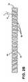
図2Aに示された実施形態において、気体流路26は、各第1および第2の表面18、22に直交する方向に延伸し、光学的に透明な物品14を貫通している。気体流路は、略円筒状であるが、楕円形、三角形、正方形、または、もっと多数の辺を有する多角形を含む様々な形状であってもよい。更に、気体流路26は、窓10に亘って、形状が異なっていてもよいと理解されるべきである。気体流路26は、略均一な大きさを有するように図示されているが、気体流路26は、第1と第2の表面18、22の間で直径が異なり、次第に細くなるように、物品14を貫通していてもよい。 In the embodiment shown in FIG. 2A, the
ここで、図2Bに示された実施形態を参照すると、気体透過性窓10の気体流路26は、第1および第2の表面18、22に直交するZ軸に対する角度αが異なる。気体流路26が、直交する軸からずれる角度は、約0°と約20°の間の範囲、または、約0.1°と約15°の間の範囲、または、約0.1°と約10°の間の範囲であってもよい。図示された実施形態において、気体流路26が傾く角度は、物品14の中心領域または点からの距離が増加するにつれて、増加する。他の実施形態においては、気体流路26が傾く角度は、物品14上の位置に関係なく変化するか、または、様式を形成してもよい。気体流路26を傾斜させることは、気体が物品14を流れ抜け易くするように、および/または、気体透過性窓10の片側に位置する点光源から物品14を通って送られた光のアーチファクトの発生を最小にするように、行われてもよい。 Referring now to the embodiment shown in FIG. 2B, the
ここで、図2Cを参照すると、いくつかの実施形態において、光学的に透明な物品14は、多数の光学的に透明なシート40を含んでいてもよい。複数の光学的に透明なシート40を、組み立てて接合し、光学的に透明な物品14を形成してもよい。各シート40が、複数の孔44を画成している。シート40が組み立てられる場合に、孔44は、実質的に位置合わせされて、気体流路26を形成してもよい。物品14が、このように多数のシート40から構成される実施形態は、より小さい構成要素の処理を可能にしながら、高アスペクト比の気体流路26を提供する点で、有利である。図2Bに示された実施形態に関して記載したのと同様に、気体流路26は、直交するZ軸に対し角度αで、複数のシート40を貫通するように穴あけして形成されてもよいと、理解されるべきである。 Referring now to FIG. 2C, in some embodiments, the optically
ここで、図3AからCを参照すると、一実施形態によれば、窓10の物品14を貫通する気体流路26を形成するのに、超短パルスレーザを使用してもよい。気体流路26の形成を可能にする光学的構成の詳細は、以下に、および、2013年1月15日出願の米国仮特許出願第61/752,489号明細書に記載され、その内容は、本明細書に完全に開示されているものとして、全体として参照により、本明細書に組み込まれる。更に、2014年10月31日出願の米国特許出願第14/530,410号明細書も、本明細書に完全に開示されているものとして、全体として参照により、本明細書に組み込まれる。短パルスレーザの概念の本質は、アキシコンレンズを、光学レンズアセンブリで用いて、高アスペクト比の気体流路26の領域を、超短(ピコ秒またはフェムト秒の持続時間の)ベッセルビームを用いて形成することである。換言すれば、アキシコンレンズは、レーザ光線を、物品14の本体内の略円筒状の形状で高アスペクト比を有する高強度領域へと、集光する。集光されたレーザ光線の高い強度により、レーザの電磁場と物品14の物質の間で非線形相互作用が起こり、レーザエネルギーが、物品14に伝達されて、気体流路26の構成部分となる欠陥の形成を引き起こす。しかしながら、物品14のうちレーザエネルギーが高くない領域(例えば、物品の第1の表面18、物品14のうち中心収束線の周囲の体積部分)では、物質はレーザ光に対し透明で、レーザ光から物質へのエネルギーの伝達作用がないということを、認識することが重要である。本開示の文脈の中では、吸収が、物質の深さ1ミリメートル当たり、約10%未満、好ましくは、約1%未満の場合に、物質は、このレーザ光の波長に対し略透明である。結果的に、レーザ光の強度が、非線形閾値未満の領域では、物品14は変化しない。 Referring now to FIGS. 3A-C, according to one embodiment, an ultrashort pulse laser may be used to form the
超短パルスレーザを使用することで、1つ以上の高エネルギーパルス、または、高エネルギーパルスの1つ以上のバーストを用いて、光学的に透明な物品14の中に、微細な(例えば、直径が、約0.1マイクロメートルと約0.5マイクロメートルの範囲、または、約0.1マイクロメートルと約2.0マイクロメートルの範囲の)気体流路26を、形成可能である。気体流路26は、レーザ光によって改質された物品14の物質の領域である。レーザ誘起された改質は、物品14の物質の構造を破壊させものである。構造的破壊は、圧縮、融解、物質の除去、再配列、および、結合の分裂を含む。気体流路26は、物品14の内部まで延伸し、レーザ光の(略円形の)断面形状と一致する断面形状を有する。気体流路26が異なる形状を有する実施形態において、気体流路26は、物品14および/またはレーザを移動させながら、多数のパルスにより形成されてもよい。作られた気体流路26の平均直径は、約0.1マイクロメートルから約50マイクロメートルの範囲、または、約1マイクロメートルから約20マイクロメートルの範囲、または、約2マイクロメートルから約10マイクロメートルの範囲、または、約0.1マイクロメートルから約5マイクロメートルの範囲であってもよい。本明細書に開示された実施形態において、気体流路26を囲む、破壊または改質された(例えば、圧縮、融解、または、他の方法で変えられた)物質の領域は、約50マイクロメートル未満の直径、特に、約10マイクロメートル未満の直径を有することが好ましい。 By using an ultrashort pulse laser, one or more high energy pulses, or one or more bursts of high energy pulses, are used to make fine (eg, diameter) in an optically
個々の気体流路26は、数百キロヘルツ(例えば、1秒当たり、数十万)の速さで形成しうる。したがって、レーザ光源と物品14の相対的な動きにつれて、気体流路26を、互いに隣接して、どのような望ましい様式でも、配置しうる。気体流路26の空間的分離度および大きさは、少なくとも部分的には、窓10の望ましい透過率に基づいて、選択されてもよい。
図3Aおよび3Bに戻り、物品14のレーザ穴あけ方法は、パルスレーザ光線50を、光線の伝播方向に沿って見たレーザ光線の焦線54へと合焦する工程を含む。レーザ光線の焦線54は、典型的には、場のプロファイルが、横方向に(つまり、伝播方向に)、ガウス関数よりゆっくりと減衰する特定の関数によって与えられる、例えば、ベッセルビーム、エアリービーム、ウェーバービーム、および、マシュービーム(つまり、非回折光線)などの様々な方法で、形成しうる。レーザ(不図示)は、光学アセンブリ62の光線入射側58で、パルスレーザ光線50を射出し、パルスレーザ光線50は、光学アセンブリ62へ入射する。光学アセンブリ62は、入射したレーザ光線を、出射側で、光線方向に沿った所定の拡大範囲(焦線の長さL)に亘る、レーザ光線の焦線54へと向ける。処理すべき物品14は、光学アセンブリ62の後段に、光線経路内に位置決めされ、レーザ光線50の焦線54と、少なくとも部分的に重なっている。 Returning to FIGS. 3A and 3B, the laser drilling method of the
図3Aに示されるように、物品14は、光線の縦軸に略垂直に、したがって、光学アセンブリ62によって形成された同じ焦線54の後で、位置合わせされ(基板は、描画平面に垂直)、光線方向に沿って見た場合、物品14は、光線方向に見た焦線54が、物品14の第1の表面18より前で始まり、物品14の第2の表面22の後で終わるように、つまり、物品14を貫通して延伸するように、焦線54に対して置かれる。レーザ光線の焦線54が物品14と重なる領域において、つまり、焦線54が占める物品14の領域において、(レーザ光線の焦線54に沿って適切なレーザ強度の場合には、)レーザ光線の焦線54は、光線の縦方向と位置合わせされた区分66を、このように形成し、それに沿って、物品14に、誘起非線形吸収が発生する。誘起非線形吸収は、物品内に、区分66に沿って、気体流路26を形成する。欠陥線の形成は、局所だけではなく、誘起吸収した区分66の全長に亘って延伸する。物品14を貫通して延伸するように図示しているが、焦線54は、物品14内に部分的にのみ延伸し、それによって、第1と第2の表面18、22の間を延伸するものではない気体流路26を形成してもよいことに、留意すべきである。誘起吸収した区分(または、気体流路26が形成された物品14の物質内の区分)の平均直径または範囲には、参照符号Dが付されている。平均範囲Dは、レーザ光線の焦線54の平均直径、つまり、平均スポット直径に、略一致する。局所的加熱および物品14の膨張により、加熱された物質の膨張による張力が生じるため、微細な亀裂が形成されるかもしれず、張力は、パルスレーザ光線50が物品14に接触する表面(例えば、第1または第2の表面18、22)において、最も高いことに、留意すべきである。 As shown in FIG. 3A, the
図3Bに示されるように、物品14の第1および第2の表面に直交する軸とパルスレーザ光線50とが斜めになることで、物品14内にレーザ光線の焦線54が形成される角度が変わる。光線の焦線54が物品14に接触する角度を変えることによって、気体流路26を、区分66に沿って物品を貫通する角度で、形成してもよい。レーザ光線の焦線54は、物品14に、約0°から約20°の範囲、または、約0.5°から約15°の範囲、または、約1°から約10°の範囲の角度で、入射してもよい。 As shown in FIG. 3B, the angle at which the
代わりの実施形態において、気体流路26は、レーザパーカッション穴あけにより、物品14内に形成されてもよい。パーカッション穴あけは、適切な波長および強度を有するレーザを用いて行われ、レーザスポットの大きさが、最終的な穴の大きさを決定する。使用してもよい波長は、約100ナノメートルと約1070ナノメートルの間の範囲、または、約150ナノメートルと約400ナノメートルの間の範囲であってもよい。例示的実施形態において、レーザは、約355ナノメートルの波長を有する紫外線レーザ光線を利用してもよい。穴あけの間、レーザは、物品14の表面(例えば、第1または第2の表面18、22)上の、約1マイクロメートルから約20マイクロメートルの範囲、または、約3マイクロメートルから約10マイクロメートルの範囲の直径を有するガウススポットに合焦される。レーザ光は、パルス状で、物品14上の同じ位置に、繰り返し当たる。レーザパルス持続時間は、約1ナノ秒と約100ナノ秒の間の範囲、または、約10ナノ秒と約25ナノ秒の間の範囲であってもよい。レーザは、毎秒約50,000パルスから、毎秒約150,000パルスまでの間、更に特に、毎秒約100,000パルスの性能を有していてもよい。物質の一部が、物品14から、各パルスにより除去され、気体流路26が形成され始める。気体流路26が、物品14内に形成されるにつれて、気体流路26は、レーザ光線を閉じ込めて、物品14を貫通する細長い孔を形成する。レーザ光は、パルス状に、気体流路26が、物品14内で望ましい深さになる(例えば、物品14を完全に貫通する)まで射出され、次に、レーザは、停止される。次に、レーザ光線と物品14は、互いに相対的に移動され、工程が繰り返されて、次の気体流路26が形成される。パーカッション穴あけは、気体流路26が、次第に細くなるのを可能にしてもよい。例えば、パーカッション穴あけを行うレーザ光が、物品14の第1の表面18に入射する一実施形態において、気体流路26は、第1の表面18での開口部が、約15から約25マイクロメートルの直径、および、物品14の第2の表面22上の開口部が、約5マイクロメートルから約10マイクロメートルの直径を、有していてもよい。 In an alternative embodiment, the
採用するレーザ穴あけ方法に関わらず、気体流路26の形成後に、気体流路26の直径を増加させるか、または、気体流路26に存在する任意の微細亀裂を修復するのが、望ましいかもしれない。一実施形態において、化学エッチング処理を採用して、気体流路26を広げ、更に、レーザ穴あけ中に形成された任意の微細亀裂または機械的に弱い領域を修復するのが、望ましいかもしれない。エッチング液70(図3C)は、フッ化水素酸、硝酸、塩酸、水酸化カリウム、水酸化ナトリウム、および/または、それらの組合せを含んでいてもよい。例示的な一実施形態において、エッチング液は、約5%のフッ化水素酸、および、約10%の硝酸を含み、残りは、水であってもよい。典型的には、処理は、物品14を、エッチング液70の溶液に浸漬することによって行われる。酸の濃度、溶液の温度、および露光時間を制御することによって、物品14から除去される物質の総量を調節しうる。更に、エッチングは、物品14を揺り動かしながら、または、超音波が存在する状態で行って、損傷領域内の流体交換を増加させて、総エッチング時間を短くしてもよい。 Regardless of the laser drilling method employed, it may be desirable to increase the diameter of the
図3Cに示されたように、積層して配列された多数の光学的に透明なシート40を用いる物品14の実施形態は、急速処理で形成された気体流路26を有していてもよい。第1の工程において、複数のシート40が、互いに積層して配列されて、レーザの下に位置する積層体74を形成し、次に、概略を上述したレーザ穴あけ方法の1つによりレーザで穴あけされて、シート40を貫通する複数の孔が形成される。積層中に、シート40に、追加の孔または基準となる印を付け、後で、積層体74の再組立てが可能なようにしてもよい。例えば、1つ以上の開口部は、シート40の縁部に位置し、積層体74の組立て中および再組立て中に使用されてもよい保持ピンを受け付けるように、構成されてもよい。そのような保持ピンは、積層体74内のシート40を、速く、容易に位置合わせするのを可能にするだろう。各シート40は、約0.1ミリメートルと約2.0ミリメートルの厚さを有していてもよい。レーザ光線の焦線54を用いたレーザ穴あけの実施形態において、焦線54は、積層シート40全体を、または、シート40の一部のみを、貫通して延伸してもよい。例えば、焦線54は、積層体74内に位置し、パルス状で、次に、積層体74を貫通して下方に移動してもよい。図3Cは、超短パルス光線を用いるものとして図示しているが、レーザパーカッション穴あけを用いて、同様の結果を得てもよいと、理解されるべきである。 As shown in FIG. 3C, an embodiment of
第1の工程が完了すると、シート40を互いに分離する第2の工程が行われ、シート40は、上述したように、エッチング液70でエッチングされる。シート40を別々にエッチングすることで、気体流路26の修復および拡大が均等に行われるように、エッチング液70が、孔44に完全に入るのを確実にする。最後に、エッチング後に、シート40が清浄され、組み立てられて、物品14を形成する。物品14が多数のシート40で構成される実施形態において、物品14は、保持ピン、または、他の適切な接合および位置合わせ技術により、まとめて保持されてもよい。シート40を位置合わせすることで、孔44が、実質的に位置合わせされ、それによって、気体流路26が形成される。この技術を利用することで、エッチング液70が通り抜ける距離が短くなるので、物品14内で、高アスペクト比の適切なエッチングが確実に行われうる。更に、複数のシート40に、同時にレーザ穴あけを行うことは、処理量の増加という点で、製造上の利点を提供するかもしれない。 When the first step is completed, a second step of separating the
物品14に対する気体流路26のレーザ穴あけは、物品に、イオン交換処理が行われる前または後に、行われてもよいと理解されるべきである。例示的なイオン交換処理は、物品14に、アルカリ、アルカリ土類、および/または、遷移金属を添加する工程を含む。 It should be understood that laser drilling of the
ここで、図4Aを参照すると、気体透過性窓10は、液体界面付加製造装置100での使用に適していてもよい。そのような実施形態において、気体透過性窓10は、ガラス、積層ガラス、および/または、ガラス複合材を、含んでいてもよい。図示された実施形態において、装置100は、液体ポリマー槽108を保持する筐体104を含む。装置100は、槽108の中へ、および、槽108の外へと移動されてもよい機械的ステッパー112を有する。機械的ステッパー112は、ポリマー部120が、その上で成長してもよい造形面116を含む。気体透過性窓10は、筐体104の底部に沿って位置し、光源128からの紫外線光124が、ミラー132で反射されて、槽108に入射するのを可能にする。いくつかの実施形態において、気体透過性窓10は、機械的留め具により、適切な位置に保持されてもよい。特定の実施形態において、気体透過性窓10は、2辺の長さが、それぞれ、約10.16センチメートル(4インチ)と17.78センチメートル(7インチ)から、約22.86センチメートル(9インチ)と40.64センチメートル(16インチ)のおよその寸法を有していてもよい。 Here, referring to FIG. 4A, the gas
光源128は、コントローラおよびメモリーに連結されて、作製すべきポリマー部分120の区分の画像を紫外線光124で投影するように構成された、投影機であってもよい。ポリマー部分120の一部が、造形面116に形成されると、機械的ステッパー112が、上方に進み、ポリマー部分120を、気体透過性窓10から離れるように移動させ、槽108内の流体が、ポリマー部分120と気体透過性窓10の間を流れるのを可能にする。次に、光源128は、ポリマー部分120の異なる画像を投影し、それによりポリマー部分120の次の部分が形成されるように、槽108に、ポリマー部分120上で、重合化わせる。ポリマー部分120が、気体透過性窓10上に、直接形成されるのを防ぐために、気体流路26は、重合化を阻止する気体(例えば、酸素)が通過して、槽108内に入ることを可能にし、それによって、槽108の重合化が起きない「デッドゾーン」を形成する。重合化を阻止する気体は、気体源136により供給される。気体源136は、約0.1気圧(約101hPa)から約10気圧(約10132hPa)の圧力で気体を提供してもよい。ポリマー部分120の望ましい成長速度を決定することによって、デッドゾーンの厚さ、したがって、導入される重合化を阻止する気体の必要量を、決定してもよい。気体透過性窓10を貫通して配置された気体流路26の直径および個数を変えることで、必要な透過率を満たして、部分120の適切な成長を可能にしてもよい。 The
図4Bに図示されると共に上述したように、気体流路26は、気体透過性窓10の物品14を貫通する角度で配置されていてもよい。そのような角度にすることで、窓10を通る紫外線光124が、ガラス物品14によって減衰されないので、透過率を高くすることが可能である。更に、気体流路26を、反射した紫外線光束124の軸に沿って位置合わせすることによって、紫外線光124が、物品14に接触せずに、斜めの気体流路126を通り抜けるので、窓10による紫外線光124の散乱が減少する。紫外線光124は、ポリマー部分120を形成し、成長させるメカニズムであるので、その光に歪みがあると、結果的にポリマー部分120に光学的アーチファクトを発生させるかもしれないので、このことには、利点がある。 As shown in FIG. 4B and as described above, the
他の実施形態において、気体透過性窓10は、気体透過性窓10に亘って、圧力差を最小にするのが望ましいであろう航空の利用例で、使われてもよい。例えば、気体透過性窓10は、航空機用の二重ガラス窓の1枚のガラス板を形成してもよい。そのような実施形態において、圧力差により、窓が、砕けたり、他の状態で割れたりすることがないように、ガラス板同士の間に閉じ込められた気体が、航空機客室区域の空気空間と等しい圧力になるのが可能であることが、望ましいだろう。 In other embodiments, the gas
当業者には、請求項の精神または範囲から逸脱することなく、様々な変更および変形が可能なことが明らかであろう。 It will be apparent to those skilled in the art that various modifications and variations can be made without departing from the spirit or scope of the claims.
以下、本発明の好ましい実施形態を項分け記載する。 Hereinafter, preferable embodiments of the present invention will be described in terms of items.
実施形態1
気体透過性ガラス窓において、
厚さが約0.1ミリメートルより厚く、第1の表面および第2の表面を画成する光学的に透明なガラス物品と、
前記物品を前記第1の表面から前記第2の表面へと貫通して配置された、複数の気体流路と、
を含み、
前記気体流路は、前記物品の表面領域の約1.0%未満を占めると共に、該物品が約10バーラー(約75×10−18m4/(N・s))と約2000バーラー(約15002×10−18m4/(N・s))の間の気体透過率を有するように、構成されたものである、
気体透過性ガラス窓。Embodiment 1
In the gas permeable glass window,
An optically clear glass article having a thickness greater than about 0.1 millimeter and defining the first surface and the second surface;
A plurality of gas flow paths disposed through the article from the first surface to the second surface;
Including
The gas flow path occupies less than about 1.0% of the surface area of the article and the article is about 10 barrers (about 75 × 10−18 m4 / (N · s)) and about 2000 barrers (about It is configured to have a gas permeability between 15002 × 10−18 m4 / (N · s).
Gas permeable glass window.
実施形態2
前記気体透過率が、約100バーラー(約750×10−18m4/(N・s))と約500バーラー(約3751m4/(N・s))の間である、実施形態1に記載の気体透過性窓。
Embodiment 1. The embodiment 1 wherein the gas permeability is between about 100 barrers (about 750 × 10−18 m4 / (N · s)) and about 500 barrs (about 3751 m4 / (N · s)). Gas permeable window.
実施形態3
前記気体流路が、前記物品の前記表面領域の約0.05%未満を占めるものである、実施形態2に記載の気体透過性窓。Embodiment 3
The gas permeable window according to
実施形態4
前記ガラス物品は、積層された複数のガラスシートを含み、各前記ガラスシートは、貫通して延伸する複数の孔を有し、
更に、前記ガラスシートは、前記孔が実質的に位置合わせされて、気体流路を形成するように積層されたものである、実施形態1に記載の気体透過性窓。
The glass article includes a plurality of laminated glass sheets, each glass sheet having a plurality of holes extending therethrough,
Furthermore, the glass sheet is a gas permeable window according to the first embodiment, in which the holes are substantially aligned and laminated so as to form a gas flow path.
実施形態5
前記気体流路は、前記物品の全体に、ランダムに分布し、約5マイクロメートルと約400マイクロメートルの間、互いに離間したものである、実施形態1に記載の気体透過性窓。Embodiment 5
The gas permeable window according to embodiment 1, wherein the gas flow paths are randomly distributed throughout the article and are spaced apart from each other between about 5 micrometers and about 400 micrometers.
実施形態6
前記気体流路が、約10:1と約12,000:1の間のアスペクト比を有するものである、実施形態5に記載の気体透過性窓。Embodiment 6
6. The gas permeable window according to embodiment 5, wherein the gas flow path has an aspect ratio between about 10: 1 and about 12,000: 1.
実施形態7
前記気体流路が、約0.25マイクロメートルと約50.0マイクロメートルの間の直径を有し、前記物品の前記気体透過率が、約500バーラー(約3751×10−18m4/(N・s))未満である、実施形態1に記載の気体透過性窓。Embodiment 7
The gas flow path has a diameter between about 0.25 micrometers and about 50.0 micrometers, and the gas permeability of the article is about 500 barrers (about 3751 × 10−18 m4 / ( N.s)) The gas permeable window according to embodiment 1, wherein
実施形態8
前記気体流路が、前記第1および第2の表面に直交する軸に対して約0°と約15°の間の角度で、前記物品を貫通して配置されているものである、実施形態7に記載の気体透過性窓。Embodiment 8
An embodiment wherein the gas flow path is disposed through the article at an angle between about 0 ° and about 15 ° relative to an axis orthogonal to the first and second surfaces. The gas permeable window according to 7.
実施形態9
前記流路の前記角度が、中心点からの距離が増加するにつれて、増加するものである、実施形態8に記載の気体透過性窓。Embodiment 9
The gas permeable window according to embodiment 8, wherein the angle of the flow path increases as the distance from the center point increases.
実施形態10
気体透過性ガラス窓の形成方法において、
第1の表面および第2の表面を有する光学的に透明なガラス物品を、提供する工程と、
パルスレーザ光線を、前記光線の伝播方向に沿って見たレーザ光線の焦線に、合焦する工程と、
前記レーザ光線の焦線を、光学的に透明な前記ガラス物品内に、該ガラス物品の前記第1の表面への入射角で繰り返し向けることにより、複数の気体流路を、該物品内に形成する工程であって、該レーザ光線の焦線は、誘起吸収を該物品内に発生させて、各前記誘起吸収が、該物品内に、該第1の表面から前記第2の表面まで、該レーザ光線の焦線に沿った気体流路を形成するものである工程と、
を有し、
前記気体流路の個数および直径は、前記物品の望ましい気体透過率に基づいて、決定されるものである、方法。
In the method of forming a gas permeable glass window,
Providing an optically clear glass article having a first surface and a second surface;
Focusing the pulsed laser beam on the focal line of the laser beam viewed along the propagation direction of the beam;
A plurality of gas flow paths are formed in the article by repeatedly directing the focal line of the laser beam into the optically transparent glass article at an angle of incidence on the first surface of the glass article. The focal line of the laser beam causes induced absorption to occur in the article, and each of the induced absorptions in the article from the first surface to the second surface, Forming a gas flow path along the focal line of the laser beam;
Have
The method wherein the number and diameter of the gas flow paths are determined based on the desired gas permeability of the article.
実施形態11
パルス持続時間が、約15ピコ秒未満である、実施形態10に記載の方法。Embodiment 11
Embodiment 11. The method of
実施形態12
エッチング剤を与えて、前記気体流路を拡大させる工程を、
更に含むものである、実施形態11に記載の方法。Embodiment 12
Providing an etchant to expand the gas flow path;
Embodiment 12. The method of embodiment 11 further comprising:
実施形態13
前記気体流路が、約0°と約15°の間の角度で、前記物品を貫通して配置されると共に、該流路の前記角度が、中心点からの距離が増加するにつれて、増加するように、前記物品の前記表面への前記入射角を変化させるものである、実施形態10に記載の方法。Embodiment 13
The gas flow path is disposed through the article at an angle between about 0 ° and about 15 °, and the angle of the flow path increases as the distance from the center point increases. Thus, the method of
実施形態14
前記気体流路が、約10:1と約12,000:1の間のアスペクト比を有するものである、実施形態10に記載の方法。
The method of
実施形態15
前記物品の前記気体透過率が、約100バーラー(約750×10−18m4/(N・s))と約500バーラー(約3751×10−18m4/(N・s))の間である、実施形態14に記載の方法。Embodiment 15
The gas permeability of the article is between about 100 barrers (about 750 × 10−18 m4 / (N · s)) and about 500 barrers (about 3751 × 10−18 m4 / (N · s)). The method of
実施形態16
気体透過性窓において、
第1の表面および第2の表面を画成する光学的に透明な物品と、
前記第1の表面から前記第2の表面へと延伸する複数の気体流路と、
を含み、
前記気体流路は、前記第1および第2の表面に直交する軸に対して約0°と約15°の間の角度で、配置されていると共に、該流路の前記角度が、中心点からの距離が増加するにつれて、増加しているものである、
気体透過性窓。Embodiment 16
In the gas permeable window,
An optically transparent article defining a first surface and a second surface;
A plurality of gas flow paths extending from the first surface to the second surface;
Including
The gas flow path is disposed at an angle between about 0 ° and about 15 ° with respect to an axis orthogonal to the first and second surfaces, and the angle of the flow path is a center point As the distance from increases,
Gas permeable window.
実施形態17
前記気体流路が、約10:1と約12,000:1の間のアスペクト比を有すると共に、前記物品の表面領域の約0.01%未満を占めるものである、実施形態16に記載の気体透過性窓。Embodiment 17
17. The embodiment of embodiment 16, wherein the gas flow path has an aspect ratio between about 10: 1 and about 12,000: 1 and occupies less than about 0.01% of the surface area of the article. Gas permeable window.
実施形態18
光学的に透明な前記物品は、積層された複数の透明なシートを含み、各前記シートは、貫通して延伸する複数の孔を有し、
更に、前記透明なシートは、前記孔が実質的に位置合わせされて、気体流路を形成するように積層されたものである、実施形態17に記載の気体透過性窓。
The optically transparent article includes a plurality of laminated transparent sheets, each sheet having a plurality of holes extending therethrough,
Furthermore, the said transparent sheet | seat is a gas-permeable window of Embodiment 17 in which the said hole is substantially aligned and laminated | stacked so that a gas flow path may be formed.
実施形態19
前記物品の気体透過率が、約100バーラー(約750×10−18m4/(N・s))より高いものである、実施形態18に記載の気体透過性窓。Embodiment 19
Embodiment 19. The gas permeable window of
実施形態20
光学的に透明な前記物品は、少なくとも1つのイオン交換領域を有するガラスを含むものである、実施形態19に記載の気体透過性窓。Embodiment 20.
Embodiment 20. The gas permeable window according to embodiment 19, wherein the optically transparent article comprises glass having at least one ion exchange region.
10 気体透過性窓
14 物品
18 第1の表面
22 第2の表面
26 気体流路
40 シート
44 孔
100 装置
104 筐体
108 槽
112 機械的ステッパー
116 造形面
120 ポリマー部分DESCRIPTION OF
Claims (11)
Translated fromJapanese厚さが約0.1ミリメートルより厚く、第1の表面および第2の表面を画成する光学的に透明なガラス物品と、
前記物品を前記第1の表面から前記第2の表面へと貫通して配置された、複数の気体流路と、
を含み、
前記気体流路は、前記物品の表面領域の約1.0%未満を占めると共に、該物品が約10バーラー(約75×10−18m4/(N・s))と約2000バーラー(約15002×10−18m4/(N・s))の間の気体透過率を有するように、構成されたものである、
気体透過性窓。In the gas permeable glass window,
An optically clear glass article having a thickness greater than about 0.1 millimeter and defining the first surface and the second surface;
A plurality of gas flow paths disposed through the article from the first surface to the second surface;
Including
The gas flow path occupies less than about 1.0% of the surface area of the article and the article is about 10 barrers (about 75 × 10−18 m4 / (N · s)) and about 2000 barrers (about It is configured to have a gas permeability between 15002 × 10−18 m4 / (N · s).
Gas permeable window.
第1の表面および第2の表面を画成する光学的に透明な物品と、
前記第1の表面から前記第2の表面へと延伸する複数の気体流路と、
を含み、
前記気体流路は、前記第1および第2の表面に直交する軸に対して約0°と約15°の間の角度で、配置されていると共に、該流路の前記角度が、中心点からの距離が増加するにつれて、増加しているものである、
気体透過性窓。In the gas permeable window,
An optically transparent article defining a first surface and a second surface;
A plurality of gas flow paths extending from the first surface to the second surface;
Including
The gas flow path is disposed at an angle between about 0 ° and about 15 ° with respect to an axis orthogonal to the first and second surfaces, and the angle of the flow path is a center point As the distance from increases,
Gas permeable window.
更に、前記ガラスシートは、前記孔が実質的に位置合わせされて、気体流路を形成するように積層されたものである、請求項1または2に記載の気体透過性窓。The glass article includes a plurality of laminated glass sheets, each glass sheet having a plurality of holes extending therethrough,
Furthermore, the said glass sheet is a gas-permeable window of Claim 1 or 2 by which the said hole is substantially aligned and laminated | stacked so that a gas flow path might be formed.
第1の表面および第2の表面を有する光学的に透明なガラス物品を、提供する工程と、
パルスレーザ光線を、前記光線の伝播方向に沿って見たレーザ光線の焦線に、合焦する工程と、
前記レーザ光線の焦線を、光学的に透明な前記ガラス物品内に、該ガラス物品の前記第1の表面への入射角で繰り返し向けることにより、前記複数の気体流路を、該物品内に形成する工程であって、該レーザ光線の焦線は、誘起吸収を該物品内に発生させて、各前記誘起吸収が、該物品内に、該第1の表面から前記第2の表面まで、該レーザ光線の焦線に沿った気体流路を形成するものである工程と、
を有し、
前記気体流路の個数および直径は、前記物品の望ましい気体透過率に基づいて、決定されるものである、方法。In the method of forming a gas permeable glass window,
Providing an optically clear glass article having a first surface and a second surface;
Focusing the pulsed laser beam on the focal line of the laser beam viewed along the propagation direction of the beam;
By repeatedly directing the focal line of the laser beam into the optically transparent glass article at an angle of incidence on the first surface of the glass article, the plurality of gas flow paths are formed in the article. The focal line of the laser beam generates induced absorption in the article, and each of the induced absorptions in the article from the first surface to the second surface, Forming a gas flow path along the focal line of the laser beam;
Have
The method wherein the number and diameter of the gas flow paths are determined based on the desired gas permeability of the article.
Applications Claiming Priority (3)
| Application Number | Priority Date | Filing Date | Title |
|---|---|---|---|
| US201562139238P | 2015-03-27 | 2015-03-27 | |
| US62/139,238 | 2015-03-27 | ||
| PCT/US2016/023381WO2016160391A1 (en) | 2015-03-27 | 2016-03-21 | Gas permeable window and method of fabricating the same |
Publications (1)
| Publication Number | Publication Date |
|---|---|
| JP2018516215Atrue JP2018516215A (en) | 2018-06-21 |
Family
ID=55699815
Family Applications (1)
| Application Number | Title | Priority Date | Filing Date |
|---|---|---|---|
| JP2017550572ACeasedJP2018516215A (en) | 2015-03-27 | 2016-03-21 | Gas permeable window and manufacturing method thereof |
Country Status (7)
| Country | Link |
|---|---|
| US (1) | US10525657B2 (en) |
| EP (1) | EP3274313A1 (en) |
| JP (1) | JP2018516215A (en) |
| KR (1) | KR20170131638A (en) |
| CN (1) | CN107666983B (en) |
| TW (1) | TW201638042A (en) |
| WO (1) | WO2016160391A1 (en) |
Cited By (1)
| Publication number | Priority date | Publication date | Assignee | Title |
|---|---|---|---|---|
| JP2022519724A (en)* | 2019-02-08 | 2022-03-24 | コーニング インコーポレイテッド | A method for laser machining transparent workpieces using a pulsed laser beam focal lens and steam etching |
Families Citing this family (41)
| Publication number | Priority date | Publication date | Assignee | Title |
|---|---|---|---|---|
| EP2754524B1 (en) | 2013-01-15 | 2015-11-25 | Corning Laser Technologies GmbH | Method of and apparatus for laser based processing of flat substrates being wafer or glass element using a laser beam line |
| EP2781296B1 (en) | 2013-03-21 | 2020-10-21 | Corning Laser Technologies GmbH | Device and method for cutting out contours from flat substrates using a laser |
| US10293436B2 (en) | 2013-12-17 | 2019-05-21 | Corning Incorporated | Method for rapid laser drilling of holes in glass and products made therefrom |
| US11556039B2 (en) | 2013-12-17 | 2023-01-17 | Corning Incorporated | Electrochromic coated glass articles and methods for laser processing the same |
| US10442719B2 (en) | 2013-12-17 | 2019-10-15 | Corning Incorporated | Edge chamfering methods |
| CN106687419A (en) | 2014-07-08 | 2017-05-17 | 康宁股份有限公司 | Methods and apparatuses for laser processing materials |
| EP3169479B1 (en) | 2014-07-14 | 2019-10-02 | Corning Incorporated | Method of and system for arresting incident crack propagation in a transparent material |
| CN208586209U (en) | 2014-07-14 | 2019-03-08 | 康宁股份有限公司 | A system for forming contoured multiple defects in a workpiece |
| KR20170028943A (en)* | 2014-07-14 | 2017-03-14 | 코닝 인코포레이티드 | System for and method of processing transparent materials using laser beam focal lines adjustable in length and diameter |
| JP6788571B2 (en) | 2014-07-14 | 2020-11-25 | コーニング インコーポレイテッド | Interface blocks, systems and methods for cutting transparent substrates within a wavelength range using such interface blocks. |
| CN107406293A (en) | 2015-01-12 | 2017-11-28 | 康宁股份有限公司 | The substrate through heat tempering is cut by laser using Multiphoton Absorbtion method |
| WO2016138054A1 (en) | 2015-02-27 | 2016-09-01 | Corning Incorporated | Optical assembly having microlouvers |
| HUE055461T2 (en) | 2015-03-24 | 2021-11-29 | Corning Inc | Laser cutting and processing of display glass compositions |
| JP2018516215A (en) | 2015-03-27 | 2018-06-21 | コーニング インコーポレイテッド | Gas permeable window and manufacturing method thereof |
| WO2016172788A1 (en)* | 2015-04-30 | 2016-11-03 | Fortier, Raymond | Improved stereolithography system |
| KR20180081489A (en)* | 2015-09-25 | 2018-07-16 | 카본, 인크. | Build plate assembly for continuous liquid phase printing with illumination panels and related methods, systems and apparatus |
| US10442720B2 (en)* | 2015-10-01 | 2019-10-15 | AGC Inc. | Method of forming hole in glass substrate by using pulsed laser, and method of producing glass substrate provided with hole |
| US11993015B2 (en) | 2015-12-03 | 2024-05-28 | Carbon, Inc. | Build plate assemblies for continuous liquid interphase printing having lighting panels and related methods, systems and devices |
| EP3507057A1 (en) | 2016-08-30 | 2019-07-10 | Corning Incorporated | Laser processing of transparent materials |
| US10730783B2 (en) | 2016-09-30 | 2020-08-04 | Corning Incorporated | Apparatuses and methods for laser processing transparent workpieces using non-axisymmetric beam spots |
| EP3529214B1 (en) | 2016-10-24 | 2020-12-23 | Corning Incorporated | Substrate processing station for laser-based machining of sheet-like glass substrates |
| US10752534B2 (en) | 2016-11-01 | 2020-08-25 | Corning Incorporated | Apparatuses and methods for laser processing laminate workpiece stacks |
| US10857726B2 (en)* | 2017-01-24 | 2020-12-08 | Continuous Composites Inc. | Additive manufacturing system implementing anchor curing |
| CN110573470A (en)* | 2017-04-26 | 2019-12-13 | 康宁股份有限公司 | Micro-perforated glass laminate and method for producing same |
| US10626040B2 (en) | 2017-06-15 | 2020-04-21 | Corning Incorporated | Articles capable of individual singulation |
| DE102018100443A1 (en)* | 2018-01-10 | 2019-07-11 | Schott Ag | Process and device for the production of glass precursors and glass products |
| EP3755935A4 (en)* | 2018-02-19 | 2021-10-20 | Kattmann Elias, LLC | DYNAMIC MULTI-PANEL INSULATION ARRANGEMENT AND SYSTEM |
| US12138887B2 (en) | 2018-02-19 | 2024-11-12 | Kattmann Elias, LLC | Dynamic multi-pane insulating assembly and system |
| US11161325B2 (en) | 2019-02-19 | 2021-11-02 | Kattmann Elias, LLC | Dynamic multi-pane insulating assembly and system |
| US11938678B2 (en)* | 2018-05-05 | 2024-03-26 | Luxcreo (Beijing) Inc. | Adhesion blocking element, three-dimensional printing device, and three-dimensional printing method |
| US11059131B2 (en) | 2018-06-22 | 2021-07-13 | Corning Incorporated | Methods for laser processing a substrate stack having one or more transparent workpieces and a black matrix layer |
| CN108930491A (en)* | 2018-07-23 | 2018-12-04 | 赣州市翔义科技有限公司 | A kind of energy-saving and environment-friendly compound glass and installation method |
| US10470300B1 (en)* | 2018-07-24 | 2019-11-05 | AGC Inc. | Glass panel for wiring board and method of manufacturing wiring board |
| EP3873722A4 (en) | 2018-11-01 | 2022-08-17 | Stratasys, Inc. | Method for build separation from a curing interface in an additive manufacturing process |
| US11104075B2 (en) | 2018-11-01 | 2021-08-31 | Stratasys, Inc. | System for window separation in an additive manufacturing process |
| US11679555B2 (en) | 2019-02-21 | 2023-06-20 | Sprintray, Inc. | Reservoir with substrate assembly for reducing separation forces in three-dimensional printing |
| US10766194B1 (en) | 2019-02-21 | 2020-09-08 | Sprintray Inc. | Apparatus, system, and method for use in three-dimensional printing |
| ES3026144T3 (en)* | 2019-03-29 | 2025-06-10 | Kattmann Elias Llc | Dynamic multi-pane insulating assembly and system |
| US11642848B2 (en)* | 2019-09-23 | 2023-05-09 | Carbon, Inc. | Temperature responsive resin cassettes for additive manufacturing |
| US11565615B2 (en)* | 2020-04-28 | 2023-01-31 | Global Ip Holdings, Llc | Anti-microbial, partition divider assembly for a cart such as a golf cart |
| US12030135B2 (en)* | 2020-10-14 | 2024-07-09 | Applied Materials, Inc. | Methods to fabricate chamber component holes using laser drilling |
Citations (4)
| Publication number | Priority date | Publication date | Assignee | Title |
|---|---|---|---|---|
| JP2003238178A (en)* | 2002-02-21 | 2003-08-27 | Toshiba Ceramics Co Ltd | Gas introducing shower plate and method of manufacturing the same |
| JP2004351494A (en)* | 2003-05-30 | 2004-12-16 | Seiko Epson Corp | Drilling method of material transparent to laser |
| JP2013187247A (en)* | 2012-03-06 | 2013-09-19 | Nippon Hoso Kyokai <Nhk> | Interposer and method for manufacturing the same |
| US20140361463A1 (en)* | 2013-02-12 | 2014-12-11 | Eipi Systems, Inc. | Method and apparatus for three-dimensional fabrication |
Family Cites Families (388)
| Publication number | Priority date | Publication date | Assignee | Title |
|---|---|---|---|---|
| US1790397A (en) | 1931-01-27 | Glass workins machine | ||
| US2682134A (en) | 1951-08-17 | 1954-06-29 | Corning Glass Works | Glass sheet containing translucent linear strips |
| US2749794A (en) | 1953-04-24 | 1956-06-12 | Corning Glass Works | Illuminating glassware and method of making it |
| GB1242172A (en) | 1968-02-23 | 1971-08-11 | Ford Motor Co | A process for chemically cutting glass |
| US3647410A (en) | 1969-09-09 | 1972-03-07 | Owens Illinois Inc | Glass ribbon machine blow head mechanism |
| US3775084A (en) | 1970-01-02 | 1973-11-27 | Owens Illinois Inc | Pressurizer apparatus for glass ribbon machine |
| US3729302A (en) | 1970-01-02 | 1973-04-24 | Owens Illinois Inc | Removal of glass article from ribbon forming machine by vibrating force |
| US3695497A (en) | 1970-08-26 | 1972-10-03 | Ppg Industries Inc | Method of severing glass |
| US3695498A (en) | 1970-08-26 | 1972-10-03 | Ppg Industries Inc | Non-contact thermal cutting |
| DE2231330A1 (en) | 1972-06-27 | 1974-01-10 | Agfa Gevaert Ag | METHOD AND DEVICE FOR GENERATING A SHARP FOCUS |
| DE2757890C2 (en) | 1977-12-24 | 1981-10-15 | Fa. Karl Lutz, 6980 Wertheim | Method and device for producing containers from tubular glass, in particular ampoules |
| US4441008A (en)* | 1981-09-14 | 1984-04-03 | Ford Motor Company | Method of drilling ultrafine channels through glass |
| US4546231A (en) | 1983-11-14 | 1985-10-08 | Group Ii Manufacturing Ltd. | Creation of a parting zone in a crystal structure |
| US4646308A (en) | 1985-09-30 | 1987-02-24 | Spectra-Physics, Inc. | Synchronously pumped dye laser using ultrashort pump pulses |
| JPS6318756A (en) | 1986-07-09 | 1988-01-26 | Fujiwara Jiyouki Sangyo Kk | Method and device for supervising controlled temperature in organism rearing and microorganism cultivation |
| US4749400A (en) | 1986-12-12 | 1988-06-07 | Ppg Industries, Inc. | Discrete glass sheet cutting |
| DE3789858T2 (en) | 1986-12-18 | 1994-09-01 | Nippon Sheet Glass Co Ltd | Light control plates. |
| US4918751A (en) | 1987-10-05 | 1990-04-17 | The University Of Rochester | Method for optical pulse transmission through optical fibers which increases the pulse power handling capacity of the fibers |
| IL84255A (en) | 1987-10-23 | 1993-02-21 | Galram Technology Ind Ltd | Process for removal of post- baked photoresist layer |
| JPH01179770A (en) | 1988-01-12 | 1989-07-17 | Hiroshima Denki Gakuen | How to join metal and ceramics |
| US4764930A (en) | 1988-01-27 | 1988-08-16 | Intelligent Surgical Lasers | Multiwavelength laser source |
| US4907586A (en) | 1988-03-31 | 1990-03-13 | Intelligent Surgical Lasers | Method for reshaping the eye |
| US4929065A (en) | 1988-11-03 | 1990-05-29 | Isotec Partners, Ltd. | Glass plate fusion for macro-gradient refractive index materials |
| US4891054A (en) | 1988-12-30 | 1990-01-02 | Ppg Industries, Inc. | Method for cutting hot glass |
| US5112722A (en) | 1989-04-12 | 1992-05-12 | Nippon Sheet Glass Co., Ltd. | Method of producing light control plate which induces scattering of light at different angles |
| US5104210A (en) | 1989-04-24 | 1992-04-14 | Monsanto Company | Light control films and method of making |
| US5035918A (en) | 1989-04-26 | 1991-07-30 | Amp Incorporated | Non-flammable and strippable plating resist and method of using same |
| US5040182A (en) | 1990-04-24 | 1991-08-13 | Coherent, Inc. | Mode-locked laser |
| CA2123008C (en) | 1991-11-06 | 2003-01-21 | Shui T. Lai | Corneal surgery device and method |
| US5265107A (en) | 1992-02-05 | 1993-11-23 | Bell Communications Research, Inc. | Broadband absorber having multiple quantum wells of different thicknesses |
| JPH05323110A (en) | 1992-05-22 | 1993-12-07 | Hitachi Koki Co Ltd | Multi-beam generator |
| US6016223A (en) | 1992-08-31 | 2000-01-18 | Canon Kabushiki Kaisha | Double bessel beam producing method and apparatus |
| CA2112843A1 (en) | 1993-02-04 | 1994-08-05 | Richard C. Ujazdowski | Variable repetition rate picosecond laser |
| JP3293136B2 (en) | 1993-06-04 | 2002-06-17 | セイコーエプソン株式会社 | Laser processing apparatus and laser processing method |
| US6489589B1 (en) | 1994-02-07 | 2002-12-03 | Board Of Regents, University Of Nebraska-Lincoln | Femtosecond laser utilization methods and apparatus and method for producing nanoparticles |
| JP3531199B2 (en) | 1994-02-22 | 2004-05-24 | 三菱電機株式会社 | Optical transmission equipment |
| US5436925A (en) | 1994-03-01 | 1995-07-25 | Hewlett-Packard Company | Colliding pulse mode-locked fiber ring laser using a semiconductor saturable absorber |
| US5400350A (en) | 1994-03-31 | 1995-03-21 | Imra America, Inc. | Method and apparatus for generating high energy ultrashort pulses |
| US5778016A (en) | 1994-04-01 | 1998-07-07 | Imra America, Inc. | Scanning temporal ultrafast delay methods and apparatuses therefor |
| US5656186A (en) | 1994-04-08 | 1997-08-12 | The Regents Of The University Of Michigan | Method for controlling configuration of laser induced breakdown and ablation |
| DE19513354A1 (en) | 1994-04-14 | 1995-12-14 | Zeiss Carl | Surface processing equipment |
| JP2526806B2 (en) | 1994-04-26 | 1996-08-21 | 日本電気株式会社 | Semiconductor laser and its operating method |
| WO1995031023A1 (en) | 1994-05-09 | 1995-11-16 | Massachusetts Institute Of Technology | Dispersion-compensated laser using prismatic end elements |
| US5434875A (en) | 1994-08-24 | 1995-07-18 | Tamar Technology Co. | Low cost, high average power, high brightness solid state laser |
| US6016324A (en) | 1994-08-24 | 2000-01-18 | Jmar Research, Inc. | Short pulse laser system |
| US5776220A (en) | 1994-09-19 | 1998-07-07 | Corning Incorporated | Method and apparatus for breaking brittle materials |
| US5696782A (en) | 1995-05-19 | 1997-12-09 | Imra America, Inc. | High power fiber chirped pulse amplification systems based on cladding pumped rare-earth doped fibers |
| JPH09106243A (en) | 1995-10-12 | 1997-04-22 | Dainippon Printing Co Ltd | Hologram duplication method |
| US5736709A (en) | 1996-08-12 | 1998-04-07 | Armco Inc. | Descaling metal with a laser having a very short pulse width and high average power |
| US7353829B1 (en) | 1996-10-30 | 2008-04-08 | Provectus Devicetech, Inc. | Methods and apparatus for multi-photon photo-activation of therapeutic agents |
| US6301932B1 (en) | 1996-11-13 | 2001-10-16 | Corning Incorporated | Method for forming an internally channeled glass article |
| US6033583A (en) | 1997-05-05 | 2000-03-07 | The Regents Of The University Of California | Vapor etching of nuclear tracks in dielectric materials |
| US6156030A (en) | 1997-06-04 | 2000-12-05 | Y-Beam Technologies, Inc. | Method and apparatus for high precision variable rate material removal and modification |
| BE1011208A4 (en) | 1997-06-11 | 1999-06-01 | Cuvelier Georges | Capping METHOD FOR GLASS PIECES. |
| DE19728766C1 (en) | 1997-07-07 | 1998-12-17 | Schott Rohrglas Gmbh | Use of a method for producing a predetermined breaking point in a vitreous body |
| US6078599A (en) | 1997-07-22 | 2000-06-20 | Cymer, Inc. | Wavelength shift correction technique for a laser |
| JP3264224B2 (en) | 1997-08-04 | 2002-03-11 | キヤノン株式会社 | Illumination apparatus and projection exposure apparatus using the same |
| DE19750320C1 (en) | 1997-11-13 | 1999-04-01 | Max Planck Gesellschaft | Light pulse amplification method |
| GB2335603B (en) | 1997-12-05 | 2002-12-04 | Thermolase Corp | Skin enhancement using laser light |
| US6501578B1 (en) | 1997-12-19 | 2002-12-31 | Electric Power Research Institute, Inc. | Apparatus and method for line of sight laser communications |
| JPH11197498A (en) | 1998-01-13 | 1999-07-27 | Japan Science & Technology Corp | Method for selectively modifying the inside of inorganic material and inorganic material in which the inside is selectively modified |
| US6272156B1 (en) | 1998-01-28 | 2001-08-07 | Coherent, Inc. | Apparatus for ultrashort pulse transportation and delivery |
| JPH11240730A (en) | 1998-02-27 | 1999-09-07 | Nec Kansai Ltd | Break cutting of brittle material |
| JPH11269683A (en) | 1998-03-18 | 1999-10-05 | Armco Inc | Method and apparatus for removing oxide from metal surface |
| US6160835A (en) | 1998-03-20 | 2000-12-12 | Rocky Mountain Instrument Co. | Hand-held marker with dual output laser |
| EP0949541B1 (en) | 1998-04-08 | 2006-06-07 | ASML Netherlands B.V. | Lithography apparatus |
| US6256328B1 (en) | 1998-05-15 | 2001-07-03 | University Of Central Florida | Multiwavelength modelocked semiconductor diode laser |
| JPH11347758A (en) | 1998-06-10 | 1999-12-21 | Mitsubishi Heavy Ind Ltd | Super precision machining device |
| US6407360B1 (en) | 1998-08-26 | 2002-06-18 | Samsung Electronics, Co., Ltd. | Laser cutting apparatus and method |
| DE19851353C1 (en) | 1998-11-06 | 1999-10-07 | Schott Glas | Method and apparatus for cutting a laminate consisting of a brittle material and a plastic |
| JP3178524B2 (en) | 1998-11-26 | 2001-06-18 | 住友重機械工業株式会社 | Laser marking method and apparatus and marked member |
| US7649153B2 (en) | 1998-12-11 | 2010-01-19 | International Business Machines Corporation | Method for minimizing sample damage during the ablation of material using a focused ultrashort pulsed laser beam |
| US6445491B2 (en) | 1999-01-29 | 2002-09-03 | Irma America, Inc. | Method and apparatus for optical sectioning and imaging using time-gated parametric image amplification |
| US6381391B1 (en) | 1999-02-19 | 2002-04-30 | The Regents Of The University Of Michigan | Method and system for generating a broadband spectral continuum and continuous wave-generating system utilizing same |
| DE19908630A1 (en) | 1999-02-27 | 2000-08-31 | Bosch Gmbh Robert | Shielding against laser beams |
| DE19983939B4 (en) | 1999-03-05 | 2005-02-17 | Mitsubishi Denki K.K. | laser beam machine |
| US6484052B1 (en) | 1999-03-30 | 2002-11-19 | The Regents Of The University Of California | Optically generated ultrasound for enhanced drug delivery |
| EP1661656B1 (en) | 1999-04-02 | 2008-03-19 | Murata Manufacturing Co., Ltd. | Laser method for machining through holes only in a ceramic green sheet, the latter provided with a carrier film |
| US6373565B1 (en) | 1999-05-27 | 2002-04-16 | Spectra Physics Lasers, Inc. | Method and apparatus to detect a flaw in a surface of an article |
| CN2388062Y (en) | 1999-06-21 | 2000-07-19 | 郭广宗 | Double-glazing window for vehicle and ship |
| US6449301B1 (en) | 1999-06-22 | 2002-09-10 | The Regents Of The University Of California | Method and apparatus for mode locking of external cavity semiconductor lasers with saturable Bragg reflectors |
| US6259151B1 (en) | 1999-07-21 | 2001-07-10 | Intersil Corporation | Use of barrier refractive or anti-reflective layer to improve laser trim characteristics of thin film resistors |
| US6573026B1 (en) | 1999-07-29 | 2003-06-03 | Corning Incorporated | Femtosecond laser writing of glass, including borosilicate, sulfide, and lead glasses |
| DE19952331C1 (en) | 1999-10-29 | 2001-08-30 | Schott Spezialglas Gmbh | Method and device for quickly cutting a workpiece from brittle material using laser beams |
| JP2001138083A (en) | 1999-11-18 | 2001-05-22 | Seiko Epson Corp | Laser processing apparatus and laser irradiation method |
| JP4592855B2 (en) | 1999-12-24 | 2010-12-08 | 株式会社半導体エネルギー研究所 | Method for manufacturing semiconductor device |
| US6339208B1 (en) | 2000-01-19 | 2002-01-15 | General Electric Company | Method of forming cooling holes |
| US6552301B2 (en) | 2000-01-25 | 2003-04-22 | Peter R. Herman | Burst-ultrafast laser machining method |
| JP3530114B2 (en) | 2000-07-11 | 2004-05-24 | 忠弘 大見 | Single crystal cutting method |
| JP2002040330A (en) | 2000-07-25 | 2002-02-06 | Olympus Optical Co Ltd | Optical element changeover controller |
| JP4659300B2 (en) | 2000-09-13 | 2011-03-30 | 浜松ホトニクス株式会社 | Laser processing method and semiconductor chip manufacturing method |
| KR100673073B1 (en) | 2000-10-21 | 2007-01-22 | 삼성전자주식회사 | Method and apparatus for cutting nonmetallic substrate using laser beam |
| US20020110639A1 (en) | 2000-11-27 | 2002-08-15 | Donald Bruns | Epoxy coating for optical surfaces |
| US20020082466A1 (en) | 2000-12-22 | 2002-06-27 | Jeongho Han | Laser surgical system with light source and video scope |
| JP4880820B2 (en) | 2001-01-19 | 2012-02-22 | 株式会社レーザーシステム | Laser assisted machining method |
| JP2002228818A (en) | 2001-02-05 | 2002-08-14 | Taiyo Yuden Co Ltd | Diffraction optical device for laser beam machining and device and method for laser beam machining |
| JP3725805B2 (en) | 2001-07-04 | 2005-12-14 | 三菱電線工業株式会社 | Fiber wiring sheet and manufacturing method thereof |
| SG108262A1 (en) | 2001-07-06 | 2005-01-28 | Inst Data Storage | Method and apparatus for cutting a multi-layer substrate by dual laser irradiation |
| JP3775250B2 (en) | 2001-07-12 | 2006-05-17 | セイコーエプソン株式会社 | Laser processing method and laser processing apparatus |
| CN1283409C (en) | 2001-08-10 | 2006-11-08 | 三星钻石工业股份有限公司 | Brittle material substrate chamfering method and chamfering device |
| JP2003114400A (en) | 2001-10-04 | 2003-04-18 | Sumitomo Electric Ind Ltd | Laser optical system and laser processing method |
| JP2003154517A (en) | 2001-11-21 | 2003-05-27 | Seiko Epson Corp | Method and apparatus for cleaving brittle material, and method for manufacturing electronic component |
| US6720519B2 (en) | 2001-11-30 | 2004-04-13 | Matsushita Electric Industrial Co., Ltd. | System and method of laser drilling |
| US6973384B2 (en) | 2001-12-06 | 2005-12-06 | Bellsouth Intellectual Property Corporation | Automated location-intelligent traffic notification service systems and methods |
| WO2003076119A1 (en) | 2002-03-12 | 2003-09-18 | Hamamatsu Photonics K.K. | Method of cutting processed object |
| US6787732B1 (en) | 2002-04-02 | 2004-09-07 | Seagate Technology Llc | Method for laser-scribing brittle substrates and apparatus therefor |
| US6744009B1 (en) | 2002-04-02 | 2004-06-01 | Seagate Technology Llc | Combined laser-scribing and laser-breaking for shaping of brittle substrates |
| CA2396831A1 (en) | 2002-08-02 | 2004-02-02 | Femtonics Corporation | Microstructuring optical wave guide devices with femtosecond optical pulses |
| JP2004209675A (en) | 2002-12-26 | 2004-07-29 | Kashifuji:Kk | Press cutting device and press cutting method |
| KR100497820B1 (en) | 2003-01-06 | 2005-07-01 | 로체 시스템즈(주) | Glass-plate cutting machine |
| JP3775410B2 (en) | 2003-02-03 | 2006-05-17 | セイコーエプソン株式会社 | Laser processing method, laser welding method and laser processing apparatus |
| DE60315515T2 (en) | 2003-03-12 | 2007-12-13 | Hamamatsu Photonics K.K., Hamamatsu | LASER PROCESSING PROCEDURES |
| US7511886B2 (en) | 2003-05-13 | 2009-03-31 | Carl Zeiss Smt Ag | Optical beam transformation system and illumination system comprising an optical beam transformation system |
| FR2855084A1 (en) | 2003-05-22 | 2004-11-26 | Air Liquide | FOCUSING OPTICS FOR LASER CUTTING |
| JP2005000952A (en) | 2003-06-12 | 2005-01-06 | Nippon Sheet Glass Co Ltd | Laser beam machining method and device |
| EP1642165A1 (en) | 2003-06-26 | 2006-04-05 | RIS National Laboratory | Generation of a desired wavefront with a plurality of phase contrast filters |
| CN101862907B (en) | 2003-07-18 | 2014-01-22 | 浜松光子学株式会社 | Laser beam machining method, laser beam machining apparatus, and laser machined product |
| JP2005104819A (en) | 2003-09-10 | 2005-04-21 | Nippon Sheet Glass Co Ltd | Method and apparatus for cutting laminated glass |
| JP2005138143A (en) | 2003-11-06 | 2005-06-02 | Disco Abrasive Syst Ltd | Machining apparatus using laser beam |
| JP2005144487A (en) | 2003-11-13 | 2005-06-09 | Seiko Epson Corp | Laser processing apparatus and laser processing method |
| US7633033B2 (en) | 2004-01-09 | 2009-12-15 | General Lasertronics Corporation | Color sensing for laser decoating |
| JP4951241B2 (en) | 2004-01-16 | 2012-06-13 | 独立行政法人科学技術振興機構 | Fine processing method |
| JP4074589B2 (en) | 2004-01-22 | 2008-04-09 | Tdk株式会社 | Laser processing apparatus and laser processing method |
| EP1721695A4 (en) | 2004-03-05 | 2009-04-01 | Olympus Corp | Laser processing equipment |
| US7486705B2 (en) | 2004-03-31 | 2009-02-03 | Imra America, Inc. | Femtosecond laser processing system with process parameters, controls and feedback |
| JP4418282B2 (en) | 2004-03-31 | 2010-02-17 | 株式会社レーザーシステム | Laser processing method |
| JP4890746B2 (en) | 2004-06-14 | 2012-03-07 | 株式会社ディスコ | Wafer processing method |
| US7804043B2 (en) | 2004-06-15 | 2010-09-28 | Laserfacturing Inc. | Method and apparatus for dicing of thin and ultra thin semiconductor wafer using ultrafast pulse laser |
| US7136227B2 (en) | 2004-08-06 | 2006-11-14 | Matsushita Electric Industrial Co., Ltd. | Fresnel zone plate based on elastic materials |
| JP3887394B2 (en) | 2004-10-08 | 2007-02-28 | 芝浦メカトロニクス株式会社 | Brittle material cleaving system and method |
| WO2006046525A1 (en) | 2004-10-25 | 2006-05-04 | Mitsuboshi Diamond Industrial Co., Ltd. | Method and device for forming crack |
| JP4692717B2 (en) | 2004-11-02 | 2011-06-01 | 澁谷工業株式会社 | Brittle material cleaving device |
| JP4222296B2 (en) | 2004-11-22 | 2009-02-12 | 住友電気工業株式会社 | Laser processing method and laser processing apparatus |
| US7201965B2 (en) | 2004-12-13 | 2007-04-10 | Corning Incorporated | Glass laminate substrate having enhanced impact and static loading resistance |
| WO2006073098A1 (en) | 2005-01-05 | 2006-07-13 | Thk Co., Ltd. | Method and device for breaking work, method for scribing and breaking work, and scribing device with breaking function |
| JPWO2006082738A1 (en) | 2005-02-03 | 2008-06-26 | 株式会社ニコン | Optical integrator, illumination optical apparatus, exposure apparatus, and exposure method |
| JP2006248885A (en) | 2005-02-08 | 2006-09-21 | Takeji Arai | Cutting method of quartz by ultrashort pulse laser |
| US20060261118A1 (en) | 2005-05-17 | 2006-11-23 | Cox Judy K | Method and apparatus for separating a pane of brittle material from a moving ribbon of the material |
| US7402773B2 (en) | 2005-05-24 | 2008-07-22 | Disco Corporation | Laser beam processing machine |
| JP4490883B2 (en) | 2005-07-19 | 2010-06-30 | 株式会社レーザーシステム | Laser processing apparatus and laser processing method |
| DE102005039833A1 (en) | 2005-08-22 | 2007-03-01 | Rowiak Gmbh | Device and method for material separation with laser pulses |
| US7626138B2 (en) | 2005-09-08 | 2009-12-01 | Imra America, Inc. | Transparent material processing with an ultrashort pulse laser |
| US9138913B2 (en) | 2005-09-08 | 2015-09-22 | Imra America, Inc. | Transparent material processing with an ultrashort pulse laser |
| WO2007032501A1 (en) | 2005-09-12 | 2007-03-22 | Nippon Sheet Glass Company, Limited | Solution for separation of interlayer film and interlayer film separation method |
| KR100792593B1 (en) | 2005-10-12 | 2008-01-09 | 한국정보통신대학교 산학협력단 | Method and system for forming single pulse pattern using ultra short pulse laser |
| JP2007142001A (en) | 2005-11-16 | 2007-06-07 | Denso Corp | Laser beam machine and laser beam machining method |
| US20070111480A1 (en) | 2005-11-16 | 2007-05-17 | Denso Corporation | Wafer product and processing method therefor |
| US7838331B2 (en) | 2005-11-16 | 2010-11-23 | Denso Corporation | Method for dicing semiconductor substrate |
| US7977601B2 (en) | 2005-11-28 | 2011-07-12 | Electro Scientific Industries, Inc. | X and Y orthogonal cut direction processing with set beam separation using 45 degree beam split orientation apparatus and method |
| WO2007069516A1 (en) | 2005-12-16 | 2007-06-21 | Semiconductor Energy Laboratory Co., Ltd. | Laser irradiation apparatus, laser irradiation method, and manufacturing method of semiconductor device |
| JP4483793B2 (en) | 2006-01-27 | 2010-06-16 | セイコーエプソン株式会社 | Microstructure manufacturing method and manufacturing apparatus |
| US7418181B2 (en) | 2006-02-13 | 2008-08-26 | Adc Telecommunications, Inc. | Fiber optic splitter module |
| KR100985428B1 (en) | 2006-02-15 | 2010-10-05 | 아사히 가라스 가부시키가이샤 | Method and apparatus for chamfering glass substrates |
| US7535634B1 (en) | 2006-02-16 | 2009-05-19 | The United States Of America As Represented By The National Aeronautics And Space Administration | Optical device, system, and method of generating high angular momentum beams |
| JP4672689B2 (en) | 2006-02-22 | 2011-04-20 | 日本板硝子株式会社 | Glass processing method and processing apparatus using laser |
| EP1990125B1 (en)* | 2006-02-22 | 2011-10-12 | Nippon Sheet Glass Company, Limited | Glass processing method using laser |
| US20090176034A1 (en) | 2006-02-23 | 2009-07-09 | Picodeon Ltd. Oy | Surface Treatment Technique and Surface Treatment Apparatus Associated With Ablation Technology |
| JP2007253203A (en) | 2006-03-24 | 2007-10-04 | Sumitomo Electric Ind Ltd | Optical device for laser processing |
| US20070298529A1 (en) | 2006-05-31 | 2007-12-27 | Toyoda Gosei, Co., Ltd. | Semiconductor light-emitting device and method for separating semiconductor light-emitting devices |
| EP1875983B1 (en) | 2006-07-03 | 2013-09-11 | Hamamatsu Photonics K.K. | Laser processing method and chip |
| DE102006035555A1 (en) | 2006-07-27 | 2008-01-31 | Eliog-Kelvitherm Industrieofenbau Gmbh | Arrangement and method for the deformation of glass panes |
| US8168514B2 (en) | 2006-08-24 | 2012-05-01 | Corning Incorporated | Laser separation of thin laminated glass substrates for flexible display applications |
| CN101516566B (en) | 2006-09-19 | 2012-05-09 | 浜松光子学株式会社 | Laser processing method and laser processing apparatus |
| DE102006051105B3 (en) | 2006-10-25 | 2008-06-12 | Lpkf Laser & Electronics Ag | Device for processing a workpiece by means of laser radiation |
| AT504726A1 (en) | 2007-01-05 | 2008-07-15 | Lisec Maschb Gmbh | METHOD AND DEVICE FOR MANUFACTURING A DIVIDER IN A GLASS PANEL |
| WO2008102848A1 (en) | 2007-02-22 | 2008-08-28 | Nippon Sheet Glass Company, Limited | Glass for anodic bonding |
| JP5784273B2 (en) | 2007-04-05 | 2015-09-24 | チャーム エンジニアリング株式会社 | Laser processing method, cutting method, and method for dividing structure having multilayer substrate |
| DE102007018674A1 (en) | 2007-04-18 | 2008-10-23 | Lzh Laserzentrum Hannover E.V. | Method for forming through-holes in glass components |
| US8236116B2 (en) | 2007-06-06 | 2012-08-07 | Centre Luxembourgeois De Recherches Pour Le Verre Et Al Ceramique S.A. (C.R.V.C.) | Method of making coated glass article, and intermediate product used in same |
| US20090001372A1 (en)* | 2007-06-29 | 2009-01-01 | Lumination Llc | Efficient cooling of lasers, LEDs and photonics devices |
| US8169587B2 (en) | 2007-08-16 | 2012-05-01 | Apple Inc. | Methods and systems for strengthening LCD modules |
| JP2009056482A (en) | 2007-08-31 | 2009-03-19 | Seiko Epson Corp | Substrate dividing method and display device manufacturing method |
| US20100276505A1 (en) | 2007-09-26 | 2010-11-04 | Roger Earl Smith | Drilling in stretched substrates |
| US20090123766A1 (en)* | 2007-11-13 | 2009-05-14 | G3 Enterprises | Modified barrier layers in liners for container closures, capable of providing varible, controlled oxygen ingress |
| KR20090057161A (en) | 2007-12-01 | 2009-06-04 | 주식회사 이엔팩 | Super Water Repellent Toilet Seat |
| CN101462822B (en) | 2007-12-21 | 2012-08-29 | 鸿富锦精密工业(深圳)有限公司 | Friable non-metal workpiece with through hole and method of processing the same |
| US20090183764A1 (en) | 2008-01-18 | 2009-07-23 | Tenksolar, Inc | Detachable Louver System |
| JP5098665B2 (en) | 2008-01-23 | 2012-12-12 | 株式会社東京精密 | Laser processing apparatus and laser processing method |
| US8237080B2 (en) | 2008-03-27 | 2012-08-07 | Electro Scientific Industries, Inc | Method and apparatus for laser drilling holes with Gaussian pulses |
| JP5345334B2 (en) | 2008-04-08 | 2013-11-20 | 株式会社レミ | Thermal stress cleaving method for brittle materials |
| JP5274085B2 (en) | 2008-04-09 | 2013-08-28 | 株式会社アルバック | Laser processing apparatus, laser beam pitch variable method, and laser processing method |
| US8358888B2 (en) | 2008-04-10 | 2013-01-22 | Ofs Fitel, Llc | Systems and techniques for generating Bessel beams |
| PL2119512T3 (en) | 2008-05-14 | 2018-02-28 | Gerresheimer Glas Gmbh | Method and device for removing contaminating particles from containers on automatic production system |
| US8053704B2 (en) | 2008-05-27 | 2011-11-08 | Corning Incorporated | Scoring of non-flat materials |
| JP2009297734A (en) | 2008-06-11 | 2009-12-24 | Nitto Denko Corp | Adhesive sheet for laser processing and laser processing method |
| US8514476B2 (en) | 2008-06-25 | 2013-08-20 | View, Inc. | Multi-pane dynamic window and method for making same |
| US7810355B2 (en) | 2008-06-30 | 2010-10-12 | Apple Inc. | Full perimeter chemical strengthening of substrates |
| JP2010017990A (en) | 2008-07-14 | 2010-01-28 | Seiko Epson Corp | Substrate dividing method |
| JP2010075991A (en) | 2008-09-29 | 2010-04-08 | Fujifilm Corp | Laser beam machining apparatus |
| JP5297139B2 (en) | 2008-10-09 | 2013-09-25 | 新光電気工業株式会社 | Wiring board and manufacturing method thereof |
| US8895892B2 (en) | 2008-10-23 | 2014-11-25 | Corning Incorporated | Non-contact glass shearing device and method for scribing or cutting a moving glass sheet |
| US8092739B2 (en) | 2008-11-25 | 2012-01-10 | Wisconsin Alumni Research Foundation | Retro-percussive technique for creating nanoscale holes |
| US9346130B2 (en) | 2008-12-17 | 2016-05-24 | Electro Scientific Industries, Inc. | Method for laser processing glass with a chamfered edge |
| EP2202545A1 (en) | 2008-12-23 | 2010-06-30 | Karlsruher Institut für Technologie | Beam transformation module with an axicon in a double-pass mode |
| KR101020621B1 (en) | 2009-01-15 | 2011-03-09 | 연세대학교 산학협력단 | Optical device manufacturing method using optical fiber, optical device using optical fiber and optical tweezer using same |
| US8347651B2 (en) | 2009-02-19 | 2013-01-08 | Corning Incorporated | Method of separating strengthened glass |
| US8341976B2 (en) | 2009-02-19 | 2013-01-01 | Corning Incorporated | Method of separating strengthened glass |
| US8327666B2 (en) | 2009-02-19 | 2012-12-11 | Corning Incorporated | Method of separating strengthened glass |
| US8245540B2 (en) | 2009-02-24 | 2012-08-21 | Corning Incorporated | Method for scoring a sheet of brittle material |
| EP2402984B1 (en) | 2009-02-25 | 2018-01-10 | Nichia Corporation | Method of manufacturing a semiconductor element, and corresponding semicondutor element |
| CN201357287Y (en) | 2009-03-06 | 2009-12-09 | 苏州德龙激光有限公司 | Novel picosecond laser processing device |
| CN101502914A (en) | 2009-03-06 | 2009-08-12 | 苏州德龙激光有限公司 | Picosecond laser machining apparatus for processing nozzle micropore |
| JP5300544B2 (en) | 2009-03-17 | 2013-09-25 | 株式会社ディスコ | Optical system and laser processing apparatus |
| KR101041140B1 (en) | 2009-03-25 | 2011-06-13 | 삼성모바일디스플레이주식회사 | Substrate Cutting Method |
| US20100252959A1 (en) | 2009-03-27 | 2010-10-07 | Electro Scientific Industries, Inc. | Method for improved brittle materials processing |
| US20100279067A1 (en) | 2009-04-30 | 2010-11-04 | Robert Sabia | Glass sheet having enhanced edge strength |
| US8697228B2 (en) | 2009-05-06 | 2014-04-15 | Corning Incorporated | Carrier for glass substrates |
| EP2251310B1 (en) | 2009-05-13 | 2012-03-28 | Corning Incorporated | Methods and systems for forming continuous glass sheets |
| US8132427B2 (en) | 2009-05-15 | 2012-03-13 | Corning Incorporated | Preventing gas from occupying a spray nozzle used in a process of scoring a hot glass sheet |
| US8269138B2 (en) | 2009-05-21 | 2012-09-18 | Corning Incorporated | Method for separating a sheet of brittle material |
| DE102009023602B4 (en) | 2009-06-02 | 2012-08-16 | Grenzebach Maschinenbau Gmbh | Device for the industrial production of elastically deformable large-area glass plates in large quantities |
| US9701581B2 (en) | 2009-06-04 | 2017-07-11 | Corelase Oy | Method and apparatus for processing substrates using a laser |
| TWI395630B (en) | 2009-06-30 | 2013-05-11 | Mitsuboshi Diamond Ind Co Ltd | Apparatus for processing glass substrate by laser beam |
| US8592716B2 (en) | 2009-07-22 | 2013-11-26 | Corning Incorporated | Methods and apparatus for initiating scoring |
| CN101637849B (en) | 2009-08-07 | 2011-12-07 | 苏州德龙激光有限公司 | High-precision Z-axis carrier platform of picosecond laser process equipment |
| CN201471092U (en) | 2009-08-07 | 2010-05-19 | 苏州德龙激光有限公司 | High-precision Z-axis objective table of picosecond laser machining equipment |
| JP5500914B2 (en) | 2009-08-27 | 2014-05-21 | 株式会社半導体エネルギー研究所 | Laser irradiation device |
| US8932510B2 (en) | 2009-08-28 | 2015-01-13 | Corning Incorporated | Methods for laser cutting glass substrates |
| KR20120073249A (en) | 2009-08-28 | 2012-07-04 | 코닝 인코포레이티드 | Methods for laser cutting articles from chemically strengthened glass substrates |
| KR101094284B1 (en) | 2009-09-02 | 2011-12-19 | 삼성모바일디스플레이주식회사 | Substrate cutting device and substrate cutting method using same |
| US20110088324A1 (en) | 2009-10-20 | 2011-04-21 | Wessel Robert B | Apparatus and method for solar heat gain reduction in a window assembly |
| TWI472494B (en) | 2009-11-03 | 2015-02-11 | Corning Inc | Laser scoring of a moving glass ribbon having a non-constant speed |
| US20120234807A1 (en) | 2009-12-07 | 2012-09-20 | J.P. Sercel Associates Inc. | Laser scribing with extended depth affectation into a workplace |
| US8338745B2 (en) | 2009-12-07 | 2012-12-25 | Panasonic Corporation | Apparatus and methods for drilling holes with no taper or reverse taper |
| KR20120113245A (en) | 2009-12-30 | 2012-10-12 | 지에스아이 그룹 코포레이션 | Link processing with high speed beam deflection |
| TWI438162B (en) | 2010-01-27 | 2014-05-21 | Wintek Corp | Cutting method and preparatory cutting structure for reinforced glass |
| US8743165B2 (en) | 2010-03-05 | 2014-06-03 | Micronic Laser Systems Ab | Methods and device for laser processing |
| JP5249979B2 (en) | 2010-03-18 | 2013-07-31 | 三星ダイヤモンド工業株式会社 | Method of processing brittle material substrate and laser processing apparatus used therefor |
| CN102844143B (en) | 2010-03-24 | 2016-05-25 | Limo专利管理有限及两合公司 | For applying the device of laser emission |
| US8654538B2 (en) | 2010-03-30 | 2014-02-18 | Ibiden Co., Ltd. | Wiring board and method for manufacturing the same |
| EP2562805A1 (en) | 2010-04-20 | 2013-02-27 | Asahi Glass Company, Limited | Glass substrate for semiconductor device via |
| KR101259349B1 (en) | 2010-04-21 | 2013-04-30 | 주식회사 엘지화학 | Device for Cutting of Glass Sheet |
| DE202010006047U1 (en) | 2010-04-22 | 2010-07-22 | Trumpf Werkzeugmaschinen Gmbh + Co. Kg | Beam shaping unit for focusing a laser beam |
| US8245539B2 (en) | 2010-05-13 | 2012-08-21 | Corning Incorporated | Methods of producing glass sheets |
| WO2011145589A1 (en) | 2010-05-19 | 2011-11-24 | 三菱化学株式会社 | Sheet for cards and card |
| GB2481190B (en) | 2010-06-04 | 2015-01-14 | Plastic Logic Ltd | Laser ablation |
| JP5844361B2 (en) | 2010-06-29 | 2016-01-13 | コーニング インコーポレイテッド | Multi-layer glass plate manufactured by co-stretching using overflow, downdraw and fusion methods |
| DE102010025965A1 (en) | 2010-07-02 | 2012-01-05 | Schott Ag | Method for the low-stress production of perforated workpieces |
| DE102010025967B4 (en) | 2010-07-02 | 2015-12-10 | Schott Ag | Method for producing a multiplicity of holes, device for this and glass interposer |
| DE202010013161U1 (en) | 2010-07-08 | 2011-03-31 | Oerlikon Solar Ag, Trübbach | Laser processing with several beams and suitable laser optics head |
| JP6121901B2 (en) | 2010-07-12 | 2017-04-26 | ロフィン−シナー テクノロジーズ インコーポレーテッド | Material processing by laser filament formation |
| JP5772827B2 (en) | 2010-07-12 | 2015-09-02 | 旭硝子株式会社 | TiO2-containing quartz glass substrate for imprint mold and manufacturing method thereof |
| KR20120015366A (en) | 2010-07-19 | 2012-02-21 | 엘지디스플레이 주식회사 | Tempered glass cutting method and cutting device |
| JP5580129B2 (en) | 2010-07-20 | 2014-08-27 | 株式会社アマダ | Solid state laser processing equipment |
| JP5669001B2 (en) | 2010-07-22 | 2015-02-12 | 日本電気硝子株式会社 | Glass film cleaving method, glass roll manufacturing method, and glass film cleaving apparatus |
| WO2012014724A1 (en) | 2010-07-26 | 2012-02-02 | 浜松ホトニクス株式会社 | Substrate processing method |
| US8828260B2 (en) | 2010-07-26 | 2014-09-09 | Hamamatsu Photonics K.K. | Substrate processing method |
| JP2012031018A (en) | 2010-07-30 | 2012-02-16 | Asahi Glass Co Ltd | Tempered glass substrate, method for grooving tempered glass substrate, and method for cutting tempered glass substrate |
| US8604380B2 (en) | 2010-08-19 | 2013-12-10 | Electro Scientific Industries, Inc. | Method and apparatus for optimally laser marking articles |
| US8584354B2 (en) | 2010-08-26 | 2013-11-19 | Corning Incorporated | Method for making glass interposer panels |
| TWI513670B (en) | 2010-08-31 | 2015-12-21 | Corning Inc | Methods of separating strengthened glass substrates |
| TWI402228B (en) | 2010-09-15 | 2013-07-21 | Wintek Corp | Cutting method and thin film process for reinforced glass, preparatory cutting structure of reinforced glass and reinforced glass block |
| US8887529B2 (en) | 2010-10-29 | 2014-11-18 | Corning Incorporated | Method and apparatus for cutting glass ribbon |
| JP5617556B2 (en) | 2010-11-22 | 2014-11-05 | 日本電気硝子株式会社 | Strip glass film cleaving apparatus and strip glass film cleaving method |
| US8616024B2 (en) | 2010-11-30 | 2013-12-31 | Corning Incorporated | Methods for forming grooves and separating strengthened glass substrate sheets |
| US8607590B2 (en) | 2010-11-30 | 2013-12-17 | Corning Incorporated | Methods for separating glass articles from strengthened glass substrate sheets |
| JP5905899B2 (en) | 2010-11-30 | 2016-04-20 | コーニング インコーポレイテッド | Method for forming a high-density array of holes in glass |
| TW201226345A (en) | 2010-12-27 | 2012-07-01 | Liefco Optical Inc | Method of cutting tempered glass |
| KR101298019B1 (en) | 2010-12-28 | 2013-08-26 | (주)큐엠씨 | Laser processing apparatus |
| US10081075B2 (en) | 2011-01-05 | 2018-09-25 | Yuki Engineering System Co. Ltd. | Beam processor |
| WO2012096053A1 (en) | 2011-01-11 | 2012-07-19 | 旭硝子株式会社 | Method for cutting reinforced glass plate |
| JP2012159749A (en) | 2011-02-01 | 2012-08-23 | Nichia Chem Ind Ltd | Bessel beam generator |
| US8539794B2 (en) | 2011-02-01 | 2013-09-24 | Corning Incorporated | Strengthened glass substrate sheets and methods for fabricating glass panels from glass substrate sheets |
| US8933367B2 (en) | 2011-02-09 | 2015-01-13 | Sumitomo Electric Industries, Ltd. | Laser processing method |
| CN103380482B (en) | 2011-02-10 | 2016-05-25 | 信越聚合物株式会社 | Single crystallization base plate manufacture method and inner upgrading layer form single crystals parts |
| KR20130103623A (en) | 2011-02-10 | 2013-09-23 | 신에츠 폴리머 가부시키가이샤 | Production method for monocrystalline substrate and production method for monocrystalline member with modified layer formed therein |
| DE102011000768B4 (en) | 2011-02-16 | 2016-08-18 | Ewag Ag | Laser processing method and laser processing apparatus with switchable laser arrangement |
| US8584490B2 (en) | 2011-02-18 | 2013-11-19 | Corning Incorporated | Laser cutting method |
| JP2012187618A (en) | 2011-03-11 | 2012-10-04 | V Technology Co Ltd | Laser machining apparatus for glass substrate |
| CN103183462B (en) | 2011-03-31 | 2016-01-20 | 安瀚视特控股株式会社 | The manufacture method of sheet glass |
| KR101256931B1 (en) | 2011-04-07 | 2013-04-19 | (주) 네톰 | Rfid tag and pcb of electronic product provided with the rfid tag and management system for electronic product |
| US8986072B2 (en) | 2011-05-26 | 2015-03-24 | Corning Incorporated | Methods of finishing an edge of a glass sheet |
| WO2012164649A1 (en) | 2011-05-27 | 2012-12-06 | 浜松ホトニクス株式会社 | Laser machining method |
| TWI547454B (en) | 2011-05-31 | 2016-09-01 | 康寧公司 | High-speed micro-hole fabrication in glass |
| DE112012002487T5 (en) | 2011-06-15 | 2014-03-13 | Asahi Glass Company, Limited | Method for cutting a glass plate |
| JP2013007842A (en) | 2011-06-23 | 2013-01-10 | Toyo Seikan Kaisha Ltd | Structure forming device, structure forming method, and structure |
| KR101519867B1 (en) | 2011-06-28 | 2015-05-13 | 가부시키가이샤 아이에이치아이 | Device and method for cutting brittle member |
| TWI572480B (en) | 2011-07-25 | 2017-03-01 | 康寧公司 | Laminated and ion-exchanged strengthened glass laminates |
| US9527158B2 (en) | 2011-07-29 | 2016-12-27 | Ats Automation Tooling Systems Inc. | Systems and methods for producing silicon slim rods |
| KR101120471B1 (en) | 2011-08-05 | 2012-03-05 | (주)지엘코어 | Apparatus for cleaving brittle materials by using the pulse laser of multi-focusing method |
| US8635887B2 (en) | 2011-08-10 | 2014-01-28 | Corning Incorporated | Methods for separating glass substrate sheets by laser-formed grooves |
| JP2013043808A (en) | 2011-08-25 | 2013-03-04 | Asahi Glass Co Ltd | Holder for tempered glass plate cutting, and method for cutting tempered glass plate |
| WO2013031655A1 (en) | 2011-08-29 | 2013-03-07 | 旭硝子株式会社 | Cutting method for reinforced glass plate and reinforced glass plate cutting device |
| DE112012003627T5 (en) | 2011-08-31 | 2014-05-15 | Asahi Glass Co., Ltd. | Method for cutting a glass plate with increased strength and apparatus for cutting a glass plate with increased strength |
| MY169296A (en) | 2011-09-09 | 2019-03-21 | Hoya Corp | Method of manufacturing an ion-exchanged glass article |
| KR101904797B1 (en) | 2011-09-15 | 2018-10-05 | 니폰 덴키 가라스 가부시키가이샤 | Glass plate cutting method and glass plate cutting device |
| US9010151B2 (en) | 2011-09-15 | 2015-04-21 | Nippon Electric Glass Co., Ltd. | Glass sheet cutting method |
| US10239160B2 (en) | 2011-09-21 | 2019-03-26 | Coherent, Inc. | Systems and processes that singulate materials |
| WO2013043173A1 (en) | 2011-09-21 | 2013-03-28 | Raydiance, Inc. | Systems and processes that singulate materials |
| JP5864988B2 (en) | 2011-09-30 | 2016-02-17 | 浜松ホトニクス株式会社 | Tempered glass sheet cutting method |
| FR2980859B1 (en) | 2011-09-30 | 2013-10-11 | Commissariat Energie Atomique | LITHOGRAPHY METHOD AND DEVICE |
| DE102011084128A1 (en) | 2011-10-07 | 2013-04-11 | Schott Ag | Method for cutting a thin glass with special formation of the edge |
| JP2013091578A (en) | 2011-10-25 | 2013-05-16 | Mitsuboshi Diamond Industrial Co Ltd | Scribing method for glass substrate |
| KR101269474B1 (en) | 2011-11-09 | 2013-05-30 | 주식회사 모린스 | Method for cutting tempered glass |
| US20130129947A1 (en) | 2011-11-18 | 2013-05-23 | Daniel Ralph Harvey | Glass article having high damage resistance |
| US8677783B2 (en) | 2011-11-28 | 2014-03-25 | Corning Incorporated | Method for low energy separation of a glass ribbon |
| KR20130065051A (en) | 2011-12-09 | 2013-06-19 | 삼성코닝정밀소재 주식회사 | Cutting method of tempered glass and method of manufacturing touch screen panel using the same |
| KR101987039B1 (en) | 2011-12-12 | 2019-06-10 | 니폰 덴키 가라스 가부시키가이샤 | Method for cutting and separating plate glass |
| WO2013089125A1 (en) | 2011-12-12 | 2013-06-20 | 日本電気硝子株式会社 | Method for cutting and separating plate glass and device for cutting and separating plate glass |
| JP2013152986A (en) | 2012-01-24 | 2013-08-08 | Disco Abrasive Syst Ltd | Method for processing wafer |
| WO2013130581A1 (en) | 2012-02-28 | 2013-09-06 | Electro Scientific Industries, Inc. | Method and apparatus for separation of strengthened glass and articles produced thereby |
| KR20140138134A (en) | 2012-02-28 | 2014-12-03 | 일렉트로 싸이언티픽 인더스트리이즈 인코포레이티드 | Method and apparatus for separation of strengthened glass and articles produced thereby |
| US9895771B2 (en) | 2012-02-28 | 2018-02-20 | General Lasertronics Corporation | Laser ablation for the environmentally beneficial removal of surface coatings |
| WO2013130608A1 (en) | 2012-02-29 | 2013-09-06 | Electro Scientific Industries, Inc. | Methods and apparatus for machining strengthened glass and articles produced thereby |
| US9082764B2 (en) | 2012-03-05 | 2015-07-14 | Corning Incorporated | Three-dimensional integrated circuit which incorporates a glass interposer and method for fabricating the same |
| TW201343296A (en) | 2012-03-16 | 2013-11-01 | Ipg Microsystems Llc | Laser scribing system and method with extended depth affectation into a workpiece |
| JP2013203630A (en) | 2012-03-29 | 2013-10-07 | Asahi Glass Co Ltd | Method for cutting tempered glass plate |
| JP2013203631A (en) | 2012-03-29 | 2013-10-07 | Asahi Glass Co Ltd | Method for cutting tempered glass plate and apparatus for cutting tempered glass plate |
| TW201339111A (en) | 2012-03-29 | 2013-10-01 | Global Display Co Ltd | Method for cutting tempered glass |
| EP2834036B1 (en) | 2012-04-05 | 2020-04-29 | Sage Electrochromics, Inc. | Method of thermal laser scribe cutting for electrochromic device production ; corresponding electrochromic panel |
| JP2013216513A (en) | 2012-04-05 | 2013-10-24 | Nippon Electric Glass Co Ltd | Method for cutting glass film and glass film lamination body |
| JP2015120604A (en) | 2012-04-06 | 2015-07-02 | 旭硝子株式会社 | Method and system for cutting tempered glass plate |
| FR2989294B1 (en) | 2012-04-13 | 2022-10-14 | Centre Nat Rech Scient | DEVICE AND METHOD FOR NANO-MACHINING BY LASER |
| US20130288010A1 (en) | 2012-04-27 | 2013-10-31 | Ravindra Kumar Akarapu | Strengthened glass article having shaped edge and method of making |
| KR20130124646A (en) | 2012-05-07 | 2013-11-15 | 주식회사 엠엠테크 | Method for cutting tempered glass |
| US9365446B2 (en) | 2012-05-14 | 2016-06-14 | Richard Green | Systems and methods for altering stress profiles of glass |
| CN102672355B (en) | 2012-05-18 | 2015-05-13 | 杭州士兰明芯科技有限公司 | Scribing method of LED (light-emitting diode) substrate |
| DE102012010635B4 (en) | 2012-05-18 | 2022-04-07 | Leibniz-Institut für Oberflächenmodifizierung e.V. | Process for 3D structuring and shaping of surfaces made of hard, brittle and optical materials |
| JP6009225B2 (en) | 2012-05-29 | 2016-10-19 | 浜松ホトニクス株式会社 | Cutting method of tempered glass sheet |
| US9938180B2 (en) | 2012-06-05 | 2018-04-10 | Corning Incorporated | Methods of cutting glass using a laser |
| JP6022223B2 (en) | 2012-06-14 | 2016-11-09 | 株式会社ディスコ | Laser processing equipment |
| WO2014010490A1 (en) | 2012-07-09 | 2014-01-16 | 旭硝子株式会社 | Method for cutting tempered glass plate |
| AT13206U1 (en) | 2012-07-17 | 2013-08-15 | Lisec Maschb Gmbh | Method and arrangement for dividing flat glass |
| TW201417928A (en) | 2012-07-30 | 2014-05-16 | Raydiance Inc | Cutting of brittle materials with tailored edge shape and roughness |
| KR20140019535A (en)* | 2012-08-06 | 2014-02-17 | 엘지이노텍 주식회사 | Camera module and electronic device |
| KR101395054B1 (en) | 2012-08-08 | 2014-05-14 | 삼성코닝정밀소재 주식회사 | Cutting method and stage for cutting of tempered glass |
| KR20140022980A (en) | 2012-08-14 | 2014-02-26 | (주)하드램 | Laser cutting apparatus for tempered glass and method for cutting tempered glass |
| KR20140022981A (en) | 2012-08-14 | 2014-02-26 | (주)하드램 | Laser cutting apparatus for tempered glass comprising substrate edge protection unit and method for cutting tempered glass |
| WO2014028022A1 (en)* | 2012-08-16 | 2014-02-20 | Hewlett-Packard Development Company, L.P. | Diagonal openings in photodefinable glass |
| US20140047957A1 (en) | 2012-08-17 | 2014-02-20 | Jih Chun Wu | Robust Torque-Indicating Wrench |
| JP5727433B2 (en) | 2012-09-04 | 2015-06-03 | イムラ アメリカ インコーポレイテッド | Transparent material processing with ultrashort pulse laser |
| CN102923939B (en) | 2012-09-17 | 2015-03-25 | 江西沃格光电股份有限公司 | Method for cutting tempered glass |
| CN102898014A (en) | 2012-09-29 | 2013-01-30 | 江苏太平洋石英股份有限公司 | Method for non-contact laser cutting of quartz glass product and device thereof |
| LT6046B (en) | 2012-10-22 | 2014-06-25 | Uab "Lidaris" | Change-over device for adjustable optical mounts and a system comprising such devices |
| US20140110040A1 (en) | 2012-10-23 | 2014-04-24 | Ronald Steven Cok | Imprinted micro-louver structure method |
| DE102012110971B4 (en) | 2012-11-14 | 2025-03-20 | Schott Ag | Method for producing linearly arranged damage points in a transparent workpiece and method and device for separating a workpiece |
| KR20140064220A (en) | 2012-11-20 | 2014-05-28 | 에스케이씨 주식회사 | Process for the preparation of film for security |
| WO2014079478A1 (en) | 2012-11-20 | 2014-05-30 | Light In Light Srl | High speed laser processing of transparent materials |
| CN105228788A (en) | 2012-11-29 | 2016-01-06 | 康宁股份有限公司 | For sacrifice cover layer and the method thereof of laser drill base material |
| CN105246850B (en) | 2012-11-29 | 2018-01-30 | 康宁股份有限公司 | Pass through the method for laser damage and etching manufacture glassware |
| CN203021443U (en) | 2012-12-24 | 2013-06-26 | 深圳大宇精雕科技有限公司 | Water jet cutter for glass plate |
| CN103013374B (en) | 2012-12-28 | 2014-03-26 | 吉林大学 | Bionic anti-sticking lyophobic and oleophobic pasting film |
| EP2754524B1 (en) | 2013-01-15 | 2015-11-25 | Corning Laser Technologies GmbH | Method of and apparatus for laser based processing of flat substrates being wafer or glass element using a laser beam line |
| EP2950968A4 (en) | 2013-02-04 | 2016-10-19 | Newport Corp | Method and apparatus for laser cutting transparent and semitransparent substrates |
| WO2014124057A1 (en) | 2013-02-05 | 2014-08-14 | Massachusetts Institute Of Technology | 3-d holographic imaging flow cytometry |
| CN103143841B (en) | 2013-03-08 | 2014-11-26 | 西北工业大学 | Method for hole machining with picosecond laser |
| KR102209964B1 (en) | 2013-03-13 | 2021-02-02 | 삼성디스플레이 주식회사 | Picosecond laser processing device |
| WO2014144322A1 (en) | 2013-03-15 | 2014-09-18 | Kinestral Technologies, Inc. | Laser cutting strengthened glass |
| EP2781296B1 (en) | 2013-03-21 | 2020-10-21 | Corning Laser Technologies GmbH | Device and method for cutting out contours from flat substrates using a laser |
| KR101857335B1 (en) | 2013-04-04 | 2018-05-11 | 엘피케이에프 레이저 앤드 일렉트로닉스 악티엔게젤샤프트 | Method and device for providing through-openings in a substrate and a substrate produced in said manner |
| CN105189024B (en) | 2013-04-04 | 2018-01-30 | Lpkf激光电子股份公司 | Method and apparatus for separating substrates |
| CN103273195B (en) | 2013-05-28 | 2015-03-04 | 江苏大学 | Micro-blanking automation device and method of sheet metal under indirect impact of laser |
| CN103316990B (en) | 2013-05-28 | 2015-06-10 | 江苏大学 | Micro-blanking automation device of pulsed laser driven flying sheet loading plate and method thereof |
| US9776891B2 (en) | 2013-06-26 | 2017-10-03 | Corning Incorporated | Filter and methods for heavy metal remediation of water |
| KR101344368B1 (en) | 2013-07-08 | 2013-12-24 | 정우라이팅 주식회사 | Cutting device for glass tube using laser |
| CN103359948A (en) | 2013-07-12 | 2013-10-23 | 深圳南玻伟光导电膜有限公司 | Method for cutting tempered glass |
| US20150034613A1 (en) | 2013-08-02 | 2015-02-05 | Rofin-Sinar Technologies Inc. | System for performing laser filamentation within transparent materials |
| US9102011B2 (en) | 2013-08-02 | 2015-08-11 | Rofin-Sinar Technologies Inc. | Method and apparatus for non-ablative, photoacoustic compression machining in transparent materials using filamentation by burst ultrafast laser pulses |
| CN203509350U (en) | 2013-09-27 | 2014-04-02 | 东莞市盛雄激光设备有限公司 | Picosecond laser processing device |
| CN103531414B (en) | 2013-10-14 | 2016-03-02 | 南京三乐电子信息产业集团有限公司 | A kind of picosecond pulse laser cutting preparation method of grid-control TWT aperture plate |
| US10017410B2 (en) | 2013-10-25 | 2018-07-10 | Rofin-Sinar Technologies Llc | Method of fabricating a glass magnetic hard drive disk platter using filamentation by burst ultrafast laser pulses |
| US9517929B2 (en) | 2013-11-19 | 2016-12-13 | Rofin-Sinar Technologies Inc. | Method of fabricating electromechanical microchips with a burst ultrafast laser pulses |
| US11053156B2 (en) | 2013-11-19 | 2021-07-06 | Rofin-Sinar Technologies Llc | Method of closed form release for brittle materials using burst ultrafast laser pulses |
| US10005152B2 (en) | 2013-11-19 | 2018-06-26 | Rofin-Sinar Technologies Llc | Method and apparatus for spiral cutting a glass tube using filamentation by burst ultrafast laser pulses |
| DE102013223637B4 (en) | 2013-11-20 | 2018-02-01 | Trumpf Laser- Und Systemtechnik Gmbh | A method of treating a laser transparent substrate for subsequently separating the substrate |
| US9835442B2 (en) | 2013-11-25 | 2017-12-05 | Corning Incorporated | Methods for determining a shape of a substantially cylindrical specular reflective surface |
| US10144088B2 (en) | 2013-12-03 | 2018-12-04 | Rofin-Sinar Technologies Llc | Method and apparatus for laser processing of silicon by filamentation of burst ultrafast laser pulses |
| CN103746027B (en) | 2013-12-11 | 2015-12-09 | 西安交通大学 | A method of etching ultra-fine electrical isolation grooves on the surface of ITO conductive film |
| US20150165560A1 (en) | 2013-12-17 | 2015-06-18 | Corning Incorporated | Laser processing of slots and holes |
| US10442719B2 (en) | 2013-12-17 | 2019-10-15 | Corning Incorporated | Edge chamfering methods |
| US9701563B2 (en) | 2013-12-17 | 2017-07-11 | Corning Incorporated | Laser cut composite glass article and method of cutting |
| US9850160B2 (en) | 2013-12-17 | 2017-12-26 | Corning Incorporated | Laser cutting of display glass compositions |
| US10293436B2 (en) | 2013-12-17 | 2019-05-21 | Corning Incorporated | Method for rapid laser drilling of holes in glass and products made therefrom |
| US20150166393A1 (en) | 2013-12-17 | 2015-06-18 | Corning Incorporated | Laser cutting of ion-exchangeable glass substrates |
| US20150165563A1 (en) | 2013-12-17 | 2015-06-18 | Corning Incorporated | Stacked transparent material cutting with ultrafast laser beam optics, disruptive layers and other layers |
| US9815730B2 (en) | 2013-12-17 | 2017-11-14 | Corning Incorporated | Processing 3D shaped transparent brittle substrate |
| US9676167B2 (en) | 2013-12-17 | 2017-06-13 | Corning Incorporated | Laser processing of sapphire substrate and related applications |
| US9687936B2 (en) | 2013-12-17 | 2017-06-27 | Corning Incorporated | Transparent material cutting with ultrafast laser and beam optics |
| WO2015127583A1 (en) | 2014-02-25 | 2015-09-03 | Schott Ag | Chemically toughened glass article with low coefficient of thermal expansion |
| US11780029B2 (en) | 2014-03-05 | 2023-10-10 | Panasonic Connect North America, division of Panasonic Corporation of North America | Material processing utilizing a laser having a variable beam shape |
| US11204506B2 (en) | 2014-03-05 | 2021-12-21 | TeraDiode, Inc. | Polarization-adjusted and shape-adjusted beam operation for materials processing |
| CN106687419A (en) | 2014-07-08 | 2017-05-17 | 康宁股份有限公司 | Methods and apparatuses for laser processing materials |
| LT2965853T (en) | 2014-07-09 | 2016-11-25 | High Q Laser Gmbh | Processing of material using elongated laser beams |
| KR20170028943A (en) | 2014-07-14 | 2017-03-14 | 코닝 인코포레이티드 | System for and method of processing transparent materials using laser beam focal lines adjustable in length and diameter |
| CN105481236A (en) | 2014-07-14 | 2016-04-13 | 康宁股份有限公司 | System and method for cutting laminated structures |
| CN104344202A (en) | 2014-09-26 | 2015-02-11 | 张玉芬 | Porous glass |
| HUE055461T2 (en) | 2015-03-24 | 2021-11-29 | Corning Inc | Laser cutting and processing of display glass compositions |
| JP2018516215A (en) | 2015-03-27 | 2018-06-21 | コーニング インコーポレイテッド | Gas permeable window and manufacturing method thereof |
- 2016
- 2016-03-21JPJP2017550572Apatent/JP2018516215A/ennot_activeCeased
- 2016-03-21CNCN201680030257.9Apatent/CN107666983B/ennot_activeExpired - Fee Related
- 2016-03-21EPEP16715403.8Apatent/EP3274313A1/ennot_activeWithdrawn
- 2016-03-21KRKR1020177031039Apatent/KR20170131638A/ennot_activeWithdrawn
- 2016-03-21WOPCT/US2016/023381patent/WO2016160391A1/ennot_activeCeased
- 2016-03-23USUS15/078,097patent/US10525657B2/ennot_activeExpired - Fee Related
- 2016-03-24TWTW105109205Apatent/TW201638042A/enunknown
Patent Citations (4)
| Publication number | Priority date | Publication date | Assignee | Title |
|---|---|---|---|---|
| JP2003238178A (en)* | 2002-02-21 | 2003-08-27 | Toshiba Ceramics Co Ltd | Gas introducing shower plate and method of manufacturing the same |
| JP2004351494A (en)* | 2003-05-30 | 2004-12-16 | Seiko Epson Corp | Drilling method of material transparent to laser |
| JP2013187247A (en)* | 2012-03-06 | 2013-09-19 | Nippon Hoso Kyokai <Nhk> | Interposer and method for manufacturing the same |
| US20140361463A1 (en)* | 2013-02-12 | 2014-12-11 | Eipi Systems, Inc. | Method and apparatus for three-dimensional fabrication |
Cited By (1)
| Publication number | Priority date | Publication date | Assignee | Title |
|---|---|---|---|---|
| JP2022519724A (en)* | 2019-02-08 | 2022-03-24 | コーニング インコーポレイテッド | A method for laser machining transparent workpieces using a pulsed laser beam focal lens and steam etching |
Also Published As
| Publication number | Publication date |
|---|---|
| WO2016160391A1 (en) | 2016-10-06 |
| CN107666983B (en) | 2020-10-02 |
| CN107666983A (en) | 2018-02-06 |
| TW201638042A (en) | 2016-11-01 |
| EP3274313A1 (en) | 2018-01-31 |
| US20160279895A1 (en) | 2016-09-29 |
| KR20170131638A (en) | 2017-11-29 |
| US10525657B2 (en) | 2020-01-07 |
Similar Documents
| Publication | Publication Date | Title |
|---|---|---|
| JP2018516215A (en) | Gas permeable window and manufacturing method thereof | |
| KR102287200B1 (en) | Laser cut composite glass article and method of cutting | |
| TWI679077B (en) | Methods for laser drilling materials and glass articles | |
| JP6585054B2 (en) | Laser cutting of ion-exchangeable glass substrates | |
| JP2020079196A (en) | Laser cutting of glass composition for display | |
| KR20190035805A (en) | Apparatus and method for laser processing | |
| JP2020097519A (en) | Processing of 3d-molded transparent brittle substrate | |
| WO2018148155A1 (en) | Apparatus and methods for laser processing transparent workpieces using phase shifted focal lines | |
| JP2019535523A (en) | Method of laser processing a laminated work stack for forming a contour line of a first transparent workpiece and separating a resin layer from the first transparent workpiece | |
| JP2017502901A5 (en) | ||
| JP2017502901A (en) | Cutting stack transparent materials using ultrafast laser beam optics, destructive layers and other layers | |
| JP2017530867A (en) | System and method for processing transparent materials using adjustable length and diameter laser beam focal lines | |
| KR102587947B1 (en) | Items that can be individually unified | |
| US12054415B2 (en) | Methods for laser processing rough transparent workpieces using pulsed laser beam focal lines and a fluid film | |
| TW201713447A (en) | Laser surface preparation of coated substrate | |
| US20220098082A1 (en) | Methods for adjusting beam properties for laser processing coated substrates | |
| CN106946466A (en) | Strengthened glass processes the method and device in hole | |
| CN116457136B (en) | Method and optical assembly for high angle laser machining of transparent workpieces | |
| JP6673089B2 (en) | Glass plate manufacturing method and glass plate |
Legal Events
| Date | Code | Title | Description |
|---|---|---|---|
| A621 | Written request for application examination | Free format text:JAPANESE INTERMEDIATE CODE: A621 Effective date:20190322 | |
| A977 | Report on retrieval | Free format text:JAPANESE INTERMEDIATE CODE: A971007 Effective date:20200205 | |
| A131 | Notification of reasons for refusal | Free format text:JAPANESE INTERMEDIATE CODE: A131 Effective date:20200212 | |
| A601 | Written request for extension of time | Free format text:JAPANESE INTERMEDIATE CODE: A601 Effective date:20200512 | |
| A521 | Request for written amendment filed | Free format text:JAPANESE INTERMEDIATE CODE: A523 Effective date:20200515 | |
| A01 | Written decision to grant a patent or to grant a registration (utility model) | Free format text:JAPANESE INTERMEDIATE CODE: A01 Effective date:20200902 | |
| A045 | Written measure of dismissal of application [lapsed due to lack of payment] | Free format text:JAPANESE INTERMEDIATE CODE: A045 Effective date:20210120 |