JP2018509239A - Naturally derived bioabsorbable polymer gel adhesive for removably attaching a staple support to a surgical stapler - Google Patents
Naturally derived bioabsorbable polymer gel adhesive for removably attaching a staple support to a surgical staplerDownload PDFInfo
- Publication number
- JP2018509239A JP2018509239AJP2017549697AJP2017549697AJP2018509239AJP 2018509239 AJP2018509239 AJP 2018509239AJP 2017549697 AJP2017549697 AJP 2017549697AJP 2017549697 AJP2017549697 AJP 2017549697AJP 2018509239 AJP2018509239 AJP 2018509239A
- Authority
- JP
- Japan
- Prior art keywords
- end effector
- anvil
- staple cartridge
- surgical stapler
- support
- Prior art date
- Legal status (The legal status is an assumption and is not a legal conclusion. Google has not performed a legal analysis and makes no representation as to the accuracy of the status listed.)
- Granted
Links
Images


Classifications
- A—HUMAN NECESSITIES
- A61—MEDICAL OR VETERINARY SCIENCE; HYGIENE
- A61B—DIAGNOSIS; SURGERY; IDENTIFICATION
- A61B17/00—Surgical instruments, devices or methods
- A61B17/10—Surgical instruments, devices or methods for applying or removing wound clamps, e.g. containing only one clamp or staple; Wound clamp magazines
- A61B17/105—Wound clamp magazines
- A—HUMAN NECESSITIES
- A61—MEDICAL OR VETERINARY SCIENCE; HYGIENE
- A61B—DIAGNOSIS; SURGERY; IDENTIFICATION
- A61B17/00—Surgical instruments, devices or methods
- A61B17/068—Surgical staplers, e.g. containing multiple staples or clamps
- A61B17/072—Surgical staplers, e.g. containing multiple staples or clamps for applying a row of staples in a single action, e.g. the staples being applied simultaneously
- A61B17/07292—Reinforcements for staple line, e.g. pledgets
- A—HUMAN NECESSITIES
- A61—MEDICAL OR VETERINARY SCIENCE; HYGIENE
- A61B—DIAGNOSIS; SURGERY; IDENTIFICATION
- A61B17/00—Surgical instruments, devices or methods
- A61B17/068—Surgical staplers, e.g. containing multiple staples or clamps
- A—HUMAN NECESSITIES
- A61—MEDICAL OR VETERINARY SCIENCE; HYGIENE
- A61L—METHODS OR APPARATUS FOR STERILISING MATERIALS OR OBJECTS IN GENERAL; DISINFECTION, STERILISATION OR DEODORISATION OF AIR; CHEMICAL ASPECTS OF BANDAGES, DRESSINGS, ABSORBENT PADS OR SURGICAL ARTICLES; MATERIALS FOR BANDAGES, DRESSINGS, ABSORBENT PADS OR SURGICAL ARTICLES
- A61L24/00—Surgical adhesives or cements; Adhesives for colostomy devices
- A61L24/001—Use of materials characterised by their function or physical properties
- A61L24/0031—Hydrogels or hydrocolloids
- A—HUMAN NECESSITIES
- A61—MEDICAL OR VETERINARY SCIENCE; HYGIENE
- A61L—METHODS OR APPARATUS FOR STERILISING MATERIALS OR OBJECTS IN GENERAL; DISINFECTION, STERILISATION OR DEODORISATION OF AIR; CHEMICAL ASPECTS OF BANDAGES, DRESSINGS, ABSORBENT PADS OR SURGICAL ARTICLES; MATERIALS FOR BANDAGES, DRESSINGS, ABSORBENT PADS OR SURGICAL ARTICLES
- A61L24/00—Surgical adhesives or cements; Adhesives for colostomy devices
- A61L24/0047—Composite materials, i.e. containing one material dispersed in a matrix of the same or different material
- A61L24/0073—Composite materials, i.e. containing one material dispersed in a matrix of the same or different material with a macromolecular matrix
- A—HUMAN NECESSITIES
- A61—MEDICAL OR VETERINARY SCIENCE; HYGIENE
- A61L—METHODS OR APPARATUS FOR STERILISING MATERIALS OR OBJECTS IN GENERAL; DISINFECTION, STERILISATION OR DEODORISATION OF AIR; CHEMICAL ASPECTS OF BANDAGES, DRESSINGS, ABSORBENT PADS OR SURGICAL ARTICLES; MATERIALS FOR BANDAGES, DRESSINGS, ABSORBENT PADS OR SURGICAL ARTICLES
- A61L24/00—Surgical adhesives or cements; Adhesives for colostomy devices
- A61L24/04—Surgical adhesives or cements; Adhesives for colostomy devices containing macromolecular materials
- A61L24/08—Polysaccharides
- A—HUMAN NECESSITIES
- A61—MEDICAL OR VETERINARY SCIENCE; HYGIENE
- A61B—DIAGNOSIS; SURGERY; IDENTIFICATION
- A61B17/00—Surgical instruments, devices or methods
- A61B17/068—Surgical staplers, e.g. containing multiple staples or clamps
- A61B17/072—Surgical staplers, e.g. containing multiple staples or clamps for applying a row of staples in a single action, e.g. the staples being applied simultaneously
- A61B17/07207—Surgical staplers, e.g. containing multiple staples or clamps for applying a row of staples in a single action, e.g. the staples being applied simultaneously the staples being applied sequentially
- A—HUMAN NECESSITIES
- A61—MEDICAL OR VETERINARY SCIENCE; HYGIENE
- A61B—DIAGNOSIS; SURGERY; IDENTIFICATION
- A61B17/00—Surgical instruments, devices or methods
- A61B2017/00004—(bio)absorbable, (bio)resorbable or resorptive
- A—HUMAN NECESSITIES
- A61—MEDICAL OR VETERINARY SCIENCE; HYGIENE
- A61B—DIAGNOSIS; SURGERY; IDENTIFICATION
- A61B17/00—Surgical instruments, devices or methods
- A61B17/00491—Surgical glue applicators
- A61B2017/00495—Surgical glue applicators for two-component glue
- A—HUMAN NECESSITIES
- A61—MEDICAL OR VETERINARY SCIENCE; HYGIENE
- A61B—DIAGNOSIS; SURGERY; IDENTIFICATION
- A61B17/00—Surgical instruments, devices or methods
- A61B17/068—Surgical staplers, e.g. containing multiple staples or clamps
- A61B17/072—Surgical staplers, e.g. containing multiple staples or clamps for applying a row of staples in a single action, e.g. the staples being applied simultaneously
- A61B2017/07214—Stapler heads
- A—HUMAN NECESSITIES
- A61—MEDICAL OR VETERINARY SCIENCE; HYGIENE
- A61B—DIAGNOSIS; SURGERY; IDENTIFICATION
- A61B90/00—Instruments, implements or accessories specially adapted for surgery or diagnosis and not covered by any of the groups A61B1/00 - A61B50/00, e.g. for luxation treatment or for protecting wound edges
- A61B90/03—Automatic limiting or abutting means, e.g. for safety
- A61B2090/038—Automatic limiting or abutting means, e.g. for safety during shipment
Landscapes
- Health & Medical Sciences (AREA)
- Surgery (AREA)
- Life Sciences & Earth Sciences (AREA)
- Animal Behavior & Ethology (AREA)
- General Health & Medical Sciences (AREA)
- Public Health (AREA)
- Veterinary Medicine (AREA)
- Engineering & Computer Science (AREA)
- Chemical & Material Sciences (AREA)
- Epidemiology (AREA)
- Nuclear Medicine, Radiotherapy & Molecular Imaging (AREA)
- Biomedical Technology (AREA)
- Heart & Thoracic Surgery (AREA)
- Medical Informatics (AREA)
- Molecular Biology (AREA)
- Materials Engineering (AREA)
- Dispersion Chemistry (AREA)
- Composite Materials (AREA)
- Surgical Instruments (AREA)
- Materials For Medical Uses (AREA)
- Chemical Kinetics & Catalysis (AREA)
- Organic Chemistry (AREA)
- Polymers & Plastics (AREA)
- Medicinal Chemistry (AREA)
Abstract
Translated fromJapaneseDescription
Translated fromJapanese切開創をより小さくすることで、術後の回復時間及び合併症を低減させ得ることから、一部の状況では、従来の開腹外科用装置よりも内視鏡外科用器具が好ましい場合がある。このため、内視鏡外科用器具の中には、トロカールのカニューレを通して所望の手術部位に遠位エンドエフェクタを配置するのに適したものがある。これらの遠位エンドエフェクタは、様々な形で組織と係合して診断又は治療効果を得ることができる(例えば、エンドカッター、把持具、カッター、ステープラ、クリップアプライヤ、アクセス装置、薬物/遺伝子治療送達装置、及び、超音波振動、RF、レーザなどを使用するエネルギー送達装置など)。内視鏡外科用器具は、エンドエフェクタとハンドル部分との間に、臨床医によって操作されるシャフトを含むことがある。かかるシャフトは、所望の深さへの挿入及びシャフトの長手方向軸を中心とした回転を可能にし、それにより患者の体内でエンドエフェクタの位置決めを行うことを容易とする。エンドエフェクタの位置決めは、エンドエフェクタをシャフトの長手方向軸に対して選択的に関節動作させるか又は別の形で撓ませることを可能にする、1つ又は2つ以上の関節ジョイント又は機構を含めることによって更に容易に行うことができる。 In some situations, endoscopic surgical instruments may be preferred over conventional open surgical devices because smaller incisions may reduce post-operative recovery time and complications. For this reason, some endoscopic surgical instruments are suitable for placing a distal end effector through a trocar cannula at a desired surgical site. These distal end effectors can engage with tissue in various ways to obtain diagnostic or therapeutic effects (eg, end cutters, graspers, cutters, staplers, clip appliers, access devices, drugs / genes Therapeutic delivery devices and energy delivery devices using ultrasonic vibration, RF, laser, etc.). An endoscopic surgical instrument may include a shaft operated by a clinician between the end effector and the handle portion. Such a shaft allows insertion to a desired depth and rotation about the longitudinal axis of the shaft, thereby facilitating positioning of the end effector within the patient's body. End effector positioning includes one or more articulated joints or mechanisms that allow the end effector to be selectively articulated or otherwise deflected relative to the longitudinal axis of the shaft. This can be done more easily.
内視鏡外科用器具の例として、外科用ステープラが挙げられる。かかるステープラのいくつかは、組織層をクランプし、クランプされた組織層を切断し、組織層を通してステープルを打ち込むことによって、組織層の切断された端部の近くで、切断された組織層同士を互いに実質的にシールするように操作可能である。あくまで例示の外科用ステープラが以下に開示されている。すなわち、1989年2月21日に発行された「Pocket Configuration for Internal Organ Staplers」と題する米国特許第4,805,823号、1995年5月16日に発行された「Surgical Stapler and Staple Cartridge」と題する米国特許第5,415,334号、1995年11月14日に発行された「Surgical Stapler Instrument」と題する米国特許第5,465,895号、1997年1月28日に発行された「Surgical Stapler Instrument」と題する米国特許第5,597,107号、1997年5月27日に発行された「Surgical Instrument」と題する米国特許第5,632,432号、1997年10月7日に発行された「Surgical Instrument」と題する米国特許第5,673,840号、1998年1月6日に発行された「Articulation Assembly for Surgical Instruments」と題する米国特許第5,704,534号、1998年9月29日に発行された「Surgical Clamping Mechanism」と題する米国特許第5,814,055号、2005年12月27日に発行された「Surgical Stapling Instrument Incorporating an E−Beam Firing Mechanism」と題する米国特許第6,978,921号、2006年2月21日に発行された「Surgical Stapling Instrument Having Separate Distinct Closing and Firing Systems」と題する米国特許第7,000,818号、2006年12月5日に発行された「Surgical Stapling Instrument Having a Firing Lockout for an Unclosed Anvil」と題する米国特許第7,143,923号、2007年12月4日に発行された「Surgical Stapling Instrument Incorporating a Multi−Stroke Firing Mechanism with a Flexible Rack」と題する米国特許第7,303,108号、2008年5月6日に発行された「Surgical Stapling Instrument Incorporating a Multistroke Firing Mechanism Having a Rotary Transmission」と題する米国特許第7,367,485号、2008年6月3日に発行された「Surgical Stapling Instrument Having a Single Lockout Mechanism for Prevention of Firing」と題する米国特許第7,380,695号、2008年6月3日に発行された「Articulating Surgical Stapling Instrument Incorporating a Two−Piece E−Beam Firing Mechanism」と題する米国特許第7,380,696号、2008年7月29日に発行された「Surgical Stapling and Cutting Device」と題する米国特許第7,404,508号、2008年10月14日に発行された「Surgical Stapling Instrument Having Multistroke Firing with Opening Lockout」と題する米国特許第7,434,715号、2010年5月25日に発行された「Disposable Cartridge with Adhesive for Use with a Stapling Device」と題する米国特許第7,721,930号、2013年4月2日に発行された「Surgical Stapling Instrument with An Articulatable End Effector」と題する米国特許第8,408,439号、及び2013年6月4日に発行された「Motor−Driven Surgical Cutting Instrument with Electric Actuator Directional Control Assembly」と題する米国特許第8,453,914号である。上に引用した米国特許のそれぞれの開示内容は、参照により本明細書に組み込まれる。 An example of an endoscopic surgical instrument is a surgical stapler. Some such staplers clamp the tissue layers, cut the clamped tissue layers, and drive staples through the tissue layers to bring the cut tissue layers near each other at the cut ends of the tissue layers. Operable to substantially seal each other. An exemplary surgical stapler is disclosed below. That is, US Pat. No. 4,805,823 entitled “Pocket Configuration for Internal Organ Staplers” issued on February 21, 1989, “Surgical Stapler and Staple Chart” issued on May 16, 1995. US Pat. No. 5,415,334 entitled “Surgical Stapler Instrument” issued on November 14, 1995, US Pat. No. 5,465,895 issued on January 28, 1997, “Surgical” US Patent No. 5,597,107 entitled "Stapler Instrument", entitled "Surgical Instrument" issued May 27, 1997 U.S. Pat. No. 5,632,432, U.S. Pat. No. 5,673,840 entitled “Surgical Instrument” issued Oct. 7, 1997, “Articulation Assembly” issued Jan. 6, 1998 U.S. Patent No. 5,704,534 entitled "Surgical Instruments", U.S. Patent No. 5,814,055 issued on Sep. 29, 1998, entitled "Surgical Clamping Mechanism", issued Dec. 27, 2005 U.S. Patent No. 6,978,921, entitled "Surgical Stapling Instrument Incorporating an E-Beam Filling Mechanism", February 21, 2006 U.S. Patent No. 7,000,818 entitled "Surgent Stapling Lumping Humping Lumping Lumping Lumping Lumping Ingredient Closing and Filing Systems" issued on Dec. 5, 2006. U.S. Patent No. 7,143,923 entitled "Anvil", "Surgical Stapling Instrument Incorporating Multi-Strike Filing Mechanism with U.S. Patent" issued on Dec. 4, 2007. U.S. Pat. No. 7,368, issued on May 6, 2008, entitled “Surgical Stapling Instrument Incorporating a Multistrike Filing Mechanism Having a Rotary Transmission”. United States Patent No. 7,380,695 entitled “Surgery Stamping Instrumental Instrumental Instrumental Instrumental Instrumental Instrumental Instrumental Instrumental Insturm U.S. Patent No. 7,380,696 entitled "nga Two-Piece E-Beam Filling Machinery", U.S. Patent No. 7,404,508 entitled "Surgical Stapping and Cutting Device" issued July 29, 2008. No. 7, US Pat. No. 7,434,715 entitled “Surgical Stapling Instrument Haven Multistroke Fitting With Opening Lockout” issued on Oct. 14, 2008, “Disposable Chartwright” published on May 25, 2010. US Patent No. 7, entitled “For Use With a Stapling Device” No. 21,930, U.S. Patent No. 8,408,439 entitled "Surgical Stapling Instrument with Artificial End Effector" issued on April 2, 2013, and "Motor" issued on June 4, 2013. -U.S. Patent No. 8,453,914 entitled "Driving Surgical Cutting Instrument with Electric Actuator Directive Control Assembly". The disclosure of each of the above-cited US patents is incorporated herein by reference.
上述した外科用ステープラは、内視鏡手術において使用されるものとして記載されているが、このような外科用ステープラは、開口処置及び/又は他の非内視鏡手術でも使用することができることを理解されたい。ほんの一例として、トロカールをステープラの導管として使用しない胸部外科手術では、外科用ステープラを開胸術によって患者の肋骨の間に挿入し、1つ又は2つ以上の臓器に到達させることもできる。かかる手術では、肺につながる血管を切断及び閉鎖するためにステープラが使用される場合もある。例えば、臓器につながる血管を、胸腔から臓器を切除するのに先立ってステープラによって切断して閉鎖することができる。外科用ステープラを他の様々な状況及び手術で使用できることは言うまでもない。 Although the surgical stapler described above is described as being used in endoscopic surgery, it should be noted that such a surgical stapler can also be used in open procedures and / or other non-endoscopic procedures. I want you to understand. By way of example only, in thoracic surgery where the trocar is not used as a stapler conduit, the surgical stapler can be inserted between the patient's ribs by thoracotomy to reach one or more organs. In such operations, a stapler may be used to cut and close the blood vessels leading to the lungs. For example, blood vessels leading to an organ can be cut and closed by a stapler prior to excising the organ from the thoracic cavity. It goes without saying that the surgical stapler can be used in various other situations and operations.
特に好適であり得る、つまり開胸術によって使用できる外科用ステープラの例は、2014年8月28日に公開された「Surgical Instrument End Effector Articulation Drive with Pinion and Opposing Racks」と題する米国特許出願公開第2014/0243801号、2014年8月28日に公開された「Lockout Feature for Movable Cutting Member of Surgical Instrument」と題する米国特許出願公開第2014/0239041号、2014年8月28日に公開された「Integrated Tissue Positioning and Jaw Alignment Features for Surgical Stapler」と題する米国特許出願公開第2014/0239042号、2014年8月28日に公開された「Jaw Closure Feature for End Effector of Surgical Instrument」と題する米国特許出願公開第2014/0239036号、2014年8月28日に公開された「Surgical Instrument with Articulation Lock having a Detenting Binary Spring」と題する米国特許出願公開第2014/0239040号、2014年8月28日に公開された「Distal Tip Features for End Effector of Surgical Instrument」と題する米国特許出願公開第2014/0239043号、2014年8月28日に公開された「Staple Forming Features for Surgical Stapling Instrument」と題する米国特許出願公開第2014/0239037号、2014年8月28日に公開された「Surgical Instrument with Multi−Diameter Shaft」と題する米国特許出願公開第2014/0239038号、及び2014年8月28日に公開された「Installation Features for Surgical Instrument End Effector Cartridge」と題する米国特許出願公開第2014/0239044号に開示されている。上に引用した米国特許出願公開のそれぞれの開示内容は、参照により本明細書に組み込まれる。 An example of a surgical stapler that may be particularly suitable, that is, that can be used by thoracotomy, is US Patent Application Publication No. US patent application publication entitled “Surgical Instrument End Effector Driving with Pinning and Opposing Racks” published August 28, 2014. US Patent Application Publication No. 2014/0239041 entitled “Lockout Feature for Mobile Cutting Member of Surgical Instrument” published on August 28, 2014, published on August 28, 2014, “Integrated” Tissue Positioning and Jaw Alignment Fe US Patent Application Publication No. 2014/0239042 entitled “Tures for Surgical Snapper”; US Patent Application No. 36 / No. U.S. Patent Application Publication No. 2014/0239040 entitled “Surgical Instrument with Articulation Locking a Dedicated Binary Spring” published on August 28, 2014, “Distral Tipfat Felt Featuring Published on August 28, 2014” Effector of Surgic US Patent Application Publication No. 2014/0239043 entitled “I Instrument”; US Patent Application Publication No. 2014/0239037 entitled “Staple Forming Features for Surgical Stapling Instrument” published August 28, 2014, August 2014; U.S. Patent Application Publication No. 2014/0239038 entitled "Surgical Instrument with Multi-Diameter Shaft" published on 28th, and "Instrumental Features for Surgical Instrumental Institute" published on 28th August 2014 US Patent Application Publication No. 2014/02 No. 39044. The disclosures of each of the above-cited US patent application publications are incorporated herein by reference.
更なる外科用ステープル留め器具は、2012年3月27日に発行された「Surgical Stapler Comprising a Staple Pocket」と題する米国特許第8,141,762号、2013年2月12日に発行された「Surgical End Effector Having Buttress Retention Features」と題する米国特許第8,371,491号、2014年9月18日に公開された「Method and Apparatus for Sealing End−to−End Anastomosis」と題する米国特許出願公開第2014/0263563号、2014年9月4日に公開された「Rotary Powered Surgical Instruments with Multiple Degrees of Freedom」と題する米国特許出願公開第2014/0246473号、2013年8月15日に公開された「Linear Stapler」と題する米国特許出願公開第2013/0206813号、2008年7月17日に公開された「Buttress Material for Use with a Surgical Stapler」と題する米国特許出願公開第2008/0169328号、2014年6月10日に出願された「Woven and Fibrous Materials for Reinforcing a Staple Line」と題する米国特許出願第14/300,804号、「Devices and Methods for Sealing Staples in Tissue」と題する米国特許出願第14/300,811号、及び、2014年9月26日に出願された「Radically Expandable Staple Line」と題する米国特許出願第14/498,070号に開示されている。上に引用した米国特許、米国特許出願公開、米国特許出願のそれぞれの開示内容は、参照により本明細書に組み込まれる。 A further surgical stapling instrument is U.S. Pat. No. 8,141,762 entitled “Surgical Stapler Compiling a Staple Pocket” issued on Mar. 27, 2012, issued on Feb. 12, 2013. U.S. Pat. No. 8,371,491 entitled “Surgical End Effector Habiting Buttress Retention Features”, “Method and Apparatus for Sealing End-to-Endos Published” on September 18, 2014. 2014/0263563, published on September 4, 2014, “Rotary Powered Surgical Instrument U.S. Patent Application Publication No. 2014/0246473 entitled "nts with Multiple Degrees of Freedom", U.S. Patent Application Publication No. 2013/0206813, published on Aug. 15, 2013, July 17, 2008 U.S. Patent Application Publication No. 2008/0169328 entitled “Buttress Material for Use with a Surgical Stapler” published on the same day, “Woven and Fibrous Materials for Rein for Forest Rein for Straining Rein US patent application Ser. No. 14 / 300,804, “Devices and Methods for S” Disclosure in US Patent Application No. 14 / 300,811 entitled “aling Staples in Tissue” and US Patent Application No. 14 / 498,070 entitled “Radically Expandable Staple Line” filed on September 26, 2014 Has been. The disclosures of each of the above-cited US patents, US patent application publications and US patent applications are hereby incorporated by reference.
場合によっては、ステープルによってもたらされる組織の機械的締結を補強するため、外科用ステープル留め器具に支持材料を備えることが望ましい場合がある。かかる支持具は、適用したステープルが組織から引き抜かれるのを防ぐことができ、ステープルの適用部位又はその付近の組織が裂けるリスクを別の方法で低減することができる。 In some cases, it may be desirable to provide a support material for the surgical stapling instrument to reinforce the mechanical fastening of tissue provided by the staples. Such a support can prevent the applied staples from being pulled out of the tissue and can otherwise reduce the risk of tearing the tissue at or near the staple application site.
様々な種類の外科用ステープル留め器具及び関連構成要素が作製され使用されてきたが、本発明者(ら)以前には、添付の請求項に記載されている発明を誰も作製又は使用したことがないものと考えられる。 Although various types of surgical stapling instruments and related components have been made and used, no one has made or used the invention described in the accompanying claims prior to the inventors. It is thought that there is no.
本明細書に組み込まれると共にその一部をなす添付の図面は、本発明の実施形態を示すものであり、上記の本発明の一般的説明、及び以下の実施形態の詳細な説明と共に、本発明の原理を説明する役割を果たすものである。
図面は、いかなる方式でも限定すること意図されておらず、本発明の種々の実施形態は、図面に必ずしも描写されていないものを含め、他の様々な方式で実施し得ることが企図される。本明細書に組み込まれ、その一部をなす添付図面は、本発明のいくつかの態様を図示したものであり、本説明文と共に本発明の原理を説明する役割を果たすものである。しかしながら、本発明が示される正確な配置に限定されない点が理解される。 The drawings are not intended to be limiting in any way, and it is contemplated that various embodiments of the invention may be implemented in a variety of other ways, including those not necessarily depicted in the drawings. The accompanying drawings, which are incorporated in and constitute a part of this specification, illustrate several aspects of the present invention and together with the description, serve to explain the principles of the invention. However, it is understood that the invention is not limited to the precise arrangement shown.
本発明の特定の例の以下の説明文は、本発明の範囲を限定する目的で用いられるべきではない。本発明の他の例、特徴、態様、実施形態、及び利点は、本発明を実施するために想到される最良の形態の1つを実例として示す以下の説明文より当業者には明らかとなろう。理解されるように、本発明には、いずれも本発明から逸脱することなく、他の異なる、かつ明白な態様が可能である。したがって、図面及び説明は、限定的な性質のものではなく、例示的な性質のものとみなされるべきである。 The following descriptive text of specific examples of the invention should not be used to limit the scope of the invention. Other examples, features, aspects, embodiments, and advantages of the present invention will become apparent to those skilled in the art from the following description, which illustrates one of the best mode contemplated for carrying out the invention. Let's go. As will be realized, the invention is capable of other different and obvious aspects, all without departing from the invention. Accordingly, the drawings and descriptions are to be regarded as illustrative in nature and not as restrictive.
I.例示的な外科用ステープラ
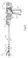
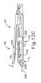
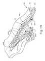
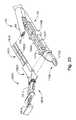
図1は、例示的な外科用ステープル留め及び切断器具(10)を表し、この器具は、ハンドル組立体(20)と、シャフト組立体(30)と、エンドエフェクタ(40)と、を含む。エンドエフェクタ(40)及びシャフト組立体(30)の遠位部分は、外科的処置を行うために、図1に描写されるような非関節動作状態で、トロカールカニューレを通って患者内の手術部位まで挿入するように寸法決めされている。単なる例示として、患者の腹部内に、患者の2本の肋骨の間に、又はその他の部位に、かかるトロカールを挿入してもよい。一部の状況では、器具(10)は、トロカールなしで使用される。例えば、エンドエフェクタ(40)及びシャフト組立体の遠位部分(30)を、開胸術又は他の種類の切開によって直接挿入することができる。本明細書では、「近位」及び「遠位」といった用語は、器具(10)のハンドル組立体(20)を握っている臨床医を基準として使用されていることを理解されたい。したがって、エンドエフェクタ(40)は、より近位にあるハンドル組立体(20)に対して遠位にある。便宜上、また説明を明確にするため、本明細書では「垂直」及び「水平」といった空間的な用語が、図面に対して使用されている点も更に認識されるであろう。しかしながら、外科器具は、多くの配向及び位置で使用されるものであり、これらの用語は、限定的かつ絶対的なものであることを意図するものではない。I. Exemplary Surgical Stapler FIG. 1 represents an exemplary surgical stapling and cutting instrument (10) that includes a handle assembly (20), a shaft assembly (30), and an end effector (40). ) And. The distal portion of the end effector (40) and shaft assembly (30) is operated through a trocar cannula in a non-articulated condition as depicted in FIG. 1 to perform a surgical procedure. Is dimensioned to be inserted up to. By way of example only, such a trocar may be inserted into the patient's abdomen, between the patient's two ribs, or elsewhere. In some situations, the instrument (10) is used without a trocar. For example, the end effector (40) and the distal portion (30) of the shaft assembly can be directly inserted by thoracotomy or other type of incision. It should be understood that the terms “proximal” and “distal” are used herein with reference to the clinician holding the handle assembly (20) of the instrument (10). Thus, the end effector (40) is distal to the more proximal handle assembly (20). It will be further appreciated that, for convenience and clarity of explanation, spatial terms such as “vertical” and “horizontal” are used herein with respect to the drawings. However, surgical instruments are used in many orientations and positions, and these terms are not intended to be limiting and absolute.
A.例示的なハンドル組立体及びシャフト組立体
図1〜2に示すように、本例のハンドル組立体(20)は、ピストルグリップ(22)、閉鎖トリガー(24)、及び発射トリガー(26)を含む。各トリガー(24、26)は、以下により詳細に記載されるように、ピストル把持部(22)に向かって、かつそれから離れるように選択的に枢動可能である。ハンドル組立体(20)は、アンビル解放ボタン(25)と、発射ビーム反転スイッチ(27)と、取り外し可能な電池パック(28)と、を更に備える。これらの構成要素についても、以下でより詳細に説明する。勿論、ハンドル組立体(20)は、上記したもののいずれかに加えて又はその代わりに様々な他の構成要素、特徴、及び動作性を有することができる。ハンドル組立体(20)の他の好適な構成は、本明細書の教示を考慮することで当業者には明らかであろう。A. Exemplary Handle Assembly and Shaft Assembly As shown in FIGS. 1-2, the handle assembly (20) of the present example includes a pistol grip (22), a closure trigger (24), and a firing trigger (26). . Each trigger (24, 26) is selectively pivotable toward and away from the pistol grip (22) as described in more detail below. The handle assembly (20) further comprises an anvil release button (25), a firing beam reversing switch (27), and a removable battery pack (28). These components are also described in more detail below. Of course, the handle assembly (20) may have various other components, features, and operability in addition to or instead of any of those described above. Other suitable configurations for the handle assembly (20) will be apparent to those skilled in the art in view of the teachings herein.
図1〜図3に示すように、本例のシャフト組立体(30)は、外側閉鎖管(32)、関節運動部(34)、及び閉鎖用リング(36)を備え、それは、更にエンドエフェクタ(40)に連結する。閉鎖チューブ(32)はシャフト組立体(30)の長さに沿って延在する。閉鎖リング(36)は、関節運動部(34)の遠位に位置付けられている。閉鎖管(32)及び閉鎖用リング(36)は、ハンドル組立体(20)に対して長手方向に並進するように構成されている。閉鎖チューブ(32)の長手方向並進運動は、関節運動部(34)を介して閉鎖リング(36)に伝達される。閉鎖管(32)及び閉鎖用リング(36)を長手方向に並進するのに使用できる例示の機構は、以下により詳細に記載される。 1-3, the shaft assembly (30) of the present example comprises an outer closure tube (32), an articulation portion (34), and a closure ring (36), which further includes an end effector. Connect to (40). The closure tube (32) extends along the length of the shaft assembly (30). The closure ring (36) is located distal to the articulation section (34). The closure tube (32) and the closure ring (36) are configured to translate longitudinally relative to the handle assembly (20). The longitudinal translation of the closure tube (32) is transmitted to the closure ring (36) via the articulation section (34). Exemplary mechanisms that can be used to translate the closure tube (32) and closure ring (36) longitudinally are described in more detail below.
関節運動部(34)は、シャフト組立体(30)の長手方向軸(LA)から所望の角度(α)で横方向へ離れるように、閉鎖リング(36)とエンドエフェクタ(40)を横方向に偏向させるよう操作可能である。エンドエフェクタ(40)は、そのようにして、所望の角度から又は他の理由のために、臓器の背後に到達するか又は組織に近付くことができる。一部の形態においては、関節運動部(34)は、単一の平面に沿ってエンドエフェクタ(40)を偏向させることができる。その他の一部の形態では、関節運動部(34)により、2つ以上の平面に沿ってエンドエフェクタを撓ませることができる。本例では、関節運動は、シャフト組立体(30)の近位端に位置する関節運動制御ノブ(35)によって制御される。ノブ(35)は、シャフト組立体(30)の長手方向軸(LA)に対して垂直な軸を中心として回転可能である。閉鎖用リング(36)及びエンドエフェクタ(40)は、ノブ(35)の回転に反応してシャフト組立体(30)の長手方向軸(LA)に垂直な軸の周りを枢動する。ほんの一例として、ノブ(35)が時計回りに回転すると、関節運動部(34)において閉鎖用リング(36)及びエンドエフェクタ(40)が対応して時計回りに枢動する。関節運動部(34)は、関節運動部(34)が真っ直ぐな構成であるか、又は関節運動構成であるかにかかわらず、閉鎖管(32)が閉鎖用リング(36)まで長手方向に並進するのを伝達するように構成されている。 The articulation portion (34) laterally moves the closure ring (36) and end effector (40) laterally away from the longitudinal axis (LA) of the shaft assembly (30) at a desired angle (α). It can be operated to deflect it. The end effector (40) can thus reach behind the organ or approach the tissue from a desired angle or for other reasons. In some configurations, the articulation portion (34) can deflect the end effector (40) along a single plane. In some other configurations, the end effector can be deflected along two or more planes by the articulation portion (34). In this example, articulation is controlled by an articulation control knob (35) located at the proximal end of the shaft assembly (30). The knob (35) is rotatable about an axis perpendicular to the longitudinal axis (LA) of the shaft assembly (30). The closure ring (36) and end effector (40) pivot about an axis perpendicular to the longitudinal axis (LA) of the shaft assembly (30) in response to rotation of the knob (35). By way of example only, when the knob (35) rotates clockwise, the closure ring (36) and the end effector (40) pivot correspondingly clockwise in the articulation (34). The articulation section (34) translates longitudinally the closure tube (32) to the closure ring (36) regardless of whether the articulation section (34) is straight or articulated. Configured to communicate.
一部の形態では、関節運動部(34)及び/又は関節運動制御ノブ(35)は、2014年8月28日に公開された「Surgical Instrument End Effector Articulation Drive with Pinion and Opposing Racks」と題する米国特許出願公開第2014/0243801号(この開示は、参照により本明細書に組み込まれる)の少なくとも一部の教示に従って、構成され操作できる。関節運動部(34)は、また、2014年6月25日に出願された「Articulation Drive Features for Surgical Stapler」と題する米国特許出願第14/314,125号(この開示は、参照により本明細書に組み込まれる)の少なくとも一部の教示に従って、及び/又は、以下の様々な教示に従って、構成され操作できる。関節運動部(34)及び関節動作ノブ(35)が取り得る他の好適な形態は、本明細書の教示を鑑みれば当業者には明らかになるであろう。 In some forms, the articulation section (34) and / or the articulation control knob (35) is a United States title entitled “Surgical Instrument End Effector Driving with Pinning and Opposing Racks” published August 28, 2014. It can be constructed and operated in accordance with the teachings of at least part of Patent Application Publication No. 2014/0243801, the disclosure of which is incorporated herein by reference. The articulation section (34) is also disclosed in US patent application Ser. No. 14 / 314,125, filed Jun. 25, 2014, entitled “Articulation Drive Features for Surgical Stapler”, the disclosure of which is hereby incorporated by reference. In accordance with at least some teachings) and / or according to the following various teachings. Other suitable forms that the articulation section (34) and the articulation knob (35) may take will be apparent to those skilled in the art in view of the teachings herein.
図1〜2に示すように、本例のシャフト組立体(30)は更に、回転ノブ(31)を含む。回転ノブ(31)は、シャフト組立体(30)の長手方向軸(LA)の周りを、ハンドル組立体(20)に対して、全シャフト組立体(30)及びエンドエフェクタ(40)を回転するように操作可能である。一部の形態では、回転ノブ(31)は、シャフト組立体(30)の長手方向軸(LA)の周りを、ハンドル組立体(20)に対して、シャフト組立体(30)及びエンドエフェクタ(40)の角度位置を選択的に係止するように操作可能である。例えば、回転ノブ(31)は、シャフト組立体(30)及びエンドエフェクタ(40)がシャフト組立体(30)の長手方向軸(LA)の周りをハンドル組立体(20)に対して回転可能である第1の長手方向位置と、シャフト組立体(30)及びエンドエフェクタ(40)がシャフト組立体(30)の長手方向軸線(LA)の周りを、ハンドル組立体(20)に対して回転できない第2の長手方向位置との間で並進可能である。当然のことながら、シャフト組立体(30)は、上記したもののいずれかに加えて又はその代わりに様々な他の構成要素、特徴、及び動作性を有することができる。あくまで一例として、シャフト組立体(30)の少なくとも一部は、2014年8月28日公開の「Surgical Instrument with Multi−Diameter Shaft」と題する米国特許出願公開第2014/0239038号の教示のうちの少なくともいくつかに従って構成されてもよい。シャフト組立体(30)の他の好適な構成は、本明細書の教示を鑑みれば当業者には明らかになるであろう。 As shown in FIGS. 1-2, the shaft assembly (30) of the present example further includes a rotation knob (31). The rotation knob (31) rotates the entire shaft assembly (30) and end effector (40) relative to the handle assembly (20) about the longitudinal axis (LA) of the shaft assembly (30). Is operable. In some forms, the rotary knob (31) is about the longitudinal axis (LA) of the shaft assembly (30) relative to the handle assembly (20) and the shaft assembly (30) and end effector ( 40) can be operated to selectively lock the angular position. For example, the rotary knob (31) allows the shaft assembly (30) and end effector (40) to rotate relative to the handle assembly (20) about the longitudinal axis (LA) of the shaft assembly (30). A first longitudinal position and the shaft assembly (30) and end effector (40) cannot rotate about the longitudinal axis (LA) of the shaft assembly (30) relative to the handle assembly (20). Translation between the second longitudinal position is possible. Of course, the shaft assembly (30) may have various other components, features, and operability in addition to or in place of any of those described above. By way of example only, at least a portion of the shaft assembly (30) may contain at least one of the teachings of US Patent Application Publication No. 2014/0239038 entitled “Surgical Instrument with Multi-Diameter Shaft” published August 28, 2014. It may be configured according to several. Other suitable configurations for the shaft assembly (30) will be apparent to those skilled in the art in view of the teachings herein.
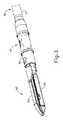
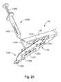
B.例示的なエンドエフェクタ
図1〜3にも示されているように、本例のエンドエフェクタ(40)は、下側ジョー(50)及び枢動可能なアンビル(60)を含む。アンビル(60)は、下側ジョー(50)の対応する湾曲スロット(54)に配置されている一対の一体的な、外側に延在するピン(66)を含む。ピン(66)及びスロット(54)を図5に示す。アンビル(60)は、開放位置(図2及び4に示す)と閉鎖位置(図1、3、及び7A〜7Bに示す)との間で、下側ジョー(50)に向かって、及びそれから離れるように、枢動可能である。「枢動可能」という用語(及び「枢動」を基体とした類義語)の使用は、必ずしも固定軸を中心とした枢動運動を必要とすると理解されるべきではない。例えば、本例において、アンビル(60)は、ピン(66)により画定される軸を中心に枢動し、このピンは、アンビル(60)が下側ジョー(50)に向かって動くと、下側ジョー(50)の湾曲スロット(54)に沿って摺動する。かかる形態では、枢動軸がスロット(54)によって画定された経路に沿って並進する一方で、アンビル(60)はその軸を中心として同時に枢動する。追加的にあるいは代替的に、まず枢動軸がスロット(54)に沿って摺動し、次いで枢動軸がスロット(54)に沿ってある一定の距離を摺動した後に、アンビル(60)が枢動軸を中心として枢動してもよい。そのような摺動/並進枢動運動は、「枢動」、「枢動する」「枢動の」、「枢動可能な」、「枢動している」などの用語内に包含されることを理解されたい。当然のことながら、一部の形態は、固定されたままである、かつスロット又はチャネルなどの内側を並進しない、軸を中心としたアンビル(60)の枢動運動を提供してもよい。B. Exemplary End Effector As also shown in FIGS. 1-3, the example end effector (40) includes a lower jaw (50) and a pivotable anvil (60). Anvil (60) includes a pair of integral, outwardly extending pins (66) disposed in corresponding curved slots (54) of lower jaw (50). Pin (66) and slot (54) are shown in FIG. The anvil (60) moves toward and away from the lower jaw (50) between an open position (shown in FIGS. 2 and 4) and a closed position (shown in FIGS. 1, 3, and 7A-7B). So that it is pivotable. The use of the term “pivotable” (and synonyms based on “pivot”) should not be understood as necessarily requiring a pivoting movement about a fixed axis. For example, in this example, the anvil (60) pivots about the axis defined by the pin (66), which pin is lowered when the anvil (60) moves toward the lower jaw (50). It slides along the curved slot (54) of the side jaw (50). In such a configuration, the pivot axis translates along the path defined by the slot (54) while the anvil (60) pivots simultaneously about that axis. Additionally or alternatively, the anvil (60) after the pivot axis first slides along the slot (54) and then the pivot axis slides a distance along the slot (54). May pivot about the pivot axis. Such sliding / translational pivoting movements are encompassed within terms such as “pivoting”, “pivoting”, “pivoting”, “pivotable”, “pivoting”, etc. Please understand that. Of course, some configurations may provide a pivoting movement of the anvil (60) about the axis that remains fixed and does not translate inside such as a slot or channel.
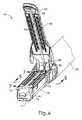
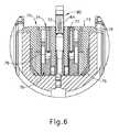
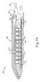
図5に最もわかりやすく示されるように、本例の下側ジョー(50)は、ステープルカートリッジ(70)を受容するように構成されているチャネル(52)を画定する。ステープルカートリッジ(70)はチャネル(52)に挿入することができ、エンドエフェクタ(40)を作動し、その後、ステープルカートリッジ(70)を取り外し、別のステープルカートリッジ(70)と交換することができる。したがって、下側ジョー(50)は、エンドエフェクタ(40)を作動するためのアンビル(60)と位置合わせされてステープルカートリッジ(70)を解放可能に保持する。一部の形態では、下側ジョー(50)は、2014年8月28日に公開された「Installation Features for Surgical Instrument End Effector Cartridge」と題する米国特許出願公開第2014/0239044号(この開示は、参照により本明細書に組み込まれる)の少なくとも一部の教示に従って構成され得る。下側ジョー(50)が取り得る他の好適な形態は、本明細書の教示を鑑みれば当業者には明らかとなるであろう。 As best seen in FIG. 5, the lower jaw (50) of the present example defines a channel (52) that is configured to receive a staple cartridge (70). The staple cartridge (70) can be inserted into the channel (52) and the end effector (40) can be activated, after which the staple cartridge (70) can be removed and replaced with another staple cartridge (70). Thus, the lower jaw (50) is aligned with an anvil (60) for actuating the end effector (40) to releasably hold the staple cartridge (70). In some forms, the lower jaw (50) is a U.S. Patent Application Publication No. 2014/0239044 entitled “Installation Features for Surgical Instrument End Effector Cartridge” published on August 28, 2014 (the disclosure is Which may be configured in accordance with at least some of the teachings of (incorporated herein by reference). Other suitable forms that the lower jaw (50) may take will be apparent to those skilled in the art in view of the teachings herein.
図4〜図6に最もよく示されるように、本例のステープルカートリッジ(70)はカートリッジ本体(71)と、カートリッジ本体(71)の下面に固着されたトレー(76)を備える。カートリッジ本体(71)の上面は、アンビル(60)が閉鎖位置にあるとき、組織を圧縮できるデッキ(73)を提示する。カートリッジ本体(71)は、長手方向に延在するチャネル(72)及び複数のステープルポケット(74)を更に画定する。ステープル(77)は、各ステープルポケット(74)内に位置付けられている。ステープルドライバ(75)はまた、各ステープルポケット(74)内で、対応するステープル(77)の下に、かつトレー(76)の上に位置付けられている。以下でより詳細に説明されるように、ステープルドライバ(75)はステープルポケット(74)内で上向きに並進運動するよう操作可能であり、これによりステープル(77)をステープルポケット(74)を通って上向きに駆動させ、アンビル(60)と係合させる。ステープルドライバ(75)は、楔形スレッド(78)により上向きに駆動され、この楔形スレッドはカートリッジ本体(71)とトレー(76)との間に捕捉されており、これがカートリッジ本体(71)を通って長手方向に並進運動する。楔形スレッド(78)は、一対の傾斜した角度のカム表面(79)を含み、それらは、ステープルドライバ(75)と係合し、それによって、楔形スレッド(78)がカートリッジ(70)を通って長手方向に並進するにつれてステープルドライバ(75)を上方に駆動するように構成されている。例えば、楔形スレッド(78)が図7Aに示すように近位位置にあるとき、ステープルドライバ(75)は下方位置にあり、ステープル(77)はステープルポケット(74)内に位置する。図7Bに示されるように、ナイフ部材(80)の並進運動によって楔型スレッド(78)が遠位位置に駆動されると、楔形スレッド(78)がステープルドライバ(75)を上向きに駆動し、これによりステープルを(77)ステープルポケット(74)から排出させ、アンビル(60)の下面(65)に形成されたステープル成形ポケット(64)内へと駆動する。よって、楔形スレッド(78)が水平寸法に沿って並進すると、ステープルドライバ(75)は垂直寸法に沿って並進する。 As best shown in FIGS. 4 to 6, the staple cartridge (70) of this example includes a cartridge body (71) and a tray (76) secured to the lower surface of the cartridge body (71). The top surface of the cartridge body (71) presents a deck (73) that can compress tissue when the anvil (60) is in the closed position. The cartridge body (71) further defines a longitudinally extending channel (72) and a plurality of staple pockets (74). Staples (77) are positioned in each staple pocket (74). A staple driver (75) is also positioned within each staple pocket (74), below the corresponding staple (77) and above the tray (76). As described in more detail below, the staple driver (75) is operable to translate upward within the staple pocket (74), thereby moving the staple (77) through the staple pocket (74). Drive upward and engage with anvil (60). The staple driver (75) is driven upward by a wedge-shaped thread (78), which is captured between the cartridge body (71) and the tray (76), which passes through the cartridge body (71). Translate in the longitudinal direction. The wedge-shaped thread (78) includes a pair of angled cam surfaces (79) that engage the staple driver (75) so that the wedge-shaped thread (78) passes through the cartridge (70). The staple driver (75) is configured to drive upward as it translates in the longitudinal direction. For example, when the wedge-shaped thread (78) is in the proximal position as shown in FIG. 7A, the staple driver (75) is in the down position and the staple (77) is in the staple pocket (74). As shown in FIG. 7B, when the wedge-shaped thread (78) is driven to the distal position by translation of the knife member (80), the wedge-shaped thread (78) drives the staple driver (75) upwards, This causes the staples to be ejected from the (77) staple pocket (74) and driven into the staple forming pocket (64) formed in the lower surface (65) of the anvil (60). Thus, as the wedge-shaped thread (78) translates along the horizontal dimension, the staple driver (75) translates along the vertical dimension.
ステープルカートリッジ(70)を多様な方法で変更できることを理解されたい。例えば、本例のステープルカートリッジ(70)は、チャネル(72)の一方の側に、長手方向に延在する2列のステープルポケット(74)を含み、チャネル(72)の他方の側に別の組の長手方向に延在する2列のステープルポケット(74)を含む。しかし、他の一部の形態では、ステープルカートリッジ(70)は、チャネル(72)の両側において3つ、1つ、又は他の数のステープルポケット(74)を含む。一部の変形例では、ステープルカートリッジ(70)は、その開示が参照により本明細書に組み込まれている2013年2月28日に出願の「Integrated Tissue Positioning and Jaw Alignment Features for Surgical Stapler」と題される米国特許出願第13/780,106号の教示の少なくとも一部に従って構成され、操作可能である。追加的にあるいは代替的に、ステープルカートリッジ(70)は、2014年8月28日に公開された「Installation Features for Surgical Instrument End Effector Cartridge」と題する米国特許出願公開第2014/0239044号(この開示は、参照により本明細書に組み込まれる)の少なくとも一部の教示に従って、構成され操作できる。ステープルカートリッジ(70)が取り得る他の好適な形態は、本明細書の教示を鑑みれば当業者には明らかとなるであろう。 It should be understood that the staple cartridge (70) can be modified in a variety of ways. For example, the staple cartridge (70) of the present example includes two rows of staple pockets (74) extending longitudinally on one side of the channel (72) and another on the other side of the channel (72). The set includes two rows of staple pockets (74) extending longitudinally. However, in some other forms, the staple cartridge (70) includes three, one, or other number of staple pockets (74) on either side of the channel (72). In some variations, the staple cartridge (70) is entitled “Integrated Tissue Positioning and Jaw Alignment Features for Surgical Stapler” filed on Feb. 28, 2013, the disclosure of which is incorporated herein by reference. Constructed and operable in accordance with at least part of the teachings of US patent application Ser. No. 13 / 780,106. Additionally or alternatively, a staple cartridge (70) is disclosed in U.S. Patent Application Publication No. 2014/0239044 entitled “Installation Features for Surgical Instrument End Effector Cartridge” published on August 28, 2014 (this disclosure is And can be constructed and operated in accordance with at least some of the teachings of which are incorporated herein by reference. Other suitable forms that the staple cartridge (70) may take will be apparent to those skilled in the art in view of the teachings herein.
図4で最もよくわかるように、本例のアンビル(60)は、長手方向に延在するチャネル(62)と、複数のステープル成形ポケット(64)とを備える。チャネル(62)は、アンビル(60)が閉鎖位置にあるとき、ステープルカートリッジ(70)のチャネル(72)と整列するように構成されている。ステープル成形ポケット(64)はそれぞれ、アンビル(60)が閉鎖位置にあるとき、ステープルカートリッジ(70)の対応するステープルポケット(74)の上に置かれるように位置付けられている。ステープル成形ポケット(64)は、ステープル(77)が組織を通してアンビル(60)の中に駆動されるとき、ステープル(77)の脚部を変形させるように構成されている。特に、ステープル成形ポケット(64)は、成形されたステープル(77)を組織内で固定するためにステープル(77)の脚部を曲げるように構成されている。アンビル(60)は、2014年8月28日に公開された「Integrated Tissue Positioning and Jaw Alignment Features for Surgical Stapler」と題する米国特許出願公開第2014/0239042号の教示のうち少なくとも一部、2014年8月28日に公開された「Jaw Closure Feature for End Effector of Surgical Instrument」と題する米国特許出願公開第2014/0239036号の教示のうち少なくとも一部、及び/又は、2014年8月28日に公開された「Staple Forming Features for Surgical Stapling Instrument」と題する米国特許出願公開第2014/0239037号の教示のうち少なくとも一部(これらの開示は、参照により本明細書に組み込まれる)に従って構築されてよい。アンビル(60)が取り得る他の好適な形態は、本明細書の教示を鑑みれば当業者には明らかとなるであろう。 As best seen in FIG. 4, the anvil (60) of the present example comprises a longitudinally extending channel (62) and a plurality of staple forming pockets (64). The channel (62) is configured to align with the channel (72) of the staple cartridge (70) when the anvil (60) is in the closed position. Each staple forming pocket (64) is positioned to be placed over a corresponding staple pocket (74) of the staple cartridge (70) when the anvil (60) is in the closed position. The staple forming pocket (64) is configured to deform the legs of the staple (77) as the staple (77) is driven through the tissue and into the anvil (60). In particular, the staple forming pocket (64) is configured to bend the legs of the staple (77) to secure the formed staple (77) in tissue. Anvil (60) is at least part of the teachings of US Patent Application Publication No. 2014/0239042 entitled “Integrated Tissue Positioning and Jaw Alignment Features for Surgical Stapler” published on August 28, 2014. At least part of the teachings of US Patent Application Publication No. 2014/0239036 entitled “Jaw Closure Feature for End Effect of Surgical Instrument” published on May 28, and / or published on August 28, 2014. “Staple Forming Features for Surgical Stapling Instrument” May be constructed according to at least some of the teachings of US Patent Application Publication No. 2014/0239037, the disclosures of which are incorporated herein by reference. Other suitable forms that anvil (60) may take will be apparent to those skilled in the art in view of the teachings herein.
本例では、ナイフ部材(80)は、エンドエフェクタ(40)を通って並進するように構成されている。図5及び7A〜7Bで最もよくわかるように、ナイフ部材(80)は発射ビーム(82)の遠位端に固定されており、この発射ビームは、シャフト組立体(30)の一部を通って延在する。図4及び図6で最もよくわかるように、ナイフ部材(80)は、アンビル(60)及びステープルカートリッジ(70)のチャネル(62、72)内に位置付けられている。ナイフ部材(80)は、ナイフ部材(80)がエンドエフェクタ(40)を通して遠位方向に並進するにつれて、アンビル(60)とステープルカートリッジ(70)のデッキ(73)との間で圧縮されている組織を切断するように構成されている、遠位側に示された切断縁部(84)を含む。上記し、かつ図7A〜図7Bに示すように、ナイフ部材(80)はまた、ナイフ部材(80)がエンドエフェクタ(40)を通して遠位に並進するにつれて楔形スレッド(78)を遠位に駆動し、それによってステープル(77)が組織を通してアンビル(60)に対して打ち込まれ、形成される。ナイフ部材(80)をエンドエフェクタ(40)を通して遠位に駆動するのに使用できる様々な機構については、以下に詳細に記載する。 In this example, the knife member (80) is configured to translate through the end effector (40). As best seen in FIGS. 5 and 7A-7B, the knife member (80) is secured to the distal end of the firing beam (82), which passes through a portion of the shaft assembly (30). Extend. As best seen in FIGS. 4 and 6, knife member (80) is positioned within channels (62, 72) of anvil (60) and staple cartridge (70). The knife member (80) is compressed between the anvil (60) and the deck (73) of the staple cartridge (70) as the knife member (80) translates distally through the end effector (40). It includes a cutting edge (84), shown distally, configured to cut tissue. As described above and shown in FIGS. 7A-7B, knife member (80) also drives wedge-shaped thread (78) distally as knife member (80) translates distally through end effector (40). As a result, staples (77) are driven and formed through the tissue and against the anvil (60). Various mechanisms that can be used to drive the knife member (80) distally through the end effector (40) are described in detail below.
一部の形態では、エンドエフェクタ(40)は、ステープルカートリッジ(70)が下側ジョー(50)に挿入されていないとき、ナイフ部材(80)がエンドエフェクタ(40)を通して遠位側に前進するのを防止するように構成されているロックアウト機構を含む。追加的にあるいは代替的に、エンドエフェクタ(40)は、1回作動された後のステープルカートリッジ(70)(例えば、全てのステープル(77)がそこから配備された)が下側ジョー(50)に挿入されているとき、ナイフ部材(80)がエンドエフェクタ(40)を通して遠位側に前進するのを防止するように構成されているロックアウト機構を含む。あくまで一例として、かかるロックアウト機構は、2014年8月28日に公開された「Lockout Feature for Movable Cutting Member of Surgical Instrument」と題する米国特許出願公開第2014/0239041号(この開示は、参照により本明細書に組み込まれる)の教示のうち少なくとも一部、及び/又は2014年6月25日に出願された「Method of Using Lockout Features for Surgical Stapler Cartridge」と題する米国特許出願第14/314,108号(この開示は、参照により本明細書に組み込まれる)の教示のうち少なくとも一部に従って構築されてよい。ロックアウト機構が取り得る他の好適な形態は、本明細書の教示を鑑みれば当業者には明らかとなるであろう。あるいは、エンドエフェクタ(40)は単に、そのようなロックアウト機構を省略してもよい。 In some forms, the end effector (40) is advanced distally through the end effector (40) when the staple cartridge (70) is not inserted into the lower jaw (50). Including a lockout mechanism configured to prevent Additionally or alternatively, the end effector (40) can be moved once after the staple cartridge (70) (e.g., all staples (77) are deployed therefrom) into the lower jaw (50). And a lockout mechanism configured to prevent the knife member (80) from being advanced distally through the end effector (40) when inserted into the device. By way of example only, such a lockout mechanism is disclosed in US Patent Application Publication No. 2014/0239041 entitled “Lockout Feature for Mobile Cutting Member of Surgical Instrument” published on August 28, 2014 (this disclosure is incorporated herein by reference). US patent application Ser. No. 14 / 314,108 entitled “Method of Using Lockout Features for Surgical Stapler Cartridge” filed Jun. 25, 2014 May be constructed according to at least some of the teachings of this disclosure, which is incorporated herein by reference. Other suitable forms that the lockout mechanism can take will be apparent to those skilled in the art in view of the teachings herein. Alternatively, the end effector (40) may simply omit such a lockout mechanism.
C.例示的なアンビル作動
本例において、アンビル(60)は、閉鎖用リング(36)をエンドエフェクタ(40)に対して遠位側に前進させることによって、下側ジョー(50)に向かって駆動される。閉鎖用リング(36)は、カム作用を介してアンビル(60)と協働し、エンドエフェクタ(40)に対する閉鎖用リング(36)の遠位への並進に反応してアンビル(60)を下側ジョー(50)に向かって駆動する。同様に、閉鎖用リング(36)は、アンビル(60)と協働し、エンドエフェクタ(40)に対する閉鎖用リング(36)の近位側への並進に反応してアンビル(60)を下側ジョー(50)から離れて開放することができる。あくまで一例として、閉鎖用リング(36)及びアンビル(60)は、2014年8月28日に公開された「Jaw Closure Feature for End Effector of Surgical Instrument」と題する米国特許出願公開第2014/0239036号(この開示は、参照により本明細書に組み込まれる)の教示のうち少なくとも一部に従って、及び/又は、2014年6月25日に出願された「Jaw Opening Feature for Surgical Stapler」と題する米国特許出願第14/314,108号(この開示は、参照により本明細書に組み込まれる)の教示のうち少なくとも一部に従って相互作用できる。エンドエフェクタ(40)に対して閉鎖用リング(36)を長手方向に並進するのに使用できる例示の機構は、以下により詳細に記載される。C. Exemplary Anvil Actuation In this example, the anvil (60) is driven toward the lower jaw (50) by advancing the closure ring (36) distally relative to the end effector (40). The The closure ring (36) cooperates with the anvil (60) via camming action to lower the anvil (60) in response to the distal translation of the closure ring (36) relative to the end effector (40). Drive towards the side jaws (50). Similarly, the closure ring (36) cooperates with the anvil (60) to lower the anvil (60) in response to the proximal translation of the closure ring (36) relative to the end effector (40). It can be released away from the jaw (50). By way of example only, a closure ring (36) and an anvil (60) are disclosed in U.S. Patent Application Publication No. 2014/0239036 entitled “Jaw Close Feature for End Effect of Surgical Instrument” published on August 28, 2014. This disclosure is in accordance with at least some of the teachings of this disclosure (incorporated herein by reference) and / or a US patent application entitled “Jaw Opening Feature for Surgical Stapler” filed June 25, 2014. 14 / 314,108, the disclosure of which is incorporated herein by reference, can interact according to at least some of the teachings. Exemplary mechanisms that can be used to translate the closure ring (36) longitudinally relative to the end effector (40) are described in more detail below.
上記したように、ハンドル組立体(20)は、ピストル把持部(22)と、閉鎖トリガー(22)とを含む。また、上記したように、アンビル(60)は、閉鎖用リング(36)の遠位前進に反応して下側ジョー(50)に向かって閉鎖される。本例において、閉鎖トリガー(24)は、閉鎖管(32)及び閉鎖用リング(36)を遠位側に駆動させるように、ピストル把持部(22)に向かって枢動可能である。本明細書の教示を考慮することで、ピストル把持部(22)に向かう閉鎖トリガー(24)の枢軸運動を、ハンドル組立体(20)に対する閉鎖管(32)及び閉鎖用リング(36)の遠位への並進に変換するのに使用され得る様々な好適な構成要素が、当業者には明らかであろう。閉鎖トリガー(24)は、アンビル(60)が、下側ジョー(50)に対して完全な閉鎖位置になるような完全な枢動状態に達するとき、ハンドル組立体(20)のロック機構は、トリガー(24)及び閉鎖管(32)の位置を係止し、それによってアンビル(60)を下側ジョー(50)に対して完全な閉鎖位置に係止する。これらの係止機構は、アンビル解放ボタン(25)の作動によって解放される。アンビル解放ボタン(25)は、ピストル把持部(22)をつかむ操作者の手の親指で作動されるように構成され、位置付けられている。言い換えると、操作者は、ピストル把持部(22)を片手でつかみ、閉鎖トリガー(24)を同じ手の1本又は2本以上の指で作動し、その後、同じ手によるピストル把持部(22)のつかみを解放する必要なく、アンビル解放ボタン(25)を同じ手の親指で作動することができる。本明細書の教示を考慮することで、アンビル(60)の作動に使用できる他の好適な機構が当業者に明らかとなるであろう。 As described above, the handle assembly (20) includes a pistol grip (22) and a closure trigger (22). Also, as described above, the anvil (60) is closed toward the lower jaw (50) in response to the distal advancement of the closing ring (36). In this example, the closure trigger (24) is pivotable toward the pistol grip (22) to drive the closure tube (32) and the closure ring (36) distally. In view of the teachings herein, the pivotal movement of the closure trigger (24) toward the pistol grip (22) is caused to move away from the closure tube (32) and the closure ring (36) relative to the handle assembly (20). A variety of suitable components that can be used to translate to translation to the position will be apparent to those skilled in the art. When the closure trigger (24) reaches full pivoting such that the anvil (60) is in a fully closed position relative to the lower jaw (50), the locking mechanism of the handle assembly (20) The position of the trigger (24) and closure tube (32) is locked, thereby locking the anvil (60) in the fully closed position relative to the lower jaw (50). These locking mechanisms are released by actuation of the anvil release button (25). The anvil release button (25) is configured and positioned to be actuated by the thumb of the operator's hand grabbing the pistol grip (22). In other words, the operator grasps the pistol grip (22) with one hand, operates the closing trigger (24) with one or more fingers of the same hand, and then the pistol grip (22) with the same hand. The anvil release button (25) can be actuated with the thumb of the same hand without having to release the grip. In view of the teachings herein, other suitable mechanisms that can be used to operate the anvil (60) will be apparent to those skilled in the art.
D.発射ビームの例示的作動
本発明の例では、器具(10)は、発射ビーム(82)の電動制御を提供する。特に、器具(10)は、発射トリガー(26)のピストル把持部(22)に向かう枢動に応答して発射ビーム(82)を遠位に駆動するように構成された、電動構成要素を備える。一部の形態では、モーター(図示せず)がピストル把持部(22)内に含まれ、電池パック(28)から電力を受信する。このモーターは、モーターの駆動シャフトの回転運動を、発射ビーム(82)の線形移動に変換する伝送組立体(図示せず)に連結される。一部のこのような形態では、アンビル(60)が下側ジョー(50)に対して完全閉鎖位置にあるとき、発射ビーム(82)は遠位に前進しかできない。図7A〜7Bを参照して上述されるように、発射ビーム(82)が遠位に前進して組織を切断し、ステープル(77)を駆動した後、発射ビーム(82)用の駆動組立体は、自動的に反転し、発射ビーム(82)を近位に後退位置に戻すように駆動できる(例えば、図7Bに示される位置から図7Aに示される位置まで戻す)。あるいは、操作者は、発射ビーム(82)用の駆動組立体を反転して発射ビーム(82)を近位位置に後退できる、発射ビーム反転スイッチ(27)を作動してよい。本例のハンドル組立体(20)は、機械的脱出をもたらすように操作可能であり、操作者が手動で発射ビーム(82)を近位に後退させることを可能にする(例えば、発射ビーム(82)が遠位位置にある間に電力損失した場合など)、脱出機構(21)を更に備える。D. Exemplary Operation of the Firing Beam In the example of the present invention, the instrument (10) provides motorized control of the firing beam (82). In particular, the instrument (10) comprises a motorized component configured to drive the firing beam (82) distally in response to pivoting of the firing trigger (26) toward the pistol grip (22). . In some forms, a motor (not shown) is included in the pistol grip (22) and receives power from the battery pack (28). The motor is coupled to a transmission assembly (not shown) that converts the rotational movement of the motor drive shaft into a linear movement of the firing beam (82). In some such configurations, the firing beam (82) can only be advanced distally when the anvil (60) is in a fully closed position relative to the lower jaw (50). The drive assembly for firing beam (82) after firing beam (82) has been advanced distally to cut tissue and drive staple (77), as described above with reference to FIGS. 7A-7B. Can be automatically reversed and driven to return the firing beam (82) proximally to the retracted position (eg, from the position shown in FIG. 7B to the position shown in FIG. 7A). Alternatively, the operator may activate a firing beam reversing switch (27) that can reverse the drive assembly for the firing beam (82) to retract the firing beam (82) to a proximal position. The handle assembly (20) of the present example is operable to provide mechanical escape and allows an operator to manually retract the firing beam (82) proximally (eg, the firing beam ( 82) further comprises an escape mechanism (21), such as when power is lost while in the distal position).
あくまで一例として、発射ビーム(82)の電動化作動をもたらすように操作可能な機構は、2012年7月3日に発行された「Motor−Driven Surgical Instrument」と題する米国特許第8,210,411号(この開示は、参照により本明細書に組み込まれる)の教示のうち少なくとも一部に従って、構成され、操作することができる。別の単なる例示例として、発射ビーム(82)の電動化作動をもたらすように操作可能な機構は、2013年6月4日に発行された「Motor−Driven Surgical Cutting Instrument with Electric Actuator Directional Control Assembly」と題する米国特許第8,453,914号(この開示は、参照により本明細書に組み込まれる)の教示のうち少なくとも一部に従って、構成され、操作することができる。更に別の単なる例示例として、発射ビーム(82)の電動化作動をもたらすように操作可能な機構は、2014年3月26日に出願された「Surgical Instrument Comprising a Sensor System」と題する米国特許出願第14/226,142号(この開示は、参照により本明細書に組み込まれる)の教示のうち少なくとも一部に従って、構成され、操作することができる。 By way of example only, a mechanism operable to provide motorized actuation of the launch beam (82) is disclosed in US Pat. No. 8,210,411 entitled “Motor-Driven Surgical Instrument” issued July 3, 2012. (The disclosure of which is incorporated herein by reference) may be constructed and operated in accordance with at least some of the teachings of the present disclosure. As another mere illustrative example, a mechanism operable to provide motorized actuation of the launch beam (82) is the “Motor-Driving Surgical Cutting Instrument Electric Control Assembler” issued June 4, 2013. US Pat. No. 8,453,914, the disclosure of which is incorporated herein by reference, may be constructed and operated in accordance with at least some of the teachings. By way of further example only, a mechanism operable to provide motorized actuation of the launch beam (82) is a US patent application entitled “Surgery Instrument Compiling a Sensor System” filed March 26, 2014. No. 14 / 226,142, the disclosure of which is incorporated herein by reference, may be constructed and operated in accordance with at least some of the teachings.
発射ビーム(82)の電動化をもたらすために使用できるその他好適な構成要素、特徴部、及び構成は、本明細書の教示を鑑みれば当業者には明らかになるであろう。また、他の形態において、発射ビーム(82)のマニュアル駆動が提供され、モーターが省かれてもよいことも理解されたい。あくまで一例として、発射ビーム(82)は、本明細書で引用されるその他の参照文献の教示のうち少なくとも一部に従って手動で作動することができる。 Other suitable components, features, and configurations that can be used to provide motorization of the firing beam (82) will be apparent to those skilled in the art in view of the teachings herein. It should also be understood that in other configurations, manual drive of the firing beam (82) may be provided and the motor may be omitted. By way of example only, the firing beam (82) can be manually actuated according to at least some of the teachings of other references cited herein.
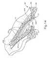
図8は、組織(90)を通じた1回のストロークを通して作動されたエンドエフェクタ(40)を示している。示されるように、切断縁部(84)(図8では不明瞭)は、組織(90)を切断したが、ステープルドライバ(75)は、切断縁部(84)が作り出した切断線の各側で、組織(90)を通してステープル(77)の2本の交互の列を駆動した。この例では、全てのステープル(77)が切断線とほぼ平行に向いているが、ステープル(77)は、任意の好適な向きで位置付けされ得る点を理解されたい。本例では、第1のストロークが完了した後にエンドエフェクタ(40)をトロカールから引き抜き、使用済みのステープルカートリッジ(70)を新しいステープルカートリッジ(70)と交換し、その後、エンドエフェクタ(40)を再びトロカールを通じて挿入して、ステープル留めする部位に到達させて更なる切断及びステープル留めを行う。所望の量の切断及びステープル(77)が与えられるまで、このプロセスを繰り返すことができる。トロカールを通じた挿入及び抜脱を助けるためにはアンビル(60)を閉鎖する必要があり、ステープルカートリッジ(70)の交換を助けるためにはアンビル(60)を開放する必要がある。 FIG. 8 shows the end effector (40) actuated through a single stroke through the tissue (90). As shown, the cutting edge (84) (unclear in FIG. 8) cut the tissue (90), but the staple driver (75) is on each side of the cutting line created by the cutting edge (84). The two alternating rows of staples (77) were driven through the tissue (90). In this example, all staples (77) are oriented generally parallel to the cutting line, but it should be understood that staples (77) may be positioned in any suitable orientation. In this example, after the first stroke is completed, the end effector (40) is withdrawn from the trocar, the used staple cartridge (70) is replaced with a new staple cartridge (70), and then the end effector (40) is again removed. Insert through the trocar and reach the site to be stapled for further cutting and stapling. This process can be repeated until the desired amount of cut and staple (77) is provided. The anvil (60) needs to be closed to aid insertion and removal through the trocar, and the anvil (60) needs to be opened to help replace the staple cartridge (70).
各作動ストロークの間に、ステープル(77)が組織に貫通して打ち込まれるのとほぼ同時に、切断縁部(84)が組織を切断することができる点を理解されたい。本例において、切断縁部(84)は、ステープル(77)の駆動動作よりもごくわずかに遅れて進むので、ステープル(47)は、切断縁部(84)が組織の同じ領域を通過する直前に組織を通して駆動されるが、この順序を逆にすることができる点、又は、切断縁部(84)が、隣り合うステープルと直接的に一緒に動いてもよい点を理解されたい。図8は、2層(92、94)の組織(90)で作動しているエンドエフェクタ(40)を示しているが、エンドエフェクタ(40)は、1層の組織(90)、又は2層(92、94)を超える組織を通じて作動され得る点を理解されたい。また、切断縁部(84)が形成する切断線に隣接するステープル(77)の成形及び位置決めにより、切断線において組織を実質的にシールすることができ、これにより、切断線での出血及び/又は他の体液の漏出を低減又は防止することができる点も理解されたい。更にまた、図8は、2つの概ね平坦で並置した組織の平面層(92、94)において作動されているエンドエフェクタ(40)を示すが、エンドエフェクタ(40)は、環状構造、例えば血管、消化管のセクションなどにわたって作動され得ることを理解されたい。図8は、したがって、エンドエフェクタ(40)についての意図された使用におけるなんらかの制限を示すものとして見られるべきではない。器具(10)を使用することができる様々な適当な状況及び手術は、本明細書の教示を鑑みれば当業者には明らかとなるであろう。 It should be understood that during each actuation stroke, the cutting edge (84) can cut the tissue at approximately the same time as the staple (77) is driven through the tissue. In this example, the cutting edge (84) advances very slightly behind the drive operation of the staple (77) so that the staple (47) is just before the cutting edge (84) passes through the same region of tissue. It should be understood that this order can be reversed, or the cutting edge (84) may move directly with the adjacent staples. FIG. 8 shows the end effector (40) operating with two layers (92, 94) of tissue (90), but the end effector (40) may be one layer of tissue (90) or two layers. It should be understood that it can be activated through more than (92,94) tissue. Also, the shaping and positioning of the staple (77) adjacent to the cutting line formed by the cutting edge (84) can substantially seal the tissue at the cutting line, thereby allowing bleeding and / or at the cutting line. It should also be understood that leakage of other body fluids can be reduced or prevented. Furthermore, FIG. 8 shows the end effector (40) being operated in two generally flat juxtaposed planar layers (92, 94) of tissue, the end effector (40) being an annular structure, such as a blood vessel, It should be understood that it can be operated over sections of the digestive tract and the like. FIG. 8 should therefore not be viewed as showing any limitations on the intended use for the end effector (40). Various suitable situations and procedures in which the instrument (10) can be used will be apparent to those skilled in the art in view of the teachings herein.
器具(10)の任意の他の構成要素又は機構は、本明細書に引用される様々な参照文献のうちいずれかに従って構成され、操作可能であることも理解されたい。器具(10)に行うことができる更なる例示的な改変例について以下により詳細に記載する。以下の教示を器具(10)に組み込むことができる様々な適当な方法が当業者には明らかであろう。同様に、以下の教示を本明細書で引用された参考文献の様々な教示と組み合わせることができる様々な好適な方法が当業者には明らかであろう。したがって、以下の教示が、本明細書に引用される様々な参考文献で教示されている様々な器具に容易に組み入れることができることが理解されよう。また、以下の教示は、本明細書に引用される参考文献に教示される器具(10)又は装置に限定されない点も理解されたい。以下の教示は、外科用ステープラとして分類されない器具を含む他の様々な種類の器具に容易に応用することができる。以下の教示を適用することができる他の様々な適当な装置及び状況は、本明細書の教示を鑑みれば当業者には明らかとなるであろう。 It should also be understood that any other component or mechanism of the instrument (10) can be constructed and operated according to any of the various references cited herein. Further exemplary modifications that can be made to the instrument (10) are described in more detail below. Various suitable ways in which the following teachings can be incorporated into the instrument (10) will be apparent to those skilled in the art. Similarly, various suitable ways in which the following teachings can be combined with the various teachings of the references cited herein will be apparent to those skilled in the art. Thus, it will be appreciated that the following teachings can be readily incorporated into the various devices taught in the various references cited herein. It should also be understood that the following teachings are not limited to the instrument (10) or apparatus taught in the references cited herein. The following teachings can be readily applied to various other types of instruments, including instruments that are not classified as surgical staplers. Various other suitable devices and circumstances to which the following teachings can be applied will be apparent to those skilled in the art in view of the teachings herein.
II.外科用ステープラ用の例示的な支持具
上記のように、場合によっては、ステープル(77)によってもたらされる組織(90)の機械的締結を補強するため、エンドエフェクタ(40)に支持材料を備えることが望ましい場合がある。かかる支持具は、適用したステープル(77)が組織(90)から引き抜かれるのを防ぐことができ、ステープル(77)の適用部位又はその付近の組織(90)が裂けるリスクを別の方法で低減することができる。ステープル(77)のラインに構造的支持及び一体性もたらすことに加え、又はそれに代わるものとして、支持具は、空隙又は間隙の充填、治療薬の投与などのその他様々な種類の効果、及び/又は別の効果をもたらすことができる。場合によっては、支持具は、ステープルカートリッジ(70)のデッキ(73)上に提供され得る。いくつかの別の場合では、支持具は、ステープルカートリッジ(70)に面するアンビル(60)の表面上に提供され得る。第1支持具がステープルカートリッジ(70)のデッキ(73)上に提供され得る一方で、第2支持具が同じエンドエフェクタ(40)のアンビル(60)上に提供され得ることも理解されよう。支持具が取り得る様々な形態の例を、以下により詳細に記載する。支持具がステープルカートリッジ(70)又はアンビル(60)に固定され得る様々な方法も、以下により詳細に記載される。II. Exemplary Support for Surgical Stapler As described above, in some cases, the end effector (40) is provided with a support material to reinforce the mechanical fastening of the tissue (90) provided by the staple (77). May be desirable. Such a support can prevent the applied staple (77) from being pulled out of the tissue (90) and otherwise reduces the risk of tearing the tissue (90) at or near the application site of the staple (77). can do. In addition to or in lieu of providing structural support and integrity to the line of staples (77), the support may include various other types of effects, such as filling voids or gaps, administering therapeutic agents, and / or Another effect can be brought about. In some cases, the support may be provided on the deck (73) of the staple cartridge (70). In some other cases, the support may be provided on the surface of the anvil (60) facing the staple cartridge (70). It will also be appreciated that the first support can be provided on the deck (73) of the staple cartridge (70) while the second support can be provided on the anvil (60) of the same end effector (40). Examples of the various forms that the support can take are described in more detail below. Various methods by which the support can be secured to the staple cartridge (70) or anvil (60) are also described in more detail below.
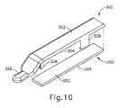
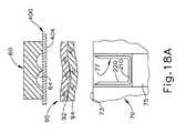
A.外科用ステープラ用の支持具例示的な構成
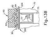
図9は、基本的構成の例示的な支持具組立体(100)を示す。この例の支持具組立体(100)は、支持具本体(102)と、上側接着層(104)と、下側接着層(106)と、を備える。本例において、支持具本体(102)は、ステープル(77)のラインを構造的に支持するように構成されている、強くはあるが可撓性の材料を含む。追加的にあるいは代替的に、支持具本体(102)は、例えば、血液を凝固させ、かつ組織(90)に沿って切断及び/又はステープル留めされた手術部位における出血を低減させるのを助ける、フィブリンなどの止血薬を含む材料を含んでよい。A. FIG. 9 illustrates an exemplary support assembly (100) in a basic configuration. The support assembly (100) of this example includes a support body (102), an upper adhesive layer (104), and a lower adhesive layer (106). In this example, the support body (102) comprises a strong but flexible material configured to structurally support the lines of staples (77). Additionally or alternatively, the support body (102) helps to reduce bleeding at, for example, a surgical site that has been coagulated and cut and / or stapled along the tissue (90). Materials including hemostatic agents such as fibrin may be included.
別の単なる例示例として、支持具本体(102)は、血液を凝固させ、かつ手術部位における出血量を低減させるのを支持具本体(102)が助けることができるように、他の添加剤又はトロンビンなどの止血薬を含んでもよい。かかる添加物の止血能力はまた、接着剤及びシーラントとしてのかかる添加物の使用にも寄与し得る。これらの薬剤は、例えば、かかる血液を取り囲む組織がくっつき合うこと可能にする手術部位での血液を凝固させるのを補助し得、かつステープル留めされた組織部位に沿って漏れることを防止し得る。支持具本体(102)に組み入れることができる他の添加剤又は試薬としては、更に薬液又はマトリックス成分を挙げることができるがこれらに限定されない。あくまで一例として、支持具本体(102)は、天然の又は遺伝子操作されている吸収性ポリマー又は合成吸湿性ポリマー又はそれらの混合物を含むことができる。天然の又は遺伝操作された吸収性ポリマーの単に例示的な例は、蛋白質、多糖及びその組み合わせである。使用することができる蛋白質の単に例示的な例としては、プロトロンビン、トロンビン、フィブリノーゲン、フィブリン、フィブロネクチン、ヘパリナーゼ、第X/Xa因子、第VII/VIIa因子、第IX因子/IXa、第XI/XIa因子、第XII/XIIa因子、組織因子、バトロキソビン、アンクロド、エカリン、フォンビルブラント因子、コラーゲン、エラスチン、アルブミン、ゼラチン、血小板面糖蛋白質、バソプレシン、バソプレシンアナログ、エピネフリン、セレクチン、プロコアギュラントベノム(procoagulant venom)、プラスミノーゲン活性化因子抑制因子、血小板活性化剤、止血活性を有する合成ペプチド及び/又はその組み合わせがある。また多糖には、セルロース、アルキルセルロース、例えば、メチルセルロース、アルキルヒドロキシアルキルセルロース、ヒドロキシアルキルセルロース、セルロース硫酸、カルボキシメチルセルロースの塩、カルボキシメチルセルロース、カルボキシエチルセルロース、キチン、カルボキシメチルキチン、ヒアルロン酸、ヒアルロン酸の塩、アルギネート、アルギン酸、アルギン酸プロピレングリコール、グリコーゲン、デキストラン、デキストラン硫酸、カードラン、ペクチン、プルラン、キサンタン、コンドロイチン、コンドロイチン硫酸類、カルボキシメチルデキストラン、カルボキシメチルキトサン、キトサン、ヘパリン、ヘパリン硫酸、ヘパラン、ヘパラン硫酸、デルマタン硫酸、ケラタン硫酸、カラギーナン類、キトサン、デンプン、アミロース、アミロペクチン、ポリ−N−グルコサミン、ポリマンヌロン酸、ポリグルクロン酸、ポリグルロン酸、及び上記のいずれかの誘導体を挙げることができる。合成吸収性ポリマーの例は、脂肪族ポリエステルポリマー、コポリマー、及び/又はこれらの組み合わせである。脂肪族ポリエステルは、典型的には、乳酸、ラクチド(L−、D−、メソ形、及びD、L混合物を含む)、グリコール酸、グリコリド、ε−カプロラクトン、p−ジオキサノン(1,4−ジオキサン−2−オン)、及びトリメチレンカーボネート(1,3−ジオキサン−2−オン)を含むが、これらに限定されないモノマーの開環重合において合成される。医療用流体又はマトリックスで使用することができる他の好適な化合物、材料、物質などは、本明細書の教示を考えて、当業者には明白であろう。 As another mere illustrative example, the support body (102) may be coagulated with other additives or to allow the support body (102) to coagulate blood and reduce the amount of bleeding at the surgical site. Hemostatic agents such as thrombin may be included. The hemostatic ability of such additives can also contribute to the use of such additives as adhesives and sealants. These agents may, for example, help coagulate blood at the surgical site that allows the tissues surrounding such blood to stick together and prevent leakage along the stapled tissue site. Other additives or reagents that can be incorporated into the support body (102) can further include, but are not limited to, chemicals or matrix components. By way of example only, the support body (102) may comprise a natural or genetically engineered absorbent polymer or a synthetic hygroscopic polymer or mixtures thereof. Only illustrative examples of natural or genetically engineered absorbable polymers are proteins, polysaccharides and combinations thereof. Just illustrative examples of proteins that can be used include prothrombin, thrombin, fibrinogen, fibrin, fibronectin, heparinase, factor X / Xa, factor VII / VIIa, factor IX / IXa, factor XI / XIa , Factor XII / XIIa, tissue factor, batroxobin, ancrod, ecarin, von Willebrand factor, collagen, elastin, albumin, gelatin, platelet surface glycoprotein, vasopressin, vasopressin analog, epinephrine, selectin, procoagulant venom ), Plasminogen activator inhibitor, platelet activator, synthetic peptide having hemostatic activity and / or combinations thereof. Polysaccharides include cellulose, alkyl cellulose, such as methyl cellulose, alkyl hydroxyalkyl cellulose, hydroxyalkyl cellulose, cellulose sulfate, carboxymethyl cellulose salt, carboxymethyl cellulose, carboxyethyl cellulose, chitin, carboxymethyl chitin, hyaluronic acid, hyaluronic acid salt. , Alginate, alginic acid, propylene glycol alginate, glycogen, dextran, dextran sulfate, curdlan, pectin, pullulan, xanthan, chondroitin, chondroitin sulfates, carboxymethyldextran, carboxymethyl chitosan, chitosan, heparin, heparin sulfate, heparan, heparan sulfate , Dermatan sulfate, keratan sulfate, carrageenans, chitosan, de Pung, amylose, amylopectin, poly -N- glucosamine, polymannuronic acid, polyglucuronic acid, and polyguluronic acid and derivatives of any of the above. Examples of synthetic absorbent polymers are aliphatic polyester polymers, copolymers, and / or combinations thereof. Aliphatic polyesters typically include lactic acid, lactide (including L-, D-, meso forms, and mixtures of D, L), glycolic acid, glycolide, ε-caprolactone, p-dioxanone (1,4-dioxane). -2-one), and trimethylene carbonate (1,3-dioxan-2-one). Other suitable compounds, materials, substances, etc. that can be used in the medical fluid or matrix will be apparent to those skilled in the art in view of the teachings herein.
あるいは、支持具本体(102)は、繊維パッド、発泡体、メッシュ、織物、並びに/又は、接着剤及び/若しくは他種の薬液を含むことができる別の構造体を含むことができる。追加的にあるいは代替的に、支持具本体(102)は単純に、メッシュ、織物、及び/又は、組織(90)を通して適用されたステープル(77)のラインに構造的支持又は一体性をもたらすように構築される、いくつかの別の構造体を備えてよい。このような材料及び構造体は比較的薄くてよく、場合によっては、実質的に非圧縮性であってよい。あくまで更なる例として、支持具本体(102)は、2012年9月27日に公開された「Tissue Thickness Compensator Comprising Controlled Release and Expansion」と題する米国特許出願公開第2012/0241493号(この開示は、参照により本明細書に組み込まれる)、2013年3月21日に公開された「Surgical Instrument and Buttress Material」と題する米国特許出願公開第2013/0068816号(この開示は、参照により本明細書に組み込まれる)、2013年3月14日に公開された「Surgical Instrument with Fluid Fillable Buttress」と題する米国特許出願公開第2013/0062391号(この開示は、参照により本明細書に組み込まれる)、2013年3月21日に公開された「Fibrin Pad Matrix with Suspended Heat Activated Beads of Adhesive」と題する米国特許出願公開第2013/0068820号(この開示は、参照により本明細書に組み込まれる)、2013年4月4日に公開された「Attachment of Surgical Staple Buttress to Cartridge」と題する米国特許出願公開第2013/0082086号(この開示は、参照により本明細書に組み込まれる)、2013年2月14日に公開された「Device for Applying Adjunct in Endoscopic Procedure」と題する米国特許出願公開第2013/0037596号(この開示は、参照により本明細書に組み込まれる)、2013年3月14日に公開された「Resistive Heated Surgical Staple Cartridge with Phase Change Sealant」と題する米国特許出願公開第2013/0062393号(この開示は、参照により本明細書に組み込まれる)、2013年3月28日に公開された「Surgical Staple Assembly with Hemostatic Feature」と題する米国特許出願公開第2013/0075446号(この開示は、参照により本明細書に組み込まれる)、2013年3月14日に公開された「Surgical Staple Cartridge with Self−Dispensing Staple Buttress」と題する米国特許出願公開第2013/0062394号(この開示は、参照により本明細書に組み込まれる)、2013年3月28日に公開された「Anvil Cartridge for Surgical Fastening Device」と題する米国特許出願公開第2013/0075445号(この開示は、参照により本明細書に組み込まれる)、2013年3月28日に公開された「Adjunct Therapy for Applying Hemostatic Agent」と題する米国特許出願公開第2013/0075447号(この開示は、参照により本明細書に組み込まれる)、及び/又は、2013年10月3日に公開された「Tissue Thickness Compensator Comprising a Plurality of Medicaments」と題する米国特許出願公開第2013/0256367号(この開示は、参照により本明細書に組み込まれる)の教示のうち少なくとも一部に従って、構築されてよい。 Alternatively, the support body (102) can include fiber pads, foams, meshes, fabrics, and / or other structures that can include adhesives and / or other types of chemicals. Additionally or alternatively, the support body (102) simply provides structural support or integrity to the lines of staples (77) applied through the mesh, fabric, and / or tissue (90). May be provided with several other structures. Such materials and structures can be relatively thin and in some cases can be substantially incompressible. By way of further example only, the support body (102) is a US Patent Application Publication No. 2012/0241493 entitled “Tissue Thickness Compensator Comprising Controlled Release and Expansion” published on September 27, 2012 (this disclosure U.S. Patent Application Publication No. 2013/0068816 entitled “Surgical Instrument and Buttress Material” published March 21, 2013, the disclosure of which is incorporated herein by reference. Published on March 14, 2013, “Surgical Instrument with Fluid File Buttress” US Patent Application Publication No. 2013/0062391 entitled “s” (the disclosure of which is incorporated herein by reference), “Fibrin Pad Matrix with Suspended Beads of Adhesive” published March 21, 2013. US Patent Application Publication No. 2013/0068820, the disclosure of which is incorporated herein by reference, US Patent Application entitled “Attachment of Surgical Staples to Cartridge” published April 4, 2013 Publication 2013/0082086 (the disclosure of which is incorporated herein by reference) published on February 14, 2013, “Device for Appl”. US Patent Application Publication No. 2013/0037596 entitled “ing Adjunct in Endoscopic Procedure” (the disclosure of which is incorporated herein by reference), “Resistive Heated Stable Protective Purge” published on March 14, 2013. United States Patent Application Publication No. 2013/0062393 entitled "Change Sealant" (the disclosure of which is incorporated herein by reference), United States entitled "Surgical Staple Assemblage With Heartfeature" published March 28, 2013. Patent application publication 2013/0075446 (the disclosure of which is incorporated herein by reference) ), U.S. Patent Application Publication No. 2013/0062394, published March 14, 2013, entitled “Surgical Staple Cartridge with Self-Dispensing Staple Buttress”, the disclosure of which is incorporated herein by reference. US Patent Application Publication No. 2013/0075445 entitled “Anvil Cartridge for Surgical Fastening Device” published on March 28, 2013, the disclosure of which is incorporated herein by reference, on March 28, 2013 Published US Patent Application Publication No. 2013/0075447 (“Adjunctive Therapy for Applying Hemostatic Agent”) The disclosure is incorporated herein by reference) and / or US Patent Application Publication No. 2013/0256367 entitled “Tissue Thickness Compensator Compiling a Plurality of Medicines” published on Oct. 3, 2013 (this The disclosure may be constructed in accordance with at least some of the teachings of (incorporated herein by reference).
本例において、支持具本体(102)は、Ethicon US,LLC.のVICRYL(登録商標)(ポリグラクチン910)材料の織メッシュを含む。VICRYL(登録商標)織メッシュは、それぞれグリコール酸及び乳酸由来の合成吸収性コポリマーであるグリコリド及びラクチドから調製される。この緊密に織られたメッシュは、不活性、非抗原性、非発熱性であり、吸収中の組織反応が軽度であるとわかっている、VICRYL(登録商標)合成吸収性縫合糸に使用されている繊維と同一の構成である、コーティングと染色がなされていない繊維から調製される。VICRYL(登録商標)織メッシュは、治癒過程中に一時的な支持をもたらす支持具としての使用を対象としている。あるいは、任意のその他好適な材料又は材料の組み合わせを、VICRYL(登録商標)材料に加えて、又はこれに代わるものとして使用し、支持具本体(102)を形成してよい。 In this example, the support body (102) is Ethicon US, LLC. VICRYL® (polyglactin 910) material woven mesh. VICRYL® woven mesh is prepared from glycolide and lactide, which are synthetic absorbent copolymers derived from glycolic acid and lactic acid, respectively. This tightly woven mesh is used in VICRYL® synthetic absorbable sutures that are inert, non-antigenic, non-pyrogenic and known to have a mild tissue reaction during absorption. Prepared from uncoated and dyed fibers of the same construction as the existing fibers. VICRYL® woven mesh is intended for use as a support that provides temporary support during the healing process. Alternatively, any other suitable material or combination of materials may be used in addition to or as an alternative to the VICRYL® material to form the support body (102).
支持具本体(102)がメッシュとして形成される形態では、様々な種類のメッシュ形状を使用できると理解されたい。あくまで一例として、支持具本体(102)は、織メッシュ、編メッシュ、又は縦編メッシュとして形成されてよい。支持具本体(102)がメッシュとして形成されるか否かに関わらず、一部の例では、支持具本体(102)は多孔性である。以下により詳細に説明するように、接着層(104、106)は支持具本体(102)上に提供され、支持具本体(102)をアンビル(60)の下面(65)又はステープルカートリッジ(70)のデッキ(73)に接着できる。支持具本体(102)が多孔性であるいくつかの形態では、接着層(104、106)を形成する材料は、支持具本体(102)を通過し、接着層(104、106)が配置されている表面の反対側の支持具本体(102)の外表面に到達できる。 It should be understood that various types of mesh shapes can be used in the form in which the support body (102) is formed as a mesh. By way of example only, the support body (102) may be formed as a woven mesh, a knitted mesh, or a warp knitted mesh. Regardless of whether the support body (102) is formed as a mesh, in some examples, the support body (102) is porous. As will be described in more detail below, an adhesive layer (104, 106) is provided on the support body (102), and the support body (102) is attached to the lower surface (65) of the anvil (60) or the staple cartridge (70). Can be attached to the deck (73). In some forms where the support body (102) is porous, the material forming the adhesive layer (104, 106) passes through the support body (102) and the adhesive layer (104, 106) is disposed. Can reach the outer surface of the support body (102) opposite the facing surface.
あくまで一例として、以下により詳細に説明するように、上側接着層(104)を用いて、支持具組立体(100)を保持具(300)の下面(304)に固定できる一方で、下側接着層(106)を用いて、支持具組立体(100)をステープルカートリッジ(70)のデッキ(73)に固定できる。この例のいくつかの形態では、下側接着層(106)は、上側接着層(104)よりも強い接着をもたらすように構成される。この例のいくつかの例示形態では、保持具(300)の1つ又は2つ以上の特徴部(例えば、フランジ、クリップなど)は、上側接着層(104)が省略されるように、保持具(300)の下面(304)に対して支持具組立体(100)を選択的に保持するように構成されている一方で、下側接着層(106)は、支持具組立体(100)をステープルカートリッジ(70)のデッキ(73)に固定するために使用される。追加的にあるいは代替的に、接着剤を多孔性形態である支持具本体(102)の下側表面に適用して下側接着層(106)を形成でき、この接着剤の一部は、支持具本体(102)を通過して上側接着層(104)を形成できる。一部のこのような形態では、下側接着層(106)が上側接着層(104)よりも高い接着性をもたらすように、下側接着層(106)は、最終的に上側接着層(104)よりも多くの接着剤を有する。 By way of example only, as will be described in more detail below, the upper adhesive layer (104) can be used to secure the support assembly (100) to the lower surface (304) of the holder (300) while lower adhesive Layer (106) can be used to secure support assembly (100) to deck (73) of staple cartridge (70). In some forms of this example, the lower adhesive layer (106) is configured to provide a stronger bond than the upper adhesive layer (104). In some illustrative forms of this example, one or more features (eg, flanges, clips, etc.) of the retainer (300) may be used so that the upper adhesive layer (104) is omitted. While configured to selectively hold the support assembly (100) against the lower surface (304) of (300), the lower adhesive layer (106) holds the support assembly (100). Used to fix to the deck (73) of the staple cartridge (70). Additionally or alternatively, an adhesive can be applied to the lower surface of the support body (102) in porous form to form the lower adhesive layer (106), a portion of which is supported The upper adhesive layer (104) can be formed through the tool body (102). In some such forms, the lower adhesive layer (106) is ultimately joined to the upper adhesive layer (104) so that the lower adhesive layer (106) provides higher adhesion than the upper adhesive layer (104). ) Have more adhesive.
更に別の単なる例示例では、以下により詳細に説明するように、下側接着層(106)を用いて支持具組立体(100)を保持具(300)の上面(302)に固定できる一方で、上側接着層(104)を用いて支持具組立体をエンドエフェクタ(40)のアンビル(60)の下面(65)に固定する。この例のいくつかの形態では、上側接着層(104)は、下側接着層(106)よりも強い接着をもたらすように構成される。この例のいくつかの例示形態では、保持具(300)の1つ又は2つ以上の特徴部(例えば、フランジ、クリップなど)は、下側接着層(106)が省略されるように、保持具(300)の上面(302)に対して支持具組立体(100)を選択的に保持するように構成されている一方で、上側接着層(104)は、支持具組立体(100)をアンビル(60)の下面(65)に固定するために使用される。追加的にあるいは代替的に、接着剤を多孔性形態である支持具本体(102)の上側表面に適用して上側接着層(104)を形成でき、この接着剤の一部は、支持具本体(102)を通過して下側接着層(106)を形成できる。一部のこのような形態では、上側接着層(104)が下側接着層(106)よりも高い接着性をもたらすように、上側接着層(104)は、最終的に下側接着層(106)よりも多くの接着剤を有する。 In yet another illustrative example, while the lower adhesive layer (106) can be used to secure the support assembly (100) to the upper surface (302) of the retainer (300), as described in more detail below. The support assembly is secured to the lower surface (65) of the anvil (60) of the end effector (40) using the upper adhesive layer (104). In some forms of this example, the upper adhesive layer (104) is configured to provide a stronger bond than the lower adhesive layer (106). In some exemplary forms of this example, one or more features (eg, flange, clip, etc.) of the retainer (300) may be retained such that the lower adhesive layer (106) is omitted. The upper adhesive layer (104) is configured to selectively hold the support assembly (100) against the upper surface (302) of the tool (300), while the upper adhesive layer (104) holds the support assembly (100). Used to secure to the lower surface (65) of the anvil (60). Additionally or alternatively, an adhesive can be applied to the upper surface of the support body (102) in a porous form to form the upper adhesive layer (104), a portion of the adhesive being part of the support body The lower adhesive layer (106) can be formed through (102). In some such configurations, the upper adhesive layer (104) is ultimately joined to the lower adhesive layer (106) such that the upper adhesive layer (104) provides a higher adhesion than the lower adhesive layer (106). ) Have more adhesive.
各接着層(104、106)の形成に使用され得る様々な好適な組成物、並びに各接着層(104、106)が取り得る様々な形態を、以下により詳細に説明する。 Various suitable compositions that can be used to form each adhesive layer (104, 106), as well as the various forms that each adhesive layer (104, 106) can take, are described in more detail below.
支持具組立体(100)は、支持具本体(102)と接着層(102)との間に置かれた不透過性層又は半不透過性層を備え、接着剤が接着層(104、106)から支持具本体(100)内に移動するのを防ぐ、又は限定することができることも理解されたい。あくまで一例として、本体(102)は、多孔性媒体(例えば、Codman of Raynham(Massachusetts)のETHISORB(商標))で形成されてよく、一方半不透過性層は、ポリジオキサノン(PDS)を含んでよい。支持具組立体(100)が不透過性層又は半不透過性層を含み、接着剤が接着層(104、106)から支持具本体(100)内に移動するのを防ぐ、又は制限する形態では、かかる層は、層によって接着剤が少なくとも部分的に支持具本体(102)内に移動できるが、支持具本体(102)全体の厚さを移動できないように、支持具本体(102)内に組み込まれてよい。不透過性層又は半不透過性層を支持具組立体(100)内に組み込み、接着剤の移動を防ぐ、又は制限する様々な好適な方法は、本明細書の教示を考慮することで、当業者には明らかになるであろう。 The support assembly (100) includes an impermeable or semi-impermeable layer placed between the support body (102) and the adhesive layer (102), and the adhesive is bonded to the adhesive layers (104, 106). It should also be understood that it can be prevented or limited from moving into the support body (100). By way of example only, the body (102) may be formed of a porous medium (eg, ETHISORB ™ from Codman of Raynham, Massachusetts), while the semi-impermeable layer may include polydioxanone (PDS). . A form in which the support assembly (100) includes an impermeable or semi-impermeable layer to prevent or limit the transfer of adhesive from the adhesive layers (104, 106) into the support body (100). In such a layer, the layer allows the adhesive to move at least partially into the support body (102) but not within the support body (102) so that the entire thickness of the support body (102) cannot be moved. May be incorporated into. Various suitable methods for incorporating an impermeable or semi-impermeable layer into the support assembly (100) to prevent or limit the migration of the adhesive, in view of the teachings herein, It will be apparent to those skilled in the art.
B.支持具をステープルカートリッジのデッキに固定するための例示的な器具及び手法
図10〜12Dは、例示的な支持具(200)と例示的な保持具(300)との組み合わせを示す。この例の支持具(200)は、支持具組立体(100)に関する上記教示に従って、及び/又は、本明細書における別の教示に従って、構築されてよい。支持具(200)は、上面(202)と、下面(204)と、を備える。本例において、以下により詳細に説明するように、下面(204)は、接着剤(例えば、下側接着層(106)のような)を備え、支持具(200)をステープルカートリッジ(70)のデッキ(73)に固定する。B. Exemplary Instruments and Techniques for Securing the Support to the Staple Cartridge Deck FIGS. 10-12D show a combination of an exemplary support (200) and an exemplary retainer (300). The example support (200) may be constructed in accordance with the above teachings regarding the support assembly (100) and / or in accordance with other teachings herein. The support (200) includes an upper surface (202) and a lower surface (204). In this example, as will be described in more detail below, the lower surface (204) is provided with an adhesive (such as the lower adhesive layer (106)) and the support (200) of the staple cartridge (70). Secure to the deck (73).
この例の保持具(300)は、上面(302)と、下面(304)と、遠位に突出している舌部(306)と、1組の弾力性ラッチ(308)と、を備える。本例において、上面(302)及び下面(304)は、それぞれ概ね平らであるが、上面(302)及び/又は下面(304)が、本明細書の他の部分に記載されるように様々な種類の特徴部を備え得ることを理解されたい。舌部(306)が、操作者に対して把持部を提供するように構成されることによって、使用中の保持具(300)の把持及び取り扱いを容易にする。以下により詳細に説明するように、ラッチ(308)は、保持具(300)をエンドエフェクタ(40)の下側ジョー(50)に取り外し可能に固定するように構成される。あくまで一例として、保持具(300)は、成形プラスチックで作ることができる。あるいは、保持具(300)は、任意のその他好適な材料又は手法を用いて形成できる。 The retainer (300) of this example comprises an upper surface (302), a lower surface (304), a distally protruding tongue (306), and a set of resilient latches (308). In this example, the top surface (302) and the bottom surface (304) are each generally flat, but the top surface (302) and / or the bottom surface (304) can vary as described elsewhere herein. It should be understood that various types of features can be provided. The tongue (306) is configured to provide a grip to the operator to facilitate gripping and handling of the holder (300) in use. As described in more detail below, the latch (308) is configured to removably secure the retainer (300) to the lower jaw (50) of the end effector (40). By way of example only, the holder (300) can be made of molded plastic. Alternatively, the retainer (300) can be formed using any other suitable material or technique.
本例において、支持具(200)は、支持具(200)の上面(202)が保持具(300)の下面(304)に並ぶように、保持具(300)の下面(304)に固定される。一部の形態では、上側接着層(104)などの接着剤は、保持具(300)の下面(304)への支持具(200)の剥離可能な接着をもたらす。他の一部の形態では、保持具(300)は、保持具(300)の下面(304)に対して支持具(200)を選択的に保持するように構成されている、1つ又は2つ以上の特徴部(例えば、フランジ、クリップなど)を備える。支持具(200)が、保持具(300)の下面(304)に取り外し可能に固定され得る様々な好適な方法は、本明細書の教示を鑑みれば当業者には明らかとなるであろう。 In this example, the support (200) is fixed to the lower surface (304) of the holder (300) so that the upper surface (202) of the support (200) is aligned with the lower surface (304) of the holder (300). The In some forms, an adhesive such as the upper adhesive layer (104) provides peelable adhesion of the support (200) to the lower surface (304) of the retainer (300). In some other forms, the retainer (300) is configured to selectively retain the support (200) relative to the lower surface (304) of the retainer (300). Provide one or more features (eg, flange, clip, etc.). Various suitable ways in which the support (200) can be removably secured to the lower surface (304) of the retainer (300) will be apparent to those skilled in the art in view of the teachings herein.
図12Aに示されるように、支持具(200)及び保持具(300)によって形成される組立体は、開放位置にあるアンビル(60)を備えるエンドエフェクタ(40)の前に配置されてよい。場合によっては、剥がせるフィルム(図示せず)を支持具(200)の下面(204)全体に配置し、支持具(200)及び/又は支持具(200)の下面(204)上の任意の接着剤を保護する。かかる形態では、図12Aに示される段階に到達する前に、フィルムを剥がして支持具(200)の下面(204)を露出する。このようなフィルムは、ポリテトラフルオロエチレン(PTFE)及び/又は任意のその他好適な材料を含んでよい。図12Aに示される段階に到達した後、続いて、支持具(200)及び保持具(300)によって形成された組立体をステープルカートリッジ(70)上に配置でき、図12Bに示されるように、支持具(200)の下面(204)がステープルカートリッジ(70)のデッキ(73)に併置して接触するように、かつ、ラッチ(308)が下側ジョー(50)に取り外し可能に固定されるようにする。その後、図12Cに示されるように、操作者はアンビル(60)を閉鎖位置に向けて駆動でき、最終的に支持具(200)をステープルカートリッジ(70)のデッキ(73)に押し付ける。かかる圧迫により、支持具(200)の下面(204)とステープルカートリッジ(70)のデッキ(73)との間の接着を促進できる。アンビル(60)を用いて支持具(200)をステープルカートリッジ(70)のデッキ(73)に押し付けた後、図12Dに示されるように、アンビル(60)を開放位置まで戻すことができる。更に図12Dに示されるように、続いて、保持具(300)をエンドエフェクタ(40)から引き離し、ステープルカートリッジ(70)のデッキ(73)に接着された支持具(200)を残すことができる。支持具(200)の上面(202)が露出する。このように、エンドエフェクタ(40)は支持具(200)を装着し、組織(90)を切断かつステープル留めに使用する準備が整う。 As shown in FIG. 12A, the assembly formed by the support (200) and retainer (300) may be placed in front of the end effector (40) with the anvil (60) in the open position. In some cases, a peelable film (not shown) is placed over the lower surface (204) of the support (200), and any support on the support (200) and / or the lower surface (204) of the support (200). Protect the adhesive. In such a configuration, before reaching the stage shown in FIG. 12A, the film is peeled away to expose the lower surface (204) of the support (200). Such a film may comprise polytetrafluoroethylene (PTFE) and / or any other suitable material. After reaching the stage shown in FIG. 12A, the assembly formed by the support (200) and retainer (300) can then be placed on the staple cartridge (70), as shown in FIG. The latch (308) is removably secured to the lower jaw (50) so that the lower surface (204) of the support (200) contacts the deck (73) of the staple cartridge (70) side by side. Like that. Thereafter, as shown in FIG. 12C, the operator can drive the anvil (60) toward the closed position, eventually pressing the support (200) against the deck (73) of the staple cartridge (70). Such compression can promote adhesion between the lower surface (204) of the support (200) and the deck (73) of the staple cartridge (70). After the support (200) is pressed against the deck (73) of the staple cartridge (70) using the anvil (60), the anvil (60) can be returned to the open position, as shown in FIG. 12D. As further shown in FIG. 12D, the retainer (300) can then be pulled away from the end effector (40), leaving the support (200) adhered to the deck (73) of the staple cartridge (70). . The upper surface (202) of the support (200) is exposed. Thus, the end effector (40) is ready for use with the support (200) and the tissue (90) for cutting and stapling.
図13A〜13Cは、組織(90)を通過させるステープル(77)の駆動に使用されている、支持具(200)を装着したエンドエフェクタ(40)を示す。図13Aでは、支持具(200)の上部で、組織(90)はアンビル(60)とステープルカートリッジ(70)との間に配置されており、アンビル(60)は開放位置にある。図13Bでは、アンビル(60)が閉鎖位置まで駆動され、支持具(200)及びステープルカートリッジ(70)に対して組織(90)を圧縮している。続いて、上述のようにエンドエフェクタ(40)が作動され、支持具(200)及び組織(90)を通してステープル(77)を駆動している。図13Cに示されるように、駆動されたステープル(77)のクラウン部(210)は、組織(90)の層(94)に対して支持具(200)を捉え、保持する。一連のステープル(77)が組織(90)の層(94)に対して同様に支持具(200)を捉えて保持し、それによって、図14に示されるように、支持具(200)を組織(90)に固定していることを理解されたい。ステープル(77)及び支持具(200)を配置した後に組織(90)からエンドエフェクタ(40)を引き抜くと、支持具(200)は、ステープルカートリッジ(70)のデッキ(73)を係合解除し、支持具(200)がステープル(77)によって組織(90)に固定されたままになる。このように、支持具(200)は、ステープル(77)のラインを構造的に補強する。更に図14に示されるように、ナイフ部材(80)はまた、支持具(200)の中央線に沿って切断し、支持具(200)を2つの部分(230、240)に分離し、各部分(230、240)が対応する組織(90)の切断部位に固定されたままになる。 13A-13C show an end effector (40) with a support (200) used to drive staples (77) through tissue (90). In FIG. 13A, at the top of the support (200), the tissue (90) is positioned between the anvil (60) and the staple cartridge (70), with the anvil (60) in the open position. In FIG. 13B, the anvil (60) is driven to the closed position, compressing the tissue (90) against the support (200) and staple cartridge (70). Subsequently, the end effector (40) is actuated as described above to drive the staple (77) through the support (200) and tissue (90). As shown in FIG. 13C, the crown (210) of the driven staple (77) captures and holds the support (200) against the layer (94) of tissue (90). A series of staples (77) also captures and holds the support (200) against the layer (94) of tissue (90), thereby retaining the support (200) as shown in FIG. It should be understood that it is fixed at (90). When the end effector (40) is withdrawn from the tissue (90) after placing the staple (77) and the support (200), the support (200) disengages the deck (73) of the staple cartridge (70). The support (200) remains secured to the tissue (90) by the staple (77). Thus, the support (200) structurally reinforces the staple (77) line. As further shown in FIG. 14, the knife member (80) also cuts along the center line of the support (200), separating the support (200) into two parts (230, 240), Portions (230, 240) remain fixed at the corresponding tissue (90) cutting site.
C.支持具をエンドエフェクタのアンビルに固定するための例示的な器具及び手法
図15〜17Bは、例示的な支持具(400)と保持具(300)との組み合わせを示す。この例の支持具(400)は、支持具組立体(100)に関する上記教示に従って、及び/又は、本明細書における別の教示に従って、構築されてよい。支持具(400)は、上面(402)と、下面(404)と、を備える。本例において、以下により詳細に説明するように、上面(402)は、接着剤(例えば、上側接着層(1064)のような)を備え、支持具(200)をアンビル(60)の下面(65)に固定する。C. Exemplary Instruments and Techniques for Securing the Support to the End Effector Anvil FIGS. 15-17B illustrate an exemplary support (400) and retainer (300) combination. The example support (400) may be constructed in accordance with the above teachings regarding the support assembly (100) and / or in accordance with other teachings herein. The support (400) includes an upper surface (402) and a lower surface (404). In this example, as will be described in more detail below, the upper surface (402) comprises an adhesive (such as the upper adhesive layer (1064)) and the support (200) is attached to the lower surface of the anvil (60) ( 65).
本例において、支持具(400)は、支持具(400)の下面(404)が保持具(300)の上面(302)に並ぶように、保持具(300)の上面(302)に固定される。一部の形態では、下側接着層(106)などの接着剤は、保持具(300)の上面(302)への支持具(400)の剥離可能な接着をもたらす。他の一部の形態では、保持具(300)は、保持具(300)の上面(302)に対して支持具(400)を選択的に保持するように構成されている、1つ又は2つ以上の特徴部(例えば、フランジ、クリップなど)を備える。支持具(200)が、保持具(300)の上面(302)に取り外し可能に固定され得る様々な好適な方法は、本明細書の教示を鑑みれば当業者には明らかとなるであろう。 In this example, the support (400) is fixed to the upper surface (302) of the holder (300) so that the lower surface (404) of the support (400) is aligned with the upper surface (302) of the holder (300). The In some forms, an adhesive such as the lower adhesive layer (106) provides peelable adhesion of the support (400) to the upper surface (302) of the retainer (300). In some other forms, the retainer (300) is configured to selectively retain the support (400) relative to the upper surface (302) of the retainer (300). Provide one or more features (eg, flange, clip, etc.). Various suitable methods by which the support (200) can be removably secured to the upper surface (302) of the retainer (300) will be apparent to those skilled in the art in view of the teachings herein.
図17Aに示されるように、支持具(400)及び保持具(300)によって形成される組立体は、開放位置にあるアンビル(60)を備えるエンドエフェクタ(40)の前に配置されてよい。場合によっては、剥がせるフィルム(図示せず)を支持具(400)の上面(402)全体に配置し、支持具(400)及び/又は支持具(400)の上面(402)上の任意の接着剤を保護する。かかる形態では、図17Aに示される段階に到達する前に、フィルムを剥がして支持具(400)の上面(402)を露出する。このようなフィルムは、ポリテトラフルオロエチレン(PTFE)及び/又は任意のその他好適な材料を含んでよい。図17Aに示される段階に達成した後、続いて、支持具(400)及び保持具(300)によって形成された組立体をステープルカートリッジ(70)上に配置でき、上記のようにラッチ(308)が下側ジョー(50)に取り外し可能に固定されるようにする。その後、上記のように、操作者はアンビル(60)を閉鎖位置に向けて駆動でき、最終的に支持具(400)をアンビル(60)の下面(65)に押し付ける。かかる圧迫により、支持具(400)の上面(402)とアンビル(60)の下面(65)との間の接着を促進できる。アンビル(60)を用いて支持具(200)をアンビル(60)の下面(65)に押し付けた後、図17Bに示されるように、アンビル(60)を開放位置まで戻すことができる。更に図17Bに示されるように、続いて、保持具(300)をエンドエフェクタ(40)から引き離し、アンビル(60)の下面(65)に接着された支持具(400)を残すことができる。支持具(400)の下面(402)が露出する。このように、エンドエフェクタ(40)は支持具(400)を装着し、組織(90)を切断かつステープル留めに使用する準備が整う。 As shown in FIG. 17A, the assembly formed by the support (400) and retainer (300) may be placed in front of the end effector (40) with the anvil (60) in the open position. In some cases, a peelable film (not shown) is placed over the top surface (402) of the support (400) and any support on the support (400) and / or the top surface (402) of the support (400). Protect the adhesive. In such a configuration, the film is peeled off to expose the upper surface (402) of the support (400) before reaching the stage shown in FIG. 17A. Such a film may comprise polytetrafluoroethylene (PTFE) and / or any other suitable material. After achieving the stage shown in FIG. 17A, the assembly formed by the support (400) and retainer (300) can then be placed on the staple cartridge (70) and latched (308) as described above. Is removably secured to the lower jaw (50). Thereafter, as described above, the operator can drive the anvil (60) toward the closed position and ultimately press the support (400) against the lower surface (65) of the anvil (60). Such compression can promote adhesion between the upper surface (402) of the support (400) and the lower surface (65) of the anvil (60). After pressing the support (200) against the lower surface (65) of the anvil (60) using the anvil (60), the anvil (60) can be returned to the open position, as shown in FIG. 17B. As further shown in FIG. 17B, the retainer (300) can then be pulled away from the end effector (40), leaving the support (400) adhered to the lower surface (65) of the anvil (60). The lower surface (402) of the support (400) is exposed. Thus, the end effector (40) is ready for use with the support (400) and the tissue (90) for cutting and stapling.
図18A〜18Cは、組織(90)を通過させるステープル(77)の駆動に使用されている、支持具(400)を装着したエンドエフェクタ(40)を示す。図18Aでは、支持具(400)の下部で、組織(90)はアンビル(60)とステープルカートリッジ(70)との間に配置されており、アンビル(60)は開放位置にある。図18Bでは、アンビル(60)が閉鎖位置まで駆動され、支持具(400)及びステープルカートリッジ(70)に対して組織(90)を圧縮している。続いて、上述のようにエンドエフェクタ(40)が作動され、支持具(400)及び組織(90)を通してステープル(77)を駆動している。図18Cに示されるように、駆動されたステープル(77)の折れ曲がった脚部(220)は、組織(90)の層(94)に対して支持具(400)を捉え、保持する。一連のステープル(77)が組織(90)の層(92)に対して同様に支持具(400)を捉えて保持し、それによって、図19に示されるように、支持具(400)を組織(90)に固定していることを理解されたい。ステープル(77)及び支持具(400)を配置した後に、アンビル(60)を開放位置に戻して組織(90)からエンドエフェクタ(40)を引き抜けるようにすると、支持具(400)は、アンビル(60)の下面(65)を係合解除し、支持具(400)がステープル(77)によって組織(90)に固定されたままになる。このように、支持具(400)は、ステープル(77)のラインを構造的に補強する。更に図19に示されるように、ナイフ部材(80)はまた、支持具(400)の中央線に沿って切断し、支持具(400)を2つの部分(430、440)に分離し、各部分(430、440)が対応する組織(90)の切断部位に固定されたままになる。 18A-18C show the end effector (40) with the support (400) being used to drive the staple (77) through tissue (90). In FIG. 18A, at the bottom of the support (400), the tissue (90) is positioned between the anvil (60) and the staple cartridge (70), with the anvil (60) in the open position. In FIG. 18B, the anvil (60) is driven to the closed position, compressing the tissue (90) against the support (400) and staple cartridge (70). Subsequently, the end effector (40) is actuated as described above to drive the staple (77) through the support (400) and the tissue (90). As shown in FIG. 18C, the folded leg (220) of the driven staple (77) captures and holds the support (400) against the layer (94) of tissue (90). A series of staples (77) also captures and holds the support (400) against the layer (92) of tissue (90), thereby retaining the support (400) as shown in FIG. It should be understood that it is fixed at (90). After placing the staple (77) and support (400), the anvil (60) is returned to the open position so that the end effector (40) can be withdrawn from the tissue (90). The lower surface (65) of 60) is disengaged and the support (400) remains secured to the tissue (90) by staples (77). Thus, the support (400) structurally reinforces the staple (77) line. As further shown in FIG. 19, the knife member (80) also cuts along the center line of the support (400), separating the support (400) into two parts (430, 440), Portions (430, 440) remain fixed at the corresponding tissue (90) cutting site.
上記の例によって、保持具(300)の下面(304)上の支持具(200)、又は、保持具(300)の上面(302)上の支持具(400)のいずれかがもたらされるが、所望により、両方の保持具(200、400)を同一の保持具(300)上にもたらし得ることを理解されたい。特に、保持具(200)を保持具(300)の下面(304)上に提供できる一方で、支持具(400)を保持具(300)の上面(302)上に提供できる。これによって、同一のエンドエフェクタ(400)において、支持具(200)がステープルカートリッジ(70)のデッキ(73)上に提供されており、支持具(400)がアンビル(60)の下面(65)上に提供されている結果となり得る。最終的にはこれによって、支持具(200)がステープル(77)のクラウン部(210)によって組織(90)の層(94)に対して固定されている一方で、支持具(400)が同じステープル(77)の折れ曲がった脚部(220)によって組織(90)の層(92)に対して固定されている結果となり得る。 While the above example provides either a support (200) on the lower surface (304) of the retainer (300) or a support (400) on the upper surface (302) of the retainer (300), It should be understood that both holders (200, 400) can be provided on the same holder (300) if desired. In particular, the retainer (200) can be provided on the lower surface (304) of the retainer (300) while the support (400) can be provided on the upper surface (302) of the retainer (300). Thereby, in the same end effector (400), the support (200) is provided on the deck (73) of the staple cartridge (70), and the support (400) is provided on the lower surface (65) of the anvil (60). It can be the result provided above. Ultimately this allows the support (200) to be secured to the tissue (90) layer (94) by the crown (210) of the staple (77) while the support (400) is the same. This can result in the staple (77) being secured to the tissue (90) layer (92) by the bent leg (220).
III.外科用ステープラに支持具を接着するための例示的な材料及び手法
上記のように、支持具組立体(100)は、支持具本体(102)をアンビル(60)の下面(65)又はステープルカートリッジ(70)のデッキ(73)のいずれかに接着する、接着剤の少なくとも1つの層(104、106)(又は別の形態の接着剤)を備えてよい。かかる接着剤は、エンドエフェクタ(40)の作動前及び作動中に、支持具本体(102)の位置を適切にでき、その後、エンドエフェクタ(40)の作動後に、適切な支持具本体(102)の後続機能に支障をきたすのに実質的に十分な損傷を支持具本体(102)に与えずに、支持具本体(102)をエンドエフェクタ(40)から分離させることができる。発射ビーム(82)、楔形スレッド(78)、及びステープルドライバ(75)の機能へのかかる接着剤の影響を最小限にすることが望ましい場合がある。例えば、接着剤が、発射ビーム(82)、楔形スレッド(78)、及びステープルドライバ(75)の動きをブロックする、又は別の方法で顕著な抵抗をもたらすことを防ぐことが望ましい場合がある。更に、ステープル(77)が組織を通して発射され、アンビル(60)が開放位置に移動した後に、接着剤は、組織(90)の破損を防ぐため、支持具本体(102)を作動したエンドエフェクタ(40)から容易に取り外せるようにしなければならない。III. Exemplary Materials and Techniques for Adhering a Support to a Surgical Stapler As noted above, the support assembly (100) can be used to attach the support body (102) to the lower surface (65) of the anvil (60) or staple cartridge. At least one layer of adhesive (104, 106) (or another form of adhesive) may be provided that adheres to any of the decks (73) of (70). Such an adhesive can properly position the support body (102) before and during operation of the end effector (40), and then after operation of the end effector (40), the appropriate support body (102). The support body (102) can be separated from the end effector (40) without substantially damaging the support body (102) to interfere with subsequent functions of the support. It may be desirable to minimize the effect of such adhesive on the function of the firing beam (82), wedge-shaped thread (78), and staple driver (75). For example, it may be desirable to prevent the adhesive from blocking or otherwise providing significant resistance to the firing beam (82), wedge-shaped thread (78), and staple driver (75). In addition, after the staple (77) is fired through the tissue and the anvil (60) is moved to the open position, the adhesive prevents the tissue (90) from damaging, so that the end effector ( 40) should be easily removable.
場合によっては、支持具本体(102)をアンビル(60)の下面(65)又はステープルカートリッジ(70)のデッキ(73)のいずれかに単に接着させるだけではなく、接着剤によって追加の効果がもたらされることが望ましい場合がある。例えば、接着剤は、組織(90)に対して治療効果、止血作用、又はその他所望の効果をもたらす1種又は2種以上の構成成分を含んでよい。別の単なる例示例として、接着剤によって、組織(90)及び支持具本体(102)を通して駆動されているステープル(77)の脚部(220)によって、組織(90)及び/又は支持具本体(102)を通って形成された経路の少なくとも一部を充填してもよい。 In some cases, the adhesive provides an additional effect, rather than simply bonding the support body (102) to either the lower surface (65) of the anvil (60) or the deck (73) of the staple cartridge (70). It may be desirable to be For example, the adhesive may include one or more components that provide a therapeutic, hemostatic, or other desired effect on the tissue (90). As another mere illustrative example, the tissue (90) and / or the support body (by the leg (220) of the staple (77) being driven by the adhesive through the tissue (90) and the support body (102). 102) may fill at least a portion of the path formed through.
場合によっては、支持具本体(102)用接着剤は、感圧性であってよい。追加的にあるいは代替的に、アンビル(60)の下面(65)及び/又はステープルカートリッジ(70)のデッキ(73)に不規則表面を形作るのに加え、又はその代わりに、接着剤は、支持具本体(102)の不規則表面を形作るように構成されてよい。 In some cases, the adhesive for the support body (102) may be pressure sensitive. Additionally or alternatively, in addition to or instead of forming an irregular surface on the lower surface (65) of the anvil (60) and / or the deck (73) of the staple cartridge (70), the adhesive is supported by It may be configured to shape the irregular surface of the tool body (102).
支持具本体(102)用接着剤の上記特徴は、単なる例示的例にすぎない。好適な接着剤は、上記に加え、又はその代わりに様々な別の特徴を有してよい。また好適な接着剤は、様々な異なる種類の組成で提供されてもよい。支持具本体(102)用接着剤の形成及び提供に使用され得る様々な好適な組成及び構成例、並びに、かかる接着剤が有し得る様々な例示的な特徴を、以下により詳細に説明する。 The above features of the support body (102) adhesive are merely illustrative examples. Suitable adhesives may have various other features in addition to or instead of the above. Suitable adhesives may also be provided in a variety of different types of compositions. Various suitable compositions and configurations that can be used to form and provide an adhesive for the support body (102), as well as various exemplary features that such an adhesive may have, are described in more detail below.
A.例示的な合成系のポリマー接着剤
場合によっては、支持具本体(102)用の接着剤(例えば、1つ又は2つ以上の層(104、106))は、吸収性合成系ポリマーを含む。合成系ポリマーの様々な生理機械的特性を変化させ、異なる接着性をもたらすことができる。かかる可変特徴として、コポリマー組成、ガラス転移温度(Tg)、分子量、固有粘度(IV)、結晶化度、連鎖分布、コポリマー鎖組成、融解温度(Tm)、及び表面張力が挙げられるが、これらに限定されない。これらの可変部のいくつかの例示的な組み合わせを以下に記載するが、これらの例が例示にすぎないことを理解されたい。また、これらの接着剤例が上側接着層(104)に提供され得ることも理解されたい。追加的にあるいは代替的に、これらの接着剤例が下側接着層(106)に提供されてもよい。追加的にあるいは代替的に、これらの接着剤例が別の方法で支持具本体(102)内に組み込まれてもよい。したがって、接着剤が、必ずしも、支持具本体(102)によって画定される層とは異なっているような別個の識別可能な個別の層を構成することを必要としないことを理解されたい。A. Exemplary Synthetic Polymer Adhesive In some cases, the adhesive for the support body (102) (eg, one or more layers (104, 106)) comprises an absorbent synthetic polymer. Various physio-mechanical properties of the synthetic polymer can be altered to provide different adhesion. Such variable features include copolymer composition, glass transition temperature (Tg), molecular weight, intrinsic viscosity (IV), crystallinity, chain distribution, copolymer chain composition, melting temperature (Tm), and surface tension. It is not limited. Although some exemplary combinations of these variables are described below, it should be understood that these examples are merely illustrative. It should also be understood that these adhesive examples can be provided to the upper adhesive layer (104). Additionally or alternatively, examples of these adhesives may be provided in the lower adhesive layer (106). Additionally or alternatively, these example adhesives may be otherwise incorporated into the support body (102). Thus, it should be understood that the adhesive does not necessarily have to constitute a separate, identifiable individual layer that is different from the layer defined by the support body (102).
一部の例では、接着剤は、ラクチド及びカプロラクトンのコポリマー(PLA/PCL)によって形成される。この組成物は、20/80〜60/40の範囲、又はより具体的には、35/65〜50/50の範囲の割合で提供されてよい。この組成物は、4℃未満、又はより具体的には−10℃未満であるガラス転移温度(Tg)を有してよい。この組成物は、10,000g/モル〜145,000g/モルの範囲、又はより具体的には、200,000g/モル未満の分子量を有してよい。この組成物は、1.0dL/g〜2.0dL/gの範囲の固有粘度(IV)を有してよい。 In some examples, the adhesive is formed by a copolymer of lactide and caprolactone (PLA / PCL). The composition may be provided in a ratio in the range of 20/80 to 60/40, or more specifically in the range of 35/65 to 50/50. The composition may have a glass transition temperature (Tg) that is less than 4 ° C, or more specifically less than -10 ° C. The composition may have a molecular weight in the range of 10,000 g / mol to 145,000 g / mol, or more specifically less than 200,000 g / mol. The composition may have an intrinsic viscosity (IV) in the range of 1.0 dL / g to 2.0 dL / g.
一部の別の例では、接着剤は、ラクチド及びトリメチレンカーボネートのコポリマー(PLA/TMC)によって形成される。この組成物は、20/80〜50/50の範囲の割合で提供されてよい。その他の特性は、例示的なPLA/PCL組成物に対して上述したものと同じパラメーター内であってよい。あるいは、PLA/TMC組成は、任意のその他好適な特性を有してよい。 In some other examples, the adhesive is formed by a copolymer of lactide and trimethylene carbonate (PLA / TMC). This composition may be provided in a proportion ranging from 20/80 to 50/50. Other properties may be within the same parameters as described above for the exemplary PLA / PCL composition. Alternatively, the PLA / TMC composition may have any other suitable characteristics.
一部の別の例では、接着剤は、トリメチレンカーボネート及びカプロラクトンのコポリマー(TMC/PCL)によって形成される。この組成物は、20/80〜80/20の範囲、又はより具体的には、50/50〜60/40の範囲の割合で提供されてよい。この組成物は、0.3dL/g〜3.0dL/gの範囲、又はより具体的には、0.5dL/g〜1.0dL/gの範囲の固有粘度(IV)を有してよい。この組成物は、20%未満、又はより具体的には5%未満、又はより具体的には0%(すなわち、完全非晶質ポリマー)の結晶化度を有してよい。この組成物は、0℃未満、又はより具体的には−20℃未満であるガラス転移温度(Tg)を有してよい。 In some other examples, the adhesive is formed by a copolymer of trimethylene carbonate and caprolactone (TMC / PCL). This composition may be provided in a ratio in the range of 20/80 to 80/20, or more specifically in the range of 50/50 to 60/40. The composition may have an intrinsic viscosity (IV) in the range of 0.3 dL / g to 3.0 dL / g, or more specifically in the range of 0.5 dL / g to 1.0 dL / g. . The composition may have a crystallinity of less than 20%, or more specifically less than 5%, or more specifically 0% (ie, a fully amorphous polymer). The composition may have a glass transition temperature (Tg) that is less than 0 ° C, or more specifically less than -20 ° C.
一部の別の例では、接着剤は、カプロラクトン及びグリコリドのコポリマー(PCL/PGA)によって形成される。この組成物は、45/55〜85/15の範囲、又はより具体的には、40/60〜65/35の範囲、又はより具体的には、50/50〜65/35の範囲の割合で提供されてよい。この組成物は、0.2dL/g〜3.0dL/gの範囲、又はより具体的には、1.0dL/g〜2.0dL/gの範囲の固有粘度(IV)を有してよい。この組成物は、100,000g/モル〜200,000g/モルの範囲の分子量を有してよい。この組成物は、20%未満、又はより具体的には5%未満、又はより具体的には0%(すなわち、完全非晶質ポリマー)の結晶化度を有してよい。この組成物は、0℃未満、又はより具体的には−20℃未満であるガラス転移温度(Tg)を有してよい。この組成物の1つの特定例は、PCL/PGA比が50/50、固有粘度(IV)が0.2、分子量が83,000g/モル、及びガラス転移温度(Tg)が−19.4°である。この組成物の別の特定例は、PCL/PGA比が65/35、固有粘度(IV)が1.04〜1.07、分子量が110,000g/モル〜118,000g/モル、及びガラス転移温度(Tg)が−37.3°〜−38.6°の範囲内である。 In some other examples, the adhesive is formed by a copolymer of caprolactone and glycolide (PCL / PGA). This composition has a ratio in the range of 45/55 to 85/15, or more specifically in the range of 40/60 to 65/35, or more specifically in the range of 50/50 to 65/35. May be offered at. The composition may have an intrinsic viscosity (IV) in the range of 0.2 dL / g to 3.0 dL / g, or more specifically in the range of 1.0 dL / g to 2.0 dL / g. . The composition may have a molecular weight in the range of 100,000 g / mol to 200,000 g / mol. The composition may have a crystallinity of less than 20%, or more specifically less than 5%, or more specifically 0% (ie, a fully amorphous polymer). The composition may have a glass transition temperature (Tg) that is less than 0 ° C, or more specifically less than -20 ° C. One specific example of this composition is a PCL / PGA ratio of 50/50, an intrinsic viscosity (IV) of 0.2, a molecular weight of 83,000 g / mol, and a glass transition temperature (Tg) of −19.4 °. It is. Another specific example of this composition is a PCL / PGA ratio of 65/35, an intrinsic viscosity (IV) of 1.04-1.07, a molecular weight of 110,000 g / mol to 118,000 g / mol, and a glass transition. The temperature (Tg) is in the range of −37.3 ° to −38.6 °.
接着剤の形成に使用できる別の例示的な合成系ポリマー組成物として、プロパンジオール及びカプロラクトン(PDO/PCL)、結晶化度が非常に低いか0であり、ガラス転移温度(Tg)が0℃未満であるプロパンジオール、カプロラクトン、及びトリメチレンカーボネートの組み合わせ(PDO/PCL/TMC)、並びに、固有粘度(IV)がおよそ0.5dL/gであるホモポリマーであるポリ(TMC)が挙げられる。その他好適な合成系ポリマー組成物は、本明細書の教示を鑑みれば当業者には明らかになるであろう。 Another exemplary synthetic polymer composition that can be used to form the adhesive is propanediol and caprolactone (PDO / PCL) with very low or zero crystallinity and a glass transition temperature (Tg) of 0 ° C. Propanediol, caprolactone and trimethylene carbonate combination (PDO / PCL / TMC) that is less than, and poly (TMC), which is a homopolymer with an intrinsic viscosity (IV) of approximately 0.5 dL / g. Other suitable synthetic polymer compositions will be apparent to those skilled in the art in view of the teachings herein.
接着剤は、ブロックコポリマーを含んでよい。例えば、接着剤中で使用できるブロックコポリマーの1つの例は、ガラス転移温度(Tg)が低いブロックポリ(TMC)を含む。場合によっては、ブロックコポリマーはランダム化されていてよい。コポリマーが非晶質である(例えば、結晶化度0%)ときなどのいくつかの別の場合では、ブロックコポリマーは規則的であってよい。 The adhesive may include a block copolymer. For example, one example of a block copolymer that can be used in an adhesive includes block poly (TMC) having a low glass transition temperature (Tg). In some cases, the block copolymer may be randomized. In some other cases, such as when the copolymer is amorphous (eg, 0% crystallinity), the block copolymer may be regular.
接着剤は、様々な種類のコポリマー鎖組成を含んでよい。例えば、コポリマー鎖組成は、比較的短い部分で分枝されていてよい。これにより、展性の経験を更に強化できる。あるいは、コポリマー鎖は直鎖状であってよい。別の代替例として、コポリマーは、架橋されていても、星型であってもよい。しかしながら、コポリマーが架橋されている形態では、基準のコポリマー部分の非晶質性が高いほど、これらの部分がより架橋されていることが望ましい場合がある。 The adhesive may include various types of copolymer chain compositions. For example, the copolymer chain composition may be branched at a relatively short portion. This can further enhance the experience of malleability. Alternatively, the copolymer chain may be linear. As another alternative, the copolymer may be cross-linked or star-shaped. However, in the form where the copolymer is crosslinked, it may be desirable that the higher the amorphous nature of the reference copolymer portion, the more crosslinked these portions are.
上記のように、融解温度(Tm)は、所望の接着性をもたらすために選択され得るポリマーの生理機械的特性である。場合によっては、モノマー構成要素の融解温度(Tm)が低いと、所望の接着効果をもたらすのに必要なコモノマーの量を制限し得る。あくまで一例として、ポリジオキサノン(PDS)は、およそ110℃の融解温度(Tm)と、およそ−10℃のガラス転移温度(Tg)を有する。したがって、ポリジオキサノン(PDS)は、好適な感圧性接着剤(PSA)コポリマーの作製に必要なカプロラクトン(PCL)が少なくてよい。ポリジオキサノン(PDS)コポリマーはポリグリコリド(PGA)又はラクチド(PLA)と共に、所望の接着効果をもたらし得ることも理解されたい。かかるコポリマーが、室温未満のガラス転移温度(Tg)、室温以下の融解温度(Tm)、10%〜0%の範囲の結晶化度、及び2.0dL/g未満、又はより具体的には、1.0dL/g未満の固有粘度(IV)を有することが望ましい場合がある。 As noted above, the melting temperature (Tm) is a physiomechanical property of the polymer that can be selected to provide the desired adhesion. In some cases, a low melting temperature (Tm) of the monomer component may limit the amount of comonomer needed to provide the desired adhesion effect. By way of example only, polydioxanone (PDS) has a melting temperature (Tm) of approximately 110 ° C. and a glass transition temperature (Tg) of approximately −10 ° C. Thus, polydioxanone (PDS) may require less caprolactone (PCL) to make a suitable pressure sensitive adhesive (PSA) copolymer. It should also be understood that polydioxanone (PDS) copolymers can provide the desired adhesive effect with polyglycolide (PGA) or lactide (PLA). Such a copolymer has a glass transition temperature (Tg) below room temperature, a melting temperature below room temperature (Tm), a crystallinity in the range of 10% to 0%, and less than 2.0 dL / g, or more specifically, It may be desirable to have an intrinsic viscosity (IV) of less than 1.0 dL / g.
一部の例では、接着剤はコポリマーブレンドを含んでよい。例えば、高分子量及び低分子量である同一の感圧性接着剤(PSA)コポリマーによって、ポリマーの化学的性質を調節せずに、分解速度を調節でき得る。低分子量の部分が分解するにつれて、その酸性副産物がその後pHを変え、高分子量部分の分解を引き起こす。好ましいコポリマーブレンドとしては、コポリマーの結晶化度、低融解温度(Tm)、及び低ガラス転移温度(Tg)に影響しないものが挙げられるだろう。 In some examples, the adhesive may include a copolymer blend. For example, the same pressure sensitive adhesive (PSA) copolymer, which is high and low molecular weight, can adjust the degradation rate without adjusting the polymer chemistry. As the low molecular weight portion degrades, its acidic byproducts then change the pH, causing degradation of the high molecular weight portion. Preferred copolymer blends will include those that do not affect the crystallinity, low melting temperature (Tm), and low glass transition temperature (Tg) of the copolymer.
接着剤のいくつかの例は、ポリウレタンを含んでよい。例えば、ポリウレタンは、感圧性接着剤(PSA)として提供されてよい。あくまで一例として、ポリウレタン系感圧性接着剤(PSA)は、イソシアネート、ポリオール、及び鎖伸長剤から調製されてよい。また、感圧性接着剤(PSA)は、100%固体、水溶性、又は溶媒系からも調製されてよい。ポリウレタン系感圧性接着剤(PSA)の特性は、イソシアネートとポリオール及び鎖伸長剤の割合を変えることで調整できる。別の単なる例示例として、ポリウレタンは、流動性形態で提供され得る。例えば、流動性ポリウレタン系接着剤は、1.0dL/g未満、又はより具体的には、0.5dL/g未満の固有粘度(IV)、−10℃〜10℃の範囲、又はより具体的には、より−10℃に近いガラス転移温度(Tg)、所望に応じて適切な固有粘度(IV)を伴うハチミツ又は油と同様の稠度を有し得る。 Some examples of adhesives may include polyurethane. For example, polyurethane may be provided as a pressure sensitive adhesive (PSA). By way of example only, polyurethane pressure sensitive adhesive (PSA) may be prepared from isocyanates, polyols, and chain extenders. Pressure sensitive adhesives (PSAs) may also be prepared from 100% solids, water soluble, or solvent systems. The properties of the polyurethane-based pressure sensitive adhesive (PSA) can be adjusted by changing the ratio of isocyanate, polyol and chain extender. As another merely illustrative example, the polyurethane may be provided in a flowable form. For example, flowable polyurethane adhesives have an inherent viscosity (IV) of less than 1.0 dL / g, or more specifically less than 0.5 dL / g, in the range of −10 ° C. to 10 ° C., or more specifically. May have a consistency similar to honey or oil with a glass transition temperature (Tg) closer to −10 ° C., and an appropriate intrinsic viscosity (IV) if desired.
吸収性合成系ポリマーの上記例は、単に例示目的で提供されている。他の好適な実施例は、当業者には本明細書の教示を考慮することで明らかとなろう。また、吸収性合成系ポリマーの上記例を、以下に記載する様々な教示及び実施例に容易に組み込み得ることも理解されたい。換言すれば、吸収性合成系ポリマーの上記例を、接着剤について言及している本明細書の任意の例に容易に組み込み得る。 The above examples of absorbent synthetic polymers are provided for illustrative purposes only. Other preferred embodiments will be apparent to those skilled in the art in view of the teachings herein. It should also be understood that the above examples of absorbent synthetic polymers can be readily incorporated into the various teachings and examples described below. In other words, the above examples of absorbent synthetic polymers can be easily incorporated into any example herein that mentions an adhesive.
B.例示的な天然系のポリマー接着剤
上記によって、支持具本体(102)用の接着剤(例えば、1つ又は2つ以上の層(104、106))として使用できる合成系ポリマーの様々な例を説明したが、接着剤として天然系ポリマーが使用できることも理解されたい。接着剤として使用できる天然系ポリマーのいくつかの単なる例示的な例を、以下により詳細に説明する。また、これらの接着剤例が上側接着層(104)に提供され得ることも理解されたい。追加的にあるいは代替的に、これらの接着剤例が下側接着層(106)に提供されてもよい。追加的にあるいは代替的に、これらの接着剤例が別の方法で支持具本体(102)内に組み込まれてもよい。したがって、接着剤が、必ずしも、支持具本体(102)によって画定される層とは異なっているような別個の識別可能な個別の層を構成することを必要としないことを理解されたい。B. Exemplary Natural Polymer Adhesives By the above, various examples of synthetic polymers that can be used as adhesives for the support body (102) (eg, one or more layers (104, 106)). Although described, it should also be understood that natural polymers can be used as adhesives. Some merely illustrative examples of natural polymers that can be used as adhesives are described in more detail below. It should also be understood that these adhesive examples can be provided to the upper adhesive layer (104). Additionally or alternatively, examples of these adhesives may be provided in the lower adhesive layer (106). Additionally or alternatively, these example adhesives may be otherwise incorporated into the support body (102). Thus, it should be understood that the adhesive does not necessarily have to constitute a separate, identifiable individual layer that is different from the layer defined by the support body (102).
場合によっては、接着剤はヒドロゲルを含む。ヒドロゲルは、液体を吸収及び/又は保持可能な親水性ポリマー網を含んでもよい。例示的なヒドロゲル材料は、グリコールメタクリレートである。あくまで更なる例として、好適なヒドロゲル材料は、ホモポリマーヒドロゲル、コポリマーヒドロゲル、マルチポリマーヒドロゲル、相互貫入ポリマーヒドロゲル、及びそれらの組み合わせを含んでよい。更なる例では、ヒドロゲルは、ミクロゲル、ナノゲル、及びそれらの組み合わせを含んでよい。ヒドロゲルは、非架橋ヒドロゲル、架橋ヒドロゲル、及びそれらの組み合わせを更に含んでよい。ヒドロゲルは、化学的架橋、物理的架橋、疎水性セグメント及び/又は水不溶性セグメントを有し得る。ヒドロゲルの化学的架橋は、重合、小型分子の架橋、及び/又はポリマー間の架橋によって行われる。ヒドロゲルは、イオン性相互作用、疎水性相互作用、水素結合相互作用、ステレオコンプレックス(stero complexation)形成、及び/又は超分子化学によって、物理的に架橋してもよい。ヒドロゲルは、架橋、疎水性区画及び/又は不溶性区画のために実質的に不溶であるが、吸収及び/又は保持液体のために、拡張性及び/又は膨張性であってよい。一部の形態では、前駆体は、内因性物質及び/又は組織と架橋してもよい。 In some cases, the adhesive comprises a hydrogel. The hydrogel may include a hydrophilic polymer network that can absorb and / or retain liquids. An exemplary hydrogel material is glycol methacrylate. By way of further example only, suitable hydrogel materials may include homopolymer hydrogels, copolymer hydrogels, multipolymer hydrogels, interpenetrating polymer hydrogels, and combinations thereof. In further examples, hydrogels may include microgels, nanogels, and combinations thereof. The hydrogel may further comprise non-crosslinked hydrogels, crosslinked hydrogels, and combinations thereof. The hydrogel may have chemical crosslinks, physical crosslinks, hydrophobic segments and / or water insoluble segments. Chemical cross-linking of hydrogels is performed by polymerization, cross-linking of small molecules, and / or cross-linking between polymers. Hydrogels may be physically cross-linked by ionic interactions, hydrophobic interactions, hydrogen bonding interactions, stereo complexation, and / or supramolecular chemistry. The hydrogel is substantially insoluble due to cross-linking, hydrophobic and / or insoluble compartments, but may be expandable and / or swellable for absorbing and / or retaining liquids. In some forms, the precursor may crosslink with endogenous substances and / or tissues.
使用できるヒドロゲルの更なる例として、多官能性アクリレート、ヒドロキシエチルメタクリレート(HEMA)、及びエラストマー系アクリレートが挙げられる。追加的にあるいは代替的に、ヒドロゲル接着剤は、2012年9月27日に公開された「Tissue Thickness Compensator Comprising at Least One Medicament」と題する米国特許出願公開第2012/0241492号(この開示は、参照により本明細書に組み込まれる)の教示のうち少なくとも一部に従って構築されてよい。ヒドロゲルによって接着剤が提供され得るその他好適な方法は、本明細書の教示を鑑みれば当業者には明らかとなろう。 Further examples of hydrogels that can be used include multifunctional acrylates, hydroxyethyl methacrylate (HEMA), and elastomeric acrylates. Additionally or alternatively, the hydrogel adhesive is disclosed in US Patent Application Publication No. 2012/0241492 entitled “Tissue Thickness Compensator Completing at Last One Medicine” published September 27, 2012 (see this disclosure for reference). May be constructed in accordance with at least some of the teachings of ( Other suitable methods by which the adhesive can be provided by the hydrogel will be apparent to those skilled in the art in view of the teachings herein.
接着剤の形成に使用できる天然系ポリマーの更なる例として、アルギン酸(例えば、アルギン酸カルシウム、アルギン酸カルシウムナトリウムなど)、ヒアルロン酸、コラーゲン(ゼラチンを含む)、及び多糖類が挙げられる。多糖類を含む場合、多糖類として、セルロース、キチン、ペクチン、又はアラビノキシランを挙げてよい。セルロースを含む場合、セルロースは、酸化再生セルロース、カルボキシメチルセルロース、カルボキシエチルセルロース、ヒドロキシプロピルセルロース、ヒドロキシエチルセルロース、又は酸化セルロースを含んでよい。キチンを含む場合、キチンは、キトサン(例えば、脱アセチル化キチン)又はキトサン塩を含んでよい。 Further examples of natural polymers that can be used to form adhesives include alginic acid (eg, calcium alginate, calcium sodium alginate, etc.), hyaluronic acid, collagen (including gelatin), and polysaccharides. When a polysaccharide is included, the polysaccharide may include cellulose, chitin, pectin, or arabinoxylan. When cellulose is included, the cellulose may include oxidized regenerated cellulose, carboxymethyl cellulose, carboxyethyl cellulose, hydroxypropyl cellulose, hydroxyethyl cellulose, or oxidized cellulose. When including chitin, the chitin may include chitosan (eg, deacetylated chitin) or a chitosan salt.
接着剤の形成に使用できる天然系ポリマーのいくつかの変化例には、パテ又はワックス様材料を含んでよい。かかるいくつかの変化例は、非吸収性であってよく、従来の骨ろうと同様であってよい。例えば、これらの材料は、1種又は2種以上のパラフィンを含む蜜ろう、ワセリン、パルミチン酸イソプロピル、ゴマ油、カルボン酸、又は任意のその他従来の骨ろう組成物を含んでよい。支持具本体(102)用接着剤の形成に使用できるパテ又はワックス様材料のいくつかのその他の例は、吸収性又は再吸収性であってよい。例えば、かかるいくつかの例は、Abyrx,Ink(Irvington,New York)のHEMASORB(登録商標)パテ、水溶性アルキレンコポリマー(例えば、Baxter Healthcare Corporation(Deerfield,Illinois)のOSTENE)、グリセロール、l−ラクチド、グリコリド、ポリエチレングリコール(PEG)、ポリエチレンオキシド(PEO)、又はポリオレフィンエラストマー(POE)を含んでよい。更なる例として、接着剤は、分子量が20,000g/モル未満のポリエチレングリコール(PEG)又はポリエチレングリコール(PEG)コポリマーを含んでよい。かかる範囲で分子量を有することで、溶解型接着剤の腎臓通過を促進できる。例えば、Webster et al.,「PEGylated Proteins:Evaluation of Their Safety in the Absence of Definitive Metabolism Studies」Drug Metabolism and Disposition,Vol.35,No.1,pp.9〜16(2007)(この開示は、参照により本明細書に組み込まれる)を参照されたい。更に別の単なる例示例として、接着剤は、1953年6月16日に発行された「Hemostatic Compositions」と題する米国特許第2,642,375号(この開示は、参照により本明細書に組み込まれる)の教示のうち少なくとも一部に従って構築されてよい。 Some variations of natural polymers that can be used to form adhesives may include putty or wax-like materials. Some such variations may be non-absorbable and similar to conventional bone wax. For example, these materials may include beeswax, petrolatum, isopropyl palmitate, sesame oil, carboxylic acid, or any other conventional bone wax composition containing one or more paraffins. Some other examples of putty or wax-like materials that can be used to form the adhesive for the support body (102) may be absorbent or resorbable. For example, some such examples include HEMASORB® putty from Abyrx, Ink (Irvington, New York), water-soluble alkylene copolymers (eg, OSTENE from Baxter Healthcare Corporation (Deerfield, Illinois)), glycerol, l-lac , Glycolide, polyethylene glycol (PEG), polyethylene oxide (PEO), or polyolefin elastomer (POE). As a further example, the adhesive may comprise polyethylene glycol (PEG) or polyethylene glycol (PEG) copolymer having a molecular weight of less than 20,000 g / mol. By having a molecular weight within such a range, it is possible to promote the passage of the dissolved adhesive in the kidney. For example, Webster et al. , “PEGylated Proteins: Evaluation of The Safety in the Absence of Defective Metabolism Studies,” Drug Metabolism and Disposition, Vol. 35, no. 1, pp. 9-16 (2007), the disclosure of which is incorporated herein by reference. By way of further example only, an adhesive is disclosed in US Pat. No. 2,642,375 entitled “Hemostatic Compositions” issued June 16, 1953, the disclosure of which is hereby incorporated by reference. ) In accordance with at least some of the teachings of
上記パテ又はワックス様組成物が挙げられるが、これらに限定されない、いくつかのポリマー接着剤は、止血薬である酸化再生セルロース(ORC)を含んでよい。例えば、パテ又はワックス様組成物は、酸化再生セルロース(ORC)のキャリアとして働き得る。2012年9月27日に公開された「Tissue Thickness Compensator Comprising Controlled Release and Expansion」と題する米国特許出願公開第2012/0241493号(この開示は、参照により本明細書に組み込まれる)は、酸化再生セルロース(ORC)を様々な組成物中に組み込み得る様々な方法について説明している。米国特許出願公開第2012/0241493号のかかる教示は、酸化再生セルロース(ORC)を、上記パテ又はワックス様組成物が挙げられるが、これらに限定されないポリマー接着剤に組み込むという文脈において、本明細書で容易に適用し得ることを理解されたい。 Some polymer adhesives, including but not limited to the putty or wax-like compositions described above, may include oxidized regenerated cellulose (ORC), a hemostatic agent. For example, a putty or wax-like composition can serve as a carrier for oxidized regenerated cellulose (ORC). US Patent Application Publication No. 2012/0241493, entitled “Tissue Thickness Compensator Comprising Controlled Release and Expansion” published September 27, 2012, the disclosure of which is incorporated herein by reference. Describes various ways in which (ORC) can be incorporated into various compositions. Such teachings of U.S. Patent Application Publication No. 2012/0241493 are provided herein in the context of incorporating oxidized regenerated cellulose (ORC) into a polymer adhesive, including but not limited to the putty or wax-like composition described above. It should be understood that it can be easily applied.
天然系ポリマーの上記例は、単に例示目的で提供されている。他の好適な実施例は、当業者には本明細書の教示を考慮することで明らかとなろう。また、天然系ポリマーの上記例を、以下に記載する様々な教示及び実施例に容易に組み込み得ることも理解されたい。換言すれば、天然系ポリマーの上記例を、接着剤について言及している本明細書の任意の例に容易に組み込み得る。 The above examples of natural polymers are provided for illustrative purposes only. Other preferred embodiments will be apparent to those skilled in the art in view of the teachings herein. It should also be understood that the above examples of natural polymers can be readily incorporated into the various teachings and examples described below. In other words, the above examples of natural polymers can be easily incorporated into any example herein that mentions an adhesive.
C.天然由来の生体吸収性ポリマーゲル接着剤
場合によっては、支持具本体(102)の上側又は下側表面上に1つ又は2つ以上の接着層(104、106)を有することに加え、又はこれに代わるものとして、天然由来の生体吸収性ポリマーゲルを支持具本体(102)と組み合わせ、支持具組立体(100)をステープルカートリッジ(70)のデッキ(73)又はアンビル(60)の下面(65)に、取り外し可能に固定することが望ましい場合がある。以下の例は、1つ又は2つ以上の天然由来の生体吸収性ポリマーゲル接着剤を支持具本体(102)と組み合わせ、支持具組立体(100)をステープルカートリッジ(70)のデッキ(73)又はアンビル(60)の下面(65)に取り外し可能に固定することによる、様々な例示的な構成を含む。本例において、接着剤は、本明細書で参照されるような天然系ポリマーを含むことを想定されている。しかしながら、以下の教示において合成系ポリマーを組み込み得ることも理解されたい。C. Naturally derived bioabsorbable polymer gel adhesives In some cases, in addition to or in addition to having one or more adhesive layers (104, 106) on the upper or lower surface of the support body (102) As an alternative, a naturally occurring bioabsorbable polymer gel is combined with the support body (102), and the support assembly (100) is attached to the deck (73) of the staple cartridge (70) or the lower surface (65 of the anvil (60). ), It may be desirable to removably fix. The following example combines one or more naturally-occurring bioabsorbable polymer gel adhesives with a support body (102) and combines the support assembly (100) with a deck (73) of a staple cartridge (70). Or include various exemplary configurations by removably securing to the lower surface (65) of the anvil (60). In this example, the adhesive is assumed to include a natural polymer as referred to herein. However, it should also be understood that synthetic polymers can be incorporated in the following teachings.
例えば、天然由来のポリマーは、支持具組立体(100)をステープルカートリッジ(70)のデッキ(73)又はアンビル(60)の下面(65)に取り付けるための、ゲルを形成する吸収性ポリマー溶液として提供されてよい。乾燥形態で固体である、又は、溶液形態でゲルである生理活性成分を、更に水に曝露されるまで分解プロセスの懸濁液を含まない吸収性コポリマーと組み合わせる。例えば、水溶性ポリマー(例えば、カルボキシメチルセルロース(CMC))の乾燥ポリマー(粉末化)を、グリセリンなどの水溶性液体と混合してもよい。混合すると、粘着性かつ粘性の化合物を形成する。この化合物は、非常に粘着性を有したままであり、乾燥表面又は基材に付着するが、濡れた、又は水和した基材には付着しない。この化合物が水又は濡れた表面に接触すると、べたっとした粘着性から、非常に滑らかな潤滑性に変化する。この化合物はまた、水に加えられると、乾燥ポリマー粉末単独よりも迅速に完全な溶液になる。かかる組成物で使用可能な好適なポリマーとして、ヒアルロン酸、カルボキシメチルセルロース(CMC)、ポリビニルアルコール、ポリ酢酸ビニル、高分子量ポリエチレングリコール(PEG)(固体形態)、又は高分子量ポリプロピレングリコール(固体形態)が挙げられる(ただし限定されない)。かかる組成物で使用可能な好適な液体として、グリセリン、低分子量ポリエチレングリコール(PEG)(液体形態)、又は低分子量ポリプロピレングリコール(液体形態)が挙げられる(ただし限定されない)。 For example, the naturally-occurring polymer can be used as an absorbent polymer solution that forms a gel for attaching the support assembly (100) to the deck (73) of the staple cartridge (70) or the lower surface (65) of the anvil (60). May be provided. A bioactive ingredient that is solid in dry form or gel in solution form is combined with an absorbent copolymer that does not contain a suspension of the degradation process until further exposure to water. For example, a dry polymer (powdered) of a water-soluble polymer (eg, carboxymethyl cellulose (CMC)) may be mixed with a water-soluble liquid such as glycerin. Upon mixing, a sticky and viscous compound is formed. This compound remains very tacky and adheres to dry surfaces or substrates, but does not adhere to wet or hydrated substrates. When this compound comes into contact with water or a wet surface, it changes from sticky to very smooth lubricity. This compound also becomes a complete solution more quickly than dry polymer powder alone when added to water. Suitable polymers that can be used in such compositions include hyaluronic acid, carboxymethyl cellulose (CMC), polyvinyl alcohol, polyvinyl acetate, high molecular weight polyethylene glycol (PEG) (solid form), or high molecular weight polypropylene glycol (solid form). (But not limited to). Suitable liquids that can be used in such compositions include (but are not limited to) glycerin, low molecular weight polyethylene glycol (PEG) (liquid form), or low molecular weight polypropylene glycol (liquid form).
一部の形態では、接着剤は、粒子状吸収性材料と共に粘性セルロース生体吸収性ゲルを含み、支持具組立体(100)をステープルカートリッジ(70)のデッキ(73)又はアンビル(60)の下面(65)に取り付けるための粘度を増加させる。特に、接着剤は、流体内に混合された微粒子を有する生体吸収性液体を含み、ステープルカートリッジ(70)のデッキ(73)又はアンビル(60)の下面(65)に取り付けるために支持具本体(102)へ適用するための高粘性特徴部を含むゲル様懸濁液をもたらしてよい。 In some forms, the adhesive comprises a viscous cellulose bioabsorbable gel with particulate absorbent material, and the support assembly (100) is attached to the deck (73) of the staple cartridge (70) or the underside of the anvil (60). Increase viscosity to attach to (65). In particular, the adhesive comprises a bioabsorbable liquid having microparticles mixed in a fluid, and a support body (for attachment to the deck (73) of the staple cartridge (70) or the lower surface (65) of the anvil (60). 102) may result in a gel-like suspension comprising highly viscous features.
1.下部接着剤注入部位を有する例示的な保持具
図20〜24は、支持具本体(1500)がエンドエフェクタ(40)に適用されているときに、エンドエフェクタ(40)の場所に直接ポリマー接着剤ゲル(1330)を分注するのに使用できる、例示的な保持具(1300)を示す。ポリマー接着剤ゲル(1330)は、分注前に、注射器(1400)の注射外筒(1402)に保管され、含有されている。ゲルは、注射器(1400)のプランジャ(1406)を注射外筒(1402)に対して進めることによって連通し、針(1404)を通してゲルを追い出す。この例の保持具(1300)は、上面(1302)と、下面(1304)と、遠位に突出している舌部(1306)と、1組の弾力性ラッチ(1308)と、1組の注入ポート(1310)と、を備える。上面(1302)、舌部(1306)、及びラッチ(1308)は、ちょうど上述の上面(302)、舌部(306)、及びラッチ(308)と同様に構成され、操作可能であってもよいと理解されたい。したがって、保持具(1300)は、下側ジョー(50)に取り外し可能に固定され、支持具本体(1500)をステープルカートリッジのデッキ(73)に取り付けることができる。この例の支持具本体(1500)は、本明細書に記載される任意のその他支持具本体と同様に構成され得る。1. Exemplary Retainer with Lower Adhesive Injection Site FIGS. 20-24 show a polymer adhesive directly in place of the end effector (40) when the support body (1500) is applied to the end effector (40). FIG. 6 shows an exemplary retainer (1300) that can be used to dispense gel (1330). The polymer adhesive gel (1330) is stored and contained in the syringe barrel (1402) of the syringe (1400) before dispensing. The gel communicates by advancing the plunger (1406) of the syringe (1400) relative to the syringe barrel (1402) and expels the gel through the needle (1404). The retainer (1300) of this example includes an upper surface (1302), a lower surface (1304), a distally protruding tongue (1306), a set of resilient latches (1308), and a set of injections. A port (1310). The top surface (1302), tongue (1306), and latch (1308) may be configured and operable just like the top surface (302), tongue (306), and latch (308) described above. Please understand. Accordingly, the holder (1300) is detachably fixed to the lower jaw (50), and the support body (1500) can be attached to the staple cartridge deck (73). The example support body (1500) may be configured similarly to any other support body described herein.
図21に最もわかりやすく示されるように、保持具(1300)の下面(1304)は、複数の下向きに延在している突起部(1312、1314)と、外側レール(1316)と、を備える。突起部(1312)は、ステープルカートリッジ(70)のチャネル(72)内に延在するように配置され、構成されている。突起部(1314)は、ステープルカートリッジ(70)のステープルポケット(74)内に延在するように配置され、構成されている。外側レール(1316)は、ステープルカートリッジ(70)のデッキ(73)の周囲に係合する。突起部(1312、1314)及びレール(1316)は、支持具本体(1500)の下面(1504)とカートリッジ(70)のデッキ(73)との間に間隙(1320)をもたらす、独立した特徴部として働く。ポート(1310)は、間隙(1320)と流体連通している。したがって、ポート(1310)内に針(1404)が挿入されると、プランジャ(1406)を注射外筒(1402)に対して前進させることによって、接着剤ゲル(1330)を間隙(1320)内に注入できる。接着剤ゲル(1330)が間隙(1320)内に注入されるとき、突起部(1312、1314)は、接着剤ゲル(1330)がチャネル(72)及びステープルポケット(74)それぞれに入るのを防ぐことができる。同様に、接着剤ゲル(1330)が間隙(1320)内に注入されるとき、外側レール(1316)は、接着剤ゲル(1330)がデッキ(73)の周囲において漏出するのを防ぐことができる。一部の形態では、各ポート(1310)は、接着剤ゲル(1330)の注入中、及びその後に接着剤ゲル(1330)がポート(1310)を通って漏出するのを防ぐ、自己封止セプタム(図示せず)を備える。 As best shown in FIG. 21, the lower surface (1304) of the holder (1300) includes a plurality of downwardly extending protrusions (1312, 1314) and an outer rail (1316). . The protrusion (1312) is arranged and configured to extend into the channel (72) of the staple cartridge (70). The protrusion (1314) is arranged and configured to extend into the staple pocket (74) of the staple cartridge (70). The outer rail (1316) engages around the deck (73) of the staple cartridge (70). The protrusions (1312, 1314) and rails (1316) provide independent features that provide a gap (1320) between the lower surface (1504) of the support body (1500) and the deck (73) of the cartridge (70). Work as. Port (1310) is in fluid communication with gap (1320). Thus, when the needle (1404) is inserted into the port (1310), the plunger gel (1406) is advanced relative to the injection barrel (1402) to place the adhesive gel (1330) into the gap (1320). Can be injected. When the adhesive gel (1330) is injected into the gap (1320), the protrusions (1312, 1314) prevent the adhesive gel (1330) from entering the channel (72) and the staple pocket (74), respectively. be able to. Similarly, when the adhesive gel (1330) is injected into the gap (1320), the outer rail (1316) can prevent the adhesive gel (1330) from leaking around the deck (73). . In some forms, each port (1310) has a self-sealing septum that prevents the adhesive gel (1330) from leaking through the port (1310) during and after injection of the adhesive gel (1330). (Not shown).
一部の形態では、保持具(1300)の下面(1304)は、4つの1/4区域に分けられる。一部のこのような形態では、これらの1/4区域は、互いに流体的に隔離されており、4つの別々の間隙(1320)が得られる。かかる形態では、針(1404)を各ポート(1310)に挿入し、各間隙(1320)を接着剤ゲル(1330)で別々に充填できる。他の一部の形態では、1/4区域のうち少なくとも2つが互いに流体連通しており(例えば、突起部(1312)の各側部にある2つの1/4区域)、操作者は、2つ、又は3つ以上のポート(1310)のいずれかを用いて、間隙(1320)を接着剤ゲル(1330)で充填できる。当然のことながら、任意のその他好適な数のポート(1310)及び別々の間隙(1320)の区域を提供してよい。十分な量の接着剤ゲル(1330)が注入されると、保持具(1300)を、任意の所望のおおよその時間適所に保持して、保持具(1300)が外された後に、接着剤ゲル(1330)が支持具本体(1500)をデッキ(73)に十分に固定する点まで、接着剤ゲル(1330)を、硬化、誘発、ないしは別の方法で状態を変化させる。あるいは、保持具(1300)が外された後、保持具(1300)を長時間適所に保持することを必要としなくても、接着剤ゲル(1330)は、既に接着剤ゲル(1330)が支持具本体(1500)をデッキ(73)に十分に固定する状態であってよい。いずれの場合でも、保持具(1300)がエンドエフェクタ(40)から取り外されると、接着剤ゲル(1330)及び支持具本体(1500)によって形成される支持具組立体は、デッキ(73)に固定され、装着されたエンドエフェクタ(40)の使用準備が整う。 In some forms, the lower surface (1304) of the retainer (1300) is divided into four quarters. In some such configurations, these quarter areas are fluidly isolated from each other, resulting in four separate gaps (1320). In such a configuration, a needle (1404) can be inserted into each port (1310) and each gap (1320) can be filled separately with an adhesive gel (1330). In some other configurations, at least two of the quarter zones are in fluid communication with each other (eg, two quarter zones on each side of the protrusion (1312)), and the operator The gap (1320) can be filled with the adhesive gel (1330) using either one, or more than two ports (1310). Of course, any other suitable number of ports (1310) and separate gap (1320) areas may be provided. Once a sufficient amount of adhesive gel (1330) has been injected, the retainer (1300) is held in place for any desired approximate time, and after the retainer (1300) has been removed, the adhesive gel The adhesive gel (1330) is cured, induced, or otherwise altered to the point that (1330) sufficiently secures the support body (1500) to the deck (73). Alternatively, after the holder (1300) is removed, the adhesive gel (1330) is already supported by the adhesive gel (1330) even if it is not necessary to hold the holder (1300) in place for a long time. The tool main body (1500) may be sufficiently fixed to the deck (73). In either case, when the retainer (1300) is removed from the end effector (40), the support assembly formed by the adhesive gel (1330) and the support body (1500) is secured to the deck (73). The mounted end effector (40) is ready for use.
2.上部接着剤注入部位を有する例示的な保持具
図22は、支持具本体(図示せず)がエンドエフェクタ(40)に適用されているときに、エンドエフェクタ(40)の場所に直接ポリマー接着剤ゲルを分注するのに使用できる、別の例示的な代替の保持具(1600)を示す。この例の保持具(1600)は、遠位に突出している舌部(1606)と、1組の弾力性ラッチ(1608)と、注入ポート(1610)と、を備える。舌部(1606)及びラッチ(1608)は、ちょうど上述の舌部(306)及びラッチ(308)と同様に構成され、操作可能であってもよいと理解されたい。したがって、保持具(1600)は、下側ジョー(50)に取り外し可能に固定され、支持具本体をアンビル(60)の下面(65)に取り付けることができる。この例の支持具本体は、本明細書に記載される任意のその他支持具本体と同様に構成され得る。2. Exemplary Retainer with Upper Adhesive Injection Site FIG. 22 shows a polymer adhesive directly in place of the end effector (40) when a support body (not shown) is applied to the end effector (40). FIG. 9 shows another exemplary alternative retainer (1600) that can be used to dispense gels. The retainer (1600) of this example includes a distally protruding tongue (1606), a set of resilient latches (1608), and an injection port (1610). It should be understood that the tongue (1606) and latch (1608) may be configured and operable just like the tongue (306) and latch (308) described above. Accordingly, the holder (1600) is detachably fixed to the lower jaw (50), and the support body can be attached to the lower surface (65) of the anvil (60). The support body of this example can be configured similarly to any other support body described herein.
保持具(1600)の上面(図示せず)は、複数の上向きに延在する突起部を備えてよい。これらの上向きに延在する突起部は、保持具(1300)の突起部(1312、1314)と同様であってよい。特に、保持具(1600)の上向きに延在する突起部は、アンビル(60)のチャネル(62)及びステープル成形ポケット(64)内に延在するように構成されてよく、独立した特徴部として働き、支持具本体(保持具(1600)の上面上に重ねられる)の上面とアンビル(60)の下面(65)との間に間隙(図示せず)をもたらすように構成されてよい。ポート(1610)は、この間隙と流体連通し、ポート(1610)内に挿入された針(1404)を通って、接着剤ゲルをこのポート内に注入できる。また保持具(1600)は、アンビル(60)の外周を取り囲む唇部分(1616)を備えてもよい。この唇部分(1616)は、注入された接着剤ゲルがアンビル(60)の周囲に漏出するのを防ぐことができる。同様に、保持具(1600)の上向きに延在する突起部は、接着剤ゲルがアンビル(60)のチャネル(62)及びステープル成形ポケット(64)に入るのを防ぐことができる。一部の形態では、保持具(1600)は、注入された接着剤ゲルが自由にステープル成形ポケット(64)内に入るように、チャネル(62)と関連した上向きに延在する突起部のみを備える。他の一部の形態では、保持具(1600)は、チャネル(62)と関連した上向きに延在する突起部を欠く。本明細書の教示を考慮することで、その他の好適な変形形態が当業者に明らかになるであろう。 The upper surface (not shown) of the holder (1600) may include a plurality of upwardly extending protrusions. These upwardly extending protrusions may be similar to the protrusions (1312, 1314) of the holder (1300). In particular, the upwardly extending protrusion of the retainer (1600) may be configured to extend into the channel (62) and staple forming pocket (64) of the anvil (60) as an independent feature. It may be configured to provide a gap (not shown) between the upper surface of the support body (overlaid on the upper surface of the retainer (1600)) and the lower surface (65) of the anvil (60). Port (1610) is in fluid communication with this gap and adhesive gel can be injected into this port through a needle (1404) inserted into port (1610). The holder (1600) may also include a lip portion (1616) that surrounds the outer periphery of the anvil (60). This lip portion (1616) can prevent the injected adhesive gel from leaking around the anvil (60). Similarly, upwardly extending protrusions of the retainer (1600) can prevent the adhesive gel from entering the channel (62) and staple forming pocket (64) of the anvil (60). In some forms, the retainer (1600) has only an upwardly extending protrusion associated with the channel (62) so that the injected adhesive gel is free to enter the staple forming pocket (64). Prepare. In some other forms, the retainer (1600) lacks an upwardly extending protrusion associated with the channel (62). Other suitable variations will be apparent to those skilled in the art in view of the teachings herein.
アンビル(60)が開放位置にある間に、保持具(1300)を使用して接着剤ゲル(1330)を分注できるが、アンビル(60)が閉鎖位置にある間に、保持具(1600)が、接着剤ゲルの分注に使用されているように示されていると理解されたい。いくつかの別の場合では、アンビル(60)が開放位置にある間に、保持具(1600)を用いて接着剤ゲルを分注し、支持具本体をアンビル(60)の下面(65)に固定できる。また、第1支持具本体がステープルカートリッジ(70)のデッキ(73)に固定され、第2支持具本体(65)がアンビル(60)の下面(65)に固定される場合、保持具(1600)のいくつかの形態は、1つ又は2つ以上のポートを介して2ヶ所の異なる間隙に接着剤ゲルを注入できることも理解されたい。特に、保持具は、支持具本体とアンビル(60)の下面(65)との間に画定される第1間隙内、及び、支持具本体とステープルカートリッジ(70)のデッキ(73)との間に画定される第2間隙内に接着剤ゲルを注入するように構成されてよい。一部のかかる保持具は、両方の間隙と流体連通している単一のポートを介して、両方の間隙を充填できる。あるいは、各間隙は、それぞれに関連する注入ポートを有してもよい。本明細書の教示を考慮することで、その他の好適な変形形態が当業者に明らかになるであろう。 The retainer (1300) can be used to dispense the adhesive gel (1330) while the anvil (60) is in the open position, but the retainer (1600) while the anvil (60) is in the closed position. Is shown to be used for dispensing adhesive gels. In some other cases, the adhesive gel is dispensed using the retainer (1600) while the anvil (60) is in the open position, and the support body is applied to the lower surface (65) of the anvil (60). Can be fixed. When the first support body is fixed to the deck (73) of the staple cartridge (70) and the second support body (65) is fixed to the lower surface (65) of the anvil (60), the holder (1600) is used. It will also be appreciated that some forms of) can inject adhesive gel into two different gaps via one or more ports. In particular, the retainer is in a first gap defined between the support body and the lower surface (65) of the anvil (60) and between the support body and the deck (73) of the staple cartridge (70). May be configured to inject the adhesive gel into the second gap defined in the. Some such retainers can fill both gaps through a single port in fluid communication with both gaps. Alternatively, each gap may have an injection port associated with it. Other suitable variations will be apparent to those skilled in the art in view of the teachings herein.
3.混合機構を備える例示的な接着剤注入器
図23〜24は、支持具本体(1900)をアンビル(60)の下面(65)に固定するためのポリマー接着剤ゲル(1840)の適用に使用できる、別の例示的な保持具(1700)及び注入器組立体(1800)を示す。保持具(1700)は、遠位に突出している舌部(1706)と、1組の弾力性ラッチ(1508)と、長手方向に延在し上向きに突出している隆起部(1710)と、を備える。舌部(1706)及びラッチ(1708)は、ちょうど上述の舌部(306)及びラッチ(308)と同様に構成され、操作可能であってもよいと理解されたい。したがって、保持具(1700)を、下側ジョー(50)に取り外し可能に固定できる。隆起部(1710)は、チャネル(62)の一部にぴったり合うように構成され、配置されることによって、注入された接着剤ゲル(1840)がチャネル(62)に入るのを防ぐ。各支持具本体(1900)は、隆起部(1710)の両側に配置される。各支持具本体(1900)は、本明細書に記載される任意のその他支持具本体と同様に構成され得る。3. Exemplary Adhesive Syringe with Mixing Mechanism FIGS. 23-24 can be used to apply a polymer adhesive gel (1840) to secure the support body (1900) to the lower surface (65) of the anvil (60). , Another exemplary retainer (1700) and injector assembly (1800) are shown. The retainer (1700) includes a distally projecting tongue (1706), a set of resilient latches (1508), and a ridge (1710) extending longitudinally and projecting upward. Prepare. It should be understood that the tongue (1706) and latch (1708) may be configured and operable just like the tongue (306) and latch (308) described above. Thus, the retainer (1700) can be removably secured to the lower jaw (50). The ridge (1710) is configured and positioned to fit a portion of the channel (62), thereby preventing the injected adhesive gel (1840) from entering the channel (62). Each support body (1900) is disposed on both sides of the ridge (1710). Each support body (1900) may be configured similarly to any other support body described herein.
この例の注入器組立体(1800)は、二重注射器組立体(1810)と、混合組立体(1820)と、分注器組立体(1830)と、を備える。二重注射器組立体(1810)は、一対の注射外筒(1812)と、両方の注射外筒(1820)から流体を同時に駆動するように操作可能なプランジャ(1814)と、を備える。各注射外筒(1812)は、接着剤ゲル(1840)の構成成分、又は構成成分の組み合わせを含んでよい。例えば、いくつかの形態では、1本の注射外筒(1812)がフィブリンを含み、別の注射外筒(1812)がトロンビンを含む。追加的にあるいは代替的に、1本の注射外筒(1812)は、セルロース(例えば、酸化再生セルロース(ORC))、デンプン、キチン、グリコーゲンのグリセリン溶液、又はポリエチレングリコール(PEG)を含んでよく、一方別の注射外筒(1812)は水を含む。その他の好適な材料及び組み合わせは、本明細書の教示を考慮すれば当業者には明らかであろう。 The syringe assembly (1800) of this example includes a double syringe assembly (1810), a mixing assembly (1820), and a dispenser assembly (1830). The dual syringe assembly (1810) includes a pair of syringe barrels (1812) and a plunger (1814) operable to simultaneously drive fluid from both syringe barrels (1820). Each injection barrel (1812) may comprise a component of the adhesive gel (1840) or a combination of components. For example, in some forms, one syringe barrel (1812) contains fibrin and another syringe barrel (1812) contains thrombin. Additionally or alternatively, a single syringe barrel (1812) may comprise cellulose (eg, oxidized regenerated cellulose (ORC)), starch, chitin, glycogen in glycerin, or polyethylene glycol (PEG). On the other hand, another syringe barrel (1812) contains water. Other suitable materials and combinations will be apparent to those skilled in the art in view of the teachings herein.
混合組立体(1820)は、両方の注射外筒(1812)から注入された流体/ゲルが混合組立体(1820)に同時に入るように、両方の注射外筒(1812)と流体連通する。図24に最もわかりやすく示されるように、混合組立体(1820)は、構成成分が混合組立体(1820)を通って流れるときに注射外筒(1812)からの2種類の構成成分を混合するように構成されている、1組の隔壁部(1822)を備える。隔壁部(1822)に使用できる様々な好適な構成及び配置は、本明細書の教示を考慮することで当業者には明らかとなろう。 The mixing assembly (1820) is in fluid communication with both syringe barrels (1812) such that fluid / gel injected from both syringe barrels (1812) enters the mixing assembly (1820) simultaneously. As best shown in FIG. 24, the mixing assembly (1820) mixes the two components from the syringe barrel (1812) as the components flow through the mixing assembly (1820). A pair of partition walls (1822) configured as described above is provided. Various suitable configurations and arrangements that can be used for the septum (1822) will be apparent to those skilled in the art in view of the teachings herein.
一部の形態では、注射外筒(1812)及び混合組立体(1820)は、注射外筒(1812)の内容物の混合物を1:1の比で提供する。あるいは、任意のその他好適な混合物比が提供されてよい。あくまで一例として、いくつかの形態は、7:1の比のフィブリンとトロンビンを提供できる。 In some forms, the syringe barrel (1812) and mixing assembly (1820) provide a mixture of the contents of the syringe barrel (1812) in a 1: 1 ratio. Alternatively, any other suitable mixture ratio may be provided. By way of example only, some forms can provide a 7: 1 ratio of fibrin and thrombin.
分注器組立体(1830)は、混合組立体(1820)を通って混合された液体/ゲル(1840)が、最終的に分注器組立体(1830)に到達するように、混合組立体(1820)と流体連通する。図34に最もわかりやすく示されるように、分注器組立体(1830)は、1組の遠位に突出しているアーム(1832)を備える。各アーム(1832)は、対応する支持具本体(1900)にぴったり適合するように構成されている。図24に最もわかりやすく示されるように、各アーム(1832)の下面は複数の開口部(1834)を備える。開口部(1834)は、アーム(1830)から対応する支持具本体(1900)の上面まで接着剤ゲル(1840)を運ぶように構成されている。一部の形態では、各アーム(1832)は、アーム(1832)の外周の周りに下向きに突出している唇部を更に備える。かかる唇部は、接着剤ゲル(1840)の分注中に、アーム(1832)の周囲において接着剤ゲル(1840)が漏出するのを防ぐことができる。追加的にあるいは代替的に、保持具(1700)は、接着剤ゲル(1840)の分注中に、アーム(1832)の周囲において接着剤ゲル(1840)が漏出するのを防ぐように構成されている、上向きに延在する唇部を備えてよい。本明細書の教示を考慮することで、その他の好適な変形形態が当業者に明らかになるであろう。 The dispenser assembly (1830) is such that the liquid / gel (1840) mixed through the mixing assembly (1820) eventually reaches the dispenser assembly (1830). In fluid communication with (1820). As best shown in FIG. 34, the dispenser assembly (1830) comprises a set of distally projecting arms (1832). Each arm (1832) is configured to fit snugly with the corresponding support body (1900). As best shown in FIG. 24, the lower surface of each arm (1832) includes a plurality of openings (1834). The opening (1834) is configured to carry an adhesive gel (1840) from the arm (1830) to the upper surface of the corresponding support body (1900). In some forms, each arm (1832) further comprises a lip projecting downwardly around the outer periphery of arm (1832). Such lips can prevent leakage of the adhesive gel (1840) around the arm (1832) during dispensing of the adhesive gel (1840). Additionally or alternatively, the retainer (1700) is configured to prevent leakage of the adhesive gel (1840) around the arm (1832) during dispensing of the adhesive gel (1840). A lip extending upward may be provided. Other suitable variations will be apparent to those skilled in the art in view of the teachings herein.
注入器組立体(1800)が十分な量の接着剤ゲル(1840)を支持具本体(1900)上に分注すると、注入器組立体(1800)を取り外すことができる。次に、アンビル(60)を閉鎖位置まで駆動し、分注された接着剤ゲル(1840)及び支持具本体(1900)に対して下面(65)を押し付けてよい。接着剤ゲル(1840)は、支持具本体(1900)を下面(65)に接着できる。それに応じて、アンビル(60)が開放位置まで戻ると、接着剤ゲル(1840)及び支持具本体(1900)は、下面(65)に固定されたままになり得る。続いて、保持具(1700)をエンドエフェクタ(40)から取り外した後、エンドエフェクタ(40)の使用準備が整う。 Once the syringe assembly (1800) dispenses a sufficient amount of adhesive gel (1840) onto the support body (1900), the syringe assembly (1800) can be removed. The anvil (60) may then be driven to the closed position, pressing the lower surface (65) against the dispensed adhesive gel (1840) and support body (1900). The adhesive gel (1840) can adhere the support body (1900) to the lower surface (65). Accordingly, when the anvil (60) returns to the open position, the adhesive gel (1840) and support body (1900) may remain secured to the lower surface (65). Subsequently, after removing the holder (1700) from the end effector (40), the end effector (40) is ready for use.
IV.例示の組み合わせ
以下の実施例は、本明細書の教示を組み合わせるか又は適用することができる様々な非網羅的な方法に関する。以下の実施例は、本出願における又は本出願の後の出願におけるどの時点でも提示され得るいずれの請求項の適用範囲をも限定することを目的としたものではない点は理解されるべきである。一切の放棄を意図するものではない。以下の実施例は単なる例示の目的で与えられるものにすぎない。本明細書の様々な教示は、他の多くの方法で構成及び適用が可能であると企図される。また、いくつかの変形形態では、以下の実施例において言及される特定の要素を省略してもよいことも企図される。したがって、本発明者によって、又は本発明者の利益となる継承者によって、後日、そうである旨が明示的に示されない限り、以下に言及される態様又は要素のいずれも重要なものとしてみなされるべきではない。以下に言及される要素以外の更なる要素を含む請求項が本出願において、又は本出願に関連する後の出願において示される場合、これらの更なる要素は、特許性に関連するいずれの理由によって追加されたものとしても仮定されるべきではない。IV. Exemplary Combinations The following examples relate to various non-exhaustive ways in which the teachings herein can be combined or applied. It should be understood that the following examples are not intended to limit the scope of any claims that may be presented at any time in this application or in subsequent applications. . It is not intended to be abandoned at all. The following examples are given for illustrative purposes only. It is contemplated that the various teachings herein can be configured and applied in many other ways. It is also contemplated that in some variations, certain elements mentioned in the following examples may be omitted. Accordingly, any aspect or element referred to below is deemed to be significant unless explicitly indicated otherwise by the inventor or a successor in favor of the inventor at a later date. Should not. Where a claim containing additional elements other than those mentioned below is set forth in this application or in a subsequent application related to this application, these additional elements may be for any reason related to patentability. It should not be assumed as added.
(実施例1)
外科用ステープラエンドエフェクタであって、エンドエフェクタが、(a)ステープルカートリッジであって、ステープルカートリッジが、(i)複数のステープルと、(ii)デッキと、を備え、ステープルカートリッジが、ステープルをデッキを通って駆動するように操作可能である、ステープルカートリッジと、(b)アンビルであって、アンビルが、開放位置からステープルカートリッジに向かって閉鎖位置に至るまで移動可能であり、アンビルが、デッキを通って駆動されたステープルを収容するように構成されているステープル成形面を有する下面を備える、アンビルと、(c)支持具組立体であって、支持具組立体が、(i)支持具本体と、(ii)接着剤と、を備え、接着剤が、支持具本体をステープルカートリッジのデッキ又はアンビルの下面に取り外し可能に固定するように構成されており、接着剤がポリマーを含み、ポリマーが生体吸収性であり、ポリマーがゲルを含む、支持具組立体と、を備える、外科用ステープラエンドエフェクタ。Example 1
A surgical stapler end effector, wherein the end effector is (a) a staple cartridge, the staple cartridge comprising (i) a plurality of staples and (ii) a deck, wherein the staple cartridge decks the staples A staple cartridge operable to drive through, and (b) an anvil, the anvil being movable from an open position toward the staple cartridge to a closed position, wherein the anvil moves the deck An anvil comprising a lower surface having a staple forming surface configured to receive staples driven therethrough, and (c) a support assembly, the support assembly comprising: (i) a support body And (ii) an adhesive, and the adhesive detaches the support body from the staple cartridge. Or a support assembly configured to be removably secured to the underside of the anvil, the adhesive comprising a polymer, the polymer being bioabsorbable, and the polymer comprising a gel. End effector.
(実施例2)
ゲルが粘性セルロースゲルを含む、実施例1又は以下の実施例のうちいずれか1つに記載の外科用ステープラエンドエフェクタ。(Example 2)
The surgical stapler end effector of Example 1 or any one of the following Examples, wherein the gel comprises a viscous cellulose gel.
(実施例3)
ゲルが吸収性粒子材料を含む、実施例1若しくは2又は以下の実施例のうちいずれか1つに記載の外科用ステープラエンドエフェクタ。(Example 3)
The surgical stapler end effector of embodiment 1 or 2 or any one of the following embodiments, wherein the gel comprises an absorbent particle material.
(実施例4)
保持具を更に備え、保持具が、支持具本体を取り外し可能に保持するように構成されている、実施例1〜3又は以下の実施例のうちいずれか1つに記載の外科用ステープラエンドエフェクタ。Example 4
The surgical stapler end effector of any one of Examples 1-3 or any of the following examples, further comprising a retainer, wherein the retainer is configured to removably retain the support body. .
(実施例5)
保持具が注入ポートを備え、注入ポートが注射針を収容することによって、ゲルの注入を可能にするように構成されている、実施例4に記載の外科用ステープラエンドエフェクタ。(Example 5)
The surgical stapler end effector of embodiment 4, wherein the retainer includes an injection port, and the injection port is configured to accommodate injection of the gel by receiving the injection needle.
(実施例6)
保持具が複数の突起部を備え、突起部がステープルカートリッジのデッキを係合するように構成されている、実施例5に記載の外科用ステープラエンドエフェクタ。(Example 6)
The surgical stapler end effector of embodiment 5, wherein the retainer comprises a plurality of protrusions, the protrusions configured to engage the staple cartridge deck.
(実施例7)
突起部が、支持具本体とステープルカートリッジのデッキとの間の間隙を画定するように更に構成されており、注入ポートが間隙と流体連通している、実施例6に記載の外科用ステープラエンドエフェクタ。(Example 7)
The surgical stapler end effector of
(実施例8)
デッキが複数の開口部を画定し、ステープルカートリッジが開口部を通ってステープルを駆動するように操作可能である、実施例6に記載の外科用ステープラエンドエフェクタ。(Example 8)
The surgical stapler end effector of
(実施例9)
突起部が、複数の開口部のうち関連する開口部に適合することによって、ゲルが開口部に入るのを防ぐように構成されている、実施例8に記載の外科用ステープラエンドエフェクタ。Example 9
The surgical stapler end effector of embodiment 8, wherein the protrusion is configured to fit into an associated opening of the plurality of openings to prevent the gel from entering the opening.
(実施例10)
保持具が1対のレールを備え、レールが、デッキの外縁部においてゲルの漏出を防ぐように配置され、かつ構成されている、実施例5に記載の外科用ステープラエンドエフェクタ。(Example 10)
The surgical stapler end effector of embodiment 5, wherein the retainer comprises a pair of rails, and the rails are positioned and configured to prevent gel leakage at the outer edge of the deck.
(実施例11)
ステープルカートリッジが中央チャネルを画定し、中央チャネルがナイフ部材を収容するように構成されている、実施例5に記載の外科用ステープラエンドエフェクタ。(Example 11)
The surgical stapler end effector of embodiment 5, wherein the staple cartridge defines a central channel and the central channel is configured to receive a knife member.
(実施例12)
保持具が、中央チャネルに適合するように構成されている突起部を備えることによって、ゲルが中央チャネルに入るのを防ぐ、実施例11に記載の外科用ステープラエンドエフェクタ。(Example 12)
The surgical stapler end effector of embodiment 11, wherein the retainer comprises a protrusion configured to fit the central channel to prevent the gel from entering the central channel.
(実施例13)
保持具が、支持具本体とアンビルの下面との間の間隙を画定するように構成されており、注入ポートが間隙と流体連通している、実施例5に記載の外科用ステープラエンドエフェクタ。(Example 13)
The surgical stapler end effector of embodiment 5, wherein the retainer is configured to define a gap between the support body and the lower surface of the anvil, and the injection port is in fluid communication with the gap.
(実施例14)
注入器を更に備え、注入器が、ゲルを分注することによって、支持具本体とステープルカートリッジのデッキ又はアンビルの下面との間にゲルを配置するように操作可能である、実施例1〜13又は以下の実施例のうちいずれか1つに記載の外科用ステープラエンドエフェクタ。(Example 14)
Examples 1-13, further comprising an injector, wherein the injector is operable to place the gel between the support body and the underside of the staple cartridge deck or anvil by dispensing the gel. Or a surgical stapler end effector according to any one of the following embodiments;
(実施例15)
注入器が少なくとも2つの注射外筒を備え、少なくとも2つの注射外筒が、共にゲルを形成するように構成されているそれぞれの材料を含む、実施例14に記載の外科用ステープラエンドエフェクタ。(Example 15)
The surgical stapler end effector of embodiment 14, wherein the injector comprises at least two syringe barrels, and the at least two syringe barrels include respective materials configured to form a gel together.
(実施例16)
注入器が、少なくとも2つの注射外筒由来の材料を混合するように構成されている混合組立体を備える、実施例15に記載の外科用ステープラエンドエフェクタ。(Example 16)
The surgical stapler end effector of embodiment 15, wherein the injector comprises a mixing assembly configured to mix material from at least two syringe barrels.
(実施例17)
注入器が、複数の開口部を画定している少なくとも1つのアームを備え、注入器が、少なくとも1つのアームの開口部を介して支持具本体上にゲルを分注するように操作可能である、実施例14に記載の外科用ステープラエンドエフェクタ。(Example 17)
The injector comprises at least one arm defining a plurality of openings, and the injector is operable to dispense the gel onto the support body through the openings of the at least one arm. A surgical stapler end effector as described in Example 14.
(実施例18)
支持具本体が、第1本体部分と、第2本体部分と、を備え、第1及び第2本体部分が、互いに横方向に離間配置されており、少なくとも1つのアームが、第1アームと、第2アームと、を備え、第1アームが、第1本体部分上にゲルを分注するように操作可能であり、第2アームが、第2本体部分上にゲルを分注するように操作可能である、実施例17に記載の外科用ステープラエンドエフェクタ。(Example 18)
The support body includes a first body portion and a second body portion, the first and second body portions are spaced apart from each other in the lateral direction, and at least one arm is the first arm; A second arm, wherein the first arm is operable to dispense the gel onto the first body portion, and the second arm is operable to dispense the gel onto the second body portion. The surgical stapler end effector of embodiment 17, which is possible.
(実施例19)
外科用ステープラエンドエフェクタであって、エンドエフェクタが、(a)ステープルカートリッジであって、ステープルカートリッジが、(i)複数のステープルと、(ii)デッキと、を備え、ステープルカートリッジが、ステープルをデッキを通って駆動するように操作可能である、ステープルカートリッジと、(b)アンビルであって、アンビルが、開放位置からステープルカートリッジに向かって閉鎖位置に至るまで移動可能であり、アンビルが、デッキを通って駆動されたステープルを収容するように構成されているステープル成形面を有する下面を備える、アンビルと、(c)支持具本体と、(d)保持具であって、保持具が、支持具本体を取り外し可能に保持するように構成されており、保持具が、支持具本体とステープルカートリッジのデッキ又はアンビルの下面との間の間隙を画定するように構成されており、間隙が、接着剤を収容するように構成されており、保持具が、間隙と流体連通している注入ポートを備える、保持具と、を備える、外科用ステープラエンドエフェクタ。(Example 19)
A surgical stapler end effector, wherein the end effector is (a) a staple cartridge, the staple cartridge comprising (i) a plurality of staples and (ii) a deck, wherein the staple cartridge decks the staples A staple cartridge operable to drive through, and (b) an anvil, the anvil being movable from an open position toward the staple cartridge to a closed position, wherein the anvil moves the deck An anvil comprising a lower surface having a staple forming surface configured to receive staples driven therethrough; (c) a support body; and (d) a retainer, wherein the retainer is a support The main body is configured to be removably held, and the holder includes a support body and a staple. An injection port configured to define a gap between the deck of the cartridge or the lower surface of the anvil, the gap configured to receive an adhesive, and a retainer in fluid communication with the gap A surgical stapler end effector comprising: a retainer.
(実施例20)
外科用ステープラエンドエフェクタであって、エンドエフェクタが、(a)ステープルカートリッジであって、ステープルカートリッジが、(i)複数のステープルと、(ii)デッキと、を備え、ステープルカートリッジが、ステープルをデッキを通って駆動するように操作可能である、ステープルカートリッジと、(b)アンビルであって、アンビルが、開放位置からステープルカートリッジに向かって閉鎖位置に至るまで移動可能であり、アンビルが、デッキを通って駆動されたステープルを収容するように構成されているステープル成形面を有する下面を備える、アンビルと、(c)支持具本体と、(d)注入器であって、注入器が、接着剤を分注することによって、支持具本体とステープルカートリッジのデッキ又はアンビルの下面との間に接着剤を配置するように操作可能であり、注入器が、複数の開口部を画定している少なくとも1つのアームを備え、注入器が、少なくとも1つのアームの開口部を介して支持具本体上にゲルを分注するように操作可能である、注入器と、を備える、外科用ステープラエンドエフェクタ。(Example 20)
A surgical stapler end effector, wherein the end effector is (a) a staple cartridge, the staple cartridge comprising (i) a plurality of staples and (ii) a deck, wherein the staple cartridge decks the staples A staple cartridge operable to drive through, and (b) an anvil, the anvil being movable from an open position toward the staple cartridge to a closed position, wherein the anvil moves the deck An anvil comprising a lower surface having a staple forming surface configured to receive staples driven therethrough, (c) a support body, and (d) an injector, wherein the injector is an adhesive Dispense the support body and under the staple cartridge deck or anvil. Wherein the injector comprises at least one arm defining a plurality of openings, the injector through the openings of the at least one arm. A surgical stapler end effector comprising: an injector operable to dispense a gel on a support body.
V.その他
本明細書に記載の教示、表現、実施形態、実施例などのうちのいずれか1つ又は2つ以上を、本明細書に記載の他の教示、表現、実施形態、実施例などのうちのいずれか1つ又は2つ以上と組み合わせることができる点が理解されるべきである。したがって、上記の教示、表現、実施形態、実施例などは、互いに対して独立して考慮されるべきではない。本明細書の教示に照らして、本明細書の教示を組み合わせることができる様々な適当な方法が、当業者には直ちに明らかとなろう。かかる改変例及び変形例は、特許請求の範囲内に含まれるものとする。V. Others Any one or more of the teachings, expressions, embodiments, examples and the like described in the present specification may be combined with other teachings, expressions, embodiments, examples, and the like described in the specification. It should be understood that any one or more of can be combined. Accordingly, the above teachings, expressions, embodiments, examples and the like should not be considered independently of one another. Various suitable ways in which the teachings herein can be combined will be readily apparent to those skilled in the art in light of the teachings herein. Such modifications and variations are intended to be included within the scope of the claims.
本明細書に参照により組み込まれると言及されたいかなる特許、刊行物、又は他の開示内容も、全体的に又は部分的に、組み込まれた内容が現行の定義、見解、又は本開示に記載された他の開示内容とあくまで矛盾しない範囲でのみ本明細書に組み込まれることを認識されたい。それ自体、また必要な範囲で、本明細書に明瞭に記載される開示内容は、参照により本明細書に組み込まれるあらゆる矛盾する記載に優先するものとする。参照により本明細書に組み込まれるものとするが、既存の定義、記載、又は本明細書に記載される他の開示文献と矛盾する任意の文献、又はそれらの部分は、援用文献と既存の開示内容との間に矛盾が生じない範囲においてのみ組み込まれるものとする。 Any patents, publications, or other disclosures mentioned to be incorporated herein by reference may be wholly or partially described in the current definitions, views, or disclosures. It should be recognized that the disclosure is incorporated herein only to the extent that it does not contradict other disclosures. As such and to the extent necessary, the disclosure expressly set forth herein shall supersede any conflicting description incorporated herein by reference. Any references, or portions thereof, which are incorporated herein by reference but are inconsistent with the existing definitions, descriptions, or other disclosures described herein, are incorporated by reference It shall be incorporated only to the extent that no contradiction arises between the contents.
上述の装置の変形形態は、医療専門家によって行われる従来の治療及び処置での用途だけでなく、ロボット支援された治療及び処置での用途も有することができる。あくまでも一例として、本明細書の様々な教示は、ロボット外科システム、例えばIntuitive Surgical,Inc.(Sunnyvale,California)によるDAVINCI(商標)システムに容易に組み込まれ得る。同様に、当業者であれば、本明細書における様々な教示が、以下の特許文献などのうちの任意のものの様々な教示と容易に組み合わされ得ることを認めるであろう。その特許文献などとは、その開示が参照により本明細書に組み込まれている1998年8月11日に発行された「Articulated Surgical Instrument For Performing Minimally Invasive Surgery With Enhanced Dexterity and Sensitivity」と題する米国特許第5,792,135号、その開示内容が参照により本明細書に組み込まれる、1998年10月6日に発行された「Remote Center Positioning Device with Flexible Drive」と題する米国特許第5,817,084号、その開示内容が参照により本明細書に組み込まれる、1999年3月2日に発行された「Automated Endoscope System for Optimal Positioning」と題する米国特許第5,878,193号、その開示内容が参照により本明細書に組み込まれる、2001年5月15日に発行された「Robotic Arm DLUS for Performing Surgical Tasks」と題する米国特許第6,231,565号、その開示内容が参照により本明細書に組み込まれる、2004年8月31日に発行された「Robotic Surgical Tool with Ultrasound Cauterizing and Cutting Instrument」と題する米国特許第6,783,524号、その開示内容が参照により本明細書に組み込まれる、2002年4月2日に発行された「Alignment of Master and Slave in a Minimally Invasive Surgical Apparatus」と題する米国特許第6,364,888号、その開示内容が参照により本明細書に組み込まれる、2009年4月28日に発行された「Mechanical Actuator Interface System for Robotic Surgical Tools」と題する米国特許第7,524,320号、その開示内容が参照により本明細書に組み込まれる、2010年4月6日に発行された「Platform Link Wrist Mechanism」と題する米国特許第7,691,098号、その開示内容が参照により本明細書に組み込まれる、2010年10月5日に発行された「Repositioning and Reorientation of Master/Slave Relationship in Minimally Invasive Telesurgery」と題する米国特許第7,806,891号、その開示が参照により本明細書に組み込まれる、2013年1月10日に公開された「Automated End Effector Component Reloading System for Use with a Robotic System」と題する米国特許出願公開第2013/0012957号、その開示が参照により本明細書に組み込まれる、2012年8月9日に公開された「Robotically−Controlled Surgical Instrument with Force−Feedback Capabilities」とする米国特許出願公開第2012/0199630号、その開示が参照により本明細書に組み込まれる、2012年5月31日に公開された「Shiftable Drive Interface for Robotically−Controlled Surgical Tool」と題する米国特許出願公開第2012/0132450号、その開示が参照により本明細書に組み込まれる、2012年8月9日に公開された「Surgical Stapling Instruments with Cam−Driven Staple Deployment Arrangements」と題する米国特許出願公開第2012/0199633号、その開示が参照により本明細書に組み込まれる、2012年8月9日に公開された「Robotically−Controlled Motorized Surgical End Effector System with Rotary Actuated Closure Systems Having Variable Actuation Speeds」と題する米国特許出願公開第2012/0199631号、その開示が参照により本明細書に組み込まれる、2012年8月9日に公開された「Robotically−Controlled Surgical Instrument with Selectively Articulatable End Effector」と題する米国特許出願公開第2012/0199632号、その開示が参照により本明細書に組み込まれる、2012年8月9日に公開された「Robotically−Controlled Surgical End Effector System」と題する米国特許出願公開第2012/0203247号、2012年8月23日に公開された「Drive Interface for Operably Coupling a Manipulatable Surgical Tool to a Robot」と題する米国特許出願公開第2012/0211546号、その開示内容が参照により本明細書に組み込まれる、2012年6月7日に公開された「Robotically−Controlled Cable−Based Surgical End Effectors」と題する米国特許出願公開第2012/0138660号、及び/又は、その開示内容が参照により本明細書に組み込まれる、2012年8月16日に公開された「Robotically−Controlled Surgical End Effector System with Rotary Actuated Closure Systems」と題する米国特許出願公開第2012/0205421号である。 Variations of the devices described above can have applications in robotic assisted therapy and procedures as well as applications in conventional therapy and procedures performed by medical professionals. By way of example only, the various teachings herein are based on robotic surgical systems such as Intuit Surgical, Inc. (Sunnyvale, California) can be easily integrated into the DAVINCI ™ system. Similarly, those skilled in the art will appreciate that the various teachings herein can be readily combined with various teachings of any of the following patent documents and the like. The patent documents and the like are “Artificated Surgical Instrumental Performing Minimally Insufficiently Spent with the United States” issued on August 11, 1998, the disclosure of which is incorporated herein by reference. No. 5,792,135, U.S. Pat. No. 5,817,084, entitled “Remote Center Positioning Device with Flexible Drive”, issued October 6, 1998, the disclosure of which is incorporated herein by reference. Published on March 2, 1999, the disclosure of which is incorporated herein by reference. US Pat. No. 5,878,193 entitled “Automated Endoscope System for Optimal Positioning”, the disclosure of which is incorporated herein by reference, “Robotic Arm DLUS for Performing Surgical Training”. United States Patent No. 6,231,565 entitled "Robotic Surgical Tool With Ultrasounding and Cutting Instrument" issued August 31, 2004, the disclosure of which is incorporated herein by reference. Patent 6,783,524, the disclosure of which is incorporated herein by reference, 200 US Pat. No. 6,364,888 entitled “Alignment of Master and Slave in a Minimalistic Surveillance Apparatus” issued April 2, 2nd, the disclosure of which is incorporated herein by reference, 2009 U.S. Pat. No. 7,524,320, entitled “Mechanical Actuator Interface System for Robotic Surgical Tools,” issued April 28, the disclosure of which is incorporated herein by reference, April 6, 2010 Published US Pat. No. 7,691,098 entitled “Platform Link Wrist Mechanism”, the disclosure of which is incorporated herein by reference. U.S. Patent No. 7,806,891 entitled "Repositioning and Reorientation of Master / Slave Relationship in Minimally Invasive Therapy" issued Oct. 5, 2010, the disclosure of which is incorporated herein by reference. US Patent Application Publication No. 2013/0012957, entitled “Automated End Effector Component Reloading System for Use with a Robotic System” published January 10, 2013, the disclosure of which is incorporated herein by reference. "Robotally-Control" released on August 9, US Patent Application Publication No. 2012/0199630, “Lead Surgical Instrument with Force-Feedback Capabilities”, the disclosure of which is hereby incorporated by reference, “Shiftable Drive Interface-Frequency Interface” published May 31, 2012. United States Patent Application Publication No. 2012/0132450 entitled “Controlled Surgical Tool”, “Satural Stuffing Instruments with Cam-Driving Tape” published on Aug. 9, 2012, the disclosure of which is incorporated herein by reference. US patent titled Publication No. 2012/0199633, “Robotically-Controlled Surgical and Stimulated Energy System Protected Veterinary Assisted Vessels” published on August 9, 2012, the disclosure of which is incorporated herein by reference. US Patent Application Publication No. 2012/0199631 entitled "Robotically-Controlled Surgical Instrumental Selective Electrical End Effect" published on August 9, 2012, the disclosure of which is incorporated herein by reference. US Patent Application Publication No. 2012/0199632 entitled “Robotically-Controlled Surgical End Effector System” published August 9, 2012, the disclosure of which is incorporated herein by reference. No. 2012/0203247, US Patent Application Publication No. 2012/0211546 entitled “Drive Interface for Operable Coupling a Manipulable Surgical Tool to a Robot” published on Aug. 23, 2012 “Robotically-Controlled Cable-Ba” published on June 7, 2012. US Patent Application Publication No. 2012/0138660 entitled “ed Surgical End Effects” and / or “Robotically-Controlled Surgical End” published on August 16, 2012, the disclosure of which is incorporated herein by reference. US Patent Application Publication No. 2012/0205421, entitled “Effect System with Rotated Actuated Closure Systems”.
上述の装置の変形例は、1回の使用後に処分するように設計されることができ、又はそれらは、複数回使用するように設計することができる。いずれか又は両方の場合において、変形形態は、少なくとも1回の使用後に再利用のために再調整され得る。再調整は、装置の分解工程、それに続く特定の部品の洗浄又は交換工程、及びその後の再組み立て工程の任意の組み合わせを含み得る。特に、装置のいくつかの変形形態は分解することができ、また、装置の任意の数の特定の部材又は部品を、任意の組み合わせで選択的に交換するか又は取り外してもよい。特定の部品の洗浄及び/又は交換に際して、装置の特定の変形形態を、再調整用の施設において、又は手術の直前に使用者により再組み立てして、その後の使用に供することができる。当業者であれば、装置の再調整において、分解、洗浄/交換、及び再組み立てのための様々な技術を使用できる点は認識するであろう。かかる技術の使用、及び結果として得られる再調整された装置は、全て本発明の範囲内にある。 Variations of the devices described above can be designed to be disposed of after a single use, or they can be designed to be used multiple times. In either or both cases, the variant may be readjusted for reuse after at least one use. Reconditioning may include any combination of equipment disassembly steps followed by cleaning or replacement of specific parts and subsequent reassembly steps. In particular, some variations of the device can be disassembled, and any number of the particular members or parts of the device may be selectively replaced or removed in any combination. Upon cleaning and / or replacement of certain parts, certain variations of the device can be reassembled by the user at a reconditioning facility or immediately prior to surgery for subsequent use. One skilled in the art will recognize that various techniques for disassembly, cleaning / replacement, and reassembly can be used in reconditioning the device. The use of such techniques and the resulting reconditioned device are all within the scope of the present invention.
あくまで一例として、本明細書に記載される変形形態は、手術の前及び/又は後で滅菌されてもよい。1つの滅菌法では、装置をプラスチック製又はTYVEK製のバックなどの閉鎖及び密封された容器に入れる。次いで、容器及び装置を、γ線、X線、又は高エネルギー電子線などの、容器を透過し得る放射線場に置くことができる。放射線は、装置の表面及び容器内の細菌を死滅させることができる。この後、滅菌された装置を、後の使用のために、滅菌容器中で保管することができる。装置はまた、β線若しくはγ線、エチレンオキシド、又は水蒸気が挙げられるが、これらに限定されない、当該技術分野で既知の任意の他の技術を用いて滅菌され得る。 By way of example only, the variations described herein may be sterilized before and / or after surgery. In one sterilization method, the device is placed in a closed and sealed container, such as a plastic or TYVEK bag. The container and device can then be placed in a radiation field that can penetrate the container, such as gamma rays, x-rays, or high energy electron beams. Radiation can kill bacteria on the surface of the device and in the container. After this, the sterilized device can be stored in a sterile container for later use. The device can also be sterilized using any other technique known in the art including, but not limited to, beta or gamma radiation, ethylene oxide, or water vapor.
以上、本発明の様々な実施形態を図示及び説明したが、本発明の範囲から逸脱することなく、当業者による適切な改変により、本明細書に記載される方法及びシステムの更なる適合化を実現することができる。そのような可能な改変のうちのいくつかについて述べたが、他の改変も当業者には明らかであろう。例えば、上記で論じた実施例、実施形態、形状、材料、寸法、比率、工程などは例示的なものであって、必須のものではない。したがって、本発明の範囲は、以下の特許請求の範囲の観点から考慮されるべきものであり、本明細書及び図面において図示され、説明された構造及び動作の細部に限定されないものとして理解されたい。 While various embodiments of the invention have been illustrated and described, further adaptations of the methods and systems described herein can be made by appropriate modifications by those skilled in the art without departing from the scope of the invention. Can be realized. Although some of such possible modifications have been described, other modifications will be apparent to those skilled in the art. For example, the examples, embodiments, shapes, materials, dimensions, ratios, processes, etc. discussed above are exemplary and not essential. Accordingly, the scope of the present invention should be considered in terms of the following claims, and should be understood as not being limited to the details of construction and operation shown and described in the present specification and drawings. .
〔実施の態様〕
(1) 外科用ステープラエンドエフェクタであって、前記エンドエフェクタが、
(a)ステープルカートリッジであって、前記ステープルカートリッジが、
(i)複数のステープルと、
(ii)デッキと、を備え、前記ステープルカートリッジが、前記デッキを通って前記ステープルを駆動するように操作可能である、ステープルカートリッジと、
(b)アンビルであって、前記アンビルが、開放位置から前記ステープルカートリッジに向かって閉鎖位置に至るまで移動可能であり、前記アンビルが、前記デッキを通って駆動されたステープルを収容するように構成されているステープル成形面を有する下面を備える、アンビルと、
(c)支持具組立体であって、前記支持具組立体が、
(i)支持具本体と、
(ii)接着剤であって、前記接着剤が、前記支持具本体を前記ステープルカートリッジの前記デッキ又は前記アンビルの前記下面に取り外し可能に固定するように構成されており、前記接着剤がポリマーを含み、前記ポリマーが生体吸収性であり、前記ポリマーがゲルを含む、接着剤と、を備える、支持具組立体と、を備える、外科用ステープラエンドエフェクタ。
(2) 前記ゲルが粘性セルロースゲルを含む、実施態様1に記載の外科用ステープラエンドエフェクタ。
(3) 前記ゲルが吸収性粒子材料を含む、実施態様1に記載の外科用ステープラエンドエフェクタ。
(4) 保持具を更に備え、前記保持具が、前記支持具本体を取り外し可能に保持するように構成されている、実施態様1に記載の外科用ステープラエンドエフェクタ。
(5) 前記保持具が注入ポートを備え、前記注入ポートが注射針を収容することによって、前記ゲルの注入を可能にするように構成されている、実施態様4に記載の外科用ステープラエンドエフェクタ。Embodiment
(1) A surgical stapler end effector, wherein the end effector comprises:
(A) A staple cartridge, wherein the staple cartridge is
(I) a plurality of staples;
(Ii) a staple cartridge, wherein the staple cartridge is operable to drive the staples through the deck;
(B) An anvil, wherein the anvil is movable from an open position toward the staple cartridge to a closed position, wherein the anvil contains staples driven through the deck. An anvil comprising a lower surface having a staple forming surface;
(C) a support assembly, wherein the support assembly is
(I) a support body,
(Ii) an adhesive, wherein the adhesive is configured to removably fix the support body to the deck of the staple cartridge or the lower surface of the anvil; A surgical stapler end effector comprising: a support assembly comprising: an adhesive, wherein the polymer is bioabsorbable and the polymer comprises a gel.
(2) The surgical stapler end effector according to embodiment 1, wherein the gel comprises a viscous cellulose gel.
(3) The surgical stapler end effector according to embodiment 1, wherein the gel comprises an absorbent particle material.
(4) The surgical stapler end effector of embodiment 1, further comprising a retainer, wherein the retainer is configured to removably retain the support body.
5. The surgical stapler end effector of embodiment 4, wherein the retainer comprises an injection port, and the injection port is configured to allow injection of the gel by containing an injection needle. .
(6) 前記保持具が複数の突起部を備え、前記突起部が前記ステープルカートリッジの前記デッキを係合するように構成されている、実施態様5に記載の外科用ステープラエンドエフェクタ。
(7) 前記突起部が、前記支持具本体と前記ステープルカートリッジの前記デッキとの間の間隙を画定するように更に構成されており、前記注入ポートが前記間隙と流体連通している、実施態様6に記載の外科用ステープラエンドエフェクタ。
(8) 前記デッキが複数の開口部を画定し、前記ステープルカートリッジが前記開口部を通って前記ステープルを駆動するように操作可能である、実施態様6に記載の外科用ステープラエンドエフェクタ。
(9) 前記突起部が、前記複数の開口部のうち関連する開口部に適合することによって、前記ゲルが前記開口部に入るのを防ぐように構成されている、実施態様8に記載の外科用ステープラエンドエフェクタ。
(10) 前記保持具が1対のレールを備え、前記レールが、前記デッキの外縁部において前記ゲルの漏出を防ぐように配置され、かつ構成されている、実施態様5に記載の外科用ステープラエンドエフェクタ。(6) The surgical stapler end effector according to embodiment 5, wherein the holder includes a plurality of protrusions, and the protrusions are configured to engage the deck of the staple cartridge.
(7) The embodiment wherein the protrusion is further configured to define a gap between the support body and the deck of the staple cartridge, and the injection port is in fluid communication with the gap. The surgical stapler end effector according to
The surgical stapler end effector according to
(9) The surgery according to embodiment 8, wherein the protrusion is configured to prevent the gel from entering the opening by fitting into an associated opening of the plurality of openings. Stapler end effector.
10. The surgical stapler according to embodiment 5, wherein the retainer comprises a pair of rails, and the rails are arranged and configured to prevent leakage of the gel at an outer edge of the deck. End effector.
(11) 前記ステープルカートリッジが中央チャネルを画定し、前記中央チャネルがナイフ部材を収容するように構成されている、実施態様5に記載の外科用ステープラエンドエフェクタ。
(12) 前記保持具が、前記中央チャネルに適合するように構成されている突起部を備えることによって、前記ゲルが前記中央チャネルに入るのを防ぐ、実施態様11に記載の外科用ステープラエンドエフェクタ。
(13) 前記保持具が、前記支持具本体と前記アンビルの前記下面との間の間隙を画定するように構成されており、前記注入ポートが前記間隙と流体連通している、実施態様5に記載の外科用ステープラエンドエフェクタ。
(14) 注入器を更に備え、前記注入器が、前記ゲルを分注することによって、前記支持具本体と前記ステープルカートリッジの前記デッキ又は前記アンビルの前記下面との間に前記ゲルを配置するように操作可能である、実施態様1に記載の外科用ステープラエンドエフェクタ。
(15) 前記注入器が少なくとも2つの注射外筒を備え、前記少なくとも2つの注射外筒が、共に前記ゲルを形成するように構成されているそれぞれの材料を含む、実施態様14に記載の外科用ステープラエンドエフェクタ。The surgical stapler end effector according to claim 5, wherein the staple cartridge defines a central channel, the central channel configured to receive a knife member.
12. The surgical stapler end effector according to embodiment 11, wherein the retainer comprises a protrusion configured to fit into the central channel to prevent the gel from entering the central channel. .
(13) In embodiment 5, wherein the retainer is configured to define a gap between the support body and the lower surface of the anvil, and the injection port is in fluid communication with the gap. The surgical stapler end effector as described.
(14) An injector is further provided, and the injector disposes the gel so as to place the gel between the support body and the deck of the staple cartridge or the lower surface of the anvil. The surgical stapler end effector of claim 1, wherein the surgical stapler end effector is operable.
The surgical device according to claim 14, wherein the injector comprises at least two syringe barrels, the at least two syringe barrels each comprising a respective material configured to form the gel. Stapler end effector.
(16) 前記注入器が、前記少なくとも2つの注射外筒由来の前記材料を混合するように構成されている混合組立体を備える、実施態様15に記載の外科用ステープラエンドエフェクタ。
(17) 前記注入器が、複数の開口部を画定している少なくとも1つのアームを備え、前記注入器が、前記少なくとも1つのアームの前記開口部を介して前記支持具本体上に前記ゲルを分注するように操作可能である、実施態様14に記載の外科用ステープラエンドエフェクタ。
(18) 前記支持具本体が、第1本体部分と、第2本体部分と、を備え、前記第1本体部分及び前記第2本体部分が、互いに横方向に離間配置されており、前記少なくとも1つのアームが、第1アームと、第2アームと、を備え、前記第1アームが、前記第1本体部分上に前記ゲルを分注するように操作可能であり、前記第2アームが、前記第2本体部分上に前記ゲルを分注するように操作可能である、実施態様17に記載の外科用ステープラエンドエフェクタ。
(19) 外科用ステープラエンドエフェクタであって、前記エンドエフェクタが、
(a)ステープルカートリッジであって、前記ステープルカートリッジが、
(i)複数のステープルと、
(ii)デッキと、を備え、前記ステープルカートリッジが、前記デッキを通って前記ステープルを駆動するように操作可能である、ステープルカートリッジと、
(b)アンビルであって、前記アンビルが、開放位置から前記ステープルカートリッジに向かって閉鎖位置に至るまで移動可能であり、前記アンビルが、前記デッキを通って駆動されたステープルを収容するように構成されているステープル成形面を有する下面を備える、アンビルと、
(c)支持具本体と、
(d)保持具であって、前記保持具が、前記支持具本体を取り外し可能に保持するように構成されており、前記保持具が、前記支持具本体と前記ステープルカートリッジの前記デッキ又は前記アンビルの前記下面との間の間隙を画定するように構成されており、前記間隙が、接着剤を収容するように構成されており、前記保持具が、前記間隙と流体連通している注入ポートを備える、保持具と、を備える、外科用ステープラエンドエフェクタ。
(20) 外科用ステープラエンドエフェクタであって、前記エンドエフェクタが、
(a)ステープルカートリッジであって、前記ステープルカートリッジが、
(i)複数のステープルと、
(ii)デッキと、を備え、前記ステープルカートリッジが、前記デッキを通って前記ステープルを駆動するように操作可能である、ステープルカートリッジと、
(b)アンビルであって、前記アンビルが、開放位置から前記ステープルカートリッジに向かって閉鎖位置に至るまで移動可能であり、前記アンビルが、前記デッキを通って駆動されたステープルを収容するように構成されているステープル成形面を有する下面を備える、アンビルと、
(c)支持具本体と、
(d)注入器であって、前記注入器が、接着剤を分注することによって、前記支持具本体と前記ステープルカートリッジの前記デッキ又は前記アンビルの前記下面との間に前記接着剤を配置するように操作可能であり、前記注入器が、複数の開口部を画定している少なくとも1つのアームを備え、前記注入器が、前記少なくとも1つのアームの前記開口部を介して前記支持具本体上に前記ゲルを分注するように操作可能である、注入器と、を備える、外科用ステープラエンドエフェクタ。16. The surgical stapler end effector of embodiment 15, wherein the injector comprises a mixing assembly configured to mix the material from the at least two syringe barrels.
(17) The injector includes at least one arm defining a plurality of openings, and the injector places the gel on the support body through the openings of the at least one arm. Embodiment 15. The surgical stapler end effector of embodiment 14, operable to dispense.
(18) The support body includes a first body portion and a second body portion, and the first body portion and the second body portion are spaced apart from each other in the lateral direction, and the at least one One arm comprises a first arm and a second arm, the first arm is operable to dispense the gel on the first body portion, and the second arm is The surgical stapler end effector according to embodiment 17, operable to dispense the gel onto a second body portion.
(19) A surgical stapler end effector, wherein the end effector comprises:
(A) A staple cartridge, wherein the staple cartridge is
(I) a plurality of staples;
(Ii) a staple cartridge, wherein the staple cartridge is operable to drive the staples through the deck;
(B) An anvil, wherein the anvil is movable from an open position toward the staple cartridge to a closed position, wherein the anvil contains staples driven through the deck. An anvil comprising a lower surface having a staple forming surface;
(C) a support body,
(D) A holder, wherein the holder is configured to removably hold the support body, and the holder includes the support body and the deck or the anvil of the staple cartridge. A gap between the lower surface of the injection port, the gap is configured to receive an adhesive, and the retainer has an injection port in fluid communication with the gap. A surgical stapler end effector comprising: a retainer.
(20) A surgical stapler end effector, wherein the end effector comprises:
(A) A staple cartridge, wherein the staple cartridge is
(I) a plurality of staples;
(Ii) a staple cartridge, wherein the staple cartridge is operable to drive the staples through the deck;
(B) An anvil, wherein the anvil is movable from an open position toward the staple cartridge to a closed position, wherein the anvil contains staples driven through the deck. An anvil comprising a lower surface having a staple forming surface;
(C) a support body,
(D) an injector, wherein the injector places the adhesive between the support body and the deck of the staple cartridge or the lower surface of the anvil by dispensing the adhesive. The injector comprises at least one arm defining a plurality of openings, the injector being disposed on the support body via the openings of the at least one arm. A surgical stapler end effector comprising: an injector operable to dispense the gel into the syringe.
Claims (20)
Translated fromJapanese(a)ステープルカートリッジであって、前記ステープルカートリッジが、
(i)複数のステープルと、
(ii)デッキと、を備え、前記ステープルカートリッジが、前記デッキを通って前記ステープルを駆動するように操作可能である、ステープルカートリッジと、
(b)アンビルであって、前記アンビルが、開放位置から前記ステープルカートリッジに向かって閉鎖位置に至るまで移動可能であり、前記アンビルが、前記デッキを通って駆動されたステープルを収容するように構成されているステープル成形面を有する下面を備える、アンビルと、
(c)支持具組立体であって、前記支持具組立体が、
(i)支持具本体と、
(ii)接着剤であって、前記接着剤が、前記支持具本体を前記ステープルカートリッジの前記デッキ又は前記アンビルの前記下面に取り外し可能に固定するように構成されており、前記接着剤がポリマーを含み、前記ポリマーが生体吸収性であり、前記ポリマーがゲルを含む、接着剤と、を備える、支持具組立体と、を備える、外科用ステープラエンドエフェクタ。A surgical stapler end effector, wherein the end effector comprises:
(A) A staple cartridge, wherein the staple cartridge is
(I) a plurality of staples;
(Ii) a staple cartridge, wherein the staple cartridge is operable to drive the staples through the deck;
(B) An anvil, wherein the anvil is movable from an open position toward the staple cartridge to a closed position, wherein the anvil contains staples driven through the deck. An anvil comprising a lower surface having a staple forming surface;
(C) a support assembly, wherein the support assembly is
(I) a support body,
(Ii) an adhesive, wherein the adhesive is configured to removably fix the support body to the deck of the staple cartridge or the lower surface of the anvil; A surgical stapler end effector comprising: a support assembly comprising: an adhesive, wherein the polymer is bioabsorbable and the polymer comprises a gel.
(a)ステープルカートリッジであって、前記ステープルカートリッジが、
(i)複数のステープルと、
(ii)デッキと、を備え、前記ステープルカートリッジが、前記デッキを通って前記ステープルを駆動するように操作可能である、ステープルカートリッジと、
(b)アンビルであって、前記アンビルが、開放位置から前記ステープルカートリッジに向かって閉鎖位置に至るまで移動可能であり、前記アンビルが、前記デッキを通って駆動されたステープルを収容するように構成されているステープル成形面を有する下面を備える、アンビルと、
(c)支持具本体と、
(d)保持具であって、前記保持具が、前記支持具本体を取り外し可能に保持するように構成されており、前記保持具が、前記支持具本体と前記ステープルカートリッジの前記デッキ又は前記アンビルの前記下面との間の間隙を画定するように構成されており、前記間隙が、接着剤を収容するように構成されており、前記保持具が、前記間隙と流体連通している注入ポートを備える、保持具と、を備える、外科用ステープラエンドエフェクタ。A surgical stapler end effector, wherein the end effector comprises:
(A) A staple cartridge, wherein the staple cartridge is
(I) a plurality of staples;
(Ii) a staple cartridge, wherein the staple cartridge is operable to drive the staples through the deck;
(B) An anvil, wherein the anvil is movable from an open position toward the staple cartridge to a closed position, wherein the anvil contains staples driven through the deck. An anvil comprising a lower surface having a staple forming surface;
(C) a support body,
(D) A holder, wherein the holder is configured to removably hold the support body, and the holder includes the support body and the deck or the anvil of the staple cartridge. A gap between the lower surface of the injection port, the gap is configured to receive an adhesive, and the retainer has an injection port in fluid communication with the gap. A surgical stapler end effector comprising: a retainer.
(a)ステープルカートリッジであって、前記ステープルカートリッジが、
(i)複数のステープルと、
(ii)デッキと、を備え、前記ステープルカートリッジが、前記デッキを通って前記ステープルを駆動するように操作可能である、ステープルカートリッジと、
(b)アンビルであって、前記アンビルが、開放位置から前記ステープルカートリッジに向かって閉鎖位置に至るまで移動可能であり、前記アンビルが、前記デッキを通って駆動されたステープルを収容するように構成されているステープル成形面を有する下面を備える、アンビルと、
(c)支持具本体と、
(d)注入器であって、前記注入器が、接着剤を分注することによって、前記支持具本体と前記ステープルカートリッジの前記デッキ又は前記アンビルの前記下面との間に前記接着剤を配置するように操作可能であり、前記注入器が、複数の開口部を画定している少なくとも1つのアームを備え、前記注入器が、前記少なくとも1つのアームの前記開口部を介して前記支持具本体上に前記ゲルを分注するように操作可能である、注入器と、を備える、外科用ステープラエンドエフェクタ。A surgical stapler end effector, wherein the end effector comprises:
(A) A staple cartridge, wherein the staple cartridge is
(I) a plurality of staples;
(Ii) a staple cartridge, wherein the staple cartridge is operable to drive the staples through the deck;
(B) An anvil, wherein the anvil is movable from an open position toward the staple cartridge to a closed position, wherein the anvil contains staples driven through the deck. An anvil comprising a lower surface having a staple forming surface;
(C) a support body,
(D) an injector, wherein the injector places the adhesive between the support body and the deck of the staple cartridge or the lower surface of the anvil by dispensing the adhesive. The injector comprises at least one arm defining a plurality of openings, the injector being disposed on the support body via the openings of the at least one arm. A surgical stapler end effector comprising: an injector operable to dispense the gel into the syringe.
Applications Claiming Priority (3)
| Application Number | Priority Date | Filing Date | Title |
|---|---|---|---|
| US14/667,942US10136891B2 (en) | 2015-03-25 | 2015-03-25 | Naturally derived bioabsorbable polymer gel adhesive for releasably attaching a staple buttress to a surgical stapler |
| US14/667,942 | 2015-03-25 | ||
| PCT/US2016/022794WO2016153903A2 (en) | 2015-03-25 | 2016-03-17 | Naturally derived bioabsorbable polymer gel adhesive for releasably attaching a staple buttress to a surgical stapler |
Publications (2)
| Publication Number | Publication Date |
|---|---|
| JP2018509239Atrue JP2018509239A (en) | 2018-04-05 |
| JP6740241B2 JP6740241B2 (en) | 2020-08-12 |
Family
ID=55589767
Family Applications (1)
| Application Number | Title | Priority Date | Filing Date |
|---|---|---|---|
| JP2017549697AActiveJP6740241B2 (en) | 2015-03-25 | 2016-03-17 | Naturally derived bioabsorbable polymer gel adhesive for releasable attachment of staple supports to surgical staplers |
Country Status (6)
| Country | Link |
|---|---|
| US (1) | US10136891B2 (en) |
| EP (1) | EP3072453B1 (en) |
| JP (1) | JP6740241B2 (en) |
| CN (1) | CN107645933B (en) |
| BR (1) | BR112017020423B1 (en) |
| WO (1) | WO2016153903A2 (en) |
Families Citing this family (516)
| Publication number | Priority date | Publication date | Assignee | Title |
|---|---|---|---|---|
| US9060770B2 (en) | 2003-05-20 | 2015-06-23 | Ethicon Endo-Surgery, Inc. | Robotically-driven surgical instrument with E-beam driver |
| US20070084897A1 (en) | 2003-05-20 | 2007-04-19 | Shelton Frederick E Iv | Articulating surgical stapling instrument incorporating a two-piece e-beam firing mechanism |
| US11890012B2 (en) | 2004-07-28 | 2024-02-06 | Cilag Gmbh International | Staple cartridge comprising cartridge body and attached support |
| US9072535B2 (en) | 2011-05-27 | 2015-07-07 | Ethicon Endo-Surgery, Inc. | Surgical stapling instruments with rotatable staple deployment arrangements |
| US8215531B2 (en) | 2004-07-28 | 2012-07-10 | Ethicon Endo-Surgery, Inc. | Surgical stapling instrument having a medical substance dispenser |
| US11998198B2 (en) | 2004-07-28 | 2024-06-04 | Cilag Gmbh International | Surgical stapling instrument incorporating a two-piece E-beam firing mechanism |
| US11484312B2 (en) | 2005-08-31 | 2022-11-01 | Cilag Gmbh International | Staple cartridge comprising a staple driver arrangement |
| US7669746B2 (en) | 2005-08-31 | 2010-03-02 | Ethicon Endo-Surgery, Inc. | Staple cartridges for forming staples having differing formed staple heights |
| US9237891B2 (en) | 2005-08-31 | 2016-01-19 | Ethicon Endo-Surgery, Inc. | Robotically-controlled surgical stapling devices that produce formed staples having different lengths |
| US11246590B2 (en) | 2005-08-31 | 2022-02-15 | Cilag Gmbh International | Staple cartridge including staple drivers having different unfired heights |
| US10159482B2 (en) | 2005-08-31 | 2018-12-25 | Ethicon Llc | Fastener cartridge assembly comprising a fixed anvil and different staple heights |
| US7934630B2 (en) | 2005-08-31 | 2011-05-03 | Ethicon Endo-Surgery, Inc. | Staple cartridges for forming staples having differing formed staple heights |
| US20070106317A1 (en) | 2005-11-09 | 2007-05-10 | Shelton Frederick E Iv | Hydraulically and electrically actuated articulation joints for surgical instruments |
| US8186555B2 (en) | 2006-01-31 | 2012-05-29 | Ethicon Endo-Surgery, Inc. | Motor-driven surgical cutting and fastening instrument with mechanical closure system |
| US20110295295A1 (en) | 2006-01-31 | 2011-12-01 | Ethicon Endo-Surgery, Inc. | Robotically-controlled surgical instrument having recording capabilities |
| US20110024477A1 (en) | 2009-02-06 | 2011-02-03 | Hall Steven G | Driven Surgical Stapler Improvements |
| US11224427B2 (en) | 2006-01-31 | 2022-01-18 | Cilag Gmbh International | Surgical stapling system including a console and retraction assembly |
| US7845537B2 (en) | 2006-01-31 | 2010-12-07 | Ethicon Endo-Surgery, Inc. | Surgical instrument having recording capabilities |
| US11278279B2 (en) | 2006-01-31 | 2022-03-22 | Cilag Gmbh International | Surgical instrument assembly |
| US7753904B2 (en) | 2006-01-31 | 2010-07-13 | Ethicon Endo-Surgery, Inc. | Endoscopic surgical instrument with a handle that can articulate with respect to the shaft |
| US20120292367A1 (en) | 2006-01-31 | 2012-11-22 | Ethicon Endo-Surgery, Inc. | Robotically-controlled end effector |
| US8708213B2 (en) | 2006-01-31 | 2014-04-29 | Ethicon Endo-Surgery, Inc. | Surgical instrument having a feedback system |
| US11793518B2 (en) | 2006-01-31 | 2023-10-24 | Cilag Gmbh International | Powered surgical instruments with firing system lockout arrangements |
| US8820603B2 (en) | 2006-01-31 | 2014-09-02 | Ethicon Endo-Surgery, Inc. | Accessing data stored in a memory of a surgical instrument |
| US8992422B2 (en) | 2006-03-23 | 2015-03-31 | Ethicon Endo-Surgery, Inc. | Robotically-controlled endoscopic accessory channel |
| US8322455B2 (en) | 2006-06-27 | 2012-12-04 | Ethicon Endo-Surgery, Inc. | Manually driven surgical cutting and fastening instrument |
| US10568652B2 (en) | 2006-09-29 | 2020-02-25 | Ethicon Llc | Surgical staples having attached drivers of different heights and stapling instruments for deploying the same |
| US11980366B2 (en) | 2006-10-03 | 2024-05-14 | Cilag Gmbh International | Surgical instrument |
| US11291441B2 (en) | 2007-01-10 | 2022-04-05 | Cilag Gmbh International | Surgical instrument with wireless communication between control unit and remote sensor |
| US8684253B2 (en) | 2007-01-10 | 2014-04-01 | Ethicon Endo-Surgery, Inc. | Surgical instrument with wireless communication between a control unit of a robotic system and remote sensor |
| US8632535B2 (en) | 2007-01-10 | 2014-01-21 | Ethicon Endo-Surgery, Inc. | Interlock and surgical instrument including same |
| US11039836B2 (en) | 2007-01-11 | 2021-06-22 | Cilag Gmbh International | Staple cartridge for use with a surgical stapling instrument |
| US20080169333A1 (en) | 2007-01-11 | 2008-07-17 | Shelton Frederick E | Surgical stapler end effector with tapered distal end |
| US7673782B2 (en) | 2007-03-15 | 2010-03-09 | Ethicon Endo-Surgery, Inc. | Surgical stapling instrument having a releasable buttress material |
| US11564682B2 (en) | 2007-06-04 | 2023-01-31 | Cilag Gmbh International | Surgical stapler device |
| US8931682B2 (en) | 2007-06-04 | 2015-01-13 | Ethicon Endo-Surgery, Inc. | Robotically-controlled shaft based rotary drive systems for surgical instruments |
| US7753245B2 (en) | 2007-06-22 | 2010-07-13 | Ethicon Endo-Surgery, Inc. | Surgical stapling instruments |
| US11849941B2 (en) | 2007-06-29 | 2023-12-26 | Cilag Gmbh International | Staple cartridge having staple cavities extending at a transverse angle relative to a longitudinal cartridge axis |
| JP5410110B2 (en) | 2008-02-14 | 2014-02-05 | エシコン・エンド−サージェリィ・インコーポレイテッド | Surgical cutting / fixing instrument with RF electrode |
| US8573465B2 (en) | 2008-02-14 | 2013-11-05 | Ethicon Endo-Surgery, Inc. | Robotically-controlled surgical end effector system with rotary actuated closure systems |
| US9179912B2 (en) | 2008-02-14 | 2015-11-10 | Ethicon Endo-Surgery, Inc. | Robotically-controlled motorized surgical cutting and fastening instrument |
| US7819298B2 (en) | 2008-02-14 | 2010-10-26 | Ethicon Endo-Surgery, Inc. | Surgical stapling apparatus with control features operable with one hand |
| US7866527B2 (en) | 2008-02-14 | 2011-01-11 | Ethicon Endo-Surgery, Inc. | Surgical stapling apparatus with interlockable firing system |
| US8636736B2 (en) | 2008-02-14 | 2014-01-28 | Ethicon Endo-Surgery, Inc. | Motorized surgical cutting and fastening instrument |
| US8758391B2 (en) | 2008-02-14 | 2014-06-24 | Ethicon Endo-Surgery, Inc. | Interchangeable tools for surgical instruments |
| US11986183B2 (en) | 2008-02-14 | 2024-05-21 | Cilag Gmbh International | Surgical cutting and fastening instrument comprising a plurality of sensors to measure an electrical parameter |
| US9585657B2 (en) | 2008-02-15 | 2017-03-07 | Ethicon Endo-Surgery, Llc | Actuator for releasing a layer of material from a surgical end effector |
| US8210411B2 (en) | 2008-09-23 | 2012-07-03 | Ethicon Endo-Surgery, Inc. | Motor-driven surgical cutting instrument |
| US11648005B2 (en) | 2008-09-23 | 2023-05-16 | Cilag Gmbh International | Robotically-controlled motorized surgical instrument with an end effector |
| US9386983B2 (en) | 2008-09-23 | 2016-07-12 | Ethicon Endo-Surgery, Llc | Robotically-controlled motorized surgical instrument |
| US9005230B2 (en) | 2008-09-23 | 2015-04-14 | Ethicon Endo-Surgery, Inc. | Motorized surgical instrument |
| US8608045B2 (en) | 2008-10-10 | 2013-12-17 | Ethicon Endo-Sugery, Inc. | Powered surgical cutting and stapling apparatus with manually retractable firing system |
| US8517239B2 (en) | 2009-02-05 | 2013-08-27 | Ethicon Endo-Surgery, Inc. | Surgical stapling instrument comprising a magnetic element driver |
| RU2525225C2 (en) | 2009-02-06 | 2014-08-10 | Этикон Эндо-Серджери, Инк. | Improvement of drive surgical suturing instrument |
| US8220688B2 (en) | 2009-12-24 | 2012-07-17 | Ethicon Endo-Surgery, Inc. | Motor-driven surgical cutting instrument with electric actuator directional control assembly |
| US8851354B2 (en) | 2009-12-24 | 2014-10-07 | Ethicon Endo-Surgery, Inc. | Surgical cutting instrument that analyzes tissue thickness |
| US8783543B2 (en) | 2010-07-30 | 2014-07-22 | Ethicon Endo-Surgery, Inc. | Tissue acquisition arrangements and methods for surgical stapling devices |
| US8360296B2 (en) | 2010-09-09 | 2013-01-29 | Ethicon Endo-Surgery, Inc. | Surgical stapling head assembly with firing lockout for a surgical stapler |
| US9788834B2 (en) | 2010-09-30 | 2017-10-17 | Ethicon Llc | Layer comprising deployable attachment members |
| US9351730B2 (en)* | 2011-04-29 | 2016-05-31 | Ethicon Endo-Surgery, Llc | Tissue thickness compensator comprising channels |
| US9629814B2 (en) | 2010-09-30 | 2017-04-25 | Ethicon Endo-Surgery, Llc | Tissue thickness compensator configured to redistribute compressive forces |
| US9016542B2 (en) | 2010-09-30 | 2015-04-28 | Ethicon Endo-Surgery, Inc. | Staple cartridge comprising compressible distortion resistant components |
| US10945731B2 (en) | 2010-09-30 | 2021-03-16 | Ethicon Llc | Tissue thickness compensator comprising controlled release and expansion |
| US12213666B2 (en) | 2010-09-30 | 2025-02-04 | Cilag Gmbh International | Tissue thickness compensator comprising layers |
| US11812965B2 (en) | 2010-09-30 | 2023-11-14 | Cilag Gmbh International | Layer of material for a surgical end effector |
| US11925354B2 (en) | 2010-09-30 | 2024-03-12 | Cilag Gmbh International | Staple cartridge comprising staples positioned within a compressible portion thereof |
| US11298125B2 (en) | 2010-09-30 | 2022-04-12 | Cilag Gmbh International | Tissue stapler having a thickness compensator |
| US9386988B2 (en) | 2010-09-30 | 2016-07-12 | Ethicon End-Surgery, LLC | Retainer assembly including a tissue thickness compensator |
| US8695866B2 (en) | 2010-10-01 | 2014-04-15 | Ethicon Endo-Surgery, Inc. | Surgical instrument having a power control circuit |
| US9211122B2 (en) | 2011-03-14 | 2015-12-15 | Ethicon Endo-Surgery, Inc. | Surgical access devices with anvil introduction and specimen retrieval structures |
| AU2012250197B2 (en) | 2011-04-29 | 2017-08-10 | Ethicon Endo-Surgery, Inc. | Staple cartridge comprising staples positioned within a compressible portion thereof |
| US11207064B2 (en) | 2011-05-27 | 2021-12-28 | Cilag Gmbh International | Automated end effector component reloading system for use with a robotic system |
| US9044230B2 (en) | 2012-02-13 | 2015-06-02 | Ethicon Endo-Surgery, Inc. | Surgical cutting and fastening instrument with apparatus for determining cartridge and firing motion status |
| MX358135B (en) | 2012-03-28 | 2018-08-06 | Ethicon Endo Surgery Inc | Tissue thickness compensator comprising a plurality of layers. |
| JP6224070B2 (en) | 2012-03-28 | 2017-11-01 | エシコン・エンド−サージェリィ・インコーポレイテッドEthicon Endo−Surgery,Inc. | Retainer assembly including tissue thickness compensator |
| BR112014024098B1 (en) | 2012-03-28 | 2021-05-25 | Ethicon Endo-Surgery, Inc. | staple cartridge |
| US11871901B2 (en) | 2012-05-20 | 2024-01-16 | Cilag Gmbh International | Method for situational awareness for surgical network or surgical network connected device capable of adjusting function based on a sensed situation or usage |
| US9101358B2 (en) | 2012-06-15 | 2015-08-11 | Ethicon Endo-Surgery, Inc. | Articulatable surgical instrument comprising a firing drive |
| JP6290201B2 (en) | 2012-06-28 | 2018-03-07 | エシコン・エンド−サージェリィ・インコーポレイテッドEthicon Endo−Surgery,Inc. | Lockout for empty clip cartridge |
| BR112014032776B1 (en) | 2012-06-28 | 2021-09-08 | Ethicon Endo-Surgery, Inc | SURGICAL INSTRUMENT SYSTEM AND SURGICAL KIT FOR USE WITH A SURGICAL INSTRUMENT SYSTEM |
| US12383267B2 (en) | 2012-06-28 | 2025-08-12 | Cilag Gmbh International | Robotically powered surgical device with manually-actuatable reversing system |
| US9408606B2 (en) | 2012-06-28 | 2016-08-09 | Ethicon Endo-Surgery, Llc | Robotically powered surgical device with manually-actuatable reversing system |
| US11278284B2 (en) | 2012-06-28 | 2022-03-22 | Cilag Gmbh International | Rotary drive arrangements for surgical instruments |
| US9289256B2 (en) | 2012-06-28 | 2016-03-22 | Ethicon Endo-Surgery, Llc | Surgical end effectors having angled tissue-contacting surfaces |
| US9282974B2 (en) | 2012-06-28 | 2016-03-15 | Ethicon Endo-Surgery, Llc | Empty clip cartridge lockout |
| US20140001231A1 (en) | 2012-06-28 | 2014-01-02 | Ethicon Endo-Surgery, Inc. | Firing system lockout arrangements for surgical instruments |
| RU2672520C2 (en) | 2013-03-01 | 2018-11-15 | Этикон Эндо-Серджери, Инк. | Hingedly turnable surgical instruments with conducting ways for signal transfer |
| BR112015021082B1 (en) | 2013-03-01 | 2022-05-10 | Ethicon Endo-Surgery, Inc | surgical instrument |
| US9629629B2 (en) | 2013-03-14 | 2017-04-25 | Ethicon Endo-Surgey, LLC | Control systems for surgical instruments |
| US9808244B2 (en) | 2013-03-14 | 2017-11-07 | Ethicon Llc | Sensor arrangements for absolute positioning system for surgical instruments |
| US9826976B2 (en) | 2013-04-16 | 2017-11-28 | Ethicon Llc | Motor driven surgical instruments with lockable dual drive shafts |
| BR112015026109B1 (en) | 2013-04-16 | 2022-02-22 | Ethicon Endo-Surgery, Inc | surgical instrument |
| MX369362B (en) | 2013-08-23 | 2019-11-06 | Ethicon Endo Surgery Llc | Firing member retraction devices for powered surgical instruments. |
| US9775609B2 (en) | 2013-08-23 | 2017-10-03 | Ethicon Llc | Tamper proof circuit for surgical instrument battery pack |
| US9962161B2 (en) | 2014-02-12 | 2018-05-08 | Ethicon Llc | Deliverable surgical instrument |
| US20150272580A1 (en) | 2014-03-26 | 2015-10-01 | Ethicon Endo-Surgery, Inc. | Verification of number of battery exchanges/procedure count |
| BR112016021943B1 (en) | 2014-03-26 | 2022-06-14 | Ethicon Endo-Surgery, Llc | SURGICAL INSTRUMENT FOR USE BY AN OPERATOR IN A SURGICAL PROCEDURE |
| US12232723B2 (en) | 2014-03-26 | 2025-02-25 | Cilag Gmbh International | Systems and methods for controlling a segmented circuit |
| US10013049B2 (en) | 2014-03-26 | 2018-07-03 | Ethicon Llc | Power management through sleep options of segmented circuit and wake up control |
| US10004497B2 (en) | 2014-03-26 | 2018-06-26 | Ethicon Llc | Interface systems for use with surgical instruments |
| CN106456176B (en) | 2014-04-16 | 2019-06-28 | 伊西康内外科有限责任公司 | Fastener Cartridge Including Extensions With Different Configurations |
| BR112016023825B1 (en) | 2014-04-16 | 2022-08-02 | Ethicon Endo-Surgery, Llc | STAPLE CARTRIDGE FOR USE WITH A SURGICAL STAPLER AND STAPLE CARTRIDGE FOR USE WITH A SURGICAL INSTRUMENT |
| US20150297225A1 (en) | 2014-04-16 | 2015-10-22 | Ethicon Endo-Surgery, Inc. | Fastener cartridges including extensions having different configurations |
| CN106456159B (en) | 2014-04-16 | 2019-03-08 | 伊西康内外科有限责任公司 | Fastener Cartridge Assembly and Nail Retainer Cover Arrangement |
| US10470768B2 (en) | 2014-04-16 | 2019-11-12 | Ethicon Llc | Fastener cartridge including a layer attached thereto |
| US10327764B2 (en) | 2014-09-26 | 2019-06-25 | Ethicon Llc | Method for creating a flexible staple line |
| US10135242B2 (en) | 2014-09-05 | 2018-11-20 | Ethicon Llc | Smart cartridge wake up operation and data retention |
| US11311294B2 (en) | 2014-09-05 | 2022-04-26 | Cilag Gmbh International | Powered medical device including measurement of closure state of jaws |
| BR112017004361B1 (en) | 2014-09-05 | 2023-04-11 | Ethicon Llc | ELECTRONIC SYSTEM FOR A SURGICAL INSTRUMENT |
| US10105142B2 (en) | 2014-09-18 | 2018-10-23 | Ethicon Llc | Surgical stapler with plurality of cutting elements |
| US11523821B2 (en) | 2014-09-26 | 2022-12-13 | Cilag Gmbh International | Method for creating a flexible staple line |
| CN107427300B (en) | 2014-09-26 | 2020-12-04 | 伊西康有限责任公司 | Surgical suture buttresses and auxiliary materials |
| US10076325B2 (en) | 2014-10-13 | 2018-09-18 | Ethicon Llc | Surgical stapling apparatus comprising a tissue stop |
| US9924944B2 (en) | 2014-10-16 | 2018-03-27 | Ethicon Llc | Staple cartridge comprising an adjunct material |
| US11141153B2 (en) | 2014-10-29 | 2021-10-12 | Cilag Gmbh International | Staple cartridges comprising driver arrangements |
| US10517594B2 (en) | 2014-10-29 | 2019-12-31 | Ethicon Llc | Cartridge assemblies for surgical staplers |
| US11504192B2 (en) | 2014-10-30 | 2022-11-22 | Cilag Gmbh International | Method of hub communication with surgical instrument systems |
| US9844376B2 (en) | 2014-11-06 | 2017-12-19 | Ethicon Llc | Staple cartridge comprising a releasable adjunct material |
| US10736636B2 (en) | 2014-12-10 | 2020-08-11 | Ethicon Llc | Articulatable surgical instrument system |
| US10085748B2 (en) | 2014-12-18 | 2018-10-02 | Ethicon Llc | Locking arrangements for detachable shaft assemblies with articulatable surgical end effectors |
| US9844375B2 (en) | 2014-12-18 | 2017-12-19 | Ethicon Llc | Drive arrangements for articulatable surgical instruments |
| US9844374B2 (en) | 2014-12-18 | 2017-12-19 | Ethicon Llc | Surgical instrument systems comprising an articulatable end effector and means for adjusting the firing stroke of a firing member |
| US9943309B2 (en) | 2014-12-18 | 2018-04-17 | Ethicon Llc | Surgical instruments with articulatable end effectors and movable firing beam support arrangements |
| MX389118B (en) | 2014-12-18 | 2025-03-20 | Ethicon Llc | SURGICAL INSTRUMENT WITH AN ANVIL THAT CAN BE SELECTIVELY MOVED ON A DISCRETE, NON-MOBILE AXIS RELATIVE TO A STAPLE CARTRIDGE. |
| US9987000B2 (en) | 2014-12-18 | 2018-06-05 | Ethicon Llc | Surgical instrument assembly comprising a flexible articulation system |
| US11154301B2 (en) | 2015-02-27 | 2021-10-26 | Cilag Gmbh International | Modular stapling assembly |
| US10245033B2 (en) | 2015-03-06 | 2019-04-02 | Ethicon Llc | Surgical instrument comprising a lockable battery housing |
| US10548504B2 (en) | 2015-03-06 | 2020-02-04 | Ethicon Llc | Overlaid multi sensor radio frequency (RF) electrode system to measure tissue compression |
| US10617412B2 (en) | 2015-03-06 | 2020-04-14 | Ethicon Llc | System for detecting the mis-insertion of a staple cartridge into a surgical stapler |
| US10441279B2 (en) | 2015-03-06 | 2019-10-15 | Ethicon Llc | Multiple level thresholds to modify operation of powered surgical instruments |
| US9901342B2 (en) | 2015-03-06 | 2018-02-27 | Ethicon Endo-Surgery, Llc | Signal and power communication system positioned on a rotatable shaft |
| JP2020121162A (en) | 2015-03-06 | 2020-08-13 | エシコン エルエルシーEthicon LLC | Time dependent evaluation of sensor data to determine stability element, creep element and viscoelastic element of measurement |
| US10687806B2 (en) | 2015-03-06 | 2020-06-23 | Ethicon Llc | Adaptive tissue compression techniques to adjust closure rates for multiple tissue types |
| US9993248B2 (en) | 2015-03-06 | 2018-06-12 | Ethicon Endo-Surgery, Llc | Smart sensors with local signal processing |
| US10433844B2 (en) | 2015-03-31 | 2019-10-08 | Ethicon Llc | Surgical instrument with selectively disengageable threaded drive systems |
| US10835249B2 (en) | 2015-08-17 | 2020-11-17 | Ethicon Llc | Implantable layers for a surgical instrument |
| US10105139B2 (en) | 2015-09-23 | 2018-10-23 | Ethicon Llc | Surgical stapler having downstream current-based motor control |
| US10238386B2 (en) | 2015-09-23 | 2019-03-26 | Ethicon Llc | Surgical stapler having motor control based on an electrical parameter related to a motor current |
| US10299878B2 (en) | 2015-09-25 | 2019-05-28 | Ethicon Llc | Implantable adjunct systems for determining adjunct skew |
| US11890015B2 (en) | 2015-09-30 | 2024-02-06 | Cilag Gmbh International | Compressible adjunct with crossing spacer fibers |
| US10478188B2 (en) | 2015-09-30 | 2019-11-19 | Ethicon Llc | Implantable layer comprising a constricted configuration |
| US10980539B2 (en) | 2015-09-30 | 2021-04-20 | Ethicon Llc | Implantable adjunct comprising bonded layers |
| US10433846B2 (en) | 2015-09-30 | 2019-10-08 | Ethicon Llc | Compressible adjunct with crossing spacer fibers |
| US10441286B2 (en)* | 2015-10-29 | 2019-10-15 | Ethicon Llc | Multi-layer surgical stapler buttress assembly |
| US10499918B2 (en)* | 2015-10-29 | 2019-12-10 | Ethicon Llc | Surgical stapler buttress assembly with features to interact with movable end effector components |
| US10265068B2 (en) | 2015-12-30 | 2019-04-23 | Ethicon Llc | Surgical instruments with separable motors and motor control circuits |
| US10292704B2 (en) | 2015-12-30 | 2019-05-21 | Ethicon Llc | Mechanisms for compensating for battery pack failure in powered surgical instruments |
| US10368865B2 (en) | 2015-12-30 | 2019-08-06 | Ethicon Llc | Mechanisms for compensating for drivetrain failure in powered surgical instruments |
| BR112018016098B1 (en) | 2016-02-09 | 2023-02-23 | Ethicon Llc | SURGICAL INSTRUMENT |
| US11213293B2 (en) | 2016-02-09 | 2022-01-04 | Cilag Gmbh International | Articulatable surgical instruments with single articulation link arrangements |
| US11224426B2 (en) | 2016-02-12 | 2022-01-18 | Cilag Gmbh International | Mechanisms for compensating for drivetrain failure in powered surgical instruments |
| US10448948B2 (en) | 2016-02-12 | 2019-10-22 | Ethicon Llc | Mechanisms for compensating for drivetrain failure in powered surgical instruments |
| US10531874B2 (en) | 2016-04-01 | 2020-01-14 | Ethicon Llc | Surgical cutting and stapling end effector with anvil concentric drive member |
| JP7010838B2 (en) | 2016-04-01 | 2022-01-26 | エシコン エルエルシー | Surgical staple fasteners |
| US11284890B2 (en) | 2016-04-01 | 2022-03-29 | Cilag Gmbh International | Circular stapling system comprising an incisable tissue support |
| CN109219405B (en)* | 2016-04-01 | 2022-05-24 | 伊西康有限责任公司 | Surgical Suture System |
| US10420552B2 (en)* | 2016-04-01 | 2019-09-24 | Ethicon Llc | Surgical stapling system configured to provide selective cutting of tissue |
| US10413297B2 (en) | 2016-04-01 | 2019-09-17 | Ethicon Llc | Surgical stapling system configured to apply annular rows of staples having different heights |
| US10335145B2 (en) | 2016-04-15 | 2019-07-02 | Ethicon Llc | Modular surgical instrument with configurable operating mode |
| US11179150B2 (en) | 2016-04-15 | 2021-11-23 | Cilag Gmbh International | Systems and methods for controlling a surgical stapling and cutting instrument |
| US10828028B2 (en) | 2016-04-15 | 2020-11-10 | Ethicon Llc | Surgical instrument with multiple program responses during a firing motion |
| US10492783B2 (en) | 2016-04-15 | 2019-12-03 | Ethicon, Llc | Surgical instrument with improved stop/start control during a firing motion |
| US10456137B2 (en) | 2016-04-15 | 2019-10-29 | Ethicon Llc | Staple formation detection mechanisms |
| US11607239B2 (en) | 2016-04-15 | 2023-03-21 | Cilag Gmbh International | Systems and methods for controlling a surgical stapling and cutting instrument |
| US10357247B2 (en) | 2016-04-15 | 2019-07-23 | Ethicon Llc | Surgical instrument with multiple program responses during a firing motion |
| US10426467B2 (en) | 2016-04-15 | 2019-10-01 | Ethicon Llc | Surgical instrument with detection sensors |
| US11317917B2 (en) | 2016-04-18 | 2022-05-03 | Cilag Gmbh International | Surgical stapling system comprising a lockable firing assembly |
| US20170296173A1 (en) | 2016-04-18 | 2017-10-19 | Ethicon Endo-Surgery, Llc | Method for operating a surgical instrument |
| US10363037B2 (en) | 2016-04-18 | 2019-07-30 | Ethicon Llc | Surgical instrument system comprising a magnetic lockout |
| US10500000B2 (en) | 2016-08-16 | 2019-12-10 | Ethicon Llc | Surgical tool with manual control of end effector jaws |
| US11026686B2 (en) | 2016-11-08 | 2021-06-08 | Covidien Lp | Structure for attaching buttress to anvil and/or cartridge of surgical stapling instrument |
| US10542982B2 (en) | 2016-12-21 | 2020-01-28 | Ethicon Llc | Shaft assembly comprising first and second articulation lockouts |
| CN110087565A (en) | 2016-12-21 | 2019-08-02 | 爱惜康有限责任公司 | Surgical stapling system |
| US10980536B2 (en) | 2016-12-21 | 2021-04-20 | Ethicon Llc | No-cartridge and spent cartridge lockout arrangements for surgical staplers |
| US20180168625A1 (en) | 2016-12-21 | 2018-06-21 | Ethicon Endo-Surgery, Llc | Surgical stapling instruments with smart staple cartridges |
| US11419606B2 (en) | 2016-12-21 | 2022-08-23 | Cilag Gmbh International | Shaft assembly comprising a clutch configured to adapt the output of a rotary firing member to two different systems |
| JP2020501815A (en) | 2016-12-21 | 2020-01-23 | エシコン エルエルシーEthicon LLC | Surgical stapling system |
| US10695055B2 (en) | 2016-12-21 | 2020-06-30 | Ethicon Llc | Firing assembly comprising a lockout |
| US20180168615A1 (en) | 2016-12-21 | 2018-06-21 | Ethicon Endo-Surgery, Llc | Method of deforming staples from two different types of staple cartridges with the same surgical stapling instrument |
| JP7010957B2 (en) | 2016-12-21 | 2022-01-26 | エシコン エルエルシー | Shaft assembly with lockout |
| US10758229B2 (en) | 2016-12-21 | 2020-09-01 | Ethicon Llc | Surgical instrument comprising improved jaw control |
| US11090048B2 (en) | 2016-12-21 | 2021-08-17 | Cilag Gmbh International | Method for resetting a fuse of a surgical instrument shaft |
| US10568625B2 (en) | 2016-12-21 | 2020-02-25 | Ethicon Llc | Staple cartridges and arrangements of staples and staple cavities therein |
| JP6983893B2 (en) | 2016-12-21 | 2021-12-17 | エシコン エルエルシーEthicon LLC | Lockout configuration for surgical end effectors and replaceable tool assemblies |
| US10813638B2 (en) | 2016-12-21 | 2020-10-27 | Ethicon Llc | Surgical end effectors with expandable tissue stop arrangements |
| MX2019007295A (en) | 2016-12-21 | 2019-10-15 | Ethicon Llc | Surgical instrument system comprising an end effector lockout and a firing assembly lockout. |
| US10973516B2 (en) | 2016-12-21 | 2021-04-13 | Ethicon Llc | Surgical end effectors and adaptable firing members therefor |
| JP7010956B2 (en) | 2016-12-21 | 2022-01-26 | エシコン エルエルシー | How to staple tissue |
| US10582928B2 (en) | 2016-12-21 | 2020-03-10 | Ethicon Llc | Articulation lock arrangements for locking an end effector in an articulated position in response to actuation of a jaw closure system |
| US10898186B2 (en) | 2016-12-21 | 2021-01-26 | Ethicon Llc | Staple forming pocket arrangements comprising primary sidewalls and pocket sidewalls |
| US10485543B2 (en) | 2016-12-21 | 2019-11-26 | Ethicon Llc | Anvil having a knife slot width |
| US11134942B2 (en) | 2016-12-21 | 2021-10-05 | Cilag Gmbh International | Surgical stapling instruments and staple-forming anvils |
| US10368868B2 (en) | 2017-03-09 | 2019-08-06 | Covidien Lp | Structure for attaching buttress material to anvil and cartridge of surgical stapling instrument |
| US11071554B2 (en) | 2017-06-20 | 2021-07-27 | Cilag Gmbh International | Closed loop feedback control of motor velocity of a surgical stapling and cutting instrument based on magnitude of velocity error measurements |
| US11090046B2 (en) | 2017-06-20 | 2021-08-17 | Cilag Gmbh International | Systems and methods for controlling displacement member motion of a surgical stapling and cutting instrument |
| US10881399B2 (en) | 2017-06-20 | 2021-01-05 | Ethicon Llc | Techniques for adaptive control of motor velocity of a surgical stapling and cutting instrument |
| US11382638B2 (en) | 2017-06-20 | 2022-07-12 | Cilag Gmbh International | Closed loop feedback control of motor velocity of a surgical stapling and cutting instrument based on measured time over a specified displacement distance |
| US10881396B2 (en) | 2017-06-20 | 2021-01-05 | Ethicon Llc | Surgical instrument with variable duration trigger arrangement |
| US11517325B2 (en) | 2017-06-20 | 2022-12-06 | Cilag Gmbh International | Closed loop feedback control of motor velocity of a surgical stapling and cutting instrument based on measured displacement distance traveled over a specified time interval |
| US10888321B2 (en) | 2017-06-20 | 2021-01-12 | Ethicon Llc | Systems and methods for controlling velocity of a displacement member of a surgical stapling and cutting instrument |
| US10980537B2 (en) | 2017-06-20 | 2021-04-20 | Ethicon Llc | Closed loop feedback control of motor velocity of a surgical stapling and cutting instrument based on measured time over a specified number of shaft rotations |
| US10307170B2 (en) | 2017-06-20 | 2019-06-04 | Ethicon Llc | Method for closed loop control of motor velocity of a surgical stapling and cutting instrument |
| US10779820B2 (en) | 2017-06-20 | 2020-09-22 | Ethicon Llc | Systems and methods for controlling motor speed according to user input for a surgical instrument |
| US10646220B2 (en) | 2017-06-20 | 2020-05-12 | Ethicon Llc | Systems and methods for controlling displacement member velocity for a surgical instrument |
| US11653914B2 (en) | 2017-06-20 | 2023-05-23 | Cilag Gmbh International | Systems and methods for controlling motor velocity of a surgical stapling and cutting instrument according to articulation angle of end effector |
| USD879808S1 (en) | 2017-06-20 | 2020-03-31 | Ethicon Llc | Display panel with graphical user interface |
| US10813639B2 (en) | 2017-06-20 | 2020-10-27 | Ethicon Llc | Closed loop feedback control of motor velocity of a surgical stapling and cutting instrument based on system conditions |
| USD890784S1 (en) | 2017-06-20 | 2020-07-21 | Ethicon Llc | Display panel with changeable graphical user interface |
| USD879809S1 (en) | 2017-06-20 | 2020-03-31 | Ethicon Llc | Display panel with changeable graphical user interface |
| US11324503B2 (en) | 2017-06-27 | 2022-05-10 | Cilag Gmbh International | Surgical firing member arrangements |
| US10772629B2 (en) | 2017-06-27 | 2020-09-15 | Ethicon Llc | Surgical anvil arrangements |
| US11266405B2 (en) | 2017-06-27 | 2022-03-08 | Cilag Gmbh International | Surgical anvil manufacturing methods |
| US11090049B2 (en) | 2017-06-27 | 2021-08-17 | Cilag Gmbh International | Staple forming pocket arrangements |
| US10993716B2 (en) | 2017-06-27 | 2021-05-04 | Ethicon Llc | Surgical anvil arrangements |
| US10856869B2 (en) | 2017-06-27 | 2020-12-08 | Ethicon Llc | Surgical anvil arrangements |
| EP3420947B1 (en) | 2017-06-28 | 2022-05-25 | Cilag GmbH International | Surgical instrument comprising selectively actuatable rotatable couplers |
| US11246592B2 (en) | 2017-06-28 | 2022-02-15 | Cilag Gmbh International | Surgical instrument comprising an articulation system lockable to a frame |
| USD906355S1 (en) | 2017-06-28 | 2020-12-29 | Ethicon Llc | Display screen or portion thereof with a graphical user interface for a surgical instrument |
| US11484310B2 (en) | 2017-06-28 | 2022-11-01 | Cilag Gmbh International | Surgical instrument comprising a shaft including a closure tube profile |
| US10758232B2 (en) | 2017-06-28 | 2020-09-01 | Ethicon Llc | Surgical instrument with positive jaw opening features |
| US10765427B2 (en) | 2017-06-28 | 2020-09-08 | Ethicon Llc | Method for articulating a surgical instrument |
| US10903685B2 (en) | 2017-06-28 | 2021-01-26 | Ethicon Llc | Surgical shaft assemblies with slip ring assemblies forming capacitive channels |
| US11564686B2 (en) | 2017-06-28 | 2023-01-31 | Cilag Gmbh International | Surgical shaft assemblies with flexible interfaces |
| US10716614B2 (en) | 2017-06-28 | 2020-07-21 | Ethicon Llc | Surgical shaft assemblies with slip ring assemblies with increased contact pressure |
| US11259805B2 (en) | 2017-06-28 | 2022-03-01 | Cilag Gmbh International | Surgical instrument comprising firing member supports |
| US11007022B2 (en) | 2017-06-29 | 2021-05-18 | Ethicon Llc | Closed loop velocity control techniques based on sensed tissue parameters for robotic surgical instrument |
| US10898183B2 (en) | 2017-06-29 | 2021-01-26 | Ethicon Llc | Robotic surgical instrument with closed loop feedback techniques for advancement of closure member during firing |
| US10932772B2 (en) | 2017-06-29 | 2021-03-02 | Ethicon Llc | Methods for closed loop velocity control for robotic surgical instrument |
| US11944300B2 (en) | 2017-08-03 | 2024-04-02 | Cilag Gmbh International | Method for operating a surgical system bailout |
| US11304695B2 (en) | 2017-08-03 | 2022-04-19 | Cilag Gmbh International | Surgical system shaft interconnection |
| US11974742B2 (en) | 2017-08-03 | 2024-05-07 | Cilag Gmbh International | Surgical system comprising an articulation bailout |
| US11471155B2 (en) | 2017-08-03 | 2022-10-18 | Cilag Gmbh International | Surgical system bailout |
| USD907647S1 (en) | 2017-09-29 | 2021-01-12 | Ethicon Llc | Display screen or portion thereof with animated graphical user interface |
| USD907648S1 (en) | 2017-09-29 | 2021-01-12 | Ethicon Llc | Display screen or portion thereof with animated graphical user interface |
| US11399829B2 (en) | 2017-09-29 | 2022-08-02 | Cilag Gmbh International | Systems and methods of initiating a power shutdown mode for a surgical instrument |
| US10743872B2 (en) | 2017-09-29 | 2020-08-18 | Ethicon Llc | System and methods for controlling a display of a surgical instrument |
| USD917500S1 (en) | 2017-09-29 | 2021-04-27 | Ethicon Llc | Display screen or portion thereof with graphical user interface |
| US10765429B2 (en) | 2017-09-29 | 2020-09-08 | Ethicon Llc | Systems and methods for providing alerts according to the operational state of a surgical instrument |
| US11134944B2 (en) | 2017-10-30 | 2021-10-05 | Cilag Gmbh International | Surgical stapler knife motion controls |
| US11564756B2 (en) | 2017-10-30 | 2023-01-31 | Cilag Gmbh International | Method of hub communication with surgical instrument systems |
| US11311342B2 (en) | 2017-10-30 | 2022-04-26 | Cilag Gmbh International | Method for communicating with surgical instrument systems |
| US11026687B2 (en) | 2017-10-30 | 2021-06-08 | Cilag Gmbh International | Clip applier comprising clip advancing systems |
| US11925373B2 (en) | 2017-10-30 | 2024-03-12 | Cilag Gmbh International | Surgical suturing instrument comprising a non-circular needle |
| US11090075B2 (en) | 2017-10-30 | 2021-08-17 | Cilag Gmbh International | Articulation features for surgical end effector |
| US11911045B2 (en) | 2017-10-30 | 2024-02-27 | Cllag GmbH International | Method for operating a powered articulating multi-clip applier |
| US11229436B2 (en) | 2017-10-30 | 2022-01-25 | Cilag Gmbh International | Surgical system comprising a surgical tool and a surgical hub |
| US11291510B2 (en) | 2017-10-30 | 2022-04-05 | Cilag Gmbh International | Method of hub communication with surgical instrument systems |
| US11317919B2 (en) | 2017-10-30 | 2022-05-03 | Cilag Gmbh International | Clip applier comprising a clip crimping system |
| US11510741B2 (en) | 2017-10-30 | 2022-11-29 | Cilag Gmbh International | Method for producing a surgical instrument comprising a smart electrical system |
| US11801098B2 (en) | 2017-10-30 | 2023-10-31 | Cilag Gmbh International | Method of hub communication with surgical instrument systems |
| US10842490B2 (en) | 2017-10-31 | 2020-11-24 | Ethicon Llc | Cartridge body design with force reduction based on firing completion |
| US10779903B2 (en) | 2017-10-31 | 2020-09-22 | Ethicon Llc | Positive shaft rotation lock activated by jaw closure |
| US11197670B2 (en) | 2017-12-15 | 2021-12-14 | Cilag Gmbh International | Surgical end effectors with pivotal jaws configured to touch at their respective distal ends when fully closed |
| US10743875B2 (en) | 2017-12-15 | 2020-08-18 | Ethicon Llc | Surgical end effectors with jaw stiffener arrangements configured to permit monitoring of firing member |
| US10779826B2 (en) | 2017-12-15 | 2020-09-22 | Ethicon Llc | Methods of operating surgical end effectors |
| US10869666B2 (en) | 2017-12-15 | 2020-12-22 | Ethicon Llc | Adapters with control systems for controlling multiple motors of an electromechanical surgical instrument |
| US11071543B2 (en) | 2017-12-15 | 2021-07-27 | Cilag Gmbh International | Surgical end effectors with clamping assemblies configured to increase jaw aperture ranges |
| US10828033B2 (en) | 2017-12-15 | 2020-11-10 | Ethicon Llc | Handheld electromechanical surgical instruments with improved motor control arrangements for positioning components of an adapter coupled thereto |
| US10743874B2 (en) | 2017-12-15 | 2020-08-18 | Ethicon Llc | Sealed adapters for use with electromechanical surgical instruments |
| US10687813B2 (en) | 2017-12-15 | 2020-06-23 | Ethicon Llc | Adapters with firing stroke sensing arrangements for use in connection with electromechanical surgical instruments |
| US11006955B2 (en) | 2017-12-15 | 2021-05-18 | Ethicon Llc | End effectors with positive jaw opening features for use with adapters for electromechanical surgical instruments |
| US10779825B2 (en) | 2017-12-15 | 2020-09-22 | Ethicon Llc | Adapters with end effector position sensing and control arrangements for use in connection with electromechanical surgical instruments |
| US11033267B2 (en) | 2017-12-15 | 2021-06-15 | Ethicon Llc | Systems and methods of controlling a clamping member firing rate of a surgical instrument |
| US10966718B2 (en) | 2017-12-15 | 2021-04-06 | Ethicon Llc | Dynamic clamping assemblies with improved wear characteristics for use in connection with electromechanical surgical instruments |
| US10716565B2 (en) | 2017-12-19 | 2020-07-21 | Ethicon Llc | Surgical instruments with dual articulation drivers |
| US10729509B2 (en) | 2017-12-19 | 2020-08-04 | Ethicon Llc | Surgical instrument comprising closure and firing locking mechanism |
| US11020112B2 (en) | 2017-12-19 | 2021-06-01 | Ethicon Llc | Surgical tools configured for interchangeable use with different controller interfaces |
| US10835330B2 (en) | 2017-12-19 | 2020-11-17 | Ethicon Llc | Method for determining the position of a rotatable jaw of a surgical instrument attachment assembly |
| US11045270B2 (en) | 2017-12-19 | 2021-06-29 | Cilag Gmbh International | Robotic attachment comprising exterior drive actuator |
| USD910847S1 (en) | 2017-12-19 | 2021-02-16 | Ethicon Llc | Surgical instrument assembly |
| US11179151B2 (en) | 2017-12-21 | 2021-11-23 | Cilag Gmbh International | Surgical instrument comprising a display |
| US11129680B2 (en) | 2017-12-21 | 2021-09-28 | Cilag Gmbh International | Surgical instrument comprising a projector |
| US11311290B2 (en) | 2017-12-21 | 2022-04-26 | Cilag Gmbh International | Surgical instrument comprising an end effector dampener |
| US12336705B2 (en) | 2017-12-21 | 2025-06-24 | Cilag Gmbh International | Continuous use self-propelled stapling instrument |
| US11076853B2 (en) | 2017-12-21 | 2021-08-03 | Cilag Gmbh International | Systems and methods of displaying a knife position during transection for a surgical instrument |
| US11666331B2 (en) | 2017-12-28 | 2023-06-06 | Cilag Gmbh International | Systems for detecting proximity of surgical end effector to cancerous tissue |
| US20190201090A1 (en) | 2017-12-28 | 2019-07-04 | Ethicon Llc | Capacitive coupled return path pad with separable array elements |
| US11109866B2 (en) | 2017-12-28 | 2021-09-07 | Cilag Gmbh International | Method for circular stapler control algorithm adjustment based on situational awareness |
| US11419630B2 (en) | 2017-12-28 | 2022-08-23 | Cilag Gmbh International | Surgical system distributed processing |
| US11304763B2 (en) | 2017-12-28 | 2022-04-19 | Cilag Gmbh International | Image capturing of the areas outside the abdomen to improve placement and control of a surgical device in use |
| US11786245B2 (en) | 2017-12-28 | 2023-10-17 | Cilag Gmbh International | Surgical systems with prioritized data transmission capabilities |
| US12062442B2 (en) | 2017-12-28 | 2024-08-13 | Cilag Gmbh International | Method for operating surgical instrument systems |
| US11266468B2 (en) | 2017-12-28 | 2022-03-08 | Cilag Gmbh International | Cooperative utilization of data derived from secondary sources by intelligent surgical hubs |
| US11432885B2 (en) | 2017-12-28 | 2022-09-06 | Cilag Gmbh International | Sensing arrangements for robot-assisted surgical platforms |
| US11132462B2 (en) | 2017-12-28 | 2021-09-28 | Cilag Gmbh International | Data stripping method to interrogate patient records and create anonymized record |
| US20190201142A1 (en) | 2017-12-28 | 2019-07-04 | Ethicon Llc | Automatic tool adjustments for robot-assisted surgical platforms |
| US12127729B2 (en) | 2017-12-28 | 2024-10-29 | Cilag Gmbh International | Method for smoke evacuation for surgical hub |
| US11896322B2 (en) | 2017-12-28 | 2024-02-13 | Cilag Gmbh International | Sensing the patient position and contact utilizing the mono-polar return pad electrode to provide situational awareness to the hub |
| US10892995B2 (en) | 2017-12-28 | 2021-01-12 | Ethicon Llc | Surgical network determination of prioritization of communication, interaction, or processing based on system or device needs |
| US12376855B2 (en) | 2017-12-28 | 2025-08-05 | Cilag Gmbh International | Safety systems for smart powered surgical stapling |
| US11284936B2 (en) | 2017-12-28 | 2022-03-29 | Cilag Gmbh International | Surgical instrument having a flexible electrode |
| US12096916B2 (en) | 2017-12-28 | 2024-09-24 | Cilag Gmbh International | Method of sensing particulate from smoke evacuated from a patient, adjusting the pump speed based on the sensed information, and communicating the functional parameters of the system to the hub |
| US11424027B2 (en) | 2017-12-28 | 2022-08-23 | Cilag Gmbh International | Method for operating surgical instrument systems |
| US11937769B2 (en) | 2017-12-28 | 2024-03-26 | Cilag Gmbh International | Method of hub communication, processing, storage and display |
| US11304745B2 (en) | 2017-12-28 | 2022-04-19 | Cilag Gmbh International | Surgical evacuation sensing and display |
| US11376002B2 (en) | 2017-12-28 | 2022-07-05 | Cilag Gmbh International | Surgical instrument cartridge sensor assemblies |
| US11832840B2 (en) | 2017-12-28 | 2023-12-05 | Cilag Gmbh International | Surgical instrument having a flexible circuit |
| US11311306B2 (en) | 2017-12-28 | 2022-04-26 | Cilag Gmbh International | Surgical systems for detecting end effector tissue distribution irregularities |
| US12396806B2 (en) | 2017-12-28 | 2025-08-26 | Cilag Gmbh International | Adjustment of a surgical device function based on situational awareness |
| US11304720B2 (en) | 2017-12-28 | 2022-04-19 | Cilag Gmbh International | Activation of energy devices |
| US11257589B2 (en) | 2017-12-28 | 2022-02-22 | Cilag Gmbh International | Real-time analysis of comprehensive cost of all instrumentation used in surgery utilizing data fluidity to track instruments through stocking and in-house processes |
| US11253315B2 (en) | 2017-12-28 | 2022-02-22 | Cilag Gmbh International | Increasing radio frequency to create pad-less monopolar loop |
| US11540855B2 (en) | 2017-12-28 | 2023-01-03 | Cilag Gmbh International | Controlling activation of an ultrasonic surgical instrument according to the presence of tissue |
| US11446052B2 (en) | 2017-12-28 | 2022-09-20 | Cilag Gmbh International | Variation of radio frequency and ultrasonic power level in cooperation with varying clamp arm pressure to achieve predefined heat flux or power applied to tissue |
| US11998193B2 (en) | 2017-12-28 | 2024-06-04 | Cilag Gmbh International | Method for usage of the shroud as an aspect of sensing or controlling a powered surgical device, and a control algorithm to adjust its default operation |
| US11160605B2 (en) | 2017-12-28 | 2021-11-02 | Cilag Gmbh International | Surgical evacuation sensing and motor control |
| US11818052B2 (en) | 2017-12-28 | 2023-11-14 | Cilag Gmbh International | Surgical network determination of prioritization of communication, interaction, or processing based on system or device needs |
| US11202570B2 (en) | 2017-12-28 | 2021-12-21 | Cilag Gmbh International | Communication hub and storage device for storing parameters and status of a surgical device to be shared with cloud based analytics systems |
| US11234756B2 (en) | 2017-12-28 | 2022-02-01 | Cilag Gmbh International | Powered surgical tool with predefined adjustable control algorithm for controlling end effector parameter |
| US11832899B2 (en) | 2017-12-28 | 2023-12-05 | Cilag Gmbh International | Surgical systems with autonomously adjustable control programs |
| US11464535B2 (en) | 2017-12-28 | 2022-10-11 | Cilag Gmbh International | Detection of end effector emersion in liquid |
| US10758310B2 (en) | 2017-12-28 | 2020-09-01 | Ethicon Llc | Wireless pairing of a surgical device with another device within a sterile surgical field based on the usage and situational awareness of devices |
| US11559307B2 (en) | 2017-12-28 | 2023-01-24 | Cilag Gmbh International | Method of robotic hub communication, detection, and control |
| US11602393B2 (en) | 2017-12-28 | 2023-03-14 | Cilag Gmbh International | Surgical evacuation sensing and generator control |
| US11304699B2 (en) | 2017-12-28 | 2022-04-19 | Cilag Gmbh International | Method for adaptive control schemes for surgical network control and interaction |
| US11696760B2 (en) | 2017-12-28 | 2023-07-11 | Cilag Gmbh International | Safety systems for smart powered surgical stapling |
| US11969216B2 (en) | 2017-12-28 | 2024-04-30 | Cilag Gmbh International | Surgical network recommendations from real time analysis of procedure variables against a baseline highlighting differences from the optimal solution |
| US11179175B2 (en) | 2017-12-28 | 2021-11-23 | Cilag Gmbh International | Controlling an ultrasonic surgical instrument according to tissue location |
| US11076921B2 (en) | 2017-12-28 | 2021-08-03 | Cilag Gmbh International | Adaptive control program updates for surgical hubs |
| US11529187B2 (en) | 2017-12-28 | 2022-12-20 | Cilag Gmbh International | Surgical evacuation sensor arrangements |
| US11864728B2 (en) | 2017-12-28 | 2024-01-09 | Cilag Gmbh International | Characterization of tissue irregularities through the use of mono-chromatic light refractivity |
| US11903601B2 (en) | 2017-12-28 | 2024-02-20 | Cilag Gmbh International | Surgical instrument comprising a plurality of drive systems |
| US11324557B2 (en) | 2017-12-28 | 2022-05-10 | Cilag Gmbh International | Surgical instrument with a sensing array |
| US11273001B2 (en) | 2017-12-28 | 2022-03-15 | Cilag Gmbh International | Surgical hub and modular device response adjustment based on situational awareness |
| US11364075B2 (en) | 2017-12-28 | 2022-06-21 | Cilag Gmbh International | Radio frequency energy device for delivering combined electrical signals |
| US11612444B2 (en) | 2017-12-28 | 2023-03-28 | Cilag Gmbh International | Adjustment of a surgical device function based on situational awareness |
| US11278281B2 (en) | 2017-12-28 | 2022-03-22 | Cilag Gmbh International | Interactive surgical system |
| US11576677B2 (en) | 2017-12-28 | 2023-02-14 | Cilag Gmbh International | Method of hub communication, processing, display, and cloud analytics |
| US20190206569A1 (en) | 2017-12-28 | 2019-07-04 | Ethicon Llc | Method of cloud based data analytics for use with the hub |
| US11464559B2 (en) | 2017-12-28 | 2022-10-11 | Cilag Gmbh International | Estimating state of ultrasonic end effector and control system therefor |
| US11308075B2 (en) | 2017-12-28 | 2022-04-19 | Cilag Gmbh International | Surgical network, instrument, and cloud responses based on validation of received dataset and authentication of its source and integrity |
| US11969142B2 (en) | 2017-12-28 | 2024-04-30 | Cilag Gmbh International | Method of compressing tissue within a stapling device and simultaneously displaying the location of the tissue within the jaws |
| WO2019133144A1 (en) | 2017-12-28 | 2019-07-04 | Ethicon Llc | Detection and escalation of security responses of surgical instruments to increasing severity threats |
| US11659023B2 (en) | 2017-12-28 | 2023-05-23 | Cilag Gmbh International | Method of hub communication |
| US11896443B2 (en) | 2017-12-28 | 2024-02-13 | Cilag Gmbh International | Control of a surgical system through a surgical barrier |
| US11013563B2 (en) | 2017-12-28 | 2021-05-25 | Ethicon Llc | Drive arrangements for robot-assisted surgical platforms |
| US11026751B2 (en) | 2017-12-28 | 2021-06-08 | Cilag Gmbh International | Display of alignment of staple cartridge to prior linear staple line |
| US11423007B2 (en) | 2017-12-28 | 2022-08-23 | Cilag Gmbh International | Adjustment of device control programs based on stratified contextual data in addition to the data |
| US11633237B2 (en) | 2017-12-28 | 2023-04-25 | Cilag Gmbh International | Usage and technique analysis of surgeon / staff performance against a baseline to optimize device utilization and performance for both current and future procedures |
| US11166772B2 (en) | 2017-12-28 | 2021-11-09 | Cilag Gmbh International | Surgical hub coordination of control and communication of operating room devices |
| US11589888B2 (en) | 2017-12-28 | 2023-02-28 | Cilag Gmbh International | Method for controlling smart energy devices |
| US11786251B2 (en) | 2017-12-28 | 2023-10-17 | Cilag Gmbh International | Method for adaptive control schemes for surgical network control and interaction |
| US11179208B2 (en) | 2017-12-28 | 2021-11-23 | Cilag Gmbh International | Cloud-based medical analytics for security and authentication trends and reactive measures |
| US11291495B2 (en) | 2017-12-28 | 2022-04-05 | Cilag Gmbh International | Interruption of energy due to inadvertent capacitive coupling |
| US11678881B2 (en) | 2017-12-28 | 2023-06-20 | Cilag Gmbh International | Spatial awareness of surgical hubs in operating rooms |
| US10918310B2 (en) | 2018-01-03 | 2021-02-16 | Biosense Webster (Israel) Ltd. | Fast anatomical mapping (FAM) using volume filling |
| US20190201039A1 (en) | 2017-12-28 | 2019-07-04 | Ethicon Llc | Situational awareness of electrosurgical systems |
| US11317937B2 (en) | 2018-03-08 | 2022-05-03 | Cilag Gmbh International | Determining the state of an ultrasonic end effector |
| US11857152B2 (en) | 2017-12-28 | 2024-01-02 | Cilag Gmbh International | Surgical hub spatial awareness to determine devices in operating theater |
| US20190201112A1 (en) | 2017-12-28 | 2019-07-04 | Ethicon Llc | Computer implemented interactive surgical systems |
| US11410259B2 (en) | 2017-12-28 | 2022-08-09 | Cilag Gmbh International | Adaptive control program updates for surgical devices |
| US11419667B2 (en) | 2017-12-28 | 2022-08-23 | Cilag Gmbh International | Ultrasonic energy device which varies pressure applied by clamp arm to provide threshold control pressure at a cut progression location |
| US11571234B2 (en) | 2017-12-28 | 2023-02-07 | Cilag Gmbh International | Temperature control of ultrasonic end effector and control system therefor |
| US11744604B2 (en) | 2017-12-28 | 2023-09-05 | Cilag Gmbh International | Surgical instrument with a hardware-only control circuit |
| US11559308B2 (en) | 2017-12-28 | 2023-01-24 | Cilag Gmbh International | Method for smart energy device infrastructure |
| US11389164B2 (en) | 2017-12-28 | 2022-07-19 | Cilag Gmbh International | Method of using reinforced flexible circuits with multiple sensors to optimize performance of radio frequency devices |
| US11259830B2 (en) | 2018-03-08 | 2022-03-01 | Cilag Gmbh International | Methods for controlling temperature in ultrasonic device |
| US11534196B2 (en) | 2018-03-08 | 2022-12-27 | Cilag Gmbh International | Using spectroscopy to determine device use state in combo instrument |
| US12303159B2 (en) | 2018-03-08 | 2025-05-20 | Cilag Gmbh International | Methods for estimating and controlling state of ultrasonic end effector |
| US11986233B2 (en) | 2018-03-08 | 2024-05-21 | Cilag Gmbh International | Adjustment of complex impedance to compensate for lost power in an articulating ultrasonic device |
| US11207067B2 (en) | 2018-03-28 | 2021-12-28 | Cilag Gmbh International | Surgical stapling device with separate rotary driven closure and firing systems and firing member that engages both jaws while firing |
| US11213294B2 (en) | 2018-03-28 | 2022-01-04 | Cilag Gmbh International | Surgical instrument comprising co-operating lockout features |
| US11219453B2 (en) | 2018-03-28 | 2022-01-11 | Cilag Gmbh International | Surgical stapling devices with cartridge compatible closure and firing lockout arrangements |
| US11471156B2 (en) | 2018-03-28 | 2022-10-18 | Cilag Gmbh International | Surgical stapling devices with improved rotary driven closure systems |
| US11090047B2 (en) | 2018-03-28 | 2021-08-17 | Cilag Gmbh International | Surgical instrument comprising an adaptive control system |
| US11278280B2 (en) | 2018-03-28 | 2022-03-22 | Cilag Gmbh International | Surgical instrument comprising a jaw closure lockout |
| US11589865B2 (en) | 2018-03-28 | 2023-02-28 | Cilag Gmbh International | Methods for controlling a powered surgical stapler that has separate rotary closure and firing systems |
| US10912559B2 (en) | 2018-08-20 | 2021-02-09 | Ethicon Llc | Reinforced deformable anvil tip for surgical stapler anvil |
| US11207065B2 (en) | 2018-08-20 | 2021-12-28 | Cilag Gmbh International | Method for fabricating surgical stapler anvils |
| US11045192B2 (en) | 2018-08-20 | 2021-06-29 | Cilag Gmbh International | Fabricating techniques for surgical stapler anvils |
| US11291440B2 (en) | 2018-08-20 | 2022-04-05 | Cilag Gmbh International | Method for operating a powered articulatable surgical instrument |
| USD914878S1 (en) | 2018-08-20 | 2021-03-30 | Ethicon Llc | Surgical instrument anvil |
| US20200054321A1 (en) | 2018-08-20 | 2020-02-20 | Ethicon Llc | Surgical instruments with progressive jaw closure arrangements |
| US10842492B2 (en) | 2018-08-20 | 2020-11-24 | Ethicon Llc | Powered articulatable surgical instruments with clutching and locking arrangements for linking an articulation drive system to a firing drive system |
| US11324501B2 (en) | 2018-08-20 | 2022-05-10 | Cilag Gmbh International | Surgical stapling devices with improved closure members |
| US10856870B2 (en) | 2018-08-20 | 2020-12-08 | Ethicon Llc | Switching arrangements for motor powered articulatable surgical instruments |
| US10779821B2 (en) | 2018-08-20 | 2020-09-22 | Ethicon Llc | Surgical stapler anvils with tissue stop features configured to avoid tissue pinch |
| US11253256B2 (en) | 2018-08-20 | 2022-02-22 | Cilag Gmbh International | Articulatable motor powered surgical instruments with dedicated articulation motor arrangements |
| US11039834B2 (en) | 2018-08-20 | 2021-06-22 | Cilag Gmbh International | Surgical stapler anvils with staple directing protrusions and tissue stability features |
| US11083458B2 (en) | 2018-08-20 | 2021-08-10 | Cilag Gmbh International | Powered surgical instruments with clutching arrangements to convert linear drive motions to rotary drive motions |
| US11331100B2 (en) | 2019-02-19 | 2022-05-17 | Cilag Gmbh International | Staple cartridge retainer system with authentication keys |
| US11357503B2 (en) | 2019-02-19 | 2022-06-14 | Cilag Gmbh International | Staple cartridge retainers with frangible retention features and methods of using same |
| US11464511B2 (en)* | 2019-02-19 | 2022-10-11 | Cilag Gmbh International | Surgical staple cartridges with movable authentication key arrangements |
| US11369377B2 (en) | 2019-02-19 | 2022-06-28 | Cilag Gmbh International | Surgical stapling assembly with cartridge based retainer configured to unlock a firing lockout |
| US11317915B2 (en) | 2019-02-19 | 2022-05-03 | Cilag Gmbh International | Universal cartridge based key feature that unlocks multiple lockout arrangements in different surgical staplers |
| US11172929B2 (en) | 2019-03-25 | 2021-11-16 | Cilag Gmbh International | Articulation drive arrangements for surgical systems |
| US11147551B2 (en) | 2019-03-25 | 2021-10-19 | Cilag Gmbh International | Firing drive arrangements for surgical systems |
| US11147553B2 (en) | 2019-03-25 | 2021-10-19 | Cilag Gmbh International | Firing drive arrangements for surgical systems |
| US11696761B2 (en) | 2019-03-25 | 2023-07-11 | Cilag Gmbh International | Firing drive arrangements for surgical systems |
| US11253254B2 (en) | 2019-04-30 | 2022-02-22 | Cilag Gmbh International | Shaft rotation actuator on a surgical instrument |
| US11432816B2 (en) | 2019-04-30 | 2022-09-06 | Cilag Gmbh International | Articulation pin for a surgical instrument |
| US11648009B2 (en) | 2019-04-30 | 2023-05-16 | Cilag Gmbh International | Rotatable jaw tip for a surgical instrument |
| US11903581B2 (en) | 2019-04-30 | 2024-02-20 | Cilag Gmbh International | Methods for stapling tissue using a surgical instrument |
| US11426251B2 (en) | 2019-04-30 | 2022-08-30 | Cilag Gmbh International | Articulation directional lights on a surgical instrument |
| US11452528B2 (en) | 2019-04-30 | 2022-09-27 | Cilag Gmbh International | Articulation actuators for a surgical instrument |
| US11471157B2 (en) | 2019-04-30 | 2022-10-18 | Cilag Gmbh International | Articulation control mapping for a surgical instrument |
| USD964564S1 (en) | 2019-06-25 | 2022-09-20 | Cilag Gmbh International | Surgical staple cartridge retainer with a closure system authentication key |
| USD952144S1 (en) | 2019-06-25 | 2022-05-17 | Cilag Gmbh International | Surgical staple cartridge retainer with firing system authentication key |
| USD950728S1 (en) | 2019-06-25 | 2022-05-03 | Cilag Gmbh International | Surgical staple cartridge |
| US11376098B2 (en) | 2019-06-28 | 2022-07-05 | Cilag Gmbh International | Surgical instrument system comprising an RFID system |
| US11553971B2 (en) | 2019-06-28 | 2023-01-17 | Cilag Gmbh International | Surgical RFID assemblies for display and communication |
| US11464601B2 (en) | 2019-06-28 | 2022-10-11 | Cilag Gmbh International | Surgical instrument comprising an RFID system for tracking a movable component |
| US11051807B2 (en) | 2019-06-28 | 2021-07-06 | Cilag Gmbh International | Packaging assembly including a particulate trap |
| US11291451B2 (en) | 2019-06-28 | 2022-04-05 | Cilag Gmbh International | Surgical instrument with battery compatibility verification functionality |
| US11627959B2 (en) | 2019-06-28 | 2023-04-18 | Cilag Gmbh International | Surgical instruments including manual and powered system lockouts |
| US11298127B2 (en) | 2019-06-28 | 2022-04-12 | Cilag GmbH Interational | Surgical stapling system having a lockout mechanism for an incompatible cartridge |
| US11241235B2 (en) | 2019-06-28 | 2022-02-08 | Cilag Gmbh International | Method of using multiple RFID chips with a surgical assembly |
| US11638587B2 (en) | 2019-06-28 | 2023-05-02 | Cilag Gmbh International | RFID identification systems for surgical instruments |
| US11660163B2 (en) | 2019-06-28 | 2023-05-30 | Cilag Gmbh International | Surgical system with RFID tags for updating motor assembly parameters |
| US11771419B2 (en) | 2019-06-28 | 2023-10-03 | Cilag Gmbh International | Packaging for a replaceable component of a surgical stapling system |
| US11478241B2 (en) | 2019-06-28 | 2022-10-25 | Cilag Gmbh International | Staple cartridge including projections |
| US11219455B2 (en) | 2019-06-28 | 2022-01-11 | Cilag Gmbh International | Surgical instrument including a lockout key |
| US11497492B2 (en) | 2019-06-28 | 2022-11-15 | Cilag Gmbh International | Surgical instrument including an articulation lock |
| US11399837B2 (en) | 2019-06-28 | 2022-08-02 | Cilag Gmbh International | Mechanisms for motor control adjustments of a motorized surgical instrument |
| US11426167B2 (en) | 2019-06-28 | 2022-08-30 | Cilag Gmbh International | Mechanisms for proper anvil attachment surgical stapling head assembly |
| US11523822B2 (en) | 2019-06-28 | 2022-12-13 | Cilag Gmbh International | Battery pack including a circuit interrupter |
| US11684434B2 (en) | 2019-06-28 | 2023-06-27 | Cilag Gmbh International | Surgical RFID assemblies for instrument operational setting control |
| US11224497B2 (en) | 2019-06-28 | 2022-01-18 | Cilag Gmbh International | Surgical systems with multiple RFID tags |
| US11246678B2 (en) | 2019-06-28 | 2022-02-15 | Cilag Gmbh International | Surgical stapling system having a frangible RFID tag |
| US11298132B2 (en) | 2019-06-28 | 2022-04-12 | Cilag GmbH Inlernational | Staple cartridge including a honeycomb extension |
| US12004740B2 (en) | 2019-06-28 | 2024-06-11 | Cilag Gmbh International | Surgical stapling system having an information decryption protocol |
| US11259803B2 (en) | 2019-06-28 | 2022-03-01 | Cilag Gmbh International | Surgical stapling system having an information encryption protocol |
| US11844520B2 (en) | 2019-12-19 | 2023-12-19 | Cilag Gmbh International | Staple cartridge comprising driver retention members |
| US11576672B2 (en) | 2019-12-19 | 2023-02-14 | Cilag Gmbh International | Surgical instrument comprising a closure system including a closure member and an opening member driven by a drive screw |
| US11529139B2 (en) | 2019-12-19 | 2022-12-20 | Cilag Gmbh International | Motor driven surgical instrument |
| US11701111B2 (en) | 2019-12-19 | 2023-07-18 | Cilag Gmbh International | Method for operating a surgical stapling instrument |
| US11529137B2 (en) | 2019-12-19 | 2022-12-20 | Cilag Gmbh International | Staple cartridge comprising driver retention members |
| US11291447B2 (en) | 2019-12-19 | 2022-04-05 | Cilag Gmbh International | Stapling instrument comprising independent jaw closing and staple firing systems |
| US11607219B2 (en) | 2019-12-19 | 2023-03-21 | Cilag Gmbh International | Staple cartridge comprising a detachable tissue cutting knife |
| US11446029B2 (en) | 2019-12-19 | 2022-09-20 | Cilag Gmbh International | Staple cartridge comprising projections extending from a curved deck surface |
| US11234698B2 (en) | 2019-12-19 | 2022-02-01 | Cilag Gmbh International | Stapling system comprising a clamp lockout and a firing lockout |
| US11931033B2 (en) | 2019-12-19 | 2024-03-19 | Cilag Gmbh International | Staple cartridge comprising a latch lockout |
| US11304696B2 (en) | 2019-12-19 | 2022-04-19 | Cilag Gmbh International | Surgical instrument comprising a powered articulation system |
| US11504122B2 (en) | 2019-12-19 | 2022-11-22 | Cilag Gmbh International | Surgical instrument comprising a nested firing member |
| US11464512B2 (en) | 2019-12-19 | 2022-10-11 | Cilag Gmbh International | Staple cartridge comprising a curved deck surface |
| US11911032B2 (en) | 2019-12-19 | 2024-02-27 | Cilag Gmbh International | Staple cartridge comprising a seating cam |
| US11559304B2 (en) | 2019-12-19 | 2023-01-24 | Cilag Gmbh International | Surgical instrument comprising a rapid closure mechanism |
| US12035913B2 (en) | 2019-12-19 | 2024-07-16 | Cilag Gmbh International | Staple cartridge comprising a deployable knife |
| USD974560S1 (en) | 2020-06-02 | 2023-01-03 | Cilag Gmbh International | Staple cartridge |
| USD975851S1 (en) | 2020-06-02 | 2023-01-17 | Cilag Gmbh International | Staple cartridge |
| USD976401S1 (en) | 2020-06-02 | 2023-01-24 | Cilag Gmbh International | Staple cartridge |
| USD966512S1 (en) | 2020-06-02 | 2022-10-11 | Cilag Gmbh International | Staple cartridge |
| USD975850S1 (en) | 2020-06-02 | 2023-01-17 | Cilag Gmbh International | Staple cartridge |
| USD975278S1 (en) | 2020-06-02 | 2023-01-10 | Cilag Gmbh International | Staple cartridge |
| USD967421S1 (en) | 2020-06-02 | 2022-10-18 | Cilag Gmbh International | Staple cartridge |
| US11871925B2 (en) | 2020-07-28 | 2024-01-16 | Cilag Gmbh International | Surgical instruments with dual spherical articulation joint arrangements |
| US11717289B2 (en) | 2020-10-29 | 2023-08-08 | Cilag Gmbh International | Surgical instrument comprising an indicator which indicates that an articulation drive is actuatable |
| US11844518B2 (en) | 2020-10-29 | 2023-12-19 | Cilag Gmbh International | Method for operating a surgical instrument |
| US11517390B2 (en) | 2020-10-29 | 2022-12-06 | Cilag Gmbh International | Surgical instrument comprising a limited travel switch |
| USD1013170S1 (en) | 2020-10-29 | 2024-01-30 | Cilag Gmbh International | Surgical instrument assembly |
| US11617577B2 (en) | 2020-10-29 | 2023-04-04 | Cilag Gmbh International | Surgical instrument comprising a sensor configured to sense whether an articulation drive of the surgical instrument is actuatable |
| US12053175B2 (en) | 2020-10-29 | 2024-08-06 | Cilag Gmbh International | Surgical instrument comprising a stowed closure actuator stop |
| US11534259B2 (en) | 2020-10-29 | 2022-12-27 | Cilag Gmbh International | Surgical instrument comprising an articulation indicator |
| USD980425S1 (en) | 2020-10-29 | 2023-03-07 | Cilag Gmbh International | Surgical instrument assembly |
| US11896217B2 (en) | 2020-10-29 | 2024-02-13 | Cilag Gmbh International | Surgical instrument comprising an articulation lock |
| US11931025B2 (en) | 2020-10-29 | 2024-03-19 | Cilag Gmbh International | Surgical instrument comprising a releasable closure drive lock |
| US11779330B2 (en) | 2020-10-29 | 2023-10-10 | Cilag Gmbh International | Surgical instrument comprising a jaw alignment system |
| US11452526B2 (en) | 2020-10-29 | 2022-09-27 | Cilag Gmbh International | Surgical instrument comprising a staged voltage regulation start-up system |
| US11678882B2 (en) | 2020-12-02 | 2023-06-20 | Cilag Gmbh International | Surgical instruments with interactive features to remedy incidental sled movements |
| US11944296B2 (en) | 2020-12-02 | 2024-04-02 | Cilag Gmbh International | Powered surgical instruments with external connectors |
| US11849943B2 (en) | 2020-12-02 | 2023-12-26 | Cilag Gmbh International | Surgical instrument with cartridge release mechanisms |
| US11744581B2 (en) | 2020-12-02 | 2023-09-05 | Cilag Gmbh International | Powered surgical instruments with multi-phase tissue treatment |
| US11737751B2 (en) | 2020-12-02 | 2023-08-29 | Cilag Gmbh International | Devices and methods of managing energy dissipated within sterile barriers of surgical instrument housings |
| US11653920B2 (en) | 2020-12-02 | 2023-05-23 | Cilag Gmbh International | Powered surgical instruments with communication interfaces through sterile barrier |
| US11890010B2 (en) | 2020-12-02 | 2024-02-06 | Cllag GmbH International | Dual-sided reinforced reload for surgical instruments |
| US11653915B2 (en) | 2020-12-02 | 2023-05-23 | Cilag Gmbh International | Surgical instruments with sled location detection and adjustment features |
| US11627960B2 (en) | 2020-12-02 | 2023-04-18 | Cilag Gmbh International | Powered surgical instruments with smart reload with separately attachable exteriorly mounted wiring connections |
| US11696757B2 (en) | 2021-02-26 | 2023-07-11 | Cilag Gmbh International | Monitoring of internal systems to detect and track cartridge motion status |
| US11723657B2 (en) | 2021-02-26 | 2023-08-15 | Cilag Gmbh International | Adjustable communication based on available bandwidth and power capacity |
| US12108951B2 (en) | 2021-02-26 | 2024-10-08 | Cilag Gmbh International | Staple cartridge comprising a sensing array and a temperature control system |
| US11701113B2 (en) | 2021-02-26 | 2023-07-18 | Cilag Gmbh International | Stapling instrument comprising a separate power antenna and a data transfer antenna |
| US11950779B2 (en) | 2021-02-26 | 2024-04-09 | Cilag Gmbh International | Method of powering and communicating with a staple cartridge |
| US11812964B2 (en) | 2021-02-26 | 2023-11-14 | Cilag Gmbh International | Staple cartridge comprising a power management circuit |
| US11730473B2 (en) | 2021-02-26 | 2023-08-22 | Cilag Gmbh International | Monitoring of manufacturing life-cycle |
| US11751869B2 (en) | 2021-02-26 | 2023-09-12 | Cilag Gmbh International | Monitoring of multiple sensors over time to detect moving characteristics of tissue |
| US11749877B2 (en) | 2021-02-26 | 2023-09-05 | Cilag Gmbh International | Stapling instrument comprising a signal antenna |
| US11744583B2 (en) | 2021-02-26 | 2023-09-05 | Cilag Gmbh International | Distal communication array to tune frequency of RF systems |
| US12324580B2 (en) | 2021-02-26 | 2025-06-10 | Cilag Gmbh International | Method of powering and communicating with a staple cartridge |
| US11925349B2 (en) | 2021-02-26 | 2024-03-12 | Cilag Gmbh International | Adjustment to transfer parameters to improve available power |
| US11950777B2 (en) | 2021-02-26 | 2024-04-09 | Cilag Gmbh International | Staple cartridge comprising an information access control system |
| US11980362B2 (en) | 2021-02-26 | 2024-05-14 | Cilag Gmbh International | Surgical instrument system comprising a power transfer coil |
| US11793514B2 (en) | 2021-02-26 | 2023-10-24 | Cilag Gmbh International | Staple cartridge comprising sensor array which may be embedded in cartridge body |
| US11723658B2 (en) | 2021-03-22 | 2023-08-15 | Cilag Gmbh International | Staple cartridge comprising a firing lockout |
| US11806011B2 (en) | 2021-03-22 | 2023-11-07 | Cilag Gmbh International | Stapling instrument comprising tissue compression systems |
| US11737749B2 (en) | 2021-03-22 | 2023-08-29 | Cilag Gmbh International | Surgical stapling instrument comprising a retraction system |
| US11759202B2 (en) | 2021-03-22 | 2023-09-19 | Cilag Gmbh International | Staple cartridge comprising an implantable layer |
| US11826012B2 (en) | 2021-03-22 | 2023-11-28 | Cilag Gmbh International | Stapling instrument comprising a pulsed motor-driven firing rack |
| US11717291B2 (en) | 2021-03-22 | 2023-08-08 | Cilag Gmbh International | Staple cartridge comprising staples configured to apply different tissue compression |
| US11826042B2 (en) | 2021-03-22 | 2023-11-28 | Cilag Gmbh International | Surgical instrument comprising a firing drive including a selectable leverage mechanism |
| US11793516B2 (en) | 2021-03-24 | 2023-10-24 | Cilag Gmbh International | Surgical staple cartridge comprising longitudinal support beam |
| US11896219B2 (en) | 2021-03-24 | 2024-02-13 | Cilag Gmbh International | Mating features between drivers and underside of a cartridge deck |
| US11849944B2 (en) | 2021-03-24 | 2023-12-26 | Cilag Gmbh International | Drivers for fastener cartridge assemblies having rotary drive screws |
| US11786239B2 (en) | 2021-03-24 | 2023-10-17 | Cilag Gmbh International | Surgical instrument articulation joint arrangements comprising multiple moving linkage features |
| US11786243B2 (en) | 2021-03-24 | 2023-10-17 | Cilag Gmbh International | Firing members having flexible portions for adapting to a load during a surgical firing stroke |
| US11849945B2 (en) | 2021-03-24 | 2023-12-26 | Cilag Gmbh International | Rotary-driven surgical stapling assembly comprising eccentrically driven firing member |
| US11903582B2 (en) | 2021-03-24 | 2024-02-20 | Cilag Gmbh International | Leveraging surfaces for cartridge installation |
| US11896218B2 (en) | 2021-03-24 | 2024-02-13 | Cilag Gmbh International | Method of using a powered stapling device |
| US11832816B2 (en) | 2021-03-24 | 2023-12-05 | Cilag Gmbh International | Surgical stapling assembly comprising nonplanar staples and planar staples |
| US11944336B2 (en) | 2021-03-24 | 2024-04-02 | Cilag Gmbh International | Joint arrangements for multi-planar alignment and support of operational drive shafts in articulatable surgical instruments |
| US11857183B2 (en) | 2021-03-24 | 2024-01-02 | Cilag Gmbh International | Stapling assembly components having metal substrates and plastic bodies |
| US12102323B2 (en) | 2021-03-24 | 2024-10-01 | Cilag Gmbh International | Rotary-driven surgical stapling assembly comprising a floatable component |
| US11744603B2 (en) | 2021-03-24 | 2023-09-05 | Cilag Gmbh International | Multi-axis pivot joints for surgical instruments and methods for manufacturing same |
| US11864765B2 (en)* | 2021-03-30 | 2024-01-09 | Cilag Gmbh International | Compressible adjuncts with fluid control features |
| US12059153B2 (en) | 2021-03-30 | 2024-08-13 | Cilag Gmbh International | Implantable adjuncts having adjustable degradation profile |
| US11896226B2 (en) | 2021-03-30 | 2024-02-13 | Cilag Gmbh International | Compressible adjuncts with healing-dependent degradation profile |
| US11826047B2 (en) | 2021-05-28 | 2023-11-28 | Cilag Gmbh International | Stapling instrument comprising jaw mounts |
| US12239317B2 (en) | 2021-10-18 | 2025-03-04 | Cilag Gmbh International | Anvil comprising an arrangement of forming pockets proximal to tissue stop |
| US11980363B2 (en) | 2021-10-18 | 2024-05-14 | Cilag Gmbh International | Row-to-row staple array variations |
| US11877745B2 (en) | 2021-10-18 | 2024-01-23 | Cilag Gmbh International | Surgical stapling assembly having longitudinally-repeating staple leg clusters |
| US11957337B2 (en) | 2021-10-18 | 2024-04-16 | Cilag Gmbh International | Surgical stapling assembly with offset ramped drive surfaces |
| US12089841B2 (en) | 2021-10-28 | 2024-09-17 | Cilag CmbH International | Staple cartridge identification systems |
| US11937816B2 (en) | 2021-10-28 | 2024-03-26 | Cilag Gmbh International | Electrical lead arrangements for surgical instruments |
| US12432790B2 (en) | 2021-10-28 | 2025-09-30 | Cilag Gmbh International | Method and device for transmitting UART communications over a security short range wireless communication |
| CN116509484A (en)* | 2022-01-24 | 2023-08-01 | 苏州英途康医疗科技有限公司 | Surgical Instruments |
| US20240423618A1 (en) | 2023-06-22 | 2024-12-26 | Cilag Gmbh International | Modified surgical adjuncts and stapling assemblies |
| WO2024261660A1 (en)* | 2023-06-22 | 2024-12-26 | Cilag Gmbh International | Systems and methods for attaching adjuncts to surgical staple cartridges using biocompatible adhesives |
Citations (7)
| Publication number | Priority date | Publication date | Assignee | Title |
|---|---|---|---|---|
| JP2001037763A (en)* | 1999-06-30 | 2001-02-13 | Ethicon Inc | Foaming material for staple application device |
| JP2001502575A (en)* | 1996-10-21 | 2001-02-27 | バイオ―バスキュラー,インコーポレイティド | Apparatus and method for generating an enhanced surgical fastener suture |
| JP2002369820A (en)* | 2001-05-07 | 2002-12-24 | Ethicon Endo Surgery Inc | Surgical tissue stapling instrument and staple cartridge, attached to its end effecter |
| JP2005103293A (en)* | 2003-09-30 | 2005-04-21 | Ethicon Inc | Apparatus and method for attaching a surgical support to a stapling apparatus |
| JP2008528203A (en)* | 2005-01-31 | 2008-07-31 | シノビス ライフ テクノロジーズ,インコーポレイティド | Buttress material for surgical fasteners |
| JP2014533122A (en)* | 2011-09-15 | 2014-12-11 | エシコン・エンド−サージェリィ・インコーポレイテッドEthicon Endo−Surgery,Inc. | Surgical instruments and buttress materials |
| JP2015502762A (en)* | 2011-09-15 | 2015-01-29 | エシコン・エンド−サージェリィ・インコーポレイテッドEthicon Endo−Surgery,Inc. | Fibrin pad matrix with suspended heat activated adhesive beads |
Family Cites Families (82)
| Publication number | Priority date | Publication date | Assignee | Title |
|---|---|---|---|---|
| US2642375A (en) | 1951-08-21 | 1953-06-16 | Ethicon Suture Lab Inc | Hemostatic compositions |
| US4805823A (en) | 1988-03-18 | 1989-02-21 | Ethicon, Inc. | Pocket configuration for internal organ staplers |
| US5657429A (en) | 1992-08-10 | 1997-08-12 | Computer Motion, Inc. | Automated endoscope system optimal positioning |
| US5415334A (en) | 1993-05-05 | 1995-05-16 | Ethicon Endo-Surgery | Surgical stapler and staple cartridge |
| EP0699053B1 (en) | 1993-05-14 | 1999-03-17 | Sri International | Surgical apparatus |
| US5465895A (en) | 1994-02-03 | 1995-11-14 | Ethicon Endo-Surgery, Inc. | Surgical stapler instrument |
| US5597107A (en) | 1994-02-03 | 1997-01-28 | Ethicon Endo-Surgery, Inc. | Surgical stapler instrument |
| US5599852A (en) | 1994-10-18 | 1997-02-04 | Ethicon, Inc. | Injectable microdispersions for soft tissue repair and augmentation |
| US5704534A (en) | 1994-12-19 | 1998-01-06 | Ethicon Endo-Surgery, Inc. | Articulation assembly for surgical instruments |
| US5632432A (en) | 1994-12-19 | 1997-05-27 | Ethicon Endo-Surgery, Inc. | Surgical instrument |
| US5814055A (en) | 1995-09-19 | 1998-09-29 | Ethicon Endo-Surgery, Inc. | Surgical clamping mechanism |
| US5792135A (en) | 1996-05-20 | 1998-08-11 | Intuitive Surgical, Inc. | Articulated surgical instrument for performing minimally invasive surgery with enhanced dexterity and sensitivity |
| US6364888B1 (en) | 1996-09-09 | 2002-04-02 | Intuitive Surgical, Inc. | Alignment of master and slave in a minimally invasive surgical apparatus |
| US6331181B1 (en) | 1998-12-08 | 2001-12-18 | Intuitive Surgical, Inc. | Surgical robotic tools, data architecture, and use |
| US6231565B1 (en) | 1997-06-18 | 2001-05-15 | United States Surgical Corporation | Robotic arm DLUs for performing surgical tasks |
| AU1923199A (en) | 1997-12-17 | 1999-07-05 | Hemodynamics, Inc. | Sealing media for surgery and wound closure |
| US6089920A (en) | 1998-05-04 | 2000-07-18 | Micron Technology, Inc. | Modular die sockets with flexible interconnects for packaging bare semiconductor die |
| US6459926B1 (en) | 1998-11-20 | 2002-10-01 | Intuitive Surgical, Inc. | Repositioning and reorientation of master/slave relationship in minimally invasive telesurgery |
| US6355699B1 (en)* | 1999-06-30 | 2002-03-12 | Ethicon, Inc. | Process for manufacturing biomedical foams |
| US6783524B2 (en) | 2001-04-19 | 2004-08-31 | Intuitive Surgical, Inc. | Robotic surgical tool with ultrasound cauterizing and cutting instrument |
| US6503257B2 (en)* | 2001-05-07 | 2003-01-07 | Ethicon Endo-Surgery, Inc. | Method for releasing buttress material attached to a surgical fastening device |
| CA2449008A1 (en) | 2001-06-01 | 2002-12-12 | Wyeth | Compositions and methods for systemic administration of sequences encoding bone morphogenetic proteins |
| AU2002322374B2 (en) | 2001-06-29 | 2006-10-26 | Intuitive Surgical, Inc. | Platform link wrist mechanism |
| US7128748B2 (en)* | 2002-03-26 | 2006-10-31 | Synovis Life Technologies, Inc. | Circular stapler buttress combination |
| CA2479765C (en)* | 2002-04-15 | 2009-01-27 | Cook Biotech Incorporated | Apparatus and method for producing a reinforced surgical staple line |
| EP1515645B1 (en)* | 2002-06-17 | 2006-08-16 | Tyco Healthcare Group Lp | Annular support structures |
| US9060770B2 (en) | 2003-05-20 | 2015-06-23 | Ethicon Endo-Surgery, Inc. | Robotically-driven surgical instrument with E-beam driver |
| US6978921B2 (en) | 2003-05-20 | 2005-12-27 | Ethicon Endo-Surgery, Inc. | Surgical stapling instrument incorporating an E-beam firing mechanism |
| US7380696B2 (en) | 2003-05-20 | 2008-06-03 | Ethicon Endo-Surgery, Inc. | Articulating surgical stapling instrument incorporating a two-piece E-beam firing mechanism |
| US7380695B2 (en) | 2003-05-20 | 2008-06-03 | Ethicon Endo-Surgery, Inc. | Surgical stapling instrument having a single lockout mechanism for prevention of firing |
| US7143923B2 (en) | 2003-05-20 | 2006-12-05 | Ethicon Endo-Surgery, Inc. | Surgical stapling instrument having a firing lockout for an unclosed anvil |
| US7547312B2 (en)* | 2003-09-17 | 2009-06-16 | Gore Enterprise Holdings, Inc. | Circular stapler buttress |
| US7434715B2 (en) | 2003-09-29 | 2008-10-14 | Ethicon Endo-Surgery, Inc. | Surgical stapling instrument having multistroke firing with opening lockout |
| US7303108B2 (en) | 2003-09-29 | 2007-12-04 | Ethicon Endo-Surgery, Inc. | Surgical stapling instrument incorporating a multi-stroke firing mechanism with a flexible rack |
| GB2429651C (en)* | 2004-02-17 | 2009-03-25 | Cook Biotech Inc | Medical devices and methods useful for applying bolster material |
| US7367485B2 (en) | 2004-06-30 | 2008-05-06 | Ethicon Endo-Surgery, Inc. | Surgical stapling instrument incorporating a multistroke firing mechanism having a rotary transmission |
| US8579176B2 (en) | 2005-07-26 | 2013-11-12 | Ethicon Endo-Surgery, Inc. | Surgical stapling and cutting device and method for using the device |
| US8800838B2 (en) | 2005-08-31 | 2014-08-12 | Ethicon Endo-Surgery, Inc. | Robotically-controlled cable-based surgical end effectors |
| US20110295295A1 (en) | 2006-01-31 | 2011-12-01 | Ethicon Endo-Surgery, Inc. | Robotically-controlled surgical instrument having recording capabilities |
| US7845537B2 (en) | 2006-01-31 | 2010-12-07 | Ethicon Endo-Surgery, Inc. | Surgical instrument having recording capabilities |
| US8992422B2 (en) | 2006-03-23 | 2015-03-31 | Ethicon Endo-Surgery, Inc. | Robotically-controlled endoscopic accessory channel |
| US20110087276A1 (en) | 2009-10-09 | 2011-04-14 | Ethicon Endo-Surgery, Inc. | Method for forming a staple |
| US7845533B2 (en)* | 2007-06-22 | 2010-12-07 | Tyco Healthcare Group Lp | Detachable buttress material retention systems for use with a surgical stapling device |
| US7708180B2 (en)* | 2006-11-09 | 2010-05-04 | Ethicon Endo-Surgery, Inc. | Surgical fastening device with initiator impregnation of a matrix or buttress to improve adhesive application |
| US7721930B2 (en) | 2006-11-10 | 2010-05-25 | Thicon Endo-Surgery, Inc. | Disposable cartridge with adhesive for use with a stapling device |
| US8684253B2 (en) | 2007-01-10 | 2014-04-01 | Ethicon Endo-Surgery, Inc. | Surgical instrument with wireless communication between a control unit of a robotic system and remote sensor |
| US20080169328A1 (en) | 2007-01-11 | 2008-07-17 | Shelton Frederick E | Buttress material for use with a surgical stapler |
| US8931682B2 (en) | 2007-06-04 | 2015-01-13 | Ethicon Endo-Surgery, Inc. | Robotically-controlled shaft based rotary drive systems for surgical instruments |
| US8408439B2 (en) | 2007-06-22 | 2013-04-02 | Ethicon Endo-Surgery, Inc. | Surgical stapling instrument with an articulatable end effector |
| US8062330B2 (en)* | 2007-06-27 | 2011-11-22 | Tyco Healthcare Group Lp | Buttress and surgical stapling apparatus |
| US10500309B2 (en) | 2007-10-05 | 2019-12-10 | Cook Biotech Incorporated | Absorbable adhesives and their formulation for use in medical applications |
| US9179912B2 (en) | 2008-02-14 | 2015-11-10 | Ethicon Endo-Surgery, Inc. | Robotically-controlled motorized surgical cutting and fastening instrument |
| US8573465B2 (en) | 2008-02-14 | 2013-11-05 | Ethicon Endo-Surgery, Inc. | Robotically-controlled surgical end effector system with rotary actuated closure systems |
| US20090206141A1 (en) | 2008-02-15 | 2009-08-20 | Ethicon Endo-Surgery, Inc. | Buttress material having an activatable adhesive |
| US8210411B2 (en) | 2008-09-23 | 2012-07-03 | Ethicon Endo-Surgery, Inc. | Motor-driven surgical cutting instrument |
| US9386983B2 (en) | 2008-09-23 | 2016-07-12 | Ethicon Endo-Surgery, Llc | Robotically-controlled motorized surgical instrument |
| US8220688B2 (en) | 2009-12-24 | 2012-07-17 | Ethicon Endo-Surgery, Inc. | Motor-driven surgical cutting instrument with electric actuator directional control assembly |
| US9351730B2 (en) | 2011-04-29 | 2016-05-31 | Ethicon Endo-Surgery, Llc | Tissue thickness compensator comprising channels |
| US9386988B2 (en) | 2010-09-30 | 2016-07-12 | Ethicon End-Surgery, LLC | Retainer assembly including a tissue thickness compensator |
| US9332974B2 (en) | 2010-09-30 | 2016-05-10 | Ethicon Endo-Surgery, Llc | Layered tissue thickness compensator |
| US9277919B2 (en) | 2010-09-30 | 2016-03-08 | Ethicon Endo-Surgery, Llc | Tissue thickness compensator comprising fibers to produce a resilient load |
| US9492170B2 (en) | 2011-08-10 | 2016-11-15 | Ethicon Endo-Surgery, Inc. | Device for applying adjunct in endoscopic procedure |
| US9101359B2 (en) | 2011-09-13 | 2015-08-11 | Ethicon Endo-Surgery, Inc. | Surgical staple cartridge with self-dispensing staple buttress |
| US8998060B2 (en) | 2011-09-13 | 2015-04-07 | Ethicon Endo-Surgery, Inc. | Resistive heated surgical staple cartridge with phase change sealant |
| US9999408B2 (en) | 2011-09-14 | 2018-06-19 | Ethicon Endo-Surgery, Inc. | Surgical instrument with fluid fillable buttress |
| US9393018B2 (en) | 2011-09-22 | 2016-07-19 | Ethicon Endo-Surgery, Inc. | Surgical staple assembly with hemostatic feature |
| US9198644B2 (en) | 2011-09-22 | 2015-12-01 | Ethicon Endo-Surgery, Inc. | Anvil cartridge for surgical fastening device |
| US20130075447A1 (en) | 2011-09-22 | 2013-03-28 | II William B. Weisenburgh | Adjunct therapy device for applying hemostatic agent |
| US8899464B2 (en) | 2011-10-03 | 2014-12-02 | Ethicon Endo-Surgery, Inc. | Attachment of surgical staple buttress to cartridge |
| US8584920B2 (en)* | 2011-11-04 | 2013-11-19 | Covidien Lp | Surgical stapling apparatus including releasable buttress |
| US20130206813A1 (en) | 2012-02-14 | 2013-08-15 | Ethicon Endo-Surgery, Inc. | Linear stapler |
| US9808248B2 (en) | 2013-02-28 | 2017-11-07 | Ethicon Llc | Installation features for surgical instrument end effector cartridge |
| US9717497B2 (en) | 2013-02-28 | 2017-08-01 | Ethicon Llc | Lockout feature for movable cutting member of surgical instrument |
| US9186142B2 (en) | 2013-02-28 | 2015-11-17 | Ethicon Endo-Surgery, Inc. | Surgical instrument end effector articulation drive with pinion and opposing racks |
| US9517065B2 (en) | 2013-02-28 | 2016-12-13 | Ethicon Endo-Surgery, Llc | Integrated tissue positioning and jaw alignment features for surgical stapler |
| US10092292B2 (en) | 2013-02-28 | 2018-10-09 | Ethicon Llc | Staple forming features for surgical stapling instrument |
| US9867615B2 (en) | 2013-02-28 | 2018-01-16 | Ethicon Llc | Surgical instrument with articulation lock having a detenting binary spring |
| US9622746B2 (en) | 2013-02-28 | 2017-04-18 | Ethicon Endo-Surgery, Llc | Distal tip features for end effector of surgical instrument |
| US9839421B2 (en) | 2013-02-28 | 2017-12-12 | Ethicon Llc | Jaw closure feature for end effector of surgical instrument |
| US9795379B2 (en) | 2013-02-28 | 2017-10-24 | Ethicon Llc | Surgical instrument with multi-diameter shaft |
| US9468438B2 (en) | 2013-03-01 | 2016-10-18 | Eticon Endo-Surgery, LLC | Sensor straightened end effector during removal through trocar |
| US9597082B2 (en) | 2013-03-14 | 2017-03-21 | Ethicon Endo-Surgery, Llc | Method and apparatus for sealing end-to-end anastomosis |
- 2015
- 2015-03-25USUS14/667,942patent/US10136891B2/enactiveActive
- 2016
- 2016-03-17JPJP2017549697Apatent/JP6740241B2/enactiveActive
- 2016-03-17CNCN201680030301.6Apatent/CN107645933B/enactiveActive
- 2016-03-17WOPCT/US2016/022794patent/WO2016153903A2/ennot_activeCeased
- 2016-03-17BRBR112017020423-1Apatent/BR112017020423B1/enactiveIP Right Grant
- 2016-03-23EPEP16162045.5Apatent/EP3072453B1/enactiveActive
Patent Citations (7)
| Publication number | Priority date | Publication date | Assignee | Title |
|---|---|---|---|---|
| JP2001502575A (en)* | 1996-10-21 | 2001-02-27 | バイオ―バスキュラー,インコーポレイティド | Apparatus and method for generating an enhanced surgical fastener suture |
| JP2001037763A (en)* | 1999-06-30 | 2001-02-13 | Ethicon Inc | Foaming material for staple application device |
| JP2002369820A (en)* | 2001-05-07 | 2002-12-24 | Ethicon Endo Surgery Inc | Surgical tissue stapling instrument and staple cartridge, attached to its end effecter |
| JP2005103293A (en)* | 2003-09-30 | 2005-04-21 | Ethicon Inc | Apparatus and method for attaching a surgical support to a stapling apparatus |
| JP2008528203A (en)* | 2005-01-31 | 2008-07-31 | シノビス ライフ テクノロジーズ,インコーポレイティド | Buttress material for surgical fasteners |
| JP2014533122A (en)* | 2011-09-15 | 2014-12-11 | エシコン・エンド−サージェリィ・インコーポレイテッドEthicon Endo−Surgery,Inc. | Surgical instruments and buttress materials |
| JP2015502762A (en)* | 2011-09-15 | 2015-01-29 | エシコン・エンド−サージェリィ・インコーポレイテッドEthicon Endo−Surgery,Inc. | Fibrin pad matrix with suspended heat activated adhesive beads |
Also Published As
| Publication number | Publication date |
|---|---|
| US10136891B2 (en) | 2018-11-27 |
| EP3072453A3 (en) | 2016-12-14 |
| JP6740241B2 (en) | 2020-08-12 |
| WO2016153903A2 (en) | 2016-09-29 |
| WO2016153903A3 (en) | 2016-10-20 |
| BR112017020423B1 (en) | 2022-05-17 |
| BR112017020423A2 (en) | 2018-06-05 |
| EP3072453B1 (en) | 2020-09-23 |
| EP3072453A2 (en) | 2016-09-28 |
| CN107645933B (en) | 2020-06-30 |
| CN107645933A (en) | 2018-01-30 |
| US20160278778A1 (en) | 2016-09-29 |
Similar Documents
| Publication | Publication Date | Title |
|---|---|---|
| JP6740241B2 (en) | Naturally derived bioabsorbable polymer gel adhesive for releasable attachment of staple supports to surgical staplers | |
| US11759205B2 (en) | Low inherent viscosity bioabsorbable polymer adhesive for releasably attaching a staple buttress to a surgical stapler | |
| JP6703002B2 (en) | A malleable bioabsorbable polymer adhesive for releasably attaching staple supports to surgical staplers | |
| JP6679613B2 (en) | Biogenic extracellular matrix with infused viscous absorbable copolymer for releasably attaching staple supports to surgical staplers | |
| JP6768692B2 (en) | Low glass transition temperature bioabsorbable polymer adhesive for removable staple support to surgical staplers | |
| EP3072455B1 (en) | Flowable bioabsorbable polymer adhesive for releasably attaching a staple buttress to a surgical stapler | |
| JP6779902B2 (en) | How to apply a support to a surgical stapler | |
| JP6724036B2 (en) | Surgical staple support with integral adhesive for releasable attachment to a surgical stapler |
Legal Events
| Date | Code | Title | Description |
|---|---|---|---|
| A621 | Written request for application examination | Free format text:JAPANESE INTERMEDIATE CODE: A621 Effective date:20190204 | |
| A977 | Report on retrieval | Free format text:JAPANESE INTERMEDIATE CODE: A971007 Effective date:20191121 | |
| A131 | Notification of reasons for refusal | Free format text:JAPANESE INTERMEDIATE CODE: A131 Effective date:20191126 | |
| A601 | Written request for extension of time | Free format text:JAPANESE INTERMEDIATE CODE: A601 Effective date:20200226 | |
| A521 | Request for written amendment filed | Free format text:JAPANESE INTERMEDIATE CODE: A523 Effective date:20200415 | |
| A131 | Notification of reasons for refusal | Free format text:JAPANESE INTERMEDIATE CODE: A131 Effective date:20200428 | |
| A521 | Request for written amendment filed | Free format text:JAPANESE INTERMEDIATE CODE: A523 Effective date:20200528 | |
| TRDD | Decision of grant or rejection written | ||
| A01 | Written decision to grant a patent or to grant a registration (utility model) | Free format text:JAPANESE INTERMEDIATE CODE: A01 Effective date:20200714 | |
| A61 | First payment of annual fees (during grant procedure) | Free format text:JAPANESE INTERMEDIATE CODE: A61 Effective date:20200722 | |
| R150 | Certificate of patent or registration of utility model | Ref document number:6740241 Country of ref document:JP Free format text:JAPANESE INTERMEDIATE CODE: R150 | |
| R250 | Receipt of annual fees | Free format text:JAPANESE INTERMEDIATE CODE: R250 | |
| R250 | Receipt of annual fees | Free format text:JAPANESE INTERMEDIATE CODE: R250 | |
| R250 | Receipt of annual fees | Free format text:JAPANESE INTERMEDIATE CODE: R250 |