JP2018509208A - Surgical aids for joints - Google Patents
Surgical aids for jointsDownload PDFInfo
- Publication number
- JP2018509208A JP2018509208AJP2017545669AJP2017545669AJP2018509208AJP 2018509208 AJP2018509208 AJP 2018509208AJP 2017545669 AJP2017545669 AJP 2017545669AJP 2017545669 AJP2017545669 AJP 2017545669AJP 2018509208 AJP2018509208 AJP 2018509208A
- Authority
- JP
- Japan
- Prior art keywords
- displacement
- force
- joint
- bone
- sensor
- Prior art date
- Legal status (The legal status is an assumption and is not a legal conclusion. Google has not performed a legal analysis and makes no representation as to the accuracy of the status listed.)
- Pending
Links
Images


Classifications
- A—HUMAN NECESSITIES
- A61—MEDICAL OR VETERINARY SCIENCE; HYGIENE
- A61F—FILTERS IMPLANTABLE INTO BLOOD VESSELS; PROSTHESES; DEVICES PROVIDING PATENCY TO, OR PREVENTING COLLAPSING OF, TUBULAR STRUCTURES OF THE BODY, e.g. STENTS; ORTHOPAEDIC, NURSING OR CONTRACEPTIVE DEVICES; FOMENTATION; TREATMENT OR PROTECTION OF EYES OR EARS; BANDAGES, DRESSINGS OR ABSORBENT PADS; FIRST-AID KITS
- A61F2/00—Filters implantable into blood vessels; Prostheses, i.e. artificial substitutes or replacements for parts of the body; Appliances for connecting them with the body; Devices providing patency to, or preventing collapsing of, tubular structures of the body, e.g. stents
- A61F2/02—Prostheses implantable into the body
- A61F2/30—Joints
- A61F2/46—Special tools for implanting artificial joints
- A61F2/4657—Measuring instruments used for implanting artificial joints
- A—HUMAN NECESSITIES
- A61—MEDICAL OR VETERINARY SCIENCE; HYGIENE
- A61B—DIAGNOSIS; SURGERY; IDENTIFICATION
- A61B17/00—Surgical instruments, devices or methods
- A61B17/02—Surgical instruments, devices or methods for holding wounds open, e.g. retractors; Tractors
- A61B17/025—Joint distractors
- A—HUMAN NECESSITIES
- A61—MEDICAL OR VETERINARY SCIENCE; HYGIENE
- A61B—DIAGNOSIS; SURGERY; IDENTIFICATION
- A61B17/00—Surgical instruments, devices or methods
- A61B17/16—Instruments for performing osteoclasis; Drills or chisels for bones; Trepans
- A61B17/17—Guides or aligning means for drills, mills, pins or wires
- A61B17/1739—Guides or aligning means for drills, mills, pins or wires specially adapted for particular parts of the body
- A61B17/1764—Guides or aligning means for drills, mills, pins or wires specially adapted for particular parts of the body for the knee
- A—HUMAN NECESSITIES
- A61—MEDICAL OR VETERINARY SCIENCE; HYGIENE
- A61B—DIAGNOSIS; SURGERY; IDENTIFICATION
- A61B17/00—Surgical instruments, devices or methods
- A61B2017/00367—Details of actuation of instruments, e.g. relations between pushing buttons, or the like, and activation of the tool, working tip, or the like
- A61B2017/00398—Details of actuation of instruments, e.g. relations between pushing buttons, or the like, and activation of the tool, working tip, or the like using powered actuators, e.g. stepper motors, solenoids
- A—HUMAN NECESSITIES
- A61—MEDICAL OR VETERINARY SCIENCE; HYGIENE
- A61B—DIAGNOSIS; SURGERY; IDENTIFICATION
- A61B17/00—Surgical instruments, devices or methods
- A61B17/02—Surgical instruments, devices or methods for holding wounds open, e.g. retractors; Tractors
- A61B17/025—Joint distractors
- A61B2017/0268—Joint distractors for the knee
- A—HUMAN NECESSITIES
- A61—MEDICAL OR VETERINARY SCIENCE; HYGIENE
- A61B—DIAGNOSIS; SURGERY; IDENTIFICATION
- A61B90/00—Instruments, implements or accessories specially adapted for surgery or diagnosis and not covered by any of the groups A61B1/00 - A61B50/00, e.g. for luxation treatment or for protecting wound edges
- A61B90/06—Measuring instruments not otherwise provided for
- A61B2090/061—Measuring instruments not otherwise provided for for measuring dimensions, e.g. length
- A—HUMAN NECESSITIES
- A61—MEDICAL OR VETERINARY SCIENCE; HYGIENE
- A61B—DIAGNOSIS; SURGERY; IDENTIFICATION
- A61B90/00—Instruments, implements or accessories specially adapted for surgery or diagnosis and not covered by any of the groups A61B1/00 - A61B50/00, e.g. for luxation treatment or for protecting wound edges
- A61B90/06—Measuring instruments not otherwise provided for
- A61B2090/064—Measuring instruments not otherwise provided for for measuring force, pressure or mechanical tension
- A—HUMAN NECESSITIES
- A61—MEDICAL OR VETERINARY SCIENCE; HYGIENE
- A61F—FILTERS IMPLANTABLE INTO BLOOD VESSELS; PROSTHESES; DEVICES PROVIDING PATENCY TO, OR PREVENTING COLLAPSING OF, TUBULAR STRUCTURES OF THE BODY, e.g. STENTS; ORTHOPAEDIC, NURSING OR CONTRACEPTIVE DEVICES; FOMENTATION; TREATMENT OR PROTECTION OF EYES OR EARS; BANDAGES, DRESSINGS OR ABSORBENT PADS; FIRST-AID KITS
- A61F2/00—Filters implantable into blood vessels; Prostheses, i.e. artificial substitutes or replacements for parts of the body; Appliances for connecting them with the body; Devices providing patency to, or preventing collapsing of, tubular structures of the body, e.g. stents
- A61F2/02—Prostheses implantable into the body
- A61F2/30—Joints
- A61F2/46—Special tools for implanting artificial joints
- A61F2/4657—Measuring instruments used for implanting artificial joints
- A61F2002/4666—Measuring instruments used for implanting artificial joints for measuring force, pressure or mechanical tension
Landscapes
- Health & Medical Sciences (AREA)
- Life Sciences & Earth Sciences (AREA)
- Surgery (AREA)
- General Health & Medical Sciences (AREA)
- Orthopedic Medicine & Surgery (AREA)
- Biomedical Technology (AREA)
- Heart & Thoracic Surgery (AREA)
- Engineering & Computer Science (AREA)
- Animal Behavior & Ethology (AREA)
- Nuclear Medicine, Radiotherapy & Molecular Imaging (AREA)
- Public Health (AREA)
- Veterinary Medicine (AREA)
- Transplantation (AREA)
- Molecular Biology (AREA)
- Oral & Maxillofacial Surgery (AREA)
- Medical Informatics (AREA)
- Biophysics (AREA)
- Physical Education & Sports Medicine (AREA)
- Cardiology (AREA)
- Vascular Medicine (AREA)
- Dentistry (AREA)
- Prostheses (AREA)
- Surgical Instruments (AREA)
Abstract
Translated fromJapaneseDescription
Translated fromJapanese本発明は、関節用外科手術補助具(surgical aid for joints)に関する。 The present invention relates to surgical aids for joints.
本発明は、モノコンパートメント、2コンパートメント、3コンパートメントの膝インプラント用の外科手術において特に有用である。 The present invention is particularly useful in surgery for mono-compartment, two-compartment, three-compartment knee implants.
要するに、膝関節用のモノコンパートメント、2コンパートメント、3コンパートメントのプロテーゼ(total mono-compartmental, bi- or tri-compartmental prosthesis)は、大腿骨の遠位端(distal end of the femur)に対して、内側および/または外側に取り付けるための大腿骨要素と、脛骨の近位端(proximal end of the tibia)に対して、内側および/または外側に取り付けるための脛骨要素とを備える。新しい膝関節を導入する場合、大腿骨および脛骨の骨軟骨端(osteo-cartilaginous ends of femur)は、人工大腿骨および人工脛骨の構成要素に置き換えられる。 In short, the mono-compartment, two-compartmental and bi-compartmental prosthesis for the knee joint is medial to the distal end of the femur. And / or a femoral element for attachment to the outside and a tibial element for attachment to the inside and / or the outside with respect to the proximal end of the tibia. When introducing a new knee joint, the osteo-cartilaginous ends of femur are replaced with components of the artificial femur and artificial tibia.
人工脛骨および人工大腿骨の構成要素は、患者に苦痛を与えることなく、また、通常の運動活動の実行を可能にしつつ、新しい関節の安定性および可動性を促進する幾何学的基準に沿って設計される。最近、CTスキャンまたはMRI画像を用いることによって、プロテーゼ構成要素(prosthetic components)の幾何学的形状、ならびに、該構成要素の大腿骨および脛骨に対する三次元的配置が、膝関節の解剖学的構造に従うように決定できるようになった。 The components of the artificial tibia and femoral prosthesis are in line with geometric criteria that promote the stability and mobility of new joints without causing pain to the patient and allowing normal motor activity to be performed Designed. Recently, by using CT scans or MRI images, the prosthetic components geometry, and the three-dimensional placement of the components relative to the femur and tibia, follows the anatomy of the knee joint Can now be determined.
人工大腿骨および人工脛骨の構成要素を適用するには、対応する大腿骨および脛骨の端部を切除して、プロテーゼ(prosthesis,人工関節、補綴)がそれぞれ大腿骨および脛骨の機械的または解剖学的軸と整列するようにしなければならない。 To apply the components of the artificial femur and artificial tibia, the corresponding femur and tibia ends are excised and the prosthesis (prosthesis, prosthesis, prosthesis) mechanical or anatomy of the femur and tibia, respectively It must be aligned with the target axis.
関節包靭帯の関節周辺又は関節内の組織における幾何学的構成および生理学上のストレスを、膝の関節可動域にわたって維持することの重要性と、それに伴う、関節の生体力学の最適化、特に、膝および下肢全体の安定性、運動学、ならびに固有受容(proprioception)の最適化に対して、これまでほとんど注意が払われてこなかった。伝統的な外科技術ならびに患者指向技術のような革新的な技術は、(機械的または解剖学的軸と整合した)骨構成要素解剖学(bone components anatomy)を変化させることに適応しており、実際、骨構成要素解剖学は、軟組織の張力の変更(alteration of the soft tissue tension)および関節面の幾何学的形状の変化(change of the joint surfaces geometry)を包含する。その結果、運動学および動力学的関節は、関節包靱帯組織における張力と同様に完全に改変される。大腿骨および脛骨の切除は、下肢の機械的軸が膝の中心を通過するように行われる。内側および外側の顆状骨切除(medial and lateral condylar bone resections)は、患者の解剖学的変動により、また、切除が大腿骨および脛骨の機械軸に整列するよう行われるため、切除の厚さが異なる。非対称的な骨切除は、大腿骨の関節面の幾何学的形状の変更およびポリエチレンインサートと同様に、必然的に軟組織の張力の変化をもたらし、軟組織は、過度の張力がかかると、しばしば外科的に、該軟組織中の挿入物へ(to their insertion)または張力方向に沿って(along the course)流出する。 The importance of maintaining the geometrical and physiological stress in the tissue around or within the joint ligament ligament over the range of motion of the knee and the consequent optimization of the joint biomechanics, in particular, To date, little attention has been paid to optimizing knee and lower leg stability, kinematics, and proprioception. Innovative techniques, such as traditional surgical techniques as well as patient-oriented techniques, are adapted to change bone components anatomy (aligned with mechanical or anatomical axes) In fact, bone component anatomy encompasses the alteration of the soft tissue tension and the change of the joint surfaces geometry. As a result, kinematics and dynamic joints are completely altered, as are the tensions in the capsular ligament tissue. Resection of the femur and tibia is performed so that the mechanical axis of the lower limb passes through the center of the knee. Medial and lateral condylar bone resections are due to patient anatomical variations and because the resection is performed to align with the mechanical axes of the femur and tibia, Different. Asymmetric bone resections, like the changes in femoral articulation geometry and polyethylene inserts, inevitably result in changes in soft tissue tension, which is often surgically applied when overstressed To the insertion in the soft tissue (along the course) or to the insertion.
言い換えれば、膝プロテーゼインプラント手術(knee prosthesis implant surgery)は、関節包靭帯組織の張力とは関係なく、整列と表面形状の点から、大腿骨および脛骨の骨端(epiphysis)の解剖学的構造を変化させる。このすべてが、正常な日常活動を行うことのみならず、患者が望む自発運動活性(locomotor activities)との関連でも、患者の痛みと困難を伴う不十分な臨床上の結果につながる。 In other words, knee prosthesis implant surgery involves the anatomy of the epiphysis of the femur and tibia in terms of alignment and surface shape, regardless of the tension of the capsular ligament tissue. Change. All of this leads to inadequate clinical results with pain and difficulties for the patient, not only in performing normal daily activities, but also in relation to locomotor activities desired by the patient.
本明細書で開示される装置の目的は、関節包靭帯組織を等尺性状態(isometric conditions)に維持することによって、プロテーゼ構成要素の位置決めを可能にすることである。 The purpose of the device disclosed herein is to allow positioning of the prosthetic component by maintaining the joint ligament tissue in isometric conditions.
さらに、本発明の目的は、用いられたプロテーゼ設計に従って、関節周囲または関節内の関節包靭帯構造の等尺性を維持することによって、プロテーゼ要素を正確に配置することができる外科手術補助具を提供することである。 Furthermore, it is an object of the present invention to provide a surgical aid that can accurately place a prosthetic element by maintaining the isometric nature of the joint capsule ligament structure around or within the joint according to the prosthesis design used. Is to provide.
本発明による外科手術補助具の利点は、コンパクトで結果的に侵襲性が少なく(little invasive)、したがって、伸筋装置(extensor apparatus)を減らして、1つのコンパートメント内または両方のコンパートメント内に配置可能であることである。 The advantage of the surgical aid according to the invention is that it is compact and consequently little invasive, so it can be placed in one compartment or both compartments with reduced extensor apparatus It is to be.
本発明による外科手術補助具のさらなる利点は、処置時間(intervention time)の延長が必要でないことである。 A further advantage of the surgical aid according to the invention is that no extension of the intervention time is necessary.
本発明は、特に、関節周囲または関節内の関節包靭帯組織(periarticular or intra-articular capsule-ligamentous tissues)を、全可動域(entire range of motion)での等尺性張力(isometric tension)内に維持することによって、モノコンパートメントまたは3コンパートメントのプロテーゼ関節(mono-compartmental or three-compartmental prosthetic joint)のインプラントのための骨切除の向きと範囲を決定する(orientation and extent definition of bone resections)のに役立つ、外科手術補助具に関係する。この器具は、モノコンパートメント、2コンパートメント、3コンパートメント型の変形性関節症(mono- bi- or tri-compartmental osteoarthritis)に冒された関節炎の膝の全可動域(full range of motion)において、大腿骨と膝骨との間の距離を、内側および/または外側に(medially and/or laterally)数量化し、関節包靭帯組織が等尺性を維持し、伸筋機構(extensor mechanism)を減らすものである。 In particular, the present invention allows periarticular or intra-articular capsule-ligamentous tissues to be within isometric tension in the entire range of motion. Maintaining helps to determine the orientation and extent definition of bone resections for mono-compartmental or three-compartmental prosthetic joint implants Related to surgical aids. This device is used in the full range of motion of an arthritic knee affected by mono-bi- or tri-compartmental osteoarthritis. The distance between the knee and the knee bone is quantified medially and / or laterally so that the capsular ligament tissue remains isometric and reduces the extensor mechanism .
本発明のさらなる特徴及び利点は、添付の図面に限定されない例として示された本発明の好ましい実施形態の以下の詳細な説明から明らかとなるであろう。 Further features and advantages of the present invention will become apparent from the following detailed description of preferred embodiments of the invention, given by way of example and not limitation in the accompanying drawings.
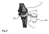
上述の図を参照すると、本発明による外科手術補助具は、関節の第1の骨と接触して配置するための第1の要素(10)を備える。膝プロテーゼの場合、第1の骨は、大腿骨(F)である。特に、第1の要素(10)は、大腿骨の下端部と接触して配置するためのものである。さらに、外科手術補助具は、関節の第2の骨と接触して配置するための第2の要素(20)を備える。膝インプラントの場合、第2の骨は、脛骨(T)である。特に、第2の要素(20)は、好ましくは、最小限の脛骨の切除手術に続いて、脛骨の上端部と接触して配置するためのものである。 Referring to the above figures, the surgical aid according to the present invention comprises a first element (10) for placement in contact with the first bone of the joint. In the case of a knee prosthesis, the first bone is the femur (F). In particular, the first element (10) is for placement in contact with the lower end of the femur. Furthermore, the surgical aid comprises a second element (20) for placement in contact with the second bone of the joint. In the case of a knee implant, the second bone is the tibia (T). In particular, the second element (20) is preferably for placement in contact with the upper end of the tibia following minimal tibial resection surgery.
第1および第2の要素(10,20)は、少なくとも第1の方向(X)に沿って互いに相対的に移動可能である。アクチュエータまたはモータ(50)は、第1の要素(10)および第2の要素(20)を互いに離間させようとする力を加えるように配置される。このようなアクチュエータまたはモータ(50)は、第1および第2の要素(10,20)の間に配置してもよい。図示の実施形態では、アクチュエータまたはモータ(50)は、第1および第2の要素(10,20)のうちの1つ、例えば第2の要素(10)に結合され、能動部(active portion)とともに第2の要素(20)に作用する。アクチュエータまたはモータ(50)は、例えば、油圧シリンダおよび/またはねじ機構または他のシステムを備え、2つの要素を互いに軸方向に離間させる。この場合、アクチュエータ本体またはモータ(50)は第2の要素(20)に結合され、ステム(stem)またはスピンドルナット(spindle nut)は第1の要素(10)に結合される。 The first and second elements (10, 20) are movable relative to each other at least along the first direction (X). The actuator or motor (50) is arranged to apply a force that attempts to separate the first element (10) and the second element (20) from each other. Such an actuator or motor (50) may be disposed between the first and second elements (10, 20). In the illustrated embodiment, the actuator or motor (50) is coupled to one of the first and second elements (10, 20), for example the second element (10), and an active portion. And acts on the second element (20). The actuator or motor (50) comprises, for example, a hydraulic cylinder and / or a screw mechanism or other system to separate the two elements axially from each other. In this case, the actuator body or motor (50) is coupled to the second element (20) and the stem or spindle nut is coupled to the first element (10).
外科手術補助具は、変位センサ(30)を備えており、該変位センサ(30)は、第1および第2の要素(10、20)間の相対的な変位を測定するように予め配置されている。特に、変位センサ(30)は、ゼロ点位置または当初の予め設定された位置に対して、第1および第2の要素(10、20)間の相対的な変位を測定する。ここで、予め設定された位置とは、第1および第2の要素(10、20)が既知の距離に配置された位置である。本質的には、この最初の既知の距離は、脛骨と大腿骨の間の間隔(space)を全可動域にわたって計算するための最初の基準として理解されるべきである。図1に示すように、変位センサは、アクチュエータまたはモータ(50)に結合することができる。その結果、アクチュエータまたはモータ(50)が実行するストロークを測定することにより、第1および第2の要素(10,20)の間の変位を検出することができる。外科手術補助具は、さらに、力センサ(51)を備える。該力センサ(51)は、概略のみ示され、アクチュエータまたはモータ(50)が及ぼす力を測定するために予め配置される。 The surgical aid includes a displacement sensor (30) that is pre-positioned to measure the relative displacement between the first and second elements (10, 20). ing. In particular, the displacement sensor (30) measures the relative displacement between the first and second elements (10, 20) relative to a zero point position or an initial preset position. Here, the preset position is a position where the first and second elements (10, 20) are arranged at a known distance. In essence, this first known distance is to be understood as an initial criterion for calculating the space between the tibia and the femur over the entire range of motion. As shown in FIG. 1, the displacement sensor can be coupled to an actuator or a motor (50). As a result, the displacement between the first and second elements (10, 20) can be detected by measuring the stroke performed by the actuator or motor (50). The surgical aid further comprises a force sensor (51). The force sensor (51) is shown only schematically and is pre-arranged to measure the force exerted by the actuator or motor (50).
好ましくは、外科手術補助具は、さらに、第1の要素(10)および/または第2の要素(20)に作用する圧力を検出するように構成された圧力センサ(40)を備える。例えば、圧力センサ(40)は、関節の第1の骨(F)と接触する領域において、第1の要素(10)と結合させてもよい。圧力センサ(40)は、圧力のピークの存在または圧力の不均一な分布を検出するのに有用であり、圧力のピークの存在または圧力の不均一な分布は、ともに関節の不正確な位置決めまたは立体構造を示す。したがって、このデータは、全可動域にわたって実行される位置決めを確認するために望ましい。 Preferably, the surgical aid further comprises a pressure sensor (40) configured to detect pressure acting on the first element (10) and / or the second element (20). For example, the pressure sensor (40) may be coupled to the first element (10) in the region of the joint that contacts the first bone (F). The pressure sensor (40) is useful for detecting the presence of a pressure peak or a non-uniform distribution of pressure, both of which may cause inaccurate positioning of the joint or The three-dimensional structure is shown. This data is therefore desirable to confirm the positioning performed over the entire range of motion.
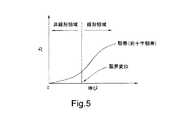
変位センサ(30)、力センサ(51)および圧力センサ(40)は、これらを備える場合には、アクチュエータまたはモータ(50)を制御するために予め配置された処理モジュール(60)に接続される。特に、処理モジュール(60)は、膝の関節可動域の全体にわたる、異なる角度位置または関節屈曲伸展(different angular positions or joint flexion-extension)において、変位センサ(30)が測定する変位を検出すると同時に、力/変位線図(force-displacement diagram)を展開することによって、アクチュエータ/モータ(50)が及ぼす力を次第に増加させる。 The displacement sensor (30), force sensor (51) and pressure sensor (40), if provided, are connected to a pre-arranged processing module (60) for controlling the actuator or motor (50). . In particular, the processing module (60) simultaneously detects the displacement measured by the displacement sensor (30) at different angular positions or joint flexion-extensions throughout the range of motion of the knee. The force exerted by the actuator / motor (50) is gradually increased by developing a force-displacement diagram.
軟組織の等尺性張力は、力センサ(51)、もし備える場合は圧力センサ(40)、および、関節の異なる角度位置または屈曲伸展位置における変位センサ(30)によって得られる、力−伸び線図(force-elongation diagram)の分析を通じて、処理モジュール(60)により検出される。任意の所定の角度位置において、力−変位線図が、等尺性状態の終了を示す正味の傾斜変化(net slope change)を示すと直ぐに、ディストラクション(distraction,伸延、牽引)は、実質的に終了する。関節について選択した、角度位置または屈曲伸展位置のそれぞれについて、処理モジュールは、上記の力/変位線図を描き、それにより、力/変位線図の傾斜の変化が生じる限界変位値(critical displacement value)を検出する。そのような限界変位は、選択した角度位置のそれぞれについて、大腿骨と脛骨との間の最大距離に実質的に対応し、ここで、関節包靭帯組織は等尺性状態にある。関節の角度位置または屈曲伸展位置の数は、力/変位線図の強さおよび展開の変動(variation of the strength and development of the force/displacement diagram)が実行されるように、随意に決定することができる。 The isometric tension of the soft tissue is obtained by a force sensor (51), a pressure sensor (40) if provided, and a displacement sensor (30) at different angular or flexion extended positions of the joint. It is detected by the processing module (60) through analysis of (force-elongation diagram). As soon as the force-displacement diagram shows a net slope change indicating the end of the isometric state at any given angular position, the distraction is substantially To finish. For each angular or flexion extension position selected for the joint, the processing module draws the above force / displacement diagram, thereby causing a critical displacement value that causes a change in the slope of the force / displacement diagram. ) Is detected. Such marginal displacement substantially corresponds to the maximum distance between the femur and tibia for each selected angular position, where the capsular ligament tissue is in an isometric state. The number of angular positions of the joints or flexion / extension positions should be determined arbitrarily so that a variation of the strength and development of the force / displacement diagram is performed. Can do.
選択した様々な角度位置のそれぞれにおいて、処理モジュール(60)は、力−変位線図の傾斜の変動が検出されるときまで、アクチュエータ/モータ(50)が及ぼす力の変動を制御する。そのとき、処理モジュール(60)は、第1および第2の要素(10,20)間の限界変位を検出する。このようにして、検出目的のために選択した角度位置のそれぞれについて、関節包靭帯組織が等尺性状態にある、間隔または最大脛骨大腿骨間距離(space or maximum tibiofemoral distance)が得られる。 At each of the various selected angular positions, the processing module (60) controls the variation in force exerted by the actuator / motor (50) until a variation in the slope of the force-displacement diagram is detected. At that time, the processing module (60) detects a critical displacement between the first and second elements (10, 20). In this way, for each angular position selected for detection purposes, a spacing or maximum tibiofemoral distance is obtained at which the capsular ligament tissue is in an isometric state.
膝の関節可動域にわたって、選択した異なる角度位置または屈曲伸展位置において、処理モジュール(60)は、変位センサ(30)が送信した変位信号を検出するように構成されており、該変位信号は、第1の方向(X)に沿った限界変位、すなわち、力−変位線図の傾きの変化に基づく変位値に対応する。各角度位置に対して記録された変位値は、蓄積され、その後、予め決定したアルゴリズムによって処理される。その結果、関節包靭帯組織が等尺性張力状態(conditions of isometric tension)を維持する最大脛骨大腿骨間距離に本質的に対応した、最適変位(optimal displacement)が得られる。この等尺性張力状態とは、すなわち、関節包靭帯組織が、力−変位曲線の傾きの変化が決定される際の張力よりも高い張力にさらされていないというという状態である。第1の方向(X)に沿って測定される、この最適変位は、基本的に、プロテーゼの理想的な高さ、または、少なくとも、実質的に平坦な関節面を示す、脛骨のプロテーゼ構成要素の理想的な高さに対応する。 The processing module (60) is configured to detect the displacement signal transmitted by the displacement sensor (30) at different angular positions or flexion extended positions selected over the range of motion of the knee, the displacement signal being This corresponds to the limit displacement along the first direction (X), that is, the displacement value based on the change in the slope of the force-displacement diagram. The displacement values recorded for each angular position are accumulated and then processed by a predetermined algorithm. The result is an optimal displacement that essentially corresponds to the maximum tibial femoral distance at which the joint capsule ligament tissue maintains the conditions of isometric tension. This isometric tension state means that the joint capsular ligament tissue has not been exposed to a tension higher than the tension at which the change in the slope of the force-displacement curve is determined. This optimal displacement, measured along the first direction (X), basically represents the ideal height of the prosthesis, or at least a substantially flat articular surface, the tibial prosthetic component Corresponds to the ideal height.
さらに、処理モジュール(60)が計算する大腿骨と脛骨の間の最適変位値に基づいて、大腿骨および/または脛骨の切除が実行されると、下肢の可動域にわたる、組織の等尺性を確認するために、外科手術補助具を用いることができる。その表面が永久的なプロテーゼ(permanent prosthesis)の幾何学的形状と整合した、試行の大腿骨構成要素(trial femoral component)を挿入した後、外科手術補助具を、脛骨の最終切除(final resection of the tibia)に挿入する。そして、可動域にわたって膝を動かすことによって、上記の力/変位測定が繰り返され、圧力センサ(40)により圧力を測定することができる。内側および/または外側の関節包靭帯組織の等尺性を全可動域にわたって獲得することを目的として、切断、インサートの厚さ、または構成要素のサイズは、検出された寸法の関数として修正してもよい。試行の大腿骨構成要素との接触表面において、外科手術補助具は、好ましくは、脛骨インサートの最終形状に等しい幾何学的形状を示す。 Further, when the femoral and / or tibia resection is performed based on the optimal displacement between the femur and the tibia calculated by the processing module (60), the isometric of the tissue over the range of motion of the lower limbs. To confirm, a surgical aid can be used. After inserting a trial femoral component whose surface is aligned with the permanent prosthesis geometry, the surgical aid is placed on the final resection of the tibia. the tibia). Then, by moving the knee over the range of motion, the above force / displacement measurement is repeated, and the pressure can be measured by the pressure sensor (40). In order to obtain isometricity of the medial and / or lateral joint capsule ligament tissue over the entire range of motion, the cutting, insert thickness, or component size can be modified as a function of the detected dimensions. Also good. At the contact surface with the trial femoral component, the surgical aid preferably exhibits a geometric shape equal to the final shape of the tibial insert.
内側または外側モノコンパートメントプロテーゼのインプラントのために、本発明による外科手術補助具は、以下に詳述するように使用することができる。大腿の重量が大腿骨と脛骨の間に働く力の検出に影響しないように、大腿骨に働くグリップを用いて、四肢をつりさげる。 For inner or outer monocompartmental prosthetic implants, the surgical aids according to the invention can be used as detailed below. The limbs are suspended using grips that act on the femur so that the weight of the thigh does not affect the detection of the force acting between the femur and the tibia.
大腿骨と脛骨の最終的な切除を行う前に、外科手術補助具を関節骨の端部の間に挿入し、第1および第2の要素(10,20)を骨自体の端部に接触して配置する。そのため、好ましくは、前額面および矢状面(frontal and sagittal planes)上の脛骨の機械的軸または解剖学的軸に沿って脛骨の予備的切除(preliminary resection)を行う。大腿骨はそのまま(骨切除なしで)保持する。 Prior to the final resection of the femur and tibia, a surgical aid is inserted between the ends of the joint bone and the first and second elements (10, 20) are in contact with the ends of the bone itself And place it. Therefore, a preliminary resection of the tibia is preferably performed along the mechanical or anatomical axis of the tibia on the frontal and sagittal planes. The femur is kept intact (without osteotomy).
関節は、完全な伸展から完全な屈曲まで、例えば、例えば0°(直線脚)と150°の間の範囲内で屈曲する。ある予め決定した数の角度位置において、処理モジュール(60)が処理した、力/変位曲線が、非線形傾向から線形傾向に変化する測定点(point)まで、アクチュエータ/モータ(50)が及ぼす力が変動し、第1および第2の要素(10,20)は、互いに対して動く。そこで、処理モジュール(60)自体が蓄積する、対応する限界変位値と同様に、等尺性関節包靭帯組織の張力値(tension value)が示される。測定が実行される角度位置のそれぞれにおいて、処理モジュール(60)は、力/変位曲線の傾向が、非線形傾向から線形傾向に変化する値において、等尺性の力の値(isometric force value)(または等尺性張力)も同様に蓄積する。 The joint bends from full extension to full bend, for example within a range between 0 ° (straight leg) and 150 °, for example. At a certain predetermined number of angular positions, the force exerted by the actuator / motor (50) is measured by the processing module (60) to a measurement point where the force / displacement curve changes from a non-linear trend to a linear trend. Fluctuating, the first and second elements (10, 20) move relative to each other. Thus, the tension value of the isometric joint bullous ligament tissue is shown as well as the corresponding limit displacement value stored by the processing module (60) itself. At each angular position at which the measurement is performed, the processing module (60) determines the isometric force value (at the value at which the force / displacement curve trend changes from a non-linear trend to a linear trend). Or isometric tension) accumulates as well.
検出が完了するか、または骨の間の関節回転が完了した後、既に述べたアルゴリズムに従って、処理モジュール(60)は、大腿骨と脛骨との間の最適変位値(または間隔)を決定する。計算された最適変位は、本質的にプロテーゼまたは少なくともプロテーゼの脛骨構成要素の全体の厚さに対応し、その正しい空間的な向きの実施が可能となる。これにより、関節包靭帯の内部および外部関節構造の等尺性に適合するプロテーゼ構成要素の関節運動学(joint kinematics)を得ることできる。 After detection or joint rotation between bones is completed, processing module (60) determines an optimal displacement value (or spacing) between the femur and tibia according to the algorithm already described. The calculated optimal displacement essentially corresponds to the overall thickness of the prosthesis or at least the tibial component of the prosthesis, allowing its correct spatial orientation to be performed. This provides joint kinematics of prosthetic components that match the isometric nature of the internal and external joint structures of the joint capsule ligament.
本発明による外科手術補助具は、さらに、関節の2つの骨の間で、傾斜角を計測するよう構成された角度測定装置(35)を備えていてもよく、該角度測定装置(35)は、処理モジュール(60)に接続される。そのような角度測定装置は、例えば、慣性センサの形態であってもよい。可能な実施形態では、角度測定装置は、大腿骨および脛骨にそれぞれ結合するよう配置された、1対の慣性センサ(図4に概略を示す)を備える。例えば、第1のセンサは、(バンドなどによって)大腿に取り付けることができ、第2のセンサは、脛骨または患者の足首に取り付けることができる。 The surgical aid according to the present invention may further comprise an angle measuring device (35) configured to measure an inclination angle between the two bones of the joint, the angle measuring device (35) being , Connected to the processing module (60). Such an angle measuring device may be in the form of an inertial sensor, for example. In a possible embodiment, the angle measurement device comprises a pair of inertial sensors (shown schematically in FIG. 4) arranged to couple to the femur and tibia, respectively. For example, the first sensor can be attached to the thigh (such as by a band) and the second sensor can be attached to the tibia or the patient's ankle.
処理モジュール(60)は、変位センサ(30)および角度測定装置(35)が発信する信号を検出するよう、また、第1の方向(X)に沿った変位の変動を、関節の2つの骨の間の傾斜角の関数でトレースするよう予め配置されている。言い換えれば、処理モジュール(60)は、角度/変位線図を描くように構成されている。 The processing module (60) detects the signals emitted by the displacement sensor (30) and the angle measuring device (35), and detects the variation of the displacement along the first direction (X), in the two bones of the joint. Is pre-arranged to trace with a function of the tilt angle between. In other words, the processing module (60) is configured to draw an angle / displacement diagram.
角度測定装置(35)は、プロテーゼまたは少なくともプロテーゼ脛骨構成要素の関節面を近似するか、あるいは取得するために、好都合に使用することができる。 The angle measuring device (35) can be advantageously used to approximate or obtain the prosthesis or at least the articular surface of the prosthetic tibial component.
第1の可能な使用方法では、前記の実施態様にしたがって、最適変位および等尺性張力値を決定した後、アクチュエータまたはモータ(50)が及ぼす力を、前記等尺性張力に対応した値に維持することが可能である。関節骨を2つの所定の角度位置の間で回転させることによって、第1および第2の要素(10,20)の間の変位が生成され、該変位は変位センサ(30)によって検出される。同時に、角度測定装置(35)によって、関節骨の間の角変位が検出される。処理モジュール(60)は、矢状面上の投影に見られる、脛骨プロテーゼの関節面の輪郭(profile)をかなり良く規定できる曲線を描くことによって、第1の方向(X)に沿った関節骨の間の変位を、関節骨の間の傾斜角と、相互に関連させることができる。このようにして得られ、図6に定性的にのみ示された相関角/変位曲線(correlation angle/displacement curve)は、既製のプロテーゼ(ready-to-use prosthesis)を最適に選択するために、または、カスタムメイドのプロテーゼを最初から(ex novo)形成するために使用することができる。 In a first possible method of use, after determining the optimum displacement and isometric tension value according to the above embodiment, the force exerted by the actuator or motor (50) is set to a value corresponding to the isometric tension. It is possible to maintain. By rotating the articular bone between two predetermined angular positions, a displacement between the first and second elements (10, 20) is generated, which is detected by a displacement sensor (30). At the same time, the angular displacement between the joint bones is detected by the angle measuring device (35). The processing module (60) draws a curve that can fairly well define the articular surface profile of the tibial prosthesis as seen in the projection on the sagittal plane, thereby providing the articular bone along the first direction (X). Can be correlated with the angle of inclination between the articular bones. The correlation angle / displacement curve obtained in this way and shown only qualitatively in FIG. 6 is used to optimally select a ready-to-use prosthesis. Alternatively, a custom-made prosthesis can be used to form ex novo.
第2の可能な使用方法では、関節骨の間の回転角度は、上記で説明した方法により、力−変位測定の実行を決定した、任意の角度位置で検出される。例えば、実質的に伸展した脚の状態(0°に近い角度)から開始し、150°の角度までの、所定の数の角度位置に対して、処理モジュール(60)は、既に説明したように、限界変位を検出し、該限界変位を、センサ(35)を介して検出した、対応する角度との相関関係に置く。このようにして、各角度に対して、各限界変位が関連づけられる。該限界変位は、既に述べたように、力/変位曲線の傾斜の変化が生じる変位に対応する。このように、矢状面に見られる脛骨プロテーゼの関節面の輪郭を近似する角度/変位の傾向が、図6に示されるように描写される。 In a second possible method of use, the rotation angle between the articular bones is detected at any angular position that has decided to perform a force-displacement measurement by the method described above. For example, for a predetermined number of angular positions starting from a substantially extended leg condition (an angle close to 0 °) and up to an angle of 150 °, the processing module (60) is as described above. , Detect the limit displacement, and place the limit displacement in correlation with the corresponding angle detected via the sensor (35). In this way, each critical displacement is associated with each angle. The limit displacement corresponds to the displacement that causes a change in the slope of the force / displacement curve, as already mentioned. Thus, the tendency of angle / displacement approximating the contour of the articular surface of the tibial prosthesis seen in the sagittal plane is depicted as shown in FIG.
本明細書で開示したすべての手順において、切除および試行の大腿骨構成要素のインサートに続いて、外科手術補助具は、脛骨の最終切除において、その位置を変えることができ、また、内側または外側コンパートメントの関節包靭帯組織の等尺性を試験することができる。これにより、骨切除における変更が可能となるか、または、関節包靭帯組織の張力を数量化し、変更することができる。 In all procedures disclosed herein, following the resection and insertion of the femoral component of the trial, the surgical aid can be repositioned in the final resection of the tibia and can be medial or lateral The isometricity of the joint capsular ligament tissue in the compartment can be tested. This allows changes in bone resection or can quantify and change the tension of the capsular ligament tissue.
大腿骨および脛骨に関して、骨切除の向きおよび範囲の決定が患者にとって正確であるためには、大腿骨および脛骨の幾何学的画像がCTまたはNMRを介して得られる、コンピュータ支援ナビゲーションおよび/またはロボットシステムによって、関連データが処理されなければならない。さらに、プロテーゼ構成要素の位置を、最適な靭帯張力の関数として最適化または変更することを目的として、CTまたはNMRを介した大腿骨および脛骨の構成要素の解剖学的位置決めのための、切断テンプレート(cutting templates)の実現に、外科手術補助具を用いることができる。 Computer-aided navigation and / or robots in which geometric images of the femur and tibia are obtained via CT or NMR in order for the femoral and tibia to be accurate for the patient to determine the direction and extent of bone resection The relevant data must be processed by the system. In addition, a cutting template for anatomical positioning of femoral and tibia components via CT or NMR with the aim of optimizing or changing the position of the prosthetic component as a function of optimal ligament tension Surgical aids can be used to realize (cutting templates).
同じ技術は、2つの装置、すなわち、1つの内側装置(medial device)と、1つの外側装置(lateral device)を用いることによって、1コンパートメントプロテーゼ(mono-compartmental prosthesis)、2コンパートメント十字靭帯保存完全プロテーゼ(bi-compartmental-Cruciate-Retaining full prosthesis)、後十字靭帯温存または後十字靭帯切除完全プロテーゼ(posterior-Cruciate-Retaining or replacing posterior-Cruciate full prosthesis)の実現に適用できる。本発明による外科手術補助具は、重要な利点を提供する。それは、関節包靭帯組織の等尺性を維持しながら、プロテーゼ要素の寸法設定と正確な位置決めを可能にすることである。加えて、本発明による外科手術補助具は、小型で非侵襲性である。さらに重要な利点は、関節骨の端部間に外科手術補助具を位置させるとともに、プロテーゼ構成要素の最適な位置決めと寸法設定を得るために、完全な関節運動を行うだけで十分であるから、外科手術補助具の使用によって処置時間が長くなることはないという事実によって与えられる。さらに、外科手術補助具は、構成要素の向き、および試行の構成要素とともに切除された骨の厚さの向きの試行および調整のための器具として使用してもよい。 The same technique uses a single device, a medial device and a lateral device, thereby providing a mono-compartmental prosthesis, a two-compartment cruciate ligament preservation complete prosthesis. (Bi-compartmental-Cruciate-Retaining full prosthesis), can be applied to the realization of posterior-cruciate-retaining or replacing posterior-Cruciate full prosthesis. The surgical aid according to the invention offers important advantages. It is to allow sizing and accurate positioning of the prosthetic element while maintaining the isometric nature of the joint capsule ligament tissue. In addition, the surgical aid according to the present invention is small and non-invasive. A further important advantage is that it is sufficient to perform a complete articulation in order to position the surgical aid between the ends of the articular bone and to obtain optimal positioning and sizing of the prosthetic components, Given by the fact that the use of surgical aids does not increase the treatment time. In addition, the surgical aid may be used as an instrument for trial and adjustment of component orientation and the thickness of the resected bone thickness with the trial component.
Claims (14)
Translated fromJapanese該外科手術補助具は、
関節の第1の骨と接触して配置するための第1の要素(10)と、
前記関節の第2の骨と接触して配置するための第2の要素(20)とを備え、
前記第1および第2の要素(10,20)は、少なくとも第1の方向(X)に沿って、互いに相対的に可動であり、
前記第1および第2の要素(10,20)の間の相対的な変位を測定するよう予め配置された変位センサ(30)と、
前記第1の要素および前記第2の要素を互いに離間させる力を及ぼすように予め設置されたアクチュエータ/モータ(50)と、
前記アクチュエータ/モータ(50)が及ぼす力を検出するのに適した力センサ(51)と、
前記変位センサ(30)および圧力センサ(40)が発信した信号を入力として受け取り、前記アクチュエータ/モータ(50)を制御するよう配置された処理モジュール(60)とを備えた
ことを特徴とする外科手術補助具。A surgical aid for joints,
The surgical aid is
A first element (10) for placement in contact with the first bone of the joint;
A second element (20) for placement in contact with the second bone of the joint;
The first and second elements (10, 20) are movable relative to each other at least along a first direction (X);
A displacement sensor (30) pre-positioned to measure a relative displacement between the first and second elements (10, 20);
An actuator / motor (50) pre-installed to exert a force to separate the first element and the second element from each other;
A force sensor (51) suitable for detecting the force exerted by the actuator / motor (50);
A surgical module comprising: a processing module (60) arranged to receive signals transmitted by the displacement sensor (30) and the pressure sensor (40) as inputs and to control the actuator / motor (50); Surgical aids.
前記処理モジュール(60)は、前記変位センサ(30)および前記力センサ(51)の信号を検出するよう、また、力/変位線図を処理するよう予め配置されており、
前記力/変位線図は、前記アクチュエータまたはモータ(50)が及ぼす力の値であって、前記力センサ(51)が検出した値から得られる力の値を、前記変位センサ(30)が検知した対応する変位値と関連付けるものである、外科手術補助具。The surgical aid according to claim 1,
The processing module (60) is pre-arranged to detect signals of the displacement sensor (30) and the force sensor (51) and to process a force / displacement diagram,
The force / displacement diagram is a force value exerted by the actuator or motor (50), and the displacement sensor (30) detects a force value obtained from a value detected by the force sensor (51). A surgical aid that is associated with the corresponding displacement value.
前記処理モジュール(60)は、少なくとも2つの屈曲位置において、線図が傾きの変化を示す変位を検出することによって、前記力/変位線図を蓄積するよう配置された、
外科手術補助具。The surgical aid according to claim 2, wherein
The processing module (60) is arranged to accumulate the force / displacement diagram by detecting a displacement in which the diagram shows a change in tilt at at least two bending positions;
Surgical aids.
前記処理モジュール(60)は、少なくとも2つの屈曲位置において、前記力/変位線図の上で該力/変位線図が非線形傾向から実質的に線形傾向に変わる前記変位を検出するよう配置された、外科手術補助具。A surgical aid according to claim 3, wherein
The processing module (60) is arranged to detect the displacement at which the force / displacement diagram changes from a non-linear trend to a substantially linear trend on the force / displacement diagram in at least two bending positions. Surgical aids.
前記処理モジュール(60)は、前記変位センサ(30)および前記力センサ(51)が発した信号を検出するように、また、この検出した信号に基づいて、関節骨の間の予め決定した角度位置において、前記力/変位線図を処理するように予め配置された、外科手術補助具。The surgical aid according to any one of claims 1 to 4,
The processing module (60) detects a signal generated by the displacement sensor (30) and the force sensor (51), and based on the detected signal, a predetermined angle between the joint bones. A surgical aid prepositioned to process the force / displacement diagram in position.
前記処理モジュール(60)は、最適変位を得るために、予め決定した角度位置において、前記力/変位線図の測定点を処理するためのアルゴリズムを備え、前記最適変位は、少なくとも1つのプロテーゼ構成要素の高さに対応して、第1の方向(X)に沿って測定される、外科手術補助具。A surgical aid according to claim 5, wherein
The processing module (60) comprises an algorithm for processing the measurement points of the force / displacement diagram at a predetermined angular position to obtain an optimal displacement, wherein the optimal displacement is at least one prosthesis configuration. Surgical aid measured along the first direction (X) corresponding to the height of the element.
前記第1の要素(10)および/または前記第2の要素(20)に作用する圧力を検出するよう予め配置された圧力センサ(40)を備えた、外科手術補助具。The surgical aid according to any one of claims 1 to 6,
Surgical aid comprising a pressure sensor (40) pre-positioned to detect pressure acting on the first element (10) and / or the second element (20).
前記関節の2つの骨の間の傾斜角を測定するよう配置された角度測定装置を備え、その傾斜角は、前記処理モジュール(60)に接続される、外科手術補助具。The surgical aid according to any one of claims 1 to 7,
Surgical aid comprising an angle measuring device arranged to measure an inclination angle between two bones of the joint, the inclination angle being connected to the processing module (60).
前記処理モジュール(60)は、
前記変位センサ(30)と前記角度測定装置の信号を検出し、前記関節の2つの骨の間の傾斜角の関数として、前記第1の方向(X)に沿って変位の変動をトレースするよう配置された、外科手術補助具。A surgical aid according to claim 8, wherein
The processing module (60)
Detecting the signals of the displacement sensor (30) and the angle measuring device and tracing the variation of the displacement along the first direction (X) as a function of the tilt angle between the two bones of the joint. Arranged surgical aids.
該方法は、
前記第1および第2の骨の間に、請求項1ないし9のいずれか1項に記載の外科手術補助具を挿入するステップであって、それによって、前記第1の骨の関節端部は前記第1の要素(10)と接触し、前記第2の骨の関節端部は前記第2の要素(20)と接触している、挿入するステップと、
予め決定した様々な関節角度位置のそれぞれにおいて、前記アクチュエータ/モータ(50)が及ぼす前記力を変化させるステップと、前記アクチュエータ/モータ(50)が及ぼす前記力の値を、前記変位センサ(30)が検出した対応する変位値と関連付ける、力−変位線図を展開することによって、前記変位センサ(30)が測定した前記変位を検出するステップと、
前記予め決定した様々な関節角度位置のそれぞれにおいて、前記力−変位線図が非線形傾向から実質的に線形傾向に変化するか、または、前記力/変位曲線における傾斜の第1の変化が起きる場合に、前記変位センサ(30)および力センサが測定した変位値を、検出し蓄積するステップと、
前記第1の方向(X)に沿って測定される最適変位が得られるように、予め決定したアルゴリズムに従って蓄積された変位値を処理するステップであって、該変位値において関節包靭帯構造の等尺性張力、すなわち、実質的に前記力/伸び曲線の傾斜の変化に対応した張力値を超えない張力が生成され、前記決定した変位は少なくとも1つのプロテーゼ構成要素の高さに対応する、処理するステップとを備えた方法。A method for determining a first and / or second bone resection for an implant of a joint prosthesis comprising:
The method
10. A step of inserting a surgical aid according to any one of claims 1 to 9 between the first and second bones, whereby the joint end of the first bone is Inserting, in contact with the first element (10), the articular end of the second bone being in contact with the second element (20);
A step of changing the force exerted by the actuator / motor (50) at each of various joint angle positions determined in advance, and a value of the force exerted by the actuator / motor (50) are represented by the displacement sensor (30). Detecting the displacement measured by the displacement sensor (30) by developing a force-displacement diagram associated with the corresponding displacement value detected by
The force-displacement diagram changes from a non-linear trend to a substantially linear trend or a first change in slope in the force / displacement curve occurs at each of the various predetermined joint angular positions. And detecting and accumulating displacement values measured by the displacement sensor (30) and the force sensor;
Processing the accumulated displacement value according to a predetermined algorithm so as to obtain an optimum displacement measured along the first direction (X), wherein the displacement value of the joint capsule ligament structure, etc. A process in which isometric tension, i.e. a tension that does not substantially exceed a tension value corresponding to a change in the slope of the force / elongation curve, is generated, the determined displacement corresponding to the height of at least one prosthesis component And a step comprising:
該方法は、前記最適変位および等尺性張力を決定した後に、
前記アクチュエータ/モータ(50)が及ぼす力を、前記関節包靭帯構造の前記等尺性張力に対応した値に維持するステップと、
2つの予め決定した角度位置の間において、関節骨を回転させるステップ、
前記関節の2つの骨の間の傾斜角の関数として、前記第1の方向(X)に沿って、変位の変動をトレースするステップとを備えた方法。The method of claim 10, comprising:
After determining the optimal displacement and isometric tension, the method includes:
Maintaining the force exerted by the actuator / motor (50) at a value corresponding to the isometric tension of the joint ligament structure;
Rotating the articulated bone between two predetermined angular positions;
Tracing the variation in displacement along the first direction (X) as a function of the angle of inclination between the two bones of the joint.
請求項10ないし12のいずれか1項記載の方法によって、前記第1および/または第2の骨の切除を決定するステップと、
前記第1および/または第2の骨の切除を実施するステップと、
プロテーゼ関節を埋め込むステップとを備えた方法。A method for implanting a joint prosthesis comprising:
Determining the resection of the first and / or second bone by the method according to any one of claims 10-12;
Performing a resection of said first and / or second bone;
Embedding a prosthetic joint.
前記関節の2つの骨の間の前記傾斜角の関数として、前記第1の方向(X)に沿って、前記変位の変動に従って構成された、関節面を示す、少なくとも1つのプロテーゼ構成要素を選択するか、または、該プロテーゼ構成要素を実現するステップと、
前記プロテーゼ構成要素を埋め込むステップとを備えた方法。The method according to claim 11 or 12, comprising:
Select at least one prosthetic component that exhibits an articulating surface configured according to the variation of the displacement along the first direction (X) as a function of the tilt angle between the two bones of the joint Or realizing the prosthetic component;
Embedding the prosthesis component.
プロテーゼ関節のインプラントの後に、
前記第1および第2の骨の間に、前記外科手術補助具を再挿入し、前記第1の骨と関連するプロテーゼ部分が前記第1の要素(10)と接触し、前記第2の骨と関連するプロテーゼ部分が前記第2の要素(20)と接触するステップと、
請求項10または11に記載のステップを実行し、それによって、切除を近似する測定点の新たな組を得るステップと、
新しい測定点の1組が、予めセットした閾値を超えて、以前の測定点の1組からはずれる場合には、プロテーゼを除去し、切除を近似する新しい測定点の1組と対応した、前記第1および/または第2の骨の新たな切除を行うステップとを備えた方法。14. A method according to claim 12 or 13, comprising
After the prosthetic joint implant,
The surgical aid is reinserted between the first and second bones, and the prosthetic portion associated with the first bone contacts the first element (10), and the second bone A prosthetic portion associated with said second element (20) in contact;
Performing the steps of claim 10 or 11 thereby obtaining a new set of measurement points approximating ablation;
If the new set of measurement points exceeds a preset threshold and deviates from the previous set of measurement points, the prosthesis is removed and the first set of measurement points corresponding to the new set of measurement points approximating ablation. Performing a new resection of the first and / or second bone.
Applications Claiming Priority (3)
| Application Number | Priority Date | Filing Date | Title |
|---|---|---|---|
| IT102015902339316 | 2015-03-19 | ||
| ITMO20150063 | 2015-03-19 | ||
| PCT/IB2016/051534WO2016147153A1 (en) | 2015-03-19 | 2016-03-18 | A surgical aid for joints |
Publications (2)
| Publication Number | Publication Date |
|---|---|
| JP2018509208Atrue JP2018509208A (en) | 2018-04-05 |
| JP2018509208A5 JP2018509208A5 (en) | 2018-05-24 |
Family
ID=53189944
Family Applications (1)
| Application Number | Title | Priority Date | Filing Date |
|---|---|---|---|
| JP2017545669APendingJP2018509208A (en) | 2015-03-19 | 2016-03-18 | Surgical aids for joints |
Country Status (4)
| Country | Link |
|---|---|
| US (1) | US10537444B2 (en) |
| EP (1) | EP3270832B1 (en) |
| JP (1) | JP2018509208A (en) |
| WO (1) | WO2016147153A1 (en) |
Cited By (2)
| Publication number | Priority date | Publication date | Assignee | Title |
|---|---|---|---|---|
| JP2023516614A (en)* | 2020-02-28 | 2023-04-20 | デピュイ・アイルランド・アンリミテッド・カンパニー | Soft tissue balancing in knee replacement |
| JP2024109769A (en)* | 2019-03-12 | 2024-08-14 | マコ サージカル コーポレーション | Systems and methods for robotically assisted soft tissue assessment |
Families Citing this family (20)
| Publication number | Priority date | Publication date | Assignee | Title |
|---|---|---|---|---|
| US7559931B2 (en) | 2003-06-09 | 2009-07-14 | OrthAlign, Inc. | Surgical orientation system and method |
| AU2009273863B2 (en) | 2008-07-24 | 2014-12-18 | OrthAlign, Inc. | Systems and methods for joint replacement |
| AU2009291743B2 (en) | 2008-09-10 | 2015-02-05 | Orthalign, Inc | Hip surgery systems and methods |
| US10869771B2 (en) | 2009-07-24 | 2020-12-22 | OrthAlign, Inc. | Systems and methods for joint replacement |
| US9649160B2 (en) | 2012-08-14 | 2017-05-16 | OrthAlign, Inc. | Hip replacement navigation system and method |
| US10363149B2 (en) | 2015-02-20 | 2019-07-30 | OrthAlign, Inc. | Hip replacement navigation system and method |
| CA2954125C (en)* | 2015-03-24 | 2018-09-04 | Omnilife Science, Inc. | Orthopedic joint distraction device |
| US11185425B2 (en) | 2016-12-22 | 2021-11-30 | Orthosensor Inc. | Surgical tensor configured to distribute loading through at least two pivot points |
| US11266512B2 (en) | 2016-12-22 | 2022-03-08 | Orthosensor Inc. | Surgical apparatus to support installation of a prosthetic component and method therefore |
| US10772641B2 (en) | 2016-12-22 | 2020-09-15 | Orthosensor Inc. | Surgical apparatus having a frame and moving support structure and method therefore |
| US11284873B2 (en) | 2016-12-22 | 2022-03-29 | Orthosensor Inc. | Surgical tensor where each distraction mechanism is supported and aligned by at least two guide shafts |
| US11291437B2 (en) | 2016-12-22 | 2022-04-05 | Orthosensor Inc. | Tilting surgical tensor to support at least one bone cut |
| CA3056495A1 (en)* | 2017-03-14 | 2018-09-20 | OrthAlign, Inc. | Soft tissue measurement & balancing systems and methods |
| US10864044B2 (en) | 2017-03-14 | 2020-12-15 | Smith & Nephew, Inc. | Systems and methods for measuring bone joint laxity |
| IT201900001987A1 (en) | 2019-02-12 | 2020-08-12 | Ncs Lab S R L | Improved Surgical Aid |
| US20210228377A1 (en) | 2020-01-29 | 2021-07-29 | Howmedica Osteonics Corp. | Load Sensor Balancer Instruments |
| WO2021158972A1 (en)* | 2020-02-07 | 2021-08-12 | New York Society For The Relief Of The Ruptured And Crippled, Maintaining The Hospital For Special Surgery | System and method for quantifying gap assessment examination |
| WO2021247990A1 (en)* | 2020-06-05 | 2021-12-09 | Smith & Nephew, Inc. | Automatic adjustment of tensioner device |
| CN114847887B (en)* | 2022-07-07 | 2022-12-13 | 北京壹点灵动科技有限公司 | Measuring device for knee joint soft tissue balance and control method thereof |
| CN119700383B (en)* | 2023-09-28 | 2025-09-02 | 北京天智航医疗科技股份有限公司 | Self-calibration method for measuring parameters of measuring device, electronic device and storage medium |
Citations (6)
| Publication number | Priority date | Publication date | Assignee | Title |
|---|---|---|---|---|
| JP2001517135A (en)* | 1998-01-20 | 2001-10-02 | サルザー オーソペディクス インコーポレーテッド | An instrument for determining the balance of the knee joint |
| US20060241569A1 (en)* | 2005-03-31 | 2006-10-26 | Disilvestro Mark R | Method and apparatus for use in balancing ligaments of a knee |
| JP2010005407A (en)* | 2008-06-27 | 2010-01-14 | Depuy Products Inc | Balancer for ligament of knee |
| US20100249665A1 (en)* | 2009-03-26 | 2010-09-30 | Martin Roche | System and method for orthopedic distraction and cutting block |
| JP2010240406A (en)* | 2009-03-31 | 2010-10-28 | Depuy Products Inc | Apparatus and method for displaying joint force data |
| US20120172762A1 (en)* | 2009-05-14 | 2012-07-05 | Blue Ortho | Device and method of automatic calibration of a tensor in arthroplasty procedures |
Family Cites Families (3)
| Publication number | Priority date | Publication date | Assignee | Title |
|---|---|---|---|---|
| FR2858547B1 (en)* | 2003-08-05 | 2005-11-04 | Depuy France | DEVICE FOR DYNAMICALLY POWERING A NATURAL OR PROTHETIC KNEE JOINT |
| EP2346446B1 (en)* | 2008-08-20 | 2017-06-07 | Synvasive Technology, Inc. | Sensing force during partial and total knee replacement surgery |
| US20140094715A1 (en)* | 2012-09-28 | 2014-04-03 | Orthosensor Inc. | Distractor for measuring load and position of load applied by the muscular-skeletal system and method therefor |
- 2016
- 2016-03-18JPJP2017545669Apatent/JP2018509208A/enactivePending
- 2016-03-18EPEP16719904.1Apatent/EP3270832B1/enactiveActive
- 2016-03-18USUS15/549,915patent/US10537444B2/ennot_activeExpired - Fee Related
- 2016-03-18WOPCT/IB2016/051534patent/WO2016147153A1/ennot_activeCeased
Patent Citations (6)
| Publication number | Priority date | Publication date | Assignee | Title |
|---|---|---|---|---|
| JP2001517135A (en)* | 1998-01-20 | 2001-10-02 | サルザー オーソペディクス インコーポレーテッド | An instrument for determining the balance of the knee joint |
| US20060241569A1 (en)* | 2005-03-31 | 2006-10-26 | Disilvestro Mark R | Method and apparatus for use in balancing ligaments of a knee |
| JP2010005407A (en)* | 2008-06-27 | 2010-01-14 | Depuy Products Inc | Balancer for ligament of knee |
| US20100249665A1 (en)* | 2009-03-26 | 2010-09-30 | Martin Roche | System and method for orthopedic distraction and cutting block |
| JP2010240406A (en)* | 2009-03-31 | 2010-10-28 | Depuy Products Inc | Apparatus and method for displaying joint force data |
| US20120172762A1 (en)* | 2009-05-14 | 2012-07-05 | Blue Ortho | Device and method of automatic calibration of a tensor in arthroplasty procedures |
Cited By (2)
| Publication number | Priority date | Publication date | Assignee | Title |
|---|---|---|---|---|
| JP2024109769A (en)* | 2019-03-12 | 2024-08-14 | マコ サージカル コーポレーション | Systems and methods for robotically assisted soft tissue assessment |
| JP2023516614A (en)* | 2020-02-28 | 2023-04-20 | デピュイ・アイルランド・アンリミテッド・カンパニー | Soft tissue balancing in knee replacement |
Also Published As
| Publication number | Publication date |
|---|---|
| US10537444B2 (en) | 2020-01-21 |
| WO2016147153A1 (en) | 2016-09-22 |
| US20180021151A1 (en) | 2018-01-25 |
| EP3270832B1 (en) | 2019-05-01 |
| EP3270832A1 (en) | 2018-01-24 |
Similar Documents
| Publication | Publication Date | Title |
|---|---|---|
| US10537444B2 (en) | Surgical aid for joints | |
| US11712350B2 (en) | Devices and methods to prevent joint instability following arthroplasty | |
| EP3383284B1 (en) | Alignment device | |
| US9101393B2 (en) | Systems and methods for determining the mechanical axis of a femur | |
| CA2607036C (en) | Leg alignment for surgical parameter measurement in hip replacement surgery | |
| US20070066917A1 (en) | Method for simulating prosthetic implant selection and placement | |
| US20090125117A1 (en) | Leg alignment and length measurement in hip replacement surgery | |
| US20120172762A1 (en) | Device and method of automatic calibration of a tensor in arthroplasty procedures | |
| JPH08508652A (en) | Method and apparatus for simplifying total hip arthroplasty | |
| EP2103271A1 (en) | Joint implant placement | |
| AU2004266089B2 (en) | Device for dynamic tensioning of a natural or prosthetic knee joint | |
| CN115209825A (en) | Soft tissue balancing in knee replacement | |
| WO2021008892A1 (en) | Method for designing a joint prosthesis | |
| US20230066435A1 (en) | Orthopedic surgery system for soft tissue balancing and implant planning | |
| WO2010125474A2 (en) | Device and method of determination of the knee flexion axis in computer assisted surgery | |
| US12408999B2 (en) | Patient specific robotic bone implant positioning | |
| WO2020165787A1 (en) | Improved surgical aid |
Legal Events
| Date | Code | Title | Description |
|---|---|---|---|
| A521 | Request for written amendment filed | Free format text:JAPANESE INTERMEDIATE CODE: A523 Effective date:20180405 | |
| A621 | Written request for application examination | Free format text:JAPANESE INTERMEDIATE CODE: A621 Effective date:20180405 | |
| A131 | Notification of reasons for refusal | Free format text:JAPANESE INTERMEDIATE CODE: A131 Effective date:20190319 | |
| A02 | Decision of refusal | Free format text:JAPANESE INTERMEDIATE CODE: A02 Effective date:20191015 |