JP2018503549A - Rearview mirror system with display device - Google Patents
Rearview mirror system with display deviceDownload PDFInfo
- Publication number
- JP2018503549A JP2018503549AJP2017526092AJP2017526092AJP2018503549AJP 2018503549 AJP2018503549 AJP 2018503549AJP 2017526092 AJP2017526092 AJP 2017526092AJP 2017526092 AJP2017526092 AJP 2017526092AJP 2018503549 AJP2018503549 AJP 2018503549A
- Authority
- JP
- Japan
- Prior art keywords
- light source
- display element
- display
- partially
- optical
- Prior art date
- Legal status (The legal status is an assumption and is not a legal conclusion. Google has not performed a legal analysis and makes no representation as to the accuracy of the status listed.)
- Granted
Links
Images


Classifications
- B—PERFORMING OPERATIONS; TRANSPORTING
- B60—VEHICLES IN GENERAL
- B60R—VEHICLES, VEHICLE FITTINGS, OR VEHICLE PARTS, NOT OTHERWISE PROVIDED FOR
- B60R1/00—Optical viewing arrangements; Real-time viewing arrangements for drivers or passengers using optical image capturing systems, e.g. cameras or video systems specially adapted for use in or on vehicles
- B60R1/12—Mirror assemblies combined with other articles, e.g. clocks
- B60R1/1207—Mirror assemblies combined with other articles, e.g. clocks with lamps; with turn indicators
- B—PERFORMING OPERATIONS; TRANSPORTING
- B60—VEHICLES IN GENERAL
- B60R—VEHICLES, VEHICLE FITTINGS, OR VEHICLE PARTS, NOT OTHERWISE PROVIDED FOR
- B60R1/00—Optical viewing arrangements; Real-time viewing arrangements for drivers or passengers using optical image capturing systems, e.g. cameras or video systems specially adapted for use in or on vehicles
- B60R1/02—Rear-view mirror arrangements
- B60R1/08—Rear-view mirror arrangements involving special optical features, e.g. avoiding blind spots, e.g. convex mirrors; Side-by-side associations of rear-view and other mirrors
- B60R1/083—Anti-glare mirrors, e.g. "day-night" mirrors
- B60R1/088—Anti-glare mirrors, e.g. "day-night" mirrors using a cell of electrically changeable optical characteristic, e.g. liquid-crystal or electrochromic mirrors
- F—MECHANICAL ENGINEERING; LIGHTING; HEATING; WEAPONS; BLASTING
- F21—LIGHTING
- F21V—FUNCTIONAL FEATURES OR DETAILS OF LIGHTING DEVICES OR SYSTEMS THEREOF; STRUCTURAL COMBINATIONS OF LIGHTING DEVICES WITH OTHER ARTICLES, NOT OTHERWISE PROVIDED FOR
- F21V19/00—Fastening of light sources or lamp holders
- F21V19/001—Fastening of light sources or lamp holders the light sources being semiconductors devices, e.g. LEDs
- F21V19/0015—Fastening arrangements intended to retain light sources
- G—PHYSICS
- G02—OPTICS
- G02B—OPTICAL ELEMENTS, SYSTEMS OR APPARATUS
- G02B27/00—Optical systems or apparatus not provided for by any of the groups G02B1/00 - G02B26/00, G02B30/00
- G02B27/10—Beam splitting or combining systems
- G02B27/14—Beam splitting or combining systems operating by reflection only
- G02B27/144—Beam splitting or combining systems operating by reflection only using partially transparent surfaces without spectral selectivity
- G—PHYSICS
- G02—OPTICS
- G02F—OPTICAL DEVICES OR ARRANGEMENTS FOR THE CONTROL OF LIGHT BY MODIFICATION OF THE OPTICAL PROPERTIES OF THE MEDIA OF THE ELEMENTS INVOLVED THEREIN; NON-LINEAR OPTICS; FREQUENCY-CHANGING OF LIGHT; OPTICAL LOGIC ELEMENTS; OPTICAL ANALOGUE/DIGITAL CONVERTERS
- G02F1/00—Devices or arrangements for the control of the intensity, colour, phase, polarisation or direction of light arriving from an independent light source, e.g. switching, gating or modulating; Non-linear optics
- G02F1/01—Devices or arrangements for the control of the intensity, colour, phase, polarisation or direction of light arriving from an independent light source, e.g. switching, gating or modulating; Non-linear optics for the control of the intensity, phase, polarisation or colour
- G02F1/15—Devices or arrangements for the control of the intensity, colour, phase, polarisation or direction of light arriving from an independent light source, e.g. switching, gating or modulating; Non-linear optics for the control of the intensity, phase, polarisation or colour based on an electrochromic effect
- G02F1/153—Constructional details
- G02F1/157—Structural association of cells with optical devices, e.g. reflectors or illuminating devices
- B—PERFORMING OPERATIONS; TRANSPORTING
- B60—VEHICLES IN GENERAL
- B60R—VEHICLES, VEHICLE FITTINGS, OR VEHICLE PARTS, NOT OTHERWISE PROVIDED FOR
- B60R1/00—Optical viewing arrangements; Real-time viewing arrangements for drivers or passengers using optical image capturing systems, e.g. cameras or video systems specially adapted for use in or on vehicles
- B60R1/12—Mirror assemblies combined with other articles, e.g. clocks
- B60R2001/1215—Mirror assemblies combined with other articles, e.g. clocks with information displays
- G—PHYSICS
- G02—OPTICS
- G02B—OPTICAL ELEMENTS, SYSTEMS OR APPARATUS
- G02B6/00—Light guides; Structural details of arrangements comprising light guides and other optical elements, e.g. couplings
- G02B6/0001—Light guides; Structural details of arrangements comprising light guides and other optical elements, e.g. couplings specially adapted for lighting devices or systems
- G02B6/0011—Light guides; Structural details of arrangements comprising light guides and other optical elements, e.g. couplings specially adapted for lighting devices or systems the light guides being planar or of plate-like form
- G02B6/0081—Mechanical or electrical aspects of the light guide and light source in the lighting device peculiar to the adaptation to planar light guides, e.g. concerning packaging
- G02B6/0083—Details of electrical connections of light sources to drivers, circuit boards, or the like
- G—PHYSICS
- G02—OPTICS
- G02B—OPTICAL ELEMENTS, SYSTEMS OR APPARATUS
- G02B6/00—Light guides; Structural details of arrangements comprising light guides and other optical elements, e.g. couplings
- G02B6/0001—Light guides; Structural details of arrangements comprising light guides and other optical elements, e.g. couplings specially adapted for lighting devices or systems
- G02B6/0011—Light guides; Structural details of arrangements comprising light guides and other optical elements, e.g. couplings specially adapted for lighting devices or systems the light guides being planar or of plate-like form
- G02B6/0081—Mechanical or electrical aspects of the light guide and light source in the lighting device peculiar to the adaptation to planar light guides, e.g. concerning packaging
- G02B6/0086—Positioning aspects
- G02B6/0088—Positioning aspects of the light guide or other optical sheets in the package
- G—PHYSICS
- G02—OPTICS
- G02B—OPTICAL ELEMENTS, SYSTEMS OR APPARATUS
- G02B6/00—Light guides; Structural details of arrangements comprising light guides and other optical elements, e.g. couplings
- G02B6/0001—Light guides; Structural details of arrangements comprising light guides and other optical elements, e.g. couplings specially adapted for lighting devices or systems
- G02B6/0011—Light guides; Structural details of arrangements comprising light guides and other optical elements, e.g. couplings specially adapted for lighting devices or systems the light guides being planar or of plate-like form
- G02B6/0081—Mechanical or electrical aspects of the light guide and light source in the lighting device peculiar to the adaptation to planar light guides, e.g. concerning packaging
- G02B6/0095—Light guides as housings, housing portions, shelves, doors, tiles, windows, or the like
- G—PHYSICS
- G02—OPTICS
- G02F—OPTICAL DEVICES OR ARRANGEMENTS FOR THE CONTROL OF LIGHT BY MODIFICATION OF THE OPTICAL PROPERTIES OF THE MEDIA OF THE ELEMENTS INVOLVED THEREIN; NON-LINEAR OPTICS; FREQUENCY-CHANGING OF LIGHT; OPTICAL LOGIC ELEMENTS; OPTICAL ANALOGUE/DIGITAL CONVERTERS
- G02F1/00—Devices or arrangements for the control of the intensity, colour, phase, polarisation or direction of light arriving from an independent light source, e.g. switching, gating or modulating; Non-linear optics
- G02F1/01—Devices or arrangements for the control of the intensity, colour, phase, polarisation or direction of light arriving from an independent light source, e.g. switching, gating or modulating; Non-linear optics for the control of the intensity, phase, polarisation or colour
- G02F1/15—Devices or arrangements for the control of the intensity, colour, phase, polarisation or direction of light arriving from an independent light source, e.g. switching, gating or modulating; Non-linear optics for the control of the intensity, phase, polarisation or colour based on an electrochromic effect
- G—PHYSICS
- G02—OPTICS
- G02F—OPTICAL DEVICES OR ARRANGEMENTS FOR THE CONTROL OF LIGHT BY MODIFICATION OF THE OPTICAL PROPERTIES OF THE MEDIA OF THE ELEMENTS INVOLVED THEREIN; NON-LINEAR OPTICS; FREQUENCY-CHANGING OF LIGHT; OPTICAL LOGIC ELEMENTS; OPTICAL ANALOGUE/DIGITAL CONVERTERS
- G02F2201/00—Constructional arrangements not provided for in groups G02F1/00 - G02F7/00
- G02F2201/44—Arrangements combining different electro-active layers, e.g. electrochromic, liquid crystal or electroluminescent layers
Landscapes
- Engineering & Computer Science (AREA)
- Physics & Mathematics (AREA)
- Multimedia (AREA)
- Mechanical Engineering (AREA)
- Optics & Photonics (AREA)
- General Physics & Mathematics (AREA)
- Crystallography & Structural Chemistry (AREA)
- Spectroscopy & Molecular Physics (AREA)
- Chemical & Material Sciences (AREA)
- Nonlinear Science (AREA)
- General Engineering & Computer Science (AREA)
- Devices For Indicating Variable Information By Combining Individual Elements (AREA)
- Liquid Crystal (AREA)
- Electrochromic Elements, Electrophoresis, Or Variable Reflection Or Absorption Elements (AREA)
- Planar Illumination Modules (AREA)
- Electroluminescent Light Sources (AREA)
Abstract
Translated fromJapaneseDescription
Translated fromJapanese本発明は、概して、後方視野デバイスシステムに関し、より詳細には、表示装置付き後方視野システムに関する。 The present invention relates generally to a rear vision device system, and more particularly to a rear vision system with a display.
本発明の少なくとも1つの態様は、部分的に反射性で部分的に透過性の要素と、部分的に反射性で部分的に透過性の要素と光通信する表示モジュールと、を有する後方視野デバイスシステムを含み、該表示モジュールは、表示装置、当該表示装置と光通信する光学ブロック、当該光学ブロックを通って伝播する照明を放射し、前記表示要素をエッジライトで照らすように構成された少なくとも1つの光源を含む第1の回路基板、前記光学ブロックと動作可能に接続され、少なくとも1つの開口部を画定する光学ホルダ、前記少なくとも1つの開口部および前記光学ブロックを通って伝播する照明を放射して、前記表示装置の一部およびアイコンのうちの少なくとも1つをバックライトで照らすように構成された少なくとも1つの光源を含む第2の回路基板、を有し、第1の回路基板の光源および第2の回路基板の光源によって放射された光は、前記部分的に反射性で部分的に透過性の要素を通して視認可能である。 At least one aspect of the present invention is a rear viewing device having a partially reflective and partially transmissive element and a display module in optical communication with the partially reflective and partially transmissive element. Including a system, wherein the display module is configured to emit a display device, an optical block in optical communication with the display device, illumination that propagates through the optical block, and illuminate the display element with an edge light. A first circuit board including one light source, an optical holder operably connected to the optical block and defining at least one opening, emitting illumination propagating through the at least one opening and the optical block. And at least one light source configured to illuminate at least one of the display device and at least one of the icons with a backlight. A circuit board, the light emitted by the first circuit board of the light source and the second circuit board of the light source is visible through the partially transmissive elements by the partially reflective.
本発明の少なくとも1つの態様は、部分的に反射性で部分的に透過性の要素と、部分的に反射性で部分的に透過性の要素と光通信する表示モジュールと、を有する後方視野デバイスシステムを含み、該表示モジュールは、部分的に反射性で部分的に透過性の要素を通って視認可能であるように構成されたアイコン、表示要素、当該表示要素と光通信する光学ブロック、当該光学ブロックと動作可能に接続された光学ホルダ、前記光学ブロックを通って伝播する照明を放射し、前記表示要素をエッジライトで照らすように構成されたエッジライト型プリント回路基板、前記光学ホルダ、前記光学ブロックおよび前記表示要素を通って光を伝播するように構成された前記プリント回路基板に電気的に接続された少なくとも1つの光源を有するプリント回路基板、を有し、プリント回路基板に電気的に接続された前記少なくとも1つの光源によって放射される光は、前記アイコンを照明し、前記部分的に反射性で部分的に透過性の要素を通して視認可能である。 At least one aspect of the present invention is a rear viewing device having a partially reflective and partially transmissive element and a display module in optical communication with the partially reflective and partially transmissive element. The display module includes an icon configured to be visible through a partially reflective and partially transmissive element, a display element, an optical block in optical communication with the display element, An optical holder operably connected to an optical block; an edge-light type printed circuit board configured to emit illumination propagating through the optical block and illuminate the display element with an edge light; the optical holder; A pre-comprising at least one light source electrically connected to the printed circuit board configured to propagate light through an optical block and the display element Light emitted by the at least one light source electrically connected to the printed circuit board illuminates the icon and the partially reflective and partially transmissive element Is visible through.
本発明の、これらおよび他の特徴、利点、および目的は、以下の明細書、特許請求の範囲、および添付図面を参照して、当業者によってさらに理解および認識されることになる。 These and other features, advantages, and objects of the present invention will be further understood and appreciated by those skilled in the art with reference to the following specification, claims, and appended drawings.
図示されたこの実施形態は、後方視野デバイスシステム、より詳細には、表示装置付きバックミラーシステムに関する、方法ステップおよび装置構成要素の組合せに主に属する。したがって、装置構成要素および方法ステップは、該当する場合、詳細によって開示を不明瞭にしないように、本発明の実施形態を理解することに関するそれらの特定の詳細のみを示す図面において、従来の符号によって表されている。前記詳細は、本明細書の説明の恩恵を有する当業者に容易に明らかになる。さらに、説明および図面における同類の数字は、同類の要素を表す。 This illustrated embodiment mainly belongs to a combination of method steps and apparatus components for a rear view device system, and more particularly for a rearview mirror system with a display. Accordingly, apparatus components and method steps, where applicable, are designated by conventional reference numerals in the drawings illustrating only those specific details relating to understanding embodiments of the invention so as not to obscure the disclosure with the details. It is represented. Such details will be readily apparent to one of ordinary skill in the art having the benefit of the description herein. Moreover, like numerals in the description and drawings represent like elements.
本明細書における記述の目的のために、用語「上部の」、「下部の」、「右の」、「左の」、「後方の」、「前方の」、「垂直の」、「水平の」、およびそれについての派生語は、図1において関連付けられた発明に関するものとする。別様に述べられない限り、用語「前方の」は、表示ミラーを見ることを意図される者により近い要素の表面を指すものであり、用語「後方の」は後方視野デバイスシステムを見ることを意図された者から離れた要素の表面を指すものである。しかしながら、それとは逆に明確に特定されたもの以外は、発明はさまざまな代わりの配向をとってもよい、と理解されるべきである。添付図面に図示され、かつ以下の明細書に記述された特定のデバイスおよびプロセスは、添付された特許請求の範囲において定義された発明概念の単なる例示的な実施形態であることも理解されるべきである。したがって、本明細書に開示された実施形態に関する特定の寸法および他の物理的特性は、特許請求の範囲が明示的に別段に述べない限り、限定するものと見なされるべきではない。 For the purposes of the description herein, the terms “upper”, “lower”, “right”, “left”, “backward”, “forward”, “vertical”, “horizontal” ”And its derivatives are related to the related invention in FIG. 1. Unless stated otherwise, the term “front” refers to the surface of the element that is closer to the person intended to view the display mirror, and the term “rear” refers to viewing the rear-view device system. It refers to the surface of the element away from the intended person. However, it should be understood that the invention may take a variety of alternative orientations, except where explicitly specified to the contrary. It is also to be understood that the specific devices and processes illustrated in the accompanying drawings and described in the following specification are merely exemplary embodiments of the inventive concepts defined in the appended claims. It is. Therefore, specific dimensions and other physical characteristics related to the embodiments disclosed herein are not to be considered limiting unless the claims are explicitly stated otherwise.
用語「including(含む)」、「comprises(備える)」、「comprising(備える)」、または任意の他の変形は、要素のリストを備えるプロセス、方法、物品、または装置が、それらの要素のみを含むのではなく、このようなプロセス、方法、物品、または装置に明示的に列挙されもせず、固有でもない他の要素を含んでもよいように、非排他的包括にわたるように意図される。「comprises a...」によって始められる要素は、さらなる制約を受けずに、その要素を備えるプロセス、方法、物品、または装置において、追加の同一要素の存在を妨げない。 The terms “including”, “comprises”, “comprising”, or any other variation, include a list of elements, a process, method, article, or device that includes only those elements. Rather than being included, such processes, methods, articles, or devices are not expressly listed and are intended to cover non-exclusive inclusions that may include other elements that are not unique. An element initiated by “comprises a ...” does not impede the presence of additional identical elements in a process, method, article, or apparatus comprising the element without further restrictions.
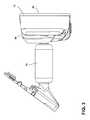
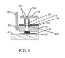
図1〜図3を参照すると、参照番号10は、後方視野デバイスシステムまたは車両用アセンブリを概して指定する。後方視野デバイスシステム10は、電気光学要素(本明細書において「ガラス要素」とも呼ばれる)などの部分的に反射性で部分的に透過性の要素12、および、当該部分的に反射性で部分的に透過性の要素12を通って見られる表示モジュール、を含む。後方視野デバイスシステム10は、部分的に反射性で部分的に透過性の要素12と表示モジュールとを保護し支持する前側シールド14および後側シールド16を更に含む。図4に示されるように、表示モジュールは、表示要素22、光学ブロック24、吸熱器26、および、一次プリント回路基板28を含む、いくつかの構成要素を概して含む。ハウジング30は、前側シールド14、表示モジュールおよび後側シールド16を少なくとも部分的に収容し、そこから後方に延在する取り付け部材32を含む。取り付け部材32は、車両のフロントガラスに取り付けるために適合化される。表示モジュールは、部分的に反射性で部分的に透過性の要素12の形状に対応する形状を有する。表示要素22は、液晶表示装置(LCD)、発光ダイオード(LED)、有機発光ダイオード(OLED)、プラズマ、またはデジタル光処理(DLP)表示要素であってもよい。 1-3,
図1〜図3を全体的に参照すると、後方視野デバイスシステム10は、ガラス要素12の前面42を含む、視域40を有する。視域40は、四角形形状、台形形状、または審美的理由のために望まれた任意の特別注文の輪郭形状であってもよい。 Referring generally to FIGS. 1-3, the posterior
ガラス要素12は、外部周囲46および当該外部周囲46の周りの縁48を有して、ほぼ平面状である。縁48は、制限することなく、シール、アップリケ、発泡接着剤、またはパッド印刷を含む、後方視野デバイスシステム10においてガラス要素12の後方に位置する1つまたは複数の要素を隠すように、クロム輪または他の同様の仕上げ材を組み込んでもよい。縁48は、ガラス要素12の外部周囲46から表示要素22の外端まで延在してもよい。あるいは、縁48は、より狭くて、縁48の少なくともいくつかの部分に沿って、外部周囲46から表示要素22の外端まで達しなくてもよい。ガラス要素12の周囲は、接地端、ベゼル端を有してもよく、またはフレームレスであってもよい。ハウジング30はまた、部分的に反射性で部分的に透過性の要素12の外部周囲46から盛り上がっていてもよい。 The
ガラス要素12は、電気光学要素またはプリズムなどの要素であってもよい。電気光学要素の1つの非限定的な例は、少なくとも1つの溶媒、少なくとも1つの陽極材料、および、少なくとも1つの陰極材料を含む、電気着色媒体である。典型的に、陽極材料および陰極材料の両方とも電気活性的であり、そのうちの少なくとも1つは電気着色的である。その通常の意味にかかわらず、用語「電気活性的」は、特定の電位差にさらされてその酸化状態に変質を受ける材料として、本明細書に定義されることが理解されるだろう。さらに、用語「電気着色的」は、その通常の意味にかかわらず、特定の電位差にさらされて1つまたは複数の波長でのその消衰係数において変化を示す材料として、本明細書において定義されることが理解されるであろう。電気着色的構成要素は、本明細書に記述されるように、電流が材料に印加される場合に、色または不透明度が第1の段階から第2の段階に変化するように、その色または不透明度が電流によって影響を受ける材料を含む。電気着色的構成要素は、参照によりそれらの全体が本明細書に組み込まれている、「Electrochromic Layer And Devices Comprising Same」と題された米国特許第5,928,572号、「Electrochromic Compounds」と題された米国特許第5,998,617号、「Electrochromic Medium Capable Of Producing A Pre−selected Color」と題された米国特許第6,020,987号、「Electrochromic Compounds」と題された米国特許第6,037,471号、「Electrochromic Media For Producing A Pre−selected Color」と題された米国特許第6、141、137号、「Electrochromic System」と題された米国特許第6、241、916号、「Near Infrared−Absorbing Electrochromic Compounds And Devices Comprising Same」と題された米国特許第6、193、912号、「Coupled Electrochromic Compounds With Photostable Dication Oxidation States」と題された米国特許第6、249、369号、「Electrochromic Media With Concentration Enhanced Stability,Process For The Preparation Thereof and Use In Electrochromic Devices」と題された米国特許第6,137,620号、「Electrochromic Device」と題された米国特許第6,519,072号、「Electrochromic Polymeric Solid Films,Manufacturing Electrochromic Devices Using Such Solid Films,And Processes For Making Such Solid Films And Devices」と題された国際特許出願第PCT/US98/05570号、「Electrochromic Polymer System」と題された国際特許出願第PCT/EP98/03862号、「Electrochromic Polymeric Solid Films,Manufacturing Electrochromic Devices Using Such Solid Films,And Processes For Making Such Solid Films And Devices」と題された国際特許出願第PCT/US98/05570号、において記述されたように、単層で単相の構成要素、多層の構成要素、または多相の構成要素であってもよい。ガラス要素12は、部分的に反射性で部分的に透過性の特性を有する他の任意の要素であってもよい。電流をガラス要素12に供給するために、それらの間に電位を生成するように、電気要素が要素の反対側に供給される。Jクリップは、それぞれの電気要素と電気的に係合され、素線がJクリップから一次プリント回路基板28に延在する。 The
以下の記述に関して、後方視野デバイスシステム10は、ガラス要素12の平面に垂直な直線が見る者の目の方に向かって延在する場合に、「軸上」と見なされる。ガラス要素12を通して見られる表示要素22が原因で、ガラス要素12上の眩輝が表示要素22の視認性に干渉することがある。後方視野デバイスシステム10が軸上にあり、夜間運転状態の間に使用される場合には、トレーリング車両(すなわち、後方視野デバイスシステム10を備えた車両の後ろを走行する車両)からのヘッドライトは、運転者に見える眩輝を引き起こし得る。本発明の一実施形態により、図2に示されるように、動作デバイス176は、後方視野デバイスシステム10と動作可能に結合される。作動デバイス176は、図示されたように、ボタンを含んでもよく、または「軸上」位置と「軸外」位置との間で表示装置を動かすように構成された、フリッパまたは他の作動部材を含んでもよいことが理解されるだろう。作動されると、作動デバイス176は、少なくともガラス要素12を軸外に動かす(すなわち、運転者の目の方に向かう直線から離れる)。典型的には、作動デバイス176の発動は、ガラス要素12を上方へ傾斜させ、ミラーを軸外位置に動かす。しかしながら、作動デバイス176は軸に対していかなる方向にもミラーを動かすように構成され得ることを、認識されるべきである。作動デバイス176は、起動されると、表示要素22を動かすようにも構成され得る。作動デバイス176は、表示要素22のスイッチの入切をするようにも構成され得る。したがって、作動デバイス176がミラーを軸外に動かすように作動される場合、表示要素22はスイッチを切られ得る、つまり停止され得る。 For the following description, the rear
さらに、後方視野デバイスシステム10を見る者に情報を提供するために、後方視野デバイスシステム10は、後方視野デバイスシステム10が使用中の場合、視域40で視認可能な表示要素22上の部分的に透過性のグラフィックオーバレイまたは画像などの、視界178に関する情報を含んでもよい。 Further, in order to provide information to the viewer of the rear
図4に示されるように、後方視野デバイスシステム10は、プリント回路基板120に電気的に接続され、かつ、光学ブロック24を通って表示要素22に光を伝播させるように構成された、少なくとも1つの光源203(例えば、LED)を備えるように構成される。アイコン202が、表示要素22上で視認可能で、部分的に反射性で部分的に透過性の要素12を通して見ることができる。少なくとも1つの光源200が、主プリント回路基板28に電気的に接続され、光学ホルダ201において画定された開口部を通って伝播する照明を放射するように構成される。光学ホルダ201は、光パイプ205を固定する。光は、部分的に反射性で部分的に透過性の要素12を通して見ることができる。図示されたように、光学ホルダ201は、光学ブロック24の裏面に沿って延在する係合壁212を有する保持部材210を含む。保持部材210は、光学ブロック24および主プリント回路基板28にほぼ直交して延在する保持壁214も含む。保持壁214は、光パイプ205の少なくとも一部と係合する。図示されたように、光パイプ205は、光源200に隣接する近接部を含む。光パイプ205は、フレアが反射性フィルム204を外側に通過した遠位部も含む。 As shown in FIG. 4, the back-
再び図4を参照すると、少なくとも1つの光源200によって放射された光が光ホルダ201を通って伝播すると、当該光は光学ブロック24を通って導かれる。反射性フィルム204は、光学ホルダ201と光学ブロック24との間の反射性材料のない領域を画定し、少なくとも1つの光源200によって放射された光が、光学ホルダ201の光パイプ205を通って光学ブロック24の中に伝播することができるようになる。少なくとも1つの光源200によって放射された光は、光学ブロック24を通って伝播すると、その後、その光は表示要素22を通って方向付けられる。少なくとも1つの光源200によって放射された光は、その後、アイコン202によって部分的に遮断されるかフィルタ処理され、アイコン202の画像が部分的に反射性で部分的に透過性の要素12を通して見られることができるように、少なくとも1つの光源200によって放射されたある光がアイコン202を通過するようになる。アイコン202は、任意のアイコン、ロゴ、商標などを含むことができる。さらに、アイコン202は、表示要素22に埋め込まれてもよいか、または、表示要素22上に、エッチングされるか、刻まれるか、または他の方法で形成されてもよい。あるいは、アイコン202は、表示要素22上に付着された、部分的に透過性のグラフィックオーバレイまたは画像であってもよい。 Referring again to FIG. 4, when light emitted by the at least one
図4を再び参照すると、プリント回路基板120は、主プリント回路基板28に対してほぼ直交して延在する。しかしながら、プリント回路基板120およびプリント回路基板28が、互いに対してどんな他の角度でも延在し得ることも、理解されるべきである。さらに、プリント回路基板120およびプリント回路基板28は、互いに平行に延在し得る。加えて、光源200および光源203は、同一または異なる特性を含み得ることも考えられる。例えば、光源200および203は、異なる光色を放射し、異なる光強度を有し、またはそれらの組合せを有し得ることが概して考えられる。さらに、光源203から放射された光の大部分が、光ブロック24によって捕捉され、かつ、表示要素22に中継されるように、光学ブロック24は光源203より大きいかまたは等しい幅を含んでもよい。あるいは、光源203から放射されたいくらかの光が、光学ブロック24によって捕捉されず、かつ、表示要素22に中継されるように、光学ブロック24は光源203より小さい幅を含んでもよい。 Referring again to FIG. 4, the printed
図4におけるシステムを組み込んでいる場合、それは、以下に限定されないが、車両の付属品システムにリンクされたアイコンなどのアイコンを見ることを車両のユーザに許容し、一例は、車庫扉オープナーが起動したことをユーザに示すか、または、それらの車庫扉が開いたままか閉鎖位置にあるかをユーザに知らせるために車庫扉状態付きアイコンを表示する、HomeLink(登録商標)アイコンである。さらに、アイコンは、バックミラーシステムの起動、または、表示装置が停止していてユーザが従来のバックミラーを使用しているかどうか、を示すために記号を照光してもよい。 When incorporating the system in FIG. 4, it allows the vehicle user to view icons such as, but not limited to, icons linked to the vehicle accessory system, one example being a garage door opener activated It is a HomeLink (registered trademark) icon that indicates to the user that it has done or displays an icon with a garage door status to inform the user whether those garage doors remain open or in a closed position. Further, the icon may illuminate a symbol to indicate whether the rearview mirror system is activated or whether the display device is off and the user is using a conventional rearview mirror.
本明細書に記載される本開示の実施形態は、ある特定の非プロセッサ回路と併せて、本明細書に記載される表示ミラーアセンブリ10の機能のうちのいくつか、ほとんど、または全てを実装する一つ以上の従来のプロセッサ、ならびに、一つ以上のプロセッサを制御する固有の記憶されたプログラム命令、からなり得ることが理解されよう。非プロセッサ回路には、信号ドライバ、クロック回路、電源回路、および/またはユーザ入力デバイスが含まれ得るが、これらに限定されない。そのようなものとして、これらの機能は、分類システムを使用または構築するのに用いられる方法の工程として解釈され得る。代替的に、いくつかまたは全ての機能は、記憶されたプログラム命令を有しない状態機械によって、または、各機能もしくは機能のうちある特定のもののいくつかの組み合わせがカスタムロジックとして実装される一つ以上の特定用途向け集積回路(ASIC)において、実装されることが可能である。当然のことながら、これらの二つのアプローチの組み合わせを使用することが可能である。故に、これらの機能のための方法および手段が本明細書に記載されてきた。さらに、当業者であれば、例えば、利用可能な時間、現在の技術、および経済的配慮によって動機付けられる、有意の努力および多くの設計選択にもかかわらず、本明細書に開示される概念および原理によって導かれるとき、最小限の実験をもってかかるソフトウェア命令およびプログラムならびにICを容易に生成可能であろうことが予想される。 Embodiments of the present disclosure described herein implement some, most, or all of the functions of
記述された発明および他の構成要素の構築は、いなかる特定の材料にも限定されないことが、当業者によって理解されるだろう。本明細書に開示された発明の他の例示的な実施形態は、本明細書に別段の記載がある場合を除き、広範な材料から形成され得る。 It will be appreciated by those skilled in the art that the construction of the described invention and other components is not limited to any particular material. Other exemplary embodiments of the invention disclosed herein may be formed from a wide variety of materials, except as otherwise noted herein.
本開示用に、用語「coupled(結合された)」(couple,coupling,coupledなどその形式のすべてにおいて)は、直接的であれ間接的であれ、互いに2つの構成要素(電気的または機械的)が接合することを概して意味する。このような接合は、本質的に静止状態かまたは本質的に可動状態であってもよい。このような接合は、2つの構成要素(電気的または機械的)、ならびに、互いとまたは2つの構成要素と1つの単体として一体成形される付加的中間部材で、達成されてもよい。このような接合は、本質的に永続的であってよいか、または、別段の記載がない限り、本質的に取外し可能つまり遊離可能であってもよい。 For the purposes of this disclosure, the term “coupled” (in all of its forms such as couple, coupling, coupled, etc.) is either two components (electrical or mechanical), either directly or indirectly. Generally means joining. Such a joint may be essentially stationary or essentially movable. Such joining may be accomplished with two components (electrical or mechanical), as well as additional intermediate members that are integrally molded with each other or with the two components as one unit. Such a bond may be permanent in nature, or may be essentially removable or releasable unless otherwise stated.
例示的な実施形態において示されるような本発明の要素の構築および配置は、単に説明的であることに注意することも重要である。本発明の少数の実施形態だけが、本開示において詳細に記述されているが、本開示を検討する当業者は、列挙された主題の新規の教示および利点から逸脱することなく、多くの修正が可能(例えば、さまざまな要素のサイズ、寸法、構造、形および比率、パラメータ値、取り付け方法、材料の使用、色、向きなど)であることを容易に認識するだろう。例えば、一体成形として示される要素は、複数の部品が一体成形されてもよいように示される複数の部品または要素から構成されてもよく、インタフェースの操作が逆にまたは他の態様に変化されてもよく、システムの構造および/または部材またはコネクタまたは他の要素の長さまたは幅が変化されてもよく、要素間に提供された調整位置の性質または個数が変化されてもよい。システムの要素および/またはアセンブリは、任意の広範な色、質感、および組合せにおいて、十分な強度または耐久性を提供する、任意の広範な材料から構成されてもよい。その結果、すべてのこのような修正は、本発明の範囲内に含まれるように意図される。他の代用、修正、変化、および省略は、本発明の精神から逸脱することなく、所望の他の例示的な実施形態のデザイン、操作条件および配置において、なされ得る。 It is also important to note that the construction and arrangement of the elements of the invention as shown in the exemplary embodiments is merely illustrative. Although only a few embodiments of the present invention have been described in detail in this disclosure, those skilled in the art reviewing this disclosure will recognize many modifications without departing from the novel teachings and advantages of the listed subject matter. It will be readily recognized that it is possible (eg, various element sizes, dimensions, structures, shapes and ratios, parameter values, attachment methods, material usage, colors, orientations, etc.). For example, an element shown as a single piece may be composed of a plurality of parts or elements shown so that a plurality of parts may be integrally formed, and the operation of the interface may be reversed or otherwise changed. Alternatively, the length and width of the system structure and / or members or connectors or other elements may be varied, and the nature or number of adjustment positions provided between the elements may be varied. The elements and / or assemblies of the system may be composed of any of a wide range of materials that provide sufficient strength or durability in any of a wide range of colors, textures, and combinations. Consequently, all such modifications are intended to be included within the scope of the present invention. Other substitutions, modifications, changes and omissions may be made in the design, operating conditions and arrangement of other exemplary embodiments desired without departing from the spirit of the invention.
いずれの説明されたプロセスまたは説明されたプロセス内のステップも、その他の開示されたプロセスまたはステップと組み合わされ、本デバイスの範囲内で構造を形成し得ることが理解されるであろう。本明細書に開示された例示的な構造およびプロセスは、説明のためのものであり、制限として解釈してはならない。 It will be understood that any described process or step within the described process may be combined with other disclosed processes or steps to form a structure within the scope of the device. The exemplary structures and processes disclosed herein are illustrative and should not be construed as limiting.
変形および修正が、本デバイスの概念から逸脱することなく、前述の構造および方法においてなされ得ることも理解されるべきであり、さらに、このような概念は、特許請求の範囲がそれらの言葉で別段に明確に述べられていない限り、以下の特許請求の範囲に含まれるものとされることが理解されるべきである。 It should also be understood that variations and modifications can be made in the above-described structures and methods without departing from the concept of the device, and such concepts are further defined in the terms of the claims. It is to be understood that, unless expressly stated otherwise, it is intended to be included within the scope of the following claims.
Claims (20)
Translated fromJapanese部分的に反射性で部分的に透過性の要素と、
前記部分的に反射性で部分的に透過性の要素と光通信する表示モジュールであって、
表示要素、
前記表示要素と光通信する光学ブロック、
前記光学ブロックを通って伝播する照明を放射し、前記表示要素をエッジライトで照らすように構成された少なくとも1つの光源を備える、第1の回路基板、
前記光学ブロックと動作可能に接続され、少なくとも1つの開口部を画定する光学ホルダ、及び
前記少なくとも1つの開口部および前記光学ブロックを通って伝播する照明を放射して、前記表示要素の一部およびアイコンのうちの少なくとも1つをバックライトで照らすように構成された少なくとも1つの光源を備える、第2の回路基板、
を含む表示モジュールと、
を備え、
前記第1の回路基板の前記光源および前記第2の回路基板の前記光源によって放射された光が、前記部分的に反射性で部分的に透過性の要素を通して視認可能である、後方視野デバイスシステム。A rear vision device system,
A partially reflective and partially transmissive element;
A display module in optical communication with the partially reflective and partially transmissive element,
Display elements,
An optical block in optical communication with the display element;
A first circuit board comprising at least one light source configured to emit illumination propagating through the optical block and illuminate the display element with an edge light;
An optical holder operably connected to the optical block and defining at least one opening; and radiating illumination propagating through the at least one opening and the optical block, and a portion of the display element and A second circuit board comprising at least one light source configured to backlight at least one of the icons;
A display module including:
With
A rear-view device system in which light emitted by the light source of the first circuit board and the light source of the second circuit board is visible through the partially reflective and partially transmissive element. .
(2)前記光学ブロックを通って伝播する照明を放射し、前記表示要素をエッジライトで照らすように構成された前記少なくとも1つの光源が、起動されているかまたは停止されているかのうちの少なくとも1つである場合に、
前記アイコンが視認可能である、請求項1〜3のいずれか一項に記載の後方視野デバイスアセンブリ。(1) configured to emit illumination propagating through the at least one opening and the optical block to illuminate at least one of the display element and at least one of the icons with a backlight; At least one light source is activated, and
(2) at least one of whether the at least one light source configured to emit illumination propagating through the optical block and illuminate the display element with an edge light is activated or deactivated; If
The rear view device assembly according to any one of claims 1 to 3, wherein the icon is visible.
部分的に反射性で部分的に透過性の要素と、
前記部分的に反射性で部分的に透過性の要素と光通信する表示モジュールであって、
前記部分的に反射性で部分的に透過性の要素を通して視認可能であるように構成されたアイコン、
表示要素、
前記表示要素と光通信する光学ブロック、
前記光学ブロックと動作可能に接続された光学ホルダ、
前記光学ブロックを通って伝播する照明を放射し、前記表示要素をエッジライトで照らす第1の光源を含む、第1のプリント回路基板、
前記プリント回路基板と電気的に接続され、かつ、前記光学ホルダ、光学ブロック、および表示要素を通して光を伝播する第2の光源を含む、第2のプリント回路基板、
を含む表示モジュールと、
を備え、
前記プリント回路基板に電気的に接続された前記少なくとも1つの光源によって放射された前記光が、前記アイコンを照明し、前記部分的に反射性で部分的に透過性の要素を通して視認可能である、後方視野デバイスアセンブリ。A rear vision device assembly comprising:
A partially reflective and partially transmissive element;
A display module in optical communication with the partially reflective and partially transmissive element,
An icon configured to be visible through the partially reflective and partially transmissive element;
Display elements,
An optical block in optical communication with the display element;
An optical holder operably connected to the optical block;
A first printed circuit board comprising a first light source that emits illumination propagating through the optical block and illuminates the display element with an edge light;
A second printed circuit board that is electrically connected to the printed circuit board and includes a second light source that propagates light through the optical holder, an optical block, and a display element;
A display module including:
With
The light emitted by the at least one light source electrically connected to the printed circuit board illuminates the icon and is visible through the partially reflective and partially transmissive element; Rear view device assembly.
電気光学要素と、
部分的に反射性で部分的に透過性の要素と光通信する表示モジュールと、
を備え、
前記表示モジュールが、
表示要素、
前記表示要素と光通信する光学ブロック、
前記光学ブロックを通して照明を放射し、前記表示要素をエッジライトで照らす第1の光源、
前記光学ブロックと動作可能に接続され、少なくとも1つの開口部を画定する光学ホルダ、
前記少なくとも1つの開口部および前記光学ブロックを通して照明を放射して、前記表示要素の一部およびアイコンのうちの少なくとも1つをバックライトで照らす第2の光源、
を有し、
前記第1の光源および前記第2の光源によって放射された前記光が、前記電気光学要素を通して視認可能である、後方視野デバイスアセンブリ。A rear vision device assembly comprising:
An electro-optic element;
A display module in optical communication with a partially reflective and partially transmissive element;
With
The display module is
Display elements,
An optical block in optical communication with the display element;
A first light source that emits illumination through the optical block and illuminates the display element with an edge light;
An optical holder operably connected to the optical block and defining at least one opening;
A second light source that emits illumination through the at least one opening and the optical block to illuminate at least one of the display element and at least one of the icons;
Have
A rear viewing device assembly, wherein the light emitted by the first light source and the second light source is visible through the electro-optic element.
前記少なくとも1つの光源は、起動および停止のうちの少なくとも1つの間中、前記光学ブロックを通って伝播する照明を放射し、前記表示要素をエッジライトで照らすように構成されている、請求項15に記載の後方視野デバイスアセンブリ。The at least one light source emits illumination propagating through the at least one opening and the optical block to illuminate at least one of the display element and at least one of the icons; You can see the icon,
16. The at least one light source is configured to emit illumination propagating through the optical block and illuminate the display element with an edge light during at least one of activation and deactivation. A rear view device assembly as described in.
Applications Claiming Priority (3)
| Application Number | Priority Date | Filing Date | Title |
|---|---|---|---|
| US201462079416P | 2014-11-13 | 2014-11-13 | |
| US62/079,416 | 2014-11-13 | ||
| PCT/US2015/060378WO2016077583A1 (en) | 2014-11-13 | 2015-11-12 | Rearview mirror system with a display |
Publications (2)
| Publication Number | Publication Date |
|---|---|
| JP2018503549Atrue JP2018503549A (en) | 2018-02-08 |
| JP6367486B2 JP6367486B2 (en) | 2018-08-01 |
Family
ID=55955053
Family Applications (1)
| Application Number | Title | Priority Date | Filing Date |
|---|---|---|---|
| JP2017526092AActiveJP6367486B2 (en) | 2014-11-13 | 2015-11-12 | Rearview mirror system with display device |
Country Status (6)
| Country | Link |
|---|---|
| US (1) | US10071689B2 (en) |
| EP (1) | EP3218227B1 (en) |
| JP (1) | JP6367486B2 (en) |
| KR (1) | KR101977685B1 (en) |
| CN (1) | CN107000649B (en) |
| WO (1) | WO2016077583A1 (en) |
Cited By (1)
| Publication number | Priority date | Publication date | Assignee | Title |
|---|---|---|---|---|
| JP7575368B2 (en) | 2021-11-08 | 2024-10-29 | アルプスアルパイン株式会社 | Display System |
Families Citing this family (8)
| Publication number | Priority date | Publication date | Assignee | Title |
|---|---|---|---|---|
| JP2016534915A (en) | 2013-09-24 | 2016-11-10 | ジェンテックス コーポレイション | Display mirror assembly |
| EP3297870B1 (en) | 2015-05-18 | 2020-02-05 | Gentex Corporation | Full display rearview device |
| US10025138B2 (en) | 2016-06-06 | 2018-07-17 | Gentex Corporation | Illuminating display with light gathering structure |
| USD834476S1 (en)* | 2016-07-12 | 2018-11-27 | Inventel Products, Llc | Rear view mirror equipped with a driving recorder |
| EP3887204B1 (en)* | 2018-11-26 | 2023-08-23 | Gentex Corporation | System for rearview camera as a glare sensor |
| CN109808603A (en)* | 2018-12-28 | 2019-05-28 | 苏州佳世达光电有限公司 | Mirror body and application have the vehicle-use mirror of the mirror body |
| US20240067092A1 (en)* | 2022-08-26 | 2024-02-29 | Gentex Corporation | Rearview assembly with illumination |
| WO2024080405A1 (en)* | 2022-10-13 | 2024-04-18 | 엘지전자 주식회사 | Mirror support and mirror assembly having same |
Citations (8)
| Publication number | Priority date | Publication date | Assignee | Title |
|---|---|---|---|---|
| US4882565A (en)* | 1988-03-02 | 1989-11-21 | Donnelly Corporation | Information display for rearview mirrors |
| JPH07267002A (en)* | 1994-03-29 | 1995-10-17 | Araco Corp | Monitor television built-in back mirror |
| JP2000214796A (en)* | 1999-01-25 | 2000-08-04 | Nippon Seiki Co Ltd | Display device |
| JP2005043833A (en)* | 2003-07-25 | 2005-02-17 | Victor Co Of Japan Ltd | Liquid crystal display device |
| JP2010173460A (en)* | 2009-01-29 | 2010-08-12 | Tokai Rika Co Ltd | Vehicular mirror device |
| WO2012144471A1 (en)* | 2011-04-22 | 2012-10-26 | シャープ株式会社 | Display device and control method thereof |
| JP2013037334A (en)* | 2011-07-11 | 2013-02-21 | Seiko Epson Corp | Display unit, electronic instrument and illumination equipment |
| JP2013101827A (en)* | 2011-11-08 | 2013-05-23 | Sony Corp | Lighting device and display device, as well as electronic equipment |
Family Cites Families (578)
| Publication number | Priority date | Publication date | Assignee | Title |
|---|---|---|---|---|
| US2131888A (en) | 1933-11-06 | 1938-10-04 | Floyd M Harris | Automobile lighting system |
| US2632040A (en) | 1952-05-01 | 1953-03-17 | Rabinow Jacob | Automatic headlight dimmer |
| US2827594A (en) | 1954-09-02 | 1958-03-18 | Rabinow Jacob | Color discriminating headlight dimmer |
| US3179845A (en) | 1961-05-01 | 1965-04-20 | Kulwiec Chester | Headlight illumination and signaling system for motor vehicles |
| US3280701A (en) | 1961-09-05 | 1966-10-25 | Donnelly Mirrors Inc | Optically variable one-way mirror |
| US3581276A (en) | 1968-03-22 | 1971-05-25 | Essex International Inc | Vehicle light control and warning indicator system |
| US3663819A (en) | 1969-07-23 | 1972-05-16 | Lucas Industries Ltd | Road vehicle lighting system in which same shutter obscures photocell when system is operative and when it is not energized |
| SE370754B (en) | 1971-10-29 | 1974-10-28 | Emmaboda Glasverk Ab | |
| US4109235A (en) | 1971-10-29 | 1978-08-22 | Regie Nationale Des Usines Renault | Electronic-display instrument panels for automotive vehicles |
| JPS5844228B2 (en) | 1976-07-08 | 1983-10-01 | トヨタ自動車株式会社 | Obstacle detection radar for vehicles |
| US4139801A (en) | 1977-01-26 | 1979-02-13 | Linares Raul F | Automatic automobile light control system |
| FR2426881A1 (en) | 1978-05-22 | 1979-12-21 | Dassault Avions | SIGHTING DEVICE FOR REAR FIRE ON COMBAT AIRCRAFT |
| US4214266A (en) | 1978-06-19 | 1980-07-22 | Myers Charles H | Rear viewing system for vehicles |
| US4277804A (en) | 1978-11-01 | 1981-07-07 | Elburn Robison | System for viewing the area rearwardly of a vehicle |
| US4258979A (en) | 1978-12-08 | 1981-03-31 | Mahin William E | Rear view mirror assembly |
| US4236099A (en) | 1979-03-05 | 1980-11-25 | Irving Rosenblum | Automatic headlight system |
| US4257703A (en) | 1979-03-15 | 1981-03-24 | The Bendix Corporation | Collision avoidance using optical pattern growth rate |
| US4376909A (en) | 1979-04-13 | 1983-03-15 | Honda Giken Kogyo Kabushiki Kaisha | Automatic light control for automotive vehicles |
| US4286308A (en) | 1979-09-04 | 1981-08-25 | Polaroid Corporation | Apparatus and method for reducing headlight glare |
| FR2492748A2 (en) | 1979-11-07 | 1982-04-30 | Massoni Francois | DEVICE FOR AUTOMATICALLY CONTROLLING IGNITION AND EXTINGUISHING LIGHTS IN A VEHICLE |
| US4499451A (en) | 1981-04-07 | 1985-02-12 | Nippondenso Co., Ltd. | Mirror |
| US5845000A (en) | 1992-05-05 | 1998-12-01 | Automotive Technologies International, Inc. | Optical identification and monitoring system using pattern recognition for use with vehicles |
| US6442465B2 (en) | 1992-05-05 | 2002-08-27 | Automotive Technologies International, Inc. | Vehicular component control systems and methods |
| US6507779B2 (en) | 1995-06-07 | 2003-01-14 | Automotive Technologies International, Inc. | Vehicle rear seat monitor |
| US6772057B2 (en) | 1995-06-07 | 2004-08-03 | Automotive Technologies International, Inc. | Vehicular monitoring systems using image processing |
| USD283998S (en) | 1983-01-17 | 1986-05-27 | Tanaka Mfg. Co. Ltd. | Portable mirror for vehicles |
| US4638287A (en) | 1983-03-01 | 1987-01-20 | Aisin Seiki Kabushikikaisha | Vehicle-loaded display device |
| US4479173A (en) | 1983-04-21 | 1984-10-23 | Rumpakis George E | Lighted instrument assembly |
| US4692798A (en) | 1984-01-09 | 1987-09-08 | Nissan Motor Company, Limited | Apparatus and process for improving visibility of object within visual field |
| US4665430A (en) | 1984-01-20 | 1987-05-12 | Matsushita Electric Industrial Co., Ltd | Monitoring apparatus |
| US4599544A (en) | 1984-05-24 | 1986-07-08 | General Motors Corporation | Vehicle headlamp beam control |
| JPS60256076A (en) | 1984-06-01 | 1985-12-17 | Nissan Motor Co Ltd | Apparatus for detecting preceding car |
| US4645975A (en) | 1984-09-04 | 1987-02-24 | Ford Motor Company | Composite light pickup device |
| US4630904A (en) | 1985-01-22 | 1986-12-23 | Ronald Pastore | Combination rear view mirror and digital displays |
| US4891559A (en) | 1985-06-13 | 1990-01-02 | Nippondenso Soken, Inc. | Apparatus for controlling a headlight of a vehicle |
| US4665321A (en) | 1985-08-14 | 1987-05-12 | Kwangling Chang | Automatic control system for automobile lights |
| JPS62132488A (en) | 1985-12-04 | 1987-06-15 | Aisin Seiki Co Ltd | On-vehicle display device |
| DE3601388A1 (en) | 1986-01-18 | 1987-07-23 | Bosch Gmbh Robert | HEADLIGHT SYSTEM FOR VEHICLES, ESPECIALLY FOR MOTOR VEHICLES |
| US4902108A (en) | 1986-03-31 | 1990-02-20 | Gentex Corporation | Single-compartment, self-erasing, solution-phase electrochromic devices, solutions for use therein, and uses thereof |
| US5128799B1 (en) | 1986-03-31 | 1996-11-05 | Gentex Corp | Variable reflectance motor vehicle mirror |
| US5282077A (en) | 1986-03-31 | 1994-01-25 | Gentex Corporation | Variable reflectance mirror |
| US5005213A (en) | 1986-07-10 | 1991-04-02 | Varo, Inc. | Head mounted video display and remote camera system |
| US4727290A (en) | 1987-05-29 | 1988-02-23 | General Motors Corporation | Automatic vehicle headlamp dimming control |
| JPH01158579A (en) | 1987-09-09 | 1989-06-21 | Aisin Seiki Co Ltd | Image recognizing device |
| DE3736075A1 (en) | 1987-10-24 | 1989-05-03 | Schott Glaswerke | ELECTROCHROMIC LAYER PACKAGE |
| US4862037A (en) | 1987-12-24 | 1989-08-29 | Ford Motor Company | Automatic headlamp dimming system |
| US5115346A (en) | 1988-02-12 | 1992-05-19 | Donnelly Corporation | Anti-scatter, ultraviolet protected, anti-misting, electro-optical rearview mirror |
| US5073012A (en) | 1988-02-12 | 1991-12-17 | Donnelly Corporation | Anti-scatter, ultraviolet protected, anti-misting, electro-optical assemblies |
| US4930742A (en) | 1988-03-25 | 1990-06-05 | Donnelly Corporation | Rearview mirror and accessory mount for vehicles |
| JPH01278848A (en) | 1988-05-02 | 1989-11-09 | Nissan Motor Co Ltd | Vehicle headlight device |
| US4910591A (en) | 1988-08-08 | 1990-03-20 | Edward Petrossian | Side and rear viewing apparatus for motor vehicles |
| CA1329263C (en) | 1989-03-01 | 1994-05-03 | Mark Krichever | Bar code scanner |
| US5158638A (en) | 1989-03-31 | 1992-10-27 | Asahi Glass Company Ltd. | Method of making window glass with a gasket |
| US4934273A (en) | 1989-06-20 | 1990-06-19 | Spectra Diode Laboratories, Inc. | Laser flare |
| US5052163A (en) | 1989-11-27 | 1991-10-01 | Georgia Doors & Plywood Service, Inc. | Framed panel assembly |
| US5066112A (en) | 1989-12-21 | 1991-11-19 | Donnelly Corporation | Perimeter coated, electro-optic mirror |
| US5303205A (en) | 1990-02-26 | 1994-04-12 | Trend Tec Inc. | Vehicular distance measuring system with integral mirror display |
| US5355146A (en) | 1990-03-05 | 1994-10-11 | Bmc Micro-Industries Ltd. | Multi-directional hand scanner and mouse |
| US5072154A (en) | 1990-03-13 | 1991-12-10 | Chen Min Hsiung | Automatic luminosity control device for car and motor bicycle headlamps |
| JP2920653B2 (en) | 1990-03-15 | 1999-07-19 | アイシン精機株式会社 | In-vehicle imaging device |
| JPH0412144A (en) | 1990-04-28 | 1992-01-16 | Aisin Seiki Co Ltd | Vehicle speed control device |
| US5280380A (en) | 1990-04-30 | 1994-01-18 | Gentex Corporation | UV-stabilized compositions and methods |
| JP3043469B2 (en) | 1990-07-05 | 2000-05-22 | キヤノン株式会社 | Large-capacity color laser printing system |
| US5121200A (en) | 1990-07-06 | 1992-06-09 | Choi Seung Lyul | Travelling monitoring system for motor vehicles |
| US5027200A (en) | 1990-07-10 | 1991-06-25 | Edward Petrossian | Enhanced viewing at side and rear of motor vehicles |
| US5166681A (en) | 1990-07-30 | 1992-11-24 | Bottesch H Werner | Passive vehicle presence detection system |
| US5076673A (en) | 1990-08-10 | 1991-12-31 | Donnelly Corporation | Prolonged coloration electrochromic assembly |
| US5036437A (en) | 1990-09-04 | 1991-07-30 | Lectron Products, Inc. | Vehicle lamp control sensor |
| US5905457A (en) | 1990-10-11 | 1999-05-18 | Rashid; Charles | Vehicle radar safety apparatus |
| US5086253A (en) | 1990-10-15 | 1992-02-04 | Lawler Louis N | Automatic headlight dimmer apparatus |
| US5124549A (en) | 1990-10-15 | 1992-06-23 | Lectron Products, Inc. | Automatic headlamp dimmer with optical baffle |
| US5187383A (en) | 1990-11-06 | 1993-02-16 | Alfonse Taccetta | Headlight actuator associated with windsheild wiper actuation having delay circuits and daylight detection |
| US5151824A (en) | 1990-11-26 | 1992-09-29 | Donnelly Corporation | Vehicular outside mirror assembly |
| JP2987778B2 (en) | 1990-11-30 | 1999-12-06 | アイシン精機株式会社 | Vehicle speed control device |
| JPH04331311A (en) | 1991-01-24 | 1992-11-19 | Mitsubishi Electric Corp | Detecting apparatus of inter-vehicle distance |
| US5451822A (en) | 1991-03-15 | 1995-09-19 | Gentex Corporation | Electronic control system |
| US5182502A (en) | 1991-05-06 | 1993-01-26 | Lectron Products, Inc. | Automatic headlamp dimmer |
| FR2676284B1 (en) | 1991-05-07 | 1994-12-02 | Peugeot | METHOD FOR DETECTING OBSTACLES PRESENT IN FRONT OF A MOTOR VEHICLE AND DEVICE FOR CARRYING OUT SUCH A METHOD. |
| JPH05319174A (en) | 1991-05-17 | 1993-12-03 | Mutsurou Buntou | Visibility display device for automobile |
| US5294376A (en) | 1991-06-25 | 1994-03-15 | Gentex Corporation | Bipyridinium salt solutions |
| US5336448A (en) | 1991-06-25 | 1994-08-09 | Gentex Corporation | Electrochromic devices with bipyridinium salt solutions |
| US5469298A (en) | 1991-08-14 | 1995-11-21 | Prince Corporation | Reflective display at infinity |
| US5673994A (en) | 1991-09-13 | 1997-10-07 | Donnelly Corporation | Rearview mirror with lighting assembly |
| JP3110095B2 (en) | 1991-09-20 | 2000-11-20 | 富士通株式会社 | Distance measuring method and distance measuring device |
| US5235178A (en) | 1991-10-03 | 1993-08-10 | Hegyi Dennis J | Light sensor with diffuser and eye-like response |
| US5416318A (en) | 1991-10-03 | 1995-05-16 | Hegyi; Dennis J. | Combined headlamp and climate control sensor having a light diffuser and a light modulator |
| JP3031013B2 (en) | 1991-11-15 | 2000-04-10 | 日産自動車株式会社 | Visual information providing device |
| US5402170A (en) | 1991-12-11 | 1995-03-28 | Eastman Kodak Company | Hand-manipulated electronic camera tethered to a personal computer |
| US5576687A (en) | 1991-12-20 | 1996-11-19 | Donnelly Corporation | Vehicle information display |
| US5278693A (en) | 1992-01-13 | 1994-01-11 | Gentex Corporation | Tinted solution-phase electrochromic devices |
| JP2800531B2 (en) | 1992-02-28 | 1998-09-21 | 三菱電機株式会社 | Obstacle detection device for vehicles |
| US5243417A (en) | 1992-03-05 | 1993-09-07 | Sony Corporation | Rear vision system for two-wheeled vehicles with movable handlebars |
| US6246507B1 (en) | 1992-04-02 | 2001-06-12 | Gentex Corporation | Non-planar interior electrochromic rearview mirror for a vehicle |
| US5523811A (en) | 1992-04-17 | 1996-06-04 | Canon Kabushiki Kaisha | Camera device for moving body |
| JP3183966B2 (en) | 1992-04-20 | 2001-07-09 | マツダ株式会社 | Vehicle travel control device |
| US5253109A (en) | 1992-04-27 | 1993-10-12 | Donnelly Corporation | Electro-optic device with constant light transmitting area |
| FR2690536B1 (en) | 1992-04-28 | 1994-06-17 | Saint Gobain Vitrage Int | ELECTROCHROME GLAZING. |
| GB2267341B (en) | 1992-05-27 | 1996-02-21 | Koito Mfg Co Ltd | Glare sensor for a vehicle |
| CA2096390C (en) | 1992-07-01 | 1998-01-27 | William L. Tonar | Outside automatic rearview mirror for automotive vehicles |
| US5515448A (en) | 1992-07-28 | 1996-05-07 | Yazaki Corporation | Distance measuring apparatus of a target tracking type |
| JPH0785280B2 (en) | 1992-08-04 | 1995-09-13 | タカタ株式会社 | Collision prediction judgment system by neural network |
| JP2783079B2 (en) | 1992-08-28 | 1998-08-06 | トヨタ自動車株式会社 | Light distribution control device for headlamp |
| JP3158707B2 (en) | 1992-09-09 | 2001-04-23 | 株式会社デンソー | Optical radar equipment for vehicles |
| DE4232554C1 (en) | 1992-09-29 | 1994-01-05 | Ver Glaswerke Gmbh | Method for producing a glass pane provided with a molded frame made of a thermoplastic polymer and device for carrying out the method |
| USD346356S (en) | 1992-10-23 | 1994-04-26 | Poli-Auto, Inc. | Mini wide-angle rearview mirror |
| US5408357A (en) | 1992-11-09 | 1995-04-18 | Prince Corporation | Display depolarizer |
| US5475441A (en) | 1992-12-10 | 1995-12-12 | Eastman Kodak Company | Electronic camera with memory card interface to a computer |
| JP3263699B2 (en) | 1992-12-22 | 2002-03-04 | 三菱電機株式会社 | Driving environment monitoring device |
| US5347261A (en) | 1993-01-21 | 1994-09-13 | Robert Adell | "Hands free" vehicle bright light signal system |
| JPH06286521A (en) | 1993-02-10 | 1994-10-11 | Ford Motor Co | Method and device for automatic shifting of car head light to low beam |
| US5289321A (en) | 1993-02-12 | 1994-02-22 | Secor James O | Consolidated rear view camera and display system for motor vehicle |
| US5298732A (en) | 1993-02-18 | 1994-03-29 | Emee, Inc. | Automatic visor for continuously repositioning a shading object to shade a designated location from a direct radiation source |
| US5877897A (en) | 1993-02-26 | 1999-03-02 | Donnelly Corporation | Automatic rearview mirror, vehicle lighting control and vehicle interior monitoring system using a photosensor array |
| US5550677A (en) | 1993-02-26 | 1996-08-27 | Donnelly Corporation | Automatic rearview mirror system using a photosensor array |
| US5670935A (en) | 1993-02-26 | 1997-09-23 | Donnelly Corporation | Rearview vision system for vehicle including panoramic view |
| US6498620B2 (en) | 1993-02-26 | 2002-12-24 | Donnelly Corporation | Vision system for a vehicle including an image capture device and a display system having a long focal length |
| US6396397B1 (en) | 1993-02-26 | 2002-05-28 | Donnelly Corporation | Vehicle imaging system with stereo imaging |
| US5796094A (en) | 1993-02-26 | 1998-08-18 | Donnelly Corporation | Vehicle headlight control using imaging sensor |
| EP0612826B1 (en) | 1993-02-26 | 2000-10-04 | Donnelly Corporation | Electrochromic polymeric solid films, manufacturing electrochromic devices using such solid films, and processing for making such solid films and devices |
| US5347459A (en) | 1993-03-17 | 1994-09-13 | National Research Council Of Canada | Real time collision detection |
| JP3468428B2 (en) | 1993-03-24 | 2003-11-17 | 富士重工業株式会社 | Vehicle distance detection device |
| JP2887039B2 (en) | 1993-03-26 | 1999-04-26 | 三菱電機株式会社 | Vehicle periphery monitoring device |
| US6483612B2 (en) | 1998-04-15 | 2002-11-19 | Duke University | Projection screen apparatus including holographic optical element |
| US5452004A (en) | 1993-06-17 | 1995-09-19 | Litton Systems, Inc. | Focal plane array imaging device with random access architecture |
| US6553130B1 (en) | 1993-08-11 | 2003-04-22 | Jerome H. Lemelson | Motor vehicle warning and control system and method |
| US5983161A (en) | 1993-08-11 | 1999-11-09 | Lemelson; Jerome H. | GPS vehicle collision avoidance warning and control system and method |
| US5434407A (en) | 1993-08-23 | 1995-07-18 | Gentex Corporation | Automatic rearview mirror incorporating light pipe |
| DE4332836C1 (en) | 1993-09-27 | 1994-09-15 | Daimler Benz Ag | Device for steering a vehicle with controlled tracking |
| US5381309A (en) | 1993-09-30 | 1995-01-10 | Honeywell Inc. | Backlit display with enhanced viewing properties |
| DE4333357A1 (en) | 1993-09-30 | 1995-04-06 | Bosch Gmbh Robert | Parking aid with wheel sensor |
| US5883739A (en) | 1993-10-04 | 1999-03-16 | Honda Giken Kogyo Kabushiki Kaisha | Information display device for vehicle |
| US6313892B2 (en) | 1993-10-05 | 2001-11-06 | Teledyne Lighting And Display Products, Inc. | Light source utilizing reflective cavity having sloped side surfaces |
| JP2777052B2 (en) | 1993-10-13 | 1998-07-16 | 株式会社小糸製作所 | Automotive headlamp |
| DE4336288C1 (en) | 1993-10-25 | 1995-03-30 | Daimler Benz Ag | Device for monitoring the rear or front space of a parking motor vehicle |
| JP3106045B2 (en) | 1993-11-25 | 2000-11-06 | 株式会社デンソー | Radar equipment |
| US6167755B1 (en) | 1993-12-14 | 2001-01-02 | Robert Bosch Gmbh | Device for determining load in an internal combustion engine |
| DE4445555C2 (en) | 1993-12-24 | 2002-07-18 | Hyundai Autonet Co | Field of view display device for vehicles |
| US5379104A (en) | 1994-01-04 | 1995-01-03 | Chuo Electronic Measurement Co., Ltd. | Method of, and apparatus for, detecting optical axis of headlamp |
| US5841126A (en) | 1994-01-28 | 1998-11-24 | California Institute Of Technology | CMOS active pixel sensor type imaging system on a chip |
| US5471515A (en) | 1994-01-28 | 1995-11-28 | California Institute Of Technology | Active pixel sensor with intra-pixel charge transfer |
| US5488496A (en) | 1994-03-07 | 1996-01-30 | Pine; Jerrold S. | Partitionable display system |
| JP3189560B2 (en) | 1994-03-25 | 2001-07-16 | 株式会社デンソー | Inter-vehicle distance detection device and inter-vehicle distance alarm device |
| US5754099A (en) | 1994-03-25 | 1998-05-19 | Nippondenso Co., Ltd. | Obstacle warning system for a vehicle |
| US5666028A (en) | 1994-04-06 | 1997-09-09 | Gentex Corporation | Automobile headlamp and running light control system |
| US5537003A (en) | 1994-04-08 | 1996-07-16 | Gentex Corporation | Control system for automotive vehicle headlamps and other vehicle equipment |
| US5483346A (en) | 1994-04-11 | 1996-01-09 | Butzer; Dane C. | Polarization based optical sensor utilizing total internal reflection |
| US5530421A (en) | 1994-04-26 | 1996-06-25 | Navistar International Transportation Corp. | Circuit for automated control of on-board closed circuit television system having side and rear view cameras |
| US5790298A (en) | 1994-05-03 | 1998-08-04 | Gentex Corporation | Method of forming optically transparent seal and seal formed by said method |
| JP3401913B2 (en) | 1994-05-26 | 2003-04-28 | 株式会社デンソー | Obstacle recognition device for vehicles |
| ES1028357Y (en) | 1994-06-03 | 1995-06-16 | Cortes Luis Leon Lamata | RECEIVING DEVICE FOR REAR VIEW SCREEN. |
| SE516317C2 (en) | 1994-06-07 | 2001-12-17 | Saabtech Electronics Ab | Procedure for determining the lane of a vehicle ahead |
| US5418610A (en) | 1994-06-08 | 1995-05-23 | Fischer Products, Inc. | Distance indicating mirror |
| US5574443A (en) | 1994-06-22 | 1996-11-12 | Hsieh; Chi-Sheng | Vehicle monitoring apparatus with broadly and reliably rearward viewing |
| DE69528123T2 (en) | 1994-07-19 | 2003-06-05 | Donnelly Corp., Holland | Automatic rear-view mirror system with automatic headlight actuation |
| US5812321A (en) | 1994-07-19 | 1998-09-22 | Donnelly Corporation | Automatic sensitivity adjustment for electro-optic mirror and headlight activation control |
| US5481268A (en) | 1994-07-20 | 1996-01-02 | Rockwell International Corporation | Doppler radar system for automotive vehicles |
| US5679283A (en) | 1994-07-22 | 1997-10-21 | Gentex Corporation | Electrochromic layer and devices comprising same |
| US5650765A (en) | 1994-07-22 | 1997-07-22 | Park; Tae Soo | Automotive rear safety detection system |
| US5587929A (en) | 1994-09-02 | 1996-12-24 | Caterpillar Inc. | System and method for tracking objects using a detection system |
| US5621460A (en) | 1994-10-11 | 1997-04-15 | Lockheed Martin Corporation | Optical differentiation between plants and background utilizing a single CCD camera |
| JP3264109B2 (en) | 1994-10-21 | 2002-03-11 | 三菱電機株式会社 | Obstacle detection device |
| US5793420A (en) | 1994-10-28 | 1998-08-11 | Schmidt; William P. | Video recording system for vehicle |
| US5508592A (en) | 1994-12-21 | 1996-04-16 | Osram Sylvania Inc. | Method for deflecting the arc of an electrodeless hid lamp |
| JPH08175263A (en) | 1994-12-27 | 1996-07-09 | Murakami Kaimeidou:Kk | Interior mirror with built-in display device |
| KR960029148A (en) | 1995-01-13 | 1996-08-17 | 방영수 | Vehicle rear and rear monitoring system |
| US5642238A (en) | 1995-01-30 | 1997-06-24 | Mbs Foundry Inc. | Ergonomically efficient side and rear vision system for motor vehicles |
| US5614788A (en) | 1995-01-31 | 1997-03-25 | Autosmart Light Switches, Inc. | Automated ambient condition responsive daytime running light system |
| DE29505985U1 (en) | 1995-04-06 | 1995-07-20 | Bestenlehrer, Alexander, 91074 Herzogenaurach | Device for processing, in particular for polishing and structuring any 3D shape surfaces by means of a laser beam |
| JP3470453B2 (en) | 1995-04-06 | 2003-11-25 | 株式会社デンソー | Inter-vehicle distance control device |
| US5767793A (en) | 1995-04-21 | 1998-06-16 | Trw Inc. | Compact vehicle based rear and side obstacle detection system including multiple antennae |
| US5554912A (en) | 1995-05-15 | 1996-09-10 | Delco Electronics Corporation | Adaptive instrument display brightness control system |
| US6891563B2 (en) | 1996-05-22 | 2005-05-10 | Donnelly Corporation | Vehicular vision system |
| US8538636B2 (en) | 1995-06-07 | 2013-09-17 | American Vehicular Sciences, LLC | System and method for controlling vehicle headlights |
| AU705003B2 (en) | 1995-06-12 | 1999-05-13 | Toyoda Gosei Co. Ltd. | Information indicator for vehicle |
| US6151065A (en) | 1995-06-20 | 2000-11-21 | Steed; Van P. | Concealed integrated vehicular camera safety system |
| US5742026A (en) | 1995-06-26 | 1998-04-21 | Corning Incorporated | Processes for polishing glass and glass-ceramic surfaces using excimer laser radiation |
| US5896119A (en) | 1995-06-27 | 1999-04-20 | Silicon Graphics, Inc. | Removable backlighting assembly for flat panel display subsystem |
| US5689370A (en) | 1995-08-30 | 1997-11-18 | Gentex Corporation | Image/information displays on electro-optic devices |
| US5682267A (en) | 1995-08-30 | 1997-10-28 | Gentex Corporation | Image/information displays on electrochromic mirrors for motor vehicles |
| US5751832A (en) | 1996-09-04 | 1998-05-12 | Progressive Tool & Industries Co. | Headlight aiming apparatus |
| EP0769419A3 (en) | 1995-10-20 | 2000-08-16 | Gentex Corporation | Improved electro-optic rearview mirror for automotive vehicles |
| JPH09127576A (en) | 1995-11-01 | 1997-05-16 | Niles Parts Co Ltd | Multi-direction image pickup camera device |
| US5592146A (en) | 1995-11-06 | 1997-01-07 | Kover, Jr.; Joseph | Programmable vehicle light controller |
| JPH09123848A (en) | 1995-11-06 | 1997-05-13 | Toyota Motor Corp | Information display device for vehicles |
| JPH09142236A (en) | 1995-11-17 | 1997-06-03 | Mitsubishi Electric Corp | Vehicle periphery monitoring method, periphery monitoring device, periphery monitoring device failure determination method, and periphery monitoring device failure determination device |
| USD400481S (en) | 1995-12-11 | 1998-11-03 | Donnelly Corporation | Rearview mirror |
| JPH09178848A (en) | 1995-12-25 | 1997-07-11 | Denso Corp | Obstacle recognizing device for vehicle |
| JP3656301B2 (en) | 1995-12-28 | 2005-06-08 | 株式会社デンソー | Obstacle warning device for vehicles |
| DE19603529A1 (en) | 1996-02-01 | 1997-08-07 | Bosch Gmbh Robert | Car headlamp |
| US5928572A (en) | 1996-03-15 | 1999-07-27 | Gentex Corporation | Electrochromic layer and devices comprising same |
| US5912534A (en) | 1996-03-18 | 1999-06-15 | Autosmart Light Switches, Inc. | Double relay light switching system for providing daytime running lights for vehicles |
| US7655894B2 (en) | 1996-03-25 | 2010-02-02 | Donnelly Corporation | Vehicular image sensing system |
| US5867214A (en) | 1996-04-11 | 1999-02-02 | Apple Computer, Inc. | Apparatus and method for increasing a digital camera image capture rate by delaying image processing |
| DE19615240A1 (en) | 1996-04-18 | 1997-10-23 | Daimler Benz Ag | Arrangement for optical detection of the course of the road |
| FR2748450B1 (en) | 1996-05-10 | 1998-08-14 | Sextant Avionique | METHOD AND DEVICE FOR GUIDING A FLIGHT SUPPLY POLE |
| US6051956A (en) | 1997-05-30 | 2000-04-18 | Seiko Instruments Inc. | Rechargeable battery pack with pre-end signal output terminal and electronic device containing rechargeable battery pack |
| US5803579A (en) | 1996-06-13 | 1998-09-08 | Gentex Corporation | Illuminator assembly incorporating light emitting diodes |
| US5736816A (en) | 1996-06-24 | 1998-04-07 | Strenke; Leroy M. | Automatic on-off vehicle headlight system |
| JP3805832B2 (en) | 1996-07-10 | 2006-08-09 | 富士重工業株式会社 | Vehicle driving support device |
| US5680123A (en) | 1996-08-06 | 1997-10-21 | Lee; Gul Nam | Vehicle monitoring system |
| JPH1059068A (en) | 1996-08-23 | 1998-03-03 | Yoshihisa Furuta | Dead angle confirmation device for vehicle |
| JPH1067252A (en) | 1996-08-29 | 1998-03-10 | Aisin Seiki Co Ltd | Vehicle running state detection device |
| JPH1081171A (en) | 1996-09-09 | 1998-03-31 | Yazaki Corp | Monitoring area expanding member and vehicle periphery monitoring device using the same |
| US6009359A (en) | 1996-09-18 | 1999-12-28 | National Research Council Of Canada | Mobile system for indoor 3-D mapping and creating virtual environments |
| DE19639673A1 (en) | 1996-09-27 | 1998-04-09 | Daimler Benz Ag | Display arranged in a motor vehicle in the region of the windscreen |
| US6259475B1 (en) | 1996-10-07 | 2001-07-10 | H. V. Technology, Inc. | Video and audio transmission apparatus for vehicle surveillance system |
| US6390626B2 (en) | 1996-10-17 | 2002-05-21 | Duke University | Image projection system engine assembly |
| US6078355A (en) | 1996-10-25 | 2000-06-20 | Zengel; John A. | Vehicle periphery monitoring system |
| US6144158A (en) | 1996-11-07 | 2000-11-07 | Sensci Corporation | Adaptive/anti-blinding headlights |
| US5811888A (en) | 1996-11-12 | 1998-09-22 | Hsieh; Cheng-Tien | Automatic vehicle power and headlight controlling device with detecting function of a generator and delayed effect |
| US5729194A (en) | 1996-11-26 | 1998-03-17 | Spears; Dan E. | Backup system to position vehicle relative to stationary trailer during backing procedure |
| DE19650808A1 (en) | 1996-12-06 | 1998-06-10 | Bosch Gmbh Robert | Parking device for a motor vehicle |
| JP3619628B2 (en) | 1996-12-19 | 2005-02-09 | 株式会社日立製作所 | Driving environment recognition device |
| US5956079A (en) | 1997-03-03 | 1999-09-21 | Agriland Designs, Inc. | Agricultural vehicle monitoring system |
| US5904729A (en) | 1997-03-04 | 1999-05-18 | The Boeing Company | Automated director light system for aerial refueling operations |
| US5844505A (en) | 1997-04-01 | 1998-12-01 | Sony Corporation | Automobile navigation system |
| US5825527A (en) | 1997-04-02 | 1998-10-20 | Gentex Corporation | Information display area on electrochromic mirrors having a third surface metal reflector |
| US5956012A (en) | 1997-04-02 | 1999-09-21 | Gentex Corporation | Series drive circuit |
| US6545794B2 (en) | 1997-04-02 | 2003-04-08 | Gentex Corporation | Electrochromic device with two thin glass elements and a gelled electrochromic medium |
| US5990469A (en) | 1997-04-02 | 1999-11-23 | Gentex Corporation | Control circuit for image array sensors |
| US6111684A (en) | 1997-04-02 | 2000-08-29 | Gentex Corporation | Electrochromic rearview mirror incorporating a third surface metal reflector and a display/signal light |
| US6861809B2 (en) | 1998-09-18 | 2005-03-01 | Gentex Corporation | Headlamp control to prevent glare |
| US6166848A (en) | 1997-04-02 | 2000-12-26 | Gentex Corporation | Electrochromic rearview mirror incorporating a third surface metal reflector and a display/signal light |
| US5940201A (en) | 1997-04-02 | 1999-08-17 | Gentex Corporation | Electrochromic mirror with two thin glass elements and a gelled electrochromic medium |
| US5837994C1 (en) | 1997-04-02 | 2001-10-16 | Gentex Corp | Control system to automatically dim vehicle head lamps |
| US6130421A (en) | 1998-06-09 | 2000-10-10 | Gentex Corporation | Imaging system for vehicle headlamp control |
| US5923457A (en) | 1997-04-02 | 1999-07-13 | Gentex Corporation | Electro-optic device including a low sheet resistance, high transmission transparent electrode |
| US6774988B2 (en) | 2002-07-30 | 2004-08-10 | Gentex Corporation | Light source detection and categorization system for automatic vehicle exterior light control and method of manufacturing |
| US6111683A (en) | 1997-04-02 | 2000-08-29 | Gentex Corporation | Electrochromic mirrors having a signal light |
| US7653215B2 (en) | 1997-04-02 | 2010-01-26 | Gentex Corporation | System for controlling exterior vehicle lights |
| US6441943B1 (en) | 1997-04-02 | 2002-08-27 | Gentex Corporation | Indicators and illuminators using a semiconductor radiation emitter package |
| US8120652B2 (en) | 1997-04-02 | 2012-02-21 | Gentex Corporation | System for controlling vehicle equipment |
| US5998617A (en) | 1997-04-02 | 1999-12-07 | Gentex Corporation | Electrochromic compounds |
| US6356376B1 (en) | 1997-04-02 | 2002-03-12 | Gentex Corporation | Electrochromic rearview mirror incorporating a third surface metal reflector and a display/signal light |
| US6020987A (en) | 1997-04-02 | 2000-02-01 | Gentex Corporation | Electrochromic medium capable of producing a pre-selected color |
| US5818625A (en) | 1997-04-02 | 1998-10-06 | Gentex Corporation | Electrochromic rearview mirror incorporating a third surface metal reflector |
| US6700692B2 (en) | 1997-04-02 | 2004-03-02 | Gentex Corporation | Electrochromic rearview mirror assembly incorporating a display/signal light |
| US6631316B2 (en) | 2001-03-05 | 2003-10-07 | Gentex Corporation | Image processing system to control vehicle headlamps or other vehicle equipment |
| US6049171A (en) | 1998-09-18 | 2000-04-11 | Gentex Corporation | Continuously variable headlamp control |
| US5923027A (en) | 1997-09-16 | 1999-07-13 | Gentex Corporation | Moisture sensor and windshield fog detector using an image sensor |
| US6587573B1 (en) | 2000-03-20 | 2003-07-01 | Gentex Corporation | System for controlling exterior vehicle lights |
| US6611610B1 (en) | 1997-04-02 | 2003-08-26 | Gentex Corporation | Vehicle lamp control |
| JP3337197B2 (en) | 1997-04-04 | 2002-10-21 | 富士重工業株式会社 | Outside monitoring device |
| US5781105A (en) | 1997-04-09 | 1998-07-14 | Ford Motor Company | Light management system for a vehicle |
| JPH10287176A (en) | 1997-04-17 | 1998-10-27 | Mitsubishi Electric Corp | Camera and perimeter visual recognition device for vehicle using the same |
| US6738088B1 (en) | 1997-06-11 | 2004-05-18 | Alexander Uskolovsky | Method and device for simultaneous enhancing safety of driving and security of drivers |
| US6185492B1 (en) | 1997-07-09 | 2001-02-06 | Toyota Jidosha Kabushiki Kaisha | Vehicle steering control apparatus for assisting a steering effort to move a vehicle along a line desired by a driver |
| US6106121A (en) | 1997-07-10 | 2000-08-22 | Chrysler Corporation | Rear view mirror with integrated matrix display |
| US5956181A (en) | 1997-07-18 | 1999-09-21 | Lin; William | Two way mirror with dual functions of rear view mirror and video displayer |
| JP3684776B2 (en) | 1997-07-23 | 2005-08-17 | 株式会社デンソー | Obstacle recognition device for vehicles |
| US6064509A (en) | 1997-08-22 | 2000-05-16 | Gentex Corporation | Clip for use with transparent conductive electrodes in electrochromic devices |
| DE19736774A1 (en) | 1997-08-23 | 1999-02-25 | Bosch Gmbh Robert | Information display method in vehicle |
| US6087953A (en) | 1998-02-18 | 2000-07-11 | Donnelly Corporation | Rearview mirror support incorporating vehicle information display |
| US6172613B1 (en) | 1998-02-18 | 2001-01-09 | Donnelly Corporation | Rearview mirror assembly incorporating vehicle information display |
| US6326613B1 (en) | 1998-01-07 | 2001-12-04 | Donnelly Corporation | Vehicle interior mirror assembly adapted for containing a rain sensor |
| US6124886A (en) | 1997-08-25 | 2000-09-26 | Donnelly Corporation | Modular rearview mirror assembly |
| US6466701B1 (en) | 1997-09-10 | 2002-10-15 | Ricoh Company, Ltd. | System and method for displaying an image indicating a positional relation between partially overlapping images |
| US6247819B1 (en) | 1997-09-16 | 2001-06-19 | Gentex Corporation | Individual mirror control system |
| JPH1178693A (en) | 1997-09-16 | 1999-03-23 | Niles Parts Co Ltd | Monitor device for vehicle |
| DE19743580B4 (en) | 1997-10-02 | 2004-12-02 | Robert Bosch Gmbh | Method and arrangement for determining the lighting conditions in the front of a moving vehicle, in particular in front of a motor vehicle |
| IL121890A (en) | 1997-10-06 | 2000-11-21 | Dov Zahavi | Laser assisted polishing |
| EP0913751B1 (en) | 1997-11-03 | 2003-09-03 | Volkswagen Aktiengesellschaft | Autonomous vehicle and guiding method for an autonomous vehicle |
| US6363326B1 (en) | 1997-11-05 | 2002-03-26 | Robert Lawrence Scully | Method and apparatus for detecting an object on a side of or backwards of a vehicle |
| US6111498A (en) | 1997-12-09 | 2000-08-29 | Sawtooth Embedded Systems | Trip computer read-out on rearview camera screen |
| JP3420049B2 (en) | 1997-12-27 | 2003-06-23 | 本田技研工業株式会社 | Vehicle object detection device |
| EP1044116A2 (en) | 1997-12-31 | 2000-10-18 | Gentex Corporation | Vehicle vision system |
| US6008486A (en) | 1997-12-31 | 1999-12-28 | Gentex Corporation | Wide dynamic range optical sensor |
| USD401200S (en) | 1998-01-05 | 1998-11-17 | Chi San Huang | Rearview mirror |
| US6445287B1 (en) | 2000-02-28 | 2002-09-03 | Donnelly Corporation | Tire inflation assistance monitoring system |
| US6115651A (en) | 1998-01-15 | 2000-09-05 | Cruz; Diogenes J. | Large vehicle blindspot monitor |
| JPH11213137A (en) | 1998-01-29 | 1999-08-06 | Matsushita Electric Ind Co Ltd | Image processing device |
| DE19806150C1 (en) | 1998-02-14 | 1999-09-16 | Daimler Chrysler Ag | Vehicle with object detection device |
| DE19808393A1 (en) | 1998-02-27 | 1999-09-02 | Volkswagen Ag | Display device for a motor vehicle |
| US6193912B1 (en) | 1998-03-03 | 2001-02-27 | Gentex Corporation | Near infrared-absorbing electrochromic compounds and devices comprising same |
| US6224716B1 (en) | 1998-03-18 | 2001-05-01 | Oilquip, Inc. | Apparatus for dehydrating oil |
| US6329925B1 (en) | 1999-11-24 | 2001-12-11 | Donnelly Corporation | Rearview mirror assembly with added feature modular display |
| US6693517B2 (en) | 2000-04-21 | 2004-02-17 | Donnelly Corporation | Vehicle mirror assembly communicating wirelessly with vehicle accessories and occupants |
| US6428172B1 (en) | 1999-11-24 | 2002-08-06 | Donnelly Corporation | Rearview mirror assembly with utility functions |
| US6084700A (en) | 1998-04-29 | 2000-07-04 | Gentex Corporation | Reflectance control of an electrochromic element using a variable duty cycle drive |
| US6320612B1 (en) | 1998-05-12 | 2001-11-20 | Jan J. Young | Vehicular camera system with plural perspectives |
| US5935613A (en) | 1998-05-21 | 1999-08-10 | General Mills, Inc. | Rotary molding apparatus for molding food |
| JP3511892B2 (en) | 1998-05-25 | 2004-03-29 | 日産自動車株式会社 | Ambient monitoring device for vehicles |
| US6693524B1 (en) | 1998-06-02 | 2004-02-17 | George R. Payne | Vehicle backup monitoring and alarm system |
| GB2338363A (en) | 1998-06-09 | 1999-12-15 | Graham Hodgson | System for providing vehicle driver with rear-view video image |
| US6317248B1 (en) | 1998-07-02 | 2001-11-13 | Donnelly Corporation | Busbars for electrically powered cells |
| USD410607S (en) | 1998-07-09 | 1999-06-08 | Gentex Corporation | Rearview mirror with woodgrain bezel |
| JP2000028717A (en) | 1998-07-13 | 2000-01-28 | Mitsubishi Electric Corp | Obstacle detection device |
| US6816145B1 (en) | 1998-07-22 | 2004-11-09 | Silicon Graphics, Inc. | Large area wide aspect ratio flat panel monitor having high resolution for high information content display |
| US6068380A (en) | 1998-07-28 | 2000-05-30 | Gentex Corporation | Mirror mount having an integral spherical bearing |
| US6268803B1 (en) | 1998-08-06 | 2001-07-31 | Altra Technologies Incorporated | System and method of avoiding collisions |
| US6269308B1 (en) | 1998-08-20 | 2001-07-31 | Honda Giken Kogyo Kabushiki Kaisha | Safety running system for vehicle |
| US6130448A (en) | 1998-08-21 | 2000-10-10 | Gentex Corporation | Optical sensor package and method of making same |
| US6062920A (en) | 1998-08-26 | 2000-05-16 | Gentex Corporation | Custom terminal connector for use in electrochromic devices |
| US6175300B1 (en) | 1998-09-03 | 2001-01-16 | Byron K. Kendrick | Blind spot viewing system |
| US6335548B1 (en) | 1999-03-15 | 2002-01-01 | Gentex Corporation | Semiconductor radiation emitter package |
| US6670207B1 (en) | 1999-03-15 | 2003-12-30 | Gentex Corporation | Radiation emitter device having an integral micro-groove lens |
| GB2342251A (en) | 1998-09-29 | 2000-04-05 | Secr Defence | Proximity measuring apparatus |
| FR2783778B1 (en) | 1998-09-30 | 2001-02-16 | De Villeroche Gerard Jodon | MOTOR VEHICLE ACCESSORY INCLUDING A DRIVER INFORMATION DISPLAY SCREEN |
| WO2000022881A2 (en) | 1998-10-12 | 2000-04-20 | Control Devices, Inc. | Ambient light sensor |
| US6170956B1 (en) | 1998-10-14 | 2001-01-09 | Gentex Corporation | Rearview mirror with display |
| US6060989A (en) | 1998-10-19 | 2000-05-09 | Lucent Technologies Inc. | System and method for preventing automobile accidents |
| US6618672B2 (en) | 1998-10-21 | 2003-09-09 | Yazaki Corporation | Vehicle-applied rear-and-side monitoring system |
| US6717610B1 (en) | 1998-11-25 | 2004-04-06 | Donnelly Corporation | Wide angle image capture system for vehicle |
| JP2000161915A (en) | 1998-11-26 | 2000-06-16 | Matsushita Electric Ind Co Ltd | Single camera stereoscopic system for vehicles |
| JP2000225970A (en) | 1998-11-30 | 2000-08-15 | Tuner Kk | Image recording system loaded on vehicle |
| US6239898B1 (en) | 1998-11-30 | 2001-05-29 | Gentex Corporation | Electrochromic structures |
| JP4114292B2 (en) | 1998-12-03 | 2008-07-09 | アイシン・エィ・ダブリュ株式会社 | Driving support device |
| JP4104233B2 (en) | 1998-12-03 | 2008-06-18 | 株式会社日立製作所 | Driving environment recognition device |
| US6421081B1 (en) | 1999-01-07 | 2002-07-16 | Bernard Markus | Real time video rear and side viewing device for vehicles void of rear and quarter windows |
| DE19900498B4 (en) | 1999-01-08 | 2009-01-29 | Volkswagen Ag | Method and device for inspection of the rear observation area in motor vehicles |
| US6222177B1 (en) | 1999-01-19 | 2001-04-24 | Gentex Corporation | Electrochromic element driver with negative output resistance |
| DE19902487A1 (en) | 1999-01-22 | 2000-08-17 | Mekra Lang Gmbh & Co Kg | Rearview mirror |
| US6402328B1 (en) | 1999-01-25 | 2002-06-11 | Gentex Corporation | Automatic dimming mirror using semiconductor light sensor with integral charge collection |
| US6313457B1 (en) | 1999-01-25 | 2001-11-06 | Gentex Corporation | Moisture detecting system using semiconductor light sensor with integral charge collection |
| US6359274B1 (en) | 1999-01-25 | 2002-03-19 | Gentex Corporation | Photodiode light sensor |
| WO2000043236A1 (en) | 1999-01-25 | 2000-07-27 | Gentex Corporation | Vehicle equipment control with semiconductor light sensors |
| US6304173B2 (en) | 1999-01-29 | 2001-10-16 | Lear Automotive Dearborn Inc | Rear view and multi-media system for vehicles |
| US6184781B1 (en) | 1999-02-02 | 2001-02-06 | Intel Corporation | Rear looking vision system |
| US6166698A (en) | 1999-02-16 | 2000-12-26 | Gentex Corporation | Rearview mirror with integrated microwave receiver |
| US6289332B2 (en) | 1999-02-26 | 2001-09-11 | Freightliner Corporation | Integrated message display system for a vehicle |
| JP4171127B2 (en) | 1999-03-01 | 2008-10-22 | スタンレー電気株式会社 | Automotive headlamp device |
| US6023229A (en) | 1999-03-02 | 2000-02-08 | Gentex Corp | Rearview mirror with internally-mounted compass sensor |
| US6229435B1 (en) | 1999-03-04 | 2001-05-08 | Gentex Corporation | Outside mirror communication system |
| US6521916B2 (en) | 1999-03-15 | 2003-02-18 | Gentex Corporation | Radiation emitter device having an encapsulant with different zones of thermal conductivity |
| US6195194B1 (en) | 1999-03-16 | 2001-02-27 | Gentex Corporation | Lightweight electrochromic mirror |
| JP2000330637A (en) | 1999-03-16 | 2000-11-30 | Honda Motor Co Ltd | Vehicle obstacle detection method |
| US20010026316A1 (en) | 1999-03-26 | 2001-10-04 | Senatore John P. | Multi-observation and recording system for various modes of transportation |
| US6102546A (en) | 1999-04-01 | 2000-08-15 | Gentex Corporation | Rearview mirror bezel having reduced apparent size |
| US6734807B2 (en) | 1999-04-01 | 2004-05-11 | Lear Automotive Dearborn, Inc. | Polarametric blind spot detector with steerable beam |
| US6690413B1 (en) | 1999-04-21 | 2004-02-10 | Michael S. Moore | Tractor-trailer viewing system |
| EP1050866B1 (en) | 1999-04-28 | 2003-07-09 | Matsushita Electric Industrial Co., Ltd. | Parking assistance device and method |
| JP3676616B2 (en) | 1999-04-28 | 2005-07-27 | 本田技研工業株式会社 | Obstacle detection device |
| DE19920466A1 (en) | 1999-05-04 | 2000-11-09 | Erich Kraemer | Method for cleaning an interior of a coating booth, in particular a powder coating booth, and coating booth, in particular a powder coating booth with cleaning device |
| JP4093515B2 (en) | 1999-05-12 | 2008-06-04 | 本田技研工業株式会社 | Front and rear wheel drive vehicle |
| US7009751B2 (en) | 1999-05-14 | 2006-03-07 | Gentex Corporation | Electrochromic rearview mirror incorporating a third surface partially transmissive reflector |
| US6244716B1 (en) | 1999-05-17 | 2001-06-12 | Gentex Corporation | Exterior mirror sub-assembly with combined electronic circuitry and mirror element |
| JP4028135B2 (en) | 1999-05-27 | 2007-12-26 | 本田技研工業株式会社 | Object detection device |
| US6193378B1 (en) | 1999-06-25 | 2001-02-27 | Gentex Corporation | Electrochromic device having a self-cleaning hydrophilic coating |
| US6816297B1 (en) | 1999-06-25 | 2004-11-09 | Gentex Corporation | Electrochromic mirror having a self-cleaning hydrophilic coating |
| US6249369B1 (en) | 1999-07-09 | 2001-06-19 | Gentex Corporation | Coupled electrochromic compounds with photostable dication oxidation states |
| US7064882B2 (en) | 2002-09-30 | 2006-06-20 | Gentex Corporation | Electrochromic devices having no positional offset between substrates |
| US7324261B2 (en) | 1999-07-09 | 2008-01-29 | Gentex Corporation | Electrochromic devices with thin bezel-covered edge |
| US6218934B1 (en) | 1999-07-21 | 2001-04-17 | Daimlerchrysler Corporation | Mini-trip computer for use in a rearview mirror assembly |
| US6300879B1 (en) | 1999-07-22 | 2001-10-09 | Daimlerchrysler Corporation | Wake-up circuit for a remotely located vehicle control module |
| JP3853542B2 (en) | 1999-07-26 | 2006-12-06 | パイオニア株式会社 | Image processing apparatus, image processing method, and navigation apparatus |
| US6438491B1 (en) | 1999-08-06 | 2002-08-20 | Telanon, Inc. | Methods and apparatus for stationary object detection |
| US6188505B1 (en) | 1999-08-19 | 2001-02-13 | Gentex Corporation | Color-stabilized electrochromic devices |
| DE60023077T2 (en) | 1999-09-06 | 2006-07-13 | Nissan Motor Co., Ltd., Yokohama | Method and device for supporting the braking operation of a driver |
| US6154149A (en) | 1999-09-07 | 2000-11-28 | Meritor Light Vehicle Systems, Inc. | Object detection by pattern recognition |
| DE19949409A1 (en) | 1999-10-13 | 2001-04-19 | Bosch Gmbh Robert | Pulse radar object detection for pre crash control systems has tracks object to eliminate spurious detection |
| DE60009000T2 (en) | 1999-10-21 | 2005-03-10 | Matsushita Electric Industrial Co., Ltd., Kadoma | Parking assistance system |
| US6614579B2 (en) | 1999-10-22 | 2003-09-02 | Gentex Corporation | Proximity switch and vehicle rearview mirror assembly incorporating the same and having a transparent housing |
| US6262831B1 (en) | 1999-10-22 | 2001-07-17 | Gentex Corporation | Power supply for electrochromic mirrors in high voltage automotive power systems |
| DE19951001C2 (en) | 1999-10-22 | 2003-06-18 | Bosch Gmbh Robert | Device for displaying information in a vehicle |
| US6465962B1 (en) | 1999-10-25 | 2002-10-15 | Sam Fu | Vehicle auxiliary lamps installation kit |
| US6529123B1 (en) | 1999-11-02 | 2003-03-04 | Rosen Products Llc | Automatically deployable and stowable display monitor |
| JP2001141813A (en) | 1999-11-16 | 2001-05-25 | Mitsubishi Electric Corp | Vehicle periphery monitoring device |
| EP1103420B1 (en) | 1999-11-24 | 2006-06-21 | Donnelly Corporation | Rearview mirror assembly with utility functions |
| US6250766B1 (en) | 1999-12-02 | 2001-06-26 | Ford Global Tech.Inc | Vehicle image acquisition and display assembly |
| US6262832B1 (en) | 1999-12-03 | 2001-07-17 | Gentex Corporation | Anodic electrochromic materials having a solublizing moiety |
| US6166629A (en) | 1999-12-03 | 2000-12-26 | Hamma; Nolen L. | Combination delay box with driver reaction time tester and tachometer and playback |
| SE520360C2 (en) | 1999-12-15 | 2003-07-01 | Goeran Sjoenell | Warning device for vehicles |
| US6239899B1 (en) | 1999-12-15 | 2001-05-29 | Gentex Corporation | Mirror with internal support plate |
| DE19963006A1 (en) | 1999-12-24 | 2001-06-28 | Bosch Gmbh Robert | Method to detect and evaluate objects near vehicle, involves determining speed and distance of target object within virtual barrier or range gate, whose length and distance from vehicle can be varied |
| US6606183B2 (en) | 1999-12-24 | 2003-08-12 | Nippon Oil Corporation | Method for producing a cell for an electrochromic mirror and an electrochromic mirror |
| USD451869S1 (en) | 2000-01-18 | 2001-12-11 | Gentex Corporation | Rearview mirror |
| US6515597B1 (en) | 2000-01-31 | 2003-02-04 | Matsushita Electric Industrial Co. Ltd. | Vicinity display for car |
| JP2001213254A (en) | 2000-01-31 | 2001-08-07 | Yazaki Corp | Vehicle side monitoring system |
| JP2001233150A (en) | 2000-02-22 | 2001-08-28 | Yazaki Corp | Vehicle danger determination device and vehicle periphery monitoring device |
| US6392783B1 (en) | 2000-02-24 | 2002-05-21 | Gentex Corporation | Substituted metallocenes for use as anodic electrochromic materials, and electrochromic media and devices comprising the same |
| US6801244B2 (en) | 2000-02-29 | 2004-10-05 | Kabushiki Kaisha Toshiba | Obstacle detection apparatus and method |
| US7370983B2 (en) | 2000-03-02 | 2008-05-13 | Donnelly Corporation | Interior mirror assembly with display |
| AU2001243285A1 (en) | 2000-03-02 | 2001-09-12 | Donnelly Corporation | Video mirror systems incorporating an accessory module |
| US7480149B2 (en) | 2004-08-18 | 2009-01-20 | Donnelly Corporation | Accessory module for vehicle |
| US7167796B2 (en) | 2000-03-09 | 2007-01-23 | Donnelly Corporation | Vehicle navigation system for use with a telematics system |
| DE10010434B4 (en) | 2000-03-03 | 2007-02-01 | Robert Bosch Gmbh | Camera device and brake warning lamp |
| DE10012525A1 (en) | 2000-03-15 | 2001-09-20 | Still Gmbh | Fork lift truck has rear view cameras for monitoring different ranges coupled to monitor screen positioned in line of sight of driver |
| US6403942B1 (en) | 2000-03-20 | 2002-06-11 | Gentex Corporation | Automatic headlamp control system utilizing radar and an optical sensor |
| US7224324B2 (en) | 2000-03-27 | 2007-05-29 | Donnelly Corporation | Interactive automotive rearvision system |
| KR100373002B1 (en) | 2000-04-03 | 2003-02-25 | 현대자동차주식회사 | Method for judgment out of lane of vehicle |
| US6980092B2 (en)* | 2000-04-06 | 2005-12-27 | Gentex Corporation | Vehicle rearview mirror assembly incorporating a communication system |
| US6594614B2 (en) | 2000-04-17 | 2003-07-15 | Delphi Technologies, Inc. | Vehicle back-up aid system |
| US6853413B2 (en) | 2000-04-18 | 2005-02-08 | Honeywell International Inc. | Polarized display with wide-angle illumination |
| WO2001081960A1 (en) | 2000-04-25 | 2001-11-01 | Honeywell International Inc. | Hollow cavity light guide for the distribution of collimated light to a liquid crystal display |
| DE10023585B4 (en) | 2000-05-13 | 2005-04-21 | Daimlerchrysler Ag | Display arrangement in a vehicle |
| JP3627914B2 (en) | 2000-05-23 | 2005-03-09 | シャープ株式会社 | Vehicle perimeter monitoring system |
| DE10025678B4 (en) | 2000-05-24 | 2006-10-19 | Daimlerchrysler Ag | Camera-based precrash detection system |
| US6420800B1 (en) | 2000-05-25 | 2002-07-16 | Gentex Corporation | Rearview mirror with buttons incorporating display |
| US6407468B1 (en) | 2000-05-25 | 2002-06-18 | Gentex Corporation | Rearview mirror with buttons incorporating display |
| JP3599639B2 (en) | 2000-05-26 | 2004-12-08 | 松下電器産業株式会社 | Image processing device |
| JP3549463B2 (en) | 2000-06-02 | 2004-08-04 | 松下電器産業株式会社 | Camera device |
| US6369701B1 (en) | 2000-06-30 | 2002-04-09 | Matsushita Electric Industrial Co., Ltd. | Rendering device for generating a drive assistant image for drive assistance |
| US6648477B2 (en) | 2000-07-06 | 2003-11-18 | Donnelly Corporation | Rearview mirror assembly with information display |
| JP3539362B2 (en) | 2000-07-07 | 2004-07-07 | 日産自動車株式会社 | Lane following travel control device |
| DE10035223A1 (en) | 2000-07-20 | 2002-01-31 | Daimler Chrysler Ag | Device and method for monitoring the surroundings of an object |
| US6407847B1 (en) | 2000-07-25 | 2002-06-18 | Gentex Corporation | Electrochromic medium having a color stability |
| US6642840B2 (en) | 2000-07-28 | 2003-11-04 | Lang-Mekra North Amicica, Llc | Rearview mirror assembly with monitor |
| DE10036875A1 (en) | 2000-07-28 | 2002-02-28 | Mekra Lang Gmbh & Co Kg | Rearview mirror for vehicle, has monitor connected to camera which captures fields before, laterally and behind vehicle |
| US6583730B2 (en) | 2000-07-28 | 2003-06-24 | Lang-Mekra North America, Llc | Surveillance apparatus for a vehicle |
| US6412959B1 (en) | 2000-08-09 | 2002-07-02 | Huan Chin Tseng | Rear view mirror device having displayer or monitor |
| JP5063851B2 (en) | 2000-08-16 | 2012-10-31 | ヴァレオ・レイダー・システムズ・インコーポレーテッド | Proximity object detection system |
| US6520667B1 (en) | 2000-09-15 | 2003-02-18 | Donnelly Corporation | Vehicle interior rearview mirror assembly with display |
| JP2002104069A (en) | 2000-09-28 | 2002-04-09 | Mitsubishi Electric Corp | Vehicle periphery monitoring device |
| JP2002104070A (en) | 2000-09-28 | 2002-04-09 | Mitsubishi Electric Corp | Vehicle periphery monitoring device |
| US6471362B1 (en) | 2000-10-13 | 2002-10-29 | Gentex Corporation | Mirror with improved button construction |
| JP2002200936A (en) | 2000-11-06 | 2002-07-16 | Semiconductor Energy Lab Co Ltd | Display device and vehicle |
| US6542182B1 (en) | 2000-11-21 | 2003-04-01 | Lear Corporation | System for displaying an area outside a normal viewing area to a vehicle driver |
| JP4201155B2 (en) | 2000-11-22 | 2008-12-24 | 道弘 観音寺 | Inter-vehicle distance alarm device |
| US7253852B2 (en) | 2001-04-25 | 2007-08-07 | Kopin Corporation | Polarizer removal in a microdisplay system |
| US6535126B2 (en) | 2000-12-15 | 2003-03-18 | Ppg Industries Ohio, Inc. | Electrochromic transparency incorporating security system |
| US6930737B2 (en) | 2001-01-16 | 2005-08-16 | Visteon Global Technologies, Inc. | LED backlighting system |
| US7581859B2 (en)* | 2005-09-14 | 2009-09-01 | Donnelly Corp. | Display device for exterior rearview mirror |
| AU2002251807A1 (en) | 2001-01-23 | 2002-08-19 | Donnelly Corporation | Improved vehicular lighting system for a mirror assembly |
| US6424272B1 (en) | 2001-03-30 | 2002-07-23 | Koninklijke Philips Electronics, N.V. | Vehicular blind spot vision system |
| US6424273B1 (en) | 2001-03-30 | 2002-07-23 | Koninklijke Philips Electronics N.V. | System to aid a driver to determine whether to change lanes |
| US20030090568A1 (en) | 2001-04-23 | 2003-05-15 | Pico Thomas Michael | Digital imaging rear view mirror system |
| JP4162910B2 (en) | 2001-05-11 | 2008-10-08 | 本田技研工業株式会社 | Approach detection device, approach detection method, and approach detection program |
| US6650457B2 (en) | 2001-05-21 | 2003-11-18 | Gentex Corporation | Rearview mirror constructed for efficient assembly |
| US6657767B2 (en) | 2001-05-21 | 2003-12-02 | Gentex Corporation | Rearview mirror assembly construction |
| JP2002352399A (en) | 2001-05-23 | 2002-12-06 | Mitsubishi Electric Corp | Vehicle periphery monitoring device |
| JP2002353712A (en) | 2001-05-24 | 2002-12-06 | Mitsubishi Electric Corp | Vehicle periphery monitoring device |
| US6550943B2 (en) | 2001-05-25 | 2003-04-22 | Illume, L.L.C. | Lamp masking method and apparatus |
| KR100435650B1 (en) | 2001-05-25 | 2004-06-30 | 현대자동차주식회사 | Detection method of road condition in a vehicle equipped with a camera, and method for detecting distance between vehicles in the same vehicle |
| US6902307B2 (en) | 2001-05-25 | 2005-06-07 | Illume, L.L.C. | Taillight apparatus and method of making |
| US6558026B2 (en) | 2001-05-25 | 2003-05-06 | Illume, L.L.C. | Lamp masking method and apparatus |
| US7029151B2 (en) | 2001-05-25 | 2006-04-18 | Illume L.L.C. | Lamp masking method and apparatus |
| US6491416B1 (en) | 2001-05-25 | 2002-12-10 | Illume, L.L.C. | Headlight masking method and apparatus |
| US6693519B2 (en) | 2001-05-31 | 2004-02-17 | V-Tech-Usa, Llc | Vehicle safety monitoring system for viewing blind spots |
| DE20110339U1 (en) | 2001-06-22 | 2002-10-24 | MEKRA Lang GmbH & Co. KG, 90765 Fürth | Parking assistance for use in a motor vehicle |
| US6433680B1 (en) | 2001-07-06 | 2002-08-13 | Photic Electronics Co., Ltd. | License plate having reverse alarm device |
| TWI246665B (en) | 2001-07-12 | 2006-01-01 | Ding-Jang Tzeng | Method for aiding the driving safety of road vehicle by monocular computer vision |
| JP3822468B2 (en) | 2001-07-18 | 2006-09-20 | 株式会社東芝 | Image processing apparatus and method |
| CN1261807C (en) | 2001-07-26 | 2006-06-28 | 株式会社村上开明堂 | Anti-glare anti-fog elements and exterior mirrors for automobiles |
| US6882287B2 (en) | 2001-07-31 | 2005-04-19 | Donnelly Corporation | Automotive lane change aid |
| US6426485B1 (en) | 2001-07-31 | 2002-07-30 | Illinois Tool Works Inc. | Light diffusing signal mirror heater |
| US6473001B1 (en) | 2001-08-06 | 2002-10-29 | Alvin S. Blum | Electronic lateral viewers for a vehicle |
| JP2003054340A (en) | 2001-08-08 | 2003-02-26 | Yazaki Corp | Parking assistance device |
| JP4786076B2 (en) | 2001-08-09 | 2011-10-05 | パナソニック株式会社 | Driving support display device |
| US6515581B1 (en) | 2001-08-10 | 2003-02-04 | Photic Electronics Co., Ltd. | Wireless vehicle reversal monitoring device |
| USD471847S1 (en) | 2001-08-22 | 2003-03-18 | Gentex Corporation | Mirror |
| US6847487B2 (en) | 2001-08-23 | 2005-01-25 | Donnelly Corporation | Vehicle information display |
| US6635194B2 (en) | 2001-08-28 | 2003-10-21 | Gentex Corporation | Electrochromic medium having a self-healing cross-linked polymer gel and associated electrochromic device |
| US7068289B2 (en) | 2001-09-14 | 2006-06-27 | Honda Giken Kogyo Kabushiki Kaisha | Rearview monitoring apparatus for vehicle |
| JP2003102000A (en) | 2001-09-26 | 2003-04-04 | Clarion Co Ltd | Vehicle rear part monitoring method, vehicle rear part monitoring device, and signal processor |
| US6542085B1 (en) | 2001-10-04 | 2003-04-01 | Whetron Industrial Co., Ltd. | Distance measuring and monitoring device equipped automobile reverse radar |
| US6617564B2 (en) | 2001-10-04 | 2003-09-09 | Gentex Corporation | Moisture sensor utilizing stereo imaging with an image sensor |
| US6559761B1 (en) | 2001-10-05 | 2003-05-06 | Ford Global Technologies, Llc | Display system for vehicle environment awareness |
| US6441872B1 (en) | 2001-10-15 | 2002-08-27 | Photic Electronics Co., Ltd. | Vehicle reversal monitoring device mounting fixture |
| US6636258B2 (en) | 2001-10-19 | 2003-10-21 | Ford Global Technologies, Llc | 360° vision system for a vehicle |
| JP4108314B2 (en) | 2001-10-31 | 2008-06-25 | トヨタ自動車株式会社 | Vehicle periphery monitoring device |
| JP3880837B2 (en) | 2001-11-02 | 2007-02-14 | 富士重工業株式会社 | Outside monitoring device |
| US6737964B2 (en) | 2001-11-05 | 2004-05-18 | Ford Global Technologies, Llc | Vehicle blind spot monitoring system |
| JP3607994B2 (en) | 2001-11-12 | 2005-01-05 | トヨタ自動車株式会社 | Vehicle periphery monitoring device |
| JP3854497B2 (en) | 2001-11-27 | 2006-12-06 | 株式会社村上開明堂 | Built-in camera rearview mirror |
| JP3854499B2 (en) | 2001-12-03 | 2006-12-06 | 株式会社村上開明堂 | Rear mirror for camera built-in outer |
| US6727808B1 (en) | 2001-12-14 | 2004-04-27 | David J. Uselmann | Sonic blind spot monitoring system |
| JP2003186085A (en) | 2001-12-14 | 2003-07-03 | Auto Network Gijutsu Kenkyusho:Kk | Vehicle periphery monitoring device |
| US6683539B2 (en) | 2001-12-27 | 2004-01-27 | Koninklijke Philips Electronics N.V. | Computer vision based parking assistant |
| US20030122929A1 (en) | 2002-01-03 | 2003-07-03 | Minaudo B. Philip | Vehicular camera system |
| US20030133014A1 (en) | 2002-01-17 | 2003-07-17 | David Mendoza | Motor vehicle rearview camera system and hitch cover with display |
| US20030137586A1 (en) | 2002-01-22 | 2003-07-24 | Infinite Innovations, Inc. | Vehicle video switching system and method |
| US6933837B2 (en) | 2002-01-25 | 2005-08-23 | Altra Technologies Incorporated | Trailer based collision warning system and method |
| WO2003065084A1 (en) | 2002-01-31 | 2003-08-07 | Donnelly Corporation | Vehicle accessory module |
| EP1332923B1 (en) | 2002-02-05 | 2007-07-11 | Donnelly Hohe GmbH & Co. KG | Manoeuvring and/or parking aid device for a vehicle |
| US6968273B2 (en) | 2002-03-01 | 2005-11-22 | Gentex Corporation | Electronic compass system |
| JP3855814B2 (en) | 2002-03-22 | 2006-12-13 | 日産自動車株式会社 | Image processing apparatus for vehicle |
| JP4342146B2 (en) | 2002-04-08 | 2009-10-14 | アイシン精機株式会社 | Parking assistance device |
| US6914521B2 (en) | 2002-04-12 | 2005-07-05 | Lear Corporation | Visual display for vehicle |
| KR100475960B1 (en) | 2002-04-18 | 2005-03-10 | 기아자동차주식회사 | Apparatus for Recognizing the Rear of Vehicle |
| US7005974B2 (en) | 2002-04-19 | 2006-02-28 | Donnelly Corporation | Vehicle imaging system |
| US6946978B2 (en) | 2002-04-25 | 2005-09-20 | Donnelly Corporation | Imaging system for vehicle |
| ES2391556T3 (en) | 2002-05-03 | 2012-11-27 | Donnelly Corporation | Object detection system for vehicles |
| JP4088100B2 (en) | 2002-05-14 | 2008-05-21 | 株式会社村上開明堂 | Rearview mirror with built-in camera |
| US20030214584A1 (en) | 2002-05-14 | 2003-11-20 | Ross Bruce Eliot | Side and rear vision enhancement for vehicles |
| US6846098B2 (en) | 2002-05-16 | 2005-01-25 | Eastman Kodak Company | Light diffuser with variable diffusion |
| JP2003333586A (en) | 2002-05-17 | 2003-11-21 | Pioneer Electronic Corp | Imaging apparatus, and control method for imaging apparatus |
| US7110021B2 (en) | 2002-05-31 | 2006-09-19 | Matsushita Electric Industrial Co., Ltd. | Vehicle surroundings monitoring device, and image production method/program |
| US20030227546A1 (en) | 2002-06-06 | 2003-12-11 | Hilborn Thomas W. | Viewing arrangement |
| AU2003237424A1 (en) | 2002-06-06 | 2003-12-22 | Donnelly Corporation | Interior rearview mirror system with compass |
| US7329013B2 (en) | 2002-06-06 | 2008-02-12 | Donnelly Corporation | Interior rearview mirror system with compass |
| US20040036768A1 (en) | 2002-06-19 | 2004-02-26 | Green L. Derek | System and method for electronically viewing behind a vehicle |
| US20030002165A1 (en) | 2002-06-27 | 2003-01-02 | Larry Mathias | System and method for vision enhancement in a vehicle |
| DE10228743B4 (en) | 2002-06-27 | 2005-05-04 | Fraunhofer-Gesellschaft zur Förderung der angewandten Forschung e.V. | Method for smoothing and polishing surfaces by machining with laser radiation |
| KR20040003216A (en) | 2002-07-02 | 2004-01-13 | 기아자동차주식회사 | A system for monitoring driving-dead space related to a front piller of vehicle |
| US7683326B2 (en) | 2002-07-09 | 2010-03-23 | Gentex Corporation | Vehicle vision system with high dynamic range |
| US20040027694A1 (en) | 2002-08-06 | 2004-02-12 | Mediaview Technologies Corporation | Adjustable segmented dual function mirror with video display |
| US6611227B1 (en) | 2002-08-08 | 2003-08-26 | Raytheon Company | Automotive side object detection sensor blockage detection system and related techniques |
| CA2494723C (en) | 2002-08-21 | 2011-11-08 | Gentex Corporation | Image acquisition and processing methods for automatic vehicular exterior lighting control |
| JP2004086523A (en) | 2002-08-27 | 2004-03-18 | Suzuki Motor Corp | Caution information providing device for vehicles |
| JP3895238B2 (en) | 2002-08-28 | 2007-03-22 | 株式会社東芝 | Obstacle detection apparatus and method |
| JP3964287B2 (en) | 2002-09-04 | 2007-08-22 | 富士重工業株式会社 | Outside-of-vehicle monitoring device and travel control device equipped with this out-of-vehicle monitoring device |
| WO2004024502A2 (en)* | 2002-09-12 | 2004-03-25 | Gentex Corporation | Rearview mirror assembly including a multi-functional light module |
| JP4037722B2 (en) | 2002-09-18 | 2008-01-23 | 富士重工業株式会社 | Outside-of-vehicle monitoring device and travel control device equipped with this out-of-vehicle monitoring device |
| AU2003270750A1 (en) | 2002-09-20 | 2004-04-08 | Honeywell International, Inc. | High efficiency viewing screen |
| US7310177B2 (en) | 2002-09-20 | 2007-12-18 | Donnelly Corporation | Electro-optic reflective element assembly |
| US7360932B2 (en) | 2004-06-01 | 2008-04-22 | Donnelly Corporation | Mirror assembly for vehicle |
| JP2004117071A (en) | 2002-09-24 | 2004-04-15 | Fuji Heavy Ind Ltd | Outside-vehicle monitoring device and travel control device provided with the outside-vehicle monitoring device |
| DE20214892U1 (en) | 2002-09-25 | 2002-11-21 | Donnelly Hohe GmbH & Co. KG, 97903 Collenberg | Monitoring device for a motor vehicle |
| JP3587466B2 (en) | 2002-10-02 | 2004-11-10 | 三菱電機株式会社 | Vehicle periphery monitoring device |
| JP4016796B2 (en) | 2002-10-22 | 2007-12-05 | オムロン株式会社 | In-vehicle imaging device and vehicle driving support device using the same |
| US20040080404A1 (en) | 2002-10-28 | 2004-04-29 | White Tommy E. | Distance detection and display system for use in a vehicle |
| US7106213B2 (en) | 2002-10-28 | 2006-09-12 | General Motors Corporation | Distance detection and display system for use in a vehicle |
| US6859148B2 (en) | 2002-10-30 | 2005-02-22 | Ford Global Technologies, Llc | Blind spot warning system for an automotive vehicle |
| USD498446S1 (en) | 2002-11-12 | 2004-11-16 | John E. Bradley | Mirror holder |
| JP3885716B2 (en) | 2002-11-21 | 2007-02-28 | 日産自動車株式会社 | Recommended operation amount generator for vehicles |
| US7292208B1 (en) | 2002-12-04 | 2007-11-06 | Savv Corporation | Rearview video output device |
| JP4100155B2 (en) | 2002-12-05 | 2008-06-11 | オムロン株式会社 | Luminescent light source, luminescent light source array, and apparatus using the luminescent light source |
| US7121028B2 (en) | 2002-12-09 | 2006-10-17 | U-Haul International, Inc. | Method and apparatus for converting a rearview mirror into a dedicated information display |
| JP4191527B2 (en) | 2002-12-11 | 2008-12-03 | 株式会社オートネットワーク技術研究所 | Peripheral visual recognition device for vehicles |
| US7336752B2 (en) | 2002-12-31 | 2008-02-26 | Mosaid Technologies Inc. | Wide frequency range delay locked loop |
| US7221363B2 (en) | 2003-02-12 | 2007-05-22 | Gentex Corporation | Vehicle information displays |
| USD493131S1 (en) | 2003-02-14 | 2004-07-20 | Donnelly Corporation | Electro-optic cell for rearview mirror |
| USD493394S1 (en) | 2003-02-14 | 2004-07-27 | Donnelly Corporation | Rearview mirror and bezel assembly |
| US8045760B2 (en) | 2003-02-21 | 2011-10-25 | Gentex Corporation | Automatic vehicle exterior light control systems |
| US7287868B2 (en) | 2003-04-02 | 2007-10-30 | Gentex Corporation | Rearview mirror with integrated frame |
| US7321112B2 (en) | 2003-08-18 | 2008-01-22 | Gentex Corporation | Optical elements, related manufacturing methods and assemblies incorporating optical elements |
| JP4529417B2 (en) | 2003-11-11 | 2010-08-25 | 日本電気株式会社 | Portable information devices and their accessories |
| US7548291B2 (en) | 2003-11-12 | 2009-06-16 | Lg Display Lcd Co., Ltd. | Reflective type liquid crystal display device and fabrication method thereof |
| JP4146791B2 (en) | 2003-12-26 | 2008-09-10 | 株式会社 日立ディスプレイズ | Liquid crystal display |
| USD553061S1 (en) | 2004-02-10 | 2007-10-16 | Mirror Lite | Vehicular mirror |
| CN101288022B (en) | 2004-02-27 | 2010-05-05 | 金泰克斯公司 | Electro-optical mirror element |
| US20050237440A1 (en) | 2004-03-16 | 2005-10-27 | Vision-Ease Lens | Method and device to enhance the readability of a liquid crystal display through polarized lenses |
| US7526103B2 (en) | 2004-04-15 | 2009-04-28 | Donnelly Corporation | Imaging system for vehicle |
| JP2005311868A (en) | 2004-04-23 | 2005-11-04 | Auto Network Gijutsu Kenkyusho:Kk | Vehicle periphery visual recognition device |
| JP4487629B2 (en) | 2004-05-14 | 2010-06-23 | 凸版印刷株式会社 | Surface illumination device and liquid crystal display device using the same |
| US7706046B2 (en) | 2004-06-08 | 2010-04-27 | Gentex Corporation | Rearview mirror element having a circuit mounted to the rear surface of the element |
| US8282224B2 (en) | 2004-07-12 | 2012-10-09 | Gentex Corporation | Rearview mirror assemblies with anisotropic polymer laminates |
| US7502156B2 (en) | 2004-07-12 | 2009-03-10 | Gentex Corporation | Variable reflectance mirrors and windows |
| US8545030B2 (en) | 2004-07-12 | 2013-10-01 | Gentex Corporation | Rearview mirror assemblies with anisotropic polymer laminates |
| US7285903B2 (en) | 2004-07-15 | 2007-10-23 | Honeywell International, Inc. | Display with bright backlight |
| US7881496B2 (en) | 2004-09-30 | 2011-02-01 | Donnelly Corporation | Vision system for vehicle |
| JP4838261B2 (en) | 2004-11-18 | 2011-12-14 | ジェンテックス コーポレイション | Image collection and processing system for vehicle equipment control |
| KR100603257B1 (en) | 2004-11-26 | 2006-07-24 | 삼성전자주식회사 | Preparation method of polyester fine particle dispersion and prepared polyester fine particle dispersion |
| US7720580B2 (en) | 2004-12-23 | 2010-05-18 | Donnelly Corporation | Object detection system for vehicle |
| TWI291573B (en) | 2004-12-24 | 2007-12-21 | Prodisc Technology Inc | Liquid crystal display and backlight module |
| JP5140922B2 (en) | 2005-01-17 | 2013-02-13 | オムロン株式会社 | Light emitting light source and light emitting light source array |
| US7400435B2 (en) | 2005-01-19 | 2008-07-15 | Donnelly Corporation | Mirror assembly with heater element |
| US7417221B2 (en) | 2005-09-08 | 2008-08-26 | Gentex Corporation | Automotive vehicle image sensor |
| JP4158824B2 (en) | 2005-09-15 | 2008-10-01 | ソニー株式会社 | Light transmissive film, method for producing light transmissive film, and liquid crystal display device |
| US8520069B2 (en) | 2005-09-16 | 2013-08-27 | Digital Ally, Inc. | Vehicle-mounted video system with distributed processing |
| US7417717B2 (en) | 2005-10-05 | 2008-08-26 | Utah State University | System and method for improving lidar data fidelity using pixel-aligned lidar/electro-optic data |
| EP1949666B1 (en) | 2005-11-01 | 2013-07-17 | Magna Mirrors of America, Inc. | Interior rearview mirror with display |
| JP4780385B2 (en) | 2005-11-17 | 2011-09-28 | アイシン精機株式会社 | Perimeter monitoring system |
| US20070146481A1 (en) | 2005-12-12 | 2007-06-28 | Volkswagen Ag | Rear view mirror for a motor vehicle |
| EP2426552A1 (en) | 2006-03-03 | 2012-03-07 | Gentex Corporation | Electro-optic elements incorporating improved thin-film coatings |
| US7688495B2 (en) | 2006-03-03 | 2010-03-30 | Gentex Corporation | Thin-film coatings, electro-optic elements and assemblies incorporating these elements |
| US7746534B2 (en) | 2006-12-07 | 2010-06-29 | Gentex Corporation | Thin-film coatings, electro-optic elements and assemblies incorporating these elements |
| CN101401024B (en) | 2006-03-09 | 2016-03-16 | 金泰克斯公司 | Comprise the vehicle rearview assembly of high intensity display |
| WO2007128142A1 (en) | 2006-05-04 | 2007-11-15 | Elektrobit Wireless Communications Ltd. | Method for operating an rfid network |
| WO2008002989A2 (en) | 2006-06-28 | 2008-01-03 | Johnson Controls Technology Company | Vehicle vision system |
| US7175291B1 (en) | 2006-07-31 | 2007-02-13 | Shin-Nan Li | Automobile rearview mirror with LCD display |
| WO2008024639A2 (en) | 2006-08-11 | 2008-02-28 | Donnelly Corporation | Automatic headlamp control system |
| US7817020B2 (en) | 2006-10-17 | 2010-10-19 | Gentex Corporation | Optical user interface system for automotive modules |
| US8058977B2 (en) | 2006-10-24 | 2011-11-15 | Donnelly Corporation | Exterior mirror having a display that can be viewed by a host driver or drivers of other vehicles |
| JP2008139819A (en) | 2006-11-07 | 2008-06-19 | Mitsubishi Rayon Co Ltd | Liquid crystal display device, surface light source device, prism sheet, and manufacturing method thereof |
| EP2122599B1 (en) | 2007-01-25 | 2019-11-13 | Magna Electronics Inc. | Radar sensing system for vehicle |
| US8289430B2 (en) | 2007-02-09 | 2012-10-16 | Gentex Corporation | High dynamic range imaging device |
| US10017847B2 (en) | 2007-03-05 | 2018-07-10 | Gentex Corporation | Method and apparatus for ion milling |
| US8035881B2 (en) | 2007-03-05 | 2011-10-11 | Gentex Corporation | Multi-zone mirrors |
| US7914187B2 (en) | 2007-07-12 | 2011-03-29 | Magna Electronics Inc. | Automatic lighting system with adaptive alignment function |
| TWI362766B (en) | 2007-12-03 | 2012-04-21 | Lite On Technology Corp | Optoelectronic semiconductor component capable of emitting light concentratively |
| US9254789B2 (en) | 2008-07-10 | 2016-02-09 | Gentex Corporation | Rearview mirror assemblies with anisotropic polymer laminates |
| US8201800B2 (en) | 2008-08-06 | 2012-06-19 | Gentex Corporation | Two ball mount with wiring passage |
| US8237909B2 (en) | 2009-02-06 | 2012-08-07 | Gentex Corporation | Vehicular rearview mirror assembly including integrated backlighting for a liquid crystal display (LCD) |
| WO2010124064A1 (en) | 2009-04-23 | 2010-10-28 | Magna Mirrors Of America, Inc. | Mirror assembly for vehicle |
| KR20100123433A (en) | 2009-05-15 | 2010-11-24 | 에스엠알 페턴츠 에스.에이.알.엘. | Inside mirror providing with image display |
| US9598016B2 (en) | 2010-10-15 | 2017-03-21 | Magna Mirrors Of America, Inc. | Interior rearview mirror assembly |
| CN102648113B (en) | 2009-10-07 | 2015-05-27 | 麦格纳镜片美国有限公司 | Frameless interior rearview mirror assembly |
| US8344288B2 (en) | 2010-01-12 | 2013-01-01 | Gentex Corporation | Heaters for automotive mirrors and rearview assemblies using the same |
| US9056584B2 (en) | 2010-07-08 | 2015-06-16 | Gentex Corporation | Rearview assembly for a vehicle |
| US8643481B2 (en) | 2010-09-17 | 2014-02-04 | Johnson Controls Technology Company | Interior rearview mirror assembly with integrated indicator symbol |
| DE102010064082B4 (en) | 2010-12-23 | 2020-10-29 | Robert Bosch Gmbh | Interior rear-view mirror with image display in case of visual impairment, driver assistance system and driver assistance procedure |
| US9098751B2 (en) | 2011-07-27 | 2015-08-04 | Gentex Corporation | System and method for periodic lane marker identification and tracking |
| KR101637331B1 (en)* | 2011-11-23 | 2016-07-07 | 무스 미러 시스템즈, 엘엘씨 | Optic assembly having virtual external common focus |
| CN103874605B (en) | 2011-12-09 | 2016-11-09 | 日产自动车株式会社 | Image display rearview mirror and image display rearview mirror system |
| US8879139B2 (en) | 2012-04-24 | 2014-11-04 | Gentex Corporation | Display mirror assembly |
| JP5929509B2 (en) | 2012-05-23 | 2016-06-08 | 市光工業株式会社 | Vehicle inner mirror system and vehicle equipped with the vehicle inner mirror system |
| US9327648B2 (en) | 2013-01-04 | 2016-05-03 | Gentex Corporation | Rearview assembly with exposed carrier plate |
- 2015
- 2015-11-12USUS14/939,688patent/US10071689B2/enactiveActive
- 2015-11-12JPJP2017526092Apatent/JP6367486B2/enactiveActive
- 2015-11-12KRKR1020177015793Apatent/KR101977685B1/enactiveActive
- 2015-11-12EPEP15858511.7Apatent/EP3218227B1/enactiveActive
- 2015-11-12CNCN201580069148.3Apatent/CN107000649B/enactiveActive
- 2015-11-12WOPCT/US2015/060378patent/WO2016077583A1/enactiveApplication Filing
Patent Citations (8)
| Publication number | Priority date | Publication date | Assignee | Title |
|---|---|---|---|---|
| US4882565A (en)* | 1988-03-02 | 1989-11-21 | Donnelly Corporation | Information display for rearview mirrors |
| JPH07267002A (en)* | 1994-03-29 | 1995-10-17 | Araco Corp | Monitor television built-in back mirror |
| JP2000214796A (en)* | 1999-01-25 | 2000-08-04 | Nippon Seiki Co Ltd | Display device |
| JP2005043833A (en)* | 2003-07-25 | 2005-02-17 | Victor Co Of Japan Ltd | Liquid crystal display device |
| JP2010173460A (en)* | 2009-01-29 | 2010-08-12 | Tokai Rika Co Ltd | Vehicular mirror device |
| WO2012144471A1 (en)* | 2011-04-22 | 2012-10-26 | シャープ株式会社 | Display device and control method thereof |
| JP2013037334A (en)* | 2011-07-11 | 2013-02-21 | Seiko Epson Corp | Display unit, electronic instrument and illumination equipment |
| JP2013101827A (en)* | 2011-11-08 | 2013-05-23 | Sony Corp | Lighting device and display device, as well as electronic equipment |
Cited By (1)
| Publication number | Priority date | Publication date | Assignee | Title |
|---|---|---|---|---|
| JP7575368B2 (en) | 2021-11-08 | 2024-10-29 | アルプスアルパイン株式会社 | Display System |
Also Published As
| Publication number | Publication date |
|---|---|
| EP3218227A1 (en) | 2017-09-20 |
| EP3218227B1 (en) | 2018-10-24 |
| CN107000649B (en) | 2020-04-14 |
| KR101977685B1 (en) | 2019-05-13 |
| US10071689B2 (en) | 2018-09-11 |
| KR20170084203A (en) | 2017-07-19 |
| EP3218227A4 (en) | 2017-09-20 |
| JP6367486B2 (en) | 2018-08-01 |
| WO2016077583A1 (en) | 2016-05-19 |
| CN107000649A (en) | 2017-08-01 |
| US20160137133A1 (en) | 2016-05-19 |
Similar Documents
| Publication | Publication Date | Title |
|---|---|---|
| JP6367486B2 (en) | Rearview mirror system with display device | |
| JP6756005B2 (en) | Display mirror assembly | |
| JP6526243B2 (en) | Full screen display rearview mirror device | |
| CN105555612B (en) | display mirror assembly | |
| US9505349B2 (en) | Display mirror assembly | |
| KR101881346B1 (en) | Display mirror assembly | |
| JP6672461B2 (en) | Bimodal mechanism with optical switch | |
| JP6946368B2 (en) | Rear visual assembly with decoration | |
| US20150219967A1 (en) | Backlighting assembly for display for reducing cross-hatching |
Legal Events
| Date | Code | Title | Description |
|---|---|---|---|
| A977 | Report on retrieval | Free format text:JAPANESE INTERMEDIATE CODE: A971007 Effective date:20180517 | |
| TRDD | Decision of grant or rejection written | ||
| A01 | Written decision to grant a patent or to grant a registration (utility model) | Free format text:JAPANESE INTERMEDIATE CODE: A01 Effective date:20180604 | |
| A61 | First payment of annual fees (during grant procedure) | Free format text:JAPANESE INTERMEDIATE CODE: A61 Effective date:20180704 | |
| R150 | Certificate of patent or registration of utility model | Ref document number:6367486 Country of ref document:JP Free format text:JAPANESE INTERMEDIATE CODE: R150 | |
| R250 | Receipt of annual fees | Free format text:JAPANESE INTERMEDIATE CODE: R250 | |
| R250 | Receipt of annual fees | Free format text:JAPANESE INTERMEDIATE CODE: R250 | |
| R250 | Receipt of annual fees | Free format text:JAPANESE INTERMEDIATE CODE: R250 | |
| R250 | Receipt of annual fees | Free format text:JAPANESE INTERMEDIATE CODE: R250 | |
| R250 | Receipt of annual fees | Free format text:JAPANESE INTERMEDIATE CODE: R250 |