JP2018500134A - Aneurysm clip - Google Patents
Aneurysm clipDownload PDFInfo
- Publication number
- JP2018500134A JP2018500134AJP2017534935AJP2017534935AJP2018500134AJP 2018500134 AJP2018500134 AJP 2018500134AJP 2017534935 AJP2017534935 AJP 2017534935AJP 2017534935 AJP2017534935 AJP 2017534935AJP 2018500134 AJP2018500134 AJP 2018500134A
- Authority
- JP
- Japan
- Prior art keywords
- clip
- flexible element
- claw members
- claw
- closed state
- Prior art date
- Legal status (The legal status is an assumption and is not a legal conclusion. Google has not performed a legal analysis and makes no representation as to the accuracy of the status listed.)
- Granted
Links
Images


Classifications
- A—HUMAN NECESSITIES
- A61—MEDICAL OR VETERINARY SCIENCE; HYGIENE
- A61B—DIAGNOSIS; SURGERY; IDENTIFICATION
- A61B17/00—Surgical instruments, devices or methods
- A61B17/12—Surgical instruments, devices or methods for ligaturing or otherwise compressing tubular parts of the body, e.g. blood vessels or umbilical cord
- A61B17/122—Clamps or clips, e.g. for the umbilical cord
- A61B17/1227—Spring clips
- A—HUMAN NECESSITIES
- A61—MEDICAL OR VETERINARY SCIENCE; HYGIENE
- A61B—DIAGNOSIS; SURGERY; IDENTIFICATION
- A61B17/00—Surgical instruments, devices or methods
- A61B17/12—Surgical instruments, devices or methods for ligaturing or otherwise compressing tubular parts of the body, e.g. blood vessels or umbilical cord
- A61B17/128—Surgical instruments, devices or methods for ligaturing or otherwise compressing tubular parts of the body, e.g. blood vessels or umbilical cord for applying or removing clamps or clips
- A—HUMAN NECESSITIES
- A61—MEDICAL OR VETERINARY SCIENCE; HYGIENE
- A61B—DIAGNOSIS; SURGERY; IDENTIFICATION
- A61B17/00—Surgical instruments, devices or methods
- A61B2017/00477—Coupling
- A—HUMAN NECESSITIES
- A61—MEDICAL OR VETERINARY SCIENCE; HYGIENE
- A61B—DIAGNOSIS; SURGERY; IDENTIFICATION
- A61B17/00—Surgical instruments, devices or methods
- A61B2017/00681—Aspects not otherwise provided for
- A61B2017/00738—Aspects not otherwise provided for part of the tool being offset with respect to a main axis, e.g. for better view for the surgeon
- A—HUMAN NECESSITIES
- A61—MEDICAL OR VETERINARY SCIENCE; HYGIENE
- A61B—DIAGNOSIS; SURGERY; IDENTIFICATION
- A61B17/00—Surgical instruments, devices or methods
- A61B2017/00831—Material properties
- A61B2017/00862—Material properties elastic or resilient
- A—HUMAN NECESSITIES
- A61—MEDICAL OR VETERINARY SCIENCE; HYGIENE
- A61B—DIAGNOSIS; SURGERY; IDENTIFICATION
- A61B90/00—Instruments, implements or accessories specially adapted for surgery or diagnosis and not covered by any of the groups A61B1/00 - A61B50/00, e.g. for luxation treatment or for protecting wound edges
- A61B90/39—Markers, e.g. radio-opaque or breast lesions markers
- A61B2090/3966—Radiopaque markers visible in an X-ray image
Landscapes
- Health & Medical Sciences (AREA)
- Surgery (AREA)
- Life Sciences & Earth Sciences (AREA)
- Heart & Thoracic Surgery (AREA)
- Nuclear Medicine, Radiotherapy & Molecular Imaging (AREA)
- Vascular Medicine (AREA)
- Engineering & Computer Science (AREA)
- Biomedical Technology (AREA)
- Reproductive Health (AREA)
- Medical Informatics (AREA)
- Molecular Biology (AREA)
- Animal Behavior & Ethology (AREA)
- General Health & Medical Sciences (AREA)
- Public Health (AREA)
- Veterinary Medicine (AREA)
- Surgical Instruments (AREA)
Abstract
Translated fromJapaneseDescription
Translated fromJapanese本発明は、動脈瘤が形成された組織内に差し込まれ、動脈瘤の緊密な閉鎖を実行するのに適した動脈瘤用クリップに関する。 The present invention relates to an aneurysm clip which is inserted into the tissue in which the aneurysm has been formed and is suitable for performing a tight closure of the aneurysm.
動脈瘤が体の組織内、主に血管内で検出された場合、この動脈瘤の破裂を引き起こすことは回避すべきであるが、それは、破裂が患者の大量出血を伴うことがあり、深刻な結果および死さえも伴う可能性があるためである。したがって、動脈瘤が検出された場合には、行動し、組織上で緊密な閉鎖を行ない、動脈瘤が開口可能となることを回避することが不可欠である。 If an aneurysm is detected in a body tissue, mainly in a blood vessel, it should be avoided to cause the rupture of the aneurysm, but it may be accompanied by massive bleeding of the patient and severe Because it can be accompanied by results and even death. Therefore, if an aneurysm is detected, it is essential to act and perform a close closure on the tissue to avoid allowing the aneurysm to open.
この目的で、様々な大きさの動脈瘤用クリップが知られており、これらのクリップは、アプリケータを用いることによって、動脈瘤の緊密な閉鎖を実行することを可能にする。最もよく知られているクリップのうち、米国特許第4360023号に記載されているクリップは際立っており、可撓性弾性手段を備えた単一片によって形成されている。しかし、このクリップの製造は自動化するには複雑であり、主に手作業で行われ、金属材料を含む事実によりアーチファクトが生成され、それにより画像化技術を用いた動脈瘤のその後の追跡が困難になる。 For this purpose, various sizes of aneurysm clips are known and these clips make it possible to perform a tight closure of the aneurysm by using an applicator. Of the best known clips, the clip described in US Pat. No. 4,436,0023 stands out and is formed by a single piece with flexible elastic means. However, the manufacture of this clip is complex to automate, mainly done manually, and the fact that it contains metallic materials creates artifacts that make it difficult to follow the aneurysm using imaging techniques. become.
したがって、アーチファクトを生成しない動脈瘤用のクリップを提供する必要があり、結果的に、米国特許第4671281号および米国特許出願公開第20130245653号に記載されているクリップのような動脈瘤用クリップが知られている。これらの文献には、両爪部材が単一片になるように形成された非金属クリップが記載されており、この単一片には閉鎖状態においてクリップの係止止めが設けられている。しかしながら、このタイプのクリップは、取り付けが困難であるばかりでなく、閉鎖が緩んでしまうのを回避するために患者の一生涯の間十分な圧力を維持することについてあまり信頼性がない。 Therefore, there is a need to provide an aneurysm clip that does not generate artifacts, and as a result, aneurysm clips such as those described in US Pat. No. 4,671,281 and US Pat. It has been. These references describe a non-metallic clip formed so that both pawl members are in a single piece, which is provided with a clip stop in the closed state. However, this type of clip is not only difficult to attach, but is not very reliable in maintaining sufficient pressure for the lifetime of the patient to avoid loosening the closure.
欧州特許第0346084号に記載されるクリップのような動脈瘤用クリップが知られており、関節式爪部材が合成樹脂またはセラミックで製造され、バネ部分は合成樹脂で作られている。これらのタイプのクリップは、X線または磁気共鳴による断層撮影中に生じるアーチファクトを著しく低減する。しかし、これらのタイプのクリップの製造は、爪部材とバネとを完全に接合しなければならず、さらにクリップの弾性手段が露出しているため、複雑である。 An aneurysm clip is known, such as the clip described in EP 0346084, where the articulated claw member is made of synthetic resin or ceramic and the spring part is made of synthetic resin. These types of clips significantly reduce artifacts that occur during X-ray or magnetic resonance tomography. However, the manufacture of these types of clips is complicated because the pawl members and the springs must be fully joined and the elastic means of the clips are exposed.
米国特許第4324248号には、小血管の閉塞を可能にする、単一片によって形成されたマイクロ手術用クリップが記載され、この単一片は、それ自身の上に折り曲げられ、それにより一般的なねじりバネの形態の弾性要素の影響を受ける2つの爪部を決定する。 U.S. Pat. No. 4,324,248 describes a microsurgical clip formed by a single piece that allows occlusion of a small blood vessel, which is folded over itself, thereby providing a general twist. Determine the two claws that are affected by the elastic element in the form of a spring.
したがって、本発明の目的は、容易な製造が可能である、動脈瘤の緊密かつ確実な閉鎖を可能にし、患者の一生涯の間に動脈瘤を十分に閉鎖した状態に維持する動脈瘤用クリップを明らかにすることである。 Accordingly, an object of the present invention is to provide an aneurysm clip that allows for easy and secure closure of the aneurysm and that keeps the aneurysm fully closed during the lifetime of the patient It is to clarify.
本発明の別の目的は、動脈瘤用クリップと、アクセスが困難な場所にクリップを容易かつ多目的に挿入することを可能にするアプリケータとによって形成されるキットを明らかにすることである。 Another object of the present invention is to reveal a kit formed by an aneurysm clip and an applicator that allows the clip to be easily and versatilely inserted in difficult to access locations.
また、本発明の目的は、既知の動脈瘤用クリップの代替物を明らかにすることである。 It is also an object of the present invention to clarify an alternative to known aneurysm clips.
本発明の動脈瘤用クリップは、例えば、高分子材料などの非金属材料からなる一対の爪部材を備え、これらの爪部材には爪部材同士を関節接合する手段が設けられる。この関節接合手段は、爪部材同士を連結するピボットの周りでの一対の爪部材の回動を可能にする。作用桿および力桿が各爪部材上で分けられ、クリップは、少なくとも、爪部材同士の作用桿が互いに離間される開放状態と、爪部材同士の作用桿が互いに当接される閉鎖状態と、を採るように構成される。クリップにはクリップを閉鎖状態に配置するように屈曲する少なくとも1つのバネ要素が設けられる。もちろん、各爪部材は単一要素で形成することができるか、または、例えば、別々の材料など様々な要素を強固に接合することによって形成することができ、これらの材料は、爪部材の製造段階中に、例えば、オーバーインジェクション(over-injection)を用いて、互いに堅固に接合される。 The aneurysm clip of the present invention includes a pair of nail members made of a non-metallic material such as a polymer material, for example, and these nail members are provided with means for articulating the nail members. This articulation means enables the pair of claw members to rotate around a pivot that connects the claw members together. An action rod and a force rod are divided on each claw member, and the clip is at least an open state in which the action rods of the claw members are separated from each other, and a closed state in which the action rods of the claw members are in contact with each other; Is configured to take. The clip is provided with at least one spring element that bends to place the clip in a closed state. Of course, each claw member can be formed of a single element or can be formed, for example, by firmly joining various elements, such as separate materials, which can be used to manufacture the claw member. During the phase, they are firmly joined together, for example using over-injection.
本質的に、本クリップは以下のように特徴付けられる。少なくとも1つのバネ要素が、クリップ内に少なくとも部分的に収容され、円弧形状部を有する部分を有する可撓性弾性要素を備える。可撓性弾性要素は、開放状態および閉鎖状態の両方において、2つの互いに反対側の端部が、それぞれ別の爪部材に圧力を加えて圧入されている。バネ要素が、予め張力をかけられた爪部材に導入され、クリップの輪郭から突出することなく爪部材によって完全に閉じ込められ保護された状態に留まることができるように可撓性弾性要素をクリップ内に配置し、それによって、クリップをはんだまたは熱成形する必要なく、バネ要素を確実な方法で容易に配置することが可能になる。可撓性要素が、突出することなくクリップ内に配置され、クリップ(具体的には爪部材)によって保護されるように、可撓性要素は、クリップの輪郭、すなわち、クリップを包含する容積(具体的には一対の連結爪部材2a、2b)から突出することなく、爪部材に一部分が挿入されて、少なくとも部分的にクリップに収容されることが想定される。 In essence, the clip is characterized as follows. At least one spring element comprises a flexible elastic element having a portion that is at least partially contained within the clip and has an arcuate shape. In both the open state and the closed state, the flexible elastic element is press-fitted with two opposite ends by applying pressure to different claw members. The flexible elastic element is inserted into the clip so that the spring element can be introduced into the pre-tensioned claw member and remain completely confined and protected by the claw member without protruding from the contour of the clip. So that the spring element can be easily placed in a reliable manner without the need to solder or thermoform the clip. The flexible element is positioned within the clip without protruding and is protected by the clip (specifically the claw member) so that the flexible element has the contour of the clip, ie the volume that contains the clip ( Specifically, it is assumed that a part of the claw member is inserted and at least partially accommodated in the clip without protruding from the pair of connecting
別の変形実施形態によれば、少なくとも1つのバネ要素の可撓性要素が、一方の爪部材の、例えば、その爪部材の開口部内に挿入されるように、少なくとも1つのバネ要素がクリップ内に完全に収容される。可撓性要素またはバネ要素全体は、このようにして爪部材の内部に組み込まれ、クリップのサイズの増大またはクリップの輪郭からの可撓性要素の突出を伴うことになる可撓性要素のための別のハウジングを提供する必要はない。もちろん、クリップの別の実施形態では、1つの可撓性要素によって形成されるバネ要素が1つだけであること、様々な可撓性要素によって形成されるバネ要素が1つあること、および様々なバネ要素があることが考えられ、例えば、各爪部材に1つずつとして2つのバネ要素があり、各バネ要素は1つまたは複数の可撓性要素から形成することができ、そのうち少なくとも1つのバネ要素が爪部材に収容される。好ましくは、少なくとも1つのバネ要素の可撓性要素が爪部材の作用桿に収容され、作用桿の厚さを利用して可撓性要素を収容して一体化する。同様に、1つまたは複数の可撓性要素によって形成された様々なバネ要素がある場合、これらの可撓性要素の少なくとも1つが収容され、すなわち、爪部材の作用桿に挿入され、爪部材の作用桿とは、すなわち、クリップの少なくとも1つのバネ要素により動脈瘤が閉鎖された後に動脈瘤の切り取りを行う爪部材の部分であることが想定される。 According to another variant embodiment, the at least one spring element is inserted into the clip such that the flexible element of the at least one spring element is inserted into one claw member, for example into the opening of the claw member. Fully contained. The entire flexible element or spring element is thus incorporated into the interior of the claw member, for a flexible element that will be accompanied by an increase in the size of the clip or the protrusion of the flexible element from the contour of the clip There is no need to provide a separate housing. Of course, in another embodiment of the clip, there is only one spring element formed by one flexible element, there is one spring element formed by various flexible elements, and various For example, there are two spring elements, one for each pawl member, each spring element can be formed from one or more flexible elements, at least one of which Two spring elements are received in the claw member. Preferably, the flexible element of at least one spring element is accommodated in the working rod of the claw member, and the flexible element is accommodated and integrated using the thickness of the working rod. Similarly, if there are various spring elements formed by one or more flexible elements, at least one of these flexible elements is received, i.e. inserted into the working rod of the claw member, That is, it is envisaged that the portion of the claw member that cuts off the aneurysm after the aneurysm is closed by at least one spring element of the clip.
別の変形実施例によれば、可撓性要素は、優弧(surpassed arc)すなわち馬蹄形弧でないかまたはこれらを形成しない円弧状を有し、すなわち、その曲線はクリップの開放状態Aおよび閉鎖状態Bの両方において中心角180°を超えず、したがって可撓性要素は、本質的にクリップの長手方向に力を加える板バネのように機能することが可能となる。 According to another variant embodiment, the flexible element has an arc shape that is not or does not form a surpassed arc or horseshoe arc, ie the curve is in the open state A and the closed state of the clip. In both B, the central angle does not exceed 180 °, so the flexible element can essentially function like a leaf spring that applies a force in the longitudinal direction of the clip.
また、可撓性要素は長方形であり、可撓性要素の向かい合った端部は、別々の爪部材上に保持され、可撓性要素はこのようにして爪部材の内部の縮小空間を占め、クリップを適切に作動させることができることが明らかになる。 Also, the flexible element is rectangular and the opposite ends of the flexible element are held on separate nail members, thus the flexible element occupies a reduced space inside the nail member, It becomes clear that the clip can be actuated properly.
対象の変形例では、可撓性要素は薄板状(laminar)であり、したがってこの可撓性要素がクリップの全幅にわたって加える力の分散を実行することができる。 In the subject variant, the flexible element is laminar, so that the distribution of the force that the flexible element applies over the entire width of the clip can be performed.
可撓性要素の厚さ(e)、クランプ面の長さ(b)、および可撓性要素を製造する材料の弾性係数(E)は、次の式を用いて関連付けられる。
また、可撓性要素の幅がその厚さの5〜10倍であり、閉鎖状態での可撓性要素の弧の弦長さがその厚さの20〜60倍であり、このようにして、小さな寸法の可撓性要素は、クリップ内に挿入されることが可能となり、クリップの開閉状態の両方において可撓性要素が弾性範囲内に維持されるように、十分な弾性エネルギーが蓄積されることが可能となることが明らかになる。 Also, the width of the flexible element is 5 to 10 times its thickness, and the chord length of the arc of the flexible element in the closed state is 20 to 60 times its thickness, thus Sufficient elastic energy is stored so that the small dimension flexible element can be inserted into the clip and the flexible element is maintained in the elastic range both in the open and closed state of the clip. It becomes clear that it will be possible.
変形実施形態において、可撓要素の材料が繊維と整列したENDOLIGNであるとき、可撓性要素の厚さは0.05〜0.5ミリメートルであり、可撓性要素の幅は2ミリメートル未満であり、閉鎖状態Bでの可撓性要素の弧の弦長は4〜12ミリメートルであり、可撓性要素は、クランプ面の長さが9ミリメートルである縮小寸法を有するクリップに都合良く嵌め入れることができ、同時にクリップが動脈瘤に十分な力を加えることを可能にする。 In an alternative embodiment, when the material of the flexible element is ENDOLIG aligned with the fiber, the thickness of the flexible element is 0.05 to 0.5 millimeters and the width of the flexible element is less than 2 millimeters Yes, the chord length of the arc of the flexible element in the closed state B is 4-12 mm, and the flexible element conveniently fits into a clip having a reduced dimension with a clamp face length of 9 mm At the same time allowing the clip to apply sufficient force to the aneurysm.
また、可撓性要素が加える力がクリップに効率的に伝達されるように、可撓性要素の支持点と回動ピボットの中心との間の半径は、0.5〜3ミリメートルであることが明らかになる。 Also, the radius between the support point of the flexible element and the center of the pivoting pivot should be 0.5-3 mm so that the force applied by the flexible element is efficiently transmitted to the clip. Becomes clear.
別の変形実施例では、バネ要素は2つの可撓性要素を備え、各可撓性要素は、対応する爪部材、すなわち、対応するクランプ部材内に配置され収容され、このようにしてクリップの力が2つの爪部材の間で分配されることが可能になる。もちろん、クリップに1つの可撓性要素のみを設けることも考えられ、その数も2つ、4つ、またはそれ以上に増やすことができる。クリップが2つの可撓性要素を備える場合、爪部材同士を等しくすることができ、したがって両爪部材用に同じ型を使用するのが都合良く、その後、例えばその端部でリベット留めされたロッドによって形成される関節接合によってそれらを接合する。 In another variant embodiment, the spring element comprises two flexible elements, each flexible element being disposed and housed in a corresponding pawl member, i.e. a corresponding clamping member, in this way of the clip. Force can be distributed between the two pawl members. Of course, it is also conceivable to provide the clip with only one flexible element, the number of which can be increased to two, four or more. If the clip comprises two flexible elements, the pawl members can be made equal, so it is convenient to use the same mold for both pawl members and then, for example, a rod riveted at its end Join them by the articulation formed by.
また、各爪部材は単一片によって形成することができ、各爪部材を形成するために別々の構成要素を組み立てる必要がなく、金型を用いて形成することができることが明らかになる。この特性は、クリップの製造および組立を容易にしつつ、クリップにおける張力の分散を容易にすることに加えて、構成要素の数を低減し、欠点の出現を回避する。動脈瘤用のクリップはサイズが小さくなり、そのため、その組立中に小さなサイズの部品を取り扱わなければならず、結果的に、各爪部材は単一片によって形成されるのが有利であることを強調しておく。もちろん、この単一片は、その製造プロセス中に含まれた様々な要素を有する片であり、これらの様々な要素は、この製造プロセス後に、例えば、オーバーインジェクションによって最終的に固定的に接合され、したがって最終的に単一片を形成することが想定される。これらの要素は、例えば、より長くより薄い力桿を得るために、最も適した形状をもつ爪部材を形成することができるように、異なる機械的特性を有することができる。 It will also be apparent that each claw member can be formed by a single piece, and it is not necessary to assemble separate components to form each claw member and can be formed using a mold. This property, in addition to facilitating the distribution of tension in the clip, while facilitating the manufacture and assembly of the clip, reduces the number of components and avoids the appearance of defects. It emphasizes that the clip for aneurysm is reduced in size, so that small-sized parts must be handled during its assembly, and as a result, each nail member is advantageously formed by a single piece Keep it. Of course, this single piece is a piece with various elements included in the manufacturing process, and these various elements are finally fixedly joined after this manufacturing process, for example by over-injection, Therefore, it is assumed that a single piece is finally formed. These elements can have different mechanical properties so that, for example, a claw member with the most suitable shape can be formed to obtain a longer and thinner force.
別の変形実施形態では、互いに直交しピボットの中心で交差するクリップの水平方向切断面および垂直方向切断面を考慮すると、可撓性要素はそれぞれ、開放状態および閉鎖状態の両方において同じ象限内に配置され、パワー部材に加える力を集中させることが可能となるのが都合が良い。 In another alternative embodiment, considering the horizontal and vertical cutting planes of the clips orthogonal to each other and intersecting at the center of the pivot, the flexible elements are each in the same quadrant in both the open and closed states. Conveniently, it is possible to concentrate the force applied to the power member.
また、爪部材の少なくとも一方が出張り部を備え、可撓性要素が嵌められてクリップに作用することができるように、可撓性要素の向かい合った端部の一方が出張り部の周縁(perimeter)の窪み部において保持されることが明らかになる。 In addition, at least one of the claw members has a bulge, and one of the opposed ends of the flexible element is the periphery of the bulge (so that the flexible element can be fitted and act on the clip) It becomes clear that it is held in the depression of the perimeter.
また、爪部材の少なくとも一方は、尖頭アーチ型を有し得る開口部を備え、この開口部は、可撓性要素が突出することなくクリップ内に収容されるように、対応する可撓性要素を受け入れ収容する溝部のように構成されることが明らかになる。開口部には、可撓性要素の互いに反対側の端部の一方を保持するための縁部を設けることができる。このようにして、可撓性要素はその互いに反対側の端部のそれぞれが、例えば、一方の爪部材の出張り部の周縁の窪み部および他方の爪部材の尖頭アーチ型開口部の縁部などの別々の爪部材によって保持される。可撓性要素は、クリップの内部にきちんと閉じ込められ、クリップ作動のための潜在的弾性エネルギーを蓄積し解放することによって作用する。 Also, at least one of the claw members includes an opening that may have a pointed arch shape, the opening being correspondingly flexible so that the flexible element is received within the clip without protruding. It becomes clear that it is configured like a groove for receiving and receiving the element. The opening can be provided with an edge for holding one of the opposite ends of the flexible element. In this way, each of the opposite ends of the flexible element has, for example, a recess at the periphery of the protruding portion of one claw member and an edge of the pointed arch-shaped opening of the other claw member. It is held by a separate claw member such as a part. The flexible element is tightly confined inside the clip and acts by accumulating and releasing potential elastic energy for clip actuation.
また、爪部材には互いに補完的なクランプ面が設けられることが明らかになる。すなわち、閉鎖状態において、これらのクランプ面は互いに嵌まり合い、波状または鋸歯状などクリップの長手方向に対して直交する山と谷のような凸凹が設けられ、これらの凸凹はクリップの製造中にクリップの離型を容易にする一方でクリップのグリップを改善することが明らかになる。 It is also clear that the claw members are provided with complementary clamping surfaces. That is, in the closed state, these clamping surfaces fit each other and are provided with irregularities such as peaks and valleys that are orthogonal to the longitudinal direction of the clip, such as wavy or serrated, and these irregularities are produced during the manufacture of the clip. It becomes clear that the clip grip is improved while facilitating the release of the clip.
別の変形実施形態では、尖頭アーチ型であり得る開口部には、可撓性要素が収容されているこの尖頭アーチ型開口部から可撓性要素が側方に突出することを回避するために、側歯または側壁などの側方保持手段が設けられる。ただし、これらの側方保持手段は必須ではなく、それは、可撓性要素にはクリップの開放状態と閉鎖状態の両方において常に張力がかかっているため、可撓性要素はクリップ内にしっかりと挿入されて圧入されているからである。しかし、安全性をより高めるために、横方向保持手段を設けることができる。これらの横方向保持手段は、特に、可撓性要素が薄板状でない場合に有用であり、例えば、可撓性要素がクリップの外側方向に湾曲し得る1つまたは複数のロッドによって形成される場合に有用である。 In another variant embodiment, the opening, which may be pointed arched, avoids the flexible element protruding laterally out of this pointed arched opening in which the flexible element is accommodated. For this purpose, side holding means such as side teeth or side walls are provided. However, these lateral holding means are not essential, because the flexible element is always tensioned both in the open and closed state of the clip, so that the flexible element is firmly inserted into the clip. This is because it is pressed. However, a lateral holding means can be provided to further increase safety. These lateral holding means are particularly useful when the flexible element is not lamellar, for example when the flexible element is formed by one or more rods that can bend in the outward direction of the clip. Useful for.
別の対象変形例では、クリップは、可撓性要素を導入するために後続のチャネルを爪部材同士の間に備える。このようにして、クリップの組立を自動化することができ、その後、このチャネルを用いて可撓性要素を導入し、可撓性要素が爪部材同士の間に嵌められて保持されるまで締め付けることができる。 In another subject variation, the clip comprises a subsequent channel between the pawl members to introduce a flexible element. In this way, clip assembly can be automated, after which the channel is used to introduce a flexible element and tighten until the flexible element is fitted and held between the pawl members. Can do.
別の変形実施形態によれば、爪部材の力桿は停止面を備え、これらの停止面は、開放状態において互いに当接されてクリップの開口を制限し、閉鎖状態において離間されるように適合される。これらの停止面の離間の手法を用いて、クリップが採り得る最大開口を事前設定することができる。 According to another variant embodiment, the forceps of the pawl members comprise stop surfaces that are adapted to abut against each other in the open state to limit the opening of the clip and to be spaced apart in the closed state. Is done. Using these stop surface separation techniques, the maximum opening that the clip can take can be preset.
開放状態と閉鎖状態の両方において、可撓性要素の円弧形状部を有する部分の両端部にそれぞれ接する2本の接線は、90度より大きい角度αを決定し、可撓性要素が突出することなく常にクリップ内に収容されることが可能になる。可撓性要素が爪部材の開口部に収容される場合、この開口部の高さは、可撓性要素の円弧形状部を有する部分を保持することを回避するように設計され、したがって、開口部の高さは、締め付けられたときに可撓性要素が決定する弧の高さより常に高い。 In both open and closed states, the two tangents that respectively contact the ends of the arcuate portion of the flexible element determine an angle α that is greater than 90 degrees and the flexible element protrudes Can always be accommodated in the clip. When the flexible element is housed in the opening of the claw member, the height of this opening is designed to avoid holding the portion having the arcuate shape of the flexible element and thus the opening The height of the part is always higher than the height of the arc determined by the flexible element when tightened.
別の変形実施形態では、可撓性要素の円弧形状部を有する部分は、クリップの開放状態および閉鎖状態の両方で同じ向きに凹みを有し、すなわち、円弧形状部を有する部分が両状態において凸または凹のいずれかに維持される。換言すれば、円弧形状部を有する部分は、常に、円弧形状部を有する部分の端部同士を結ぶ直線の同じ側に向かって横断方向に突出しており、したがって可撓性要素を爪部材同士の間に圧入することが常に可能になる。 In another variant embodiment, the portion of the flexible element having the arc-shaped portion has a recess in the same orientation in both the open and closed state of the clip, i.e. the portion having the arc-shaped portion is in both states. Maintained either convex or concave. In other words, the portion having the arc-shaped portion always protrudes in the transverse direction toward the same side of the straight line connecting the ends of the portions having the arc-shaped portion, and thus the flexible element is placed between the nail members. It is always possible to press fit in between.
本発明の別の特徴によれば、クリップの爪部材およびバネ要素の材料は生体適合性であり、動脈瘤をクランプするために人間に直接差し込むことができるように、例えば、PEEKを含む。また、材料の一部が直に生体適合性でない場合、これを生体適合性媒体内に封入できることが想定される。 According to another aspect of the invention, the clip pawl member and spring element material are biocompatible and include, for example, PEEK so that it can be plugged directly into a human to clamp the aneurysm. It is also envisioned that if some of the material is not directly biocompatible, it can be encapsulated in a biocompatible medium.
また、可撓性要素は連続炭素繊維を用いた材料を含み、この連続炭素繊維は、生体適合性であり、動脈瘤上でクリップを閉じるように十分な力を達成することを可能にすることが知られている。もちろん、炭素繊維またはカプセル封入繊維ガラスを含有する他の可撓性要素を使用することができるが、それは可撓性要素が爪部材内に収容されてクリップから決して突出しないからである。必要であれば、金属要素を使用することも可能である。 The flexible element also includes a material using continuous carbon fibers, which are biocompatible and allow sufficient force to be achieved to close the clip over the aneurysm. It has been known. Of course, other flexible elements containing carbon fiber or encapsulated fiberglass can be used because the flexible element is housed within the claw member and never protrudes from the clip. If necessary, it is also possible to use metal elements.
対象変形例では、クリップは、放射線不透過性材料の装填物かまたは放射線に対する放射線不透過性の材料でマークされた片を備えることもでき、これらはX線などの画像診断を実行するために医療分野で使用される。好ましくは、X線に対する放射線不透過性材料の装填物は、硫酸バリウム、酸化ジルコニウム、またはオキシ塩化ビスマスのような化合物とすることができる。これらの放射線不透過性材料の装填物は、クリップの爪部材の製造中にポリマーと混合される化合物または溶液であってよく、例えば、両者が液相または流動相にあるときなど、射出段階の前および最中の両方で混合される。ポリマーおよび放射線不透過性化合物からなる混合物の比率は可視性次第であり、可視性は、画像診断を行うときの視覚化でクリップに付与されることが所望される。このようにして、クリップはわずかに目で見ることができ、画像を分析する専門家が動脈瘤およびそれを閉鎖するクリップの両方を見ることができるように、クリップは画像内の動脈瘤を不鮮明にするアーチファクトを生成しない。好ましくは、画像診断を行うときにこの爪部材の形状が見えるように、不透過性材料の装填物は少なくとも1つの爪部材上に均一に分配される。もちろん、不透過性材料の装填物が両爪部材に均一に分配される場合には、これにより、画像診断が行われるときに得られる画像においてクリップの形状を均一に視覚化することが可能になる。好ましくは、クリップを識別できるように、マーク片はタンタルまたはチタンなどX線不透過性の材料で作製されることになり、画像診断工程においてクリップが識別されることを可能にするが、これは画像を歪める可能性のあるアーチファクトを生成しない。もちろん、放射線不透過性材料の装填物と放射線不透過性材料でマークされた片との両方が放射線に対して放射線不透過性であり、それにより、本技術の機能として変更し得る他の診断撮像技術によって画像を得ることが可能になることが想定される。 In a subject variant, the clip may also comprise a piece of radiopaque material or a piece marked with a radiopaque material for radiation, which is used to perform diagnostic imaging such as X-rays. Used in the medical field. Preferably, the radiopaque material charge for X-rays can be a compound such as barium sulfate, zirconium oxide, or bismuth oxychloride. These radiopaque material loads may be compounds or solutions that are mixed with the polymer during manufacture of the clip pawl member, for example when both are in the liquid or fluid phase. Mixed both before and during. The ratio of the mixture of polymer and radiopaque compound depends on the visibility, which is desired to be imparted to the clip during visualization when performing diagnostic imaging. In this way, the clip is slightly visible and the clip blurs the aneurysm in the image so that an expert analyzing the image can see both the aneurysm and the clip that closes it. Do not generate artifacts. Preferably, the impermeable material load is evenly distributed on the at least one nail member so that the shape of the nail member is visible when performing diagnostic imaging. Of course, if the load of impermeable material is evenly distributed between the nail members, this allows the clip shape to be uniformly visualized in the image obtained when diagnostic imaging is performed. Become. Preferably, the mark piece will be made of a radiopaque material such as tantalum or titanium so that the clip can be identified, which allows the clip to be identified in the diagnostic imaging process, Does not generate artifacts that can distort the image. Of course, both the radiopaque material load and the piece marked with the radiopaque material are radiopaque to radiation, thereby enabling other diagnostics that can be modified as a function of the present technology. It is assumed that an image can be obtained by an imaging technique.
また、マーク片は、その製造段階中に爪部材の少なくとも一方に埋め込まれた小球体を含むことができ、クリップは常に円を用いて識別されるため、クリップの状態に関係なくクリップを識別する画像は同じである。 Also, the mark piece can include a small sphere embedded in at least one of the claw members during the manufacturing stage, and the clip is always identified using a circle, so that the clip is identified regardless of the state of the clip. The images are the same.
別の変形実施形態では、マーク片は、爪部材の少なくとも一方に埋め込まれた金属繊維を備え、糸状の影が存在するときにアーチファクトの生成を防止する。 In another alternative embodiment, the mark piece comprises metal fibers embedded in at least one of the claw members to prevent the generation of artifacts when a thread-like shadow is present.
別の変形実施形態では、マーク片は2つの爪部材の間に挿入されたワッシャーを備え、クリップの組立段階中にワッシャーを挿入することが可能であるのが都合が良く、その時点で、クリップが完全に放射線透過性であることを所望するかまたはクリップがマーク片を含むことを所望するかを決定することができる。 In another variant embodiment, the mark piece comprises a washer inserted between the two pawl members, advantageously allowing the washer to be inserted during the assembly stage of the clip, at which point the clip Can be determined to be completely radiolucent or whether it is desirable for the clip to contain mark pieces.
一変形実施形態では、マーク片はクリップ自身のピボットであり、したがってマーク片のように作用する追加要素を追加する必要性を回避することが明らかになる。 In one variant embodiment, it becomes clear that the mark piece is the pivot of the clip itself, thus avoiding the need to add additional elements that act like the mark piece.
別の変形実施形態では、マーク片は2つの爪部材のうち少なくとも一方の金属はめ込み片であり、この金属はめ込み片は超音波を用いて適用されることができる。 In another variant embodiment, the mark piece is a metal fitting piece of at least one of the two claw members, which metal fitting piece can be applied using ultrasound.
別の変形実施形態では、爪部材の厚さは、その前端部でその後端部よりも小さく、爪部材が動脈瘤に対して加える閉鎖力をより良く集中させることが可能になる。またさらに、クリップを差し込む間外科医が見やすくなるように、クリップは両側に側面凹部を設けることができる。 In another alternative embodiment, the thickness of the nail member is smaller at its front end than at its rear end, allowing the closure force that the nail member applies to the aneurysm to be better concentrated. Still further, the clip can be provided with side recesses on both sides for easy viewing by the surgeon while inserting the clip.
また、1つまたは複数のクリップとこのクリップを操作し関節接合するためのアプリケータとによって形成されるキットが明らかになる。クリップは爪部材の力桿上に支持領域を備え、支持領域は、アプリケータがこの支持領域に圧力を加えるとクリップが閉鎖状態から開放状態に回動するように、支持領域はアプリケータと協働するよう適合されている。このように、外科医は通常は非常に小さい寸法のクリップを容易に操作する。 Also revealed is a kit formed by one or more clips and an applicator for manipulating and articulating the clips. The clip has a support area on the force of the pawl member, and the support area cooperates with the applicator so that when the applicator applies pressure to the support area, the clip rotates from the closed state to the open state. Adapted to work. In this way, surgeons usually easily manipulate clips of very small dimensions.
対象となるキットの別の変形例において、クリップの支持領域の少なくとも一方はカップ部を備え、このカップ部には、アプリケータの本質的に半球形の端部を受け入れるように適合された、2つの平行平面が設けられ、アプリケータには一組の平行平面が設けられ端部が角丸の多角柱を形成する。この方法では、アプリケータの平行平面がどのようにカップ部の2つの平行平面に接触するかによって、クリップを異なる角度で都合良く作動させることができる。典型的には、クリップは、爪部材の各力桿上に1つずつ2つのカップ部を備え、カップ部は、アプリケータの突起のような2つの本質的に半球形の端部を受け入れるように適合される。もちろん、このアプリケータを他のクリップと共に使用することに加えクリップを他のアプリケータと共に使用することも可能である。クリップのカップ部は通常は開口部であり、アプリケータの半球状の端部は突起部であるが、逆に配置することもできる。カップ部がアプリケータ上にあってもよく、半球状の端部がクリップ上にあってもよい。 In another variant of the subject kit, at least one of the support areas of the clip comprises a cup part, which is adapted to receive the essentially hemispherical end of the applicator, 2 Two parallel planes are provided, and the applicator is provided with a set of parallel planes to form a polygonal column with rounded ends. In this way, the clip can be conveniently operated at different angles depending on how the parallel plane of the applicator contacts the two parallel planes of the cup. Typically, the clip comprises two cup portions, one on each forceps of the pawl member, such that the cup portion accepts two essentially hemispherical ends such as applicator protrusions. Is adapted to. Of course, in addition to using this applicator with other clips, it is also possible to use the clip with other applicators. The cup part of the clip is usually an opening and the hemispherical end of the applicator is a protrusion, but can also be arranged in reverse. The cup portion may be on the applicator and the hemispherical end portion may be on the clip.
有利には、クリップのカップ部の2つの平行平面の間の間隔は、アプリケータの本質的に半球状の端部の平行平面の間の間隔よりも大きく、したがってクリップがアプリケータによって保持されるときに一定の横方向の圧力がクリップに加えられると制御されたステップでクリップが回転することが可能になる。 Advantageously, the spacing between the two parallel planes of the cup part of the clip is greater than the spacing between the parallel planes of the essentially hemispherical end of the applicator so that the clip is held by the applicator. Sometimes when a certain lateral pressure is applied to the clip, the clip can rotate in controlled steps.
本明細書を補足し、本発明の特徴の理解を容易にする目的で、本明細書には図面一式が添付されており、以下の図が例示的かつ非限定的に描かれている。
図1は、本発明のクリップ1を形成する、例えば、PEEK(ポリエーテルエーテルケトン)などの生体適合性高分子材料などの非金属材料からなる一対の爪部材2a、2bを示している。この材料が生体適合性のとき、体内におけるその適用が可能になり、動脈瘤を閉鎖する。また、本材料は、体内で劣化しないように十分な耐久性がある。 FIG. 1 shows a pair of
各爪部材2a、2bは、PEEKのオーバーインジェクションによって別々に製造することができ、すなわち、最初は分離片であり、その後組み立てられてクリップ1を形成することができる。もちろん、各爪部材2a、2bは、様々な固定接合要素によって形成することができ、例えば、異なる剛性など異なる機械的特性を有し得る材料からなる様々な要素によって形成することができる。例えば、爪部材2a、2bが、連続炭素繊維を用いたPEEK核上にPEEKをオーバーインジェクションすることによって形成される場合、これらの様々な材料からなる要素が爪部材2a、2bの製造中に固定接合される。このようにして、例えば、より細長くて薄い爪部材2a、2bを有するクリップなど様々な形状のクリップの製造が可能である。 Each
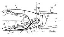
図1に示す一対の爪部材2a、2bは、回動ピボット4を備えるクリップ1を形成するよう互いに関節接合される用意ができており、各爪部材2a、2bを相互に位置決めしながら1つまたは複数のバネ要素6を収容する。バネ要素6は、クリップ1が、例えば、図5aに図示された、クリップ1に外力が加えられている開放状態状態Aから、例えば、図5cに図示された閉鎖状態Bに変形することを可能にする。クリップ1のこの外力が除去されると、動脈瘤を有する組織上でクリップ1が閉鎖され、血管などの残部組織から動脈瘤を隔離することができる。 A pair of
バネ要素6がクリップ1の爪部材2a、2bから突出することなくクリップ1の爪部材2a、2bの内部に完全に一体化されるように、両爪部材2a、2bにはバネ要素6を収容するための開口部12がそれぞれ設けられている。描かれた変形例では、両爪部材2a、2bには、尖頭アーチ型を有し得る開口部12が設けられており、この開口部12にバネ要素6が挿入され、バネ要素の一方の端部9aがこの開口部12の縁部に押し付けられて配置され、他方の端部9bが他方の爪部材2a、2bの出張り部10に形成された窪み部11に配置されることが見てとれる。両爪部材2a、2bの開口部12および窪み部11を有する出張り部10は両者とも対称であり、そのため、両爪部材2a、2bは同じ金型を用いて、例えば、射出によって製造することができ、必要に応じて追加片としてピボットを追加することを強調しておく。 Both the
図1に示す一対の爪部材2a、2bの変形例は、図2に示す方法で互いに関節接合される。爪部材2a、2bは関節接合手段3を備え、この関節接合手段3は、一対の爪部材2a、2bを連結するピボット4の周りでの爪部材2a、2bの回動を可能にすることが見てとれる。この関節接合部3は、描かれた変形例では、一方の爪部材2bのロッド21によって形成され、このロッド21は、図1および図2に示す変形例に図示されるように、ピボット4の形式で他方の爪部材2aの穴22を通過する。図1および図2に示すように、ロッド21がその加圧挿入の後に穴22から抜けることを回避するために、ロッド21は、ロッド21の端子拡大部の形式の保持手段23を備える。また、他の実施形態では、両爪部材2a、2bが穴22を備え、ロッド21は挿入可能な別個の要素であって、一対の爪部材2a、2bを関節式に接合された状態に維持し、例えば、リベットを用いた関節接合部3のピボット4を形成することができることが想定される。また、両方の穴を通過して対応する相手のねじによって保持され、一対の爪部材2a、2bを関節接合状態に維持するねじなど、他の接合手段を使用することもできることが想定される。また、ロッドをリベット留めする代わりに、爪部材は、割りピンまたはスターロックワッシャーなどの端部締結片を備えることもできると考えられる。 A modification of the pair of
一対の爪部材2a、2bは、クランプ面を備えることが見てとれ、このクランプ面は、例えば、図5cにさらに図示されるように、クリップ1の操作閉鎖状態Bにおいて、組織を緊密に閉鎖し、血管から動脈瘤を隔離する役割を果たす。組織上のクリップ1の完全な緊密な閉鎖を達成し、動脈瘤を有する組織の一部を残部組織から隔離しクリップの滑りを防止するように、これらのクランプ面は凸凹であるのが好ましい。例えば、クランプ面は互いに補完的とすることができ、また波状または鋸歯状などクリップの長手方向に対して直交する山と谷のような凸凹を備えることができる。図2では、一対の爪部材2a、2bのそれぞれにおいて、力桿(てこの支点から力点側の部分)5aおよび作用桿(てこの支点から作用点側の部分)5bによって形成されたてこが識別され、ピボット4が2つのてこの支点のように作用することが見てとれる。このようにして、バネ要素6が挿入された後、図3に図示するように、関節接合手段3は、一対の爪部材2a、2bを連結するピボット4の周りでの爪部材の回動を可能にし、クリップ1は少なくとも開放状態Aと閉鎖状態Bとを採ることができ、開放状態Aでは爪部材2a、2bの作用桿5bが離間し、閉鎖状態Bでは爪部材2a、2bの作用桿5bが互いに当接され、動脈瘤を隔離するのに十分な圧力を加えるのに適切である。力桿5aは、外力が印加される部分と定義され、作用桿5bは、アプリケータによって伝達された力を受け取る部分と定義される。 It can be seen that the pair of
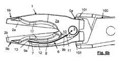
図3では、クリップ1のバネ要素6は、円弧形状部8の部分を有する少なくとも1つの可撓性弾性要素7を備えることが見てとれ、開放状態Aと閉鎖状態Bの両方において、可撓性弾性要素7は、クリップ1の外形から突出することなく一対の爪部材2a、2bに完全に収容される。この可撓性要素7は、クリップ1の開放状態Aおよび閉鎖状態Bの両方において、優弧すなわち馬蹄形弧でない円弧状を有し、すなわち、その曲線はクリップ1の開放状態Aおよび閉鎖状態Bの両方において中心角が180°を超えず、したがって可撓性要素7は、縮小空間を占有する板バネのように機能することが可能となる。また、PEEKなどの放射線透過性材料を注入して、バネ要素6をクリップ1に固定することができることも想定される。 In FIG. 3 it can be seen that the
また、可撓性要素7は長方形かつ薄板状であり、その互いに反対側の端部9a、9bが別々の爪部材2a、2b上に保持されることが見てとれる。他の変形実施形態では、可撓性要素は、ロッド形状など他の長方形状を有することができることも想定される。可撓性要素7は、その端部でのみ爪部材2a、2bに接触していることを強調しておく。図3に示す変形例には2つの円弧薄板状の可撓性要素7が設けられ、クリップ1が一方の側面と他方の側面とで同じ側面視を有するように、各可撓性要素7の前端部9aは、一方の爪部材2a、2bの開口部12の縁部13に収容され、後端部9bは、他方の爪部材2a、2bの出張り部10の窪み部11に収容される。 Further, it can be seen that the
2つの爪部材2a、2bを接合した後の可撓性要素7のクリップ内部への挿入は、可撓性要素7を開口部12に導入することができるまで十分に曲げることによって行うことができる。可撓性要素7はその導入後に解放されると、開口部12の縁部13と出張り部の窪み部11との間で保持され、図3に示すクリップ1を閉鎖状態Bに強制する。あるいは、可撓性要素7は、一対の爪要素2a、2bの間の後部分離チャネル15を用いて導入することができ、この方法では、可撓性要素7は、一方の端部9aが縁部13に当接されるまで導入されるべきであり、他方の端部が開口部12に当接されるまで可撓性要素を曲げるように可撓性要素の押し込みを継続する。この後部チャネル15の使用は、開口部12に横方向保持手段14が設けられている場合に有利であり、側方保持手段14は、それが収容されている開口部12から可撓性要素7が側方に突出すること、また側方に抜け出ることも防止する。もちろん、これらの横方向保持手段14は、可撓性要素7の開口部12への側方からの進入を可能にすることもできるが、可撓性要素7の抜けを可能にすることはできない。例えば、これらの手段は、この可撓性要素7の進入を可能にするために十分に曲げることができる舌部であるが、開口12からの可撓性要素7の抜け出しを可能にすることはできない。側方保持手段14が、例えば、開口部12を横断方向に完全に横切る帯状部材であると想定される場合には、クリップ1には可撓性要素7を導入するための後部チャネル15を設けるべきである。もちろん、クリップ1がクリップ1の各側面に1つずつ配置された、2つの可撓性要素7を備える場合、各可撓性要素に対して1つずつ、2つの後部チャネル15が必要である。 Insertion of the
図3では、互いに直交するクリップ1の水平方向切断面Hおよび垂直方向切断面Fも図示されており、それらはピボット4の中心で交差し、2つの可撓性要素7はそれぞれ、閉鎖状態Bにおいて、1つの象限内に配置されることが見てとれる。以下から分かるように、可撓性要素7はそれぞれ、開放状態Aに変化する際に閉鎖状態Bと同じ象限内の所定の位置に維持される。爪部材2a、2bの材料およびバネ要素6の材料の両方が生体適合性であり、すなわち、それにより患者の体内への差し込みが可能であることが想定される。もちろん、部品のいくつかが生体適合性でない場合、危険をもたらさないようにそれらを生体適合性材料内に収容または封入することが可能であることも考えられる。 Also shown in FIG. 3 is a horizontal cut surface H and a vertical cut surface F of the
バネ要素6を形成する可撓性要素7は、好ましくは、連続炭素繊維を用いた材料からなる薄板によって形成され、この連続炭素繊維は、耐久性および生体適合性を有することに加え、クリップ1を閉鎖状態に維持するのに十分な力を達成することを可能にする。他の変形実施形態では、バネ要素6においてロッドなど他の形状の連続炭素繊維を有する材料の使用が検討される。有利には、バネ要素6を形成する可撓性要素7は、突出せずに開口12内に収容されるとき、必ずしも生体適合性でなくてもよく、この方法では、可撓性要素7は、適切な機械的特性を有する繊維ガラスなど、生体適合性を有するとは考えられない材料で作製することができると考えられる。生体適合性ではないと考えられるこれらの材料を、例えば、生体適合性樹脂などの生体適合性材料に封入することもできる。もちろん、バネ要素6が適切な機械的特性を有していれば、ポリマーまたは繊維強化ポリマーなどの他の材料で作製することができることも想定される。 The
図3に一対の後方矢印Faが描かれており、これらは、図3に示す閉鎖状態Bから開放状態Aに変化させるために爪部材2a、2bの力桿5aに加えられる外力を表す。この外力は、以下に説明するように、カップ部19によって形成されたそれぞれの支持領域18に加えられるのが好ましい。このように、爪部材2a、2bで形成されるてこと、てこの支点のように作用するピボット4とを用いて、一対の前方矢印Fbで描かれたように爪部材2a、2bの作用桿5bに力を加えて、それらを離間させて開放状態Aを採る。クリップ1には、図3に図示されたようなクリップ1の閉鎖状態Bにおいて初めは離間している停止面16が設けられ、以下から分かるように、停止面16は、開放状態Aにおいて互いに当接し、それによってクリップ1の開口を制限することが想定される。 A pair of rear arrows Fa are depicted in FIG. 3, and these represent external forces applied to the
先に図3に示したクリップ1が、図4では個々の部分が組み付け時の状態を維持して互いに関連をもって図示されている。ここでは、クリップ1が、円弧形状部8を有する部分を備えた2つの可撓性要素7によって形成されていることが分かる。2つの可撓性要素7は、各爪部材2a、2bに設けられたそれぞれの開口部12に導入され、また、クリップ1の両側に配置され、クリップ1の内部において対称配置される。このように、クリップ1は対称的であることがみてとれる。 The
好ましくは、可撓性要素7を形成する薄板は、予め張力をかけられ、円弧形状部8を有する少なくとも1つの部分を有する。可撓性要素7全体が円弧形状部8を有する単一部分を形成することが想定されているが、いくつかの円弧状部分もあり得るし、あるいは可撓性要素に直線補強端部を設けることができる。可撓性要素が、ループを生成することなく各爪部材2a、2bの開口部12に完全に収容されることができ、円弧状バネのように、すなわち板バネのように作用するように、クリップ1の開放状態Aと閉鎖状態Bの両方において、可撓性要素7の円弧形状部8を有する部分の両端部における2本の接線の交点は、90度より大きい角度αを決定することが想定される。また、可撓性要素7の円弧形状部8を有する部分は、クリップ1の開放状態Aおよび閉鎖状態Bの両方で同じ方向に凹みを有し、したがって可撓性要素を爪部材2a、2bの間に圧入することが常に可能になることが見てとれる。 Preferably, the lamina forming the
前述のように、クリップ1にはカップ部19によって形成された支持領域18が設けられ、支持領域18は、外力を受け、閉鎖状態Bから組織内への配置に適切な開放状態Aに変形するためのものである。動脈瘤上にクリップ1を配置した後、外力が除去されると、再び閉鎖状態Bをとって、動脈瘤を隔離する。アプリケータがこの支持領域に図5aに図示されたように圧力を加えるとクリップがその閉鎖状態Bから開放状態Aに回動するように、これらのカップ部19は、爪部材2a、2bの力桿5a上の、アプリケータ100と協働するのに適合した支持領域18を決定する。 As described above, the
外科医は、爪部材2a、2bの力桿5aの停止面16が互いに当接してクリップ1の開口を制限する開放状態Aをクリップが採るようにクリップ1とアプリケータ100とを接合した後、クリップ1を組織上に配置することができる。動脈瘤を簡便に隔離するために組織の緊密な閉鎖を実行するための高い正確性が達成されるように、爪部材2a、2bの厚さがその前端部でその後端部よりも薄いことに加えて、クリップ1には、外科医が見やすくなるように、両側に側面凹部17が設けられると都合が良い。 The surgeon joins the
外科医は、クランプ対象である組織上にクリップ1を適切に配置した後、アプリケータ100を作動して支持領域に作用する外力を徐々に除去し、バネ要素6による力が作用すると、図5bに示す中間状態を通過した後、クリップ1は図5cに示す閉鎖状態Bを採る。この時点で、外科医は、アプリケータ100をクリップ1から完全に解放してアプリケータ100を取り外すことができ、クリップ1は都合良く配置され、動脈瘤の緊密な閉鎖を実行する。 After appropriately placing the
バネ要素6を形成する可撓性要素7は、クリップ1が閉鎖状態Bを採るときに動脈瘤の閉鎖を正確に維持することができるように、寸法決めされかつクリップ1に配置されなければならない。この動脈瘤の緊密な閉鎖を達成するために、クリップ1は、図5cに示す閉鎖状態Bを採るとき、約180グラムの動脈瘤に作用する閉鎖力を付与する必要がある。 The
この効果を達成するために、可撓性要素7の厚さ(e)、クリップ1のクランプ面の長さ(b)、および可撓性要素7の材料の弾性係数(E)は、理想的には、次の方程式に従うべきである。
弾性係数(E)は各材料に依存し、この弾性係数(E)は、例えば、チタンでは110GPa、ステンレス鋼では210GPa、繊維と整列した(fiber-aligned)ENDOLIGNでは150GPaであり、繊維方向に垂直なENDOLIGNでは9.4GPa、PEEK−30CFでは18GPaである。このようにして、クリップ1のクランプ面の長さ(b)に適した、可撓性要素7の厚さ(e)を得ることができる材料が選択される。 The elastic modulus (E) depends on each material, and this elastic modulus (E) is, for example, 110 GPa for titanium, 210 GPa for stainless steel, 150 GPa for fiber-aligned ENDOLIGN, and perpendicular to the fiber direction. In ENDOLIGN, it is 9.4 GPa, and in PEEK-30CF, it is 18 GPa. In this way, a material is selected that can obtain the thickness (e) of the
可撓性要素7の寸法は、クリップ1が屈曲して閉鎖状態Bを採るように、最大開口時、すなわち、クリップ1がその開放状態Aを採るときに可撓性要素7がその弾性範囲内に維持されることを可能にすることが必要である。これは、バネ要素の幅がバネ要素の厚さ(e)の5〜10倍であり、クリップ1の閉鎖状態Bにおける可撓性要素7の弧の弦長がバネ要素の厚さ(e)の20〜60倍であるときに生じることが認められた。 The dimensions of the
前述の制限を考慮すると、クランプ面の長さ(b)を9mmとし、繊維と整列したENDOLIGNを材料として使用すると、可撓性要素7の厚さ(e)が0.05〜0.5ミリメートルであり、それによって可撓性要素7の幅(a)が2ミリメートル未満、例えば0.25〜2ミリメートルとなり、可撓性要素7の弧の弦長(l)が4〜12ミリメートルとなることを達成するときに良好な妥協が得られたと判断される。これらの寸法によって可撓性要素7を小さな寸法を有するクリップ1内に配置することが可能になり、動脈瘤を閉鎖状態に維持するのに十分な閉鎖力をクリップ1に提供し、また同時に可撓性要素7は、最大開口時にその弾性範囲内に維持される。この効果を増強するために、出張り部10の窪み部11である可撓性要素7の支持点と、クリップ1の回動ピボット4の中心との間の半径は、0.5〜3ミリメートルであるのが好ましい。 Considering the above-mentioned limitations, when the length (b) of the clamping surface is 9 mm and ENDOLIG aligned with the fiber is used as the material, the thickness (e) of the
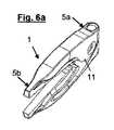
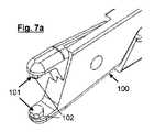
図6a、図6b、および図6cはクリップ1の詳細を示し、これらの図において、カップ部19には、アプリケータ100の本質的に半球形の端部101を受け入れるように適合された2つの平行平面20a、20bが設けられるのが都合が良く、アプリケータ100には、一組の平行平面102が設けられ、クリップ1の2つの平行平面20a、20bがアプリケータ100の本質的に半球形の端部101に対してどのように配置されるかによってクリップ1を別の向きに配置することができるように、これらの平行面102は、図7aおよび図7bに図示されたように多角柱を形成することが見てとれる。図示された変形例では、アプリケータ100の一組の平行平面102が八角形を形成しているが、クリップは、アプリケータと一列に整列して配置することに加えて、右または左に45度または90度回転して配置することができる。もちろん、より多くの面を有する多角形を使用して、クリップ1がアプリケータ100に関して採り得る角度をより細かくすることができることが想定される。 FIGS. 6a, 6b and 6c show details of the
クリップ1のいろいろな変形例では、撮像画像におけるクリップの有無を明確に識別できるように、X線に対してまたは画像を取得するために使用される他の放射線に対して不透明な材料でマークされた1つまたは複数の片を備えることができることが想定される。このマーク片は、例えば、爪部材2a、2bの少なくとも一方に埋め込まれた小球体または金属繊維とすることができる。また、マーク片は2つの爪部材2a、2bの間に挿入されたワッシャーとすることができるか、または上記ピボット4が金属であり、したがってマーク片のように作用することが想定される。 Various variations of
マーク片は、超音波を用いて適用される、2つの爪部材2a、2bの少なくとも一方への金属製はめ込みとすることができる。また、爪部1には、クリップ1のいくつかの製造工程中にポリマーと混合される放射線不透過性化合物など多量のX線不透過性材料を備えることができることが想定される。 The mark piece can be made of metal fitting into at least one of the two
また、クリップ1の側方断面図を描いた図6bには、クリップ1の2つの可撓性要素7の各々を収容する各爪部材2a、2bの開口部12および窪み部11を見てとることができることを強調しておく。この断面図では、クリップ1の対称性を見てとることができ、これは他の図では隠れているかもしれない。 Also, in FIG. 6 b depicting a side sectional view of the
クリップ1をアプリケータ100に結合した後に図8に示すキット200を形成するように、クリップ1のカップ部19の2つの平行平面20a、20bの間の間隔は、アプリケータ100の本質的に半球状の端部101の平行平面102同士の間の間隔よりも大きいことが想定される。例えば、アプリケータ100が先に図7a、図7bに示したアプリケータであり、またクリップ1がアプリケータと初めに位置合わせされる場合、45度の傾きで安定した姿勢を得ることができるように、また、一定の圧力が加え続けられたときに到達する傾きが90度であるように、外科医は、アプリケータ100に対するクリップ1の回転を修正して、クリップ1に所定の圧力を加えることができる。もちろん、クリップ1のカップ部19の2つの平行平面20a、20bの間の間隔は、クリップ1の姿勢の安定性に影響を及ぼすことなくこの任意選択の回転の効果を達成することができるように計算されるべきである。この回転効果がないクリップ1とアプリケータ100とからなるキット200を設計することも可能であり、クリップ1の支持領域18は、例えば図9に示すアプリケータのような既知のアプリケータとの互換性がある。 The distance between the two
図9は、クリップ1の代替的変形実施形態を示しており、図3に示された先の変形例とは違い、爪部材2a、2bが交差し、これによって各爪部材2a、2bの作用桿5bの開口方向が、対応する力桿5aに印加される力の方向と一致することが可能になる。このようにして、その後部に接合歯が設けられたクリップ1の変形例が達成され、これは既知のアプリケータとの使用に適している。また、図9に示す変形例には、横方向保持手段15も図示されており、開口部12を通り抜ける、可撓性要素7が突出するのを防ぐ帯状部材の形態で示されている。 FIG. 9 shows an alternative variant embodiment of the
図10はクリップ1の代替的変形実施形態を示し、図10では、可撓性要素7が、窪み部11が位置する部材の後端部に達している。図11は、図10のクリップと類似のクリップの別の変形例を示し、可撓性要素が爪部材の一方内にオーバーインジェクションされている。図10および図11の変形例では、バネ要素6の可撓性要素7は、クリップ内に部分的に収容され、クリップ1の輪郭、すなわちクリップ1が包含されている空間(具体的には、一対の連結爪部材2a、2b)から突き出ることなく、圧入されている。図12〜図17は他の動脈瘤用クリップ1を示す。 FIG. 10 shows an alternative variant embodiment of the
図12はクリップ1を示し、その爪部材2a、2bは単一片によって形成されており、クリップ1は、クリップの前部に向かって配向されたC字状の可撓性要素7によって形成された外部バネ要素6を備え、この外部バネ要素6はクリップの後部を取り囲んでいる。別のクリップでは、2つの爪部をピンを用いて接合することができ、バネ要素6が中央部分で2つの爪部を通り抜ける。 FIG. 12 shows a
図13は、爪部材2a、2bから突出したC字状の可撓性要素7によって形成されたバネ要素6を備える別のクリップ1を示す。バネ要素6は、クリップの側部にはんだ付けするかまたはクリップ内に導入することができ、爪部2a、2bには、バネ要素を導入するハウジングが設けられることになる。このクリップの開口は、アプリケータが後部に開口力を加えるときに実行されることになる。 FIG. 13 shows another
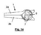
図14は、可撓性要素7であるバネ要素6が爪部材2a、2bに収容されている別のクリップ1を示しており、バネ要素6は、図14に示された閉鎖状態において真っ直ぐな状態を採る。このクリップ1において、2つのバネ要素6が、その一方の端部で一方の爪部材2aの端部に固定され、他方の端部は自由であり他方の爪部材2bに当接される。このようにして、バネ要素6の自由端はカム形状(cam geometry)と擦れ合い、クリップ1が開口されるときに力が印可される爪部材2bに力を加えることが可能になる。 FIG. 14 shows another
図15は、可撓性要素7によって形成されるバネ要素6が、一方の爪部材2bに固定されて他方の爪部材2aに当接される別のクリップ1を示し、バネ手段は、図14に示す閉鎖状態において真っ直ぐな状態を採る。 FIG. 15 shows another
図16は、爪部材2a、2bによってバネ要素6が形成された別のクリップ1を示しており、すなわち、バネ要素6は爪部材2a、2bと共に成形され、したがって同じ材料で作製されている。このクリップでは、爪部2aにピンが設けられ、これらのピンは、爪部2bのタブと相互作用して、クリップの爪部に加えられる力を引き起こす。 FIG. 16 shows another
図17は別のクリップ1を示し、このクリップ1では、バネ要素6は、爪部材2a、2bの外側に接着された可撓性要素7である。この場合、可撓性要素7はクリップの前部に固定され、その後部は自由であり、クリップ1の開口中に外側に向かって弧を描くことが可能となり、したがって閉鎖力を生成する。
FIG. 17 shows another
Claims (35)
Translated fromJapanese前記爪部材同士を関節接合する手段(3)とを備える動脈瘤用クリップ(1)であって、
前記関節接合する手段は、前記一対の爪部材を連結するピボットの周りでの前記一対の爪部材の回動を可能にし、 力桿(5a)および作用桿(5b)が各爪部材上で分けられ、
前記クリップは、少なくとも、
前記爪部材同士の前記作用桿が互いに離間される開放状態(A)と、
前記爪部材同士の前記作用桿が互いに当接される閉鎖状態(B)とを採ることができるように構成され、
前記クリップには前記クリップを前記閉鎖状態に配置するように屈曲する少なくとも1つのバネ要素(6)が設けられ、
前記少なくとも1つのバネ要素は、前記クリップに少なくとも部分的に収容され、円弧形状部(8)を有する部分を有する可撓性弾性要素(7)を備え、
前記可撓性弾性要素は、前記開放状態および前記閉鎖状態の両方において、2つの互いに反対側の端部(9a,9b)が、それぞれ、別の爪部材に圧力を加えて圧入されていることを特徴とする、クリップ。A pair of claw members (2a, 2b) made of a non-metallic material;
An aneurysm clip (1) comprising means (3) for articulating the nail members,
The articulating means enables the pair of claw members to be rotated around a pivot connecting the pair of claw members, and the force lever (5a) and the action rod (5b) are divided on each claw member. And
The clip is at least
An open state (A) in which the working rods of the claw members are separated from each other;
It is constituted so that it can take a closed state (B) where the above-mentioned action rod of the above-mentioned claw members contacts each other,
The clip is provided with at least one spring element (6) that bends to place the clip in the closed state;
The at least one spring element comprises a flexible elastic element (7) having a portion at least partially housed in the clip and having an arcuate portion (8);
In the flexible elastic element, in both the open state and the closed state, two opposite end portions (9a, 9b) are respectively press-fitted by applying pressure to another claw member. Features a clip.
前記クリップは、前記爪部材(2a,2b)の前記力桿(5a)上に支持領域(18)を備え、
前記アプリケータが前記支持領域に圧力を加えると前記クリップが前記閉鎖状態(B)から前記開放状態(A)に回動するように、前記支持領域は、前記アプリケータ(100)と協働するよう適合されることを特徴とする、キット(200)。A kit (200) formed by the clip (1) according to any one of claims 1 to 32 and an applicator (100) for articulating the clip,
The clip includes a support region (18) on the force lever (5a) of the claw member (2a, 2b),
The support region cooperates with the applicator (100) such that when the applicator applies pressure to the support region, the clip rotates from the closed state (B) to the open state (A). Kit (200), characterized in that it is adapted as follows.
Applications Claiming Priority (3)
| Application Number | Priority Date | Filing Date | Title |
|---|---|---|---|
| ESP201431951 | 2014-12-30 | ||
| ES201431951AES2575727B1 (en) | 2014-12-30 | 2014-12-30 | Aneurysm clamp |
| PCT/ES2015/070957WO2016107952A1 (en) | 2014-12-30 | 2015-12-28 | Clip for aneurysm |
Publications (3)
| Publication Number | Publication Date |
|---|---|
| JP2018500134Atrue JP2018500134A (en) | 2018-01-11 |
| JP2018500134A5 JP2018500134A5 (en) | 2018-12-13 |
| JP6722674B2 JP6722674B2 (en) | 2020-07-15 |
Family
ID=55299491
Family Applications (1)
| Application Number | Title | Priority Date | Filing Date |
|---|---|---|---|
| JP2017534935AExpired - Fee RelatedJP6722674B2 (en) | 2014-12-30 | 2015-12-28 | Clip for aneurysm |
Country Status (6)
| Country | Link |
|---|---|
| US (1) | US10743885B2 (en) |
| EP (1) | EP3241508B1 (en) |
| JP (1) | JP6722674B2 (en) |
| CN (1) | CN107106183B (en) |
| ES (1) | ES2575727B1 (en) |
| WO (1) | WO2016107952A1 (en) |
Families Citing this family (2)
| Publication number | Priority date | Publication date | Assignee | Title |
|---|---|---|---|---|
| EP3461435B1 (en) | 2017-09-28 | 2019-09-04 | Lazic Besitz GmbH & Co. KG | Surgical clip made from carbon fibre reinforced plastic material |
| US12433710B1 (en) | 2024-06-17 | 2025-10-07 | Ohio State Innovation Foundation | Device to restrain opening of an off-the-shelf surgical instrument |
Citations (7)
| Publication number | Priority date | Publication date | Assignee | Title |
|---|---|---|---|---|
| US4324248A (en)* | 1980-05-30 | 1982-04-13 | Metatech Corporation | Microsurgical clip |
| JPS5810037A (en)* | 1981-04-13 | 1983-01-20 | メタテツク・コ−ポレ−シヨン | Clip for microscopic operation |
| JPS6124807A (en)* | 1984-06-29 | 1986-02-03 | バクスター インターナショナル インコーポレーテッド | Improved clip |
| US4813107A (en)* | 1987-09-04 | 1989-03-21 | Warren Tool Corporation | Spring clamp |
| US20040254596A1 (en)* | 2003-06-16 | 2004-12-16 | Synovis Life Technologies, Inc. | Vascular clamp |
| US20060195125A1 (en)* | 2003-03-06 | 2006-08-31 | Ghassan Sakakine | Spring clip and method for assembling same |
| US20140142597A1 (en)* | 2012-11-21 | 2014-05-22 | Atricure, Inc. | Occlusion clip |
Family Cites Families (4)
| Publication number | Priority date | Publication date | Assignee | Title |
|---|---|---|---|---|
| US4147167A (en)* | 1976-08-05 | 1979-04-03 | Horst R. Hickmann | Ophthalmic prosthesis implant instrument |
| CA2587267A1 (en)* | 2006-04-29 | 2007-10-29 | James B. Klassen | Surgical clip, applicator, and applicator methods |
| US20110224700A1 (en)* | 2010-03-09 | 2011-09-15 | Teleflex Medical Incorporated | Narrow Profile Surgical Ligation Clip |
| WO2013142443A1 (en)* | 2012-03-19 | 2013-09-26 | Litherland Craig Michael | Zero artifact vascular clip method and apparatus |
- 2014
- 2014-12-30ESES201431951Apatent/ES2575727B1/ennot_activeExpired - Fee Related
- 2015
- 2015-12-28CNCN201580071809.6Apatent/CN107106183B/ennot_activeExpired - Fee Related
- 2015-12-28JPJP2017534935Apatent/JP6722674B2/ennot_activeExpired - Fee Related
- 2015-12-28EPEP15831144.9Apatent/EP3241508B1/enactiveActive
- 2015-12-28USUS15/540,635patent/US10743885B2/ennot_activeExpired - Fee Related
- 2015-12-28WOPCT/ES2015/070957patent/WO2016107952A1/enactiveApplication Filing
Patent Citations (7)
| Publication number | Priority date | Publication date | Assignee | Title |
|---|---|---|---|---|
| US4324248A (en)* | 1980-05-30 | 1982-04-13 | Metatech Corporation | Microsurgical clip |
| JPS5810037A (en)* | 1981-04-13 | 1983-01-20 | メタテツク・コ−ポレ−シヨン | Clip for microscopic operation |
| JPS6124807A (en)* | 1984-06-29 | 1986-02-03 | バクスター インターナショナル インコーポレーテッド | Improved clip |
| US4813107A (en)* | 1987-09-04 | 1989-03-21 | Warren Tool Corporation | Spring clamp |
| US20060195125A1 (en)* | 2003-03-06 | 2006-08-31 | Ghassan Sakakine | Spring clip and method for assembling same |
| US20040254596A1 (en)* | 2003-06-16 | 2004-12-16 | Synovis Life Technologies, Inc. | Vascular clamp |
| US20140142597A1 (en)* | 2012-11-21 | 2014-05-22 | Atricure, Inc. | Occlusion clip |
Also Published As
| Publication number | Publication date |
|---|---|
| CN107106183A (en) | 2017-08-29 |
| CN107106183B (en) | 2019-11-29 |
| US10743885B2 (en) | 2020-08-18 |
| EP3241508A1 (en) | 2017-11-08 |
| JP6722674B2 (en) | 2020-07-15 |
| US20180008275A1 (en) | 2018-01-11 |
| EP3241508B1 (en) | 2020-02-26 |
| ES2575727B1 (en) | 2017-04-12 |
| WO2016107952A1 (en) | 2016-07-07 |
| ES2575727A1 (en) | 2016-06-30 |
Similar Documents
| Publication | Publication Date | Title |
|---|---|---|
| JP6876821B2 (en) | Clip applier with replaceable tip | |
| US11284904B2 (en) | Clip treatment tool | |
| JP6571044B2 (en) | Surgical staples for compressing bone or bone fragments, and assemblies comprising surgical staples and instruments for holding them | |
| CN110740695B (en) | Surgical Clips and Clip Appliers | |
| EP3600077B1 (en) | Clip applier having stabilizing member | |
| CN110868944B (en) | Flexible stabilizing member for clip applier | |
| US9962195B2 (en) | Bone holding device | |
| JP6669729B2 (en) | Independent interbody implant | |
| US20110224700A1 (en) | Narrow Profile Surgical Ligation Clip | |
| US20060264973A1 (en) | Orthopedic implant bender | |
| CN108852451A (en) | Spring release type accessory clamp | |
| US20130245653A1 (en) | Zero artifact vascular clip method and apparatus | |
| US3911926A (en) | Adjustable microvascular U-clamp | |
| US20160051260A1 (en) | System for joining two blood vessels | |
| CN106794067A (en) | Cup impactor | |
| EP3821826A1 (en) | Multi-part ligation clip | |
| CN109864772A (en) | Microsurgical instruments and improvements in handles | |
| JP2018500134A (en) | Aneurysm clip | |
| JP2023500185A (en) | clip applier | |
| CN110769765A (en) | Fixture handling device | |
| US8495902B2 (en) | Crimping device | |
| WO2025162513A1 (en) | Surgical fixation clamp | |
| JP7630506B2 (en) | Implant System | |
| US11517424B2 (en) | Tool for molding dysphonia treatment tool, and method for bending front piece of dysphonia treatment tool | |
| TW202123889A (en) | Anchors and tensioner and anchor loading systems for active bone and joint stabilization devices |
Legal Events
| Date | Code | Title | Description |
|---|---|---|---|
| A521 | Request for written amendment filed | Free format text:JAPANESE INTERMEDIATE CODE: A523 Effective date:20181030 | |
| A621 | Written request for application examination | Free format text:JAPANESE INTERMEDIATE CODE: A621 Effective date:20181030 | |
| A131 | Notification of reasons for refusal | Free format text:JAPANESE INTERMEDIATE CODE: A131 Effective date:20190827 | |
| A977 | Report on retrieval | Free format text:JAPANESE INTERMEDIATE CODE: A971007 Effective date:20190823 | |
| A521 | Request for written amendment filed | Free format text:JAPANESE INTERMEDIATE CODE: A523 Effective date:20191120 | |
| TRDD | Decision of grant or rejection written | ||
| A01 | Written decision to grant a patent or to grant a registration (utility model) | Free format text:JAPANESE INTERMEDIATE CODE: A01 Effective date:20200602 | |
| A61 | First payment of annual fees (during grant procedure) | Free format text:JAPANESE INTERMEDIATE CODE: A61 Effective date:20200622 | |
| R150 | Certificate of patent or registration of utility model | Ref document number:6722674 Country of ref document:JP Free format text:JAPANESE INTERMEDIATE CODE: R150 | |
| R250 | Receipt of annual fees | Free format text:JAPANESE INTERMEDIATE CODE: R250 | |
| LAPS | Cancellation because of no payment of annual fees |