JP2018205448A - Display device and lighting device - Google Patents
Display device and lighting deviceDownload PDFInfo
- Publication number
- JP2018205448A JP2018205448AJP2017108816AJP2017108816AJP2018205448AJP 2018205448 AJP2018205448 AJP 2018205448AJP 2017108816 AJP2017108816 AJP 2017108816AJP 2017108816 AJP2017108816 AJP 2017108816AJP 2018205448 AJP2018205448 AJP 2018205448A
- Authority
- JP
- Japan
- Prior art keywords
- light
- half mirror
- image
- image light
- incident
- Prior art date
- Legal status (The legal status is an assumption and is not a legal conclusion. Google has not performed a legal analysis and makes no representation as to the accuracy of the status listed.)
- Pending
Links
- 230000010287polarizationEffects0.000claimsabstractdescription156
- 238000005286illuminationMethods0.000claimsdescription32
- 230000005540biological transmissionEffects0.000claimsdescription26
- 230000004907fluxEffects0.000claimsdescription6
- 230000003287optical effectEffects0.000description113
- 239000004973liquid crystal related substanceSubstances0.000description30
- 230000004048modificationEffects0.000description24
- 238000012986modificationMethods0.000description24
- 238000002834transmittanceMethods0.000description23
- 238000010586diagramMethods0.000description18
- 239000010408filmSubstances0.000description15
- 230000000694effectsEffects0.000description13
- 239000000758substrateSubstances0.000description11
- 230000009471actionEffects0.000description9
- 239000011521glassSubstances0.000description5
- 229910010413TiO 2Inorganic materials0.000description4
- 230000007423decreaseEffects0.000description4
- 239000000463materialSubstances0.000description4
- 239000011347resinSubstances0.000description4
- 229920005989resinPolymers0.000description4
- 238000007493shaping processMethods0.000description4
- 229910018072Al 2 O 3Inorganic materials0.000description3
- 238000002347injectionMethods0.000description3
- 239000007924injectionSubstances0.000description3
- 229910052751metalInorganic materials0.000description3
- 239000002184metalSubstances0.000description3
- 238000002310reflectometryMethods0.000description3
- 230000008859changeEffects0.000description2
- 239000013078crystalSubstances0.000description2
- 230000005855radiationEffects0.000description2
- 239000012790adhesive layerSubstances0.000description1
- 229910052782aluminiumInorganic materials0.000description1
- XAGFODPZIPBFFR-UHFFFAOYSA-NaluminiumChemical compound[Al]XAGFODPZIPBFFR-UHFFFAOYSA-N0.000description1
- 238000005452bendingMethods0.000description1
- 230000015572biosynthetic processEffects0.000description1
- 239000000470constituentSubstances0.000description1
- 230000007547defectEffects0.000description1
- 230000002999depolarising effectEffects0.000description1
- 238000005516engineering processMethods0.000description1
- 239000000284extractSubstances0.000description1
- 238000000605extractionMethods0.000description1
- 210000003128headAnatomy0.000description1
- 238000009434installationMethods0.000description1
- 239000010410layerSubstances0.000description1
- 239000011159matrix materialSubstances0.000description1
- 238000000034methodMethods0.000description1
- 230000001902propagating effectEffects0.000description1
- 210000001747pupilAnatomy0.000description1
- 210000001525retinaAnatomy0.000description1
- 230000002207retinal effectEffects0.000description1
- 239000010409thin filmSubstances0.000description1
- 238000007740vapor depositionMethods0.000description1
- 230000000007visual effectEffects0.000description1
Images


Classifications
- G—PHYSICS
- G02—OPTICS
- G02F—OPTICAL DEVICES OR ARRANGEMENTS FOR THE CONTROL OF LIGHT BY MODIFICATION OF THE OPTICAL PROPERTIES OF THE MEDIA OF THE ELEMENTS INVOLVED THEREIN; NON-LINEAR OPTICS; FREQUENCY-CHANGING OF LIGHT; OPTICAL LOGIC ELEMENTS; OPTICAL ANALOGUE/DIGITAL CONVERTERS
- G02F1/00—Devices or arrangements for the control of the intensity, colour, phase, polarisation or direction of light arriving from an independent light source, e.g. switching, gating or modulating; Non-linear optics
- G02F1/01—Devices or arrangements for the control of the intensity, colour, phase, polarisation or direction of light arriving from an independent light source, e.g. switching, gating or modulating; Non-linear optics for the control of the intensity, phase, polarisation or colour
- G02F1/13—Devices or arrangements for the control of the intensity, colour, phase, polarisation or direction of light arriving from an independent light source, e.g. switching, gating or modulating; Non-linear optics for the control of the intensity, phase, polarisation or colour based on liquid crystals, e.g. single liquid crystal display cells
- G02F1/133—Constructional arrangements; Operation of liquid crystal cells; Circuit arrangements
- G02F1/1333—Constructional arrangements; Manufacturing methods
- G02F1/1335—Structural association of cells with optical devices, e.g. polarisers or reflectors
- G02F1/1336—Illuminating devices
- G02F1/13362—Illuminating devices providing polarized light, e.g. by converting a polarisation component into another one
- G—PHYSICS
- G02—OPTICS
- G02B—OPTICAL ELEMENTS, SYSTEMS OR APPARATUS
- G02B27/00—Optical systems or apparatus not provided for by any of the groups G02B1/00 - G02B26/00, G02B30/00
- G02B27/01—Head-up displays
- G02B27/017—Head mounted
- G02B27/0172—Head mounted characterised by optical features
- G—PHYSICS
- G02—OPTICS
- G02B—OPTICAL ELEMENTS, SYSTEMS OR APPARATUS
- G02B27/00—Optical systems or apparatus not provided for by any of the groups G02B1/00 - G02B26/00, G02B30/00
- G02B27/10—Beam splitting or combining systems
- G02B27/14—Beam splitting or combining systems operating by reflection only
- G02B27/144—Beam splitting or combining systems operating by reflection only using partially transparent surfaces without spectral selectivity
- G—PHYSICS
- G02—OPTICS
- G02F—OPTICAL DEVICES OR ARRANGEMENTS FOR THE CONTROL OF LIGHT BY MODIFICATION OF THE OPTICAL PROPERTIES OF THE MEDIA OF THE ELEMENTS INVOLVED THEREIN; NON-LINEAR OPTICS; FREQUENCY-CHANGING OF LIGHT; OPTICAL LOGIC ELEMENTS; OPTICAL ANALOGUE/DIGITAL CONVERTERS
- G02F1/00—Devices or arrangements for the control of the intensity, colour, phase, polarisation or direction of light arriving from an independent light source, e.g. switching, gating or modulating; Non-linear optics
- G02F1/01—Devices or arrangements for the control of the intensity, colour, phase, polarisation or direction of light arriving from an independent light source, e.g. switching, gating or modulating; Non-linear optics for the control of the intensity, phase, polarisation or colour
- G02F1/13—Devices or arrangements for the control of the intensity, colour, phase, polarisation or direction of light arriving from an independent light source, e.g. switching, gating or modulating; Non-linear optics for the control of the intensity, phase, polarisation or colour based on liquid crystals, e.g. single liquid crystal display cells
- G02F1/133—Constructional arrangements; Operation of liquid crystal cells; Circuit arrangements
- G02F1/1333—Constructional arrangements; Manufacturing methods
- G02F1/1335—Structural association of cells with optical devices, e.g. polarisers or reflectors
- G02F1/133528—Polarisers
- G—PHYSICS
- G02—OPTICS
- G02F—OPTICAL DEVICES OR ARRANGEMENTS FOR THE CONTROL OF LIGHT BY MODIFICATION OF THE OPTICAL PROPERTIES OF THE MEDIA OF THE ELEMENTS INVOLVED THEREIN; NON-LINEAR OPTICS; FREQUENCY-CHANGING OF LIGHT; OPTICAL LOGIC ELEMENTS; OPTICAL ANALOGUE/DIGITAL CONVERTERS
- G02F1/00—Devices or arrangements for the control of the intensity, colour, phase, polarisation or direction of light arriving from an independent light source, e.g. switching, gating or modulating; Non-linear optics
- G02F1/01—Devices or arrangements for the control of the intensity, colour, phase, polarisation or direction of light arriving from an independent light source, e.g. switching, gating or modulating; Non-linear optics for the control of the intensity, phase, polarisation or colour
- G02F1/13—Devices or arrangements for the control of the intensity, colour, phase, polarisation or direction of light arriving from an independent light source, e.g. switching, gating or modulating; Non-linear optics for the control of the intensity, phase, polarisation or colour based on liquid crystals, e.g. single liquid crystal display cells
- G02F1/133—Constructional arrangements; Operation of liquid crystal cells; Circuit arrangements
- G02F1/1333—Constructional arrangements; Manufacturing methods
- G02F1/1335—Structural association of cells with optical devices, e.g. polarisers or reflectors
- G02F1/1336—Illuminating devices
- G02F1/133602—Direct backlight
- G02F1/133605—Direct backlight including specially adapted reflectors
- G—PHYSICS
- G02—OPTICS
- G02F—OPTICAL DEVICES OR ARRANGEMENTS FOR THE CONTROL OF LIGHT BY MODIFICATION OF THE OPTICAL PROPERTIES OF THE MEDIA OF THE ELEMENTS INVOLVED THEREIN; NON-LINEAR OPTICS; FREQUENCY-CHANGING OF LIGHT; OPTICAL LOGIC ELEMENTS; OPTICAL ANALOGUE/DIGITAL CONVERTERS
- G02F1/00—Devices or arrangements for the control of the intensity, colour, phase, polarisation or direction of light arriving from an independent light source, e.g. switching, gating or modulating; Non-linear optics
- G02F1/01—Devices or arrangements for the control of the intensity, colour, phase, polarisation or direction of light arriving from an independent light source, e.g. switching, gating or modulating; Non-linear optics for the control of the intensity, phase, polarisation or colour
- G02F1/13—Devices or arrangements for the control of the intensity, colour, phase, polarisation or direction of light arriving from an independent light source, e.g. switching, gating or modulating; Non-linear optics for the control of the intensity, phase, polarisation or colour based on liquid crystals, e.g. single liquid crystal display cells
- G02F1/133—Constructional arrangements; Operation of liquid crystal cells; Circuit arrangements
- G02F1/1333—Constructional arrangements; Manufacturing methods
- G02F1/1335—Structural association of cells with optical devices, e.g. polarisers or reflectors
- G02F1/13363—Birefringent elements, e.g. for optical compensation
- G—PHYSICS
- G02—OPTICS
- G02B—OPTICAL ELEMENTS, SYSTEMS OR APPARATUS
- G02B27/00—Optical systems or apparatus not provided for by any of the groups G02B1/00 - G02B26/00, G02B30/00
- G02B27/01—Head-up displays
- G02B27/0101—Head-up displays characterised by optical features
- G02B2027/0118—Head-up displays characterised by optical features comprising devices for improving the contrast of the display / brillance control visibility
- G—PHYSICS
- G02—OPTICS
- G02B—OPTICAL ELEMENTS, SYSTEMS OR APPARATUS
- G02B27/00—Optical systems or apparatus not provided for by any of the groups G02B1/00 - G02B26/00, G02B30/00
- G02B27/01—Head-up displays
- G02B2027/0192—Supplementary details
- G02B2027/0194—Supplementary details with combiner of laminated type, for optical or mechanical aspects
- G—PHYSICS
- G02—OPTICS
- G02F—OPTICAL DEVICES OR ARRANGEMENTS FOR THE CONTROL OF LIGHT BY MODIFICATION OF THE OPTICAL PROPERTIES OF THE MEDIA OF THE ELEMENTS INVOLVED THEREIN; NON-LINEAR OPTICS; FREQUENCY-CHANGING OF LIGHT; OPTICAL LOGIC ELEMENTS; OPTICAL ANALOGUE/DIGITAL CONVERTERS
- G02F1/00—Devices or arrangements for the control of the intensity, colour, phase, polarisation or direction of light arriving from an independent light source, e.g. switching, gating or modulating; Non-linear optics
- G02F1/01—Devices or arrangements for the control of the intensity, colour, phase, polarisation or direction of light arriving from an independent light source, e.g. switching, gating or modulating; Non-linear optics for the control of the intensity, phase, polarisation or colour
- G02F1/13—Devices or arrangements for the control of the intensity, colour, phase, polarisation or direction of light arriving from an independent light source, e.g. switching, gating or modulating; Non-linear optics for the control of the intensity, phase, polarisation or colour based on liquid crystals, e.g. single liquid crystal display cells
- G02F1/133—Constructional arrangements; Operation of liquid crystal cells; Circuit arrangements
- G02F1/1333—Constructional arrangements; Manufacturing methods
- G02F1/1335—Structural association of cells with optical devices, e.g. polarisers or reflectors
- G02F1/13363—Birefringent elements, e.g. for optical compensation
- G02F1/133638—Waveplates, i.e. plates with a retardation value of lambda/n
Landscapes
- Physics & Mathematics (AREA)
- Nonlinear Science (AREA)
- General Physics & Mathematics (AREA)
- Optics & Photonics (AREA)
- Mathematical Physics (AREA)
- Chemical & Material Sciences (AREA)
- Crystallography & Structural Chemistry (AREA)
- Spectroscopy & Molecular Physics (AREA)
- Devices For Indicating Variable Information By Combining Individual Elements (AREA)
Abstract
Translated fromJapaneseDescription
Translated fromJapanese本発明は、表示装置及び照明装置に関するものである。 The present invention relates to a display device and a lighting device.
近年、ウェアラブル情報機器の一つとして、ヘッドマウントディスプレイなどの観察者の頭部に装着して使用する方式の画像表示装置が提供されている。また、観察者が画像表示装置を装着した際に、表示素子で生成された画像と外界の像の双方を同時に視認できる画像表示装置、いわゆるシースルー型の画像表示装置が知られている。 2. Description of the Related Art In recent years, as one of wearable information devices, an image display device using a method such as a head mounted display that is worn on an observer's head has been provided. Also, an image display device that can simultaneously recognize both an image generated by a display element and an image of the outside world when an observer wears the image display device, a so-called see-through type image display device is known.
下記の特許文献1には、光源と、第1ミラー、第1光偏向手段、第2ミラー、および第2光偏向手段を備えた走査手段と、を備え、第2光偏向手段から射出された光を観察者の瞳に導く画像表示装置が開示されている。特許文献1には、第2光偏向手段を構成する複数の半透過膜の各々が、S偏光成分およびP偏光成分のうち、いずれか一方の偏光成分を反射し、他方の偏光成分を透過させることが記載されている。 The following
下記の特許文献2には、光透過性を有する基板と、マルチミラーからなる偏向光学部と、を有する画像表示光学系を備えた画像表示装置が開示されている。特許文献2には、マルチミラーは基板の法線に対して傾斜した複数の微小反射面を有していること、および、入射光の偏光状態に応じて微小反射面を最適に設計することが記載されている。
特許文献1および特許文献2に記載の画像表示装置は、全ての半透過膜もしくは微小反射面が同一の反射特性を有することを前提としている。これらの画像表示装置においては、複数の半透過膜のパターン、もしくはマルチミラーのストライプパターンに起因して表示画像に縞状のムラが視認される課題があった。 The image display devices described in
本発明はこのような事情に鑑みてなされたものであって、縞状のムラが視認されることを低減できる表示装置を提供することを目的の一つとする。また、縞状のムラが視認されることを低減できる照明装置を提供することを目的の一つとする。 This invention is made | formed in view of such a situation, Comprising: It aims at providing the display apparatus which can reduce that a striped nonuniformity is visually recognized. Another object is to provide an illumination device that can reduce the appearance of striped unevenness.
本発明の第1態様に従えば、画像光を射出する画像形成装置と、前記画像形成装置から射出された前記画像光を導光する導光体と、前記画像光を前記導光体に入射させる入射部と、前記画像光を前記導光体から射出させる射出部と、を備え、前記射出部は、間隔をおいて互いに平行となるように設けられ、前記画像光および外界光の一部を反射させ、前記画像光および前記外界光の他の一部を透過させる複数のハーフミラーを有し、前記複数のハーフミラーは、前記ハーフミラーに対するS偏光成分の反射率が前記ハーフミラーに対するP偏光成分の反射率に比べて相対的に高い複数の第1ハーフミラーと、前記P偏光成分の反射率が前記S偏光成分の反射率に比べて相対的に高い複数の第2ハーフミラーとを含み、前記第1ハーフミラーと前記第2ハーフミラーとは、前記複数のハーフミラーの配列方向において交互に配置され、前記画像形成装置は、前記画像光を前記ハーフミラーに対するS偏光成分及びP偏光成分を含む偏光状態の光として射出する表示装置が提供される。 According to the first aspect of the present invention, an image forming apparatus that emits image light, a light guide that guides the image light emitted from the image forming apparatus, and the image light that enters the light guide And an emission unit that emits the image light from the light guide, and the emission unit is provided to be parallel to each other with a gap therebetween, and a part of the image light and the external light And a plurality of half mirrors that transmit the image light and another part of the external light, and the plurality of half mirrors have a reflectance of an S-polarized component with respect to the half mirrors P with respect to the half mirrors. A plurality of first half mirrors that are relatively higher than the reflectance of the polarization component; and a plurality of second half mirrors that have a reflectance of the P polarization component that is relatively higher than the reflectance of the S polarization component. Including the first half mirror The second half mirrors are alternately arranged in the arrangement direction of the plurality of half mirrors, and the image forming apparatus converts the image light into light in a polarization state including an S polarization component and a P polarization component with respect to the half mirror. An emissive display device is provided.
第1態様に係る表示装置によれば、ハーフミラーに対するS偏光成分及びP偏光成分を所定の比率で含む偏光状態の画像光が生成されるので、第1ハーフミラーからの反射光の強度と第2ハーフミラーからの反射光の強度とを等しくできる。よって、導光体から射出される反射光の強度プロファイルに差が生じないので、縞状のムラを視認され難くできる。したがって、観察者はムラの無い均一性の高い画像光を視認することができる。 According to the display device according to the first aspect, the image light in the polarization state including the S-polarized component and the P-polarized component with respect to the half mirror at a predetermined ratio is generated, so the intensity of the reflected light from the first half mirror and the first The intensity of the reflected light from the two half mirrors can be made equal. Therefore, there is no difference in the intensity profile of the reflected light emitted from the light guide, so that it is difficult to visually recognize striped unevenness. Therefore, the observer can visually recognize image light with high uniformity without unevenness.
上記態様において、前記画像形成装置は、前記画像光を射出するパネル部と、前記パネル部の光射出側に設けられる射出側偏光板と、を有し、前記射出側偏光板の透過軸の方向は、前記ハーフミラーに入射する前記画像光の偏光面の向きが前記ハーフミラーに対するS偏光面及びP偏光面の向きのいずれとも異なるように設定されているのが好ましい。 In the above aspect, the image forming apparatus includes a panel unit that emits the image light, and an emission-side polarizing plate that is provided on the light-emitting side of the panel unit, and the direction of the transmission axis of the emission-side polarizing plate Is preferably set so that the orientation of the polarization plane of the image light incident on the half mirror is different from the orientation of the S polarization plane and the P polarization plane with respect to the half mirror.
この構成によれば、ハーフミラーに対するS偏光成分及びP偏光成分を所定の比率で含む偏光状態の画像光を生成することができる。 According to this configuration, it is possible to generate image light in a polarization state that includes the S-polarized component and the P-polarized component for the half mirror at a predetermined ratio.
上記態様において、前記画像形成装置は、前記画像光を射出するパネル部と、前記パネル部の光射出側に設けられる射出側偏光板と、前記射出側偏光板から射出された光が入射する第1の位相差板と、を有するのが好ましい。 In the above aspect, the image forming apparatus includes a panel unit that emits the image light, an emission-side polarizing plate that is provided on a light emission side of the panel unit, and a light that is emitted from the emission-side polarizing plate. 1 retardation plate.
この構成によれば、射出側偏光板の透過軸に対する第1の位相差板の光学軸の角度を調整することで、第1の位相差板を透過した画像光の偏光面の向きを調整することができる。 According to this configuration, the direction of the polarization plane of the image light transmitted through the first retardation plate is adjusted by adjusting the angle of the optical axis of the first retardation plate with respect to the transmission axis of the exit-side polarizing plate. be able to.
上記態様において、前記第1の位相差板は、1/2波長板であるのが好ましい。 In the above aspect, the first retardation plate is preferably a half-wave plate.
この構成によれば、射出側偏光板の透過軸に対する第1の位相差板の光学軸の角度を調整することで、第1の位相差板を透過した画像光の偏光面を任意に調整することができる。よって、ハーフミラーに対するS偏光成分及びP偏光成分を所定の比率で含む偏光状態の画像光を生成することができる。 According to this configuration, the polarization plane of the image light transmitted through the first retardation plate is arbitrarily adjusted by adjusting the angle of the optical axis of the first retardation plate with respect to the transmission axis of the exit-side polarizing plate. be able to. Therefore, it is possible to generate image light in a polarization state including the S-polarized component and the P-polarized component for the half mirror at a predetermined ratio.
上記態様において、前記第1の位相差板は、1/4波長板であるのが好ましい。 In the above aspect, the first retardation plate is preferably a quarter wavelength plate.
この構成によれば、射出側偏光板の透過軸に対する第1の位相差板の光学軸の角度を45度に設定することで、第1の位相差板を透過した画像光を円偏光に変換することができる。ハーフミラーに対するS偏光成分及びP偏光成分を同じ比率で含む偏光状態の画像光を生成できる。 According to this configuration, by setting the angle of the optical axis of the first retardation plate to 45 degrees with respect to the transmission axis of the exit-side polarizing plate, the image light transmitted through the first retardation plate is converted into circularly polarized light. can do. It is possible to generate image light in a polarization state including the S polarization component and the P polarization component for the half mirror in the same ratio.
上記態様において、前記画像形成装置は、前記画像光として直線偏光を射出するレーザー光源を有し、前記レーザー光源は、前記ハーフミラーに入射する前記画像光の偏光面の向きが前記ハーフミラーに対するS偏光面及びP偏光面の向きと異なるように、設置されているのが好ましい。 In the above aspect, the image forming apparatus includes a laser light source that emits linearly polarized light as the image light, and the laser light source has an orientation of a polarization plane of the image light incident on the half mirror with respect to the half mirror. It is preferable that they are installed so as to be different from the directions of the polarization plane and the P polarization plane.
この構成によれば、レーザー光源の設置向きを調整することで画像光の偏光面を任意に調整することができる。 According to this configuration, the polarization plane of the image light can be arbitrarily adjusted by adjusting the installation direction of the laser light source.
上記態様において、前記画像形成装置は、前記画像光として直線偏光を射出するレーザー光源と、前記レーザー光源から射出された前記画像光が入射する第2の位相差板と、を有するのが好ましい。 In the above aspect, the image forming apparatus preferably includes a laser light source that emits linearly polarized light as the image light, and a second retardation plate on which the image light emitted from the laser light source is incident.
この構成によれば、画像光の偏光面と第1の位相差板の光学軸との角度を調整することで、第1の位相差板を透過した画像光の偏光面を任意に調整することができる。よって、ハーフミラーに対するS偏光成分及びP偏光成分を含む偏光状態の画像光を生成することができる。 According to this configuration, the polarization plane of the image light transmitted through the first retardation plate can be arbitrarily adjusted by adjusting the angle between the polarization plane of the image light and the optical axis of the first retardation plate. Can do. Therefore, it is possible to generate image light in a polarization state including the S-polarized component and the P-polarized component for the half mirror.
上記態様において、前記第2の位相差板は、1/2波長板であるのが好ましい。 In the above aspect, the second retardation plate is preferably a half-wave plate.
この構成によれば、画像光の偏光面と第1の位相差板の光学軸との角度を調整することで、第1の位相差板を透過した画像光の偏光面を任意に調整することができる。よって、ハーフミラーに対するS偏光成分及びP偏光成分を所定の比率で含む偏光状態の画像光を生成することができる。 According to this configuration, the polarization plane of the image light transmitted through the first retardation plate can be arbitrarily adjusted by adjusting the angle between the polarization plane of the image light and the optical axis of the first retardation plate. Can do. Therefore, it is possible to generate image light in a polarization state including the S-polarized component and the P-polarized component for the half mirror at a predetermined ratio.
上記態様において、前記第2の位相差板は、1/4波長板であるのが好ましい。 In the above aspect, the second retardation plate is preferably a quarter wavelength plate.
この構成によれば、画像光の偏光面と第2の位相差板の光学軸とが45度をなすように配置することで、第2の位相差板を透過した画像光を円偏光に変換することができる。ハーフミラーに対するS偏光成分及びP偏光成分を同じ比率で含む偏光状態の画像光を生成できる。 According to this configuration, the image light transmitted through the second retardation plate is converted into circularly polarized light by arranging the polarization plane of the image light and the optical axis of the second retardation plate to be 45 degrees. can do. It is possible to generate image light in a polarization state including the S polarization component and the P polarization component for the half mirror in the same ratio.
上記態様において、前記画像形成装置は、前記前記画像光の光束径を拡大させる光線束拡大素子を有し、前記光線束拡大素子は、一方向に沿って延伸する複数の凸部からなる格子パターンを含む回折素子から構成されており、前記画像光は、前記複数の凸部の延伸方向に沿って振動する光として前記光線束拡大素子に入射するのが好ましい。 In the above aspect, the image forming apparatus includes a light beam expanding element that expands a light beam diameter of the image light, and the light beam expanding element includes a plurality of convex portions extending along one direction. It is preferable that the image light is incident on the light beam expanding element as light that vibrates along the extending direction of the plurality of convex portions.
この構成によれば、画像形成装置において光線束拡大素子を用いる場合に、回折素子に入射する画像光の偏光方向が最適化される。そのため、回折素子によって画像光の光束径を良好に拡大できる。よって、観察者の眼の位置が変化したとしても画像光を入射させることができるので、観察者は視野に欠けの生じない良好な画像を視認することができる。 According to this configuration, when the light beam expanding element is used in the image forming apparatus, the polarization direction of the image light incident on the diffraction element is optimized. Therefore, the light beam diameter of the image light can be favorably expanded by the diffraction element. Therefore, even if the position of the observer's eyes changes, the image light can be made incident, so that the observer can visually recognize a good image with no defect in the visual field.
本発明の第2態様に従えば、照明光を射出する光源装置と、前記光源装置から射出された前記照明光を導光する導光体と、前記照明光を前記導光体に入射させる入射部と、前記照明光を前記導光体から射出させる射出部と、を備え、前記射出部は、間隔をおいて互いに平行となるように設けられ、前記照明光および外界光の一部を反射させ、前記照明光および前記外界光の他の一部を透過させる複数のハーフミラーを有し、前記複数のハーフミラーは、前記ハーフミラーに対するS偏光成分の反射率が前記ハーフミラーに対するP偏光成分の反射率に比べて相対的に高い複数の第1ハーフミラーと、前記P偏光成分の反射率が前記S偏光成分の反射率に比べて相対的に高い複数の第2ハーフミラーとからなり、前記第1ハーフミラーと前記第2ハーフミラーとは、前記複数のハーフミラーの配列方向において交互に配置され、前記光源装置は、前記照明光を前記ハーフミラーに対するS偏光成分及びP偏光成分を含む偏光状態の光として射出するように構成されることを特徴とする照明装置が提供される。 According to the second aspect of the present invention, a light source device that emits illumination light, a light guide that guides the illumination light emitted from the light source device, and an incident that causes the illumination light to enter the light guide. And an emission part that emits the illumination light from the light guide, and the emission part is provided so as to be parallel to each other at an interval, and reflects a part of the illumination light and external light A plurality of half mirrors that transmit the illumination light and another part of the external light, and the plurality of half mirrors have a P-polarized light component with respect to the half mirror having a reflectance of an S-polarized light component with respect to the half mirror. A plurality of first half mirrors that are relatively high compared to the reflectance of the second half mirror, and a plurality of second half mirrors that have a relatively high reflectance of the P-polarized component compared to the reflectance of the S-polarized component, The first half mirror and the first half mirror The half mirrors are alternately arranged in the arrangement direction of the plurality of half mirrors, and the light source device emits the illumination light as light in a polarization state including an S polarization component and a P polarization component with respect to the half mirror. An illumination device is provided that is configured.
第2態様に係る照明装置によれば、ハーフミラーに対するS偏光成分及びP偏光成分を所定の比率で含む偏光状態の画像光が生成されるので、第1ハーフミラーからの反射光の強度と第2ハーフミラーからの反射光の強度とを等しくできる。よって、導光体から射出される反射光の強度プロファイルに差が生じないので、縞状のムラを視認され難くできる。したがって、観察者はムラの無い均一性の高い画像光を視認することができる。 According to the illuminating device according to the second aspect, the image light in the polarization state including the S-polarized component and the P-polarized component with respect to the half mirror at a predetermined ratio is generated. Therefore, the intensity of the reflected light from the first half mirror and the second The intensity of the reflected light from the two half mirrors can be made equal. Therefore, there is no difference in the intensity profile of the reflected light emitted from the light guide, so that it is difficult to visually recognize striped unevenness. Therefore, the observer can visually recognize image light with high uniformity without unevenness.
以下、本発明の実施の形態について、図面を参照して詳細に説明する。
なお、以下の説明で用いる図面は、特徴をわかりやすくするために、便宜上特徴となる部分を拡大して示している場合があり、各構成要素の寸法比率などが実際と同じであるとは限らない。Hereinafter, embodiments of the present invention will be described in detail with reference to the drawings.
In addition, in the drawings used in the following description, in order to make the features easy to understand, there are cases where the portions that become the features are enlarged for the sake of convenience, and the dimensional ratios of the respective components are not always the same as the actual ones. Absent.
(第1実施形態)
図1は、本実施形態の表示装置の平面図である。図2は、導光装置を観察者側から見た裏面図である。図3は、導光装置における画像光の光路を示す図である。なお、図1は、図2に示す導光装置のA−A断面と対応する。本実施形態の表示装置は、例えばヘッドマウントディスプレイとして用いられるものである。(First embodiment)
FIG. 1 is a plan view of the display device of this embodiment. FIG. 2 is a back view of the light guide device as viewed from the viewer side. FIG. 3 is a diagram illustrating an optical path of image light in the light guide device. 1 corresponds to the AA cross section of the light guide device shown in FIG. The display device of this embodiment is used as a head mounted display, for example.
以下、図面においてXYZ座標系を用いる。X方向は表示装置を装着する観察者の前後方向に相当し、Y方向は観察者の左右方向に相当し、Z方向はX方向及びY方向に直交する方向であり、観察者の上下方向に相当する。本実施形態において、−Y方向を左方向(左側)、+Y方向を右方向(右側)、+X方向を前方向(前方又は前側)、−X方向を後方向(後方又は後側)と称すこともある。 Hereinafter, an XYZ coordinate system is used in the drawings. The X direction corresponds to the front-rear direction of the observer wearing the display device, the Y direction corresponds to the left-right direction of the observer, the Z direction is a direction orthogonal to the X direction and the Y direction, and the vertical direction of the observer Equivalent to. In the present embodiment, the -Y direction is referred to as the left direction (left side), the + Y direction as the right direction (right side), the + X direction as the front direction (front or front side), and the -X direction as the rear direction (rear side or rear side). There is also.
(導光装置および表示装置の全体構成)
図1に示すように、表示装置100は、画像形成装置10と、導光装置20と、を備えている。図1は、図2に示す導光装置20のA−A断面と対応する。
表示装置100は、画像形成装置10による画像を観察者に虚像として視認させるとともに、外界像を観察者にシースルーで観察させる。表示装置100において、画像形成装置10と導光装置20とは、観察者の右眼と左眼とに対応して一組ずつ設けられている。
右眼用の装置と左眼用の装置とは、配置が左右対称であって構成は同一である。そのため、ここでは左眼用の装置のみを示し、右眼用の装置については図示を省略する。表示装置100は、全体として例えば眼鏡のような外観を有する。(Overall configuration of light guide device and display device)
As shown in FIG. 1, the
The
The device for the right eye and the device for the left eye are symmetrical in arrangement and have the same configuration. Therefore, only the device for the left eye is shown here, and the illustration for the device for the right eye is omitted. The
画像形成装置10は、液晶表示装置11と、投射レンズ12とを備える。本実施形態において、液晶表示装置11は、バックライト11dと、液晶パネル11aと、液晶パネル11aの光入射側に設けられる入射側偏光板11bと、液晶パネル11aの光射出側に設けられる射出側偏光板11cとを有している。 The
バックライト11dは、例えば、白色光を射出する光源である。液晶パネル11aは、一対の透明な基板間に挟持された液晶層を有する。液晶パネル11aはカラーフィルターが設けられた複数の画素を備えている。入射側偏光板11bと射出側偏光板11cとは、例えばクロスニコル配置(互いの透過軸が90度をなす配置)となるように配置されている。 The
このような構成に基づき、液晶表示装置11は、バックライト11dの光を液晶パネル11aの各画素にて選択的に透過させることで所定の画像光GLを形成する。射出側偏光板11cを透過して射出された画像光GLは直線偏光となる。 Based on such a configuration, the liquid crystal display device 11 forms predetermined image light GL by selectively transmitting the light of the
投射レンズ12は、液晶パネル11a上の各画素から射出された画像光GLを略平行光線にするコリメートレンズである。投射レンズ12は、ガラスまたはプラスチックで形成され、1枚に限らず、複数枚で構成されていてもよい。投射レンズ12としては、球面レンズに限らず、非球面レンズ、自由曲面レンズ等が用いられてもよい。 The
導光装置20は、平板状の光透過部材からなる。導光装置20は、画像形成装置10で形成された画像光GLを虚像光として観察者の眼EYに向けて射出する一方、外界像を構成する外界光(シースルー光)ELを透過させて観察者の眼EYに導く。導光装置20は、画像光GLを取り込む入射部21と、主に画像光GLを導光させる導光体22と、画像光GLおよび外界光ELを取り出すための射出部23と、を備える。導光体22と入射部21とは、高い光透過性を有する樹脂材料により一体成形されている。本実施形態の場合、導光装置20を伝播する画像光GLの光路は、同一回数反射される1種類の光路からなり、複数種類の光路が合成されるものではない。 The
導光体22は、観察者の眼EYを基準とする光軸AXに対して傾いて配置されている。導光体22の平面22aの法線方向(後述するX’方向)は、光軸AXに対して角度κだけ傾いている。これにより、導光体22を顔の前面に沿って配置でき、導光体22の平面22aの法線は、光軸AXに対して傾きを有する。このように、導光体22の平面22aの法線方向を光軸AXに平行なX’方向に対して角度κだけ傾ける場合、後述の光学素子30から射出させる光軸AX上およびその近傍の画像光GL0は、光射出面OSの法線方向(X’方向)に対して角度κをなす。 The
なお、図3及び後述する図4においては、XYZ座標系と合わせて、別のX’Y’Z’座標系も用いることもある。X’方向は導光体22の平面22aの法線方向に相当し、Z’方向は鉛直方向に相当し、Y’方向はX’方向及びZ’方向にそれぞれ直交する方向に相当する。なお、X’Y’Z’座標系のX’方向及びY’方向とはXYZ座標系におけるX軸及びY軸をそれぞれZ軸の周りに半時計回りに回転させた軸であり、X’Y’Z’座標系のZ’方向とXYZ座標系におけるZ方向とは一致する。 In FIG. 3 and FIG. 4 to be described later, another X′Y′Z ′ coordinate system may be used together with the XYZ coordinate system. The X ′ direction corresponds to the normal direction of the
入射部21は、画像形成装置10からの画像光GLを入射部21の内部に取り込む光入射面ISと、取り込んだ画像光GLを反射して導光体22の内部に導く反射面RSと、を有する。光入射面ISは、投射レンズ12側に凹の曲面21bから形成されている。曲面21bは、反射面RSで反射された画像光GLを内面側で全反射する機能も有する。 The
反射面RSは、投射レンズ12側に凹の曲面21aから形成されている。反射面RSは、曲面21a上に蒸着法等により成膜されたアルミニウム膜等の金属膜から構成されている。反射面RSは、光入射面ISから入射した画像光GLを反射して光路を折り曲げる。 The reflecting surface RS is formed from a concave
曲面21bは、反射面RSで反射された画像光GLを内側で全反射して光路を折り曲げる。このように、入射部21は、光入射面ISから入射した画像光GLを2回反射させ、光路を折り曲げることにより、画像光GLを導光体22の内部に確実に導く。 The
導光体22は、Z軸に対して平行、かつY軸に対して傾斜した平板状の導光部材である。導光体22は、光透過性を有する樹脂材料等によって形成され、互いに略平行な一対の平面22a,22bを有する。平面22a,22bは、平行平面であるため、外界像の拡大やフォーカスズレが生じることがない。平面22aは、入射部21からの画像光を全反射させる全反射面として機能し、画像光GLを少ない損失で射出部23に導く。平面22aは、導光体22の外界側に配置されて第1の全反射面として機能する。 The
観察者側に位置する平面22bは、射出部23の一端まで延びている。ここで、平面22bは、導光体22と射出部23との境界面IFである(図3参照)。 The
導光体22において、入射部21の反射面RSもしくは光入射面ISで反射された画像光GLは、全反射面である平面22aに入射し、平面22aで全反射され、導光装置20の奥側、すなわち射出部23が設けられた+Y’側に導かれる。図2に示すように、導光体22は、導光装置20の外形のうち、+Y’側の端面として終端面ESを有する。また、導光体22は、±Z側の端面として上端面TPおよび下端面BPを有する。 In the
図3に示すように、射出部23は、導光体22の奥側(+Y’側)において、平面22bもしくは境界面IFに沿って板状に構成されている。射出部23は、導光体22の外界側の平面(全反射面)22aの領域FRで全反射された画像光GLを通過させる際に、入射した画像光GLを所定の角度で反射して光射出面OS側へ折り曲げる。ここでは、射出部23にこれを透過することなく最初に入射する画像光GLが虚像光としての取出し対象である。つまり、射出部23において光射出面OSの内面で反射される光があっても、これは画像光として利用されない。 As shown in FIG. 3, the emitting
射出部23は、光透過性を有する複数のハーフミラー31が一方向に配列された光学素子30を有する。光学素子30の構造については、図4等を参照して後に詳述する。光学素子30は、導光体22の観察者側の平面22bに沿って設けられている。 The
導光装置20が上記構造を有するので、図3に示すように、画像形成装置10から射出され、光入射面ISから導光装置20に入射した画像光GLは、入射部21で複数回の反射によって光路が折り曲げられ、導光体22の平面22aの領域FRにおいて全反射されて光軸AXに略沿って進む。+X側の平面22aの領域FRで反射された画像光GLは、射出部23に入射する。 Since the
この際、YZ平面内において、領域FRの長手方向の幅は、射出部23の長手方向の幅よりも狭い。つまり、画像光GLの光線束が射出部23(もしくは光学素子30)に入射する入射幅は、画像光GLの光線束が領域FRに入射する入射幅よりも広い。このように、画像光GLの光線束が領域FRに入射する入射幅を相対的に狭くすることにより、光路の干渉が生じにくくなり、境界面IFを導光に利用することなく、すなわち、境界面IFで画像光GLを反射させず、領域FRからの画像光GLを射出部23(もしくは光学素子30)に直接入射させることが容易になる。 At this time, the width in the longitudinal direction of the region FR is narrower than the width in the longitudinal direction of the
射出部23に入射した画像光GLは、射出部23において適度な角度で折り曲げられることで取出し可能な状態となり、最終的に光射出面OSから射出される。光射出面OSから射出された画像光GLは、虚像光として観察者の眼EYに入射する。当該虚像光が観察者の網膜において結像することで、観察者は画像光GLによる虚像を認識することができる。 The image light GL incident on the
ここで、像形成に用いられる画像光GLが射出部23に入射する角度は、光源側の入射部21から離れるに従って大きくなっている。すなわち、射出部23の奥側(+Y’側)には、観察者側の平面22bに対して傾きの大きな画像光GLが入射して比較的大きな角度で折り曲げられ、射出部23の前側(−Y’側)には、平面22bに対して傾きの小さな画像光GLが入射して比較的小さな角度で折り曲げられる。 Here, the angle at which the image light GL used for image formation is incident on the emitting
(画像光の光路)
以下、画像光GLの光路について詳しく説明する。
図3に示すように、液晶パネル11aからそれぞれ射出される画像光のうち、破線で示す中央部分から射出される成分を画像光GL0とし、1点鎖線で示す液晶パネル11aの周辺のうち、紙面左側(−Y側)から射出される成分を画像光GL1とし、2点鎖線で示す液晶パネル11aの周辺のうち、紙面右側(+Y側)から射出される成分を画像光GL2とする。これらのうち、画像光GL0の光路は光軸AXに沿って延びるものとする。(Light path of image light)
Hereinafter, the optical path of the image light GL will be described in detail.
As shown in FIG. 3, among the image light emitted from the
投射レンズ12を経た画像光GL0,GL1,GL2は、導光装置20の光入射面ISからそれぞれ入射した後、入射部21を経て導光体22内を通過して射出部23に至る。具体的には、画像光GL0,GL1,GL2のうち、液晶パネル11aの中央部分から射出された画像光GL0は、入射部21で折り曲げられて導光体22内に結合された後、標準反射角θ0で一方の平面22aの領域FRに入射して全反射され、導光体22と射出部23(もしくは光学素子30)との境界面IFで反射されずに境界面IFを通過し、射出部23の中央の部分23kに直接的に入射する。画像光GL0は、部分23kにおいて所定の角度で反射され、光射出面OSから光射出面OSを含むY’Z’面に対して傾いた光軸AX方向(X’方向に対して角度κの方向)に平行光束として射出される。 The image lights GL0, GL1, and GL2 that have passed through the
液晶パネル11aの一端側(−Y側)から射出された画像光GL1は、入射部21で折り曲げられて導光体22内に結合された後、最大反射角θ1で平面22aの領域FRに入射して全反射され、導光体22と射出部23(もしくは光学素子30)との境界面IFで反射されずに境界面IFを通過し、射出部23のうち、奥側(+Y’側)の部分23hにおいて所定の角度で反射され、光射出面OSから所定の角度方向に向けて平行光束として射出される。この際の射出角γ1は、入射部21側に戻される角度が相対的に大きくなっている。 The image light GL1 emitted from one end side (−Y side) of the
一方、液晶パネル11aの他端側(+Y側)から射出された画像光GL2は、入射部21で折り曲げられて導光体22内に結合された後、最小反射角θ2で平面22aの領域FRに入射して全反射され、導光体22と射出部23(もしくは光学素子30)との境界面IFで反射されずに境界面IFを通過し、射出部23のうち、入口側(−Y’側)の部分23mにおいて所定の角度で反射され、光射出面OSから所定の角度方向に向けて平行光束として射出される。この際の射出角γ2は、入射部21側に戻される角度が相対的に小さくなっている。 On the other hand, the image light GL2 emitted from the other end side (+ Y side) of the
なお、画像光GL0,GL1,GL2は、画像光GLの光線全体の一部を代表して説明したものであるが、他の画像光GLを構成する光線成分についても画像光GL0等と同様に導かれ、光射出面OSから射出される。そのため、これらについては図示および説明を省略する。 Note that the image light GL0, GL1, and GL2 have been described as representative of a part of the entire light beam of the image light GL, but the light beam components constituting the other image light GL are also similar to the image light GL0 and the like. It is guided and emitted from the light exit surface OS. Therefore, illustration and description of these are omitted.
ここで、入射部21および導光体22に用いられる透明樹脂材料の屈折率nの値の一例として、n=1.4とすると、臨界角θcの値はθc≒45.6°となる。画像光GL0,GL1,GL2の反射角θ0,θ1,θ2のうち、最小である反射角θ2を臨界角θcよりも大きな値とすることにより、必要な画像光について全反射条件を満たすものとすることができる。 Here, as an example of the value of the refractive index n of the transparent resin material used for the
中央向けの画像光GL0は、仰角φ0(=90°−θ0)で射出部23の部分23kに入射する。周辺向けの画像光GL1は、仰角φ1(=90°−θ1)で射出部23の部分23hに入射する。周辺向けの画像光GL2は、仰角φ2(=90°−θ2)で射出部23の部分23mに入射する。ここで、仰角φ0,φ1,φ2間には、反射角θ0,θ1,θ2の大小関係を反映して、φ2>φ0>φ1の関係が成り立っている。すなわち、光学素子30のハーフミラー31への入射角は、仰角φ2に対応する部分23m、仰角φ0に対応する部分23k、仰角φ1に対応する部分23hの順で徐々に小さくなる。換言すれば、ハーフミラー31への入射角もしくはハーフミラー31での反射角は、入射部21から離れるにつれて小さくなる。 The image light GL0 directed toward the center is incident on the
ここで、導光体22の外界側の平面22aで反射されて射出部23に向かう画像光GLの光線束の全体的な挙動について説明する。
図3に示すように、画像光GLの光線束は、光軸AXを含む断面において、導光体22の外界側の領域FRで反射される前後の直進光路P1,P2のいずれかで幅が絞られる。具体的には、画像光GLの光線束は、光軸AXを含む断面において、領域FR近辺、つまり直進光路P1,P2の境界付近で直進光路P1,P2に跨るような位置で全体として幅が絞られてビーム幅が細くなっている。これにより、画像光GLの光線束を射出部23の手前で絞ることになり、横方向の視野角を比較的広くすることが容易になる。
なお、図示の例では、画像光GLの光線束が直進光路P1,P2に跨るような位置で幅が絞られてビーム幅が細くなっているが、直進光路P1,P2のいずれか片側のみで幅が絞られてビーム幅が細くなってもよい。Here, the overall behavior of the light beam of the image light GL that is reflected by the external
As shown in FIG. 3, the beam bundle of the image light GL has a width in any one of the straight traveling optical paths P1 and P2 before and after being reflected by the external region FR of the
In the illustrated example, the beam width is narrowed and the beam width is narrowed at a position where the light beam of the image light GL straddles the straight light paths P1 and P2, but only on one side of the straight light paths P1 and P2. The beam width may be narrowed by narrowing the width.
(光学素子の構成)
続いて、光学素子30の構成について説明する。
図4は光学素子30の構成を示す図である。
図4に示すように、光学素子30は、複数のハーフミラー31と、複数の透光性部材32と、を備えている。複数のハーフミラー31は、間隔をおいて互いに平行に設けられ、画像光GLおよび外界光ELの一部を反射させ、画像光GLおよび外界光ELの他の一部を透過させる。透光性部材32は、複数のハーフミラー31の隣り合う2つのハーフミラー31の間に介在する。すなわち、光学素子30は、複数の透光性部材32が、隣り合う2つの透光性部材32の間にそれぞれハーフミラー31を挟持した構成を有する。換言すると、光学素子30は、ハーフミラー31と透光性部材32とが交互に配置された構成を有する。(Configuration of optical element)
Next, the configuration of the
FIG. 4 is a diagram showing the configuration of the
As shown in FIG. 4, the
透光性部材32は、長手方向に垂直な断面形状が平行四辺形の柱状の部材である。したがって、透光性部材32は、長手方向に平行に延び、互いに平行な一対の平面を2組有している。これら2組の一対の平面のうち、一方の組の一方の平面が画像光GLおよび外界光ELを入射させる入射面32aであり、一方の組の他方の平面が画像光GLおよび外界光ELを射出させる射出面32bである。また、他方の組の一方の平面に、ハーフミラー31が設けられている。透光性部材32は、例えばガラス、透明樹脂等により構成されている。 The
複数の透光性部材32は、全て同じ形状、同じ寸法に構成されている。そのため、一対の透光性部材32とハーフミラー31からなる組を複数貼り合わせると、複数のハーフミラー31は、例えば、等しいピッチで互いに平行に配置された形態となる。なお、複数のハーフミラー31は、例えば、ピッチを可変させた可変ピッチで互いに平行に配置された形態であってもよい。図4では図示を省略するが、ハーフミラー31の一方の面と隣り合う透光性部材32との間には、接着材層が設けられている。これにより、光学素子30は、全体として矩形板状の部材となる。透光性部材32の入射面32aもしくは射出面32bの法線方向から光学素子30を見ると、細い帯状の複数のハーフミラー31がストライプ状に並べられた構造となる。光学素子30は、矩形状のハーフミラー31が導光体22の延びる方向、すなわちY’方向に所定の間隔(ピッチPT)をおいて複数配列された構成を有する。 The plurality of
ハーフミラー31は、透光性部材32間に挟まれた反射膜で構成されている。反射膜として、例えば屈折率が異なる複数の誘電体薄膜が交互に積層された誘電体多層膜で構成されている。ハーフミラー31は、ハーフミラー31の短辺が透光性部材32の入射面32aおよび射出面32bに対して傾斜して設けられている。より具体的には、ハーフミラー31は、導光体22の外界側に向かって反射面31rが入射部21側を向くように傾斜している。換言すると、ハーフミラー31は、ハーフミラー31の長辺(Z’方向)を軸として、平面22a,22bに直交するX’Z’面を基準として上端(+X’側)が反時計周りに回転する方向に傾斜している。すなわち、複数のハーフミラー31の各々は、それぞれ入射面32aおよび射出面32bに対して傾斜して配置されている。 The
以下、ハーフミラー31の反射面31rと透光性部材32の射出面32bとのなす角度をハーフミラー31の傾斜角度δと定義する。本実施形態において、ハーフミラー31の傾斜角度δは、45°以上、90°未満である。本実施形態では、透光性部材32の屈折率と導光体22の屈折率とは等しいが、これらの屈折率は異なっていてもよい。屈折率が異なる場合、屈折率が等しい場合に対してハーフミラー31の傾斜角度δを変更する必要がある。 Hereinafter, the angle formed by the reflection surface 31r of the
本実施形態において、複数のハーフミラー31は、画像光GLおよび外界光ELに含まれる所定の偏光成分、具体的には、S偏光成分およびP偏光成分に対する反射率が互いに異なる第1ハーフミラー31Aと第2ハーフミラー31Bとからなる。
具体的に本実施形態において、複数のハーフミラー31は、第1ハーフミラー31A及び第2ハーフミラー31Bを複数ずつ有している。また、第1ハーフミラー31Aと第2ハーフミラー31Bとは、複数のハーフミラー31の配列方向(Y’方向)において、交互に配置されている。In the present embodiment, the plurality of half mirrors 31 are first half mirrors 31 </ b> A having different reflectivities for a predetermined polarization component, specifically, an S polarization component and a P polarization component included in the image light GL and the external light EL. And the
Specifically, in the present embodiment, the plurality of half mirrors 31 include a plurality of first half mirrors 31A and a plurality of second half mirrors 31B. In addition, the
図5は、第1ハーフミラー31Aの反射・透過特性を示すグラフである。図5において、横軸は波長[nm]であり、縦軸は反射率[%]および透過率[%]である。
図5に示すように、第1ハーフミラー31Aにおいては、波長450nm〜650nmの範囲にわたって、S偏光成分の反射率Rs1が概ね25〜30%の範囲にあり、S偏光成分の透過率Ts1が概ね70〜75%の範囲にあり、P偏光成分の反射率Rp1が概ね0%であり、P偏光成分の透過率Tp1が概ね100%である。このような特性を有する第1ハーフミラー31Aは、例えば膜厚176nmのAl2O3、膜厚24nmのTiO2、膜厚56nmのAl2O3、膜厚108nmのTiO2の誘電体多層膜によって構成される。FIG. 5 is a graph showing the reflection / transmission characteristics of the
As shown in FIG. 5, in the
図6は、第2ハーフミラー31Bの反射・透過特性を示すグラフである。図6において、横軸は波長[nm]であり、縦軸は反射率[%]および透過率[%]である。
図6に示すように、第2ハーフミラー31Bにおいては、波長450nm〜650nmの範囲にわたって、S偏光成分の反射率Rs2が概ね0〜5%の範囲にあり、S偏光成分の透過率Ts2が概ね90〜95%の範囲にあり、P偏光成分の反射率Rp2が概ね30%であり、P偏光成分の透過率Tp2が概ね65%である。このような特性を有する第2ハーフミラー31Bは、例えば膜厚190nmのAl2O3、膜厚48nmのTiO2、膜厚15nmのAg、膜厚42nmのTiO2、膜厚25nmのAl2O3の誘電体多層膜と金属膜との積層膜によって構成される。FIG. 6 is a graph showing the reflection / transmission characteristics of the
As shown in FIG. 6, in the
ここで、説明を簡単にするために、第1ハーフミラー31Aにおいては、S偏光成分の反射率Rs1をRs1=0.3(30%)とし、S偏光成分の透過率Ts1をTs1=0.7(70%)とし、P偏光成分の反射率Rp1をRp1=0(0%)とし、P偏光成分の透過率Tp1を1(100%)とする。第2ハーフミラー31Bにおいては、S偏光成分の反射率Rs2をRs2=0(0%)とし、S偏光成分の透過率Ts2をTs2=1(100%)とし、P偏光成分の反射率Rp2をRp2=0.3(30%)とし、P偏光成分の透過率Tp2をTp2=0.7(70%)とする。 Here, in order to simplify the description, in the
第1ハーフミラー31Aに対するS偏光成分の反射率Rs1とP偏光成分の反射率Rp1との平均値を第1ハーフミラー31Aの平均反射率R1とする。また、第2ハーフミラー31Bに対するS偏光成分の反射率Rs2とP偏光成分の反射率Rp2との平均値を第2ハーフミラー31Bの平均反射率R2とする。第1ハーフミラー31Aの平均反射率R1及び第2ハーフミラー31Bの平均反射率R2はともに15%である。 The average value of the reflectance Rs1 of the S-polarized component and the reflectance Rp1 of the P-polarized component with respect to the
第1ハーフミラー31Aは、S偏光成分の反射率Rs1が平均反射率R1よりも高く(Rs1>R1)、かつ、P偏光成分の反射率Rp1が平均反射率R1よりも低い(Rp1<R1)。すなわち、第1ハーフミラー31Aは、S偏光成分の反射率Rs1がP偏光成分の反射率Rp1に比べて相対的に高くなっている、と換言できる。 In the
また、第2ハーフミラー31Bは、S偏光成分の反射率Rs2が平均反射率R2よりも低く(Rs2<R2)、かつ、P偏光成分の反射率Rp2が平均反射率R2よりも高い(Rp2>R2)。すなわち、第2ハーフミラー31Bは、P偏光成分の反射率Rp2がS偏光成分の反射率Rs2に比べて相対的に高くなっている、と換言できる。 In the
なお、隣り合うハーフミラー31(第1ハーフミラー31A及び第2ハーフミラー31B)の間のピッチPTは、0.1mm〜2.0mm程度に設定される。ハーフミラー31間のピッチPTは、厳密には等間隔でなく、可変ピッチで配置されている。より具体的には、光学素子30におけるハーフミラー31のピッチPTは、基準間隔を中心としてランダムに増減するランダムピッチとなっている。このように、光学素子30におけるハーフミラー31をランダムピッチで配置することにより、回折ムラやモアレの発生を抑制することができる。なお、ランダムピッチに限らず、例えば複数段階で増減するピッチを含む所定のピッチパターンを繰り返すものであってもよい。 The pitch PT between the adjacent half mirrors 31 (the
光学素子30の厚み、すなわち、ハーフミラー31のZ軸方向の厚みTIは、例えば、0.7mm〜3.0mm程度に設定される。光学素子30を支持する導光体22の厚みは、例えば数mm〜10mm程度、好ましくは4mm〜6mm程度となっている。導光体22の厚みが光学素子30の厚みに比較して十分大きいと、光学素子30または境界面IFへの画像光GLの入射角を小さくしやすく、画像光GLが眼EYに取り込まれない位置にあるハーフミラー31での反射を抑えやすい。一方、導光体22の厚みを比較的薄くすると、導光体22や導光装置20の軽量化を図りやすくなる。 The thickness of the
図7は、従来の光学素子130の第1の作用を説明するための図である。
図7に示すように、従来の光学素子130においては、複数のハーフミラー131の反射特性は、全てのハーフミラー131にわたって同一である。ハーフミラー131に対するP偏光成分の反射率RpをRp=0(0%)とし、S偏光成分の反射率RsをRs=0.3(30%)とする。また、ハーフミラー131に対するP偏光成分の透過率TpをTp=100(100%)とし、S偏光成分の透過率TsをTs=0.7(70%)とする。FIG. 7 is a diagram for explaining the first action of the conventional
As shown in FIG. 7, in the conventional
ここで、画像光GLが2枚のハーフミラー131を通過するように光学素子130に入射する場合を考える。 Here, consider a case where the image light GL is incident on the
本実施形態の画像形成装置10から射出される画像光GLは、射出側偏光板11cを透過することで直線偏光となっている。以下の説明では、例えば、画像光GLがS偏光成分として第1ハーフミラー31A及び第2ハーフミラー31Bを通過するように入射する場合を考える。なお、画像光GLがP偏光成分として入射する場合、第1ハーフミラー31A及び第2ハーフミラー31Bで反射が起こらないため、画像光GLがP偏光成分の場合については考慮しない。 The image light GL emitted from the
画像光GLが最初に入射するハーフミラー131を第1ハーフミラー131Aと称し、第1ハーフミラー131Aを透過した画像光GLが次に入射するハーフミラー131を第2ハーフミラー131Bと称する。第1ハーフミラー131Aで反射して観察者の眼に導かれる画像光GR1の強度をIAとし、第2ハーフミラー131Bで反射して観察者の眼に導かれる画像光GR2の強度をIBとする。以下、各ハーフミラー131で反射して観察者の眼に導かれる画像光GLを各ハーフミラー131からの反射光と称する。 The
元の画像光GLの強度を1としたとき、第1ハーフミラー131Aからの反射光である画像光GR1の強度IAは、第1ハーフミラー131Aで反射したS偏光成分の強度Is1となり、IA=Is1=0.3と表される。なお、P偏光成分は第1ハーフミラー131Aで反射されないため、第1ハーフミラー131Aで反射したP偏光成分の強度Ipは0となる。 When the intensity of the original image light GL is 1, the intensity IA of the image light GR1, which is the reflected light from the
また、第2ハーフミラー131Bからの反射光である画像光GR2の強度IBは、第1ハーフミラー131Aを透過した後、第2ハーフミラー131Bで反射したS偏光成分の強度Is2となり、IB=Is2=Ts×Rs=0.7×0.3=0.21と表される。なお、P偏光成分は第2ハーフミラー131Bで反射されないため、第2ハーフミラー131Bで反射したP偏光成分の強度Ipは0となる。
以上より、隣り合う2つのハーフミラーからの反射光の強度差dは、d=|IA−IB|=0.09となる。The intensity IB of the image light GR2, which is the reflected light from the
From the above, the intensity difference d of the reflected light from two adjacent half mirrors is d = | IA−IB | = 0.09.
このように、従来の光学素子130においては、第1ハーフミラー131Aからの反射光と第2ハーフミラー131Bからの反射光とで強度が異なっている。そのため、従来の光学素子130では、射出面130bにおいて反射光の強度プロファイルに差が生じ、縞状のムラが視認されるという問題があった。 As described above, in the conventional
一方、本実施形態の光学素子30においては、上述したように、第1ハーフミラー31Aと第2ハーフミラー31Bとを交互に配置している。また、第1ハーフミラー31Aにおいて、S偏光成分の反射率Rs1が0.3であり、S偏光成分の透過率Ts1が0.7であり、P偏光成分の反射率Rp1が0であり、P偏光成分の透過率Tp1が1である。第2ハーフミラー31Bにおいて、S偏光成分の反射率Rs2が0であり、S偏光成分の透過率Ts2が1であり、P偏光成分の反射率Rp2が0.3であり、P偏光成分の透過率Tp2が0.7である。 On the other hand, in the
画像光GLは、上述のように直線偏光であるため、画像光GLは第1ハーフミラー31A及び第2ハーフミラー31Bに対してS偏光成分又はP偏光成分の光として入射することもあり得る。 Since the image light GL is linearly polarized light as described above, the image light GL may be incident on the
例えば、画像光GLが第1ハーフミラー31A及び第2ハーフミラー31Bに対するS偏光成分の光として入射する場合を考える。この場合、第1ハーフミラー31Aからの反射光の強度IAは、第1ハーフミラー31Aで反射したS偏光成分の強度Is1となり、IA=Is1=0.3と表される。また、第2ハーフミラー31Bからの反射光の強度IBは、第1ハーフミラー31Aを透過した後、第2ハーフミラー31Bで反射したS偏光成分の強度Is2となり、IB=Is2=0と表される。したがって、各ハーフミラー31A,31Bからの反射光の強度差dは、d=|IA−IB|=0.3となる。 For example, consider a case where the image light GL is incident as S-polarized light on the
同様に、画像光GLが第1ハーフミラー31A及び第2ハーフミラー31Bに対するP偏光成分の光として入射する場合を考える。この場合、画像光GLは全て第1ハーフミラー31Aを透過するので、画像光GLの強度を1としたとき、第1ハーフミラー31Aからの反射光の強度IAは0と表される。また、第2ハーフミラー31Bからの反射光の強度IBは、第1ハーフミラー31Aを透過した後、第2ハーフミラー31Bで反射したS偏光成分の強度Is2となり、IB=Is2=0.3と表される。つまり、各ハーフミラー31A,31Bからの反射光の強度差dは、d=|IA−IB|=0.3となる。 Similarly, let us consider a case where the image light GL is incident on the
以上のように、画像光GLが、隣り合う二つの第1ハーフミラー31A及び第2ハーフミラー31Bに対する直線偏光(P偏光又はS偏光)として入射してしまうと、第1ハーフミラー31Aからの反射光の強度と第2ハーフミラー31Bからの反射光の強度との間に差が生じてしまう。 As described above, when the image light GL is incident as linearly polarized light (P-polarized light or S-polarized light) on the two adjacent first half mirrors 31A and the
このように第1ハーフミラー31Aからの反射光と第2ハーフミラー31Bからの反射光との間に強度差が生じると、射出面32bにおいて反射光の強度プロファイルに差が生じ、縞状のムラが視認されてしまう。 As described above, when a difference in intensity occurs between the reflected light from the
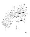
そこで、本実施形態の画像形成装置10では、画像光GLをハーフミラー31に対するS偏光成分及びP偏光成分を含む偏光状態の光として射出している。具体的に、本実施形態の画像形成装置10は、射出側偏光板11cの透過軸の方向を、ハーフミラー31(第1ハーフミラー31A及び第2ハーフミラー31B)に入射する画像光GLの偏光面の向きがハーフミラー31に対するS偏光面及びP偏光面の向きのいずれとも異なるように設定している。 Therefore, in the
図8は画像光GLの偏光面の向きを示す図である。なお、図8では、画像形成装置10から射出された画像光GLの偏光面の向きを示す。図8に示すように、ハーフミラー31に対するP偏光の偏光面Mp(以下、P偏光面Mpと称す場合もある)と、ハーフミラー31に対するS偏光の偏光面Ms(以下、S偏光面Msと称す場合もある)とは互いに直交している。 FIG. 8 is a diagram showing the direction of the polarization plane of the image light GL. FIG. 8 shows the direction of the polarization plane of the image light GL emitted from the
本実施形態の光学素子30では、第1ハーフミラー31AにおけるS偏光成分の反射率Rs1(0.3)と第2ハーフミラー31BにおけるP偏光成分の反射率Rp2(0.3)とが等しい。 In the
この光学素子30において、第1ハーフミラー31Aによる反射光(S偏光成分)の強度と第2ハーフミラー31Bによる反射光(P偏光成分)の強度とを等しくするには、画像光GLがP偏光成分とS偏光成分とを同じ割合で含んだ光としてハーフミラー31に入射すればよい。 In this
具体的に、P偏光成分とS偏光成分とを同じ割合で含む画像光GLを生成するには、画像光GLの偏光面がハーフミラー31に対するP偏光面MpとS偏光面Msとの間に位置していればよい。すなわち、図8に示すように、画像形成装置10において、射出側偏光板11cを透過した画像光GLの偏光面GMがP偏光面Mp又はS偏光面Msに対してなす角度θ1が45度となるように、射出側偏光板11cの透過軸の向きが設定されている。なお、射出側偏光板11cの透過軸T1の向きは、射出側偏光板11cを透過した画像光GLの偏光面GMの向きと同じである。 Specifically, in order to generate the image light GL including the P polarization component and the S polarization component at the same ratio, the polarization plane of the image light GL is between the P polarization plane Mp and the S polarization plane Ms with respect to the
射出側偏光板11cの透過軸T1の向きを調整する場合、射出側偏光板11cとともに液晶パネル11a及び入射側偏光板11bを光軸AXの周りに回転させるようにする。これにより、液晶パネル11aの配向方向と、入射側偏光板11bの透過軸と、射出側偏光板11cの透過軸との位置関係を保ったまま、ハーフミラー31に入射する画像光GLの偏光面の向きを調整することが可能となる。 When adjusting the direction of the transmission axis T1 of the exit-side
このような構成に基づき、本実施形態の画像形成装置10によれば、第1ハーフミラー31A及び第2ハーフミラー31Bに対して、ハーフミラー31に対するP偏光成分及びS偏光成分を同じ割合で含む偏光状態の画像光GLを入射させることができる。 Based on such a configuration, according to the
図9は、光学素子30の第1の作用を説明するための図である。
ここで、元の画像光GLに含まれるS偏光成分及びP偏光成分の強度をそれぞれ1とすると、図9に示すように、第1ハーフミラー31Aからの反射光の強度IAは、第1ハーフミラー31Aで反射したP偏光成分の強度Ip1とS偏光成分の強度Is1との和となり、IA=Ip1+Is1=0+0.3=0.3と表される。FIG. 9 is a diagram for explaining the first action of the
Here, assuming that the intensity of the S-polarized component and the P-polarized component included in the original image light GL is 1, the intensity IA of the reflected light from the
また、第2ハーフミラー31Bからの反射光の強度IBは、第1ハーフミラー31Aを透過した後、第2ハーフミラー31Bで反射したP偏光成分の強度Ip2とS偏光成分の強度Is2との和となり、IB=Ip2+Is2==1×0.3+0.7×0=0.3と表される。 The intensity IB of the reflected light from the
つまり、各ハーフミラー31A,31Bからの反射光の強度差dは、d=|IA−IB|=0となる。このように、本実施形態の光学素子30によれば、第1ハーフミラー31Aからの反射光の強度と第2ハーフミラー31Bからの反射光の強度とを等しくすることができる。よって、射出面32bから射出される反射光の強度プロファイルに差が生じないので、縞状のムラを視認され難くできる。したがって、観察者はムラの無い均一性の高い画像を視認することができる。 That is, the intensity difference d of the reflected light from the half mirrors 31A and 31B is d = | IA−IB | = 0. Thus, according to the
続いて、本実施形態の光学素子30の第2の作用および効果について説明する。まず、本実施形態の光学素子30の説明に先立ち、比較として従来の光学素子130について説明する。 Subsequently, the second action and effect of the
図10は、従来の光学素子130の第2の作用を説明するための図である。
図10に示すように、従来の光学素子130においては、複数のハーフミラー131の反射特性は、全てのハーフミラー131にわたって同一であった。ハーフミラー131に対するP偏光成分の反射率RpをRp=0(0%)とし、S偏光成分の反射率RsをRs=0.3(30%)とする。また、ハーフミラー131に対するP偏光成分の透過率TpをTp=1(100%)とし、S偏光成分の透過率TsをTs=0.7(70%)とする。FIG. 10 is a diagram for explaining a second action of the conventional
As shown in FIG. 10, in the conventional
ここで、外界光ELが光学素子130の入射面130aに垂直に入射する場合を考える。外界光ELが最初に入射するハーフミラー131を第1ハーフミラー131Aと称し、第1ハーフミラー131Aで反射した外界光ELが次に入射するハーフミラー131を第2ハーフミラー131Bと称する。第1ハーフミラー131Aを透過して観察者の眼に導かれる透過光EL1の強度をICとし、第1ハーフミラー131Aで反射した後に第2ハーフミラー131Bで再度反射して観察者の眼に導かれる反射光EL2の強度をIGとする。なお、外界光ELは無偏光であることから、ハーフミラー131に対するP偏光成分及びS偏光成分を含んでいる。 Here, consider a case where the external light EL is incident on the
元の外界光ELの強度を1としたとき、第1ハーフミラー131Aからの透過光EL1の強度ICは、第1ハーフミラー131Aを透過したP偏光成分の強度Ip1とS偏光成分の強度Is1との和となり、IC=Ip1+Is1=Tp+Ts=1+0.7=1.7と表される。 When the intensity of the original external light EL is 1, the intensity IC of the transmitted light EL1 from the
これに対し、第2ハーフミラー131Bからの反射光EL2の強度IGは、第1ハーフミラー131Aで反射した後、第2ハーフミラー131Bで反射したP偏光成分の強度Ip2とS偏光成分の強度Is2との和となり、IG=Ip2+Is2=Rp×Rp+Rs×Rs=0×0+0.3×0.3=0.09と表される。この場合、第1ハーフミラー131Aに隣り合う第2ハーフミラー131Bから反射光が射出されるため、外界像が二重に見える現象(ゴースト)が発生する。ここで、IG/ICの値をゴーストコントラストCと定義すると、C=0.09/1.7=0.053となる。 In contrast, the intensity IG of the reflected light EL2 from the
これに対し、本実施形態の光学素子30においては、上述したように、第1ハーフミラー31Aと第2ハーフミラー31Bとが交互に配置されている。また、例えば、第1ハーフミラー31Aにおいて、S偏光成分の反射率Rs1を0.3、S偏光成分の透過率Ts1を0.7、P偏光成分の反射率Rp1を0、P偏光成分の透過率Tp1を1とした。第2ハーフミラー31Bにおいて、S偏光成分の反射率Rs2を0、S偏光成分の透過率Ts2を1、P偏光成分の反射率Rp2を0.3、P偏光成分の透過率Tp2を0.7とした。 On the other hand, in the
図11は、本実施形態の光学素子30の第2の作用を説明するための図である。
図11に示すように、元の外界光ELの強度を1としたとき、第1ハーフミラー31Aからの透過光EL1の強度ICは、第1ハーフミラー31Aを透過したP偏光成分の強度Ip1とS偏光成分の強度Is1との和となり、IC=Ip1+Is1=Tp1+Ts1=1+0.7=1.7と表される。また、第2ハーフミラー31Bからの反射光の強度IGは、第1ハーフミラー31Aで反射した後、第2ハーフミラー31Bで反射したP偏光成分の強度Ip2とS偏光成分の強度Is2との和となり、IG=Ip2+Is2=Rp1×Rp2+Rs1×Rs2=0×0.3+0.3×0=0と表される。すなわち、第1ハーフミラー31Aで反射した後、第2ハーフミラー31Bで続けて反射された後に観察者の眼に導かれる光は存在しない。FIG. 11 is a diagram for explaining the second action of the
As shown in FIG. 11, when the intensity of the original external light EL is 1, the intensity IC of the transmitted light EL1 from the
このように、本実施形態の光学素子30においては、一つのハーフミラー31に入射した外界光ELの一部が反射して、隣り合うハーフミラー31から射出されることを抑制できるため、外界像のゴーストを見えにくくすることができる。 As described above, in the
(第1変形例)
上記第1実施形態の説明では、光学素子30として、ハーフミラー31(第1ハーフミラー31A及び第2ハーフミラー31B)におけるS偏光成分の反射率Rs1とP偏光成分の反射率Rp2とが等しい場合を例に挙げて説明したが、反射率Rs1及び反射率Rp2は異なっていても良い。(First modification)
In the description of the first embodiment, as the
例えば、光学素子30として、第1ハーフミラー31Aにおける反射率Rs1が第2ハーフミラー31Bにおける反射率Rp2より小さいものを用いても良い。この光学素子30を用いた場合において、第1ハーフミラー31Aによる反射光(S偏光成分)の強度と第2ハーフミラー31Bによる反射光(P偏光成分)の強度とを等しくするためには、P偏光成分よりもS偏光成分を多く含む画像光GLを生成すればよい。 For example, the
ここで、画像光GLの偏光面とハーフミラー31に対するP偏光面Mpとがなす角度をθ1(図8参照)とすると、画像光GLにおけるS偏光成分の光量とP偏光成分の光量との比はsin2θ1:cos2θ1となる。よって、光学素子30において、画像光GLの偏光面GMとP偏光面Mpとがなす角度θ1を45度よりも大きくするように、射出側偏光板11cの透過軸T1の向きを設定することで、P偏光成分よりもS偏光成分を相対的に多く含む画像光GLを生成できる。Here, if the angle formed by the polarization plane of the image light GL and the P polarization plane Mp with respect to the
この画像光GLによれば、相対的に反射率の低い第1ハーフミラー31Aに対するS偏光成分の光の入射量を増やしつつ、相対的に反射率の高い第2ハーフミラー31Bに対するP偏光成分の光の入射量を抑えることができる。したがって、第1ハーフミラー31Aによる反射光(S偏光成分)の強度と第2ハーフミラー31Bによる反射光(P偏光成分)の強度とを等しくできる。 According to this image light GL, while increasing the incident amount of light of the S-polarized component with respect to the
或いは、光学素子30として、第1ハーフミラー31Aにおける反射率Rs1が第2ハーフミラー31Bにおける反射率Rp2より大きいものを用いても良い。この光学素子30を用いた場合において、第1ハーフミラー31Aによる反射光(S偏光成分)の強度と第2ハーフミラー31Bによる反射光(P偏光成分)の強度とを等しくするためには、S偏光成分よりもP偏光成分を多く含む画像光GLを生成すればよい。 Alternatively, the
この場合、光学素子30において、画像光GLの偏光面とP偏光面Mpとがなす角度θ1を45度よりも小さくするように、射出側偏光板11cの透過軸T1の向きを設定することで、S偏光成分よりもP偏光成分を相対的に多く含む画像光GLを生成できる。 In this case, in the
この画像光GLによれば、相対的に反射率の高い第1ハーフミラー31Aに対するS偏光成分の光の入射量を減らしつつ、相対的に反射率の低い第2ハーフミラー31Bに対するP偏光成分の光の入射量を増やすことができる。したがって、第1ハーフミラー31Aによる反射光(S偏光成分)の強度と第2ハーフミラー31Bによる反射光(P偏光成分)の強度とを等しくできる。 According to this image light GL, the amount of incident light of the S-polarized component with respect to the
(第2実施形態)
続いて、第2実施形態に係る表示装置について説明する。本実施形態と第1実施形態との違いは、画像形成装置の構成であり、それ以外の構成は共通である。そのため、第1実施形態と共通の構成については同じ符号を付し、詳細な説明については省略する。(Second Embodiment)
Subsequently, a display device according to the second embodiment will be described. The difference between the present embodiment and the first embodiment is the configuration of the image forming apparatus, and the other configurations are the same. For this reason, the same reference numerals are assigned to configurations common to the first embodiment, and detailed description thereof is omitted.
図12は本実施形態の画像形成装置の構成を示す図である。
図12に示すように、本実施形態の画像形成装置110は、第1実施形態の画像形成装置10の構成に加えて、位相差板15をさらに備える点で異なる。なお、位相差板15の配置位置は、画像光GLの光路のうち射出側偏光板11cと光学素子30との間であればいずれでも構わない。FIG. 12 is a diagram showing the configuration of the image forming apparatus of this embodiment.
As shown in FIG. 12, the
本実施形態では、液晶表示装置11における射出側偏光板11cの外側に位相差板15を配置した。具体的に、射出側偏光板11cと位相差板15とは後述のように角度を精度良く調整する必要があるため、位相差板15を射出側偏光板11cの近傍に配置するのが望ましい。 In the present embodiment, the
ここで、第1実施形態の画像形成装置10では、画像光GLの偏光面を回転させるために射出側偏光板11cの向きを調整する場合を例に挙げたが、装置構成の都合上、射出側偏光板11cの向きを変更することが困難なこともあり得る。 Here, in the
これに対し、本実施形態の画像形成装置110は、位相差板15を用いることで画像光GLの偏光面の向きを調整するようにした。具体的に、位相差板15は画像光GLの波長に対する1/2波長板で構成されている。位相差板15の光学軸は、射出側偏光板11cの透過軸と交差する。なお、位相差板5の光学軸は、位相差板5の進相軸もしくは遅相軸のいずれであってもよい。 On the other hand, the
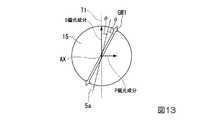
ここで、位相差板15による効果について説明する。図13は位相差板15を光軸AX方向から視た図である。図13に示すように、位相差板5の遅相軸5aと射出側偏光板11cの透過軸T1とのなす角度をθとすると、位相差板5から射出される画像光GLの偏光面GM1は、射出側偏光板11cを透過した直後の偏光面に対し2θだけ回転する。 Here, the effect of the
例えば、射出側偏光板11cの透過軸T1の方向がS偏光成分に対応している場合、位相差板15の遅相軸5aを透過軸T1に対して時計回りに22.5度傾けるように配置すると(θ=22.5度)、位相差板15から射出される画像光GLの偏光面GM1が45度回転する。すなわち、第1実施形態の画像形成装置10において、射出側偏光板11cをP偏光面Mpに対して45度傾けた場合(図8参照)と同じ効果を得ることができる。 For example, when the direction of the transmission axis T1 of the exit
したがって、本実施形態の画像形成装置110においても、第1実施形態の画像形成装置10と同様の効果を得ることができる。また、位相差板15を回転させることで画像光GLの偏光面を簡便且つ確実に回転させることができる。よって、液晶表示装置11側における光学軸の調整をする必要が無いので、画像形成装置210の組み立て性を向上させることができる。 Therefore, the
(第2変形例)
なお、上記第2実施形態の説明では、位相差板15として、1/2波長板を用いる場合について説明したが、本発明はこれに限定されない。(Second modification)
In the description of the second embodiment, the case where a half-wave plate is used as the
例えば、1/2波長板からなる位相差板15に代えて1/4波長板からなる位相差板を用いるようにしても良い。
以下、1/4波長板からなる位相差板115の効果について図14を参照しながら説明する。
例えば、射出側偏光板11cの透過軸T1がS偏光成分に対応している場合、位相差板115の遅相軸115aを図14に示すように透過軸T1に対して45度の角度をなすように傾けると、位相差板115から射出される画像光GLが円偏光に変換される。円偏光の画像光GLはP偏光成分とS偏光成分とを同じ割合で含んだ偏光状態の光となる。For example, instead of the
Hereinafter, the effect of the
For example, when the transmission axis T1 of the exit
したがって、本変形例のように位相差板115を用いる場合においても、第2実施形態の画像形成装置110と同様の効果を得ることができる。 Therefore, even when the
(第3変形例)
なお、上記第2実施形態及び第2変形例においては、ハーフミラー31(第1ハーフミラー31A及び第2ハーフミラー31B)におけるS偏光成分の反射率Rs1とP偏光成分の反射率Rp2とが等しい場合について説明したが、本発明はこれに限定されない。(Third Modification)
In the second embodiment and the second modification, the reflectance Rs1 of the S polarization component and the reflectance Rp2 of the P polarization component in the half mirror 31 (the
光学素子30として、第1ハーフミラー31Aにおける反射率Rs1と第2ハーフミラー31Bにおける反射率Rp2とが異なるものを用いても良い。
この光学素子30を用いた場合において、第1ハーフミラー31Aによる反射光(S偏光成分)の強度と第2ハーフミラー31Bによる反射光(P偏光成分)の強度とを等しくするには、相対的に反射率の低いハーフミラー31に対応する偏光成分の光の入射量を増やしつつ、相対的に反射率の高いハーフミラー31に対する偏光成分の光の入射量を抑えるように画像光GLの偏光状態を制御すれば良い。As the
In the case of using this
例えば、上記第2変形例において、図14に示した1/4波長板からなる位相差板115の遅相軸115aが射出側偏光板11cの透過軸T1に対してなす角度を45度以外の角度に調整すれば、画像光GLを楕円偏光に変換することができる。楕円偏光からなる画像光GLは、その楕円形状に応じてP偏光成分とS偏光成分とを所定の割合で含んだ偏光状態の光となる。 For example, in the second modified example, the angle formed by the
このように、第1ハーフミラー31Aの反射率Rs1と第2ハーフミラー31Bの反射率Rp2とが異なる場合であっても、位相差板115の角度を適宜調整することで、相対的に反射率の低いハーフミラー31に対応する偏光成分の光の入射量を増やしつつ、相対的に反射率の高いハーフミラー31に対する偏光成分の光の入射量を抑える画像光GLを生成することができる。
したがって、第1ハーフミラー31Aによる反射光(S偏光成分)の強度と第2ハーフミラー31Bによる反射光(P偏光成分)の強度とを等しくすることができる。Thus, even when the reflectance Rs1 of the
Therefore, the intensity of the reflected light (S-polarized component) by the
(第4変形例)
なお、上記実施形態及び変形例では、液晶パネル11aの光源としてバックライト11dを用いる場合について説明したが、本発明はこれに限定されない。(Fourth modification)
In addition, although the said embodiment and the modification demonstrated the case where the
図15は第4変形例に係る液晶表示装置111の概略構成を示す図である。
図15に示すように、本変形例の液晶表示装置111は、液晶パネル11aと、入射側偏光板11bと、射出側偏光板11cと、レーザー光源111dと、ビーム径拡大素子112と、ビーム整形素子113とを有している。FIG. 15 is a diagram showing a schematic configuration of a liquid
As shown in FIG. 15, the liquid
レーザー光源111dは例えば一つのレーザー素子から構成される。レーザー光源111dから射出されるレーザー光LAのビーム径は小さい。そのため、本変形例では、レーザー光LAのビーム径をビーム径拡大素子112によって拡大している。 The
ビーム径拡大素子112は、例えば、第1レンズ112aと第2レンズ112bとから構成される。レーザー光LAはビーム径拡大素子112を透過することで略液晶パネル11aの外形と同程度の大きさまでビーム径が拡大する。 The beam
ビーム径拡大素子112によりビーム径が拡大されたレーザー光LAは、ビーム整形素子113により放射角を拡げることで液晶パネル11aの外形に対応した形状に整形され、液晶パネル11aの画像形成領域の全体に入射する。これにより、画像光GLのサイズを大きくすることができるので、観察者の眼の位置が変化したとしても画像光GLが眼に入射し易くなる。そのため、観察者は視野に欠けの生じない良好な画像を視認することができる。 The laser beam LA whose beam diameter has been expanded by the beam
なお、ビーム整形素子113としては、例えば、複数のマイクロレンズを用いた構成やホログラム等の微細形状からなる構成のものを例示できる。 Examples of the
(第3実施形態)
続いて、第3実施形態に係る表示装置について説明する。本実施形態と第1実施形態との違いは、画像形成装置の構成であり、それ以外の構成は共通である。そのため、第1実施形態と共通の構成については同じ符号を付し、詳細な説明については省略する。(Third embodiment)
Subsequently, a display device according to a third embodiment will be described. The difference between the present embodiment and the first embodiment is the configuration of the image forming apparatus, and the other configurations are the same. For this reason, the same reference numerals are assigned to configurations common to the first embodiment, and detailed description thereof is omitted.
図16は本実施形態の画像形成装置310の構成を示す図である。
図16に示すように、本実施形態の画像形成装置310は、レーザー光源51と、ピックアップ光学系52と、導光光学系53と、マイクロミラー型光変調装置54とを備えている。FIG. 16 is a diagram showing a configuration of the
As shown in FIG. 16, the
本実施形態において、レーザー光源51は、赤色光LR、緑色光LG、青色光LBを時分割で射出する。ピックアップ光学系52は、レーザー光源51から射出される光を平行化し、導光光学系53へと導く。 In the present embodiment, the
導光光学系53は、反射ミラーから構成されている。導光光学系53は、レーザー光源51からの光を反射することでマイクロミラー型光変調装置54に時分割で入射させる。 The light guide
マイクロミラー型光変調装置54として、例えばDMD(Digital Micromirror Device)が用いられる。DMDは、複数のマイクロミラー(可動反射素子)がマトリクス状に配列されたものである。DMDは、複数のマイクロミラーの傾き方向を切換えることにより、光の反射方向を、導光装置20に入射する方向と導光装置20に入射しない方向との間で切り替える。 For example, a DMD (Digital Micromirror Device) is used as the
本実施形態のレーザー光源51は、赤色光LRを射出する第1レーザー素子51R、緑色光LGを射出する第2レーザー素子51G、および青色光LBを射出する第3レーザー素子51Bを有する。これら第1〜第3レーザー素子51R,51G,51Bは、不図示の実装基板(不図示)に実装されている。 The
このような構成に基づき、マイクロミラー型光変調装置54は、レーザー光源51から射出される赤色光LR、緑色光LG、および青色光LBを順次変調し、赤色画像光Lr、緑色画像光Lg、および青色画像光Lbを生成する。 Based on such a configuration, the micromirror
ところで、レーザー光源51から射出される赤色光LR、緑色光LG及び青色光LBは、直線偏光である。そのため、上記実施形態と同様に、赤色光LR、緑色光LG及び青色光LBの偏光面をハーフミラー31に対するP偏光面とS偏光面との間に位置させる必要がある。 Incidentally, the red light LR, the green light LG, and the blue light LB emitted from the
ここで、赤色光LR、緑色光LG及び青色光LBの偏光面の向きは、第1〜第3レーザー素子51R,51G,51Bの射出面の向き、すなわち、第1〜第3レーザー素子51R,51G,51Bにおける実装基板に対する取付方向で決まる。 Here, the directions of the polarization planes of the red light LR, the green light LG, and the blue light LB are the directions of the exit surfaces of the first to
本実施形態においても、上記実施形態と同様、第1ハーフミラー31AにおけるS偏光成分の反射率Rs1と第2ハーフミラー31BにおけるP偏光成分の反射率Rp2とが等しいものとする。 Also in the present embodiment, the reflectance Rs1 of the S-polarized component in the
例えば、本実施形態の画像形成装置310において、第1〜第3レーザー素子51R,51G,51Bの向きは、赤色画像光Lr、緑色画像光Lg、および青色画像光Lbの偏光面(偏光方向)がxz平面に対して45度の角度をなすように、設定される。 For example, in the
このようにすれば、第1ハーフミラー31A及び第2ハーフミラー31Bに対するP偏光成分及びS偏光成分を同じ割合で含む赤色画像光Lr、緑色画像光Lg、および青色画像光Lbをそれぞれ生成することができる。 In this way, the red image light Lr, the green image light Lg, and the blue image light Lb containing the P-polarized component and the S-polarized component for the
上記説明では、第1〜第3レーザー素子51R,51G,51Bの取り付け方向によって赤色画像光Lr、緑色画像光Lg、および青色画像光Lbの偏光面(偏光方向)を回転させる場合を例に挙げたが、位相差板(1/2波長板又は1/4波長板)を用いて偏光面を回転させるようにしても良い。位相差板はレーザー光源51とピックアップ光学系52との間、より望ましくはレーザー光源51の近傍に配置すればよい。 In the above description, the case where the polarization planes (polarization directions) of the red image light Lr, the green image light Lg, and the blue image light Lb are rotated according to the mounting directions of the first to
本実施形態においても、上記第4変形例のビーム径拡大素子112及びビーム整形素子113を用いることで赤色光LR、緑色光LG及び青色光LBのビーム径を拡大するとともに放射角を制御するようにしても構わない。 Also in the present embodiment, the beam diameter of the red light LR, the green light LG, and the blue light LB is enlarged and the radiation angle is controlled by using the beam
(第4実施形態)
続いて、第4実施形態に係る表示装置について説明する。本実施形態と第1実施形態との違いは、画像形成装置の構成であり、それ以外の構成は共通である。そのため、第1実施形態と共通の構成については同じ符号を付し、詳細な説明については省略する。(Fourth embodiment)
Subsequently, a display device according to a fourth embodiment will be described. The difference between the present embodiment and the first embodiment is the configuration of the image forming apparatus, and the other configurations are the same. For this reason, the same reference numerals are assigned to configurations common to the first embodiment, and detailed description thereof is omitted.
本実施形態の表示装置は、シースルー方式の網膜走査型表示装置である。図17は本実施形態の表示装置400の概略構成を示す図である。 The display device of this embodiment is a see-through retinal scanning display device. FIG. 17 is a diagram showing a schematic configuration of the
図17に示すように、本実施形態の表示装置400は、画像形成装置410と、導光装置20とを有する。 As illustrated in FIG. 17, the
画像形成装置410は、画像を表示するための画像光を射出するレーザー光源411と、レーザー光源411から射出された画像光を走査する走査ミラー412を有する走査光学系413と、走査光学系413により走査された画像光を観察者の眼EYに入射させる導光系414と、光線分割素子415とを有している。本実施形態において、光線分割素子415は特許請求の範囲の「光線束拡大素子」に相当する。 The
本実施形態において、レーザー光源411は、赤色画像光Lr、緑色画像光Lg及び青色画像光Lbをそれぞれ出射する第1〜第3レーザー素子411R,411G,411Bを有する。これら第1〜第3レーザー素子411R,411G,411Bは、不図示の実装基板に実装されている。走査光学系413は、例えば、MEMS技術により形成したマイクロミラーデバイスによって実現可能である。
以下、赤色画像光Lr、緑色画像光Lg及び青色画像光Lbを総称して画像光L1と称すことにする。In the present embodiment, the laser light source 411 includes first to third laser elements 411R, 411G, and 411B that emit red image light Lr, green image light Lg, and blue image light Lb, respectively. These first to third laser elements 411R, 411G, and 411B are mounted on a mounting board (not shown). The scanning
Hereinafter, the red image light Lr, the green image light Lg, and the blue image light Lb are collectively referred to as image light L1.
光線分割素子415は、走査光学系413から射出された画像光L1の光線を分割することで観察者に画像を見易くさせるためのものである。図18は光線分割素子415の構成を模式的に示す断面図、および光線分割素子415を通過する光の光線図である。図19は、光線分割素子415における光の偏光方向と回折機能との関係を示す説明図である。 The
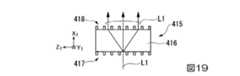
図18に示すように、本実施形態の光線分割素子415は、透光性基板416と、該透光性基板416の第1面416aに設けられた第1回折格子417と、透光性基板416の第2面416bに設けられた第2回折格子418とを備える。 As shown in FIG. 18, the light
以下、図17乃至19において、別のX1Y1Z1座標系を合わせて用いることで説明する。X1方向は透光性基板416における一対の面(第1面416a及び第2面416b)の法線方向に相当し、Z1方向は鉛直方向に相当し、Y1方向はX1方向及びZ1方向にそれぞれ直交する方向に相当する。なお、図17に示すように、XYZ座標系のX方向及びY方向は、X1Y1Z1座標系におけるX1軸及びY1軸をそれぞれZ1軸の周りに半時計回りに回転させた方向であり、XYZ座標系のZ方向とX1Y1Z1座標系におけるZ1方向とは一致している。Hereinafter, in FIG. 17 through 19 will be described by using together differentX1Y 1Z 1 coordinate system. X1 direction corresponds to the normal direction of the pair of surfaces in the translucent substrate 416 (
第1回折格子417は、Z1方向に沿って直線状に延在する複数の凸部417aからなる格子パターンを有する。第2回折格子418は、Z1方向に沿って直線状に延在する複数の凸部418aからなる格子パターンを有する。なお、第1回折格子417及び第2回折格子418は同一の格子周期を有する。The
ここで、第1回折格子417及び第2回折格子418は入射する偏光の振動方向によって回折効率が異なる。具体的に、第1回折格子417及び第2回折格子418に対して、画像光L1がZ1方向に振動するTM光として入射した場合、第1回折格子417及び第2回折格子418による光束径の拡大機能(回折機能)が十分に得られない。Here, the
これに対し、本実施形態において、レーザー光源411(第1〜第3レーザー素子411R,411G,411B)から射出された光は、光線分割素子415に入射する際にY1方向(凸部417a,418aの延伸方向)に振動する偏光となっている。すなわち、レーザー光源411から射出された画像光L1は、Y1方向に直線状に延在する凸部417a,418aからなる格子パターンを備えた第1回折格子417及び第2回折格子418に対してTE光として入射するようになる。よって、画像光L1は、図19に示すように、第1回折格子417及び第2回折格子418に回折されることでZ1方向における光束径が良好に拡大される。
なお、第1回折格子117及び第2回折格子118の構成は上記に限定されない。例えば、複数の凸部117a及び複数の凸部118aの間を屈折率の異なる部材、或いは金属線を埋め込んだ構成としても良い。In contrast, in the present embodiment, the laser light source 411 (first to third laser element 411R, 411G, 411B) light emitted from,Y 1 direction when entering the beam splitter 415 (
The configurations of the first diffraction grating 117 and the second diffraction grating 118 are not limited to the above. For example, a configuration in which a member having a different refractive index or a metal wire is embedded between the plurality of protrusions 117a and the plurality of protrusions 118a may be employed.
本実施形態によれば、光線分割素子415に対する画像光L1の入射方向を調整することで光線分割素子415による光束径の拡大機能を良好に発揮させることができる。 According to the present embodiment, by adjusting the incident direction of the image light L1 with respect to the light
また、光線分割素子415により光束径が拡大された画像光L1は、Z1方向に沿って振動する偏光である。すなわち、画像光L1は、X1Y1Z1座標系におけるZ1Y1平面に沿って振動する偏光であると換言することもできる。このようなZ1Y1平面に沿って振動する偏光は、ハーフミラー31の反射面31rに対するP偏光である。Further, the image light L1 of the light flux diameter is expanded by the
このように光線分割素子415により光束径が拡大された画像光L1は直線偏光(P偏光)となる。そのため、上記実施形態と同様に、画像光L1の偏光面は、ハーフミラー31に対するP偏光面とS偏光面との間に位置している必要がある。 Thus, the image light L1 whose beam diameter is enlarged by the
画像光L1の偏光面の向きは、例えば、第1〜第3レーザー素子51R,51G,51Bにおける実装基板(不図示)に対する取付向きによって調整可能である。 The direction of the polarization plane of the image light L1 can be adjusted by, for example, the mounting direction of the first to
本実施形態においても、上記実施形態と同様、第1ハーフミラー31AにおけるS偏光成分の反射率Rs1と第2ハーフミラー31BにおけるP偏光成分の反射率Rp2とが等しいものとする。 Also in the present embodiment, the reflectance Rs1 of the S-polarized component in the
例えば、本実施形態の画像形成装置410において、第1〜第3レーザー素子411R,411G,411Bの向きは、画像光L1の偏光面(偏光方向)がハーフミラー31に対するP偏光面Mp(図8参照)に対して45度の角度をなすように、設定される。このようにすれば、第1ハーフミラー31A及び第2ハーフミラー31Bに対するP偏光成分及びS偏光成分を同じ割合で含んだ画像光L1を生成することができる。 For example, in the
本実施形態においても、第1〜第3レーザー素子51R,51G,51Bの取付位置の調整に代えて、光線分割素子415の後段に位相差板(1/2波長板又は1/4波長板)を配置することで偏光面を回転させるようにしても良い。このようにすれば、位相差板の回転角を調整することで画像光L1における偏光状態(P偏光成分及びS偏光成分の比率)を所定の状態に変化させることができる。 Also in this embodiment, instead of adjusting the mounting positions of the first to
(第5変形例)
第4実施形態の光線分割素子415の構成は限定されない。図20は第5変形例に係る光線分割素子の変形例に係る構成を示す図である。なお、第4実施形態と共通の構成については同じ符号を付し、説明については省略する。(5th modification)
The configuration of the light
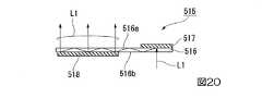
図20に示す光線分割素子515は、導光板516と、光入射部517と、光射出部518とを有する。導光板516は平行平板から構成され、本実施形態において、導光板516は例えばガラス基板から構成されている。 A light
光入射部517は、導光板516における上面516aの一端側に設けられ、導光系414(図17参照)を介して導光板516の下面516bから入射した画像光L1を導光板516内に入射させる。光入射部517は、該光入射部517に入射する画像光L1を導光板516の長辺方向に回折する機能を有している。本実施形態において、光入射部517は、ホログラム回折素子から構成されている。 The
光射出部518は、導光板516における下面516bの他端側に設けられ、光入射部517により導光板516内に取り込まれた画像光L1を回折して導光板516の上面516aから射出する。本実施形態において、光射出部518は、ホログラム回折素子から構成されている。
画像光L1は光射出部518で回折されることで複数(図20では3つ)に分割される。よって、本変形例に係る光線分割素子515においても、第4実施形態の光線分割素子415と同様に、画像光L1における光束径を拡大することができる。The
The image light L1 is diffracted by the
(第6変形例)
図21は第6変形例に係る光線分割素子の変形例に係る構成を示す図である。なお、第4実施形態と共通の構成については同じ符号を付し、説明については省略する。
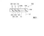
図21に示す光線分割素子615は、透光性部材610と、第1のハーフミラー611及び第2のハーフミラー612と、光射出用ミラー613と、光入射用ミラー614とを有する。なお、第1のハーフミラー611と、第2のハーフミラー612と、光射出用ミラー613と、光入射用ミラー614とは、いずれも透光性部材610内に設けられている。(Sixth Modification)
FIG. 21 is a diagram illustrating a configuration according to a modification of the light beam splitting element according to the sixth modification. In addition, the same code | symbol is attached | subjected about the same structure as 4th Embodiment, and description is abbreviate | omitted.
A
本実施形態において、透光性部材610は例えばガラス基板から構成されている。光入射用ミラー614は、導光系414(図17参照)を介して透光性部材610の下面610bから入射した画像光L1を反射させるように設けられる。 In the present embodiment, the
第1のハーフミラー611及び第2のハーフミラー612は、光入射用ミラー614に近い方から順番に設けられている。 The
第1のハーフミラー611は、画像光L1の一部である画像光L1aを反射して透光性部材610の上面610aから射出させるとともに画像光L1の残りの一部である画像光L1bを透過して第2のハーフミラー612に入射させる。 The
第2のハーフミラー612は、第1のハーフミラー611を透過した画像光L1bの一部である画像光L2aを反射して透光性部材610の上面610aから射出させるとともに画像光L1bの残りの一部である画像光GL2bを透過して光射出用ミラー613に入射させる。光射出用ミラー613は第2のハーフミラー612を透過した画像光L2bを反射して透光性部材610の上面610aから射出させる。 The
第1のハーフミラー611及び第2のハーフミラー612の光学特性(反射率及び透過率)は、透光性部材610の上面610aから射出される画像光L1a、L2a、L2bの光量がほぼ同等となるように設定される。 Regarding the optical characteristics (reflectance and transmittance) of the
画像光L1は透光性部材610内に設けられた第1のハーフミラー611及び第2のハーフミラー612を透過することで複数(図21では3つ)に分割される。よって、本変形例に係る光線分割素子615においても、第4実施形態の光線分割素子415と同様に、画像光L1における光束径を拡大することができる。 The image light L1 is divided into a plurality (three in FIG. 21) by passing through the
(第5実施形態)
続いて、本発明の第5実施形態として、照明装置の一例について説明する。図22は照明装置200の概略構成を示す図である。図22に示すように、本実施形態の照明装置200は、照明光を射出する光源装置201と、導光装置202と、を備えている。(Fifth embodiment)
Then, an example of an illuminating device is demonstrated as 5th Embodiment of this invention. FIG. 22 is a diagram illustrating a schematic configuration of the
光源装置201は、白色の照明光SLを射出する光源201aと、照明光SLが入射する位相差板201bと、投射レンズ201cとを有する。光源201aとしては、例えば、レーザー素子等の直線偏光からなる照明光SLを射出するものを用いた。位相差板201bとしては、例えば、1/2波長板を用いた。投射レンズ210cは位相差板201bを透過した照明光SLを平行化して導光装置202に入射させる。 The light source device 201 includes a light source 201a that emits white illumination light SL, a phase difference plate 201b on which the illumination light SL is incident, and a
本実施形態の光源装置201では、位相差板201bを用いて照明光SLの偏光面の向きを調整することで、照明光SLをハーフミラー31に対するS偏光成分及びP偏光成分を含む偏光状態の光として射出させるようにしている。 In the light source device 201 of this embodiment, the polarization state of the illumination light SL including the S polarization component and the P polarization component with respect to the
例えば、光源201aから射出された直後の照明光SLの偏光面がハーフミラー31に対するS偏光に相当する場合、位相差板201bの遅相軸を22.5度傾けることで位相差板201bから射出される照明光SLの偏光面を45度回転させることができる。これにより、第1実施形態の画像形成装置10において、射出側偏光板11cをxz平面に対して45度傾けたときと同様の効果を得ることができる。 For example, when the polarization plane of the illumination light SL immediately after being emitted from the light source 201a corresponds to S-polarized light with respect to the
したがって、本実施形態の照明装置200によれば、第1ハーフミラー31Aからの反射光の強度と第2ハーフミラー31Bからの反射光の強度とを等しくすることができる。よって、射出面32bから射出される照明光SLの強度プロファイルに差が生じないので、縞状のムラを視認され難くできる。したがって、観察者はムラの無い均一性の高い照明光SLを視認できる。 Therefore, according to the
なお、本発明の技術範囲は上記実施形態に限定されるものではなく、本発明の趣旨を逸脱しない範囲において種々の変更を加えることが可能である。 The technical scope of the present invention is not limited to the above embodiment, and various modifications can be made without departing from the spirit of the present invention.
例えば、第1ハーフミラー31Aにおける反射率Rs1と第2ハーフミラー31Bにおける反射率Rp2とが等しい光学素子30を用いる場合、画像光GLの偏光状態は非偏光であっても良い。すなわち、反射率Rs1と反射率Rp2とが等しい光学素子30を用いる場合においては、画像光を非偏光に戻した状態で光学素子30に入射させるようにしても良い。画像光GLを非偏光に戻す素子としては、例えば、水晶を用いた水晶偏光解消素子を例示することができる。 For example, when the
その他、光学素子および表示装置に構成する各構成要素の数、形状、材料等の各部の具体的な構成については、上記実施形態及び変形例に限ることなく、適宜変更が可能である。 In addition, the specific configuration of each part such as the number, shape, material, and the like of each constituent element included in the optical element and the display device can be appropriately changed without being limited to the above-described embodiments and modifications.
また、上記実施形態では、表示装置100,400として、右眼及び左眼の双方に対応して一組ずつ画像形成装置及び導光装置を設ける構成としているが、右眼又は左眼のいずれか一方に対してのみ画像形成装置と導光装置とを設け、画像を片眼視する構成、すなわち、単眼用の表示装置に適用してもよい。 Further, in the above-described embodiment, the
また、以上説明した実施形態では、表示装置がヘッドマウントディスプレイであるとして具体的な説明を行ったが、本発明の表示装置は、ヘッドアップディスプレイ、双眼鏡型のハンドヘルドディスプレイ等に適用することもできる。 In the embodiment described above, the display device is specifically described as a head-mounted display. However, the display device of the present invention can be applied to a head-up display, a binocular-type handheld display, and the like. .
5…位相差板、10,110,210,310,410…画像形成装置、11a…液晶パネル、11c…射出側偏光板、15…位相差板、21…入射部、22…導光体、23…射出部、31,131…ハーフミラー、31A,131A…第1ハーフミラー、31B,131B…第2ハーフミラー、51,411…レーザー光源、100,400…表示装置、115…位相差板、200…照明装置、201…光源装置、201b…位相差板、415…光線分割素子(光線束拡大素子)、417…第1回折格子、417a…凸部、418…第2回折格子、418a…凸部、GL0,GL1,GL2,GL2b,GL…画像光、GM1,GM…偏光面、GR1,GR2…画像光、L1…画像光、LA…レーザー光、SL…照明光。 DESCRIPTION OF SYMBOLS 5 ...
Claims (11)
Translated fromJapanese前記画像形成装置から射出された前記画像光を導光する導光体と、
前記画像光を前記導光体に入射させる入射部と、
前記画像光を前記導光体から射出させる射出部と、を備え、
前記射出部は、間隔をおいて互いに平行となるように設けられ、前記画像光および外界光の一部を反射させ、前記画像光および前記外界光の他の一部を透過させる複数のハーフミラーを有し、
前記複数のハーフミラーは、前記ハーフミラーに対するS偏光成分の反射率が前記ハーフミラーに対するP偏光成分の反射率に比べて相対的に高い複数の第1ハーフミラーと、前記P偏光成分の反射率が前記S偏光成分の反射率に比べて相対的に高い複数の第2ハーフミラーとを含み、
前記第1ハーフミラーと前記第2ハーフミラーとは、前記複数のハーフミラーの配列方向において交互に配置され、
前記画像形成装置は、前記画像光を前記ハーフミラーに対するS偏光成分及びP偏光成分を含む偏光状態の光として射出する
ことを特徴とする表示装置。An image forming apparatus for emitting image light;
A light guide for guiding the image light emitted from the image forming apparatus;
An incident portion for causing the image light to enter the light guide;
An emission unit for emitting the image light from the light guide,
A plurality of half mirrors provided so as to be parallel to each other at an interval and reflecting a part of the image light and the external light and transmitting the other part of the image light and the external light; Have
The plurality of half mirrors include a plurality of first half mirrors in which the reflectance of the S polarization component relative to the half mirror is relatively higher than the reflectance of the P polarization component relative to the half mirror, and the reflectance of the P polarization component. A plurality of second half mirrors that are relatively higher than the reflectance of the S-polarized component,
The first half mirror and the second half mirror are alternately arranged in the arrangement direction of the plurality of half mirrors,
The image forming apparatus emits the image light as light in a polarization state including an S polarization component and a P polarization component for the half mirror.
前記射出側偏光板の透過軸の方向は、前記ハーフミラーに入射する前記画像光の偏光面の向きが前記ハーフミラーに対するS偏光面及びP偏光面の向きのいずれとも異なるように設定されている
ことを特徴とする請求項1に記載の表示装置。The image forming apparatus includes a panel unit that emits the image light, and an emission-side polarizing plate provided on a light emission side of the panel unit,
The direction of the transmission axis of the exit side polarizing plate is set so that the orientation of the polarization plane of the image light incident on the half mirror is different from the orientation of the S polarization plane and the P polarization plane with respect to the half mirror. The display device according to claim 1.
ことを特徴とする請求項1に記載の表示装置。The image forming apparatus includes: a panel unit that emits the image light; an emission-side polarizing plate that is provided on a light-emitting side of the panel unit; and a first phase difference in which light emitted from the emission-side polarizing plate is incident The display device according to claim 1, further comprising: a plate.
ことを特徴とする請求項3に記載の表示装置。The display device according to claim 3, wherein the first retardation plate is a half-wave plate.
ことを特徴とする請求項3に記載の表示装置。The display device according to claim 3, wherein the first retardation plate is a ¼ wavelength plate.
前記レーザー光源は、前記ハーフミラーに入射する前記画像光の偏光面の向きが前記ハーフミラーに対するS偏光面及びP偏光面の向きと異なるように、設置されている
ことを特徴とする請求項1に記載の表示装置。The image forming apparatus includes a laser light source that emits linearly polarized light as the image light,
2. The laser light source is installed so that a direction of a polarization plane of the image light incident on the half mirror is different from a direction of an S polarization plane and a P polarization plane with respect to the half mirror. The display device described in 1.
ことを特徴とする請求項1に記載の表示装置。The image forming apparatus includes: a laser light source that emits linearly polarized light as the image light; and a second retardation plate on which the image light emitted from the laser light source is incident. The display device described in 1.
ことを特徴とする請求項7に記載の表示装置。The display device according to claim 7, wherein the second retardation plate is a half-wave plate.
ことを特徴とする請求項7に記載の表示装置。The display device according to claim 7, wherein the second retardation plate is a ¼ wavelength plate.
前記光線束拡大素子は、一方向に沿って延伸する複数の凸部からなる格子パターンを含む回折素子から構成されており、
前記画像光は、前記複数の凸部の延伸方向に沿って振動する光として前記光線束拡大素子に入射する
ことを特徴とする請求項6乃至8のいずれか一項に記載の表示装置。The image forming apparatus includes a light beam expanding element that expands a light beam diameter of the image light.
The light flux expanding element is composed of a diffractive element including a grating pattern composed of a plurality of convex portions extending along one direction,
The display device according to claim 6, wherein the image light is incident on the light beam expanding element as light that vibrates along an extending direction of the plurality of convex portions.
前記光源装置から射出された前記照明光を導光する導光体と、
前記照明光を前記導光体に入射させる入射部と、
前記照明光を前記導光体から射出させる射出部と、を備え、
前記射出部は、間隔をおいて互いに平行となるように設けられ、前記照明光および外界光の一部を反射させ、前記照明光および前記外界光の他の一部を透過させる複数のハーフミラーを有し、
前記複数のハーフミラーは、前記ハーフミラーに対するS偏光成分の反射率が前記ハーフミラーに対するP偏光成分の反射率に比べて相対的に高い複数の第1ハーフミラーと、前記P偏光成分の反射率が前記S偏光成分の反射率に比べて相対的に高い複数の第2ハーフミラーとからなり、
前記第1ハーフミラーと前記第2ハーフミラーとは、前記複数のハーフミラーの配列方向において交互に配置され、
前記光源装置は、前記照明光を前記ハーフミラーに対するS偏光成分及びP偏光成分を含む偏光状態の光として射出するように構成される
ことを特徴とする照明装置。A light source device for emitting illumination light;
A light guide for guiding the illumination light emitted from the light source device;
An incident portion for causing the illumination light to enter the light guide;
An emission part for emitting the illumination light from the light guide, and
A plurality of half mirrors provided so as to be parallel to each other at an interval and reflecting a part of the illumination light and the external light and transmitting the other part of the illumination light and the external light; Have
The plurality of half mirrors include a plurality of first half mirrors in which the reflectance of the S polarization component relative to the half mirror is relatively higher than the reflectance of the P polarization component relative to the half mirror, and the reflectance of the P polarization component. Comprises a plurality of second half mirrors that are relatively higher than the reflectance of the S-polarized component,
The first half mirror and the second half mirror are alternately arranged in the arrangement direction of the plurality of half mirrors,
The light source device is configured to emit the illumination light as light in a polarization state including an S-polarized component and a P-polarized component with respect to the half mirror.
Priority Applications (2)
| Application Number | Priority Date | Filing Date | Title |
|---|---|---|---|
| JP2017108816AJP2018205448A (en) | 2017-05-31 | 2017-05-31 | Display device and lighting device |
| US15/988,199US10732461B2 (en) | 2017-05-31 | 2018-05-24 | Display device and illumination device |
Applications Claiming Priority (1)
| Application Number | Priority Date | Filing Date | Title |
|---|---|---|---|
| JP2017108816AJP2018205448A (en) | 2017-05-31 | 2017-05-31 | Display device and lighting device |
Publications (1)
| Publication Number | Publication Date |
|---|---|
| JP2018205448Atrue JP2018205448A (en) | 2018-12-27 |
Family
ID=64459683
Family Applications (1)
| Application Number | Title | Priority Date | Filing Date |
|---|---|---|---|
| JP2017108816APendingJP2018205448A (en) | 2017-05-31 | 2017-05-31 | Display device and lighting device |
Country Status (2)
| Country | Link |
|---|---|
| US (1) | US10732461B2 (en) |
| JP (1) | JP2018205448A (en) |
Cited By (4)
| Publication number | Priority date | Publication date | Assignee | Title |
|---|---|---|---|---|
| US11086127B2 (en) | 2018-01-12 | 2021-08-10 | Colorlink Japan, Ltd. | Optical apparatus |
| CN113574442A (en)* | 2019-03-08 | 2021-10-29 | 图茨技术股份有限公司 | Optical system for generating virtual image and intelligent glasses |
| JP2023504611A (en)* | 2019-12-05 | 2023-02-06 | ルーマス リミテッド | Light-directing optics with complementary coated partial reflectors and light-directing optics with reduced light scattering |
| US11619816B2 (en)* | 2019-08-28 | 2023-04-04 | Seiko Epson Corporation | Head-mounted display |
Families Citing this family (16)
| Publication number | Priority date | Publication date | Assignee | Title |
|---|---|---|---|---|
| JP2019045858A (en)* | 2017-09-06 | 2019-03-22 | 矢崎総業株式会社 | Backlight unit and head-up display device |
| JP6663890B2 (en)* | 2017-09-06 | 2020-03-13 | 矢崎総業株式会社 | Backlight unit and head-up display device |
| US10551544B2 (en) | 2018-01-21 | 2020-02-04 | Lumus Ltd. | Light-guide optical element with multiple-axis internal aperture expansion |
| CN116184666A (en) | 2018-09-09 | 2023-05-30 | 鲁姆斯有限公司 | Optical system comprising a light-guiding optical element with two-dimensional expansion |
| CN109188700B (en)* | 2018-10-30 | 2021-05-11 | 京东方科技集团股份有限公司 | Optical display system and AR/VR display device |
| KR102099785B1 (en)* | 2018-11-06 | 2020-04-10 | 주식회사 레티널 | Optical device for augmented reality |
| MX2021008808A (en) | 2019-01-24 | 2021-08-24 | Lumus Ltd | Optical systems including loe with three stage expansion. |
| AU2020300121B2 (en) | 2019-07-04 | 2024-06-13 | Lumus Ltd. | Image waveguide with symmetric beam multiplication |
| US12111479B2 (en) | 2019-09-16 | 2024-10-08 | Lumus Ltd. | Image display system with beam multiplication |
| AU2021279462B2 (en) | 2020-05-24 | 2023-06-08 | Lumus Ltd. | Method of fabrication of compound light-guide optical elements |
| CN115176190B (en) | 2020-05-24 | 2024-07-09 | 鲁姆斯有限公司 | Composite light guide optical element |
| AU2021331833A1 (en) | 2020-08-23 | 2023-03-09 | Lumus Ltd. | Optical system for two-dimensional expansion of an image reducing glints and ghosts from the waveguide |
| JP2022039127A (en)* | 2020-08-28 | 2022-03-10 | 株式会社日立エルジーデータストレージ | Head-mounted display |
| FR3121760B1 (en)* | 2021-04-12 | 2023-12-29 | Commissariat Energie Atomique | REFLECTOR DEVICE INTENDED TO EMIT A PLURALITY OF REFLECTED BEAMS FROM A SINGLE MAIN LIGHT BEAM |
| KR20240046489A (en) | 2021-08-23 | 2024-04-09 | 루머스 리미티드 | Method for manufacturing composite light guiding optical elements with embedded coupling-in reflector |
| JP2024090193A (en)* | 2022-12-22 | 2024-07-04 | 株式会社ジャパンディスプレイ | Liquid crystal display device and head mounted display |
Family Cites Families (15)
| Publication number | Priority date | Publication date | Assignee | Title |
|---|---|---|---|---|
| JP4605152B2 (en) | 2004-03-12 | 2011-01-05 | 株式会社ニコン | Image display optical system and image display apparatus |
| JP4609160B2 (en) | 2004-05-17 | 2011-01-12 | 株式会社ニコン | Optical element, combiner optical system, and information display device |
| EP1748305A4 (en) | 2004-05-17 | 2009-01-14 | Nikon Corp | Optical element, combiner optical system, and image display unit |
| IL166799A (en)* | 2005-02-10 | 2014-09-30 | Lumus Ltd | Substrate-guided optical device utilizing beam splitters |
| US8643948B2 (en)* | 2007-04-22 | 2014-02-04 | Lumus Ltd. | Collimating optical device and system |
| US7589901B2 (en)* | 2007-07-10 | 2009-09-15 | Microvision, Inc. | Substrate-guided relays for use with scanned beam light sources |
| JP4395802B2 (en)* | 2007-11-29 | 2010-01-13 | ソニー株式会社 | Image display device |
| JP2012008356A (en) | 2010-06-25 | 2012-01-12 | Sony Corp | Optical element, image display apparatus and head-mounted display |
| JP2017003845A (en) | 2015-06-12 | 2017-01-05 | セイコーエプソン株式会社 | Light guide device and virtual image display device |
| KR20170030594A (en) | 2014-08-18 | 2017-03-17 | 세이코 엡슨 가부시키가이샤 | Light guide device and virtual image display apparatus |
| RU2579804C1 (en)* | 2014-09-16 | 2016-04-10 | Самсунг Электроникс Ко., Лтд. | Optical device for generating augmented reality images |
| JP6417589B2 (en)* | 2014-10-29 | 2018-11-07 | セイコーエプソン株式会社 | OPTICAL ELEMENT, ELECTRO-OPTICAL DEVICE, WEARING TYPE DISPLAY DEVICE, AND OPTICAL ELEMENT MANUFACTURING METHOD |
| CN104360484B (en)* | 2014-12-02 | 2017-03-08 | 京东方科技集团股份有限公司 | A kind of light wave medium, glasses and its imaging method |
| US9897811B2 (en)* | 2016-04-07 | 2018-02-20 | Google Llc | Curved eyepiece with color correction for head wearable display |
| JP2018049106A (en)* | 2016-09-21 | 2018-03-29 | セイコーエプソン株式会社 | Optical element and display device |
- 2017
- 2017-05-31JPJP2017108816Apatent/JP2018205448A/enactivePending
- 2018
- 2018-05-24USUS15/988,199patent/US10732461B2/enactiveActive
Cited By (7)
| Publication number | Priority date | Publication date | Assignee | Title |
|---|---|---|---|---|
| US11086127B2 (en) | 2018-01-12 | 2021-08-10 | Colorlink Japan, Ltd. | Optical apparatus |
| CN113574442A (en)* | 2019-03-08 | 2021-10-29 | 图茨技术股份有限公司 | Optical system for generating virtual image and intelligent glasses |
| US11619816B2 (en)* | 2019-08-28 | 2023-04-04 | Seiko Epson Corporation | Head-mounted display |
| JP2023504611A (en)* | 2019-12-05 | 2023-02-06 | ルーマス リミテッド | Light-directing optics with complementary coated partial reflectors and light-directing optics with reduced light scattering |
| JP7396738B2 (en) | 2019-12-05 | 2023-12-12 | ルーマス リミテッド | Light-guiding optics with complementary coating partial reflectors and light-guiding optics with reduced light scattering |
| JP2024023333A (en)* | 2019-12-05 | 2024-02-21 | ルーマス リミテッド | Light-guiding optics with complementary coating partial reflectors and light-guiding optics with reduced light scattering |
| JP7498533B2 (en) | 2019-12-05 | 2024-06-12 | ルーマス リミテッド | Optical device and method for manufacturing the same |
Also Published As
| Publication number | Publication date |
|---|---|
| US10732461B2 (en) | 2020-08-04 |
| US20180348562A1 (en) | 2018-12-06 |
Similar Documents
| Publication | Publication Date | Title |
|---|---|---|
| JP2018205448A (en) | Display device and lighting device | |
| US11460628B2 (en) | Projector integrated with a scanning mirror | |
| US11275246B2 (en) | Head-mounted display | |
| CN107193130B (en) | Display device and light guide device | |
| JP4395802B2 (en) | Image display device | |
| JP5316391B2 (en) | Image display device and head-mounted display | |
| JP5545076B2 (en) | Image display device and optical device | |
| CN107167919B (en) | Light guide device and virtual image display device | |
| JP2021535444A (en) | Optical system including light guide optics with two-dimensional extension | |
| US10444513B2 (en) | Display apparatus | |
| US10466482B2 (en) | Optical element and display device | |
| JP7216665B2 (en) | Display device and head mounted display | |
| JP2017181537A (en) | Optical element, display device, and optical element manufacturing method | |
| JP7705673B2 (en) | Optical system including a two-dimensionally expanding light-guiding optical element having a retarder element | |
| JP2017003845A (en) | Light guide device and virtual image display device | |
| JP2023544093A (en) | Composite light guiding optical element | |
| JP6507575B2 (en) | Optical device and display device | |
| JP2017161564A (en) | Light guide device and virtual image display device | |
| JP2012198261A (en) | Light guide plate and virtual image display provided with the same | |
| JPWO2017090289A1 (en) | Image display apparatus provided with light control means | |
| US10871656B2 (en) | Beam diameter expanding device and display device | |
| JP2018205418A (en) | Display device | |
| TWI898485B (en) | Optical systems including light-guide optical elements for two-dimensional expansion with retarder element | |
| WO2019155567A1 (en) | Lightguide and image display device | |
| US20250076657A1 (en) | Virtual image display device and optical unit |
Legal Events
| Date | Code | Title | Description |
|---|---|---|---|
| RD03 | Notification of appointment of power of attorney | Free format text:JAPANESE INTERMEDIATE CODE: A7423 Effective date:20181026 |