JP2018191067A - Communication system, communication method, and communication adapter - Google Patents
Communication system, communication method, and communication adapterDownload PDFInfo
- Publication number
- JP2018191067A JP2018191067AJP2017090039AJP2017090039AJP2018191067AJP 2018191067 AJP2018191067 AJP 2018191067AJP 2017090039 AJP2017090039 AJP 2017090039AJP 2017090039 AJP2017090039 AJP 2017090039AJP 2018191067 AJP2018191067 AJP 2018191067A
- Authority
- JP
- Japan
- Prior art keywords
- communication
- call
- telephone
- adapter
- smartphone
- Prior art date
- Legal status (The legal status is an assumption and is not a legal conclusion. Google has not performed a legal analysis and makes no representation as to the accuracy of the status listed.)
- Pending
Links
Images


Classifications
- H—ELECTRICITY
- H04—ELECTRIC COMMUNICATION TECHNIQUE
- H04M—TELEPHONIC COMMUNICATION
- H04M9/00—Arrangements for interconnection not involving centralised switching
- H04M9/002—Arrangements for interconnection not involving centralised switching with subscriber controlled access to a line, i.e. key telephone systems
- H04M9/008—Multiplex systems
- H—ELECTRICITY
- H04—ELECTRIC COMMUNICATION TECHNIQUE
- H04L—TRANSMISSION OF DIGITAL INFORMATION, e.g. TELEGRAPHIC COMMUNICATION
- H04L65/00—Network arrangements, protocols or services for supporting real-time applications in data packet communication
- H04L65/10—Architectures or entities
- H04L65/1053—IP private branch exchange [PBX] functionality entities or arrangements
- H—ELECTRICITY
- H04—ELECTRIC COMMUNICATION TECHNIQUE
- H04L—TRANSMISSION OF DIGITAL INFORMATION, e.g. TELEGRAPHIC COMMUNICATION
- H04L67/00—Network arrangements or protocols for supporting network services or applications
- H04L67/50—Network services
- H04L67/55—Push-based network services
- H—ELECTRICITY
- H04—ELECTRIC COMMUNICATION TECHNIQUE
- H04M—TELEPHONIC COMMUNICATION
- H04M1/00—Substation equipment, e.g. for use by subscribers
- H04M1/02—Constructional features of telephone sets
- H04M1/0202—Portable telephone sets, e.g. cordless phones, mobile phones or bar type handsets
- H—ELECTRICITY
- H04—ELECTRIC COMMUNICATION TECHNIQUE
- H04M—TELEPHONIC COMMUNICATION
- H04M1/00—Substation equipment, e.g. for use by subscribers
- H04M1/253—Telephone sets using digital voice transmission
- H04M1/2535—Telephone sets using digital voice transmission adapted for voice communication over an Internet Protocol [IP] network
- H—ELECTRICITY
- H04—ELECTRIC COMMUNICATION TECHNIQUE
- H04M—TELEPHONIC COMMUNICATION
- H04M1/00—Substation equipment, e.g. for use by subscribers
- H04M1/72—Mobile telephones; Cordless telephones, i.e. devices for establishing wireless links to base stations without route selection
- H04M1/724—User interfaces specially adapted for cordless or mobile telephones
- H04M1/72403—User interfaces specially adapted for cordless or mobile telephones with means for local support of applications that increase the functionality
- H04M1/72409—User interfaces specially adapted for cordless or mobile telephones with means for local support of applications that increase the functionality by interfacing with external accessories
- H04M1/72412—User interfaces specially adapted for cordless or mobile telephones with means for local support of applications that increase the functionality by interfacing with external accessories using two-way short-range wireless interfaces
- H—ELECTRICITY
- H04—ELECTRIC COMMUNICATION TECHNIQUE
- H04M—TELEPHONIC COMMUNICATION
- H04M1/00—Substation equipment, e.g. for use by subscribers
- H04M1/72—Mobile telephones; Cordless telephones, i.e. devices for establishing wireless links to base stations without route selection
- H04M1/725—Cordless telephones
- H04M1/72502—Cordless telephones with one base station connected to a single line
- H04M1/72505—Radio link set-up procedures
- H—ELECTRICITY
- H04—ELECTRIC COMMUNICATION TECHNIQUE
- H04M—TELEPHONIC COMMUNICATION
- H04M19/00—Current supply arrangements for telephone systems
- H04M19/02—Current supply arrangements for telephone systems providing ringing current or supervisory tones, e.g. dialling tone or busy tone
- H04M19/04—Current supply arrangements for telephone systems providing ringing current or supervisory tones, e.g. dialling tone or busy tone the ringing-current being generated at the substations
- H—ELECTRICITY
- H04—ELECTRIC COMMUNICATION TECHNIQUE
- H04W—WIRELESS COMMUNICATION NETWORKS
- H04W68/00—User notification, e.g. alerting and paging, for incoming communication, change of service or the like
- H04W68/005—Transmission of information for alerting of incoming communication
- H—ELECTRICITY
- H04—ELECTRIC COMMUNICATION TECHNIQUE
- H04M—TELEPHONIC COMMUNICATION
- H04M1/00—Substation equipment, e.g. for use by subscribers
- H04M1/72—Mobile telephones; Cordless telephones, i.e. devices for establishing wireless links to base stations without route selection
- H04M1/724—User interfaces specially adapted for cordless or mobile telephones
- H04M1/72484—User interfaces specially adapted for cordless or mobile telephones wherein functions are triggered by incoming communication events
- H—ELECTRICITY
- H04—ELECTRIC COMMUNICATION TECHNIQUE
- H04M—TELEPHONIC COMMUNICATION
- H04M1/00—Substation equipment, e.g. for use by subscribers
- H04M1/72—Mobile telephones; Cordless telephones, i.e. devices for establishing wireless links to base stations without route selection
- H04M1/725—Cordless telephones
- H04M1/72502—Cordless telephones with one base station connected to a single line
- H04M1/72505—Radio link set-up procedures
- H04M1/72513—On hold, intercom or transfer communication modes
- H—ELECTRICITY
- H04—ELECTRIC COMMUNICATION TECHNIQUE
- H04M—TELEPHONIC COMMUNICATION
- H04M2242/00—Special services or facilities
- H04M2242/40—Data synchronization between user terminals and central server
Landscapes
- Engineering & Computer Science (AREA)
- Signal Processing (AREA)
- Computer Networks & Wireless Communication (AREA)
- Multimedia (AREA)
- Human Computer Interaction (AREA)
- Telephonic Communication Services (AREA)
- Mobile Radio Communication Systems (AREA)
Abstract
Translated fromJapaneseDescription
Translated fromJapanese本開示は、通話に関する信号を送受信する通信システム、通信方法及び通信アダプタに関する。 The present disclosure relates to a communication system, a communication method, and a communication adapter that transmit and receive signals related to a call.
一般に、企業等のオフィスでは、社内での通話等に利用可能であって携帯可能な電話通信端末(以下、「業務用の電話通信端末」という)がそれぞれの従業員個人に配布され、各従業員は、業務用の電話通信端末を使用し、企業内に設置された電話交換機(PBX:Private Branch eXchange)を経由して、外部の相手先と通話を行っている。 In general, in offices of companies and the like, portable telephone communication terminals that can be used for in-house calls and the like (hereinafter referred to as “business telephone communication terminals”) are distributed to each individual employee, and each employee An employee uses a business telephone communication terminal and makes a call with an external partner via a telephone exchange (PBX: Private Branch eXchange) installed in the company.
一方で、近年、多くの従業員個人がプライベートのスマートフォンを所持していることに鑑みて、業務用の電話通信端末をそれぞれの従業員個人に配布することなく、従業員自身のスマートフォンを使用して、企業内に設置されたPBXを経由して外部の相手先と通話させるというニースがある。つまり、従業員個人のスマートフォンが、PBXに対するコードレス電話子機として活用することで利便性を向上することが模索されている。 On the other hand, in recent years, in view of the fact that many individual employees have private smartphones, they can use their own smartphones without distributing business telephone communication terminals to each individual employee. Therefore, there is a nice way of making a call with an external partner via a PBX installed in the company. In other words, it has been sought to improve convenience by using an employee's personal smartphone as a cordless telephone cordless handset for PBX.
ここで、特許文献1のコードレス電話装置では、宅内及び宅外において、居住者のスマートフォンを、無線LANを介してコードレス電話親機と接続し、スマートフォンをコードレス電話親機に対するコードレス電話子機として使用させることが開示されている。 Here, in the cordless telephone device of
特許文献1では、ユーザの所持するスマートフォンを、宅内のコードレス親機に対するコードレス子機として登録して使用できることは開示されている。しかし、特許文献1のような従来技術では、ユーザの所持するスマートフォンを、例えば企業内等に設置された電話交換機に接続可能な業務用のコードレス電話機として利用することは想定されていない。
このため、例えば業務上、通話に関するイベント(例えば着信又は発信)が発生する時、ユーザ(つまり、従業員)は、自分の所持するスマートフォンを手に取って、その通話に関するイベントの内容に合わせて必要な操作を逐一行うことが求められる。ところが、そのような操作に不慣れなユーザにとっては、業務において自分のスマートフォンを用いた操作性が良くないことがあり、自分の業務の少なくとも一部が滞ることがある等、業務効率の低下を招くことも考えられる。 For this reason, for example, when an event related to a call (for example, incoming call or outgoing call) occurs in business, the user (that is, an employee) picks up his / her smartphone and matches the content of the event related to the call. It is required to perform necessary operations one by one. However, for users who are unfamiliar with such operations, the operability using their smartphones may not be good in the work, and at least part of their work may be delayed, resulting in a decrease in work efficiency. It is also possible.
本開示は、上述した従来の事情に鑑みて案出され、通話に関するイベントの内容に合わせた必要な操作に不慣れなユーザであっても、業務において自分のスマートフォンをコードレス電話機として利用する際の操作性の劣化を抑制し、業務効率の向上を支援する通信システム、通信方法及び通信アダプタを提供することを目的とする。 The present disclosure has been devised in view of the above-described conventional circumstances, and even when a user is unfamiliar with necessary operations in accordance with the contents of an event related to a call, an operation when using his / her smartphone as a cordless telephone in business It is an object of the present invention to provide a communication system, a communication method, and a communication adapter that suppress deterioration in performance and support improvement in business efficiency.
本開示は、電話交換機と、電話通信端末と、前記電話交換機及び前記電話通信端末との間で通話に関する信号を送受信する通信アダプタとが接続された通信システムであって、前記通信アダプタは、前記通話に関するイベントを検知すると、前記電話通信端末との間で、第1の通信により、前記イベントの情報を前記電話通信端末に送信し、前記電話通信端末は、前記通信アダプタから送信された前記イベントの情報に基づいて、前記イベントの発生を報知し、前記通信アダプタは、前記イベントの発生の報知後、前記電話通信端末における前記イベントの応答準備の完了を示す信号を、前記電話交換機に送信する、通信システムを提供する。 The present disclosure is a communication system in which a telephone exchange, a telephone communication terminal, and a communication adapter that transmits and receives a signal related to a call between the telephone exchange and the telephone communication terminal are connected, and the communication adapter includes the communication adapter When an event relating to a call is detected, information on the event is transmitted to the telephone communication terminal through a first communication with the telephone communication terminal, and the telephone communication terminal transmits the event transmitted from the communication adapter. The communication adapter notifies the occurrence of the event based on the information of the event, and after the notification of the occurrence of the event, the communication adapter transmits a signal indicating completion of response to the event in the telephone communication terminal to the telephone exchange. A communication system is provided.
本開示は、電話交換機と、電話通信端末と、前記電話交換機及び前記電話通信端末との間で通話に関する信号を送受信する通信アダプタとが接続された通信システムを用いた通信方法であって、前記通信アダプタは、前記通話に関するイベントを検知すると、前記電話通信端末との間で、第1の通信により、前記イベントの情報を前記電話通信端末に送信し、前記電話通信端末は、前記通信アダプタから送信された前記イベントの情報に基づいて、前記イベントの発生を報知し、前記通信アダプタは、前記イベントの発生の報知後、前記電話通信端末における前記イベントの応答準備の完了を示す信号を、前記電話交換機に送信する、通信方法を提供する。 The present disclosure is a communication method using a communication system in which a telephone exchange, a telephone communication terminal, and a communication adapter that transmits and receives a signal related to a call between the telephone exchange and the telephone communication terminal are connected. When the communication adapter detects an event relating to the call, the communication adapter transmits information on the event to the telephone communication terminal through first communication with the telephone communication terminal. Based on the transmitted information on the event, the occurrence of the event is notified, and the communication adapter, after notifying the occurrence of the event, a signal indicating completion of response preparation of the event in the telephone communication terminal, Provide a communication method to be transmitted to a telephone exchange.
本開示によれば、通話に関するイベントの内容に合わせた必要な操作に不慣れなユーザであっても、業務において自分のスマートフォンをコードレス電話機として利用する際の操作性の劣化を抑制し、業務効率の向上を支援することができる。 According to the present disclosure, even users who are unfamiliar with necessary operations according to the contents of events related to calls can suppress deterioration in operability when using their smartphone as a cordless phone in business, Can support improvement.
(実施の形態1の内容に至る経緯)
上述した特許文献1では、ユーザの所持するスマートフォンを、宅内のコードレス親機に対するコードレス子機として登録して使用できることは開示されている。しかし、特許文献1のような従来技術では、ユーザの所持するスマートフォンを、例えば企業内等に設置された電話交換機に接続可能な業務用のコードレス電話機として利用することは想定されていない。(Background to the contents of the first embodiment)
例えば業務上、通話に関するイベント(例えば通話相手の電話機からの着信)が発生し、かつ他の人物の使用する電話機に転送したい場合がある。特許文献1のような従来技術では、ユーザ(つまり、従業員)はその人物(例えばユーザと同じ課の従業員)が在席しているかどうかの迅速な状況確認を行うための構成は開示されていない。このため、ユーザは、自分の業務の少なくとも一部が滞った状態で、例えばスマートフォンを操作して通話相手との通話を保留して転送するという面倒な操作を行う必要があった。また、転送先の人物(つまり、上述した他の人物)が在席していない場合には、保留を解除して発信元の通話相手に対し、折り返して電話させる等の対応が必要となり、ユーザに煩雑な作業が求められてしまい、電話通信端末を用いた転送時の操作の効率性に欠けるという課題があった。 For example, there is a case where an event related to a call (for example, an incoming call from a telephone of a call partner) occurs and it is desired to transfer the call to a telephone used by another person. In the conventional technology such as
そこで、実施の形態1では、通話相手の電話機からの着信が発生して他の人物の電話機に転送する場合に、その他の人物が在席しているかどうかを迅速に状況確認し、必要に応じて、その他の人物の電話機への着信転送を効率的に支援する通信システム、通信方法及び通信アダプタの例を説明する。 Therefore, in the first embodiment, when an incoming call from the telephone of the other party occurs and the call is transferred to another person's telephone, the situation is quickly checked whether or not the other person is present, and if necessary An example of a communication system, a communication method, and a communication adapter that efficiently supports incoming call transfer to another person's telephone will be described.
(実施の形態1)
以下、適宜図面を参照しながら、本開示に係る通信システム、通信方法及び通信アダプタを具体的に開示した各実施の形態を詳細に説明する。但し、必要以上に詳細な説明は省略する場合がある。例えば既によく知られた事項の詳細説明や実質的に同一の構成に対する重複説明を省略する場合がある。これは、以下の説明が不必要に冗長になるのを避け、当業者の理解を容易にするためである。なお、添付図面及び以下の説明は、当業者が本開示を十分に理解するために提供されるのであって、これらにより特許請求の範囲に記載の主題を限定することは意図されていない。以下の実施の形態に係る通信システムは、例えば企業等のオフィスに設置された場合を想定して説明するが、設置先は企業等のオフィスに限定されない。(Embodiment 1)
Hereinafter, embodiments that specifically disclose a communication system, a communication method, and a communication adapter according to the present disclosure will be described in detail with reference to the drawings as appropriate. However, more detailed description than necessary may be omitted. For example, detailed descriptions of already well-known matters and repeated descriptions for substantially the same configuration may be omitted. This is to avoid the following description from becoming unnecessarily redundant and to facilitate understanding by those skilled in the art. The accompanying drawings and the following description are provided to enable those skilled in the art to fully understand the present disclosure, and are not intended to limit the subject matter described in the claims. The communication system according to the following embodiment will be described assuming that it is installed in an office of a company, for example, but the installation destination is not limited to an office of a company or the like.
図1は、実施の形態1の通信システム5の構成の概略を説明する図である。 FIG. 1 is a diagram for explaining the outline of the configuration of the communication system 5 according to the first embodiment.
通信システム5は、例えば企業等の建物3内のオフィスに設置され、PBX(Private Branch eXchange)8と、通信アダプタ10と、スマートフォン50とを含む構成を有する。なお、通信システム5の構成を分かり易く説明するために、スマートフォン50は1台だけ図示されているが、オフィスにいる従業員個人に応じて、スマートフォン50は所持されるため、通信システム5を構成するスマートフォン50は1台に限定されないことは言うまでもない。 The communication system 5 is installed in an office in a building 3 such as a company, for example, and has a configuration including a PBX (Private Branch eXchange) 8, a
PBX8は、構内交換機(いわゆる、構内電話交換機)或いは電話交換機と称される。PBX8は、イーサネット(登録商標)等のIP通信網(LAN:Local Area Network)90に接続され、IP通信網90に接続された外部の電話機(図示略)と企業内の電話機との通話を中継する。また、PBX8は、公衆電話回線網(PSTN:Public Switched Telephone Network)100に接続され、公衆電話回線網100に接続された外部の電話機と企業内の電話機との通話を中継する。また、PBX8は、プレゼンスサーバ8zと接続されている。プレゼンスサーバ8zは、ユーザ(つまり、従業員)個人に対応して設けられたそれぞれの通信アダプタ10が載置されるデスクの使用者である各従業員(各ユーザ)の在席状態及び通話状態を管理するテーブルを保持する。なお、図1ではプレゼンスサーバ8zはPBX8とは別体として図示されているが、プレゼンスサーバ8zはPBX8内に設けられる構成としてもよい。 The PBX 8 is called a private branch exchange (so-called private telephone exchange) or a telephone exchange. The PBX 8 is connected to an IP communication network (LAN: Local Area Network) 90 such as Ethernet (registered trademark), and relays a call between an external telephone (not shown) connected to the
通信アダプタ10は、PBX8と社内LAN(Local Area Network)で接続される。また、通信アダプタ10は、社内LANに接続されたアクセスポイント(AP:Access Point)70を介して無線接続されたスマートフォン50と、社内LANで接続されたPBX8との通話を中継する。また、通信アダプタ10は、BLE(Bluetooth(登録商標) Low Energy)通信によって、スマートフォン50との間で無線接続される。 The
スマートフォン50は、アクセスポイント70と無線LANで接続され、アクセスポイント70を介してPBX8に接続された外部(例えば取引先)の電話機(携帯電話端末等、図示略)と通話可能である。また、スマートフォン50は、BLE(Bluetooth(登録商標) Low Energy)通信で通信アダプタ10と無線接続され、さらに、アクセスポイント70及び社内LAN(言い換えると、IP通信機能)を介して、通信アダプタ10とも接続される。 The
PBX8と通信アダプタ10との間のIP通信では、IP通話の呼制御等を行うためのプロトコルであるSIP(Session Initiation Protocol)を用いて、セッションの確立・切断が行われる(符号C1参照)。また、PBX8と通信アダプタ10との間のIP通信では、上述したSIPを用いる場合に限定されず、例えばMGCP(Media Gateway Control Protocol)を用いて実現されてもよい。 In IP communication between the
通信アダプタ10が中継するPBX8とスマートフォン50との間の音声データは、音声のデータストリームをリアルタイムに送信するデータ通信プロトコルであるRTP(Real-time Transport Protocol)通信を用いて転送される(符号C2参照)。 Audio data between the
また、通信アダプタ10及びスマートフォン50間では、IP通信及びBLE通信が行われる。通信アダプタ10とスマートフォン50との間のIP通信では、呼制御情報、RTP情報、連携機能制御情報等が転送される(符号C3参照)。また、通信アダプタ10とスマートフォン50との間のBLE通信では、IP情報等(IPアドレス、ポート番号を含む)が転送される(符号C4参照)。 In addition, IP communication and BLE communication are performed between the
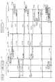
図2Aは、通信アダプタ10の操作パネル30を示す正面図である。 FIG. 2A is a front view showing the
図2Bは、通信アダプタ10の外観を示す斜視図である。 FIG. 2B is a perspective view illustrating an appearance of the
図2Cは、通信アダプタ10の外観を示す側面図である。 FIG. 2C is a side view showing the appearance of the
通信アダプタ10は、上面が手前側に傾斜した箱形の筐体10zを有する。筐体10zは、例えば樹脂材料で成形される。筐体10zの上面には、操作パネル30が配置される。操作パネル30の前面は、表示領域30z、ボタン領域30y、ブランク領域30x、BLFキー領域30w、及び12キー領域に区画される。 The
表示領域30zには、液晶表示器(LCD)15が中央に配置され、その下方に着信用のLED16B、BLE用のLED16A及びソフトキー群34が配置される。ソフトキー群34は、ソフトキーk11,k12,k13を含む。 In the
ボタン領域30yには、ボタン群33が配置される。ボタン群33は、CALLボタンbn1,TRANSFERボタンbn2,HOLDボタンbn3,REDIALボタンbn4,MUTEボタンbn5,MESSAGEボタンbn6,Recordingボタンbn7,及びCANCELボタンbn8を含む。 A
CALLボタンbn1は、発信や転送を行う時に押下される。なお、CALLボタンbn1は、通話の最中に終話する際に押下される。 The CALL button bn1 is pressed when performing transmission or transfer. The CALL button bn1 is pressed when the call is ended during a call.
TRANSFERボタンbn2は、通話を転送する時に押下される。 The TRANSFER button bn2 is pressed when a call is transferred.
HOLDボタンbn3は、保留する時に押下される。 The HOLD button bn3 is pressed when holding.
REDIALボタンbn4は、リダイアル通話を行う時に押下される。 The REDIAL button bn4 is pressed when performing a redial call.
MUTEボタンbn5は、送話の停止時に押下される。 The MUTE button bn5 is pressed when transmission is stopped.
MESSAGEボタンbn6は、留守電を再生する時に押下される。 The MESSAGE button bn6 is pressed when playing back the answering machine.
Recordingボタンbn7は、録音する時に押下される。 The Recording button bn7 is pressed when recording.
CANCELボタンbn8は、通話を終了する時に押下される。また、CANCELボタンbn8は、各操作のキャンセル時にも押下される。 The CANCEL button bn8 is pressed when the call is finished. The CANCEL button bn8 is also pressed when canceling each operation.
ブランク領域30xは、空白である。例えば、このブランク領域30xに、ユーザがメモ等を記したタグシールを貼ってもよい。また、後述するBLFキーに対応するユーザの名前等を記してもよい。 The blank area 30x is blank. For example, a tag sticker on which a user writes a memo or the like may be attached to the blank area 30x. In addition, a user name corresponding to a BLF key to be described later may be written.
BLFキー領域30wには、BLFキー群28が配置される。BLFキー群28は、10個のBLFキーk1〜k10を含む。各BLFキーk1〜k10は、後述する12キー17を用いてダイヤルする代わりに、ワンタッチ操作で、登録されている番号のスマートフォン50に通話を転送したり、登録されている番号のスマートフォン50に発信したり可能なハードキーである。また、各BLFキーk1〜k10は、それぞれBLFキー用のLED18を有する。なお、各BLFキーk1〜k10の押下に伴って通話を転送したり、発信したり可能な電話機はスマートフォン50に限定されず、PBX8に接続されている電話通信端末(例えばIP電話、アナログ電話)でもよい。 A BLF
各BLFキー用のLED18は、それぞれ該当するスマートフォン50のユーザの在席状態・通話状態を表示する。従って、BLFキーk1〜k10に番号が登録されているスマートフォン50のユーザの在席状況及び通話状況は、一目瞭然である。なお、企業内の全てのユーザの在席状態及び通話状態は、前述したPBX8のプレゼンスサーバ8zのテーブルに登録されて管理される。 The
通信アダプタ10は、PBX8から該当するユーザの在席状態及び通話状態の通知を受けると、該当するユーザの番号に対応するBLFキー用のLED18の点灯色を変更する。ここでは、LED18が消灯している(つまり、点灯していない)場合、在席していることを表す。LED18の点灯色が赤色である場合、不在又は通話中であることを表す。なお、在席している場合、さらに、通話中と非通話とで、BLFキー用のLED18の点灯色を異なる色にしてもよい。また、BLFキー用のLED18は、在席状況や通話状態に限らず、「在席しているが電話に出たくない」、「会議中」等、ユーザの状態をユーザの対応中の業務の種類に応じて、区別可能により詳細に表示してもよい。例えば、BLFキー用のLED18は、赤や緑色以外の点灯色に変更してもよいし、点灯数や点滅を変えて点灯してもよい。 The
12キー領域には、12キー17が配置される。12キー17は、数値を入力可能な、「0」〜「9」の数字キー、及び「*」と「#」の記号キーを含む。 In the 12 key area, 12
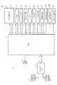
図3は、通信アダプタ10のハードウェア構成を示すブロック図である。 FIG. 3 is a block diagram illustrating a hardware configuration of the
通信アダプタ10は、CPU11、RAM(揮発メモリ)12、フラッシュメモリ(不揮発メモリ)13、BLE処理部(BLEモジュール)14、液晶表示器15、BLE用LED16A、着信用LED16B、及びBLFキー用LED18を有する。 The
CPU11は、メモリとしてのRAM12やフラッシュメモリ13と協働して、各種の制御処理の実行を制御し、通信アダプタ10の動作を統括的に制御する。 The
RAM(揮発メモリ)12は、CPU11のワーキングメモリとして使用される。例えば、RAM12には、PBX8から受信したデータを基に、各BLFキーk1〜k10に対応するユーザの在席状態及び通話状態等が記憶される。 A RAM (volatile memory) 12 is used as a working memory for the
BLFキー用LED18は、RAM12に記憶された在席状態及び通話状態の情報を基に点灯する。 The BLF
フラッシュメモリ13は、不揮発メモリであり、通信アダプタ10の登録情報等を記憶する。登録情報として、例えばBLFキーに対応する、ユーザが所持するスマートフォン50の番号が挙げられる。 The
BLE処理部(BLEモジュールの一例)14は、スマートフォン50とBLE通信を行う。 The BLE processing unit (an example of a BLE module) 14 performs BLE communication with the
液晶表示器15は、例えば4行分の情報やデータを表示可能なディスプレイであり、PBX8から通知される通話先の名称や通話先の電話番号等を表示する。 The
BLE用LED16Aは、スマートフォン50と通信アダプタ10との間のBLE通信の接続状態を示しており、BLE通信が可能な状態(つまり、BLEによって接続されている状態)の時に点灯する。 The
着信用LED16Bは、PBX8から着信があると点滅し、着信後の通話の切断によって消灯する。また、着信用LED16Bは、不在着信で通話相手の電話機から送られたメッセージを保存している状態であることも示す。 The
また、通信アダプタ10は、前述したように、12キー17、BLFキー群28、ボタン群33、ソフトキーk11〜k13を有する他、ブザー19及びネットワークインターフェース(I/F)20を有する。 Further, as described above, the
ブザー19は、例えば着信があった時に鳴動する。ネットワークI/F(IP通信機能)20は、IP通信網(LAN)を制御し、通信アダプタ10とIP通信網90との接続を行う。 The
ネットワークI/F20は、PC用コネクタ21,PBX用コネクタ22を有し、PC用コネクタ21を介してユーザPCと接続され、また、PBX用コネクタ22を介してPBX8及びアクセスポイント70と接続される。 The network I /
図4は、スマートフォン50のハードウェア構成を示すブロック図である。 FIG. 4 is a block diagram illustrating a hardware configuration of the
スマートフォン50は、制御部506、記憶部504及びタッチパネル503を有する。 The
制御部506は、メモリ(例えば記憶部504)と協働して、各種の制御処理の実行を制御し、スマートフォン50の動作を統括的に制御する。 The
記憶部504は、スマートフォン50の動作に必要なプログラム及びデータを記憶するとともに、ユーザにより利用されるアプリケーションプログラム等も記憶する。 The
タッチパネル503は、ユーザのタッチ入力操作(タップ操作等)を受け付け、また、画面に画像やアイコン等を表示する。 The
また、スマートフォン50は、4Gプロトコル制御部502及び4G無線I/F部501を有し、例えば4G(第4世代移動通信システム)の無線通信方式を用いて、モバイル網に接続された携帯電話機や他のスマートフォンと無線接続を行う。なお、スマートフォン50が対応可能な通信規格は、4G(第4世代移動通信システム)に限定されず、例えば3G(第3世代移動通信システム)、5G(第5世代移動通信システム)などの他の通信規格であっても構わない。 The
スマートフォン50は、音声バス515、音声入出力制御部505、スピーカ513及びマイク512を有し、外部に対して音声の入出力を行う。 The
また、スマートフォン50は、IP通信制御部507及びIP通信I/F部508を有し、無線LANで接続されたアクセスポイント70を介してPBX8及び通信アダプタ10と音声データを送受信する。 The
また、スマートフォン50は、BLEモジュール520を有し、BLE(Bluetooth(登録商標) Low Energy)の通信規格を用いて、通信アダプタ10との間でBLE通信を行うための接続の処理(例えばペアリング)や接続後の通信を行う。 Further, the
また、スマートフォン50は、USB通信I/F部511を有し、USB(Universal Serial Bus)規格のインタフェースを有する機器やメモリ等とデータを送受信する。 In addition, the
次に、本実施の形態の通信システム5の動作について、図面を参照して説明する。 Next, the operation of the communication system 5 of the present embodiment will be described with reference to the drawings.
(接続動作)
図5は、通信アダプタ10とスマートフォン50の初回接続動作を示すシーケンス図である。(Connection operation)
FIG. 5 is a sequence diagram illustrating an initial connection operation between the
なお、本明細書に添付する図面のシーケンス図では、スマートフォン50のIP通信機能に付した符号507は図4のIP通信制御部507に対応し、スマートフォン50のBLEに付した符号520は図4のBLEモジュール520に対応する。同様に、通信アダプタ10のIP通信機能に付した符号20は図3のネットワークI/F20に対応し、通信アダプタ10のBLEに付した符号14は図3のBLE処理部14に対応する。また、本明細書に添付する図面のシーケンス図の説明において、スマートフォン50において、IP通信制御部507やBLEモジュール520の動作(処理)は、制御部506からの実行制御に関する指示に基づいて行われる。同様に、本明細書に添付する図面のシーケンス図の説明において、通信アダプタ10において、ネットワークI/F20やBLE処理部14の動作(処理)は、CPU11からの実行制御に関する指示に基づいて行われる。 In the sequence diagram of the drawings attached to this specification,
図5において、通信アダプタ10は、ユーザによってソフトキーk11,k12,k13からの操作、又は設定メニューからの操作によって、BLE処理部14による、スマートフォン50との接続を開始する(T1)。この接続開始時、BLE処理部14は、スマートフォン50に対して自分の存在を示すためにAdvertiseの情報をブロードキャストで配信する(T2)。 In FIG. 5, the
一方、スマートフォン50は、ユーザによってタッチパネル503の接続開始ボタンsn1(図7参照)が押下されると、BLEモジュール520による接続を開始する(T3)。この接続開始時、BLEモジュール520は、Advertiseの情報を配信している通信アダプタ10の有無を走査して確認する(T4)。この走査による確認の結果、BLEモジュール520は、Advertiseの情報を配信している通信アダプタ10を見つけると、見つけた通信アダプタ10との接続を要求するConnectコマンドをBLE処理部14に送信する(T5)。 On the other hand, when the connection start button sn1 (see FIG. 7) of the
BLE処理部14は、BLEモジュール520からの接続要求に対し、応答を表すOKコマンドを返信する(T6)。 In response to the connection request from the
BLEモジュール520は、BLE処理部14に対し、相互通信可能なペアリング接続を要求するPairingコマンドを送信する(T7)。BLE処理部14は、Pairingコマンドを受信すると、ペアリング接続要求に対し、応答を表すOKコマンド(つまり、相互接続の処理結果)を返信する(T8)。これにより、通信アダプタ10とスマートフォン50のBLE通信によるペアリング接続が行われる。 The
BLE通信によるペアリング接続が行われると、BLE処理部14は、通信アダプタ10のIP情報等(例えばIPアドレス、ポート番号を含む)をBLEモジュール520に送信する(T9)。このIP情報は、通信アダプタ10のIP通信機能(つまり、ネットワークI/F20)とスマートフォン50のIP通信機能(つまり、IP通信制御部507)との間でIP通信を行うための情報の受け渡しに使用されており、BLEで通信することにより、スマートフォン60の消費電力を抑えたスタンバイモードから、スマートフォン60の消費電力を抑えないアクティブモードに移行させている。つまり、スタンバイモードからアクティブモードへの遷移は、BLE通信がトリガとなっている。 When pairing connection by BLE communication is performed, the
BLEモジュール520は、BLE処理部14から通信アダプタ10のIP情報等を受信すると、スマートフォン50内部で実行中のアプリケーション50Mに通信アダプタのIP情報等を転送する(T10)。アプリケーション50Mは、スマートフォン50の制御部506が記憶部504から読み出して実行可能である。アプリケーション50Mは、通信アダプタ10のIP情報等を受け取ると、スマートフォン50のIP情報等をBLEモジュール520に転送する(T11)。BLEモジュール520は、BLE処理部14に対し、スマートフォン50のIP情報等を送信する(T12)。 When receiving the IP information and the like of the
上述した手順T1〜T12の実行によって得られたIP情報等を用いて、通信アダプタ10とスマートフォン50とは、IP通信による接続を開始する。アプリケーション50Mが通信アダプタ10のIP情報をIP通信機能(つまり、IP通信制御部507)に転送すると(T13)、IP通信機能(つまり、IP通信制御部507)は、通信アダプタ10のIP通信機能(つまり、ネットワークI/F20)に対し、IP通信の接続を要求するConnectコマンドを送信する(T14)。 The
IP通信機能(つまり、ネットワークI/F20)は、IP通信の接続要求を受信すると、応答を表すOKコマンドをIP通信機能(つまり、IP通信制御部507)に返信する(T15)。 When receiving the IP communication connection request, the IP communication function (that is, the network I / F 20) returns an OK command representing the response to the IP communication function (that is, the IP communication control unit 507) (T15).
IP通信機能(つまり、IP通信制御部507)は、スマートフォン50の状態をIP通信機能(つまり、ネットワークI/F20)に送信する(T16)。IP通信機能(つまり、ネットワークI/F20)は、応答を表すOKコマンドをIP通信機能(つまり、IP通信制御部507)に返信する(T17)。IP通信機能(つまり、IP通信制御部507)は、アプリケーション50Mに接続結果を転送する(T18)。この後、IP通信機能(つまり、IP通信制御部507)は、通信アダプタ10とスマートフォン50との接続確認を終了する(T19)。上述した手順T14〜T19で通信アダプタ10及びスマートフォン50間のIP通信が確認される。このIP通信の接続の確認が終わると、スマートフォン50は、アクティブモードからスタンバイモードに移行する。 The IP communication function (that is, the IP communication control unit 507) transmits the state of the
続いて、通信アダプタ10が、SIP(Session Initiation Protocol)を用いて、PBX8の特番に対して発信する動作を示す。特番とは、一般にPBXの機能(内線、外線、転送、等)を利用する番号であり、ここでは、通信アダプタ10が在席していることを通知する番号を表す。IP通信機能(つまり、ネットワークI/F20)は、PBX8に対し在席していることの通知を表す特番を要求するInviteコマンドを送信する(T20)。PBX8は、このInviteコマンドを受信すると、IP通信機能(つまり、ネットワークI/F20)に対し、応答を表す「100」コマンドを送信する(T21)。更に、PBX8は、鳴動を表す「180」コマンドを送信し(T22)、続けて成功を表す「200」コマンドを送信する(T23)。IP通信機能(つまり、ネットワークI/F20)は、これらのコマンドを受信すると、セッション接続の確認を表すAckコマンドをPBX8に返信する(T24)。 Subsequently, an operation in which the
PBX8は、IP通信機能(つまり、ネットワークI/F20)から特番にかかってきたことで、通信アダプタ10が設置されたデスクにユーザが在席していると判断し、このユーザのプレゼンス状態を「在席」に変更し、プレゼンスサーバ8zを更新する(T25)。 The
通信アダプタ10のプレゼンス状態を変更した後、PBX8は、セッション切断を表すBYEコマンドをIP通信機能(つまり、ネットワークI/F20)に送信する(T26)。IP通信機能(つまり、ネットワークI/F20)は、セッション切断の確認を表すAckコマンドをPBX8に返信する(T27)。 After changing the presence state of the
図6は、通信アダプタ10とスマートフォン50の2回目以降の接続動作を示すシーケンス図である。 FIG. 6 is a sequence diagram illustrating the second and subsequent connection operations between the
2回目以降の接続動作では、既に、通信アダプタ10とスマートフォン50とのペアリングが済んでいるので、図5の手順T7,T8の処理は省かれる。つまり、図6において、BLEモジュール520は、手順T4の走査の結果、見つけた通信アダプタ10のBLE処理部14に対し、すぐさま接続を要求するConnectコマンドを送信する(T5)。BLE処理部14は、BLEモジュール520からの接続要求に対し、応答を表すOKコマンドを返信する(T6)。この後、初回接続動作と同様、通信アダプタ10とスマートフォン50とのIP通信の接続手順が開始する。 In the second and subsequent connection operations, since the pairing between the
このように、2回目以降の接続動作では、ペアリング接続の動作が省略されるので、接続までの時間を短縮できる。 In this way, in the second and subsequent connection operations, the pairing connection operation is omitted, so that the time until connection can be shortened.
なお、ユーザがスマートフォン50を持って席を離れる(つまり、不在にする)ことで、スマートフォン50と通信アダプタ10との間のBLE通信のリンクが外れること(つまり、途切れること)、又はユーザがスマートフォン50の切断キー(図示せず)を押下することにより、、スマートフォン50と通信アダプタ10との切断動作が行われる。 Note that when the user leaves the seat with the smartphone 50 (that is, is absent), the link of the BLE communication between the
図7は、通信アダプタ10とのIP通信接続開始時のスマートフォン50の画面遷移を示す図である。 FIG. 7 is a diagram illustrating a screen transition of the
始めに、スマートフォン50は、タッチパネル503に走査開始画面gm1を表示する。走査開始画面gm1では、接続開始ボタンsn1が表示される。接続開始ボタンsn1が押下されると、スマートフォン50は、タッチパネル503に走査中を表す走査中画面gm2を表示する。走査中画面gm2では、通信相手となる通信アダプタ10が見つかるまで待機マークmk1が動くように表示される。 First, the
走査が終了すると、スマートフォン50は、タッチパネル503に走査結果画面gm3を表示する。走査結果画面gm3では、走査により見つかった通信アダプタ10のリストL1が表示される。ここでは、走査結果として、3つの通信アダプタ10が表示される。ユーザがリストL1に登録された通信アダプタ10の表示位置を押下して選択すると、スマートフォン50は、タッチパネル503に接続確認画面gm4を表示する。接続確認画面gm4では、通信アダプタ10との接続準備ができているか否かを表すメッセージms1、取り消し(Cancel)ボタンsn2及び許可(OK)ボタンsn3が表示される。 When the scanning is completed, the
ユーザがOKボタンsn3を押下すると、スマートフォン50は、タッチパネル503に接続中画面gm5を表示する。接続中画面gm5では、接続中を表す「connecting」のメッセージms2が表示される。接続が完了すると、スマートフォン50は、タッチパネル503にアイドル画面gm6(図11D参照)を表示する。上述した順序で、IP通信接続開始時のスマートフォン50の画面遷移が終了する。 When the user presses the OK button sn3, the
以上により、実施の形態1の通信システム5は、PBX8(電話交換機)と、スマートフォン50(電話通信端末)と、PBX8及びスマートフォン50との間で通話に関する信号を送受信する通信アダプタ10とを含む。通信アダプタ10は、スマートフォン50との接続に関するイベントを検知すると、BLE通信(第1の通信の一例)を用いて、スマートフォン50との間で、スマートフォン50との間の相互接続の処理(例えばペアリング)を行う。スマートフォン50は、通信アダプタ10との間の相互接続の処理の後、IP通信(第2の通信の一例)を用いて、自端末に関する情報を通信アダプタ10に送信する。通信アダプタ10は、BLE通信(第1の通信)を用いた相互接続の処理とIP通信(第2の通信)によってスマートフォン50から送信されたスマートフォン50のIP情報(電話通信端末に関する情報の一例)とに基づいて、PBX8に、通信アダプタ10との間のIP通信が可能なスマートフォン50のユーザが在席していることの通知として、PBX8に特番発信(例えば、Inviteコマンドの信号の送信)を行う。 As described above, the communication system 5 according to the first embodiment includes the PBX 8 (telephone exchange), the smartphone 50 (telephone communication terminal), and the
これにより、通信システム5は、通話相手の電話機からの着信が発生して他の人物の電話機に転送する場合に、その他の人物が在席しているかどうかを迅速に状況確認し、必要に応じて、その他の人物の電話機への着信転送を効率的に支援することができる。 As a result, the communication system 5 promptly checks whether or not another person is present when an incoming call from the other party's telephone is generated and forwarded to the other person's telephone. Thus, it is possible to efficiently support the transfer of incoming calls to other people's telephones.
また、スマートフォン50及び通信アダプタ10は、ユーザ毎にそれぞれ設けられる。PBX8は、PBX8に接続される個々の通信アダプタ10毎に、それぞれの通信アダプタ10とIP通信を用いたスマートフォン50の有無を示す情報を保持するテーブル(メモリの一例)を記憶するプレゼンスサーバ8zを有する。PBX8は、少なくとも1つの通信アダプタ10から送信された、IP通信が可能なスマートフォン50が在席していることの通知を表すInvite信号に基づいて、プレゼンスサーバ8zに記憶されたテーブルを更新する。これにより、PBX8は、電話通信端末をそれぞれ所持する複数のユーザの在席状況を一元管理することができる。 The
また、通信アダプタ10は、BLE通信を用いてペアリング接続(相互接続)の処理を完了した、スマートフォン50の存在を報知する。これにより、ユーザは、自身の在席状態を確認でき、着信待ちの状態や発信可能な状態で待機できる。 Moreover, the
また、通信アダプタ10は、スマートフォン50毎に、スマートフォン50の存在を報知する、BLFキー用LED18(発光部の一例)が配置された複数のBLFキーk1〜k10を有する。通信アダプタ10は、複数のBLFキーk1〜k10にそれぞれ対応する、スマートフォン50の番号をフラッシュメモリ13(第2メモリの一例)に登録しておくことで、PBX8からの情報を基にそれぞれ対応するスマートフォン50の状態を表示できる。これにより、ユーザは、自身及び他のスマートフォンを所持するユーザの在席状態を容易に知ることができ、しかも、在席しているユーザのスマートフォンとの接続に関するイベントをワンタッチ操作で行うことができる。 Moreover, the
(実施の形態2の内容に至る経緯)
上述した特許文献1では、ユーザの所持するスマートフォンを、宅内のコードレス親機に対するコードレス子機として登録して使用できることは開示されている。しかし、特許文献1のような従来技術では、ユーザの所持するスマートフォンを、例えば企業内等に設置された電話交換機に接続可能な業務用のコードレス電話機として利用することは想定されていない。(Background to the contents of the second embodiment)
このため、例えば業務上、通話に関するイベント(例えば着信又は発信)が発生する時、ユーザ(つまり、従業員)は、自分の所持するスマートフォンを手に取って、その通話に関するイベントの内容に合わせて必要な操作を逐一行うことが求められる。ところが、そのような操作に不慣れなユーザにとっては、業務において自分のスマートフォンを用いた操作性が良くないことがあり、業務の一部が遮られることがある等、業務効率の低下を招くことも考えられる。 For this reason, for example, when an event related to a call (for example, incoming call or outgoing call) occurs in business, the user (that is, an employee) picks up his / her smartphone and matches the content of the event related to the call. It is required to perform necessary operations one by one. However, for users who are unfamiliar with such operations, the operability using their smartphones may not be good in the work, and part of the work may be blocked, leading to a decrease in work efficiency. Conceivable.
そこで、実施の形態2では、通話に関するイベントの内容に合わせた必要な操作に不慣れなユーザであっても、業務において自分のスマートフォンをコードレス電話機として利用する際の操作性の劣化を抑制し、業務効率の向上を支援する通信システム、通信方法及び通信アダプタの例を説明する。 Therefore, in the second embodiment, even a user who is unfamiliar with necessary operations in accordance with the contents of the event related to the call suppresses deterioration in operability when using his / her smartphone as a cordless telephone in business, An example of a communication system, a communication method, and a communication adapter that support improvement in efficiency will be described.
(実施の形態2)
実施の形態2における通信システム5の構成は、実施の形態1と同一であるので、同一の符号を用いることで、その説明を省略する。(Embodiment 2)
Since the configuration of the communication system 5 in the second embodiment is the same as that in the first embodiment, the description thereof is omitted by using the same reference numerals.
(着信動作)
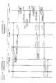
図8は、通信アダプタ10が着信応答を行う場合の着信動作手順を示すシーケンス図である。(Incoming call operation)
FIG. 8 is a sequence diagram showing an incoming call operation procedure when the
図9は、図8に続く通信アダプタが着信応答を行う場合の着信動作手順を示すシーケンス図である。 FIG. 9 is a sequence diagram showing an incoming call operation procedure when the communication adapter following FIG. 8 makes an incoming call response.
なお、本明細書に添付する図面のシーケンス図では、通信アダプタ10のRTPに付した符号40は図3のCPU11に対応し、スマートフォン50のRTPに付した符号510は図4の制御部506に対応する。 In the sequence diagram of the drawings attached to this specification, the
着信動作前、スマートフォン50は、電力消費を抑えたスタンバイモードで動作している。図8において、通信アダプタ10のIP通信機能(つまり、ネットワークI/F20)はPBX8から着信を伝えるInviteコマンドを受信すると(T31)、PBX8に対して、着信応答を表す「100」コマンドを返信する(T32)。BLE処理部14は、スマートフォン50のBLEモジュール520に通信アダプタ10のIP情報を送信する(T33)。このIP情報は、スマートフォン50をスタンバイモードからアクティブモードに移行させるデータ(信号)である。 Prior to the incoming call operation, the
BLEモジュール520は、通信アダプタのIP情報を受け取ると、アプリケーション50Mに転送する(T34)。アプリケーション50Mは、通信アダプタのIP情報を受けると、起動し、スマートフォン50をスタンバイモードからアクティブモードに移行させる(T35)。アプリケーション50Mは、IP通信機能(つまり、IP通信制御部507)に対し、通信アダプタのIP情報を用いてIP通信接続を指示する(T36)。IP通信機能(つまり、IP通信制御部507)は、通信アダプタ10のIP通信機能(つまり、ネットワークI/F20)に対し、IP通信接続を要求するConnectコマンドを送信する(T37)。IP通信機能(つまり、ネットワークI/F20)は、IP通信機能(つまり、IP通信制御部507)に応答を表すOKコマンドを返信する(T38)。IP通信機能(つまり、IP通信制御部507)は、アプリケーション50MにOKコマンドを転送する(T39)。 When receiving the IP information of the communication adapter, the
IP通信機能(つまり、ネットワークI/F20)は、IP通信機能(つまり、IP通信制御部507)に着信開始を送信する(T40)。この着信開始では、IP通信機能(つまり、ネットワークI/F20)は、IP通信機能(つまり、IP通信制御部507)に対し、PBX8に接続された相手先の名前、番号を通知する。IP通信機能(つまり、IP通信制御部507)は、アプリケーション50Mに相手先の名前、番号を転送する(T41)。 The IP communication function (that is, the network I / F 20) transmits an incoming call start to the IP communication function (that is, the IP communication control unit 507) (T40). At the start of the incoming call, the IP communication function (that is, the network I / F 20) notifies the IP communication function (that is, the IP communication control unit 507) of the name and number of the other party connected to the
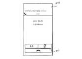
アイドル画面gm6において、通信アダプタ10からの着信を受けると、アプリケーション50Mは、スマートフォン50のタッチパネル503に、着信画面gm7を表示し、スピーカ513に着信音を鳴動させる(T42)。 When receiving an incoming call from the
図11Aは、着信画面gm7を示す図である。 FIG. 11A shows the incoming call screen gm7.
着信画面gm7には、着信の表示「Incoming CALL」、通話開始ボタンsn6、通話終了ボタンsn7等が表示される。 The incoming call screen gm7 displays an incoming call display “Incoming CALL”, a call start button sn6, a call end button sn7, and the like.
アプリケーション50Mは、着信を開始したことをIP通信機能(つまり、IP通信制御部507)に返す(T43)。IP通信機能(つまり、IP通信制御部507)は、通信アダプタ10のIP通信機能(つまり、IP通信制御部507)に着信を開始したことを返信する(T44)。IP通信機能(つまり、ネットワークI/F20)は、PBX8に対し、スマートフォン50が鳴動したことを表す「180」コマンドを返信する(T45)。 The
ユーザが通信アダプタ10のCALLボタンbn1を押下して着信応答すると、IP通信機能(つまり、ネットワークI/F20)は、着信応答したことを表す「200」コマンドをPBX8に送信する(T47)。「200」コマンドのSDPは、通話に使用されるプロトコル等の情報を含む。PBX8は、「200」コマンドを受信すると、IP通信機能(つまり、ネットワークI/F20)に応答を表すAckを返信する(T48)。 When the user presses the CALL button bn1 of the
IP通信機能(つまり、ネットワークI/F20)は、RTP(Real time Transports Protocol)開始をIP通信機能(つまり、IP通信制御部507)に送信する(T49)。スマートフォン50において、RTP開始では、IP通信機能(つまり、IP通信制御部507)は、アプリケーション50MにRTP開始の指示を転送する(T50)。 The IP communication function (that is, the network I / F 20) transmits an RTP (Real time Transports Protocol) start to the IP communication function (that is, the IP communication control unit 507) (T49). In the
アプリケーション50Mは、RTP開始の指示を受け取ると、RTP510(つまり、制御部506)にポート開放を要求する(T51)。RTP510(つまり、制御部506)は、制御部506において実行される。RTP510(つまり、制御部506)は、この要求に応じて、ポートを開放し(T52)、この開放結果をアプリケーション50Mに返す(T53)。アプリケーション50Mは、RTP開始結果をIP通信機能(つまり、IP通信制御部507)に送信する(T54)。RTP開始結果は、スマートフォン50のIPアドレス、ポート番号を含む。 Upon receiving the RTP start instruction, the
IP通信機能(つまり、IP通信制御部507)は、RTP開始結果をIP通信機能(つまり、ネットワークI/F20)に返信する(T55)。RTP40(つまり、CPU11)は、ポートを開放する(T57)。 The IP communication function (ie, IP communication control unit 507) returns the RTP start result to the IP communication function (ie, network I / F 20) (T55). The RTP 40 (that is, the CPU 11) opens the port (T57).
アプリケーション50Mは、通話画面gm9を表示する(T58)。 The
図11Bは、通話画面gm9を示す図である。 FIG. 11B is a diagram showing a call screen gm9.
通話画面gm9には、通話相手の名前、番号、通話中の表示「Talking」、通話時間、通話終了ボタンsn7等が表示される。アプリケーション50Mは、RTP510(つまり、制御部506)と音声接続を行う(T59)。RTP40(つまり、CPU11)とRTP510(つまり、制御部506)とがRTP通信で接続されることで、通信アダプタ10は、PBX8に接続された通話相手とスマートフォン50との間で転送される音声データを中継する(T60)。 On the call screen gm9, the name and number of the other party, a “Talking” display during a call, a call time, a call end button sn7, and the like are displayed. The
続いて、スマートフォン50が着信応答を行う場合の着信動作を示す。 Subsequently, an incoming call operation when the
図10は、スマートフォン50が着信応答を行う場合の着信動作手順を示すシーケンス図である。 FIG. 10 is a sequence diagram showing an incoming call operation procedure when the
前述した手順T31〜T45までの動作は、スマートフォン50が着信応答を行う場合も同様である。 The operations from steps T31 to T45 described above are the same when the
アプリケーション50Mは、ユーザの操作による着信応答を受け付けると(T71)、IP通信機能(つまり、IP通信制御部507)に着信応答を送信する(T72)。IP通信機能(つまり、IP通信制御部507)は、IP通信機能(つまり、ネットワークI/F20)に着信応答を転送する(T73)。IP通信機能(つまり、ネットワークI/F20)は、スマートフォン50が着信応答したことを表す「200」コマンドをPBX8に送信する(T74)。 When the
IP通信機能(つまり、ネットワークI/F20)は、着信応答の結果をIP通信機能(つまり、IP通信制御部507)に送信する(T75)。IP通信機能(つまり、IP通信制御部507)は、アプリケーション50Mに着信応答の結果を転送する(T76)。 The IP communication function (that is, the network I / F 20) transmits the result of the incoming call response to the IP communication function (that is, the IP communication control unit 507) (T75). The IP communication function (that is, the IP communication control unit 507) transfers the result of the incoming call response to the
また、IP通信機能(つまり、ネットワークI/F20)は、RTP開始及び付加情報(コーデック、IPアドレス、ポート番号、SRTP(Secure Real time Transport Protocol))をIP通信機能(つまり、IP通信制御部507)に送信する(T77)。IP通信機能(つまり、IP通信制御部507)は、アプリケーション50MにRTP開始及び付加情報を転送する(T78)。 Further, the IP communication function (that is, the network I / F 20) is configured such that the RTP start and additional information (codec, IP address, port number, SRTP (Secure Real Time Transport Protocol)) are transferred to the IP communication function (that is, the IP communication control unit 507). (T77). The IP communication function (that is, the IP communication control unit 507) transfers the RTP start and additional information to the
アプリケーション50Mは、RTP510(つまり、制御部506)にポート開放を指示する(T79)。RTP510(つまり、制御部506)は、この指示に従い、ポートを開放し(T80)、開放結果をアプリケーション50Mに返す(T81)。アプリケーション50Mは、RTP開始結果をIP通信機能(つまり、IP通信制御部507)に送信する(T82)。RTP開始結果は、スマートフォン50のIPアドレス及びポート番号を含む。 The
IP通信機能(つまり、IP通信制御部507)は、RTP開始結果をIP通信機能(つまり、ネットワークI/F20)に転送する(T83)。加えてIP通信機能(つまり、ネットワークI/F20)が、手順T74の「200」コマンドの応答として、PBX8からAckを受信することによって(T84)、RTP40(つまり、CPU11)は、ポートを開放する(T85)。 The IP communication function (that is, IP communication control unit 507) transfers the RTP start result to the IP communication function (that is, network I / F 20) (T83). In addition, when the IP communication function (that is, the network I / F 20) receives Ack from the
アプリケーション50Mは、前述した通話画面gm9を表示する(T86)。アプリケーション50Mは、RTP510(つまり、制御部506)と音声接続を行う(T87)。RTP40(つまり、CPU11)とRTP510(つまり、制御部506)とが接続されることで、通信アダプタ10は、PBX8に接続された通話相手と、スマートフォン50との間で転送される音声データを中継する(T88)。 The
(発信動作)
図12は、発信動作手順を示すシーケンス図である。(Outgoing action)
FIG. 12 is a sequence diagram showing a transmission operation procedure.
図13は、図12に続く発信動作手順を示すシーケンス図である。 FIG. 13 is a sequence diagram showing a transmission operation procedure following FIG.
発信動作前、スマートフォン50は、電力消費を抑えたスタンバイモードで動作している。図12において、ユーザが通信アダプタ10に対し、12キー17を押下して番号を入力し、CALLボタンbn1を押下すると、BLE処理部14は、発信指示を行う(T101)。なお、BLFキーに発信先の番号が登録されている場合、12キーの代わりにBLFキーを押下してもよく、ワンタッチ操作で発信が可能となる。BLE処理部14は、通信アダプタ10のIP情報をスマートフォン50に送信する(T102)。 Prior to the transmission operation, the
スマートフォン50のBLEモジュール520は、BLE処理部14から通信アダプタ10のIP情報を受信すると、アプリケーション50Mに転送する(T103)。アプリケーション50Mは、起動し、スマートフォン50をスタンバイモードからアクティブモードに移行させる(T104)。アプリケーション50Mは、IP通信機能(つまり、IP通信制御部507)に通信アダプタ10のIP情報を通知し、IP通信接続を指示する(T105)。 When receiving the IP information of the
IP通信機能(つまり、IP通信制御部507)は、通信アダプタ10のIP通信機能(つまり、ネットワークI/F20)にConnectコマンドを送信して接続を行う(T106)。IP通信機能(つまり、ネットワークI/F20)は、接続の許可を表すOKコマンドをIP通信機能(つまり、IP通信制御部507)に返信する(T107)。IP通信機能(つまり、IP通信制御部507)は、OKコマンドを受信すると、アプリケーション50Mに転送する(T108)。 The IP communication function (that is, the IP communication control unit 507) transmits a Connect command to the IP communication function (that is, the network I / F 20) of the
続けて、IP通信機能(つまり、ネットワークI/F20)は、発信開始(相手先の名前及び番号を含む)をIP通信機能(つまり、IP通信制御部507)に送信する(T109)。IP通信機能(つまり、IP通信制御部507)は、発信開始(相手先の名前及び番号を含む)を受信すると、アプリケーション50Mに転送する(T110)。 Subsequently, the IP communication function (that is, the network I / F 20) transmits a call start (including the name and number of the other party) to the IP communication function (that is, the IP communication control unit 507) (T109). When the IP communication function (that is, the IP communication control unit 507) receives the transmission start (including the name and number of the other party), the IP communication function transfers it to the
アプリケーション50Mは、タッチパネル503に発信画面gm8を表示する。 The
図11Cは、発信画面gm8を示す図である。 FIG. 11C is a diagram showing a transmission screen gm8.
発信画面gm8には、通話相手の名前、番号、通話終了ボタンsn7等が表示される。 The call screen gm8 displays the name, number, call end button sn7, etc. of the other party.
アプリケーション50Mは、発信開始結果をIP通信機能507に返す(T112)。IP通信機能507は、発信開始結果をIP通信機能(つまり、ネットワークI/F20)に送信する(T113)。IP通信機能(つまり、ネットワークI/F20)は、PBX8に対し、電話をかけることを表すInviteコマンドを送信する(T114)。PBX8は、電話の応答を表す「100」コマンドをIP通信機能(つまり、ネットワークI/F20)に返信する(T115)。さらに、PBX8は、相手先の電話機が鳴動していることを表す「180」コマンドをIP通信機能(つまり、ネットワークI/F20)に送信する(T116)。 The
IP通信機能(つまり、ネットワークI/F20)は、RBT(リングバックトーン:呼出音)開始をスマートフォン50のIP通信機能(つまり、IP通信制御部507)に送信する(T117)。IP通信機能(つまり、IP通信制御部507)は、RBT開始をアプリケーション50Mに転送する(T118)。アプリケーション50Mは、RBT開始を受けると、スピーカ513から呼出音を鳴動する(T119)。アプリケーション50Mは、RBT開始結果をIP通信機能(つまり、IP通信制御部507)に返す(T120)。IP通信機能(つまり、IP通信制御部507)は、RBT開始結果をIP通信機能(つまり、ネットワークI/F20)に送信する(T121)。 The IP communication function (that is, the network I / F 20) transmits an RBT (ringback tone: ringing tone) start to the IP communication function (that is, the IP communication control unit 507) of the smartphone 50 (T117). The IP communication function (that is, the IP communication control unit 507) transfers the RBT start to the
IP通信機能(つまり、ネットワークI/F20)は、PBX8から通話先の相手が応答した(電話に出た)ことを表す「200」コマンド(SDPを含む)を受信すると(T122)、IP通信機能(つまり、IP通信制御部507)にRTP開始を送信する(T123)。RTP開始は、付加情報(コーデック、IPアドレス、ポート番号、SRTP)を含む。 When the IP communication function (that is, the network I / F 20) receives a “200” command (including SDP) indicating that the other party has responded (answered a call) from the PBX 8 (T122), the IP communication function In other words, the RTP start is transmitted to (IP communication control unit 507) (T123). The RTP start includes additional information (codec, IP address, port number, SRTP).
IP通信機能(つまり、IP通信制御部507)は、RTP開始をアプリケーション50Mに転送する(T124)。アプリケーション50Mは、RTP開始を受けると、RTP510(つまり、制御部506)にポート開放を指示する(T125)。RTP510(つまり、制御部506)は、この指示に従い、ポートを開放し(T126)、開放結果をアプリケーション50Mに返す(T127)。アプリケーション50Mは、RTP開始結果をIP通信機能(つまり、IP通信制御部507)に送信する(T128)。RTP開始結果は、IPアドレス、ポート番号を含む。IP通信機能(つまり、IP通信制御部507)は、IP通信機能(つまり、ネットワークI/F20)にRTP開始結果を送信する(T129)。IP通信機能(つまり、ネットワークI/F20)は、手順T122における「200」コマンドの応答として、スマートフォン50と同期が取れたことを表すAckコマンドを返信する(T130)。RTP40(つまり、CPU11)は、ポートを開放する(T131)。 The IP communication function (that is, the IP communication control unit 507) transfers the RTP start to the
アプリケーション50Mは、タッチパネル503に、前述した通話画面gm9(図11B参照)を表示する(T132)。アプリケーション50Mは、RTP510(つまり、制御部506)と音声接続を行う(T133)。この後、通信アダプタ10は、通信アダプタ10とスマートフォン50との間で転送される音声データを中継する(T134)。 The
(通話転送)
図14は、通話転送の動作を示すシーケンス図である。(Call transfer)
FIG. 14 is a sequence diagram showing a call transfer operation.
図15は、図14に続く通話転送の動作を示すシーケンス図である。 FIG. 15 is a sequence diagram showing the call transfer operation following FIG.
図16は、図14及び図15に続く通話転送の動作を示すシーケンス図である。 FIG. 16 is a sequence diagram showing the call transfer operation following FIGS. 14 and 15.
図14において、PBX8に接続されている通話先の電話機(電話通信端末)と、スマートフォン50との通話中(T201)、ユーザが通信アダプタ10のTRANSFERボタンbn2を押下して通話転送を指示すると、通信アダプタ10のIP通信機能(つまり、ネットワークI/F20)は、転送開始を行う(T202)。 In FIG. 14, when the user presses the TRANSFER button bn2 of the
IP通信機能(つまり、ネットワークI/F20)は、通話一時切断をスマートフォン50のIP通信機能(つまり、IP通信制御部507)に送信する(T203)。IP通信機能(つまり、IP通信制御部507)は、通話一時切断をアプリケーション50Mに転送する(T204)。アプリケーション50Mは、通話一時切断を受けると、音声を切断する(T205)。アプリケーション50Mは、ポートの閉鎖をRTP510(つまり、制御部506)に指示する(T206)。RTP510(つまり、制御部506)は、この指示に従い、ポートを閉鎖し(T207)、閉鎖結果をアプリケーション50Mに返す(T208)。アプリケーション50Mは、通話画面gm9(図11B参照)から発信画面gm8(図11C参照)に表示を切り替える(T209)。アプリケーション50Mは、通話一時切断結果をIP通信機能(つまり、IP通信制御部507)に送信する(T210)。IP通信機能(つまり、IP通信制御部507)は、IP通信機能(つまり、ネットワークI/F20)に通話一時切断結果を送信する(T211)。 The IP communication function (that is, the network I / F 20) transmits the temporary call disconnection to the IP communication function (that is, the IP communication control unit 507) of the smartphone 50 (T203). The IP communication function (that is, the IP communication control unit 507) transfers the temporary call disconnection to the
IP通信機能(つまり、ネットワークI/F20)は、通話一時切断結果を受信すると、DT(ダイヤルトーン)開始をIP通信機能(つまり、IP通信制御部507)に送信する(T212)。IP通信機能(つまり、IP通信制御部507)は、アプリケーション50MにDT開始を転送する(T213)。アプリケーション50Mは、DT開始を受けると、ダイヤルトーンの鳴動を開始する(T214)。アプリケーション50Mは、DT開始結果をIP通信機能(つまり、IP通信制御部507)に返す(T215)。IP通信機能(つまり、IP通信制御部507)は、IP通信機能(つまり、ネットワークI/F20)にDT開始結果を送信する(T216)。 When the IP communication function (that is, the network I / F 20) receives the call temporary disconnection result, it transmits a DT (dial tone) start to the IP communication function (that is, the IP communication control unit 507) (T212). The IP communication function (that is, the IP communication control unit 507) transfers the DT start to the
IP通信機能(つまり、ネットワークI/F20)は、PBX8側との通話(第1呼)を一旦保留にする、Re−InviteコマンドをPBX8に送信する(T217)。PBX8は、通話の一旦保留を受け付けたことを表す「200」コマンドをIP通信機能(つまり、ネットワークI/F20)に返信する(T218)。 The IP communication function (that is, the network I / F 20) transmits a Re-Invite command to the
ユーザが通信アダプタ10に対し、12キー17を押下して転送先(第2呼)の番号を入力し、CALLボタンbn1を押下すると、IP通信機能(つまり、ネットワークI/F20)は、発信指示を行う(T219)。なお、BLFキーに転送先の番号が登録されている場合、12キーの代わりにBLFキーを押下してもよく、ワンタッチ操作で発信が可能となる。IP通信機能(つまり、ネットワークI/F20)は、IP通信機能(つまり、IP通信制御部507)に対し、第2呼の発信開始を送信する(T220)。IP通信機能(つまり、IP通信制御部507)は、アプリケーション50Mに第2呼の発信開始を転送する(T221)。第2呼の発信開始は、通話相手の名前、番号を含む。アプリケーション50Mは、前述した発信画面gm8(図11C参照)を表示する(T222)。 When the user presses the 12 key 17 and inputs the transfer destination (second call) number to the
アプリケーション50Mは、発信開始結果をIP通信機能(つまり、IP通信制御部507)に返す(T223)。IP通信機能(つまり、IP通信制御部507)は、IP通信機能(つまり、ネットワークI/F20)に発信開始結果を送信する(T224)。IP通信機能(つまり、ネットワークI/F20)は、発信開始結果を受信すると、PBX8に電話(第2呼)をかけることを表すInviteコマンドを送信する(T225)。 The
PBX8は、電話を受けたこと(応答)を表す「100」コマンドをIP通信機能(つまり、ネットワークI/F20)に返信する(T226)。さらに、PBX8は、相手の電話機が鳴動中であることを表す「180」コマンドをIP通信機能(つまり、ネットワークI/F20)に送信する(T227)。IP通信機能(つまり、ネットワークI/F20)は、RBT(リングバックトーン:呼出音)開始をスマートフォン50のIP通信機能(つまり、IP通信制御部507)に送信する(T228)。IP通信機能(つまり、IP通信制御部507)は、アプリケーション50MにRBT開始を転送する(T229)。アプリケーション50Mは、RBT開始を受けると、スピーカ513から呼出音を鳴動する(T230)。アプリケーション50Mは、RBT開始結果をIP通信機能(つまり、IP通信制御部507)に返す(T231)。IP通信機能(つまり、IP通信制御部507)は、IP通信機能(つまり、ネットワークI/F20)にRBT開始結果を送信する(T232)。 The
PBX8は、転送先の通話相手が電話に応答したことを表す「200」コマンド(SDPを含む)をIP通信機能(つまり、ネットワークI/F20)に送信する(T233)。IP通信機能(つまり、ネットワークI/F20)は、IP通信機能(つまり、IP通信制御部507)に、転送先との通話開始を表すRTP開始を送信する(T234)。RTP開始は、付加情報(コーデック、IPアドレス、ポート番号、SRTP)を含む。IP通信機能(つまり、IP通信制御部507)は、アプリケーション50MにRTP開始を転送する(T235)。 The
アプリケーション50Mは、RTP開始を受けると、RTP510(つまり、制御部506)にポート開放を指示する(T236)。RTP510(つまり、制御部506)は、この指示に従い、ポートを開放し(T237)、開放結果をアプリケーション50Mに返す(T238)。アプリケーション50Mは、RTP開始結果をIP通信機能(つまり、IP通信制御部507)に送信する(T239)。RTP開始結果は、IPアドレス、ポート番号を含む。IP通信機能(つまり、IP通信制御部507)は、IP通信機能(つまり、ネットワークI/F20)にRTP開始結果を送信する(T240)。IP通信機能(つまり、ネットワークI/F20)は、手順T225におけるInviteコマンドの応答として、スマートフォン50と同期が取れたことを表すAckコマンドを返信する(T241)。RTP40(つまり、CPU11)は、ポートを開放する(T242)。 Upon receiving the RTP start, the
スマートフォン50のアプリケーション50Mは、タッチパネル503に前述した通話画面gm9(図11B参照)を表示する(T243)。アプリケーション50Mは、RTP510(つまり、制御部506)と音声接続を行う(T244)。この後、通信アダプタ10は、通信アダプタ10とスマートフォン50との間で転送される音声データを中継する(T245)。 The
ユーザがTRANSFERボタンbn2を押下して転送実行を指示すると、通信アダプタ10のIP通信機能(つまり、ネットワークI/F20)は、転送を実行する(T246)。IP通信機能(つまり、ネットワークI/F20)は、第1呼の転送を表すReferコマンドをPBX8に送信し(T247)、元の通信(第1呼)を転送する旨をPBX8に指示する。PBX8は、この指示を受諾したことを表す「202」コマンドをIP通信機能(つまり、ネットワークI/F20)に返信する(T248)。IP通信機能(つまり、ネットワークI/F20)は、応答を表す「200」コマンドをPBX8に送信する(T249)。さらに、PBX8は、BYEコマンドをIP通信機能(つまり、ネットワークI/F20)に送信し、転送先の通信(第2呼)との音声通話を切断する(T250)。IP通信機能(つまり、ネットワークI/F20)は、この切断の応答を表すAckコマンドをPBX8に返信する(T251)。 When the user presses the TRANSFER button bn2 to instruct transfer execution, the IP communication function (that is, the network I / F 20) of the
通信アダプタ10のRTP40(つまり、CPU11)は、ポートを閉鎖する(T252)。IP通信機能(つまり、ネットワークI/F20)は、通話切断をスマートフォン50のIP通信機能(つまり、IP通信制御部507)に送信する(T253)。IP通信機能(つまり、IP通信制御部507)は、アプリケーション50Mに通話切断を転送する(T254)。アプリケーション50Mは、通話切断を受けると、音声を切断し(T255)、RTP510(つまり、制御部506)にポートの閉鎖を指示する(T256)。RTP510(つまり、制御部506)は、この指示に従ってポートを閉鎖し(T257)、ポートの閉鎖結果をアプリケーション50Mに返す(T258)。アプリケーション50Mは、タッチパネル503にアイドル(Idle)画面gm6(図11D参照)を表示する(T258)。 The RTP 40 (that is, the CPU 11) of the
図11Dは、アイドル画面gm6を示す図である。 FIG. 11D is a diagram showing an idle screen gm6.
アプリケーション50Mは、通話切断結果をIP通信機能(つまり、IP通信制御部507)に返す(T260)。IP通信機能(つまり、IP通信制御部507)は、IP通信機能(つまり、ネットワークI/F20)に通話切断結果を転送する(T261)。IP通信機能(つまり、IP通信制御部507)は、IP通信を遮断する(T262)。 The
PBX8は、BYEコマンドをIP通信機能(つまり、ネットワークI/F20)に送信し、転送元の通信(第1呼の一例)との音声通話の切断する旨を通知する(T263)。IP通信機能(つまり、ネットワークI/F20)は、切断の応答を表すAckコマンドをPBX8に返信する(T264)。 The
以上により、実施の形態2の通信システム5では、PBX8(電話交換機の一例)と、スマートフォン50(電話通信端末の一例)と、PBX8及びスマートフォン50との間で通話に関する信号を送受信する通信アダプタ10とが接続される。通信アダプタ10は、着信、発信等、通話に関するイベントを検知すると、スマートフォン50との間で、BLE通信(第1の通信の一例)により、イベントの情報をスマートフォン50に送信する。スマートフォン50は、通信アダプタ10から送信されたイベントの情報に基づいて、イベントの発生を報知する。通信アダプタ10は、イベントの発生の報知後、Inviteコマンドや「180」コマンド等(イベントの応答準備の完了を示す信号)を、PBX8に送信する。 As described above, in the communication system 5 according to the second embodiment, the
これにより、通信システム5は、通話に関するイベントの内容に合わせた必要な操作に不慣れなユーザであっても、業務において自分のスマートフォンをコードレス電話機として利用する際の操作性の劣化を抑制し、業務効率の向上を支援することができる。 As a result, the communication system 5 suppresses deterioration of operability when using a user's own smartphone as a cordless phone even in the case of a user who is unfamiliar with necessary operations in accordance with the contents of events related to a call. It can help improve efficiency.
また、通信アダプタ10は、通話に関するイベントを検知すると、BLE通信(第1の通信の一例)によりIP通信の情報を送信することにより、スタンバイモードに設定されていたスマートフォン50をアクティブモードに移行させるための信号をスマートフォン50に送信する。スマートフォン50は、通信アダプタ10から送信されたアクティブモードに移行させるための信号に基づいて、スタンバイモードからアクティブモードに移行する。これにより、通信アダプタ10は、着信や発信等(通話に関するイベントの一例)が検知されない場合、スタンバイモードに移行するので、スマートフォン50の消費電力を抑えることができる。 Further, when the
また、通信アダプタ10は、着信や発信等のイベントの応答操作が行われた場合、スマートフォン50とPBX8に接続された他の電話通信端末との間で音声通話に関する信号を中継する。これにより、通信アダプタが中継することで、スマートフォン50を所持するユーザは、通常の操作と同様、簡単な操作で着信や発信等を行うことができる。 Moreover, the
また、スマートフォン50は、音声通話時(つまり、音声通話に関する信号の通信時)、通話画面(通話に関する画面の一例)を表示する。これにより、ユーザは、着信画面、通話画面、発信画面等、通話に関する画面を見て、通話状態を確認できる。 In addition, the
また、通話に関するイベントは、着信である。これにより、ユーザは、着信において、通信アダプタを利用できる。 An event related to a call is an incoming call. As a result, the user can use the communication adapter for incoming calls.
また、通信アダプタ10は、CALLボタンbn1の押下(着信の応答操作の一例)を検知すると、「200」コマンド(着信の応答操作の検知を示す信号)をPBX8に送信する。これにより、ユーザは、通信アダプタに対し、着信応答の操作を行うことができる。例えば、スマートフォンが上着のポケットに入ったままで直ぐに取り出せないような状況であっても、デスクに設置された通信アダプタを使って着信に対して応答できる。 Further, when the
また、スマートフォン50は、通話開始ボタンsn6の押下(着信の応答操作の一例)を検知すると、「200」コマンド(着信の応答操作の検知を示す信号)を通信アダプタ10に送信する。これにより、ユーザは、スマートフォンに対し、着信応答の操作を行うことができる。通信アダプタに着信があっても、自分のスマートフォンを使用して通常通り、着信応答を行うことができる。従って、着信応答の操作が簡便となる。 When the
また、通話に関するイベントは、発信である。これにより、ユーザは、発信において、通信アダプタを利用できる。 An event related to a call is an outgoing call. Thus, the user can use the communication adapter for outgoing calls.
また、通信アダプタ10は、CALLボタンbn1の押下(発信の操作の一例)を検知すると、Inviteコマンド(発信の操作の検知を示す信号)をスマートフォン50に送信する。これにより、ユーザは、通信アダプタに対し、発信の操作を行うことができる。例えば、スマートフォンが上着のポケットに入ったままで直ぐに取り出せないような状況であっても、デスクに設置された通信アダプタを使って発信できる。また、ユーザは、発信時、通信アダプタに登録された相手先の番号を利用することができる。 Further, when the
また、通信アダプタ10は、TRANSFERボタンbn2の押下(転送開始操作の一例)を検知すると、PBX8に対し、現在の通話相手の電話通信端末との通話を保留させる。これにより、ユーザは、通信アダプタに対し、転送開始操作を行うことができる。また、転送開始操作だけで、現在の通話相手の電話通信端末との通話を保留することができ、操作が簡便である。 Further, when the
また、通信アダプタ10は、12キー17による転送先番号の入力操作を検知すると、PBX8に対し、転送先の電話通信端末との間で通話を開始させる。これにより、ユーザは、通信アダプタに対し、転送先番号の入力操作を行うことができる。現在の通話相手の電話通信端末との通話が保留の状態にあるので、ユーザは、ゆっくりと落ち着いて転送先番号を入力できる。また、転送先番号が入力し終わると、転送先の電話通信端末と通話を開始することができ、通話を転送することの用件を伝えることができる。 When the
また、通信アダプタ10は、TRANSFERボタンbn2の押下(転送実行操作)を検知すると、PBX8に対し、保留中の現在の通話相手の電話通信端末と転送先の電話通信端末との通話を実行させる。これにより、ユーザは、通信アダプタに対し、転送実行操作を行うことができる。また、転送実行操作を行うだけで、通話を転送でき、操作が簡便である。このように、ユーザは、自身のスマートフォンにかかってきた通話を、通信アダプタに対する操作だけで、簡単に転送先の電話通信端末に転送することができる。 Further, when the
以上、図面を参照しながら各種の実施形態について説明したが、本開示はかかる例に限定されないことは言うまでもない。当業者であれば、特許請求の範囲に記載された範疇内において、各種の変更例又は修正例に想到し得ることは明らかであり、それらについても当然に本開示の技術的範囲に属するものと了解される。また、発明の趣旨を逸脱しない範囲において、上述実施の形態における各構成要素を任意に組み合わせてもよい。 While various embodiments have been described above with reference to the drawings, it goes without saying that the present disclosure is not limited to such examples. It will be apparent to those skilled in the art that various changes and modifications can be made within the scope of the claims, and these are naturally within the technical scope of the present disclosure. Understood. In addition, the constituent elements in the above-described embodiment may be arbitrarily combined within the scope not departing from the spirit of the invention.
本開示は、通話に関するイベントの内容に合わせた必要な操作に不慣れなユーザであっても、業務において自分のスマートフォンをコードレス電話機として利用する際の操作性の劣化を抑制し、業務効率の向上を支援する通信システム、通信方法及び通信アダプタとして有用である。 This disclosure can improve the operational efficiency by suppressing the deterioration of operability when using a user's smartphone as a cordless phone even in the case of a user who is unfamiliar with the necessary operation according to the contents of the event related to the call. It is useful as a communication system, a communication method, and a communication adapter to support.
5 通信システム
8 PBX
10 通信アダプタ
11 CPU
12 RAM
13 フラッシュメモリ
14 BLE処理部
15 液晶表示器
16A BLE用LED
16B 着信用BLE
17 12キー
18 BLFキー用LED
19 ブザー
20 ネットワークI/F
21 PC用コネクタ
22 PBX用コネクタ
28 BLFキー群
33 ボタン群
34 ソフトキー群
50 スマートフォン5
10
12 RAM
13
16B BLE for incoming calls
17 12 key 18 BLF key LED
19
21 Connector for
Claims (14)
Translated fromJapanese前記通信アダプタは、
前記通話に関するイベントを検知すると、前記電話通信端末との間で、第1の通信により、前記イベントの情報を前記電話通信端末に送信し、
前記電話通信端末は、
前記通信アダプタから送信された前記イベントの情報に基づいて、前記イベントの発生を報知し、
前記通信アダプタは、
前記イベントの発生の報知後、前記電話通信端末における前記イベントの応答準備の完了を示す信号を、前記電話交換機に送信する、
通信システム。A communication system in which a telephone exchange, a telephone communication terminal, and a communication adapter for transmitting and receiving signals related to a call between the telephone exchange and the telephone communication terminal are connected,
The communication adapter is
When an event related to the call is detected, the event information is transmitted to the telephone communication terminal by the first communication with the telephone communication terminal.
The telephone communication terminal is
Based on the information on the event transmitted from the communication adapter, inform the occurrence of the event,
The communication adapter is
After notifying the occurrence of the event, a signal indicating completion of response preparation of the event in the telephone communication terminal is transmitted to the telephone exchange.
Communications system.
前記電話通信端末は、前記通信アダプタから送信された前記アクティブモードに移行させるための信号に基づいて、前記スタンバイモードから前記アクティブモードに移行する、
請求項1に記載の通信システム。When the communication adapter detects an event related to the call, the communication adapter transmits a signal for shifting the telephone communication terminal set in the standby mode to the active mode by the first communication to the telephone communication terminal;
The telephone communication terminal shifts from the standby mode to the active mode based on a signal for shifting to the active mode transmitted from the communication adapter.
The communication system according to claim 1.
請求項1に記載の通信システム。The communication adapter relays a signal related to a voice call between the telephone communication terminal and another telephone communication terminal connected to the telephone exchange when a response operation of the event is performed.
The communication system according to claim 1.
請求項3に記載の通信システム。The telephone communication terminal displays a screen related to a call during communication of a signal related to the voice call.
The communication system according to claim 3.
請求項3に記載の通信システム。The event related to the call is an incoming call.
The communication system according to claim 3.
請求項5に記載の通信システム。When the communication adapter detects the incoming response operation, the communication adapter transmits a signal indicating detection of the incoming response operation to the telephone exchange.
The communication system according to claim 5.
請求項5に記載の通信システム。When the telephone communication terminal detects the incoming response operation, the telephone communication terminal transmits a signal indicating detection of the incoming response operation to the communication adapter.
The communication system according to claim 5.
請求項3に記載の通信システム。The event related to the call is an outgoing call.
The communication system according to claim 3.
請求項8に記載の通信システム。When the communication adapter detects the call operation, the communication adapter transmits a signal indicating the detection of the call operation to the telephone communication terminal.
The communication system according to claim 8.
請求項5に記載の通信システム。The communication adapter, when detecting a transfer start operation, causes the telephone exchange to hold a call with a telephone communication terminal of a current call partner,
The communication system according to claim 5.
請求項10に記載の通信システム。When the communication adapter detects an input operation of a transfer destination number, the telephone exchange starts a call with the transfer destination telephone communication terminal.
The communication system according to claim 10.
請求項11に記載の通信システム。The communication adapter, when detecting a transfer execution operation, causes the telephone exchange to execute a call between the telephone communication terminal of the current call partner on hold and the telephone communication terminal of the transfer destination.
The communication system according to claim 11.
前記通信アダプタは、
前記通話に関するイベントを検知すると、前記電話通信端末との間で、第1の通信により、前記イベントの情報を前記電話通信端末に送信し、
前記電話通信端末は、
前記通信アダプタから送信された前記イベントの情報に基づいて、前記イベントの発生を報知し、
前記通信アダプタは、
前記イベントの発生の報知後、前記電話通信端末における前記イベントの応答準備の完了を示す信号を、前記電話交換機に送信する、
通信方法。A communication method using a communication system in which a telephone exchange, a telephone communication terminal, and a communication adapter for transmitting and receiving signals relating to a call between the telephone exchange and the telephone communication terminal are connected,
The communication adapter is
When an event related to the call is detected, the event information is transmitted to the telephone communication terminal by the first communication with the telephone communication terminal.
The telephone communication terminal is
Based on the information on the event transmitted from the communication adapter, inform the occurrence of the event,
The communication adapter is
After notifying the occurrence of the event, a signal indicating completion of response preparation of the event in the telephone communication terminal is transmitted to the telephone exchange.
Communication method.
通信アダプタ。Connected to the communication system according to claim 1,
Communication adapter.
Priority Applications (2)
| Application Number | Priority Date | Filing Date | Title |
|---|---|---|---|
| JP2017090039AJP2018191067A (en) | 2017-04-28 | 2017-04-28 | Communication system, communication method, and communication adapter |
| US15/730,109US20180316798A1 (en) | 2017-04-28 | 2017-10-11 | Communication system, communication method, and communication adapter |
Applications Claiming Priority (1)
| Application Number | Priority Date | Filing Date | Title |
|---|---|---|---|
| JP2017090039AJP2018191067A (en) | 2017-04-28 | 2017-04-28 | Communication system, communication method, and communication adapter |
Publications (1)
| Publication Number | Publication Date |
|---|---|
| JP2018191067Atrue JP2018191067A (en) | 2018-11-29 |
Family
ID=63915729
Family Applications (1)
| Application Number | Title | Priority Date | Filing Date |
|---|---|---|---|
| JP2017090039APendingJP2018191067A (en) | 2017-04-28 | 2017-04-28 | Communication system, communication method, and communication adapter |
Country Status (2)
| Country | Link |
|---|---|
| US (1) | US20180316798A1 (en) |
| JP (1) | JP2018191067A (en) |
Cited By (2)
| Publication number | Priority date | Publication date | Assignee | Title |
|---|---|---|---|---|
| JP2021036627A (en)* | 2019-08-30 | 2021-03-04 | 株式会社ケイティーエス | Communication terminal actualizing extension communication using mobile terminal |
| JP2021100200A (en)* | 2019-12-23 | 2021-07-01 | 株式会社トランス・アーキテクト | Call making system and program |
Families Citing this family (2)
| Publication number | Priority date | Publication date | Assignee | Title |
|---|---|---|---|---|
| US10616174B1 (en)* | 2017-06-23 | 2020-04-07 | 8X8, Inc. | Customized telecommunication monitoring and alerts using a high-level programming interface |
| CN114095616A (en)* | 2021-12-17 | 2022-02-25 | 北京小米移动软件有限公司 | Call realization method and apparatus, electronic device, and readable storage medium |
Citations (5)
| Publication number | Priority date | Publication date | Assignee | Title |
|---|---|---|---|---|
| JPH0927983A (en)* | 1995-07-12 | 1997-01-28 | Canon Inc | Exchange system and exchange method thereof |
| JP2003125104A (en)* | 2001-10-15 | 2003-04-25 | Pioneer Electronic Corp | Telephone |
| US20040235483A1 (en)* | 2003-05-21 | 2004-11-25 | Nortel Networks Limited | Call transfer for an integrated wireline and wireless service using a temporary directory number |
| JP2008211653A (en)* | 2007-02-27 | 2008-09-11 | Oki Electric Ind Co Ltd | Telephone call transfer method and telephone system |
| JP2014068306A (en)* | 2012-09-27 | 2014-04-17 | Nec Corp | Communication system |
Family Cites Families (2)
| Publication number | Priority date | Publication date | Assignee | Title |
|---|---|---|---|---|
| US6985943B2 (en)* | 1998-09-11 | 2006-01-10 | Genesys Telecommunications Laboratories, Inc. | Method and apparatus for extended management of state and interaction of a remote knowledge worker from a contact center |
| US8457292B2 (en)* | 2010-12-08 | 2013-06-04 | Tecom Co., Ltd. | Busy lamp field system for remote telephones and method for the same |
- 2017
- 2017-04-28JPJP2017090039Apatent/JP2018191067A/enactivePending
- 2017-10-11USUS15/730,109patent/US20180316798A1/ennot_activeAbandoned
Patent Citations (5)
| Publication number | Priority date | Publication date | Assignee | Title |
|---|---|---|---|---|
| JPH0927983A (en)* | 1995-07-12 | 1997-01-28 | Canon Inc | Exchange system and exchange method thereof |
| JP2003125104A (en)* | 2001-10-15 | 2003-04-25 | Pioneer Electronic Corp | Telephone |
| US20040235483A1 (en)* | 2003-05-21 | 2004-11-25 | Nortel Networks Limited | Call transfer for an integrated wireline and wireless service using a temporary directory number |
| JP2008211653A (en)* | 2007-02-27 | 2008-09-11 | Oki Electric Ind Co Ltd | Telephone call transfer method and telephone system |
| JP2014068306A (en)* | 2012-09-27 | 2014-04-17 | Nec Corp | Communication system |
Cited By (2)
| Publication number | Priority date | Publication date | Assignee | Title |
|---|---|---|---|---|
| JP2021036627A (en)* | 2019-08-30 | 2021-03-04 | 株式会社ケイティーエス | Communication terminal actualizing extension communication using mobile terminal |
| JP2021100200A (en)* | 2019-12-23 | 2021-07-01 | 株式会社トランス・アーキテクト | Call making system and program |
Also Published As
| Publication number | Publication date |
|---|---|
| US20180316798A1 (en) | 2018-11-01 |
Similar Documents
| Publication | Publication Date | Title |
|---|---|---|
| US7577429B2 (en) | Real-time communications architecture and methods for use with a personal computer system | |
| US7912448B2 (en) | Wireless device for voice communication | |
| US20030058806A1 (en) | Multi-media communication system with advanced conference call management | |
| US20050069101A1 (en) | System and method for using telephony controls on a personal computer | |
| CN101132456A (en) | Bluetooth multifunctional remote control device and method for realizing voice communication thereof | |
| US20150326729A1 (en) | Phone systems and methods of communication | |
| JP2018191067A (en) | Communication system, communication method, and communication adapter | |
| BRPI0715444A2 (en) | TERMINAL FOR USE IN A NON-HIERARCHICAL VOICE COMMUNICATION SYSTEM, AND, NON-HIERARCHICAL VOICE COMMUNICATION SYSTEM | |
| CN102572584A (en) | Intelligent television system and intelligent television method capable of expanding cellphone | |
| US10868917B2 (en) | Phone systems and methods of communication | |
| CN201188610Y (en) | Vehicle-mounted bluetooth telephone | |
| WO2016095349A1 (en) | Ivr service realization method of home gateway, and home gateway | |
| US20080084991A1 (en) | Automatic switch-dialing system and method | |
| CN111787496B (en) | Method and equipment for switching calls between mobile phones | |
| JP2008067083A (en) | Group call control system, group call control method, and mobile communication terminal | |
| CN102123214A (en) | Control device and method of three-network integrated phone | |
| JP6854421B2 (en) | Communications system | |
| JP2007036876A (en) | Communication method, communication system, and communication terminal | |
| JP2014120969A (en) | Telephone control device and program | |
| CN202276388U (en) | Telephone integrating handset, fixed line telephone, and Internet phone | |
| CN103780737B (en) | Answering method between composite aircraft and composite aircraft | |
| CN103731566A (en) | Dual-mode button dispatcher based on screen display of user information | |
| CN203466879U (en) | Apparatus making mobile equipment carry out dialing or answering calls through fixed telephone line | |
| TW201431345A (en) | Smart WiFi cordless phone | |
| TWI645704B (en) | Smart wireless telephone handset system |
Legal Events
| Date | Code | Title | Description |
|---|---|---|---|
| A977 | Report on retrieval | Free format text:JAPANESE INTERMEDIATE CODE: A971007 Effective date:20180831 | |
| A131 | Notification of reasons for refusal | Free format text:JAPANESE INTERMEDIATE CODE: A131 Effective date:20180904 | |
| A02 | Decision of refusal | Free format text:JAPANESE INTERMEDIATE CODE: A02 Effective date:20190326 |