JP2018183375A - Fluid analysis device, blood flow analysis device, and fluid analysis method - Google Patents
Fluid analysis device, blood flow analysis device, and fluid analysis methodDownload PDFInfo
- Publication number
- JP2018183375A JP2018183375AJP2017086625AJP2017086625AJP2018183375AJP 2018183375 AJP2018183375 AJP 2018183375AJP 2017086625 AJP2017086625 AJP 2017086625AJP 2017086625 AJP2017086625 AJP 2017086625AJP 2018183375 AJP2018183375 AJP 2018183375A
- Authority
- JP
- Japan
- Prior art keywords
- frequency
- signal
- blood flow
- detection signal
- intensity
- Prior art date
- Legal status (The legal status is an assumption and is not a legal conclusion. Google has not performed a legal analysis and makes no representation as to the accuracy of the status listed.)
- Granted
Links
- 239000012530fluidSubstances0.000titleclaimsabstractdescription28
- 238000004458analytical methodMethods0.000titleclaimsabstractdescription13
- 230000017531blood circulationEffects0.000titleclaimsdescription84
- 238000005206flow analysisMethods0.000titleclaimsdescription20
- 238000001514detection methodMethods0.000claimsabstractdescription78
- 238000001228spectrumMethods0.000claimsabstractdescription27
- 238000000034methodMethods0.000claimsabstractdescription11
- 230000008569processEffects0.000claimsabstractdescription5
- 210000004369bloodAnatomy0.000claimsdescription20
- 239000008280bloodSubstances0.000claimsdescription20
- 210000004204blood vesselAnatomy0.000claimsdescription19
- 238000001914filtrationMethods0.000claimsdescription8
- 230000001629suppressionEffects0.000claimsdescription4
- 238000010586diagramMethods0.000abstractdescription10
- 238000005259measurementMethods0.000description40
- 210000001367arteryAnatomy0.000description7
- 238000006243chemical reactionMethods0.000description7
- 230000006870functionEffects0.000description7
- 230000003321amplificationEffects0.000description6
- 238000003199nucleic acid amplification methodMethods0.000description6
- 238000009826distributionMethods0.000description5
- 230000000694effectsEffects0.000description5
- 210000003743erythrocyteAnatomy0.000description5
- 230000003287optical effectEffects0.000description5
- 230000008859changeEffects0.000description3
- 239000007788liquidSubstances0.000description3
- 230000004048modificationEffects0.000description3
- 238000012986modificationMethods0.000description3
- 230000007423decreaseEffects0.000description2
- 230000010354integrationEffects0.000description2
- 238000005070samplingMethods0.000description2
- 210000000707wristAnatomy0.000description2
- 230000009471actionEffects0.000description1
- QVGXLLKOCUKJST-UHFFFAOYSA-Natomic oxygenChemical compound[O]QVGXLLKOCUKJST-UHFFFAOYSA-N0.000description1
- 230000008901benefitEffects0.000description1
- 230000036772blood pressureEffects0.000description1
- 230000001427coherent effectEffects0.000description1
- 230000000052comparative effectEffects0.000description1
- 210000004905finger nailAnatomy0.000description1
- 239000004615ingredientSubstances0.000description1
- 239000004973liquid crystal related substanceSubstances0.000description1
- 229910052760oxygenInorganic materials0.000description1
- 239000001301oxygenSubstances0.000description1
- 210000002321radial arteryAnatomy0.000description1
- 239000004065semiconductorSubstances0.000description1
- 239000000126substanceSubstances0.000description1
- 210000002559ulnar arteryAnatomy0.000description1
- 238000004804windingMethods0.000description1
Images


Landscapes
- Measuring Pulse, Heart Rate, Blood Pressure Or Blood Flow (AREA)
Abstract
Translated fromJapaneseDescription
Translated fromJapanese本発明は、血液等の流体に関する情報を生成する技術に関する。 The present invention relates to a technique for generating information related to a fluid such as blood.
生体の血流量を測定する技術が従来から提案されている。例えば特許文献1には、生体の血管を通過した光を受光素子により受光し、その受光強度を表す検出信号のパワースペクトルと周波数の各数値との積を200Hz以上かつ15kHz以下の範囲内で積算することで、生体の血流量を測定する構成が開示されている。 Techniques for measuring blood flow in a living body have been conventionally proposed. For example, in
ところで、周波数軸上の広い範囲にわたり均等に分布するショットノイズが、検出信号には不可避的に発生し得る。特許文献1の技術のもとでは、検出信号のパワースペクトルと周波数の各数値との積が積算されるから、周波数が高い範囲ほどショットノイズが強調される。したがって、積算範囲を厳格に選定しないと、血流量を高精度に測定できないという問題がある。なお、以上の説明では血流量の測定に着目したが、血液に代表される各種の流体を解析する多様な場面で同様の問題が想定される。以上の事情を考慮して、本発明の好適な態様は、検出信号におけるショットノイズの影響を低減して、血液等の流体を高精度に解析することを目的とする。 By the way, shot noise that is evenly distributed over a wide range on the frequency axis may inevitably occur in the detection signal. Under the technique of
以上の課題を解決するために、本発明の好適な態様に係る液体解析装置は、流体を通過した光の強度を表す検出信号に対し、所定の処理帯域内で周波数が高い成分ほど抑制されるようにフィルター処理を実行する信号処理部と、前記フィルター処理後の信号の強度スペクトルから、前記流体の速度に関する情報を生成する演算処理部とを具備する。以上の態様では、所定の処理帯域内で周波数が高い成分ほど抑制されるように検出信号に対するフィルター処理が実行されるから、例えば高周波側において特に支配的となるショットノイズの影響が低減される。したがって、流体の速度に関する情報を高精度に生成することが可能である。 In order to solve the above problems, the liquid analyzer according to a preferred aspect of the present invention suppresses a component having a higher frequency within a predetermined processing band with respect to a detection signal indicating the intensity of light that has passed through the fluid. A signal processing unit that executes filtering, and an arithmetic processing unit that generates information on the fluid velocity from the intensity spectrum of the signal after filtering. In the above aspect, since the filter processing is performed on the detection signal so that the higher the frequency within the predetermined processing band is, the influence of shot noise that becomes particularly dominant on the high frequency side is reduced. Therefore, it is possible to generate information regarding the velocity of the fluid with high accuracy.
本発明の好適な態様において、前記演算処理部は、前記強度スペクトルにおける各周波数の強度と当該周波数との積を所定の演算範囲について積算することで、前記流体の速度に関する情報を生成し、前記処理帯域と前記演算範囲とは部分的に相互に重複する。強度スペクトルにおける各周波数の強度と当該周波数との積(加重強度)を積算する構成では、強度スペクトルにおける高周波側のショットノイズが強調される。処理帯域と演算範囲とが部分的に相互に重複する本発明の好適な態様によれば、検出信号のうちショットノイズが支配的となる高周波側の帯域の一部を含むように演算範囲を充分に広く確保した場合でも、高周波側のショットノイズの影響が低減される。したがって、流体の速度に関する情報を高精度に生成することが可能である。 In a preferred aspect of the present invention, the arithmetic processing unit generates information on the fluid velocity by accumulating a product of the intensity of each frequency in the intensity spectrum and the frequency over a predetermined calculation range, The processing band and the calculation range partially overlap each other. In the configuration in which the product (weighted intensity) of the intensity of each frequency and the frequency in the intensity spectrum is integrated, shot noise on the high frequency side in the intensity spectrum is emphasized. According to a preferred aspect of the present invention in which the processing band and the calculation range partially overlap each other, the calculation range is sufficiently large so as to include a part of the high-frequency side band in which shot noise is dominant in the detection signal. Even when it is widely secured, the influence of shot noise on the high frequency side is reduced. Therefore, it is possible to generate information regarding the velocity of the fluid with high accuracy.
本発明の好適な態様において、前記演算範囲は、第1周波数と前記第1周波数を上回る第2周波数との間の範囲であり、前記処理帯域の下端の周波数は、前記第2周波数を下回る。以上の態様では、処理帯域の下端の周波数が、演算範囲の上端である第2周波数を下回るから、演算範囲が充分に確保されるように第2周波数を高目に設定した場合でも、高周波側のショットノイズの影響が低減される。したがって、流体の速度に関する情報を高精度に生成することが可能である。 In a preferred aspect of the present invention, the calculation range is a range between a first frequency and a second frequency that exceeds the first frequency, and a frequency at a lower end of the processing band is lower than the second frequency. In the above aspect, since the frequency at the lower end of the processing band is lower than the second frequency that is the upper end of the calculation range, even when the second frequency is set high so that the calculation range is sufficiently secured, The effect of shot noise is reduced. Therefore, it is possible to generate information regarding the velocity of the fluid with high accuracy.
本発明の好適な態様において、前記処理帯域は、前記信号処理部による前記検出信号の抑制が6dB/Oct以上となる範囲である。以上の態様では、処理帯域において6dB/Octの周波数特性で検出信号が抑制される。したがって、強度スペクトルの周波数毎の強度に対して周波数を乗算することに起因して強調されるショットノイズの影響を効果的に低減することが可能である。 In a preferred aspect of the present invention, the processing band is a range in which suppression of the detection signal by the signal processing unit is 6 dB / Oct or more. In the above aspect, the detection signal is suppressed with a frequency characteristic of 6 dB / Oct in the processing band. Therefore, it is possible to effectively reduce the influence of shot noise that is emphasized due to multiplication of the frequency for the intensity of each frequency of the intensity spectrum.
本発明の好適な態様に係る血流解析装置は、血管を通過した光の強度を表す検出信号に対し、所定の処理帯域内で周波数が高い成分ほど抑制されるようにフィルター処理を実行する信号処理部と、前記フィルター処理後の信号の強度スペクトルから前記血管内の血液の速度に関する情報を生成する演算処理部とを具備する。以上の態様では、所定の処理帯域内で周波数が高い成分ほど抑制されるように検出信号に対するフィルター処理が実行されるから、例えば高周波側において特に支配的となるショットノイズの影響が低減される。したがって、血液の速度に関する情報を高精度に生成することが可能である。 The blood flow analysis device according to a preferred aspect of the present invention is a signal for performing filter processing on a detection signal indicating the intensity of light that has passed through a blood vessel so that a component having a higher frequency within a predetermined processing band is suppressed. A processing unit, and an arithmetic processing unit that generates information related to the blood velocity in the blood vessel from the intensity spectrum of the signal after the filter processing. In the above aspect, since the filter processing is performed on the detection signal so that the higher the frequency within the predetermined processing band is, the influence of shot noise that becomes particularly dominant on the high frequency side is reduced. Therefore, it is possible to generate information on the blood velocity with high accuracy.
本発明の好適な態様に係る流体解析方法は、血管を通過した光の強度を表す検出信号に対し、所定の処理帯域内で周波数が高い成分ほど抑制されるようにフィルター処理を実行し、前記フィルター処理後の信号の強度スペクトルから前記血管内の血液の速度に関する情報を生成する。以上の態様では、所定の処理帯域内で周波数が高い成分ほど抑制されるように検出信号に対するフィルター処理が実行されるから、例えば高周波側において特に支配的となるショットノイズの影響が低減される。したがって、血液の速度に関する情報を高精度に生成することが可能である。 In the fluid analysis method according to a preferred aspect of the present invention, the detection signal indicating the intensity of the light that has passed through the blood vessel is subjected to filtering so that a component having a higher frequency within a predetermined processing band is suppressed, Information relating to the blood velocity in the blood vessel is generated from the intensity spectrum of the filtered signal. In the above aspect, since the filter processing is performed on the detection signal so that the higher the frequency within the predetermined processing band is, the influence of shot noise that becomes particularly dominant on the high frequency side is reduced. Therefore, it is possible to generate information on the blood velocity with high accuracy.
<第1実施形態>
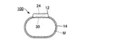
図1は、本発明の第1実施形態に係る血流解析装置100の側面図である。第1実施形態の血流解析装置100は、被験者(生体の例示)の血流に関する生体情報(以下「血流情報」という)を非侵襲的に生成する生体測定機器であり、被験者の身体のうち測定対象となる部位(以下「測定部位」という)Mに装着される。第1実施形態の血流解析装置100は、図1に例示される通り、筐体部12とベルト14とを具備する腕時計型の携帯機器である。すなわち、測定部位Mの例示である手首にベルト14を巻回することで、血流解析装置100は被験者の手首に装着される。第1実施形態の血流情報は、被験者の血流速度(例えば単位時間内に赤血球が動脈内を移動する距離)を血流情報として生成する。<First Embodiment>
FIG. 1 is a side view of a blood
図2は、血流解析装置100の機能に着目した構成図である。図2に例示される通り、第1実施形態の血流解析装置100は、制御装置20と記憶装置22と表示装置24と検出装置30とを具備する。制御装置20および記憶装置22は、筐体部12の内部に設置される。図1に例示される通り、表示装置24(例えば液晶表示パネル)は、例えば筐体部12における測定部位Mとは反対側の表面に設置され、測定結果を含む各種の画像を制御装置20による制御のもとで表示する。 FIG. 2 is a configuration diagram focusing on the function of the blood
図2の検出装置30は、測定部位Mの状態に応じた検出信号Sdを生成する光学センサーモジュールである。図2に例示される通り、第1実施形態の検出装置30は、発光部31と受光部32と駆動回路33と出力回路34とを具備する。発光部31および受光部32は、例えば筐体部12において測定部位Mに対向する位置(典型的には測定部位Mに接触する表面)に設置される。なお、駆動回路33および出力回路34の一方または双方を検出装置30とは別体の外部回路として設置することも可能である。 The
発光部31は、測定部位Mに光を照射する光源である。第1実施形態の発光部31は、狭帯域でコヒーレントなレーザー光を測定部位Mに照射する。例えば共振器内の共振によりレーザー光を出射するVCSEL(Vertical Cavity Surface Emitting LASER)等の発光素子が発光部31として好適に利用される。第1実施形態の発光部31は、例えば近赤外域内の所定の波長λ(λ=800nm〜1300nm)の光を測定部位Mに照射する。図2の駆動回路33は、制御装置20による制御のもとで発光部31を発光させる。なお、相異なる波長の光を出射する複数の発光素子を発光部31として利用することも可能である。また、発光部31が出射する光の波長λは近赤外域に限定されない。 The
発光部31から出射して測定部位Mに入射した光は、測定部位Mの内部で反射および散乱を繰返したうえで筐体部12側に出射して受光部32に到達する。具体的には、測定部位Mの内部に存在する動脈(例えば橈骨動脈または尺骨動脈)等の血管と血管内の血液とを通過した光が受光部32に到達する。受光部32は、測定部位Mから到来する光を受光する。第1実施形態の受光部32は、測定部位Mから到達する光の強度を表す検出信号Saを生成する。例えば、図3に例示される通り、受光強度に応じた電荷を発生するフォトダイオード(PD:Photo Diode)等の受光素子321が受光部32として好適に利用される。検出信号Saは、測定部位Mからの受光強度に応じたアナログの電流信号である。以上の説明から理解される通り、第1実施形態の検出装置30は、発光部31と受光部32とが測定部位Mに対して片側に位置する反射型の光学センサーである。 The light emitted from the
受光部32に到達する光は、測定部位Mの内部において静止する組織(静止組織)で反射した成分と、測定部位Mの内部の動脈内で移動する物体(典型的には赤血球)で反射した成分とを含有する。静止組織での反射の前後において光の周波数は変化しないが、赤血球での反射の前後においては、赤血球の移動速度(すなわち血流速度)に比例した変化量(以下「周波数シフト量」という)Δfだけ光の周波数が変化する。すなわち、測定部位Mを通過して受光部32に到達する光は、発光部31が出射する光の周波数に対して周波数シフト量Δfだけ変動(周波数シフト)した成分を含有する。以上の説明から理解される通り、第1実施形態の検出信号Saは、測定部位Mの内部の血流による周波数シフトが反映された光ビート信号である。 The light reaching the
図2の出力回路34は、受光部32が生成した検出信号Saから検出信号Sdを生成する。検出信号Sdは、受光部32による受光の強度に応じたデジタルの電圧信号である。前述の通り、測定部位Mに照射された光は、測定部位Mの内部の血管および血液を通過してから受光部32に到達する。したがって、検出信号Sdは、被験者の血液を通過した光の強度を表す信号とも換言され得る。 The
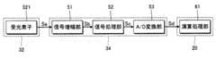
図3は、第1実施形態における受光部32および出力回路34の構成図である。図3に例示される通り、第1実施形態の出力回路34は、信号増幅部51と信号処理部52とA/D変換部53とを含んで構成される。信号増幅部51は、受光部32から供給される検出信号Saを電圧信号に変換するとともに増幅することで検出信号Sbを生成する。例えば、信号増幅部51は、検出信号Saを電圧信号に変換する電流/電圧変換回路と、当該電圧信号を増幅する電圧増幅回路とを含んで構成される。 FIG. 3 is a configuration diagram of the
信号処理部52は、信号増幅部51から供給される検出信号Sb(すなわち、流体を通過した光の強度を表す信号)に対して所定のフィルター処理を実行することで検出信号Scを生成する。信号処理部52が実行するフィルター処理の具体例については後述する。A/D変換部53は、信号処理部52が生成したアナログの検出信号Scを所定のサンプリング周波数Fsでデジタルの検出信号Sdに変換する。以上の説明から理解される通り、検出信号S(Sa,Sb,Sc,Sd)は、測定部位Mの内部の血流による周波数シフトが反映された光ビート信号である。 The
図2の制御装置20は、CPU(Central Processing Unit)またはFPGA(Field-Programmable Gate Array)等の演算処理装置であり、血流解析装置100の全体を制御する。記憶装置22は、例えば不揮発性の半導体メモリーで構成され、制御装置20が実行するプログラムと制御装置20が使用する各種のデータとを記憶する。なお、制御装置20の機能を複数の集積回路に分散した構成、または、制御装置20の一部または全部の機能を専用の電子回路で実現した構成も採用され得る。また、図2では制御装置20と記憶装置22とを別個の要素として図示したが、記憶装置22を内包する制御装置20を例えばASIC(Application Specific Integrated Circuit)等により実現することも可能である。 2 is an arithmetic processing device such as a CPU (Central Processing Unit) or an FPGA (Field-Programmable Gate Array), and controls the entire blood
第1実施形態の制御装置20は、記憶装置22に記憶されたプログラム(アプリケーションプログラム)を実行することで演算処理部61として機能する。演算処理部61は、検出装置30の出力回路34が生成した検出信号Sd(すなわち信号処理部52による処理後の信号)から被験者の血流情報を生成する。第1実施形態の演算処理部61は、前述の通り、測定部位Mの内部の動脈における血流速度を血流情報として算定する。 The
図4は、演算処理部61が血流速度を算定するための処理のフローチャートである。例えば所定の時間毎に図4の処理が実行される。図4の処理を開始すると、演算処理部61は、検出信号Sdから強度スペクトルXを算定する(S1)。強度スペクトルXは、検出信号Sdにおいて周波数軸上の各周波数fに対応する信号成分の強度(パワーまたは振幅)P(f)の分布である。強度スペクトルXの算定には、離散フーリエ変換等の公知の周波数解析が任意に採用され得る。 FIG. 4 is a flowchart of processing for the
演算処理部61は、検出信号Sdの強度スペクトルXから血流速度V(血流情報)を算定する(S2)。具体的には、第1実施形態の演算処理部61は、以下の数式(1)の演算により血流量Q(すなわち単位時間内に動脈内を移動する血液の体積)を算定し、測定部位Mの血管について別途に推定された断面積Aにより血流量Qを除算することで血流速度V(V=Q/A)を算定する。なお、相異なる時点について算定された複数の血流速度Vの平均値を血流情報として演算処理部61が生成することも可能である。
数式(1)は、検出信号Sdの各周波数fと当該周波数fにおける強度P(f)とから血流量Qを算定するための演算式である。数式(1)の記号K1は所定の比例定数であり、記号<I2>は、検出信号Sdの全帯域にわたるパワーである。The
Expression (1) is an arithmetic expression for calculating the blood flow rate Q from each frequency f of the detection signal Sd and the intensity P (f) at the frequency f. The symbol K1 in the equation (1) is a predetermined proportionality constant, and the symbol <I2 > is the power over the entire band of the detection signal Sd.
数式(1)から理解される通り、第1実施形態の演算処理部61は、強度スペクトルXにおける各周波数fの強度P(f)と当該周波数fとの積(f×P(f))を所定の範囲(以下「演算範囲」という)について積算することで血流量Qを算定する。強度スペクトルXの強度P(f)と周波数fとの積(f×P(f))は、周波数fにより重み付けされた強度(以下「加重強度」という)を意味する。演算範囲は、加重強度の積分範囲に相当し、周波数軸上の所定の周波数(以下「下端周波数」という)f1と、下端周波数f1を上回る所定の周波数(以下「上端周波数」という)f2との間の範囲である。下端周波数f1は第1周波数の例示であり、上端周波数f2は第2周波数の例示である。以上の説明から理解される通り、第1実施形態の演算処理部61は、検出装置30が生成した検出信号Sdの強度スペクトルXから血流情報(血流速度V)を生成する。図2の表示装置24は、演算処理部61が生成した血流情報(血流速度V)を表示する。 As understood from the mathematical expression (1), the
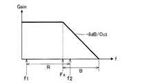
図5は、第1実施形態の信号処理部52が実行するフィルター処理の説明図である。具体的には、信号処理部52が実行するフィルター処理の周波数特性(すなわち、周波数領域におけるゲインの分布)が図5には例示されている。図5から理解される通り、第1実施形態の信号処理部52は、所定の周波数帯域(以下「処理帯域」という)B内で周波数が高い成分ほど抑制されるようにフィルター処理を実行する。例えばローパスフィルターまたはバンドパスフィルターが信号処理部52として好適に利用される。具体的には、1次のアナログフィルター回路の所定個(単数または複数)を組合せることで信号処理部52が構成される。 FIG. 5 is an explanatory diagram of the filter processing executed by the
処理帯域Bは、信号処理部52による検出信号Sbの抑制の度合(すなわち、フィルター処理の周波数特性)が6dB/Oct(オクターブ)以上となる範囲であり、所定の周波数Fxに対して高周波側の範囲である。すなわち、処理帯域B内では、検出信号Sを構成する各周波数fの成分が、周波数fに比例した度合(6dB/Oct)以上の度合で抑制される。例えば、処理帯域B内でフィルター処理の周波数特性が6dB/Octに設定された場合を想定すると、処理帯域B内の特定の周波数m×f(mは自然数)でのゲインは、処理帯域B内の周波数fでのゲインの1/mに設定される。周波数Fxは、検出信号Sbの抑制の度合が6dB/Oct以上となる範囲(すなわち処理帯域B)の下端に相当する。 The processing band B is a range in which the degree of suppression of the detection signal Sb by the signal processing unit 52 (that is, the frequency characteristic of the filter processing) is 6 dB / Oct (octave) or more, and is higher than the predetermined frequency Fx. It is a range. That is, in the processing band B, the component of each frequency f that constitutes the detection signal S is suppressed to a degree that is proportional to the frequency f (6 dB / Oct) or more. For example, assuming that the frequency characteristic of filter processing is set to 6 dB / Oct within the processing band B, the gain at a specific frequency m × f (m is a natural number) within the processing band B is within the processing band B. 1 / m of the gain at the frequency f. The frequency Fx corresponds to the lower end of a range in which the degree of suppression of the detection signal Sb is 6 dB / Oct or higher (that is, the processing band B).
図5に例示される通り、血流量Qの算定に適用される演算範囲Rと信号処理部52によるフィルター処理の処理帯域Bとは、部分的に相互に重複する。具体的には、演算範囲Rにおける高周波側の部分と処理帯域Bにおける低周波側の部分とが相互に重複する。すなわち、処理帯域Bの下端の周波数Fxは、演算範囲Rの下端周波数f1を上回り、かつ、演算範囲Rの上端周波数f2以下である。図5においては、処理帯域Bの下端の周波数Fxが演算範囲Rの上端周波数f2を下回る場合が例示されている。 As illustrated in FIG. 5, the calculation range R applied to the calculation of the blood flow rate Q and the processing band B of the filter processing by the
ここで、上端周波数f2は、A/D変換部53のナイキスト周波数(Fs/2)以下である必要がある。すなわち、演算範囲Rの上端周波数f2は、処理帯域Bの下端の周波数FxとA/D変換部53のナイキスト周波数(Fs/2)との間の数値に設定される(Fx≦f2≦Fs/2)。例えば、処理帯域Bの周波数Fxが45kHzであり、A/D変換部53が100kHzのサンプリング周波数Fsで動作する構成を想定すると、上端周波数f2は、45kHz(=Fx)以上かつ50kHz(=Fs/2)以下の範囲内の適切な数値(例えば50kHz)に設定される。他方、下端周波数f1は、上端周波数f2と比較して充分に小さい数値(例えば200Hz程度)に設定される。以上の説明から理解される通り、第1実施形態の演算処理部61は、信号処理部52によるフィルター処理で抑制される処理帯域Bの一部を含む演算範囲Rについて加重強度(f×P(f))を積算することで血流量Qを算定する。 Here, the upper end frequency f2 needs to be equal to or lower than the Nyquist frequency (Fs / 2) of the A /
図6には、検出信号Sdの強度スペクトルXが図示されている。受光部32や出力回路34等の回路要素に起因して不可避的に発生するショットノイズが検出信号Sdには含有される。ショットノイズは、周波数fの広い範囲にわたり均等に分布するホワイトノイズである。他方、測定部位Mを通過した光(すなわち本来の解析対象)に由来する信号成分の強度は、高周波側ほど低いという傾向がある。したがって、図6から理解される通り、強度スペクトルXのうち高周波側の周波数帯域Nでは、測定部位Mを通過した光に対してショットノイズの影響が支配的となる。ショットノイズの影響が支配的となる周波数帯域Nの下端の周波数(以下「高ノイズ周波数」という)Fnは、測定部位Mにおける血管または血液の状態に応じて変動し得る。 FIG. 6 shows the intensity spectrum X of the detection signal Sd. Shot noise that inevitably occurs due to circuit elements such as the
図7および図8は、周波数軸上における加重強度(f×P(f))の分布である。図7は、信号処理部52によるフィルター処理を省略した構成(以下「対比例」という)における加重強度の分布である。図8は、処理帯域B内の信号成分を抑制するフィルター処理を信号処理部52が実行する第1実施形態における加重強度の分布である。 7 and 8 are distributions of weighted intensity (f × P (f)) on the frequency axis. FIG. 7 shows a distribution of weighted intensity in a configuration (hereinafter referred to as “proportional”) in which the filter processing by the
いま、数式(1)の演算により血流量Qを高精度に測定するという観点からは、演算範囲Rを広く確保する必要がある。すなわち、上端周波数f2を高目に設定することが要求される。他方、強度スペクトルXの強度P(f)に対する周波数fの乗算により、対比例では、図7から理解される通り、強度スペクトルXにおける高周波側のショットノイズが強調される。したがって、上端周波数f2を高目に設定した構成では、演算範囲Rの高周波側においてショットノイズが支配的となり、結果的に血流量Qの高精度な測定が阻害される。以上の問題を解決するために、上端周波数f2を低目に設定した場合には、演算範囲Rが過度に狭くなる結果、血流量Qの測定の精度が却って低下する可能性がある。以上の説明から理解される通り、血流量Qを常に高精度に測定するためには、測定部位Mにおける血管または血液の状態に応じて上端周波数f2を変化させる必要がある。例えば、高ノイズ周波数Fnが高い状況では上端周波数f2を高目に設定し、高ノイズ周波数Fnが低い状況では上端周波数f2を低目に設定するといった具合である。 Now, it is necessary to ensure a wide calculation range R from the viewpoint of measuring the blood flow rate Q with high accuracy by the calculation of Equation (1). That is, it is required to set the upper end frequency f2 to a high value. On the other hand, by multiplying the intensity P (f) of the intensity spectrum X by the frequency f, the shot noise on the high frequency side in the intensity spectrum X is emphasized in a comparative manner as understood from FIG. Therefore, in the configuration in which the upper end frequency f2 is set to a high value, shot noise becomes dominant on the high frequency side of the calculation range R, and as a result, highly accurate measurement of the blood flow rate Q is hindered. In order to solve the above problem, when the upper end frequency f2 is set to a low value, the calculation range R becomes excessively narrow, and as a result, the measurement accuracy of the blood flow rate Q may be lowered. As understood from the above description, in order to always measure the blood flow rate Q with high accuracy, it is necessary to change the upper end frequency f2 according to the state of the blood vessel or blood at the measurement site M. For example, when the high noise frequency Fn is high, the upper end frequency f2 is set high, and when the high noise frequency Fn is low, the upper end frequency f2 is set low.
以上に説明した対比例とは対照的に、第1実施形態では、検出信号Sbのうち演算範囲Rに部分的に重複する処理帯域B内の信号成分がフィルター処理により抑制される。すなわち、図8から理解される通り、上端周波数f2の高低に関わらず、演算範囲R内については、強度P(f)に対する周波数fの乗算により強調されるべきショットノイズの影響がフィルター処理で低減される。したがって、例えば演算範囲Rが充分に確保されるように上端周波数f2を高目に設定した構成でも、検出信号Sbのショットノイズの影響を低減して血流量Qを高精度に測定することが可能である。また、測定部位Mにおける血管または血液の状態に応じて上端周波数f2を変化させる前述の処理が不要であるから、血流情報の生成のための負荷が低減されるという利点もある。 In contrast to the comparison described above, in the first embodiment, signal components in the processing band B that partially overlap the calculation range R in the detection signal Sb are suppressed by the filter processing. That is, as understood from FIG. 8, regardless of the level of the upper end frequency f2, within the calculation range R, the influence of shot noise that should be emphasized by multiplying the intensity P (f) by the frequency f is reduced by filtering. Is done. Therefore, for example, even when the upper end frequency f2 is set high so that the calculation range R is sufficiently secured, the influence of shot noise on the detection signal Sb can be reduced and the blood flow Q can be measured with high accuracy. It is. Further, since the above-described processing for changing the upper end frequency f2 according to the state of the blood vessel or blood at the measurement site M is not necessary, there is an advantage that the load for generating blood flow information is reduced.
次に、演算範囲Rと処理帯域Bとが部分的に相互に重複する前述の状況で成立する条件について説明する。いま、血流解析装置100が測定可能な仕様上の血流速度Vの範囲が最小値V1から最大値V2までの範囲である場合を想定する。前述の通り、血液中の赤血球での光反射に起因した周波数シフト量Δfは血流速度Vに比例する。具体的には、周波数シフト量Δfは以下の数式(2)で表現される。
数式(2)の記号λは発光部31が測定部位Mに照射する光の波長であり、記号θは、発光部31から測定部位Mに入射する光の入射角である。実際の血流解析装置100を想定すると、波長λは発光部31が出射する光の波長として既知であり、入射角θは測定部位Mの表面に対する発光部31の光軸の角度から確定される。また、記号nは測定部位M(特に動脈および血液)の屈折率であり、概略的には1.33〜1.34の範囲内の既知の数値である。血流解析装置100による測定が想定される血流速度Vの最大値V2を以上の各定数(λ,θ,n)とともに数式(2)に代入すると、血流解析装置100が測定可能な範囲内で最大の周波数シフト量Δf2を得ることができる。Next, conditions that are satisfied in the above-described situation in which the calculation range R and the processing band B partially overlap each other will be described. Assume that the range of the blood flow velocity V on the specification that can be measured by the
The symbol λ in Equation (2) is the wavelength of light that the
なお、血流速度Vの最大値V2は、超音波を利用した流速計により測定することができる。また、動脈の血流を測定する場合には、例えば、血流速度Vの最大値V2は0.8m/sec以上かつ1.2m/sec以下であり、毛細血管の血流を測定する場合には、例えば、血流速度Vの最大値V2は2mm/sec以上かつ12mm/sec以下であることが知られている。 Note that the maximum value V2 of the blood flow velocity V can be measured with a flowmeter using ultrasonic waves. When measuring the blood flow in the artery, for example, the maximum value V2 of the blood flow velocity V is 0.8 m / sec or more and 1.2 m / sec or less. For example, it is known that the maximum value V2 of the blood flow velocity V is 2 mm / sec or more and 12 mm / sec or less.
次に、処理帯域Bの下端周波数Fxを決定する方法を説明する。図9は、処理帯域Bの下端周波数Fxを特定する方法を説明するための図である。図9に例示される通り、スペクトラムアナライザーSAの端子Iから例えば正弦波の入力信号を信号処理部52に入力し、信号処理部52からの電力または電圧を出力信号として端子Aに入力する。ここで、入力信号の周波数を変化させ、各周波数に対する出力信号を取得することで、図5から図8に例示したような周波数特性を得ることができる。処理帯域Bの下端周波数Fxは、入力信号の周波数が高くなるにしたがって出力信号が低下する周波数である。具体的には、図10に示すように、入力信号の周波数が高くなるにしたがって出力信号が3dBだけ低下する周波数を処理帯域Bの下端周波数Fxとする。なお、図9では、信号処理部52の入力信号と出力信号との関係から周波数特性を得る場合を例示したが、信号増幅部51に入力信号を入力してもよいし、信号処理部52よりも後段の要素(例えばA/D変換部53)から出力信号を取得してもよい。 Next, a method for determining the lower end frequency Fx of the processing band B will be described. FIG. 9 is a diagram for explaining a method of specifying the lower end frequency Fx of the processing band B. As illustrated in FIG. 9, for example, a sine wave input signal is input to the
また、より多くの血流情報を得るには、血流速度Vの最大値V2までの血流情報を得ることが望ましい。換言すると、上端周波数f2が周波数シフト量Δf2以上である(f2≧Δf2)ことが望ましい。この場合、周波数シフト量Δf2が周波数Fxを上回るという関係(Fx<Δf2)が確認できれば、上端周波数f2が周波数シフト量Δf2以上である(Δf2≦f2)ので、上端周波数f2が周波数Fxを上回る(Fx<f2)。上端周波数f2が周波数Fxを上回る(Fx<f2)ということは、演算範囲Rと処理帯域Bとが部分的に重複するという条件が成立していることになる。 In order to obtain more blood flow information, it is desirable to obtain blood flow information up to the maximum value V2 of the blood flow velocity V. In other words, it is desirable that the upper end frequency f2 is equal to or greater than the frequency shift amount Δf2 (f2 ≧ Δf2). In this case, if the relationship that the frequency shift amount Δf2 exceeds the frequency Fx (Fx <Δf2) can be confirmed, the upper end frequency f2 is greater than or equal to the frequency shift amount Δf2 (Δf2 ≦ f2), so the upper end frequency f2 exceeds the frequency Fx ( Fx <f2). When the upper end frequency f2 exceeds the frequency Fx (Fx <f2), the condition that the calculation range R and the processing band B partially overlap is satisfied.
<第2実施形態>
本発明の第2実施形態を説明する。なお、以下に例示する各形態において作用または機能が第1実施形態と同様である要素については、第1実施形態の説明で使用した符号を流用して各々の詳細な説明を適宜に省略する。Second Embodiment
A second embodiment of the present invention will be described. In addition, about the element which an effect | action or function is the same as that of 1st Embodiment in each form illustrated below, the code | symbol used by description of 1st Embodiment is diverted, and each detailed description is abbreviate | omitted suitably.
図11は、第2実施形態における受光部32および出力回路34の構成図である。図11に例示される通り、第2実施形態の受光部32は、相異なる位置に配置された受光素子321と受光素子322とを含んで構成される。受光素子321は、測定部位Mからの受光強度に応じた検出信号Sa1を生成し、受光素子322は、測定部位Mからの受光強度に応じた検出信号Sa2を生成する。 FIG. 11 is a configuration diagram of the
第2実施形態の信号増幅部51は、受光素子321が生成した検出信号Sa1と受光素子322が生成した検出信号Sa2との差分に相当する検出信号Sbを生成する。したがって、検出信号Sa1と検出信号Sa2とに共通に含まれる定常的なノイズを低減した検出信号Sbが生成される。例えば差動増幅回路が信号増幅部51として好適に利用される。信号処理部52は、信号増幅部51から供給される検出信号Sbに対して第1実施形態と同様のフィルター処理を実行する。他の要素の機能および作用は第1実施形態と同様である。 The
第2実施形態においても第1実施形態と同様の効果が実現される。また、第2実施形態では、受光素子321が生成した検出信号Sa1と受光素子322が生成した検出信号Sa2との差分に相当する検出信号Sbが生成される。すなわち、検出信号Sa1と検出信号Sa2とに共通に含まれるノイズを低減したSN比が高い検出信号Sbが生成される。したがって、血流情報を高精度に生成できるという効果は格別に顕著である。 In the second embodiment, the same effect as in the first embodiment is realized. In the second embodiment, the detection signal Sb corresponding to the difference between the detection signal Sa1 generated by the
<変形例>
以上に例示した各形態は多様に変形され得る。具体的な変形の態様を以下に例示する。以下の例示から任意に選択された2以上の態様を適宜に併合することも可能である。<Modification>
Each form illustrated above can be variously modified. Specific modifications are exemplified below. Two or more modes arbitrarily selected from the following examples can be appropriately combined.
(1)相互に別体で構成された複数の機器により血流解析装置100を実現することも可能である。例えば、前述の各形態で例示した演算処理部61を、携帯電話機またはスマートフォン等の汎用の情報端末により実現することも可能である。また、演算処理部61が生成した血流情報を、情報端末が具備する表示装置24に表示させる構成も採用され得る。(1) The blood
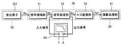
(2)出力回路34を構成する複数の要素の順序は前述の各形態の例示に限定されない。例えば、前述の各形態では、信号処理部52が生成した検出信号ScをA/D変換部53がA/D変換したが、例えば図12に例示される通り、信号処理部52とA/D変換部53との順序を逆転することも可能である。図12の構成では、信号増幅部51が増幅した検出信号SbをA/D変換部53がアナログからデジタルに変換し、変換後の検出信号Scに対するフィルター処理で信号処理部52が検出信号Sdを生成する。したがって、検出信号Scのうち処理帯域B内の成分を抑制するデジタルフィルターが信号処理部52として利用される。また、制御装置20がプログラムを実行することで信号処理部52を実現することも可能である。(2) The order of the plurality of elements constituting the
(3)前述の各形態では、血流速度Vを血流情報として例示したが、血液の速度に関する情報(血流情報)の種類は以上の例示に限定されない。例えば、前述の数式(1)で算定される血流量Qを血流情報として被験者に提示することも可能である。また、血流量Qおよび血流速度V等の血流情報から他の生体情報を生成することも可能である。例えば、血圧、酸素飽和度(SpO2)または血管年齢(血管の硬さ)等の各種の生体情報が、血流量Qおよび血流速度V等の血管情報から推定され得る。(3) In each of the above-described embodiments, the blood flow velocity V is exemplified as the blood flow information. However, the type of information related to the blood velocity (blood flow information) is not limited to the above examples. For example, it is possible to present the blood flow volume Q calculated by the above formula (1) to the subject as blood flow information. It is also possible to generate other biological information from blood flow information such as blood flow volume Q and blood flow velocity V. For example, various types of biological information such as blood pressure, oxygen saturation (SpO2), or blood vessel age (blood vessel hardness) can be estimated from blood vessel information such as blood flow volume Q and blood flow velocity V.
(4)前述の形態では、筐体部12とベルト14とから構成される腕時計型の血流解析装置100を例示したが、血流解析装置の具体的な形態は任意である。例えば、被験者の身体に貼付可能なパッチ型、被験者の耳介に装着可能なイヤリング型、被験者の指先に装着可能な指装着型(例えば着爪型)、または、被験者の頭部に装着可能なヘッドマウント型など、任意の形態の血流解析装置100が採用され得る。(4) In the above-described embodiment, the wristwatch-type blood
(5)前述の各形態では、被験者の血流を解析する血流解析装置100を例示したが、本発明が適用される範囲は血流の解析に限定されない。例えば、血液以外の各種の液体(例えば管内を流動する薬液)の流動を解析する装置にも本発明を適用することが可能である。以上の説明から理解される通り、本発明の好適な態様は、流体を解析する装置(流体解析装置)であり、前述の各形態で説明した血流解析装置100は、本発明の好適な態様に係る流体解析装置の例示である。(5) In each of the above-described embodiments, the blood
100…血流解析装置、12…筐体部、14…ベルト、20…制御装置、22…記憶装置、24…表示装置、30…検出装置、31…発光部、32…受光部、321,322…受光素子、33…駆動回路、34…出力回路、51…信号増幅部、52…信号処理部、53…A/D変換部、61…演算処理部。DESCRIPTION OF
Claims (6)
Translated fromJapanese前記フィルター処理後の信号の強度スペクトルから、前記流体の速度に関する情報を生成する演算処理部と
を具備する流体解析装置。A signal processing unit that performs a filtering process on a detection signal that represents the intensity of light that has passed through the fluid so that a component having a higher frequency within a predetermined processing band is suppressed;
A fluid analysis apparatus comprising: an arithmetic processing unit that generates information on the velocity of the fluid from the intensity spectrum of the signal after the filter processing.
前記処理帯域と前記演算範囲とは部分的に相互に重複する
請求項1の流体解析装置。The calculation processing unit generates information on the fluid velocity by integrating the product of the intensity of each frequency in the intensity spectrum and the frequency for a predetermined calculation range,
The fluid analysis apparatus according to claim 1, wherein the processing band and the calculation range partially overlap each other.
前記処理帯域の下端の周波数は、前記第2周波数を下回る
請求項2の流体解析装置。The calculation range is a range between a first frequency and a second frequency exceeding the first frequency,
The fluid analysis device according to claim 2, wherein a frequency at a lower end of the processing band is lower than the second frequency.
請求項1から請求項3の何れかの流体解析装置。The fluid analysis device according to any one of claims 1 to 3, wherein the processing band is a range in which suppression of the detection signal by the signal processing unit is 6 dB / Oct or more.
前記フィルター処理後の信号の強度スペクトルから前記血管内の血液の速度に関する情報を生成する演算処理部と
を具備する血流解析装置。A signal processing unit that performs a filtering process so that a component having a higher frequency within a predetermined processing band is suppressed with respect to a detection signal representing the intensity of light that has passed through the blood vessel,
A blood flow analysis apparatus comprising: an arithmetic processing unit that generates information related to the blood velocity in the blood vessel from the intensity spectrum of the signal after the filter processing.
前記フィルター処理後の信号の強度スペクトルから前記血管内の血液の速度に関する情報を生成する
流体解析方法。For the detection signal that represents the intensity of light that has passed through the blood vessel, filter processing is performed so that the higher the frequency within the predetermined processing band, the more the component is suppressed.
A fluid analysis method for generating information relating to the blood velocity in the blood vessel from the intensity spectrum of the signal after the filtering.
Priority Applications (2)
| Application Number | Priority Date | Filing Date | Title |
|---|---|---|---|
| JP2017086625AJP7019962B2 (en) | 2017-04-25 | 2017-04-25 | Fluid analysis device, blood flow analysis device and fluid analysis method |
| US15/945,882US20180303429A1 (en) | 2017-04-25 | 2018-04-05 | Blood flow analyzer, blood flow analysis method, and program |
Applications Claiming Priority (1)
| Application Number | Priority Date | Filing Date | Title |
|---|---|---|---|
| JP2017086625AJP7019962B2 (en) | 2017-04-25 | 2017-04-25 | Fluid analysis device, blood flow analysis device and fluid analysis method |
Publications (2)
| Publication Number | Publication Date |
|---|---|
| JP2018183375Atrue JP2018183375A (en) | 2018-11-22 |
| JP7019962B2 JP7019962B2 (en) | 2022-02-16 |
Family
ID=64356370
Family Applications (1)
| Application Number | Title | Priority Date | Filing Date |
|---|---|---|---|
| JP2017086625AActiveJP7019962B2 (en) | 2017-04-25 | 2017-04-25 | Fluid analysis device, blood flow analysis device and fluid analysis method |
Country Status (1)
| Country | Link |
|---|---|
| JP (1) | JP7019962B2 (en) |
Cited By (1)
| Publication number | Priority date | Publication date | Assignee | Title |
|---|---|---|---|---|
| JP7589284B2 (en) | 2019-02-11 | 2024-11-25 | コー・ヤング・テクノロジー・インコーポレーテッド | Blood flow measuring device and blood flow measuring method |
Citations (10)
| Publication number | Priority date | Publication date | Assignee | Title |
|---|---|---|---|---|
| US6173197B1 (en)* | 1996-11-09 | 2001-01-09 | Moor Instruments Limited | Apparatus for measuring microvascular blood flow |
| US20050203416A1 (en)* | 2004-03-10 | 2005-09-15 | Angelsen Bjorn A. | Extended, ultrasound real time 2D imaging probe for insertion into the body |
| JP2005287820A (en)* | 2004-03-31 | 2005-10-20 | U-Medica Inc | Biological phenomenon measurement recording apparatus and noise component removal method |
| US20080188721A1 (en)* | 2007-02-07 | 2008-08-07 | Cardiac Pacemakers, Inc. | Method and apparatus for implantably acquiring a wideband signal |
| JP2012210321A (en)* | 2011-03-31 | 2012-11-01 | Pioneer Electronic Corp | Light detection device and fluid measuring device |
| JP2013099388A (en)* | 2011-11-07 | 2013-05-23 | Toshiba Corp | Ultrasonic diagnostic equipment, and control program |
| JP2014079428A (en)* | 2012-10-17 | 2014-05-08 | Omega Wave Kk | Blood flow rate measuring apparatus |
| WO2015198470A1 (en)* | 2014-06-27 | 2015-12-30 | パイオニア株式会社 | Measurement device and measurement method |
| US20170105634A1 (en)* | 2015-10-20 | 2017-04-20 | Denso Corporation | Pulse Wave Signal Processor |
| JP2018068428A (en)* | 2016-10-25 | 2018-05-10 | ソニー株式会社 | Information processing device, information processing method, and program |
- 2017
- 2017-04-25JPJP2017086625Apatent/JP7019962B2/enactiveActive
Patent Citations (10)
| Publication number | Priority date | Publication date | Assignee | Title |
|---|---|---|---|---|
| US6173197B1 (en)* | 1996-11-09 | 2001-01-09 | Moor Instruments Limited | Apparatus for measuring microvascular blood flow |
| US20050203416A1 (en)* | 2004-03-10 | 2005-09-15 | Angelsen Bjorn A. | Extended, ultrasound real time 2D imaging probe for insertion into the body |
| JP2005287820A (en)* | 2004-03-31 | 2005-10-20 | U-Medica Inc | Biological phenomenon measurement recording apparatus and noise component removal method |
| US20080188721A1 (en)* | 2007-02-07 | 2008-08-07 | Cardiac Pacemakers, Inc. | Method and apparatus for implantably acquiring a wideband signal |
| JP2012210321A (en)* | 2011-03-31 | 2012-11-01 | Pioneer Electronic Corp | Light detection device and fluid measuring device |
| JP2013099388A (en)* | 2011-11-07 | 2013-05-23 | Toshiba Corp | Ultrasonic diagnostic equipment, and control program |
| JP2014079428A (en)* | 2012-10-17 | 2014-05-08 | Omega Wave Kk | Blood flow rate measuring apparatus |
| WO2015198470A1 (en)* | 2014-06-27 | 2015-12-30 | パイオニア株式会社 | Measurement device and measurement method |
| US20170105634A1 (en)* | 2015-10-20 | 2017-04-20 | Denso Corporation | Pulse Wave Signal Processor |
| JP2018068428A (en)* | 2016-10-25 | 2018-05-10 | ソニー株式会社 | Information processing device, information processing method, and program |
Cited By (2)
| Publication number | Priority date | Publication date | Assignee | Title |
|---|---|---|---|---|
| JP7589284B2 (en) | 2019-02-11 | 2024-11-25 | コー・ヤング・テクノロジー・インコーポレーテッド | Blood flow measuring device and blood flow measuring method |
| US12193802B2 (en) | 2019-02-11 | 2025-01-14 | Koh Young Technology Inc. | Blood flow measurement device and blood flow measurement method |
Also Published As
| Publication number | Publication date |
|---|---|
| JP7019962B2 (en) | 2022-02-16 |
Similar Documents
| Publication | Publication Date | Title |
|---|---|---|
| JP6597410B2 (en) | Biological information measuring device and biological information measuring method | |
| US20190053767A1 (en) | Biological analysis device, biological analysis method, and program | |
| JP6750367B2 (en) | Blood pressure measuring device and blood pressure measuring method | |
| EP3315062B1 (en) | Bio-signal quality assessment apparatus and method and bio-signal measurement parameter optimization apparatus and method | |
| JP2018519889A (en) | Photoelectric volume pulse wave recording device | |
| JPWO2015033469A1 (en) | Flow velocity detection apparatus and flow velocity detection method | |
| Norgia et al. | Low-cost optical flowmeter with analog front-end electronics for blood extracorporeal circulators | |
| US10058273B2 (en) | Detection device and measuring apparatus | |
| JP2018029870A (en) | Detection apparatus and detection method | |
| JP7019962B2 (en) | Fluid analysis device, blood flow analysis device and fluid analysis method | |
| US20180303429A1 (en) | Blood flow analyzer, blood flow analysis method, and program | |
| JP2019187637A (en) | Living body analysis apparatus, living body analysis method, and program | |
| JP6996224B2 (en) | Blood flow analyzer, blood flow analysis method and program | |
| JP2019076641A (en) | Measurement device and measurement method | |
| JP7039925B2 (en) | Bioanalyzer | |
| JPH11287859A (en) | Laser range finder | |
| US11832972B2 (en) | Biological analysis device, biological analysis method, and program | |
| EP4220187A1 (en) | Measuring device, measuring system, measuring method, and program | |
| JP7124460B2 (en) | Biological analysis device, biological analysis method and program | |
| JP2019033900A (en) | Organism analyzer, organism analysis method and program | |
| JP2022085336A (en) | Measuring equipment, measuring system, measuring method, program and calibration method of measuring equipment | |
| JP2019033902A (en) | Biological analysis apparatus, biological analysis method, and program | |
| JP6996157B2 (en) | Bioanalyzers, bioanalysis methods and programs | |
| JP7187824B2 (en) | Biological analysis device, biological analysis method and program | |
| JP7010002B2 (en) | Pulse wave analyzer, pulse wave analysis method and program |
Legal Events
| Date | Code | Title | Description |
|---|---|---|---|
| A621 | Written request for application examination | Free format text:JAPANESE INTERMEDIATE CODE: A621 Effective date:20200323 | |
| A977 | Report on retrieval | Free format text:JAPANESE INTERMEDIATE CODE: A971007 Effective date:20210126 | |
| A131 | Notification of reasons for refusal | Free format text:JAPANESE INTERMEDIATE CODE: A131 Effective date:20210209 | |
| A521 | Request for written amendment filed | Free format text:JAPANESE INTERMEDIATE CODE: A523 Effective date:20210408 | |
| A131 | Notification of reasons for refusal | Free format text:JAPANESE INTERMEDIATE CODE: A131 Effective date:20210907 | |
| A521 | Request for written amendment filed | Free format text:JAPANESE INTERMEDIATE CODE: A523 Effective date:20210929 | |
| TRDD | Decision of grant or rejection written | ||
| A01 | Written decision to grant a patent or to grant a registration (utility model) | Free format text:JAPANESE INTERMEDIATE CODE: A01 Effective date:20220104 | |
| A61 | First payment of annual fees (during grant procedure) | Free format text:JAPANESE INTERMEDIATE CODE: A61 Effective date:20220117 | |
| R150 | Certificate of patent or registration of utility model | Ref document number:7019962 Country of ref document:JP Free format text:JAPANESE INTERMEDIATE CODE: R150 |