JP2018176326A - Teaching device, display device, teaching program and display program - Google Patents
Teaching device, display device, teaching program and display programDownload PDFInfo
- Publication number
- JP2018176326A JP2018176326AJP2017077167AJP2017077167AJP2018176326AJP 2018176326 AJP2018176326 AJP 2018176326AJP 2017077167 AJP2017077167 AJP 2017077167AJP 2017077167 AJP2017077167 AJP 2017077167AJP 2018176326 AJP2018176326 AJP 2018176326A
- Authority
- JP
- Japan
- Prior art keywords
- hand
- work
- hand work
- teaching
- robot
- Prior art date
- Legal status (The legal status is an assumption and is not a legal conclusion. Google has not performed a legal analysis and makes no representation as to the accuracy of the status listed.)
- Granted
Links
- 238000000034methodMethods0.000claimsabstractdescription83
- 230000008569processEffects0.000claimsabstractdescription72
- 230000008859changeEffects0.000claimsabstractdescription24
- 238000010586diagramMethods0.000claimsdescription26
- 230000008602contractionEffects0.000claimsdescription8
- 230000007246mechanismEffects0.000description18
- 230000036544postureEffects0.000description14
- 239000012636effectorSubstances0.000description9
- 238000004891communicationMethods0.000description7
- 210000000707wristAnatomy0.000description6
- 238000009434installationMethods0.000description2
- 230000004048modificationEffects0.000description2
- 238000012986modificationMethods0.000description2
- 235000001543Corylus americanaNutrition0.000description1
- 240000007582Corylus avellanaSpecies0.000description1
- 235000007466Corylus avellanaNutrition0.000description1
- 240000003473Grevillea banksiiSpecies0.000description1
- 238000005452bendingMethods0.000description1
- 230000007423decreaseEffects0.000description1
- 238000006073displacement reactionMethods0.000description1
- 230000000694effectsEffects0.000description1
- 238000004519manufacturing processMethods0.000description1
- 239000011159matrix materialSubstances0.000description1
- 230000000474nursing effectEffects0.000description1
- 230000004044responseEffects0.000description1
- 230000009466transformationEffects0.000description1
Images


Classifications
- B—PERFORMING OPERATIONS; TRANSPORTING
- B25—HAND TOOLS; PORTABLE POWER-DRIVEN TOOLS; MANIPULATORS
- B25J—MANIPULATORS; CHAMBERS PROVIDED WITH MANIPULATION DEVICES
- B25J9/00—Programme-controlled manipulators
- B25J9/16—Programme controls
- B25J9/1656—Programme controls characterised by programming, planning systems for manipulators
- B25J9/1671—Programme controls characterised by programming, planning systems for manipulators characterised by simulation, either to verify existing program or to create and verify new program, CAD/CAM oriented, graphic oriented programming systems
- B—PERFORMING OPERATIONS; TRANSPORTING
- B25—HAND TOOLS; PORTABLE POWER-DRIVEN TOOLS; MANIPULATORS
- B25J—MANIPULATORS; CHAMBERS PROVIDED WITH MANIPULATION DEVICES
- B25J9/00—Programme-controlled manipulators
- B25J9/16—Programme controls
- B25J9/1628—Programme controls characterised by the control loop
- B25J9/163—Programme controls characterised by the control loop learning, adaptive, model based, rule based expert control
- G—PHYSICS
- G05—CONTROLLING; REGULATING
- G05B—CONTROL OR REGULATING SYSTEMS IN GENERAL; FUNCTIONAL ELEMENTS OF SUCH SYSTEMS; MONITORING OR TESTING ARRANGEMENTS FOR SUCH SYSTEMS OR ELEMENTS
- G05B19/00—Programme-control systems
- G05B19/02—Programme-control systems electric
- G05B19/42—Recording and playback systems, i.e. in which the programme is recorded from a cycle of operations, e.g. the cycle of operations being manually controlled, after which this record is played back on the same machine
- G05B19/425—Teaching successive positions by numerical control, i.e. commands being entered to control the positioning servo of the tool head or end effector
- B—PERFORMING OPERATIONS; TRANSPORTING
- B25—HAND TOOLS; PORTABLE POWER-DRIVEN TOOLS; MANIPULATORS
- B25J—MANIPULATORS; CHAMBERS PROVIDED WITH MANIPULATION DEVICES
- B25J13/00—Controls for manipulators
- G—PHYSICS
- G05—CONTROLLING; REGULATING
- G05B—CONTROL OR REGULATING SYSTEMS IN GENERAL; FUNCTIONAL ELEMENTS OF SUCH SYSTEMS; MONITORING OR TESTING ARRANGEMENTS FOR SUCH SYSTEMS OR ELEMENTS
- G05B2219/00—Program-control systems
- G05B2219/30—Nc systems
- G05B2219/36—Nc in input of data, input key till input tape
- G05B2219/36177—Select block and display graphic representation associated with block type
- Y—GENERAL TAGGING OF NEW TECHNOLOGICAL DEVELOPMENTS; GENERAL TAGGING OF CROSS-SECTIONAL TECHNOLOGIES SPANNING OVER SEVERAL SECTIONS OF THE IPC; TECHNICAL SUBJECTS COVERED BY FORMER USPC CROSS-REFERENCE ART COLLECTIONS [XRACs] AND DIGESTS
- Y10—TECHNICAL SUBJECTS COVERED BY FORMER USPC
- Y10S—TECHNICAL SUBJECTS COVERED BY FORMER USPC CROSS-REFERENCE ART COLLECTIONS [XRACs] AND DIGESTS
- Y10S901/00—Robots
- Y10S901/02—Arm motion controller
- Y10S901/03—Teaching system
Landscapes
- Engineering & Computer Science (AREA)
- Robotics (AREA)
- Mechanical Engineering (AREA)
- Physics & Mathematics (AREA)
- General Physics & Mathematics (AREA)
- Automation & Control Theory (AREA)
- Numerical Control (AREA)
- Manipulator (AREA)
Abstract
Description
Translated fromJapanese本発明の実施形態は教示装置、表示装置、教示プログラム及び表示プログラムに関する。 Embodiments of the present invention relate to a teaching device, a display device, a teaching program, and a display program.
ロボット装置は製造ライン、医療や介護などさまざまな現場での適用がなされており、今後更なる分野での適用が期待されている。近年では労働人口の低下予測を背景に作業員の近くで作業するいわゆる協働ロボットへの期待が高まってきている。協働ロボットの実用化により、ロボットの専門家ではない、これまで工学分野にあまり馴染みのなかったユーザが協働ロボットを扱う環境の増加が予測される。一般的に、ロボット装置を動作させるためには、ユーザは事前にロボットアームが動くべき作業点や経由点、また作業点での手先作業をロボット装置に教示する、いわゆるティーチングを行う必要がある。ティーチングでは、操作ペンダントを用いたロボットアームの作業点、経由点及び作業点での手先作業の登録作業が、ロボットアームの実際の作業順に従って繰り返し行われる。 Robot devices have been applied in various fields such as manufacturing lines, medical care and nursing care, and their application in further fields is expected in the future. In recent years, expectations for a so-called cooperative robot working near workers have risen against the background of a forecast for a decline in the workforce. The practical use of collaborative robots is expected to increase the environment in which users who are not very familiar with robots and who have not been familiar with the field of engineering until now are able to handle collaborative robots. Generally, in order to operate the robot apparatus, it is necessary for the user to perform a so-called teaching in which the robot apparatus is taught in advance the work point and the pass point where the robot arm should move and the hand work at the work point. In teaching, the registration work of the hand work at the work point, the pass point and the work point of the robot arm using the operation pendant is repeatedly performed according to the actual work order of the robot arm.
これまでロボットに馴染みのなかったユーザにとって、操作ペンダントを用いたロボットの教示作業は非常に煩わしいものである。これは、ユーザ自身が思い描いている動作をロボット装置に教示できているのかを、実際にロボットアームを動かす前に視覚的に確認できないこと、上記の登録作業がきちんと行われているのかを視覚的に確認しながらできないことによるものが大きい。さらに、これまでロボットに馴染みのなかったユーザにとって、複数のタスクプログラムの中から、ロボット装置に実行させるタスクプログラムを選択する作業も煩わしい。これは、タスクプログラム毎に名称が付されていても、同じような名称が付されたタスクプログラムが多くあれば、実際にロボットアームを動かすまで、そのタスクプログラムがどのようなロボットアームの動作を規定しているのかが分からないこと、また、ロボットに馴染みのないユーザがタスクプログラムの中を見て、どのようなロボットアームの動作が規定されているのかを理解することが困難であることによる。 The teaching operation of the robot using the operation pendant is very troublesome for the user who is not familiar with the robot until now. This means that it is not possible to visually confirm before actually moving the robot arm whether the robot device can be taught the motion that the user himself is thinking, and whether the above registration work is properly performed The thing that can not be done while checking it is big. Furthermore, for a user who has not been familiar with robots, the task of selecting a task program to be executed by the robot apparatus from among a plurality of task programs is also troublesome. Even if a task program is given a name for each task program, if there are many task programs with similar names, the task program performs what kind of robot arm operation until the robot arm is actually moved. It is because it is difficult to understand what the robot arm does not know, and it is difficult for the user who is not familiar with the robot to look in the task program to understand what kind of robot arm operation is specified. .
目的は、ロボットに対して教示する動作を分かりやすく表示することにある。 The purpose is to display the motion taught to the robot in an easy-to-understand manner.
本実施形態に係る教示装置は、伸縮性を有するアームを旋回可能且つ起伏可能に支持してなる極座標型ロボットに動作を教示するとともに前記動作の概要を表す工程図を作成し表示する。前記工程図は、前記極座標型ロボットの手先作業の種類に応じた態様で表現される複数の手先作業図形要素が第1軸に沿ってその作業順に従って配列され、前記手先作業図形要素各々が手先基準点の高さに従って前記第1軸に直交する第2軸に沿って配置され、前記手先作業図形要素各々が前記アームの旋回角度に従って回転され、前記手先作業図形要素の間が前記アームの伸縮長又は前記手先基準点の旋回半径の変化を色相、彩度、明度及び線幅の少なくとも一つの変化として表現する連結線で連結されてなる。 The teaching device according to the present embodiment teaches and guides a motion of a polar coordinate type robot that supports an expandable arm in a pivotable and inclinable manner, and creates and displays a process chart showing an outline of the motion. In the process diagram, a plurality of hand work graphic elements represented in a mode according to the type of the polar coordinate robot hand work are arranged along the first axis according to the work order, and each of the hand work graphic elements is hand handed Arranged along a second axis orthogonal to the first axis according to the height of the reference point, each of the hand work graphic elements is rotated according to the pivot angle of the arm, and between the hand work graphic elements is an expansion and contraction of the arm It is connected by a connecting line which expresses the change of the turning radius of the length or the hand reference point as at least one change of hue, saturation, lightness and line width.
以下、図面を参照しながら本実施形態に係る教示装置200を説明する。本実施形態に係る教示装置200は、典型的には極座標型のロボットアーム機構130を備えるロボット装置100に接続され、使用される。以下の説明において、略同一の機能及び構成を有する構成要素については、同一符号を付し、重複説明は必要な場合にのみ行う。 Hereinafter, the
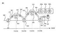
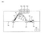
図1は、本実施形態に係る教示装置200をロボットアーム機構130とともに示す斜視図である。本実施形態に係る教示装置200は、ロボット装置100と通信可能に接続される。ロボット装置100はロボットアーム機構130を備える。ロボットアーム機構130は、略円筒形状の支柱部(基部)2と、支柱部2の上部に載置される起伏部4と、起伏部4から伸延するアーム部5と、アーム部5の先端に取り付けられる手首部6を備える。手首部6の第6関節部J6の回転部には図示しないアダプタが設けられている。このアダプタにエンドエフェクタ7(手先効果器)が取り付けられる。 FIG. 1 is a perspective view showing a
ロボットアーム機構130は、複数、ここでは6つの関節部J1,J2,J3,J4,J5,J6を有する。第1、第2、第3関節部J1,J2,J3は手首部6の位置を変化させる根元3軸と呼ばれる。第1、第2、第3関節部J1,J2,J3の主要構成部分は支柱部2に収容される。第4、第5、第6関節部J4,J5,J6は主にエンドエフェクタ7(手先効果器)の姿勢を変化させる手首3軸と呼ばれる。第4、第5、第6関節部J4,J5,J6の主要構成部分は手首部6に収容される。 The
第1関節部J1は、鉛直方向に平行な回転軸RA1を備える旋回用のねじり回転関節部であり、第1関節部J1の回転によりアーム部5は左右に旋回回転される。第2関節部J2は、回転軸RA1に対して直交する回転軸RA2を備える起伏用のねじり回転関節部であり、第2関節部J2の回転によりアーム部5は上下に起伏する。第3関節部J3は、直動伸縮機構により提供される。直動伸縮機構は発明者らが新規に開発した構造を備えており、可動範囲の観点でいわゆる従来の直動関節とは明確に区別される。第3関節部J3のアーム部5は伸縮軸RA3に沿って伸縮する。このように、根元3軸は、旋回用ねじり関節部、起伏用ねじり関節部及び直動伸縮機構で構成される。つまり、図1に示すロボットアーム機構130は極座標型である。 The first joint J1 is a twisting rotary joint having a rotation axis RA1 parallel to the vertical direction, and the
第4〜第6関節部J4〜J6はそれぞれ直交3軸の回転軸RA4〜RA6を備える。第4関節部J4は伸縮軸RA3と略一致する回転軸RA4を中心としたねじり回転関節部であり、この第4関節部J4の回転によりエンドエフェクタ7は揺動回転される。第5関節部J5は回転軸RA4に対して垂直に配置される回転軸RA5を中心とした曲げ回転関節部であり、この第5関節部J5の回転によりエンドエフェクタ7は前後に傾動回転される。第6関節部J6は回転軸RA4と回転軸RA5とに対して垂直に配置される回転軸RA6を中心としたねじり回転関節部であり、この第6関節部J6の回転によりエンドエフェクタ7は軸回転される。 The fourth to sixth joint portions J4 to J6 respectively have rotation axes RA4 to RA6 of three orthogonal axes. The fourth joint J4 is a twist rotary joint centering on a rotation axis RA4 substantially coinciding with the extension axis RA3, and the end effector 7 is pivoted and rotated by the rotation of the fourth joint J4. The fifth joint J5 is a bending rotary joint centered on a rotation axis RA5 disposed perpendicularly to the rotation axis RA4, and the end effector 7 is tilted forward and backward by the rotation of the fifth joint J5. . The sixth joint J6 is a torsional rotary joint centering on a rotation axis RA6 disposed perpendicular to the rotation axis RA4 and the rotation axis RA5, and rotation of the sixth joint J6 causes the end effector 7 to be an axis. It is rotated.
このように、エンドエフェクタ7は、第1、第2、第3関節部J1,J2,J3により任意位置に移動され、第4、第5、第6関節部J4,J5,J6により任意姿勢に配置される。特に第3関節部J3のアーム部5の伸縮距離の長さは、支柱部2の近接位置から遠隔位置までの広範囲にエンドエフェクタ7を到達させることを可能にする。第3関節部J3はそれを構成する直動伸縮機構により実現される直線的な伸縮動作とその伸縮距離の長さとが従前の直動関節と異なる特徴的な点である。 Thus, the end effector 7 is moved to an arbitrary position by the first, second and third joints J1, J2 and J3, and is put in an arbitrary posture by the fourth, fifth and sixth joints J4, J5 and J6. Be placed. In particular, the length of the telescopic distance of the
図2には、本実施形態に係る教示装置200を含むロボット装置100全体の構成を示している。ロボット装置100に教示装置200が通信可能に接続される。ロボット装置100から教示装置200に、手先基準点の位置情報、手先姿勢情報が送信される。教示装置200からロボット装置100に、手先基準点の移動情報、タスクプログラムのデータファイルが送信される。 FIG. 2 shows the entire configuration of the
(ロボット装置)
ロボット装置100が備えるロボットアーム機構130の各関節部は、関節部を駆動するアクチュエータ(モータ)132と、モータ132を制御するモータドライバ133と、モータ132の回転角度を計測するエンコーダとを有する。モータドライバ133により、動作制御部103からの指令値に応じたパルス電力がモータ132に供給され、これによりモータ132が回転する。エンコーダ131(ロータリエンコーダ131)は、モータ132の駆動軸又は関節部の回転軸に取り付けられる。エンコーダ131は、モータ132の回転角度を検出し、検出したモータ132の回転角度に関するデータを動作制御部103に送信する。(Robot equipment)
Each joint of the
ロボット装置100は、通信部104、記憶部108、動作制御部103、及びシステム制御部101を有する。通信部104は、教示装置200に対して各種データ等の通信を実行する。記憶部108は、タスクプログラムのデータファイルを記憶する。システム制御部101は、ロボット装置100の各要素を統括して制御する。動作制御部103は、記憶部108から読み出されたタスクプログラムを用いて各関節部の関節角度(指令値)を発生し、発生した指令値を各関節部のモータドライバ133に送信する。また、動作制御部103は、教示装置200から受信した手先基準点の移動情報に基づいて、各関節部の関節角度(指令値)を発生し、発生した指令値を各関節部のモータドライバ133に送信する。さらに、動作制御部103は、エンコーダ131で検出されたモータ132の回転角度に基づいて、各関節部の関節変数を計算し、計算した関節部変数に基づいて、アーム構造のリンクパラメータに応じて既定された同次変換行列に従って順運動学によりロボット座標系から見た手先基準点の位置と手先姿勢とを計算する。なお関節変数とは、関節部J1,J2,J4,J5、J6では基準位置からの正負の回転角度であり、関節部J3であれば最も収縮した状態からの伸張距離(直動変位)である。 The
手先姿勢とは、手先座標系Σhのロボット座標系Σbに対する直交3軸各々周りの回転角(Xh軸周りの回転角(ヨウ角)α、Yh軸周りの回転角(ピッチ角)β、Zh軸周りの回転角(ロール角)γとして与えられる。ロボット座標系Σbは第1関節部J1の第1回転軸RA1上の任意位置を原点とした座標系である。ロボット座標系Σbの直交3軸(Xb、Yb,Zb)において、Zb軸は第1回転軸RA1に平行な軸である。Xb軸とYb軸とは互いに直交し、且つZb軸に直交する軸である。ここでは、Xb軸は、第1関節部J1の可動範囲の中心を通る軸である。すなわち、Xb軸は基部2の前後方向に平行な軸であり、Yb軸は基部2の幅(左右)方向に平行な軸である。手先座標系Σhは手首部6に取り付けられた吸着パッドの吸着面の中心位置を原点(手先基準点)とした座標系である。手先座標系Σhの直交3軸(Xh、Yh,Zh)において、Zh軸は第6回転軸RA6に平行な軸である。Xh軸とYh軸とは互いに直交し、且つZh軸に直交する軸である。 Hand postures are the rotation angles (rotation angles around the Xh axis (Yaw angle) α, Yh rotation angles (pitch angle) β, Zh axes around the three orthogonal axes with respect to the robot coordinate system b b of the hand coordinate system h h The rotation angle (roll angle) γ of the surrounding is given as a robot coordinate system bb having an origin at an arbitrary position on the first rotation axis RA1 of the first joint J1.Two orthogonal axes of the robot coordinate system bb In (Xb, Yb, Zb), the Zb axis is an axis parallel to the first rotation axis RA 1. The Xb axis and the Yb axis are orthogonal to each other and orthogonal to the Zb axis. Is an axis passing through the center of the movable range of the first joint J 1, that is, the Xb axis is an axis parallel to the back and forth direction of the
(教示装置)
教示装置200は、システム制御部201と、操作部202と、表示部203と、通信部204と、教示画面発生部205と、工程図発生部206と、タスクプログラム発生部207と、記憶部208とを有する。(Teaching device)
The
通信部204は、教示装置200に対して各種データ等の通信を実行する。操作部202は、表示部203に表示されているアイコン等を指し示すためのポインティングデバイス、例えばマウス、キーボード等である。表示部203は、システム制御部201の制御に従って、教示画面発生部205により発生された教示画面300を表示する。記憶部208は、極座標型ロボット装置100のティーチング用のソフトウェアのデータを記憶する。このソフトウェアのデータの中には、過去に発生されたタスクプログラムのデータ、タスクプログラムに対応する工程図のデータ等が含まれる。 The
システム制御部201は、CPU、ROM、RAM等を備える。ROMは、OSのデータ等を記憶する。RAMは、プログラム実行中のデータを一時的に格納するワークエリア等として機能する。システム制御部201は、記憶部208又はROMに記憶されたプログラムを読み出し実行することにより、各種の制御を行う。具体的には、システム制御部201により記憶部208に記憶された極座標型ロボット装置100の教示プログラムが実行されることにより、後述の教示画面発生部205と工程図発生部206とタスクプログラム発生部207との機能が実現される。なお、ここでは、教示プログラムは、記憶部208に記憶されるとしたが、コンピュータが読み取り可能な記録媒体、例えば、CD−ROM、フレキシブルディスクを介して、又は通信回線を利用して記憶部208にダウンロードすることもできる。 The
タスクプログラム発生部207は、操作部202を介して入力された手先作業と、ロボット装置100から受信した手先基準点の位置情報、手先姿勢情報に従って、タスクプログラムのデータを発生する。 The task
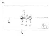
教示画面発生部205は、システム制御部201の制御に従って、図3に示す教示画面300のデータを発生する。教示画面発生部205により発生された教示画面300のデータは、システム制御部201の制御に従って、表示部203に表示される。図3は、本実施形態に係る教示装置200の教示画面300を示す平面図である。図3に示すように、教示画面300は、新規ボタン310と、開くボタン320と、設定ボタン330と、工程図表示領域340とを有する。工程図表示領域340には、工程図345が表示される。工程図345は、旋回、且つ起伏可能な伸縮性を有するアーム部5を備える極座標形ロボットの動作の概要を図形で視覚的に表す図であり、工程図発生部206により発生される。新規ボタン310がクリックされると、工程図表示領域340に初期的な工程図(図9)が表示される。開くボタン320がクリックされると、記憶部208に記憶されている複数のタスクプログラムのリストがフローティングウィンドウに表示され、複数のタスクプログラムからユーザにより選択されたタスクプログラムに対応する工程図が工程図表示領域340に表示される。設定ボタン330がクリックされると、工程図の各種設定を行うための設定画面が表示される。ユーザは、設定画面上で、例えば初期的な工程図の設定、手先作業の種類の追加等を行うことができる。 Under the control of the
工程図345では、極座標型ロボット装置100の手先作業をその種類に応じた態様で表す複数の図形要素351、352,353,354,355、356が横軸380(第1軸)に沿って配列されている。図形要素353,354,355,356は、ロボットの手先作業の種類に応じた態様で表す手先作業図形要素である。手先作業図形要素353,355は手先作業「つかむ」を表し、手先作業図形要素354,356は手先作業「はなす」を表す。複数の手先作業図形要素353,354,355,356は、ロボットの作業開始を表す図形要素351と、作業終了を表す図形要素352との間に作業順に従って配列される。手先作業図形要素353,354,355,356各々は、対応する手先作業を実行するときのロボットの手先基準点の高さに従って横軸380に直交する縦軸(第2軸)に沿って配置される。また、手先作業図形要素353,354,355,356各々は対応する手先作業を実行するときのアーム部5の旋回角度に従って回転される。隣り合う図形要素が連結線で連結される。連結線371,372,373,374,375は前後の手先作業におけるアーム部5の伸縮長の変化又は手先基準点の旋回半径の変化を色相、彩度、明度、又は線幅の少なくとも一つの変化として表す。連結線371,372,373,374,375の略中央には、手先作業追加用図形要素361,362,363,364,365がそれぞれ配置されている。 In the
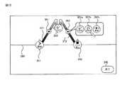
工程図345に含まれる、手先作業追加用図形要素、手先作業図形要素及び連結線の詳細について、図4乃至図8を参照して説明する。図4、図5、図6、図7は、図3の工程図345の手先作業追加用図形要素の機能、手先作業図形要素の向き、手先作業図形要素の位置、及び連結線をそれぞれ説明するための説明図である。図8は、図7の補足説明図である。 The details of the manual work addition graphic element, the manual work graphic element, and the connecting line included in the
(手先作業追加用図形要素)
工程図発生部206は、ユーザにより入力された手先作業図形要素を含めた複数の図形要素を作業順に従って横軸380に沿って再配列し、隣り合う手先作業図形要素を連結線で連結する。ユーザによる手先作業図形要素の追加は、手先作業追加用図形要素を介して行うことができる。例えば、手先作業追加用図形要素がクリックされると、手先作業の追加候補として複数の手先作業図形要素が表示される。ユーザは、一覧表示された複数の手先作業図形要素から追加する手先作業に対応する手先作業図形要素を選択する。これにより、ユーザにより選択された手先作業図形要素は、クリックした手先作業追加用図形要素に対応する作業順に追加される。図4に示す例では、手先作業3と手先作業4との間の手先作業追加用図形要素364がクリックされ、手先作業「つかむ」を表す手先作業図形要素364aと、手先作業「はなす」を表す手先作業図形要素364bと、手先の経由点を表す手先作業図形要素364cとが表示されている。この中からユーザにより選択された手先作業図形要素は、新たな手先作業4として追加される。(Graphic element for manual task addition)
The process
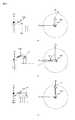
(手先作業図形要素の説明:向き)
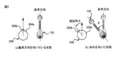
工程図発生部206は手先作業点の位置情報と手先の姿勢情報とに基づいてアーム部5の旋回角度を計算し、計算したアーム部5の旋回角度に従って手先作業図形要素350を回転する。手先作業図形要素350は、円形状の枠体350aの周縁に三角形状の突起350bが結合されてなる。円形状の枠体内350aには、手先作業の種類を示す図柄及びテキストが記載されている。手先作業図形要素350は、上方からみたときのロボットアーム機構130を模しており、円形状の枠体350aは支柱部2、突起350bはアーム部5を表す。すなわち、手先作業図形要素350の突起350bの向きは、対応する手先作業を実行するときのアーム部5の向きを表す。手先作業図形要素350の突起350bの向きは、実際のアーム部5の向きに対応付けされており、例えば、図5(a)に示すように、突起350bが上を向いている手先作業図形要素350を、対応する手先作業を実行するときにアーム部5が基準方向を向いていることを表し、このときの旋回角を0°とする。アーム部5の基準方向は、ロボット座標系のXb軸の正方向、つまりアーム部5の旋回範囲の中心を通る、支柱部2の前方方向である。図5(b)に示すように、突起350bが上方向から左に角度θ傾いた方向を向いている手先作業図形要素350は、対応する手先作業を実行するときにアーム部5が基準方向から左に角度θ傾いた方向を向いていることを表す。(Description of hand work graphic element: direction)
The process
(手先作業図形要素の説明:縦軸上の位置)
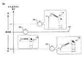
工程図発生部206は手先作業点の位置情報と手先の姿勢情報とに基づいて手先基準点の高さを計算し、計算した手先基準点の高さに従って縦軸に沿って手先作業図形要素350を配置する。工程図345の縦軸は手先基準点の高さを表している。縦軸の最下位置は、実際の手先基準点の最下位置に対応付けられ、縦軸の最上位置は、実際の手先基準点の最上位置に対応付けられている。例えば、縦軸上における横軸380の位置は手先基準点の基準位置に対応付けられている。基準位置とは、アーム部5が水平姿勢であるときの、ロボットアーム機構130の設置面に対する手先基準点の高さである。したがって、図6に示すように、横軸380上に配置された手先作業図形要素350は、対応する手先作業を実行するときにアーム部5が水平姿勢であることを表している。横軸380よりも上方の位置に配置された手先作業図形要素350は、対応する手先作業を実行するときに手先基準点が基準高よりも上に配置されている、つまりアーム部5が水平姿勢から上方に起きた姿勢であることを表している。手先作業図形要素350の縦軸上の位置hv1は、対応する手先作業を実行するときの手先基準点の高さhr1に対応している。横軸380よりも下方の位置に配置された手先作業図形要素350は、対応する手先作業を実行するときに手先基準点が基準高よりも下に配置されている、つまりアーム部5が水平姿勢から下方に伏せた姿勢であることを表している。手先作業図形要素350の縦軸上の位置hv2は、対応する手先作業を実行するときの手先基準点の高さhr2に対応している。(Description of hand work graphic element: position on the vertical axis)
The process
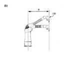
(連結線の説明)
工程図発生部206は手先作業点の位置情報と手先の姿勢情報とに基づいてアーム部5の伸縮長又は手先基準点の旋回半径を計算し、計算したアーム部5の伸縮長又は手先基準点の旋回半径に従って、連結線の色相、彩度、明度、又は線幅の少なくとも一つのを変化させる。連結線370の色はアーム部5の伸縮長又は手先基準点の旋回半径を表している。換言すると、連結線370の色は手先基準点がロボットアーム機構130の設置位置からどれだけ離れているかを表している。ここでは、手先基準点の旋回半径の変化が連結線370の色の濃淡の変化により表されている。色の濃淡は、明度と彩度の組合せにより表される。手先基準点の旋回半径Rは、図8に示すように、アーム部5の伸縮長とアーム部5の起伏角とにより決まる。手先基準点の最大旋回半径Rmaxが濃色に対応付けされ、手先基準点の最小旋回半径Rminが薄色に対応付けされている。したがって、連結線には、手先基準点の旋回半径に従って、最大旋回半径Rmax時の濃色と最小旋回半径Rmin時の薄色との間の色が割り当てられる。例えば、前後の手先作業図形要素を連結する連結線の色が変化していないとき、手先基準点はその旋回半径を維持した状態で、前の作業点から次の作業点まで移動されることを表す。前後の手先作業図形要素を連結する連結線の色が、前方の手先作業図形要素から後方の手先作業図形要素に向かって徐々に薄く変化しているとき、手先基準点はその旋回半径を徐々に長くしながら、前の作業点から次の作業点まで移動されることを表す。なお、連結線の線幅の変化により、手先基準点の旋回半径を表す場合、前後の手先作業図形要素を連結する連結線の線幅が、前方の手先作業図形要素から後方の手先作業図形要素に向かって徐々に狭く変化しているとき、手先基準点はその旋回半径を徐々に長くしながら、前の作業点から次の作業点まで移動されることを表す。(Description of connecting line)
The process
(教示手順)
本実施形態に係る教示装置200を用いたロボットの教示作業の手順について図9乃至図15を参照して説明する。図9乃至図13は本実施形態に係る教示装置200を用いたロボットの教示作業の手順1乃至手順5をそれぞれ示す図である。ここでは、作業開始点P0から作業点P1に移動し、ワークをつかみ、作業点P2に移動し、ワークをリリースし、作業終了点として作業開始点P0に戻るまでのタスクに関するタスクプログラムをロボットに教示する手順について説明する。図14は、図9乃至図13の補足説明図である。図14(a),図14(b)、図14(c)は作業開始点(作業終了点)P0,作業点P1,作業点P2をそれぞれ示す。図15は、図14に示す工程図の編集方法を説明するための説明図である。(Teaching procedure)
The procedure of the teaching operation of the robot using the
教示画面300の新規ボタン310がクリックされると、工程図表示領域340に図9に示す初期的な工程図(図9)が表示される。ユーザは、操作部202を使用して、又は直接手でアーム部5を動かして、手先基準点を作業点P1に移動させる。その後、図10に示すように、ユーザは手先作業追加用図形要素361を選択し、表示された複数の手先作業図形要素361a,361b,361cから、作業点P1で行う手先作業「つかむ」を表す手先作業図形要素361aを選択する。これにより、手先作業「つかむ」の作業点P1が登録され、図11に示すように、図形要素351、352の間に、手先作業「つかむ」を表す手先作業図形要素353が追加される。追加された手先作業図形要素353は作業点P1の高さに従って、縦軸上に沿って配置され、追加された手先作業図形要素353はアーム部5の旋回角度に従って回転される。また、図形要素351と手先作業図形要素353とを連結する連結線371は、作業開始点P0の位置と作業点P1の位置とに基づいて計算された手先基準点の旋回半径に従って、その色が変化される。同様に、手先作業図形要素353と図形要素352とを連結する連結線372は、作業点P1の位置と作業終了点P0の位置とに基づいて計算された手先基準点の旋回半径に従って、その色が変化される。 When a
図14に示すように、作業点P1は作業開始点P0よりも高い位置であるため、手先作業図形要素353は、図形要素351よりも縦軸に沿って上方の位置に配置される。作業点P1は基準方向から左に90度旋回した方向に配置されているため、手先作業図形要素353は左に90度回転される。アーム部5の旋回軸(Zb軸)に対して作業点P1は作業開始点P0よりも遠い位置に配置されているため、連結線371の色が図形要素351から手先作業図形要素353に向けて徐々に薄く変化される。同様に、アーム部5の旋回軸(Zb軸)に対して作業終了点P0は作業点P1よりも近い位置に配置されているため、連結線372の色が手先作業図形要素353から図形要素352に向けて徐々に濃く変化される。なお、連結線の形状により、手先基準点の高さ方向の軌道の概要を表すことができる。例えば、連結線371は、手先基準点が作業開始点P0から作業点P1に向かって徐々に上に上がっていき、一旦作業点P1の上方の位置に配置され、その後、作業点P1に下降する高さ方向の軌道を表している。 As shown in FIG. 14, since the work point P1 is at a position higher than the work start point P0, the hand work
次に、ユーザは、操作部202を使用して、又は直接手でアーム部5を動かして、手先基準点を作業点P2に移動させる。その後、図12に示すように、ユーザは、手先作業図形要素353と図形要素352との間に配置されている手先作業追加用図形要素362を選択し、表示された複数の手先作業図形要素362a,362b,362cから、作業点P2で行う手先作業「はなす」を表す手先作業図形要素362bを選択する。手先作業「はなす」の作業点P2が登録され、図13に示すように、手先作業図形要素353と図形要素352との間に、手先作業「はなす」を表す手先作業図形要素354が追加される。追加された手先作業図形要素354は作業点P2の高さに従って、縦軸上に沿って配置される。また、追加された手先作業図形要素354はアーム部5の旋回角度に従って回転される。さらに、手先作業図形要素353と手先作業図形要素354とを連結する連結線372は、作業点P1の位置と作業点P2の位置とに基づいて計算された手先基準点の旋回半径に従って、その色が変化される。同様に、手先作業図形要素354と図形要素352とを連結する連結線373は、作業点P2の位置と作業終了点P0の位置とに基づいて計算された手先基準点の旋回半径に従って、その色が変化される。 Next, the user moves the
図15に示すように、作業点P2は作業点P1よりも低い位置であり、作業開始点P0と同位置であるため、手先作業図形要素354は、横軸380上に配置される。作業点P2は基準方向に配置されているため、手先作業図形要素354は回転されない。つまり、手先作業図形要素354は、突起が上を向いた状態で配置される。アーム部5の旋回軸(Zb軸)に対して作業点P2は作業点P1と同位置に配置されているため、連結線372の色が手先作業図形要素353から手先作業図形要素354に向けて同一である。同様に、アーム部5の旋回軸(Zb軸)に対して作業終了点P0は作業点P2よりも近い位置に配置されているため、連結線373の色が手先作業図形要素354から図形要素352に向けて徐々に濃く変化される。連結線373は、手先基準点が作業点P2から作業終了点P0に向かって水平に移動する軌道を表している。 As shown in FIG. 15, the work point P2 is at a position lower than the work point P1 and the same position as the work start point P0, so the hand work
ユーザは、すべての手先作業の作業点の登録作業が完了した後、完了ボタン390をクリックすることで教示作業を完了させる。完了ボタン390がクリックされたのを契機に、タスクプログラム発生部207は、手先作業に対して手先基準点の位置と手先姿勢とを関連付け、それらを作業順に記述したタスクプログラムのデータを発生する。このタスクプログラムのデータは、工程図345のデータと関連付けて記憶部208に記憶される。 The user completes the teaching work by clicking the
なお、教示中の工程図及び完成された記憶部208から読み出した工程図において、手先作業の変更、作業点の変更等の編集することもできる。図15に示すように、手先作業図形要素353をクリックすることで、複数の手先作業図形要素353a,353b,353cが表示される。作業点P1の位置を変更したいとき、手先基準点を変更後の位置に移動させた後、手先作業「つかむ」を表す手先作業図形要素353aを選択すればよい。また、手先作業を「つかむ」から「はなす」に変更したいとき、手先基準点を変更後の位置に移動させた後、手先作業「はなす」を表す手先作業図形要素353bを選択すればよい。 In addition, in the process drawing during teaching and the process drawing read out from the completed
以上説明した本実施形態に係る教示装置200によれば、ロボットの動作の教示を工程図上のユーザ操作により行うことができる。工程図はロボットの動作の概要を表す図である。工程図を用いて教示作業を行うことで、手先作業に対して作業点を登録するたびに、登録した手先作業を表す手先作業図形要素が工程図に表示され、登録した作業点の位置に従って、手先作業図形要素位置、向き及び連結線の色が変化される。そのため、ユーザは工程図を見て手先作業の作業点の登録作業がきちんと行えているかを確認しながら、ロボットの動作の教示を行うことができる。また、工程図に表示されている手先作業図形要素の種類により、どのような種類の手先作業を登録したのかをユーザは視覚的に理解することができる。また、工程図に表示されている手先作業図形要素350の位置、向き及び連結線370の色により、作業点の位置や作業点の間の手先軌道の概要をユーザは視覚的に理解することができる。 According to the
手先作業図形要素350の位置、手先作業図形要素350の向き及び連結線370の色だけで、タスクプログラムで記述されているロボットアーム機構130の動作の概要をユーザに理解させることができるのは、発明者らが開発したロボットアーム機構130が直動伸縮関節J3を備える極座標型であり、ユーザが直感的に理解できる単純なロボット動作を実現したためである。図1に記載のロボットアーム機構130は、手先基準点(エンドエフェクタ)を、根元3軸(旋回関節部J1、起伏関節部J2、直動伸縮関節部J3)により移動させることができ、その可動領域は、旋回関節部J1の実装上の動作可能な旋回角度と起伏関節部J2の実装上の動作可能な起伏角度と直動伸縮関節部J3のアーム部5の最大伸張距離とで規定される立体的な領域である。すなわち、手先から基部2までの直線的な範疇でアーム部5が動作することから、ユーザはアーム部5の旋回角度、アーム部5の旋回半径及び手先基準点の高さから、作業点の位置及び手先軌道を容易に予測することができる。 The position of the hand work
ロボットアーム機構130の手先基準点の位置を規定する複数のパラメータのうち、アーム部5の旋回角度、アーム部5の旋回半径、及び手先基準点の高さの3つのパラメータを選択し、その選択した3つのパラメータを視覚的に工程図上で表現したことが、本実施形態に係る教示装置200の一つの特徴である。 Of a plurality of parameters defining the position of the hand reference point of the
なお実施形態は教示装置に限定されない。本実施形態に係る教示装置200の教示機能を省略し、タスクプログラムに対応する工程図を表示する機能を有する表示装置として使用することもできる。表示装置に表示された工程図を見ることで、ユーザは、対応するタスクプログラムで記述されている手先作業、手先軌道及び手順の概要を容易に確認することができる。 The embodiment is not limited to the teaching device. The teaching function of the
本発明のいくつかの実施形態を説明したが、これらの実施形態は、例として提示したものであり、発明の範囲を限定することは意図していない。これら実施形態は、その他の様々な形態で実施されることが可能であり、発明の要旨を逸脱しない範囲で、種々の省略、置き換え、変更を行うことができる。これら実施形態やその変形は、発明の範囲や要旨に含まれると同様に、特許請求の範囲に記載された発明とその均等の範囲に含まれるものである。 While certain embodiments of the present invention have been described, these embodiments have been presented by way of example only, and are not intended to limit the scope of the invention. These embodiments can be implemented in other various forms, and various omissions, replacements, and modifications can be made without departing from the scope of the invention. These embodiments and modifications thereof are included in the invention described in the claims and the equivalents thereof as well as included in the scope and the gist of the invention.
300…教示画面、310…新規ボタン、320…開くボタン、330…設定ボタン、340…工程図表示領域、345…工程図、351,352…図形要素、353,354,355,356…手先作業図形要素、361,362,363,364,365…手先作業追加用図形要素、371,372,373,374,375…連結線、390…完了ボタン。 300 ... teaching screen, 310 ... new button, 320 ... open button, 330 ... setting button, 340 ... process chart display area, 345 ... process chart, 351, 352 ... graphic element, 353, 354, 355, 356 ... hand work graphic Elements, 361, 362, 363, 364, 364, 365 ... Graphic elements for additional work at hand, 371, 372, 373, 374, 375 ... Connection lines, 390 ... Complete button.
Claims (11)
Translated fromJapanese前記工程図は、前記極座標型ロボットの手先作業の種類に応じた態様で表現される複数の手先作業図形要素が第1軸に沿ってその作業順に従って配列され、前記手先作業図形要素各々が手先基準点の高さに従って前記第1軸に直交する第2軸に沿って配置され、前記手先作業図形要素各々が前記アームの旋回角度に従って回転され、前記手先作業図形要素の間が前記アームの伸縮長又は前記手先基準点の旋回半径の変化を色相、彩度、明度及び線幅の少なくとも一つの変化として表現する連結線で連結されてなることを特徴とする教示装置。In a teaching device for teaching a motion to a polar coordinate type robot that supports an arm having elasticity in a pivotable and inclinable manner, and creating and displaying a flow chart representing the outline of the motion,
In the process diagram, a plurality of hand work graphic elements represented in a mode according to the type of the polar coordinate robot hand work are arranged along the first axis according to the work order, and each of the hand work graphic elements is hand handed Arranged along a second axis orthogonal to the first axis according to the height of the reference point, each of the hand work graphic elements is rotated according to the pivot angle of the arm, and between the hand work graphic elements is an expansion and contraction of the arm A teaching apparatus comprising: a connecting line representing a change of a turning radius of a length or the hand reference point as a change of at least one of hue, saturation, lightness, and line width.
前記工程図は、前記多関節型ロボットの手先作業の種類に応じた態様で表現される複数の手先作業図形要素が第1軸に沿ってその作業順に従って配列され、前記手先作業図形要素各々が手先基準点の高さに従って前記第1軸に直交する第2軸に沿って配置されてなることを特徴とする教示装置。In a teaching apparatus for teaching an operation to an articulated robot and creating and displaying a process chart showing an outline of the operation,
In the process diagram, a plurality of hand work graphic elements expressed in a mode according to the type of hand work of the articulated robot are arranged along the first axis according to the work order, and each of the hand work graphic elements is The teaching apparatus is arranged along a second axis orthogonal to the first axis according to the height of the hand reference point.
前記記憶部から読み出されたタスクプログラムに基づいて前記極座標型ロボットの動作の概要を表す工程図のデータを発生する工程図発生部と、
前記工程図を表示する表示部とを具備し、
前記工程図は、前記極座標型ロボットの手先作業の種類に応じた態様で表現される複数の手先作業図形要素が第1軸に沿ってその作業順に従って配列され、前記手先作業図形要素各々が手先基準点の高さに従って前記第1軸に直交する第2軸に沿って配置され、前記手先作業図形要素各々が前記アームの旋回角度に従って回転され、前記手先作業図形要素の間が前記アームの伸縮長又は前記手先基準点の旋回半径の変化を色相、彩度、明度及び線幅の少なくとも一つの変化として表現する連結線で連結されてなることを特徴とする表示装置。A storage unit for storing data of a task program for instructing a polar coordinate type robot having a flexible and pivotable arm that supports an elastic arm so as to be pivotable and inclinable;
A process chart generating unit that generates data of a process chart showing an outline of the operation of the polar coordinate type robot based on the task program read from the storage unit;
And a display unit for displaying the process chart,
In the process diagram, a plurality of hand work graphic elements represented in a mode according to the type of the polar coordinate robot hand work are arranged along the first axis according to the work order, and each of the hand work graphic elements is hand handed Arranged along a second axis orthogonal to the first axis according to the height of the reference point, each of the hand work graphic elements is rotated according to the pivot angle of the arm, and between the hand work graphic elements is an expansion and contraction of the arm A display device characterized in that it is connected by a connecting line which expresses a change of a turning radius of a length or the hand reference point as at least one change of hue, saturation, lightness and line width.
前記記憶部から読み出されたタスクプログラムに基づいて前記多関節型ロボットの動作の概要を表す工程図のデータを発生する工程図発生部と、
前記工程図を表示する表示部とを具備し、
前記工程図は、前記多関節型ロボットの手先作業の種類に応じた態様で表現される複数の手先作業図形要素が第1軸に沿ってその作業順に従って配列され、前記手先作業図形要素各々が手先基準点の高さに従って前記第1軸に直交する第2軸に沿って配置されてなることを特徴とする表示装置。A storage unit for storing data of a task program for instructing an articulated robot to operate;
A process chart generating unit that generates data of a process chart showing an outline of the operation of the articulated robot based on the task program read from the storage unit;
And a display unit for displaying the process chart,
In the process diagram, a plurality of hand work graphic elements expressed in a mode according to the type of hand work of the articulated robot are arranged along the first axis according to the work order, and each of the hand work graphic elements is A display device characterized in that the display device is disposed along a second axis orthogonal to the first axis according to the height of the hand reference point.
前記極座標型ロボットに対して前記アームの伸縮動作、旋回動作及び起伏動作の実行命令をユーザ指示に従って出力する手段と、
前記極座標型ロボットの手先作業をその種類とともに入力する手段と、
前記教示された動作の概要を表す工程図を作成する手段と、
前記作成された工程図を表示する手段とをコンピュータに実現させるものであり、
前記工程図を作成する手段は、前記極座標型ロボットの手先作業の種類に応じた態様で表現される複数の手先作業図形要素を第1軸に沿ってその作業順に従って配列し、前記手先作業図形要素各々を手先基準点の高さに従って前記第1軸に直交する第2軸に沿って配置し、前記手先作業図形要素各々を前記アームの旋回角度に従って回転し、前記手先作業図形要素の間を前記アームの伸縮長又は前記手先基準点の旋回半径の変化を色相、彩度、明度及び線幅の少なくとも一つの変化として表現する連結線で連結することを特徴とする教示プログラム。In a teaching program for teaching an operation of a polar coordinate type robot which supports an elastic arm rotatably and inclinably.
Means for outputting an execution command of the extension / contraction operation, the turning operation and the raising / lowering operation of the arm to the polar coordinate type robot according to a user instruction;
A means for inputting the hand work of the polar coordinate robot together with its type;
A means for creating a process chart outlining the taught operation;
Means for causing a computer to realize means for displaying the created process chart;
The means for creating the process diagram arranges a plurality of hand work graphic elements represented in a mode according to the type of hand work of the polar coordinate type robot along a first axis according to the work order, and the hand work graphic figure Each element is disposed along a second axis orthogonal to the first axis according to the height of the hand reference point, and each of the hand work graphic elements is rotated according to the pivot angle of the arm, and between the hand work graphic elements A teaching program comprising: connecting a change line of an extension length of the arm or a turning radius of the hand reference point as a change in at least one of hue, saturation, lightness and line width.
前記多関節型ロボットに対して関節動作の実行命令をユーザ指示に従って出力する手段と、
前記多関節型ロボットの手先作業をその種類とともに入力する手段と、
前記教示された動作の概要を表す工程図を作成する手段と、
前記作成された工程図を表示する手段とをコンピュータに実現させるものであり、
前記工程図を作成する手段は、前記多関節型ロボットの手先作業の種類に応じた態様で表現される複数の手先作業図形要素を第1軸に沿ってその作業順に従って配列し、前記手先作業図形要素各々を手先基準点の高さに従って前記第1軸に直交する第2軸に沿って配置することを特徴とする教示プログラム。In a teaching program for teaching an operation to an articulated robot,
Means for outputting an execution instruction of joint motion to the articulated robot in accordance with a user instruction;
A means for inputting the hand work of the articulated robot together with its type;
A means for creating a process chart outlining the taught operation;
Means for causing a computer to realize means for displaying the created process chart;
The means for creating the process diagram arranges a plurality of hand work graphic elements represented in a mode according to the type of hand work of the articulated robot along a first axis according to the work order, and the hand work A teaching program, comprising: arranging each graphic element along a second axis orthogonal to the first axis according to the height of a hand reference point.
前記読み出されたタスクプログラムに基づいて前記極座標型ロボットの動作の概要を表す工程図を作成する手段と、
前記作成された工程図を表示する手段とをコンピュータに実現させるものであり、
前記工程図を作成する手段は、前記極座標型ロボットの手先作業の種類に応じた態様で表現される複数の手先作業図形要素を第1軸に沿ってその作業順に従って配列し、前記手先作業図形要素各々を手先基準点の高さに従って前記第1軸に直交する第2軸に沿って配置し、前記手先作業図形要素各々を前記アームの旋回角度に従って回転し、前記手先作業図形要素の間を前記アームの伸縮長又は前記手先基準点の旋回半径の変化を色相、彩度、明度及び線幅の少なくとも一つの変化として表現する連結線で連結することを特徴とする表示プログラム。A means for reading out data of a task program for instructing the polar coordinate type robot, which rotatably and inclinably supports the stretchable arm, to operate, from the storage unit;
A means for creating a process diagram showing an outline of the operation of the polar coordinate type robot based on the read task program;
Means for causing a computer to realize means for displaying the created process chart;
The means for creating the process diagram arranges a plurality of hand work graphic elements represented in a mode according to the type of hand work of the polar coordinate type robot along a first axis according to the work order, and the hand work graphic figure Each element is disposed along a second axis orthogonal to the first axis according to the height of the hand reference point, and each of the hand work graphic elements is rotated according to the pivot angle of the arm, and between the hand work graphic elements A display program comprising connecting a change line of the extension length of the arm or a turning radius of the hand reference point by a connecting line expressing the change of at least one of hue, saturation, lightness and line width.
前記読み出されたタスクプログラムに基づいて前記多関節型ロボットの動作の概要を表す工程図を作成する手段と、
前記作成された工程図を表示する手段とをコンピュータに実現させるものであり、
前記工程図を作成する手段は、前記多関節型ロボットの手先作業の種類に応じた態様で表現される複数の手先作業図形要素を第1軸に沿ってその作業順に従って配列し、前記手先作業図形要素各々を手先基準点の高さに従って前記第1軸に直交する第2軸に沿って配置することを特徴とする表示プログラム。Means for reading out data of a task program for instructing the operation of the articulated robot from the storage unit;
A means for creating a process diagram showing an outline of the operation of the articulated robot based on the read task program;
Means for causing a computer to realize means for displaying the created process chart;
The means for creating the process diagram arranges a plurality of hand work graphic elements represented in a mode according to the type of hand work of the articulated robot along a first axis according to the work order, and the hand work A display program characterized by arranging each of the graphic elements along a second axis orthogonal to the first axis in accordance with the height of the hand reference point.
Priority Applications (4)
| Application Number | Priority Date | Filing Date | Title |
|---|---|---|---|
| JP2017077167AJP6708581B2 (en) | 2017-04-07 | 2017-04-07 | Teaching device, display device, teaching program and display program |
| US15/940,466US20180290299A1 (en) | 2017-04-07 | 2018-03-29 | Teaching device, display device, teaching program, and display program |
| CN201810300696.8ACN109434842A (en) | 2017-04-07 | 2018-04-04 | The device of teaching and display, method and storage medium |
| DE102018205209.3ADE102018205209A1 (en) | 2017-04-07 | 2018-04-06 | Teaching device, display device, teaching program, and display program |
Applications Claiming Priority (1)
| Application Number | Priority Date | Filing Date | Title |
|---|---|---|---|
| JP2017077167AJP6708581B2 (en) | 2017-04-07 | 2017-04-07 | Teaching device, display device, teaching program and display program |
Publications (2)
| Publication Number | Publication Date |
|---|---|
| JP2018176326Atrue JP2018176326A (en) | 2018-11-15 |
| JP6708581B2 JP6708581B2 (en) | 2020-06-10 |
Family
ID=63587746
Family Applications (1)
| Application Number | Title | Priority Date | Filing Date |
|---|---|---|---|
| JP2017077167AActiveJP6708581B2 (en) | 2017-04-07 | 2017-04-07 | Teaching device, display device, teaching program and display program |
Country Status (4)
| Country | Link |
|---|---|
| US (1) | US20180290299A1 (en) |
| JP (1) | JP6708581B2 (en) |
| CN (1) | CN109434842A (en) |
| DE (1) | DE102018205209A1 (en) |
Cited By (2)
| Publication number | Priority date | Publication date | Assignee | Title |
|---|---|---|---|---|
| WO2021261326A1 (en)* | 2020-06-26 | 2021-12-30 | 川崎重工業株式会社 | Teaching device for robot and teaching program for robot |
| WO2023203697A1 (en)* | 2022-04-20 | 2023-10-26 | ファナック株式会社 | Simulation device |
Families Citing this family (6)
| Publication number | Priority date | Publication date | Assignee | Title |
|---|---|---|---|---|
| CN106217345B (en)* | 2016-08-31 | 2018-04-24 | 北京术锐技术有限公司 | The flexible Continuum Structure of gesture feedback can be achieved |
| US11292133B2 (en)* | 2018-09-28 | 2022-04-05 | Intel Corporation | Methods and apparatus to train interdependent autonomous machines |
| US12337480B2 (en)* | 2020-07-14 | 2025-06-24 | Fanuc Corporation | Robot control system |
| JP7456357B2 (en)* | 2020-11-16 | 2024-03-27 | 株式会社島津製作所 | Vial supply system and gas chromatography analysis system |
| JP7661714B2 (en)* | 2021-02-10 | 2025-04-15 | セイコーエプソン株式会社 | Teaching device, teaching method, and teaching program |
| US20240198520A1 (en)* | 2021-04-30 | 2024-06-20 | Fanuc Corporation | Robot teaching system, program, and program editing device |
Citations (13)
| Publication number | Priority date | Publication date | Assignee | Title |
|---|---|---|---|---|
| JPS6041966A (en)* | 1983-08-19 | 1985-03-05 | 協和醗酵工業株式会社 | Ampule weld-sealing dreg falling-off tool |
| JPH08215211A (en)* | 1995-02-16 | 1996-08-27 | Hitachi Ltd | Remote surgery support device and method |
| JPH08249026A (en)* | 1995-03-10 | 1996-09-27 | Fanuc Ltd | Programming method for system including robot |
| JP2002103258A (en)* | 2000-09-28 | 2002-04-09 | Sony Corp | Authoring system, authoring method and recording medium |
| JP2003266347A (en)* | 2002-03-18 | 2003-09-24 | Sony Corp | Motion editing device for leg type moving robot and motion editing method |
| WO2010092981A1 (en)* | 2009-02-12 | 2010-08-19 | 三菱電機株式会社 | Industrial robot system |
| JP2010531743A (en)* | 2007-07-04 | 2010-09-30 | アルデバラン ロボティクス エス、ア | Method for editing robot motion |
| JP2011108156A (en)* | 2009-11-20 | 2011-06-02 | Japan Science & Technology Agency | Device and method for instruction of cooking process |
| JP2014117781A (en)* | 2012-12-18 | 2014-06-30 | Yaskawa Electric Corp | Teaching data creation device, robot system, and teaching data creation method |
| JP2014213413A (en)* | 2013-04-25 | 2014-11-17 | 東芝テック株式会社 | Robot motion compilation device and compilation program |
| US20160052132A1 (en)* | 2014-08-20 | 2016-02-25 | Korea Institute Of Science And Technology | Robot motion data processing system using motion data reduction/restoration compatible to hardware limits |
| JP2016093869A (en)* | 2014-11-14 | 2016-05-26 | 株式会社クリエイティブマシン | Teaching data creation method, creation device, creation program, teaching data structure, and recording medium |
| JP2017007034A (en)* | 2015-06-22 | 2017-01-12 | ライフロボティクス株式会社 | Robot device |
Family Cites Families (14)
| Publication number | Priority date | Publication date | Assignee | Title |
|---|---|---|---|---|
| JPH0772844B2 (en)* | 1985-10-23 | 1995-08-02 | 株式会社日立製作所 | Robot teaching device |
| JPS6441966A (en)* | 1987-08-07 | 1989-02-14 | Hitachi Ltd | Method for displaying routing |
| JPH07129418A (en)* | 1993-11-08 | 1995-05-19 | Fanuc Ltd | Program control system for multi-task environment |
| JPH08194518A (en)* | 1995-01-19 | 1996-07-30 | Komatsu Ltd | Work robot teaching device and work program creating device |
| US5844795A (en)* | 1995-11-01 | 1998-12-01 | Allen Bradley Company, Llc | Diagnostic aid for industrial controller using multi-tasking architecture |
| US6268853B1 (en)* | 1999-09-30 | 2001-07-31 | Rockwell Technologies, L.L.C. | Data structure for use in enterprise controls |
| FR2799558B1 (en)* | 1999-10-08 | 2002-02-08 | Thomson Marconi Sonar Sas | METHOD FOR AUTOMATICALLY PLACING THE TASKS OF AN APPLICATION IN A SIGNAL PROCESSING MACHINE |
| US20040017400A1 (en)* | 2002-07-26 | 2004-01-29 | Ly Eric Thichvi | Method for project planning |
| SE526119C2 (en)* | 2003-11-24 | 2005-07-05 | Abb Research Ltd | Method and system for programming an industrial robot |
| JP4056542B2 (en)* | 2005-09-28 | 2008-03-05 | ファナック株式会社 | Offline teaching device for robots |
| DE102010052253B4 (en)* | 2010-11-23 | 2019-03-21 | Kuka Deutschland Gmbh | Method and control means for controlling a robot arrangement |
| US20150046856A1 (en)* | 2013-08-06 | 2015-02-12 | SmartSheet.com, Inc. | Interactive Charts For Collaborative Project Management |
| SG11201703891RA (en)* | 2014-12-26 | 2017-06-29 | Kawasaki Heavy Ind Ltd | Robot motion program generating method and robot motion program generating apparatus |
| US20170259433A1 (en)* | 2016-03-11 | 2017-09-14 | Seiko Epson Corporation | Robot control device, information processing device, and robot system |
- 2017
- 2017-04-07JPJP2017077167Apatent/JP6708581B2/enactiveActive
- 2018
- 2018-03-29USUS15/940,466patent/US20180290299A1/ennot_activeAbandoned
- 2018-04-04CNCN201810300696.8Apatent/CN109434842A/enactivePending
- 2018-04-06DEDE102018205209.3Apatent/DE102018205209A1/ennot_activeCeased
Patent Citations (13)
| Publication number | Priority date | Publication date | Assignee | Title |
|---|---|---|---|---|
| JPS6041966A (en)* | 1983-08-19 | 1985-03-05 | 協和醗酵工業株式会社 | Ampule weld-sealing dreg falling-off tool |
| JPH08215211A (en)* | 1995-02-16 | 1996-08-27 | Hitachi Ltd | Remote surgery support device and method |
| JPH08249026A (en)* | 1995-03-10 | 1996-09-27 | Fanuc Ltd | Programming method for system including robot |
| JP2002103258A (en)* | 2000-09-28 | 2002-04-09 | Sony Corp | Authoring system, authoring method and recording medium |
| JP2003266347A (en)* | 2002-03-18 | 2003-09-24 | Sony Corp | Motion editing device for leg type moving robot and motion editing method |
| JP2010531743A (en)* | 2007-07-04 | 2010-09-30 | アルデバラン ロボティクス エス、ア | Method for editing robot motion |
| WO2010092981A1 (en)* | 2009-02-12 | 2010-08-19 | 三菱電機株式会社 | Industrial robot system |
| JP2011108156A (en)* | 2009-11-20 | 2011-06-02 | Japan Science & Technology Agency | Device and method for instruction of cooking process |
| JP2014117781A (en)* | 2012-12-18 | 2014-06-30 | Yaskawa Electric Corp | Teaching data creation device, robot system, and teaching data creation method |
| JP2014213413A (en)* | 2013-04-25 | 2014-11-17 | 東芝テック株式会社 | Robot motion compilation device and compilation program |
| US20160052132A1 (en)* | 2014-08-20 | 2016-02-25 | Korea Institute Of Science And Technology | Robot motion data processing system using motion data reduction/restoration compatible to hardware limits |
| JP2016093869A (en)* | 2014-11-14 | 2016-05-26 | 株式会社クリエイティブマシン | Teaching data creation method, creation device, creation program, teaching data structure, and recording medium |
| JP2017007034A (en)* | 2015-06-22 | 2017-01-12 | ライフロボティクス株式会社 | Robot device |
Cited By (7)
| Publication number | Priority date | Publication date | Assignee | Title |
|---|---|---|---|---|
| WO2021261326A1 (en)* | 2020-06-26 | 2021-12-30 | 川崎重工業株式会社 | Teaching device for robot and teaching program for robot |
| JP2022007292A (en)* | 2020-06-26 | 2022-01-13 | 川崎重工業株式会社 | Robot teaching device and robot teaching program |
| KR20230028423A (en)* | 2020-06-26 | 2023-02-28 | 카와사키 주코교 카부시키 카이샤 | Robot teaching device and robot teaching program |
| US12208516B2 (en) | 2020-06-26 | 2025-01-28 | Kawasaki Jukogyo Kabushiki Kaisha | Teaching device for robot and teaching program for robot |
| JP7691813B2 (en) | 2020-06-26 | 2025-06-12 | 川崎重工業株式会社 | ROBOT TEACHING DEVICE, ROBOT TEACHING PROGRAM, AND ROBOT TEACHING METHOD |
| KR102832937B1 (en)* | 2020-06-26 | 2025-07-10 | 카와사키 주코교 카부시키 카이샤 | Robot teaching device and robot teaching program |
| WO2023203697A1 (en)* | 2022-04-20 | 2023-10-26 | ファナック株式会社 | Simulation device |
Also Published As
| Publication number | Publication date |
|---|---|
| DE102018205209A1 (en) | 2018-10-11 |
| JP6708581B2 (en) | 2020-06-10 |
| US20180290299A1 (en) | 2018-10-11 |
| CN109434842A (en) | 2019-03-08 |
Similar Documents
| Publication | Publication Date | Title |
|---|---|---|
| JP2018176326A (en) | Teaching device, display device, teaching program and display program | |
| JP7091609B2 (en) | Simulation equipment, robot control equipment and robots | |
| US8872070B2 (en) | Offline teaching method | |
| CN104002296A (en) | Robot simulator, robot teaching apparatus and robot teaching method | |
| WO2014013605A1 (en) | Robot simulator, robot teaching device and robot teaching method | |
| EP3015932A1 (en) | Method and means for controlling a robot | |
| JP2019081236A (en) | Simulation device, control device and robot | |
| US20170259430A1 (en) | Robot device and robot controller | |
| US20200189094A1 (en) | Device, method and system for teaching robot | |
| CN105246655B (en) | Inverse Kinematics Solution of Multi-joint Link Mechanism, and Teaching Data Creation Device Utilizing the Inverse Kinematics Solution | |
| CN110497382A (en) | Operating device, control system, control method, and storage medium | |
| JP2024048077A (en) | Information processing device, information processing method, robot system, article manufacturing method using robot system, program, and recording medium | |
| JP6693538B2 (en) | Operation device, control system, control method, and program | |
| JP6841805B2 (en) | Robot teaching device, robot teaching method, and method of storing operation commands | |
| KR102686459B1 (en) | Apparatus and method for boundary plane setting | |
| CN120379798A (en) | Apparatus, method and computer program for adjusting gesture of robot | |
| WO2023276149A1 (en) | Optimization assistance device | |
| JP2009178794A (en) | Robot simulator and method for controlling the same | |
| JP7570815B2 (en) | Position/force control system, position/force control method and program | |
| KR102745544B1 (en) | Linear member shape simulator of an articulated robot, corresponding method and corresponding program | |
| TWI847257B (en) | Robot teaching system | |
| JP2016101651A (en) | Robot device | |
| JP4399815B2 (en) | Robot control method and control apparatus | |
| JP2024128775A (en) | Teaching tool, teaching tool control method, information processing device, information processing method, robot system, robot system control method, article manufacturing method, program, and recording medium | |
| CN119610110A (en) | Correction method and device for robot motion instruction and nonvolatile storage medium |
Legal Events
| Date | Code | Title | Description |
|---|---|---|---|
| A625 | Written request for application examination (by other person) | Free format text:JAPANESE INTERMEDIATE CODE: A625 Effective date:20190415 | |
| A977 | Report on retrieval | Free format text:JAPANESE INTERMEDIATE CODE: A971007 Effective date:20200317 | |
| TRDD | Decision of grant or rejection written | ||
| A01 | Written decision to grant a patent or to grant a registration (utility model) | Free format text:JAPANESE INTERMEDIATE CODE: A01 Effective date:20200421 | |
| A61 | First payment of annual fees (during grant procedure) | Free format text:JAPANESE INTERMEDIATE CODE: A61 Effective date:20200521 | |
| R150 | Certificate of patent or registration of utility model | Ref document number:6708581 Country of ref document:JP Free format text:JAPANESE INTERMEDIATE CODE: R150 | |
| S111 | Request for change of ownership or part of ownership | Free format text:JAPANESE INTERMEDIATE CODE: R313113 | |
| R350 | Written notification of registration of transfer | Free format text:JAPANESE INTERMEDIATE CODE: R350 |