JP2018171505A - Fluid delivery system and method - Google Patents
Fluid delivery system and methodDownload PDFInfo
- Publication number
- JP2018171505A JP2018171505AJP2018133020AJP2018133020AJP2018171505AJP 2018171505 AJP2018171505 AJP 2018171505AJP 2018133020 AJP2018133020 AJP 2018133020AJP 2018133020 AJP2018133020 AJP 2018133020AJP 2018171505 AJP2018171505 AJP 2018171505A
- Authority
- JP
- Japan
- Prior art keywords
- fluid
- pumping
- item
- chamber
- pump
- Prior art date
- Legal status (The legal status is an assumption and is not a legal conclusion. Google has not performed a legal analysis and makes no representation as to the accuracy of the status listed.)
- Withdrawn
Links
Images


Classifications
- A—HUMAN NECESSITIES
- A61—MEDICAL OR VETERINARY SCIENCE; HYGIENE
- A61M—DEVICES FOR INTRODUCING MEDIA INTO, OR ONTO, THE BODY; DEVICES FOR TRANSDUCING BODY MEDIA OR FOR TAKING MEDIA FROM THE BODY; DEVICES FOR PRODUCING OR ENDING SLEEP OR STUPOR
- A61M5/00—Devices for bringing media into the body in a subcutaneous, intra-vascular or intramuscular way; Accessories therefor, e.g. filling or cleaning devices, arm-rests
- A61M5/14—Infusion devices, e.g. infusing by gravity; Blood infusion; Accessories therefor
- A61M5/142—Pressure infusion, e.g. using pumps
- A61M5/14212—Pumping with an aspiration and an expulsion action
- A61M5/14216—Reciprocating piston type
- A—HUMAN NECESSITIES
- A61—MEDICAL OR VETERINARY SCIENCE; HYGIENE
- A61B—DIAGNOSIS; SURGERY; IDENTIFICATION
- A61B5/00—Measuring for diagnostic purposes; Identification of persons
- A61B5/0002—Remote monitoring of patients using telemetry, e.g. transmission of vital signals via a communication network
- A61B5/0015—Remote monitoring of patients using telemetry, e.g. transmission of vital signals via a communication network characterised by features of the telemetry system
- A61B5/0024—Remote monitoring of patients using telemetry, e.g. transmission of vital signals via a communication network characterised by features of the telemetry system for multiple sensor units attached to the patient, e.g. using a body or personal area network
- A—HUMAN NECESSITIES
- A61—MEDICAL OR VETERINARY SCIENCE; HYGIENE
- A61B—DIAGNOSIS; SURGERY; IDENTIFICATION
- A61B5/00—Measuring for diagnostic purposes; Identification of persons
- A61B5/15—Devices for taking samples of blood
- A61B5/150007—Details
- A61B5/150015—Source of blood
- A61B5/150022—Source of blood for capillary blood or interstitial fluid
- A—HUMAN NECESSITIES
- A61—MEDICAL OR VETERINARY SCIENCE; HYGIENE
- A61B—DIAGNOSIS; SURGERY; IDENTIFICATION
- A61B5/00—Measuring for diagnostic purposes; Identification of persons
- A61B5/15—Devices for taking samples of blood
- A61B5/150007—Details
- A61B5/150175—Adjustment of penetration depth
- A—HUMAN NECESSITIES
- A61—MEDICAL OR VETERINARY SCIENCE; HYGIENE
- A61B—DIAGNOSIS; SURGERY; IDENTIFICATION
- A61B5/00—Measuring for diagnostic purposes; Identification of persons
- A61B5/15—Devices for taking samples of blood
- A61B5/150007—Details
- A61B5/150358—Strips for collecting blood, e.g. absorbent
- A—HUMAN NECESSITIES
- A61—MEDICAL OR VETERINARY SCIENCE; HYGIENE
- A61B—DIAGNOSIS; SURGERY; IDENTIFICATION
- A61B5/00—Measuring for diagnostic purposes; Identification of persons
- A61B5/15—Devices for taking samples of blood
- A61B5/150007—Details
- A61B5/150374—Details of piercing elements or protective means for preventing accidental injuries by such piercing elements
- A61B5/150381—Design of piercing elements
- A61B5/150389—Hollow piercing elements, e.g. canulas, needles, for piercing the skin
- A—HUMAN NECESSITIES
- A61—MEDICAL OR VETERINARY SCIENCE; HYGIENE
- A61B—DIAGNOSIS; SURGERY; IDENTIFICATION
- A61B5/00—Measuring for diagnostic purposes; Identification of persons
- A61B5/15—Devices for taking samples of blood
- A61B5/150007—Details
- A61B5/150374—Details of piercing elements or protective means for preventing accidental injuries by such piercing elements
- A61B5/150381—Design of piercing elements
- A61B5/150503—Single-ended needles
- A—HUMAN NECESSITIES
- A61—MEDICAL OR VETERINARY SCIENCE; HYGIENE
- A61B—DIAGNOSIS; SURGERY; IDENTIFICATION
- A61B5/00—Measuring for diagnostic purposes; Identification of persons
- A61B5/15—Devices for taking samples of blood
- A61B5/151—Devices specially adapted for taking samples of capillary blood, e.g. by lancets, needles or blades
- A61B5/15101—Details
- A61B5/15115—Driving means for propelling the piercing element to pierce the skin, e.g. comprising mechanisms based on shape memory alloys, magnetism, solenoids, piezoelectric effect, biased elements, resilient elements, vacuum or compressed fluids
- A61B5/15117—Driving means for propelling the piercing element to pierce the skin, e.g. comprising mechanisms based on shape memory alloys, magnetism, solenoids, piezoelectric effect, biased elements, resilient elements, vacuum or compressed fluids comprising biased elements, resilient elements or a spring, e.g. a helical spring, leaf spring, or elastic strap
- A—HUMAN NECESSITIES
- A61—MEDICAL OR VETERINARY SCIENCE; HYGIENE
- A61B—DIAGNOSIS; SURGERY; IDENTIFICATION
- A61B5/00—Measuring for diagnostic purposes; Identification of persons
- A61B5/15—Devices for taking samples of blood
- A61B5/151—Devices specially adapted for taking samples of capillary blood, e.g. by lancets, needles or blades
- A61B5/15186—Devices loaded with a single lancet, i.e. a single lancet with or without a casing is loaded into a reusable drive device and then discarded after use; drive devices reloadable for multiple use
- A—HUMAN NECESSITIES
- A61—MEDICAL OR VETERINARY SCIENCE; HYGIENE
- A61B—DIAGNOSIS; SURGERY; IDENTIFICATION
- A61B5/00—Measuring for diagnostic purposes; Identification of persons
- A61B5/68—Arrangements of detecting, measuring or recording means, e.g. sensors, in relation to patient
- A61B5/6801—Arrangements of detecting, measuring or recording means, e.g. sensors, in relation to patient specially adapted to be attached to or worn on the body surface
- A61B5/683—Means for maintaining contact with the body
- A61B5/6832—Means for maintaining contact with the body using adhesives
- A61B5/6833—Adhesive patches
- A—HUMAN NECESSITIES
- A61—MEDICAL OR VETERINARY SCIENCE; HYGIENE
- A61M—DEVICES FOR INTRODUCING MEDIA INTO, OR ONTO, THE BODY; DEVICES FOR TRANSDUCING BODY MEDIA OR FOR TAKING MEDIA FROM THE BODY; DEVICES FOR PRODUCING OR ENDING SLEEP OR STUPOR
- A61M5/00—Devices for bringing media into the body in a subcutaneous, intra-vascular or intramuscular way; Accessories therefor, e.g. filling or cleaning devices, arm-rests
- A61M5/14—Infusion devices, e.g. infusing by gravity; Blood infusion; Accessories therefor
- A61M5/1413—Modular systems comprising interconnecting elements
- A—HUMAN NECESSITIES
- A61—MEDICAL OR VETERINARY SCIENCE; HYGIENE
- A61M—DEVICES FOR INTRODUCING MEDIA INTO, OR ONTO, THE BODY; DEVICES FOR TRANSDUCING BODY MEDIA OR FOR TAKING MEDIA FROM THE BODY; DEVICES FOR PRODUCING OR ENDING SLEEP OR STUPOR
- A61M5/00—Devices for bringing media into the body in a subcutaneous, intra-vascular or intramuscular way; Accessories therefor, e.g. filling or cleaning devices, arm-rests
- A61M5/14—Infusion devices, e.g. infusing by gravity; Blood infusion; Accessories therefor
- A61M5/142—Pressure infusion, e.g. using pumps
- A61M5/14212—Pumping with an aspiration and an expulsion action
- A61M5/14224—Diaphragm type
- A—HUMAN NECESSITIES
- A61—MEDICAL OR VETERINARY SCIENCE; HYGIENE
- A61M—DEVICES FOR INTRODUCING MEDIA INTO, OR ONTO, THE BODY; DEVICES FOR TRANSDUCING BODY MEDIA OR FOR TAKING MEDIA FROM THE BODY; DEVICES FOR PRODUCING OR ENDING SLEEP OR STUPOR
- A61M5/00—Devices for bringing media into the body in a subcutaneous, intra-vascular or intramuscular way; Accessories therefor, e.g. filling or cleaning devices, arm-rests
- A61M5/14—Infusion devices, e.g. infusing by gravity; Blood infusion; Accessories therefor
- A61M5/142—Pressure infusion, e.g. using pumps
- A61M5/14212—Pumping with an aspiration and an expulsion action
- A61M5/14232—Roller pumps
- A—HUMAN NECESSITIES
- A61—MEDICAL OR VETERINARY SCIENCE; HYGIENE
- A61M—DEVICES FOR INTRODUCING MEDIA INTO, OR ONTO, THE BODY; DEVICES FOR TRANSDUCING BODY MEDIA OR FOR TAKING MEDIA FROM THE BODY; DEVICES FOR PRODUCING OR ENDING SLEEP OR STUPOR
- A61M5/00—Devices for bringing media into the body in a subcutaneous, intra-vascular or intramuscular way; Accessories therefor, e.g. filling or cleaning devices, arm-rests
- A61M5/14—Infusion devices, e.g. infusing by gravity; Blood infusion; Accessories therefor
- A61M5/142—Pressure infusion, e.g. using pumps
- A61M5/14244—Pressure infusion, e.g. using pumps adapted to be carried by the patient, e.g. portable on the body
- A61M5/14248—Pressure infusion, e.g. using pumps adapted to be carried by the patient, e.g. portable on the body of the skin patch type
- A—HUMAN NECESSITIES
- A61—MEDICAL OR VETERINARY SCIENCE; HYGIENE
- A61M—DEVICES FOR INTRODUCING MEDIA INTO, OR ONTO, THE BODY; DEVICES FOR TRANSDUCING BODY MEDIA OR FOR TAKING MEDIA FROM THE BODY; DEVICES FOR PRODUCING OR ENDING SLEEP OR STUPOR
- A61M5/00—Devices for bringing media into the body in a subcutaneous, intra-vascular or intramuscular way; Accessories therefor, e.g. filling or cleaning devices, arm-rests
- A61M5/14—Infusion devices, e.g. infusing by gravity; Blood infusion; Accessories therefor
- A61M5/142—Pressure infusion, e.g. using pumps
- A61M5/145—Pressure infusion, e.g. using pumps using pressurised reservoirs, e.g. pressurised by means of pistons
- A61M5/1452—Pressure infusion, e.g. using pumps using pressurised reservoirs, e.g. pressurised by means of pistons pressurised by means of pistons
- A—HUMAN NECESSITIES
- A61—MEDICAL OR VETERINARY SCIENCE; HYGIENE
- A61M—DEVICES FOR INTRODUCING MEDIA INTO, OR ONTO, THE BODY; DEVICES FOR TRANSDUCING BODY MEDIA OR FOR TAKING MEDIA FROM THE BODY; DEVICES FOR PRODUCING OR ENDING SLEEP OR STUPOR
- A61M5/00—Devices for bringing media into the body in a subcutaneous, intra-vascular or intramuscular way; Accessories therefor, e.g. filling or cleaning devices, arm-rests
- A61M5/14—Infusion devices, e.g. infusing by gravity; Blood infusion; Accessories therefor
- A61M5/142—Pressure infusion, e.g. using pumps
- A61M5/145—Pressure infusion, e.g. using pumps using pressurised reservoirs, e.g. pressurised by means of pistons
- A61M5/14586—Pressure infusion, e.g. using pumps using pressurised reservoirs, e.g. pressurised by means of pistons pressurised by means of a flexible diaphragm
- A—HUMAN NECESSITIES
- A61—MEDICAL OR VETERINARY SCIENCE; HYGIENE
- A61M—DEVICES FOR INTRODUCING MEDIA INTO, OR ONTO, THE BODY; DEVICES FOR TRANSDUCING BODY MEDIA OR FOR TAKING MEDIA FROM THE BODY; DEVICES FOR PRODUCING OR ENDING SLEEP OR STUPOR
- A61M5/00—Devices for bringing media into the body in a subcutaneous, intra-vascular or intramuscular way; Accessories therefor, e.g. filling or cleaning devices, arm-rests
- A61M5/14—Infusion devices, e.g. infusing by gravity; Blood infusion; Accessories therefor
- A61M5/142—Pressure infusion, e.g. using pumps
- A61M5/145—Pressure infusion, e.g. using pumps using pressurised reservoirs, e.g. pressurised by means of pistons
- A61M5/148—Pressure infusion, e.g. using pumps using pressurised reservoirs, e.g. pressurised by means of pistons flexible, e.g. independent bags
- A—HUMAN NECESSITIES
- A61—MEDICAL OR VETERINARY SCIENCE; HYGIENE
- A61M—DEVICES FOR INTRODUCING MEDIA INTO, OR ONTO, THE BODY; DEVICES FOR TRANSDUCING BODY MEDIA OR FOR TAKING MEDIA FROM THE BODY; DEVICES FOR PRODUCING OR ENDING SLEEP OR STUPOR
- A61M5/00—Devices for bringing media into the body in a subcutaneous, intra-vascular or intramuscular way; Accessories therefor, e.g. filling or cleaning devices, arm-rests
- A61M5/14—Infusion devices, e.g. infusing by gravity; Blood infusion; Accessories therefor
- A61M5/158—Needles for infusions; Accessories therefor, e.g. for inserting infusion needles, or for holding them on the body
- A—HUMAN NECESSITIES
- A61—MEDICAL OR VETERINARY SCIENCE; HYGIENE
- A61M—DEVICES FOR INTRODUCING MEDIA INTO, OR ONTO, THE BODY; DEVICES FOR TRANSDUCING BODY MEDIA OR FOR TAKING MEDIA FROM THE BODY; DEVICES FOR PRODUCING OR ENDING SLEEP OR STUPOR
- A61M5/00—Devices for bringing media into the body in a subcutaneous, intra-vascular or intramuscular way; Accessories therefor, e.g. filling or cleaning devices, arm-rests
- A61M5/14—Infusion devices, e.g. infusing by gravity; Blood infusion; Accessories therefor
- A61M5/162—Needle sets, i.e. connections by puncture between reservoir and tube ; Connections between reservoir and tube
- A—HUMAN NECESSITIES
- A61—MEDICAL OR VETERINARY SCIENCE; HYGIENE
- A61M—DEVICES FOR INTRODUCING MEDIA INTO, OR ONTO, THE BODY; DEVICES FOR TRANSDUCING BODY MEDIA OR FOR TAKING MEDIA FROM THE BODY; DEVICES FOR PRODUCING OR ENDING SLEEP OR STUPOR
- A61M5/00—Devices for bringing media into the body in a subcutaneous, intra-vascular or intramuscular way; Accessories therefor, e.g. filling or cleaning devices, arm-rests
- A61M5/14—Infusion devices, e.g. infusing by gravity; Blood infusion; Accessories therefor
- A61M5/168—Means for controlling media flow to the body or for metering media to the body, e.g. drip meters, counters ; Monitoring media flow to the body
- A61M5/16804—Flow controllers
- A61M5/16809—Flow controllers by repeated filling and emptying of an intermediate volume
- A—HUMAN NECESSITIES
- A61—MEDICAL OR VETERINARY SCIENCE; HYGIENE
- A61M—DEVICES FOR INTRODUCING MEDIA INTO, OR ONTO, THE BODY; DEVICES FOR TRANSDUCING BODY MEDIA OR FOR TAKING MEDIA FROM THE BODY; DEVICES FOR PRODUCING OR ENDING SLEEP OR STUPOR
- A61M5/00—Devices for bringing media into the body in a subcutaneous, intra-vascular or intramuscular way; Accessories therefor, e.g. filling or cleaning devices, arm-rests
- A61M5/14—Infusion devices, e.g. infusing by gravity; Blood infusion; Accessories therefor
- A61M5/168—Means for controlling media flow to the body or for metering media to the body, e.g. drip meters, counters ; Monitoring media flow to the body
- A61M5/16804—Flow controllers
- A61M5/16813—Flow controllers by controlling the degree of opening of the flow line
- A—HUMAN NECESSITIES
- A61—MEDICAL OR VETERINARY SCIENCE; HYGIENE
- A61M—DEVICES FOR INTRODUCING MEDIA INTO, OR ONTO, THE BODY; DEVICES FOR TRANSDUCING BODY MEDIA OR FOR TAKING MEDIA FROM THE BODY; DEVICES FOR PRODUCING OR ENDING SLEEP OR STUPOR
- A61M5/00—Devices for bringing media into the body in a subcutaneous, intra-vascular or intramuscular way; Accessories therefor, e.g. filling or cleaning devices, arm-rests
- A61M5/14—Infusion devices, e.g. infusing by gravity; Blood infusion; Accessories therefor
- A61M5/168—Means for controlling media flow to the body or for metering media to the body, e.g. drip meters, counters ; Monitoring media flow to the body
- A61M5/16831—Monitoring, detecting, signalling or eliminating infusion flow anomalies
- A—HUMAN NECESSITIES
- A61—MEDICAL OR VETERINARY SCIENCE; HYGIENE
- A61M—DEVICES FOR INTRODUCING MEDIA INTO, OR ONTO, THE BODY; DEVICES FOR TRANSDUCING BODY MEDIA OR FOR TAKING MEDIA FROM THE BODY; DEVICES FOR PRODUCING OR ENDING SLEEP OR STUPOR
- A61M5/00—Devices for bringing media into the body in a subcutaneous, intra-vascular or intramuscular way; Accessories therefor, e.g. filling or cleaning devices, arm-rests
- A61M5/14—Infusion devices, e.g. infusing by gravity; Blood infusion; Accessories therefor
- A61M5/168—Means for controlling media flow to the body or for metering media to the body, e.g. drip meters, counters ; Monitoring media flow to the body
- A61M5/16886—Means for controlling media flow to the body or for metering media to the body, e.g. drip meters, counters ; Monitoring media flow to the body for measuring fluid flow rate, i.e. flowmeters
- A—HUMAN NECESSITIES
- A61—MEDICAL OR VETERINARY SCIENCE; HYGIENE
- A61M—DEVICES FOR INTRODUCING MEDIA INTO, OR ONTO, THE BODY; DEVICES FOR TRANSDUCING BODY MEDIA OR FOR TAKING MEDIA FROM THE BODY; DEVICES FOR PRODUCING OR ENDING SLEEP OR STUPOR
- A61M5/00—Devices for bringing media into the body in a subcutaneous, intra-vascular or intramuscular way; Accessories therefor, e.g. filling or cleaning devices, arm-rests
- A61M5/14—Infusion devices, e.g. infusing by gravity; Blood infusion; Accessories therefor
- A61M5/168—Means for controlling media flow to the body or for metering media to the body, e.g. drip meters, counters ; Monitoring media flow to the body
- A61M5/172—Means for controlling media flow to the body or for metering media to the body, e.g. drip meters, counters ; Monitoring media flow to the body electrical or electronic
- A61M5/1723—Means for controlling media flow to the body or for metering media to the body, e.g. drip meters, counters ; Monitoring media flow to the body electrical or electronic using feedback of body parameters, e.g. blood-sugar, pressure
- A—HUMAN NECESSITIES
- A61—MEDICAL OR VETERINARY SCIENCE; HYGIENE
- A61M—DEVICES FOR INTRODUCING MEDIA INTO, OR ONTO, THE BODY; DEVICES FOR TRANSDUCING BODY MEDIA OR FOR TAKING MEDIA FROM THE BODY; DEVICES FOR PRODUCING OR ENDING SLEEP OR STUPOR
- A61M5/00—Devices for bringing media into the body in a subcutaneous, intra-vascular or intramuscular way; Accessories therefor, e.g. filling or cleaning devices, arm-rests
- A61M5/178—Syringes
- A61M5/31—Details
- A61M5/32—Needles; Details of needles pertaining to their connection with syringe or hub; Accessories for bringing the needle into, or holding the needle on, the body; Devices for protection of needles
- A61M5/3287—Accessories for bringing the needle into the body; Automatic needle insertion
- A—HUMAN NECESSITIES
- A61—MEDICAL OR VETERINARY SCIENCE; HYGIENE
- A61M—DEVICES FOR INTRODUCING MEDIA INTO, OR ONTO, THE BODY; DEVICES FOR TRANSDUCING BODY MEDIA OR FOR TAKING MEDIA FROM THE BODY; DEVICES FOR PRODUCING OR ENDING SLEEP OR STUPOR
- A61M5/00—Devices for bringing media into the body in a subcutaneous, intra-vascular or intramuscular way; Accessories therefor, e.g. filling or cleaning devices, arm-rests
- A61M5/36—Devices for bringing media into the body in a subcutaneous, intra-vascular or intramuscular way; Accessories therefor, e.g. filling or cleaning devices, arm-rests with means for eliminating or preventing injection or infusion of air into body
- A61M5/365—Air detectors
- A—HUMAN NECESSITIES
- A61—MEDICAL OR VETERINARY SCIENCE; HYGIENE
- A61M—DEVICES FOR INTRODUCING MEDIA INTO, OR ONTO, THE BODY; DEVICES FOR TRANSDUCING BODY MEDIA OR FOR TAKING MEDIA FROM THE BODY; DEVICES FOR PRODUCING OR ENDING SLEEP OR STUPOR
- A61M5/00—Devices for bringing media into the body in a subcutaneous, intra-vascular or intramuscular way; Accessories therefor, e.g. filling or cleaning devices, arm-rests
- A61M5/50—Devices for bringing media into the body in a subcutaneous, intra-vascular or intramuscular way; Accessories therefor, e.g. filling or cleaning devices, arm-rests having means for preventing re-use, or for indicating if defective, used, tampered with or unsterile
- A61M5/5086—Devices for bringing media into the body in a subcutaneous, intra-vascular or intramuscular way; Accessories therefor, e.g. filling or cleaning devices, arm-rests having means for preventing re-use, or for indicating if defective, used, tampered with or unsterile for indicating if defective, used, tampered with or unsterile
- B—PERFORMING OPERATIONS; TRANSPORTING
- B23—MACHINE TOOLS; METAL-WORKING NOT OTHERWISE PROVIDED FOR
- B23P—METAL-WORKING NOT OTHERWISE PROVIDED FOR; COMBINED OPERATIONS; UNIVERSAL MACHINE TOOLS
- B23P15/00—Making specific metal objects by operations not covered by a single other subclass or a group in this subclass
- F—MECHANICAL ENGINEERING; LIGHTING; HEATING; WEAPONS; BLASTING
- F04—POSITIVE - DISPLACEMENT MACHINES FOR LIQUIDS; PUMPS FOR LIQUIDS OR ELASTIC FLUIDS
- F04B—POSITIVE-DISPLACEMENT MACHINES FOR LIQUIDS; PUMPS
- F04B43/00—Machines, pumps, or pumping installations having flexible working members
- F04B43/02—Machines, pumps, or pumping installations having flexible working members having plate-like flexible members, e.g. diaphragms
- F—MECHANICAL ENGINEERING; LIGHTING; HEATING; WEAPONS; BLASTING
- F04—POSITIVE - DISPLACEMENT MACHINES FOR LIQUIDS; PUMPS FOR LIQUIDS OR ELASTIC FLUIDS
- F04B—POSITIVE-DISPLACEMENT MACHINES FOR LIQUIDS; PUMPS
- F04B43/00—Machines, pumps, or pumping installations having flexible working members
- F04B43/08—Machines, pumps, or pumping installations having flexible working members having tubular flexible members
- F04B43/09—Pumps having electric drive
- F—MECHANICAL ENGINEERING; LIGHTING; HEATING; WEAPONS; BLASTING
- F04—POSITIVE - DISPLACEMENT MACHINES FOR LIQUIDS; PUMPS FOR LIQUIDS OR ELASTIC FLUIDS
- F04B—POSITIVE-DISPLACEMENT MACHINES FOR LIQUIDS; PUMPS
- F04B7/00—Piston machines or pumps characterised by having positively-driven valving
- G—PHYSICS
- G01—MEASURING; TESTING
- G01F—MEASURING VOLUME, VOLUME FLOW, MASS FLOW OR LIQUID LEVEL; METERING BY VOLUME
- G01F22/00—Methods or apparatus for measuring volume of fluids or fluent solid material, not otherwise provided for
- G—PHYSICS
- G05—CONTROLLING; REGULATING
- G05B—CONTROL OR REGULATING SYSTEMS IN GENERAL; FUNCTIONAL ELEMENTS OF SUCH SYSTEMS; MONITORING OR TESTING ARRANGEMENTS FOR SUCH SYSTEMS OR ELEMENTS
- G05B23/00—Testing or monitoring of control systems or parts thereof
- G05B23/02—Electric testing or monitoring
- G—PHYSICS
- G05—CONTROLLING; REGULATING
- G05D—SYSTEMS FOR CONTROLLING OR REGULATING NON-ELECTRIC VARIABLES
- G05D7/00—Control of flow
- G05D7/06—Control of flow characterised by the use of electric means
- G05D7/0617—Control of flow characterised by the use of electric means specially adapted for fluid materials
- G05D7/0629—Control of flow characterised by the use of electric means specially adapted for fluid materials characterised by the type of regulator means
- G05D7/0635—Control of flow characterised by the use of electric means specially adapted for fluid materials characterised by the type of regulator means by action on throttling means
- G05D7/0641—Control of flow characterised by the use of electric means specially adapted for fluid materials characterised by the type of regulator means by action on throttling means using a plurality of throttling means
- G05D7/0647—Control of flow characterised by the use of electric means specially adapted for fluid materials characterised by the type of regulator means by action on throttling means using a plurality of throttling means the plurality of throttling means being arranged in series
- G—PHYSICS
- G05—CONTROLLING; REGULATING
- G05D—SYSTEMS FOR CONTROLLING OR REGULATING NON-ELECTRIC VARIABLES
- G05D7/00—Control of flow
- G05D7/06—Control of flow characterised by the use of electric means
- G05D7/0617—Control of flow characterised by the use of electric means specially adapted for fluid materials
- G05D7/0629—Control of flow characterised by the use of electric means specially adapted for fluid materials characterised by the type of regulator means
- G05D7/0676—Control of flow characterised by the use of electric means specially adapted for fluid materials characterised by the type of regulator means by action on flow sources
- G—PHYSICS
- G08—SIGNALLING
- G08C—TRANSMISSION SYSTEMS FOR MEASURED VALUES, CONTROL OR SIMILAR SIGNALS
- G08C17/00—Arrangements for transmitting signals characterised by the use of a wireless electrical link
- G08C17/02—Arrangements for transmitting signals characterised by the use of a wireless electrical link using a radio link
- H—ELECTRICITY
- H04—ELECTRIC COMMUNICATION TECHNIQUE
- H04B—TRANSMISSION
- H04B7/00—Radio transmission systems, i.e. using radiation field
- H04B7/24—Radio transmission systems, i.e. using radiation field for communication between two or more posts
- H04B7/26—Radio transmission systems, i.e. using radiation field for communication between two or more posts at least one of which is mobile
- H04B7/2603—Arrangements for wireless physical layer control
- H04B7/2609—Arrangements for range control, e.g. by using remote antennas
- A—HUMAN NECESSITIES
- A61—MEDICAL OR VETERINARY SCIENCE; HYGIENE
- A61B—DIAGNOSIS; SURGERY; IDENTIFICATION
- A61B2560/00—Constructional details of operational features of apparatus; Accessories for medical measuring apparatus
- A61B2560/04—Constructional details of apparatus
- A61B2560/0406—Constructional details of apparatus specially shaped apparatus housings
- A61B2560/0412—Low-profile patch shaped housings
- A—HUMAN NECESSITIES
- A61—MEDICAL OR VETERINARY SCIENCE; HYGIENE
- A61B—DIAGNOSIS; SURGERY; IDENTIFICATION
- A61B5/00—Measuring for diagnostic purposes; Identification of persons
- A61B5/14—Devices for taking samples of blood ; Measuring characteristics of blood in vivo, e.g. gas concentration within the blood, pH-value of blood
- A61B5/1405—Devices for taking blood samples
- A61B5/1427—Multiple blood sampling, e.g. at periodic or pre-established intervals
- A—HUMAN NECESSITIES
- A61—MEDICAL OR VETERINARY SCIENCE; HYGIENE
- A61B—DIAGNOSIS; SURGERY; IDENTIFICATION
- A61B5/00—Measuring for diagnostic purposes; Identification of persons
- A61B5/15—Devices for taking samples of blood
- A61B5/151—Devices specially adapted for taking samples of capillary blood, e.g. by lancets, needles or blades
- A61B5/15101—Details
- A61B5/15103—Piercing procedure
- A61B5/15107—Piercing being assisted by a triggering mechanism
- A—HUMAN NECESSITIES
- A61—MEDICAL OR VETERINARY SCIENCE; HYGIENE
- A61B—DIAGNOSIS; SURGERY; IDENTIFICATION
- A61B5/00—Measuring for diagnostic purposes; Identification of persons
- A61B5/15—Devices for taking samples of blood
- A61B5/151—Devices specially adapted for taking samples of capillary blood, e.g. by lancets, needles or blades
- A61B5/15101—Details
- A61B5/15115—Driving means for propelling the piercing element to pierce the skin, e.g. comprising mechanisms based on shape memory alloys, magnetism, solenoids, piezoelectric effect, biased elements, resilient elements, vacuum or compressed fluids
- A61B5/15119—Driving means for propelling the piercing element to pierce the skin, e.g. comprising mechanisms based on shape memory alloys, magnetism, solenoids, piezoelectric effect, biased elements, resilient elements, vacuum or compressed fluids comprising shape memory alloys
- A—HUMAN NECESSITIES
- A61—MEDICAL OR VETERINARY SCIENCE; HYGIENE
- A61B—DIAGNOSIS; SURGERY; IDENTIFICATION
- A61B5/00—Measuring for diagnostic purposes; Identification of persons
- A61B5/15—Devices for taking samples of blood
- A61B5/151—Devices specially adapted for taking samples of capillary blood, e.g. by lancets, needles or blades
- A61B5/15101—Details
- A61B5/15115—Driving means for propelling the piercing element to pierce the skin, e.g. comprising mechanisms based on shape memory alloys, magnetism, solenoids, piezoelectric effect, biased elements, resilient elements, vacuum or compressed fluids
- A61B5/15121—Driving means for propelling the piercing element to pierce the skin, e.g. comprising mechanisms based on shape memory alloys, magnetism, solenoids, piezoelectric effect, biased elements, resilient elements, vacuum or compressed fluids comprising piezos
- A—HUMAN NECESSITIES
- A61—MEDICAL OR VETERINARY SCIENCE; HYGIENE
- A61B—DIAGNOSIS; SURGERY; IDENTIFICATION
- A61B5/00—Measuring for diagnostic purposes; Identification of persons
- A61B5/15—Devices for taking samples of blood
- A61B5/151—Devices specially adapted for taking samples of capillary blood, e.g. by lancets, needles or blades
- A61B5/15101—Details
- A61B5/15115—Driving means for propelling the piercing element to pierce the skin, e.g. comprising mechanisms based on shape memory alloys, magnetism, solenoids, piezoelectric effect, biased elements, resilient elements, vacuum or compressed fluids
- A61B5/15123—Driving means for propelling the piercing element to pierce the skin, e.g. comprising mechanisms based on shape memory alloys, magnetism, solenoids, piezoelectric effect, biased elements, resilient elements, vacuum or compressed fluids comprising magnets or solenoids
- A—HUMAN NECESSITIES
- A61—MEDICAL OR VETERINARY SCIENCE; HYGIENE
- A61B—DIAGNOSIS; SURGERY; IDENTIFICATION
- A61B5/00—Measuring for diagnostic purposes; Identification of persons
- A61B5/15—Devices for taking samples of blood
- A61B5/151—Devices specially adapted for taking samples of capillary blood, e.g. by lancets, needles or blades
- A61B5/15101—Details
- A61B5/15115—Driving means for propelling the piercing element to pierce the skin, e.g. comprising mechanisms based on shape memory alloys, magnetism, solenoids, piezoelectric effect, biased elements, resilient elements, vacuum or compressed fluids
- A61B5/15125—Driving means for propelling the piercing element to pierce the skin, e.g. comprising mechanisms based on shape memory alloys, magnetism, solenoids, piezoelectric effect, biased elements, resilient elements, vacuum or compressed fluids comprising a vacuum or compressed fluids
- A—HUMAN NECESSITIES
- A61—MEDICAL OR VETERINARY SCIENCE; HYGIENE
- A61J—CONTAINERS SPECIALLY ADAPTED FOR MEDICAL OR PHARMACEUTICAL PURPOSES; DEVICES OR METHODS SPECIALLY ADAPTED FOR BRINGING PHARMACEUTICAL PRODUCTS INTO PARTICULAR PHYSICAL OR ADMINISTERING FORMS; DEVICES FOR ADMINISTERING FOOD OR MEDICINES ORALLY; BABY COMFORTERS; DEVICES FOR RECEIVING SPITTLE
- A61J1/00—Containers specially adapted for medical or pharmaceutical purposes
- A61J1/14—Details; Accessories therefor
- A61J1/20—Arrangements for transferring or mixing fluids, e.g. from vial to syringe
- A—HUMAN NECESSITIES
- A61—MEDICAL OR VETERINARY SCIENCE; HYGIENE
- A61M—DEVICES FOR INTRODUCING MEDIA INTO, OR ONTO, THE BODY; DEVICES FOR TRANSDUCING BODY MEDIA OR FOR TAKING MEDIA FROM THE BODY; DEVICES FOR PRODUCING OR ENDING SLEEP OR STUPOR
- A61M5/00—Devices for bringing media into the body in a subcutaneous, intra-vascular or intramuscular way; Accessories therefor, e.g. filling or cleaning devices, arm-rests
- A61M5/14—Infusion devices, e.g. infusing by gravity; Blood infusion; Accessories therefor
- A61M2005/1401—Functional features
- A61M2005/1402—Priming
- A—HUMAN NECESSITIES
- A61—MEDICAL OR VETERINARY SCIENCE; HYGIENE
- A61M—DEVICES FOR INTRODUCING MEDIA INTO, OR ONTO, THE BODY; DEVICES FOR TRANSDUCING BODY MEDIA OR FOR TAKING MEDIA FROM THE BODY; DEVICES FOR PRODUCING OR ENDING SLEEP OR STUPOR
- A61M5/00—Devices for bringing media into the body in a subcutaneous, intra-vascular or intramuscular way; Accessories therefor, e.g. filling or cleaning devices, arm-rests
- A61M5/14—Infusion devices, e.g. infusing by gravity; Blood infusion; Accessories therefor
- A61M5/142—Pressure infusion, e.g. using pumps
- A61M2005/14208—Pressure infusion, e.g. using pumps with a programmable infusion control system, characterised by the infusion program
- A—HUMAN NECESSITIES
- A61—MEDICAL OR VETERINARY SCIENCE; HYGIENE
- A61M—DEVICES FOR INTRODUCING MEDIA INTO, OR ONTO, THE BODY; DEVICES FOR TRANSDUCING BODY MEDIA OR FOR TAKING MEDIA FROM THE BODY; DEVICES FOR PRODUCING OR ENDING SLEEP OR STUPOR
- A61M5/00—Devices for bringing media into the body in a subcutaneous, intra-vascular or intramuscular way; Accessories therefor, e.g. filling or cleaning devices, arm-rests
- A61M5/14—Infusion devices, e.g. infusing by gravity; Blood infusion; Accessories therefor
- A61M5/142—Pressure infusion, e.g. using pumps
- A61M5/14244—Pressure infusion, e.g. using pumps adapted to be carried by the patient, e.g. portable on the body
- A61M5/14248—Pressure infusion, e.g. using pumps adapted to be carried by the patient, e.g. portable on the body of the skin patch type
- A61M2005/14252—Pressure infusion, e.g. using pumps adapted to be carried by the patient, e.g. portable on the body of the skin patch type with needle insertion means
- A—HUMAN NECESSITIES
- A61—MEDICAL OR VETERINARY SCIENCE; HYGIENE
- A61M—DEVICES FOR INTRODUCING MEDIA INTO, OR ONTO, THE BODY; DEVICES FOR TRANSDUCING BODY MEDIA OR FOR TAKING MEDIA FROM THE BODY; DEVICES FOR PRODUCING OR ENDING SLEEP OR STUPOR
- A61M5/00—Devices for bringing media into the body in a subcutaneous, intra-vascular or intramuscular way; Accessories therefor, e.g. filling or cleaning devices, arm-rests
- A61M5/14—Infusion devices, e.g. infusing by gravity; Blood infusion; Accessories therefor
- A61M5/142—Pressure infusion, e.g. using pumps
- A61M5/14244—Pressure infusion, e.g. using pumps adapted to be carried by the patient, e.g. portable on the body
- A61M2005/14268—Pressure infusion, e.g. using pumps adapted to be carried by the patient, e.g. portable on the body with a reusable and a disposable component
- A—HUMAN NECESSITIES
- A61—MEDICAL OR VETERINARY SCIENCE; HYGIENE
- A61M—DEVICES FOR INTRODUCING MEDIA INTO, OR ONTO, THE BODY; DEVICES FOR TRANSDUCING BODY MEDIA OR FOR TAKING MEDIA FROM THE BODY; DEVICES FOR PRODUCING OR ENDING SLEEP OR STUPOR
- A61M5/00—Devices for bringing media into the body in a subcutaneous, intra-vascular or intramuscular way; Accessories therefor, e.g. filling or cleaning devices, arm-rests
- A61M5/14—Infusion devices, e.g. infusing by gravity; Blood infusion; Accessories therefor
- A61M5/142—Pressure infusion, e.g. using pumps
- A61M5/145—Pressure infusion, e.g. using pumps using pressurised reservoirs, e.g. pressurised by means of pistons
- A61M2005/14506—Pressure infusion, e.g. using pumps using pressurised reservoirs, e.g. pressurised by means of pistons mechanically driven, e.g. spring or clockwork
- A—HUMAN NECESSITIES
- A61—MEDICAL OR VETERINARY SCIENCE; HYGIENE
- A61M—DEVICES FOR INTRODUCING MEDIA INTO, OR ONTO, THE BODY; DEVICES FOR TRANSDUCING BODY MEDIA OR FOR TAKING MEDIA FROM THE BODY; DEVICES FOR PRODUCING OR ENDING SLEEP OR STUPOR
- A61M5/00—Devices for bringing media into the body in a subcutaneous, intra-vascular or intramuscular way; Accessories therefor, e.g. filling or cleaning devices, arm-rests
- A61M5/14—Infusion devices, e.g. infusing by gravity; Blood infusion; Accessories therefor
- A61M5/158—Needles for infusions; Accessories therefor, e.g. for inserting infusion needles, or for holding them on the body
- A61M2005/1581—Right-angle needle-type devices
- A—HUMAN NECESSITIES
- A61—MEDICAL OR VETERINARY SCIENCE; HYGIENE
- A61M—DEVICES FOR INTRODUCING MEDIA INTO, OR ONTO, THE BODY; DEVICES FOR TRANSDUCING BODY MEDIA OR FOR TAKING MEDIA FROM THE BODY; DEVICES FOR PRODUCING OR ENDING SLEEP OR STUPOR
- A61M5/00—Devices for bringing media into the body in a subcutaneous, intra-vascular or intramuscular way; Accessories therefor, e.g. filling or cleaning devices, arm-rests
- A61M5/14—Infusion devices, e.g. infusing by gravity; Blood infusion; Accessories therefor
- A61M5/158—Needles for infusions; Accessories therefor, e.g. for inserting infusion needles, or for holding them on the body
- A61M2005/1583—Needle extractors
- A—HUMAN NECESSITIES
- A61—MEDICAL OR VETERINARY SCIENCE; HYGIENE
- A61M—DEVICES FOR INTRODUCING MEDIA INTO, OR ONTO, THE BODY; DEVICES FOR TRANSDUCING BODY MEDIA OR FOR TAKING MEDIA FROM THE BODY; DEVICES FOR PRODUCING OR ENDING SLEEP OR STUPOR
- A61M5/00—Devices for bringing media into the body in a subcutaneous, intra-vascular or intramuscular way; Accessories therefor, e.g. filling or cleaning devices, arm-rests
- A61M5/14—Infusion devices, e.g. infusing by gravity; Blood infusion; Accessories therefor
- A61M5/158—Needles for infusions; Accessories therefor, e.g. for inserting infusion needles, or for holding them on the body
- A61M2005/1585—Needle inserters
- A—HUMAN NECESSITIES
- A61—MEDICAL OR VETERINARY SCIENCE; HYGIENE
- A61M—DEVICES FOR INTRODUCING MEDIA INTO, OR ONTO, THE BODY; DEVICES FOR TRANSDUCING BODY MEDIA OR FOR TAKING MEDIA FROM THE BODY; DEVICES FOR PRODUCING OR ENDING SLEEP OR STUPOR
- A61M5/00—Devices for bringing media into the body in a subcutaneous, intra-vascular or intramuscular way; Accessories therefor, e.g. filling or cleaning devices, arm-rests
- A61M5/14—Infusion devices, e.g. infusing by gravity; Blood infusion; Accessories therefor
- A61M5/158—Needles for infusions; Accessories therefor, e.g. for inserting infusion needles, or for holding them on the body
- A61M2005/1586—Holding accessories for holding infusion needles on the body
- A—HUMAN NECESSITIES
- A61—MEDICAL OR VETERINARY SCIENCE; HYGIENE
- A61M—DEVICES FOR INTRODUCING MEDIA INTO, OR ONTO, THE BODY; DEVICES FOR TRANSDUCING BODY MEDIA OR FOR TAKING MEDIA FROM THE BODY; DEVICES FOR PRODUCING OR ENDING SLEEP OR STUPOR
- A61M5/00—Devices for bringing media into the body in a subcutaneous, intra-vascular or intramuscular way; Accessories therefor, e.g. filling or cleaning devices, arm-rests
- A61M5/14—Infusion devices, e.g. infusing by gravity; Blood infusion; Accessories therefor
- A61M5/168—Means for controlling media flow to the body or for metering media to the body, e.g. drip meters, counters ; Monitoring media flow to the body
- A61M5/16831—Monitoring, detecting, signalling or eliminating infusion flow anomalies
- A61M2005/16863—Occlusion detection
- A—HUMAN NECESSITIES
- A61—MEDICAL OR VETERINARY SCIENCE; HYGIENE
- A61M—DEVICES FOR INTRODUCING MEDIA INTO, OR ONTO, THE BODY; DEVICES FOR TRANSDUCING BODY MEDIA OR FOR TAKING MEDIA FROM THE BODY; DEVICES FOR PRODUCING OR ENDING SLEEP OR STUPOR
- A61M5/00—Devices for bringing media into the body in a subcutaneous, intra-vascular or intramuscular way; Accessories therefor, e.g. filling or cleaning devices, arm-rests
- A61M5/14—Infusion devices, e.g. infusing by gravity; Blood infusion; Accessories therefor
- A61M5/168—Means for controlling media flow to the body or for metering media to the body, e.g. drip meters, counters ; Monitoring media flow to the body
- A61M5/172—Means for controlling media flow to the body or for metering media to the body, e.g. drip meters, counters ; Monitoring media flow to the body electrical or electronic
- A61M5/1723—Means for controlling media flow to the body or for metering media to the body, e.g. drip meters, counters ; Monitoring media flow to the body electrical or electronic using feedback of body parameters, e.g. blood-sugar, pressure
- A61M2005/1726—Means for controlling media flow to the body or for metering media to the body, e.g. drip meters, counters ; Monitoring media flow to the body electrical or electronic using feedback of body parameters, e.g. blood-sugar, pressure the body parameters being measured at, or proximate to, the infusion site
- A—HUMAN NECESSITIES
- A61—MEDICAL OR VETERINARY SCIENCE; HYGIENE
- A61M—DEVICES FOR INTRODUCING MEDIA INTO, OR ONTO, THE BODY; DEVICES FOR TRANSDUCING BODY MEDIA OR FOR TAKING MEDIA FROM THE BODY; DEVICES FOR PRODUCING OR ENDING SLEEP OR STUPOR
- A61M2205/00—General characteristics of the apparatus
- A61M2205/02—General characteristics of the apparatus characterised by a particular materials
- A61M2205/0266—Shape memory materials
- A—HUMAN NECESSITIES
- A61—MEDICAL OR VETERINARY SCIENCE; HYGIENE
- A61M—DEVICES FOR INTRODUCING MEDIA INTO, OR ONTO, THE BODY; DEVICES FOR TRANSDUCING BODY MEDIA OR FOR TAKING MEDIA FROM THE BODY; DEVICES FOR PRODUCING OR ENDING SLEEP OR STUPOR
- A61M2205/00—General characteristics of the apparatus
- A61M2205/02—General characteristics of the apparatus characterised by a particular materials
- A61M2205/0272—Electro-active or magneto-active materials
- A61M2205/0294—Piezoelectric materials
- A—HUMAN NECESSITIES
- A61—MEDICAL OR VETERINARY SCIENCE; HYGIENE
- A61M—DEVICES FOR INTRODUCING MEDIA INTO, OR ONTO, THE BODY; DEVICES FOR TRANSDUCING BODY MEDIA OR FOR TAKING MEDIA FROM THE BODY; DEVICES FOR PRODUCING OR ENDING SLEEP OR STUPOR
- A61M2205/00—General characteristics of the apparatus
- A61M2205/04—General characteristics of the apparatus implanted
- A—HUMAN NECESSITIES
- A61—MEDICAL OR VETERINARY SCIENCE; HYGIENE
- A61M—DEVICES FOR INTRODUCING MEDIA INTO, OR ONTO, THE BODY; DEVICES FOR TRANSDUCING BODY MEDIA OR FOR TAKING MEDIA FROM THE BODY; DEVICES FOR PRODUCING OR ENDING SLEEP OR STUPOR
- A61M2205/00—General characteristics of the apparatus
- A61M2205/16—General characteristics of the apparatus with back-up system in case of failure
- A—HUMAN NECESSITIES
- A61—MEDICAL OR VETERINARY SCIENCE; HYGIENE
- A61M—DEVICES FOR INTRODUCING MEDIA INTO, OR ONTO, THE BODY; DEVICES FOR TRANSDUCING BODY MEDIA OR FOR TAKING MEDIA FROM THE BODY; DEVICES FOR PRODUCING OR ENDING SLEEP OR STUPOR
- A61M2205/00—General characteristics of the apparatus
- A61M2205/18—General characteristics of the apparatus with alarm
- A—HUMAN NECESSITIES
- A61—MEDICAL OR VETERINARY SCIENCE; HYGIENE
- A61M—DEVICES FOR INTRODUCING MEDIA INTO, OR ONTO, THE BODY; DEVICES FOR TRANSDUCING BODY MEDIA OR FOR TAKING MEDIA FROM THE BODY; DEVICES FOR PRODUCING OR ENDING SLEEP OR STUPOR
- A61M2205/00—General characteristics of the apparatus
- A61M2205/33—Controlling, regulating or measuring
- A61M2205/3303—Using a biosensor
- A—HUMAN NECESSITIES
- A61—MEDICAL OR VETERINARY SCIENCE; HYGIENE
- A61M—DEVICES FOR INTRODUCING MEDIA INTO, OR ONTO, THE BODY; DEVICES FOR TRANSDUCING BODY MEDIA OR FOR TAKING MEDIA FROM THE BODY; DEVICES FOR PRODUCING OR ENDING SLEEP OR STUPOR
- A61M2205/00—General characteristics of the apparatus
- A61M2205/33—Controlling, regulating or measuring
- A61M2205/3331—Pressure; Flow
- A61M2205/3334—Measuring or controlling the flow rate
- A—HUMAN NECESSITIES
- A61—MEDICAL OR VETERINARY SCIENCE; HYGIENE
- A61M—DEVICES FOR INTRODUCING MEDIA INTO, OR ONTO, THE BODY; DEVICES FOR TRANSDUCING BODY MEDIA OR FOR TAKING MEDIA FROM THE BODY; DEVICES FOR PRODUCING OR ENDING SLEEP OR STUPOR
- A61M2205/00—General characteristics of the apparatus
- A61M2205/33—Controlling, regulating or measuring
- A61M2205/3331—Pressure; Flow
- A61M2205/3337—Controlling, regulating pressure or flow by means of a valve by-passing a pump
- A—HUMAN NECESSITIES
- A61—MEDICAL OR VETERINARY SCIENCE; HYGIENE
- A61M—DEVICES FOR INTRODUCING MEDIA INTO, OR ONTO, THE BODY; DEVICES FOR TRANSDUCING BODY MEDIA OR FOR TAKING MEDIA FROM THE BODY; DEVICES FOR PRODUCING OR ENDING SLEEP OR STUPOR
- A61M2205/00—General characteristics of the apparatus
- A61M2205/33—Controlling, regulating or measuring
- A61M2205/3331—Pressure; Flow
- A61M2205/3341—Pressure; Flow stabilising pressure or flow to avoid excessive variation
- A—HUMAN NECESSITIES
- A61—MEDICAL OR VETERINARY SCIENCE; HYGIENE
- A61M—DEVICES FOR INTRODUCING MEDIA INTO, OR ONTO, THE BODY; DEVICES FOR TRANSDUCING BODY MEDIA OR FOR TAKING MEDIA FROM THE BODY; DEVICES FOR PRODUCING OR ENDING SLEEP OR STUPOR
- A61M2205/00—General characteristics of the apparatus
- A61M2205/33—Controlling, regulating or measuring
- A61M2205/3368—Temperature
- A—HUMAN NECESSITIES
- A61—MEDICAL OR VETERINARY SCIENCE; HYGIENE
- A61M—DEVICES FOR INTRODUCING MEDIA INTO, OR ONTO, THE BODY; DEVICES FOR TRANSDUCING BODY MEDIA OR FOR TAKING MEDIA FROM THE BODY; DEVICES FOR PRODUCING OR ENDING SLEEP OR STUPOR
- A61M2205/00—General characteristics of the apparatus
- A61M2205/33—Controlling, regulating or measuring
- A61M2205/3375—Acoustical, e.g. ultrasonic, measuring means
- A—HUMAN NECESSITIES
- A61—MEDICAL OR VETERINARY SCIENCE; HYGIENE
- A61M—DEVICES FOR INTRODUCING MEDIA INTO, OR ONTO, THE BODY; DEVICES FOR TRANSDUCING BODY MEDIA OR FOR TAKING MEDIA FROM THE BODY; DEVICES FOR PRODUCING OR ENDING SLEEP OR STUPOR
- A61M2205/00—General characteristics of the apparatus
- A61M2205/33—Controlling, regulating or measuring
- A61M2205/3379—Masses, volumes, levels of fluids in reservoirs, flow rates
- A61M2205/3389—Continuous level detection
- A—HUMAN NECESSITIES
- A61—MEDICAL OR VETERINARY SCIENCE; HYGIENE
- A61M—DEVICES FOR INTRODUCING MEDIA INTO, OR ONTO, THE BODY; DEVICES FOR TRANSDUCING BODY MEDIA OR FOR TAKING MEDIA FROM THE BODY; DEVICES FOR PRODUCING OR ENDING SLEEP OR STUPOR
- A61M2205/00—General characteristics of the apparatus
- A61M2205/35—Communication
- A61M2205/3507—Communication with implanted devices, e.g. external control
- A61M2205/3523—Communication with implanted devices, e.g. external control using telemetric means
- A—HUMAN NECESSITIES
- A61—MEDICAL OR VETERINARY SCIENCE; HYGIENE
- A61M—DEVICES FOR INTRODUCING MEDIA INTO, OR ONTO, THE BODY; DEVICES FOR TRANSDUCING BODY MEDIA OR FOR TAKING MEDIA FROM THE BODY; DEVICES FOR PRODUCING OR ENDING SLEEP OR STUPOR
- A61M2205/00—General characteristics of the apparatus
- A61M2205/35—Communication
- A61M2205/3546—Range
- A61M2205/3569—Range sublocal, e.g. between console and disposable
- A—HUMAN NECESSITIES
- A61—MEDICAL OR VETERINARY SCIENCE; HYGIENE
- A61M—DEVICES FOR INTRODUCING MEDIA INTO, OR ONTO, THE BODY; DEVICES FOR TRANSDUCING BODY MEDIA OR FOR TAKING MEDIA FROM THE BODY; DEVICES FOR PRODUCING OR ENDING SLEEP OR STUPOR
- A61M2205/00—General characteristics of the apparatus
- A61M2205/35—Communication
- A61M2205/3576—Communication with non implanted data transmission devices, e.g. using external transmitter or receiver
- A61M2205/3592—Communication with non implanted data transmission devices, e.g. using external transmitter or receiver using telemetric means, e.g. radio or optical transmission
- A—HUMAN NECESSITIES
- A61—MEDICAL OR VETERINARY SCIENCE; HYGIENE
- A61M—DEVICES FOR INTRODUCING MEDIA INTO, OR ONTO, THE BODY; DEVICES FOR TRANSDUCING BODY MEDIA OR FOR TAKING MEDIA FROM THE BODY; DEVICES FOR PRODUCING OR ENDING SLEEP OR STUPOR
- A61M2205/00—General characteristics of the apparatus
- A61M2205/50—General characteristics of the apparatus with microprocessors or computers
- A61M2205/502—User interfaces, e.g. screens or keyboards
- A—HUMAN NECESSITIES
- A61—MEDICAL OR VETERINARY SCIENCE; HYGIENE
- A61M—DEVICES FOR INTRODUCING MEDIA INTO, OR ONTO, THE BODY; DEVICES FOR TRANSDUCING BODY MEDIA OR FOR TAKING MEDIA FROM THE BODY; DEVICES FOR PRODUCING OR ENDING SLEEP OR STUPOR
- A61M2205/00—General characteristics of the apparatus
- A61M2205/50—General characteristics of the apparatus with microprocessors or computers
- A61M2205/52—General characteristics of the apparatus with microprocessors or computers with memories providing a history of measured variating parameters of apparatus or patient
- A—HUMAN NECESSITIES
- A61—MEDICAL OR VETERINARY SCIENCE; HYGIENE
- A61M—DEVICES FOR INTRODUCING MEDIA INTO, OR ONTO, THE BODY; DEVICES FOR TRANSDUCING BODY MEDIA OR FOR TAKING MEDIA FROM THE BODY; DEVICES FOR PRODUCING OR ENDING SLEEP OR STUPOR
- A61M2205/00—General characteristics of the apparatus
- A61M2205/58—Means for facilitating use, e.g. by people with impaired vision
- A61M2205/581—Means for facilitating use, e.g. by people with impaired vision by audible feedback
- A—HUMAN NECESSITIES
- A61—MEDICAL OR VETERINARY SCIENCE; HYGIENE
- A61M—DEVICES FOR INTRODUCING MEDIA INTO, OR ONTO, THE BODY; DEVICES FOR TRANSDUCING BODY MEDIA OR FOR TAKING MEDIA FROM THE BODY; DEVICES FOR PRODUCING OR ENDING SLEEP OR STUPOR
- A61M2205/00—General characteristics of the apparatus
- A61M2205/58—Means for facilitating use, e.g. by people with impaired vision
- A61M2205/582—Means for facilitating use, e.g. by people with impaired vision by tactile feedback
- A—HUMAN NECESSITIES
- A61—MEDICAL OR VETERINARY SCIENCE; HYGIENE
- A61M—DEVICES FOR INTRODUCING MEDIA INTO, OR ONTO, THE BODY; DEVICES FOR TRANSDUCING BODY MEDIA OR FOR TAKING MEDIA FROM THE BODY; DEVICES FOR PRODUCING OR ENDING SLEEP OR STUPOR
- A61M2205/00—General characteristics of the apparatus
- A61M2205/58—Means for facilitating use, e.g. by people with impaired vision
- A61M2205/583—Means for facilitating use, e.g. by people with impaired vision by visual feedback
- A—HUMAN NECESSITIES
- A61—MEDICAL OR VETERINARY SCIENCE; HYGIENE
- A61M—DEVICES FOR INTRODUCING MEDIA INTO, OR ONTO, THE BODY; DEVICES FOR TRANSDUCING BODY MEDIA OR FOR TAKING MEDIA FROM THE BODY; DEVICES FOR PRODUCING OR ENDING SLEEP OR STUPOR
- A61M2205/00—General characteristics of the apparatus
- A61M2205/82—Internal energy supply devices
- A61M2205/8206—Internal energy supply devices battery-operated
- A—HUMAN NECESSITIES
- A61—MEDICAL OR VETERINARY SCIENCE; HYGIENE
- A61M—DEVICES FOR INTRODUCING MEDIA INTO, OR ONTO, THE BODY; DEVICES FOR TRANSDUCING BODY MEDIA OR FOR TAKING MEDIA FROM THE BODY; DEVICES FOR PRODUCING OR ENDING SLEEP OR STUPOR
- A61M2205/00—General characteristics of the apparatus
- A61M2205/82—Internal energy supply devices
- A61M2205/8237—Charging means
- A—HUMAN NECESSITIES
- A61—MEDICAL OR VETERINARY SCIENCE; HYGIENE
- A61M—DEVICES FOR INTRODUCING MEDIA INTO, OR ONTO, THE BODY; DEVICES FOR TRANSDUCING BODY MEDIA OR FOR TAKING MEDIA FROM THE BODY; DEVICES FOR PRODUCING OR ENDING SLEEP OR STUPOR
- A61M2206/00—Characteristics of a physical parameter; associated device therefor
- A61M2206/10—Flow characteristics
- A61M2206/22—Flow characteristics eliminating pulsatile flows, e.g. by the provision of a dampening chamber
- A—HUMAN NECESSITIES
- A61—MEDICAL OR VETERINARY SCIENCE; HYGIENE
- A61M—DEVICES FOR INTRODUCING MEDIA INTO, OR ONTO, THE BODY; DEVICES FOR TRANSDUCING BODY MEDIA OR FOR TAKING MEDIA FROM THE BODY; DEVICES FOR PRODUCING OR ENDING SLEEP OR STUPOR
- A61M2207/00—Methods of manufacture, assembly or production
- A—HUMAN NECESSITIES
- A61—MEDICAL OR VETERINARY SCIENCE; HYGIENE
- A61M—DEVICES FOR INTRODUCING MEDIA INTO, OR ONTO, THE BODY; DEVICES FOR TRANSDUCING BODY MEDIA OR FOR TAKING MEDIA FROM THE BODY; DEVICES FOR PRODUCING OR ENDING SLEEP OR STUPOR
- A61M2209/00—Ancillary equipment
- A61M2209/04—Tools for specific apparatus
- A61M2209/045—Tools for specific apparatus for filling, e.g. for filling reservoirs
- A—HUMAN NECESSITIES
- A61—MEDICAL OR VETERINARY SCIENCE; HYGIENE
- A61M—DEVICES FOR INTRODUCING MEDIA INTO, OR ONTO, THE BODY; DEVICES FOR TRANSDUCING BODY MEDIA OR FOR TAKING MEDIA FROM THE BODY; DEVICES FOR PRODUCING OR ENDING SLEEP OR STUPOR
- A61M2230/00—Measuring parameters of the user
- A61M2230/20—Blood composition characteristics
- A61M2230/201—Glucose concentration
- A—HUMAN NECESSITIES
- A61—MEDICAL OR VETERINARY SCIENCE; HYGIENE
- A61M—DEVICES FOR INTRODUCING MEDIA INTO, OR ONTO, THE BODY; DEVICES FOR TRANSDUCING BODY MEDIA OR FOR TAKING MEDIA FROM THE BODY; DEVICES FOR PRODUCING OR ENDING SLEEP OR STUPOR
- A61M5/00—Devices for bringing media into the body in a subcutaneous, intra-vascular or intramuscular way; Accessories therefor, e.g. filling or cleaning devices, arm-rests
- A61M5/14—Infusion devices, e.g. infusing by gravity; Blood infusion; Accessories therefor
- A61M5/141—Infusion devices, e.g. infusing by gravity; Blood infusion; Accessories therefor with capillaries for restricting fluid flow
- A—HUMAN NECESSITIES
- A61—MEDICAL OR VETERINARY SCIENCE; HYGIENE
- A61M—DEVICES FOR INTRODUCING MEDIA INTO, OR ONTO, THE BODY; DEVICES FOR TRANSDUCING BODY MEDIA OR FOR TAKING MEDIA FROM THE BODY; DEVICES FOR PRODUCING OR ENDING SLEEP OR STUPOR
- A61M5/00—Devices for bringing media into the body in a subcutaneous, intra-vascular or intramuscular way; Accessories therefor, e.g. filling or cleaning devices, arm-rests
- A61M5/14—Infusion devices, e.g. infusing by gravity; Blood infusion; Accessories therefor
- A61M5/142—Pressure infusion, e.g. using pumps
- A61M5/145—Pressure infusion, e.g. using pumps using pressurised reservoirs, e.g. pressurised by means of pistons
- A61M5/148—Pressure infusion, e.g. using pumps using pressurised reservoirs, e.g. pressurised by means of pistons flexible, e.g. independent bags
- A61M5/152—Pressure infusion, e.g. using pumps using pressurised reservoirs, e.g. pressurised by means of pistons flexible, e.g. independent bags pressurised by contraction of elastic reservoirs
- F—MECHANICAL ENGINEERING; LIGHTING; HEATING; WEAPONS; BLASTING
- F04—POSITIVE - DISPLACEMENT MACHINES FOR LIQUIDS; PUMPS FOR LIQUIDS OR ELASTIC FLUIDS
- F04B—POSITIVE-DISPLACEMENT MACHINES FOR LIQUIDS; PUMPS
- F04B43/00—Machines, pumps, or pumping installations having flexible working members
- F04B43/12—Machines, pumps, or pumping installations having flexible working members having peristaltic action
- F04B43/1253—Machines, pumps, or pumping installations having flexible working members having peristaltic action by using two or more rollers as squeezing elements, the rollers moving on an arc of a circle during squeezing
- F—MECHANICAL ENGINEERING; LIGHTING; HEATING; WEAPONS; BLASTING
- F04—POSITIVE - DISPLACEMENT MACHINES FOR LIQUIDS; PUMPS FOR LIQUIDS OR ELASTIC FLUIDS
- F04C—ROTARY-PISTON, OR OSCILLATING-PISTON, POSITIVE-DISPLACEMENT MACHINES FOR LIQUIDS; ROTARY-PISTON, OR OSCILLATING-PISTON, POSITIVE-DISPLACEMENT PUMPS
- F04C2230/00—Manufacture
- F04C2230/60—Assembly methods
- Y—GENERAL TAGGING OF NEW TECHNOLOGICAL DEVELOPMENTS; GENERAL TAGGING OF CROSS-SECTIONAL TECHNOLOGIES SPANNING OVER SEVERAL SECTIONS OF THE IPC; TECHNICAL SUBJECTS COVERED BY FORMER USPC CROSS-REFERENCE ART COLLECTIONS [XRACs] AND DIGESTS
- Y10—TECHNICAL SUBJECTS COVERED BY FORMER USPC
- Y10T—TECHNICAL SUBJECTS COVERED BY FORMER US CLASSIFICATION
- Y10T29/00—Metal working
- Y10T29/49—Method of mechanical manufacture
- Y10T29/49229—Prime mover or fluid pump making
- Y10T29/49236—Fluid pump or compressor making
- Y—GENERAL TAGGING OF NEW TECHNOLOGICAL DEVELOPMENTS; GENERAL TAGGING OF CROSS-SECTIONAL TECHNOLOGIES SPANNING OVER SEVERAL SECTIONS OF THE IPC; TECHNICAL SUBJECTS COVERED BY FORMER USPC CROSS-REFERENCE ART COLLECTIONS [XRACs] AND DIGESTS
- Y10—TECHNICAL SUBJECTS COVERED BY FORMER USPC
- Y10T—TECHNICAL SUBJECTS COVERED BY FORMER US CLASSIFICATION
- Y10T29/00—Metal working
- Y10T29/49—Method of mechanical manufacture
- Y10T29/494—Fluidic or fluid actuated device making
- Y—GENERAL TAGGING OF NEW TECHNOLOGICAL DEVELOPMENTS; GENERAL TAGGING OF CROSS-SECTIONAL TECHNOLOGIES SPANNING OVER SEVERAL SECTIONS OF THE IPC; TECHNICAL SUBJECTS COVERED BY FORMER USPC CROSS-REFERENCE ART COLLECTIONS [XRACs] AND DIGESTS
- Y10—TECHNICAL SUBJECTS COVERED BY FORMER USPC
- Y10T—TECHNICAL SUBJECTS COVERED BY FORMER US CLASSIFICATION
- Y10T29/00—Metal working
- Y10T29/49—Method of mechanical manufacture
- Y10T29/49405—Valve or choke making
- Y10T29/49412—Valve or choke making with assembly, disassembly or composite article making
- Y—GENERAL TAGGING OF NEW TECHNOLOGICAL DEVELOPMENTS; GENERAL TAGGING OF CROSS-SECTIONAL TECHNOLOGIES SPANNING OVER SEVERAL SECTIONS OF THE IPC; TECHNICAL SUBJECTS COVERED BY FORMER USPC CROSS-REFERENCE ART COLLECTIONS [XRACs] AND DIGESTS
- Y10—TECHNICAL SUBJECTS COVERED BY FORMER USPC
- Y10T—TECHNICAL SUBJECTS COVERED BY FORMER US CLASSIFICATION
- Y10T29/00—Metal working
- Y10T29/49—Method of mechanical manufacture
- Y10T29/49826—Assembling or joining
- Y10T29/49828—Progressively advancing of work assembly station or assembled portion of work
Landscapes
- Health & Medical Sciences (AREA)
- Engineering & Computer Science (AREA)
- Life Sciences & Earth Sciences (AREA)
- Veterinary Medicine (AREA)
- Public Health (AREA)
- General Health & Medical Sciences (AREA)
- Animal Behavior & Ethology (AREA)
- Heart & Thoracic Surgery (AREA)
- Biomedical Technology (AREA)
- Hematology (AREA)
- Anesthesiology (AREA)
- Vascular Medicine (AREA)
- Physics & Mathematics (AREA)
- General Physics & Mathematics (AREA)
- Surgery (AREA)
- Molecular Biology (AREA)
- Medical Informatics (AREA)
- Pathology (AREA)
- Biophysics (AREA)
- Automation & Control Theory (AREA)
- Mechanical Engineering (AREA)
- Computer Networks & Wireless Communication (AREA)
- General Engineering & Computer Science (AREA)
- Fluid Mechanics (AREA)
- Dermatology (AREA)
- Signal Processing (AREA)
- Diabetes (AREA)
- Emergency Medicine (AREA)
- Infusion, Injection, And Reservoir Apparatuses (AREA)
- Pharmacology & Pharmacy (AREA)
- External Artificial Organs (AREA)
- Selective Calling Equipment (AREA)
- Measuring And Recording Apparatus For Diagnosis (AREA)
- Reciprocating Pumps (AREA)
- Jet Pumps And Other Pumps (AREA)
- Media Introduction/Drainage Providing Device (AREA)
- Medicinal Preparation (AREA)
- Pharmaceuticals Containing Other Organic And Inorganic Compounds (AREA)
- Feeding, Discharge, Calcimining, Fusing, And Gas-Generation Devices (AREA)
- Acyclic And Carbocyclic Compounds In Medicinal Compositions (AREA)
Abstract
Description
Translated fromJapanese本願は、概して、加力アセンブリを使用するポンピング流体送達システムおよび方法に関する。 The present application relates generally to pumping fluid delivery systems and methods that employ a force assembly.
生物製剤を含む多くの潜在的に有益な薬物または化合物は、低吸収率、肝代謝、または他の薬物動態学的要因のため、経口的に有効ではない。さらに、一部の治療用化合物は、経口的に吸収され得るが、時として、頻繁に投与されることを必要とし、所望のスケジュールを維持することは、患者にとって困難である。このような場合、非経口送達が多く採用されている、または採用され得る。 Many potentially beneficial drugs or compounds, including biologics, are not orally effective due to low absorption rates, hepatic metabolism, or other pharmacokinetic factors. In addition, some therapeutic compounds can be absorbed orally, but sometimes require frequent administration and it is difficult for the patient to maintain the desired schedule. In such cases, parenteral delivery is often or can be employed.
薬剤送達、ならびに皮下注射、筋肉注射、および静脈内(IV)投与等の他の流体および化合物の効果的な非経口経路として、針またはスタイレットによる皮膚の穿刺を含む。インスリンは、何百万の糖尿病患者によって自己注射される治療流体の実施例である。非経口的に送達される薬剤のユーザは、一定期間にわたって、必要とされる薬剤/化合物を自動的に送達する装着型装置から恩恵を受けるであろう。 Effective parenteral routes of drug delivery and other fluids and compounds such as subcutaneous injection, intramuscular injection, and intravenous (IV) administration include puncture of the skin with a needle or stylet. Insulin is an example of a therapeutic fluid that is self-injected by millions of diabetics. Users of drugs delivered parenterally will benefit from wearable devices that automatically deliver the required drug / compound over a period of time.
この目的を達成するために、治療薬の制御放出のための携帯型装置を設計するための努力がなされてきた。そのような装置は、カートリッジ、注射器、または袋等のリザーバを有し、電子的に制御されることが公知である。これらの装置は、誤動作率を含むいくつかの欠点を被る。また、これらの装置のサイズ、重量、および費用を縮小することも、継続的課題である。 In order to achieve this goal, efforts have been made to design portable devices for the controlled release of therapeutic agents. Such devices are known to have a reservoir, such as a cartridge, syringe, or bag, and to be electronically controlled. These devices suffer from a number of drawbacks, including malfunction rates. It is also an ongoing challenge to reduce the size, weight, and cost of these devices.
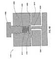
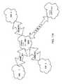
一実施形態では、本発明は、流体を分注する方法を提供する。本実施形態では、本方法は、3つのプロセスを含む。これらのプロセスの1つ目は、弾性可変容積分注チャンバ内に流体をポンピングするステップを含む。分注チャンバは、通常存在する有限流体インピーダンスと吐出口と直列にある。インピーダンスは、流体の一部が吐出口を流動する間も、ポンピングされた流体を受容しながら、分注チャンバの拡張を生じさせるほど十分である。これらのプロセスのもう1つは、分注チャンバの容積に関するパラメータを経時的に繰り返し測定するステップを含む。これらのプロセスの3つ目は、パラメータの反復測定に基づいて、流体のポンピングを制御し、吐出口を流れる所望の流体流動を生じさせるステップを含む。 In one embodiment, the present invention provides a method of dispensing a fluid. In the present embodiment, the method includes three processes. The first of these processes involves pumping fluid into an elastic variable volume dispensing chamber. The dispensing chamber is in series with the normally existing finite fluid impedance and outlet. The impedance is sufficient to cause expansion of the dispensing chamber while receiving the pumped fluid while a portion of the fluid flows through the outlet. Another of these processes involves repeatedly measuring parameters related to the volume of the dispensing chamber over time. The third of these processes involves controlling the pumping of the fluid based on repeated measurement of parameters to produce the desired fluid flow through the outlet.
関連実施形態では、パラメータを繰り返し測定するステップは、音響的に連続する領域内の気体を音響的に励起し、その中に音響応答を生じさせるステップを含む。領域は、分注チャンバに連結されたサブ領域を含むことによって、分注チャンバの容積変化によりサブ領域の容積変化が生じる。また、本実施形態は、音響応答を特徴付けるステップを含む。さらなる関連実施形態では、気体を音響的に励起するステップは、単一周波数のみで行われる。また、音響応答を特徴付けるステップは、音響的に連続する領域内の第1の位置において測定された音響応答と、単一周波数の基準値との位相関係を決定するステップを含む。本実施形態の方法は、位相関係の時間的進化に基づいて、サブ領域の容積変化を計算するステップをさらに含む。 In related embodiments, repeatedly measuring the parameter includes acoustically exciting a gas in an acoustically continuous region and producing an acoustic response therein. The region includes a sub-region connected to the dispensing chamber, so that a volume change of the sub-region occurs due to a volume change of the dispensing chamber. The embodiment also includes the step of characterizing the acoustic response. In a further related embodiment, the step of acoustically exciting the gas is performed at a single frequency only. Also, characterizing the acoustic response includes determining a phase relationship between the acoustic response measured at the first location in the acoustically continuous region and a single frequency reference value. The method of this embodiment further includes calculating a sub-region volume change based on the temporal evolution of the phase relationship.
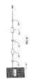
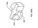
別様または追加として、インピーダンスは、受動インピーダンスである。受動インピーダンスは、随意に、導管を含んでもよい。導管は、いくつかの形態のうちのいずれかを有してもよい。コイル状管を含んでもよい。コイル状管は、少なくとも2つの転換点を含んでもよい。別様または追加として、導管は、蛇行形状を有する。 Alternatively or additionally, the impedance is a passive impedance. The passive impedance may optionally include a conduit. The conduit may have any of several forms. A coiled tube may be included. The coiled tube may include at least two turning points. Alternatively or additionally, the conduit has a serpentine shape.
また、別様または追加として、導管は、流体の粘度および密度のうちの少なくとも1つに基づいて、所定のインピーダンスを提供するように選択された長さと内径とを有する。随意に、内径は、十分な大きさを有し、導管を流れる治療薬の流動による閉塞を防止する。随意に、導管は、2cmを超える長さを有する。 Alternatively or additionally, the conduit has a length and an inner diameter selected to provide a predetermined impedance based on at least one of the viscosity and density of the fluid. Optionally, the inner diameter is sufficiently large to prevent occlusion due to the flow of therapeutic agent flowing through the conduit. Optionally, the conduit has a length greater than 2 cm.
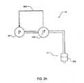
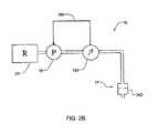
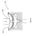
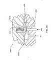
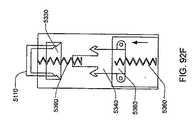
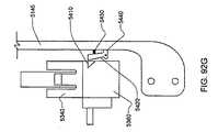
さらなる実施形態では、本方法は、上流流体源と接続可能な注入ラインを提供するステップを含む。注入ラインは、ポンピングチャンバと下流で流体連通する。ポンピングチャンバは、ポンプ吐出口を有する。また、本方法は、加力アセンブリを作動し、注入口への流体の逆流を制限する一方、ポンピングチャンバに加圧し、ポンプ吐出口へ流動を付勢するステップも含む。 In a further embodiment, the method includes providing an injection line connectable with the upstream fluid source. The injection line is in fluid communication downstream with the pumping chamber. The pumping chamber has a pump outlet. The method also includes activating the force assembly to limit fluid backflow to the inlet while pressurizing the pumping chamber and energizing flow to the pump outlet.
関連実施形態では、加力アセンブリを作動するステップは、仕事ストローク間の加力アセンブリの移動を利用して、逆流を制限し、単回機械的作用においてポンピングチャンバに加圧するステップを含む。さらなる関連実施形態では、加力作動アセンブリの所与の移動度によって逆流を制限し、より大きな移動度によってポンピングチャンバに加圧する。 In a related embodiment, actuating the force assembly includes utilizing the movement of the force assembly between work strokes to limit backflow and pressurize the pumping chamber in a single mechanical action. In a further related embodiment, the backflow is limited by a given mobility of the force actuating assembly and pressurized to the pumping chamber by a greater mobility.
さらなる関連実施形態では、加力アセンブリを作動するステップは、注入ラインを閉塞することによって、流体源への逆流を制限するステップを含む。また、別様または追加として、本方法は、間に載置された受動弁を使用して、分注チャンバからポンピングチャンバへの流体の反転流を防止するステップも含む。 In a further related embodiment, actuating the force assembly includes limiting back flow to the fluid source by closing the infusion line. Alternatively or additionally, the method also includes the step of preventing reverse flow of fluid from the dispensing chamber to the pumping chamber using a passive valve mounted therebetween.
別の関連実施形態では、ポンピングされた流体の一部は、例えば、ポンプ吐出口から流体源へ戻るシャントラインを提供することによって、分注チャンバに流入させずに、流体源(例えば、非加圧流体リザーバ)に戻るようにしてもよい。 In another related embodiment, a portion of the pumped fluid does not enter the dispensing chamber, for example by providing a shunt line back from the pump outlet to the fluid source (e.g., non-added). You may make it return to a pressure fluid reservoir.
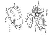
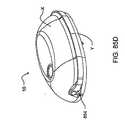
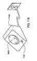
別の関連実施形態では、上述の3つのプロセスは、パッチサイズの筐体内の構成要素によって行われる。筐体は、最大寸法を有し、導管は、最大寸法を超える長さを有する。 In another related embodiment, the three processes described above are performed by components in a patch-sized housing. The housing has a maximum dimension and the conduit has a length that exceeds the maximum dimension.
随意に、導管は、流体の粘度および密度のうちの少なくとも1つに基づいて、所定のインピーダンスを提供するように選択された長さおよび内径を含む。また、随意に、分注チャンバは、注入口を有し、導管は、分注チャンバ注入口の内径よりも小さい内径を有する。 Optionally, the conduit includes a length and an inner diameter selected to provide a predetermined impedance based on at least one of the viscosity and density of the fluid. Also optionally, the dispensing chamber has an inlet and the conduit has an inner diameter that is smaller than the inner diameter of the dispensing chamber inlet.
別の実施形態では、本発明は、流体を分注する装置を提供する。本実施形態では、装置は、パッチサイズの筐体と、筐体内に封入されたポンプと、ポンプと流体連通する、ポンプ下流の分注アセンブリとを含む。分注アセンブリは、弾性分注チャンバと、分注チャンバの容積に関するパラメータまたは時間に対する容積の導関数を定量的に測定するためのセンサとを有する。ポンプは、サイクル毎に弾性分注チャンバを拡張するために、脈動的に流体を排出し、チャンバは、繰り返し流体を出口へ送達する。また、装置は、所望の累積容積を有する流体の送達を達成するように、測定されたパラメータに基づいて、通常流動状態の間のポンプの作動を制御するためのセンサとポンプとに連結された制御ループも含む。ループは、測定されたパラメータに基づいて、出口を通して送達された流体の累積容積を決定する制御装置を含む。 In another embodiment, the present invention provides an apparatus for dispensing fluid. In this embodiment, the apparatus includes a patch-sized housing, a pump enclosed within the housing, and a pump downstream dispensing assembly in fluid communication with the pump. The dispensing assembly includes an elastic dispensing chamber and a sensor for quantitatively measuring a volume related parameter or a derivative of the volume with respect to time. The pump pulsates fluid pulsatingly to expand the elastic dispensing chamber with each cycle, and the chamber repeatedly delivers fluid to the outlet. The device is also coupled to a sensor and a pump for controlling the operation of the pump during normal flow conditions based on the measured parameters to achieve delivery of a fluid having a desired cumulative volume. A control loop is also included. The loop includes a controller that determines the cumulative volume of fluid delivered through the outlet based on the measured parameters.
また、さらなる関連実施形態は、音響的に連続する領域内の気体を音響的に励起し、その中で音響応答を生じさせる音響エネルギ源も含む。領域は、分注チャンバに連結されたサブ領域を含むことによって、分注チャンバの容積変化によりサブ領域の容積変化を生じさせる。さらに、本実施形態は、プロセッサを含み、センサは、音響応答に基づいて電気信号を生成するために、音響的に連続する領域内の第1の位置に載置された第1の音響変換器を含む。プロセッサは、第1の音響変換器と基準値とに連結され、音響応答に基づいて、サブ領域の容積変化に関する量を決定するための流量判断プロセスを実装する。 Further related embodiments also include an acoustic energy source that acoustically excites a gas in an acoustically continuous region and produces an acoustic response therein. The region includes a sub-region coupled to the dispensing chamber, thereby causing a volume change of the sub-region due to a volume change of the dispensing chamber. Furthermore, the present embodiment includes a processor, wherein the sensor is a first acoustic transducer mounted at a first position in an acoustically continuous region to generate an electrical signal based on the acoustic response. including. The processor is coupled to the first acoustic transducer and the reference value and implements a flow determination process for determining an amount related to the volume change of the sub-region based on the acoustic response.
随意に、音響エネルギ源は、単一周波数のみで気体を励起し、第1の音響変換器によって生成された電気信号は、基準値に対する位相関係を有し、さらに流量判断プロセスは、位相関係の時間的進化に基づいて、サブ領域の容積変化に関する量を決定する。 Optionally, the acoustic energy source excites the gas at a single frequency only, the electrical signal generated by the first acoustic transducer has a phase relationship to the reference value, and the flow determination process further Based on temporal evolution, an amount for subregion volume change is determined.
随意に、加えて、本実施形態の装置は、出口に連結された有限流体インピーダンスをさらに含む。インピーダンスは、弾性分注チャンバのそのような拡張を可能にするほど十分である。また、随意に、インピーダンスは、受動インピーダンスである。受動インピーダンスは、随意に、導管を含んでもよい。上述の方法の場合、導管は、いくつかの形態のうちのいずれかを有してもよい。コイル状管を含んでもよい。コイル状管は、少なくとも2つの転換点を含んでもよい。別様または追加として、導管は、蛇行形状を有する。 Optionally, in addition, the apparatus of this embodiment further includes a finite fluid impedance coupled to the outlet. The impedance is sufficient to allow such expansion of the elastic dispensing chamber. Optionally, the impedance is a passive impedance. The passive impedance may optionally include a conduit. For the method described above, the conduit may have any of several forms. A coiled tube may be included. The coiled tube may include at least two turning points. Alternatively or additionally, the conduit has a serpentine shape.
また、別様または追加として、導管は、流体の粘度および密度のうちの少なくとも1つに基づいて、所定のインピーダンスを提供するように選択された長さと内径とを有する。随意に、内径は、十分な大きさを有し、導管を流れる治療薬の流動による閉塞を防止する。随意に、導管は、2cmを超える長さを有する。 Alternatively or additionally, the conduit has a length and an inner diameter selected to provide a predetermined impedance based on at least one of the viscosity and density of the fluid. Optionally, the inner diameter is sufficiently large to prevent occlusion due to the flow of therapeutic agent flowing through the conduit. Optionally, the conduit has a length greater than 2 cm.
さらなる関連実施形態では、筐体は、最大寸法を有し、導管は、最大寸法を超える長さを有する。随意に、分注チャンバは、注入口を有し、導管は、分注チャンバ注入口の内径よりも小さい内径を有する。 In a further related embodiment, the housing has a maximum dimension and the conduit has a length that exceeds the maximum dimension. Optionally, the dispensing chamber has an inlet and the conduit has an inner diameter that is smaller than the inner diameter of the dispensing chamber inlet.
随意に、本発明は、ラインを通して流体をポンピングするためのシステムを提供する。本実施形態では、システムは、流体源と流体連通を提供するための接続可能注入口を有するポンピングチャンバと、ポンプ吐出口を含む。また、システムは、ポンピングチャンバに圧縮ストロークを提供するように適合された加力アセンブリも含む。本実施形態では、圧縮ストロークによって、ポンピングチャンバから注入口への流体の逆流が制限される一方、ポンピングチャンバからポンプ吐出口へ流体を付勢する。 Optionally, the present invention provides a system for pumping fluid through a line. In this embodiment, the system includes a pumping chamber having a connectable inlet for providing fluid communication with a fluid source and a pump outlet. The system also includes a force assembly adapted to provide a compression stroke to the pumping chamber. In this embodiment, the compression stroke limits the back flow of fluid from the pumping chamber to the inlet, while energizing the fluid from the pumping chamber to the pump outlet.
随意に、加力アセンブリは、注入口弁アクチュエータおよびポンプアクチュエータに連結されたことにより、圧縮ストロークが、ポンプアクチュエータによってポンピングチャンバからポンプ吐出口へ流体が付勢されると、注入口と流体源との間に連結された注入口弁を作動し、弁を閉鎖する。 Optionally, the force assembly is coupled to the inlet valve actuator and the pump actuator so that when the compression stroke is energized by the pump actuator from the pumping chamber to the pump outlet, the inlet and fluid source Actuate the inlet valve connected between and close the valve.
随意に、加力アセンブリは、弁アクチュエータと、ポンプアクチュエータと、弁アクチュエータおよびポンプアクチュエータの協調動作のためのモータとに連結されたプレートを含む。随意に、モータは、形状記憶アクチュエータを含む。また、随意に、モータは、形状記憶アクチュエータを折曲し、再利用可能部分内に嵌合するための少なくとも1つの滑車を含む。随意に、加力アセンブリは、モータを含む。 Optionally, the force assembly includes a plate coupled to the valve actuator, the pump actuator, and a motor for coordinated operation of the valve actuator and the pump actuator. Optionally, the motor includes a shape memory actuator. Also optionally, the motor includes at least one pulley for folding the shape memory actuator and fitting within the reusable part. Optionally, the force assembly includes a motor.
追加としてまたは別様に、ポンプの吐出口と流体源(例えば、非加圧流体リザーバ)と流体連通するシャントラインが提供され、ポンプによって排出された流体の一部を流体源に戻すようにしてもよい。 Additionally or alternatively, a shunt line is provided in fluid communication with the pump outlet and a fluid source (eg, a non-pressurized fluid reservoir) so that a portion of the fluid discharged by the pump is returned to the fluid source. Also good.
別の実施形態では、本発明は、流体を分注するための装置を提供し、装置は、パッチサイズの筐体を含む。筐体は、下流の流動阻害歪曲導管と直列の加圧された流体源を封入する。 In another embodiment, the present invention provides an apparatus for dispensing fluid, wherein the apparatus includes a patch-sized housing. The enclosure encloses a pressurized fluid source in series with the downstream flow-inhibiting distorted conduit.
さらなる関連実施形態では、装置は、導管への流体流量に関するパラメータを測定するためのセンサと、測定されたパラメータに基づいて、流体流量を調節するための制御ループとをさらに含む。 In a further related embodiment, the apparatus further includes a sensor for measuring a parameter related to the fluid flow to the conduit and a control loop for adjusting the fluid flow based on the measured parameter.
随意に、源は、動作可能に連結されたポンプを含み、下流の流動阻害歪曲導管に加圧された流体を提供する。また、随意に、装置は、導管への流体流量に関するパラメータを測定するためのセンサと、測定されたパラメータに基づいて、ポンプの動作を調節するための制御ループとを含む。 Optionally, the source includes a pump operably coupled to provide pressurized fluid to the downstream flow-inhibiting distorted conduit. Also optionally, the apparatus includes a sensor for measuring a parameter relating to the fluid flow to the conduit and a control loop for adjusting the operation of the pump based on the measured parameter.
随意に、本発明は、ラインを通して流体をポンピングするためのシステムを提供する。本実施形態では、システムは、流体源と流体連通を提供するための接続可能注入口を有するポンピングチャンバと、ポンプ吐出口を含む。また、システムは、ポンピングチャンバに圧縮ストロークを提供するように適合された加力アセンブリも含む。本実施形態では、圧縮ストロークによって、ポンピングチャンバから注入口への流体の逆流が制限される一方、ポンピングチャンバからポンプ吐出口へ流体を付勢する。 Optionally, the present invention provides a system for pumping fluid through a line. In this embodiment, the system includes a pumping chamber having a connectable inlet for providing fluid communication with a fluid source and a pump outlet. The system also includes a force assembly adapted to provide a compression stroke to the pumping chamber. In this embodiment, the compression stroke limits the back flow of fluid from the pumping chamber to the inlet, while energizing the fluid from the pumping chamber to the pump outlet.
随意に、加力アセンブリは、注入口弁アクチュエータおよびポンプアクチュエータに連結されたことにより、圧縮ストロークが、ポンプアクチュエータによってポンピングチャンバからポンプ吐出口へ流体が付勢されると、注入口と流体源との間に連結された注入口弁を作動し、弁を閉鎖する。 Optionally, the force assembly is coupled to the inlet valve actuator and the pump actuator so that when the compression stroke is energized by the pump actuator from the pumping chamber to the pump outlet, the inlet and fluid source Actuate the inlet valve connected between and close the valve.
随意に、加力アセンブリは、弁アクチュエータと、ポンプアクチュエータと、弁アクチュエータおよびポンプアクチュエータの協調動作のためのモータとに連結されたプレートを含む。随意に、モータは、形状記憶アクチュエータを含む。また、随意に、モータは、形状記憶アクチュエータを折曲し、再利用可能部分内に嵌合するための少なくとも1つの滑車を含む。随意に、加力アセンブリは、モータを含む。 Optionally, the force assembly includes a plate coupled to the valve actuator, the pump actuator, and a motor for coordinated operation of the valve actuator and the pump actuator. Optionally, the motor includes a shape memory actuator. Also optionally, the motor includes at least one pulley for folding the shape memory actuator and fitting within the reusable part. Optionally, the force assembly includes a motor.
追加としてまたは別様に、ポンプの吐出口と流体源(例えば、非加圧流体リザーバ)と流体連通するシャントラインが提供され、ポンプによって排出された流体の一部を流体源に戻すようにしてもよい。 Additionally or alternatively, a shunt line is provided in fluid communication with the pump outlet and a fluid source (eg, a non-pressurized fluid reservoir) so that a portion of the fluid discharged by the pump is returned to the fluid source. Also good.
さらなる関連実施形態では、源は、動作可能に連結された非加圧リザーバをさらに含み、ポンプに流体を提供する。 In further related embodiments, the source further includes a non-pressurized reservoir operably coupled to provide fluid to the pump.
上述の実施形態におけるように、流動阻害歪曲導管は、種々の方法で実装されてもよい。例えば、コイル状であってもよい。少なくとも2つの転換点を含んでもよい。別様または追加として、流動阻害歪曲導管は、蛇行形状を有する。随意に、筐体は、流動阻害歪曲導管を備えた一体型流体路を有する、使い捨て可能な部分を含む。また、随意に、導管は、筐体内に配置される。随意に、導管は、流体の粘度および密度のうちの少なくとも1つに基づいて、所定のインピーダンスを提供するように選択された長さと内径とを有する。随意に、内径は、十分な大きさを有し、導管を流れる治療薬の流動による閉塞を防止する。随意に、導管は、2cmを超える長さを有する。随意に、筐体は、最大寸法を有し、導管は、最大寸法を超える長さを有する。 As in the above-described embodiments, the flow-inhibiting distorted conduit may be implemented in various ways. For example, it may be coiled. It may include at least two turning points. Alternatively or additionally, the flow inhibition distorted conduit has a serpentine shape. Optionally, the housing includes a disposable portion having an integral fluid path with a flow-inhibiting distorted conduit. Also optionally, the conduit is disposed within the housing. Optionally, the conduit has a length and an inner diameter selected to provide a predetermined impedance based on at least one of the viscosity and density of the fluid. Optionally, the inner diameter is sufficiently large to prevent occlusion due to the flow of therapeutic agent flowing through the conduit. Optionally, the conduit has a length greater than 2 cm. Optionally, the housing has a maximum dimension and the conduit has a length that exceeds the maximum dimension.
さらなる関連実施形態では、装置は、追加として、源と導管と流体連通する分注チャンバを含む。分注チャンバは、流体を源から受容する注入口と、流体が導管に提供される吐出口とを含む。随意に、導管は、分注チャンバ注入口の内径よりも小さい内径を有する。 In further related embodiments, the apparatus additionally includes a dispensing chamber in fluid communication with the source and the conduit. The dispensing chamber includes an inlet that receives fluid from the source and an outlet through which fluid is provided to the conduit. Optionally, the conduit has an inner diameter that is smaller than the inner diameter of the dispensing chamber inlet.
別様または追加として、分注チャンバは、弾性可変容積分注チャンバである。随意に、導管は、注入口の有効径よりも小さい有効径を有する。 Alternatively or additionally, the dispensing chamber is an elastic variable volume dispensing chamber. Optionally, the conduit has an effective diameter that is smaller than the effective diameter of the inlet.
随意に、本発明は、ラインを通して流体をポンピングするためのシステムを提供する。本実施形態では、システムは、流体源と流体連通を提供するための接続可能注入口を有するポンピングチャンバと、ポンプ吐出口を含む。また、システムは、ポンピングチャンバに圧縮ストロークを提供するように適合された加力アセンブリも含む。本実施形態では、圧縮ストロークによって、ポンピングチャンバから注入口への流体の逆流が制限される一方、ポンピングチャンバからポンプ吐出口へ流体を付勢する。 Optionally, the present invention provides a system for pumping fluid through a line. In this embodiment, the system includes a pumping chamber having a connectable inlet for providing fluid communication with a fluid source and a pump outlet. The system also includes a force assembly adapted to provide a compression stroke to the pumping chamber. In this embodiment, the compression stroke limits the back flow of fluid from the pumping chamber to the inlet, while energizing the fluid from the pumping chamber to the pump outlet.
随意に、加力アセンブリは、注入口弁アクチュエータおよびポンプアクチュエータに連結されたことにより、圧縮ストロークが、ポンプアクチュエータによってポンピングチャンバからポンプ吐出口へ流体が付勢されると、注入口と流体源との間に連結された注入口弁を作動し、弁を閉鎖する。 Optionally, the force assembly is coupled to the inlet valve actuator and the pump actuator so that when the compression stroke is energized by the pump actuator from the pumping chamber to the pump outlet, the inlet and fluid source Actuate the inlet valve connected between and close the valve.
随意に、加力アセンブリは、弁アクチュエータと、ポンプアクチュエータと、弁アクチュエータおよびポンプアクチュエータの協調動作のためのモータとに連結されたプレートを含む。随意に、モータは、形状記憶アクチュエータを含む。また、随意に、モータは、形状記憶アクチュエータを折曲し、再利用可能部分内に嵌合するための少なくとも1つの滑車を含む。随意に、加力アセンブリは、モータを含む。 Optionally, the force assembly includes a plate coupled to the valve actuator, the pump actuator, and a motor for coordinated operation of the valve actuator and the pump actuator. Optionally, the motor includes a shape memory actuator. Also optionally, the motor includes at least one pulley for folding the shape memory actuator and fitting within the reusable part. Optionally, the force assembly includes a motor.
追加としてまたは別様に、ポンプの吐出口と流体源(例えば、非加圧流体リザーバ)と流体連通するシャントラインが提供され、ポンプによって排出された流体の一部を流体源に戻すようにしてもよい。 Additionally or alternatively, a shunt line is provided in fluid communication with the pump outlet and a fluid source (eg, a non-pressurized fluid reservoir) so that a portion of the fluid discharged by the pump is returned to the fluid source. Also good.
別の実施形態では、本発明は、流体を分注するための装置を提供する。装置は、パッチサイズの筐体と、筐体内に配置されたポンプとを含む。ポンプは、ポンプ吐出口を有する。同様に筐体内に配置される分注チャンバをさらに含む。分注チャンバは、分注注入口と分注吐出口とを有する。分注注入口は、ポンプ吐出口に連結される。また、装置は、分注吐出口に連結された歪曲導管も含み、流動インピーダンスを提供する。 In another embodiment, the present invention provides an apparatus for dispensing fluid. The apparatus includes a patch-sized housing and a pump disposed within the housing. The pump has a pump discharge port. A dispensing chamber is also included that is also disposed within the housing. The dispensing chamber has a dispensing inlet and a dispensing outlet. The dispensing inlet is connected to the pump outlet. The apparatus also includes a distorted conduit connected to the dispensing outlet to provide flow impedance.
随意に、装置は、導管への流体流量に関するパラメータを測定するためのセンサと、測定されたパラメータに基づいて、流体流量を調節するための制御ループとを含む。また、随意に、装置、筐体内に配置され、動作可能に連結された非加圧リザーバをさらに含み、ポンプの注入口に流体を提供する。 Optionally, the apparatus includes a sensor for measuring a parameter related to the fluid flow to the conduit and a control loop for adjusting the fluid flow based on the measured parameter. Optionally, the device further includes a non-pressurized reservoir disposed within the housing and operably coupled to provide fluid to the pump inlet.
前述の実施形態におけるように、歪曲導管は、種々の方法で実装されてもよい。例えば、コイル状であってもよい。少なくとも2つの転換点を含んでもよい。別様または追加として、歪曲導管は、蛇行形状を有する。随意に、導管は、筐体とともに配置される。随意に、筐体は、歪曲導管を備えた一体型流体路を有する、使い捨て可能な部分を含む。随意に、導管は、2cmを超える長さを有する。随意に、筐体は、最大寸法を有し、導管は、最大寸法を超える長さを有する。随意に、導管は、流体の粘度および密度のうちの少なくとも1つに基づいて、所定のインピーダンスを提供するように選択された長さと内径とを有する。随意に、導管は、流体の粘度および密度のうちの少なくとも1つに基づいて、所定のインピーダンスを提供するように選択された長さと内径とを有する。随意に、内径は、十分な大きさを有し、導管を流れる治療薬の流動による閉塞を防止する。 As in the previous embodiment, the distorted conduit may be implemented in various ways. For example, it may be coiled. It may include at least two turning points. Alternatively or additionally, the distorted conduit has a serpentine shape. Optionally, the conduit is disposed with the housing. Optionally, the housing includes a disposable portion having an integral fluid path with a distorted conduit. Optionally, the conduit has a length greater than 2 cm. Optionally, the housing has a maximum dimension and the conduit has a length that exceeds the maximum dimension. Optionally, the conduit has a length and an inner diameter selected to provide a predetermined impedance based on at least one of the viscosity and density of the fluid. Optionally, the conduit has a length and an inner diameter selected to provide a predetermined impedance based on at least one of the viscosity and density of the fluid. Optionally, the inner diameter is sufficiently large to prevent occlusion due to the flow of therapeutic agent flowing through the conduit.
随意に、分注チャンバは、弾性可変容積分注チャンバである。また、随意に、分注チャンバは、注入口を有し、導管は、分注チャンバ注入口の内径よりも小さい内径を有する。 Optionally, the dispensing chamber is an elastic variable volume dispensing chamber. Also optionally, the dispensing chamber has an inlet and the conduit has an inner diameter that is smaller than the inner diameter of the dispensing chamber inlet.
別の実施形態では、本発明は、ラインを通して送達される流体流量を測定するための方法を提供する。本実施形態の方法は、サブ領域の容積に連結された帯域における流体流動によって生じる音響的に連続する領域のサブ領域の容積変化の間、単一周波数のみで音響的に連続する領域内の気体を音響的に励起し、音響応答を生じさせるステップを含む。さらに、本方法は、音響的に連続する領域内の第1の位置において測定された音響応答と、単一周波数の基準値との位相関係を決定するステップと、位相関係の時間的進化に基づいて、サブ領域の容積変化を計算するステップと、サブ領域内の気体の容積変化に基づいて、ラインを流れる流体流量の測定値を推測するステップとを含む。 In another embodiment, the present invention provides a method for measuring fluid flow delivered through a line. The method of this embodiment provides for the gas in an acoustically continuous region only at a single frequency during the volume change of the acoustically continuous region caused by fluid flow in a zone coupled to the volume of the subregion. Is acoustically excited to produce an acoustic response. Further, the method is based on determining a phase relationship between the acoustic response measured at a first location in the acoustically continuous region and a single frequency reference value, and temporal evolution of the phase relationship. And calculating a change in the volume of the sub-region and inferring a measured value of the fluid flow rate through the line based on the volume change of the gas in the sub-region.
随意に、本方法は、音響的に連続する領域内の第2の位置における基準値を測定するステップをさらに含む。また、随意に、帯域は、膜を介してサブ領域の容積に連結される。 Optionally, the method further comprises measuring a reference value at a second position in the acoustically continuous region. Also optionally, the zone is connected to the volume of the sub-region via a membrane.
さらなる関連実施形態では、気体を音響的に励起するステップは、変換器を駆動するステップを含む。随意に、気体を音響的に励起するステップは、スピーカを駆動するステップを含む。本実施形態は、随意に、サブ領域の容積の関数として、位相関係を較正するステップを含む。随意に、音響的に連続する領域は、200マイクロリットル未満の容積を有する。さらなる実施形態では、音響的に連続する領域は、130マイクロリットル未満の容積を有する。別のさらなる実施形態では、音響的に連続する領域は、10マイクロリットル未満の容積を有する。 In a further related embodiment, acoustically exciting the gas includes driving a transducer. Optionally, acoustically exciting the gas includes driving a speaker. This embodiment optionally includes calibrating the phase relationship as a function of sub-region volume. Optionally, the acoustically continuous region has a volume of less than 200 microliters. In a further embodiment, the acoustically continuous region has a volume of less than 130 microliters. In another further embodiment, the acoustically continuous region has a volume of less than 10 microliters.
随意に、容積変化を計算するステップは、20ナノリットルよりも優れた分解能を有するそのような変化を決定するステップを含む。さらなる実施形態では、容積変化を計算するステップは、15ナノリットルよりも優れた分解能を有するそのような変化を決定するステップを含む。さらなる実施形態では、容積変化を計算するステップは、13ナノリットルよりも優れた分解能を有するそのような変化を決定するステップを含む。別のさらなる実施形態では、容積変化を計算するステップは、音響的に連続する領域の容積の少なくとも1/10000の分解能を有するそのような変化を決定するステップを含む。 Optionally, calculating the volume change includes determining such change having a resolution better than 20 nanoliters. In a further embodiment, calculating the volume change includes determining such change having a resolution better than 15 nanoliters. In a further embodiment, calculating the volume change includes determining such a change having a resolution better than 13 nanoliters. In another further embodiment, calculating the volume change comprises determining such a change having a resolution of at least 1/10000 of the volume of the acoustically continuous region.
随意に、単一周波数は、サブ領域の共振周波数であるか、またはそれに近い。 Optionally, the single frequency is at or near the sub-region resonance frequency.
さらなる関連実施形態では、本方法は、一連の周波数で領域を音響的に励起することによって、較正段階を実行し、音響的に連続する領域内の第1の位置において測定された音響応答と、周波数の関数としての一連の周波数のそれぞれの基準値との位相関係を特徴付ける伝達関数を決定するステップをさらに含む。 In a further related embodiment, the method performs a calibration step by acoustically exciting the region at a series of frequencies, and measuring an acoustic response at a first location in the acoustically continuous region; The method further includes determining a transfer function characterizing the phase relationship of each of the series of frequencies as a function of frequency with a respective reference value.
随意に、本方法は、音響的に連続する領域内の第2の位置における一連の周波数のそれぞれの基準値を測定するステップをさらに含む。別様または追加として、本方法は、伝達関数に基づいて、気泡の存在を検出するステップをさらに含む。随意に、本方法は、気泡の存在を検出するステップに基づいて、アラーム状態に入るステップをさらに含む。随意に、容積変化を計算するステップは、測定段階の間、繰り返し行われ、測定段階は、較正段階と交互に行われる。さらなる関連実施形態では、流体は、サイクル毎に送達され、較正および測定段階は、サイクルと協調する。 Optionally, the method further comprises measuring a respective reference value for the series of frequencies at a second location in the acoustically continuous region. Alternatively or additionally, the method further comprises detecting the presence of bubbles based on the transfer function. Optionally, the method further includes entering an alarm condition based on detecting the presence of bubbles. Optionally, the step of calculating the volume change is repeated during the measurement phase, the measurement phase alternating with the calibration phase. In a further related embodiment, the fluid is delivered every cycle and the calibration and measurement phase is coordinated with the cycle.
別の実施形態では、本発明は、ラインを通して送達される流体流量を測定するためのシステムを提供する。本実施形態では、システムは、サブ領域の容積に連結された帯域における流体流動によって生じる音響的に連続する領域のサブ領域の容積変化の間、単一周波数のみで音響的に連続する領域内の気体を音響的に励起し、音響応答を生じさせるための音響エネルギ源を含む。また、システムは、音響応答に基づいて、電気信号を生成するために、音響的に連続する領域内の第1の位置に載置された第1の音響変換器も含む。第1の音響変換器の電気信号は、基準値に対する位相関係を有する。また、システムは、第1の音響変換器と基準値とに連結され、位相関係の時間的進化に基づいて、サブ領域の容積変化に関する量を判断し、サブ領域内の気体の容積変化に基づいて、ラインを流れる流体流量の測定値を推測するための流量判断プロセスを実装するプロセッサも含む。 In another embodiment, the present invention provides a system for measuring fluid flow delivered through a line. In this embodiment, the system is in an acoustically continuous region only at a single frequency during a volume change of the acoustically continuous region caused by fluid flow in a zone coupled to the volume of the subregion. An acoustic energy source for acoustically exciting the gas and producing an acoustic response is included. The system also includes a first acoustic transducer mounted at a first location in an acoustically continuous region to generate an electrical signal based on the acoustic response. The electrical signal of the first acoustic transducer has a phase relationship with respect to the reference value. The system is also coupled to the first acoustic transducer and the reference value, determines an amount related to the volume change of the sub-region based on the temporal evolution of the phase relationship, and based on the volume change of the gas in the sub-region. And a processor that implements a flow determination process for inferring a measurement of the fluid flow through the line.
随意に、システムは、音響的に連続する領域内の第2の位置に載置され、基準値を構成する電気信号を生成するための第2の音響変換器をさらに含む。また、随意に、システムは、1日当たり500ジュール未満の電力消費を有する。 Optionally, the system further includes a second acoustic transducer for generating an electrical signal that is mounted at a second location in an acoustically continuous region and that constitutes a reference value. Also optionally, the system has a power consumption of less than 500 joules per day.
さらなる関連実施形態では、上述の実施形態に従って、ラインを通して送達される流体流量を測定するシステムを利用する、流体送達システムが提供される。本実施形態の流体送達システムは、ラインを通して送達される流体の流動を生じさせ、追加として、プロセッサに連結されたポンプを含む。 In a further related embodiment, a fluid delivery system is provided that utilizes a system that measures fluid flow delivered through a line in accordance with the embodiments described above. The fluid delivery system of this embodiment creates a flow of fluid delivered through the line and additionally includes a pump coupled to the processor.
随意に、本発明は、ラインを通して流体をポンピングするためのシステムを提供する。本実施形態では、システムは、流体源と流体連通を提供するための接続可能注入口を有するポンピングチャンバと、ポンプ吐出口を含む。また、システムは、ポンピングチャンバに圧縮ストロークを提供するように適合された加力アセンブリも含む。本実施形態では、圧縮ストロークによって、ポンピングチャンバから注入口への流体の逆流が制限される一方、ポンピングチャンバからポンプ吐出口へ流体を付勢する。 Optionally, the present invention provides a system for pumping fluid through a line. In this embodiment, the system includes a pumping chamber having a connectable inlet for providing fluid communication with a fluid source and a pump outlet. The system also includes a force assembly adapted to provide a compression stroke to the pumping chamber. In this embodiment, the compression stroke limits the back flow of fluid from the pumping chamber to the inlet, while energizing the fluid from the pumping chamber to the pump outlet.
随意に、加力アセンブリは、注入口弁アクチュエータおよびポンプアクチュエータに連結されたことにより、圧縮ストロークが、ポンプアクチュエータによってポンピングチャンバからポンプ吐出口へ流体が付勢されると、注入口と流体源との間に連結された注入口弁を作動し、弁を閉鎖する。 Optionally, the force assembly is coupled to the inlet valve actuator and the pump actuator so that when the compression stroke is energized by the pump actuator from the pumping chamber to the pump outlet, the inlet and fluid source Actuate the inlet valve connected between and close the valve.
随意に、加力アセンブリは、弁アクチュエータと、ポンプアクチュエータと、弁アクチュエータおよびポンプアクチュエータの協調動作のためのモータとに連結されたプレートを含む。随意に、モータは、形状記憶アクチュエータを含む。また、随意に、モータは、形状記憶アクチュエータを折曲し、再利用可能部分内に嵌合するための少なくとも1つの滑車を含む。随意に、加力アセンブリは、モータを含む。 Optionally, the force assembly includes a plate coupled to the valve actuator, the pump actuator, and a motor for coordinated operation of the valve actuator and the pump actuator. Optionally, the motor includes a shape memory actuator. Also optionally, the motor includes at least one pulley for folding the shape memory actuator and fitting within the reusable part. Optionally, the force assembly includes a motor.
プロセッサによる電力消費は、ポンプによる電力消費を実質的に上回らない。随意に、システムは、帯域をサブ領域の容積に連結する膜をさらに含む。また、随意に、音響エネルギ源は、電気信号に連結された音響変換器を含む。随意に、変換器は、スピーカである。 The power consumption by the processor does not substantially exceed the power consumption by the pump. Optionally, the system further comprises a membrane connecting the zone to the subregion volume. Also optionally, the acoustic energy source includes an acoustic transducer coupled to the electrical signal. Optionally, the transducer is a speaker.
さらなる関連実施形態では、プロセッサは、サブ領域の容積の関数としての位相関係を較正するための較正プロセスを実装する。随意に、音響的に連続する領域は、200マイクロリットル未満の容積を有する。さらなる実施形態では、音響的に連続する領域は、130マイクロリットル未満の容積を有する。別のさらなる実施形態では、音響的に連続する領域は、10マイクロリットル未満の容積を有する。 In a further related embodiment, the processor implements a calibration process for calibrating the phase relationship as a function of sub-region volume. Optionally, the acoustically continuous region has a volume of less than 200 microliters. In a further embodiment, the acoustically continuous region has a volume of less than 130 microliters. In another further embodiment, the acoustically continuous region has a volume of less than 10 microliters.
別様または追加として、流量判断プロセスは、20ナノリットルよりも優れた分解能に対応する、容積変化に関する量を決定する。さらなる実施形態では、流量判断プロセスは、15ナノリットルよりも優れた分解能に対応する、容積変化に関する量を決定する。さらなる実施形態では、流量判断プロセスは、13ナノリットルよりも優れた分解能に対応する、容積変化に関する量を決定する。別のさらなる実施形態では、流量判断プロセスは、音響的に連続する領域の容積の少なくとも1/10000の分解能に対応する、容積変化に関する量を決定する。 Alternatively or additionally, the flow determination process determines an amount related to the volume change that corresponds to a resolution better than 20 nanoliters. In a further embodiment, the flow determination process determines an amount for volume change that corresponds to a resolution better than 15 nanoliters. In a further embodiment, the flow determination process determines an amount related to the volume change that corresponds to a resolution better than 13 nanoliters. In another further embodiment, the flow determination process determines an amount related to volume change that corresponds to a resolution of at least 1/10000 of the volume of the acoustically continuous region.
随意に、単一周波数は、サブ領域の共振周波数であるか、またはそれに近い。さらなる実施形態では、音響源は、プロセッサに連結された音響放射変換器を含む。さらに、プロセッサは、音響源に一連の周波数で領域を音響的に励起させる較正プロセスを実装し、そのようなプロセスの一部として、プロセッサは、第1の変換器の電気信号と、周波数の関数としての一連の周波数のそれぞれの基準値との位相関係を特徴付ける伝達関数を決定する。 Optionally, the single frequency is at or near the sub-region resonance frequency. In a further embodiment, the acoustic source includes an acoustic radiation transducer coupled to the processor. In addition, the processor implements a calibration process that causes the acoustic source to acoustically excite the region at a series of frequencies, and as part of such a process, the processor includes an electrical signal of the first transducer and a function of frequency. A transfer function that characterizes the phase relationship between each of the series of frequencies and the reference value is determined.
さらなる実施形態では、プロセッサは、伝達関数に基づいて、気泡の存在を検出するための気泡検出プロセスを実装する。随意に、気泡検出プロセスは、システムを気泡の存在を検出するステップに基づいて、アラーム状態にさせる。 In a further embodiment, the processor implements a bubble detection process for detecting the presence of bubbles based on the transfer function. Optionally, the bubble detection process causes the system to enter an alarm state based on detecting the presence of bubbles.
さらなる実施形態では、流量判断プロセスは、測定段階の間、繰り返し行われ、測定段階は、較正段階と交互に行われる。随意に、流体は、サイクル毎に送達され、較正および測定段階は、サイクルと協調する。 In a further embodiment, the flow determination process is repeated during the measurement phase, and the measurement phase alternates with the calibration phase. Optionally, fluid is delivered every cycle, and the calibration and measurement phase is coordinated with the cycle.
本発明のこれらの側面は、排他的であることを意味しておらず、本発明の他の特徴、側面、および利点は、添付の請求項および付随の図面と関連させて精読することによって、当業者にとって容易に明白であろう。
例えば、本発明は以下の項目を提供する。
(項目1)
(a)弾性可変容積分注チャンバ内に流体をポンピングするステップであって、上記分注チャンバは、通常存在する有限流体インピーダンスと吐出口と直列にあって、上記インピーダンスは、流体の一部が上記吐出口を流動する間も、ポンピングされた流体を受容しながら、上記分注チャンバの拡張を生じさせるために十分である、ステップと、
(b)上記分注チャンバの容積に関するパラメータを経時的に繰り返し測定するステップと、
(c)上記パラメータの反復測定に基づいて、流体のポンピングを制御し、上記吐出口を通る所望の流体流動を生じさせるステップと
を含む、流体を分注する方法。
(項目2)
上記パラメータを繰り返し測定するステップは、
音響的に連続する領域内の気体を音響的に励起し、上記領域内に音響応答を生じさせるステップであって、上記領域は、上記分注チャンバに連結されたサブ領域を含むことによって、上記分注チャンバの容積変化により上記サブ領域の容積変化を生じさせる、ステップと、
上記音響応答を特徴付けるステップと
を含む、項目1に記載の方法
(項目3)
上記気体を音響的に励起するステップは、単一周波数のみで行われ、上記音響応答を特徴付けるステップは、上記音響的に連続する領域の第1の位置で測定された場合の音響応答と、上記単一周波数の基準値との位相関係を決定するステップを含み、上記方法は、上記位相関係の時間的進化に基づいて、上記サブ領域の容積変化を計算するステップをさらに含む、項目2に記載の方法。
(項目4)
上記インピーダンスは、受動インピーダンスである、項目1に記載の方法。
(項目5)
上記受動インピーダンスは、導管を含む、項目4に記載の方法。
(項目6)
上記導管は、コイル状管を含む、項目5に記載の方法。
(項目7)
上記コイル状管は、少なくとも2つの転換点を含む、項目6に記載の方法。
(項目8)
上記導管は、蛇行形状を有する、項目5に記載の方法。
(項目9)
上記導管は、上記流体の粘度および密度のうちの少なくとも1つに基づいて、所定のインピーダンスを提供するように選択された長さと内径とを有する、項目5に記載の方法。
(項目10)
上記内径は、十分な大きさを有し、上記導管を流れる治療薬の流動による閉塞を防止する、項目9に記載の方法。
(項目11)
上記導管は、2cmを超える長さを有する、項目10に記載の方法。
(項目12)
プロセス(a)、(b)、および(c)は、パッチサイズの筐体内の構成要素によって行われ、上記筐体は、最大寸法を有し、上記導管は、上記最大寸法を超える長さを有する、項目5に記載の方法。
(項目13)
上記導管は、上記流体の粘度および密度のうちの少なくとも1つに基づいて、所定のインピーダンスを提供するように選択された長さを含む、項目5に記載の方法。
(項目14)
上記分注チャンバは、注入口を有し、上記導管は、上記分注チャンバ注入口の内径よりも小さい内径を有する、項目5に記載の方法。
(項目15)
流体をポンピングするステップは、
上流流体源と接続可能な注入ラインを提供するステップであって、上記注入ラインは、ポンピングチャンバと下流で流体連通し、上記ポンピングチャンバは、ポンプ吐出口を有する、ステップと、
加力アセンブリを作動し、上記注入口への流体の逆流を制限しながら、上記ポンピングチャンバに加圧し、上記ポンプ吐出口へ流動を付勢するステップと
を含む、項目1に記載の方法。
(項目16)
上記加力アセンブリを作動するステップは、仕事ストローク間の上記加力アセンブリの移動を利用して、逆流を制限し、単回機械的作用において上記ポンピングチャンバに加圧するステップを含む、項目15に記載の方法。
(項目17)
上記加力作動アセンブリの所与の移動度によって逆流を制限し、より大きな移動度によって上記ポンピングチャンバに加圧する、項目16に記載の方法。
(項目18)
上記加力アセンブリを作動するステップは、上記注入ラインを閉塞することによって、上記流体源への逆流を制限するステップを含む、項目15に記載の方法。
(項目19)
分注チャンバと上記ポンピングチャンバとの間に載置された受動弁を使用して、分注チャンバから上記ポンピングチャンバへの流体の反転流を防止するステップをさらに含む、項目15に記載の方法。
(項目20)
流体をポンピングするステップは、上記流体の一部を上記分注チャンバに流入させずに、流体源に戻ることを可能にするステップをさらに含む、項目1に記載の方法。
(項目21)
パッチサイズの筐体と、
上記筐体内に含まれるポンプと、
上記ポンプと流体連通する、上記ポンプ下流の分注アセンブリであって、上記分注アセンブリは、弾性分注チャンバと、上記分注チャンバの容積に関するパラメータまたは時間に対する上記容積の導関数を定量的に測定するためのセンサとを有し、上記ポンプは、サイクル毎に上記弾性分注チャンバを拡張するために、脈動的に流体を排出し、上記チャンバは、繰り返し流体を出口へ送達する、分注アセンブリと、
所望の累積容積を有する流体の送達を達成するように、上記測定されたパラメータに基づいて、通常流動状態の間の上記ポンプの作動を制御するための上記センサと上記ポンプとに連結された制御ループであって、上記測定されたパラメータに基づいて、上記出口を通して送達された流体の累積容積を決定する制御装置を含む、制御ループと
を含む、流体を分注するための装置。
(項目22)
音響的に連続する領域内で気体を音響的に励起し、該領域内で音響応答を生じさせる音響エネルギ源であって、上記領域は、上記分注チャンバに連結されるサブ領域を含むことによって、上記分注チャンバの容積変化により上記サブ領域の容積変化を生じさせる、音響エネルギ源と、
プロセッサと
をさらに含み、
上記センサは、上記音響的に連続する領域内の第1の位置に載置され、上記音響応答に基づいて、電気信号を生成するための第1の音響変換器を含み、
上記プロセッサは、上記第1の音響変換器と基準値とに連結され、上記音響応答に基づいて、上記サブ領域の容積変化に関する量を決定するための流量判断プロセスを実装する、項目21に記載の装置。
(項目23)
上記音響エネルギ源は、単一周波数のみで上記気体を励起し、上記第1の音響変換器によって生成される上記電気信号は、上記基準値に対し位相関係を有し、上記流量判断プロセスは、上記位相関係の時間的進化に基づいて、上記サブ領域の容積変化に関する量を決定する、項目22に記載の装置。
(項目24)
上記出口に連結された有限流体インピーダンスであって、上記弾性分注チャンバのそのような拡張を可能にするほど十分である、有限流体インピーダンスをさらに含む、項目21に記載の装置。
(項目25)
上記インピーダンスは、受動インピーダンスである、項目24に記載の装置。
(項目26)
上記受動インピーダンスは、導管を含む、項目25に記載の装置。
(項目27)
上記導管は、コイル状管を含む、項目26に記載の装置。
(項目28)
上記コイル状管は、少なくとも2つの転換点を含む、項目27に記載の装置。
(項目29)
上記導管は、蛇行形状を有する、項目26に記載の装置。
(項目30)
上記導管は、上記流体の粘度および密度のうちの少なくとも1つに基づいて、所定のインピーダンスを提供するように選択された長さと内径とを有する、項目26に記載の装置。
(項目31)
上記内径は、十分な大きさを有し、上記導管を流れる治療薬の流動による閉塞を防止する、項目30に記載の装置。
(項目32)
上記導管は、2cmを超える長さを有する、項目31に記載の装置。
(項目33)
上記筐体は、最大寸法を有し、上記導管は、上記最大寸法を超える長さを有する、項目26に記載の装置。
(項目34)
上記分注チャンバは、注入口を有し、上記導管は、上記分注チャンバ注入口の内径よりも小さい内径を有する、項目26に記載の装置。
(項目35)
上記ポンプは、
流体源との流体連通を提供するための接続可能注入口と、ポンプ吐出口とを有するポンピングチャンバと、
圧縮ストロークを上記ポンピングチャンバに提供するように適合された加力アセンブリと
を含み、上記圧縮ストロークによって、上記ポンピングチャンバから上記注入口への流体の逆流を制限しながら、上記ポンピングチャンバから上記ポンプ吐出口へ流体を付勢する、項目21に記載の装置。
(項目36)
上記加力アセンブリが、注入口弁アクチュエータと、ポンプアクチュエータとに連結されることによって、上記ポンプアクチュエータが上記ポンピングチャンバから上記ポンプ吐出口へ流体を付勢する場合、上記圧縮ストロークが、上記注入口と上記流体源との間に連結された注入口弁を作動し、上記弁を閉鎖する、項目35に記載の装置。
(項目37)
上記加力アセンブリは、上記弁アクチュエータと、上記ポンプアクチュエータと、上記弁アクチュエータおよび上記ポンプアクチュエータの協調動作のためのモータとに連結されたプレートを含む、項目36に記載の装置。
(項目38)
上記モータは、形状記憶アクチュエータを含む、項目37に記載の装置。
(項目39)
上記モータは、再利用可能部分内に嵌入するために、上記形状記憶アクチュエータを折曲するための少なくとも1つの滑車を含む、項目38に記載の装置。
(項目40)
上記ポンプの吐出口と流体源と流体連通し、上記ポンプによって排出された上記流体の一部を上記流体源に戻すことが可能なシャントラインをさらに含む、項目21に記載の装置。
(項目41)
上記流体源は、非加圧流体リザーバを含む、項目40に記載の装置。
(項目42)
下流の流動阻害歪曲導管と直列の加圧された流体源を封入する、パッチサイズの筐体を含む、流体を分注するための装置。
(項目43)
上記導管への流体の流量に関するパラメータを測定するためのセンサと、
上記測定されたパラメータに基づいて、上記流体の流量を調節するための制御ループと
をさらに含む、項目42に記載の装置。
(項目44)
上記源は、動作可能に連結されたポンプを含み、上記下流の流動阻害歪曲導管に加圧された流体を提供する、項目42に記載の装置。
(項目45)
上記ポンプは、
流体源との流体連通を提供するように接続可能な注入口と、ポンプ吐出口とを有するポンピングチャンバと、
圧縮ストロークを上記ポンピングチャンバに提供するように適合された加力アセンブリと
を含み、上記圧縮ストロークによって、上記ポンピングチャンバから上記注入口への流体の逆流を制限しながら、上記ポンピングチャンバから上記ポンプ吐出口へ流体を付勢する、項目44に記載の装置。
(項目46)
上記加力アセンブリが、注入口弁アクチュエータと、ポンプアクチュエータとに連結されることによって、上記ポンプアクチュエータが上記ポンピングチャンバから上記ポンプ吐出口へ流体を付勢する場合、上記圧縮ストロークが、上記注入口と上記流体源との間に連結された注入口弁を作動し、上記弁を閉鎖する、項目45に記載の装置。
(項目47)
上記加力アセンブリは、上記弁アクチュエータと、上記ポンプアクチュエータと、上記弁アクチュエータおよび上記ポンプアクチュエータの協調動作のためのモータとに連結されたプレートを含む、項目46に記載の装置。
(項目48)
上記モータは、形状記憶アクチュエータを含む、項目47に記載の装置。
(項目49)
上記モータは、再利用可能部分内に嵌入するために、上記形状記憶アクチュエータを折曲するための少なくとも1つの滑車を含む、項目48に記載の装置。
(項目50)
上記ポンプの吐出口と流体源と流体連通し、上記ポンプによって排出された上記流体の一部を上記流体源に戻すことが可能なシャントラインをさらに含む、項目44に記載の装置。
(項目51)
上記流体源は、非加圧流体リザーバを含む、項目50に記載の装置。
(項目52)
上記導管への流体流量に関するパラメータを測定するためのセンサと
上記測定されたパラメータに基づいて、上記流体流量を調節するための制御ループと
をさらに含む、項目44に記載の装置。
(項目53)
上記源は、動作可能に連結されたポンプを含み、上記下流の流動阻害歪曲導管に加圧された流体を提供する、項目44に記載の装置。
(項目54)
上記流動阻害歪曲導管は、コイル状管を含む、項目42に記載の装置。
(項目55)
上記コイル状管は、少なくとも2つの転換点を含む、項目54に記載の装置。
(項目56)
上記導管は、蛇行形状を有する、項目42に記載の装置。
(項目57)
上記筐体は、上記流動阻害歪曲導管を備える一体型流体路を有する、使い捨て部分を含む、項目42に記載の装置。
(項目58)
上記導管は、上記筐体内に配置される、項目42に記載の装置。
(項目59)
上記導管は、上記流体の粘度および密度のうちの少なくとも1つに基づいて、所定のインピーダンスを提供するように選択された長さと内径とを有する、項目42に記載の装置。
(項目60)
上記内径は、十分な大きさを有し、上記導管を流れる治療薬の流動による閉塞を防止する、項目42に記載の装置。
(項目61)
上記導管は、2cmを超える長さを有する、項目42に記載の装置。
(項目62)
上記筐体は、最大寸法を有し、上記導管は、上記最大寸法を超える長さを有する、項目42に記載の装置。
(項目63)
上記源と上記導管と流体連通し流体を上記源から受容する注入口と、流体が上記導管に提供される吐出口とを備える、分注チャンバをさらに含む、項目42に記載の装置。
(項目64)
上記導管は、上記分注チャンバ注入口の内径よりも小さい内径を有する、項目63に記載の装置。
(項目65)
上記分注チャンバは、弾性可変容積分注チャンバである、項目63に記載の装置。
(項目66)
上記導管は、上記注入口の有効径よりも小さい有効径を有する、項目63に記載の装置。
(項目67)
パッチサイズの筐体と、
上記筐体内に配置され、ポンプ吐出口を有するポンプと、
同様に上記筐体内に配置され、分注注入口と分注吐出口とを有する分注チャンバであって、上記分注注入口は、上記ポンプ吐出口に連結される、分注チャンバと、
上記分注吐出口に連結され、流動インピーダンスを提供する歪曲導管と
を含む、流体を分注するための装置。
(項目68)
上記導管への流体流量に関するパラメータを測定するためのセンサと、
上記測定されたパラメータに基づいて、上記流体流量を調節するための制御ループと、
をさらに含む、項目67に記載の装置。
(項目69)
上記筐体内に配置され、動作可能に連結され、上記ポンプの注入口に流体を提供する、非加圧リザーバをさらに含む、項目67に記載の装置。
(項目70)
上記歪曲導管は、コイル状管を含む、項目67に記載の装置。
(項目71)
上記コイル状管は、少なくとも2つの転換点を含む、項目70に記載の装置。
(項目72)
上記歪曲導管は、蛇行形状を有する、項目67に記載の装置。
(項目73)
上記筐体は、上記歪曲導管を備える一体型流体路を有する、使い捨て可能な部分を含む、項目67に記載の装置。
(項目74)
上記導管は、上記筐体内に配置される、項目67に記載の装置。
(項目75)
上記導管は、2cmを超える長さを有する、項目67に記載の装置。
(項目76)
上記筐体は、最大寸法を有し、上記導管は、上記最大寸法を超える長さを有する、項目67に記載の装置。
(項目77)
上記導管は、上記流体の粘度および密度のうちの少なくとも1つに基づいて、所定のインピーダンスを提供するように選択された有効径を含む、項目67に記載の装置。
(項目78)
上記導管は、上記流体の粘度および密度のうちの少なくとも1つに基づいて、所定のインピーダンスを提供するように選択された長さと内径とを有する、項目67に記載の装置。
(項目79)
上記分注チャンバは、弾性可変容積分注チャンバである、項目67に記載の装置。
(項目80)
上記分注チャンバは、注入口を有し、上記導管は、上記分注チャンバ注入口の内径よりも小さい内径を有する、項目67に記載の装置。
(項目81)
上記ポンプは、
流体源との流体連通を提供するための接続可能注入口と、ポンプ吐出口とを有するポンピングチャンバと、
圧縮ストロークを上記ポンピングチャンバに提供するように適合された加力アセンブリと
を含み、上記圧縮ストロークによって、上記ポンピングチャンバから上記注入口への流体の逆流を制限する一方、上記ポンピングチャンバから上記ポンプ吐出口へ流体を付勢する、項目67に記載の装置。
(項目82)
上記加力アセンブリが、注入口弁アクチュエータと、ポンプアクチュエータとに連結されることによって、上記ポンプアクチュエータが上記ポンピングチャンバから上記ポンプ吐出口へ流体を付勢する場合、上記圧縮ストロークが、上記注入口と上記流体源との間に連結された注入口弁を作動し、上記弁を閉鎖する、項目81に記載の装置。
(項目83)
上記加力アセンブリは、上記弁アクチュエータと、上記ポンプアクチュエータと、上記弁アクチュエータおよび上記ポンプアクチュエータの協調動作のためのモータとに連結されたプレートを含む、項目82に記載の装置。
(項目84)
上記モータは、形状記憶アクチュエータを含む、項目83に記載の装置。
(項目85)
上記モータは、再利用可能部分内に嵌入するために、上記形状記憶アクチュエータを折曲するための少なくとも1つの滑車を含む、項目84に記載の装置。
(項目86)
上記ポンプの吐出口と流体源と流体連通し、上記ポンプによって排出された上記流体の一部を上記流体源に戻すシャントラインをさらに含む、項目67に記載の装置。
(項目87)
上記流体源は、非加圧流体リザーバを含む、項目86に記載の装置。
(項目88)
サブ領域の容積に連結された帯域における流体流動によって生じる音響的に連続する領域のサブ領域の容積変化の間、単一周波数のみで音響的に連続する領域内の気体を音響的に励起し、音響応答を生じさせるステップと、
上記音響的に連続する領域内の第1の位置において測定された上記音響応答と、上記単一周波数の基準値との位相関係を決定するステップと、
上記位相関係の時間的進化に基づいて、上記サブ領域の容積変化を計算するステップと、
上記サブ領域内の気体の上記容積変化に基づいて、上記ラインを流れる流体流量の測定値を推測するステップと
を含む、ラインを通して送達される流体流量を測定するための方法。
(項目89)
上記音響的に連続する領域内の第2の位置における基準値を測定するステップをさらに含む、項目88に記載の方法。
(項目90)
上記帯域は、膜を介して上記サブ領域の上記容積に連結される、項目88に記載の方法。
(項目91)
気体を音響的に励起する上記ステップは、変換器を駆動するステップを含む、項目88に記載の方法。
(項目92)
気体を音響的に励起する上記ステップは、スピーカを駆動するステップを含む、項目88に記載の方法。
(項目93)
上記サブ領域の上記容積の関数として、上記位相関係を較正するステップをさらに含む、項目88に記載の方法。
(項目94)
上記音響的に連続する領域は、200マイクロリットル未満の容積を有する、項目88に記載の方法。
(項目95)
上記音響的に連続する領域は、130マイクロリットル未満の容積を有する、項目88に記載の方法。
(項目96)
上記音響的に連続する領域は、10マイクロリットル未満の容積を有する、項目88に記載の方法。
(項目97)
上記容積変化を計算するステップは、20ナノリットルよりも優れた分解能を有するそのような変化を決定するステップを含む、項目88に記載の方法。
(項目98)
上記容積変化を計算するステップは、15ナノリットルよりも優れた分解能を有するそのような変化を決定するステップを含む、項目88に記載の方法。
(項目99)
上記容積変化を計算するステップは、13ナノリットルよりも優れた分解能を有するそのような変化を決定するステップを含む、項目88に記載の方法。
(項目100)
上記容積変化を計算するステップは、上記音響的に連続する領域の上記容積の少なくとも1/10000の分解能を有するそのような変化を決定するステップを含む、項目88に記載の方法。
(項目101)
上記単一周波数は、上記サブ領域の共振周波数であるか、またはそれに近い、項目88に記載の方法。
(項目102)
一連の周波数で上記領域を音響的に励起することによって、較正段階を実行し、上記音響的に連続する領域内の第1の位置において測定された上記音響応答と、上記周波数の関数としての上記一連の周波数のそれぞれの基準値との位相関係を特徴付ける伝達関数を決定するステップをさらに含む、項目88に記載の方法。
(項目103)
上記音響的に連続する領域内の第2の位置における上記一連の周波数のそれぞれの基準値を測定するステップをさらに含む項目102に記載の方法。
(項目104)
上記伝達関数に基づいて、気泡の存在を検出するステップをさらに含む、項目102に記載の方法。
(項目105)
上記気泡の存在を検出するステップに基づいて、アラーム状態に入るステップをさらに含む、項目104に記載の方法。
(項目106)
上記容積変化を計算するステップは、上記測定段階の間、繰り返し行われ、上記測定段階は、上記較正段階と交互に行われる、項目102に記載の方法。
(項目107)
上記流体は、サイクル毎に送達され、上記較正および測定段階は、上記サイクルと協調する、項目106に記載の方法。
(項目108)
サブ領域の容積に連結された帯域における流体流動によって生じる音響的に連続する領域のサブ領域の容積変化の間、単一周波数のみで音響的に連続する領域内の気体を音響的に励起し、音響応答を生じさせるための音響エネルギ源と、
上記音響的に連続する領域内の第1の位置に載置され、上記音響応答に基づいて、電気信号を生成するための第1の音響変換器であって、上記第1の音響変換器の電気信号は、基準値に対し位相関係を有する、第1の音響変換器と、
上記第1の音響変換器と上記基準値に連結されたプロセッサであって、上記位相関係の時間的進化に基づいて、上記サブ領域の容積変化に関する量を求め、上記サブ領域内の気体の上記容積変化に基づいて、上記ラインを流れる流体流量の測定値を推測するための流量判断プロセスを実装する、プロセッサと
を含む、ラインを通して送達される流体流量を測定するためのシステム。
(項目109)
上記音響的に連続する領域内の第2の位置に載置され、上記基準値を構成する電気信号を生成するための第2の音響変換器をさらに含む、項目108に記載のシステム。
(項目110)
上記システムは、1日当たり500ジュール未満の電力消費を有する、項目108に記載のシステム。
(項目111)
項目108に記載の、ラインを通して送達される流体流量を測定するためのシステムを利用し、上記ラインを通して送達される流体の流動を生じさせる流体送達システムであって、
上記プロセッサに連結されたポンプをさらに含み、
上記プロセッサによる電力消費は、上記ポンプによる電力消費を実質的に上回らない、システム。
(項目112)
上記ポンプは、
流体源との流体連通を提供するための接続可能注入口と、ポンプ吐出口とを有するポンピングチャンバと、
圧縮ストロークを上記ポンピングチャンバに提供するように適合された加力アセンブリと
を含み、上記圧縮ストロークによって、上記ポンピングチャンバから上記注入口への流体の逆流を制限する一方、上記ポンピングチャンバから上記ポンプ吐出口へ流体を付勢する、項目111に記載のシステム。
(項目113)
上記加力アセンブリが、注入口弁アクチュエータと、ポンプアクチュエータとに連結されることによって、上記ポンプアクチュエータが上記ポンピングチャンバから上記ポンプ吐出口へ流体を付勢する場合、上記圧縮ストロークが、上記注入口と上記流体源との間に連結された注入口弁を作動し、上記弁を閉鎖する、項目112に記載のシステム。
(項目114)
上記加力アセンブリは、上記弁アクチュエータと、上記ポンプアクチュエータと、上記弁アクチュエータおよび上記ポンプアクチュエータの協調動作のためのモータとに連結されたプレートを含む、項目113に記載のシステム。
(項目115)
上記モータは、形状記憶アクチュエータを含む、項目114に記載のシステム。
(項目116)
上記モータは、再利用可能部分内に嵌入するために、上記形状記憶アクチュエータを折曲するための少なくとも1つの滑車を含む、項目115に記載のシステム。
(項目117)
上記帯域を上記サブ領域の上記容積に連結する膜をさらに含む、項目108に記載のシステム。
(項目118)
上記音響エネルギ源は、電気信号に連結される音響変換器を含む、項目108に記載のシステム。
(項目119)
上記変換器は、スピーカである、項目108に記載のシステム。
(項目120)
上記プロセッサは、上記サブ領域の上記容積の関数としての上記位相関係を較正するための較正プロセスを実装する、項目108に記載のシステム。
(項目121)
上記音響的に連続する領域は、200マイクロリットル未満の容積を有する、項目108に記載のシステム。
(項目122)
上記音響的に連続する領域は、130マイクロリットル以下の容積を有する、項目108に記載のシステム。
(項目123)
上記音響的に連続する領域は、10マイクロリットル未満の容積を有する、項目108に記載のシステム。
(項目124)
上記流量判断プロセスは、20ナノリットルよりも優れた分解能に対応する容積変化に関する量を決定する、項目108に記載のシステム。
(項目125)
上記流量判断プロセスは、15ナノリットルよりも優れた分解能に対応する容積変化に関する量を決定する、項目108に記載のシステム。
(項目126)
上記流量判断プロセスは、13ナノリットルよりも優れた分解能に対応する容積変化に関する量を決定する、項目108に記載のシステム。
(項目127)
上記流量判断プロセスは、上記音響的に連続する領域の上記容積の少なくとも1/10000の分解能に対応する容積変化に関する量を決定する、項目108に記載のシステム。
(項目128)
上記単一周波数は、上記サブ領域の共振周波数であるか、またはそれに近い、項目108に記載のシステム。
(項目129)
上記音響源は、上記プロセッサに連結された音響放射変換器を含み、
上記プロセッサは、上記音響源に一連の周波数で上記領域を音響的に励起させる較正プロセスを実装し、そのようなプロセスの一部として、上記プロセッサは、上記第1の変換器の電気信号と、上記周波数の関数としての上記一連の周波数のそれぞれの基準値との位相関係を特徴付ける伝達関数を決定する、項目108に記載のシステム。
(項目130)
上記プロセッサは、上記伝達関数に基づいて、気泡の存在を検出する気泡検出プロセスを実装する、項目129に記載のシステム。
(項目131)
上記気泡検出プロセスは、上記気泡の存在を検出するステップに基づいて、上記システムをアラーム状態にさせる項目130に記載のシステム。
(項目132)
上記流量判断プロセスは、上記測定段階の間、繰り返し行われ、上記測定段階は、上記較正段階と交互に行われる、項目131に記載のシステム。
(項目133)
上記流体は、サイクル毎に送達され、上記較正および測定段階は、上記サイクルと協調する、項目132に記載のシステム。These aspects of the invention are not meant to be exclusive, and other features, aspects, and advantages of the present invention will become more apparent when read in conjunction with the appended claims and accompanying drawings. It will be readily apparent to those skilled in the art.
For example, the present invention provides the following items.
(Item 1)
(A) pumping fluid into an elastic variable volume dispensing chamber, wherein the dispensing chamber is in series with a normally present finite fluid impedance and outlet, wherein the impedance is a portion of the fluid Sufficient to cause expansion of the dispensing chamber while receiving the pumped fluid while flowing through the outlet;
(B) repeatedly measuring a parameter relating to the volume of the dispensing chamber over time;
(C) controlling fluid pumping based on repeated measurements of the parameters to produce a desired fluid flow through the outlet;
A method of dispensing a fluid, comprising:
(Item 2)
The step of repeatedly measuring the above parameters is:
Acoustically exciting a gas in an acoustically continuous region to produce an acoustic response in the region, wherein the region includes a sub-region coupled to the dispensing chamber, thereby Causing a change in volume of the sub-region by a change in volume of the dispensing chamber; and
Characterizing the acoustic response; and
The method according to
(Item 3)
The step of acoustically exciting the gas is performed at a single frequency only, and the step of characterizing the acoustic response includes an acoustic response when measured at a first location in the acoustically continuous region, and The method of
(Item 4)
(Item 5)
(Item 6)
6. The method of
(Item 7)
Item 7. The method of item 6, wherein the coiled tube comprises at least two turning points.
(Item 8)
6. The method of
(Item 9)
6. The method of
(Item 10)
10. The method of
(Item 11)
(Item 12)
Processes (a), (b), and (c) are performed by components in a patch-sized housing, the housing having a maximum dimension, and the conduit having a length that exceeds the maximum dimension. 6. The method according to
(Item 13)
6. The method of
(Item 14)
6. The method of
(Item 15)
The step of pumping fluid is
Providing an infusion line connectable to an upstream fluid source, wherein the infusion line is in fluid communication downstream with a pumping chamber, the pumping chamber having a pump outlet;
Activating a force assembly to pressurize the pumping chamber and restrict flow to the pump outlet while limiting back flow of fluid to the inlet;
The method according to
(Item 16)
16. The step of actuating the force assembly includes the step of utilizing the movement of the force assembly between work strokes to limit backflow and pressurize the pumping chamber in a single mechanical action. the method of.
(Item 17)
The method of
(Item 18)
16. The method of
(Item 19)
16. The method of
(Item 20)
The method of
(Item 21)
A patch-sized housing;
A pump included in the housing;
A dispensing assembly downstream of the pump in fluid communication with the pump, the dispensing assembly quantitatively determining an elastic dispensing chamber and a parameter related to the volume of the dispensing chamber or a volume or a derivative of the volume with respect to time; And a pump for pulsating fluid to expand the elastic dispensing chamber every cycle, the chamber repeatedly delivering fluid to the outlet Assembly,
A control coupled to the sensor and the pump for controlling operation of the pump during normal flow conditions based on the measured parameters to achieve delivery of a fluid having a desired cumulative volume. A control loop comprising a controller for determining a cumulative volume of fluid delivered through the outlet based on the measured parameter;
A device for dispensing a fluid, comprising:
(Item 22)
An acoustic energy source that acoustically excites a gas in an acoustically continuous region and produces an acoustic response in the region, the region including a subregion coupled to the dispensing chamber An acoustic energy source that causes a volume change of the sub-region due to a volume change of the dispensing chamber;
With processor
Further including
The sensor is mounted at a first position in the acoustically continuous region and includes a first acoustic transducer for generating an electrical signal based on the acoustic response;
(Item 23)
The acoustic energy source excites the gas at a single frequency only, the electrical signal generated by the first acoustic transducer has a phase relationship to the reference value, and the flow determination process includes:
(Item 24)
(Item 25)
(Item 26)
26. The apparatus of
(Item 27)
27. Apparatus according to item 26, wherein the conduit comprises a coiled tube.
(Item 28)
28. The apparatus of item 27, wherein the coiled tube includes at least two turning points.
(Item 29)
27. Apparatus according to item 26, wherein the conduit has a serpentine shape.
(Item 30)
27. The apparatus of item 26, wherein the conduit has a length and an inner diameter selected to provide a predetermined impedance based on at least one of the viscosity and density of the fluid.
(Item 31)
31. The apparatus of item 30, wherein the inner diameter is sufficiently large to prevent blockage due to the flow of therapeutic agent flowing through the conduit.
(Item 32)
32. The apparatus of
(Item 33)
27. The apparatus of item 26, wherein the housing has a maximum dimension and the conduit has a length that exceeds the maximum dimension.
(Item 34)
27. The apparatus of item 26, wherein the dispensing chamber has an inlet and the conduit has an inner diameter that is smaller than an inner diameter of the dispensing chamber inlet.
(Item 35)
The above pump
A pumping chamber having a connectable inlet for providing fluid communication with a fluid source and a pump outlet;
A force assembly adapted to provide a compression stroke to the pumping chamber;
24. The apparatus of
(Item 36)
When the force assembly is coupled to an inlet valve actuator and a pump actuator so that the pump actuator biases fluid from the pumping chamber to the pump outlet, the compression stroke is greater than the inlet 36. The apparatus of
(Item 37)
38. The apparatus of item 36, wherein the force assembly includes a plate coupled to the valve actuator, the pump actuator, and a motor for coordinated operation of the valve actuator and the pump actuator.
(Item 38)
38. The apparatus of item 37, wherein the motor includes a shape memory actuator.
(Item 39)
39. The apparatus of item 38, wherein the motor includes at least one pulley for folding the shape memory actuator to fit within a reusable part.
(Item 40)
(Item 41)
41. Apparatus according to
(Item 42)
An apparatus for dispensing fluid comprising a patch-sized housing enclosing a pressurized fluid source in series with a downstream flow-inhibiting distorted conduit.
(Item 43)
A sensor for measuring a parameter relating to the flow rate of fluid to the conduit;
A control loop for adjusting the flow rate of the fluid based on the measured parameters;
45. The apparatus of
(Item 44)
43. The apparatus of
(Item 45)
The above pump
A pumping chamber having an inlet connectable to provide fluid communication with a fluid source and a pump outlet;
A force assembly adapted to provide a compression stroke to the pumping chamber;
45. The apparatus of
(Item 46)
When the force assembly is coupled to an inlet valve actuator and a pump actuator so that the pump actuator biases fluid from the pumping chamber to the pump outlet, the compression stroke is greater than the
(Item 47)
49. The apparatus of
(Item 48)
48. The apparatus of item 47, wherein the motor includes a shape memory actuator.
(Item 49)
49. The apparatus of item 48, wherein the motor includes at least one pulley for folding the shape memory actuator to fit within a reusable part.
(Item 50)
45. The apparatus of
(Item 51)
51. A device according to
(Item 52)
A sensor for measuring a parameter relating to the fluid flow to the conduit;
A control loop for adjusting the fluid flow rate based on the measured parameters;
45. The apparatus of
(Item 53)
45. The apparatus of
(Item 54)
43. Apparatus according to
(Item 55)
55. Apparatus according to
(Item 56)
43. Apparatus according to
(Item 57)
43. Apparatus according to
(Item 58)
43. Apparatus according to
(Item 59)
43. The apparatus of
(Item 60)
43. The device of
(Item 61)
43. Apparatus according to
(Item 62)
43. The apparatus of
(Item 63)
43. The apparatus of
(Item 64)
64. The apparatus of item 63, wherein the conduit has an inner diameter that is smaller than an inner diameter of the dispensing chamber inlet.
(Item 65)
64. Apparatus according to item 63, wherein the dispensing chamber is an elastic variable volume dispensing chamber.
(Item 66)
64. Apparatus according to item 63, wherein the conduit has an effective diameter that is smaller than an effective diameter of the inlet.
(Item 67)
A patch-sized housing;
A pump disposed within the housing and having a pump outlet;
Similarly, a dispensing chamber disposed in the housing and having a dispensing inlet and a dispensing outlet, wherein the dispensing inlet is connected to the pump outlet;
A distorted conduit connected to the dispensing outlet and providing flow impedance;
A device for dispensing a fluid, comprising:
(Item 68)
A sensor for measuring a parameter relating to the fluid flow to the conduit;
A control loop for adjusting the fluid flow rate based on the measured parameters;
68. The apparatus of item 67, further comprising:
(Item 69)
68. The apparatus of item 67, further comprising a non-pressurized reservoir disposed within the housing and operably coupled to provide fluid to the inlet of the pump.
(Item 70)
68. Apparatus according to item 67, wherein the distorted conduit comprises a coiled tube.
(Item 71)
71. Apparatus according to item 70, wherein the coiled tube includes at least two turning points.
(Item 72)
68. Apparatus according to item 67, wherein the distorted conduit has a serpentine shape.
(Item 73)
68. The apparatus of item 67, wherein the housing includes a disposable portion having an integral fluid path with the distorted conduit.
(Item 74)
68. Apparatus according to item 67, wherein the conduit is disposed within the housing.
(Item 75)
68. Apparatus according to item 67, wherein the conduit has a length greater than 2 cm.
(Item 76)
68. The apparatus of item 67, wherein the housing has a maximum dimension and the conduit has a length that exceeds the maximum dimension.
(Item 77)
68. The apparatus of item 67, wherein the conduit includes an effective diameter selected to provide a predetermined impedance based on at least one of the viscosity and density of the fluid.
(Item 78)
68. The apparatus of item 67, wherein the conduit has a length and an inner diameter selected to provide a predetermined impedance based on at least one of the viscosity and density of the fluid.
(Item 79)
68. Apparatus according to item 67, wherein the dispensing chamber is an elastic variable volume dispensing chamber.
(Item 80)
68. The apparatus of item 67, wherein the dispensing chamber has an inlet and the conduit has an inner diameter that is smaller than an inner diameter of the dispensing chamber inlet.
(Item 81)
The above pump
A pumping chamber having a connectable inlet for providing fluid communication with a fluid source and a pump outlet;
A force assembly adapted to provide a compression stroke to the pumping chamber;
68. The apparatus of claim 67, wherein the compression stroke limits fluid backflow from the pumping chamber to the inlet while energizing fluid from the pumping chamber to the pump outlet.
(Item 82)
When the force assembly is coupled to an inlet valve actuator and a pump actuator so that the pump actuator biases fluid from the pumping chamber to the pump outlet, the compression stroke is greater than the inlet 82. The apparatus of item 81, wherein the apparatus operates an inlet valve coupled between the fluid source and the fluid source to close the valve.
(Item 83)
83. The apparatus of item 82, wherein the force assembly includes a plate coupled to the valve actuator, the pump actuator, and a motor for coordinated operation of the valve actuator and the pump actuator.
(Item 84)
84. The apparatus according to item 83, wherein the motor includes a shape memory actuator.
(Item 85)
85. The apparatus according to item 84, wherein the motor includes at least one pulley for folding the shape memory actuator to fit within the reusable part.
(Item 86)
68. The apparatus of item 67, further comprising a shunt line in fluid communication with the pump outlet and a fluid source and returning a portion of the fluid discharged by the pump to the fluid source.
(Item 87)
90. Apparatus according to item 86, wherein the fluid source comprises a non-pressurized fluid reservoir.
(Item 88)
During a volume change in a sub-region of an acoustically continuous region caused by fluid flow in a zone coupled to the volume of the subregion, acoustically excites a gas in the acoustically continuous region only at a single frequency Producing an acoustic response; and
Determining a phase relationship between the acoustic response measured at a first location in the acoustically continuous region and a reference value of the single frequency;
Calculating the volume change of the sub-region based on the temporal evolution of the phase relationship;
Inferring a measured value of fluid flow through the line based on the volume change of the gas in the sub-region;
A method for measuring fluid flow delivered through a line.
(Item 89)
90. The method of item 88, further comprising measuring a reference value at a second position within the acoustically continuous region.
(Item 90)
90. The method of item 88, wherein the zone is connected to the volume of the sub-region through a membrane.
(Item 91)
90. A method according to item 88, wherein the step of acoustically exciting the gas comprises driving a transducer.
(Item 92)
90. The method of item 88, wherein the step of acoustically exciting the gas comprises driving a speaker.
(Item 93)
90. The method of item 88, further comprising calibrating the phase relationship as a function of the volume of the sub-region.
(Item 94)
90. The method of item 88, wherein the acoustically continuous region has a volume of less than 200 microliters.
(Item 95)
90. The method of item 88, wherein the acoustically continuous region has a volume of less than 130 microliters.
(Item 96)
90. The method of item 88, wherein the acoustically continuous region has a volume of less than 10 microliters.
(Item 97)
90. The method of item 88, wherein calculating the volume change comprises determining such change having a resolution better than 20 nanoliters.
(Item 98)
90. The method of item 88, wherein calculating the volume change comprises determining such change having a resolution better than 15 nanoliters.
(Item 99)
90. The method of item 88, wherein calculating the volume change comprises determining such change having a resolution better than 13 nanoliters.
(Item 100)
90. The method of item 88, wherein calculating the volume change comprises determining such a change having a resolution of at least 1/10000 of the volume of the acoustically continuous region.
(Item 101)
90. The method of item 88, wherein the single frequency is at or near the resonant frequency of the sub-region.
(Item 102)
A calibration step is performed by acoustically exciting the region at a series of frequencies, the acoustic response measured at a first location in the acoustically continuous region, and the function as a function of the frequency. 90. The method of item 88, further comprising determining a transfer function that characterizes a phase relationship of each of the series of frequencies with each reference value.
(Item 103)
105. The method of
(Item 104)
103. The method of
(Item 105)
105. The method of
(Item 106)
103. A method according to
(Item 107)
109. The method of
(Item 108)
During a volume change in a sub-region of an acoustically continuous region caused by fluid flow in a zone coupled to the volume of the subregion, acoustically excites a gas in the acoustically continuous region only at a single frequency; An acoustic energy source for producing an acoustic response;
A first acoustic transducer mounted at a first position in the acoustically continuous region and for generating an electrical signal based on the acoustic response, the first acoustic transducer comprising: The electrical signal has a first acoustic transducer having a phase relationship with respect to the reference value;
A processor coupled to the first acoustic transducer and the reference value, based on the temporal evolution of the phase relationship, determining an amount related to volume change of the sub-region, and the gas in the sub-region A processor that implements a flow rate determination process to infer a measurement of fluid flow rate through the line based on volume change;
A system for measuring fluid flow delivered through a line.
(Item 109)
109. The system of item 108, further comprising a second acoustic transducer mounted at a second location in the acoustically continuous region and generating an electrical signal that constitutes the reference value.
(Item 110)
109. A system according to item 108, wherein the system has a power consumption of less than 500 joules per day.
(Item 111)
109. A fluid delivery system that utilizes the system for measuring fluid flow delivered through a line as described in item 108 to produce a flow of fluid delivered through the line comprising:
A pump coupled to the processor;
A system wherein power consumption by the processor does not substantially exceed power consumption by the pump.
(Item 112)
The above pump
A pumping chamber having a connectable inlet for providing fluid communication with a fluid source and a pump outlet;
A force assembly adapted to provide a compression stroke to the pumping chamber;
112. The system of claim 111, wherein the compression stroke limits fluid backflow from the pumping chamber to the inlet while energizing fluid from the pumping chamber to the pump outlet.
(Item 113)
When the force assembly is coupled to an inlet valve actuator and a pump actuator so that the pump actuator biases fluid from the pumping chamber to the pump outlet, the compression stroke is greater than the inlet 113. A system according to
(Item 114)
114. The system of item 113, wherein the force assembly includes a plate coupled to the valve actuator, the pump actuator, and a motor for coordinated operation of the valve actuator and the pump actuator.
(Item 115)
115. A system according to item 114, wherein the motor includes a shape memory actuator.
(Item 116)
116. The system of item 115, wherein the motor includes at least one pulley for folding the shape memory actuator to fit within a reusable part.
(Item 117)
109. The system of item 108, further comprising a membrane connecting the zone to the volume of the sub-region.
(Item 118)
109. A system according to item 108, wherein the acoustic energy source includes an acoustic transducer coupled to an electrical signal.
(Item 119)
110. A system according to item 108, wherein the converter is a speaker.
(Item 120)
109. The system of item 108, wherein the processor implements a calibration process for calibrating the phase relationship as a function of the volume of the sub-region.
(Item 121)
109. The system of item 108, wherein the acoustically continuous region has a volume of less than 200 microliters.
(Item 122)
109. The system of item 108, wherein the acoustically contiguous region has a volume of 130 microliters or less.
(Item 123)
109. The system of item 108, wherein the acoustically continuous region has a volume of less than 10 microliters.
(Item 124)
109. The system of clause 108, wherein the flow determination process determines an amount related to volume change that corresponds to a resolution better than 20 nanoliters.
(Item 125)
109. The system of item 108, wherein the flow rate determination process determines an amount related to volume change corresponding to a resolution better than 15 nanoliters.
(Item 126)
109. The system of item 108, wherein the flow rate determination process determines an amount related to volume change that corresponds to a resolution better than 13 nanoliters.
(Item 127)
109. The system of item 108, wherein the flow determination process determines an amount related to volume change corresponding to a resolution of at least 1/10000 of the volume of the acoustically continuous region.
(Item 128)
109. The system of item 108, wherein the single frequency is at or near the resonant frequency of the sub-region.
(Item 129)
The acoustic source includes an acoustic radiation transducer coupled to the processor;
The processor implements a calibration process that causes the acoustic source to acoustically excite the region at a series of frequencies, and as part of such process, the processor includes the electrical signal of the first transducer; 109. The system of item 108, wherein a transfer function characterizing a phase relationship of each of the series of frequencies as a function of the frequency with a reference value is determined.
(Item 130)
130. The system of
(Item 131)
131. The system of
(Item 132)
134. The system of
(Item 133)
135. The system of
本発明の上述の特徴は、付随の図面に関連させて、以下の詳細な説明を参照することによって、より容易に理解されるであろう。
添付の図および本明細書に描写される要素は、必ずしも一貫した縮尺または任意の縮尺で描かれているわけではないことに留意されたい。 It should be noted that the elements depicted in the accompanying drawings and the description are not necessarily drawn to scale or to any scale.
(定義)
本説明および付随の特許請求の範囲で使用されるように、以下の用語は、文脈によって別途要求されない限り、示される意味を有するものとする。(Definition)
As used in this description and the appended claims, the following terms shall have the indicated meanings unless the context requires otherwise.
装置の「ユーザ入力部」は、装置のユーザまたは他のオペレータが装置の機能を制御可能な任意の機構を含む。ユーザ入力部は、機械的配列(例えば、スイッチ、押しボタン)、遠隔制御装置(例えば、RF、赤外線)を備える通信用無線インターフェース、音響式インターフェース(例えば、音声認識を備える)、コンピュータ・ネットワーク・インターフェース(例えば、USBポート)、および他の種類のインターフェースを含んでもよい。 The “user input” of the device includes any mechanism by which the user or other operator of the device can control the functions of the device. User inputs include mechanical arrays (eg, switches, push buttons), communication wireless interfaces with remote controls (eg, RF, infrared), acoustic interfaces (eg, with voice recognition), computer networks, Interfaces (eg, USB ports), and other types of interfaces may be included.
以下に論じられるいわゆる「ボーラスボタン(Bolus button)」等のユーザ入力部の文脈における「ボタン」は、所望の機能を実行可能な任意の種類のユーザ入力部であってもよく、押しボタンに限定されない。 A “button” in the context of a user input, such as the so-called “Bolus button” discussed below, can be any type of user input capable of performing a desired function and is limited to a push button. Not.
「アラーム」は、警告をユーザまたは第三者に発生可能な任意の機構を含む。アラームは、可聴式アラーム(例えば、スピーカ、ブザー、音声発生器)、視覚アラーム(例えば、LED、LCDスクリーン)、触覚アラーム(例えば、振動要素)、無線信号(例えば、遠隔制御装置または介護者への無線伝達)、または他の機構を含んでもよい。アラームは、余剰機構(例えば、2つの異なる聴覚アラーム)または相補機構(例えば、聴覚アラーム、触覚アラーム、および無線アラーム)を含む、同時に、並行して、または順番に、複数の機構を使用して生成されてもよい。 An “alarm” includes any mechanism that can generate a warning to a user or a third party. Alarms can be audible alarms (eg, speakers, buzzers, sound generators), visual alarms (eg, LEDs, LCD screens), tactile alarms (eg, vibration elements), wireless signals (eg, remote control devices or caregivers) Wireless transmission), or other mechanisms. Alarms include redundant mechanisms (eg, two different audible alarms) or complementary mechanisms (eg, audible alarms, tactile alarms, and wireless alarms), using multiple mechanisms simultaneously, in parallel, or in sequence. May be generated.
「流体」は、例えば、流動ラインを通って流動可能な液体等の物質を意味するものとする。 “Fluid” means, for example, a substance such as a liquid that can flow through a flow line.
「インピーダンス」は、そこを流れる流体の流動に対する装置または流動ラインの抵抗(opposition)を意味するものとする。 “Impedance” shall mean the resistance of a device or flow line to the flow of fluid flowing therethrough.
「接液面」は、通常の流体送達動作の間、流体と直接接触する構成要素を表現する。流体は液体に限定されないため、「接液」構成要素は、必ずしも湿潤するわけではない。 “Wetted surface” describes a component that is in direct contact with the fluid during normal fluid delivery operations. Since fluids are not limited to liquids, “wetted” components are not necessarily wetted.
「患者」は、治療の一部または別様であるかにかかわらず、流体送達装置から流体を受ける人物または動物を含む。 A “patient” includes a person or animal that receives fluid from a fluid delivery device, whether part of treatment or otherwise.
「カニューレ」は、流体を患者に注入可能な使い捨て可能な装置を意味するものとする。本明細書で使用されるカニューレは、従来のカニューレまたは針を示し得る。 “Cannula” shall mean a disposable device capable of injecting fluid into a patient. A cannula as used herein may represent a conventional cannula or needle.
「検体センサ」は、患者内の検体の存在を決定可能な任意のセンサを意味するものとする。検体センサの実施形態は、任意のウイルス性、寄生性、細菌性、または化学的検体の存在を決定可能なセンサを含むが、それらに限定されない。用語「検体」は、グルコースを含む。検体センサは、流体送達装置内の他の構成要素(例えば、使い捨て不可能な部分内の制御装置)、および/または遠隔制御装置と通信してもよい。 “Analyte sensor” shall mean any sensor capable of determining the presence of an analyte in a patient. Analyte sensor embodiments include, but are not limited to, sensors capable of determining the presence of any viral, parasitic, bacterial, or chemical analyte. The term “analyte” includes glucose. The analyte sensor may communicate with other components in the fluid delivery device (eg, a control device in a non-disposable part) and / or a remote control device.
「分注アセンブリセンサ」は、分注チャンバ内に存在する流体容積を決定するための機構を意味するものとする。 “Dispensing assembly sensor” shall mean a mechanism for determining the volume of fluid present in a dispensing chamber.
「鋭利部」は、動物の皮膚、特に、ヒトの皮膚に穿刺または突出可能なあらゆるものを意味するものとする。鋭利部は、カニューレ、カニューレ挿入装置、検体センサ、または検体センサ挿入装置を含んでもよい。鋭利部は、個別に提供されてもよく、または、例えば、カートリッジ内等で一緒に提供されてもよい。 "Sharp" shall mean anything that can be pierced or projected into animal skin, in particular human skin. The sharp portion may include a cannula, a cannula insertion device, an analyte sensor, or an analyte sensor insertion device. The sharps may be provided separately or may be provided together, eg, in a cartridge.
「使い捨て可能な」は、固定期間の間に使用され、その後廃棄および交換されることを意図される、部品、装置、部分、またはその他を示す。 “Disposable” refers to a part, device, part, or the like that is used during a fixed period of time and is then intended to be discarded and replaced.
「使い捨て不可能な」は、無期限の使用期間を有することを意図される、再利用可能な部分を示す。 “Non-disposable” refers to a reusable part intended to have an indefinite period of use.
「パッチサイズ」は、装置内に含まれる物質の投与の間、粘着剤またはストラップ等によって、患者の皮膚に固定され、医療装置として装着されるように、固定するために十分小型のサイズであることを意味するものとする。インプラントとして機能するために十分小型の医療装置は、本定義の範囲内である。 “Patch size” is a size that is small enough to be fixed so that it is fixed to a patient's skin and attached as a medical device, such as by an adhesive or strap, during administration of the substance contained within the device. It means that. Medical devices that are small enough to function as an implant are within the scope of this definition.
「通常存在する有限流体インピーダンス」は、流体送達の所定の過程、すなわち、故障状態(例えば、閉塞)が存在しない場合に存在する、有限流体インピーダンスを意味するものとする。 “Normally present finite fluid impedance” shall mean a finite fluid impedance that exists in a given process of fluid delivery, ie, when there is no fault condition (eg, occlusion).
「受動」インピーダンスは、ポンピングサイクルの間、能動的に制御されないものである。 A “passive” impedance is one that is not actively controlled during the pumping cycle.
「音響式容積測定」は、米国特許第5,349,852号および第5,641,892号、ならびに本明細書に記載の技術に説明されるような音響式技術等を使用する、関連容積の定量的測定を意味するものとする。 “Acoustic volume measurement” refers to an associated volume using acoustic techniques such as those described in US Pat. Nos. 5,349,852 and 5,641,892 and the techniques described herein. It shall mean the quantitative measurement of
「温度センサ」は、温度を測定し、温度情報を制御装置に通信するための任意の機構を含む。本装置は、皮膚温度、AVS温度、周囲温度、および流体温度等を測定するための1つ以上の温度センサを含んでもよい。 A “temperature sensor” includes any mechanism for measuring temperature and communicating temperature information to a controller. The apparatus may include one or more temperature sensors for measuring skin temperature, AVS temperature, ambient temperature, fluid temperature, and the like.
本明細書に記載の装置、ポンピング機構、システム、および方法の実施形態は、流体送達に関し、流体のポンピングおよび容積測定、ならびにそれらの作動および制御を含む。装置の実施形態は、流体送達用の携帯型または非携帯型装置を含む。装置の一部の実施形態は、使い捨て可能な基部と、使い捨て不可能なの上部とを含む。装置は、注入装置が基部を通して、直接患者に挿入される実施形態を含む。これらの装置実施形態は、パッチポンプ装置である。パッチポンプは、粘着剤、ストラップ、または他の好適な配列を使用して、患者に接着されてもよい。粘着剤は、使用前に除去し、粘着剤を暴露し得る、保護用剥離可能細片を有してもよい。 Embodiments of the devices, pumping mechanisms, systems, and methods described herein relate to fluid delivery, including fluid pumping and volumetric measurements, and their actuation and control. Device embodiments include portable or non-portable devices for fluid delivery. Some embodiments of the device include a disposable base and a non-disposable top. The device includes embodiments in which the infusion device is inserted directly into the patient through the base. These device embodiments are patch pump devices. The patch pump may be adhered to the patient using an adhesive, strap, or other suitable arrangement. The adhesive may have protective peelable strips that can be removed prior to use to expose the adhesive.
しかしながら、他の実施形態では、流体送達装置は、管が流体ラインに接続される携帯型装置である。管は、典型的には、カニューレを通して患者に接続される。 However, in other embodiments, the fluid delivery device is a portable device where the tube is connected to the fluid line. The tube is typically connected to the patient through a cannula.
使い捨て可能な基部および使い捨て不可能な上部が実装される一部の実施形態では、基部は、接液部品を含み、使い捨て不可能な上部に含まれる部品は、典型的には、非接液部品である。 In some embodiments where a disposable base and a non-disposable top are implemented, the base includes a wetted part, and the part included in the non-disposable top is typically a non-wetted part. It is.
ポンピング機構の種々の実施形態は、上流注入口弁と、ポンピング作動部材、下流出口弁と、可動部材とを含む。一部の実施形態では、ポンピング作動部材および下流弁機能は、同一装置を使用して実装される。ポンピング機構は、リザーバから、流体ラインを通して、出口へと流体をポンピングする。ポンピング機構は、典型的には、非加圧リザーバとともに採用されるが、しかしながら、本発明の範囲は、それに限定されない。 Various embodiments of the pumping mechanism include an upstream inlet valve, a pumping actuating member, a downstream outlet valve, and a movable member. In some embodiments, the pumping actuation member and the downstream valve function are implemented using the same device. The pumping mechanism pumps fluid from the reservoir through the fluid line to the outlet. Pumping mechanisms are typically employed with non-pressurized reservoirs, however, the scope of the present invention is not so limited.
流体送達システムの一実施形態では、本装置は、検体センサ筐体を含む。検体センサは、装置の基部の検体センサ筐体を通して、患者に導入される。これらの実施形態では、注入装置もまた、装置の基部上のカニューレ筐体を通して導入される。これらの実施形態では、本装置は、パッチポンプとしてユーザによって装着される。 In one embodiment of the fluid delivery system, the device includes an analyte sensor housing. The analyte sensor is introduced into the patient through the analyte sensor housing at the base of the device. In these embodiments, the infusion device is also introduced through a cannula housing on the base of the device. In these embodiments, the device is worn by the user as a patch pump.
本システムは、典型的には、無線送受信器を含み得る制御装置を含む。したがって、本装置は、排他的にまたは無線制御装置を部分的に通して、制御されてもよい。制御装置は、検体センサおよび/または流体送達装置から、無線通信を通して情報を受信してもよい。患者または第三者は、制御装置を使用して、流体送達装置の機能を制御可能である。 The system typically includes a controller that may include a wireless transceiver. Thus, the device may be controlled exclusively or partially through the radio controller. The control device may receive information from the analyte sensor and / or fluid delivery device via wireless communication. A patient or a third party can use the control device to control the function of the fluid delivery device.
流体送達装置の一実施形態では、本装置は、インスリンポンプであり、検体センサは、血液グルコースセンサである。送達されるインスリンの容積(または、経時的ポンプストローク数)、および血液グルコースデータの両方に関連する情報を受信する制御装置は、ポンプ機構のための作動スケジュールをプログラムする際に、ユーザを補助する。 In one embodiment of the fluid delivery device, the device is an insulin pump and the analyte sensor is a blood glucose sensor. A controller that receives information related to both the volume of insulin delivered (or the number of pump strokes over time) and the blood glucose data assists the user in programming the operating schedule for the pump mechanism. .
例示的分注アセンブリおよび容積感知装置は、本明細書において説明される。分注アセンブリは、少なくとも1つのマイクロホンと拡声器とを含む。本アセンブリは、分注チャンバ内の容積変化を測定し、ポンピングされる流体容積を決定する。容積感知データは、流体送達装置の状態を決定するために使用される。したがって、種々の制御部は、容積感知データに依存してもよい。 Exemplary dispensing assemblies and volume sensing devices are described herein. The dispensing assembly includes at least one microphone and a loudspeaker. The assembly measures the volume change in the dispensing chamber and determines the fluid volume to be pumped. Volume sensing data is used to determine the state of the fluid delivery device. Thus, the various controls may rely on volume sensing data.
本発明の実施形態では、ユーザは、適切な方法で流体送達装置に流体を送達させるために、ユーザインターフェースを介して、流体送達装置を構成する。一実施形態では、ユーザインターフェースは、パッチと無線通信し得る、別個の携帯用ユーザインターフェースアセンブリ上に存在する。パッチは、使い捨て可能、または部分的に使い捨て可能であってもよい。 In an embodiment of the present invention, the user configures the fluid delivery device via the user interface to cause the fluid delivery device to deliver fluid in an appropriate manner. In one embodiment, the user interface resides on a separate portable user interface assembly that can be in wireless communication with the patch. The patch may be disposable or partially disposable.
本装置の実施形態の例示的使用は、糖尿病患者へのインスリンの送達であるが、上述のように、他の使用として、任意の流体の送達を含む。流体は、有痛者への鎮痛剤、癌患者への化学療法剤、および代謝性疾患を有する患者への酵素を含む。種々の治療流体は、小分子、天然物、ペプチド、タンパク質、核酸、炭水化物、ナノ粒子懸濁液、および関連する製薬学的に許容される担体分子を含んでもよい。治療効果のある分子は、修正し、送達装置内の安定性を向上させてもよい(例えば、ペプチドまたはタンパク質のペグ化によって)。本明細書の実例的実施形態は、薬剤送達用途について記載しているが、本実施形態は、ラボ・オン・チップ用途および毛細管クロマトグラフィ等のハイスループット解析測定用の試薬の液体分注を含む、他の用途に使用されてもよい。以下の説明の目的のため、用語「治療薬」または「流体」は、同じ意味で使用されるが、しかしながら、上述のように、他の実施形態では、任意の流体を使用可能である。したがって、本明細書に含まれる本装置および説明は、治療薬の使用に限定されない。 An exemplary use of embodiments of the device is the delivery of insulin to a diabetic patient, but as mentioned above, other uses include the delivery of any fluid. The fluid includes analgesics for painful individuals, chemotherapeutic agents for cancer patients, and enzymes for patients with metabolic diseases. Various therapeutic fluids may include small molecules, natural products, peptides, proteins, nucleic acids, carbohydrates, nanoparticle suspensions, and related pharmaceutically acceptable carrier molecules. A therapeutically effective molecule may be modified to improve stability within the delivery device (eg, by pegylation of a peptide or protein). Although illustrative embodiments herein describe drug delivery applications, the embodiments include liquid dispensing of reagents for high-throughput analytical measurements such as lab-on-chip applications and capillary chromatography. It may be used for other applications. For purposes of the following description, the terms “therapeutic agent” or “fluid” are used interchangeably, however, as described above, any fluid may be used in other embodiments. Thus, the devices and descriptions contained herein are not limited to the use of therapeutic agents.
典型的な実施形態は、流体の供給量を保持するためのリザーバを含む。インスリンの場合、リザーバは、1日以上の送達用に十分なインスリンを保持するために、便宜的にサイズ調節されてもよい。例えば、リザーバは、約1〜2mlのインスリンを保持してもよい。2mlのインスリンリザーバは、潜在的ユーザの約90%に対し、約3日の供給量に相当し得る。他の実施形態では、リザーバは、任意のサイズまたは形状であることができ、さらに任意の量のインスリンまたは他の流体を保持するように適合されることが可能である。一部の実施形態では、リザーバのサイズおよび形状は、リザーバが保持するように適合される流体の種類に関連する。流体リザーバは、偏心して、または不規則に成形されてもよく、および/または不適当な設置または使用を防止するために、くさび栓で締めてもよい。 An exemplary embodiment includes a reservoir for holding a supply of fluid. In the case of insulin, the reservoir may be conveniently sized to hold enough insulin for delivery for one or more days. For example, the reservoir may hold about 1-2 ml of insulin. A 2 ml insulin reservoir may correspond to a supply of about 3 days for about 90% of potential users. In other embodiments, the reservoir can be of any size or shape and can be adapted to hold any amount of insulin or other fluid. In some embodiments, the size and shape of the reservoir is related to the type of fluid that the reservoir is adapted to hold. The fluid reservoir may be eccentrically or irregularly shaped and / or may be wedged to prevent improper installation or use.
一部の流体送達装置の実施形態は、糖尿病患者による使用用に適合され、したがって、これらの実施形態では、本装置は、患者の膵島ベータ細胞の作用を補完または交換するインスリンを送達する。インスリン送達用に適合された実施形態は、流体送達の基礎レベルならびに送達のボーラスレベルの両方を提供することによって、膵臓の作用を模倣しようとする。基礎レベル、ボーラスレベル、およびタイミングは、無線手持ち式ユーザインターフェースを使用することによって、患者または別の当事者によって設定可能である。さらに、基礎および/またはボーラスレベルは、グルコース監視装置または血液グルコースセンサ等の一体型または外部検体センサの出力に応じて、始動または調節可能である。一部の実施形態では、ボーラスは、流体送達装置上に位置する指定ボタンまたは他の入力手段を使用して、患者または第三者によって始動可能である。さらに他の実施形態では、ボーラスまたは基礎は、流体送達装置上に位置されるユーザインターフェースを通して、プログラムまたは管理可能である。 Some fluid delivery device embodiments are adapted for use by diabetic patients and, therefore, in these embodiments, the device delivers insulin that complements or replaces the action of the patient's islet beta cells. Embodiments adapted for insulin delivery seek to mimic the action of the pancreas by providing both a basal level of fluid delivery as well as a bolus level of delivery. Basal level, bolus level, and timing can be set by the patient or another party by using a wireless handheld user interface. Further, basal and / or bolus levels can be triggered or adjusted in response to the output of an integrated or external analyte sensor such as a glucose monitoring device or a blood glucose sensor. In some embodiments, the bolus can be triggered by the patient or a third party using a designated button or other input means located on the fluid delivery device. In yet other embodiments, the bolus or foundation can be programmed or managed through a user interface located on the fluid delivery device.
図1は、例示的本発明の実施形態に従って、流体送達装置10を装着し、流体送達装置10の動作を監視および調節するための無線ユーザインターフェースアセンブリ14を保持する、患者12を示す。ユーザインターフェースアセンブリ14は、典型的には、情報を入力するための器具(タッチスクリーンまたはキーパッド等)と、ユーザに情報を伝達するための器具(LCDディスプレイ、スピーカ、または振動アラーム等)とを含む。流体送達装置は、典型的には、数日間、快適に患者に接着されたままであるために、十分小型かつ軽量である。 FIG. 1 illustrates a patient 12 wearing a
流体送達装置10は、図1における患者12の腕に装着され示される。他の実施形態では、流体送達装置10は、送達される特定の流体が患者の体によって有利に利用され得る、患者の他の位置に装着されてもよい。例えば、流体は、患者の腹部、腎領域、下肢、またはその他に有利に送達されてもよい。 The
次に、図2Aを参照すると、分注アセンブリ120からポンピングアセンブリ16へのフィードバックループ360を有する、流体送達装置10の略図が示される。ポンピングアセンブリ16は、流体を分注アセンブリ120へポンピングする。次いで、流体は、流量制限器340と出力とを含む出口アセンブリ17へ流出する。出力は、典型的には、カニューレを含み、患者へと通じる。分注アセンブリ120は、弾性可変容積分注チャンバと、少なくとも1つのマイクロホンと、出力を流れる流量に関するパラメータを経時的に測定するための拡声器とを含んでもよい。フィードバックループ360は、センサによって行われる反復測定に基づいて、ポンピングアセンブリ16の動作調節を可能にする。流量制限器340は、分注アセンブリ120と流動ライン5010の出力との間に高インピーダンスを生じさせる。流量制限器340は、例えば、小口径管または微小管の一区画であることが可能である。次に、図2Bを参照すると、一実施形態では、ポンピングアセンブリ16は、リザーバ20から分注アセンブリ120へ流体をポンピングする。 Referring now to FIG. 2A, a schematic diagram of the
次に、図3を参照すると、流体原理を採用する、さらなる実施形態のブロック図が示される。流動ライン310は、リザーバ20と、ポンピングアセンブリ16と、分注アセンブリ120と、出口アセンブリ17とを連結する。出口アセンブリ17は、高インピーダンス流量制限器340と、注入装置5010(例えば、カニューレ)とを含んでもよい。流量制限器340の出力は、患者への送達用に注入装置5010へ送られる。流量制限器340は、分注アセンブリ120上流の流動ライン310の一部よりも、高流動インピーダンスを有する。したがって、ポンピングアセンブリ16は、出口アセンブリ17から流出可能な流体よりも早く、分注アセンブリ120に流体をポンピング可能である。分注アセンブリ120は、弾性壁を有する、可変容積分注チャンバ122を含んでもよい。以下に提示される実施形態では、弾性壁は、膜である。膜材料の実施例は、本明細書に記載のように機能するための所望の弾性および特性を有する、シリコーン、ニトリル、および任意の他の材料を含む。さらに、他の構造が、同一目的を果たすことが可能である。ポンピングアセンブリ16の作用の結果として、一定の流体装填量を受け、膜の弾性によって、初めに、チャンバ122を拡張させ、次いで、分注アセンブリ120の流体含有量を流量制限器340から患者へ通過させるために必要な送達圧を提供させることが可能となる。適切なセンサ(実施例は、以下に記載)が載置される場合、分注アセンブリ120は、可変容積分注チャンバ122を流れる流体の流量を測定してもよく、さらにフィードバックループ360を通してフィードバックを提供して、ポンピングアセンブリ16が、分注チャンバ122にポンピングまたは部分的に充填するタイミングおよび/または速度を制御し、それによって所望の速度で、所望の投与量を患者に送達してもよい。 Referring now to FIG. 3, a block diagram of a further embodiment that employs fluid principles is shown. The
再び、図3を参照すると、さらに、流量制限器340は、指定流速を超える流体流量を防止する。さらに、加圧流体送達は、ポンピングアセンブリ16と、分注アセンブリ120と、流量制限器340との相互作用を通して達成されるため、非加圧リザーバ20を採用することも可能である。 Referring again to FIG. 3, the
さらに図3を参照すると、フィードバックループ360は、制御装置501を含んでもよい。制御装置501は、プロセッサと、ポンピングアセンブリ16を作動し、流体を分注アセンブリ120にポンピングするための制御回路とを含んでもよい。制御装置501は、分注アセンブリ120と一体型であってもよい、センサから流体流量に関するパラメータを繰り返し受信し、本パラメータを使用して、ポンピングアセンブリ16を制御し、出力を流れる所望の流量を達成する。例えば、制御装置501は、ポンピングアセンブリ16のタイミングまたは作動範囲を調節して、所望の基礎あるいはボーラス流速を達成し、および/または所望の基礎あるいはボーラス蓄積投与量を送達可能である。ポンピングのタイミングまたは範囲を決定する際、制御装置501は、センサ(図示せず)の出力を使用して、(とりわけ)流体流速、蓄積流体流量、または両方を推定し、次いで、推定に基づいて、適切な補償作用を決定してもよい。種々の実施形態では、ポンピングは、1パルス当たり10−9リットル〜1パルス当たりマイクロリットルの間で送達可能であるパルスで生じ得る。定常またはボーラス量は、多重パルスを送達することによって達成されてもよい(基礎およびボーラス量の実施例は、以下に提示および記載)。Still referring to FIG. 3, the
部分的に折り畳み式非加圧リザーバ20の使用は、リザーバ内の流体が消耗されるため、リザーバ内の空気の集積を有利に防止し得る。リザーバ20は、隔膜(図示せず)を通して、流体ライン310に接続されてもよい。特に、空洞域が、リザーバ内に含まれる流体とリザーバ20の隔膜との間に介在するように、本システムが傾斜される場合、通気式リザーバ内の空気集積は、リザーバ20からの流体放出を防止可能である。本システムの傾斜は、装着型装置としての通常動作の間、見込まれる。図104〜106Cは、種々の実施形態およびリザーバの一実施形態の図を描写する。また、リザーバのさらなる説明は、以下に含まれる。 The use of a partially collapsible
次に、図4A〜4Cを参照すると、流量制限器340の種々の実施形態が示される。次に、図4Aを参照すると、流量制限器は、成形流動チャネル340であり、基部内の成形溝(図示せず)であってもよい。一実施形態では、成形流動チャネル340の断面は、約0.009インチである。本実施形態では、流量制限器340は、器具に成形される。次に、図4Bを参照すると、極小管340が、代替実施形態の流量制限器として示される。一実施形態では、極小管は、内径約0.009インチを有する。成形流動チャネルと極小管の両方とも、小内径または断面を有する長路を使用して、流動インピーダンスを付与する。次に、図4Cを参照すると、精密孔が、流量制限器340として示される。一実施形態では、精密孔は、レーザードリル穴を備えるプレートである。代替実施形態では、当技術分野で周知の任意の流動インピーダンス装置または方法を使用可能である。 4A-4C, various embodiments of the
概して、機能的に意味において、無限流体インピーダンスを生成すると考えられ得る、能動下流弁を有する先行技術流体送達システムと対照的に、流量制限器340は、有限流体インピーダンスを生成する。また、先行技術システムと対照的に、時々、閉塞によって妨害され得るというよりも、インピーダンスも通常存在する。流体インピーダンスの有限的性質の結果、分注チャンバ122を含む実施形態では、流体は、分注チャンバ122が拡張している際にも、出口から漏出し得る。 In general, in contrast to prior art fluid delivery systems having an active downstream valve that can be considered to produce an infinite fluid impedance in a functional sense, the
図5〜8は、分注アセンブリ120の実例的実施形態の断面図を図式的に示す。産業用プロセス等の他の目的のための流体の送達は、本発明の範囲内であり、特定用語の説明は、一例に過ぎないことを理解されたい。図5に示されるように、分注アセンブリ120は、可変容積分注チャンバ122とセンサ550とを含んでもよい。可変容積分注チャンバ122は、弾性分注ダイヤフラム125を含み、分注アセンブリ120へ流入および流出する流体の流量に応じて、チャンバ122を拡張および収縮させる。本発明のある実施形態では、可変容積分注チャンバ122は、さらに本明細書に記載のように、分注アセンブリ120の他の要素から着脱可能であってもよい。チャンバ122を拡張および収縮させる弾性分注ダイヤフラム125の構想は、両方向矢印によって図示される。計測チャンバ122は、図5において矢印112によって指定される、流体の流動によって特徴付けられるライン110の一部を含むとみなされる。流体の流動112またはライン110の終端位置または性質のいずれも、本明細書に添付の特定の請求項において請求される本発明の範囲を限定する必要はない。流量制限器340は、ポンピングアセンブリ16によってチャンバ122内へポンピングされる場合に、流体がチャンバ122内に流入するよりも、ゆっくりと流体を分注チャンバ122から排出させる。その結果、一定の流体装填量が流入すると、分注チャンバ122は、拡張し、加圧される。分注チャンバ122の拡張により変形される分注ダイヤフラム125は、流量制限器340を通過して出口アセンブリ17へ、計測された容積を送達するために必要とされる力を提供する。上述のように、センサ550は、変位等のパラメータ、あるいは弾性分注チャンバ122の容積に関連し得る熱力学変数または静電容量を繰り返し測定する。センサ550によって生成される容積測定値を使用して、ポンピングアセンブリが、分注チャンバ122に流体をポンピングすることによって、流体の適切な流量が、出口アセンブリ17および後続ラインに、さらにそこから、例えば、患者に送達されるタイミングおよび速度を、フィードバックループを通して制御してもよい。センサ550は、容積または容積関連パラメータを決定するために、例えば、音響式容積感知器(以下に詳述)、または他の方法(他の実施例では、光学、または静電容量)を採用してもよい。音響式容積測定技術は、DEKA Products Limited Partnershipによる米国特許第5,575,310号および第5,755,683号、ならびに2006年4月5日出願の同時係属中の暫定米国特許出願第60/789,243号「METHOD OF VOLUME MEASUREMENT FOR FLOW CONTROL」の主題である(すべて、参照することによって本明細書に援用される)。ナノリットル範囲の流体容積感知器は、本実施形態によって可能であり、したがって、高度に正確かつ精密な監視および送達に貢献する。また、流体流量を測定するための他の代替技術を使用してもよい。例えば、ドップラ法、羽根またはフラッパ弁との組み合わせによるホール効果センサの使用、二重梁の使用(例えば、可撓性の部材の歪曲を感知するための流体チャンバ上の可撓性の部材に関連)、プレートを備えた静電容量感知器の使用、または熱飛行時間法。 5-8 schematically illustrate cross-sectional views of an exemplary embodiment of dispensing
次に、図6から9を参照すると、センサとして音響式容積感知(Acoustic Volume Sensing;AVS)技術を利用する実施形態が示される。第1の議論は、図6および7に描写された実施形態を参照する。分注アセンブリ120は、センサを有する。基準チャンバ127と、ポート128によって、固定容積チャンバ129に連結される可変容積測定チャンバ121とを含む。本発明は、基準チャンバ127によって実践され得るが、図6および7に示されるように、本発明の特定の他の実施形態では、基準容積は、提供されない。容積129は、本明細書では、用語上「固定」と称されるが、固定容積129と称される領域が、スピーカダイヤフラムによって駆動される場合のように、音響励起の時間規模で、実容積は若干変化し得ることを理解されたい。流体は、ポンピングアセンブリ16から流入部123へ、弾性分注チャンバ122を通って、出口チャネル124の外へ流動する。高下流インピーダンスによって、流体が分注チャンバ122に流入すると、分注ダイヤフラム125は、可変容積チャンバ121へ拡張する。プリント基板126上に配列され得る電子アセンブリは、拡声器1202と、感知マイクロホン1203と、可変容積チャンバ121(その容積は、分注ダイヤフラム125の位置によって規定される)内の気体(典型的には、空気)に関連する音響式パラメータを測定するための基準マイクロホン1201とを有する。拡声器134によって誘発される音波は、ポート128を介して、固定容積チャンバ129から可変容積チャンバ121へ移動する。また、音波は、基準チャンバ127へ移動する。分注ダイヤフラム125が、流動ラインを流れる流体の流動とともに運動すると、可変容積チャンバ121内の空気の容積は変化し、その音響特性に関連変化を生じさせる(拡声器およびマイクロホン1203によって検出され得る)。同一音響シミュレーションに対し、基準マイクロホン1201は、固定基準容積127の音響特性を検出してもよい。これらの基準測定値を使用して、例えば、音響シミュレーション、および他のエラーにおいて、不精密性を取り除き、コモンモードの不正確性を阻止してもよい。流体の変位容積は、可変容積チャンバ121の測定容積と、可変容積チャンバ121の初期容積とを比較することによって決定されてもよい。分注チャンバ122および可変容積チャンバ121の総容積は一定であるため、分注チャンバ122の絶対容積もまた、推定可能である。 Referring now to FIGS. 6-9, an embodiment utilizing acoustic volume sensing (AVS) technology as a sensor is shown. The first discussion refers to the embodiment depicted in FIGS.
図6に示される実施形態は、本質的に弾性の分注ダイヤフラム125を利用し、図7に示される実施形態は、分注ダイヤフラム125と結合される場合、分注チャンバ122の弾性を増加させ、図5に示される実施形態において必要とされるものよりも、柔軟性(すなわち、弾性が低い)分注ダイヤフラム125の使用を可能にし得る、弾性分注スプリング130を利用する。分注スプリング130は、典型的には、分注チャンバ122に対向するダイヤフラム125側の分注ダイヤフラム125に隣接して位置付けられる。 The embodiment shown in FIG. 6 utilizes an essentially
代替として、マイクロホンからの背景雑音を低減するために、拡声器1202および感知マイクロホン1203は、別個のポートを介して、可変容積チャンバ121に連結されてもよい。図8に図式的に示されるように、拡声器1202は、拡声器ポート6020を介して、可変容積チャンバ121と音響的に連結される、固定拡声器容積6000内に圧力波を生成する。感知マイクロホン1203によって記録される前に、圧力波は、拡声器1202から、拡声器ポート6020を通して、可変容積チャンバ121へ、次いで、マイクロホンポート6010へ移動する。拡声器ポート6020は、張り出し開口6030を備えた管部分6040を含んでもよい。張り出し開口6030は、均一長を生成する役割を果たし、音波は、それに沿って管部分6040の全軸路に対し移動する。例えば、管部分6040は、直円柱または直円柱体等の円柱形状を有することが可能である。また、同様の張り出し開口を管部分に接合し、マイクロホンポート6010を規定してもよい。図6および7のAVSセンサと対照的に、図8の実施形態では、圧拡声器1202から移動する力波は、感知マイクロホン1203への直接路を有していない。したがって、拡声器1202からの圧力波は、可変容積チャンバ121を最初に通過せずに、直接感知マイクロホン1203に影響を及ぼすことを阻止される。したがって、低背景信号が、マイクロホンによって受信され、優れた信号対雑音比が達成される。さらに、上棚6050を図6〜8の任意の実施形態に含め、有利に、基準チャンバ127の容積を減少させてもよい。 Alternatively,
さらに説明される実施形態では、センサと分注アセンブリの計測チャンバ部分とを分離することによって、分注チャンバが着脱可能かつ使い捨て可能にすることは便宜的であり得る。この場合、分注チャンバは、パッチの使い捨て可能な区分に存在し、センサは、再利用可能区分に存在する。分注チャンバは、弾性流体分注ダイヤフラムによって躍動されてもよい(図6に122および124として示されるように)。代替として、図7のように、分注チャンバ122は、柔軟性ダイヤフラム125によって躍動されてもよい。この場合、分注スプリング130を使用して、分注チャンバ122に弾性を付与することが可能である。センサ550と分注チャンバ122とが接合されると、分注スプリング130は、柔軟性分注ダイヤフラム125を覆う。分注スプリング130および分注ダイヤフラム125は、代替として、分注チャンバ122を規定する単一部品として採用されてもよい。 In further described embodiments, it may be convenient to make the dispensing chamber removable and disposable by separating the sensor and the measurement chamber portion of the dispensing assembly. In this case, the dispensing chamber is in the disposable section of the patch and the sensor is in the reusable section. The dispensing chamber may be driven by an elastofluid dispensing diaphragm (as shown as 122 and 124 in FIG. 6). Alternatively, as in FIG. 7, the dispensing
図9に示されるように、分注アセンブリの代替実施形態が示される。図9に描写される分注アセンブリ120の実施形態では、可変容積測定チャンバ121は、分注チャンバ122と柔軟性壁(ここでは、柔軟性ダイヤフラム125として示される)を共有する。ポート128は、測定チャンバ121を固定容積チャンバ129に音響的に連結し、概して数字1290によって指定される音響的に連続する領域を形成する。圧縮性流体(典型的には、空気、または別の気体)は、音響的に連続する領域1290を充填し、駆動部材1214によって励起される(それ自体は、アクチュエータ1216によって駆動される)。駆動部材1214は、補聴器スピーカ等のスピーカのダイヤフラムであってもよく、アクチュエータ1216は、例えば、音声コイルソレノイドまたは圧電性要素である。本発明の範囲内で、駆動部材1214はまた、アクチュエータ1216と同一の広がりを有してもよく、例えば、駆動部材1214それ自体が圧電性要素であり得る。駆動部材1214は、固定容積129遠位の駆動部材1214側に基準容積1220を含有し得る、駆動装置モジュール1212内に含まれてもよい。しかしながら、基準容積1220は、典型的には、本発明の実践では採用されない。 As shown in FIG. 9, an alternative embodiment of a dispensing assembly is shown. In the embodiment of the dispensing
基準マイクロホン1208は、固定容積129と音響通信するように示され、信号マイクロホン1209は、測定チャンバ121に音響的に連結される。測定領域121の容積は、音響的に連続する領域1290内のそれぞれの位置で測定された圧力変動(または、同等に、音響式信号)に基づいて、1つ以上のマイクロホン1208、1209によって提供される電子信号から決定されてもよい。位相測定は、音響励起の位相に対し、または別のマイクロホン位置における応答位相に対し、1つ以上のマイクロホンにおける応答位相を比較することによって行われてもよい。測定領域121、および含蓄的に、分注チャンバ122の容積は、以下に論じられるように、位相および/または振幅測定に基づいて、プロセッサ1210(代表的には、バッテリとして示される電源1211からの電力を駆動力とする)によって決定される。 The
微量の治療剤の精密送達の目的のため、小量であるが、非常に正確に計測された、ポンプストローク当たり量の送達が望ましい。しかしながら、各ポンプストロークの間、微量の流体が、ライン110を通してポンピングされる場合、非常に高分解能が計測プロセスに必要となる。その結果、本発明の実施形態に従って、容積変化は、少なくとも10ナノリットルの分解能を有するセンサ550によって測定される。測定領域121の分解能0.01%の空容積の測定は、本発明の一部の実施形態において達成されてもよい。本発明の他の実施形態によると、センサ550は、13ナノリットルよりも高い分解能を提供する。さらに他の実施形態では、センサ550は、15ナノリットルよりも高い分解能を提供し、さらなる実施形態では、20ナノリットルよりも高い分解能が提供される。そのような場合、音響的に連続する領域1290の総容積は、130μl未満、さらに他の実施形態では、10μl未満であってもよい。 For the purpose of precision delivery of trace amounts of therapeutic agents, delivery of a small but very accurate metered amount per pump stroke is desirable. However, if a small amount of fluid is pumped through
本発明の種々の実施形態によると、流入部123を通って流入するポンピングされた流体容積による分注チャンバの充填に基づいて、分注チャンバ122、その結果可変容積チャンバ121(本明細書では、「計測容積」とも称される)の容積応答の先験的モデルを使用してもよい。他のモデルも本発明の範囲内であるが、採用され得るモデルの1つは、ポンピングされた流体の流入と固定流動インピーダンスの出力とに応じて、基本容積VBと、ピーク変位VDによって特徴付けられる指数関数的に減衰する容積との合計として、分注チャンバ122内の流体容積を表すことによって、測定の間の計測チャンバ容積は、時間tの関数として、次のように特徴付けられる。According to various embodiments of the present invention, based on the filling of the dispensing chamber with a pumped fluid volume flowing through the

一連の音響式測定に対しモデル化された指数関数的減衰(または他の関数モデル)のパラメタリゼーションに適合するために、図6から9に描写されるようなシステムの応答は、以下のように展開される。応答をモデル化する目的のため、ポート128は、長さlおよび直径dによって特徴付けられる。理想的な断熱気体の圧力および容積は、PVγ=Kによって関連付けられることが可能であり、ここで、Kは、本システムの初期状態によって定義される定数である。
In order to fit the parameterization of the exponential decay (or other functional model) modeled for a series of acoustic measurements, the response of the system as depicted in FIGS. 6-9 evolves as follows: Is done. For the purpose of modeling the response, the
理想気体の法則は、平均圧Pおよび容積V、さらにそれら圧力p(t)に加え、小さな時間依存摂動v(t)を用いて、次のように表され得る。 The ideal gas law can be expressed as follows, using a small time-dependent perturbation v (t) in addition to the mean pressure P and volume V, and also the pressure p (t).
本式を微分すると、次のように求められる。
When this equation is differentiated, it is obtained as follows.
音圧レベルが、周囲圧力よりも非常に低い場合、本式は、さらに次のように簡約され得る。
If the sound pressure level is much lower than the ambient pressure, the equation can be further reduced as follows:
圧力に対し理想気体の法則P=pRTを適用および代入すると、次のように求められる。
Applying and substituting the ideal gas law P = pRT for pressure gives:
これは、音速
This is the speed of sound
を用いて、次のように表され得る。
Can be expressed as follows:
また、容積に対する音響式インピーダンスは、次のように定義される。
Moreover, the acoustic impedance with respect to the volume is defined as follows.
一式のモデルによると、音響式ポートは、ポート内の流体はすべて、本質的に、軸方向に往復運動する剛性円柱に応じて移動すると仮定し、モデル化される。チャネル(ポート128)内の流体はすべて、同一速度で移動すると仮定され、チャネルは、一定断面であると仮定され、チャネルに流入し、チャネルから流出する流体から生じる「終端効果」は、無視される。
According to a set of models, an acoustic port is modeled assuming that all fluid in the port essentially moves in response to a rigid cylinder reciprocating in the axial direction. All fluids in the channel (port 128) are assumed to move at the same speed, the channel is assumed to have a constant cross-section, and the “termination effect” resulting from fluid flowing into and out of the channel is ignored. The
本形式の層流摩擦を This type of laminar friction
と仮定すると、チャネル内の流体の質量に作用する摩擦力は、次のように表され得る:
Assuming that the frictional force acting on the mass of fluid in the channel can be expressed as:
次いで、チャネル内の流体力学に対し、次のように二階微分方程式が表され得る。
A second order differential equation can then be expressed for the fluid dynamics in the channel as follows:
または、容積流量率を用いて、次のように求められる。
Or it calculates | requires as follows using a volumetric flow rate.
次いで、次のようにチャネルの音響式インピーダンスが表され得る。
The acoustic impedance of the channel can then be expressed as follows:
上記で定義された容積およびポート力学を使用して、音響式容積センサシステムが、以下の連立方程式によって表され得る(指数kは、スピーカを示し、rは、共振器を示す)。
Using the volume and port dynamics defined above, an acoustic volume sensor system can be represented by the following simultaneous equations (the index k indicates a speaker and r indicates a resonator).
同一慣例に従って、
According to the same convention,
とすると、次のように求められる。
Then, it is calculated as follows.
さらに、
further,
とすると、次のように求められる。
Then, it is calculated as follows.
p2がp1よりも大きい場合、容積は、正方向に加速する傾向にある。
If p2 is greater than p1, volume tends to accelerate in the forward direction.
式数を削減し(p0を入力として処理)、
Reduce the number of expressions (process with p0 as input),
を代入すると、次のように求められる。
Substituting is obtained as follows.
これらの式を使用して、1つの単純表現式が求められる。
Using these equations, one simple expression is obtained.
また、これらの式は、伝達関数形式で表され得る。「スピーカ間」伝達関数p1/p0は、次のように求められる。
These equations can also be expressed in transfer function form. The “between speakers” transfer function p1 / p0 is determined as follows.
または、
Or
ここで、
here,
である。
It is.
同様に、ポート128の1つの側における測定値に基づく「システム間」伝達関数p2/p0は、次式にて求められる。Similarly, an “intersystem” transfer function p2 / p0 based on measurements on one side of
(システム間位相を使用した容積推定)
同様に、同一原理を使用して、伝達関数が容易に求められ、ポート128を介して連結される可変容積チャンバ121内の圧力を用いて、固定容積チャンバ129内の圧力を表す。特に、伝達関数は、次のように求められる。
(Volume estimation using intersystem phase)
Similarly, using the same principle, the transfer function is easily determined and the pressure in
上述のいずれの場合も、本システムの共振周波数は、次のように可変容積V2の関数として表され得る。
In any of the above cases, the resonant frequency of the system can be expressed as a function of the variable volume V2 as follows:
その他すべてのパラメータが周知であるため、可変容積V2は、例えば、共振周波数に基づいて計算可能であるが、V2を決定する他の方法も有利である場合があり、本願の過程でさらに説明される。本式において定数ではないパラメータの1つは、音速であり、適正温度の知識に基づいて計算される、あるいは別様に求められる、または測定され得る。
Since all other parameters are well known, the variable volume V2 can be calculated, for example, based on the resonant frequency, although other methods of determining V2 may be advantageous, Explained. One parameter that is not a constant in this equation is the speed of sound, which can be calculated based on knowledge of the proper temperature, or otherwise determined or measured.
上述のように、種々の方策を採用し、本システムに尋問することによって、容積V2を求めてもよい。本発明のある実施形態によると、本システムは、駆動部材1214によって、単一周波数で励起される一方、1つ以上の変換器(図9のマイクロホン1208および1209)の応答を監視する。応答は、複合信号として捕捉され、圧力変動の振幅と位相の両方を保有する。チャンバ充満から空の範囲にわたる容積の最大相変化が、それによって達成されるため、中間ストロークにおいて、単一尋問周波数が、本システムの共振に近接して位置することは有利である。As described above, the volume V2 may be determined by employing various strategies and interrogating the system. According to an embodiment of the invention, the system monitors the response of one or more transducers (
信号マイクロホン1208の応答を補正し、励振拡声器1202(図6に図示)または駆動部材1214(図9に図示)の周波数依存特性によるコモンモード効果を阻止してもよい。マイクロホン信号の複素数比として求められる補正信号は、miとして表され得、ここで指数iは、信号の連続時間サンプルを示す。The response of the
同様に、二次機械式ヘルムホルツ共振器に対し伝達関数形式で表すと、信号は、次のように表され得る。 Similarly, when expressed in transfer function form for a second order mechanical Helmholtz resonator, the signal can be expressed as:
ここで、正規化変数が導入され、1のオーダーの計算的有用なダイナミックレンジ内の関連パラメータを維持する。最終式は、公分母上の実数部および虚数部を用いて表される。実数部μの比率を虚数部v(すなわち、位相余接)に当てはめると、次のように求められる。
Here, normalization variables are introduced to maintain relevant parameters within a one order of computationally useful dynamic range. The final expression is expressed using the real part and the imaginary part on the common denominator. When the ratio of the real part μ is applied to the imaginary part v (that is, the phase cotangent), it is obtained as follows.
エラーは、次のように定義され得る。
The error can be defined as follows:
ここで、NおよびDは、それぞれ本モデルの分子と分母を示す。
Here, N and D indicate the numerator and denominator of this model, respectively.
エラーが、各モデルパラメータに対し最小化される場合、最良適合が達成されている。モデルパラメータに適合させるために、任意の方法を採用してもよい。本発明の一実施形態では、勾配降下法が採用され、次のように最小値が求められる。 If the error is minimized for each model parameter, the best fit is achieved. Any method may be employed to adapt to the model parameters. In one embodiment of the present invention, the gradient descent method is employed, and the minimum value is obtained as follows.
各継続時間サンプルが求められる間隔、および時間モデルのパラメータに適合させるためにサンプリングされた間隔数は、本発明の特定の各用途に対し有利に最適化される。定常インスリン送達におけるように、流体がゆっくりではあるが、比較的に定速で流動する場合、τ/3〜3τの期間にかけてサンプリングすることが、有効であることが見いだされている。反対に、比較的に大量の流体のボーラス量が送達される場合、流体は、指数関数的減衰時定数の時間規模に基づいて、ほんの短い間だけ、分注容積チャンバ122内に存在してもよい。その場合、サンプリングは、特性減衰時間の短い割合で行われる。
The interval at which each duration sample is sought and the number of intervals sampled to fit the parameters of the time model are advantageously optimized for each particular application of the present invention. It has been found that sampling over a period of τ / 3 to 3τ is effective when the fluid flows slowly but at a relatively constant rate, as in steady state insulin delivery. Conversely, if a relatively large bolus amount of fluid is delivered, the fluid may be present in dispense
好ましい本発明の実施形態によると、分注容積チャンバ122を通して分注される流体容積は、単調励起周波数で行われるシステム間位相測定を基礎とする、容積対時間モデルに対するフィットに基づいて決定される。図117に示される工程図を参照して、測定プロトコルに関連して次に説明されるように、ポンプストロークの初期部の間、さらに、システム動作を較正するために、予備測定が行われる。概して数字1170によって示される計測プロセスは、有利に、コンピュータ資源を節約し、電力消費を最小限にし、それによって、電源1211(図9に図示)の装填または交換の間の有用な時間を延長する一方、頻繁な較正を通して、上述のストローク当たりの分解能を有する流体の送達に必要とされる測定精度を提供する。 According to a preferred embodiment of the present invention, the volume of fluid dispensed through the dispense
各ポンプストロークに先立って、または1171の開始時のいずれか、あるいは両方において、プロセッサ1210は、AVSシステムの自己較正段階1172を開始する。測定は、測定は、ポンプの起動による電子過渡電流が、実質的に減衰するまで保留される。ステップ1173において、マイクロホンおよびスピーカ増幅率が設定され、一連の周波数で駆動部材1214が作動されるが、典型的には、隣接音響領域1290(別様に、本明細書では、「音響チャンバ」と称される)の共振に略近接する5つの周波数が採用される。6〜8kHzの範囲の周波数が、典型的には採用されるが、任意の周波数の使用も、本発明の範囲内である。各連続周波数の起動開始時、音響過渡電流が実質的に減衰するまで、データ収集は、約5ms間遅延される。 Prior to each pump stroke and / or at the start of 1171, the
約64音響サイクルの間、データは、以下のように収集される。温度センサ132(図70Bに図示)によって提供される温度測定値が、ステップ1174においてサンプリングされ、基準マイクロホン1208に対する信号マイクロホン1209の出力信号比の実数部および虚数部(それぞれpとιで示される)がサンプリングされる。信号の複素数比、または基準マイクロホンに対するマイクロホン信号の他の機能的組み合わせは、AVSシステムを説明する目的のために、本明細書では、「信号」と称される場合がある。 During about 64 acoustic cycles, data is collected as follows. The temperature measurement provided by the temperature sensor 132 (shown in FIG. 70B) is sampled at
周波数当たり約200ms間行われる各周波数における測定に基づいて、各周波数における信号の実数部および虚数部のそれぞれと、温度測定値とに対し、一式の平均値および分散値が求められる。ステップ1175において、これらの値の分析によって、指定境界内にエラーがあるかどうか決定可能となる。異常伝達関数は、マイクロホンまたは他のセンサ、スピーカ、変換器、電子機器、機械的構成要素における故障、流体侵入、粗悪な音響密閉材、過度の周囲雑音、過度の衝撃および振動を含むが、それらに限定されない、システム故障を有利に示し得る。さらに、周波数の関数としての信号位相角の関数依存性は、ステップ1176において決定される。信号位相角、すなわち、その虚数部対実数部の比率の逆正接は、位相の測定として使用され得るが、しかしながら、任意の位相測定も、本発明の範囲内で使用してもよい。関数依存性は、周波数に対する位相の多項式フィットによって、または別様に求められてもよい。多項式フィットに基づいて、または別様に、位相対周波数の傾斜は、容積測定周波数において決定され、容積測定は、ステップ1177において行われる。付加的にかつ有意に、勾配対周波数の異常傾斜は、分注チャンバ122内に含まれる流体の気泡を示す。 Based on measurements at each frequency for about 200 ms per frequency, a set of average and variance values is determined for each of the real and imaginary parts of the signal at each frequency and the temperature measurement. In
各ポンプストロークの後続部分に対し、駆動部材1214は、実質的に単一周波数で作動され、それによって、その周波数で、音響的に連続する領域1290内の気体を音響的に励起する。典型的には、基準マイクロホン1208に対する信号マイクロホン1209の出力信号の複素数比に基づく信号データは、約64サイクルの指定サンプリング間隔にわたって収集および平均化される。信号の実数および虚数部、ならびに温度データは、各サンプリング間隔に対し記録される。サンプリングおよび収集されたデータに基づいて、時間モデルに対してフィットが行われる。本発明の種々の実施形態では、上述のように、各ポンプストロークの際、モデルパラメータ、すなわち、可変容積チャンバ121の基本容積VB、ピーク変位VD、および減衰時間τのフィッティングにおけるエラーを最小限にするために、勾配降下法が採用され、それによって、分注チャンバ122を通して送達される流体容積を提供する。For the subsequent portion of each pump stroke, the
次に、図10を参照すると、分注スプリング130は、ダイヤフラムに対し相補的である渦巻または扇形状を有してもよく、複数のらせん溝131を有してもよい。図示されるスプリングの実施形態は、ダイヤフラムに対し略均等力を加えることが可能である。この略均等力は、ダイヤフラムが拡張する際に、略凹面形状を保持する助けとなる。溝131によって、空気は、スプリングを自由に通過することが可能となり、したがって、空気はほとんど、スプリングとダイヤフラムとの間に補足されることはない。 Next, referring to FIG. 10, the dispensing
次に、図11Aおよび11Bを参照すると、分注チャンバ122(図5に図示)の容積動態測定値、および計算された分注チャンバ122から排出された蓄積容積の実施例が、典型的な定常送達パルス(図11A)および典型的なボーラス送達(図11B)に対し示される。図11Aから分かるように、約2秒間で約0〜約1.5μlとして、音響式容積センサ550によって測定されるように、ポンピングアセンブリ16の作動によって、分注チャンバ122の拡張が生じる。約6秒の半減期(t1/2)によって特徴付けられる指数関数的減衰動態を有する約30秒間にかけて、弾性分注チャンバ122は収縮し、高インピーダンス出力を通してチャンバ122からその流体を排出することが分かる。分注チャンバ122からの出力の蓄積容積は、センサ550によって行われる測定から計算され、また、指数関数的に約1.5μlまで増加することが分かる。高インピーダンス出力は、ポンプアセンブリの作動と、排出される流体の大部分の送達との間に遅延をもたらすことが分かる。本システムのt1/2特性は、分注チャンバ122によって付与される弾性力および出力インピーダンスの程度を考慮して選択可能である。種々の実施形態では、時間定数を変動させ、電力を節約し、ドリフト問題を排除してもよい。時間定数は、例えば、t1/2=2秒、つまりt1/e=2秒であってもよい。Referring now to FIGS. 11A and 11B, an example of the volume dynamics measurement of dispense chamber 122 (shown in FIG. 5) and the accumulated volume discharged from dispense
図11Bは、流体送達装置10による流体のボーラス送達の動態プロファイルを示す。約29回の高速連続ポンプ作動(すなわち、パルス)は、それぞれ流体源から弾性分注チャンバ122へ流体を排出し、したがって、音響式容積測定センサ550によって測定されたパラメータに対応する変化をもたらす。分注チャンバ122の容積は、第1のポンプパルスによって約1.5μlまで拡張し、図11Aにおいて観測される値に類似することが分かる。分注チャンバ122の容積は、分注アセンブリ120の完全放出を達成するために必要な時間よりも短いパルス間隔で、追加脈動ポンピングによってさらに拡張する。拡張は、最大約6μlまで達する。ポンプ脈動の停止は、約85秒後に生じ、チャンバ122の容積は、指数関数的減衰動態に伴って減少し、ポンピング停止後約30秒までに、その含有量の完全放出をもたらすことが分かる。この最終放出のt1/2は、図11Aに示される定常送達に対するものと略同一である。計算された蓄積出力容積は、ポンピングの間、略線形動態で上昇し、ポンピング停止によって停滞状態となることが分かる。FIG. 11B shows a kinetic profile of bolus delivery of fluid by the
記載されたシステムでは、故障状態は、圧力測定によってではなく、容積測定によって検出され、したがって、故障は、数秒で決定され得る。図11C〜11Fは、図5〜7のセンサ550による種々の検出故障状態を示す。図11C〜11Fに対するすべての記載は、図5〜7を参照して説明される。 In the described system, fault conditions are detected by volumetric measurement rather than by pressure measurement, and therefore the fault can be determined in seconds. FIGS. 11C-11F show various detection failure conditions by
図11Cは、正常動作状態下における、センサ550のポンピングパルスの経時的出力動態プロファイルを示す。対照的に、図11Dは、分注アセンブリ120の下流における閉塞の期待される結果を示す。分注チャンバ122内の流体容積の増加(または、非減少)は、センサ550により迅速に検出される。 FIG. 11C shows the output dynamic profile over time of the pumping pulse of
低容積状態は、図11E〜11Fに示される。図11Eでは、略最大センサ信号が達成され、続いて、過度の高速減衰が生じる。本状態は、ポンプ16、ライン310、または分注アセンブリ120内の内部漏出を示し得る。図11Fの動態プロファイルは、低ピーク容積信号を有し、ポンプ故障、空リザーバ20、または分注チャンバ122の上流における閉塞の表象であり得る。また、ポンプ作動に対する分注チャンバ122の遅延拡張は、流動ライン310の問題を示し得る。また、センサ550は、流体内の気泡を検出することが可能であってもよい。アラームは、故障状態の検出に応じて、起動可能である。 The low volume state is shown in FIGS. In FIG. 11E, a substantially maximum sensor signal is achieved, followed by excessive fast decay. This condition may indicate an internal leak in
図12は、音響式容積感知および補償のサイクルを描写する工程図を示す(図2A〜3の制御ループ360に対応する)。センサは、ポンピングサイクルによって誘発される、可変容積チャンバ121内のサイクル変化の規模の測定に基づいて、装置10から分注される流体の量を測定してもよい。例えば、センサ550は、共振可変容積121および基準容積チャンバ127の音響スペクトルを繰り返し取得し(ステップ2611)、パラメータ(各ポンピングパルスに対して更新され、可変容積チャンバ121内の気体の容積の減少を組み込む)を維持してもよい。 FIG. 12 shows a process diagram depicting the acoustic volume sensing and compensation cycle (corresponding to the
故に、更新されたパラメータは、分注チャンバ122に流入した流体の正味量を示す。パルス間に十分な遅延がある場合、分注チャンバ122に流入する流体は、装置10によって分注された容積に略等しい。代替として、センサ550は、可変容積チャンバ121内の気体の容積の増加を繰り返し測定し、本装置によって分注される量を決定することが可能である(パルス間に十分な遅延がある場合)。音響スペクトルは、気泡有り、気泡無し、または様々なサイズの気泡を有する、分注チャンバ122の一部または全部に対応し得る、参照テーブル内のモデルスペクトルと比較される(ステップ2621)。参照テーブルは、実験的に取得、モデルを使用して決定、または経験的に作用すると決定されたデータを保有してもよい。参照テーブルは、分注チャンバ122の多拡張度に対し、様々な気泡含有状態および/または正常状態を表すデータを含んでもよい。スペクトルおよび更新合計値が、正常流動モデルに適合する場合(ステップ2631)、ステップ2611において、別の音響スペクトルが取得され、サイクルが繰り返される。スペクトルおよび/または更新合計値が、正常流動モデルに適合しない場合、低流または閉塞流の存在が決定される(ステップ2641)。低流または閉塞流は、可変容積チャンバ121の持続的範囲外容積によって、予測値または設定値を下回る更新合計値によって、または両方によって示され得る。低流または閉塞流状態が検出されると、アラームが始動される(ステップ2671)。アラームは、可聴式信号、振動、または両方を含んでもよい。低流または閉塞流状態が見つからない場合、装置は、スペクトルが分注チャンバ122内の気泡の状態に対応するモデルに適合するかどうか決定する(ステップ2661)。気泡が存在すると決定されると、一時的にポンピング率を増加させるステップを含んでもよい、アラームおよび/または補償作用を含み得る応答が開始され(ステップ2651)、ステップ2611において、サイクルが再開される。気泡が存在しないと決定される場合、アラームが始動し、不明故障状態を示す(ステップ2671)。また、本発明の実施形態は、同時係属米国特許出願第60/789,243号(参照することによって、本明細書に援用される)に開示されるようなAVS技術を使用する気泡検出を利用してもよい。 Thus, the updated parameter indicates the net amount of fluid that has entered the dispensing
図2A〜3のポンピングアセンブリ16は、リザーバ20から分注アセンブリ120へ流体を付勢する。図6〜7による分注アセンブリが使用される場合、分注アセンブリ120からポンピングアセンブリ16へ提供されるフィードバックによって、送達される容積の正確な測定に基づくポンピングアセンブリ16の調節が可能となるため、高精密ポンプを使用する必要はない。個々のポンピングパルスは、フィードバックに基づいて精密補償が可能となるように、十分に低容量であってもよい。したがって、多くの異なるポンピングアセンブリ16の実装を採用することが可能である。ポンピングアセンブリ16の種々の可能な実施形態は、後述される。 The pumping
図13および14は、本発明の実施形態による、流体送達装置内の一部の構成要素の代替実施形態を図式的に示す。図13は、上流の一方向弁21と下流の一方向弁22との間に位置されるポンピング要素2100を有するポンピングアセンブリ16を備えた、流動ライン310を示す。ポンピング要素2100は、アクチュエータを使用して、流動ラインの一部を変形させ、流動ライン310内に圧力を生成してもよい。上流の一方向弁21は、ポンピング要素2100から流体源(図示せず)への逆流を阻止し、下流の一方向弁22は、容積感知チャンバ120からポンピング要素2100への逆流を阻止する。その結果、流体は、出口アセンブリ17の方向へ駆動され、一実施形態では、高インピーダンス路を含む。 Figures 13 and 14 schematically illustrate alternative embodiments of some components within a fluid delivery device, according to embodiments of the present invention. FIG. 13 shows a
図14に示される代替実施形態では、ポンピング要素の機能、すなわち、流動ライン310内に圧力を生成する機能と、上流の一方向弁21の機能は、結合弁ポンプ2200によって行われる。したがって、図14の実施形態のポンピングアセンブリ16は、図13の実施形態で使用される3つの構成要素の代わりに、2つの構成要素(つまり、結合弁ポンプ2200および下流一方向弁22)から成る。ポンピングアセンブリ16の他の実施形態を使用してもよい。弁ポンプ2200内の弁機能とポンピング機能との組み合わせは、種々の機構によって達成されてもよく、一部は、図15A〜16および22〜56を参照して後述される。 In the alternative embodiment shown in FIG. 14, the function of the pumping element, ie, the function of generating pressure in the
後述される多くの実施形態では、注入口弁21のポペットと、出口弁22のポペットと、ポンピング作動部材54とは、すべて直接的または間接的に(例えば、図50〜56のように)流体ライン310と連通することによって、これらの要素のそれぞれが、種々の流体圧を生成またはそれに対し反応可能となる。上述のように、上流および下流弁(本明細書では、注入口および出口弁と称される場合がある)は、一方向弁である。弁は、他の種類の一方向弁、つまり流動を装置出力へバイアスする他の種類の弁の中でも、噴火口状弁、フラップ弁、逆止弁、またはダックビル弁であることが可能である。噴火口状弁の実施例は、1993年1月12日にDean L.Kamenに発行された米国出願第5,178,182号に開示される(参照することによって、本明細書に援用される)。 In many embodiments described below, the poppet of the
図15A〜15Dに示される実施形態では、ポンピングアセンブリは、注入口弁21と出口弁22との両方を含み、それぞれ、流体注入口と、流体出口と、可動部材(各弁のための、膜2356の一部)とを含む。また、ポンピングアセンブリは、ポンピング要素2100も含む。ポンピング要素は、注入口弁21から下流方向と、出口弁22から上流方向とに位置する。以下の説明では、出口弁は、閉位置、すなわち、流体が出口弁へと流動しない位置から開始する。しかしながら、流体が十分な圧力を呈する場合、膜および出口弁のポペット9221に弁を開放するための圧力が印加されることによって、流体圧によって出口弁が開放され、したがって、流体は、出口弁22へ流動可能となる。図15Aから15Dの実施形態は、単一機械的作用によって、ポンプ注入口を閉塞し、次いで、ポンプ吐出口へ流動を付勢するという意味では、結合弁ポンプ(図14の要素2200等)であるとみなされてもよい。 In the embodiment shown in FIGS. 15A-15D, the pumping assembly includes both an
このポンピング配列は、可動部品と接液ライン構成要素とを、可撓性の障壁膜2356の対側に分割する利点を有する。その結果、可動部品は、再利用可能な構成要素内に位置し、接液部品(流体ライン310)は、使い捨て可能な構成要素内に位置され得る。 This pumping arrangement has the advantage of dividing the moving parts and the wetted line components on the opposite side of the
ポンピング機構の好ましい実施形態では、流体源は、非加圧リザーバである。注入口弁の可動部材が開位置にあり、ポンピングチャンバ内に陰圧が存在する場合、リザーバから注入口弁への流体を引き寄せる圧力差が存在する。この陰圧は、ポンピングチャンバ内の膜の弾性によって生じ得る。一代替実施形態では、スプリング(膜に内蔵され得る)を使用して、ポンピングチャンバ内の膜の反跳を補助してもよい。非加圧リザーバは、折り畳み式であることによって、流体がそこから取り込まれる際に、リザーバ内の対応する収縮によってその容積を減少させてもよい。その結果、リザーバ内の陰圧または空気の蓄積が防止される。 In a preferred embodiment of the pumping mechanism, the fluid source is a non-pressurized reservoir. When the inlet valve movable member is in the open position and there is a negative pressure in the pumping chamber, there is a pressure differential that draws fluid from the reservoir to the inlet valve. This negative pressure can be caused by the elasticity of the membrane in the pumping chamber. In an alternative embodiment, a spring (which may be embedded in the membrane) may be used to assist in recoiling the membrane in the pumping chamber. The non-pressurized reservoir may be foldable so that its volume is reduced by a corresponding contraction in the reservoir as fluid is drawn from it. As a result, negative pressure or air accumulation in the reservoir is prevented.
ポンピング機構の好ましい実施形態では、注入口弁が閉鎖された後、圧力がポンピングチャンバに印加され、ポンピングチャンバから出口弁へ流体を付勢する。ポンピング運動によって生成される圧力によって、出口弁が開放され、出口弁の流体出口へ流体を流動させる。 In a preferred embodiment of the pumping mechanism, after the inlet valve is closed, pressure is applied to the pumping chamber to force fluid from the pumping chamber to the outlet valve. The pressure generated by the pumping motion opens the outlet valve, causing fluid to flow to the fluid outlet of the outlet valve.
可動部材は、上述のように機能可能な任意のものであることができる。一部の実施形態では、可動部材は、可撓性の膜または弾性ポンピングダイヤフラムである。他の実施形態では、可動部材は、ボール形状剛性構造、または流体路内の開口部からの流体の流出を防止可能な別の物体である。 The movable member can be any that can function as described above. In some embodiments, the movable member is a flexible membrane or an elastic pumping diaphragm. In other embodiments, the movable member is a ball-shaped rigid structure or another object capable of preventing fluid outflow from an opening in the fluid path.
実際は、ポンピング機構は、使用前に、プライミングが差されてもよい。したがって、ポンピング機構は、流体ライン内の空気の大部分または全部が除去されるまで、数ストローク繰り返し、流体ラインから空気を除去する。本明細書に開示される多くのポンピング機構は、ポンピングチャンバ外(但し、弁間を除く)に含まれる流体容積が小さいため、「自動的にプライミングする」能力を有する。ポンプがポンプチャンバ内に空気を圧入する場合、概して、出口弁を吹き抜ける程の十分な圧力を蓄積する。したがって、後続の戻りストロークは、ポンプに対し十分な陰圧を生成し、リザーバから液体を引き寄せることが可能である。ポンプの「死」容積が大き過ぎる場合、ポンピングチャンバ内の空気は、出口弁から脱出のための十分な圧力を蓄積しない場合がある。その結果、ポンプは、失速し得る。 In practice, the pumping mechanism may be primed prior to use. Thus, the pumping mechanism repeatedly removes air from the fluid line several times until most or all of the air in the fluid line is removed. Many pumping mechanisms disclosed herein have the ability to “auto-prime” due to the small volume of fluid contained outside the pumping chamber (except between the valves). When the pump pressurizes air into the pump chamber, it generally accumulates enough pressure to blow through the outlet valve. Thus, a subsequent return stroke can generate sufficient negative pressure on the pump to draw liquid from the reservoir. If the “dead” volume of the pump is too large, the air in the pumping chamber may not accumulate enough pressure to escape from the outlet valve. As a result, the pump can stall.
図15A〜15D、16、および22〜56は、ポンピング機構のいくつかの実施形態を示す。次に、図15A〜15Dを参照すると、ポンピングプロセスにおけるいくつかのステップを例示する、ポンピング機構の一実施形態が示される。1.流体が、注入口弁21を通過する(図15Bに示されるように)。2.注入口弁が閉鎖される(図15Cに示されるように)。3.ポンピング作動部材54が、流体を下流方向に付勢し、流体圧によって出口弁22を開放し、流体出口へ流動させる(図15Dに示されるように)。 Figures 15A-15D, 16, and 22-56 show some embodiments of the pumping mechanism. Referring now to FIGS. 15A-15D, an embodiment of a pumping mechanism is shown that illustrates several steps in the pumping process. 1. Fluid passes through the inlet valve 21 (as shown in FIG. 15B). 2. The inlet valve is closed (as shown in FIG. 15C). 3. A pumping actuating
図15A〜15Dのポンピング機構は、可動部材を含むが、本実施形態では、可撓性の膜2356の一部である。注入口弁および出口弁は、弁オクルーダとして機能するポペット9221、9222を含む。ポペット9221、9222、およびポンピング作動部材54は、それぞれスプリング8002、8004、8006を含む。ポンププレート8000は、ポンピング作動部材54と注入口ポペット9221との両方に付設され、それぞれのスプリング8004、8002に対する終端として作用する。 The pumping mechanism of FIGS. 15A-15D includes a movable member, but in this embodiment is a part of the
用語「ポペット」は、可動部材(すなわち、膜)に圧力を加え、膜の位置に影響を及ぼす部材を示すために使用される。他の設計が使用されてもよいが、機械的利点の構造および原理を利用するスプリング式ポペット弁の一部の特定の実施例が後述される(図50〜56と関連させて)。しかしながら、ポペット以外の機構を使用して、同一機能を行うことも可能である。図15B〜15Dでは、注入口弁21は、流体注入口と、流体出口と、膜2356の一部と、ポペット9221とを含む。出口弁22は、流体注入口と、流体出口と、膜の一部と、ポペット9222とを含む。 The term “poppet” is used to indicate a member that applies pressure to a movable member (ie, the membrane) and affects the position of the membrane. Although other designs may be used, specific examples of some of the spring-loaded poppet valves that utilize the mechanical advantage structure and principles are described below (in conjunction with FIGS. 50-56). However, mechanisms other than poppets can be used to perform the same function. 15B-15D, the
図15A〜15Dに示される実施形態では、流体路310は、剛性または一定の可撓性(好ましくは、膜2356よりも可撓性が低い)を有し得る、構造(図15Aの要素9310)によって規定される。図15Aに示されるように、筐体構造9310は、弁チャンバ9321、9322、およびポンピングチャンバ2350を規定する。これらチャンバは、3つすべて流体路310内にある。 In the embodiment shown in FIGS. 15A-15D, the
次に、図15B〜15Dを参照すると、注入口弁21、出口弁22、およびポンプ要素2100は、それぞれ流体注入口と流体出口とを有する。ポンピング作動部材54は、注入口弁から流出後、流体が流動するポンピングチャンバ2350を有する。ポンピング作動部材54は、膜2356に圧力を加え、流体ライン内に陽圧を生成する。 Referring now to FIGS. 15B-15D, the
図15B〜15Dに示されるように(および、図50〜56に示される吐出口弁の弁座4070に対しても同様に)、注入口弁21内の弁座9121は、膜が、注入口弁のポペット9221によって作動されない場合、好ましくは、膜2356から離間する。 As shown in FIGS. 15B-15D (and similarly for the
流体ライン310は、部分的に、膜2356によって規定される。本実施形態では、膜2356は、ポンピング機構の部品を流体から分離する。したがって、流体ライン310は接液し、ポンピングアクチュエータ54および弁ポペット9221、9222は、接液しない。しかしながら、ポンピングアセンブリの代替実施形態は、流体ライン310と接触する膜2356を含む必要はない。代わりに、異なる可動部材を、弁および/またはポンプのために使用してもよい。さらに他の実施形態では、流体ライン310の部品のみ、ポンピング機構から分離され、したがって、ポンピングアセンブリを部分的に接液する。
注入口ポペット9221は、流体ライン310の膜部分と接触する注入口ポペットの表面積を示す、端部8018を含む。ポンピング作動部材54は、流体ライン310の膜部分と接触する端部8012を含む。同様に、出口ポペット22は、流体ライン310の膜部分と接触する端部8022を含む。弁ポペットの端部8018、8022は、膜2356のそれぞれの領域に圧力を加え、流路310のそれぞれの部分を遮断または遮断を解除する。また、圧力作動部材の端部8012は、膜のそれぞれの領域に圧力を加えることによって、流体ライン310を流れる流動を生じさせる。
ポンピング作動部材54は、プランジャバイアススプリング8004によって周設される。プランジャバイアススプリング8004は、ポンププレート8000および8014の終端と、同様にポンピング作動部材を保持する支持部構造との両方を有する。 The
注入口ポペット21は、注入口ポペットスプリング8002によって周設されるが、代替実施形態では、注入口ポペットそれ自体が弾性であって、スプリングの機能を果たす。注入口ポペットスプリング8002は、ポンププレート8000の終端と、注入口ポペット9221の近傍端部8018との両方を有する。 The
出口ポペット9222は、受動出口ポペットスプリング8006によって周設される。出口ポペットスプリング8006は、出口ポペットプレート8024の終端と、出口ポペット9222の端部近傍の縁部8020との両方を有する。 The
それぞれの場合において、スプリング8002、8004、8006は、それぞれの端部の前に終端し、膜2356と接触する表面領域8018、8012、8022に干渉しない。 In each case, springs 8002, 8004, 8006 terminate in front of their respective ends and do not interfere with
また、好ましい実施形態では、流体ポンピング装置は、温度によって形状を変化させる、少なくとも1つの形状記憶アクチュエータ278(例えば、導電性形状記憶合金ワイヤ)も含む。形状記憶アクチュエータの温度は、加熱器によって、またはより便宜的には、電流の印加によって変化させてもよい。図15B〜15Dは、1つの形状記憶アクチュエータ278を有する実施形態を示すが、しかしながら、他の実施形態では(後述)、2つ以上の形状記憶アクチュエータ278であってもよい。一実施形態では、形状記憶アクチュエータは、NITINOLTMまたはFLEXINOL(登録商標)等のニッケル/チタニウム合金から成る形状記憶ワイヤである。しかしながら、他の実施形態では、ソレノイド等の力を生成可能な任意の装置も使用することができる。ある実施形態では、形状記憶アクチュエータ278は、直径約0.003インチを有し、長さ約1.5インチである。しかしながら、他の実施形態では、形状記憶アクチュエータ278は、熱で収縮可能な任意の合金から作製され(拡張は、合金に力を付与し、合金を原長に伸張する機構、すなわち、スプリングによって補助されてもよいが、そのような機構は必要ではない)、本明細書の実施形態に記載のようなポンピング機構を作動してもよい。ある実施形態では、形状記憶アクチュエータ278の直径は、0.001インチ〜所望の任意の直径であり、長さは、所望の任意の長さであることが可能である。概して、直径が大きいほど、利用可能な収縮力もより大きくなる。しかしながら、ワイヤを加熱するために必要な電流は、概して、直径とともに増加する。したがって、形状記憶合金278の直径、長さ、および組成は、ポンピング機構を作動するために必要な電流に影響を及ぼし得る。形状記憶アクチュエータ278の長さに関係なく、作動力は、略一定である。作動力の増加は、形状記憶アクチュエータ278の直径を大きくすることによって付与されることが可能である。In a preferred embodiment, the fluid pumping device also includes at least one shape memory actuator 278 (eg, a conductive shape memory alloy wire) that changes shape with temperature. The temperature of the shape memory actuator may be changed by a heater or, more conveniently, by application of current. 15B-15D illustrate an embodiment with one
形状記憶アクチュエータ278は、コネクタ8008を通してポンププレート8000に接続する。コネクタ8008は、以下に詳述される。形状記憶アクチュエータ278は、終端コネクタ8010を介して流体ポンピング装置に接続する。ポンピング機構が使用される装置またはシステムに応じて、終端接続位置は変化する。終端コネクタ8010は、以下に詳述される。
図15B〜15Dは、上述のように、既にプライミングされたポンピング機構と流体ライン310とを示す。次に、図15Bを参照すると、注入口弁21は、開放しており、ポンピング作動部材54は、膜2356に圧接していない。出口弁22は、閉位置にある。形状記憶アクチュエータ278は、拡張位置にある。本構成では、流体は、リザーバ(図示せず)から注入口弁21流体注入口へ引き寄せられる。(注入口弁領域の膜内の隆起として示されるが、本ステップにおける流体を引き寄せるステップは、膜内に陥凹を生じさせ得る、つまり膜の変形を生じさせない。)注入口ポペットが開位置にある場合、流体は、流体注入口から流体出口へ、さらにポンピングチャンバ2350内へ流動可能である。この時点で、出口ポペット端部8022は、膜2356にしっかりと圧接し、出口弁22を密閉する。 15B-15D show the pumping mechanism and
次に、図15Cを参照すると、電流が、形状記憶アクチュエータ278に印加されており、形状記憶アクチュエータは、開始長から所望の端部長に収縮している。形状記憶アクチュエータ278の収縮するステップは、ポンププレート8000を流体ライン310へ引き寄せる。注入口ポペット9221およびポンピング作動部材54は、両方ともポンピングプレート8000に接続される。プレート8000の運動は、注入口ポペット9221とポンピング作動部材54の両方を膜2356へ引き寄せる。図15Cに示されるように、注入口ポペット端部8018は、膜2356にしっかりと圧接され、弁座9121に対し膜を密閉し、注入口弁21を閉鎖する。(注入口ポペットの運動は、注入口弁21の流体注入口または流体出口のいずれかを通して、注入口弁チャンバ(図15Aの要素9321)内の小量の流体を付勢可能である。)
同時に、ポンピング作動部材54は、ポンピングチャンバ2350へのその経路を開始する。本プロセスの間、注入口ポペットスプリング8002が圧縮されると(この時点で、注入口ポペット端部8018は、流体ライン310にしっかりと圧接している)、ポンププレート8000およびポンピング作動部材54は、流体ライン310へ移動を続ける。注入口ポペットスプリング8002によって、注入口ポペット9221がさらに移動できない場合でも、ポンププレート8000は、ポンピング作動部材54とともに流体ライン310へ動き続けることが可能になる。Referring now to FIG. 15C, current is applied to the
At the same time, the pumping
次に、図15Dを参照すると、ポンピング作動部材54は、ポンピングチャンバ2350上の膜2356の領域に圧接し、流体がポンピングされることによって、ポンピングチャンバ2350内の流体の圧力が増加する。出口ポペット端部8022は、ポンピングチャンバ2350から流動する流体からの圧力によって、出口弁22を開放されるまで、膜2356にしっかりと圧接したまま(出口ポペットスプリング8006によって補助される)、出口弁22の流体注入口および流体出口を密閉する。十分な圧力に達すると、流体は、出口弁22の流体出口へ流出し、したがって、出口弁22によって膜2356に印加される圧力に打ち勝つ。流動の停止によって、出口弁22は、受動スプリング8006によって閉鎖される。 Referring now to FIG. 15D, the pumping
作業ストロークの間、ポンピング作動部材スプリング8004は、載荷される。最終的に、ポンピング作動部材スプリング8004は、ポンピング作動部材54を膜2356から引き離す。その結果、弛緩ストロークの間、スプリング8004は、ポンピング作動部材54を戻し、ポンピングプレート8000は、図15Cの弛緩位置に戻る。また、載荷された注入口ポペットスプリング8002は、戻りストロークにエネルギを提供してもよい。ポンピングプレート8000がその弛緩位置に接近すると、注入口ポペット9221のキャップと係合し、注入口ポペットを持ち上げ、脱座させることによって、注入口弁21を開放する。また、ポンピング作動部材スプリング8004は、戻りストロークの間、除荷もされる。 During the working stroke, the pumping
ポンププレート8000は、注入口ポペットスプリング8002がポンププレート8000と同一レベルにある閾値距離に達すると、ポンピング作動部材スプリング8004から除荷する。弾性であるポンピングチャンバ2350内の膜2356は、その開始位置に戻る。これによって、陰圧が生じ、注入口弁が開放すると、流体は、注入口弁の流体注入口から流体出口へ、さらにポンピングチャンバ2350へ流動する。したがって、ポンピング機構は、図15Bに示されるような状態となる。
図15B〜15Dに関し説明されたポンプ順序全体は、形状記憶アクチュエータ278に電流を加えることによってポンプが作動される度に、繰り返される。 The entire pump sequence described with respect to FIGS. 15B-15D is repeated each time the pump is activated by applying current to the
膜2356を含む本明細書に参照される膜は、本明細書に記載のように機能するための必要特性を提供可能な、任意の弾性材料から作製されてもよい。さらに、膜材料は、生体適合材料を含むことによって、ポンプ動作を妨害、または流体の治療的価値を低減しないようにしてもよい。ニトリルおよびシリコーンを含む、複数の生体適合弾性材料が好適であり得る。しかしながら、異なる治療流体組成は、異なる弾性材料の選択が必要となる。 The membranes referenced herein, including
上述のポンピング機構および本明細書に記載の種々の実施形態は、ストローク長の観点から説明することが可能である。ストローク長を決定する一方法は、形状記憶アクチュエータの収縮および拡張の1サイクル間の形状記憶アクチュエータの長さの総変化量によるものである。この差異によって、ポンプ棒が移動した総距離を決定し、したがって、注入口チャンバ2354からポンピングチャンバ2350へ、さらに出口チャンバ2352へ、そして最終的に出口チャンバ2352から流出した流体の総量を決定する。ストローク長を決定する別の方法は、ポンププレート8000の移動距離である。部分的ストロークに対し、ポンププレート8000は、その最大移動距離に達しない。一実施形態では、小量または微量のストロークが継続的に始動され、継続的または定期的に、マイクロリットル容積の流体をリザーバから出口へポンピングする。例えば、マイクロストロークは、ポンピングチャンバ2350の容積を20%、10%、または1%未満変位させ得る。 The pumping mechanism described above and the various embodiments described herein can be described in terms of stroke length. One method of determining the stroke length is by the total change in the length of the shape memory actuator during one cycle of shape memory actuator contraction and expansion. This difference determines the total distance traveled by the pump rod, and thus the total amount of fluid that has flowed from the inlet chamber 2354 to the
図16は、15Bに示されるポンピング機構の実施形態図の変形例を示す。図16では、2つの異なる形状記憶アクチュエータ(長いものと短いもの)が使用される。図16は、図15Bに示されるポンピング機構の実施形態を示し、形状記憶ワイヤ278は、滑車286周囲に張設され、長短の繊維束に分裂する。負端子としての役割を果たす共通接合部は、長短の繊維束が分裂する場所に位置されてもよい。代替路のいずれかまたは両方を有する回路の完成によって、ポンピング力および/またはストローク長の調節が可能になる。代替実施形態では、ケブラー(KEVLAR)材等の材料の一部は、滑車周囲の共通接合部から加力プレート8000へ延在し、2つの別個の形状記憶ワイヤ部分は、共通接合部からそれぞれの支持部へ延在する。これらの実施形態は、後述されるように、異なる長さを有する2つのワイヤを使用することによって、ポンピングモードと空気排出モードの両方を提供する。 FIG. 16 shows a modification of the embodiment of the pumping mechanism shown in 15B. In FIG. 16, two different shape memory actuators (long and short) are used. FIG. 16 shows an embodiment of the pumping mechanism shown in FIG. 15B, in which
形状記憶アクチュエータの所与の長さに対する形状記憶アクチュエータ変数を使用する可変ストロークに関し、ストロークは、いくつかの変数に依存する。1.電気/熱が印加される総時間数、2.電気の総電圧量、および3.形状記憶アクチュエータの直径のである。一部の可変実施形態が、図17〜19に示される。しかしながら、一部の実施形態では、ストロークは、可変可能である一方、長さ、電流時間、および電圧を維持する。これらの実施形態は、複数の形状記憶アクチュエータ(図19参照)と、単一形状記憶ワイヤ上の複数のスイッチ(図17参照)とを含む。また、上述のように、所望のストローク長は、任意の1つ以上の変数を修正することによって達成され得る。 For variable strokes that use shape memory actuator variables for a given length of shape memory actuator, the stroke depends on several variables. 1. 1. Total number of hours that electricity / heat is applied 2. the total voltage of electricity, and The diameter of the shape memory actuator. Some variable embodiments are shown in FIGS. However, in some embodiments, the stroke is variable while maintaining length, current time, and voltage. These embodiments include multiple shape memory actuators (see FIG. 19) and multiple switches on a single shape memory wire (see FIG. 17). Also, as described above, the desired stroke length can be achieved by modifying any one or more variables.
さらに、熱または電流を形状記憶アクチュエータに加えるタイミングを変化させ、ストロークを制御することが可能である。形状記憶アクチュエータが加熱される各時間は、パルスと呼ばれ得る。パルス周波数、パルス幅、およびストローク長等の要因は、経時的に送達される流体の量に影響を及ぼし得る。 Furthermore, it is possible to control the stroke by changing the timing at which heat or current is applied to the shape memory actuator. Each time the shape memory actuator is heated may be referred to as a pulse. Factors such as pulse frequency, pulse width, and stroke length can affect the amount of fluid delivered over time.
図17〜19は、流体ポンピングモードと空気排除モードの両方を有する、ポンピングアセンブリの実施形態をさらに描写する。始動されると、空気排除モードは、増大した変位量および/または増加した加力部材による印加力を備える圧縮ストロークを利用する。空気排除モードは、ポンピングアセンブリ内に存在する空気の可能性または認識に基づいて、始動されてもよい。例えば、空気排除モードは、ラインがリザーバに付設される場合、気泡がセンサまたは感知器具によって検出される場合、あるいは不十分な流量がセンサまたは感知器具によって検出される場合、始動されてもよい。代替として、2つのモードを使用して、所与のポンピングパルスに対しより小量または多量の流体容積を排出することを選択してもよい。 17-19 further depict an embodiment of a pumping assembly having both a fluid pumping mode and an air rejection mode. When activated, the air rejection mode utilizes a compression stroke with an increased displacement and / or an applied force by an increased force member. The air rejection mode may be triggered based on the possibility or recognition of air present in the pumping assembly. For example, the air exclusion mode may be triggered when a line is attached to the reservoir, when bubbles are detected by the sensor or sensing instrument, or when insufficient flow is detected by the sensor or sensing instrument. Alternatively, two modes may be used to discharge a smaller or larger fluid volume for a given pumping pulse.
次に、図17を参照すると、概略図は、形状記憶アクチュエータ278によって作動され、多重動作モードを有する、ポンピングアセンブリを示す。ポンピングチャンバ2350が流体で充填されると、ポンピングアセンブリは、流体ポンピングモードで動作する。流体ポンピングモードの間、電流は、陰極導線2960と陽極導線2961との間を流動し、合金形状記憶アクチュエータ278の抵抗加熱と、結果として生じる相変化および動力ストロークとをもたらす。一実施形態では、ポンピング機構のプライミングするステップの間、またはポンピングチャンバ2350内に気泡2950の存在が疑われる場合、空気排除モードが始動され、電流は、陰極導線2960と陽極導線2965との間の延在長の経路にそって流動する。その結果、ポンピングチャンバ2350からポンプ吐出口2370へ空気2950を排出するために十分な、加力部材2320へのより大きな力およびその変位量を備える圧縮ストロークとなる。代替実施形態では、陽極および陰極導線は、反転されてもよい。 Referring now to FIG. 17, a schematic diagram shows a pumping assembly that is actuated by a
次に、図18を参照すると、概略図は、同一長さの複数の形状記憶アクチュエータ278を有する、代替ポンピングアセンブリを示す。追加アクチュエータを使用して、例えば、ポンピング機構の流体ライン、ポンピングチャンバ、または他の領域内の閉塞または気泡を除去するために、ポンピングチャンバ2350への作動圧力を増加させてもよい。また、追加アクチュエータは、任意のポンピング装置に代理機能性を提供してもよい。単一形状記憶アクチュエータは、ポンピングチャンバから気泡を除去するために十分な力を付与可能であってもよい。さらに、図18に示される実施形態では、追加戻しスプリングは、第2の形状記憶アクチュエータの長さに応じて、必要であってもよい。 Referring now to FIG. 18, a schematic diagram shows an alternative pumping assembly having a plurality of
リザーバが、初めに、ポンピングアセンブリを有する流動ラインに付設される場合、ポンピング機構(図13〜14の要素16)は、典型的には、空気を充填される。また、空気は、種々の理由のため、通常動作の間、ポンピング機構に侵入可能である。空気は、流体よりも圧縮性があるため、流体ライン内に相当量の空気がある場合、流体を排出するために十分な長さの圧縮ストロークの適用は、ポンピング機構の一方向弁のクラッキング圧に打ち勝つために十分な圧力を生成するには不十分であり得る。故に、ポンピング機構は、失速し得る。しかしながら、プライミングする間、または影響を及ぼさないほどの小量の空気がポンピングアセンブリ内に存在する場合、ラインを通る空気を付勢することが望ましい場合がある。したがって、この状況においては、図18に示される実施形態を使用して、さらなる力を付与することが可能である。 When the reservoir is initially attached to a flow line having a pumping assembly, the pumping mechanism (
図19は、複数の形状記憶アクチュエータを有する、代替ポンピングアセンブリ16を図式的に示す。第1の短い方の形状記憶アクチュエータ2975は、第1の導線2976と第2の導線2977とを有する。短アクチュエータ2975は、ポンピングチャンバ2350内の流体を排出するために十分な圧縮ストロークを生じさせることが可能である。短い方の形状記憶合金アクチュエータ2975は、通常流体ポンピングモード動作の際に使用される。空気排除モードが示される場合、またはより多量のポンピング流体容積が必要とされる場合、第1の導線2973と第2の導線2972との間に配置されたアクチュエータ長に沿って電流を送ることによって、第2の短い方の形状記憶合金アクチュエータ2970を使用してもよい。また、長い方の形状記憶合金アクチュエータ2970は、第1の導線2972と第2の導線2971との間に電気経路を含む短絡回路を生成することによって、流体ポンピングモード動作のための補助アクチュエータとして使用してもよい。また、短い方の形状記憶アクチュエータ2975を使用して、ストローク容積を変動させ、低流体容積量でより優れた制御を提供してもよい。図17〜19の多重モードアクチュエータは、図示されるポンプ構成要素との使用に限定されず、本明細書に記載のポンピング機構の任意の種々の実施形態とともに採用されてもよく、後述される流体ポンピング装置を使用するものや、後述される弁ポンプを採用するものを含む。したがって、所望のストローク長は、所望のストローク長を提供する形状記憶アクチュエータ長に電気/熱を加えることによって始動されることが可能である。 FIG. 19 schematically illustrates an
次に、図20Aおよび20Bを参照すると、それぞれ、形状記憶アクチュエータを付設するための一実施形態を示す。これらの種々の実施形態は、形状記憶アクチュエータ278を採用する、任意の機構または本明細書に記載の装置において使用可能である。図20Aおよび図20Bの両方を参照すると、形状記憶アクチュエータ278は、グロメット280内に送り込まれる。次いで、グロメット280は、部品284に付設される。この付設様式に対し2つの実施形態のみ示されるが、他の実施形態では種々の他の様式が使用される。グロメットを部品または任意の固定位置に付設する他の様式も、使用可能である。 Referring now to FIGS. 20A and 20B, one embodiment for attaching a shape memory actuator, respectively, is shown. These various embodiments can be used in any mechanism or apparatus described herein that employs a
次に、図21Aおよび21Bを参照すると、ポンピング機構16と使用するために、形状記憶アクチュエータ278を付設するステップの2つの例示的実施形態が示される。これらの実施形態のそれぞれにおいて、形状記憶アクチュエータ278は、滑車286の周囲を回動するように設計される。図21Aを参照すると、形状記憶アクチュエータ278は、グロメット280を経由して、好ましくは、ケブラー材から成る断片288に付設される。形状記憶アクチュエータ278の一端は、一式のねじ留め具289によって部品284に付設されて示される。次に、図21Bを参照すると、形状記憶アクチュエータの一端は、グロメット280によって部品284に付設されて示される。 Referring now to FIGS. 21A and 21B, two exemplary embodiments of attaching a
ポンピング機構の種々の実施形態が、本明細書に示される。ポンピング機構は、注入口弁と、ポンピング作動部材と、出口弁とを含んでもよい。上述のように、異なる種類の一方向弁が、代替実施形態において使用されてもよい。図15A〜15Dに示される概略図は、一実施形態を示すが、以下の図は、代替実施形態を示す。 Various embodiments of the pumping mechanism are shown herein. The pumping mechanism may include an inlet valve, a pumping actuating member, and an outlet valve. As mentioned above, different types of one-way valves may be used in alternative embodiments. The schematics shown in FIGS. 15A-15D illustrate one embodiment, but the following figures illustrate alternative embodiments.
次に、図22および図23を参照すると、ポンピング機構部分の一断面の側面図と断面図が示される。本実施形態では、ポンピング作動部材は、細長いポンピング指部32である。指部32に力が付与されると、指部32は、可動部材に押圧し、流体ラインの内部容積を低減する。図22および23のポンピング機構部分は、ポンピングチャンバのみを示す。一方向弁(図13の要素21および22)が結合されると、可動部材23への変形力の印加によって、出口アセンブリ(図示せず)へ流体を流動させる。図22および23に示されるように、指部32は、力を集中するために尖形であるが、他の実施形態では、指部32は、平坦または任意の他の好適な形状であってもよい。スプリング31は、指部32を弾性部材23に対し収縮位置にバイアスすることによって、力の印加がない場合に、指部32を収縮された非押圧位置に戻す役割を果たす。図23に示されるように、モータを使用して、指部23に力を加えることが可能である。しかしながら、他の実施形態では、形状記憶アクチュエータが使用される。電気モータおよび圧電性モータを含む、種々の種類のモータが適切である。 Next, referring to FIG. 22 and FIG. 23, a side view and a sectional view of one section of the pumping mechanism portion are shown. In this embodiment, the pumping actuation member is an
図22および23の両方を参照すると、逆転防止装置33が、指部32の潜在的移動を制限し、可動部材23を支持し、指部32による力の印加に応じて、可動部材23から定位置から移動することを防止することによって、流体ラインまたはポンピングチャンバ内の容積の低減を確保する。図22から分かるように、逆転防止装置33は、有利に、弾性部材23に対し相補的形状を有してもよい。種々の実施形態では、ポンピングアセンブリ16は、モータによって一端で駆動され、他端で弾性部材23を圧縮するレバーまたはクランクを含んでもよい。 Referring to both FIGS. 22 and 23, the
次に、図24を参照すると、ポンピング作動部材の別の実施形態が、ポンピングアセンブリの一部分に関連させて示される。モータまたは形状記憶アクチュエータ(図示せず)は、一群の連結された突起部42に回転力を加える。これらの突起部42は、ポンピング作動部材としての役割を果たし、さらに、順に可動部材23に力を加える。故に、力の断続パルスが、可動部材23に印加される。逆転防止装置33は、図示されるように、筐体44内を移動可能であり、スプリング46によって、弾性部材23へ上方にバイアスされる。 Referring now to FIG. 24, another embodiment of a pumping actuation member is shown in connection with a portion of the pumping assembly. A motor or shape memory actuator (not shown) applies a rotational force to the group of connected
次に、図25を参照すると、外筒52内にポンピング作動部材(ここでは、プランジャ)54を備える加力アセンブリの実施形態が示される。モータによって、プランジャ54は、交互に、引き戻され、外筒内に挿入される。プランジャ54が引き戻されると、陰圧が、リザーバ(図示せず)からチャネル51および管腔56内へ流体を引き寄せる。プランジャ54が挿入されると、一方向弁(図示せず)との組み合わせで上昇した圧力が、分注アセンブリ(図示せず)へ流体を駆動する。管腔56は、接続チャネル58を介してチャネル51に接続され、外筒管腔56の容積は、プランジャ54の急落作用に伴って減少し、それによって、流動ライン310へ流体を付勢する。 Referring now to FIG. 25, an embodiment of a force assembly comprising a pumping actuating member (here, a plunger) 54 within the
図26および27は、ポンピング作動部材がプランジャ54である別の実施形態を示す。加力アセンブリと、形状記憶アクチュエータ278を含む線形アクチュエータとが、プランジャ54を駆動する。図26では、形状記憶ワイヤ278は、冷却拡張状態にあり、第1の支持部241およびプランジャ付属キャップ244に付設される。キャップ244は、さらに、順に第2の支持部242に付設されるバイアススプリング243に付設される。ワイヤ278が拡張状態にある場合、バイアススプリング243は、弛緩状態にある。図27は、ワイヤ278への電流印加および同時加熱によって収縮状態にある、形状記憶アクチュエータ278を示す。収縮に応じて、キャップ244に力が付与され、プランジャ54の挿入運動および対応するポンピング作用を生じさせる。収縮状態では、バイアススプリング243は、高エネルギ潜在状態にある。磁場の印加停止に応じて、ニチノールワイヤ278は、冷却し、再び拡張し、バイアススプリング243にプランジャ54をその収縮状態に戻させる。図21A〜21Bに示されるように、形状記憶アクチュエータ278は、1つ以上の滑車の周囲に巻着されてもよい。 FIGS. 26 and 27 show another embodiment in which the pumping actuating member is a
図28〜30は、ポンピングチャンバを形成する可動部材を圧縮するための形状記憶アクチュエータ278を使用して、ポンピング作動部材54によってポンピングが達成される、種々の実施形態を示す。ポンピングチャンバは、一方向弁21、22によって境界される。図28は、ポンピング作動部材が外筒52内のプランジャ54である、ポンピング機構を含む実施形態を示す。また、機構は、レバー273と、支点274と、形状記憶アクチュエータ278とを含む。形状記憶アクチュエータ278は、筐体298内に保持され、一端を導電性支持部279に、他端をレバー273の陽電位275に付設される。レバー273は、さらに、その中心を支点274に、第2の端部をプランジャ54に付設される。電流が印加され、端子275、形状記憶アクチュエータ278、および導電性支持部279へ電流を流し、それによって、形状記憶アクチュエータ278を収縮させ、レバー273を支点274の周囲を枢動させ、プランジャ54の引き戻しを生じさせる。電流の停止によって、形状記憶アクチュエータ278を冷却し、拡張させる。戻しスプリング276は、レバー273を介して作用し、プランジャ54を外筒52内の挿入位置に戻す。戻しスプリング276は、筐体277内に保持される。Oリング281は、プランジャ54/外筒52アセンブリの流体の漏出を防止する。プランジャ54の挿入および引き戻しによって、2つの逆止弁(第1の一方向弁21および第2の一方向弁22)の配向によって決定される方向に、流動ラインを流れる流体を流動させる。一方向弁、逆止弁、ダックビル弁、フラッパ弁、および噴火口状弁を含む、任意の好適な逆流防止装置を使用してもよい。 FIGS. 28-30 illustrate various embodiments in which pumping is achieved by the pumping
図29は、プランジャ54と、外筒52と、形状記憶アクチュエータ278を含む加力アセンブリとを有する、ポンピング機構の別の実施形態を示す。しかしながら、本実施形態は、図28に示される実施形態とは異なり、レバーを含まない。形状記憶アクチュエータ278は、筐体298内に保持され、接触275によって、一端を導電性支持部279に、他端をプランジャキャップ244に付設される。プランジャキャップ244は、プランジャ54に付設される。接触275を通して十分な電流が印加されると、形状記憶アクチュエータ278は収縮する。この収縮によって、プランジャキャップ244を引き寄せ、外筒52へのプランジャ54の挿入を生じさせる。電流の停止によって、形状記憶アクチュエータ278を冷却し、それによって、拡張させる。ワイヤの拡張に応じて、戻しスプリング276が作用し、プランジャ54を外筒52内の引き戻し位置に戻す。戻しスプリング276は、筐体277内に保持される。Oリング281は、プランジャ54/外筒52アセンブリからの流体の漏出を防止する。プランジャ54の挿入および引き戻しによって、第1の一方向弁21および第2の一方向弁22の配向によって決定される方向に、流動ラインを流れる流体を流動させる。 FIG. 29 shows another embodiment of a pumping mechanism having a
次に、図30を参照すると、プランジャ54と外筒52とを使用する、ポンピング装置の実施形態が示される。本実施形態では、プランジャ54内のシャフトに位置付けられたワイヤの形態の形状記憶アクチュエータ278は、プランジャに力を付与するために使用される。形状記憶アクチュエータ278は、プランジャキャップ272からプランジャ54内のシャフトへ、さらにチャネル58から支持基部299へ延在する。Oリング281および282は、プランジャ54と、外筒52と、チャネル58とを密閉する。第1の導線258および第2の導線257への電流印加によって、形状記憶アクチュエータ278を加熱させ、形状記憶アクチュエータ278の収縮が生じる。形状記憶アクチュエータ278の収縮によって、プランジャキャップ272に付与される戻しスプリング276の上方へのバイアス力に打ち勝つほど十分な下方への力が生じ、それによって、プランジャ54を外筒52の管腔290内に駆動する。形状記憶アクチュエータ278の拡張によって、戻しスプリング276は、プランジャ54を引き戻し位置に戻す。プランジャ54の挿入および引き戻しによって、第1の一方向弁21および第2の一方向弁22の配向によって決定される方向に、流動ラインを流れる流体を流動させる。 Referring now to FIG. 30, an embodiment of a pumping device that uses a
ポンピング機構の代替実施形態が、図31に示される。ポンピング作動部材は、リザーバおよびポンピング機構の機能を結合するアセンブリ101である。制御装置501の命令に基づいて、モータ25は、プランジャ102を駆動し、リザーバ104内に圧力を生成し、それによって、第1の一方向弁106へ流体を付勢する。次いで、流体は、センサ550を有する容積感知器アセンブリ120の弾性分注チャンバ122から出口アセンブリ17へ流入する。随意の第2の一方向弁107を含んでもよい。制御装置501を介したセンサ550とモータ25との間のフィードバック制御によって、患者への流体の所望の流量が保証される。第1の一方向弁106は、チャンバが充填され、拡張される場合に、容積感知器アセンブリ120の分注チャンバ122の弾性力による、流体の反転流を防止する役割を果たす。第2の一方向弁107は、出口アセンブリ17または患者12から分注チャンバ122への流体の反転流を防止する役割を果たす。本実施形態では、センサ550は、分注チャンバ122内の容積を直ちに検出可能である。 An alternative embodiment of the pumping mechanism is shown in FIG. The pumping actuating member is an
図32〜34は、結合弁ポンプ2200の断面図を図式的に示す。図32は、作動前に静止位置にある、収集チャンバ2345とポンピングチャンバ2350とを有する弁ポンプ2200を示す。図33は、圧縮ストロークの間、作動状態にある弁ポンプ2200を示す。図34は、圧縮ストローク終了時の作動状態にあるポンプを示す。ポンプ注入口2310は、リザーバ等の上流流体源と流体連通し、チャネル2360の第1の端部と接続する。チャネル2360は、弾性ポンピングダイヤフラム2340内に配置されたダイヤフラム開口2390と流体連通する、収集チャンバ2345と第2の端部で接続する。収集チャンバ2345は、弾性ポンピングダイヤフラム2340によって第1の側面で、弾性ポンピング膜2330によって第2の側面で、境界される。ポンピング膜2330は、とりわけ、ラテックスまたはシリコーンゴムから成ってもよい。ダイヤフラム開口2390の下流側は、ポンピングチャンバ2350へ開放する。ポンプのプライミングするステップの間、および作動サイクル間において、流体は、リザーバ等の流体源から、ポンプ注入口2310、チャネル2360、収集チャンバ2345、およびダイヤフラム開口2390へ移動し、次いで、ポンピングチャンバ2350内に到達する。一方向弁22は、十分な流体圧が一方向弁22に付与され、一方向弁22が開放されるまで、そして開放されない限り、流体がポンプ吐出口2370を介してポンピングチャンバ2350から流出するのを防止する。図32では、ポンピング作動部材2320は、静止位置に示され、弾性ポンピング膜2330は、最小表面積の弛緩構成で示され、それによって、収集チャンバ2345の容積を最大限にする。本実施形態では、ポンピング作動部材は、ボールとして示されるが、他の実施形態では、ポンピング作動部材は、ポンピング機構を作動するために作動し、十分な力を弾性ポンピング膜2330に加えることが可能な任意のものであることができる。 32-34 schematically show a cross-sectional view of the combined
図33から分かるように、圧縮ストロークの間、ポンピング作動部材2320が作動すると、ポンピング作動部材2320は、弾性ポンピングダイヤフラム2340のダイヤフラム開口2390へ移動を開始し、弾性ポンピング膜2330を膨張させ、収集チャンバ2345内に収集された流体の逆流を生じさせる。加力ストローク後半に、図34に示されるように、ポンピング作動部材2320は、ダイヤフラム開口2390に対し弾性ポンピング膜2330を密閉して収容する。密閉を補助するために、ポンピング作動部材2320は、ダイヤフラム開口2390の形状に対し相補的形状を有してもよい。例えば、ポンピング作動部材2320は、球形または円錐形であってもよく、ダイヤフラム開口2390は、円柱貫通孔であってもよい。加力ストロークの本段階では、ポンピングチャンバ2350からの逆流は、阻止される。ポンピング作動部材2320の継続移動によって、弾性ポンピングダイヤフラム2340を変形し、ポンピングチャンバ2350内の圧力を増加させる一方、ポンピングチャンバ2350からの逆流に対しダイヤフラム開口2390を継続して密閉する。ポンピングチャンバ2350内の圧力が、一方向弁22に対し十分な流体圧を提供する場合、流体は、ポンピングチャンバ2350からポンプ吐出口2370へ流動する。戻りストロークの間、ポンピング作動部材2320、弾性ポンピング膜2330、および弾性ポンピングダイヤフラム2340は、図32に示される弛緩位置に戻る。戻りストロークの間、ポンピングチャンバ2350および収集チャンバ2345の内部圧力は低下するが、流体源から、ポンプ注入口2310、そしてチャネル2360へ、流体の流動を誘発することによって、弁ポンプ2200の補充を助長する。 As can be seen from FIG. 33, during the compression stroke, when the pumping
次に、図35を参照すると、弾性ポンピングダイヤフラム2340の一実施形態の概略断面図が示される。ダイヤフラム体2515は、シリコーンゴム等の弾性材料から成ってもよい。また、ダイヤフラムスプリング2510を含め、可撓性または既に弾性の本体2515に弾性を付与してもよい。ダイヤフラムスプリング2510は、弾性ポンピングダイヤフラム2340内に内蔵されてもよく、または弾性ポンピングダイヤフラム2340に隣接して配置されてもよい。ダイヤフラムスプリング2510の一実施形態の実施例が、図36に示される。柔軟性材料を含むダイヤフラム本体2515と、弾性材料を含むダイヤフラムスプリング2510との組み合わせを使用してもよい。結果として、ポンピングダイヤフラム2340は、ポンピング作動部材(図示せず、図32〜34参照)によって変形された弾性ポンピング膜2330とともに収縮される場合、高度の密閉を示し、また、高度の弾性を有する。弁座2517は、ダイヤフラム開口2390の周囲に位置付けられてもよい。弁座2517は、弾性ポンピング膜2330の変形部分に対するレセプタクルとして機能してもよい。加力部材2320は、ポンピング膜2330を変形することによって、膜2330を変形させ、密閉して弁座2517と接触させてもよい。十分な力が印加されると、弁座は、弾性的に変形され、流体の逆流に対し完全な密閉を確保し得る。弁座2517の断面高対断面幅の比率は、概して、異なって選択され、流動環境に適合されることが可能である。 Referring now to FIG. 35, a schematic cross-sectional view of one embodiment of an
次に、図36を参照すると、図35のポンピングダイヤフラム2340における使用のための、ダイヤフラムスプリング2510の実施例が示される。外部環状部2520および内部環状部2540は、少なくとも3つの弾性アーム2530によって接続される。内部環状部2540の中心は、スプリング開口2550を有し、図35に示されるように、ポンピングダイヤフラム2340のダイヤフラム開口2390と整合され得る。 Referring now to FIG. 36, there is shown an embodiment of a
次に、図37を参照すると、ポンピング作動部材2320と、アクチュエータと、レバー273とを含む加力アセンブリと組み合わせて、上記図32〜34に示される弁ポンプ2200の断面図を表す、概略図が示される。形状記憶アクチュエータ278等のアクチュエータによって励起されると、レバー273は、支点274の周囲を枢動し、圧縮ストロークを始動する。撃鉄2630は、レバー273から隆起する。圧縮ストロークの間、撃鉄2630は、円形ポンピング作動部材2320と接触し、ポンピング作動部材に支持部構造2660の間隙内を移動させ、ポンピング作動部材2320が、弾性ポンピングダイヤフラム2340内に位置するダイヤフラム開口2390に対し密閉して保持されるまで、ポンピング作動部材2320を弾性ポンピング膜2330に対し押動する。レバー273の継続移動に伴って、ポンピング作動部材2320は、ポンピングダイヤフラム2340の変形を生じさせる。十分な流体圧が一方向弁22に印加されると、一方向弁22が開放する。これによって、ポンピングチャンバ2350からポンプ吐出口2370へ流体を流動させる。形状記憶アクチュエータ278の冷却に応じて、ポンピングダイヤフラム2340および弾性ポンピング膜2330の弾性によって、レバー停止部2650およびレバー歯止め2640によって決定される開始位置へレバー273を戻させる。代替として、戻しスプリング(図示せず)を使用して、レバー273を開始位置に戻してもよい。球体として示されるが、加力部材2320は、代替として、ピストン、レバー273の突起部、または他の好適な形態であってもよい。 Referring now to FIG. 37, a schematic diagram representing a cross-sectional view of the
図38は、弾性円柱湾曲部2670を使用する、弁ポンプの実施形態の断面図を図式的に示す。一実施形態では、弾性円柱湾曲部は、ゴムから成るが、他の実施形態では、任意の弾性材料から成ることが可能である。円柱湾曲部2670は、中央通路2675と、筐体2673に対し密閉して配列される複数の弾性放射状フィン2672とを有する。ポンプ注入口2310へ流入する流体は、チャネル2360を通過し、一方向弁22の上流領域内(収集チャンバ2345、円柱湾曲部2670の中央通路2675、およびポンピングチャンバ2350)に集まる。ポンピングチャンバは、中央通路2675を通して、収集チャンバ2345と流体連通するように連結される。ポンピング機構の圧縮ストロークの間、ポンピング作動部材2320は、弾性ポンピング膜2330が、円柱湾曲部2670の弁座2680に対して密閉して保持されるまで、弾性ポンピング膜2330に力を加え、変形させる。それによって、収集チャンバ2345からポンプ注入口2310への逆流は、遮断される。ポンピング作動部材2320の継続移動によって、円柱湾曲部2670の変形が生じる。一方向弁22を開放するために十分な時間まで、ポンピングチャンバ2350内の圧力は増加する。次いで、流体は、ポンプ吐出口2370へ流動することが可能となる。 FIG. 38 schematically illustrates a cross-sectional view of an embodiment of a valve pump that uses an elastic
ポンピング作動部材2320は、図38ではボール形状として示される。しかしながら、他の実施形態では、ポンピング作動部材2320は、上述のように機能可能な任意の形状であることができる。 The pumping
次に、図39を参照すると、弾性部分2680および剛性円柱支持部2690を採用する、円柱湾曲部2670(図38に図示)の代替実施形態が示される。図38の円柱湾曲部2680のように、円柱湾曲部2670の弾性部分は、ポンピング作動部材2320による力の印加に応じて中央通路2675を密閉する、弁座2680を含む。したがって、円柱湾曲部2670の弾性部分2680は変形し、圧力をポンピングチャンバ2350へ伝達する。 Referring now to FIG. 39, an alternative embodiment of a cylindrical curved portion 2670 (shown in FIG. 38) employing an
図40〜44は、種々の作動状態における、弁ポンプの代替実施形態の断面図を図式的に示す。図40〜44の弁ポンプ2200は、弾性ダイヤフラムスプリング6100と、弾性密閉膜6120とを有し、あわせて、図32〜34に示される弁ポンプ2200の弾性ポンピングダイヤフラム2340と類似する機能を果たす。図40は、静止状態にある弁ポンプ2200を示す。静止状態では、流体は、注入口2360から収集チャンバ2345の上部2346へ、ダイヤフラムスプリング6100内の開口6110から収集チャンバ2345の下部2347へ、流動し得る。次いで、流体は、密閉膜6120内の1つ以上の開口部6130からポンピングチャンバ2350内へ進み得る。低圧力状態下では、さらなる流体流動は、一方向弁22によって妨害される。スプリングダイヤフラム6100および密閉膜6120は、両方とも、弾性の生体適合材料から構成されてもよい。スプリングダイヤフラム6100は、密閉膜6120よりも大きい弾性力を有してもよい。例えば、スプリングダイヤフラム6100は、可撓性の生体不活性プラスチックの円形断片であってもよく、密閉膜6120は、シリコーンまたはフッ化シリコーンエラストマのシートであってもよい。 Figures 40-44 schematically show cross-sectional views of alternative embodiments of the valve pump in various operating conditions. The
図41および42は、2つの中間の、部分的に作動状態にある弁ポンプ2200を示す。ポンピング作動部材2320は、ポンピング膜2330を変形し、収集チャンバ2345を通して、スプリングダイヤフラム6100を付勢し、それによって、変形され、密閉膜6120に対し付勢される。圧縮ストロークのこの時点では、スプリングダイヤフラム6100の開口6110、または密閉膜6120内の開口部6130、あるいは両方への逆流は、抑止される。スプリング開口6100に対する密閉膜開口部6130のオフセット配置によって、スプリングダイヤフラム6100と密閉膜6120との間に密閉を生成させる。一部の実施形態では、この密閉は、充填チャンバ弾性ポンピング膜2330とスプリングダイヤフラム6100との間の余剰密閉材によって補完されてもよい(例えば、図43〜44の実施形態、この余剰密閉材はない)。スプリングダイヤフラム開口6110の周囲の外周部(図示せず)は、弁座として作用し、密閉性を向上させてもよい。 41 and 42 show two intermediate, partially activated valve pumps 2200. FIG. The pumping
次に、図42を参照すると、ポンピング作動部材2320の継続移動によって、ポンピング膜2330、スプリングダイヤフラム6100、および密閉膜6120のさらなる変形が生じる。その結果、ポンピングチャンバ2350内の流体は、流体圧が一方向弁22を開放させるまで、圧縮される。さらなる圧縮によって、流体は、吐出口2370へ流出する。 42, the continued movement of the pumping
図40〜42の弁ポンプ2200の代替実施形態が、図43に図式的に示される。本実施形態では、ポンピング作動部材2320は、弾性ポンピング膜2330を横断する。ポンピング膜2330は、ポンピング作動部材2320の長さに沿った中間点で、ポンピング作動部材2320の外周に密閉して付設される。作動時、ダイヤフラムスプリング開口6110は、密閉膜6120のみによって、逆流に対し密閉される。弾性ポンピング膜2330は、開口6110と接触しない。図40に示される装置の代替実施形態は、図44に示される。 An alternative embodiment of the
次に、図45を参照すると、結合弁ポンプ2200の代替実施形態の断面図が示される。形状記憶アクチュエータ278は、圧縮ストロークを作動し、それによって、支点274を中心にして弾性ポンプ羽根2710をてこで動かし、弾性ポンピング膜2330を変形させる。弾性ポンプ羽根2710および弾性ポンピング膜2330は、浅部領域2730と深部領域2740とを有する傾斜ポンピングチャンバ2720内の流体に圧力を加える。圧縮ストロークの前半では、ポンプ羽根2710は、弾性ポンピング膜2330に、ポンプ注入口2310と傾斜ポンピングチャンバ2720を接続するチャネル2360を閉塞させる。圧縮ストロークの継続に伴って、傾斜ポンピングチャンバ2720内の流体圧が一方向弁22を開放するために十分になるまで、傾斜ポンピングチャンバ2720内の流体に力が印加される。次いで、流体は、ポンプ吐出口2370から流出する。ポンプ羽根2710は、ゴム等の弾性材料から、全体的または部分的に構成されてもよい。一部の実施形態では、弾性材料は、非弾性スプラインを含む。代替として、一部の実施形態では、弾性力は、弾性領域2750を通して付与され、したがって、弾性領域2750は、これらの実施形態におけるポンプ羽根2710の唯一の弾性部品である。これらの実施形態では、弾性領域2750は、傾斜ポンピングチャンバ2720の底部と接触する。ポンプ羽根2710の弾性によって、ポンピング羽根2710が浅部領域2730の基部2780と接触後、圧縮ストロークを継続させる。戻しスプリング(図示せず)は、戻りストロークの間、ポンプ羽根2710を開始位置に戻す。 Referring now to FIG. 45, a cross-sectional view of an alternative embodiment of the combined
次に、図46を参照すると、ポンピング機構の代替実施形態の断面図が示される。本実施形態は、弾性ポンプ羽根2710を含む。弾性ポンプ羽根2710は、ポンプ羽根2710に弾性力を提供する弾性領域2830を含む。弾性領域2830は、ポンピング作動部材2820をポンプ羽根2810に接合する。弁ポンプ(図示せず)とともに使用する場合、図42の弾性ポンプ羽根2710は、注入口チャネル(図示せず、図45に2360として図示)を閉塞し、次いで、可撓性の領域2830で屈曲し、加力部材2820に傾斜ポンピングチャンバ(図示せず、図45に2720として図示)内の流体にさらなる圧力を印加させる。加力部材2820は、ゴム等の弾性材料から、全体的に構成されてもよい。しかしながら、代替実施形態では、ポンピングチャンバ(図示せず)の底部と接触する領域のみ弾性材料から成る。弾性ポンプ羽根2710は、戻りストロークの間、その弛緩構造に戻る。 Referring now to FIG. 46, a cross-sectional view of an alternative embodiment of the pumping mechanism is shown. This embodiment includes an
次に、図47を参照すると、ポンピング機構の別の実施形態の断面図が示される。レバーが、注入口弁2941が閉鎖された状態の作動中間段階にある、ポンピング機構が示される。ポンピング機構は、流体ライン2930と、本実施形態では膜である可動部材2330と、注入口弁2941と、ポペット2940と、ポンピング作動部材2942と、ポンピングチャンバ2350と、出口弁22とを含む。注入口弁2941およびポンピング作動部材2942は、それぞれ、戻しスプリング276によって周設され、レバー273に接続される形状記憶アクチュエータ278によって作動される。レバー273は、注入口弁2941とポンピング作動部材2942の両方を作動する。レバー273は、支点274に蝶着され、弁作動撃鉄2946で終端する、レバー273に付設される細長いスプリング部材2910を含む。スプリング部材2910は、湾曲されてもよい。スプリング部材2910は、弁作動撃鉄2946の位置をレバー273から離し、注入口弁2941へバイアスする。レバー273は、スプリング部材2910に付設されず、ポンピング作動部材2942に隣接して位置付けられる、ポンプ作動撃鉄2948を有する。 Referring now to FIG. 47, a cross-sectional view of another embodiment of a pumping mechanism is shown. A pumping mechanism is shown in which the lever is in an intermediate stage of operation with the
電流によって、形状記憶アクチュエータ278を収縮させ、レバー273が、支点274の周囲を枢動する。枢動ステップによって、弁作動撃鉄2946を定位置に配置し、注入口弁2941を閉鎖させる。形状記憶アクチュエータ278が継続して収縮すると、レバー273も継続して枢動し、細長いスプリング部材2910をさらに圧縮する間も、ポンプ作動撃鉄2948は、ポンピングチャンバ2350に対しポンピング作動部材2942を付勢する。十分な圧力に達すると、流体圧によって出口弁22が開放され、流体が弁へと流出する。 The current causes the
弛緩ストロークの間、戻しスプリング276は、除荷され、レバー273を開始位置に戻し、ポンピング作動部材2942を解放する。注入口弁2941が開放する。ポンピングチャンバ2350の弾性によって、ポンピングチャンバ2350が補充される。 During the relaxation stroke, the
次に、図48および49を参照すると、ポンピング機構が、ベルクランク7200を採用し、弁ポンプ2200と流動バイアス弁を結合する実施形態の断面が図式的に示される。ベルクランク7200は、線形形状記憶アクチュエータ278によって生成される力を横方向ポンピング力に変換する。図48は、静止または補充モードの機構を示し、図49は、作動状態の機構を示す。アクチュエータ278の収縮によって、ベルクランク7200をシャフト7210の周囲で回転させ、加力部材2320に押圧し、弾性膜7220を弾性ポンピングダイヤフラム2340に対し密閉させ、ポンピングチャンバ2350から分注チャンバ122へ流体を付勢する。戻しスプリング276は、戻しスプリング支持部7221と協働し、ポンピング力を開放し、ポンピングチャンバ2350を拡張させ、リザーバ20から流体を引き寄せる。さらに図48および49を参照すると、弁スプリング4010と、ポペットまたはプランジャ4020とを有する流動バイアス弁4000も示される。 48 and 49, a cross-section of an embodiment in which the pumping mechanism employs a
上述のポンピング機構の一部の実施形態では、以下の弁動作の説明のうちの1つ以上の側面が関連する。次に、図50を参照すると、閉鎖状態の流動バイアス弁4000の実施例が示される。弁スプリング4010は、ポペット4020に力を付与し、弁吐出口4040の端子開口を囲む弁座4070に対し、弁膜4060を密閉して押圧する。弁座4070は、円周方向に突起部分を含み、密閉を向上させてもよい。図54〜55を参照して後述されるように、弾性分注アセンブリの作用によって生成される背圧は、流動バイアス弁4000へ逆流を生じさせるには不十分であるべきである。図51に示されるように、ポンピングアセンブリが作動されると、弁座4070から膜4060およびポペット4020を脱座するために十分な圧力が生成され、それによって、弁注入口4030から、注入口チャンバ4050を通って、弁吐出口4040へ流体を流動させる。図52〜53は、円周方向に突起のない弁座4070を有する代替弁を示す。 In some embodiments of the pumping mechanism described above, one or more aspects of the following valve operation descriptions are relevant. Referring now to FIG. 50, an example of a closed
次に、図54および55を参照すると、例示的流動バイアス弁が、どのように順流と逆流とを選別するかの図が示される。図54は、閉位置にある弁を図式的に表す。吐出口4040内の背圧は、弁座4070に隣接する可撓性の弁膜4060の比較的小領域に力を加え、したがって、ポペット4020を除去することができない。次に、図55を参照すると、本図は、ポンピング作動部材の作動の間の弁を図式的に表す。ポンピングされた流体の圧力は、弁座に隣接する領域よりも広い領域の膜4060上に力を加える。その結果、注入口圧力は、ポペット4020を脱座させるためのより大きな機械的利点を有し、ポンピング作動部材の作用に応じて順流が生じる。したがって、ポペット4020を変位させるために必要とされる臨界圧は、吐出口よりも注入口で低くなる。故に、流体注入口と流体出口の両方に関連するスプリングバイアス力および加力面積サイズは、流動が実質的に順方向となるように選択され得る。 54 and 55, there is shown a diagram of how an exemplary flow bias valve sorts forward and reverse flow. FIG. 54 schematically represents the valve in the closed position. The back pressure in the
次に、図56を参照すると、図50の流動バイアス弁と同様に、主構上で作動するが、弁を開放するために必要な圧力、すなわち、「クラッキング圧」(一部の実施形態では、0.2〜20ポンド/平方インチまたは「psi」であることが可能である)の調節が可能である、調節可能流動バイアス弁4130の断面図が示される。クラッキング圧は、スプリング引張ねじ4090を回転させることによって調節され、凹部4080の容積を変化させ、弁スプリング4010を圧縮または復元し、それによって、スプリング4010のバイアス力を変える。弁スプリング4010は、プランジャ4100を弁膜4060に対しバイアスし、弁座に対し付勢する。プランジャ4100は、流動バイアス弁の固定加圧ポペット(図50〜53においてそれぞれ4020および4000として図示)に類似の加力機能としての役割を果たす。弁スプリング4010を圧縮するステップは、そのバイアス力を低減し、それによって、クラッキング圧を増加させる。反対に、スプリング4010を復元するステップは、そのバイアス力および付随するクラッキング圧を低減する。弁スプリング4010は、プランジャ4100のシャフト周囲の同軸上に位置付けられ、プランジャ4100にそのバイアス力を付与する。一部の実施形態では、プランジャ4100のシャフトは、弁スプリング4010と凹部4080の両方の長さよりも短く、流体注入口4030内の増加流体圧に応じて自由に変位させてもよい。プランジャ4100は、所望に応じて機能するために必要な任意のサイズであってもよい。図50〜53の実施形態のように、接液部品は、使い捨て可能な部分2610内に存在し、加力構成要素(例えば、プランジャおよびスプリング)は、再利用可能な部分2620内に存在してもよい。また、動作の主構も類似する。吐出口4040に対する流体注入口4030のより大きな機械的利点は、逆流と対比して順流に有利に働く。代替として、プランジャ4100は、ポペット(図50〜55の4020として図示)と置き換えてもよい。一部の実施形態では、隆起弁座を排除することが望ましい場合がある。これらの実施形態では、プランジャは、ボール形状、または力を集約可能な別の形状であってもよい。 Referring now to FIG. 56, similar to the flow bias valve of FIG. 50, it operates on the main structure, but the pressure required to open the valve, or “cracking pressure” (in some embodiments). , 0.2 to 20 pounds per square inch or “psi” can be adjusted), and a cross-sectional view of adjustable
流動バイアス弁4000は、実質的に、分注チャンバ122からポンピングチャンバ2350への逆流を低減または防止する。図50〜56のように、弁スプリング4010は、ポペットまたはプランジャ4040をバイアスし、ライン310を流れる順流に機械的利点を提供するように、弁座4070に対し膜7220を押圧する。ポンピング膜2330および弁膜の機能を果たすことによって、膜7220は、ライン310、ポンピングチャンバ2350、およびポンピングダイヤフラム2340を1つの構成要素(例えば、使い捨て可能な部分2610)内に、ポンピング機構の残りを第2の可撤性構成要素(例えば、再利用可能な部分2620)内に存在させることが可能となる。より耐久性のある高価な構成要素を再利用可能な部分2620に配置することによって、経済性および便宜性が実現され得る。
上記種々の実施形態に記載のポンピング機構は、種々の装置において使用され、流体をポンピングすることが可能である。例示的実施形態として、図59A〜59E、図60A〜60D、および図60A〜60Cに記載のポンピング機構は、流体ポンピング装置に統合されるように説明される。 The pumping mechanism described in the various embodiments above can be used in various devices to pump fluid. As an exemplary embodiment, the pumping mechanism described in FIGS. 59A-59E, 60A-60D, and 60A-60C is described as being integrated into a fluid pumping device.
図57および58を参照すると、流体概略図の代替方法が示される。これらは、リザーバ20およびポンピングアセンブリ16が分注アセンブリ120に連結される、2つの概略図である。図57に示される実施形態では、リザーバおよびポンピングアセンブリは、分注アセンブリ120に並列して連結される。図58に示される実施形態では、シャントライン150は、ポンピングアセンブリ16の出力からリザーバ20へ戻って連結される。ポンピングアセンブリ16の流体出力の多くが、シャントライン150を介してリザーバ20へ戻るため、ポンピングアセンブリ16は、図57に示される実施形態において所望されるように機能し得ない、種々のポンピング機構16に収容可能である。したがって、大容積ポンピング機構が採用される一部の実施形態では、シャントライン150は、大容積ポンピング機構に対し小容積機能を提供可能である。一方向弁21および22は、同一方向に配向され、望ましくない逆流を防止するために含まれる。 Referring to FIGS. 57 and 58, an alternative method of fluid schematic is shown. These are two schematic views of the
次に、図59Aを参照すると、流体ポンピング装置の一実施形態の流体概略図が示される。本実施形態では、流体は、流体ライン310に接続されたリザーバ20内に位置する。流体ライン310は、膜2356によって分離されたポンピング機構16と連通する。流体は、流量制限器340から注入装置または患者への送達用カニューレ5010へポンピングされる。注入装置またはカニューレ5010は、装置の一部ではないが、流体送達のために、患者に装着されることを理解されたい。システムの実施形態は、以下に詳述され、これらは、注入装置またはカニューレ5010を含む。 Referring now to FIG. 59A, a fluid schematic diagram of one embodiment of a fluid pumping device is shown. In this embodiment, the fluid is located in the
次に、図59Bを参照すると、図59Aに示される概略図の代替実施形態が示される。図59Aに示される実施形態では、流体は、流量制限器340へ、次いで、カニューレ5010へポンピングされる。しかしながら、図59Bでは、流体は、流量制限器へポンピングされない。逆に、流体は、同一インピーダンスを有し、カニューレ5010へポンピングされる。 Referring now to FIG. 59B, an alternative embodiment of the schematic shown in FIG. 59A is shown. In the embodiment shown in FIG. 59A, fluid is pumped to flow
図59Aおよび59Bの両方では、一定容積の流体が、患者にポンピングされ、一実施形態では、ポンプストロークによって概算される。ストローク長は、患者へポンピングされる容積の概算を提供する。 In both FIGS. 59A and 59B, a constant volume of fluid is pumped into the patient, and in one embodiment approximated by the pump stroke. The stroke length provides an estimate of the volume pumped to the patient.
次に、図59Cを参照すると、流体ポンピング装置の一実施形態の流体概略図が示される。本実施形態では、流体は、隔膜6270によって流体ライン310に接続されたリザーバ20内に位置する。流体ライン310は、膜2356によって分離されたポンピング機構16と連通する。流体は、可変容積送達チャンバ122へ、次いで、流量制限器340から患者への送達用カニューレ5010へポンピングされる。 Referring now to FIG. 59C, a fluid schematic diagram of one embodiment of a fluid pumping device is shown. In this embodiment, the fluid is located in the
送達される流体容積は、音響式容積感知器(AVS)アセンブリ(上述のような)と、可変容積送達チャンバ122と、分注スプリング130とを含む、分注アセンブリ120を使用して、決定される。ポンピング機構と同様に、膜2356は、可変容積分注チャンバ122を形成する。膜は、ポンピング機構16(上記に詳述)内の膜2356と同一材料(または、一部の実施形態では、異なる材料)から成る。AVSアセンブリは、上記で詳述される。 The volume of fluid delivered is determined using a dispense
次に、図59Cに示される実施形態に対する代替実施形態である図59Dを参照すると、本実施形態では、可変容積送達チャンバ122とカニューレ5010との間に流量制限器がない。次に、図59Eを参照すると、図59Cに示される実施形態に対する代替実施形態が、代替ポンピング機構16とともに示される。 Referring now to FIG. 59D, which is an alternative embodiment to the embodiment shown in FIG. 59C, in this embodiment there is no flow restrictor between the variable
次に、図59A〜59Eを参照すると、リザーバ20は、任意の流体源であることが可能であり、注射器、折り畳み式リザーバ袋、ガラス瓶、ガラス製バイアル、または送達される流体を安全に保持可能な任意の他の容器を含むが、それらに限定されない。隔膜6270は、流体ライン310とリザーバ20との間の接続点である。隔膜6270およびリザーバ20の種々の実施形態が、以下に詳述される。 Referring now to FIGS. 59A-59E, the
図59A〜59Eに示される流体送達装置の実施形態は、任意の種類の流体の送達用に使用可能である。さらに、本実施形態は、1つ、2つ、または3つの別個の嵌合部品として使用可能である。次に、図60A〜60Dを参照すると、図59A〜59Dを参照して説明される同一実施形態が、嵌合部品に分離されて示される。部品Xは、可動部品を含み、部品Yは、流体ライン310と膜2356とを含む。本設計の一部の実施形態では、部品Yは、使い捨て可能な部分であり、部品Xは、使い捨て不可能な部分である。部品Xは、直接流体と接触せず、部品Yは、接液領域のみ有する部品である。上述の実施形態では、リザーバ20は、任意のサイズであることができ、本使い捨て可能な部品または別個の使い捨て可能な部品のいずれかに統合される。いずれかの実施形態では、リザーバ20は、補充可能であることができる。リザーバ20が使い捨て可能な部品Yに統合される実施形態では、リザーバ20は、流体で充填されるように製造されるか、あるいは患者またはユーザが、注射器を使用して、隔膜6270を通してリザーバ20を充填する。リザーバ20が別個の嵌合部品である実施形態では、リザーバ20は、流体で充填されるように製造されるか、あるいは患者またはユーザが、注射器(図示せず)を使用して、リザーバ装填装置(図示せず、以下に詳述)の一部としての隔膜6270を通して、もしくは注射器を手動で使用して、隔膜6270を通して、リザーバ20を充填する。リザーバ20を充填するプロセスに関するさらなる詳細は、後述される。 The embodiment of the fluid delivery device shown in FIGS. 59A-59E can be used for the delivery of any type of fluid. Furthermore, this embodiment can be used as one, two, or three separate mating parts. 60A-60D, the same embodiment described with reference to FIGS. 59A-59D is shown separated into mating parts. Part X includes a moving part, and part Y includes a
種々の実施形態が図59A〜59Eおよび図60A〜60Dに対し説明されたが、ポンピング機構は、本明細書の実施形態、または類似機能および特徴を有する代替実施形態に記載の任意のポンピング機構であることが可能である。例えば、図61Aを参照すると、図59Aに示されるような類似実施形態は、ポンピング機構16を含む典型的ブロックを有して示される。これは、本明細書に記載され、同様に機能する任意のポンピング機構16が、流体ポンピング装置において使用可能であることを示す。同様に、図61Bおよび図61Cは、それぞれ図59Bおよび図59Cの実施形態を包含するシステムの描写である。 While various embodiments have been described with respect to FIGS. 59A-59E and FIGS. 60A-60D, the pumping mechanism is any pumping mechanism described in the embodiments herein or alternative embodiments having similar functions and features. It is possible that there is. For example, referring to FIG. 61A, a similar embodiment as shown in FIG. 59A is shown having an exemplary block that includes a
上述の流体ポンピング装置の概略図は、患者によって使用可能な装置内に実装可能である。いくつかの実施形態がある。本装置は、独立型装置または別の装置に統合可能である。本装置は、任意のサイズまたは形状であることが可能である。本装置は、携帯型または非携帯型のいずれかであることが可能である。用語「携帯型」は、患者が、ポケットに入れて、体に装着して、または別様に本装置を運搬可能であることを意味する。用語「非携帯型」は、本装置が医療施設または自宅にあるが、患者は、移動するほぼすべての場所に本装置を持ち運びしないことを意味する。本説明の残りは、例示的実施形態としての携帯型装置に集中する。 The schematic diagram of the fluid pumping device described above can be implemented in a device usable by a patient. There are several embodiments. The device can be integrated into a stand-alone device or another device. The device can be any size or shape. The device can be either portable or non-portable. The term “portable” means that the patient can be carried in the pocket, worn on the body, or otherwise carried the device. The term “non-portable” means that the device is in a medical facility or home, but the patient does not carry the device to almost any place where it moves. The remainder of this description concentrates on the portable device as an exemplary embodiment.
携帯型装置であるため、本装置は、患者に装着可能、または患者が持ち運び可能である。本装置が患者に装着される実施形態では、本説明の目的のため「パッチポンプ」と称される。患者が本装置を持ち運ぶ場合、本説明の目的のため「携帯型ポンプ」と称される。 Because it is a portable device, the device can be worn by the patient or carried by the patient. In embodiments where the device is worn by a patient, it is referred to as a “patch pump” for purposes of this description. When a patient carries the device, it is referred to as a “portable pump” for purposes of this description.
以下の説明は、パッチポンプ実施形態または携帯型ポンプ実施形態のいずれかのための種々の実施形態に該当する。種々の実施形態では、本装置は、筐体と、ポンピング機構と、流体ラインと、可動部材と、リザーバと、電源と、マイクロプロセッサを含む。種々の実施形態では、分注アセンブリ、例えば、容積感知装置(一部の実施形態では、AVSアセンブリを含む)が、本装置内に含まれる。また、ある実施形態は、流体制限器も含むことが可能であるが、以下の図では記載されず、流体ラインは、図を単純にするため、同質的に示される。分注アセンブリが含まれる本説明の目的のため、例示的実施形態は、AVSアセンブリを含む。AVSアセンブリは、好ましい実施形態であるが、他の実施形態では、他の種類の容積感知装置も使用可能である。しかしながら、一部の実施形態では、容積感知装置は使用されず、逆に、リザーバ自体が、送達される流体容積を決定するか、ポンプストロークを使用して、送達される容積量を概算する。本明細書に示される概略装置は、本装置内の一部の変形例を図示することを意図するものであることを理解されたい。また、これらの概略図によって表される実施形態は、それぞれ、センサ筐体と、振動モータと、アンテナ、無線通信機、または図70〜70Dを参照して記載される他の構成要素を含むことが可能である。したがって、これらの描写は、構成要素を限定することを意図しておらず、逆に、どのように種々の構成要素が装置内に相関し得るかを図示するためのものである。 The following description applies to various embodiments for either the patch pump embodiment or the portable pump embodiment. In various embodiments, the apparatus includes a housing, a pumping mechanism, a fluid line, a movable member, a reservoir, a power source, and a microprocessor. In various embodiments, a dispensing assembly, eg, a volume sensing device (including an AVS assembly in some embodiments) is included in the device. Certain embodiments may also include a fluid restrictor, but are not described in the following figures, and the fluid lines are shown homogeneously to simplify the figures. For purposes of this description involving a dispensing assembly, an exemplary embodiment includes an AVS assembly. An AVS assembly is the preferred embodiment, although other types of volume sensing devices can be used in other embodiments. However, in some embodiments, no volume sensing device is used, and conversely, the reservoir itself determines the volume of fluid delivered or uses a pump stroke to approximate the volume delivered. It should be understood that the schematic apparatus shown herein is intended to illustrate some variations within the apparatus. Also, the embodiments represented by these schematic views each include a sensor housing, a vibration motor, an antenna, a wireless communicator, or other components described with reference to FIGS. 70-70D. Is possible. Accordingly, these depictions are not intended to limit the components, but conversely, to illustrate how the various components can be correlated within the device.
次に、図62Aを参照すると、独立型装置10の概略図が示される。筐体10は、任意の形状またはサイズであり、目的の用途を収容可能である。例えば、本装置がパッチとして使用される場合、本装置は、そのように装着されるために十分コンパクトとなる。本装置が携帯型ポンプとして使用される場合、本装置は、そのように使用されるために十分コンパクトとなる。一部の実施形態では、筐体は、プラスチックから成り、一部の実施形態では、プラスチックは、例えば、ポリカーボネート等の任意の射出成形流体適合プラスチックである。他の実施形態では、筐体は、アルミニウムまたはチタニウムと、プラスチックまたは任意の他の材料との組み合わせから成り、一部の実施形態では、材料は、軽量かつ耐久性がある。追加材料として、をゴム、鋼鉄、チタニウム、およびその合金を含み得るが、それらに限定されない。図62Aに示されるように、装置10は、所望の任意のサイズまたは形状であることが可能である。 Referring now to FIG. 62A, a schematic diagram of the stand-
図62A〜69Bは、典型的実施形態を示す概略図である。正確な設計は、装置のサイズ、電力制限、および目的の用途を含むが、それらに限定されない、多くの要因に依存する。したがって、図62A〜69Bは、装置の種々の特徴および可能な組み合わせを説明することを意図するが、しかしながら、実際の装置は、当業者によって容易に設計および実装可能である。実施例として、装置の実施形態が、以下に説明および図示される。しかしながら、これらは、限定することを意図しておらず、逆に、実施例となることを意図する。 62A-69B are schematic diagrams illustrating an exemplary embodiment. The exact design will depend on many factors, including but not limited to the size of the device, power limitations, and intended use. Accordingly, FIGS. 62A-69B are intended to illustrate various features and possible combinations of devices, however, actual devices can be readily designed and implemented by those skilled in the art. By way of example, an apparatus embodiment is described and illustrated below. However, these are not intended to be limiting and, conversely, are intended to be examples.
次に、図62Bを参照すると、パッチ装置に対し、一部の実施形態では、筐体10は、挿入領域確認窓342を含む。これによって、注入装置またはカニューレ(図示せず)が挿入される患者の部位を確認可能となる。ここで示されるのは、装置10のカニューレ筐体5030領域である。確認窓342は、プラスチックを含むが、それらに限定されない、透過性である任意の材料から成る。確認窓342は、一特定の形状装置上の一特定の位置にあるように示されるが、確認窓342は、任意の筐体実施形態内の所望の任意の位置に統合可能である。 Referring now to FIG. 62B, for some patch devices, the
次に、図63Aを参照すると、装置10が示される。リザーバ20は、流体ライン310と接続され示される(次いで、ポンピング機構16に接続される)。分注アセンブリ120は、流体ライン310と接続され示される。ポンピング機構16および分注アセンブリ120は、膜2356によって流体ライン310から分離される。カニューレ筐体5030は、容積測定装置から下流にある。形状記憶アクチュエータ278は、ポンピング機構16と接続され示される。プリント基板13上のマイクロプロセッサ、ならびに電源またはバッテリ15が含まれる。また、上述のような流動インピーダンスは、分注アセンブリ120とカニューレ筐体5030との間に実装可能である。 Referring now to FIG. 63A, the
次に、図63Bを参照すると、本実施形態では、分注アセンブリが含まれないことを除き、図63Aに示されるような類似装置10が示される。本実施形態では、送達される流体容積は、ポンプストローク(回数および長さ)、リザーバ20(容積および時間)のいずれか、または両方、あるいは送達される流体容積の監視に関する上述の任意の他の方法に依存する。 Referring now to FIG. 63B, this embodiment shows a
次に、図63Cを参照すると、装置10が、分注チャンバ122およびセンサ筐体5022を含むことを除き、図63Bに示されるような類似装置10が示される。 Referring now to FIG. 63C, a
次に、図64Aを参照すると、パッチポンプ装置10の一実施形態が示される。本実施形態は、図63Aに示される装置10の実施形態に基づく。本実施形態では、パッチポンプ装置10は、2つの区分に分割される(上部Xおよび基部Y)。上部Xは、ポンピング機構16と、分注アセンブリ120(随意であるが、例示的実施形態として示される)と、電源15と、マイクロプロセッサおよびプリント基板13とを含む。これらは、非接液要素、すなわち、流体と直接接触しない。基部Yは、流体ライン310と膜2356とを含む。また、リザーバ20が本装置に内蔵される場合、リザーバも基部Yに含まれる。しかしながら、リザーバ20が別個の嵌合部品である実施形態では、リザーバ20は、完全に組み立てられた場合に、流体ラインに接続されるが(図66A〜66Dおよびその説明参照)、しかしながら、本装置には内蔵されない。 Referring now to FIG. 64A, one embodiment of the
また、パッチポンプ装置は、カニューレ筐体5030を含む。これは、カニューレライン5031が位置する領域である。流体ライン310の一部である、カニューレライン5031によって、カニューレ(または他の注入装置)は、流体を受け、その流体を患者(図示せず)に送達させる。 The patch pump device also includes a
次に、図65Aを参照すると、一部の実施形態では、カニューレ5010は、筐体5030を通して、直接患者に挿入される。カニューレ5010は、カニューレライン5031をカニューレ5010に接続する隔膜(図示せず)に接続される。次に、図65Bを参照すると、他の実施形態では、挿入セット(カニューレと管とを含む、図65Bに図示されないが、図64Bに要素5033および5010として示される)が使用される。したがって、挿入セットの管5033は、管の一端でカニューレライン5030と接続し、他端でカニューレ(図示せず)と接続される。 Referring now to FIG. 65A, in some embodiments, the
再び、図64Aを参照すると、使用時、流体を内部に含有したリザーバ20(上述のように、基部Yに成形される、または別個に、基部Yに付設される)は、流体ライン310に接続される。プリント基板13上のマイクロプロセッサは、信号を送信し、ポンピング機構16を作動させ、形状記憶アクチュエータ278に印加される電流を通して、ストロークが始動される。流体は、リザーバ20から、流体ライン310を通って、分注アセンブリ120またはAVSアセンブリへ流動する。ここで、AVSチャンバ内の正確な流体容積が決定され、流体は、AVSチャンバから、カニューレライン5031およびカニューレ筐体5030へ付勢される。 Referring again to FIG. 64A, in use, a
次に、図64Bを参照すると、図64Aに示される装置は、挿入セットと、管5033と、カニューレ5010と接続して示される。図64Cでは、本装置の基部Yは、患者12の体に接着パッチまたはパッド3100を使用して示される。本実施形態では、要素3100は、パッドまたはパッチのいずれかであることが可能であることに留意されたい。しかしながら、以下に詳述のように、要素3100は、パッチと称され、要素3220は、パッドと称される。単純化のみの目的のために、要素3100が使用される。しかしながら、一部の実施形態では、パッドが使用され、したがって、要素3220は、それらの状況において適切となる。 Referring now to FIG. 64B, the device shown in FIG. 64A is shown connected to an insertion set, a
カニューレ隔膜5060によって、カニューレライン5031に嵌合するように、カニューレ筐体5030を通して挿入されるカニューレ5010が、患者12に挿入される。しかしながら、図2Bに関して図示および上述されるように、基部Yは、管5033とカニューレ5010とを含む挿入セットを通して、患者に流動的に装着可能である。図64Bおよび64Cの両方では、基部Yは、カニューレ5010の挿入前または後に患者に接着可能である。再び、図2Cを参照すると、カニューレ5010は、患者12に挿入されると、注入セット管(図64Bに図示)を使用せずに、本装置から直接流体を受ける。基部Yは、接着パッチ3100によって、カニューレ5010の挿入前または後に患者に接着可能である。次に、図64Dを参照すると、装置10の上部Xは、カニューレ5010を患者12に挿入後、装置10の基部Yに付設される。 A
後述されるように、接着パッチは、多くの実施形態を有し得、ある場合には、パッチは、本装置の上部に載置される。したがって、これらの実施形態に示されるパッチは、一実施形態に過ぎない。上述のように、パッド(使用される場合)は、図64A〜64Dのパッチと同一位置に載置される。 As described below, the adhesive patch can have many embodiments, and in some cases, the patch is placed on top of the device. Accordingly, the patches shown in these embodiments are only one embodiment. As described above, the pad (if used) is placed at the same position as the patches of FIGS.
次に、図66A〜66Dを参照すると、本実施形態では、リザーバ20は、別個の部品として示される。図66Aに示されるように、基部Yは、隔膜針6272を備えたリザーバ空洞2645を含む。図66Bに示されるように、リザーバ20は、初めに上部リザーバ空洞2640内に載置される。この時点では、リザーバ20は、本装置に付設されない。次に、図66Cを参照すると、上部Xが基部Y上に載置されると、リザーバ20は、基部リザーバ空洞2645内に挟着される。図66Dに示されるように、上部と基部Yの付設によって生成される力は、リザーバ20を基部Yの流体ライン310に接続するリザーバ20の隔膜6270に、隔膜針6272を押入する。 66A-66D, in this embodiment, the
次に、図67A〜Fを参照すると、図64A、64Cおよび66A〜66Dに示される実施形態の代替実施形態が示される。これらの代替実施形態では、カニューレ筐体5030に加え、基部Yは、センサ筐体5022を含む。次に、図69A〜69Bを参照すると、センサ筐体5022とカニューレ筐体5030の両方が、図69Aにそれぞれ5022および5030として示される、基部Yの底面への出口を含む。図69Bは、筐体を通して突出する鋭利部を備える、図69Aに示される実施形態を示す。センサ筐体は、センサを収容する。一部の実施形態では、センサは、検体センサである。感知される検体は、血液グルコースを含むが、他の実施形態では、本検体センサは、所望の任意の種類の検体センサであることが可能である。 Referring now to FIGS. 67A-F, an alternate embodiment of the embodiment shown in FIGS. 64A, 64C and 66A-66D is shown. In these alternative embodiments, in addition to the
次に、図67Bを参照すると、基部Yは、患者12の体上に示される。センサ5020は、基部Yセンサ筐体5022を通して、患者12に挿入されて示される。次に、図67Cを参照すると、一部の実施形態では、カニューレ5010およびセンサ5020は、同時に、それぞれの筐体(5030および5022)を通して、患者12に挿入される。次に、図67Dを参照すると、基部Yは、基部Yを通して、患者12に装着されたカニューレ5010とセンサ5020の両方を有する患者に装着されて示される。 Referring now to FIG. 67B, the base Y is shown on the patient 12 body.
次に、図67Eを参照すると、基部Yは、患者12に装着され、カニューレ5010は、カニューレ筐体5030を通して挿入されて示される。本実施形態では、センサ筐体5022は、センサ無しで示される。しかしながら、センサ5020は、患者12の別の位置に挿入されて示される。したがって、センサ5020は、基部Yを通して挿入される必要はないが、血液グルコースを監視するステップと、カニューレを通してインスリンをポンピングするステップに関して後述される実施形態は、本方法で実装されることが可能である。さらに、検体レベルに応じて、または関連して、流体を投与するステップに関する他の実施形態は、本方法で投与されることが可能である。 Referring now to FIG. 67E, base Y is attached to
次に、図67Fを参照すると、基部Yを通してセンサ5020とカニューレ5010の両方を有する装置10が、その上に載置された上部Xとともに示される。再び、図66A〜66Dに示される実施形態では、上部Xが基部Y上に載置されると、リザーバ20は、流体ライン310と流動的に接続する。 Referring now to FIG. 67F,
次に、図68を参照すると、装置10の携帯型ポンプ実施形態の一実施形態が示される。装置10では、カニューレ5010と管5033とを含む挿入セットが、装置10内の流体ラインを患者12に接続するために必要である。したがって、本実施形態では、カニューレ5010は、携帯型ポンプ装置10から患者12に直接接続されない。さらに、本実施形態は、検体センサおよび流体ポンプに対し、後述のように機能可能であるが、センサ5020は、図5Fに示されるセンサ5020の実施形態に類似の携帯型ポンプ装置10の外側に位置される。 Referring now to FIG. 68, one embodiment of the portable pump embodiment of the
次に、図70〜70Dを参照すると、記載のようなパッチポンプと携帯型ポンプの実施形態の両方が、分注アセンブリ(該当実施形態において)およびAVSアセンブリを含む実施形態の種々の構成要素をさらに含み、その種々の構成要素は、少なくとも1つのマイクロホンと、温度センサと、少なくとも1つのスピーカと、可変容積分注チャンバと、可変容積チャンバと、ポートと、基準チャンバとを含む。一部の実施形態では、本装置は、以下のうちの1つ以上を含む。振動モータ(それらの実施形態では、さらにモータ駆動装置)、アンテナ、無線通信機、皮膚温度センサ、ボーラスボタン、および一部の実施形態では、1つ以上の追加ボタン。一部の実施形態では、アンテナは、4分の1波長追跡アンテナである。他の実施形態では、アンテナは、半波長または4分の1波長追跡、ダイポール、モノポール、またはループアンテナであってもよい。無線通信機は、一部の実施形態では、2.4GHzであるが、他の実施形態では、400MHzの周波数である。さらに他の実施形態では、無線通信機は、任意の周波数であることが可能である。したがって、一部の実施形態では、本装置は、本装置から数フィートの距離内で受信器と通信するために十分な強度の無線通信機を含む。一部の実施形態では、本装置は、第2の無線通信機を含む。一部の実施形態では、第2の無線通信機は、特定の長距離周波数、例えば、433または900MHz、あるいは一部の実施形態では、ISM帯域または他の帯域内の任意の周波数であってもよい。図70〜70Dには図示されないが、本装置は、一部の実施形態では、スクリーンおよび/またはユーザインターフェースを含む。 Referring now to FIGS. 70-70D, both the patch pump and portable pump embodiments as described include the various components of the embodiment including the dispensing assembly (in the applicable embodiment) and the AVS assembly. In addition, the various components include at least one microphone, a temperature sensor, at least one speaker, a variable volume dispensing chamber, a variable volume chamber, a port, and a reference chamber. In some embodiments, the apparatus includes one or more of the following. A vibration motor (and, in those embodiments, a motor drive), an antenna, a wireless communicator, a skin temperature sensor, a bolus button, and in some embodiments, one or more additional buttons. In some embodiments, the antenna is a quarter wave tracking antenna. In other embodiments, the antenna may be a half-wave or quarter-wave tracking, dipole, monopole, or loop antenna. The wireless communicator is 2.4 GHz in some embodiments, but in other embodiments has a frequency of 400 MHz. In still other embodiments, the wireless communicator can be at any frequency. Thus, in some embodiments, the device includes a wireless communicator that is sufficiently strong to communicate with the receiver within a few feet of the device. In some embodiments, the apparatus includes a second wireless communicator. In some embodiments, the second wireless communicator may be a specific long range frequency, eg, 433 or 900 MHz, or in some embodiments any frequency within the ISM band or other band. Good. Although not shown in FIGS. 70-70D, the apparatus includes a screen and / or user interface in some embodiments.
これらの構成要素およびその種々の実施形態の以下の説明は、装置の種類と、さらに、各装置の種類に関して記載される種々の実施形態の両方に該当する。次に、図67Fを参照すると、図示目的のみのために、カニューレ5010とセンサ5020の両方が、装置10内に挿入されている。また、図70〜70Dを参照すると、種々の構成要素(一部は、必ずしもすべての実施形態に含まれない)が、それらの構成要素の電気的接続を表す概略図に示される。したがって、図70〜70Dは、本装置に含まれ得る種々の要素を表す。これらは、サイズ要件、電力制限、用途、および選好、ならびに他の変数に応じて、混合および適合させることが可能である。図70は、図70A〜70Dの関係を示す。 The following description of these components and their various embodiments applies to both the device types and the various embodiments described with respect to each device type. Referring now to FIG. 67F, both
本装置は、少なくとも1つのマイクロプロセッサ271を含む。これは、最低でも、本装置の機能に必要な種々の電気的接続を処理可能な、任意の速度のマイクロプロセッサであることができる。一部の実施形態では、本装置は、2つ以上のマイクロプロセッサを含み、図70A〜70Bから分かるように、本装置は、2つのマイクロプロセッサ271を有して示される。 The apparatus includes at least one
マイクロプロセッサ271(または、一部の実施形態では、複数のマイクロプロセッサ)は、メインプリント基板(以下、「PCB」は、「プリント基板」を示す)13に接続される。一部の実施形態では、バッテリ15である電源は、メインPCB13に接続される。一実施形態では、バッテリ15は、充電可能なリチウムポリマーバッテリである。他の実施形態では、バッテリは、任意の種類の交換可能バッテリまたは充電式バッテリであることが可能である。 The microprocessor 271 (or a plurality of microprocessors in some embodiments) is connected to a main printed circuit board (hereinafter, “PCB” indicates “printed circuit board”) 13. In some embodiments, a power source that is a
一部の実施形態では、本装置は、メインPCB13に接続された無線通信機370を含む。無線通信機370は、アンテナ3580を使用して、遠隔制御装置3470と通信する。したがって、装置10と遠隔制御装置3470との間の通信は、無線である。 In some embodiments, the apparatus includes a
一部の実施形態では、本装置は、振動モータ3210を含む。振動モータ3210は、メインPCB13モータ駆動装置3211上のモータ駆動装置3211に接続される。 In some embodiments, the apparatus includes a
一部の実施形態は、ボーラスボタン3213を含む。ボーラスボタン3213は、ユーザが、ボタン形態3213(ゴムまたは任意の他の好適な材料から成り得る)に力を加えることによって、機能する。その力によって、ボーラスボタン作動が作動する(メインPCB13上のボーラスボタンスイッチ3214に付設される)。スイッチ3214は、患者に送達される特定の所定流体容積を示す、単回ボーラスを作動する。ユーザが、ボーラスボタン3213を押下後、一部の実施形態では、装置10は、アラーム(例えば、振動モータ3210を起動し、および/または遠隔制御装置に信号を送信する)を発し、ボタン3213が押下されたことをユーザに信号で送る。次いで、ユーザは、例えば、ボタン3213を押下することによって、ボーラスが送達されるべきか確認する必要がある。さらに他の実施形態では、遠隔制御装置3470は、ボーラスが送達されるべきか確認するために、ユーザにクエリを行う。 Some embodiments include a
種々の実施形態において、類似のクエリ/応答順序を使用して、患者の反応性を試験および報告してもよい。例えば、本装置は、アラーム(例えば、可聴式および/または触覚式アラーム)を発し、患者からの応答(例えば、ボタン3213の作動)を待機することによって、患者の反応性を試験するように構成されてもよい。そのような試験は、種々の時間(例えば、5分毎)で、あるいは検体センサを介して監視された異常検体レベル、または温度センサを介して監視された異常体温等の状態の検出に基づいて、行われてもよい。患者が、所定の時間内に適切な応答を提供しない場合、再利用可能な部分は、遠隔制御装置または介護者にアラームを送信してもよい。そのような試験および報告は、装置誤動作またはその他に対し、無意識あるいは対応不可能となり得る患者にとって、特に有益となる可能性がある。 In various embodiments, a similar query / response order may be used to test and report patient responsiveness. For example, the device is configured to test patient responsiveness by issuing an alarm (eg, an audible and / or tactile alarm) and waiting for a response from the patient (eg, activation of button 3213). May be. Such tests are based on detection of conditions such as abnormal specimen levels monitored through various sensors (eg every 5 minutes) or through a specimen sensor, or abnormal body temperature monitored through a temperature sensor. , May be done. If the patient does not provide an appropriate response within a predetermined time, the reusable part may send an alarm to the remote control or caregiver. Such testing and reporting can be particularly beneficial for patients who may become unconscious or unable to respond to device malfunctions or otherwise.
メインPCB13上のNITINOL回路(形状記憶アクチュエータ参照、一部の実施形態では、NITINOL繊維束)278は、NITINOLコネクタに電流を提供する。図67Fおよび図70Aに示されるように、本装置は、2つのNITINOLコネクタ278(および2つのNITINOL繊維束)を含むことが可能である。しかしながら、上述のように、一部の実施形態では、本装置は、1つのNITINOLコネクタ(および1つのNITINOL繊維束)を含む。 A NITINOL circuit (see shape memory actuator, in some embodiments, a NITINOL fiber bundle) 278 on the
一部の実施形態では、本装置は、図70Bに示される温度センサ3216を含む。温度センサ3216は、基部Yの底面に位置し、患者の皮膚温度を感知する。皮膚温度センサ3216は、3217によって表される信号変換器に接続される。図70Bに示されるように、信号変換器3217は、1つのブロックとして表されるが、しかしながら、本装置は、必要に応じて、それぞれ異なる信号をフィルタリングする複数の信号変換器を含む。続いて、AVS温度センサ132、AVSマイクロホン133、および検体センサ5020がすべて、3217として1つのブロックで表される信号変換器に接続される。 In some embodiments, the apparatus includes a
AVSスピーカ134は、メインPCB13上のスピーカ駆動部135に接続される。AVSスピーカ134は、一実施形態では、補聴器スピーカである。しかしながら、他の実施形態では、スピーカ134(音声コイルと、電磁石コイルを有する磁石とを含むスピーカ)は、圧電スピーカ(図50に図示、本装置の一実施形態を表す)である。 The
さらに図70〜70Dを参照すると、一部の実施形態では、アンテナ3580は、専用PCB3581を有する(次いで、メインPCB13に接続される)。また、一部の実施形態では、AVSマイクロホン133は、それぞれメインPCB13に接続される専用PCB1332、1333を有する。種々のPCBは、従来の方法、例えば、可撓性の回路またはワイヤを使用して、メインPCB13に接続されてもよい。 Still referring to FIGS. 70-70D, in some embodiments, the
図67Fを参照すると、説明の目的のために、装置10は、例示的実施形態として示される。しかしながら、種々の部品のレイアウトは、変更可能であって、実施形態の多くが、後述される。しかしながら、追加代替実施形態は図示されないが、サイズ、電力、および用途に基づいて決定可能である。 With reference to FIG. 67F, for illustrative purposes, the
代替実施形態によると、使い捨て可能な部分2610は、リザーバ20と、随意に、バッテリとを含んでもよい。リザーバ20は、使い捨て可能な部分に統合される、または別様に、使い捨て可能な部分に連結されてもよい。バッテリは、本装置の主要または単独電源であってもよく、あるいは補助電源であってもよく、さらに、再利用可能な部分および/または使い捨て可能な部分上の電子機器に電力を提供するために使用されてもよい。リザーバ20とバッテリの両方は、典型的には、定期的交換が必要とされ、したがって、これらの構成要素の両方を使い捨て可能な部分2610に含めることは、同時交換という便宜性の向上をユーザに提供し得る。さらに、リザーバが交換される度にバッテリを交換することによって、ユーザは、バッテリを使い切ってしまう可能性が低減し得る。 According to an alternative embodiment, the
使い捨て可能な部分2610は、付加的または代替的に、例えば、故障(例えば、再利用可能な部分内のメイン制御装置の故障)の場合に特定の装置動作を継続するために、故障の場合にアラームを発するために、または再利用可能な部分に状態情報を提供するために、使用され得るプロセッサを含むことが可能である。状態情報に関して、プロセッサは、使い捨て可能な部分の動作履歴および種々の特徴を記録し、ユーザによるアクセス、流体送達装置10、および/または使い捨て可能な部分2610の設置の間を含むユーザインターフェース14の状態情報を保有することが可能である。例えば、プロセッサは、有効期間、最大暴露または動作温度、製造者、治療薬の安全分注制限等に関する状態を格納可能である。これらの状態指標のいずれかが、容認不可能であると本装置によって決定される場合、本装置は、ポンピングアセンブリおよび分注アセンブリに電力を供給することを拒否し、使い捨て可能な部分が使用不可能であることをユーザに示すことが可能である。プロセッサは、再利用可能な部分または使い捨て可能な部分内のバッテリによって、電力が供給されてもよい。 The
より具体的には、本装置は、例えば、使い捨て可能な部分に配置されたプロセッサから、バーコード読取装置を介して、またはRFID技術を介して、任意の使い捨て可能な部分(例えば、使い捨て可能な部分2610、および流体リザーバ、バッテリ、または鋭利部カートリッジ、あるいは個々の鋭利部構成要素等のそれと一緒に使用される任意の使い捨て可能な構成要素を含む)からの状態情報を取得するように構成されてもよい。本装置が、使い捨て可能な部分に問題を検出した場合(例えば、再利用可能な部分との使用に対する無効な型番、流体の使用期限の経過)、次いで、本装置は、例えば、本装置の動作を阻止または終了し、適切なアラームを発する等、是正措置を講じてもよい。 More specifically, the device can be applied to any disposable part (eg, disposable), eg, from a processor located in the disposable part, via a barcode reader, or via RFID technology. Configured to obtain status information from
追加構成要素を、一部の実施形態では含めてもよい。例えば、余剰故障検出および警告機構を採用することが可能である。本装置は、可聴式アラームを採用してもよい。センサ550の拡声器1202は、可聴式アラーム用に使用されてもよく、または追加スピーカを拡声器に含め、可聴式アラーム用に使用されてもよい。また、装置振動機構3210も、アラームとして使用可能である。応急手当が必要とされるシステム故障が検出される場合、両アラームを始動させることが可能である。さらに、二次バッテリまたはスーパーキャパシタは、一次バッテリの補助として採用してもよい。いずれかのバッテリが故障した場合、制御装置は、1つ以上のアラームを始動することによって、バッテリ故障の少なくとも1つの警告が生じることが可能となる。 Additional components may be included in some embodiments. For example, it is possible to employ a surplus fault detection and warning mechanism. The device may employ an audible alarm. The
また、アラームは、本装置が適切に作動していることをユーザに示すためにも使用可能である。例えば、ユーザは、一定期間のボーラス送達のために本装置をプログラムしてもよい。ユーザは、プログラムされた送達が適切に生じているか確認することを所望する場合がある。プロセッサは、振動モータまたは可聴音を使用して、プログラムされた送達が良好であることを示すことが可能である。したがって、いくつかの機構は、正または負のフィードバックにかかわらず、患者またはユーザに提供するための装置の一部の実施形態において採用可能である。 The alarm can also be used to indicate to the user that the device is operating properly. For example, the user may program the device for a period of bolus delivery. The user may wish to confirm that the programmed delivery is occurring properly. The processor can use a vibration motor or audible sound to indicate that the programmed delivery is good. Thus, several mechanisms can be employed in some embodiments of the device for providing to a patient or user, whether positive or negative feedback.
また、マイクロホンを使用して、任意の異常振動または通常振動の欠如を検出し、アラーム状態を始動させてもよい。種々の実施形態では、音響式容積感知器システムのマイクロホンを使用して、そのような監視を行ってもよく、またはそのような監視のために、別個のマイクロホンを含めてもよい。また、マイクロホンを使用して、期待されるポンプ振動を点検することによって、本装置が作動していることを決定するために、定期的点検を行うことも可能である。不適切な振動が検出される場合、またはマイクロホンによって、適切な振動が検出されない場合、アラームが始動され得る。 A microphone may also be used to detect any abnormal vibration or lack of normal vibration and trigger an alarm condition. In various embodiments, the acoustic volume sensor system microphone may be used to perform such monitoring, or a separate microphone may be included for such monitoring. It is also possible to perform periodic checks to determine that the device is operating by checking the expected pump vibration using a microphone. An alarm can be triggered if inappropriate vibration is detected, or if proper vibration is not detected by the microphone.
次に、図71を参照すると、装置10の種々の構成要素が、図式的に示される。装置10の一実施形態では、上部X部分は、基部Yと嵌合し、リザーバ20は、上部Xと基部Yとの間に挟着される。挟着力によって、リザーバ隔膜6272は、基部Yと嵌合される。一部の実施形態では、注入装置5010と検体センサ5020の両方が、基部Yを通して、患者(図示せず)に挿入される。 Referring now to FIG. 71, various components of the
多くの実施形態では、基部Yおよびリザーバ20は、使い捨て可能な部分であり、上部Xは、使い捨て不可能な部分である。また、注入装置5010と検体センサの両方は、使い捨て可能である。 In many embodiments, the base Y and
上述したように、パッチポンプ装置は、全体的または部分的に使い捨て可能であってもよい。図72は、使い捨て可能なおよび使い捨て不可能な部分を有する、流体送達装置10の実施形態を示す。本実施形態では、使い捨て可能な部分Yは、折り畳み式リザーバ20、ポンピングアセンブリ(図示せず)、可変容積分注チャンバ122(分注アセンブリ120の一部、上部Xに位置する)、および流量制限器(図示せず)、ならびに一方向弁(図示せず)、およびリザーバをポンピング機構から可変容積分注チャンバ122へ接続する流体路(図示せず)等、流体と直接接触する構成要素を含む。さらに、使い捨て可能な部分Yは、リザーバ空洞2645を含む。 As noted above, the patch pump device may be wholly or partially disposable. FIG. 72 illustrates an embodiment of the
再利用可能な部分Xは、使い捨て可能な部分Yに位置する可変容積分注チャンバ122を除く、分注アセンブリ120の要素を含む。一部の実施形態では、分注アセンブリ120は、AVSアセンブリである。AVSアセンブリは、上記に詳述される。次に、図73を参照すると、一体型音響式容積測定センサが、PCB上に示される。 The reusable part X includes the elements of the dispensing
次に、図74を参照すると、図49に示される装置10が示される。基部の使い捨て可能な部分Yは、リザーバ空洞2645を含む。上部使い捨て不可能な部分Xは、バッテリ15と、分注アセンブリ120とを含む。マイクロホン133は、ダイヤフラムスプリング130とともに示される。一部の実施形態では、分注アセンブリ120は、2つ以上のマイクロホンを含む。本説明全体を通して、各マイクロホンは133と称されるが、マイクロホンが常に同等のものであることを暗示してはいない。一部の実施形態では、マイクロホンは同一であるが、他の実施形態では、マイクロホンは異なる。 Referring now to FIG. 74, the
また、図74では、上部使い捨て不可能な部分Xは、メインPCB13と、振動モータ3210と、ポンピング作動部材54とを含む。上部使い捨て不可能な部分Xは、AVSアセンブリまたは分注アセンブリ120を含む。図74では、マイクロホン133が示される。また、上部使い捨て不可能な部分Xは、使い捨て不可能な部分および/または使い捨て可能な部分上の電子機器に電力を提供するために使用され得る、バッテリ15を含む。一部の実施形態では、このバッテリ15は、充電可能である。充電するステップは、後述の方法によって成され得る。使い捨て可能な部分Yは、流体ライン(図示せず)およびポンピングアセンブリ等の接液構成要素を含む。図74では、ポンピングプランジャ54のみ確認できる。また、装置10の実施形態は、流体インピーダンスと、可撓性の膜と、カニューレ筐体と、センサ筐体とを含むが、それらに限定されない、上述の要素の多くを含むことが可能である。任意のポンピング機構を使用可能である。 In FIG. 74, the upper non-disposable portion X includes the
次に、図75を参照すると、装置10は、より要素が可視的な別の視点から示される。図75では、装置10は、コイル状の極小管流量制限器340と、注入口21および吐出口22弁に接続された流体ライン310とを含む、基部の使い捨て可能な部分Yと示される。また、ポンピング作動部材54も示される。上部Xは、メインPCB13と、振動モータ3210と、2つのマイクロホン133と、スピーカ134と、基準チャンバ127と、固定容積チャンバ129とを含む。また、バッテリ15も示される。流量制限器340に対し小径を選択する場合、ライン310の閉塞(例えば、治療流体内のタンパク質凝集のため)が生じる可能性があるため、大径のより長い管を使用することが望ましい場合がある。しかしながら、パッチサイズの筐体内により長い管を包装するためには、コイル状または蛇行形状等、蛇行性路の形態に管を屈曲する必要がある場合がある。 Referring now to FIG. 75, the
次に、図76を参照すると、図72、74および75に示される装置10の分解図が示される。上部使い捨て不可能な部分Xは、基部の使い捨て可能な部分Yから分離して示される。実際は、リザーバ(図示せず)が、上部Xと基部Y部分との間に載置される。上部Xおよび基部Yが組み立てられ、装置10が形成されると、リザーバは、流体ライン310と接続される。 Referring now to FIG. 76, an exploded view of the
次に、図77を参照すると、使い捨て可能な基部Yと使い捨て不可能な上部X部品とを含む、装置10の別の実施形態の分解図が示される。また、リザーバ20と、粘着剤3100と、注入装置5010およびセンサ5020を保持するブリッジ5040器具とが含まれる。本装置10は、より円形の設置面積およびドーム形状を含む。バッテリ15およびメインPCB13が、上部X上に位置して示される。基部Yは、リザーバ空洞2645を含む。粘着剤3100は、2つの断片実施形態で示される。ブリッジ5040は、注入装置5010およびセンサ5020を、基部Yを通して挿入するために使用されるリザーバ20は、不整形形状を有して示されるが、しかしながら、他の実施形態では、リザーバ20は、任意の形状を有し、所望の流体容量に応じて、サイズを変化することができる。装置10の本実施形態では、非接液構成要素は、上部使い捨て不可能なX内に、接液構成要素は、基部の使い捨て可能な部分Y内にある。 Referring now to FIG. 77, an exploded view of another embodiment of the
組み立て時、装置10は、粘着剤の中心領域(図示せず)を使用して、一緒に接着してもよい。代替として、装置10は、掛止するための本明細書に記載の多くの実施形態のうちのいずれかを使用して、機械的に一緒に係止されてもよい。一部の実施形態が、本明細書で後述されるが、多くの他のものも明白であり、装置の形状変化に応じて、多くの場合、ラッチもまた変化する。 During assembly, the
次に、図78を参照すると、装置10の別の実施形態の分解図が示される。上部使い捨て不可能な部分Xは、ほとんど場合、ドーム形状であるが、しかしながら、突起部X1は、その機構を上部X内に収容するように示される。したがって、装置形状は可変し得、装置の種々の設計を収容するためのポリープおよび突出、えくぼ、ならびに他の組織様特性を含む。 78, an exploded view of another embodiment of the
リザーバ20、注入装置5010、およびセンサ5020が示される。注入装置5010およびセンサ5020は、基部Yを通して患者(図示せず)に挿入可能である。基部Yは、下部に粘着剤3100またはパッド3220を有して示される。実際は、粘着剤3100またはパッド3220は、最初に皮膚および基部Yに接着され得る。次に、注入装置5010およびセンサ5020は、基部Yを通して患者(図示せず、図79に5020および5010として図示)に挿入される。次いで、リザーバ20は、最初にリザーバ20を上部Xに載置し、次いで、上部Xと基部Yを挟着することによって、または、リザーバ20をリザーバ空洞2645内に載置し、次いで、上部Xと基部Yを挟着することによって、リザーバ空洞2645内に載置される。いずれの方法も使用可能である。最終結果として、リザーバ20は、リザーバ20上の隔膜(上下逆に図示)および隔膜針(図示せず、6272参照)を通して、基部Yに位置する流体ライン(図示せず)に接続された状態になる。次いで、上部Xは、粘着剤を使用して、または本実施形態では、上部Xと基部Yをともに咬持するためにラッチ654を機械的に使用して、基部Xに固着される。
基部Yは、接液される構成要素を含む。基部Yは、使い捨て可能である。上部Xは、非接液構成要素を含む。上部Xは、使い捨て不可能なである。次に、図79を参照すると、基部Yは、可変容積分注チャンバ122と、注入口弁21と、出口弁22と、ポンピングチャンバ2350を含む。本図に示されるように、それらの要素は、チャンバまたは弁として作用する領域を覆う膜のように示される。したがって、基部Yは、接液領域をしっかりと維持し、したがって、上部(図示せず)にあるような非接液領域を維持する膜を含む。図79に示されるように、センサ5020および注入装置5010は、それぞれの筐体内に、そして基部Yを通して患者(図示せず)に挿入されている。基部Yは、リザーバ空洞2645とともに示されるが、リザーバからチャンバ、そして注入装置への流体ラインが接続されるように、リザーバ(図示せず)は接続される必要がある。 The base Y includes components to be wetted. The base Y is disposable. The top X contains non-wetted components. The top X is not disposable. Referring now to FIG. 79, the base Y includes a variable
次に、図80を参照すると、本装置の上部Xが示される。上部Xは、図示されるように、温度センサ3216、ダイヤフラムスプリング130、注入口弁ポペット21、出口弁ポペット22、およびポンピング作動部材54等の非接液構成要素を含む。また、上部Yは、リザーバ(図示せず)を収容するための起伏部2640を含む。 Referring now to FIG. 80, the top X of the device is shown. Top X includes non-wetted components such as
次に、図81A〜81Cを参照すると、上部Xと基部Yとの間のリザーバ20を挟着するプロセスを図示するための順序が示される。図81Aに見られるように、上部X、ならびに上部Xの外側のリザーバ20が示される。リザーバは、隔膜6270を含む。上部Xは、リザーバ起伏部2640を含む。次に、図81Bに示されるように、上部は、基部Yと挟着するように準備される。次に、図81Cを参照すると、隔膜側を下に、基部Y内側にリザーバ20が載置される。隔膜は、基部Y内側のカニューレが挿入された隔膜針(図示せず)と接続し、リザーバを流体ライン(図示せず)に接続する。代替実施形態では、リザーバは、隔膜ではなく、カニューレが挿入された針を含んでもよく、流体路は、カニューレが挿入された針ではなく、隔膜とのリザーバインターフェースを含んでもよい。 Referring now to FIGS. 81A-81C, an order to illustrate the process of sandwiching the
次に、図82を参照すると、上部Xは、分解されたポンピング機構16の一実施形態とともに示される。ポンピング機構16は、上部X内のポンピング機構筐体18に嵌入する。また、基部Yは、上部Xと基部Yをともに咬持するラッチ654の1つの部品とともに示される。 Referring now to FIG. 82, the top X is shown with one embodiment of the disassembled
次に、図83を参照すると、基部Yは、流体路アセンブリ166とともに示され、膜2356は基部Yから分解されている。これは、本装置の一部の実施形態では、流体路アセンブリ166が、基部Yに挿入され、膜2356によって挟着される別個の部品であることを図示する。また、本図に示されるように、粘着剤またはパッド3100/3220は、一部の実施形態では、注入装置およびセンサ(図示せず)用の開口を含む。次に、図84を参照すると、基部Yの底面図が示される。流体路アセンブリ166の底部である。 Referring now to FIG. 83, the base Y is shown with the
次に、図85Aおよび85Bを参照すると、装置の別の実施形態が示される。本実施形態では、上部Xもまた、使い捨て不可能なであり、ボーラスボタン654を含む。リザーバ20は、分解図に示されるが、しかしながら、一実施形態では、リザーバ20は、基部Yに内蔵される。別の実施形態では、リザーバ20は、可撤性であり、本装置の別の実施形態に関して上述された類似プロセスを使用して、リザーバ空洞2645内に載置される。 85A and 85B, another embodiment of the device is shown. In this embodiment, the top X is also non-disposable and includes a
基部Yは、使い捨て可能であり、装置10の接液部品を含む。センサ5020、カニューレ5010、可変容積分注チャンバ122、注入口弁領域21、出口弁領域22、およびポンピングチャンバ2350である。容積分注チャンバ、注入口弁領域21、出口弁領域22、およびポンピングチャンバ2354はすべて、単一膜または個別の膜の形態であってもよい、膜材料によって覆われる。 The base Y is disposable and includes the wetted parts of the
装置10は、上部Xおよび基部Y上のラッチ機構654によって、ともに咬持される。次に、図85C〜85Dを参照すると、装置10は、開位置(図85C)および咬持または閉位置(図85D)に示される掛止機構654である。上記で詳述されたように、ボーラスボタン3213もまた示される。
カバー(図示せず)は、基部が患者に接続されている際にリザーバが除去される場合、リザーバおよび上部を交換するために、本装置の実施形態いずれかにおいて使用するために提供されてもよい。カバーは、電気的構成要素を含まず、したがって、接液状態でも使用可能である。しかしながら、一部の例では、リザーバは、任意のカバーを使用せずに、除去することもの可能である。 A cover (not shown) may be provided for use in any of the embodiments of the device to replace the reservoir and top when the reservoir is removed when the base is connected to the patient. Good. The cover does not contain electrical components and can therefore be used even in wet conditions. However, in some examples, the reservoir can be removed without using any cover.
(カニューレおよび挿入装置)
図86Aは、カニューレまたは針5010であり得る注入装置と、センサプローブ5025およびセンサ基部5023を含む検体センサの両方を含む、注入およびセンサアセンブリ5040の典型的実施形態を図式的に示す。ブリッジ5070は、注入カニューレ5010と検体センサ基部5023とを強固に接合する。注入装置5010は、源から流体を流動させ、注入装置5010を通して患者に投与させる隔膜5060によって、上側に境界される。センサ基部5023は、患者に挿入されない検体センサの区画である。一実施形態では、基部5023は、血液グルコースの電気化学分析用の電子接触を有する。プローブ5025は、検体センサ5020の基部5023から突出する。(Cannula and insertion device)
FIG. 86A schematically illustrates an exemplary embodiment of an infusion and
次に、図86Bを参照すると、本実施形態では、注入装置5010は、患者導入針5240を使用して、患者に導入されるカニューレである。導入針5240は、患者に挿入される際、カニューレ5010内側にある。カニューレ5010を患者に挿入後、導入針5240は除去され、隔膜5060は、流体源(本明細書に記載の装置の一部の実施形態では、流体ラインである)に対し密閉される。一部の実施形態では、センサプローブ5025は、センサプローブ5025の挿入のための皮膚穿刺を補助する導入針5072と関連する。センサ導入針5072は、一部の実施形態では、センサプローブ5025が患者に挿入されている間、少なくとも部分的にセンサプローブ5025を包囲する。 Referring now to FIG. 86B, in this embodiment, the
他の実施形態では、注入装置5010は、針であり、導入針5240を必要としない。これらの実施形態では、注入装置5010は、患者に挿入され、隔膜5060は、流体源で密閉する。 In other embodiments, the
図86Aおよび86Bの両方では、適切に整列されている注入装置5010とセンサプローブ5025の両方に応じて、ブリッジ5070に力が印加される。これによって、注入装置5010とセンサプローブ5025の両方を患者に圧入する。患者内に入ると、解除装置5052は、穴を通して作動し、注入装置5010と隔膜5060を、さらに、ブリッジ5070からセンサ基部5023分離する。図86Bを参照すると、導入針5240および5072が使用されている場合、典型的には、挿入後、ブリッジ5070に付設されたままとなる。 In both FIGS. 86A and 86B, a force is applied to the
ブリッジは、プラスチックを含む、所望の任意の材料から成ることが可能である。カニューレは、当技術分野における任意のカニューレであることが可能である。隔膜5060は、ゴムまたはプラスチックから成り、所望の機能を提供可能な任意の設計を有することができる。注入装置が針である実施形態では、任意の針を使用してもよい。導入針が使用される実施形態では、任意の針、針装置、または導入装置を使用することが可能である。 The bridge can be made of any desired material, including plastic. The cannula can be any cannula in the art. The
注入およびセンサアセンブリは、患者に挿入するための印加力を必要とする。同様に、注入およびセンサアセンブリは、注入装置およびセンサが注入およびセンサアセンブリから解除されることを必要とする。したがって、力と解除の両方を、手動で作動させることが可能である。すなわち、人が、これらの機能を行う、または挿入装置を使用して、アセンブリを適切に作動させてもよい。次に、図87A〜87Eを参照すると、手動で動作可能な挿入装置5011の実施例が示される。注入装置5010およびセンサ5023は、ブリッジ5070によって保持される。挿入装置5011は、注入装置5010とセンサ5023の両方用のカバー5012を含む。図87B〜87Eに示されるように、挿入装置5011を使用して、注入装置5010とセンサ5023の両方が、装置10を通して挿入される。図87Aは、分解された鋭利部を示すが、一部の実施形態では、カバー5012は、挿入プロセス前に、鋭利部を完全に包入する。 The infusion and sensor assembly requires an applied force for insertion into the patient. Similarly, the infusion and sensor assembly requires the infusion device and sensor to be released from the infusion and sensor assembly. Thus, both force and release can be activated manually. That is, a person may perform these functions or use an insertion device to properly operate the assembly. Referring now to FIGS. 87A-87E, an example of a manually
挿入装置5011は、手動で動作させることが可能であるが、また、機械的利点が適用されるように、別の挿入装置内に組み込まれることも可能である。次に、図88A〜88Bを参照すると、挿入装置5013の一実施形態は、図87A〜87Eに示される挿入装置5012に類似の器具とともに使用される。挿入装置5013の機構が、図88C〜88Dに示される。作動レバー5014は、スプリングを解除する(図88C〜88Dに示されるように)、または装置(図示せず)を通して挿入装置5012を挿入させる別の機械的利点を提供する。したがって、挿入装置5012は、注入装置5010およびセンサ5023を解除し、次いで、挿入装置5012が、挿入装置5013から除去され、挿入装置5013が補充されるか、または挿入装置5013および挿入装置5012が廃棄され得る。 The
種々の挿入装置が、本明細書に記載される。しかしながら、他の実施形態では、異なる挿入装置が使用され、または注入装置およびセンサは、手動で導入される。 Various insertion devices are described herein. However, in other embodiments, a different insertion device is used, or the infusion device and sensor are introduced manually.
注入およびセンサアセンブリ5040を自動挿入装置に固定するための特徴が含まれてもよい。例えば、5052として図86A〜86Bに示される解除装置は、自動挿入装置のピンを受容してもよい。図89Aと89Bの両方を参照すると、自動挿入装置5100の典型的実施形態が示される。図89Aの正面図に示されるように、挿入装置5100は、挿入カートリッジ凹部5120内のピンスロット5140を移動する、ピン5130を含む。実際は、注入およびセンサアセンブリ(図示せず、図86Aおよび86Bに5040として図示)は、カートリッジ凹部5120に押入され、ピン5130を注入およびセンサアセンブリ(図86Aおよび86Bに5052として図示)内の穴に挿入させる。図89Bの背面図に示されるように、コッキングレバー5145を使用して、挿入装置5100を発射するための準備をする。次いで、挿入装置5100は、皮膚に対し保持されるか、または基部(図示せず)上のカニューレ筐体およびセンサ筐体と整合され、トリガ5110を押下することによって発射させる。発射によって、ピン5130は、スロット5140内を移動し、それによって、注入装置およびセンサ(両方図示せず)を患者に圧入する。挿入装置台5160は、注入およびセンサアセンブリの下方への移動を制限する。また、挿入装置は、自動的に、注入およびセンサアセンブリから導入針(図示せず、図86B参照)を引き戻してもよい。 Features for securing the infusion and
注入およびセンサアセンブリは、エンドユーザに流通する前に、挿入装置5100にあらかじめ載置されてもよい。図90に示されるように、他の実施形態では、カートリッジ5080を使用して、ユーザを保護し、さらに図56Aおよび56Bに5040として示されるアセンブリ内に保持される鋭利部を保護してもよい。図90、図86A〜86B、および図89Aを参照すると、カートリッジの実施形態5080では、注入およびセンサアセンブリ5040は、カートリッジ5080に内蔵される。カートリッジ5080は、カートリッジ凹部5120内に取り付けられる。ピン5130は、穴5052からカートリッジ5080内の溝5090内に突出してもよい。挿入装置5100の作動に応じて、ピンは、5080が鋭利部を挿入するために患者へ移動するとともに、溝5090内を移動する。カートリッジ5080は、剛性材料から構成されてもよい。 The infusion and sensor assembly may be pre-placed on the
次に、図91A〜91Cを参照すると、5100として図89Aおよび89Bに示されるようなもの等、挿入装置のための挿入装置機構の実施形態のいくつかの図が示される。図91Aは、挿入装置機構の一実施形態の斜視図を示し、図91Bは、正面図を示し、図91Cは、側面図を示す。挿入装置5100は、コッキング連結部5350を介して撃鉄コッキングスライド5330と接続し、コッキングスライド5330を装填位置に移動するために使用される、コッキングレバー5145を有する。電力スプリング5390は、撃鉄コッキングスライド5330をトリガ5110に接続し、圧縮時、注入装置または注入およびセンサアセンブリ(図示せず)の挿入に必要な下方力を提供する。トリガ撃鉄5340は、撃鉄コッキングスライド5330下、および一対のコッキング連結部5350間に配置される。トリガ撃鉄5340は、トリガ5110の押下に応じて電力スプリング5390から解放される動態エネルギを伝達する。励起されたトリガ撃鉄5340は、下に位置するカートリッジボルト5380に衝撃を与える。カートリッジボルト5380は、例えば、図90に示される、カートリッジを保持するカートリッジ筐体5370に結合される。また、カートリッジボルト5380は、カートリッジ筐体5350を収縮位置に戻すための戻しスプリング5360上部に配置される。 Referring now to FIGS. 91A-91C, there are shown several views of an embodiment of an inserter mechanism for an inserter, such as that shown as 5100 in FIGS. 89A and 89B. 91A shows a perspective view of one embodiment of an insertion device mechanism, FIG. 91B shows a front view, and FIG. 91C shows a side view. The
図92A〜92Fは、図91A〜91Cを参照して説明される種類の挿入装置5100の撃鉄を引き、発射するための時間的順序を図式的に示す。図92Aは、静止位置の挿入装置5100を示す。コッキングレバー(図示せず、図91A5145参照)を下げることによって、撃鉄コッキングスライド5330を降下させ、トリガ撃鉄5340を係合させる。図92Bは、トリガ撃鉄5340と係合された、降下位置の撃鉄コッキングスライド5330を示す。コッキングレバーを上げることによって、撃鉄コッキングスライド5330および撃鉄5340を上昇させ、したがって、電力スプリング5390を圧縮し、結果として生じる位置は、図92Cに示される。基部(図示せず)および/または患者の皮膚に対し、挿入装置5100の適切な位置を確保した後、トリガが押下され、それによって、トリガ撃鉄5340を下方へ送る。図92Dは、運送中のトリガ撃鉄5340を示す。図92Eに示されるように、トリガ撃鉄5340は、カートリッジボルト5380に衝撃を与え、下方へ移動させ、カートリッジ筐体(図示せず)内に保持される針または複数の針を挿入し、戻しスプリング5360を圧縮する。図92Fは、カートリッジボルト5380を情報へ付勢する過程の戻しスプリング5360を示す。これによって、カートリッジ筐体およびその中に含まれるカートリッジ(図示せず)、ならびに使用される任意の付随導入針の収縮を生じさせる。 FIGS. 92A-92F schematically illustrate the temporal sequence for pulling and firing a hammer of an
次に、図93A〜93Cを参照すると、注入装置(すなわち、カニューレまたは針5010)を基部Yに挿入し、固定するための時間的順序の一実施形態が示される。図93Aは、カニューレ筐体5030上部に位置する係止特徴5210を備えた基部Yを示す。基部Yは、注入装置またはカニューレ5010を挿入する場合、典型的には、患者5220の皮膚に対し位置付けられる。図93Bは、カニューレ筐体5030を通して基部Yに圧入されるカニューレ5010を示す。本図では、隔膜(図示せず)を横断し、カニューレ5010の同軸上に位置する導入針5240が使用される。導入針5240の鋭利部の先が、カニューレ5010の先端(図示せず)から出現し、患者5220への穿刺を補助する。弾性係止特徴5210は、カニューレ5010の挿入の間、脇へ押しやられる。図93Cは、基部Yのカニューレ筐体5030を通して完全に挿入され、カニューレの先端が患者5220に完全に挿入された状態のカニューレ5010を示す。導入針5240は除去され、隔膜5060は、流体源または流体ライン(図示せず)に対し自己密閉している。弾性係止特徴5210は、カニューレ5010と係合され、それによって、カニューレ5010が基部Yと連動して移動することを防止する。図93A〜93Cは、カニューレ5010を示すが、図86Bに示される注入およびセンサアセンブリも、図93A〜93Cに図示および説明される係止特徴5210および方法を使用して挿入可能である。 93A-93C, one embodiment of a time sequence for inserting and securing an infusion device (ie, cannula or needle 5010) to the base Y is shown. FIG. 93A shows a base Y with a
次に、図92G〜92Hを参照すると、5100として図91A〜92Fに示されるもの等、挿入装置とともに使用するための挿入カートリッジボルト係止機構が示される。カートリッジボルト係止機構は、相互連結装置として機能し、機構が撃鉄を引いている間の偶発的発射を防止することが可能である。係止機構は、歯止め凹部5410に係合されている場合、カートリッジボルト5380の下方への移動を防止する、歯止め5420を含む。図92Gに示されるように、コッキングレバー5145が閉位置にある場合、コッキングレバー5145は、歯止め5420を回転させ、歯止め5420が歯止め凹部5410に挿入することを防止する、歯止めレバー5440と接触する。歯止め5420と歯止めスプリング支持部5450との間に配置された歯止めスプリング5430は、圧縮位置にある。カートリッジボルト5380およびトリガ撃鉄5340は、自由に移動する。図92Hに示されるように、コッキングレバー5145が下方位置へ回転すると、歯止めレバー5440が解除され、それによって、歯止めスプリング5430に歯止め5420を凹部(ここで、歯止め5420は、凹部内側に示されるが、凹部は、図92Gに5410として示される)へ圧入させる。カートリッジボルト5380の下方への移動が、それによって防止される。次いで、コッキングレバー5145が戻すと、歯止め5420を非係止位置に戻す。次いで、カートリッジボルト5380は、トリガプロセスにおける下方への移動に対し自由となる。 Referring now to FIGS. 92G-92H, an insertion cartridge bolt locking mechanism for use with an insertion device, such as that shown in FIGS. 91A-92F as 5100, is shown. The cartridge bolt locking mechanism functions as an interconnecting device and can prevent accidental firing while the mechanism is pulling the hammer. The locking mechanism includes a
次に、図94A〜94Cを参照すると、カニューレが、基部Yに対し導入針を必要とする従来のカニューレ(図86Bに示されるように)であり、流体ライン310との流体連通を確立する、カニューレ5010を嵌合するプロセスの一実施形態が示される。図94Aは、2つの隔膜(導入針隔膜5062および流体ライン隔膜5270)を有するカニューレ5010の断面図を示す。導入針隔膜5062は、カニューレ5010の中空針(図示せず、図94Bに5290として図示)に通じる通路5280を密閉する。カニューレ導入針5240は、導入針5240の挿入直前の導入針隔膜5062上に位置付けられて示される。 Referring now to FIGS. 94A-94C, the cannula is a conventional cannula (as shown in FIG. 86B) that requires an introducer needle to the base Y to establish fluid communication with the
次に、図94Bを参照すると、導入針5240は、導入針隔膜5062に貫入されて示される。ユーザは、カニューレ5010を基部Y(上方に向いている剛性中空針5290を有する)に嵌入する。カニューレ5010を基部Yに挿入する際、導入針5240は、流体ライン隔膜5270を穿刺し、流体ライン310と通路5280との間の流体連通を確立する。カニューレ5010を基部Yに挿入する際に、基部Yを患者(図示せず)に対し保持すると、流体ライン310と通路5280との間の流体連通は、患者の皮膚を貫通するとほぼ同一時に確立される。次に、図94Cを参照すると、カニューレ5010は、導入針が除去され、流体ライン310との流体連通が確立された状態で、基部Yに完全に挿入されて示される。 Referring now to FIG. 94B,
代替実施形態では、注入装置および/またはセンサの挿入は、流体送達装置と連動する振動モータによって補助される。注入装置および/またはセンサの挿入と同時に、振動モータが作動されてもよい。 In an alternative embodiment, insertion of the infusion device and / or sensor is assisted by a vibration motor that is associated with the fluid delivery device. Simultaneously with insertion of the infusion device and / or sensor, the vibration motor may be activated.
(接着剤)
次に、図95を参照すると、流体送達装置10等を患者(図示せず)の皮膚に固定するための、接着パッチ3100の一実施形態の上部斜視図が示される。接着パッチ3100は、提示の形状で示されるが、他の形状も使用可能である。流体送達装置を固持可能な任意の接着パッチ3100が、使用可能である。(adhesive)
Referring now to FIG. 95, a top perspective view of one embodiment of an
流体送達装置10は、接着部材3111によって、患者の皮膚に装着される、接着パッチ3100の中央領域3130下に固持される。これらの接着部材3111は、放射状に中央領域3130から広がり、領域3121を介在することによって、互いに離間する。接着部材3111の放射状配列によって、固定して患者への装置10の装着が可能となる。一部の実施形態では、中央領域3130は、装置10全体を覆うが、しかしながら、他の実施形態では、中央領域3130は、装置10の一部を覆う。また、中央領域3130は、装置10の相補相互連結特徴(図示せず)によって保持され得る、連動接着特徴(図示せず)も含んでもよい。代替実施形態では、装置10は、中央領域3130上部に固着される(例えば、粘着剤または相互連結特徴によって)。 The
接着パッチ3100は、典型的には、平坦であり、ポリマーシートまたは繊維から成る。接着パッチ3100は、1つの側に付着される粘着剤とともに供給され、粘着剤がパッチ3100よりも緩く接着される剥離可能プラスチックシート等の剥離可能裏材によって保護されてもよい。裏材は、単一連続片であってもよく、または別個に除去され得る領域に分割されてもよい。 The
実例的実施形態では、中央領域3130の裏材は、接着部材3111の裏材を除去しない可撤式であってもよい。接着パッチ3100を使用するために、ユーザは、中央領域3130の裏材を除去し、新しく露出された中央領域の粘着剤に装置10を押しあて、装置10を中央領域3130に接着させる。次いで、ユーザは、装置を皮膚に載置し、接着部材3111から裏材を除去し、接着部材を皮膚に付着させ、追加部材によって付着プロセスを繰り返す。ユーザは、接着部材3111の全部または部材の一部のみを付着させ、追加接着部材3111を別の日に貼付するために確保してもよい。典型的には、皮膚への接着のために使用される粘着剤の固着期間は数日のみであるため、それぞれ異なる日(例えば、3〜5日おきに)に接着部材3111一式を貼付することによって、装置10が皮膚に固着されたままでいる時間を延長し、時間、費用、および装置の再貼付にしばしば伴う不快感を低減する。可変タブは、種々の接着部材3111を付着する適切な時間を示す異なる色または数等の指標を有してもよい。接着部材3111は、穿孔を含み、使用された接着部材が使用後除去され得るように、中央領域3130に対し脆弱性を提供してもよい。装置10が付着されたままでいる期間を延長するための追加実施形態は、図79〜83を参照して上記に論じられる。 In an illustrative embodiment, the backing of the
図96は、カニューレ5010が挿入され、接着パッチ3100下に固持された状態で、流体送達装置10の断面図を図式的に示す。パッド3220を装置10と患者の皮膚3250との間に含め、皮膚に空気を流動させてもよい。皮膚への空気流量は、パッド3220内に通路3230を含めることによって増加されてもよい。また、通路3230は、離間した複数のパッドを使用することによって、または高度に多孔性の材料からパッド3220を構成することによって、形成されてもよい。したがって、パッド3220は、任意の形状およびサイズであることができ、一部の実施形態では、パッド3220は、いくつかの別個の断片から成る。パッド3220は、製造の際に装置10の底面に接着されるか、またはユーザによって装置10に接着されてもよい。代替として、パッド3220は、接着パッチ3100の貼付前に、ユーザによって皮膚に緩く載置されてもよい。パッド3220は、多孔性高分子発泡体等の柔軟性材料を含んでもよい。 FIG. 96 schematically shows a cross-sectional view of the
図97は、第1の接着パッチ3100と追加接着パッチ3300とを使用して、装置(図示せず)を患者に固定する、本発明の実施形態を示す。初めに、装置(図示せず)が使用のために位置付けられ、タブ状接着部材3111を使用して、接着パッチ3100で患者の皮膚(図示せず)に固定される。中央領域3130は、上部に位置付けられてもよく(図示されるように)、あるいは装置下に固定されてもよい。一定時間後、細長いまたは短い、第2の接着パッチ3300が位置付けられることによって、その中央領域が、第1の接着パッチ3100上部に据え付けられ、第2の接着パッチの接着部材3320が、第1の接着パッチの接着部材3111間の介在領域内の患者の皮膚に固定される。脆弱領域が提供され、以前に載置されたパッチ3100に付随する緩いまたは望ましくない接着部材3111を除去する補助をしてもよい。 FIG. 97 illustrates an embodiment of the present invention using a first
次に、図98および99の両方を参照すると、接着パッチ3100が、少なくとも2つの小型接着パッチに分割された実施形態が示される。これらの実施形態では、接着パッチ3100は、2つの接着パッチ(3410および3420)に分割され、それぞれ、中央間隙3430の周囲に半径方向に配列された接着部材3111を有する。2つの接着パッチ(3410および3420)は、それぞれ、約180°の半円に広がるが、それぞれ120°に広がる3つのパッチ、またはそれぞれ90°に広がる4つのパッチ等の他の構成も使用可能である。一部の実施形態では、粘着剤は、4つを上回るパッチを含むことが可能である。これらの実施形態に関して記載された構成は、式360°/nに従い、ここで、nはパッチ数である。しかしながら、他の実施形態では、装置の形状に応じて、示される式および本明細書の説明は、適用されない。さらに他の実施形態では、パッチもまた、360°を上回って覆う場合があり、したがって、重複してもよい。 Referring now to both FIGS. 98 and 99, an embodiment is shown in which the
図99の斜視図に示されるように、中央空隙(図示せず、図98に図示)の存在によって、中央領域3130は、装置10周辺に沿って接着して位置付けるための細片の形状である。2つのパッチ(3410および3420)はともに、装置10を皮膚(図示せず)に固着する。図95を参照して記載される実施形態のように、空気は、接着部材3111間および装置10下を流動してもよい(特に、通路3230が提供される場合)。 As shown in the perspective view of FIG. 99, due to the presence of a central air gap (not shown, shown in FIG. 98), the
図100は、複数の接着パッチを使用して、除去前に、装置10が患者(図示せず)に接着されたままでいる時間を延長するステップを含む、実施形態の斜視図を示す。複数の部分的粘着剤パッド3420の1つが除去されても、装置10は定位置に保持されたままである(残存接着パッチ3410によって、および/またはユーザによって)。次いで、除去された接着パッチ3420は、新しい交換用接着パッチ(図示せず)と交換される。交換用接着パッチは、除去されたパッド3420と同質であってもよく、または接着パッチ3420によって以前に覆われていた領域間の新しい皮膚に接着させる、代替構成に位置付けられる接着部材3111を有してもよい。次いで、残存接着パッチ3410は、類似方法で交換されてもよい。色識別等の指標を使用して、接着パッチの使用期間を示してもよい。また、パッチは、耐用年数が経過したことを示す色変化機構を有してもよい。イメージおよび設計等の装飾パターンが、パッチ上に含まれてもよい。 FIG. 100 shows a perspective view of an embodiment that includes using a plurality of adhesive patches to extend the time that the
図101は、複数の接着部材3111が患者12に付着され、また、テザー3730を介して、リング状中央領域3130にも接続される、実施形態を図式的に示す。テザー3730は、繊維またはひもであってもよく、患者12の運動に応じて、装置10の動きを低減する弾性であってもよい。また、テザー3730の使用によって、接着部材3111の皮膚位置に対し利用可能な選択肢を増加させる。 FIG. 101 schematically illustrates an embodiment in which a plurality of
図95〜101に記載の実施形態で使用される粘着剤は、患者の皮膚に使用可能な任意の効果的かつ安全な粘着剤であることができる。しかしながら、一実施形態では、使用される粘着剤は、3M製品番号9915の有用なスパンレース医療用不織布テープである。 The adhesive used in the embodiment described in FIGS. 95-101 can be any effective and safe adhesive that can be used on the patient's skin. However, in one embodiment, the adhesive used is a useful spunlace medical nonwoven tape of 3M product number 9915.
(クランプおよびラッチ)
図102A〜102Cは、流体送達装置の上部および基部をともに咬持または掛止するための1つの機構を図式的に示す。最初に図102Aを参照すると、クランプ6410の立面図が示される。図102Bは、2つのクランプのための鍵穴6440を備える基部Yを示す。また、対応する鍵穴を、上部(図示せず)に含めてもよい。次に、図102Cを参照すると、上部Xおよび基部Yが整合され、クランプ6410が鍵穴(図示せず、図102Bに6440として図示)に貫入されてもよい。クランプ6410を90°回転することによって、スタッドバー6430を係止位置に移動させる。カムレバー6400を押し下げることによって、クランプピン6420に螺着されたカム6415を係合させ、上部Xを押動する。その結果、上部Xおよび基部Yは、カム6415とスタッドバー6430との間の咬持力によって保持される。カムレバー6400を押し上げることによって、咬持力を解放し、クランプ6410は、90°回転され、引き戻され、上部Xおよび基部Yを分解させてもよい。一部の実施形態では、レバーは、上部Xの保護用カバーとして作用してもよい。(Clamp and latch)
102A-102C schematically illustrate one mechanism for biting or latching the top and base of the fluid delivery device together. Referring initially to FIG. 102A, an elevation view of
装置の一部をともに咬持するための代替実施形態が、図103A〜103Dに示される。図103Aは、カムガイド6500の斜視図を示し、図103Bは、上面図を示す。カムガイド6500は、鍵穴6440と傾斜面6510とを有する。図103Cは、第1の端部に付設された頭部6560と、他端に付設されたバー6550とを備えた中央ピン6540を有する、カム従動子6520を示す。図103Dの断面図に示されるように、カム従動子(図示せず、図103Cに図示)は、上部X、基部Y、およびカムガイド6500の鍵穴(図示せず、図103Cに図示)に貫入されてもよい。中央ピン6540に付設されたレバー6530の運動によって、カム従動子(図示せず、図103Cに図示)の回転が生じ、バー6550を傾斜面(図示せず、図103Cに6510として図示)に沿って移動させ、それによって、回転力を、カム従動子頭部6560とバー6550との間で基部Yおよび上部Xをしっかりと咬持する力に変換する。 An alternative embodiment for holding a portion of the device together is shown in FIGS. 103A-103D. 103A shows a perspective view of the
(リザーバ)
流体を保持するための折り畳み式リザーバの例示的実施形態が、図104〜106Cに示される。折り畳み式リザーバは、流体が引き寄せられるとともに折り畳まれ、それによって、その内部の周囲圧力を維持する、少なくとも1つの区画または壁を有する。(Reservoir)
An exemplary embodiment of a collapsible reservoir for holding fluid is shown in FIGS. 104-106C. The collapsible reservoir has at least one compartment or wall in which fluid is drawn and folded, thereby maintaining ambient pressure therein.
ほとんどの実施形態では、密閉式ポート(例えば、隔膜)が、リザーバ内に含まれる。ポートによって、リザーバは、注射器によって流体で充填され、また、漏出のない流体ラインが可能となる。代替として、アダプタを使用して、リザーバを流体ラインと接続してもよい。代替として、図71を参照して上述されるように、針をリザーバに付随させてもよく、隔膜を流体ラインの終端に付随させてもよい。リザーバは、短時間の間でも、リザーバ内に含まれる流体と相溶性のある既知のプラスチック材料から成ってもよい。一部の実施形態では、リザーバは、全体的に折り畳み式であり、すなわち、リザーバは、剛性体面を含まない。 In most embodiments, a sealed port (eg, a diaphragm) is included in the reservoir. The port allows the reservoir to be filled with fluid by a syringe and allows a fluid line without leakage. Alternatively, an adapter may be used to connect the reservoir to the fluid line. Alternatively, as described above with reference to FIG. 71, a needle may be associated with the reservoir and a septum may be associated with the end of the fluid line. The reservoir may be made of a known plastic material that is compatible with the fluid contained in the reservoir, even for a short period of time. In some embodiments, the reservoir is generally foldable, i.e., the reservoir does not include a rigid body surface.
次に、図104を参照すると、リザーバ20の断面図が示される。流体容積を保持するための空洞2645が、剛性リザーバ本体6200と可撓性のリザーバ膜6330との間に形成される。可撓性の膜6330は、空洞2645の周囲に密閉して付設され、空洞2645内の流体を保持する。可撓性の膜6330は、リザーバ20に折り畳み性を提供する。流体が空洞2645からポンピングされると、内側に変形する。 Referring now to FIG. 104, a cross-sectional view of the
隔膜6270は、本体6200から延在する首部6240に着座される。隔膜6270は、空洞2645と流体ラインとの間のインターフェースとしての役割を果たす。一部の装置では、流体ラインは、針(図示せず)内で終端する。これらの実施形態では、針は、隔膜6270に挿入され、空洞2645の針チャンバ6280部分にアクセスしてもよい。隔膜6270の位置は、キャップ6250と、針チャンバ6280の内壁6281とキャップ口6282との接合部に形成される突起(図示せず)との間に位置に維持されることが可能である。キャップ6250は、キャップ口6282内の摩擦嵌合によって保持されてもよい。キャップ6250の挿入によって、その位置は、キャップ口6282の壁6261によって制限される。隔膜6270に最も近接するキャップ6250の一部は、中央開口を有し、キャップ6250を通って隔膜6270に貫入する針の挿入を可能にしてもよい。代替として、キャップ6250は、針によって穿刺されてもよい。 The
図105は、折り畳み式リザーバ20の内側の斜視図を示す。縁6230によって、溶接、咬持、接着、または他の好適な方法によって付設され得る可撓性のリザーバ膜の付着を可能にし、流体密封を生成する。保護構造6290は、空洞2645へまたはそこから流体を流動させるために含まれ得るが、空洞に針が侵入することを防止し、それによって、リザーバ膜の穿刺の可能性も防止する。 FIG. 105 shows a perspective view of the inside of the
図106A〜106Cは、キャップ6250が、隔膜6270をリザーバの壁6320に密閉して接着する、リザーバの代替実施形態を示す。壁6320は、例えば、PVC、シリコーン、ポリエチレン等の可撓性のシートから、またはACLARフィルムから成ることが可能である。一部の実施形態では、壁6320は、ACLARフィルムで形成された熱成形性ポリエチレン積層から成ってもよい。可撓性のシートは、流体と相溶性がある。壁は、剛性筐体、またはプラスチックシートの両端を折曲および溶接することによって形成され得るような、可撓性のプラスチックパウチの一部に付設されてもよい。図106Aは、円形フィン6350を介して、壁6320に密閉されるキャップ6250を示す。隔膜6270は、キャップ6250から突出するタレット6340内に挿入されてもよい。タレット6340は、高温で変形するが、室温では剛性である、例えば、低密度ポリエチレン等の材料から成ってもよい。次に、図106Bを参照すると、加熱プレス6310、または別の器具、あるいは溶融プロセスを使用して、隔膜6270上のタレット6340を溶融または屈曲させる。次に、図106Cを参照すると、隔膜6270は、キャップ6250に固定されて示される。 106A-106C illustrate an alternative embodiment of a reservoir in which a
特定の流体は、保存状態に対し敏感である。例えば、インスリンは、ガラス製バイアル内(典型的には、出荷される場合)では幾分安定しているが、特定のプラスチックと長時間接触すると、不安定となる場合がある。一部の実施形態では、リザーバ20は、そのようなプラスチックから成る。この場合、リザーバ20は、使用直前に流体を充填し、流体およびプラスチックが短時間接触するようにしてもよい。 Certain fluids are sensitive to storage conditions. For example, insulin is somewhat stable in glass vials (typically when shipped), but may become unstable after prolonged contact with certain plastics. In some embodiments, the
(リザーバ充填ステーション)
次に、図107を参照すると、リザーバ20を流体で充填するためのリザーバ充填ステーション7000が示される。流体は、注射器7040でその元の容器から引き出され、充填ステーション7000を使用してリザーバ20内に導入されてもよい。充填ステーション7000は、蝶番7030を介して実質的に剛性の充填ステーションカバー7020に螺着された、実質的に剛性の充填ステーション基部7010を含んでもよい。故に、スタンド7000は、リザーバ20を受容し、保持するために開閉され得る。次いで、注射器7040に付設された針7050は、カバー7020内の充填開口7060、およびリザーバ隔膜6270に貫入されてもよい。充填ステーションカバー7020が剛性であるため、注射器7040による移動制限を設定し、したがって、リザーバ20への針7050の穿刺深度を制御し、リザーバ20底面への穿刺を阻止する。脚部7070は、ある面に支持される場合、スタンド7000を傾斜位置で保持する。スタンド7000が傾斜しているため、注射器7040からリザーバ20へ流体が注入されると、空気は、隔膜6270へ上方に上昇する傾向にある。注射器7040が所望の量の流体をリザーバ20内に注入後、注射器7040を使用して、リザーバ20内の残存空気を除去してもよい。充填ステーション基部7010およびカバー7020が剛性であるため、可撓性のリザーバ20は、概して、固定容積を超えて膨張することは不可能であり、リザーバ20の過剰充填は阻止される。基部7010およびカバー7020は、留め金でともに係止されてもよく、または重厚なカバーを使用して、さらに、リザーバの過剰拡張および過剰充填を阻止してもよい。(Reservoir filling station)
Referring now to FIG. 107, a
次に、図108Aおよび108Bを参照すると、リザーバ充填ステーション7000の代替実施形態が示される。本実施形態では、リザーバ(図示せず)は、カバー7020と基部7010との間の空間内に載置される。蝶番7030は、カバー7020および基部7010に付設される。図108Bに示されるように、リザーバ(図示せず)は、内側にあり、注射器(図示せず)針(図示せず)は、充填開口7060内に挿入される。充填開口7060は、リザーバの隔膜(図示せず)と直接接続される。確認窓7021は、リザーバ内に注入された流体容積に基づく流体ラインを示す。 108A and 108B, an alternative embodiment of a
流体送達システムは、典型的には、流体送達装置と、外部ユーザインターフェースとを含むが、一部の実施形態では、完全または部分的内部ユーザインターフェースは、装置内に含まれる。装置は、本明細書に記載の任意の装置またはそれらの変形例であることが可能である。 A fluid delivery system typically includes a fluid delivery device and an external user interface, although in some embodiments a complete or partial internal user interface is included within the device. The device can be any device described herein or variations thereof.
図109Aは、例示的流体送達システムの実施形態のためのデータ取得および制御方式の工程図を示す。患者または介護人は、典型的には、流体送達装置10から別個に格納されるベースステーションまたは携帯型装置である、外部ユーザインターフェース14を利用する。一部の実施形態では、ユーザインターフェース14は、コンピュータ、携帯電話、携帯端末、または他の消費者装置と統合される。ユーザインターフェースアセンブリは、無線通信(例えば、LF、RF、または「Bluetooth」等の標準無線プロトコル)を介して、流体送達装置10と継続的または断続的データ通信を行ってもよいが、また、データケーブル、光接続、または他の好適なデータ接続を介して接続されることも可能である。外部ユーザインターフェース14は、プロセッサ1504と通信し、体重、流体投与量範囲、または他のデータ等の制御パラメータを入力し、閉塞流、漏出、空リザーバ、バッテリ不良状態、整備の必要性、有効期間の経過、流体送達総量、あるいは残存または不正な使い捨て可能な構成要素から生じるエラー状態の存在等、状態および機能の更新を受信する。インターフェース14は、電話、電子メール、ポケットベル、インスタントメッセージ、または他の好適な通信媒体を通して、患者の監視者または医療専門家へエラー信号を送信してもよい。リザーバアクチュエータアセンブリ1519は、アクチュエータ1518とリザーバ1520とを含む。分注アセンブリ120は、流動ラインからプロセッサ1504への流動に関するデータを送信する。プロセッサ1504は、リザーバポンプアセンブリ1519からの流量を増減し、所望の投与量およびタイミングに近似させるために、流動データを使用し、アクチュエータ1518の作用を調節する。随意に、プロセッサ1504のフィードバック制御装置1506は、開路または短絡故障、あるいはアクチュエータ温度等の状態検出のために、リザーバポンプアセンブリ1519の動作に関連するデータを受信してもよい。 FIG. 109A shows a flow diagram of a data acquisition and control scheme for an exemplary fluid delivery system embodiment. The patient or caregiver utilizes an
図109Bは、図102Aにおける工程図の代替実施形態を示す。本実施形態では、分注アセンブリ/センサの欠如によって、流体容積に基づくフィードバックを排除する。 FIG. 109B shows an alternative embodiment of the process diagram in FIG. 102A. In this embodiment, the lack of a dispensing assembly / sensor eliminates feedback based on fluid volume.
次に、図110Aを参照すると、流体送達システム内の流体送達装置の全体的動作の一実施形態の工程図が示される。ユーザは、スイッチまたは外部ユーザインターフェースの形態を使用して、システムを開始2800にする(ステップ2800)。システムは、デフォルト値を読み込み、システムテストを起動し(ステップ2810)、所望の定常およびボーラス量等の可変パラメータを決定することによって初期設定する。可変パラメータは、ユーザインターフェース上のタッチスクリーン等の入力装置を使用して、またはメモリから保存パラメータを読み込むことによって、ユーザインターフェースを使用してユーザによって選択されてもよい(ステップ2820)。アクチュエータタイミングは、流体送達装置の予測または較正性能に基づいて計算される(ステップ2830)。分注アセンブリは、流体送達装置の起動開始時に始動される(ステップ2840)。分注アセンブリデータ収集2835は、作動および送達を通して継続する。動作の間、分注アセンブリは、データを提供し、1時間以上の間の分注チャンバを流動した蓄積流体容積ならびに流速の測定を可能にする。流体送達装置が始動し、流動ラインから分注チャンバ(ステップ2840)へ流体を流動させる。出口インピーダンスによって、一部の実施形態では、ダイヤフラムスプリングによって印加された力によって、およびポンピングアセンブリによって印加された力によって既定された速度で、薬剤が分注チャンバから患者へ流動する(ステップ2860)。ユーザによる中断、低流量状態、予測蓄積流量または追加リザーバ容積センサによる検出に基づいて、リザーバが空であると決定される、あるいはシステムの一部またはユーザ指定による任意の他のアラーム動作がある場合、システムは停止し、ユーザは通知される(ステップ2870)。ユーザ停止信号、空リザーバの確認、または別のアラーム表示がない場合、実際の流速と所望の流速との間の偏差によって、あるいはユーザによる所望の流速の変更によって、アクチュエータのタイミング調節が必要とされるかどうか決定するための点検が行われる(ステップ2880)。調節が必要ない場合、プロセスはステップ2840へ戻る。調節が必要な場合、代わりに、プロセスはステップ2830へ戻る。 Referring now to FIG. 110A, a process diagram of one embodiment of the overall operation of the fluid delivery device within the fluid delivery system is shown. The user initiates the
次に、図110Bを参照すると、流体送達システム内の流体送達装置の全体的動作の別の実施形態の工程図が示される。本実施形態では、作動タイミング調節の決定は、ユーザ入力変数または別のフィードバックに基づいて行われる。本実施形態では、容積を測定するためのセンサを備えた分注アセンブリは含まれない。したがって、代替フィードバック機構に基づいて、調節が行われる。 Referring now to FIG. 110B, a flowchart of another embodiment of the overall operation of the fluid delivery device within the fluid delivery system is shown. In this embodiment, the determination of the actuation timing adjustment is made based on a user input variable or another feedback. In this embodiment, a dispensing assembly with a sensor for measuring volume is not included. Thus, adjustments are made based on an alternative feedback mechanism.
(無線通信)
次に、図111を参照すると、流体送達システム内の誘導電荷および無線通信のためにコイルを使用した、実施形態のレイアウトが示される。上述のように、ユーザインターフェースアセンブリ14は、流体送達装置10と無線通信する携帯型ユーザインターフェースアセンブリ14として具現化可能である。二次コイル(すなわち、ソレノイド)3560は、無線制御装置3580と連動する無線送受信器アンテナとして、流体送達装置10内で採用されてもよい。また、二次コイル3560は、少なくとも部分的に、バッテリ充電回路3540と連動する、装置バッテリ3150を充電するための二次変圧器としての役割を果たしてもよい。本実施形態では、ユーザインターフェースアセンブリ14は、エネルギを二次コイル3560に誘導結合するための一次コイル3490を含む。ユーザインターフェースアセンブリ14が流体送達装置10に近接すると、一次コイル3490は、二次コイル3560を励起する。励起された二次コイル3560は、流体送達装置10内でバッテリ3150を充電するためのバッテリ充電回路3540に電力を供給する。また、一部の実施形態では、一次コイル3490は、アンテナと機能し、無線制御装置3470と連動して、流体送達装置10へ情報を送信し、またそこから情報を受信する。(Wireless communication)
Referring now to FIG. 111, an embodiment layout is shown using coils for inductive charge and wireless communication within a fluid delivery system. As described above, the
次に、図112を参照すると、一部の実施形態は、流体送達装置10内に長距離無線通信(例えば、20〜200フィート以上)ハードウェアを含む。したがって、流体送達装置10は、遠隔から監視可能である。 Referring now to FIG. 112, some embodiments include long-range wireless communication (eg, 20-200 feet or more) hardware within the
さらに図112を参照すると、典型的には、患者によって媒介される中間送受信器6600は、流体送達装置10のサイズ、重量、および消費電力を増加させずに、長距離通信の利点を提供することが可能である。図112のデータ工程図に示されるように、装着型流体送達装置10は、短距離ハードウェアおよび付随ソフトウェアを使用して、中間送受信器6600へデータを送信し、またはそこからデータを受信する。例えば、装置10を装備し、約3〜10フィートの距離にわたってデータを送信してもよい。次いで、中間送受信器6600は、このデータを受信して、長距離ハードウェアおよびソフトウェアを使用し、このデータをユーザインターフェースアセンブリ14に中継してもよい。また、中間送受信器6600は、ユーザインターフェースアセンブリ14から制御信号を受理し、これらの信号を装置10に中継してもよい。また、随意に、ユーザインターフェースアセンブリ14は、範囲内の場合、流体送達装置10と直接通信可能であってもよい。中間送受信器6600が検出されない場合にのみ、または別様に、ユーザインターフェースアセンブリ14および流体送達装置が互いに範囲内にある場合は常に、この直接通信が生じるように構成されてもよい。 Still referring to FIG. 112, the patient-mediated
多くの種類のデータが、以下を含むが、これらに限定されない方法で送信されてもよい。
ポンプ作動のタイミングおよび容積測定に関するデータ、ならびに分注アセンブリからの他のデータは、中間送受信器6600へ送信され、それによって、ユーザインターフェースアセンブリ14に送信されてもよい。
アラーム信号は、流体送達装置10へ送信され、またそこから送信されてもよい。
データの受信を確認するための信号は、ユーザインターフェース14から中間送受信器6600へ、そして中間送受信器6600から流体送達装置10へ送信されてもよい。装置10の動作パラメータを変更するための制御信号は、中間送受信器6600を使用して、ユーザインターフェースアセンブリ14から流体送達装置10へ送信されてもよい。Many types of data may be transmitted in a manner that includes, but is not limited to:
Data regarding pump actuation timing and volume measurements, as well as other data from the dispensing assembly, may be sent to the
The alarm signal is transmitted to and from the
A signal for confirming receipt of data may be transmitted from the
次に、図113を参照すると、中間送受信器6600の特定の実施形態の平面図が示される。短距離送受信器6610は、近傍の流体送達装置と通信する。装置の短距離送受信器および中間送受信器6600は、例えば、無線通信等の短距離通信に有用であると既知の多くのプロトコルおよび伝送周波数のうちの1つ以上を使用して、通信してもよい。中間送受信器6600によって受信されたデータは、データをメモリ6620(例えば、フラッシュメモリチップ)に格納し、必要に応じて、データを読み出し可能なマイクロプロセッサ6630に伝えられる。また、マイクロプロセッサ6630は、ユーザインターフェースとデータ通信する長距離送受信器6640に接続される。例えば、中間送受信器6600およびユーザインターフェースアセンブリは、約2.45MHzの無線周波数を使用するスペクトル拡散プロトコルである、Bluetooth標準規格で動作してもよく、最大約30フィートの距離にわたって動作してもよい。Zigbee標準規格は、約2.4GHz、915MHz、および868MHzのISM帯で動作する代替標準規格である。しかしながら、任意の無線通信が使用可能である。 Referring now to FIG. 113, a plan view of a particular embodiment of the
随意に、マイクロプロセッサ6630は、受信データを分析し、誤作動の存在または装置に関連する整備の必要性を検出する。故障状態の一部の実施例は、以下を含むが、それらに限定されない。
設定制限を超える時間内の受信データの欠如。
装置またはユーザインターフェースアセンブリからのデータ受信確認信号の欠如。
機器内メモリ6620のオーバーフローまたはオーバーフローに近い状態。
低電力。
流体送達装置10から受信した、過度に高い、低い、または不適切に時間設定された容積測定値。Optionally, the
Lack of received data within the time exceeding the set limit.
Lack of data acknowledgment signal from the device or user interface assembly.
Overflow of device internal memory 6620 or a state close to overflow.
Low power.
An excessively high, low, or inappropriately timed volume measurement received from the
この故障分析に基づいて、マイクロプロセッサ6630は、アラーム6650(例えば、ベルまたはブザー)を始動してもよい。また、マイクロプロセッサ6630は、アラーム状態を遠隔装置に通信してもよい。遠隔装置は、例えば、長距離送受信器6640を使用するユーザインターフェースアセンブリ、短距離送受信器を使用する流体送達装置10、またはユーザインターフェースアセンブリと流体送達装置の両方であってもよい。アラーム信号の受信に応じて、ユーザインターフェースアセンブリは、医療専門家または患者監視者にアラーム信号を長距離中継してもよい(例えば、ポケットベルまたは電話、あるいは他の通信方法によって)。 Based on this failure analysis, the
電源6670は、充電式であって、一定時間、例えば、少なくとも10時間、継続して動作するための十分なエネルギを格納してもよい。しかしながら、動作時間は、用途および装置に基づいて、可変するであろう。流体送達装置のサイズを縮小し、ポケット、ハンドバッグ、ブリーフケース、バックパック等に入れて容易に持ち運び可能にしてもよい。本装置の一実施形態は、日常的衝撃または流出に対する耐性手段を含む。一部の実施形態では、装飾特徴、またはテレビゲームを行う、インスタントメッセージを送受信する、デジタルビデオを鑑賞する、音楽を再生する能力等、幅広い家庭用電子機器の任意の特徴を含むが、それらに限定されない、追加特徴が含まれてもよい。第三者制御機器を含め、1日のうちの数時間または1日中、そのような機能の使用を排除または制限してもよい。代替として、本装置は、可能な限り小型かつ単純であって、長距離にわたって短距離信号を繰り返す役割のみ果たしてもよい。例えば、メモリおよび解析機能が省略されてもよい。 The
次に、図114を参照すると、本システムの実施形態のためのデータ工程図が示される。中間送受信器6600は、複数の装置との短距離通信を行い、それらの装置からの情報を、長距離にわたって、それらの装置に付随する1つ以上のユーザインターフェースに中継する、汎用患者インターフェースとして動作するように示される。装置の実施例として、流体送達システム、グルコースセンサ、一体型ひずみセンサを備えた膝継手、錠剤形態の機器載置型腸溶性プローブ、除細動器、ペースメーカ、および他の装着型治療用送達装置等の装着型、埋め込み型、または内部医療装置を含む。異なる種類の装置および異なる製造者による装置が、異なる短距離通信標準規格および周波数を利用し得るため、中間送受信器6600は、ハードウェア(例えば、複数のアンテナおよび回路)、ならびに複数のプロトコルに対応するソフトウェアを含んでもよい。 Referring now to FIG. 114, a data process diagram for an embodiment of the present system is shown. The
(バッテリ充填器)
次に、図115および116を参照すると、バッテリ7100を充電するための器具の一実施形態が示される。図15では、流体送達装置2620の上部使い捨て不可能な部分は、流体送達装置の基部の使い捨て可能な部分から切断されて示される。充電器7100は、上部2620のバッテリ(図示せず)を充電するために使用される。図116では、上部2620は、充電器7100上に示される。ラッチ6530は、閉鎖されており、上部2620を充電器7100に接続して示される。したがって、上部2620を基部(図示せず)に接続するために使用されるラッチ6530もまた、上部2620を充電器7100に接続するために使用される。ドッキングによって、直接電力接続が確立されてもよく、または電力は、誘導結合によって伝送されてもよい。また、本システムの一部の実施形態では、患者は、複数の使い捨て不可能な部分2620を、交代で採用する。すなわち、1つの使い捨て不可能な部分2620を充電しながら、第2の使い捨て不可能な部分(図示せず)を使用する。(Battery charger)
115 and 116, one embodiment of an instrument for charging the
本明細書に記載の種々の実施形態は、例えば、ポンプ構造、ポンプアクチュエータ、容積センサ、流量制限器、リザーバ(および、リザーバインターフェース)、鋭利部挿入装置、筐体、掛止機構、ユーザインターフェース、載置周辺機器(例えば、制御装置、プロセッサ、電源、ネットワークインターフェース、センサ)、および他の周辺機器(例えば、携帯用遠隔制御装置、ベースステーション、リピータ、充填ステーション)等、異なる種類および構成の要素を含む。代替実施形態は、そのような要素の種々の組み合わせを組み込んでもよいことに留意されたい。したがって、例えば、一実施形態(例えば、図15A〜15Dを参照して図示および説明されるポンプ)を参照して説明されるポンプ構造は、任意の種々の構成のポンプアクチュエータ(例えば、単一動作モードを備えた単一形状記憶アクチュエータ、多重動作モードを備えた単一形状記憶アクチュエータ、同一サイズまたは異なるサイズの複数の形状記憶アクチュエータ)とともに使用してもよく、さらに、種々の組み合わせの他の要素(または、他の要素の欠如)および/または任意の種々の流量制限器を備えた装置内で使用されてもよい。 Various embodiments described herein include, for example, pump structures, pump actuators, volume sensors, flow restrictors, reservoirs (and reservoir interfaces), sharp inserters, housings, latching mechanisms, user interfaces, Different types and components of components such as mounting peripherals (eg, control devices, processors, power supplies, network interfaces, sensors) and other peripheral devices (eg, portable remote control devices, base stations, repeaters, filling stations) including. Note that alternative embodiments may incorporate various combinations of such elements. Thus, for example, the pump structure described with reference to one embodiment (e.g., the pump illustrated and described with reference to FIGS. Single shape memory actuator with mode, single shape memory actuator with multiple modes of operation, multiple shape memory actuators of the same or different sizes), and other elements in various combinations (Or lack of other elements) and / or may be used in devices with any variety of flow restrictors.
さらに、種々の実施形態は、非加圧リザーバを参照して本明細書に記載されるが、加圧リザーバは、ある実施形態またはある条件下(例えば、プライミングするおよび/または空気排除の際)で使用されてもよいことに留意されたい。とりわけ、加圧リザーバは、例えば、図15A〜15Dを参照して図示および説明されるポンピング作動部材54の収縮後、ポンプチャンバの充填を促進し得る。 Further, although various embodiments are described herein with reference to non-pressurized reservoirs, pressurized reservoirs may be used in certain embodiments or under certain conditions (eg, during priming and / or air evacuation). Note that may be used in In particular, the pressurized reservoir may facilitate filling of the pump chamber, for example, after contraction of the pumping
さらに、種々の実施形態は、筐体の再利用可能な部分に配置されたポンプモータを参照して本明細書に記載されるが、ポンプおよび/またはポンプモータは、別様に、例えば、流体と接触する種々の構成要素とともに、使い捨て可能な部分に位置付けられてもよいことに留意されたい。本明細書に記載の一部の他のモータと同様に、使い捨て可能な部分に配置されたモータは、1つ以上の形状記憶アクチュエータを含んでもよい。 Further, although various embodiments are described herein with reference to a pump motor disposed in a reusable portion of the housing, the pump and / or pump motor may otherwise be, for example, a fluid It should be noted that it may be positioned in a disposable part with various components in contact with it. As with some other motors described herein, the motor disposed in the disposable portion may include one or more shape memory actuators.
見出しは、便宜上含まれるものであって、本発明の範囲を制限することを意図していないことに留意されたい。 Note that headings are included for convenience and are not intended to limit the scope of the invention.
種々の実施形態では、流体流量を制御および測定するための方法、ならびに連結された構成要素間の通信を確立するための方法を含む、本明細書に開示の方法は、好適な制御装置または他のコンピュータシステム(概して、本明細書では、「コンピュータシステム」と称する)と使用するためのコンピュータプログラム製品として実装されてもよい。そのような実装は、コンピュータ可読媒体(例えば、ディスケット、CD−ROM、ROM、EPROM、EEPROM、または固定ディスク)等の有形媒体上に固定された、あるいはモデム、または媒体を介してネットワークに接続された通信アダプタ等の他のインターフェース装置を経由して、コンピュータシステムに伝送可能な、一連のコンピュータ命令を含んでもよい。媒体は、有形媒体(例えば、光またはアナログ通信ライン)、あるいは無線技術(例えば、マイクロ波、赤外線、または他の伝送技術)とともに実装される媒体であってもよい。一連のコンピュータ命令は、本システムに関して本明細書に前述の所望の機能性を具現化してもよい。当業者は、そのようなコンピュータ命令は、多くのコンピュータ構造または動作システムとともに使用するため、いくつかのプログラミング言語で書かれることが可能であることを理解されたい。 In various embodiments, the methods disclosed herein, including methods for controlling and measuring fluid flow rates, and methods for establishing communication between coupled components, can be used with suitable controllers or other devices. As a computer program product for use with a computer system (generally referred to herein as a “computer system”). Such an implementation is fixed on a tangible medium such as a computer readable medium (eg, diskette, CD-ROM, ROM, EPROM, EEPROM, or fixed disk) or connected to a network via a modem or medium. It may also include a series of computer instructions that can be transmitted to the computer system via another interface device such as a communication adapter. The medium may be a tangible medium (eg, optical or analog communication line) or a medium implemented with wireless technology (eg, microwave, infrared, or other transmission technology). The series of computer instructions may embody the desired functionality previously described herein with respect to the system. Those skilled in the art will appreciate that such computer instructions can be written in a number of programming languages for use with many computer structures or operating systems.
さらに、そのような命令は、半導体、磁性、光、または他の記憶装置等の任意の記憶装置に格納されてもよく、光、赤外線、音響、無線、マイクロ波、または他の伝送技術等の任意の通信技術を使用して伝送されてもよい。そのようなコンピュータプログラム製品は、付随の印刷または電子ドキュメンテーション(例えば、市販のソフトウェア)を備えたリムーバブルメディアとして配信される、コンピュータシステムをあらかじめ載置される(例えば、システムROM、EPROM、EEPROM、または固定ディスク上に)、あるいはネットワーク(例えば、インターネットまたはWorld Wide Web)を介して、サーバまたは電子掲示板から配信され得ることが期待される。当然ながら、本発明の一部の実施形態は、ソフトウェア(例えば、コンピュータプログラム製品)とハードウェアの両方の組み合わせとして実装されてもよい。本発明のさらに他の実施形態は、ハードウェア全体として、または実質的にソフトウェア(例えば、コンピュータプログラム製品)内に実装される。 Further, such instructions may be stored in any storage device, such as a semiconductor, magnetic, optical, or other storage device, such as optical, infrared, acoustic, wireless, microwave, or other transmission technology It may be transmitted using any communication technology. Such a computer program product is preloaded with a computer system (eg, system ROM, EPROM, EEPROM, or delivered as removable media with accompanying printing or electronic documentation (eg, commercially available software)) It is expected that it can be delivered from a server or electronic bulletin board over a fixed disk) or via a network (eg, the Internet or World Wide Web). Of course, some embodiments of the invention may be implemented as a combination of both software (eg, a computer program product) and hardware. Still other embodiments of the invention are implemented as entirely hardware or substantially in software (eg, a computer program product).
本明細書に記載の寸法、サイズ、および数量は、例示に過ぎず、本発明は、決してそれらに限定されるものではないことに留意されたい。本発明の例示的実施形態では、パッチサイズの流体送達装置は、長さ約6.35cm(〜2.5インチ)、幅約3.8cm(〜1.5インチ)、および高さ約1.9cm(〜0.75インチ)であり得るが、当然ながら、これらの寸法は、単に例示に過ぎず、寸法は、異なる実施形態に対し幅広く可変する。 It should be noted that the dimensions, sizes, and quantities described herein are illustrative only and the present invention is in no way limited thereto. In an exemplary embodiment of the invention, the patch-sized fluid delivery device is about 6.35 cm (˜2.5 inches) long, about 3.8 cm (˜1.5 inches) wide, and has a height of about 1. Of course, these dimensions may be 9 cm (˜0.75 inch), but these dimensions are merely exemplary, and the dimensions may vary widely for different embodiments.
本発明の原理が本明細書に記載されてきたが、説明は一例としてなされたに過ぎず、本発明の範囲として限定されるものではないことは、当業者には理解されるであろう。本明細書に図示および説明の例示的実施形態に加え、他の実施形態も、本発明の範囲内であるものと意図される。当業者による修正および代替は、本発明の範囲内であるものとみなされる。 Although the principles of the present invention have been described herein, those skilled in the art will appreciate that the description has been made by way of example only and is not intended as limiting the scope of the invention. In addition to the exemplary embodiments shown and described herein, other embodiments are intended to be within the scope of the present invention. Modifications and alternatives by one skilled in the art are considered to be within the scope of the present invention.
Claims (1)
Translated fromJapanesePriority Applications (1)
| Application Number | Priority Date | Filing Date | Title |
|---|---|---|---|
| JP2020020566AJP6908745B2 (en) | 2006-02-09 | 2020-02-10 | Reservoir for drug delivery device |
Applications Claiming Priority (6)
| Application Number | Priority Date | Filing Date | Title |
|---|---|---|---|
| US77231306P | 2006-02-09 | 2006-02-09 | |
| US60/772,313 | 2006-02-09 | ||
| US78924306P | 2006-04-05 | 2006-04-05 | |
| US60/789,243 | 2006-04-05 | ||
| US79318806P | 2006-04-19 | 2006-04-19 | |
| US60/793,188 | 2006-04-19 |
Related Parent Applications (1)
| Application Number | Title | Priority Date | Filing Date |
|---|---|---|---|
| JP2016191073ADivisionJP2017029766A (en) | 2006-02-09 | 2016-09-29 | Fluid delivery systems and methods |
Related Child Applications (2)
| Application Number | Title | Priority Date | Filing Date |
|---|---|---|---|
| JP2020020567ADivisionJP2020096889A (en) | 2006-02-09 | 2020-02-10 | Fluid delivery system and method |
| JP2020020566ADivisionJP6908745B2 (en) | 2006-02-09 | 2020-02-10 | Reservoir for drug delivery device |
Publications (1)
| Publication Number | Publication Date |
|---|---|
| JP2018171505Atrue JP2018171505A (en) | 2018-11-08 |
Family
ID=38805798
Family Applications (22)
| Application Number | Title | Priority Date | Filing Date |
|---|---|---|---|
| JP2008554411AActiveJP4969588B2 (en) | 2006-02-09 | 2007-02-09 | Disposable units for devices with patch-sized housings and patch-sized fluid delivery devices |
| JP2008554399AActiveJP5448460B2 (en) | 2006-02-09 | 2007-02-09 | Adhesive device and method for medical devices and peripheral device and method |
| JP2008554392AActiveJP5137854B2 (en) | 2006-02-09 | 2007-02-09 | Fluid delivery system and method |
| JP2008554376AActiveJP5324923B2 (en) | 2006-02-09 | 2007-02-09 | Pumping fluid delivery system and method using a force assembly |
| JP2010026007APendingJP2010137061A (en) | 2006-02-09 | 2010-02-08 | Adhesive and peripheral systems and methods for medical devices |
| JP2010026010AWithdrawnJP2010179108A (en) | 2006-02-09 | 2010-02-08 | Fluid delivery system and method |
| JP2010026013APendingJP2010155091A (en) | 2006-02-09 | 2010-02-08 | Patch-sized fluid delivery system and method |
| JP2010026008APendingJP2010155090A (en) | 2006-02-09 | 2010-02-08 | Pumping fluid delivery system and method using a force assembly |
| JP2012254035AActiveJP5770706B2 (en) | 2006-02-09 | 2012-11-20 | Fluid delivery system and method |
| JP2012258255AActiveJP5876404B2 (en) | 2006-02-09 | 2012-11-27 | Adhesive device and method for medical devices and peripheral device and method |
| JP2013013949AActiveJP5890787B2 (en) | 2006-02-09 | 2013-01-29 | Pumping fluid delivery system and method using a force assembly |
| JP2014076055APendingJP2014140766A (en) | 2006-02-09 | 2014-04-02 | Adhesive device and method for medical devices and peripheral device and method |
| JP2014076655AActiveJP6484404B2 (en) | 2006-02-09 | 2014-04-03 | Fluid delivery system and method |
| JP2014100277APendingJP2014166574A (en) | 2006-02-09 | 2014-05-14 | Pumping fluid delivery system and method using a force assembly |
| JP2016191073AWithdrawnJP2017029766A (en) | 2006-02-09 | 2016-09-29 | Fluid delivery systems and methods |
| JP2018133020AWithdrawnJP2018171505A (en) | 2006-02-09 | 2018-07-13 | Fluid delivery system and method |
| JP2020020566AActiveJP6908745B2 (en) | 2006-02-09 | 2020-02-10 | Reservoir for drug delivery device |
| JP2020020567AWithdrawnJP2020096889A (en) | 2006-02-09 | 2020-02-10 | Fluid delivery system and method |
| JP2021164531AActiveJP7219322B2 (en) | 2006-02-09 | 2021-10-06 | Apparatus for dispensing fluids |
| JP2021164532AWithdrawnJP2022002741A (en) | 2006-02-09 | 2021-10-06 | Fluid delivery system and method |
| JP2023132538AWithdrawnJP2023156445A (en) | 2006-02-09 | 2023-08-16 | Fluid delivery systems and methods |
| JP2025067386APendingJP2025108602A (en) | 2006-02-09 | 2025-04-16 | Fluid delivery systems and methods |
Family Applications Before (15)
| Application Number | Title | Priority Date | Filing Date |
|---|---|---|---|
| JP2008554411AActiveJP4969588B2 (en) | 2006-02-09 | 2007-02-09 | Disposable units for devices with patch-sized housings and patch-sized fluid delivery devices |
| JP2008554399AActiveJP5448460B2 (en) | 2006-02-09 | 2007-02-09 | Adhesive device and method for medical devices and peripheral device and method |
| JP2008554392AActiveJP5137854B2 (en) | 2006-02-09 | 2007-02-09 | Fluid delivery system and method |
| JP2008554376AActiveJP5324923B2 (en) | 2006-02-09 | 2007-02-09 | Pumping fluid delivery system and method using a force assembly |
| JP2010026007APendingJP2010137061A (en) | 2006-02-09 | 2010-02-08 | Adhesive and peripheral systems and methods for medical devices |
| JP2010026010AWithdrawnJP2010179108A (en) | 2006-02-09 | 2010-02-08 | Fluid delivery system and method |
| JP2010026013APendingJP2010155091A (en) | 2006-02-09 | 2010-02-08 | Patch-sized fluid delivery system and method |
| JP2010026008APendingJP2010155090A (en) | 2006-02-09 | 2010-02-08 | Pumping fluid delivery system and method using a force assembly |
| JP2012254035AActiveJP5770706B2 (en) | 2006-02-09 | 2012-11-20 | Fluid delivery system and method |
| JP2012258255AActiveJP5876404B2 (en) | 2006-02-09 | 2012-11-27 | Adhesive device and method for medical devices and peripheral device and method |
| JP2013013949AActiveJP5890787B2 (en) | 2006-02-09 | 2013-01-29 | Pumping fluid delivery system and method using a force assembly |
| JP2014076055APendingJP2014140766A (en) | 2006-02-09 | 2014-04-02 | Adhesive device and method for medical devices and peripheral device and method |
| JP2014076655AActiveJP6484404B2 (en) | 2006-02-09 | 2014-04-03 | Fluid delivery system and method |
| JP2014100277APendingJP2014166574A (en) | 2006-02-09 | 2014-05-14 | Pumping fluid delivery system and method using a force assembly |
| JP2016191073AWithdrawnJP2017029766A (en) | 2006-02-09 | 2016-09-29 | Fluid delivery systems and methods |
Family Applications After (6)
| Application Number | Title | Priority Date | Filing Date |
|---|---|---|---|
| JP2020020566AActiveJP6908745B2 (en) | 2006-02-09 | 2020-02-10 | Reservoir for drug delivery device |
| JP2020020567AWithdrawnJP2020096889A (en) | 2006-02-09 | 2020-02-10 | Fluid delivery system and method |
| JP2021164531AActiveJP7219322B2 (en) | 2006-02-09 | 2021-10-06 | Apparatus for dispensing fluids |
| JP2021164532AWithdrawnJP2022002741A (en) | 2006-02-09 | 2021-10-06 | Fluid delivery system and method |
| JP2023132538AWithdrawnJP2023156445A (en) | 2006-02-09 | 2023-08-16 | Fluid delivery systems and methods |
| JP2025067386APendingJP2025108602A (en) | 2006-02-09 | 2025-04-16 | Fluid delivery systems and methods |
Country Status (11)
| Country | Link |
|---|---|
| US (102) | US8585377B2 (en) |
| EP (15) | EP3165247B1 (en) |
| JP (22) | JP4969588B2 (en) |
| CN (6) | CN105311705B (en) |
| AT (3) | ATE504325T1 (en) |
| AU (4) | AU2007212192B2 (en) |
| BR (1) | BRPI0707576A2 (en) |
| CA (8) | CA2641574C (en) |
| DE (1) | DE602007013723D1 (en) |
| MX (6) | MX343851B (en) |
| WO (4) | WO2007092624A2 (en) |
Families Citing this family (860)
| Publication number | Priority date | Publication date | Assignee | Title |
|---|---|---|---|---|
| US6210361B1 (en) | 1997-08-22 | 2001-04-03 | Deka Products Limited Partnership | System for delivering intravenous drugs |
| US20120209197A1 (en)* | 2002-01-04 | 2012-08-16 | Lanigan Richard J | Infusion pump assembly |
| US8034026B2 (en) | 2001-05-18 | 2011-10-11 | Deka Products Limited Partnership | Infusion pump assembly |
| EP1815879A3 (en) | 2001-05-18 | 2007-11-14 | Deka Products Limited Partnership | Infusion set for a fluid pump |
| US20080172026A1 (en) | 2006-10-17 | 2008-07-17 | Blomquist Michael L | Insulin pump having a suspension bolus |
| US6852104B2 (en) | 2002-02-28 | 2005-02-08 | Smiths Medical Md, Inc. | Programmable insulin pump |
| US6850788B2 (en) | 2002-03-25 | 2005-02-01 | Masimo Corporation | Physiological measurement communications adapter |
| WO2003086509A1 (en) | 2002-04-11 | 2003-10-23 | Deka Products Limited Partnership | System and method for delivering a target volume of fluid |
| US7993108B2 (en) | 2002-10-09 | 2011-08-09 | Abbott Diabetes Care Inc. | Variable volume, shape memory actuated insulin dispensing pump |
| US7399401B2 (en)* | 2002-10-09 | 2008-07-15 | Abbott Diabetes Care, Inc. | Methods for use in assessing a flow condition of a fluid |
| DE60336834D1 (en) | 2002-10-09 | 2011-06-01 | Abbott Diabetes Care Inc | FUEL FEEDING DEVICE, SYSTEM AND METHOD |
| US7727181B2 (en) | 2002-10-09 | 2010-06-01 | Abbott Diabetes Care Inc. | Fluid delivery device with autocalibration |
| US7811231B2 (en) | 2002-12-31 | 2010-10-12 | Abbott Diabetes Care Inc. | Continuous glucose monitoring system and methods of use |
| US7263501B2 (en)* | 2003-03-11 | 2007-08-28 | I-Stat Corporation | Point-of-care inventory management system and method |
| US7679407B2 (en) | 2003-04-28 | 2010-03-16 | Abbott Diabetes Care Inc. | Method and apparatus for providing peak detection circuitry for data communication systems |
| US8066639B2 (en) | 2003-06-10 | 2011-11-29 | Abbott Diabetes Care Inc. | Glucose measuring device for use in personal area network |
| US8460243B2 (en) | 2003-06-10 | 2013-06-11 | Abbott Diabetes Care Inc. | Glucose measuring module and insulin pump combination |
| US7722536B2 (en) | 2003-07-15 | 2010-05-25 | Abbott Diabetes Care Inc. | Glucose measuring device integrated into a holster for a personal area network device |
| US7920906B2 (en) | 2005-03-10 | 2011-04-05 | Dexcom, Inc. | System and methods for processing analyte sensor data for sensor calibration |
| US7299082B2 (en)* | 2003-10-31 | 2007-11-20 | Abbott Diabetes Care, Inc. | Method of calibrating an analyte-measurement device, and associated methods, devices and systems |
| SG179411A1 (en) | 2003-11-06 | 2012-04-27 | Lifescan Inc | Drug delivery pen with event notification means |
| HK1077154A2 (en) | 2003-12-30 | 2006-02-03 | Icu Medical, Inc. | Valve assembly |
| WO2005089103A2 (en) | 2004-02-17 | 2005-09-29 | Therasense, Inc. | Method and system for providing data communication in continuous glucose monitoring and management system |
| EP1810185A4 (en) | 2004-06-04 | 2010-01-06 | Therasense Inc | Diabetes care host-client architecture and data management system |
| US7654956B2 (en) | 2004-07-13 | 2010-02-02 | Dexcom, Inc. | Transcutaneous analyte sensor |
| US8202248B2 (en) | 2004-08-18 | 2012-06-19 | Sequana Medical Ag | Dialysis implant and methods of use |
| US8252321B2 (en) | 2004-09-13 | 2012-08-28 | Chrono Therapeutics, Inc. | Biosynchronous transdermal drug delivery for longevity, anti-aging, fatigue management, obesity, weight loss, weight management, delivery of nutraceuticals, and the treatment of hyperglycemia, alzheimer's disease, sleep disorders, parkinson's disease, aids, epilepsy, attention deficit disorder, nicotine addiction, cancer, headache and pain control, asthma, angina, hypertension, depression, cold, flu and the like |
| US7697967B2 (en) | 2005-12-28 | 2010-04-13 | Abbott Diabetes Care Inc. | Method and apparatus for providing analyte sensor insertion |
| US8333714B2 (en) | 2006-09-10 | 2012-12-18 | Abbott Diabetes Care Inc. | Method and system for providing an integrated analyte sensor insertion device and data processing unit |
| US8512243B2 (en) | 2005-09-30 | 2013-08-20 | Abbott Diabetes Care Inc. | Integrated introducer and transmitter assembly and methods of use |
| US9636450B2 (en) | 2007-02-19 | 2017-05-02 | Udo Hoss | Pump system modular components for delivering medication and analyte sensing at seperate insertion sites |
| US9572534B2 (en) | 2010-06-29 | 2017-02-21 | Abbott Diabetes Care Inc. | Devices, systems and methods for on-skin or on-body mounting of medical devices |
| US8029441B2 (en) | 2006-02-28 | 2011-10-04 | Abbott Diabetes Care Inc. | Analyte sensor transmitter unit configuration for a data monitoring and management system |
| US9398882B2 (en) | 2005-09-30 | 2016-07-26 | Abbott Diabetes Care Inc. | Method and apparatus for providing analyte sensor and data processing device |
| US20100331646A1 (en)* | 2009-06-30 | 2010-12-30 | Abbott Diabetes Care Inc. | Health Management Devices and Methods |
| US7883464B2 (en) | 2005-09-30 | 2011-02-08 | Abbott Diabetes Care Inc. | Integrated transmitter unit and sensor introducer mechanism and methods of use |
| US9788771B2 (en) | 2006-10-23 | 2017-10-17 | Abbott Diabetes Care Inc. | Variable speed sensor insertion devices and methods of use |
| US9259175B2 (en) | 2006-10-23 | 2016-02-16 | Abbott Diabetes Care, Inc. | Flexible patch for fluid delivery and monitoring body analytes |
| US20090105569A1 (en) | 2006-04-28 | 2009-04-23 | Abbott Diabetes Care, Inc. | Introducer Assembly and Methods of Use |
| US10226207B2 (en) | 2004-12-29 | 2019-03-12 | Abbott Diabetes Care Inc. | Sensor inserter having introducer |
| US7545272B2 (en) | 2005-02-08 | 2009-06-09 | Therasense, Inc. | RF tag on test strips, test strip vials and boxes |
| JP2008535548A (en) | 2005-03-21 | 2008-09-04 | アボット ダイアビーティーズ ケア インコーポレイテッド | Method and system for providing an integrated pharmaceutical infusion / specimen monitoring system |
| US7768408B2 (en) | 2005-05-17 | 2010-08-03 | Abbott Diabetes Care Inc. | Method and system for providing data management in data monitoring system |
| US7620437B2 (en) | 2005-06-03 | 2009-11-17 | Abbott Diabetes Care Inc. | Method and apparatus for providing rechargeable power in data monitoring and management systems |
| US20070088293A1 (en)* | 2005-07-06 | 2007-04-19 | Fangrow Thomas F Jr | Medical connector with closeable male luer |
| US7998134B2 (en) | 2007-05-16 | 2011-08-16 | Icu Medical, Inc. | Medical connector |
| WO2008048234A2 (en) | 2005-08-26 | 2008-04-24 | North Carolina State University | Inhaler system for targeted maximum drug-aerosol delivery |
| EP1762259B2 (en) | 2005-09-12 | 2025-01-01 | Unomedical A/S | Inserter for an infusion set with a first and second spring units |
| US8880138B2 (en) | 2005-09-30 | 2014-11-04 | Abbott Diabetes Care Inc. | Device for channeling fluid and methods of use |
| US7583190B2 (en) | 2005-10-31 | 2009-09-01 | Abbott Diabetes Care Inc. | Method and apparatus for providing data communication in data monitoring and management systems |
| US7766829B2 (en) | 2005-11-04 | 2010-08-03 | Abbott Diabetes Care Inc. | Method and system for providing basal profile modification in analyte monitoring and management systems |
| US11298058B2 (en) | 2005-12-28 | 2022-04-12 | Abbott Diabetes Care Inc. | Method and apparatus for providing analyte sensor insertion |
| US7736310B2 (en) | 2006-01-30 | 2010-06-15 | Abbott Diabetes Care Inc. | On-body medical device securement |
| US8344966B2 (en) | 2006-01-31 | 2013-01-01 | Abbott Diabetes Care Inc. | Method and system for providing a fault tolerant display unit in an electronic device |
| US11364335B2 (en) | 2006-02-09 | 2022-06-21 | Deka Products Limited Partnership | Apparatus, system and method for fluid delivery |
| US8579884B2 (en) | 2006-02-09 | 2013-11-12 | Deka Products Limited Partnership | Infusion pump assembly |
| US12070574B2 (en) | 2006-02-09 | 2024-08-27 | Deka Products Limited Partnership | Apparatus, systems and methods for an infusion pump assembly |
| US11318249B2 (en)* | 2006-02-09 | 2022-05-03 | Deka Products Limited Partnership | Infusion pump assembly |
| US10010669B2 (en) | 2006-02-09 | 2018-07-03 | Deka Products Limited Partnership | Systems and methods for fluid delivery |
| US11497846B2 (en) | 2006-02-09 | 2022-11-15 | Deka Products Limited Partnership | Patch-sized fluid delivery systems and methods |
| US11478623B2 (en) | 2006-02-09 | 2022-10-25 | Deka Products Limited Partnership | Infusion pump assembly |
| US12274857B2 (en) | 2006-02-09 | 2025-04-15 | Deka Products Limited Partnership | Method and system for shape-memory alloy wire control |
| US11027058B2 (en) | 2006-02-09 | 2021-06-08 | Deka Products Limited Partnership | Infusion pump assembly |
| US12370305B2 (en) | 2006-02-09 | 2025-07-29 | Deka Products Limited Partnership | Patch-sized fluid delivery systems and methods |
| EP3165247B1 (en) | 2006-02-09 | 2020-10-28 | DEKA Products Limited Partnership | Pumping fluid delivery systems and methods using force application assembley |
| US12151080B2 (en) | 2006-02-09 | 2024-11-26 | Deka Products Limited Partnership | Adhesive and peripheral systems and methods for medical devices |
| US7885698B2 (en) | 2006-02-28 | 2011-02-08 | Abbott Diabetes Care Inc. | Method and system for providing continuous calibration of implantable analyte sensors |
| US7826879B2 (en) | 2006-02-28 | 2010-11-02 | Abbott Diabetes Care Inc. | Analyte sensors and methods of use |
| US7981034B2 (en) | 2006-02-28 | 2011-07-19 | Abbott Diabetes Care Inc. | Smart messages and alerts for an infusion delivery and management system |
| EP2316505B1 (en) | 2006-03-14 | 2017-01-18 | University Of Southern California | Mems device for delivery of therapeutic agents |
| US7653425B2 (en) | 2006-08-09 | 2010-01-26 | Abbott Diabetes Care Inc. | Method and system for providing calibration of an analyte sensor in an analyte monitoring system |
| US9392969B2 (en) | 2008-08-31 | 2016-07-19 | Abbott Diabetes Care Inc. | Closed loop control and signal attenuation detection |
| US8346335B2 (en) | 2008-03-28 | 2013-01-01 | Abbott Diabetes Care Inc. | Analyte sensor calibration management |
| US8226891B2 (en) | 2006-03-31 | 2012-07-24 | Abbott Diabetes Care Inc. | Analyte monitoring devices and methods therefor |
| US8473022B2 (en) | 2008-01-31 | 2013-06-25 | Abbott Diabetes Care Inc. | Analyte sensor with time lag compensation |
| US7618369B2 (en) | 2006-10-02 | 2009-11-17 | Abbott Diabetes Care Inc. | Method and system for dynamically updating calibration parameters for an analyte sensor |
| US8374668B1 (en) | 2007-10-23 | 2013-02-12 | Abbott Diabetes Care Inc. | Analyte sensor with lag compensation |
| US7801582B2 (en) | 2006-03-31 | 2010-09-21 | Abbott Diabetes Care Inc. | Analyte monitoring and management system and methods therefor |
| US8140312B2 (en) | 2007-05-14 | 2012-03-20 | Abbott Diabetes Care Inc. | Method and system for determining analyte levels |
| US8478557B2 (en) | 2009-07-31 | 2013-07-02 | Abbott Diabetes Care Inc. | Method and apparatus for providing analyte monitoring system calibration accuracy |
| US7620438B2 (en) | 2006-03-31 | 2009-11-17 | Abbott Diabetes Care Inc. | Method and system for powering an electronic device |
| US8273049B2 (en) | 2007-02-27 | 2012-09-25 | Deka Products Limited Partnership | Pumping cassette |
| US9717834B2 (en) | 2011-05-24 | 2017-08-01 | Deka Products Limited Partnership | Blood treatment systems and methods |
| US7794141B2 (en) | 2006-04-14 | 2010-09-14 | Deka Products Limited Partnership | Thermal and coductivity sensing systems, devices and methods |
| US10537671B2 (en) | 2006-04-14 | 2020-01-21 | Deka Products Limited Partnership | Automated control mechanisms in a hemodialysis apparatus |
| US9119582B2 (en) | 2006-06-30 | 2015-09-01 | Abbott Diabetes Care, Inc. | Integrated analyte sensor and infusion device and methods therefor |
| US8206296B2 (en) | 2006-08-07 | 2012-06-26 | Abbott Diabetes Care Inc. | Method and system for providing integrated analyte monitoring and infusion system therapy management |
| US8932216B2 (en) | 2006-08-07 | 2015-01-13 | Abbott Diabetes Care Inc. | Method and system for providing data management in integrated analyte monitoring and infusion system |
| US8202267B2 (en) | 2006-10-10 | 2012-06-19 | Medsolve Technologies, Inc. | Method and apparatus for infusing liquid to a body |
| US8579853B2 (en) | 2006-10-31 | 2013-11-12 | Abbott Diabetes Care Inc. | Infusion devices and methods |
| KR100730582B1 (en)* | 2006-11-20 | 2007-06-20 | 아람휴비스(주) | Iontophoresis device |
| US9895494B2 (en) | 2007-01-25 | 2018-02-20 | DePuy Synthes Products, Inc. | Syringe with energy delivery component and method of use |
| EP3689274A1 (en) | 2007-02-05 | 2020-08-05 | Boston Scientific Limited | Thrombectomy system |
| CA2677667A1 (en) | 2007-02-09 | 2008-08-14 | Deka Products Limited Partnership | Automated insertion assembly |
| US20080199894A1 (en) | 2007-02-15 | 2008-08-21 | Abbott Diabetes Care, Inc. | Device and method for automatic data acquisition and/or detection |
| EP1961436B1 (en)* | 2007-02-24 | 2016-08-24 | Roche Diabetes Care GmbH | Infusion system |
| KR102444304B1 (en) | 2007-02-27 | 2022-09-19 | 데카 프로덕츠 리미티드 파트너쉽 | hemodialysis system |
| US8409441B2 (en) | 2007-02-27 | 2013-04-02 | Deka Products Limited Partnership | Blood treatment systems and methods |
| US8393690B2 (en) | 2007-02-27 | 2013-03-12 | Deka Products Limited Partnership | Enclosure for a portable hemodialysis system |
| US8491184B2 (en) | 2007-02-27 | 2013-07-23 | Deka Products Limited Partnership | Sensor apparatus systems, devices and methods |
| US9028691B2 (en) | 2007-02-27 | 2015-05-12 | Deka Products Limited Partnership | Blood circuit assembly for a hemodialysis system |
| US20090107335A1 (en) | 2007-02-27 | 2009-04-30 | Deka Products Limited Partnership | Air trap for a medical infusion device |
| US10463774B2 (en) | 2007-02-27 | 2019-11-05 | Deka Products Limited Partnership | Control systems and methods for blood or fluid handling medical devices |
| US8123686B2 (en) | 2007-03-01 | 2012-02-28 | Abbott Diabetes Care Inc. | Method and apparatus for providing rolling data in communication systems |
| KR20090128499A (en) | 2007-03-19 | 2009-12-15 | 인슐린 메디컬 엘티디 | Drug delivery devices |
| US8622991B2 (en) | 2007-03-19 | 2014-01-07 | Insuline Medical Ltd. | Method and device for drug delivery |
| CA2628301C (en)* | 2007-04-09 | 2014-06-10 | Masco Corporation Of Indiana | Wireless power transfer device for a fluid delivery apparatus |
| US10111608B2 (en) | 2007-04-14 | 2018-10-30 | Abbott Diabetes Care Inc. | Method and apparatus for providing data processing and control in medical communication system |
| WO2008130898A1 (en) | 2007-04-14 | 2008-10-30 | Abbott Diabetes Care, Inc. | Method and apparatus for providing data processing and control in medical communication system |
| WO2008130897A2 (en) | 2007-04-14 | 2008-10-30 | Abbott Diabetes Care, Inc. | Method and apparatus for providing data processing and control in medical communication system |
| WO2008130895A2 (en) | 2007-04-14 | 2008-10-30 | Abbott Diabetes Care, Inc. | Method and apparatus for providing dynamic multi-stage signal amplification in a medical device |
| CA2683953C (en) | 2007-04-14 | 2016-08-02 | Abbott Diabetes Care Inc. | Method and apparatus for providing data processing and control in medical communication system |
| US7928850B2 (en) | 2007-05-08 | 2011-04-19 | Abbott Diabetes Care Inc. | Analyte monitoring system and methods |
| US8461985B2 (en) | 2007-05-08 | 2013-06-11 | Abbott Diabetes Care Inc. | Analyte monitoring system and methods |
| US8456301B2 (en) | 2007-05-08 | 2013-06-04 | Abbott Diabetes Care Inc. | Analyte monitoring system and methods |
| US8665091B2 (en) | 2007-05-08 | 2014-03-04 | Abbott Diabetes Care Inc. | Method and device for determining elapsed sensor life |
| US10002233B2 (en) | 2007-05-14 | 2018-06-19 | Abbott Diabetes Care Inc. | Method and apparatus for providing data processing and control in a medical communication system |
| US8560038B2 (en) | 2007-05-14 | 2013-10-15 | Abbott Diabetes Care Inc. | Method and apparatus for providing data processing and control in a medical communication system |
| US8444560B2 (en) | 2007-05-14 | 2013-05-21 | Abbott Diabetes Care Inc. | Method and apparatus for providing data processing and control in a medical communication system |
| US8260558B2 (en) | 2007-05-14 | 2012-09-04 | Abbott Diabetes Care Inc. | Method and apparatus for providing data processing and control in a medical communication system |
| US9125548B2 (en) | 2007-05-14 | 2015-09-08 | Abbott Diabetes Care Inc. | Method and apparatus for providing data processing and control in a medical communication system |
| US8600681B2 (en) | 2007-05-14 | 2013-12-03 | Abbott Diabetes Care Inc. | Method and apparatus for providing data processing and control in a medical communication system |
| US8239166B2 (en) | 2007-05-14 | 2012-08-07 | Abbott Diabetes Care Inc. | Method and apparatus for providing data processing and control in a medical communication system |
| US8103471B2 (en) | 2007-05-14 | 2012-01-24 | Abbott Diabetes Care Inc. | Method and apparatus for providing data processing and control in a medical communication system |
| WO2008144616A1 (en)* | 2007-05-18 | 2008-11-27 | Heidi Kay | Lipid raft, caveolin protein, and caveolar function modulation compounds and associated synthetic and therapeutic methods |
| US20090069830A1 (en)* | 2007-06-07 | 2009-03-12 | Piezo Resonance Innovations, Inc. | Eye surgical tool |
| AU2008265542B2 (en) | 2007-06-21 | 2014-07-24 | Abbott Diabetes Care Inc. | Health monitor |
| WO2008157820A1 (en) | 2007-06-21 | 2008-12-24 | Abbott Diabetes Care, Inc. | Health management devices and methods |
| US8641618B2 (en) | 2007-06-27 | 2014-02-04 | Abbott Diabetes Care Inc. | Method and structure for securing a monitoring device element |
| US8085151B2 (en) | 2007-06-28 | 2011-12-27 | Abbott Diabetes Care Inc. | Signal converting cradle for medical condition monitoring and management system |
| US9987468B2 (en) | 2007-06-29 | 2018-06-05 | Actuated Medical, Inc. | Reduced force device for intravascular access and guidewire placement |
| US8160900B2 (en) | 2007-06-29 | 2012-04-17 | Abbott Diabetes Care Inc. | Analyte monitoring and management device and method to analyze the frequency of user interaction with the device |
| WO2009006291A1 (en)* | 2007-06-29 | 2009-01-08 | Piezo Resonance Innovations, Inc. | Medical tool for reduced penetration force |
| US10219832B2 (en) | 2007-06-29 | 2019-03-05 | Actuated Medical, Inc. | Device and method for less forceful tissue puncture |
| US8328738B2 (en)* | 2007-06-29 | 2012-12-11 | Actuated Medical, Inc. | Medical tool for reduced penetration force with feedback means |
| US8834366B2 (en) | 2007-07-31 | 2014-09-16 | Abbott Diabetes Care Inc. | Method and apparatus for providing analyte sensor calibration |
| US8442390B2 (en)* | 2007-08-29 | 2013-05-14 | Philip Morris Usa Inc. | Pulsed aerosol generation |
| US20090143725A1 (en)* | 2007-08-31 | 2009-06-04 | Abbott Diabetes Care, Inc. | Method of Optimizing Efficacy of Therapeutic Agent |
| ES2711907T3 (en)* | 2007-09-24 | 2019-05-08 | Liebel Flarsheim Co Llc | Injection monitor |
| US8377031B2 (en) | 2007-10-23 | 2013-02-19 | Abbott Diabetes Care Inc. | Closed loop control system with safety parameters and methods |
| US8409093B2 (en) | 2007-10-23 | 2013-04-02 | Abbott Diabetes Care Inc. | Assessing measures of glycemic variability |
| DE102007055635A1 (en) | 2007-11-21 | 2009-05-28 | Robert Bosch Gmbh | System for administering a liquid medicament |
| DE102007055636A1 (en) | 2007-11-21 | 2009-05-28 | Robert Bosch Gmbh | Drug dosing device for administering a liquid medicament |
| US7875022B2 (en)* | 2007-12-12 | 2011-01-25 | Asante Solutions, Inc. | Portable infusion pump and media player |
| KR101515062B1 (en) | 2007-12-17 | 2015-04-24 | 뉴 월드 파마슈티컬스, 엘엘시 | Integrated intra-dermal delivery, diagnostic and communication system |
| EP2231229A1 (en)* | 2007-12-18 | 2010-09-29 | Insuline Medical Ltd. | Drug delivery device with sensor for closed-loop operation |
| US20090164239A1 (en) | 2007-12-19 | 2009-06-25 | Abbott Diabetes Care, Inc. | Dynamic Display Of Glucose Information |
| WO2009086112A2 (en) | 2007-12-20 | 2009-07-09 | University Of Southern California | Apparatus and methods for delivering therapeutic agents |
| US8900188B2 (en) | 2007-12-31 | 2014-12-02 | Deka Products Limited Partnership | Split ring resonator antenna adapted for use in wirelessly controlled medical device |
| US9456955B2 (en) | 2007-12-31 | 2016-10-04 | Deka Products Limited Partnership | Apparatus, system and method for fluid delivery |
| US8881774B2 (en)* | 2007-12-31 | 2014-11-11 | Deka Research & Development Corp. | Apparatus, system and method for fluid delivery |
| CA2707820A1 (en) | 2007-12-31 | 2009-07-09 | Novo Nordisk A/S | Electronically monitored injection device |
| CA2919786C (en)* | 2007-12-31 | 2019-10-22 | Deka Products Limited Partnership | Infusion pump assembly |
| US10080704B2 (en) | 2007-12-31 | 2018-09-25 | Deka Products Limited Partnership | Apparatus, system and method for fluid delivery |
| AU2014277760B2 (en)* | 2007-12-31 | 2017-02-02 | Deka Products Limited Partnership | Infusion pump assembly |
| US10188787B2 (en) | 2007-12-31 | 2019-01-29 | Deka Products Limited Partnership | Apparatus, system and method for fluid delivery |
| US9526830B2 (en) | 2007-12-31 | 2016-12-27 | Deka Products Limited Partnership | Wearable pump assembly |
| WO2009088608A2 (en)* | 2008-01-02 | 2009-07-16 | The Regents Of The University Of Michigan | Dual drug delivery device |
| US9720501B2 (en) | 2008-01-04 | 2017-08-01 | Tactus Technology, Inc. | Dynamic tactile interface |
| US9274612B2 (en) | 2008-01-04 | 2016-03-01 | Tactus Technology, Inc. | User interface system |
| US20160187981A1 (en) | 2008-01-04 | 2016-06-30 | Tactus Technology, Inc. | Manual fluid actuator |
| US9063627B2 (en) | 2008-01-04 | 2015-06-23 | Tactus Technology, Inc. | User interface and methods |
| US9588683B2 (en) | 2008-01-04 | 2017-03-07 | Tactus Technology, Inc. | Dynamic tactile interface |
| US9430074B2 (en) | 2008-01-04 | 2016-08-30 | Tactus Technology, Inc. | Dynamic tactile interface |
| US9557915B2 (en) | 2008-01-04 | 2017-01-31 | Tactus Technology, Inc. | Dynamic tactile interface |
| US20090177142A1 (en)* | 2008-01-09 | 2009-07-09 | Smiths Medical Md, Inc | Insulin pump with add-on modules |
| US10195330B2 (en) | 2008-01-23 | 2019-02-05 | Deka Products Limited Partnership | Medical treatment system and methods using a plurality of fluid lines |
| JP5595930B2 (en) | 2008-01-23 | 2014-09-24 | デカ・プロダクツ・リミテッド・パートナーシップ | Disposable components for fluid line automatic connection systems |
| US10201647B2 (en) | 2008-01-23 | 2019-02-12 | Deka Products Limited Partnership | Medical treatment system and methods using a plurality of fluid lines |
| US11833281B2 (en) | 2008-01-23 | 2023-12-05 | Deka Products Limited Partnership | Pump cassette and methods for use in medical treatment system using a plurality of fluid lines |
| US8708950B2 (en) | 2010-07-07 | 2014-04-29 | Deka Products Limited Partnership | Medical treatment system and methods using a plurality of fluid lines |
| US8986253B2 (en) | 2008-01-25 | 2015-03-24 | Tandem Diabetes Care, Inc. | Two chamber pumps and related methods |
| US20090191067A1 (en)* | 2008-01-25 | 2009-07-30 | Phluid,Inc. | Two chamber pumps and related methods |
| US8708961B2 (en) | 2008-01-28 | 2014-04-29 | Medsolve Technologies, Inc. | Apparatus for infusing liquid to a body |
| JP5569398B2 (en) | 2008-02-29 | 2014-08-13 | フェッローサン メディカル ディバイス エー/エス | Device for promoting hemostasis and / or wound healing |
| IL190335A0 (en)* | 2008-03-20 | 2009-09-22 | Gaia Med Ltd | Miniature disposable or partially reusable dosing pumps |
| EP2982383B1 (en) | 2008-04-10 | 2019-05-15 | Abbott Diabetes Care, Inc. | Method for sterilizing an analyte sensor |
| US20090281494A1 (en)* | 2008-05-06 | 2009-11-12 | Das Stephen D | Heat Sterilizable Ambulatory Infusion Devices |
| JP5719767B2 (en)* | 2008-05-08 | 2015-05-20 | ミニパンプス, エルエルシー | Implantable pump and cannula therefor |
| US8486278B2 (en) | 2008-05-08 | 2013-07-16 | Minipumps, Llc | Drug-delivery pumps and methods of manufacture |
| US9849238B2 (en)* | 2008-05-08 | 2017-12-26 | Minipumps, Llc | Drug-delivery pump with intelligent control |
| EP3372272B1 (en)* | 2008-05-14 | 2024-11-20 | Becton, Dickinson and Company | Separatable infusion set with cleanable interface and straight line attachment |
| US8172811B2 (en)* | 2008-05-15 | 2012-05-08 | Roche Diagnostics Operations, Inc. | Drug delivery pump drive using a shaped memory alloy wire |
| US9503526B2 (en) | 2008-05-19 | 2016-11-22 | Tandem Diabetes Care, Inc. | Therapy management system |
| EP2303359B1 (en) | 2008-05-29 | 2020-02-26 | Roche Diabetes Care GmbH | Modular medical infusion device with means for identification/authentication between its components |
| US8924159B2 (en) | 2008-05-30 | 2014-12-30 | Abbott Diabetes Care Inc. | Method and apparatus for providing glycemic control |
| US20090294277A1 (en)* | 2008-05-30 | 2009-12-03 | Abbott Diabetes Care, Inc. | Method and system for producing thin film biosensors |
| US8591410B2 (en) | 2008-05-30 | 2013-11-26 | Abbott Diabetes Care Inc. | Method and apparatus for providing glycemic control |
| TWI484099B (en)* | 2008-06-20 | 2015-05-11 | Gojo Ind Inc | Diaphragm foam pump |
| US8876755B2 (en) | 2008-07-14 | 2014-11-04 | Abbott Diabetes Care Inc. | Closed loop control system interface and methods |
| US7828792B2 (en)* | 2008-07-25 | 2010-11-09 | Medasys Incorporated | MRI compatible programmable valve pump |
| US8056582B2 (en) | 2008-08-08 | 2011-11-15 | Tandem Diabetes Care, Inc. | System of stepped flow rate regulation using compressible members |
| US8301260B2 (en)* | 2008-08-13 | 2012-10-30 | Daglow Terry D | Method of implanting a medical implant to treat hearing loss in a patient, devices for faciliting implantation of such devices, and medical implants for treating hearing loss |
| US7959598B2 (en) | 2008-08-20 | 2011-06-14 | Asante Solutions, Inc. | Infusion pump systems and methods |
| WO2010022013A2 (en) | 2008-08-22 | 2010-02-25 | Mallinckrodt Inc. | Power injector with decay constant functionality |
| US12171922B2 (en) | 2008-08-27 | 2024-12-24 | Deka Products Limited Partnership | Blood treatment systems and methods |
| DK2626093T3 (en)* | 2008-08-28 | 2014-02-24 | Hoffmann La Roche | DEVICE FOR INCREASING HYPODERMIC insulin absorption |
| US9943644B2 (en) | 2008-08-31 | 2018-04-17 | Abbott Diabetes Care Inc. | Closed loop control with reference measurement and methods thereof |
| US20100057040A1 (en) | 2008-08-31 | 2010-03-04 | Abbott Diabetes Care, Inc. | Robust Closed Loop Control And Methods |
| US8734422B2 (en) | 2008-08-31 | 2014-05-27 | Abbott Diabetes Care Inc. | Closed loop control with improved alarm functions |
| US8622988B2 (en) | 2008-08-31 | 2014-01-07 | Abbott Diabetes Care Inc. | Variable rate closed loop control and methods |
| US12097357B2 (en) | 2008-09-15 | 2024-09-24 | West Pharma. Services IL, Ltd. | Stabilized pen injector |
| TW201011954A (en)* | 2008-09-15 | 2010-03-16 | Micro Base Technology Corp | Conduction wire structure applied to the inner of micro piezoelectric pump |
| US9393369B2 (en) | 2008-09-15 | 2016-07-19 | Medimop Medical Projects Ltd. | Stabilized pen injector |
| US8408421B2 (en) | 2008-09-16 | 2013-04-02 | Tandem Diabetes Care, Inc. | Flow regulating stopcocks and related methods |
| CA2737461A1 (en) | 2008-09-19 | 2010-03-25 | Tandem Diabetes Care, Inc. | Solute concentration measurement device and related methods |
| US8986208B2 (en) | 2008-09-30 | 2015-03-24 | Abbott Diabetes Care Inc. | Analyte sensor sensitivity attenuation mitigation |
| US12370327B2 (en) | 2008-10-10 | 2025-07-29 | Deka Products Limited Partnership | Infusion pump methods, systems and apparatus |
| US8708376B2 (en) | 2008-10-10 | 2014-04-29 | Deka Products Limited Partnership | Medium connector |
| US8267892B2 (en)* | 2008-10-10 | 2012-09-18 | Deka Products Limited Partnership | Multi-language / multi-processor infusion pump assembly |
| US8016789B2 (en)* | 2008-10-10 | 2011-09-13 | Deka Products Limited Partnership | Pump assembly with a removable cover assembly |
| US9180245B2 (en) | 2008-10-10 | 2015-11-10 | Deka Products Limited Partnership | System and method for administering an infusible fluid |
| US8223028B2 (en) | 2008-10-10 | 2012-07-17 | Deka Products Limited Partnership | Occlusion detection system and method |
| US8066672B2 (en) | 2008-10-10 | 2011-11-29 | Deka Products Limited Partnership | Infusion pump assembly with a backup power supply |
| US12186531B2 (en) | 2008-10-10 | 2025-01-07 | Deka Products Limited Partnership | Infusion pump assembly |
| US8262616B2 (en) | 2008-10-10 | 2012-09-11 | Deka Products Limited Partnership | Infusion pump assembly |
| US9510854B2 (en) | 2008-10-13 | 2016-12-06 | Boston Scientific Scimed, Inc. | Thrombectomy catheter with control box having pressure/vacuum valve for synchronous aspiration and fluid irrigation |
| CN102186447B (en)* | 2008-10-15 | 2013-06-19 | 诺沃—诺迪斯克保健股份有限公司 | System for reconstitution of powdered drug |
| US20100185049A1 (en)* | 2008-10-22 | 2010-07-22 | Allergan, Inc. | Dome and screw valves for remotely adjustable gastric banding systems |
| CA2743027C (en) | 2008-11-07 | 2016-04-12 | Insuline Medical Ltd. | Device and method for drug delivery |
| CN102105186A (en)* | 2008-12-05 | 2011-06-22 | 马林克罗特公司 | Inductively coupled injector faceplate |
| US9968733B2 (en)* | 2008-12-15 | 2018-05-15 | Medtronic, Inc. | Air tolerant implantable piston pump |
| US8679090B2 (en) | 2008-12-19 | 2014-03-25 | Icu Medical, Inc. | Medical connector with closeable luer connector |
| US9168366B2 (en) | 2008-12-19 | 2015-10-27 | Icu Medical, Inc. | Medical connector with closeable luer connector |
| US9588684B2 (en) | 2009-01-05 | 2017-03-07 | Tactus Technology, Inc. | Tactile interface for a computing device |
| EP3384942B1 (en) | 2009-01-12 | 2025-09-17 | Becton, Dickinson and Company | Infusion set and/or patch pump having at least one of an in-dwelling rigid catheter with flexible features and/or a flexible catheter attachment |
| US9375529B2 (en) | 2009-09-02 | 2016-06-28 | Becton, Dickinson And Company | Extended use medical device |
| US9572532B2 (en)* | 2009-01-23 | 2017-02-21 | Qualcomm Incorporated | Button sensor |
| US8560082B2 (en) | 2009-01-30 | 2013-10-15 | Abbott Diabetes Care Inc. | Computerized determination of insulin pump therapy parameters using real time and retrospective data processing |
| US9402544B2 (en)* | 2009-02-03 | 2016-08-02 | Abbott Diabetes Care Inc. | Analyte sensor and apparatus for insertion of the sensor |
| US9250106B2 (en) | 2009-02-27 | 2016-02-02 | Tandem Diabetes Care, Inc. | Methods and devices for determination of flow reservoir volume |
| CA3114483A1 (en) | 2009-03-25 | 2010-09-30 | Deka Products Limited Partnership | Infusion pump methods and systems |
| US8497777B2 (en) | 2009-04-15 | 2013-07-30 | Abbott Diabetes Care Inc. | Analyte monitoring system having an alert |
| WO2010129375A1 (en) | 2009-04-28 | 2010-11-11 | Abbott Diabetes Care Inc. | Closed loop blood glucose control algorithm analysis |
| WO2010127050A1 (en) | 2009-04-28 | 2010-11-04 | Abbott Diabetes Care Inc. | Error detection in critical repeating data in a wireless sensor system |
| EP2425209A4 (en) | 2009-04-29 | 2013-01-09 | Abbott Diabetes Care Inc | METHOD AND SYSTEM FOR PROVIDING REAL-TIME ANALYTE SENSOR CALIBRATION WITH RETROSPECTIVE FILLING |
| WO2010135646A1 (en) | 2009-05-22 | 2010-11-25 | Abbott Diabetes Care Inc. | Usability features for integrated insulin delivery system |
| WO2010138856A1 (en) | 2009-05-29 | 2010-12-02 | Abbott Diabetes Care Inc. | Medical device antenna systems having external antenna configurations |
| US20120209249A1 (en)* | 2009-06-19 | 2012-08-16 | Sanofi-Aventis Deutschland Gmbh | Injection Arrangement for a Flowable Drug |
| JP5555863B2 (en)* | 2009-07-01 | 2014-07-23 | 並木精密宝石株式会社 | Structure of vibration actuator |
| WO2011008966A2 (en)* | 2009-07-15 | 2011-01-20 | Deka Products Limited Partnership | Apparatus, systems and methods for an infusion pump assembly |
| US8798934B2 (en) | 2009-07-23 | 2014-08-05 | Abbott Diabetes Care Inc. | Real time management of data relating to physiological control of glucose levels |
| DK3689237T3 (en) | 2009-07-23 | 2021-08-16 | Abbott Diabetes Care Inc | Method of preparation and system for continuous analyte measurement |
| US9149605B2 (en) | 2009-07-28 | 2015-10-06 | Clement Kleinstreuer | Methods and devices for targeted injection of microspheres |
| EP2724739B1 (en) | 2009-07-30 | 2015-07-01 | Tandem Diabetes Care, Inc. | Portable infusion pump system |
| KR101697388B1 (en)* | 2009-08-18 | 2017-01-17 | 미니펌프스, 엘엘씨 | Electrolytic drug-delivery pump with adaptive control |
| WO2011023628A1 (en)* | 2009-08-27 | 2011-03-03 | Sanofi-Aventis Deutschland Gmbh | Modular injection device with integrated display |
| EP3001194B1 (en) | 2009-08-31 | 2019-04-17 | Abbott Diabetes Care, Inc. | Medical devices and methods |
| US8993331B2 (en) | 2009-08-31 | 2015-03-31 | Abbott Diabetes Care Inc. | Analyte monitoring system and methods for managing power and noise |
| LT4147999T (en) | 2009-08-31 | 2024-10-10 | Abbott Diabetes Care, Inc. | MEDICAL DEVICE DISPLAYS |
| US9314195B2 (en) | 2009-08-31 | 2016-04-19 | Abbott Diabetes Care Inc. | Analyte signal processing device and methods |
| US10092691B2 (en) | 2009-09-02 | 2018-10-09 | Becton, Dickinson And Company | Flexible and conformal patch pump |
| US10071198B2 (en) | 2012-11-02 | 2018-09-11 | West Pharma. Servicees IL, Ltd. | Adhesive structure for medical device |
| US8157769B2 (en) | 2009-09-15 | 2012-04-17 | Medimop Medical Projects Ltd. | Cartridge insertion assembly for drug delivery system |
| WO2011041531A1 (en) | 2009-09-30 | 2011-04-07 | Abbott Diabetes Care Inc. | Interconnect for on-body analyte monitoring device |
| US9101706B2 (en) | 2009-10-13 | 2015-08-11 | Valeritas, Inc. | Fluid delivery device |
| HUE058021T2 (en)* | 2009-10-13 | 2022-06-28 | Philip Morris Products Sa | Aerosol generator |
| WO2011055243A1 (en) | 2009-11-04 | 2011-05-12 | Koninklijke Philips Electronics N.V. | Medication delivery apparatus including a medication metering system |
| ATE553800T1 (en) | 2009-11-26 | 2012-05-15 | Hoffmann La Roche | EXTERNALLY TRIGGERABLE CANNULA ARRANGEMENT |
| AU2010325518A1 (en)* | 2009-11-30 | 2012-06-14 | F.Hoffmann-La Roche Ag | Analyte monitoring and fluid dispensing system |
| US8377034B2 (en) | 2009-12-04 | 2013-02-19 | Std Med, Inc. | Vascular access port |
| WO2011075103A1 (en)* | 2009-12-16 | 2011-06-23 | Becton, Dickinson And Company | Self-injection device |
| KR101301156B1 (en)* | 2009-12-21 | 2013-09-03 | 주식회사 알로텍 | Comfirmation device for recycling disposable medical handpiece |
| EP2519288B1 (en) | 2009-12-31 | 2016-04-13 | DEKA Products Limited Partnership | Infusion pump assembley |
| US20110163880A1 (en)* | 2010-01-07 | 2011-07-07 | Lisa Halff | System and method responsive to an alarm event detected at an insulin delivery device |
| US8803688B2 (en)* | 2010-01-07 | 2014-08-12 | Lisa Halff | System and method responsive to an event detected at a glucose monitoring device |
| US9636455B2 (en) | 2011-12-21 | 2017-05-02 | Deka Products Limited Partnership | System, method, and apparatus for estimating liquid delivery |
| WO2013095459A1 (en)* | 2011-12-21 | 2013-06-27 | Deka Products Limited Partnership | System, method, and apparatus for electronic patient care |
| CA3033439C (en) | 2010-01-22 | 2021-04-06 | Deka Products Limited Partnership | Method and system for shape-memory alloy wire control |
| US10911515B2 (en) | 2012-05-24 | 2021-02-02 | Deka Products Limited Partnership | System, method, and apparatus for electronic patient care |
| US9151646B2 (en) | 2011-12-21 | 2015-10-06 | Deka Products Limited Partnership | System, method, and apparatus for monitoring, regulating, or controlling fluid flow |
| CA2787660C (en) | 2010-01-22 | 2019-09-10 | Deka Products Limited Partnership | Infusion pump apparatus, method and system |
| JP6150523B2 (en) | 2010-02-05 | 2017-06-21 | デカ・プロダクツ・リミテッド・パートナーシップ | Infusion pump apparatus, method and system |
| US11660392B2 (en) | 2010-02-05 | 2023-05-30 | Deka Products Limited Partnership | Devices, methods and systems for wireless control of medical devices |
| US9662438B2 (en) | 2010-02-05 | 2017-05-30 | Deka Products Limited Partnership | Devices, methods and systems for wireless control of medical devices |
| US10238794B2 (en)* | 2010-02-05 | 2019-03-26 | Deka Products Limited Partnership | Devices, methods and systems for wireless control of medical devices |
| DE102010009540A1 (en) | 2010-02-26 | 2011-09-01 | B. Braun Melsungen Ag | System and method for controlling data transmission to and / or from a plurality of medical devices |
| JP5671824B2 (en)* | 2010-03-25 | 2015-02-18 | セイコーエプソン株式会社 | Fluid injection system |
| KR20130018783A (en) | 2010-03-30 | 2013-02-25 | 우노메디컬 에이/에스 | Medical device |
| US8352089B2 (en)* | 2010-03-31 | 2013-01-08 | Fishman Corporation | Remotely controlled fluid dispenser |
| WO2011120587A1 (en)* | 2010-04-01 | 2011-10-06 | AlpiMed Sàrl | Inductively operated fluid dispensing device |
| WO2011133605A1 (en) | 2010-04-19 | 2011-10-27 | Tactus Technology | Method of actuating a tactile interface layer |
| WO2011133604A1 (en) | 2010-04-19 | 2011-10-27 | Tactus Technology | User interface system |
| EP2550058B1 (en) | 2010-05-06 | 2014-03-26 | ICU Medical, Inc. | Medical connector with closeable luer connector |
| US9539374B2 (en) | 2010-05-12 | 2017-01-10 | Haemonetics Corporation | Donated blood collection kit |
| US9737659B2 (en) | 2010-05-12 | 2017-08-22 | Bioq Pharma Incorporated | Apparatus for dispensing medicinal fluids and method of making same |
| US20110301539A1 (en)* | 2010-06-08 | 2011-12-08 | Rickard Matthew J A | Fill and purge system for a drug reservoir |
| US20110319861A1 (en)* | 2010-06-29 | 2011-12-29 | Robert Wilk | Medical device mechanical pump |
| WO2012001415A1 (en) | 2010-06-29 | 2012-01-05 | Coldharbour Marine Limited | Shockwave generation device and method of delivering a shockwave |
| US11064921B2 (en) | 2010-06-29 | 2021-07-20 | Abbott Diabetes Care Inc. | Devices, systems and methods for on-skin or on-body mounting of medical devices |
| US8915879B2 (en)* | 2010-09-24 | 2014-12-23 | Perqflo, Llc | Infusion pumps |
| US9498573B2 (en) | 2010-09-24 | 2016-11-22 | Perqflo, Llc | Infusion pumps |
| US9381300B2 (en) | 2010-09-24 | 2016-07-05 | Perqflo, Llc | Infusion pumps |
| US9216249B2 (en) | 2010-09-24 | 2015-12-22 | Perqflo, Llc | Infusion pumps |
| US11213226B2 (en) | 2010-10-07 | 2022-01-04 | Abbott Diabetes Care Inc. | Analyte monitoring devices and methods |
| US9526920B2 (en) | 2010-10-12 | 2016-12-27 | Smith & Nephew, Inc. | Medical device |
| EP2441484A1 (en) | 2010-10-13 | 2012-04-18 | Fresenius Kabi Deutschland GmbH | Pump module, pump base module and pump system |
| CN103124946B (en) | 2010-10-20 | 2016-06-29 | 泰克图斯科技公司 | User interface system and method |
| WO2012054878A2 (en)* | 2010-10-21 | 2012-04-26 | Gliders, LLC | Delivery systems and method thereof |
| US8919452B2 (en) | 2010-11-08 | 2014-12-30 | Baker Hughes Incorporated | Casing spears and related systems and methods |
| US8905972B2 (en) | 2010-11-20 | 2014-12-09 | Perqflo, Llc | Infusion pumps |
| US8784383B2 (en) | 2010-11-30 | 2014-07-22 | Becton, Dickinson And Company | Insulin pump dermal infusion set having partially integrated mechanized cannula insertion with disposable activation portion |
| US9950109B2 (en) | 2010-11-30 | 2018-04-24 | Becton, Dickinson And Company | Slide-activated angled inserter and cantilevered ballistic insertion for intradermal drug infusion |
| US8814831B2 (en) | 2010-11-30 | 2014-08-26 | Becton, Dickinson And Company | Ballistic microneedle infusion device |
| US8795230B2 (en) | 2010-11-30 | 2014-08-05 | Becton, Dickinson And Company | Adjustable height needle infusion device |
| US8795234B2 (en) | 2010-11-30 | 2014-08-05 | Becton, Dickinson And Company | Integrated spring-activated ballistic insertion for drug infusion device |
| CA2825757C (en)* | 2011-02-02 | 2019-09-03 | The Charles Stark Draper Laboratory, Inc. | Drug delivery apparatus |
| CA2826094C (en)* | 2011-02-09 | 2020-11-10 | Becton, Dickinson And Company | Subcutaneous infusion device |
| US8998851B2 (en) | 2011-02-09 | 2015-04-07 | Becton, Dickinson And Company | Compact spring inserter for drug deliver infusion set |
| CA2827095C (en)* | 2011-02-16 | 2018-11-20 | Sequana Medical Ag | Apparatus and methods for treating intracorporeal fluid accumulation |
| US9675327B2 (en) | 2011-02-16 | 2017-06-13 | Sequana Medical Ag | Apparatus and methods for noninvasive monitoring of cancerous cells |
| US8753315B2 (en)* | 2011-02-17 | 2014-06-17 | Calibra Medical, Inc. | Manual basal bolus drug delivery device |
| US8588903B2 (en)* | 2011-02-22 | 2013-11-19 | Omnitek Partners Llc | Liquid reserve battery operated emergency medical devices |
| US10136845B2 (en) | 2011-02-28 | 2018-11-27 | Abbott Diabetes Care Inc. | Devices, systems, and methods associated with analyte monitoring devices and devices incorporating the same |
| CN107019515B (en) | 2011-02-28 | 2021-02-26 | 雅培糖尿病护理公司 | Method of displaying sensor readings and analyte monitoring device and method of operating the same |
| WO2012123274A1 (en) | 2011-03-14 | 2012-09-20 | Unomedical A/S | Inserter system with transport protection |
| DK2694135T3 (en)* | 2011-04-05 | 2021-08-30 | Pharmasens Ag | DERMAL FIXED FURNITURE FOR INTRAVENOUS ACCESS |
| WO2012152703A1 (en)* | 2011-05-06 | 2012-11-15 | Sanofi-Aventis Deutschland Gmbh | Valve element |
| WO2012154791A1 (en) | 2011-05-10 | 2012-11-15 | Le Minhhia Ngan | Methods and apparatus for securing a medical clamp to a patient |
| EP3205362B1 (en) | 2011-05-24 | 2022-07-06 | DEKA Products Limited Partnership | Hemodialysis system |
| US9999717B2 (en) | 2011-05-24 | 2018-06-19 | Deka Products Limited Partnership | Systems and methods for detecting vascular access disconnection |
| US8678346B2 (en)* | 2011-06-06 | 2014-03-25 | Automatic Switch Company | Near-field wireless powered solenoid valve |
| US9974472B2 (en) | 2011-06-16 | 2018-05-22 | Abbott Diabetes Care Inc. | Temperature-compensated analyte monitoring devices, systems, and methods thereof |
| EP2729148A4 (en) | 2011-07-06 | 2015-04-22 | Parkinson S Inst | COMPOSITIONS AND METHODS FOR TREATING SYMPTOMS IN PATIENTS WITH PARKINSON'S DISEASE |
| US9399151B1 (en)* | 2011-08-16 | 2016-07-26 | Elkhart Brass Manufacturing Company, Inc. | Fire fighting systems and methods |
| US20130053815A1 (en)* | 2011-08-23 | 2013-02-28 | Allergan, Inc. | High recovery vial adaptor |
| ES2664517T3 (en) | 2011-09-09 | 2018-04-19 | Icu Medical, Inc. | Medical connectors with fluid resistant coupling interfaces |
| WO2013050277A1 (en) | 2011-10-05 | 2013-04-11 | Unomedical A/S | Inserter for simultaneous insertion of multiple transcutaneous parts |
| EP2583715A1 (en) | 2011-10-19 | 2013-04-24 | Unomedical A/S | Infusion tube system and method for manufacture |
| JP6351507B2 (en)* | 2011-10-27 | 2018-07-04 | サノフィ−アベンティス・ドイチュラント・ゲゼルシャフト・ミット・ベシュレンクテル・ハフツング | Component and assembly method of drug delivery device |
| JP6454151B2 (en) | 2011-10-28 | 2019-01-16 | デカ・プロダクツ・リミテッド・パートナーシップ | Product extraction system with PWM control solenoid pump |
| US9069536B2 (en) | 2011-10-31 | 2015-06-30 | Abbott Diabetes Care Inc. | Electronic devices having integrated reset systems and methods thereof |
| JP6027129B2 (en) | 2011-11-04 | 2016-11-16 | デカ・プロダクツ・リミテッド・パートナーシップ | Medical systems that use multiple fluid lines |
| US12303631B2 (en) | 2011-11-04 | 2025-05-20 | Deka Products Limited Partnership | Medical treatment system and methods using a plurality of fluid lines |
| US20130116556A1 (en)* | 2011-11-05 | 2013-05-09 | Custom Medical Applications | Neural safety injection system and related methods |
| WO2013070705A1 (en)* | 2011-11-07 | 2013-05-16 | Battelle Memorial Institute | Medicinal patch and injector system |
| WO2013070794A2 (en) | 2011-11-07 | 2013-05-16 | Abbott Diabetes Care Inc. | Analyte monitoring device and methods |
| US9317656B2 (en) | 2011-11-23 | 2016-04-19 | Abbott Diabetes Care Inc. | Compatibility mechanisms for devices in a continuous analyte monitoring system and methods thereof |
| US8710993B2 (en) | 2011-11-23 | 2014-04-29 | Abbott Diabetes Care Inc. | Mitigating single point failure of devices in an analyte monitoring system and methods thereof |
| WO2013078426A2 (en) | 2011-11-25 | 2013-05-30 | Abbott Diabetes Care Inc. | Analyte monitoring system and methods of use |
| EP3958272A1 (en) | 2011-12-21 | 2022-02-23 | DEKA Products Limited Partnership | System, method, and apparatus for electronic patient care |
| US9746094B2 (en) | 2011-12-21 | 2017-08-29 | Deka Products Limited Partnership | Flow meter having a background pattern with first and second portions |
| US10228683B2 (en) | 2011-12-21 | 2019-03-12 | Deka Products Limited Partnership | System, method, and apparatus for monitoring, regulating, or controlling fluid flow |
| US9746093B2 (en) | 2011-12-21 | 2017-08-29 | Deka Products Limited Partnership | Flow meter and related system and apparatus |
| US9435455B2 (en) | 2011-12-21 | 2016-09-06 | Deka Products Limited Partnership | System, method, and apparatus for monitoring, regulating, or controlling fluid flow |
| US9372486B2 (en)* | 2011-12-21 | 2016-06-21 | Deka Products Limited Partnership | System, method, and apparatus for monitoring, regulating, or controlling fluid flow |
| US9724466B2 (en) | 2011-12-21 | 2017-08-08 | Deka Products Limited Partnership | Flow meter |
| US10563681B2 (en) | 2011-12-21 | 2020-02-18 | Deka Products Limited Partnership | System, method, and apparatus for clamping |
| US10488848B2 (en) | 2011-12-21 | 2019-11-26 | Deka Products Limited Partnership | System, method, and apparatus for monitoring, regulating, or controlling fluid flow |
| GB2497954A (en)* | 2011-12-22 | 2013-07-03 | Coldharbour Marine Ltd | Gas lift pump with a sonic generator |
| TW201326773A (en) | 2011-12-30 | 2013-07-01 | Ind Tech Res Inst | Adjustment apparatus for pressure sensor and adjustment method thereof |
| EP2809375B1 (en) | 2012-01-31 | 2021-08-11 | Medimop Medical Projects Ltd. | Time dependent drug delivery apparatus |
| US8585635B2 (en) | 2012-02-15 | 2013-11-19 | Sequana Medical Ag | Systems and methods for treating chronic liver failure based on peritoneal dialysis |
| CN204910157U (en)* | 2012-03-05 | 2015-12-30 | 贝克顿·迪金森公司 | System for be used for at body liquid conveying |
| WO2013131520A2 (en)* | 2012-03-06 | 2013-09-12 | Ferrosan Medical Devices A/S | Pressurized container containing haemostatic paste |
| MY177292A (en) | 2012-03-07 | 2020-09-10 | Deka Products Lp | Infusion pump assembly |
| WO2013134511A2 (en) | 2012-03-07 | 2013-09-12 | Deka Products Limited Partnership | Volumetric measurement device, system and method |
| US11524151B2 (en) | 2012-03-07 | 2022-12-13 | Deka Products Limited Partnership | Apparatus, system and method for fluid delivery |
| JP2013192852A (en)* | 2012-03-22 | 2013-09-30 | Terumo Corp | Liquid medicine administration apparatus |
| US10668213B2 (en) | 2012-03-26 | 2020-06-02 | West Pharma. Services IL, Ltd. | Motion activated mechanisms for a drug delivery device |
| US9463280B2 (en) | 2012-03-26 | 2016-10-11 | Medimop Medical Projects Ltd. | Motion activated septum puncturing drug delivery device |
| EP4406568A3 (en) | 2012-03-30 | 2024-10-16 | Insulet Corporation | Fluid delivery device with transcutaneous access tool, insertion mechanism and blood glucose monitoring for use therewith |
| USD688784S1 (en) | 2012-04-13 | 2013-08-27 | Becton, Dickinson And Company | Infusion device |
| USD685083S1 (en) | 2012-04-13 | 2013-06-25 | Becton, Dickinson And Company | Infusion device |
| USD687141S1 (en) | 2012-04-13 | 2013-07-30 | Becton, Dickinson And Company | Infusion device |
| USD687140S1 (en) | 2012-04-13 | 2013-07-30 | Becton, Dickinson And Company | Infusion device |
| USD687536S1 (en) | 2012-04-13 | 2013-08-06 | Becton, Dickinson And Company | Infusion device |
| USD685084S1 (en) | 2012-04-13 | 2013-06-25 | Becton, Dickinson And Company | Infusion device |
| US9335910B2 (en) | 2012-04-23 | 2016-05-10 | Tandem Diabetes Care, Inc. | System and method for reduction of inadvertent activation of medical device during manipulation |
| US9043161B2 (en) | 2012-05-02 | 2015-05-26 | Cps Products, Inc. | Modular system and methodology for testing and measurement |
| USD673267S1 (en)* | 2012-05-03 | 2012-12-25 | Genadyne Biotechnologies, Inc. | Fluid port |
| EP2844130B1 (en)* | 2012-05-03 | 2023-04-19 | Sensible Medical Innovations Ltd. | Patches for the attachment of electromagnetic (em) probes |
| US9180242B2 (en) | 2012-05-17 | 2015-11-10 | Tandem Diabetes Care, Inc. | Methods and devices for multiple fluid transfer |
| US9555186B2 (en) | 2012-06-05 | 2017-01-31 | Tandem Diabetes Care, Inc. | Infusion pump system with disposable cartridge having pressure venting and pressure feedback |
| US9715327B2 (en) | 2012-06-07 | 2017-07-25 | Tandem Diabetes Care, Inc. | Preventing inadvertent changes in ambulatory medical devices |
| CN104349797B (en) | 2012-06-12 | 2017-10-27 | 弗罗桑医疗设备公司 | Dry hemostatic composition |
| US9572931B2 (en) | 2012-06-26 | 2017-02-21 | Ambu A/S | Device, system and method for self-administration of a treatment fluid |
| EP2882473B1 (en)* | 2012-08-13 | 2019-09-25 | TG Medwise Ltd. | Substance delivery device |
| US10132793B2 (en) | 2012-08-30 | 2018-11-20 | Abbott Diabetes Care Inc. | Dropout detection in continuous analyte monitoring data during data excursions |
| JP5851616B2 (en)* | 2012-08-30 | 2016-02-03 | テルモ株式会社 | Control device, circulation device and control method |
| US9968306B2 (en) | 2012-09-17 | 2018-05-15 | Abbott Diabetes Care Inc. | Methods and apparatuses for providing adverse condition notification with enhanced wireless communication range in analyte monitoring systems |
| US9405417B2 (en) | 2012-09-24 | 2016-08-02 | Tactus Technology, Inc. | Dynamic tactile interface and methods |
| WO2014052136A1 (en) | 2012-09-26 | 2014-04-03 | Abbott Diabetes Care Inc. | Method and apparatus for improving lag correction during in vivo measurement of analyte concentration with analyte concentration variability and range data |
| US9321581B2 (en) | 2012-10-12 | 2016-04-26 | Eli Lilly And Company | Process and device for delivery of fluid by chemical reaction |
| JP6484175B2 (en) | 2012-10-12 | 2019-03-13 | イーライ リリー アンド カンパニー | Chemical institutions and methods of their use, particularly in the injection of highly viscous fluids |
| JP2014079325A (en)* | 2012-10-15 | 2014-05-08 | Seiko Epson Corp | Fluid injection apparatus |
| JP2014084753A (en)* | 2012-10-22 | 2014-05-12 | Seiko Epson Corp | Fluid injection device |
| US20140322706A1 (en)* | 2012-10-24 | 2014-10-30 | Jon Faiz Kayyem | Integrated multipelx target analysis |
| JP1628116S (en) | 2012-10-24 | 2019-04-01 | ||
| WO2014071350A1 (en)* | 2012-11-05 | 2014-05-08 | Geno Llc | Dual platform system for the delivery of nitric oxide |
| WO2014099602A1 (en) | 2012-12-17 | 2014-06-26 | Board Of Regents, The University Of Texas System | A system of intravenous fluid/medication delivery that employs signature flow amplitudes or frequencies to facilitate the detection of intravenous infiltration |
| WO2014100399A1 (en)* | 2012-12-19 | 2014-06-26 | Breault Michael John | Beverage dispenser and related methods |
| MX355476B (en) | 2012-12-21 | 2018-04-18 | Deka Products Lp | SYSTEM, METHOD AND APPARATUS FOR ELECTRONIC CARE OF PATIENTS. |
| CA3190111A1 (en) | 2012-12-21 | 2014-06-26 | Deka Products Limited Partnership | Computer-implemented method, system, and apparatus for electronic patient care |
| US9759343B2 (en) | 2012-12-21 | 2017-09-12 | Deka Products Limited Partnership | Flow meter using a dynamic background image |
| DE102012113087A1 (en)* | 2012-12-24 | 2014-07-10 | B. Braun Melsungen Ag | Pump for medical purposes |
| US9421323B2 (en) | 2013-01-03 | 2016-08-23 | Medimop Medical Projects Ltd. | Door and doorstop for portable one use drug delivery apparatus |
| FR3000897B1 (en)* | 2013-01-14 | 2016-10-28 | Feeligreen | AUTORGANIZED ELECTROSTIMULATION AND / OR IONTOPHORESIS DEVICE |
| US10105487B2 (en) | 2013-01-24 | 2018-10-23 | Chrono Therapeutics Inc. | Optimized bio-synchronous bioactive agent delivery system |
| CA2900205C (en) | 2013-02-05 | 2023-03-28 | Deka Products Limited Partnership | Devices, methods and systems for wireless control of medical devices |
| US9320851B2 (en) | 2013-02-07 | 2016-04-26 | Medizinische Universitaet Graz | Infusion arrangement and method |
| US9555379B2 (en) | 2013-03-13 | 2017-01-31 | Bayer Healthcare Llc | Fluid path set with turbulent mixing chamber, backflow compensator |
| US11136445B2 (en)* | 2013-03-13 | 2021-10-05 | Ticona Llc | Liquid crystalline polymer composition |
| EP4421020A3 (en) | 2013-03-14 | 2024-11-27 | DEKA Products Limited Partnership | Product dispensing system |
| US9173998B2 (en) | 2013-03-14 | 2015-11-03 | Tandem Diabetes Care, Inc. | System and method for detecting occlusions in an infusion pump |
| US9084620B2 (en) | 2013-03-14 | 2015-07-21 | DePuy Synthes Products, Inc. | Detection and clearing of occlusions in catheters |
| US10820860B2 (en) | 2013-03-14 | 2020-11-03 | One Drop Biosensor Technologies, Llc | On-body microsensor for biomonitoring |
| JP2016517318A (en) | 2013-03-14 | 2016-06-16 | スミス アンド ネフュー インコーポレーテッド | System and method for administering decompression therapy |
| US9737649B2 (en) | 2013-03-14 | 2017-08-22 | Smith & Nephew, Inc. | Systems and methods for applying reduced pressure therapy |
| CN105228522B (en) | 2013-03-14 | 2018-06-26 | 萨诺智能公司 | Microsensors on the human body for biomonitoring |
| US9421329B2 (en) | 2013-03-15 | 2016-08-23 | Tandem Diabetes Care, Inc. | Infusion device occlusion detection system |
| US10322267B2 (en)* | 2013-03-15 | 2019-06-18 | Carlos A. Hakim | Externally programmable valve assembly |
| US20140276379A1 (en)* | 2013-03-15 | 2014-09-18 | Medrad, Inc. | Intelligent and configurable fluid delivery system and methods for its use |
| US9603995B2 (en) | 2013-03-15 | 2017-03-28 | Tandem Diabetes Care. Inc. | Device and method for setting therapeutic parameters for an infusion device |
| CN107866286A (en) | 2013-03-15 | 2018-04-03 | 金马克诊断股份有限公司 | Systems, methods, and apparatus for manipulating deformable fluid containers |
| US11058811B2 (en)* | 2013-03-15 | 2021-07-13 | Bayer Healthcare Llc | Intelligent and configurable fluid delivery system and methods for its use |
| US8920381B2 (en)* | 2013-04-12 | 2014-12-30 | Medtronic Minimed, Inc. | Infusion set with improved bore configuration |
| JP6492059B2 (en)* | 2013-05-01 | 2019-03-27 | バイエル・ヘルスケア・エルエルシーBayer HealthCare LLC | Fluid path set bolus control device |
| US9889256B2 (en) | 2013-05-03 | 2018-02-13 | Medimop Medical Projects Ltd. | Sensing a status of an infuser based on sensing motor control and power input |
| FR3006052B1 (en)* | 2013-05-23 | 2015-05-01 | Air Liquide Sante Services | DEVICE AND METHOD FOR MEASURING THE DURATION OF GAS CONSUMPTION IN A HOSPITAL BUILDING |
| US9841015B2 (en)* | 2013-06-05 | 2017-12-12 | Basf Se | Arrangement and method for measuring a delivery volume and a delivery rate of an intermittently operating pump |
| US9714650B2 (en) | 2013-06-11 | 2017-07-25 | Matthew G. Morris, Jr. | Pumping system |
| WO2014201081A1 (en) | 2013-06-11 | 2014-12-18 | Fluid Handling Llc | Combination isolation valve and check valve with integral flow rate, pressure, and/or temperature measurement |
| CA2912357C (en) | 2013-06-21 | 2019-12-31 | Ferrosan Medical Devices A/S | Vacuum expanded dry composition and syringe for retaining same |
| EP3013395B1 (en)* | 2013-06-28 | 2019-10-02 | Duc Hong Le | Catheter anchoring device and method |
| US11077965B2 (en)* | 2013-07-03 | 2021-08-03 | Deka Products Limited Partnership | Apparatus, system and method for fluid delivery |
| US10994871B2 (en)* | 2013-07-03 | 2021-05-04 | Deka Products Limited Partnership | Apparatus, system and method for fluid delivery |
| MX376285B (en) | 2013-07-03 | 2025-03-07 | Deka Products Lp | FLUID CONNECTOR ASSEMBLY. |
| US9617020B2 (en) | 2013-07-03 | 2017-04-11 | Deka Products Limited Partnership | Apparatus, system and method for fluid delivery |
| KR101476042B1 (en)* | 2013-07-09 | 2014-12-23 | 김용무 | Regulator for injecting medical liguid and medical liquid injection apparatus comprising the same |
| US9561324B2 (en) | 2013-07-19 | 2017-02-07 | Bigfoot Biomedical, Inc. | Infusion pump system and method |
| KR102235689B1 (en)* | 2013-07-30 | 2021-04-02 | 삼성전자주식회사 | Liquid occlusion detection apparatus and method |
| EP3030286B1 (en) | 2013-08-05 | 2019-10-09 | Cam Med LLC | Conformable patch pump |
| WO2015023515A1 (en) | 2013-08-13 | 2015-02-19 | Smith & Nephew, Inc. | Systems and methods for applying reduced pressure therapy |
| US9565718B2 (en) | 2013-09-10 | 2017-02-07 | Tandem Diabetes Care, Inc. | System and method for detecting and transmitting medical device alarm with a smartphone application |
| JP5995812B2 (en)* | 2013-09-27 | 2016-09-21 | エフ.ホフマン−ラ ロシュ アーゲーF. Hoffmann−La Roche Aktiengesellschaft | Treatment fluid injection system |
| US20150105731A1 (en)* | 2013-10-14 | 2015-04-16 | Medtronic Minimed, Inc. | Therapeutic Agent Injection Device and Body |
| CN105992642A (en) | 2013-10-14 | 2016-10-05 | 科尔德哈勃船舶有限公司 | Apparatus and method using ultrasound for gas conversion |
| US9498778B2 (en) | 2014-11-11 | 2016-11-22 | Genmark Diagnostics, Inc. | Instrument for processing cartridge for performing assays in a closed sample preparation and reaction system |
| USD881409S1 (en) | 2013-10-24 | 2020-04-14 | Genmark Diagnostics, Inc. | Biochip cartridge |
| USD752209S1 (en) | 2013-11-06 | 2016-03-22 | Deka Products Limited Partnership | Apparatus to control fluid flow through a tube |
| USD751689S1 (en) | 2013-11-06 | 2016-03-15 | Deka Products Limited Partnership | Apparatus to control fluid flow through a tube |
| USD751690S1 (en) | 2013-11-06 | 2016-03-15 | Deka Products Limited Partnership | Apparatus to control fluid flow through a tube |
| USD745661S1 (en) | 2013-11-06 | 2015-12-15 | Deka Products Limited Partnership | Apparatus to control fluid flow through a tube |
| USD749206S1 (en) | 2013-11-06 | 2016-02-09 | Deka Products Limited Partnership | Apparatus to control fluid flow through a tube |
| US10569015B2 (en) | 2013-12-02 | 2020-02-25 | Bigfoot Biomedical, Inc. | Infusion pump system and method |
| RU2678592C1 (en) | 2013-12-11 | 2019-01-30 | Ферросан Медикал Дивайсиз А/С | Dry composition comprising extrusion enhancer |
| WO2015100340A1 (en) | 2013-12-26 | 2015-07-02 | Tandem Diabetes Care, Inc. | Safety processor for wireless control of a drug delivery device |
| EP4250313A3 (en) | 2013-12-26 | 2023-11-22 | Tandem Diabetes Care, Inc. | Integration of infusion pump with remote electronic device |
| WO2015102745A1 (en) | 2013-12-31 | 2015-07-09 | Abbott Diabetes Care Inc. | Self-powered analyte sensor and devices using the same |
| US20150182697A1 (en)* | 2013-12-31 | 2015-07-02 | Abbvie Inc. | Pump, motor and assembly for beneficial agent delivery |
| JP2015128480A (en)* | 2014-01-06 | 2015-07-16 | 大研医器株式会社 | Infusion set, control device for controlling driving of the infusion set, and infusion set with chemical solution feeding function provided with the same |
| WO2015105906A2 (en)* | 2014-01-07 | 2015-07-16 | Tactus Technology, Inc. | Dynamic tactile interface |
| DE102014201258A1 (en)* | 2014-01-23 | 2015-07-23 | B. Braun Melsungen Ag | Method and device for controlling the flow through a medical infusion line |
| US10188850B2 (en)* | 2014-01-27 | 2019-01-29 | Fivamed Inc. | Fluid level monitoring device |
| DK3102264T3 (en)* | 2014-02-05 | 2020-06-22 | Sanofi Sa | CANNEL FOR ADMINISTRATING A LIQUID |
| WO2015134526A1 (en) | 2014-03-03 | 2015-09-11 | Paul Mario Diperna | Fluid delivery pump |
| CN104888288A (en)* | 2014-03-07 | 2015-09-09 | 精工爱普生株式会社 | Skin-patch type infusion pump |
| US10595754B2 (en) | 2014-03-13 | 2020-03-24 | Sano Intelligence, Inc. | System for monitoring body chemistry |
| US20150257687A1 (en) | 2014-03-13 | 2015-09-17 | Sano Intelligence, Inc. | System for monitoring body chemistry |
| US20170172475A1 (en)* | 2014-03-13 | 2017-06-22 | Sano Intelligence, Inc. | System for monitoring body chemistry |
| US9610402B2 (en)* | 2014-03-24 | 2017-04-04 | Medtronic Minimed, Inc. | Transcutaneous conduit insertion mechanism with a living hinge for use with a fluid infusion patch pump device |
| US9764124B2 (en) | 2014-03-31 | 2017-09-19 | Versago Vascular Access, Inc. | Vascular access port |
| US10369345B2 (en) | 2014-03-31 | 2019-08-06 | Versago Vascular Access, Inc. | Medical access port, systems and methods of use thereof |
| WO2015153976A1 (en) | 2014-04-03 | 2015-10-08 | Versago Vascular Access, Inc. | Devices and methods for installation and removal of a needle tip of a needle |
| US9433427B2 (en) | 2014-04-08 | 2016-09-06 | Incuvate, Llc | Systems and methods for management of thrombosis |
| US9248221B2 (en) | 2014-04-08 | 2016-02-02 | Incuvate, Llc | Aspiration monitoring system and method |
| EP3132822B1 (en)* | 2014-04-14 | 2018-10-31 | Toppan Printing Co., Ltd. | Injection device |
| US10195342B2 (en) | 2014-04-24 | 2019-02-05 | Becton, Dickinson And Company | Cannula deployment mechanism |
| US10279106B1 (en) | 2014-05-08 | 2019-05-07 | Tandem Diabetes Care, Inc. | Insulin patch pump |
| JP6678118B2 (en)* | 2014-05-15 | 2020-04-08 | ザ リージェンツ オブ ザ ユニバーシティ オブ カリフォルニア | Multi-sensor physiological monitoring system |
| US9883877B2 (en) | 2014-05-19 | 2018-02-06 | Walk Vascular, Llc | Systems and methods for removal of blood and thrombotic material |
| US12026271B2 (en) | 2014-05-27 | 2024-07-02 | Deka Products Limited Partnership | Control systems and methods for blood or fluid handling medical devices |
| CN106470717B (en) | 2014-06-03 | 2020-09-11 | 安姆根有限公司 | Drug delivery system and method of use |
| EP3698826A1 (en) | 2014-06-05 | 2020-08-26 | DEKA Products Limited Partnership | System for calculating a change in fluid volume in a pumping chamber |
| US9717435B2 (en) | 2014-06-13 | 2017-08-01 | Physio-Control, Inc. | Intravenous line flow sensor for advanced diagnostics and monitoring in emergency medicine |
| US9662444B2 (en)* | 2014-06-19 | 2017-05-30 | Carefusion 303, Inc. | Empty infusion supply container annunciator and detection method |
| WO2016004329A1 (en) | 2014-07-03 | 2016-01-07 | Deka Products Limited Partnership | Infusion pump assembly |
| CA3179001A1 (en) | 2014-07-31 | 2016-02-04 | Smith & Nephew, Inc. | Systems and methods for applying reduced pressure therapy |
| US12133789B2 (en) | 2014-07-31 | 2024-11-05 | Smith & Nephew, Inc. | Reduced pressure therapy apparatus construction and control |
| US9669163B2 (en) | 2014-08-09 | 2017-06-06 | Bioq Pharma Incorporated | Apparatus for dispensing medicinal fluids and method of making same |
| WO2016025035A1 (en)* | 2014-08-09 | 2016-02-18 | Bioq Pharma Incorporated | Apparatus for dispensing medicinal fluids and method of making same |
| CN106796200B (en)* | 2014-08-11 | 2019-10-25 | 威科仪器有限公司 | For sound wave gas concentration sensing and the enhanced housing of flow control |
| US11219413B2 (en) | 2014-08-26 | 2022-01-11 | Dexcom, Inc. | Systems and methods for securing a continuous analyte sensor to a host |
| US11464899B2 (en) | 2014-08-28 | 2022-10-11 | Becton, Dickinson And Company | Wireless communication for on-body medical devices |
| CN106999651B (en)* | 2014-09-15 | 2020-12-25 | 赛诺菲 | Tapping a skin-attached drug injection device housing triggers an injection status information display |
| US10159786B2 (en) | 2014-09-30 | 2018-12-25 | Perqflo, Llc | Hybrid ambulatory infusion pumps |
| US12178992B2 (en) | 2014-09-30 | 2024-12-31 | Medtronic Minimed, Inc. | Different disposable assemblies for the same reusable assembly |
| US10912875B2 (en)* | 2014-10-09 | 2021-02-09 | Fresenius Medical Care Holdings, Inc. | Sensing negative pressure with a pressure transducer |
| JP6726852B2 (en) | 2014-10-13 | 2020-07-22 | フェッローサン メディカル ディバイス エー/エス | Dry composition for use in hemostasis and wound healing |
| US10005080B2 (en) | 2014-11-11 | 2018-06-26 | Genmark Diagnostics, Inc. | Instrument and cartridge for performing assays in a closed sample preparation and reaction system employing electrowetting fluid manipulation |
| KR102337980B1 (en)* | 2014-11-13 | 2021-12-13 | 삼성메디슨 주식회사 | Wireless probe, ultrasound diagnostic apparatus, and method for controlling wireless probe and ultrasound diagnostic apparatus |
| JP1531996S (en)* | 2014-11-26 | 2015-08-24 | ||
| US11154687B2 (en) | 2014-12-18 | 2021-10-26 | Versago Vascular Access, Inc. | Catheter patency systems and methods |
| CA2971434A1 (en) | 2014-12-18 | 2016-06-23 | Versago Vascular Access, Inc. | Devices, systems and methods for removal and replacement of a catheter for an implanted access port |
| US11357916B2 (en)* | 2014-12-19 | 2022-06-14 | Amgen Inc. | Drug delivery device with live button or user interface field |
| JP6716566B2 (en) | 2014-12-19 | 2020-07-01 | アムジエン・インコーポレーテツド | Drug delivery device with proximity sensor |
| CA2970710A1 (en) | 2014-12-24 | 2016-06-30 | Ferrosan Medical Devices A/S | Syringe for retaining and mixing first and second substances |
| EP3240587B1 (en) | 2014-12-30 | 2020-05-27 | Smith & Nephew, Inc | Systems for applying reduced pressure therapy |
| CA2972701A1 (en) | 2014-12-30 | 2016-07-07 | Smith & Nephew, Inc. | Systems and methods for applying reduced pressure therapy |
| US10413661B2 (en) | 2015-01-15 | 2019-09-17 | Deka Products Limited Partnership | Infusion device system and apparatus |
| EP3050585B1 (en)* | 2015-01-27 | 2019-04-10 | Idorsia Pharmaceuticals Ltd | Dosing device for dispensing a fluid under aseptic conditions |
| WO2016123406A1 (en) | 2015-01-28 | 2016-08-04 | Chrono Therapeutics Inc. | Drug delivery methods and systems |
| CA2976935C (en)* | 2015-02-17 | 2020-03-10 | Amgen Inc. | Drug delivery device with vacuum assisted securement and/or feedback |
| US10737016B2 (en) | 2015-02-18 | 2020-08-11 | Medtronic Minimed, Inc. | Ambulatory infusion pumps and reservoir assemblies for use with same |
| EP3260148B1 (en) | 2015-02-20 | 2022-03-02 | Terumo Kabushiki Kaisha | Liquid drug administration device |
| US9812754B2 (en) | 2015-02-27 | 2017-11-07 | Harris Corporation | Devices with S-shaped balun segment and related methods |
| IL295010B1 (en) | 2015-03-10 | 2025-06-01 | Regeneron Pharma | Pollution-free piercing system and method |
| EP3267875A4 (en) | 2015-03-12 | 2018-12-05 | Chrono Therapeutics Inc. | Craving input and support system |
| US9713430B2 (en)* | 2015-03-16 | 2017-07-25 | Nuvo Group Ltd. | Acoustic sensors for abdominal fetal cardiac activity detection |
| US9744297B2 (en) | 2015-04-10 | 2017-08-29 | Medimop Medical Projects Ltd. | Needle cannula position as an input to operational control of an injection device |
| FR3035169B1 (en)* | 2015-04-16 | 2017-05-05 | Technip France | DEVICE FOR MONITORING THE FILLING OF A PIPE DURING INSTALLATION IN A WATER EXTENDER, ASSOCIATED ASSEMBLY AND METHOD |
| US20160303318A1 (en)* | 2015-04-16 | 2016-10-20 | Flowonix Medical Incorporated | Implantable Drug Delivery Device with Flow Measuring Capabilities |
| US20200030528A1 (en)* | 2015-04-16 | 2020-01-30 | Flowonix Medical Incorporated | Implantable Drug Delivery Device with Infusate Measuring Capabilities |
| DE102015106678B4 (en)* | 2015-04-29 | 2018-12-13 | Bürkert Werke GmbH | Metering device and method for operating a metering device |
| US9878097B2 (en) | 2015-04-29 | 2018-01-30 | Bigfoot Biomedical, Inc. | Operating an infusion pump system |
| US10413662B2 (en)* | 2015-05-14 | 2019-09-17 | Carefusion 303, Inc. | Priming apparatus and method |
| US9993595B2 (en) | 2015-05-18 | 2018-06-12 | Tandem Diabetes Care, Inc. | Patch pump cartridge attachment |
| PL3097933T3 (en)* | 2015-05-26 | 2020-03-31 | F. Hoffmann-La Roche Ag | Cartridge and inserter for a medical system |
| WO2016196516A1 (en) | 2015-06-03 | 2016-12-08 | William Kenneth Ward | Measurement of glucose in an insulin delivery catheter by minimizing the adverse effects of insulin preservatives |
| CN113181477B (en) | 2015-06-04 | 2023-07-14 | 麦迪麦珀医疗工程有限公司 | Cartridge insertion for drug delivery device |
| EP3316930B1 (en) | 2015-07-03 | 2019-07-31 | Ferrosan Medical Devices A/S | Syringe for mixing two components and for retaining a vacuum in a storage condition |
| US10940292B2 (en) | 2015-07-08 | 2021-03-09 | Actuated Medical, Inc. | Reduced force device for intravascular access and guidewire placement |
| CN104906655B (en)* | 2015-07-08 | 2017-09-01 | 安徽工程大学 | A method for establishing the exhaustion condition of non-leaking infusion soft bottle |
| USD794801S1 (en)* | 2015-07-09 | 2017-08-15 | Dexcom, Inc. | Base for medical device electronic module |
| USD794800S1 (en) | 2015-07-09 | 2017-08-15 | Dexcom, Inc. | Medical device inserter |
| USD794201S1 (en)* | 2015-07-09 | 2017-08-08 | Dexcom, Inc. | Medical device electronic module |
| DE202016009220U1 (en) | 2015-07-10 | 2024-07-09 | Abbott Diabetes Care, Inc. | Device and system for dynamic glucose profile response to physiological parameters |
| EP3322460B1 (en) | 2015-07-14 | 2022-09-07 | Versago Vascular Access, Inc. | Medical access ports and transfer devices |
| KR101791954B1 (en) | 2015-07-28 | 2017-11-01 | 경희대학교 산학협력단 | Drug Delivery Implant Implanted Into Bone |
| CN107029317B (en)* | 2015-07-31 | 2020-07-28 | 重庆倍加医疗器械有限公司 | Medicine injector |
| EP3341051B1 (en) | 2015-08-28 | 2020-03-11 | Crisi Medical Systems, Inc. | Flow sensor system including spring contacts |
| US10702292B2 (en) | 2015-08-28 | 2020-07-07 | Incuvate, Llc | Aspiration monitoring system and method |
| US10561440B2 (en) | 2015-09-03 | 2020-02-18 | Vesatek, Llc | Systems and methods for manipulating medical devices |
| US11793543B2 (en) | 2015-09-18 | 2023-10-24 | Obvius Robotics, Inc. | Device and method for automated insertion of penetrating member |
| US10576207B2 (en) | 2015-10-09 | 2020-03-03 | West Pharma. Services IL, Ltd. | Angled syringe patch injector |
| US11065381B2 (en) | 2015-10-05 | 2021-07-20 | E3D A.C.A.L. | Infusion pump device and method for use thereof |
| US11315681B2 (en) | 2015-10-07 | 2022-04-26 | Smith & Nephew, Inc. | Reduced pressure therapy device operation and authorization monitoring |
| US20170100142A1 (en) | 2015-10-09 | 2017-04-13 | Incuvate, Llc | Systems and methods for management of thrombosis |
| US10294450B2 (en) | 2015-10-09 | 2019-05-21 | Deka Products Limited Partnership | Fluid pumping and bioreactor system |
| WO2017085624A1 (en) | 2015-11-20 | 2017-05-26 | Advanced Microfluidics Sa | Micropump |
| US10711788B2 (en) | 2015-12-17 | 2020-07-14 | Wayne/Scott Fetzer Company | Integrated sump pump controller with status notifications |
| US10226263B2 (en) | 2015-12-23 | 2019-03-12 | Incuvate, Llc | Aspiration monitoring system and method |
| WO2017110197A1 (en)* | 2015-12-24 | 2017-06-29 | シャープ株式会社 | Fixation implement |
| JP6618806B2 (en)* | 2016-01-04 | 2019-12-11 | 住友重機械搬送システム株式会社 | Crane equipment |
| AU2016385454B2 (en) | 2016-01-05 | 2021-12-16 | Bigfoot Biomedical, Inc. | Operating multi-modal medicine delivery systems |
| GB201600236D0 (en)* | 2016-01-06 | 2016-02-17 | Vicentra B V | Fluid delivery system |
| GB201600232D0 (en)* | 2016-01-06 | 2016-02-17 | Vicentra B V | Fluid delivery system |
| US11103719B2 (en)* | 2016-01-11 | 2021-08-31 | Koninklijke Philips N.V. | Method and apparatus for non-audible sensing of a defibrillator status indicator |
| HK1256995A1 (en) | 2016-01-14 | 2019-10-11 | Bigfoot Biomedical, Inc. | Occlusion resolution in medication delivery devices, systems, and methods |
| CN108778370B (en) | 2016-01-19 | 2021-10-08 | 优诺医疗有限公司 | Cannula and infusion set |
| USD830537S1 (en) | 2016-01-21 | 2018-10-09 | Becton, Dickinson And Company | Wearable drug delivery device with adhesive and liner |
| USD829894S1 (en) | 2016-01-21 | 2018-10-02 | Becton, Dickinson And Company | Wearable drug delivery device baseplate |
| USD805631S1 (en) | 2016-01-21 | 2017-12-19 | Becton, Dickinson And Company | Drug delivery device with insertion mechanism button safety |
| USD857191S1 (en) | 2016-01-21 | 2019-08-20 | Becton, Dickinson And Company | Wearable drug delivery device |
| USD830547S1 (en) | 2016-01-21 | 2018-10-09 | Becton, Dickinson And Company | Adhesive liner for wearable drug delivery device |
| JP6885960B2 (en) | 2016-01-21 | 2021-06-16 | ウェスト ファーマ サービシーズ イスラエル リミテッド | Drug delivery device with visual indicators |
| USD806232S1 (en) | 2016-01-21 | 2017-12-26 | Becton, Dickinson And Company | Drug delivery device with insertion mechanism |
| USD829889S1 (en) | 2016-01-21 | 2018-10-02 | Becton, Dickinson And Company | Wearable drug delivery device with adhesive |
| USD905848S1 (en) | 2016-01-28 | 2020-12-22 | Deka Products Limited Partnership | Apparatus to control fluid flow through a tube |
| CN108697845B (en) | 2016-01-28 | 2021-09-17 | 德卡产品有限公司 | Apparatus for monitoring, regulating or controlling fluid flow |
| AU2016391055A1 (en)* | 2016-02-02 | 2018-08-23 | Medtronic Minimed, Inc. | Hybrid ambulatory infusion pump with contactless power transmission |
| EP3413954B1 (en) | 2016-02-12 | 2025-09-03 | Medtronic MiniMed, Inc. | Ambulatory infusion pump and assemblies for use with same |
| EP3416704B1 (en) | 2016-02-16 | 2022-11-09 | DEKA Products Limited Partnership | Infusion set and inserter assembly |
| US10908045B2 (en) | 2016-02-23 | 2021-02-02 | Deka Products Limited Partnership | Mobility device |
| WO2017147347A1 (en) | 2016-02-23 | 2017-08-31 | Deka Products Limited Partnership | Mobility device control system |
| US11399995B2 (en) | 2016-02-23 | 2022-08-02 | Deka Products Limited Partnership | Mobility device |
| US10926756B2 (en) | 2016-02-23 | 2021-02-23 | Deka Products Limited Partnership | Mobility device |
| ITUB20161064A1 (en)* | 2016-02-25 | 2017-08-25 | Ufi Filters Spa | Delayed-action bypass valve |
| CN108780332B (en)* | 2016-02-29 | 2021-10-01 | 株式会社富士金 | Flow rate control device |
| US10898638B2 (en) | 2016-03-03 | 2021-01-26 | Bayer Healthcare Llc | System and method for improved fluid delivery in multi-fluid injector systems |
| US20170273623A1 (en)* | 2016-03-13 | 2017-09-28 | Keepspring Medical Inc | Adjustable and Detachable Cast with Pressure Sensor |
| JP2016116948A (en)* | 2016-03-28 | 2016-06-30 | セイコーエプソン株式会社 | Liquid injection system |
| WO2017172364A1 (en)* | 2016-03-29 | 2017-10-05 | Phipps Innovations, Llc | System, apparatus, and method for extending the useful life of medicine |
| US10118696B1 (en) | 2016-03-31 | 2018-11-06 | Steven M. Hoffberg | Steerable rotating projectile |
| US10492805B2 (en) | 2016-04-06 | 2019-12-03 | Walk Vascular, Llc | Systems and methods for thrombolysis and delivery of an agent |
| CA3024145A1 (en) | 2016-04-14 | 2017-10-19 | Deka Products Limited Partnership | User control device for a transporter |
| DK3442624T3 (en)* | 2016-04-14 | 2024-02-12 | Sanofi Aventis Deutschland | NEEDLE ASSEMBLY AND DRUG DELIVERY DEVICE WITH SUCH NEEDLE ASSEMBLY |
| CN105943381B (en)* | 2016-05-06 | 2018-07-20 | 中国人民解放军第三军医大学第一附属医院 | Three liter bag squeezer |
| US9907904B2 (en) | 2016-05-10 | 2018-03-06 | Burton H. Sage, Jr. | Spring-driven drug delivery device |
| CN109069713A (en) | 2016-05-13 | 2018-12-21 | 史密夫和内修有限公司 | Automatic wound in negative pressure wound treating system couples detection |
| USD854145S1 (en) | 2016-05-25 | 2019-07-16 | Deka Products Limited Partnership | Apparatus to control fluid flow through a tube |
| US10363374B2 (en) | 2016-05-26 | 2019-07-30 | Insulet Corporation | Multi-dose drug delivery device |
| CN109310831B (en) | 2016-06-02 | 2021-11-23 | 西医药服务以色列有限公司 | Three position needle retraction |
| US20170348479A1 (en) | 2016-06-03 | 2017-12-07 | Bryan Choate | Adhesive system for drug delivery device |
| WO2017211711A1 (en) | 2016-06-07 | 2017-12-14 | Roche Diabetes Care Gmbh | Valve drive unit with shape memory alloy actuator |
| US10603445B2 (en) | 2016-06-09 | 2020-03-31 | Becton, Dickinson And Company | Needle actuator assembly for drug delivery system |
| US10792432B2 (en) | 2016-06-09 | 2020-10-06 | Becton, Dickinson And Company | Drive assembly and spacer for drug delivery system |
| US10549044B2 (en) | 2016-06-09 | 2020-02-04 | Becton, Dickinson And Company | Spacer assembly for drug delivery system |
| US10023454B2 (en)* | 2016-06-09 | 2018-07-17 | Spacepharma SA | Multichannel liquid delivery system |
| US10751476B2 (en) | 2016-06-09 | 2020-08-25 | Becton, Dickinson And Company | Actuator assembly for drug delivery system |
| CN109414545B (en) | 2016-06-16 | 2021-07-27 | 史密斯医疗Asd公司 | Assembly and method for infusion pump system administration set |
| JP7059251B2 (en) | 2016-08-01 | 2022-04-25 | ウェスト ファーマ サービシーズ イスラエル リミテッド | A spring that prevents the door from closing halfway |
| EP3730169B1 (en) | 2016-08-14 | 2023-08-02 | Insulet Corporation | Drug delivery device with detection of position of the plunger |
| CN109640920B (en) | 2016-08-22 | 2022-06-07 | 伊莱利利公司 | Safe drug transfer system |
| US10716922B2 (en) | 2016-08-26 | 2020-07-21 | Sequana Medical Nv | Implantable fluid management system having clog resistant catheters, and methods of using same |
| CA3034358A1 (en)* | 2016-08-26 | 2018-03-01 | Sequana Medical Ag | Systems and methods for managing and analyzing data generated by an implantable device |
| KR101852069B1 (en)* | 2016-08-29 | 2018-04-25 | 서강대학교산학협력단 | Implantable drug infusion pump and system using the same |
| DE102016217435B4 (en)* | 2016-09-13 | 2018-08-02 | Albert-Ludwigs-Universität Freiburg | Fluid pump and method of operating a fluid pump |
| USD805189S1 (en) | 2016-09-26 | 2017-12-12 | West Pharmaceutical Services, Inc. | Injector device |
| USD805190S1 (en) | 2016-09-26 | 2017-12-12 | West Pharmaceutical Services, Inc. | Injector device |
| USD805186S1 (en) | 2016-09-26 | 2017-12-12 | West Pharmaceutical Services, Inc. | Injector device |
| USD805188S1 (en) | 2016-09-26 | 2017-12-12 | West Pharmaceutical Services, Inc. | Injector device |
| USD804019S1 (en) | 2016-09-26 | 2017-11-28 | West Pharmaceutical Services, Inc. | Injector device |
| USD805187S1 (en) | 2016-09-26 | 2017-12-12 | West Pharmaceutical Services, Inc. | Injector device |
| USD804650S1 (en) | 2016-09-26 | 2017-12-05 | West Pharmaceutical Services, Inc. | Injector device |
| US11517669B2 (en)* | 2016-09-29 | 2022-12-06 | Koninklijke Philips N.V. | Piezoelectric membrane pump for the infusion of liquids |
| WO2018067645A1 (en) | 2016-10-07 | 2018-04-12 | Insulet Corporation | Multi-stage delivery system |
| CN109843369B (en) | 2016-10-17 | 2021-11-09 | 拜耳医药保健有限公司 | Fluid control valve and manifold |
| USD878557S1 (en) | 2016-10-26 | 2020-03-17 | West Pharmaceutical Services, Inc. | Injector device |
| USD807499S1 (en) | 2016-10-26 | 2018-01-09 | West Pharmaceutical Services, Inc. | Injector device |
| USD878555S1 (en) | 2016-10-26 | 2020-03-17 | West Pharmaceutical Services, Inc. | Injector device |
| USD805633S1 (en) | 2016-10-26 | 2017-12-19 | West Pharmaceutical Services, Inc. | Injector device |
| USD805632S1 (en) | 2016-10-26 | 2017-12-19 | West Pharmaceutical Services, Inc. | Injector device |
| USD882765S1 (en) | 2016-10-26 | 2020-04-28 | West Pharmaceutical Services, Inc. | Injector device |
| USD806235S1 (en) | 2016-10-26 | 2017-12-26 | West Pharmaceutical Services, Inc. | Injector device |
| USD878556S1 (en) | 2016-10-26 | 2020-03-17 | West Pharmaceutical Services, Inc. | Injector device |
| USD808011S1 (en) | 2016-10-26 | 2018-01-16 | West Pharmaceutical Services, Inc. | Injector device |
| USD806234S1 (en) | 2016-10-26 | 2017-12-26 | West Pharmaceutical Services, Inc. | Injector device |
| USD806863S1 (en) | 2016-10-26 | 2018-01-02 | West Pharmaceutical Services, Inc. | Injector device |
| US11246984B2 (en) | 2016-11-01 | 2022-02-15 | Sanofi-Aventis Deutschland Gmbh | Volume measuring arrangement |
| US11299705B2 (en) | 2016-11-07 | 2022-04-12 | Deka Products Limited Partnership | System and method for creating tissue |
| US10780217B2 (en) | 2016-11-10 | 2020-09-22 | Insulet Corporation | Ratchet drive for on body delivery system |
| US12263326B2 (en) | 2016-11-14 | 2025-04-01 | Bayer Healthcare Llc | Methods and systems for verifying the contents of a syringe used for medical fluid delivery |
| EP3541278A4 (en)* | 2016-11-18 | 2020-06-03 | Auckland Uniservices Limited | Pressure sensor |
| ES2985905T3 (en) | 2016-11-22 | 2024-11-07 | Lts Device Tech Ltd | Apparatus for delivering a therapeutic substance |
| CN106652408A (en)* | 2016-11-30 | 2017-05-10 | 郑州同心创远生物科技有限公司 | System utilizing color information for biological monitoring |
| EP3338835A1 (en)* | 2016-12-23 | 2018-06-27 | Sanofi-Aventis Deutschland GmbH | Medicament delivery device |
| JP6831466B2 (en)* | 2016-12-29 | 2021-02-17 | ストラタシス リミテッド | Pressure control system for printheads |
| WO2018129304A1 (en) | 2017-01-06 | 2018-07-12 | Chrono Therapeutics Inc. | Transdermal drug delivery devices and methods |
| WO2018136699A1 (en) | 2017-01-19 | 2018-07-26 | Insulet Corporation | Cartridge hold-up volume reduction |
| US11071478B2 (en) | 2017-01-23 | 2021-07-27 | Abbott Diabetes Care Inc. | Systems, devices and methods for analyte sensor insertion |
| US20180207352A1 (en)* | 2017-01-24 | 2018-07-26 | Epic Medical Pte Ltd | Fluid control apparatus |
| CN110198662B (en)* | 2017-01-31 | 2022-08-16 | 株式会社村田制作所 | Fluid control device and sphygmomanometer |
| JP6841937B2 (en) | 2017-02-17 | 2021-03-10 | イーライ リリー アンド カンパニー | Processes and devices for the delivery of fluids by chemical reactions |
| CN106902425B (en)* | 2017-02-27 | 2019-08-09 | 宁波光芒新科科技咨询服务有限公司 | One kind is had an injection arm positioning device for children |
| JP6786039B2 (en)* | 2017-03-03 | 2020-11-18 | 国立大学法人 熊本大学 | Optical measurement system, optical cell and optical measurement method |
| US10695485B2 (en) | 2017-03-07 | 2020-06-30 | Insulet Corporation | Very high volume user filled drug delivery device |
| US12109032B1 (en) | 2017-03-11 | 2024-10-08 | Biolinq Incorporated | Methods for achieving an isolated electrical interface between an anterior surface of a microneedle structure and a posterior surface of a support structure |
| USD872733S1 (en) | 2017-03-14 | 2020-01-14 | Insulet Corporation | Display screen with a graphical user interface |
| USD872734S1 (en) | 2017-03-14 | 2020-01-14 | Insulet Corporation | Display screen with a graphical user interface |
| KR101822156B1 (en) | 2017-03-15 | 2018-01-26 | 김휘화 | Semi-automatic syringe easy to safe storage |
| KR101811846B1 (en)* | 2017-03-15 | 2017-12-22 | 김휘화 | Safety improved semi-automatic syringe |
| WO2018175489A1 (en) | 2017-03-21 | 2018-09-27 | Abbott Diabetes Care Inc. | Methods, devices and system for providing diabetic condition diagnosis and therapy |
| US11566614B2 (en)* | 2017-03-24 | 2023-01-31 | Fresenius Kabi Usa, Llc | Fluid flow control and delivery via multiple fluid pumps |
| US11542936B2 (en)* | 2017-03-24 | 2023-01-03 | Fresenius Kabi Usa, Llc | Fluid flow control and delivery via multiple fluid pumps |
| JP7049684B2 (en)* | 2017-03-28 | 2022-04-07 | 株式会社フジキン | Pressure type flow control device and flow control method |
| EP3609404A4 (en)* | 2017-04-12 | 2020-12-23 | Roche Diabetes Care GmbH | MEDICAL SYSTEM |
| EP4151269B1 (en) | 2017-04-24 | 2025-06-25 | DEKA Products Limited Partnership | Apparatus, system and method for fluid delivery |
| US10772715B2 (en)* | 2017-04-25 | 2020-09-15 | Digirodeo S.A. | Injection pistol for animal treatment with identification assistant |
| US11045142B1 (en) | 2017-04-29 | 2021-06-29 | Biolinq, Inc. | Heterogeneous integration of silicon-fabricated solid microneedle sensors and CMOS circuitry |
| EP3618712A1 (en) | 2017-05-03 | 2020-03-11 | Abbott Diabetes Care Inc. | Systems, devices, and methods with duration-based adjustment of sensor data |
| CN119950880A (en) | 2017-05-05 | 2025-05-09 | 里珍纳龙药品有限公司 | Auto-injectors and related methods of use |
| USD829612S1 (en) | 2017-05-20 | 2018-10-02 | Deka Products Limited Partnership | Set of toggles |
| USD846452S1 (en) | 2017-05-20 | 2019-04-23 | Deka Products Limited Partnership | Display housing |
| USD1047785S1 (en) | 2017-05-20 | 2024-10-22 | Deka Products Limited Partnership | Toggle control device |
| US11559618B2 (en) | 2017-05-24 | 2023-01-24 | Sequana Medical Nv | Formulations and methods for direct sodium removal in patients having severe renal dysfunction |
| EP3612246B1 (en) | 2017-05-24 | 2020-12-30 | Sequana Medical NV | Direct sodium removal method, solution and apparatus to reduce fluid overload in heart failure patients |
| WO2018218128A1 (en)* | 2017-05-25 | 2018-11-29 | West Pharmaceutical Services, Inc. | Detection and communication of plunger position using induction |
| EP3630226A1 (en) | 2017-05-30 | 2020-04-08 | West Pharma. Services Il, Ltd. | Modular drive train for wearable injector |
| AR108648A1 (en)* | 2017-06-01 | 2018-09-12 | Iturriaga Carlos Ignacio | INJECTOR GUN FOR ANIMAL TREATMENT WITH COUNTER ACTIONED BY INCORPORATED PUSH |
| US10994079B2 (en) | 2017-06-15 | 2021-05-04 | Hwi Hwa KIM | Semiautomatic syringe with improved safety |
| USD893552S1 (en) | 2017-06-21 | 2020-08-18 | Wayne/Scott Fetzer Company | Pump components |
| AU2018291369A1 (en)* | 2017-06-29 | 2020-02-13 | Matthews International Corporation | Fluid delivery system and method |
| CN107243098A (en)* | 2017-07-04 | 2017-10-13 | 九江学院 | It is a kind of to detect control device and detection method that venous transfusion runs pin |
| US11504472B2 (en) | 2017-07-06 | 2022-11-22 | Quasuras, Inc. | Medical pump with flow control |
| US20230123806A1 (en) | 2017-07-07 | 2023-04-20 | Neuroderm, Ltd. | Device for subcutaneous delivery of fluid medicament |
| JP7126544B2 (en) | 2017-07-07 | 2022-08-26 | ニューロダーム リミテッド | Vial adapter, method and filling system for filling a reservoir of a drug delivery device with a flowable drug using the vial adapter |
| EP4241805A1 (en) | 2017-07-18 | 2023-09-13 | Becton, Dickinson and Company | Administration system, delivery device, and notification device for communicating status of a medical device |
| CA3069538A1 (en) | 2017-07-19 | 2019-01-24 | Smiths Medical Asd, Inc. | Housing arrangements for infusion pumps |
| US11280327B2 (en) | 2017-08-03 | 2022-03-22 | Insulet Corporation | Micro piston pump |
| US10973978B2 (en) | 2017-08-03 | 2021-04-13 | Insulet Corporation | Fluid flow regulation arrangements for drug delivery devices |
| JP7493337B2 (en) | 2017-08-31 | 2024-05-31 | バイエル・ヘルスケア・エルエルシー | Method for dynamic pressure control in a fluid injector system - Patents.com |
| WO2019046261A1 (en) | 2017-08-31 | 2019-03-07 | Bayer Healthcare Llc | System and method for drive member position and fluid injector system mechanical calibration |
| EP3675931B1 (en) | 2017-08-31 | 2021-08-11 | Bayer Healthcare LLC | Injector pressure calibration system and method |
| AU2018326386B2 (en) | 2017-08-31 | 2024-03-28 | Bayer Healthcare Llc | Fluid injector system volume compensation system and method |
| EP3676854A1 (en) | 2017-08-31 | 2020-07-08 | Bayer Healthcare LLC | Fluid path impedance assessment for improving fluid delivery performance |
| US10814062B2 (en) | 2017-08-31 | 2020-10-27 | Becton, Dickinson And Company | Reservoir with low volume sensor |
| CN109470677B (en)* | 2017-09-08 | 2021-11-05 | 清华大学 | Molecular Detection Device |
| JP6971385B2 (en) | 2017-09-08 | 2021-11-24 | イーライ リリー アンド カンパニー | A system for controlling gas generation in drug delivery devices |
| US11786668B2 (en) | 2017-09-25 | 2023-10-17 | Insulet Corporation | Drug delivery devices, systems, and methods with force transfer elements |
| JP7111809B2 (en) | 2017-10-16 | 2022-08-02 | ベクトン・ディキンソン・アンド・カンパニー | Spacer assembly for drug delivery device |
| US11179509B2 (en)* | 2017-10-24 | 2021-11-23 | Andrew Lazar | System and method for detecting dialysis needle dislodgment |
| USD882072S1 (en) | 2017-10-25 | 2020-04-21 | Gliders, LLC | Liquid dispenser |
| USD887547S1 (en) | 2017-10-25 | 2020-06-16 | Gliders, LLC | Liquid dispenser |
| EP3717041A4 (en)* | 2017-11-29 | 2021-06-09 | Serenno Medical | A dual active valve fluid pressure operated positive displacement pump |
| WO2019110839A1 (en) | 2017-12-08 | 2019-06-13 | Advanced Microfluidics Sa | Drug delivery device |
| JP2021505320A (en)* | 2017-12-11 | 2021-02-18 | デカ・プロダクツ・リミテッド・パートナーシップ | Injection pump assembly with disposable housing assembly and blow-molded reservoir |
| EP3727558A4 (en) | 2017-12-21 | 2022-01-19 | Versago Vascular Access, Inc. | MEDICAL ACCESS PORTS, TRANSFER DEVICES AND METHODS OF USE THEREOF |
| US11607501B2 (en)* | 2017-12-21 | 2023-03-21 | Sanofi | Acoustic detection of a usage of an injection device |
| EP3501571B1 (en)* | 2017-12-22 | 2024-04-10 | Baxter International Inc. | Infusion set for measuring vital signals of a patient comprising a compliance element and a reflective element |
| JP7402799B2 (en) | 2017-12-22 | 2023-12-21 | ウェスト ファーマ サービシーズ イスラエル リミテッド | Syringes available with different cartridge sizes |
| US20200338082A1 (en)* | 2017-12-28 | 2020-10-29 | Scott ACKLER | Formulations, systems, and methods for therapeutic treatment |
| USD890211S1 (en) | 2018-01-11 | 2020-07-14 | Wayne/Scott Fetzer Company | Pump components |
| US10751934B2 (en)* | 2018-02-01 | 2020-08-25 | Divergent Technologies, Inc. | Apparatus and methods for additive manufacturing with variable extruder profiles |
| USD907193S1 (en) | 2018-02-21 | 2021-01-05 | Eli Lilly And Company | Secured medication transfer set |
| US11712637B1 (en) | 2018-03-23 | 2023-08-01 | Steven M. Hoffberg | Steerable disk or ball |
| US11872368B2 (en) | 2018-04-10 | 2024-01-16 | Tandem Diabetes Care, Inc. | System and method for inductively charging a medical device |
| EP3781233B1 (en) | 2018-04-19 | 2025-09-17 | Bayer Healthcare LLC | System and method for air detection in fluid injector |
| CA3098372A1 (en) | 2018-04-24 | 2019-10-31 | Deka Products Limited Partnership | Apparatus and system for fluid delivery |
| CN208224274U (en)* | 2018-04-27 | 2018-12-11 | 广州万孚生物技术股份有限公司 | A kind of micro-fluidic chip and the analysis instrument with the micro-fluidic chip |
| WO2019215274A1 (en) | 2018-05-09 | 2019-11-14 | Ferrosan Medical Devices A/S | Method for preparing a haemostatic composition |
| CA3101966A1 (en) | 2018-05-29 | 2019-12-05 | Morningside Venture Investments Limited | Drug delivery methods and systems |
| US10874803B2 (en) | 2018-05-31 | 2020-12-29 | Insulet Corporation | Drug cartridge with drive system |
| WO2019236713A1 (en) | 2018-06-05 | 2019-12-12 | Deka Products Limited Partnership | Reservoir devices, methods and systems |
| MX2020013309A (en) | 2018-06-05 | 2021-05-12 | Deka Products Lp | Fluid container devices, methods and systems. |
| US11229736B2 (en) | 2018-06-06 | 2022-01-25 | Insulet Corporation | Linear shuttle pump for drug delivery |
| EP4218567B1 (en) | 2018-06-07 | 2025-03-12 | Abbott Diabetes Care, Inc. | Focused sterilization and sterilized sub-assemblies for analyte monitoring systems |
| CN112423664B (en) | 2018-06-07 | 2025-01-21 | 雅培糖尿病护理公司 | Focused sterilization and sterilized sub-assemblies for analyte monitoring systems |
| JP2021527204A (en) | 2018-06-07 | 2021-10-11 | デカ・プロダクツ・リミテッド・パートナーシップ | Systems and methods for delivery multipurpose service execution |
| AU2019300452A1 (en)* | 2018-07-11 | 2021-01-07 | Debiotech S.A. | Drug delivery system |
| AU2019308251B2 (en) | 2018-07-17 | 2023-05-18 | Insulet Corporation | Low force valves for drug delivery pumps |
| US11678905B2 (en) | 2018-07-19 | 2023-06-20 | Walk Vascular, Llc | Systems and methods for removal of blood and thrombotic material |
| US11419978B2 (en) | 2018-07-25 | 2022-08-23 | Quasuras, Inc. | Subcutaneous access hub with multiple cannula ports |
| WO2020036858A1 (en) | 2018-08-13 | 2020-02-20 | Monumedical, Llc | Syringe with multi-stage filling and dispensing |
| US10973739B2 (en)* | 2018-08-23 | 2021-04-13 | ART MEDICAL Ltd. | Medical pump |
| JP7450608B2 (en) | 2018-08-28 | 2024-03-15 | バイエル・ヘルスケア・エルエルシー | Fluid injector system, method for preventing fluid backflow, and computer program product |
| CA3111209A1 (en) | 2018-08-28 | 2020-03-05 | Bayer Healthcare Llc | Fluid injector system with improved ratio performance |
| ES2986346T3 (en) | 2018-10-05 | 2024-11-11 | Lts Device Tech Ltd | Activation sequence |
| AU2019360097B2 (en) | 2018-10-15 | 2025-02-27 | Carefusion 303, Inc. | Monitoring upstream flow characteristics for a pump |
| GB2578902A (en)* | 2018-11-13 | 2020-06-03 | Sofi Health Ltd | Medicament dispensing device |
| JP2022507660A (en) | 2018-11-16 | 2022-01-18 | モーニングサイド ベンチャー インベストメンツ リミテッド | Temperature-controlled transdermal drug delivery system |
| US11446435B2 (en) | 2018-11-28 | 2022-09-20 | Insulet Corporation | Drug delivery shuttle pump system and valve assembly |
| WO2020112515A1 (en)* | 2018-11-30 | 2020-06-04 | Eli Lilly And Company | Devices for reconstituting and delivering lyophilized drugs |
| US10808550B2 (en)* | 2018-12-13 | 2020-10-20 | Raytheon Technologies Corporation | Fan blade with integral metering device for controlling gas pressure within the fan blade |
| GB201820558D0 (en) | 2018-12-17 | 2019-01-30 | Nicoventures Trading Ltd | Embedded connectivity |
| EP3897779B1 (en) | 2018-12-19 | 2024-08-07 | Eli Lilly and Company | Devices and processes for delivery of therapeutic fluids |
| EP4115919B1 (en)* | 2018-12-19 | 2024-01-31 | Boston Scientific Scimed, Inc. | Dampening element for fluid management system |
| AU2019402055B2 (en) | 2018-12-19 | 2022-09-29 | Eli Lilly And Company | Devices for delivery of therapeutic fluids |
| GB201820927D0 (en)* | 2018-12-21 | 2019-02-06 | Smith & Nephew | Wound therapy systems and methods with supercapacitors |
| WO2020142544A1 (en)* | 2019-01-04 | 2020-07-09 | Enable Injections, Inc. | Medical fluid injection apparatus and method with detachable patch and monitoring |
| US11109800B2 (en) | 2019-01-04 | 2021-09-07 | Enable Injections, Inc. | Medical fluid injection apparatus and method with detachable patch and monitoring |
| US12427295B2 (en)* | 2019-01-31 | 2025-09-30 | Becton, Dickinson And Company | Catheter flush device, system, and methods |
| CN109675141B (en)* | 2019-01-31 | 2024-03-26 | 深圳中科生物医疗电子有限公司 | Infusion pump with position-adjustable transmission part |
| CA3126999A1 (en) | 2019-02-22 | 2020-08-27 | Deka Products Limited Partnership | Infusion set and inserter assembly systems and methods |
| CN109821096B (en)* | 2019-03-01 | 2021-02-19 | 浙江师范大学 | Portable medicine injector |
| EP4585237A1 (en) | 2019-03-19 | 2025-07-16 | DEKA Products Limited Partnership | Medical treatment systems, methods, and apparatuses using a plurality of fluid lines |
| CN111829423A (en)* | 2019-03-29 | 2020-10-27 | 常州市派腾电子技术服务有限公司 | Position detection circuit and electronic cigarette |
| WO2020205329A1 (en)* | 2019-04-04 | 2020-10-08 | Kci Licensing, Inc. | Garment including a micro-pump for non-fluid management tissue therapies |
| US11458292B2 (en) | 2019-05-20 | 2022-10-04 | Unomedical A/S | Rotatable infusion device and methods thereof |
| US11642454B2 (en) | 2019-06-06 | 2023-05-09 | Medtronic Minimed, Inc. | Fluid infusion systems |
| WO2020250771A1 (en)* | 2019-06-11 | 2020-12-17 | 富士フイルム株式会社 | Microneedle array unit and container |
| EP3982829A4 (en)* | 2019-06-14 | 2023-08-02 | Pacific Diabetes Technologies Inc. | INFUSION DEVICE FOR CONTINUOUS GLUCOSE MONITORING |
| JP2022537341A (en)* | 2019-06-17 | 2022-08-25 | バイオリンク インコーポレイテッド | Mechanical coupling of analyte selective sensor and injection system |
| US11587839B2 (en)* | 2019-06-27 | 2023-02-21 | Analog Devices, Inc. | Device with chemical reaction chamber |
| US11957876B2 (en) | 2019-07-16 | 2024-04-16 | Beta Bionics, Inc. | Glucose control system with automated backup therapy protocol generation |
| EP4000075A4 (en) | 2019-07-16 | 2023-10-04 | Beta Bionics, Inc. | BLOOD GLUCOSE CONTROL SYSTEM |
| WO2021012075A1 (en) | 2019-07-19 | 2021-01-28 | Medtrum Technologies Inc. | Integrated drug infusion device |
| WO2021012852A1 (en)* | 2019-07-19 | 2021-01-28 | Medtrum Technologies Inc. | Unilateral-driven medical device with infusion and detection integrated |
| WO2021021596A1 (en) | 2019-07-26 | 2021-02-04 | Deka Products Limited Partnership | Apparatus for monitoring, regulating, or controlling fluid flow |
| USD964563S1 (en) | 2019-07-26 | 2022-09-20 | Deka Products Limited Partnership | Medical flow clamp |
| US10914617B1 (en)* | 2019-07-29 | 2021-02-09 | Terumo Cardiovascular Systems Corporation | Flexible sensor mount for hard shell blood reservoir |
| CA3149127A1 (en) | 2019-07-30 | 2021-02-04 | Voyager Products Inc. | System and method for dispensing liquids |
| US12060879B2 (en) | 2019-07-30 | 2024-08-13 | Voyager Products Inc. | System and method for dispensing liquids |
| WO2021022231A1 (en)* | 2019-08-01 | 2021-02-04 | The Regents Of The University Of California | Active microneedles for enhanced payload uptake |
| CN112294301B (en)* | 2019-08-02 | 2024-12-31 | 华广生技股份有限公司 | Physiological signal sensor device |
| CA3150523A1 (en) | 2019-09-10 | 2021-03-18 | Jason A. Demers | Medical device, method and system |
| US11510497B2 (en) | 2019-09-13 | 2022-11-29 | Deka Products Limited Partnership | Quick release connector |
| CN114502213B (en) | 2019-10-01 | 2024-09-24 | 优诺医疗有限公司 | Connector with a plurality of connectors |
| CN110594122A (en)* | 2019-10-11 | 2019-12-20 | 王江荣 | Reciprocating vehicle reciprocating push-pull lever arm re-push-pull multipurpose giant pumping and pushing equipment |
| US11369735B2 (en) | 2019-11-05 | 2022-06-28 | Insulet Corporation | Component positioning of a linear shuttle pump |
| WO2021102242A1 (en)* | 2019-11-21 | 2021-05-27 | Bayer Healthcare Llc | System and method for fluid delivery using pressure-based motor control for fluid injector devices |
| WO2021113538A1 (en) | 2019-12-06 | 2021-06-10 | Quasuras, Inc. | Training cartridge for medical pump systems |
| WO2021119095A1 (en)* | 2019-12-10 | 2021-06-17 | Aita Bio Inc. | Device for delivering medication including interposer |
| CN114727783A (en) | 2019-12-23 | 2022-07-08 | 费森尤斯医疗保健控股公司 | Linked drug delivery system for erythropoietin stimulating agent |
| WO2022140204A1 (en)* | 2020-12-21 | 2022-06-30 | Beta Bionics, Inc. | Medicament pumps and control systems thereof |
| US11642459B2 (en)* | 2020-01-15 | 2023-05-09 | Becton, Dickinson And Company | System and method for air removal |
| WO2021150508A1 (en)* | 2020-01-20 | 2021-07-29 | Aita Bio Inc. | Device for delivering medication with integrated interposer and micropump |
| US11817197B2 (en) | 2020-02-07 | 2023-11-14 | Quasuras, Inc. | Medical pump electronic pairing with device |
| USD1032624S1 (en) | 2020-03-10 | 2024-06-25 | Beta Bionics, Inc. | Display screen with animated graphical user interface |
| US11278661B2 (en) | 2020-03-10 | 2022-03-22 | Beta Bionics, Inc. | Infusion system and components thereof |
| USD1032623S1 (en) | 2020-03-10 | 2024-06-25 | Beta Bionics, Inc. | Display screen with animated graphical user interface |
| WO2021194762A1 (en)* | 2020-03-24 | 2021-09-30 | Edwards Lifesciences Corporation | Disposable pressure transducer |
| US11305333B2 (en) | 2020-03-31 | 2022-04-19 | Insulet Corporation | Methods for forming low stress component for medical devices |
| WO2021209234A1 (en)* | 2020-04-14 | 2021-10-21 | Shl Medical Ag | Pad for adhering a medicament delivery device to the skin, including a neelde |
| US11712516B2 (en) | 2020-04-17 | 2023-08-01 | Analog Devices, Inc. | Fluid delivery device |
| US11957542B2 (en) | 2020-04-30 | 2024-04-16 | Automed Patent Holdco, Llc | Sensing complete injection for animal injection device |
| AU2021264011A1 (en) | 2020-04-30 | 2022-11-10 | Bayer Healthcare Llc | System, device, and method for safeguarding wellbeing of patients for fluid injection |
| US20230173167A1 (en)* | 2020-05-12 | 2023-06-08 | Pocket Clinic Tecnologia Da Informaçâo Ltda, | Automated drug microinjection pump with wireless communication and method of use |
| CA3179096A1 (en)* | 2020-05-20 | 2021-11-25 | Sebastiano CRISMANN | An adaptor assembly for a fluid dispensing system |
| CA3183501A1 (en)* | 2020-07-02 | 2022-01-06 | Enable Injections, Inc. | Medical fluid injection apparatus and method with reusable patch |
| CA3188633A1 (en)* | 2020-07-02 | 2022-01-06 | Fresenius Medical Care Holdings, Inc. | System and method for detecting venous needle dislodgement |
| US12335342B2 (en) | 2020-07-21 | 2025-06-17 | Abbott Diabetes Care Inc. | Transmitting analyte data using low-power instruction sets |
| SE2251496A1 (en) | 2020-07-29 | 2022-12-20 | Biolinq Incorporated | Continuous analyte monitoring system with microneedle array |
| WO2022046995A1 (en)* | 2020-08-27 | 2022-03-03 | Insulet Corporation | Wearable micro-dosing drug delivery device |
| WO2022047411A1 (en) | 2020-08-31 | 2022-03-03 | Abbott Diabetes Care Inc. | Secured communications in medical monitoring systems |
| CA3188510A1 (en) | 2020-08-31 | 2022-03-03 | Vivek S. RAO | Systems, devices, and methods for analyte sensor insertion |
| CN112180075B (en)* | 2020-09-24 | 2023-04-07 | 南昌大学第二附属医院 | Automatic medical urine sample collecting equipment |
| US20220133987A1 (en)* | 2020-10-30 | 2022-05-05 | Insulet Corporation | Pump device for wearable drug delivery device |
| CN112494325B (en)* | 2020-11-19 | 2021-08-24 | 联赢医疗科技有限公司 | Infusion robot capable of automatically blending liquid medicine |
| US11241530B1 (en) | 2020-11-23 | 2022-02-08 | Amf Medical Sa | Insulin patch pump having photoplethysmography module |
| US20220265143A1 (en) | 2020-12-07 | 2022-08-25 | Beta Bionics, Inc. | Ambulatory medicament pumps with selective alarm muting |
| US20220188388A1 (en) | 2020-12-07 | 2022-06-16 | Beta Bionics, Inc. | Ambulatory medicament pump with safe access control |
| US20220199218A1 (en) | 2020-12-07 | 2022-06-23 | Beta Bionics, Inc. | Ambulatory medicament pump with integrated medicament ordering interface |
| EP4262919A1 (en)* | 2020-12-18 | 2023-10-25 | Insulet Corporation | Battery antenna arrangement for an on body medical device |
| US11497852B2 (en) | 2020-12-21 | 2022-11-15 | Beta Bionics, Inc. | Ambulatory medicament device with power saving mode |
| AU2022205300B2 (en) | 2021-01-08 | 2025-04-17 | Insulet Corporation | Single actuated precision dose intermediate pumping chamber |
| US11944786B2 (en)* | 2021-01-18 | 2024-04-02 | Medtronic Minimed, Inc. | Infusion device |
| US12274458B2 (en) | 2021-02-15 | 2025-04-15 | Walk Vascular, Llc | Systems and methods for removal of blood and thrombotic material |
| JP2024506374A (en) | 2021-02-15 | 2024-02-13 | ウォーク バスキュラー, エルエルシー | System and method for removing blood and thrombotic material |
| US11311666B1 (en) | 2021-02-18 | 2022-04-26 | Fresenius Kabi Deutschland Gmbh | Modular wearable medicament delivery device and method of use thereof |
| US11464902B1 (en)* | 2021-02-18 | 2022-10-11 | Fresenius Kabi Deutschland Gmbh | Wearable medicament delivery device with compressible reservoir and method of use thereof |
| AU2022238533A1 (en) | 2021-03-16 | 2023-10-05 | Deka Products Limited Partnership | Infusion device assembly |
| US20220323674A1 (en)* | 2021-04-07 | 2022-10-13 | Insulet Corporation | Fluid delivery pump valve assembly |
| US11604084B2 (en) | 2021-04-15 | 2023-03-14 | Analog Devices, Inc. | Sensor package |
| USD1076079S1 (en) | 2021-04-21 | 2025-05-20 | One Health Biosensing Inc. | Applicator assembly |
| USD988882S1 (en) | 2021-04-21 | 2023-06-13 | Informed Data Systems Inc. | Sensor assembly |
| USD1086030S1 (en) | 2021-04-21 | 2025-07-29 | One Health Biosensing Inc. | Charging station |
| US20220339346A1 (en)* | 2021-04-23 | 2022-10-27 | Insulet Corporation | Dispensing device for wearable drug delivery device |
| IT202100010589A1 (en) | 2021-04-27 | 2022-10-27 | Actuator Solutions GmbH | SHAPE MEMORY ALLOY DRIVEN FLUID SUBASSEMBLY AND EQUIPMENT INCORPORATING IT |
| US11419976B1 (en) | 2021-04-30 | 2022-08-23 | Fresenius Kabi Deutschland Gmbh | Wearable drug delivery device with pressurized fluid dispensing |
| US11796367B2 (en) | 2021-05-07 | 2023-10-24 | Analog Devices, Inc. | Fluid control system |
| CA3184224A1 (en) | 2021-05-08 | 2022-11-17 | Joshua Ray Windmiller | Fault detection for microneedle array based continuous analyte monitoring device |
| EP4346945A1 (en) | 2021-05-28 | 2024-04-10 | Insulet Corporation | Spring-based status sensors |
| US11529464B1 (en) | 2021-06-01 | 2022-12-20 | Amf Medical Sa | Systems and methods for monitoring delivery of microdoses of medication |
| US11679199B2 (en) | 2021-06-01 | 2023-06-20 | Amf Medical Sa | Systems and methods for delivering microdoses of medication |
| US11857757B2 (en) | 2021-06-01 | 2024-01-02 | Tandem Diabetes Care Switzerland Sàrl | Systems and methods for delivering microdoses of medication |
| EP4101482A1 (en) | 2021-06-07 | 2022-12-14 | Insulet Corporation | Exercise safety prediction based on physiological conditions |
| JP2024528620A (en)* | 2021-07-14 | 2024-07-30 | エスエイチエル・メディカル・アーゲー | Injection Support Pad |
| AU2022316124A1 (en) | 2021-07-21 | 2024-01-18 | Abbott Diabetes Care Inc. | Over-the-air programming of sensing devices |
| CN117836023A (en) | 2021-07-23 | 2024-04-05 | 康沃特克有限公司 | Port with piercing mechanism |
| EP4380645A2 (en)* | 2021-08-04 | 2024-06-12 | Willow Laboratories, Inc. | Medication delivery pump having glucose sensor |
| WO2023038778A1 (en)* | 2021-08-19 | 2023-03-16 | Innovative Health Strategies Llc | A smart self-activating wearable device for automatically injecting medicines |
| MX2024002404A (en) | 2021-08-26 | 2024-06-19 | Deka Products Lp | Infusion set and inserter assembly apparatuses, systems, and methods. |
| USD1013864S1 (en) | 2021-08-26 | 2024-02-06 | Deka Products Limited Partnership | Fluid administration apparatus assembly |
| USD1007676S1 (en) | 2021-11-16 | 2023-12-12 | Regeneron Pharmaceuticals, Inc. | Wearable autoinjector |
| EP4469105A4 (en)* | 2022-01-24 | 2025-09-10 | Aita Bio Inc | Removable activation mechanism and needle cartridge assembly for inserting an infusion needle and CGM sensor |
| JP2025508962A (en) | 2022-03-03 | 2025-04-10 | デカ・プロダクツ・リミテッド・パートナーシップ | Drug delivery systems, methods and devices |
| CN114625029B (en)* | 2022-03-07 | 2024-05-24 | 容德精机(江苏)机床有限公司 | Macro-micro cascade magnetic suspension movement actuator |
| WO2023183018A1 (en)* | 2022-03-22 | 2023-09-28 | Jonathan Cole Harding | Device and method for controlled dispensing of liquids including alcoholic beverages and medications |
| WO2023224721A2 (en)* | 2022-03-24 | 2023-11-23 | ODH IP Corp. | Portable formulating apparatus and system |
| WO2023200754A1 (en)* | 2022-04-11 | 2023-10-19 | Ag Ip Holding, Llc | Pump with evacuated driver |
| KR20230160013A (en) | 2022-05-16 | 2023-11-23 | 삼성전자주식회사 | Apparatus for supplying liquid and system for supplying liquid comprising the same |
| CN114961675B (en)* | 2022-05-25 | 2023-07-14 | 德州华海石油机械股份有限公司 | Intelligent on-line detection injection equipment |
| US20230390565A1 (en)* | 2022-06-02 | 2023-12-07 | West Affum Holdings Corp. | Wms-wcd having ui with voice prompt to renew battery |
| WO2023241918A1 (en)* | 2022-06-14 | 2023-12-21 | Shl Medical Ag | Pump drive for a medicament delivery device |
| US20240009384A1 (en)* | 2022-07-08 | 2024-01-11 | Becton, Dickinson And Company | System and Method for Detecting Priming of a Fluid Path of a Drug Delivery Device |
| US20240024566A1 (en) | 2022-07-21 | 2024-01-25 | Deka Products Limited Partnership | Delivery Device Systems, Methods, and Apparatuses |
| US20240033431A1 (en)* | 2022-07-30 | 2024-02-01 | NovaXS Biotech Corp. | Needle-Free Injection System |
| USD1043976S1 (en) | 2022-08-26 | 2024-09-24 | Deka Products Limited Partnership | Fluid transfer connector |
| EP4577266A1 (en) | 2022-08-26 | 2025-07-02 | DEKA Products Limited Partnership | Infusion set and inserter assembly apparatuses, systems, and methods |
| USD1090862S1 (en) | 2022-08-26 | 2025-08-26 | Deka Products Limited Partnership | Adhering assembly for medical devices and the like |
| USD1057941S1 (en) | 2022-08-26 | 2025-01-14 | Deka Products Limited Partnership | Patient care assembly component |
| EP4572819A1 (en)* | 2022-10-12 | 2025-06-25 | Aita Bio Inc. | Cartridge with locking mechanism for locking cartridge insert with integrated infusion needle and cgm sensor |
| TWI842131B (en)* | 2022-10-14 | 2024-05-11 | 群康生技股份有限公司 | Needle ejection mechanism, injection channel module and drug injection system |
| US12336816B2 (en) | 2023-02-02 | 2025-06-24 | Biolinq Incorporated | Method for improved sensor sensitivity of a microneedle-based continuous analyte monitoring system |
| US20240366866A1 (en)* | 2023-05-03 | 2024-11-07 | Embecta Corp. | Systems and Methods for Monitoring Operations of an Infusion Delivery Device Using a Pressure Sensor |
| US12386370B2 (en) | 2023-05-12 | 2025-08-12 | Honeywell International Inc. | Volume flow rate smoothing device |
| US20240390568A1 (en)* | 2023-05-25 | 2024-11-28 | Honeywell International Inc. | Devices for delivering at least one flowing media, associated sensor modules, and associated methods of mechanically and electrically coupling a sensor module to a device for delivering at least one flowing media |
| US20240401996A1 (en)* | 2023-06-05 | 2024-12-05 | Tendo Technologies Inc. | Device, system, and method for fluid mass determination |
| US12426965B2 (en) | 2023-06-15 | 2025-09-30 | Obvius Robotics, Inc. | Image-guided robotic arm for inserting a penetrating member into a body lumen |
| WO2024260971A1 (en) | 2023-06-21 | 2024-12-26 | Roche Diabetes Care Gmbh | Medical system and a method for monitoring the storage conditions thereof |
| WO2025027318A1 (en)* | 2023-07-31 | 2025-02-06 | Cambridge Mechatronics Limited | Fluid delivery device |
| CN116810313B (en)* | 2023-08-08 | 2025-08-15 | 安徽永茂泰汽车零部件有限公司 | New energy automobile driving system component machining method |
| WO2025059164A2 (en) | 2023-09-12 | 2025-03-20 | Deka Products Limited Partnership | Systems, methods, and apparatuses for sensing and fluid delivery and retention of related components |
| DE102023210274A1 (en)* | 2023-10-19 | 2025-04-24 | Memetis Gmbh | flow regulator |
| WO2025090713A1 (en) | 2023-10-27 | 2025-05-01 | Fresenius Medical Care Holdings, Inc. | Needle dislodgement detection systems and methods |
| US20250186683A1 (en)* | 2023-12-12 | 2025-06-12 | Altek Biotechnology Corporation | Pumping and inserting mechanism and related automated injection system |
| WO2025136864A1 (en)* | 2023-12-21 | 2025-06-26 | Binary Biomedical, Inc. | Wearable drug delivery devices |
| US20250230808A1 (en)* | 2024-01-17 | 2025-07-17 | Black & Decker Inc. | Portable Fluid Tank System with Multi-State Control Interface and Remote Operation |
Family Cites Families (1068)
| Publication number | Priority date | Publication date | Assignee | Title |
|---|---|---|---|---|
| US254446A (en) | 1882-03-07 | Cleaner for steam-boilers | ||
| US248873A (en) | 1881-11-01 | miles | ||
| US647788A (en) | 1899-08-19 | 1900-04-17 | James C Anderson | Cycle-cab. |
| US5338157B1 (en) | 1992-09-09 | 1999-11-02 | Sims Deltec Inc | Systems and methods for communicating with ambulat |
| US6241704B1 (en) | 1901-11-22 | 2001-06-05 | Sims Deltec, Inc. | Drug pump systems and methods |
| US1922941A (en)* | 1930-04-16 | 1933-08-15 | Charles C Francis | Apparatus for the automatic administration of medication |
| US2122722A (en) | 1936-07-17 | 1938-07-05 | John A O'neill | Insulin bottle holder |
| US2308974A (en)* | 1939-11-01 | 1943-01-19 | Lyndus E Harper | Positive displacement pump |
| GB685178A (en) | 1950-01-17 | 1952-12-31 | Becton Dickinson Co | Improvements relating to hypodermic injection apparatus |
| US2677372A (en) | 1952-06-13 | 1954-05-04 | Jr Andrew William Barnish | Bottle holder |
| US3075382A (en)* | 1958-09-09 | 1963-01-29 | Owens Illinois Glass Co | Apparatus for acoustically measuring volume |
| US3042086A (en)* | 1961-01-30 | 1962-07-03 | Chelwin Productions Inc | Device for filling blood containers |
| US3261330A (en) | 1962-11-07 | 1966-07-19 | Clayton Manufacturing Co | Interlocked water and fuel system for steam cleaners and the like |
| US3486539A (en)* | 1965-09-28 | 1969-12-30 | Jacuzzi Bros Inc | Liquid dispensing and metering assembly |
| US3353491A (en)* | 1965-09-28 | 1967-11-21 | James W Bastian | Pumping device |
| US3631847A (en)* | 1966-03-04 | 1972-01-04 | James C Hobbs | Method and apparatus for injecting fluid into the vascular system |
| US3447479A (en)* | 1967-06-02 | 1969-06-03 | Pall Corp | Syringe pump |
| US3512748A (en) | 1967-08-14 | 1970-05-19 | Pacific Plantronics Inc | Fluid-flow controller |
| GB1268640A (en)* | 1968-05-31 | 1972-03-29 | Nat Res Dev | Acoustic detection apparatus |
| US3710795A (en)* | 1970-09-29 | 1973-01-16 | Alza Corp | Drug-delivery device with stretched, rate-controlling membrane |
| US3722557A (en) | 1971-03-03 | 1973-03-27 | Baxter Laboratories Inc | Apparatus for adding medicaments to a sealed expandable parenteral fluid container |
| US3719213A (en)* | 1971-03-03 | 1973-03-06 | Barter Lab Inc | Method for adding medicaments to a sealed expandable parenteral fluid container |
| US3752510A (en) | 1971-10-07 | 1973-08-14 | Sherwood Medical Ind Inc | Structure for connecting a flexible tube to a syringe |
| US3762673A (en) | 1971-11-23 | 1973-10-02 | H Koslovsky | Medicant withdrawal unit |
| US3965889A (en)* | 1971-11-26 | 1976-06-29 | Commissariat A L'energie Atomique | Apparatus for the sampling of blood and the separation of plasma under anaerobic conditions |
| US3837339A (en) | 1972-02-03 | 1974-09-24 | Whittaker Corp | Blood glucose level monitoring-alarm system and method therefor |
| US3811122A (en) | 1972-06-23 | 1974-05-14 | Baker Ind Inc | Supervised battery power supply |
| US3811121A (en) | 1972-06-23 | 1974-05-14 | Baker Ind Inc | Supervised battery power supply |
| US3887393A (en) | 1972-12-15 | 1975-06-03 | Bell & Howell Co | Battery holder assembly |
| US3833030A (en) | 1973-03-05 | 1974-09-03 | E Flippo | Device for withdrawing or adding fluids to hypodermic syringes |
| US4003379A (en)* | 1974-04-23 | 1977-01-18 | Ellinwood Jr Everett H | Apparatus and method for implanted self-powered medication dispensing |
| US3915171A (en) | 1974-06-06 | 1975-10-28 | Dennis William Shermeta | Gastrostomy tube |
| US3963151A (en) | 1974-08-05 | 1976-06-15 | Becton, Dickinson And Company | Fluid dispensing system |
| US3965897A (en)* | 1974-10-11 | 1976-06-29 | Origo, Incorporated | Measured volume drug administration device for use with intravenous feeding pump |
| US3965946A (en) | 1975-03-06 | 1976-06-29 | Abbott Laboratories | Vacuum device for an expandable container |
| US3951147A (en)* | 1975-04-07 | 1976-04-20 | Metal Bellows Company | Implantable infusate pump |
| US3986507A (en)* | 1975-04-16 | 1976-10-19 | Inpaco | Parenteral container |
| US3990797A (en) | 1975-05-27 | 1976-11-09 | Xerox Corporation | Diffraction monitoring of Rayleigh mode jets |
| US4089624A (en) | 1976-06-04 | 1978-05-16 | Becton, Dickinson And Company | Controlled pumping system |
| USD248873S (en) | 1976-07-01 | 1978-08-08 | Concord Laboratories | Blood gas syringe stopper |
| US4273122A (en)* | 1976-11-12 | 1981-06-16 | Whitney Douglass G | Self contained powered injection system |
| US4123631A (en) | 1977-02-16 | 1978-10-31 | Owens-Illinois, Inc. | Touch switch |
| US4199307A (en)* | 1977-07-05 | 1980-04-22 | Andros Incorporated | Medical infusion system |
| NL7714233A (en) | 1977-12-22 | 1979-06-26 | Philips Nv | BATTERY HOLDER. |
| DE2758467C2 (en) | 1977-12-28 | 1985-04-04 | Siemens AG, 1000 Berlin und 8000 München | Device for the pre-programmable infusion of liquids |
| DE2758368C2 (en) | 1977-12-28 | 1985-10-17 | Siemens AG, 1000 Berlin und 8000 München | Device for the pre-programmable infusion of liquids |
| US4559037A (en) | 1977-12-28 | 1985-12-17 | Siemens Aktiengesellschaft | Device for the pre-programmable infusion of liquids |
| US4273121A (en) | 1978-02-17 | 1981-06-16 | Andros Incorporated | Medical infusion system |
| US4331262A (en) | 1978-04-07 | 1982-05-25 | New Brunswick Scientific Co., Inc. | Calibratable automatic fluid dispenser |
| USD254446S (en)* | 1978-04-14 | 1980-03-11 | Concord Laboratories | Blood gas syringe stopper |
| US4215701A (en) | 1978-08-21 | 1980-08-05 | Concord Laboratories, Inc. | Elastomeric plunger tip for a syringe |
| DE7831842U1 (en) | 1978-10-26 | 1979-03-08 | Braun Ag, 6000 Frankfurt | Pocket calculator with a chamber for holding batteries |
| SE430377B (en) | 1978-12-06 | 1983-11-14 | Ilon B E | DEVICE WHICH HAS STANDED SHOWING A WHEEL-SUPPORTED SUPER |
| US4258711A (en)* | 1979-02-05 | 1981-03-31 | Metal Bellows Corporation | Infusion apparatus and method |
| US4360019A (en)* | 1979-02-28 | 1982-11-23 | Andros Incorporated | Implantable infusion device |
| US4265241A (en) | 1979-02-28 | 1981-05-05 | Andros Incorporated | Implantable infusion device |
| US4373527B1 (en)* | 1979-04-27 | 1995-06-27 | Univ Johns Hopkins | Implantable programmable medication infusion system |
| US4525165A (en) | 1979-04-27 | 1985-06-25 | The Johns Hopkins University | Fluid handling system for medication infusion system |
| US4731051A (en) | 1979-04-27 | 1988-03-15 | The Johns Hopkins University | Programmable control means for providing safe and controlled medication infusion |
| US4533346A (en) | 1979-06-26 | 1985-08-06 | Pharmacontrol Corporation | System for automatic feedback-controlled administration of drugs |
| US4303376A (en) | 1979-07-09 | 1981-12-01 | Baxter Travenol Laboratories, Inc. | Flow metering cassette and controller |
| US4296949A (en) | 1979-08-06 | 1981-10-27 | Abbott Laboratories | Rotatable connecting device for I.V. administration set |
| US4278225A (en) | 1979-09-04 | 1981-07-14 | Phelps Dennis B | Inclined vial holder |
| DE2938856A1 (en) | 1979-09-26 | 1981-04-16 | Gesellschaft für Strahlen- und Umweltforschung mbH, 8000 München | METHOD AND DEVICE FOR DETERMINING THE DEPOSITION OF PARTICLES IN THE BREATHING TRACT AND / OR FOR CHECKING THE FUNCTION OF THE BREATHING AREA |
| US4253501A (en)* | 1979-11-09 | 1981-03-03 | Ims Limited | Transfer system |
| US4318400A (en)* | 1980-01-18 | 1982-03-09 | Alza Corporation | Medical infusor |
| US4452532A (en) | 1980-06-18 | 1984-06-05 | Philip Morris Incorporated | Beam alignment tool and method |
| AU546785B2 (en) | 1980-07-23 | 1985-09-19 | Commonwealth Of Australia, The | Open-loop controlled infusion of diabetics |
| US4453931A (en)* | 1980-08-01 | 1984-06-12 | Oximetrix, Inc. | Intravenous metering device |
| DE3035670A1 (en) | 1980-09-22 | 1982-04-29 | Siemens AG, 1000 Berlin und 8000 München | DEVICE FOR INFUSING LIQUIDS IN HUMAN OR ANIMAL BODIES |
| US4371594A (en) | 1980-10-03 | 1983-02-01 | Canon Kabushiki Kaisha | Battery accommodating device |
| US4398908A (en)* | 1980-11-28 | 1983-08-16 | Siposs George G | Insulin delivery system |
| US4396385A (en)* | 1980-12-05 | 1983-08-02 | Baxter Travenol Laboratories, Inc. | Flow metering apparatus for a fluid infusion system |
| US4445535A (en)* | 1981-04-10 | 1984-05-01 | Parker-Hannifin Corporation | Medication infusion pump |
| US4447234A (en)* | 1981-04-10 | 1984-05-08 | Parker-Hannifin Corporation | Medication infusion pump |
| US4468221A (en)* | 1981-04-10 | 1984-08-28 | Parker-Hannifin Corporation | Medication infusion pump |
| US4447233A (en)* | 1981-04-10 | 1984-05-08 | Parker-Hannifin Corporation | Medication infusion pump |
| JPS57211361A (en) | 1981-06-23 | 1982-12-25 | Terumo Corp | Liquid injecting apparatus |
| US4484577A (en) | 1981-07-23 | 1984-11-27 | Key Pharmaceuticals, Inc. | Drug delivery method and inhalation device therefor |
| US4392849A (en) | 1981-07-27 | 1983-07-12 | The Cleveland Clinic Foundation | Infusion pump controller |
| US4437859A (en)* | 1981-08-03 | 1984-03-20 | Drs Infusion Systems, Inc. | Hydraulic syringe drive |
| US4411652A (en) | 1981-08-21 | 1983-10-25 | The Regents Of The University Of California | Internally sterile pulsatile infusor system |
| US4391883A (en) | 1981-09-28 | 1983-07-05 | Motorola, Inc. | Housing arrangement with breakaway battery access door |
| US4474061A (en) | 1981-11-27 | 1984-10-02 | Motorola, Inc. | Sonic pressure volume measuring device |
| US4494950A (en)* | 1982-01-19 | 1985-01-22 | The Johns Hopkins University | Plural module medication delivery system |
| US4453523A (en) | 1982-03-08 | 1984-06-12 | Outboard Marine Corporation | Pressure balanced flow regulator for gaseous fuel engine |
| US4498843A (en)* | 1982-08-02 | 1985-02-12 | Schneider Philip H | Insulin infusion pump |
| US4443218A (en) | 1982-09-09 | 1984-04-17 | Infusaid Corporation | Programmable implantable infusate pump |
| US4464170A (en) | 1982-09-29 | 1984-08-07 | Miles Laboratories, Inc. | Blood glucose control apparatus and method |
| US4465472A (en) | 1982-11-22 | 1984-08-14 | American Hospital Supply Corp. | Syringe cartridge and method |
| US4645489A (en)* | 1982-11-30 | 1987-02-24 | Beta Phase, Inc. | Fluid delivery apparatus with shape-memory flow control element |
| US4543093A (en) | 1982-12-20 | 1985-09-24 | Becton, Dickinson And Company | Variable sealing pressure plunger rod assembly |
| US4486190A (en) | 1982-12-27 | 1984-12-04 | Consolidated Controls Corporation | Precision medication dispensing system and method |
| IT1170375B (en)* | 1983-04-19 | 1987-06-03 | Giuseppe Bombardieri | Implantable device for measuring body fluid parameters |
| SU1131285A1 (en) | 1983-05-18 | 1995-04-20 | Всесоюзный научно-исследовательский институт нефтепромысловой геофизики | Sampler for formation tester |
| IL69431A (en) | 1983-08-04 | 1987-12-31 | Omikron Scient Ltd | Liquid delivery system particularly useful as an implantable micro-pump for delivering insulin or other drugs |
| US4790829A (en)* | 1983-08-24 | 1988-12-13 | Russell Bowden | Reusable injection catheter |
| US4604090A (en)* | 1983-11-22 | 1986-08-05 | Consolidated Controls Corporation | Compact implantable medication infusion device |
| US4826810A (en) | 1983-12-16 | 1989-05-02 | Aoki Thomas T | System and method for treating animal body tissues to improve the dietary fuel processing capabilities thereof |
| US4685903A (en) | 1984-01-06 | 1987-08-11 | Pacesetter Infusion, Ltd. | External infusion pump apparatus |
| US4562751A (en)* | 1984-01-06 | 1986-01-07 | Nason Clyde K | Solenoid drive apparatus for an external infusion pump |
| US4678408A (en) | 1984-01-06 | 1987-07-07 | Pacesetter Infusion, Ltd. | Solenoid drive apparatus for an external infusion pump |
| IL74236A (en) | 1984-02-08 | 1990-07-12 | Omni Flow Inc | Infusion system having plural fluid input ports and at least one patient output port |
| US5100380A (en)* | 1984-02-08 | 1992-03-31 | Abbott Laboratories | Remotely programmable infusion system |
| US4550731A (en) | 1984-03-07 | 1985-11-05 | Cordis Corporation | Acquisition circuit for cardiac pacer |
| US4542532A (en) | 1984-03-09 | 1985-09-17 | Medtronic, Inc. | Dual-antenna transceiver |
| GB8408847D0 (en) | 1984-04-05 | 1984-05-16 | Ti Group Services Ltd | Electrical switches |
| US5088996A (en)* | 1984-04-16 | 1992-02-18 | Kopfer Rudolph J | Anti-aerosoling drug reconstitution device |
| CA1233363A (en)* | 1984-06-01 | 1988-03-01 | Robert E. Fischell | Single valve diaphragm pump with decreased sensitivity to ambient conditions |
| DE3577039D1 (en)* | 1984-06-21 | 1990-05-17 | David R Fischell | FINGER-ACTUATED INFUSION SYSTEM FOR THE MEDICAL SUPPLY. |
| CA1254091A (en) | 1984-09-28 | 1989-05-16 | Vladimir Feingold | Implantable medication infusion system |
| US4559038A (en) | 1984-10-19 | 1985-12-17 | Deltec Systems, Inc. | Drug delivery system |
| US4641154A (en)* | 1984-11-02 | 1987-02-03 | Exxon Printing Systems, Inc. | Ink jet apparatus with reservoir having a tilt valve serving as fill port and air vent |
| US4704902A (en)* | 1984-12-04 | 1987-11-10 | Doshi Navin H | Acoustical volume/pressure measurement device |
| US4657490A (en)* | 1985-03-27 | 1987-04-14 | Quest Medical, Inc. | Infusion pump with disposable cassette |
| US4838857A (en) | 1985-05-29 | 1989-06-13 | Becton, Dickinson And Company | Medical infusion device |
| US4735441A (en) | 1985-06-03 | 1988-04-05 | Hewlett-Packard Company | Non-loosening luer nut |
| US4687423A (en)* | 1985-06-07 | 1987-08-18 | Ivac Corporation | Electrochemically-driven pulsatile drug dispenser |
| US4626243A (en)* | 1985-06-21 | 1986-12-02 | Applied Biomedical Corporation | Gravity-independent infusion system |
| US4690878A (en) | 1985-08-23 | 1987-09-01 | Minolta Camera Kabukishi Kaisha | Battery power detector for sensing presence of batteries |
| US5364346A (en) | 1985-12-20 | 1994-11-15 | Schrezenmeir Juergen | Process for the continuous and discontinuous administration of insulin to the human body |
| US4714462A (en)* | 1986-02-03 | 1987-12-22 | Intermedics Infusaid, Inc. | Positive pressure programmable infusion pump |
| US4741731A (en) | 1986-02-19 | 1988-05-03 | Fibra-Sonics, Inc. | Vented ultrasonic transducer for surgical handpiece |
| US4755173A (en) | 1986-02-25 | 1988-07-05 | Pacesetter Infusion, Ltd. | Soft cannula subcutaneous injection set |
| US4976162A (en) | 1987-09-03 | 1990-12-11 | Kamen Dean L | Enhanced pressure measurement flow control system |
| US5178182A (en) | 1986-03-04 | 1993-01-12 | Deka Products Limited Partnership | Valve system with removable fluid interface |
| US5088515A (en)* | 1989-05-01 | 1992-02-18 | Kamen Dean L | Valve system with removable fluid interface |
| US5222946A (en) | 1986-03-04 | 1993-06-29 | Deka Products Limited Partnership | Compact intravenous fluid delivery system |
| US5575310A (en) | 1986-03-04 | 1996-11-19 | Deka Products Limited Partnership | Flow control system with volume-measuring system using a resonatable mass |
| US5211201A (en) | 1986-03-04 | 1993-05-18 | Deka Products Limited Partnership | Intravenous fluid delivery system with air elimination |
| US5349852A (en) | 1986-03-04 | 1994-09-27 | Deka Products Limited Partnership | Pump controller using acoustic spectral analysis |
| US4723947A (en) | 1986-04-09 | 1988-02-09 | Pacesetter Infusion, Ltd. | Insulin compatible infusion set |
| US4657138A (en)* | 1986-04-11 | 1987-04-14 | Watson Frank K | Carrying case for insulin syringes |
| US4731726A (en) | 1986-05-19 | 1988-03-15 | Healthware Corporation | Patient-operated glucose monitor and diabetes management system |
| US4803625A (en) | 1986-06-30 | 1989-02-07 | Buddy Systems, Inc. | Personal health monitor |
| GB8618578D0 (en)* | 1986-07-30 | 1986-09-10 | Turner R C | Lancet device |
| US4790028A (en) | 1986-09-12 | 1988-12-06 | Westinghouse Electric Corp. | Method and apparatus for generating variably scaled displays |
| JPH0747045B2 (en)* | 1986-10-15 | 1995-05-24 | 株式会社大協精工 | Stacked syringe stopper |
| IT1214738B (en)* | 1986-11-11 | 1990-01-18 | Sbm Soc Brevetti Medicina | IMPROVEMENT IN CARDIAC STIMULATION SYSTEMS VIA PACEMAKER |
| US4796624A (en) | 1986-11-19 | 1989-01-10 | Concept, Inc. | Lashliner |
| US4804368A (en)* | 1986-12-05 | 1989-02-14 | C. R. Bard, Inc. | Battery operated miniature syringe infusion pump and improved halfnut therefor |
| US4747828A (en) | 1986-12-09 | 1988-05-31 | Fisher Scientific Group | IV fluid line occlusion detector |
| CA1283827C (en)* | 1986-12-18 | 1991-05-07 | Giorgio Cirelli | Appliance for injection of liquid formulations |
| US4734092A (en)* | 1987-02-18 | 1988-03-29 | Ivac Corporation | Ambulatory drug delivery device |
| US4919650A (en)* | 1987-03-30 | 1990-04-24 | Bionica Pty. Limited | Infusion pump |
| US4811595A (en) | 1987-04-06 | 1989-03-14 | Applied Acoustic Research, Inc. | System for monitoring fluent material within a container |
| US5211626A (en)* | 1987-05-01 | 1993-05-18 | Product Innovation Holdings Ltd. | Medical infusion apparatus |
| EP0290683A3 (en) | 1987-05-01 | 1988-12-14 | Diva Medical Systems B.V. | Diabetes management system and apparatus |
| US5216597A (en) | 1987-05-01 | 1993-06-01 | Diva Medical Systems Bv | Diabetes therapy management system, apparatus and method |
| US4938262A (en)* | 1987-05-20 | 1990-07-03 | Johnson & Johnson Medical, Inc. | Fluid injection system |
| US4798589A (en)* | 1987-06-15 | 1989-01-17 | Fisher Scientific Group Inc. | Diaphragm pump cassette |
| EP0434672B1 (en) | 1987-06-19 | 1994-12-14 | The University Of Melbourne | Infusion pump |
| US4976696A (en) | 1987-08-10 | 1990-12-11 | Becton, Dickinson And Company | Syringe pump and the like for delivering medication |
| US4809697A (en)* | 1987-10-14 | 1989-03-07 | Siemens-Pacesetter, Inc. | Interactive programming and diagnostic system for use with implantable pacemaker |
| US4856340A (en) | 1987-12-01 | 1989-08-15 | Minimed Technologies | Pressure diaphragm for a medication infusion system |
| US5025374A (en) | 1987-12-09 | 1991-06-18 | Arch Development Corp. | Portable system for choosing pre-operative patient test |
| US4898578A (en)* | 1988-01-26 | 1990-02-06 | Baxter International Inc. | Drug infusion system with calculator |
| US4930494A (en) | 1988-03-09 | 1990-06-05 | Olympus Optical Co., Ltd. | Apparatus for bending an insertion section of an endoscope using a shape memory alloy |
| JPH0534669Y2 (en) | 1988-03-16 | 1993-09-02 | ||
| IL86076A (en) | 1988-04-14 | 1992-12-01 | Inventor S Funding Corp Ltd | Transdermal drug delivery device |
| US4978338A (en)* | 1988-04-21 | 1990-12-18 | Therex Corp. | Implantable infusion apparatus |
| GB2218831A (en) | 1988-05-17 | 1989-11-22 | Mark John Newland | Personal medical apparatus |
| JP2717808B2 (en)* | 1988-08-10 | 1998-02-25 | テルモ株式会社 | Syringe pump |
| IE62637B1 (en) | 1988-09-22 | 1995-02-22 | Eolas Irish Science & Tech | Apparatus for filling tubes |
| US4849852A (en) | 1988-09-30 | 1989-07-18 | Alps Electric (U.S.A.), Inc. | Variable capacitance push-button switch |
| US5006050A (en)* | 1988-12-09 | 1991-04-09 | James E. Cooke | High accuracy disposable cassette infusion pump |
| US5190522A (en) | 1989-01-20 | 1993-03-02 | Institute Of Biocybernetics And Biomedical Engineering P.A.S. | Device for monitoring the operation of a delivery system and the method of use thereof |
| US5153827A (en) | 1989-01-30 | 1992-10-06 | Omni-Flow, Inc. | An infusion management and pumping system having an alarm handling system |
| US4881063A (en) | 1989-01-30 | 1989-11-14 | Ei Company, Ltd. | Battery removal indicator |
| US5425706A (en) | 1989-02-24 | 1995-06-20 | S. I. Scientific Innovations Ltd. | Dispensing device particularly useful for dispensing nutritional liquids |
| US5062834A (en) | 1989-02-24 | 1991-11-05 | Product Development (S.G.Z.) Ltd | Device for dispensing a liquid particularly useful for delivering medicaments at a predetermined rate |
| US4880712A (en) | 1989-03-08 | 1989-11-14 | Motorola, Inc. | Battery housing |
| US4959640A (en) | 1989-03-09 | 1990-09-25 | Pioneer Manufacturing, Inc. | Apparatus for detect missing battery in smoke detector |
| JP2733621B2 (en)* | 1989-05-03 | 1998-03-30 | 日本特殊陶業株式会社 | Frequency adjustment method for three-conductor filter |
| DE3915251A1 (en)* | 1989-05-10 | 1990-11-22 | Annemarie Schloegl Ges M B H | IMPLANTABLE DEVICE FOR DISPENSING DISPOSAL OF MEDICINES IN HUMAN BODIES |
| US5055830A (en) | 1989-06-12 | 1991-10-08 | Pittway Corporation | Battery sensing mechanism |
| US5103216A (en) | 1989-06-12 | 1992-04-07 | Pittway Corporation | Improperly inserted battery detector |
| US5716343A (en)* | 1989-06-16 | 1998-02-10 | Science Incorporated | Fluid delivery apparatus |
| US5649910A (en)* | 1989-06-16 | 1997-07-22 | Science Incorporated | Fluid delivery apparatus and method of making same |
| US5150314A (en) | 1989-06-23 | 1992-09-22 | Rank Taylor Hobson Limited | Metrological apparatus and calibration method therefor |
| GB8914417D0 (en) | 1989-06-23 | 1989-08-09 | Rank Taylor Hobson Ltd | Interpolator |
| US5006115A (en)* | 1989-07-25 | 1991-04-09 | Medtronic, Inc. | Needle placement sensor |
| US5101814A (en) | 1989-08-11 | 1992-04-07 | Palti Yoram Prof | System for monitoring and controlling blood glucose |
| US4972508A (en) | 1989-08-28 | 1990-11-20 | Motorola, Inc. | Housing for a battery powered device |
| US5050612A (en) | 1989-09-12 | 1991-09-24 | Matsumura Kenneth N | Device for computer-assisted monitoring of the body |
| US5067943A (en) | 1989-09-26 | 1991-11-26 | Infusaid, Inc. | Pressure regulator for implantable pump |
| FR2656940A1 (en) | 1990-01-09 | 1991-07-12 | Sgs Thomson Microelectronics | MICROPROCESSOR INTEGRATED CIRCUIT OPERATING IN INTERNAL ROM MODE AND EXTERNAL EPROM. |
| US5104374A (en) | 1990-01-16 | 1992-04-14 | Bishko Jay R | Electronic fluid flow rate controller for controlling the infusion of intravenous drugs into a patient |
| US5109850A (en)* | 1990-02-09 | 1992-05-05 | Massachusetts Institute Of Technology | Automatic blood monitoring for medication delivery method and apparatus |
| US5254093A (en) | 1990-02-12 | 1993-10-19 | Medical Appliances, Inc. | Non-reusable hypodermic syringe |
| US4982769A (en)* | 1990-02-21 | 1991-01-08 | Survival Technology, Inc. | Package |
| US5191855A (en)* | 1990-02-26 | 1993-03-09 | Pittway Corporation | Battery missing indicator |
| US5055001A (en)* | 1990-03-15 | 1991-10-08 | Abbott Laboratories | Volumetric pump with spring-biased cracking valves |
| FR2659856B1 (en) | 1990-03-23 | 1992-06-05 | Asulab Sa | PORTABLE PUMP FOR ADMINISTERING A LIQUID THERAPEUTIC SUBSTANCE. |
| US5080653A (en)* | 1990-04-16 | 1992-01-14 | Pacesetter Infusion, Ltd. | Infusion pump with dual position syringe locator |
| US5165407A (en) | 1990-04-19 | 1992-11-24 | The University Of Kansas | Implantable glucose sensor |
| US5049141A (en) | 1990-04-25 | 1991-09-17 | Infusaid, Inc. | Programmable valve pump |
| US5176502A (en) | 1990-04-25 | 1993-01-05 | Becton, Dickinson And Company | Syringe pump and the like for delivering medication |
| US5078683A (en)* | 1990-05-04 | 1992-01-07 | Block Medical, Inc. | Programmable infusion system |
| US5270702A (en) | 1990-06-04 | 1993-12-14 | Motorola, Inc. | Battery door for a selective call receiver |
| US5174716A (en) | 1990-07-23 | 1992-12-29 | General Electric Company | Pitch change mechanism |
| US5176662A (en)* | 1990-08-23 | 1993-01-05 | Minimed Technologies, Ltd. | Subcutaneous injection set with improved cannula mounting arrangement |
| US5137527A (en)* | 1990-09-20 | 1992-08-11 | Clintec Nutrition Co. | Enteral-specific spike/bag port system |
| US5217442A (en) | 1990-09-28 | 1993-06-08 | Minimed Technologies | Aspiration and refill kit for a medication infusion pump |
| US5242406A (en) | 1990-10-19 | 1993-09-07 | Sil Medics Ltd. | Liquid delivery device particularly useful for delivering drugs |
| US5090963A (en) | 1990-10-19 | 1992-02-25 | Product Development (Z.G.S.) Ltd. | Electrochemically driven metering medicament dispenser |
| US5064080A (en) | 1990-11-15 | 1991-11-12 | Plastipak Packaging, Inc. | Plastic blow molded freestanding container |
| ATE162621T1 (en) | 1990-11-19 | 1998-02-15 | Deka Products Lp | PUMP CONTROL DEVICE WITH ACOUSTIC SPECTRAL ANALYSIS |
| JPH089891Y2 (en)* | 1990-11-27 | 1996-03-21 | リオン株式会社 | Hearing aid battery storage |
| US5056744A (en) | 1990-11-29 | 1991-10-15 | Ludwig John G | Syringe bottle support apparatus |
| US5176644A (en)* | 1990-11-29 | 1993-01-05 | Minimed Technologies, Ltd. | Medication infusion pump with improved liquid-vapor pressure reservoir |
| US5197322A (en)* | 1990-11-29 | 1993-03-30 | Minimed Technologies, Ltd. | Pressure reservoir filling process for an implantable medication infusion pump |
| TW279133B (en) | 1990-12-13 | 1996-06-21 | Elan Med Tech | |
| US5156591A (en) | 1990-12-13 | 1992-10-20 | S. I. Scientific Innovations Ltd. | Skin electrode construction and transdermal drug delivery device utilizing same |
| US5527288A (en) | 1990-12-13 | 1996-06-18 | Elan Medical Technologies Limited | Intradermal drug delivery device and method for intradermal delivery of drugs |
| US5163909A (en)* | 1991-01-28 | 1992-11-17 | Alan E. Jordan | Medical fluid delivery system |
| US5439444A (en) | 1991-01-28 | 1995-08-08 | Corpak, Inc. | Pre-formed member for percutaneous catheter |
| IL97099A0 (en) | 1991-01-30 | 1992-03-29 | Scient Innovations Ltd | Infusion pump with safety means controlling the electrolytic cell |
| US5984894A (en) | 1991-04-18 | 1999-11-16 | Novo Nordisk A/S | Infuser |
| US5197895A (en)* | 1991-05-10 | 1993-03-30 | Bicore Monitoring Systems | Disposable electro-fluidic connector with data storage |
| EP0514907B1 (en) | 1991-05-23 | 1996-07-10 | Ivac Corporation | Syringe plunger driver system |
| US5192511A (en)* | 1991-05-31 | 1993-03-09 | Tri-Continent Scientific, Inc. | Pipette tip and piston |
| US5176641A (en)* | 1991-07-08 | 1993-01-05 | Infusaid, Inc. | Implantable drug infusion reservoir having fluid impelling resilient foam member |
| US5102388A (en) | 1991-07-15 | 1992-04-07 | Richmond John E | Sequential delivery syringe |
| US5207666A (en)* | 1991-08-30 | 1993-05-04 | Infusaid, Inc. | Passive shuttle metering device for implantable drug delivery system |
| DE4129271C1 (en) | 1991-09-03 | 1992-09-17 | Fresenius Ag, 6380 Bad Homburg, De | |
| US5356632A (en) | 1991-09-12 | 1994-10-18 | S.I. Scientific Innovations Ltd. | Transdermal drug delivery device |
| US5304209A (en)* | 1991-09-24 | 1994-04-19 | Angeion Corporation | Remote-control temporary pacemaker |
| US5582793A (en)* | 1991-10-03 | 1996-12-10 | Antaeus Group, Inc. | Process for treating waste material |
| US5427737A (en)* | 1991-10-03 | 1995-06-27 | Anteus Group, Inc. | Process and system for biologically neutralizing waste material |
| DE4134665A1 (en) | 1991-10-19 | 1993-04-22 | Solvay Deutschland | MEDICAL INHALATION SYSTEM |
| US5303585A (en)* | 1991-10-31 | 1994-04-19 | Jtl Medical Corporation | Fluid volume sensor |
| US5368570A (en)* | 1991-11-12 | 1994-11-29 | Imed Corporation | Apparatus for infusing medical solutions |
| US5772637A (en) | 1995-06-07 | 1998-06-30 | Deka Products Limited Partnership | Intravenous-line flow-control system |
| US5641892A (en) | 1995-06-07 | 1997-06-24 | Deka Products Limited Partnership | Intravenous-line air-detection system |
| US5713865A (en) | 1991-11-15 | 1998-02-03 | Deka Products Limited Partnership | Intravenous-line air-elimination system |
| US5755683A (en) | 1995-06-07 | 1998-05-26 | Deka Products Limited Partnership | Stopcock valve |
| US5203506A (en) | 1991-12-16 | 1993-04-20 | Product Development (Z.G.S.) Ltd. | Liquid pump and nebulizer constructed therewith |
| US6436078B1 (en)* | 1994-12-06 | 2002-08-20 | Pal Svedman | Transdermal perfusion of fluids |
| US6358239B1 (en)* | 1992-01-24 | 2002-03-19 | I-Flow Corporation | Platen pump |
| CA2060131C (en) | 1992-01-28 | 1995-06-27 | John Mallory | Battery socket for smoke detector |
| US5279585A (en) | 1992-02-04 | 1994-01-18 | Becton, Dickinson And Company | Medication delivery pen having improved dose delivery features |
| NL9200207A (en) | 1992-02-05 | 1993-09-01 | Nedap Nv | IMPLANTABLE BIOMEDICAL SENSOR DEVICE, IN PARTICULAR FOR MEASUREMENT OF THE GLUCOSE CONCENTRATION. |
| JPH08275927A (en) | 1992-02-13 | 1996-10-22 | Seta:Kk | Homestay medical care system and medical device used in this system |
| US5405614A (en)* | 1992-04-08 | 1995-04-11 | International Medical Associates, Inc. | Electronic transdermal drug delivery system |
| US5232449A (en) | 1992-04-29 | 1993-08-03 | Becton, Dickinson And Company | Syringe pump pusher |
| US5295966A (en) | 1992-04-29 | 1994-03-22 | Becton, Dickinson And Company | Syringe pump with biased lockable syringe clamp |
| US5259732A (en) | 1992-04-29 | 1993-11-09 | Becton, Dickinson And Company | Syringe pump with syringe barrel position detector |
| US5261884A (en) | 1992-04-29 | 1993-11-16 | Becton, Dickinson And Company | Syringe pump control system |
| FR2690622B1 (en) | 1992-04-29 | 1995-01-20 | Chronotec | Programmable ambulatory infusion pump system. |
| GB9209362D0 (en) | 1992-04-30 | 1992-06-17 | Varitronix Ltd | A contact sensitive substrate |
| US5554013A (en)* | 1992-05-01 | 1996-09-10 | Mcgaw, Inc. | Disposable cassette with negative head height fluid supply |
| US5302093A (en)* | 1992-05-01 | 1994-04-12 | Mcgaw, Inc. | Disposable cassette with negative head height fluid supply and method |
| US5246147A (en)* | 1992-05-20 | 1993-09-21 | Sil Medics Ltd. | Liquid material dispenser |
| US5230614A (en)* | 1992-06-03 | 1993-07-27 | Allergan, Inc. | Reduced pulsation tapered ramp pump head |
| AU670449B2 (en)* | 1992-06-08 | 1996-07-18 | Behring Diagnostics Inc. | Liquid dispensing system |
| US5543588A (en) | 1992-06-08 | 1996-08-06 | Synaptics, Incorporated | Touch pad driven handheld computing device |
| US5314416A (en) | 1992-06-22 | 1994-05-24 | Sherwood Medical Company | Low friction syring assembly |
| US5337215A (en) | 1992-07-10 | 1994-08-09 | Sherwood Medical Company | Pivoting battery compartment and door |
| IE930532A1 (en)* | 1993-07-19 | 1995-01-25 | Elan Med Tech | Liquid material dispenser and valve |
| US5295599A (en)* | 1992-07-20 | 1994-03-22 | Innervision, Inc. | Multiple cap seal for containers |
| US5383851A (en)* | 1992-07-24 | 1995-01-24 | Bioject Inc. | Needleless hypodermic injection device |
| US5248569A (en) | 1992-07-30 | 1993-09-28 | Motorola, Inc. | Battery door having integrated locking mechanism |
| DE4228958A1 (en) | 1992-08-31 | 1994-03-03 | Vorwerk Co Interholding | Spacer fabric |
| US5254096A (en) | 1992-09-23 | 1993-10-19 | Becton, Dickinson And Company | Syringe pump with graphical display or error conditions |
| US5295967A (en) | 1992-09-23 | 1994-03-22 | Becton, Dickinson And Company | Syringe pump having continuous pressure monitoring and display |
| US5242408A (en) | 1992-09-23 | 1993-09-07 | Becton, Dickinson And Company | Method and apparatus for determining pressure and detecting occlusions in a syringe pump |
| US5569189A (en)* | 1992-09-28 | 1996-10-29 | Equidyne Systems, Inc. | hypodermic jet injector |
| US5376070A (en) | 1992-09-29 | 1994-12-27 | Minimed Inc. | Data transfer system for an infusion pump |
| JP3660678B2 (en) | 1992-10-15 | 2005-06-15 | ザ ゼネラル ホスピタル コーポレーション | Infusion pump with electronically loadable drug library |
| US5391157A (en)* | 1992-10-20 | 1995-02-21 | Eli Lilly And Company | End of dose indicator |
| US5411482A (en)* | 1992-11-02 | 1995-05-02 | Infusion Technologies Corporation | Valve system and method for control of an infusion pump |
| US5960403A (en) | 1992-11-17 | 1999-09-28 | Health Hero Network | Health management process control system |
| US5899855A (en) | 1992-11-17 | 1999-05-04 | Health Hero Network, Inc. | Modular microprocessor-based health monitoring system |
| US6101478A (en) | 1997-04-30 | 2000-08-08 | Health Hero Network | Multi-user remote health monitoring system |
| US5940801A (en) | 1994-04-26 | 1999-08-17 | Health Hero Network, Inc. | Modular microprocessor-based diagnostic measurement apparatus and method for psychological conditions |
| US5956501A (en) | 1997-01-10 | 1999-09-21 | Health Hero Network, Inc. | Disease simulation system and method |
| US5997476A (en) | 1997-03-28 | 1999-12-07 | Health Hero Network, Inc. | Networked system for interactive communication and remote monitoring of individuals |
| US5307263A (en)* | 1992-11-17 | 1994-04-26 | Raya Systems, Inc. | Modular microprocessor-based health monitoring system |
| US5897493A (en)* | 1997-03-28 | 1999-04-27 | Health Hero Network, Inc. | Monitoring system for remotely querying individuals |
| US5879163A (en)* | 1996-06-24 | 1999-03-09 | Health Hero Network, Inc. | On-line health education and feedback system using motivational driver profile coding and automated content fulfillment |
| US5913310A (en) | 1994-05-23 | 1999-06-22 | Health Hero Network, Inc. | Method for diagnosis and treatment of psychological and emotional disorders using a microprocessor-based video game |
| US5832448A (en) | 1996-10-16 | 1998-11-03 | Health Hero Network | Multiple patient monitoring system for proactive health management |
| US5918603A (en) | 1994-05-23 | 1999-07-06 | Health Hero Network, Inc. | Method for treating medical conditions using a microprocessor-based video game |
| US5933136A (en) | 1996-12-23 | 1999-08-03 | Health Hero Network, Inc. | Network media access control system for encouraging patient compliance with a treatment plan |
| CA2083555A1 (en)* | 1992-11-23 | 1994-05-24 | David H. Laing | Portable infusion device |
| DE69317650T2 (en)* | 1992-12-15 | 1998-10-08 | Sanofi Sa | DEVICE FOR PREPARING A SOLUTION, SUSPENSION OR EMULSION OF A MEDICAL SOLUTION |
| DE4300880C2 (en) | 1993-01-15 | 1996-03-21 | Draegerwerk Ag | Ultrasonic nebulizer with dosing unit |
| US5888477A (en) | 1993-01-29 | 1999-03-30 | Aradigm Corporation | Use of monomeric insulin as a means for improving the bioavailability of inhaled insulin |
| US5383865A (en)* | 1993-03-15 | 1995-01-24 | Eli Lilly And Company | Medication dispensing device |
| US5357427A (en) | 1993-03-15 | 1994-10-18 | Digital Equipment Corporation | Remote monitoring of high-risk patients using artificial intelligence |
| US5257971A (en) | 1993-03-16 | 1993-11-02 | Minimed Technologies, Ltd. | Recondition process for a medication infusion pump |
| US5433710A (en) | 1993-03-16 | 1995-07-18 | Minimed, Inc. | Medication infusion pump with fluoropolymer valve seat |
| US5426602A (en) | 1993-03-31 | 1995-06-20 | Mentor Graphics Corporation | Detection of multiple hits within a device having multiple sense outputs |
| US5993434A (en)* | 1993-04-01 | 1999-11-30 | Genetronics, Inc. | Method of treatment using electroporation mediated delivery of drugs and genes |
| US5257980A (en) | 1993-04-05 | 1993-11-02 | Minimed Technologies, Ltd. | Subcutaneous injection set with crimp-free soft cannula |
| JP3211525B2 (en) | 1993-04-22 | 2001-09-25 | オムロン株式会社 | Thin material mesh, its manufacturing method and its manufacturing apparatus |
| US5350411A (en) | 1993-06-28 | 1994-09-27 | Medtronic, Inc. | Pacemaker telemetry system |
| US5678568A (en) | 1993-07-27 | 1997-10-21 | Olympus Optical Co., Ltd. | System control apparatus, medical system control apparatus and image-plane display method of medical system control apparatus |
| JP3298250B2 (en) | 1993-07-30 | 2002-07-02 | ソニー株式会社 | Automatic inspection method and automatic inspection device |
| US5368562A (en) | 1993-07-30 | 1994-11-29 | Pharmacia Deltec, Inc. | Systems and methods for operating ambulatory medical devices such as drug delivery devices |
| US5312364A (en)* | 1993-08-06 | 1994-05-17 | Pyng | Intraosseous infusion device |
| CA2168554A1 (en) | 1993-08-11 | 1995-02-16 | Thomas John Berrigan | Implantable drug delivery means |
| US5462881A (en)* | 1993-08-23 | 1995-10-31 | Brandeis University | Temporary liquid storage cavities in a centrifuge tube |
| DE4329229A1 (en) | 1993-08-25 | 1995-03-09 | Meditech Medizintechnik Gmbh | Adaptive controlled pump control, in particular for adaptive patient-controlled analgesia (APCA) |
| RU2141306C1 (en)* | 1993-09-07 | 1999-11-20 | Дебиотек С.А. | Syringe device for mixing of two components |
| US5380173A (en) | 1993-09-20 | 1995-01-10 | Cole-Parmer Instrument Company | Peristaltic pump |
| US5957889A (en) | 1993-09-27 | 1999-09-28 | Novo Nordisk A/S | Displacement system for controlled infusion of a liquid |
| CA2132277C (en) | 1993-10-22 | 2005-05-10 | Giorgio Cirelli | Injection device |
| US5399823A (en)* | 1993-11-10 | 1995-03-21 | Minimed Inc. | Membrane dome switch with tactile feel regulator shim |
| US5997501A (en) | 1993-11-18 | 1999-12-07 | Elan Corporation, Plc | Intradermal drug delivery device |
| US5497772A (en)* | 1993-11-19 | 1996-03-12 | Alfred E. Mann Foundation For Scientific Research | Glucose monitoring system |
| DE4422710C1 (en) | 1994-06-29 | 1995-09-14 | Boehringer Ingelheim Kg | Inhaler with storage container for aerosol |
| US5660176A (en)* | 1993-12-29 | 1997-08-26 | First Opinion Corporation | Computerized medical diagnostic and treatment advice system |
| US5594638A (en)* | 1993-12-29 | 1997-01-14 | First Opinion Corporation | Computerized medical diagnostic system including re-enter function and sensitivity factors |
| EP0664137B1 (en) | 1994-01-25 | 1999-03-31 | Becton, Dickinson and Company | Syringe and method for lyophilizing and reconstituting injectable medication |
| US5429605A (en) | 1994-01-26 | 1995-07-04 | Target Therapeutics, Inc. | Microballoon catheter |
| FR2715780B1 (en)* | 1994-02-01 | 1996-04-05 | Imra Europe Sa | Piezoelectric rotary motor stator and piezoelectric rotary motor comprising such a stator. |
| US5795337A (en) | 1994-02-14 | 1998-08-18 | Becton Dickinson And Company | Syringe assembly and syringe stopper |
| CA2160540A1 (en)* | 1994-02-14 | 1995-08-17 | Gabriel Meyer | Injector module for a syringe, and pre-filled syringe provided therewith |
| FR2716286A1 (en) | 1994-02-16 | 1995-08-18 | Debiotech Sa | Installation of remote monitoring of controllable equipment. |
| US5482438A (en) | 1994-03-09 | 1996-01-09 | Anderson; Robert L. | Magnetic detent and position detector for fluid pump motor |
| US5658133A (en) | 1994-03-09 | 1997-08-19 | Baxter International Inc. | Pump chamber back pressure dissipation apparatus and method |
| US5536249A (en) | 1994-03-09 | 1996-07-16 | Visionary Medical Products, Inc. | Pen-type injector with a microprocessor and blood characteristic monitor |
| US5630710A (en) | 1994-03-09 | 1997-05-20 | Baxter International Inc. | Ambulatory infusion pump |
| US5482446A (en) | 1994-03-09 | 1996-01-09 | Baxter International Inc. | Ambulatory infusion pump |
| US5478211A (en) | 1994-03-09 | 1995-12-26 | Baxter International Inc. | Ambulatory infusion pump |
| US5390671A (en)* | 1994-03-15 | 1995-02-21 | Minimed Inc. | Transcutaneous sensor insertion set |
| EP0672427A1 (en) | 1994-03-17 | 1995-09-20 | Siemens-Elema AB | System for infusion of medicine into the body of a patient |
| US5456940A (en) | 1994-03-28 | 1995-10-10 | Minimed Inc. | System for lubricating a syringe barrel |
| US5971931A (en)* | 1994-03-29 | 1999-10-26 | Raff; Gilbert Lewis | Biologic micromonitoring methods and systems |
| US5527307A (en) | 1994-04-01 | 1996-06-18 | Minimed Inc. | Implantable medication infusion pump with discharge side port |
| US5505713A (en) | 1994-04-01 | 1996-04-09 | Minimed Inc. | Indwelling catheter with stable enzyme coating |
| US5609575A (en) | 1994-04-11 | 1997-03-11 | Graseby Medical Limited | Infusion pump and method with dose-rate calculation |
| US7033339B1 (en) | 1998-05-29 | 2006-04-25 | Becton Dickinson And Company (Part Interest) | Self sealing luer receiving stopcock |
| US5569186A (en) | 1994-04-25 | 1996-10-29 | Minimed Inc. | Closed loop infusion pump system with removable glucose sensor |
| US5370622A (en) | 1994-04-28 | 1994-12-06 | Minimed Inc. | Proctective case for a medication infusion pump |
| US5476460A (en) | 1994-04-29 | 1995-12-19 | Minimed Inc. | Implantable infusion port with reduced internal volume |
| US5411488A (en)* | 1994-05-06 | 1995-05-02 | Sterling Winthrop Inc. | Pre-filled syringe and pre-filled cartridge having an improved plunger and plunger rod for reducing syringing force |
| ATE245040T1 (en) | 1994-05-13 | 2003-08-15 | Abbott Lab | DISPOSABLE INFUSION CASSETTE WITH A PUSH-BUTTON OPERATED APSOCKET VALVE |
| US5487728A (en)* | 1994-05-19 | 1996-01-30 | Vaillancourt; Vincent L. | Connector assembly |
| US5704366A (en) | 1994-05-23 | 1998-01-06 | Enact Health Management Systems | System for monitoring and reporting medical measurements |
| US5851549A (en) | 1994-05-25 | 1998-12-22 | Becton Dickinson And Company | Patch, with system and apparatus for manufacture |
| US5472317A (en) | 1994-06-03 | 1995-12-05 | Minimed Inc. | Mounting clip for a medication infusion pump |
| US5769608A (en)* | 1994-06-10 | 1998-06-23 | P.D. Coop, Inc. | Resonant system to pump liquids, measure volume, and detect bubbles |
| US5533381A (en) | 1994-06-10 | 1996-07-09 | Seale; Joseph B. | Conversion of liquid volume, density, and viscosity to frequency signals |
| US5514103A (en) | 1994-06-14 | 1996-05-07 | Minimed Inc. | Medication infusion pump with improved pressure reservoir |
| US5462525A (en) | 1994-06-14 | 1995-10-31 | Minimed, Inc., A Delaware Corporation | Flow sensor for an infusion pump |
| US5460618A (en) | 1994-06-20 | 1995-10-24 | Minimed Inc. | Side slit catheter |
| SE9402237D0 (en) | 1994-06-23 | 1994-06-23 | Astra Ab | Measurement methods and systems |
| US6321158B1 (en) | 1994-06-24 | 2001-11-20 | Delorme Publishing Company | Integrated routing/mapping information |
| US5515445A (en)* | 1994-06-30 | 1996-05-07 | At&T Corp. | Long-time balancing of omni microphones |
| US5466133A (en)* | 1994-06-30 | 1995-11-14 | Tuck, Jr.; Alan D. | Peristaltic pump and diaphragm therefor |
| US5582593A (en) | 1994-07-21 | 1996-12-10 | Hultman; Barry W. | Ambulatory medication delivery system |
| US5569187A (en) | 1994-08-16 | 1996-10-29 | Texas Instruments Incorporated | Method and apparatus for wireless chemical supplying |
| US5505709A (en) | 1994-09-15 | 1996-04-09 | Minimed, Inc., A Delaware Corporation | Mated infusion pump and syringe |
| DE4432991C1 (en)* | 1994-09-16 | 1995-10-26 | Fresenius Ag | Infusion pump for dispensing medicines into human body |
| US5840026A (en) | 1994-09-21 | 1998-11-24 | Medrad, Inc. | Patient specific dosing contrast delivery systems and methods |
| US5522385A (en) | 1994-09-27 | 1996-06-04 | Aradigm Corporation | Dynamic particle size control for aerosolized drug delivery |
| US5687734A (en) | 1994-10-20 | 1997-11-18 | Hewlett-Packard Company | Flexible patient monitoring system featuring a multiport transmitter |
| GB9421687D0 (en) | 1994-10-27 | 1994-12-14 | Aid Medic Ltd | Dosimetric spacer |
| US5545152A (en) | 1994-10-28 | 1996-08-13 | Minimed Inc. | Quick-connect coupling for a medication infusion system |
| AUPM922394A0 (en) | 1994-11-03 | 1994-11-24 | Astra Pharmaceuticals Pty Ltd | Plastic syringe with overcap |
| IE72524B1 (en) | 1994-11-04 | 1997-04-23 | Elan Med Tech | Analyte-controlled liquid delivery device and analyte monitor |
| US5573506A (en) | 1994-11-25 | 1996-11-12 | Block Medical, Inc. | Remotely programmable infusion system |
| US6749586B2 (en) | 1994-11-25 | 2004-06-15 | I-Flow Corporation | Remotely programmable infusion system |
| US5660529A (en) | 1994-12-06 | 1997-08-26 | Mcgaw, Inc. | Linear peristaltic pump with reshaping fingers interdigitated with pumping elements |
| DE19500154C1 (en) | 1995-01-04 | 1996-10-17 | Fritz Giebler Gmbh | Infusion tube for an infusion device with a bubble detector |
| US5685844A (en) | 1995-01-06 | 1997-11-11 | Abbott Laboratories | Medicinal fluid pump having multiple stored protocols |
| US5637095A (en) | 1995-01-13 | 1997-06-10 | Minimed Inc. | Medication infusion pump with flexible drive plunger |
| GB9501218D0 (en) | 1995-01-21 | 1995-03-15 | Boc Group Plc | Medical devices |
| IT1275135B (en)* | 1995-02-06 | 1997-07-30 | Dideco Spa | PULSATILE PUMPING EQUIPMENT FOR LIQUIDS, IN PARTICULAR BLOOD. |
| US5814015A (en) | 1995-02-24 | 1998-09-29 | Harvard Clinical Technology, Inc. | Infusion pump for at least one syringe |
| US5647853A (en) | 1995-03-03 | 1997-07-15 | Minimed Inc. | Rapid response occlusion detector for a medication infusion pump |
| US5620312A (en) | 1995-03-06 | 1997-04-15 | Sabratek Corporation | Infusion pump with dual-latching mechanism |
| US5487738A (en)* | 1995-03-31 | 1996-01-30 | Sciulli; Eugene B. | Apparatus for drawing fluids into a hypodermic syringe |
| US6085740A (en) | 1996-02-21 | 2000-07-11 | Aerogen, Inc. | Liquid dispensing apparatus and methods |
| US5569188A (en)* | 1995-04-11 | 1996-10-29 | Mackool; Richard J. | Apparatus for controlling fluid flow through a surgical instrument and the temperature of an ultrasonic instrument |
| US6099502A (en) | 1995-04-20 | 2000-08-08 | Acist Medical Systems, Inc. | Dual port syringe |
| US5609060A (en)* | 1995-04-28 | 1997-03-11 | Dentsleeve Pty Limited | Multiple channel perfused manometry apparatus and a method of operation of such a device |
| US6293159B1 (en) | 1995-05-01 | 2001-09-25 | Science Incorporated | Fluid delivery apparatus with reservoir fill assembly |
| US6391006B1 (en)* | 1995-05-01 | 2002-05-21 | Science Incorporated | Fluid delivery apparatus with reservoir fill assembly |
| US5721382A (en)* | 1995-05-01 | 1998-02-24 | Kriesel; Marshall S. | Apparatus for indicating fluid pressure within a conduit |
| RU2111018C1 (en) | 1995-05-06 | 1998-05-20 | Центральный научно-исследовательский институт точного машиностроения | Peristaltic apparatus with continuously adjustable medication feeding system |
| WO1996035368A1 (en)* | 1995-05-12 | 1996-11-14 | Seiko Epson Corporation | Apparatus for diagnosing condition of living organism and control unit |
| US5772635A (en) | 1995-05-15 | 1998-06-30 | Alaris Medical Systems, Inc. | Automated infusion system with dose rate calculator |
| US5665065A (en) | 1995-05-26 | 1997-09-09 | Minimed Inc. | Medication infusion device with blood glucose data input |
| US5788673A (en) | 1995-06-05 | 1998-08-04 | Atrion Medical Products, Inc. | Drug infusion system |
| US5584813A (en) | 1995-06-07 | 1996-12-17 | Minimed Inc. | Subcutaneous injection set |
| US6210361B1 (en)* | 1997-08-22 | 2001-04-03 | Deka Products Limited Partnership | System for delivering intravenous drugs |
| US6165154A (en)* | 1995-06-07 | 2000-12-26 | Deka Products Limited Partnership | Cassette for intravenous-line flow-control system |
| US5733673A (en)* | 1995-06-07 | 1998-03-31 | Norand Corporation | Method and apparatus to detect imminent battery removal in a portable electronic device |
| US6018289A (en) | 1995-06-15 | 2000-01-25 | Sekura; Ronald D. | Prescription compliance device and method of using device |
| KR19990028271A (en)† | 1995-06-21 | 1999-04-15 | 스프레이그 로버트 월터 | Adhesive composition, bonding film prepared therefrom and method for producing the bonding film |
| US6083248A (en)† | 1995-06-23 | 2000-07-04 | Medtronic, Inc. | World wide patient location and data telemetry system for implantable medical devices |
| US5752976A (en)* | 1995-06-23 | 1998-05-19 | Medtronic, Inc. | World wide patient location and data telemetry system for implantable medical devices |
| US5651775A (en) | 1995-07-12 | 1997-07-29 | Walker; Richard Bradley | Medication delivery and monitoring system and methods |
| KR100373772B1 (en)* | 1995-07-31 | 2003-09-13 | 심영택 | Treatment apparatus for erectile disorder |
| US5720771A (en)* | 1995-08-02 | 1998-02-24 | Pacesetter, Inc. | Method and apparatus for monitoring physiological data from an implantable medical device |
| US5607418A (en) | 1995-08-22 | 1997-03-04 | Illinois Institute Of Technology | Implantable drug delivery apparatus |
| US5637420A (en) | 1995-09-01 | 1997-06-10 | Globe-Union Inc. | Self-latching handle for storage batteries |
| AU7093096A (en) | 1995-09-05 | 1997-03-27 | Elan Medical Technologies Limited | Chemically driven liquid delivery pumping device |
| KR100197580B1 (en) | 1995-09-13 | 1999-06-15 | 이민화 | A living body monitoring system making use of wireless netwokk |
| FR2739185B1 (en)* | 1995-09-25 | 1997-11-14 | Schlumberger Ind Sa | METHOD FOR ACOUSTIC MEASUREMENT OF A FLUID FLOW |
| US6277095B1 (en)* | 1995-10-11 | 2001-08-21 | Science Incorporated | Fluid delivery device with full adapter |
| CA2190901A1 (en) | 1995-11-24 | 1997-05-25 | John B. Shaw | Electro-convulsive therapy (ect) system with enhanced safety features |
| ZA9610374B (en)* | 1995-12-11 | 1997-06-23 | Elan Med Tech | Cartridge-based drug delivery device |
| AUPN707195A0 (en) | 1995-12-12 | 1996-01-11 | University Of Melbourne, The | Field programmable intravenous infusion system |
| US5700257A (en)* | 1995-12-19 | 1997-12-23 | Abbott Laboratories | Ambulatory IV pump transport apparatus |
| US5830187A (en)* | 1995-12-22 | 1998-11-03 | Science Incorporated | Fluid delivery device with conformable ullage and fill assembly |
| JPH09192218A (en)* | 1996-01-16 | 1997-07-29 | Hitachi Ltd | Blood sugar management system |
| JPH09197531A (en)* | 1996-01-24 | 1997-07-31 | Nikon Corp | Photographic lens, camera body and camera system |
| FI118509B (en) | 1996-02-12 | 2007-12-14 | Nokia Oyj | Method and apparatus for predicting glucose levels in the blood of a patient |
| US5575631A (en)* | 1996-03-12 | 1996-11-19 | Ahmad-Maher Moubayed | Curvilinear peristaltic pump |
| US5795061A (en)* | 1996-03-19 | 1998-08-18 | Brandeis University | Vortex mixing implement for sample vessels |
| US5669887A (en) | 1996-04-22 | 1997-09-23 | Cooper; William L. | Retractable non-reusable needle |
| WO1997040482A1 (en) | 1996-04-24 | 1997-10-30 | Logitech, Inc. | Touch and pressure sensing method and apparatus |
| FR2748588B1 (en) | 1996-05-07 | 1998-08-07 | Soc Et Tech Set | DEVICE COMPRISING AT LEAST ONE ARRAY OF NEURONES FOR DETERMINING THE QUANTITY OF A SUBSTANCE TO BE ADMINISTERED TO A PATIENT, IN PARTICULAR INSULIN |
| US5861018A (en) | 1996-05-28 | 1999-01-19 | Telecom Medical Inc. | Ultrasound transdermal communication system and method |
| FR2749169B1 (en)* | 1996-06-04 | 1998-08-21 | Delab | PROCESS FOR CONSTITUTING AN INJECTABLE PREPARATION AND DEVICE FOR CARRYING OUT SAID METHOD |
| US5716725A (en)* | 1996-06-06 | 1998-02-10 | Motorola, Inc. | Method apparatus for indicating improper coupling of a power source to an electronic device |
| IE80772B1 (en) | 1996-06-10 | 1999-02-10 | Elan Corp Plc | Delivery needle |
| CN1226180A (en) | 1996-06-10 | 1999-08-18 | 伊兰股份有限公司 | Needle for subcutaneous delivery of fluids |
| US5713857A (en) | 1996-06-28 | 1998-02-03 | Becton Dickinson France, S.A. | Sequential stopper |
| KR100210224B1 (en)* | 1996-07-03 | 1999-07-15 | 김성철 | Diaphragm pump |
| DE19627619A1 (en)* | 1996-07-09 | 1998-01-15 | Orlita Prozesstechnik Orlita G | Drive for diaphragm or piston pump for dosing of media, e.g. medicine into body |
| US5885245A (en) | 1996-08-02 | 1999-03-23 | Sabratek Corporation | Medical apparatus with remote virtual input device |
| US5807336A (en) | 1996-08-02 | 1998-09-15 | Sabratek Corporation | Apparatus for monitoring and/or controlling a medical device |
| US6689091B2 (en)* | 1996-08-02 | 2004-02-10 | Tuan Bui | Medical apparatus with remote control |
| EP0763368B1 (en) | 1996-08-26 | 2001-02-28 | Fluidsense Corporation | Variable-pulse dynamic fluid flow controller |
| HU227021B1 (en) | 1996-08-30 | 2010-05-28 | Novo Nordisk As | Glp-1 derivatives |
| US5824881A (en)* | 1996-09-13 | 1998-10-20 | Cobe Laboratories | Gas/fluid detector for contained fluid systems |
| US5800387A (en) | 1996-10-04 | 1998-09-01 | Alaris Medical Systems, Inc. | Safety monitoring apparatus for a patient care system |
| ES2176704T3 (en)* | 1996-11-01 | 2002-12-01 | Bp Oil Int | TEST DEVICE AND METHOD OF USE. |
| WO1998020439A1 (en) | 1996-11-08 | 1998-05-14 | Roman Linda L | System for providing comprehensive health care and support |
| DE19646740A1 (en) | 1996-11-13 | 1998-05-14 | Beiersdorf Ag | Self-adhesive finished bandage for ligament and muscle stabilization on the knee joint |
| US5906202A (en) | 1996-11-21 | 1999-05-25 | Aradigm Corporation | Device and method for directing aerosolized mist to a specific area of the respiratory tract |
| AU5461298A (en) | 1996-12-04 | 1998-06-29 | Enact Health Management Systems | System for downloading and reporting medical information |
| US8734339B2 (en)* | 1996-12-16 | 2014-05-27 | Ip Holdings, Inc. | Electronic skin patch for real time monitoring of cardiac activity and personal health management |
| US5840071A (en)* | 1996-12-18 | 1998-11-24 | Science Incorporated | Fluid delivery apparatus with flow indicator and vial fill |
| US6176845B1 (en)* | 1996-12-18 | 2001-01-23 | Science Incorporated | Fluid delivery apparatus with flow indicator and vial fill |
| JP3025652B2 (en) | 1996-12-20 | 2000-03-27 | 芳記 高柳 | Intraocular balloon, insertion guide and carrier used therefor |
| IE960927A1 (en) | 1996-12-31 | 1998-07-01 | Elan Med Tech | A device for generating a pulsatile fluid drug flow |
| US6032119A (en)* | 1997-01-16 | 2000-02-29 | Health Hero Network, Inc. | Personalized display of health information |
| ES2124186B1 (en) | 1997-01-20 | 1999-08-01 | Carpe Diem Salud S L | SECTION AND TELEMATIC CONTROL SYSTEM OF PHYSIOLOGICAL PARAMETERS OF PATIENTS. |
| WO1998033538A1 (en) | 1997-02-04 | 1998-08-06 | Novo Nordisk A/S | A device for the administration of a liquid medicament suspension |
| US6607509B2 (en)* | 1997-12-31 | 2003-08-19 | Medtronic Minimed, Inc. | Insertion device for an insertion set and method of using the same |
| US5885270A (en)* | 1997-02-05 | 1999-03-23 | Smith Kline Beecham Corporation | Method and apparatus for automatically transferring liquids between containers |
| US6093172A (en) | 1997-02-05 | 2000-07-25 | Minimed Inc. | Injector for a subcutaneous insertion set |
| US5851197A (en) | 1997-02-05 | 1998-12-22 | Minimed Inc. | Injector for a subcutaneous infusion set |
| US6349719B2 (en) | 1997-02-24 | 2002-02-26 | Aradigm Corporation | Formulation and devices for monitoring the efficacy of the delivery of aerosols |
| US6192882B1 (en) | 1997-02-24 | 2001-02-27 | Aradigm Corporation | Formulation and devices for monitoring the efficacy of the delivery of aerosols |
| US5785681A (en) | 1997-02-25 | 1998-07-28 | Minimed Inc. | Flow rate controller for a medication infusion pump |
| US6009339A (en) | 1997-02-27 | 1999-12-28 | Terumo Cardiovascular Systems Corporation | Blood parameter measurement device |
| WO1998042407A1 (en) | 1997-03-27 | 1998-10-01 | Medtronic, Inc. | Concepts to implement medconnect |
| US6270455B1 (en) | 1997-03-28 | 2001-08-07 | Health Hero Network, Inc. | Networked system for interactive communications and remote monitoring of drug delivery |
| US6073036A (en) | 1997-04-28 | 2000-06-06 | Nokia Mobile Phones Limited | Mobile station with touch input having automatic symbol magnification function |
| US5851692A (en) | 1997-05-01 | 1998-12-22 | Motorola, Inc. | Electronic device having a concealed battery latch door |
| US6530900B1 (en)* | 1997-05-06 | 2003-03-11 | Elan Pharma International Limited | Drug delivery device |
| US6186982B1 (en)* | 1998-05-05 | 2001-02-13 | Elan Corporation, Plc | Subcutaneous drug delivery device with improved filling system |
| US5779665A (en) | 1997-05-08 | 1998-07-14 | Minimed Inc. | Transdermal introducer assembly |
| JP3387775B2 (en) | 1997-05-22 | 2003-03-17 | 株式会社大協精工 | Sealing stopper for syringe and prefilled syringe |
| US5927351A (en) | 1997-05-30 | 1999-07-27 | Syncor International Corp. | Drawing station system for radioactive material |
| US6558351B1 (en) | 1999-06-03 | 2003-05-06 | Medtronic Minimed, Inc. | Closed loop system for controlling insulin infusion |
| US5882256A (en) | 1997-06-09 | 1999-03-16 | Shropshire; Maurice C. | Fragrance dispenser |
| US6003736A (en) | 1997-06-09 | 1999-12-21 | Novo Nordisk A/S | Device for controlled dispensing of a dose of a liquid contained in a cartridge |
| US5957890A (en) | 1997-06-09 | 1999-09-28 | Minimed Inc. | Constant flow medication infusion pump |
| US5894870A (en)* | 1997-06-10 | 1999-04-20 | Pharmacia & Upjohn Company | Syringe guide and vial holder |
| JP2002505008A (en) | 1997-06-16 | 2002-02-12 | エラン コーポレーション ピーエルシー | Methods for calibrating and testing sensors for in vivo measurement of analytes and devices for use in such methods |
| AU8165498A (en) | 1997-06-23 | 1999-01-04 | Enact Health Management Systems | Improved system for downloading and reporting medical information |
| JPH1119210A (en)* | 1997-07-09 | 1999-01-26 | Terumo Corp | Liquid medicine injection system and its readable memory |
| US6033421A (en) | 1997-07-11 | 2000-03-07 | Scott Marsh Theiss | Tattoo machine |
| US6484012B1 (en) | 1997-08-04 | 2002-11-19 | Wireless Facilities, Inc. | Inter-band communication repeater system |
| US6368080B1 (en)* | 1997-08-04 | 2002-04-09 | Anatole J. Sipin | Continuous fluid injection pump |
| US6130620A (en) | 1997-08-11 | 2000-10-10 | Electronic Monitoring Systems, Inc. | Remote monitoring system |
| AU8826498A (en) | 1997-08-22 | 1999-03-16 | Apex Inc. | Remote computer control system |
| US6183444B1 (en) | 1998-05-16 | 2001-02-06 | Microheart, Inc. | Drug delivery module |
| US5961472A (en)* | 1997-09-26 | 1999-10-05 | Baxter International Inc. | Closed, one-handed blood sampling system |
| US5855509A (en) | 1997-10-09 | 1999-01-05 | White; William H. | Paint spray booth and air supply arrangement |
| US5954047A (en) | 1997-10-17 | 1999-09-21 | Systemic Pulmonary Development, Ltd. | Methods and apparatus for delivering aerosolized medication |
| US5973623A (en) | 1997-10-21 | 1999-10-26 | Stmicroelectronics, Inc. | Solid state capacitive switch |
| IE970782A1 (en) | 1997-10-22 | 1999-05-05 | Elan Corp | An improved automatic syringe |
| US5928202A (en) | 1997-10-23 | 1999-07-27 | Bristol-Myers Sauibb Company | Preloadable syringe for automated dispensing device |
| FI107080B (en) | 1997-10-27 | 2001-05-31 | Nokia Mobile Phones Ltd | measuring device |
| US5931791A (en) | 1997-11-05 | 1999-08-03 | Instromedix, Inc. | Medical patient vital signs-monitoring apparatus |
| WO1999033504A1 (en) | 1997-12-31 | 1999-07-08 | Minimed Inc. | Insertion device for an insertion set and method of using the same |
| US5954700A (en) | 1998-01-13 | 1999-09-21 | Minimed Inc. | Medication cartridge for an electronic pen-type injector, or the like, and method of making the same |
| US6110152A (en) | 1998-01-13 | 2000-08-29 | Minimed Inc. | Medication cartridge for an electronic pen-type injector, infusion pump, electronic delivery device, or the like, and method of making the same |
| US20060287783A1 (en) | 1998-01-15 | 2006-12-21 | Kline & Walker Llc | Automated accounting system that values, controls, records and bills the uses of equipment/vehicles for society |
| US20030221118A1 (en) | 1998-01-15 | 2003-11-27 | Kline & Walker, Llc | Automated accounting system that values, controls, records and bills the uses of equipment/vehicles for society |
| US7663607B2 (en) | 2004-05-06 | 2010-02-16 | Apple Inc. | Multipoint touchscreen |
| US8479122B2 (en) | 2004-07-30 | 2013-07-02 | Apple Inc. | Gestures for touch sensitive input devices |
| US5997503A (en) | 1998-02-12 | 1999-12-07 | Ballard Medical Products | Catheter with distally distending balloon |
| US5957895A (en) | 1998-02-20 | 1999-09-28 | Becton Dickinson And Company | Low-profile automatic injection device with self-emptying reservoir |
| US6681946B1 (en)* | 1998-02-26 | 2004-01-27 | Becton, Dickinson And Company | Resealable medical transfer set |
| US5954697A (en) | 1998-03-02 | 1999-09-21 | Srisathapat; Chad | Threaded nut syringe plunger for use with a medication infusion pump |
| US6056718A (en)* | 1998-03-04 | 2000-05-02 | Minimed Inc. | Medication infusion set |
| JP4425465B2 (en)* | 1998-03-23 | 2010-03-03 | エラン コーポレーション ピーエルシー | Drug delivery device |
| US6311868B1 (en) | 1998-04-06 | 2001-11-06 | New Sensations, L.L.C. | Dispenser which incrementally heats fluids with substantial non-volatile constituent parts |
| US6200289B1 (en) | 1998-04-10 | 2001-03-13 | Milestone Scientific, Inc. | Pressure/force computer controlled drug delivery system and the like |
| US6211856B1 (en) | 1998-04-17 | 2001-04-03 | Sung M. Choi | Graphical user interface touch screen with an auto zoom feature |
| US7647237B2 (en) | 1998-04-29 | 2010-01-12 | Minimed, Inc. | Communication station and software for interfacing with an infusion pump, analyte monitor, analyte meter, or the like |
| TW406018B (en) | 1998-05-21 | 2000-09-21 | Elan Corp Plc | Improved adhesive system for medical devices |
| CO5070568A1 (en) | 1998-05-22 | 2001-08-28 | Eurand Internatrional Spa | LAYER AND APPLIANCE APPLICATION PROCESS FOR EFFECT |
| DE19824016C1 (en)* | 1998-05-29 | 2000-02-03 | Fresenius Ag | Implantable device for applying an active solution |
| WO1999061093A1 (en)* | 1998-05-29 | 1999-12-02 | Lynn Lawrence A | Luer receiver and method for fluid transfer |
| US6475183B1 (en) | 1998-06-03 | 2002-11-05 | Baxter International Inc. | Direct dual filling device for sealing agents |
| US6364859B1 (en)* | 1998-06-16 | 2002-04-02 | Robbins Scientific Corporation | Locking cap for replaceable needle assembly |
| EP1087807B1 (en)* | 1998-06-18 | 2003-04-02 | Medical Research Group, Inc. | Medical infusion device with a source of controlled compliance |
| US6007941A (en) | 1998-06-19 | 1999-12-28 | Abbott Laboratories | Watertight battery compartment cover with latch actuated o-ring seal |
| US6558320B1 (en) | 2000-01-20 | 2003-05-06 | Medtronic Minimed, Inc. | Handheld personal data assistant (PDA) with a medical device and method of using the same |
| US6554798B1 (en) | 1998-08-18 | 2003-04-29 | Medtronic Minimed, Inc. | External infusion device with remote programming, bolus estimator and/or vibration alarm capabilities |
| US5951521A (en) | 1998-09-25 | 1999-09-14 | Minimed Inc. | Subcutaneous implantable sensor set having the capability to remove deliver fluids to an insertion site |
| US6254586B1 (en) | 1998-09-25 | 2001-07-03 | Minimed Inc. | Method and kit for supplying a fluid to a subcutaneous placement site |
| US6402689B1 (en)* | 1998-09-30 | 2002-06-11 | Sicel Technologies, Inc. | Methods, systems, and associated implantable devices for dynamic monitoring of physiological and biological properties of tumors |
| WO2000018449A2 (en) | 1998-09-30 | 2000-04-06 | Minimed Inc. | Communication station and software for interfacing with an infusion pump, analyte monitor, analyte meter, or the like |
| CA2345043C (en) | 1998-10-08 | 2009-08-11 | Minimed, Inc. | Telemetered characteristic monitor system |
| US6817990B2 (en) | 1998-10-29 | 2004-11-16 | Medtronic Minimed, Inc. | Fluid reservoir piston |
| CA2345439C (en) | 1998-10-29 | 2005-08-09 | Minimed, Inc. | Compact pump drive system |
| US7621893B2 (en) | 1998-10-29 | 2009-11-24 | Medtronic Minimed, Inc. | Methods and apparatuses for detecting occlusions in an ambulatory infusion pump |
| US6248093B1 (en) | 1998-10-29 | 2001-06-19 | Minimed Inc. | Compact pump drive system |
| US6800071B1 (en) | 1998-10-29 | 2004-10-05 | Medtronic Minimed, Inc. | Fluid reservoir piston |
| US20020173748A1 (en) | 1998-10-29 | 2002-11-21 | Mcconnell Susan | Reservoir connector |
| CA2349382C (en)* | 1998-10-30 | 2007-12-11 | Immunex Corporation | Method and apparatus for operating a syringe and vial for injections |
| US6156013A (en)* | 1998-11-04 | 2000-12-05 | Mahurkar; Sakharam D. | Safety syringe |
| US6164921A (en) | 1998-11-09 | 2000-12-26 | Moubayed; Ahmad Maher | Curvilinear peristaltic pump having insertable tubing assembly |
| WO2000029049A1 (en) | 1998-11-13 | 2000-05-25 | Elan Pharma International Limited | Drug delivery systems and methods |
| US6964643B2 (en) | 1998-11-18 | 2005-11-15 | Nugyn, Inc. | Devices and methods for treatment of incontinence |
| IL143121A0 (en) | 1998-11-30 | 2002-04-21 | Novo Nordisk As | A medical system and a method of controlling the system for use by a patient for medical self treatment |
| US6406455B1 (en) | 1998-12-18 | 2002-06-18 | Biovalve Technologies, Inc. | Injection devices |
| US6397838B1 (en) | 1998-12-23 | 2002-06-04 | Battelle Pulmonary Therapeutics, Inc. | Pulmonary aerosol delivery device and method |
| US5997546A (en) | 1999-01-07 | 1999-12-07 | Ballard Medical Products | Gastric balloon catheter with improved balloon orientation |
| US6364866B1 (en)* | 1999-01-22 | 2002-04-02 | Douglas Furr | Syringe loading aid |
| FR2789369B1 (en) | 1999-02-10 | 2001-04-27 | Biodome | CONNECTION DEVICE BETWEEN A CONTAINER AND A CONTAINER AND READY-TO-USE ASSEMBLY COMPRISING SUCH A DEVICE |
| US20040158193A1 (en) | 1999-02-10 | 2004-08-12 | Baxter International Inc. | Medical apparatus using selective graphical interface |
| US6375638B2 (en) | 1999-02-12 | 2002-04-23 | Medtronic Minimed, Inc. | Incremental motion pump mechanisms powered by shape memory alloy wire or the like |
| IL144948A0 (en) | 1999-02-18 | 2002-06-30 | Biovalve Technologies Inc | Electroactive pore |
| US6866881B2 (en) | 1999-02-19 | 2005-03-15 | Speedline Technologies, Inc. | Dispensing system and method |
| US6283943B1 (en) | 1999-02-19 | 2001-09-04 | Minimed Inc. | Negative pressure pump |
| US6280416B1 (en) | 1999-02-19 | 2001-08-28 | Minimed Inc. | Constant flow medication infusion pump |
| AU3929500A (en) | 1999-03-31 | 2000-10-16 | Shofner Engineering Associates, Inc. | Controlled deliveries and depositions of pharmaceutical and other aerosolized masses |
| US20040069044A1 (en) | 1999-04-29 | 2004-04-15 | Gilad Lavi | Device for measuring a volume of drug |
| GB9910985D0 (en) | 1999-05-12 | 1999-07-14 | Smiths Industries Plc | Syringe pumps |
| US6461331B1 (en) | 1999-05-21 | 2002-10-08 | Minimed Inc. | Device and method for infusion of small molecule insulin mimetic materials |
| US6458102B1 (en) | 1999-05-28 | 2002-10-01 | Medtronic Minimed, Inc. | External gas powered programmable infusion device |
| US6321597B1 (en) | 1999-05-28 | 2001-11-27 | Deka Products Limited Partnership | System and method for measuring volume of liquid in a chamber |
| US7068361B2 (en) | 1999-06-03 | 2006-06-27 | Baxter International | Apparatus, systems and methods for processing and treating a biological fluid with light |
| US6752787B1 (en) | 1999-06-08 | 2004-06-22 | Medtronic Minimed, Inc., | Cost-sensitive application infusion device |
| US6719728B2 (en)* | 1999-06-16 | 2004-04-13 | Breg, Inc. | Patient-controlled medication delivery system with overmedication prevention |
| US6259587B1 (en) | 1999-06-17 | 2001-07-10 | Minimed Inc. | Direct current motor safety circuits for fluid delivery systems |
| US6423035B1 (en) | 1999-06-18 | 2002-07-23 | Animas Corporation | Infusion pump with a sealed drive mechanism and improved method of occlusion detection |
| WO2001000261A1 (en) | 1999-06-30 | 2001-01-04 | Baxter International Inc. | Syringe for transfer of medication from a prefilled medication container |
| GB9915525D0 (en) | 1999-07-03 | 1999-09-01 | Smiths Industries Plc | Syringe pumps |
| US6804558B2 (en) | 1999-07-07 | 2004-10-12 | Medtronic, Inc. | System and method of communicating between an implantable medical device and a remote computer system or health care provider |
| US7149773B2 (en)* | 1999-07-07 | 2006-12-12 | Medtronic, Inc. | System and method of automated invoicing for communications between an implantable medical device and a remote computer system or health care provider |
| US7181505B2 (en) | 1999-07-07 | 2007-02-20 | Medtronic, Inc. | System and method for remote programming of an implantable medical device |
| US20020052539A1 (en) | 1999-07-07 | 2002-05-02 | Markus Haller | System and method for emergency communication between an implantable medical device and a remote computer system or health care provider |
| US6416293B1 (en)* | 1999-07-20 | 2002-07-09 | Deka Products Limited Partnership | Pumping cartridge including a bypass valve and method for directing flow in a pumping cartridge |
| US6877713B1 (en) | 1999-07-20 | 2005-04-12 | Deka Products Limited Partnership | Tube occluder and method for occluding collapsible tubes |
| US6382923B1 (en)* | 1999-07-20 | 2002-05-07 | Deka Products Ltd. Partnership | Pump chamber having at least one spacer for inhibiting the pumping of a gas |
| US6302653B1 (en)* | 1999-07-20 | 2001-10-16 | Deka Products Limited Partnership | Methods and systems for detecting the presence of a gas in a pump and preventing a gas from being pumped from a pump |
| US6604908B1 (en) | 1999-07-20 | 2003-08-12 | Deka Products Limited Partnership | Methods and systems for pulsed delivery of fluids from a pump |
| US6428509B1 (en) | 1999-07-29 | 2002-08-06 | Alaris Medical Systems, Inc. | Syringe plunger driver system and method |
| WO2001008727A1 (en) | 1999-07-30 | 2001-02-08 | Medrad, Inc. | Injector systems and syringe adapters for use therewith |
| US6224346B1 (en)* | 1999-08-09 | 2001-05-01 | Medimop Medical Projects, Ltd. | Fluid pump |
| US6459424B1 (en) | 1999-08-10 | 2002-10-01 | Hewlett-Packard Company | Touch-sensitive input screen having regional sensitivity and resolution properties |
| US6574958B1 (en)* | 1999-08-12 | 2003-06-10 | Nanomuscle, Inc. | Shape memory alloy actuators and control methods |
| US6776776B2 (en) | 1999-10-14 | 2004-08-17 | Becton, Dickinson And Company | Prefillable intradermal delivery device |
| US7933780B2 (en) | 1999-10-22 | 2011-04-26 | Telaric, Llc | Method and apparatus for controlling an infusion pump or the like |
| US7063684B2 (en) | 1999-10-28 | 2006-06-20 | Medtronic Minimed, Inc. | Drive system seal |
| US6585698B1 (en) | 1999-11-01 | 2003-07-01 | Becton, Dickinson & Company | Electronic medical delivery pen having a multifunction actuator |
| US6453956B2 (en) | 1999-11-05 | 2002-09-24 | Medtronic Minimed, Inc. | Needle safe transfer guard |
| US6253804B1 (en) | 1999-11-05 | 2001-07-03 | Minimed Inc. | Needle safe transfer guard |
| US6208107B1 (en)* | 1999-12-03 | 2001-03-27 | Abbott Laboratories | Use of digital current ramping to reduce audible noise in stepper motor |
| US6497680B1 (en)* | 1999-12-17 | 2002-12-24 | Abbott Laboratories | Method for compensating for pressure differences across valves in cassette type IV pump |
| CA2401777A1 (en) | 1999-12-21 | 2001-06-28 | Bozidar Ferek-Petric | System for dynamic remote networking with implantable medical devices |
| US8002700B2 (en)† | 1999-12-30 | 2011-08-23 | Medtronic, Inc. | Communications system for an implantable medical device and a delivery device |
| EP1296730B2 (en) | 2000-01-07 | 2014-07-30 | Valeritas, Inc. | Injection device |
| US6764472B1 (en)* | 2000-01-11 | 2004-07-20 | Bard Access Systems, Inc. | Implantable refillable infusion device |
| US20020120231A1 (en)* | 2000-01-18 | 2002-08-29 | Douglas Joel S. | Subcutaneous injection set with secondary injection septum |
| US6577899B2 (en) | 2000-01-21 | 2003-06-10 | Medtronic Minimed, Inc. | Microprocessor controlled ambulatory medical apparatus with hand held communication device |
| JP4777574B2 (en) | 2000-02-11 | 2011-09-21 | レスピロニクス・レスピラトリー・ドラッグ・デリバリー・(ユーケー)・リミテッド | Drug administration device |
| EP1266338A2 (en) | 2000-02-14 | 2002-12-18 | First Opinion Corporation | Automated diagnostic system and method |
| US20030060765A1 (en) | 2000-02-16 | 2003-03-27 | Arthur Campbell | Infusion device menu structure and method of using the same |
| US6948697B2 (en)* | 2000-02-29 | 2005-09-27 | Arichell Technologies, Inc. | Apparatus and method for controlling fluid flow |
| US20010027384A1 (en)† | 2000-03-01 | 2001-10-04 | Schulze Arthur E. | Wireless internet bio-telemetry monitoring system and method |
| US6572542B1 (en) | 2000-03-03 | 2003-06-03 | Medtronic, Inc. | System and method for monitoring and controlling the glycemic state of a patient |
| US6485471B1 (en)* | 2000-03-03 | 2002-11-26 | Roche Diagnostics Corporation | Bellowed fluid delivery apparatus |
| US6461329B1 (en) | 2000-03-13 | 2002-10-08 | Medtronic Minimed, Inc. | Infusion site leak detection system and method of using the same |
| EP1265659A4 (en)* | 2000-03-22 | 2006-12-13 | Docusys Inc | A drug delivery and monitoring system |
| US20010041869A1 (en) | 2000-03-23 | 2001-11-15 | Causey James D. | Control tabs for infusion devices and methods of using the same |
| TW523415B (en) | 2000-03-24 | 2003-03-11 | Novo Nordisk As | A flexible piston rod |
| US6485465B2 (en)* | 2000-03-29 | 2002-11-26 | Medtronic Minimed, Inc. | Methods, apparatuses, and uses for infusion pump fluid pressure and force detection |
| US6485461B1 (en) | 2000-04-04 | 2002-11-26 | Insulet, Inc. | Disposable infusion device |
| US6401552B1 (en)* | 2000-04-17 | 2002-06-11 | Carlos D. Elkins | Centrifuge tube and method for collecting and dispensing mixed concentrated fluid samples |
| US6692472B2 (en)* | 2000-05-04 | 2004-02-17 | Novo Nordisk A/S | Injection device, a preassembled dose setting and injection mechanism for an injection device, and a method of assembling an injection device |
| US6699230B2 (en) | 2000-05-10 | 2004-03-02 | Minnesota Medical Physics, Llc | Apparatus and method for out-of-hospital thrombolytic therapy |
| US6478783B1 (en)* | 2000-05-26 | 2002-11-12 | H. Robert Moorehead | Anti-sludge medication ports and related methods |
| TW499314B (en) | 2000-05-30 | 2002-08-21 | Novo Nordisk As | A medication delivery device with replaceable cooperating modules and a method of making same |
| US6607513B1 (en) | 2000-06-08 | 2003-08-19 | Becton, Dickinson And Company | Device for withdrawing or administering a substance and method of manufacturing a device |
| US6542080B2 (en)* | 2000-06-10 | 2003-04-01 | Phillip R. Page | Monitoring device to prevent separation |
| US20020056114A1 (en) | 2000-06-16 | 2002-05-09 | Fillebrown Lisa A. | Transmitter for a personal wireless network |
| US6577901B2 (en) | 2000-06-23 | 2003-06-10 | Medtronic, Inc. | Network compatible RF wireless link for medical device data management |
| US6620140B1 (en) | 2000-06-30 | 2003-09-16 | Ethicon, Inc. | Method and an apparatus for a port access system |
| AU2001279282A1 (en) | 2000-07-07 | 2002-01-21 | Fluidsense Corporation | Pump cassette with controlled pump force |
| US6503062B1 (en) | 2000-07-10 | 2003-01-07 | Deka Products Limited Partnership | Method for regulating fluid pump pressure |
| US6440096B1 (en) | 2000-07-14 | 2002-08-27 | Becton, Dickinson And Co. | Microdevice and method of manufacturing a microdevice |
| JP2004503337A (en) | 2000-07-14 | 2004-02-05 | ノボ ノルディスク アクティーゼルスカブ | Liquid drug ejection device and method for ejecting a desired dose |
| US9772311B2 (en)* | 2000-07-14 | 2017-09-26 | Acosense Ab | Active acoustic method for predicting properties of process fluids comprising solid particles or gas/liquid volumes based on their size distribution and concentration |
| ATE551085T1 (en)* | 2000-07-20 | 2012-04-15 | Acist Medical Sys Inc | SYRINGE Plunger LOCKING MECHANISM |
| DE10036830A1 (en) | 2000-07-28 | 2002-02-21 | Schott Glas | dosing |
| US6589229B1 (en) | 2000-07-31 | 2003-07-08 | Becton, Dickinson And Company | Wearable, self-contained drug infusion device |
| US6642936B1 (en) | 2000-08-08 | 2003-11-04 | Tektronix, Inc. | Touch zoom in/out for a graphics display |
| US6554800B1 (en) | 2000-08-09 | 2003-04-29 | Medtronic Minimed, Inc. | Compact pump motor system and dispensing process |
| DE60126782T2 (en) | 2000-08-10 | 2007-12-06 | Novo Nordisk A/S | DEVICE FOR ADMINISTERING MEDICAMENTS WITH A CASSETTE HOLDER |
| US6702779B2 (en) | 2000-08-18 | 2004-03-09 | Becton, Dickinson And Company | Constant rate fluid delivery device with selectable flow rate and titratable bolus button |
| US6475196B1 (en) | 2000-08-18 | 2002-11-05 | Minimed Inc. | Subcutaneous infusion cannula |
| US6553244B2 (en)* | 2000-08-18 | 2003-04-22 | Cygnus, Inc. | Analyte monitoring device alarm augmentation system |
| US6497697B1 (en)* | 2000-09-02 | 2002-12-24 | Michael Cohn | Syringe guide and vial holder |
| CA2421133C (en) | 2000-09-08 | 2012-06-26 | Insulet Corporation | Devices, systems and methods for patient infusion |
| US20040260233A1 (en) | 2000-09-08 | 2004-12-23 | Garibotto John T. | Data collection assembly for patient infusion system |
| US6669669B2 (en)* | 2001-10-12 | 2003-12-30 | Insulet Corporation | Laminated patient infusion device |
| US6704034B1 (en)* | 2000-09-28 | 2004-03-09 | International Business Machines Corporation | Method and apparatus for providing accessibility through a context sensitive magnifying glass |
| EP1332440B1 (en) | 2000-10-04 | 2012-04-11 | Insulet Corporation | Data collection assembly for patient infusion system |
| US6537251B2 (en) | 2000-10-05 | 2003-03-25 | Novo Nordisk A/S | Medication delivery device with bended piston rod |
| US6416495B1 (en)* | 2000-10-10 | 2002-07-09 | Science Incorporated | Implantable fluid delivery device for basal and bolus delivery of medicinal fluids |
| AU2002211629A1 (en)* | 2000-10-10 | 2002-04-22 | Microchips, Inc. | Microchip reservoir devices using wireless transmission of power and data |
| WO2002034331A2 (en)† | 2000-10-26 | 2002-05-02 | Medtronic, Inc. | Externally worn transceiver for use with an implantable medical device |
| US6508788B2 (en) | 2000-10-27 | 2003-01-21 | Novo Nordisk A/S | Medication delivery device with telescopic piston rod |
| US6613044B2 (en) | 2000-10-30 | 2003-09-02 | Allen Carl | Selective delivery of cryogenic energy to intervertebral disc tissue and related methods of intradiscal hypothermia therapy |
| AU2001295350A1 (en)* | 2000-11-03 | 2002-05-15 | Endoart S.A. | Implantable medical device for delivering a liquid |
| ES2281457T3 (en) | 2000-11-09 | 2007-10-01 | Insulet Corporation | TRANSCUTANEOUS SUPPLY MEDIA. |
| JP4523143B2 (en) | 2000-11-10 | 2010-08-11 | シチズンホールディングス株式会社 | Concentration measuring device and sugar content measuring device |
| WO2002051470A2 (en) | 2000-11-30 | 2002-07-04 | Biovalve Technologies, Inc. | Injection systems |
| AU2002241567A1 (en) | 2000-11-30 | 2002-07-24 | Biovalve Technologies, Inc. | Fluid delivery and measurement systems and methods |
| US20020072720A1 (en)* | 2000-12-11 | 2002-06-13 | Hague Clifford W. | Rigid soluble materials for use with needle-less infusion sets, sensor sets and injection devices and methods of making the same |
| JP4478323B2 (en) | 2000-12-18 | 2010-06-09 | 株式会社やまびこ | 4-cycle internal combustion engine |
| US7052483B2 (en)* | 2000-12-19 | 2006-05-30 | Animas Corporation | Transcutaneous inserter for low-profile infusion sets |
| AU2002239709B2 (en) | 2000-12-21 | 2007-02-15 | Insulet Corporation | Medical apparatus remote control and method |
| AU2002231207A1 (en) | 2000-12-21 | 2002-07-01 | Biovalve Technologies, Inc. | Microneedle array systems |
| US6899699B2 (en) | 2001-01-05 | 2005-05-31 | Novo Nordisk A/S | Automatic injection device with reset feature |
| US7078582B2 (en) | 2001-01-17 | 2006-07-18 | 3M Innovative Properties Company | Stretch removable adhesive articles and methods |
| US6983381B2 (en)* | 2001-01-17 | 2006-01-03 | Arcot Systems, Inc. | Methods for pre-authentication of users using one-time passwords |
| JP4245350B2 (en) | 2001-01-18 | 2009-03-25 | メドラッド インコーポレーテッド | Syringe interface and syringe adapter for use in medical injectors |
| WO2002070049A1 (en) | 2001-02-08 | 2002-09-12 | Medrad, Inc. | Syringe loading devices for use with syringes and medical injectors |
| EP2319565A3 (en) | 2001-02-14 | 2013-07-17 | Novo Nordisk A/S | Electronically controlled device |
| US6819247B2 (en) | 2001-02-16 | 2004-11-16 | Locast Corporation | Apparatus, method, and system for remote monitoring of need for assistance based on change in velocity |
| EP1381408A4 (en) | 2001-02-22 | 2007-06-13 | Insulet Corp | Modular infusion device and method |
| DE60235964D1 (en) | 2001-02-22 | 2010-05-27 | Terumo Corp | SYRINGE PUMP |
| JP4058498B2 (en)* | 2001-02-23 | 2008-03-12 | ストライカー コーポレイション | Integrated drug delivery system |
| US20040034331A1 (en)* | 2001-02-23 | 2004-02-19 | Jason Toman | Integrated medication delivery system |
| IL157561A0 (en)* | 2001-03-04 | 2004-03-28 | Sterling Medivations Inc | Infusion hub assembly and fluid line disconnect system |
| JP2004529754A (en) | 2001-03-14 | 2004-09-30 | ペンジェット・コーポレーション | System and method for removing dissolved gases from a solution |
| WO2002077456A2 (en)* | 2001-03-21 | 2002-10-03 | Innovent, Llc. | Inverted peristaltic pump |
| US6770302B2 (en)* | 2001-03-30 | 2004-08-03 | Department Of Biotechnology | Indian green mussel (Perna viridis) as a source of anti-HIV activity |
| US6879930B2 (en) | 2001-03-30 | 2005-04-12 | Microsoft Corporation | Capacitance touch slider |
| EP1383560B2 (en) | 2001-04-06 | 2023-04-26 | F. Hoffmann-La Roche AG | Infusion set |
| US6773412B2 (en)* | 2001-04-13 | 2004-08-10 | Chf Solutions, Inc. | User interface for blood treatment device |
| US6743204B2 (en)* | 2001-04-13 | 2004-06-01 | Medtronic, Inc. | Implantable drug delivery device with peristaltic pump having retracting roller |
| WO2002083209A1 (en) | 2001-04-13 | 2002-10-24 | Nipro Diabetes Systems | Drive system for an infusion pump |
| US6364213B1 (en)* | 2001-04-18 | 2002-04-02 | Ford Global Technologies, Inc. | Engine cooling system |
| US20020071225A1 (en) | 2001-04-19 | 2002-06-13 | Minimed Inc. | Direct current motor safety circuits for fluid delivery systems |
| EP1389956B1 (en) | 2001-04-25 | 2012-10-31 | Amnis Corporation | Method and apparatus for correcting crosstalk and spatial resolution for multichannel imaging |
| US6494694B2 (en) | 2001-04-25 | 2002-12-17 | Abbott Laboratories | Disposable infusion cassette with low air bubble retention and improved valves |
| DE10131152B4 (en) | 2001-04-30 | 2004-05-27 | Nutricia Healthcare S.A. | Medical balloon button system |
| EP1385570B1 (en)* | 2001-04-30 | 2006-09-13 | Medtronic, Inc. | Implantable medical device and patch system |
| US7088343B2 (en) | 2001-04-30 | 2006-08-08 | Lenovo (Singapore) Pte., Ltd. | Edge touchpad input device |
| US6894204B2 (en) | 2001-05-02 | 2005-05-17 | 3M Innovative Properties Company | Tapered stretch removable adhesive articles and methods |
| CN1518427A (en) | 2001-05-07 | 2004-08-04 | ���లȫ���ʹɷݹ�˾ | patient monitor |
| EP1815879A3 (en) | 2001-05-18 | 2007-11-14 | Deka Products Limited Partnership | Infusion set for a fluid pump |
| US7216536B2 (en)* | 2001-06-22 | 2007-05-15 | Young Manufacturing & Engineering, Inc. | Acoustic volume indicator |
| US7711134B2 (en)* | 2001-06-25 | 2010-05-04 | Harman International Industries, Incorporated | Speaker port system for reducing boundary layer separation |
| US6439276B1 (en)* | 2001-07-06 | 2002-08-27 | Trimensions, Inc. | Kit for loading and disposal of hypodermic syringes used for administering medication |
| KR100407467B1 (en)* | 2001-07-12 | 2003-11-28 | 최수봉 | Insulin pump operated by remote-controller |
| US6716199B2 (en)* | 2001-07-18 | 2004-04-06 | Deharde Lawrence G. | Safety syringe system |
| KR100421359B1 (en)* | 2001-07-24 | 2004-03-06 | 엘지전자 주식회사 | Method for delivering fluid in elastic substrate and device for it |
| US20080177154A1 (en)* | 2001-08-13 | 2008-07-24 | Novo Nordisk A/S | Portable Device and Method Of Communicating Medical Data Information |
| US6802823B2 (en)* | 2001-08-22 | 2004-10-12 | Breg, Inc. | Medication delivery system having selective automated or manual discharge |
| ATE333260T1 (en) | 2001-08-27 | 2006-08-15 | Novo Nordisk As | A CARTRIDGE AND A MEDICAL DELIVERY SYSTEM THAT ACCOMMODATE SUCH A CARTRIDGE |
| US6691043B2 (en)* | 2001-08-28 | 2004-02-10 | Maxi-Med, Llc | Bolus calculator |
| US6779665B2 (en)* | 2001-08-29 | 2004-08-24 | Henry Bolanos | Genealogy storage kit |
| EP1291659A3 (en) | 2001-09-06 | 2008-05-21 | Sysmex Corporation | Automatic sample analyzer and its components |
| US6770067B2 (en) | 2001-09-07 | 2004-08-03 | Medtronic Minimed, Inc. | Infusion device and driving mechanism for same |
| US6652510B2 (en) | 2001-09-07 | 2003-11-25 | Medtronic Minimed, Inc. | Implantable infusion device and reservoir for same |
| US6827702B2 (en) | 2001-09-07 | 2004-12-07 | Medtronic Minimed, Inc. | Safety limits for closed-loop infusion pump control |
| US6997921B2 (en) | 2001-09-07 | 2006-02-14 | Medtronic Minimed, Inc. | Infusion device and driving mechanism for same |
| US6740072B2 (en) | 2001-09-07 | 2004-05-25 | Medtronic Minimed, Inc. | System and method for providing closed loop infusion formulation delivery |
| US6595756B2 (en) | 2001-09-07 | 2003-07-22 | Medtronic Minimed, Inc. | Electronic control system and process for electromagnetic pump |
| US7186236B2 (en)* | 2001-09-07 | 2007-03-06 | Medtronic Minimed, Inc. | Infusion device and inlet structure for same |
| US7045361B2 (en) | 2001-09-12 | 2006-05-16 | Medtronic Minimed, Inc. | Analyte sensing via acridine-based boronate biosensors |
| US6845465B2 (en) | 2001-09-17 | 2005-01-18 | Sun Microsystems, Inc. | Method and system for leveraging spares in a data storage system including a plurality of disk drives |
| US20030055380A1 (en) | 2001-09-19 | 2003-03-20 | Flaherty J. Christopher | Plunger for patient infusion device |
| US20030088238A1 (en) | 2001-09-26 | 2003-05-08 | Poulsen Jens Ulrik | Modular drug delivery system |
| US20060122577A1 (en) | 2001-09-26 | 2006-06-08 | Poulsen Jens U | Modular drug delivery system |
| US6689100B2 (en) | 2001-10-05 | 2004-02-10 | Becton, Dickinson And Company | Microdevice and method of delivering or withdrawing a substance through the skin of an animal |
| US6506179B1 (en) | 2001-10-12 | 2003-01-14 | Abbott Laboratories | Tube having a retention member |
| WO2003034038A2 (en)* | 2001-10-19 | 2003-04-24 | Monogen, Inc. | Flow control metering system and method for controlling filtration of liquid-based specimens |
| US7011608B2 (en) | 2001-10-19 | 2006-03-14 | Spencer Bruce L | Pneumatic pogo stick |
| US7046230B2 (en) | 2001-10-22 | 2006-05-16 | Apple Computer, Inc. | Touch pad handheld device |
| US7429258B2 (en)* | 2001-10-26 | 2008-09-30 | Massachusetts Institute Of Technology | Microneedle transport device |
| US20040078028A1 (en) | 2001-11-09 | 2004-04-22 | Flaherty J. Christopher | Plunger assembly for patient infusion device |
| US6549423B1 (en) | 2001-11-15 | 2003-04-15 | Ge Medical Systems Information Technologies, Inc. | Medical device having a side loading battery compartment |
| US20040030365A1 (en)* | 2001-11-30 | 2004-02-12 | Leo Rubin | Medical device to restore functions of a fibrillating heart by cardiac therapies remotely directed by a physician via two-way communication |
| US20030105430A1 (en)* | 2001-11-30 | 2003-06-05 | Elan Pharma International Limited Wil House | Automatic injector |
| US6752299B2 (en) | 2001-12-07 | 2004-06-22 | Medtronic Minimed, Inc. | Rotational holster for an electronic device |
| US6665909B2 (en) | 2001-12-14 | 2003-12-23 | Medtronic Minimed, Inc. | Low-profile mounting clip for personal device |
| US7204823B2 (en) | 2001-12-19 | 2007-04-17 | Medtronic Minimed, Inc. | Medication delivery system and monitor |
| US6715516B2 (en) | 2001-12-19 | 2004-04-06 | Novo Nordisk A/S | Method and apparatus for filling cartridges with a liquid |
| US6952604B2 (en) | 2001-12-21 | 2005-10-04 | Becton, Dickinson And Company | Minimally-invasive system and method for monitoring analyte levels |
| RU2240142C2 (en) | 2001-12-26 | 2004-11-20 | Закрытое акционерное общество "МедСил" | Device for dosed liquid supply |
| AU2002351753A1 (en) | 2001-12-29 | 2003-07-30 | Novo Nordisk A/S | Combined use of a glp-1 compound and a modulator of diabetic late complications |
| US20030198666A1 (en)* | 2002-01-07 | 2003-10-23 | Richat Abbas | Oral insulin therapy |
| US20030132922A1 (en) | 2002-01-17 | 2003-07-17 | Harald Philipp | Touch screen detection apparatus |
| GB2384198B (en) | 2002-01-18 | 2005-03-02 | Profile Drug Delivery Ltd | Nebulizer metering |
| US7107837B2 (en) | 2002-01-22 | 2006-09-19 | Baxter International Inc. | Capacitance fluid volume measurement |
| US6897773B2 (en)* | 2002-01-25 | 2005-05-24 | Alfred Dennis Ridley | Computer powered wire(less) ultra-intelligent real-time monitor |
| US20030141981A1 (en) | 2002-01-29 | 2003-07-31 | Tuan Bui | System and method for operating medical devices |
| US20030140929A1 (en) | 2002-01-29 | 2003-07-31 | Wilkes Gordon J. | Infusion therapy bar coding system and method |
| US8489427B2 (en) | 2002-01-29 | 2013-07-16 | Baxter International Inc. | Wireless medical data communication system and method |
| US10173008B2 (en)* | 2002-01-29 | 2019-01-08 | Baxter International Inc. | System and method for communicating with a dialysis machine through a network |
| EP2111885B1 (en) | 2002-02-04 | 2011-09-21 | Becton, Dickinson and Company | Device and method for delivering or withdrawing a substance through the skin |
| US7171008B2 (en)* | 2002-02-05 | 2007-01-30 | Mh Acoustics, Llc | Reducing noise in audio systems |
| US7075512B1 (en) | 2002-02-07 | 2006-07-11 | Palmsource, Inc. | Method and system for navigating a display screen for locating a desired item of information |
| US6932114B2 (en)* | 2002-02-22 | 2005-08-23 | Integrated Sensing Systems, Inc. | Fluid delivery system and method |
| US20030212379A1 (en) | 2002-02-26 | 2003-11-13 | Bylund Adam David | Systems and methods for remotely controlling medication infusion and analyte monitoring |
| US20030163089A1 (en) | 2002-02-28 | 2003-08-28 | Bynum Gail Beth | Child safety cap for syringe pump |
| US7041082B2 (en) | 2002-02-28 | 2006-05-09 | Smiths Medical Md, Inc. | Syringe pump control systems and methods |
| US6852104B2 (en)* | 2002-02-28 | 2005-02-08 | Smiths Medical Md, Inc. | Programmable insulin pump |
| US7033338B2 (en) | 2002-02-28 | 2006-04-25 | Smiths Medical Md, Inc. | Cartridge and rod for axially loading medication pump |
| US6744350B2 (en) | 2002-02-28 | 2004-06-01 | Smiths Medical Md, Inc. | Insulin pump having missed meal bolus alarm |
| US6830558B2 (en) | 2002-03-01 | 2004-12-14 | Insulet Corporation | Flow condition sensor assembly for patient infusion device |
| US6692457B2 (en)* | 2002-03-01 | 2004-02-17 | Insulet Corporation | Flow condition sensor assembly for patient infusion device |
| US8043213B2 (en)* | 2002-12-18 | 2011-10-25 | Cardiac Pacemakers, Inc. | Advanced patient management for triaging health-related data using color codes |
| US6936006B2 (en) | 2002-03-22 | 2005-08-30 | Novo Nordisk, A/S | Atraumatic insertion of a subcutaneous device |
| US6805687B2 (en)* | 2002-03-22 | 2004-10-19 | Codman & Shurtleff, Inc. | Infusion pump with access regulator |
| US6976976B2 (en)* | 2002-03-27 | 2005-12-20 | Safety Syringes, Inc. | Syringe with needle guard injection device |
| US6780171B2 (en) | 2002-04-02 | 2004-08-24 | Becton, Dickinson And Company | Intradermal delivery device |
| US7115108B2 (en) | 2002-04-02 | 2006-10-03 | Becton, Dickinson And Company | Method and device for intradermally delivering a substance |
| US7047070B2 (en)* | 2002-04-02 | 2006-05-16 | Becton, Dickinson And Company | Valved intradermal delivery device and method of intradermally delivering a substance to a patient |
| US6644365B1 (en)* | 2002-04-19 | 2003-11-11 | Baxter International, Inc. | Tilting direct dual filling device |
| US7052251B2 (en) | 2002-04-22 | 2006-05-30 | Medtronic Minimed, Inc. | Shape memory alloy wire driven positive displacement micropump with pulsatile output |
| US20050238507A1 (en) | 2002-04-23 | 2005-10-27 | Insulet Corporation | Fluid delivery device |
| US20040153032A1 (en)* | 2002-04-23 | 2004-08-05 | Garribotto John T. | Dispenser for patient infusion device |
| US6960192B1 (en) | 2002-04-23 | 2005-11-01 | Insulet Corporation | Transcutaneous fluid delivery system |
| US6656158B2 (en) | 2002-04-23 | 2003-12-02 | Insulet Corporation | Dispenser for patient infusion device |
| US6656159B2 (en) | 2002-04-23 | 2003-12-02 | Insulet Corporation | Dispenser for patient infusion device |
| US20040172301A1 (en) | 2002-04-30 | 2004-09-02 | Mihai Dan M. | Remote multi-purpose user interface for a healthcare system |
| US20040176667A1 (en) | 2002-04-30 | 2004-09-09 | Mihai Dan M. | Method and system for medical device connectivity |
| US8234128B2 (en) | 2002-04-30 | 2012-07-31 | Baxter International, Inc. | System and method for verifying medical device operational parameters |
| US20040167465A1 (en) | 2002-04-30 | 2004-08-26 | Mihai Dan M. | System and method for medical device authentication |
| US20050055242A1 (en) | 2002-04-30 | 2005-03-10 | Bryan Bello | System and method for medical data tracking, analysis and reporting for healthcare system |
| US20050065817A1 (en) | 2002-04-30 | 2005-03-24 | Mihai Dan M. | Separation of validated information and functions in a healthcare system |
| US6902207B2 (en) | 2002-05-01 | 2005-06-07 | Medtronic Minimed, Inc. | Self sealing disconnect device |
| US7083595B2 (en) | 2002-05-01 | 2006-08-01 | Scimed Lipe Systems, Inc. | Medical catheter assembly and method of using the same |
| EP1509278B1 (en) | 2002-05-22 | 2014-03-12 | Alfred E. Mann Foundation for Scientific Research | Implantable medication delivery device |
| US6979316B1 (en)* | 2002-05-23 | 2005-12-27 | Seedlings Life Science Ventures Llc | Apparatus and method for rapid auto-injection of medication |
| US6929751B2 (en) | 2002-05-24 | 2005-08-16 | Baxter International Inc. | Vented medical fluid tip protector methods |
| US6978181B1 (en)* | 2002-05-24 | 2005-12-20 | Pacesetter, Inc. | Inter-programmer communication among programmers of implantable medical devices |
| US7153286B2 (en) | 2002-05-24 | 2006-12-26 | Baxter International Inc. | Automated dialysis system |
| US7150724B2 (en) | 2002-06-05 | 2006-12-19 | Cardinal Health 303, Inc. | Syringe plunger driver system |
| US6723072B2 (en) | 2002-06-06 | 2004-04-20 | Insulet Corporation | Plunger assembly for patient infusion device |
| US20080132842A1 (en)* | 2002-06-06 | 2008-06-05 | Flaherty J Christopher | Plunger assembly for patient infusion device |
| US7018361B2 (en) | 2002-06-14 | 2006-03-28 | Baxter International Inc. | Infusion pump |
| US6997905B2 (en)* | 2002-06-14 | 2006-02-14 | Baxter International Inc. | Dual orientation display for a medical device |
| US7338465B2 (en)* | 2002-07-02 | 2008-03-04 | Patton Medical Devices, Lp | Infusion device and method thereof |
| JP2005532129A (en)* | 2002-07-10 | 2005-10-27 | ノボ・ノルデイスク・エー/エス | Syringe with dose setting limiter |
| US20040010207A1 (en) | 2002-07-15 | 2004-01-15 | Flaherty J. Christopher | Self-contained, automatic transcutaneous physiologic sensing system |
| US7018360B2 (en) | 2002-07-16 | 2006-03-28 | Insulet Corporation | Flow restriction system and method for patient infusion device |
| USD480477S1 (en) | 2002-07-19 | 2003-10-07 | Becton Dickinson And Co. | Stopper for a syringe plunger rod |
| US7238164B2 (en)* | 2002-07-19 | 2007-07-03 | Baxter International Inc. | Systems, methods and apparatuses for pumping cassette-based therapies |
| EP1391794A1 (en) | 2002-07-23 | 2004-02-25 | Novo Nordisk A/S | Device with time indicating means |
| US20040068230A1 (en) | 2002-07-24 | 2004-04-08 | Medtronic Minimed, Inc. | System for providing blood glucose measurements to an infusion device |
| US8512276B2 (en) | 2002-07-24 | 2013-08-20 | Medtronic Minimed, Inc. | System for providing blood glucose measurements to an infusion device |
| AU2003245872A1 (en) | 2002-07-24 | 2004-02-09 | M 2 Medical A/S | An infusion pump system, an infusion pump unit and an infusion pump |
| CN1720763B (en) | 2002-07-26 | 2013-06-12 | 奥克利有限公司 | Glasses |
| US20040059316A1 (en)* | 2002-07-31 | 2004-03-25 | Smedegaard Jorgen K. | Medical delivery device |
| US7108659B2 (en)* | 2002-08-01 | 2006-09-19 | Healthetech, Inc. | Respiratory analyzer for exercise use |
| US6767188B2 (en) | 2002-08-15 | 2004-07-27 | Becton, Dickinson And Company | Constant output fluidic system |
| US7551749B2 (en)* | 2002-08-23 | 2009-06-23 | Bose Corporation | Baffle vibration reducing |
| US6733464B2 (en)* | 2002-08-23 | 2004-05-11 | Hewlett-Packard Development Company, L.P. | Multi-function sensor device and methods for its use |
| US7621687B1 (en)* | 2002-09-04 | 2009-11-24 | Rehco, Llc | Self-contained oral cleaning device |
| US20040116905A1 (en) | 2002-09-09 | 2004-06-17 | Pedersen Per Elgard | Flow restrictor with safety feature |
| WO2004022136A2 (en)* | 2002-09-09 | 2004-03-18 | Novo Nordisk A/S | Flow restrictor |
| US7404796B2 (en) | 2004-03-01 | 2008-07-29 | Becton Dickinson And Company | System for determining insulin dose using carbohydrate to insulin ratio and insulin sensitivity factor |
| CN1723053A (en)* | 2002-09-12 | 2006-01-18 | 儿童医院医疗中心 | Method and device for painless drug injection |
| US7011299B2 (en)* | 2002-09-16 | 2006-03-14 | Matheson Tri-Gas, Inc. | Liquid vapor delivery system and method of maintaining a constant level of fluid therein |
| US6962580B2 (en)* | 2002-09-17 | 2005-11-08 | Transoma Medical, Inc. | Vascular access port with needle detector |
| US7150741B2 (en) | 2002-09-20 | 2006-12-19 | Advanced Neuromodulation Systems, Inc. | Programmable dose control module |
| EP1403519A1 (en) | 2002-09-27 | 2004-03-31 | Novo Nordisk A/S | Membrane pump with stretchable pump membrane |
| US7144384B2 (en)* | 2002-09-30 | 2006-12-05 | Insulet Corporation | Dispenser components and methods for patient infusion device |
| US7128727B2 (en) | 2002-09-30 | 2006-10-31 | Flaherty J Christopher | Components and methods for patient infusion device |
| WO2004028596A1 (en) | 2002-09-30 | 2004-04-08 | Novo Nordisk A/S | Indicating device with estimating feature |
| EP1556103A1 (en)* | 2002-10-07 | 2005-07-27 | Novo Nordisk A/S | Needle device comprising a plurality of needles |
| US7399401B2 (en)* | 2002-10-09 | 2008-07-15 | Abbott Diabetes Care, Inc. | Methods for use in assessing a flow condition of a fluid |
| US7993108B2 (en) | 2002-10-09 | 2011-08-09 | Abbott Diabetes Care Inc. | Variable volume, shape memory actuated insulin dispensing pump |
| DE60336834D1 (en) | 2002-10-09 | 2011-06-01 | Abbott Diabetes Care Inc | FUEL FEEDING DEVICE, SYSTEM AND METHOD |
| ES2803379T3 (en) | 2002-10-11 | 2021-01-26 | Becton Dickinson Co | Compressible Plunger Wash Syringe |
| US7146211B2 (en)* | 2002-10-15 | 2006-12-05 | Medtronic, Inc. | Signal quality monitoring and control for a medical device system |
| WO2004035116A1 (en) | 2002-10-16 | 2004-04-29 | Abbott Laboratories | Medical cassette pump with single force sensor to determine the operating status |
| CN1726059A (en) | 2002-11-05 | 2006-01-25 | M2医药有限公司 | Disposable wearable insulin dispensing device, combination of the device and a program controller and method for controlling the operation of the device |
| WO2004056412A2 (en) | 2002-12-23 | 2004-07-08 | M2 Medical A/S | A disposable, wearable insulin dispensing device, a combination of such a device and a programming controller and a method of controlling the operation of such a device |
| US6939319B1 (en)* | 2002-11-20 | 2005-09-06 | Conrad Anstead | Process and device for single use, needle-free intradermal, subcutaneous, or intramuscular injections |
| US20040133166A1 (en) | 2002-11-22 | 2004-07-08 | Minimed Inc. | Methods, apparatuses, and uses for infusion pump fluid pressure and force detection |
| US20040106899A1 (en) | 2002-11-30 | 2004-06-03 | Mcmichael Donald J. | Gastric balloon catheter with improved balloon orientation |
| GB2396816A (en)* | 2002-12-17 | 2004-07-07 | Pa Consulting Services | Injection device |
| US20040116866A1 (en) | 2002-12-17 | 2004-06-17 | William Gorman | Skin attachment apparatus and method for patient infusion device |
| US7127300B2 (en)* | 2002-12-23 | 2006-10-24 | Cardiac Pacemakers, Inc. | Method and apparatus for enabling data communication between an implantable medical device and a patient management system |
| US7270648B2 (en) | 2002-12-23 | 2007-09-18 | Farhad Kazemzadeh | Drug delivery apparatus |
| US6932584B2 (en) | 2002-12-26 | 2005-08-23 | Medtronic Minimed, Inc. | Infusion device and driving mechanism and process for same with actuator for multiple infusion uses |
| US6978182B2 (en) | 2002-12-27 | 2005-12-20 | Cardiac Pacemakers, Inc. | Advanced patient management system including interrogator/transceiver unit |
| US7289029B2 (en)* | 2002-12-31 | 2007-10-30 | Medtronic Physio-Control Corp. | Communication between emergency medical device and safety agency |
| US20040140304A1 (en) | 2003-01-22 | 2004-07-22 | Leyendecker Kurt Philip | Baby bottle chiller/warmer and method of use |
| US6966639B2 (en)* | 2003-01-28 | 2005-11-22 | Hewlett-Packard Development Company, L.P. | Ink cartridge and air management system for an ink cartridge |
| TWI236611B (en) | 2003-02-01 | 2005-07-21 | Baxter Int | Medical data communication notification and messaging system and method |
| IL154243A0 (en)* | 2003-02-02 | 2003-09-17 | Silex Projectors Ltd | Stable infusion device |
| US7229419B2 (en)* | 2003-02-11 | 2007-06-12 | Promex/U.S. Biosy Llc | Single-handed biopsy system |
| US7329241B2 (en) | 2003-02-14 | 2008-02-12 | Valeant Pharmaceuticals North America | Drug delivery system for administering an adjustable preset dose |
| US7806166B1 (en) | 2003-02-18 | 2010-10-05 | Parker-Hannifin Corporation | Insulated spray cooling system for extreme environments |
| US7013732B2 (en)* | 2003-02-19 | 2006-03-21 | Sonix, Inc. | Method and apparatus for temperature-controlled ultrasonic inspection |
| US6994619B2 (en)* | 2003-03-04 | 2006-02-07 | Triatek, Inc. | Optical sash sensing system for fume hoods |
| US7390314B2 (en) | 2003-03-05 | 2008-06-24 | Medtronic Minimed, Inc. | Lead screw driven reservoir with integral plunger nut and method of using the same |
| ITTO20030196A1 (en)* | 2003-03-14 | 2004-09-15 | Fiat Ricerche | DISCRETE STEP ROTARY ACTUATOR. |
| WO2004088567A2 (en)* | 2003-03-28 | 2004-10-14 | Alaris Medical Systems, Inc. | Infusion data communication system |
| US20040199212A1 (en)* | 2003-04-01 | 2004-10-07 | Fischell David R. | External patient alerting system for implantable devices |
| US7061140B2 (en) | 2003-04-16 | 2006-06-13 | General Instrument Corportion | Power supply, and apparatus and method for operating a power supply |
| US20050182366A1 (en) | 2003-04-18 | 2005-08-18 | Insulet Corporation | Method For Visual Output Verification |
| WO2004093648A2 (en) | 2003-04-18 | 2004-11-04 | Insulet Corporation | User interface for infusion pump remote controller and method of using the same |
| US6930602B2 (en) | 2003-04-25 | 2005-08-16 | Medtronic, Inc. | Coaxial cable antenna for communication with implanted medical devices |
| US20060097013A1 (en)* | 2003-04-28 | 2006-05-11 | Bargh Adrian N | Dispenser |
| WO2004098390A2 (en) | 2003-04-30 | 2004-11-18 | Insulet Corporation | Rf medical device |
| US20040220551A1 (en)* | 2003-04-30 | 2004-11-04 | Flaherty J. Christopher | Low profile components for patient infusion device |
| JP4509100B2 (en) | 2003-05-08 | 2010-07-21 | ノボ・ノルデイスク・エー/エス | Infusion device attachable to skin with removable needle insertion actuation |
| ATE392223T1 (en) | 2003-05-08 | 2008-05-15 | Novo Nordisk As | INTERNAL NEEDLE INTRODUCER |
| US6926694B2 (en)* | 2003-05-09 | 2005-08-09 | Medsolve Technologies, Llc | Apparatus and method for delivery of therapeutic and/or diagnostic agents |
| EP1633250A2 (en) | 2003-06-04 | 2006-03-15 | Georgia Tech Research Corporation | Drilling microneedle device |
| MXPA05013437A (en) | 2003-06-09 | 2007-08-24 | Nipro Diabetes Systems Inc | Coupling system for an infusion pump. |
| US7819847B2 (en)* | 2003-06-10 | 2010-10-26 | Hewlett-Packard Development Company, L.P. | System and methods for administering bioactive compositions |
| US7112205B2 (en)* | 2003-06-17 | 2006-09-26 | Boston Scientific Scimed, Inc. | Apparatus and methods for delivering compounds into vertebrae for vertebroplasty |
| US20060167334A1 (en)* | 2003-06-26 | 2006-07-27 | Anstadt Mark P | Method and apparatus for direct mechanical ventricular actuation with favorable conditioning and minimal heart stress |
| US7494459B2 (en)* | 2003-06-26 | 2009-02-24 | Biophan Technologies, Inc. | Sensor-equipped and algorithm-controlled direct mechanical ventricular assist device |
| DE602004005597T2 (en)* | 2003-07-08 | 2008-02-14 | Novo Nordisk A/S | PORTABLE MEDICAMENT DISPENSER WITH AN ENCAPSULATED NEEDLE |
| US7722536B2 (en)* | 2003-07-15 | 2010-05-25 | Abbott Diabetes Care Inc. | Glucose measuring device integrated into a holster for a personal area network device |
| US20050055244A1 (en) | 2003-07-18 | 2005-03-10 | Janet Mullan | Wireless medical communication system and method |
| GB0317801D0 (en)* | 2003-07-30 | 2003-09-03 | Intersurgical Ltd | Improvements relating to exhalation valves |
| EP1502613A1 (en)* | 2003-08-01 | 2005-02-02 | Novo Nordisk A/S | Needle device with retraction means |
| DE20311996U1 (en)* | 2003-08-01 | 2003-10-16 | Hoelzle Dieter Tech Projekte | injection device |
| EP3695862A1 (en) | 2003-08-12 | 2020-08-19 | Becton, Dickinson and Company | Patch-like infusion device |
| US6979306B2 (en) | 2003-08-13 | 2005-12-27 | Moll Family Trust | Method and device for monitoring loss of body fluid and dislodgment of medical instrument from body |
| US7311879B2 (en) | 2003-08-14 | 2007-12-25 | Hodson Steve J | Syringe pump |
| EP1670547B1 (en)* | 2003-08-18 | 2008-11-12 | Cardiac Pacemakers, Inc. | Patient monitoring system |
| US7499040B2 (en) | 2003-08-18 | 2009-03-03 | Apple Inc. | Movable touch pad with added functionality |
| DE212004000044U1 (en) | 2003-08-21 | 2006-06-01 | Philipp, Harald, Hamble | Capacitive position sensor |
| US7097637B2 (en) | 2003-08-27 | 2006-08-29 | C. R. Bard, Inc. | Safety needle with positive flush |
| US20050063857A1 (en) | 2003-09-23 | 2005-03-24 | Alheidt Thomas A. | Flush syringe having anti-reflux stopper |
| US7066029B2 (en) | 2003-09-25 | 2006-06-27 | Deka Products Limited Partnership | System and method for improved volume measurement |
| US7342660B2 (en) | 2003-09-25 | 2008-03-11 | Deka Products Limited Partnership | Detection system and method for aerosol delivery |
| US7445436B2 (en)* | 2003-09-29 | 2008-11-04 | Bausch & Lomb Incorporated | Peristaltic pump with a moveable pump head |
| US7494028B2 (en)* | 2003-10-15 | 2009-02-24 | Zavida Coffee Company Inc. | Fluid dispensing system suitable for dispensing liquid flavorings |
| US7029456B2 (en) | 2003-10-15 | 2006-04-18 | Baxter International Inc. | Medical fluid therapy flow balancing and synchronization system |
| KR20060099520A (en) | 2003-10-21 | 2006-09-19 | 노보 노르디스크 에이/에스 | Medical Skin Mounting Device |
| WO2005037350A2 (en)* | 2003-10-21 | 2005-04-28 | Novo Nordisk A/S | Internal fluid connector for establishing a fluid connection |
| US8360114B2 (en)* | 2003-10-23 | 2013-01-29 | Niles Clark | Apparatus and method for filing a syringe |
| US7314479B2 (en)* | 2003-10-31 | 2008-01-01 | Parris Wellman | Space-creating retractor with vessel manipulator |
| WO2005046433A2 (en)* | 2003-11-04 | 2005-05-26 | General Hospital Corporation | Life sign detection and health state assessment system |
| US7699808B2 (en)* | 2003-11-10 | 2010-04-20 | Smiths Medical Asd, Inc. | Subcutaneous infusion device and method |
| US7309326B2 (en)* | 2003-11-18 | 2007-12-18 | Icu Medical, Inc. | Infusion set |
| US6946217B2 (en) | 2003-12-05 | 2005-09-20 | D & K Group, Inc. | Battery lock |
| WO2005058385A2 (en) | 2003-12-12 | 2005-06-30 | Philometron, Inc. | Multiple section parenteral drug delivery apparatus |
| US20050137573A1 (en) | 2003-12-19 | 2005-06-23 | Animas Corporation | System, method, and communication hub for controlling external infusion device |
| US7001140B2 (en)* | 2003-12-30 | 2006-02-21 | Acoustiflo, Ltd. | Centrifugal fan diffuser |
| US8007475B2 (en)* | 2004-01-09 | 2011-08-30 | Becton, Dickinson And Company | Positive displacement flush syringe |
| CN2673404Y (en)* | 2004-01-09 | 2005-01-26 | 成都中医药大学附属医院针灸学校 | Multifunction transfusion safety alarming device |
| US20050154353A1 (en)* | 2004-01-09 | 2005-07-14 | Alheidt Thomas A. | Positive displacement flush syringe |
| US7249385B2 (en) | 2004-01-20 | 2007-07-31 | Richard Schukraft | Finger/toe tip protective apparatus |
| US8282608B2 (en)* | 2004-01-29 | 2012-10-09 | Becton, Dickinson And Company | Self priming intravenous delivery system |
| US8523829B2 (en)* | 2004-01-29 | 2013-09-03 | Becton, Dickinson And Company | Intravenous delivery system |
| US7753879B2 (en)* | 2004-01-29 | 2010-07-13 | M2 Group Holdings, Inc. | Disposable medicine dispensing device |
| US20050177111A1 (en) | 2004-02-06 | 2005-08-11 | Shaul Ozeri | Miniature infusion pump |
| WO2005079440A2 (en)* | 2004-02-17 | 2005-09-01 | Children's Hospital Medical Center | Improved injection devicew for administering a vaccine |
| US20050187515A1 (en) | 2004-02-19 | 2005-08-25 | Advanced Neuromodulation Systems, Inc. | Reduced size programmable drug pump |
| US20050187593A1 (en) | 2004-02-23 | 2005-08-25 | Medtronic, Inc. | Implantable medical device system with communication link to home appliances |
| US20050185799A1 (en)* | 2004-02-23 | 2005-08-25 | Breakthrough Medical Systems Inc. | Method of monitoring equipment and alert device |
| US8954336B2 (en)* | 2004-02-23 | 2015-02-10 | Smiths Medical Asd, Inc. | Server for medical device |
| US8808228B2 (en)* | 2004-02-26 | 2014-08-19 | Dexcom, Inc. | Integrated medicament delivery device for use with continuous analyte sensor |
| US7475245B1 (en)* | 2004-03-15 | 2009-01-06 | Cardiac Pacemakers, Inc. | System and method for providing secure exchange of sensitive information with an implantable medical device |
| US7831828B2 (en)* | 2004-03-15 | 2010-11-09 | Cardiac Pacemakers, Inc. | System and method for securely authenticating a data exchange session with an implantable medical device |
| US8313308B2 (en)* | 2004-03-26 | 2012-11-20 | Hospira, Inc. | Medical infusion pump with closed loop stroke feedback system and method |
| CN100586495C (en) | 2004-03-30 | 2010-02-03 | 诺和诺德公司 | Actuator system comprising lever mechanism |
| US20050222631A1 (en) | 2004-04-06 | 2005-10-06 | Nirav Dalal | Hierarchical data storage and analysis system for implantable medical devices |
| US7211782B2 (en) | 2004-04-09 | 2007-05-01 | Mitutoyo Corporation | Precision measuring gauges with optical fiber output channels |
| CA2556841C (en) | 2004-04-12 | 2015-01-06 | Baxter International Inc. | System and method for medical data tracking, analysis and reporting for a healthcare system |
| US7556619B2 (en) | 2004-04-16 | 2009-07-07 | Medrad, Inc. | Fluid delivery system having a fluid level sensor and a fluid control device for isolating a patient from a pump device |
| WO2005102416A1 (en) | 2004-04-27 | 2005-11-03 | Rodney Brian Savage | Medical fluid injector |
| US6997910B2 (en)* | 2004-05-03 | 2006-02-14 | Infusive Technologies, Llc | Multi-chamber, sequential dose dispensing syringe |
| EP1593354B1 (en) | 2004-05-03 | 2006-07-26 | C.R.F. Società Consortile per Azioni | Shape memory shutter device |
| CN100547213C (en)* | 2004-05-12 | 2009-10-07 | 朱韵成 | Electromechanical lock using memory wire and method of use thereof |
| US20050273080A1 (en) | 2004-05-20 | 2005-12-08 | Paul Patrick J | Methods and systems for providing an interface between an ambulatory medical device and a display device |
| US20050261660A1 (en)* | 2004-05-24 | 2005-11-24 | Choi Soo B | Method for controlling insulin pump using Bluetooth protocol |
| US20050267550A1 (en) | 2004-05-28 | 2005-12-01 | Medtronic Minimed, Inc. | System and method for medical communication device and communication protocol for same |
| US6999854B2 (en)* | 2004-05-28 | 2006-02-14 | International Business Machines Corporation | Medical infusion pump capable of learning bolus time patterns and providing bolus alerts |
| US7766885B2 (en) | 2004-06-07 | 2010-08-03 | Medtronic, Inc. | Drug delivery system |
| US8251981B2 (en)* | 2004-06-07 | 2012-08-28 | Medtronic, Inc. | Regulator |
| GB0412787D0 (en) | 2004-06-09 | 2004-07-14 | Koninkl Philips Electronics Nv | Input system |
| GB0414054D0 (en)* | 2004-06-23 | 2004-07-28 | Owen Mumford Ltd | Improvements relating to automatic injection devices |
| US20050285880A1 (en) | 2004-06-23 | 2005-12-29 | Inventec Appliances Corporation | Method of magnifying a portion of display |
| US8343074B2 (en)* | 2004-06-30 | 2013-01-01 | Lifescan Scotland Limited | Fluid handling devices |
| US20060001551A1 (en)* | 2004-06-30 | 2006-01-05 | Ulrich Kraft | Analyte monitoring system with wireless alarm |
| WO2006006159A1 (en)* | 2004-07-09 | 2006-01-19 | Aerotel Medical Systems (1998) Ltd. | A wearable device, system and method for monitoring physiological and/or environmental parameters |
| US20080027513A1 (en)* | 2004-07-09 | 2008-01-31 | Advanced Bionics Corporation | Systems And Methods For Using A Butterfly Coil To Communicate With Or Transfer Power To An Implantable Medical Device |
| US8017890B2 (en) | 2004-07-20 | 2011-09-13 | Massachusetts Institute Of Technology | Continuous capacitive slider controller for a smooth surfaced cooktop |
| JP4379240B2 (en) | 2004-07-20 | 2009-12-09 | サクサ株式会社 | IP telephone terminal setting device and program |
| US7344500B2 (en)* | 2004-07-27 | 2008-03-18 | Medtronic Minimed, Inc. | Sensing system with auxiliary display |
| US8381135B2 (en) | 2004-07-30 | 2013-02-19 | Apple Inc. | Proximity detector in handheld device |
| US7653883B2 (en) | 2004-07-30 | 2010-01-26 | Apple Inc. | Proximity detector in handheld device |
| US7261691B1 (en)* | 2004-08-02 | 2007-08-28 | Kwabena Asomani | Personalized emergency medical monitoring and transmission system |
| US7620452B1 (en) | 2004-08-10 | 2009-11-17 | Cardiac Pacemakers, Inc. | Systems and methods for managing the longevity of an implantable medical device battery |
| CN101026994A (en) | 2004-08-10 | 2007-08-29 | 诺和诺德公司 | A method of forming a sterilised sensor package and a sterilised sensor package |
| US20080294058A1 (en)* | 2004-08-16 | 2008-11-27 | Dror Shklarski | Wearable Device, System and Method for Measuring a Pulse While a User is in Motion |
| EP1784249A2 (en) | 2004-08-16 | 2007-05-16 | Novo Nordisk A/S | Multiphase biocompatible semi-permeable membrane for biosensors |
| US7737953B2 (en) | 2004-08-19 | 2010-06-15 | Synaptics Incorporated | Capacitive sensing apparatus having varying depth sensing elements |
| JP2008510506A (en) | 2004-08-20 | 2008-04-10 | ノボ・ノルデイスク・エー/エス | Manufacturing process for forming narrow sensors |
| US7522744B2 (en) | 2004-08-31 | 2009-04-21 | University Of Iowa Research Foundation | System and method for adaptive bolus chasing computed tomography (CT) angiography |
| EP1788931A1 (en) | 2004-09-03 | 2007-05-30 | Novo Nordisk A/S | System and method for estimating the glucose concentration in blood |
| US20080312859A1 (en) | 2004-09-03 | 2008-12-18 | Novo Nordisk A/S | Method of Calibrating a System for Measuring the Concentration of Substances in Body and an Apparatus for Exercising the Method |
| US7758562B2 (en)* | 2004-09-09 | 2010-07-20 | Plc Medical Systems, Inc. | Patient hydration system with a redundant monitoring of hydration fluid infusion |
| ES2827179T3 (en) | 2004-09-10 | 2021-05-20 | Becton Dickinson Co | Infusion reconstitution device |
| WO2006032689A1 (en) | 2004-09-22 | 2006-03-30 | Novo Nordisk A/S | Medical device with transcutaneous cannula device |
| US20080114299A1 (en) | 2004-09-23 | 2008-05-15 | Camilla Damgaard-Sorensen | Remote Commander To Be Used With A Drug Delivery Device |
| US7394458B2 (en) | 2004-09-24 | 2008-07-01 | Apple Inc. | Low EMI capacitive trackpad |
| US7917196B2 (en)* | 2005-05-09 | 2011-03-29 | Cardiac Pacemakers, Inc. | Arrhythmia discrimination using electrocardiograms sensed from multiple implanted electrodes |
| EP1827208A2 (en) | 2004-10-18 | 2007-09-05 | Novo Nordisk A/S | A sensor film for transcutaneous insertion and a method for making the sensor film |
| EP1846060A1 (en)* | 2004-11-10 | 2007-10-24 | Olympus Corporation | Body-insertable apparatus |
| US7555348B1 (en)* | 2004-11-19 | 2009-06-30 | Pacesetter, Inc. | Remote transtelephonic monitor user interface |
| WO2006057636A1 (en)* | 2004-11-22 | 2006-06-01 | Intelliject, Llc | Devices, systems, and methods for medicament delivery |
| EP1824536B1 (en) | 2004-12-06 | 2009-08-26 | Novo Nordisk A/S | Ventilated skin mountable device |
| US7978063B2 (en)* | 2004-12-13 | 2011-07-12 | Koninklijke Philips Electronics N.V. | Wireless network having body coupled communication for mobile patient monitoring |
| US7418880B1 (en)* | 2004-12-13 | 2008-09-02 | Michael P Smith | Sample collector using a syringe with a side port in the barrel |
| US7717897B2 (en)* | 2004-12-23 | 2010-05-18 | Hospira, Inc. | Medical fluid container with concave side weld |
| US7488311B2 (en)* | 2004-12-23 | 2009-02-10 | Hospira, Inc. | Port closure system for intravenous fluid container |
| WO2006072416A2 (en) | 2005-01-06 | 2006-07-13 | Novo Nordisk A/S | A system for analysing data and for assisting a person in navigating the data |
| US7601162B2 (en)* | 2005-01-14 | 2009-10-13 | Ethicon Endo-Surgery, Inc. | Actuator for an implantable band |
| CN101107025A (en) | 2005-01-17 | 2008-01-16 | 诺和诺德公司 | Fluid delivery device with integrated monitoring of physiological characteristics |
| US8167841B2 (en) | 2005-01-24 | 2012-05-01 | Novo Nordisk A/S | Transcutaneous device assembly |
| AU2006210865B2 (en)* | 2005-02-01 | 2008-12-04 | Kaleo, Inc. | Devices, systems, and methods for medicament delivery |
| US7547281B2 (en) | 2005-02-01 | 2009-06-16 | Medtronic Minimed, Inc. | Algorithm sensor augmented bolus estimator for semi-closed loop infusion system |
| EP1688085A1 (en) | 2005-02-02 | 2006-08-09 | Disetronic Licensing AG | Ambulatory medical device and method of communication between medical devices |
| US20060178633A1 (en) | 2005-02-03 | 2006-08-10 | Insulet Corporation | Chassis for fluid delivery device |
| WO2006084464A1 (en) | 2005-02-08 | 2006-08-17 | Novo Nordisk A/S | A medical apparatus with a code reader and a method for operating such apparatus |
| GB2437228B (en)* | 2005-02-11 | 2009-12-30 | Stryker Corp | Reprogrammable fluid delivery system and method of use |
| US7801743B2 (en)* | 2005-02-11 | 2010-09-21 | Avaya Inc. | Use of location awareness of establish communications with a target clinician in a healthcare environment |
| US8029468B2 (en)* | 2005-02-15 | 2011-10-04 | Bioquiddity, Inc. | Fluid delivery and mixing apparatus with flow rate control |
| US7837653B2 (en)* | 2005-02-18 | 2010-11-23 | Bioquiddity, Inc. | Fluid delivery apparatus with vial fill |
| WO2006086980A1 (en) | 2005-02-21 | 2006-08-24 | Novo Nordisk A/S | A method for ensuring constant speed of a motor in an injection device |
| US20080157774A1 (en) | 2005-02-23 | 2008-07-03 | Novo Nordisk A/S | Method For Testing An Electronic Circuit For Driving A Dc-Motor |
| JP2008531093A (en) | 2005-02-23 | 2008-08-14 | ノボ・ノルデイスク・エー/エス | Method and apparatus for reversing a piston rod in an injection device |
| EP1866010A1 (en) | 2005-02-28 | 2007-12-19 | Novo Nordisk A/S | Device for providing a change in a drug delivery rate |
| DE102005009795A1 (en) | 2005-03-03 | 2006-09-14 | Wago Verwaltungsgesellschaft Mbh | Microprocessor system for machine control in safety certifiable applications |
| US8133178B2 (en)* | 2006-02-22 | 2012-03-13 | Dexcom, Inc. | Analyte sensor |
| WO2006096746A1 (en) | 2005-03-11 | 2006-09-14 | Becton, Dickinson And Company | Entrapped binding protein as biosensors |
| US7985199B2 (en)* | 2005-03-17 | 2011-07-26 | Unomedical A/S | Gateway system |
| WO2006097453A1 (en) | 2005-03-17 | 2006-09-21 | Novo Nordisk A/S | Securing pairing of electronic devices |
| CA2597024A1 (en) | 2005-03-28 | 2006-10-05 | Insulet Corporation | Fluid delivery device |
| US20060227117A1 (en) | 2005-04-07 | 2006-10-12 | Microsoft Corporation | Circular touch sensor |
| WO2006108775A2 (en) | 2005-04-08 | 2006-10-19 | Novo Nordisk A/S | Pump assembly with active and passive valve |
| US7645264B2 (en)* | 2005-04-11 | 2010-01-12 | Becton, Dickinson And Company | Injection device with secondary reservoir |
| US7945452B2 (en) | 2005-04-11 | 2011-05-17 | Hospira, Inc. | User interface improvements for medical devices |
| WO2006108809A1 (en) | 2005-04-13 | 2006-10-19 | Novo Nordisk A/S | Medical skin mountable device and system |
| US20060232554A1 (en) | 2005-04-14 | 2006-10-19 | Creative Technology Ltd. | Scrolling interface for media player |
| US7355595B2 (en) | 2005-04-15 | 2008-04-08 | Microsoft Corporation | Tactile device for scrolling |
| US7471284B2 (en) | 2005-04-15 | 2008-12-30 | Microsoft Corporation | Tactile scroll bar with illuminated document position indicator |
| WO2006116997A1 (en) | 2005-04-29 | 2006-11-09 | Novo Nordisk A/S | Handheld injection device with integrated force sensor |
| US8137314B2 (en) | 2006-08-23 | 2012-03-20 | Medtronic Minimed, Inc. | Infusion medium delivery device and method with compressible or curved reservoir or conduit |
| US7905868B2 (en)* | 2006-08-23 | 2011-03-15 | Medtronic Minimed, Inc. | Infusion medium delivery device and method with drive device for driving plunger in reservoir |
| US20060253085A1 (en) | 2005-05-06 | 2006-11-09 | Medtronic Minimed, Inc. | Dual insertion set |
| US7699833B2 (en)* | 2005-05-06 | 2010-04-20 | Moberg Sheldon B | Pump assembly and method for infusion device |
| US8840586B2 (en)* | 2006-08-23 | 2014-09-23 | Medtronic Minimed, Inc. | Systems and methods allowing for reservoir filling and infusion medium delivery |
| US20080097291A1 (en)* | 2006-08-23 | 2008-04-24 | Hanson Ian B | Infusion pumps and methods and delivery devices and methods with same |
| CN101175516B (en) | 2005-05-13 | 2011-02-16 | 诺和诺德公司 | Medical device suitable for detecting detachment of a percutaneous device |
| WO2006125692A1 (en) | 2005-05-26 | 2006-11-30 | Novo Nordisk A/S | A dosing operation in a medical device |
| US7387607B2 (en) | 2005-06-06 | 2008-06-17 | Intel Corporation | Wireless medical sensor system |
| WO2006133239A2 (en) | 2005-06-06 | 2006-12-14 | C.R. Bard, Inc. | Feeding device including balloon tip and method of manufacture |
| US20080287922A1 (en) | 2005-06-27 | 2008-11-20 | Novo Nordisk A/S | User Interface for Delivery System Providing Graphical Programming of Profile |
| EP1904943A1 (en) | 2005-06-27 | 2008-04-02 | Novo Nordisk A/S | User interface for delivery system providing dual setting of parameters |
| JP2008546496A (en) | 2005-06-27 | 2008-12-25 | ノボ・ノルデイスク・エー/エス | User interface of delivery system with shortcut navigation function |
| CA2616128C (en)* | 2005-07-22 | 2011-05-31 | Medtronic, Inc. | Miniature pump for drug delivery |
| WO2007019091A2 (en)* | 2005-08-08 | 2007-02-15 | Eli Lilly And Company | Assembly for filling a container of a delivery device with a pharmaceutical |
| US20090227855A1 (en)* | 2005-08-16 | 2009-09-10 | Medtronic Minimed, Inc. | Controller device for an infusion pump |
| US20070060870A1 (en)* | 2005-08-16 | 2007-03-15 | Tolle Mike Charles V | Controller device for an infusion pump |
| US20070060869A1 (en)* | 2005-08-16 | 2007-03-15 | Tolle Mike C V | Controller device for an infusion pump |
| EP1762259B2 (en) | 2005-09-12 | 2025-01-01 | Unomedical A/S | Inserter for an infusion set with a first and second spring units |
| US20070093753A1 (en)* | 2005-09-19 | 2007-04-26 | Lifescan, Inc. | Malfunction Detection Via Pressure Pulsation |
| DE202005014958U1 (en)* | 2005-09-22 | 2005-12-08 | Dieter Hölzle Technik-Projekte GmbH | Injection unit comprising a seat for a syringe body with two pistons and two chambers and a means for driving the plunger to produce a mixing stroke before an injection stroke |
| US8409142B2 (en) | 2005-09-26 | 2013-04-02 | Asante Solutions, Inc. | Operating an infusion pump system |
| JP2007097009A (en) | 2005-09-30 | 2007-04-12 | Sony Corp | Data transfer system, transmitting terminal, receiving terminal, program thereof, data transmitting method, and data receiving method |
| US7787678B2 (en) | 2005-10-07 | 2010-08-31 | Siemens Corporation | Devices, systems, and methods for processing images |
| US20070133736A1 (en) | 2005-10-17 | 2007-06-14 | Siemens Corporate Research Inc | Devices, systems, and methods for imaging |
| US20070088271A1 (en) | 2005-10-18 | 2007-04-19 | Richards Cynthia C | Medication device |
| US7535357B2 (en)* | 2005-10-31 | 2009-05-19 | Olusola Enitan | Proximity alarm system for articles |
| US7935104B2 (en)* | 2005-11-07 | 2011-05-03 | Medingo, Ltd. | Systems and methods for sustained medical infusion and devices related thereto |
| US9028467B2 (en)* | 2005-11-09 | 2015-05-12 | The Invention Science Fund I, Llc | Osmotic pump with remotely controlled osmotic pressure generation |
| US7922971B2 (en) | 2005-11-30 | 2011-04-12 | Abbott Diabetes Care Inc. | Integrated meter for analyzing biological samples |
| JP4573762B2 (en) | 2005-11-30 | 2010-11-04 | 本田技研工業株式会社 | Lubricating device for internal combustion engine |
| US8108048B2 (en)* | 2005-11-30 | 2012-01-31 | Medtronic, Inc. | Protocol implementation for telemetry communications involving implantable medical devices |
| JP2007207106A (en) | 2006-02-03 | 2007-08-16 | Ascii Solutions Inc | Mislaying and theft prevention system |
| US8579884B2 (en) | 2006-02-09 | 2013-11-12 | Deka Products Limited Partnership | Infusion pump assembly |
| US11027058B2 (en) | 2006-02-09 | 2021-06-08 | Deka Products Limited Partnership | Infusion pump assembly |
| US11318249B2 (en)* | 2006-02-09 | 2022-05-03 | Deka Products Limited Partnership | Infusion pump assembly |
| EP3165247B1 (en)* | 2006-02-09 | 2020-10-28 | DEKA Products Limited Partnership | Pumping fluid delivery systems and methods using force application assembley |
| US10010669B2 (en)* | 2006-02-09 | 2018-07-03 | Deka Products Limited Partnership | Systems and methods for fluid delivery |
| CN101401314B (en) | 2006-03-13 | 2013-04-24 | 诺沃-诺迪斯克有限公司 | Medical system with dual purpose communication device comprising first and second units |
| US8273049B2 (en) | 2007-02-27 | 2012-09-25 | Deka Products Limited Partnership | Pumping cassette |
| US20070255227A1 (en)* | 2006-04-27 | 2007-11-01 | Haase James M | Methods and apparatus for refilling an infusion device |
| US7942844B2 (en)* | 2006-04-28 | 2011-05-17 | Medtronic Minimed, Inc. | Remote monitoring for networked fluid infusion systems |
| US20070255126A1 (en)* | 2006-04-28 | 2007-11-01 | Moberg Sheldon B | Data communication in networked fluid infusion systems |
| US7539532B2 (en) | 2006-05-12 | 2009-05-26 | Bao Tran | Cuffless blood pressure monitoring appliance |
| US7432637B2 (en)* | 2006-07-28 | 2008-10-07 | Neuberg Company Limited | Piezoelectric drive device and liquid discharging device |
| US20080160492A1 (en) | 2006-08-08 | 2008-07-03 | Insulet Corporation | Interactive training system and method |
| US7677275B2 (en)* | 2006-08-14 | 2010-03-16 | John Witte | One hand syringe filling device |
| US7682338B2 (en)* | 2006-08-23 | 2010-03-23 | Medtronic Minimed, Inc. | Infusion medium delivery system, device and method with needle inserter and needle inserter device and method |
| US7828764B2 (en)* | 2006-08-23 | 2010-11-09 | Medtronic Minimed, Inc. | Systems and methods allowing for reservoir filling and infusion medium delivery |
| NZ576828A (en)* | 2006-11-13 | 2012-03-30 | Raymond John Baker | Closure and dispensing system with a container closure cap with outer cavity and inner duct separated by an intregral self-sealing membrane wall |
| US7938801B2 (en) | 2006-11-22 | 2011-05-10 | Calibra Medical, Inc. | Disposable infusion device filling apparatus and method |
| US8352041B2 (en) | 2006-11-28 | 2013-01-08 | The Alfred E. Mann Foundation For Scientific Research | Remote controls and ambulatory medical systems including the same |
| DK3632488T3 (en)* | 2006-12-22 | 2023-06-06 | Hoffmann La Roche | Device for continuous administration of a therapeutic fluid |
| US7699803B2 (en) | 2007-01-03 | 2010-04-20 | Medtronic Vascular, Inc. | Devices and methods for injection of multiple-component therapies |
| CA2677667A1 (en)* | 2007-02-09 | 2008-08-14 | Deka Products Limited Partnership | Automated insertion assembly |
| JP5102350B2 (en)* | 2007-04-30 | 2012-12-19 | メドトロニック ミニメド インコーポレイテッド | Reservoir filling / bubble management / infusion medium delivery system and method using the system |
| US7892199B2 (en) | 2007-05-21 | 2011-02-22 | Asante Solutions, Inc. | Occlusion sensing for an infusion pump |
| US7981102B2 (en) | 2007-05-21 | 2011-07-19 | Asante Solutions, Inc. | Removable controller for an infusion pump |
| CN101680859B (en)* | 2007-05-31 | 2013-01-02 | 帝人制药株式会社 | Ultrasonic gas concentration measuring method and device using the same |
| US8932250B2 (en) | 2007-06-15 | 2015-01-13 | Animas Corporation | Systems and methods to pair a medical device and a remote controller for such medical device |
| US8449523B2 (en) | 2007-06-15 | 2013-05-28 | Animas Corporation | Method of operating a medical device and at least a remote controller for such medical device |
| US8103228B2 (en)* | 2007-07-12 | 2012-01-24 | Qualcomm Incorporated | Method for determining line-of-sight (LOS) distance between remote communications devices |
| US8216207B2 (en) | 2007-08-01 | 2012-07-10 | Hospira, Inc. | Medicament admixing system |
| US7744287B2 (en) | 2007-09-05 | 2010-06-29 | Adc Telecommunications, Inc. | Connector enclosure |
| WO2009060419A2 (en) | 2007-11-08 | 2009-05-14 | Elcam Medical A.C.A..L. Ltd | Vial adaptor and manufacturing method therfor |
| CA2919786C (en) | 2007-12-31 | 2019-10-22 | Deka Products Limited Partnership | Infusion pump assembly |
| US9526830B2 (en) | 2007-12-31 | 2016-12-27 | Deka Products Limited Partnership | Wearable pump assembly |
| GB2458139A (en)* | 2008-03-06 | 2009-09-09 | Toumaz Technology Ltd | Monitoring and tracking of wireless sensor devices in a healthcare monitoring system |
| EP2271384B1 (en)* | 2008-03-10 | 2018-04-18 | Roche Diabetes Care GmbH | Portable infusion and sensing device with battery charging and data transferring mechanisms |
| DK3260145T3 (en)* | 2008-04-09 | 2020-02-17 | Hoffmann La Roche | Fluid level sensor for a modular, skin adhesive medical fluid delivery system |
| MX2010012212A (en) | 2008-05-08 | 2011-09-27 | Minipumps Llc | Implantable drug-delivery devices, and apparatus and methods for filling the devices. |
| EP2301089A1 (en) | 2008-06-09 | 2011-03-30 | Danfoss Polypower A/S | A transducer comprising a composite material and method of making such a composite material |
| US20090322513A1 (en)* | 2008-06-27 | 2009-12-31 | Franklin Dun-Jen Hwang | Medical emergency alert system and method |
| EP2141605A1 (en) | 2008-07-01 | 2010-01-06 | Thomson Licensing | Method and device to perform direct memory access |
| US8604923B1 (en)* | 2008-07-16 | 2013-12-10 | Victor Rivas Alvarez | Telemetric health monitoring devices and system |
| US8671994B2 (en)* | 2008-09-05 | 2014-03-18 | Inter-Med, Inc. | Syringe filling apparatus |
| US8588925B2 (en)* | 2009-07-06 | 2013-11-19 | Boston Scientific Neuromodulation Corporation | External device for an implantable medical system having accessible contraindication information |
| JP5333850B2 (en) | 2009-07-15 | 2013-11-06 | ニプロ株式会社 | Connecting device |
| WO2011008966A2 (en)* | 2009-07-15 | 2011-01-20 | Deka Products Limited Partnership | Apparatus, systems and methods for an infusion pump assembly |
| EP2724739B1 (en) | 2009-07-30 | 2015-07-01 | Tandem Diabetes Care, Inc. | Portable infusion pump system |
| JP3155758U (en) | 2009-08-24 | 2009-12-03 | 株式会社 ミクロ | Golf and baseball swing exercise equipment |
| US20110144614A1 (en) | 2009-12-11 | 2011-06-16 | Robert Hereford | Syringe guide and associated methods |
| EP2519288B1 (en) | 2009-12-31 | 2016-04-13 | DEKA Products Limited Partnership | Infusion pump assembley |
| CA3033439C (en) | 2010-01-22 | 2021-04-06 | Deka Products Limited Partnership | Method and system for shape-memory alloy wire control |
| DE102010019057A1 (en)* | 2010-05-03 | 2011-11-03 | Wmf Württembergische Metallwarenfabrik Ag | fluid pump |
| US20120000569A1 (en) | 2010-07-01 | 2012-01-05 | Wiegel Christopher D | Reservoir filling aid for a medical pump |
| CN103200862B (en)* | 2010-11-08 | 2016-08-03 | 皇家飞利浦电子股份有限公司 | Location-based wireless medical devices |
| US20130157571A1 (en)* | 2011-12-19 | 2013-06-20 | Dene Robert Iliff | System for wireless remote monitoring of alarm events of a medical device and corresponding patient |
| US8761717B1 (en)* | 2012-08-07 | 2014-06-24 | Brian K. Buchheit | Safety feature to disable an electronic device when a wireless implantable medical device (IMD) is proximate |
| DE102012020945B4 (en)* | 2012-10-25 | 2019-10-10 | Fresenius Medical Care Deutschland Gmbh | Apparatus, system and method for monitoring, displaying and operating medical fluid management devices |
| US10682102B2 (en)* | 2013-03-15 | 2020-06-16 | Fenwal, Inc. | Systems, articles of manufacture, and methods for multi-screen visualization and instrument configuration |
| US8983620B2 (en)* | 2013-03-15 | 2015-03-17 | Medtronic, Inc. | Systems, apparatus and methods facilitating longevity extension for implantable medical devices |
| EP3072210B1 (en)* | 2013-11-11 | 2023-12-20 | Tc1 Llc | Resonant power transfer systems with communications |
| TWI541040B (en)* | 2014-04-08 | 2016-07-11 | Bionime Corp | Analyte measuring instrument |
| US10172996B2 (en)* | 2014-08-22 | 2019-01-08 | Fenwal, Inc. | Medical solution authentication |
| US20160174857A1 (en)* | 2014-12-22 | 2016-06-23 | Eggers & Associates, Inc. | Wearable Apparatus, System and Method for Detection of Cardiac Arrest and Alerting Emergency Response |
| US10543370B2 (en)* | 2017-12-22 | 2020-01-28 | Pacesetter, Inc. | Method and device to manage modifications of protected registers in an implantable medical device |
- 2007
- 2007-02-09EPEP16197762.4Apatent/EP3165247B1/enactiveActive
- 2007-02-09ATAT07763303Tpatent/ATE504325T1/ennot_activeIP Right Cessation
- 2007-02-09EPEP11154417.7Apatent/EP2338548B1/enactiveActive
- 2007-02-09USUS11/704,896patent/US8585377B2/enactiveActive
- 2007-02-09EPEP11152613.3Apatent/EP2311511B1/enactiveActive
- 2007-02-09EPEP07750336.5Apatent/EP1993633B1/enactiveActive
- 2007-02-09EPEP20197606.5Apatent/EP3777923A1/enactivePending
- 2007-02-09MXMXMX08010336Apatent/MX343851B/enactiveIP Right Grant
- 2007-02-09EPEP07763303Apatent/EP1993634B1/enactiveActive
- 2007-02-09EPEP11154421.9Apatent/EP2324872B1/enactiveActive
- 2007-02-09EPEP11154419.3Apatent/EP2316504B1/enactiveActive
- 2007-02-09MXMX2008010341Apatent/MX2008010341A/enactiveIP Right Grant
- 2007-02-09JPJP2008554411Apatent/JP4969588B2/enactiveActive
- 2007-02-09JPJP2008554399Apatent/JP5448460B2/enactiveActive
- 2007-02-09USUS11/704,897patent/US8113244B2/enactiveActive
- 2007-02-09EPEP11154414.4Apatent/EP2338547B1/enactiveActive
- 2007-02-09CNCN201510595484.3Apatent/CN105311705B/enactiveActive
- 2007-02-09ATAT07763498Tpatent/ATE524207T1/ennot_activeIP Right Cessation
- 2007-02-09CACA2641574Apatent/CA2641574C/enactiveActive
- 2007-02-09USUS11/704,886patent/US8545445B2/enactiveActive
- 2007-02-09WOPCT/US2007/003587patent/WO2007092624A2/enactiveApplication Filing
- 2007-02-09EPEP07763686.8Apatent/EP1993636B2/enactiveActive
- 2007-02-09EPEP11154420.1Apatent/EP2335754B1/enactiveActive
- 2007-02-09AUAU2007212192Apatent/AU2007212192B2/enactiveActive
- 2007-02-09AUAU2007212269Apatent/AU2007212269B2/enactiveActive
- 2007-02-09MXMX2008010342Apatent/MX2008010342A/enactiveIP Right Grant
- 2007-02-09CNCN201410003253.4Apatent/CN103736165B/enactiveActive
- 2007-02-09EPEP12183108.5Apatent/EP2532377B1/enactiveActive
- 2007-02-09CNCN201410309548.4Apatent/CN104162200B/enactiveActive
- 2007-02-09CACA3059992Apatent/CA3059992C/enactiveActive
- 2007-02-09MXMX2016015429Apatent/MX385155B/enunknown
- 2007-02-09BRBRPI0707576-6Apatent/BRPI0707576A2/ennot_activeApplication Discontinuation
- 2007-02-09CACA3213521Apatent/CA3213521A1/enactivePending
- 2007-02-09JPJP2008554392Apatent/JP5137854B2/enactiveActive
- 2007-02-09EPEP12183105.1Apatent/EP2532376B1/enactiveActive
- 2007-02-09CACA2641583Apatent/CA2641583C/enactiveActive
- 2007-02-09MXMX2011010606Apatent/MX343139B/enunknown
- 2007-02-09CNCN201110415347.9Apatent/CN102512725B/enactiveActive
- 2007-02-09JPJP2008554376Apatent/JP5324923B2/enactiveActive
- 2007-02-09CNCN201811183285.1Apatent/CN109621078B/enactiveActive
- 2007-02-09WOPCT/US2007/003634patent/WO2007092637A2/enactiveApplication Filing
- 2007-02-09EPEP11154418.5Apatent/EP2343094B1/enactiveActive
- 2007-02-09CNCN201410310254.3Apatent/CN104162201A/enactivePending
- 2007-02-09CACA2641569Apatent/CA2641569C/enactiveActive
- 2007-02-09USUS11/704,899patent/US8414522B2/enactiveActive
- 2007-02-09MXMX2008010340Apatent/MX2008010340A/enactiveIP Right Grant
- 2007-02-09WOPCT/US2007/003490patent/WO2007095093A2/enactiveApplication Filing
- 2007-02-09DEDE602007013723Tpatent/DE602007013723D1/enactiveActive
- 2007-02-09ATAT07763686Tpatent/ATE512682T1/ennot_activeIP Right Cessation
- 2007-02-09AUAU2007212275Apatent/AU2007212275B2/enactiveActive
- 2007-02-09CACA3148314Apatent/CA3148314A1/enactivePending
- 2007-02-09WOPCT/US2007/003567patent/WO2007092618A2/enactiveApplication Filing
- 2007-02-09CACA2926975Apatent/CA2926975C/enactiveActive
- 2007-02-09EPEP07763498Apatent/EP1993635B1/enactiveActive
- 2007-02-09AUAU2007215305Apatent/AU2007215305B2/enactiveActive
- 2007-02-09CACA2641643Apatent/CA2641643C/enactiveActive
- 2009
- 2009-02-27USUS12/395,148patent/US11992650B2/enactiveActive
- 2009-02-27USUS12/394,944patent/US9033921B2/enactiveActive
- 2009-02-27USUS12/395,128patent/US9295779B2/enactiveActive
- 2009-02-27USUS12/395,098patent/US8303574B2/enactiveActive
- 2009-02-27USUS12/395,284patent/US8435214B2/enactiveActive
- 2009-02-27USUS12/395,227patent/US9492612B2/enactiveActive
- 2009-02-27USUS12/395,215patent/US8518000B2/enactiveActive
- 2009-02-27USUS12/395,000patent/US10293117B2/enactiveActive
- 2009-02-27USUS12/395,168patent/US8617107B2/enactiveActive
- 2009-02-27USUS12/395,036patent/US9623198B2/enactiveActive
- 2009-02-27USUS12/395,185patent/US9339603B2/enactiveActive
- 2009-02-27USUS12/395,193patent/US10639418B2/enactiveActive
- 2009-02-27USUS12/395,258patent/US9295780B2/enactiveActive
- 2009-04-24USUS12/429,590patent/US9498587B2/enactiveActive
- 2009-04-24USUS12/429,451patent/US20120209182A1/ennot_activeAbandoned
- 2009-04-24USUS12/429,612patent/US9265879B2/enactiveActive
- 2009-10-30USUS12/609,157patent/US9931479B2/enactiveActive
- 2009-10-30USUS12/609,188patent/US8702656B2/enactiveActive
- 2009-11-06USUS12/613,864patent/US8679073B2/enactiveActive
- 2009-11-13USUS12/617,903patent/US10071210B2/enactiveActive
- 2009-11-25USUS12/626,166patent/US8486018B2/enactiveActive
- 2010
- 2010-02-08JPJP2010026007Apatent/JP2010137061A/enactivePending
- 2010-02-08JPJP2010026010Apatent/JP2010179108A/ennot_activeWithdrawn
- 2010-02-08JPJP2010026013Apatent/JP2010155091A/enactivePending
- 2010-02-08JPJP2010026008Apatent/JP2010155090A/enactivePending
- 2010-03-12USUS12/723,135patent/US9278174B2/enactiveActive
- 2011
- 2011-03-22USUS13/069,051patent/US11406753B2/enactiveActive
- 2011-04-19USUS13/089,927patent/US10709838B2/enactiveActive
- 2011-06-10USUS13/157,952patent/US8551052B2/enactiveActive
- 2011-07-25USUS13/190,127patent/US20110306931A1/ennot_activeAbandoned
- 2012
- 2012-02-13USUS13/372,164patent/US8998850B2/enactiveActive
- 2012-11-02USUS13/667,326patent/US9259531B2/enactiveActive
- 2012-11-20JPJP2012254035Apatent/JP5770706B2/enactiveActive
- 2012-11-27JPJP2012258255Apatent/JP5876404B2/enactiveActive
- 2013
- 2013-01-29JPJP2013013949Apatent/JP5890787B2/enactiveActive
- 2013-04-08USUS13/858,542patent/US9248233B2/enactiveActive
- 2013-05-06USUS13/888,014patent/US11408414B2/enactiveActive
- 2013-07-15USUS13/942,051patent/US9492613B2/enactiveActive
- 2013-07-29USUS13/953,183patent/US9162027B2/enactiveActive
- 2013-08-26USUS13/975,770patent/US9895499B2/enactiveActive
- 2013-09-30USUS14/042,163patent/US9017286B2/enactiveActive
- 2013-10-07USUS14/047,553patent/US9033922B2/enactiveActive
- 2013-11-18USUS14/082,579patent/US10975854B2/enactiveActive
- 2013-12-23USUS14/138,962patent/US9724461B2/enactiveActive
- 2014
- 2014-03-21USUS14/221,979patent/US20140207067A1/ennot_activeAbandoned
- 2014-04-02JPJP2014076055Apatent/JP2014140766A/enactivePending
- 2014-04-03JPJP2014076655Apatent/JP6484404B2/enactiveActive
- 2014-04-09USUS14/249,037patent/US9492614B2/enactiveActive
- 2014-05-14JPJP2014100277Apatent/JP2014166574A/enactivePending
- 2015
- 2015-04-06USUS14/679,796patent/US9943652B2/enactiveActive
- 2015-04-27USUS14/697,000patent/US10328215B2/enactiveActive
- 2015-05-18USUS14/715,031patent/US10850029B2/enactiveActive
- 2015-05-18USUS14/715,054patent/US10335557B2/enactiveActive
- 2015-10-01USUS14/872,761patent/US10232131B2/enactiveActive
- 2015-10-01USUS14/872,676patent/US10369299B2/enactiveActive
- 2016
- 2016-02-01USUS15/012,007patent/US10383999B2/enactiveActive
- 2016-02-12USUS15/043,094patent/US10226587B2/enactiveActive
- 2016-02-19USUS15/048,693patent/US10099018B2/enactiveActive
- 2016-03-07USUS15/062,808patent/US9943653B2/enactiveActive
- 2016-05-16USUS15/155,694patent/US10245389B2/enactiveActive
- 2016-09-29JPJP2016191073Apatent/JP2017029766A/ennot_activeWithdrawn
- 2016-11-14USUS15/350,606patent/US10245390B2/enactiveActive
- 2016-11-14USUS15/350,733patent/US9861769B2/enactiveActive
- 2016-11-14USUS15/350,759patent/US9901689B2/enactiveActive
- 2016-11-21USUS15/357,112patent/US11617826B2/enactiveActive
- 2017
- 2017-04-17USUS15/489,144patent/US10653833B2/enactiveActive
- 2017-08-04USUS15/669,385patent/US10780220B2/enactiveActive
- 2018
- 2018-01-08USUS15/864,539patent/US11136971B2/enactiveActive
- 2018-02-15USUS15/897,577patent/US10716893B2/enactiveActive
- 2018-02-26USUS15/905,272patent/US10682463B2/enactiveActive
- 2018-03-30USUS15/941,732patent/US11136972B2/enactiveActive
- 2018-04-16USUS15/953,786patent/US10835669B2/enactiveActive
- 2018-07-13JPJP2018133020Apatent/JP2018171505A/ennot_activeWithdrawn
- 2018-09-10USUS16/126,639patent/US10881790B2/enactiveActive
- 2018-10-15USUS16/160,384patent/US10722647B2/enactiveActive
- 2018-11-15USUS16/192,213patent/US11491273B2/enactiveActive
- 2019
- 2019-03-11USUS16/298,565patent/US20190201638A1/ennot_activeAbandoned
- 2019-04-01USUS16/371,828patent/US11391273B2/enactiveActive
- 2019-04-01USUS16/371,813patent/US11339774B2/enactiveActive
- 2019-05-09USUS16/407,796patent/US20190262552A1/ennot_activeAbandoned
- 2019-05-09USUS16/407,805patent/US10668210B2/enactiveActive
- 2019-05-09USUS16/407,874patent/US10786624B2/enactiveActive
- 2019-05-09USUS16/407,839patent/US10995742B2/enactiveActive
- 2019-05-20USUS16/417,012patent/US11413391B2/enactiveActive
- 2019-06-24USUS16/449,696patent/US11293425B2/enactiveActive
- 2019-07-01USUS16/459,007patent/US11534543B2/enactiveActive
- 2019-08-19USUS16/543,929patent/US11596732B2/enactiveActive
- 2020
- 2020-02-10JPJP2020020566Apatent/JP6908745B2/enactiveActive
- 2020-02-10JPJP2020020567Apatent/JP2020096889A/ennot_activeWithdrawn
- 2020-05-04USUS16/866,063patent/US12233235B2/enactiveActive
- 2020-05-18USUS16/876,992patent/US20200276386A1/ennot_activeAbandoned
- 2020-06-15USUS16/901,085patent/US11559625B2/enactiveActive
- 2020-07-13USUS16/927,174patent/US11690952B2/enactiveActive
- 2020-07-20USUS16/933,405patent/US11712513B2/enactiveActive
- 2020-07-27USUS16/939,342patent/US11738139B2/enactiveActive
- 2020-09-21USUS17/027,117patent/US11904134B2/enactiveActive
- 2020-11-13USUS17/097,596patent/US11261858B2/enactiveActive
- 2020-11-30USUS17/107,880patent/US11786651B2/enactiveActive
- 2021
- 2021-01-04USUS17/140,261patent/US11844926B2/enactiveActive
- 2021-02-12USUS17/174,762patent/US11612688B2/enactiveActive
- 2021-03-09USUS17/196,081patent/US20210190063A1/enactivePending
- 2021-04-12USUS17/227,892patent/US11813427B2/enactiveActive
- 2021-09-03USUS17/466,092patent/US12233236B2/enactiveActive
- 2021-10-06JPJP2021164531Apatent/JP7219322B2/enactiveActive
- 2021-10-06JPJP2021164532Apatent/JP2022002741A/ennot_activeWithdrawn
- 2022
- 2022-02-28USUS17/682,450patent/US11717609B2/enactiveActive
- 2022-05-19USUS17/748,419patent/US12311143B2/enactiveActive
- 2022-11-14USUS17/986,185patent/US20230070580A1/enactivePending
- 2023
- 2023-03-27USUS18/126,599patent/US12036387B2/enactiveActive
- 2023-06-26USUS18/341,032patent/US12115342B2/enactiveActive
- 2023-08-16JPJP2023132538Apatent/JP2023156445A/ennot_activeWithdrawn
- 2023-11-06USUS18/502,236patent/US12409268B2/enactiveActive
- 2024
- 2024-08-19USUS18/808,303patent/US20240408297A1/enactivePending
- 2024-10-11USUS18/913,181patent/US20250032701A1/enactivePending
- 2025
- 2025-01-17USUS19/027,355patent/US20250170328A1/enactivePending
- 2025-04-16JPJP2025067386Apatent/JP2025108602A/enactivePending
Also Published As
Similar Documents
| Publication | Publication Date | Title |
|---|---|---|
| JP7219322B2 (en) | Apparatus for dispensing fluids | |
| CN107440681B (en) | Device for dispensing a fluid |
Legal Events
| Date | Code | Title | Description |
|---|---|---|---|
| A621 | Written request for application examination | Free format text:JAPANESE INTERMEDIATE CODE: A621 Effective date:20180713 | |
| A131 | Notification of reasons for refusal | Free format text:JAPANESE INTERMEDIATE CODE: A131 Effective date:20190322 | |
| A601 | Written request for extension of time | Free format text:JAPANESE INTERMEDIATE CODE: A601 Effective date:20190621 | |
| A601 | Written request for extension of time | Free format text:JAPANESE INTERMEDIATE CODE: A601 Effective date:20190813 | |
| A02 | Decision of refusal | Free format text:JAPANESE INTERMEDIATE CODE: A02 Effective date:20191010 | |
| A521 | Request for written amendment filed | Free format text:JAPANESE INTERMEDIATE CODE: A523 Effective date:20200210 | |
| A911 | Transfer to examiner for re-examination before appeal (zenchi) | Free format text:JAPANESE INTERMEDIATE CODE: A911 Effective date:20200219 | |
| A761 | Written withdrawal of application | Free format text:JAPANESE INTERMEDIATE CODE: A761 Effective date:20200225 |