Movatterモバイル変換


[0]ホーム

URL:


JP2018170906A - Driving device - Google Patents

Driving device
Download PDF

Info

Publication number
JP2018170906A
JP2018170906AJP2017067933AJP2017067933AJP2018170906AJP 2018170906 AJP2018170906 AJP 2018170906AJP 2017067933 AJP2017067933 AJP 2017067933AJP 2017067933 AJP2017067933 AJP 2017067933AJP 2018170906 AJP2018170906 AJP 2018170906A
Authority
JP
Japan
Prior art keywords
drive
temperature
drive device
electric fan
driving device
Prior art date
Legal status (The legal status is an assumption and is not a legal conclusion. Google has not performed a legal analysis and makes no representation as to the accuracy of the status listed.)
Pending
Application number
JP2017067933A
Other languages
Japanese (ja)
Inventor
雄太 北村
Yuta Kitamura
雄太 北村
多加志 井村
Takashi Imura
多加志 井村
正寿 用皆
Masatoshi Mochimina
正寿 用皆
Current Assignee (The listed assignees may be inaccurate. Google has not performed a legal analysis and makes no representation or warranty as to the accuracy of the list.)
Denso Corp
Original Assignee
Denso Corp
Priority date (The priority date is an assumption and is not a legal conclusion. Google has not performed a legal analysis and makes no representation as to the accuracy of the date listed.)
Filing date
Publication date
Application filed by Denso CorpfiledCriticalDenso Corp
Priority to JP2017067933ApriorityCriticalpatent/JP2018170906A/en
Publication of JP2018170906ApublicationCriticalpatent/JP2018170906A/en
Pendinglegal-statusCriticalCurrent

Links

Images

Landscapes

Abstract

PROBLEM TO BE SOLVED: To provide a driving device capable of protecting against temperature rise while reducing a dark current.SOLUTION: A driving device drives and controls an electric fan for cooling a radiator based on a drive command from an ECU. The driving device includes a temperature measuring circuit that outputs a temperature signal corresponding to the temperature of the driving device and an IC that drives and controls the electric fan based on the drive command. The IC measures the temperature of the driving device based on the temperature signal for a predetermined measurement period after the drive command from the ECU has stopped (S11). In addition, the IC determines whether the driving device is in an overheated state requiring cooling of the driving device from the temperature measured in step S11 (S12). When it is determined that the driving device is in the overheated state, regardless of the drive command from the ECU, the IC drives and controls the electric fan to cool the driving device by the electric fan (S13).SELECTED DRAWING: Figure 3

Description

Translated fromJapanese

本発明は、電動ファンを駆動する駆動装置に関する。  The present invention relates to a drive device that drives an electric fan.

従来、特許文献1に開示されているように、電動ファンを作動させて、冷却対象に風をあてることで、冷却対象を冷却する技術がある。  Conventionally, as disclosed inPatent Document 1, there is a technology for cooling an object to be cooled by operating an electric fan and applying air to the object to be cooled.

特開2009−222504号公報JP 2009-222504 A

ところで、従来技術ではないが、電動ファンを駆動制御する駆動装置は、電子制御装置からの駆動指令に基づいて、電動ファンを駆動制御することが考えられる。また、駆動装置は、電子制御装置の動作が停止した状況で、電動ファンにおけるモータや、周辺機器から発せられた熱が伝達され温度上昇する可能性がある。この場合、電動ファンからの風によって駆動装置を冷却することができず、温度上昇に対して駆動装置を保護できない。  By the way, although it is not a prior art, it is possible that the drive device which drives and controls the electric fan controls the drive of the electric fan based on the drive command from the electronic control device. Further, in the situation where the operation of the electronic control device is stopped, the drive device may be heated by the heat generated from the motor in the electric fan or peripheral devices. In this case, the drive device cannot be cooled by the wind from the electric fan, and the drive device cannot be protected against a temperature rise.

また、従来技術ではないが、このような状況における駆動装置を温度上昇から保護するために、電動ファンを動作させて、電動ファンからの風によって駆動装置を冷却することが考えられる。しかしながら、この場合、駆動装置や電子制御装置を動作させておく必要があるため暗電流が増大するという問題がある。  Although not a conventional technique, in order to protect the drive device in such a situation from a temperature rise, it is conceivable to operate the electric fan and cool the drive device with wind from the electric fan. However, in this case, there is a problem that the dark current increases because it is necessary to operate the driving device and the electronic control device.

本開示は、上記問題点に鑑みなされたものであり、暗電流を低減しつつ、温度上昇に対して保護できる駆動装置を提供することを目的とする。  The present disclosure has been made in view of the above problems, and an object of the present disclosure is to provide a drive device that can protect against temperature rise while reducing dark current.

上記目的を達成するために本開示は、
外部装置からの駆動指令に基づいて、冷却対象を冷却するための電動ファンを駆動制御する駆動装置であって、
駆動装置の温度に応じた温度信号を出力する温度測定回路(14)と、駆動指令に基づいて電動ファンを駆動制御する処理装置(11、11a)と、を備えており、
処理装置は、
外部装置からの駆動指令が停止してから予め決められた測定期間の間、温度信号に基づいて駆動装置の温度を測定する測定部(S11)と、
測定部によって測定された温度から、駆動装置の冷却が必要な過熱状態であるか否かを判定する判定部(S12、S12a)と、
判定部によって過熱状態と判定された場合、外部装置からの駆動指令にかかわらず、電動ファンを駆動制御して電動ファンによって駆動装置を冷却する駆動部(S13)と、を備えていることを特徴とする。
In order to achieve the above object, the present disclosure
Based on a drive command from an external device, a drive device that drives and controls an electric fan for cooling a cooling target,
A temperature measurement circuit (14) that outputs a temperature signal corresponding to the temperature of the drive device, and a processing device (11, 11a) that drives and controls the electric fan based on the drive command,
The processing equipment
A measurement unit (S11) that measures the temperature of the drive device based on the temperature signal during a predetermined measurement period after the drive command from the external device stops;
A determination unit (S12, S12a) for determining whether or not the drive unit is in an overheated state that requires cooling from the temperature measured by the measurement unit;
A drive unit (S13) that controls driving of the electric fan and cools the driving device with the electric fan regardless of a drive command from the external device when the determination unit determines that the overheated state occurs. And

このように、本開示は、外部装置からの駆動指令にかかわらず電動ファンを駆動制御するために、外部装置からの駆動指令が停止してから予め決められた測定期間、駆動装置の温度を測定する。これによって、本開示は、外部装置からの駆動指令が停止した後に、駆動装置の冷却が必要な過熱状態であるか否かの確認を行うために生じる暗電流を低減できる。  As described above, the present disclosure measures the temperature of the drive device for a predetermined measurement period after the drive command from the external device stops in order to control the drive of the electric fan regardless of the drive command from the external device. To do. Accordingly, the present disclosure can reduce the dark current that is generated to check whether or not the drive device is in an overheated state that requires cooling after the drive command from the external device is stopped.

また、本開示は、外部装置の動作が停止した後であっても、予め決められた測定期間で駆動装置の冷却が必要な過熱状態であると判定した場合、外部装置からの駆動指令にかかわらず電動ファンによって駆動装置を冷却することができる。よって、本開示は、温度上昇に対して駆動装置を保護できる。  In addition, the present disclosure relates to a drive command from an external device when it is determined that the drive device needs to be cooled in a predetermined measurement period even after the operation of the external device is stopped. The drive device can be cooled by the electric fan. Thus, the present disclosure can protect the drive device against temperature rise.

なお、特許請求の範囲、及びこの項に記載した括弧内の符号は、一つの態様として後述する実施形態に記載の具体的手段との対応関係を示すものであって、発明の技術的範囲を限定するものではない。  It should be noted that the reference numerals in parentheses described in the claims and in this section indicate the correspondence with the specific means described in the embodiments described later as one aspect, and the technical scope of the invention It is not limited.

第1実施形態における駆動装置を含む冷却ファンシステムの概略構成を示すイメージ図である。It is an image figure which shows schematic structure of the cooling fan system containing the drive device in 1st Embodiment.第1実施形態における駆動装置の概略構成を示す回路図である。It is a circuit diagram which shows schematic structure of the drive device in 1st Embodiment.第1実施形態における駆動装置の処理動作を示すフローチャートである。It is a flowchart which shows the processing operation of the drive device in 1st Embodiment.第1実施形態における駆動装置を含む車載システムの動作を示すタイムチャートである。It is a time chart which shows operation | movement of the vehicle-mounted system containing the drive device in 1st Embodiment.第2実施形態における駆動装置の概略構成を示す回路図である。It is a circuit diagram which shows schematic structure of the drive device in 2nd Embodiment.第3実施形態における駆動装置の概略構成を示すフローチャートである。It is a flowchart which shows schematic structure of the drive device in 3rd Embodiment.

以下において、図面を参照しながら、発明を実施するための複数の形態を説明する。各形態において、先行する形態で説明した事項に対応する部分には同一の参照符号を付して重複する説明を省略する場合がある。各形態において、構成の一部のみを説明している場合は、構成の他の部分については先行して説明した他の形態を参照し適用することができる。  Hereinafter, a plurality of embodiments for carrying out the invention will be described with reference to the drawings. In each embodiment, portions corresponding to the matters described in the preceding embodiment may be denoted by the same reference numerals and redundant description may be omitted. In each embodiment, when only a part of the configuration is described, the other configurations described above can be applied to other portions of the configuration.

(第1実施形態)
図1〜図4を用いて、第1実施形態の駆動装置10に関して説明する。本実施形態では、車両100における冷却ファンシステムの一部としての駆動装置10に適用した例を採用する。この冷却ファンシステムは、車両100に搭載され、冷却対象であるラジエータ70を冷却するためのシステムである。また、冷却ファンシステムは、電動ファン30を有し、電動ファン30の筐体21上に設置された駆動装置10により電動ファン30を駆動制御するシステムである。なお、冷却ファンシステムは、車両システムの一部とみなすことができる。
(First embodiment)
Thedrive apparatus 10 of 1st Embodiment is demonstrated using FIGS. 1-4. In this embodiment, the example applied to thedrive device 10 as a part of the cooling fan system in thevehicle 100 is adopted. This cooling fan system is a system that is mounted on thevehicle 100 and cools theradiator 70 that is a cooling target. In addition, the cooling fan system is a system that includes theelectric fan 30 and drives and controls theelectric fan 30 by thedriving device 10 installed on thecasing 21 of theelectric fan 30. The cooling fan system can be regarded as a part of the vehicle system.

車両100は、機電一体装置40、バッテリ50、ECU60、ラジエータ70、エンジン80などを備えている。これらは、車両100のエンジンルーム内に搭載可能に構成されている。なお、バッテリ50は、特許請求の範囲における電源に相当する。  Thevehicle 100 includes an electromechanical integrateddevice 40, abattery 50, anECU 60, aradiator 70, anengine 80, and the like. These are configured to be mountable in the engine room of thevehicle 100. Thebattery 50 corresponds to a power source in the claims.

バッテリ50は、機電一体装置40における駆動装置10などに対して、動作電源を供給するものである。ECU60は、特許請求の範囲における外部装置に相当する。ECU60は、エンジン80を制御するエンジン制御装置である。ECU60は、駆動装置10に対して、モータ31の駆動指令の出力、及び出力の停止を行う。この駆動指令は、モータ駆動信号やECU信号と言い換えることもできる。  Thebattery 50 supplies operating power to thedrive device 10 and the like in the electromechanical integrateddevice 40. TheECU 60 corresponds to an external device in the claims. The ECU 60 is an engine control device that controls theengine 80. The ECU 60 outputs a drive command for themotor 31 to thedrive device 10 and stops the output. This drive command can be paraphrased as a motor drive signal or an ECU signal.

なお、ECU60は、例えば、エンジン冷却液の温度が所定温度に達すると駆動指令を出力し、所定温度に達していない場合や車両システムの停止時には駆動指令の出力を停止する。車両システムの停止とは、イグニッションスイッチがオフのときなどである。また、車両システムの停止時には、ECU60の動作が停止する。つまり、ECU60は、自身の動作が停止すると、駆動指令の出力を停止することになる。  For example, theECU 60 outputs a drive command when the temperature of the engine coolant reaches a predetermined temperature, and stops outputting the drive command when the temperature does not reach the predetermined temperature or when the vehicle system is stopped. The vehicle system is stopped when the ignition switch is turned off. Further, when the vehicle system is stopped, the operation of theECU 60 is stopped. That is, the ECU 60 stops outputting the drive command when its own operation stops.

ラジエータ70は、空気との熱交換によってエンジン冷却液を放熱させる熱交換器である。エンジン80は、機電一体装置40の後方に配置されており、ラジエータ70で冷却されたエンジン冷却液が循環されて冷却される。つまり、車両100は、車両100の前方からラジエータ70、機電一体装置40、エンジン80の順番で配置されている。言い換えると、車両100は、ラジエータ70を基準として、車両100の後進方向に、ラジエータ70、機電一体装置40、エンジン80の順番で配置されている。  Theradiator 70 is a heat exchanger that radiates the engine coolant by heat exchange with air. Theengine 80 is disposed behind the electromechanical integrateddevice 40, and the engine coolant cooled by theradiator 70 is circulated and cooled. That is, thevehicle 100 is arranged in the order of theradiator 70, the electromechanical integrateddevice 40, and theengine 80 from the front of thevehicle 100. In other words, thevehicle 100 is arranged in the order of theradiator 70, the electromechanical integrateddevice 40, and theengine 80 in the backward direction of thevehicle 100 with respect to theradiator 70.

機電一体装置40は、駆動装置10、電動ファン30などを含んでおり、駆動装置10と電動ファン30とが一体化された装置である。また、電動ファン30は、モータ(回転電機)31、ファン32などを含んでいる。機電一体装置40は、ファン32が回転することで、ラジエータ70を冷却する。よって、冷却ファンシステムは、機電一体装置40を含んでいると言える。  The electromechanical integrateddevice 40 includes thedrive device 10, theelectric fan 30, and the like, and is an apparatus in which thedrive device 10 and theelectric fan 30 are integrated. Theelectric fan 30 includes a motor (rotary electric machine) 31, afan 32, and the like. The electromechanicalintegrated device 40 cools theradiator 70 as thefan 32 rotates. Therefore, it can be said that the cooling fan system includes the electromechanical integrateddevice 40.

機電一体装置40は、モータ31の回転軸にファン32が固定されている。また、機電一体装置40は、例えば、モータ31と一体化された筐体21に駆動装置10が搭載され、駆動装置10がカバー22によって覆われている。つまり、駆動装置10は、筐体21とカバー22とで形成された収容空間に収容されていると言える。  In the electromechanical integrateddevice 40, thefan 32 is fixed to the rotating shaft of themotor 31. In the electromechanicalintegrated device 40, for example, thedriving device 10 is mounted on thecasing 21 integrated with themotor 31, and thedriving device 10 is covered with thecover 22. That is, it can be said that thedriving device 10 is accommodated in an accommodation space formed by thehousing 21 and thecover 22.

少なくともファン32と駆動装置10は、地面と平行な方向において、ラジエータ70側からファン32、駆動装置10の順番で配置されている。本実施形態では、一例として、地面と平行な方向において、ラジエータ側からファン32、モータ31、駆動装置10の順番で配置された機電一体装置40を採用している。  At least thefan 32 and thedriving device 10 are arranged in the order of thefan 32 and thedriving device 10 from theradiator 70 side in a direction parallel to the ground. In the present embodiment, as an example, an electromechanical integrateddevice 40 arranged in the order of thefan 32, themotor 31, and thedriving device 10 from the radiator side in a direction parallel to the ground is employed.

モータ31は、駆動装置10によって駆動制御されて、回転軸が回転する。モータ31は、モータ31を駆動制御する駆動装置10が一体的に設けられた、回路一体型のモータとも言える。なお、モータ31の駆動制御は、電動ファン30の駆動制御と同意とみなすことができる。  Themotor 31 is driven and controlled by thedriving device 10, and the rotation shaft rotates. It can be said that themotor 31 is a circuit-integrated motor in which thedrive device 10 that drives and controls themotor 31 is integrally provided. Note that the drive control of themotor 31 can be regarded as the same as the drive control of theelectric fan 30.

ファン32は、ラジエータ70に風を供給して、ラジエータ70を冷却するためのものである。ファン32は、モータ31の回転軸に固定されているため、回転軸の回転に伴って回転する。また、ファン32は、ラジエータ70に風を供給できる位置、例えばラジエータ70と対向する位置に設けられている。そして、ファン32は、回転することで、車両前方から車両外部の空気を吸い込みラジエータ70に風を当てる。このように、機電一体装置40は、駆動装置10でモータ31を駆動制御してファン32を回転させることで、ラジエータ70に空気を当ててラジエータ70を冷却することができる。  Thefan 32 supplies air to theradiator 70 to cool theradiator 70. Since thefan 32 is fixed to the rotation shaft of themotor 31, thefan 32 rotates with the rotation of the rotation shaft. Thefan 32 is provided at a position where air can be supplied to theradiator 70, for example, at a position facing theradiator 70. Thefan 32 rotates to suck air outside the vehicle from the front of the vehicle and apply wind to theradiator 70. Thus, the electromechanicalintegrated device 40 can cool theradiator 70 by applying air to theradiator 70 by rotating thefan 32 by controlling the driving of themotor 31 by the drivingdevice 10.

なお、ファン32は、ラジエータ70を冷却するためのものであるため、ラジエータファンとも言える。よって、このファン32を回転させるモータ31は、ラジエータファンモータとも言える。  In addition, since thefan 32 is for cooling theradiator 70, it can be said that it is a radiator fan. Therefore, themotor 31 that rotates thefan 32 can be said to be a radiator fan motor.

さらに、ファン32は、回転することで、ラジエータ70だけでなく駆動装置10も冷却可能に構成されている。上記のように、本実施形態では、駆動装置10が筐体21とカバー22で囲まれた例を採用している。従って、筐体21やカバー22は、ファン32からの風が供給される位置、例えばファン32の回転軸の後方などに設けられている。そして、ファン32は、回転することで、筐体21やカバー22に風を当てることができ、これによって駆動装置10を冷却できる。  Furthermore, thefan 32 is configured to be able to cool not only theradiator 70 but also the drivingdevice 10 by rotating. As described above, in this embodiment, an example in which thedriving device 10 is surrounded by thecasing 21 and thecover 22 is adopted. Therefore, thecasing 21 and thecover 22 are provided at a position where the wind from thefan 32 is supplied, for example, at the rear of the rotation shaft of thefan 32. Thefan 32 can rotate to apply wind to thecasing 21 and thecover 22, thereby cooling thedrive device 10.

なお、駆動装置10は、ラジエータ70を冷却する場合よりも低回転で電動ファン30を回すことで、駆動装置10に風を供給しやすくなる。つまり、駆動装置10は、ラジエータ70を冷却する場合よりも低回転でモータ31を回転させることで、駆動装置10に風を供給しやすくなる。例えば、駆動装置10は、モータ31を最低回転数で回転させることで、駆動装置10に風を供給しやすくなる。  Note that the drivingdevice 10 can easily supply wind to the drivingdevice 10 by rotating theelectric fan 30 at a lower rotation than when theradiator 70 is cooled. That is, thedrive device 10 can easily supply wind to thedrive device 10 by rotating themotor 31 at a lower rotation than when theradiator 70 is cooled. For example, thedrive device 10 can easily supply wind to thedrive device 10 by rotating themotor 31 at the minimum rotation speed.

また、駆動装置10は、駆動装置10を冷却する際に、比較的低回転でモータ31を回転させることで、モータ31の発熱を受けずに駆動装置10を冷却できる。言い換えると、駆動装置10は、モータ31の発熱を抑制しつつモータ31を回転させることで、効率的に駆動装置10を冷却できる。  In addition, when thedrive device 10 is cooled, thedrive device 10 can be cooled without receiving heat generated by themotor 31 by rotating themotor 31 at a relatively low rotation. In other words, the drivingdevice 10 can efficiently cool the drivingdevice 10 by rotating themotor 31 while suppressing the heat generation of themotor 31.

このように、機電一体装置40は、ファン32を回転させることで、駆動装置10を収容している筐体21やカバー22に風を当てて、駆動装置10を間接的に冷却することができる。駆動装置10は、放熱性を向上させるために、筐体21やカバー22の外部に露出した放熱部材が設けられていてもよい。この放熱部材としては、例えばアルミニウム、銅、鉄などの伝熱特性が良い金属を含む放熱フィンや放熱プレートなどを採用できる。  As described above, the electromechanicalintegrated device 40 can indirectly cool thedrive device 10 by rotating thefan 32 to apply wind to thecasing 21 and thecover 22 that accommodate thedrive device 10. . The drivingdevice 10 may be provided with a heat radiating member exposed to the outside of thehousing 21 and thecover 22 in order to improve heat dissipation. As this heat radiating member, for example, a heat radiating fin or a heat radiating plate containing a metal having good heat transfer characteristics such as aluminum, copper, and iron can be adopted.

なお、本発明は、筐体21やカバー22で囲まれていない駆動装置10であっても採用できる。この場合、機電一体装置40は、駆動装置10でモータ31を駆動制御してファン32を回転させることで、駆動装置10に直接空気を当てて駆動装置10を冷却することができる。  It should be noted that the present invention can be adopted even in the drivingdevice 10 that is not surrounded by thecasing 21 and thecover 22. In this case, the electromechanicalintegrated device 40 can cool thedrive device 10 by directly applying air to thedrive device 10 by driving themotor 31 with thedrive device 10 and rotating thefan 32.

駆動装置10は、バッテリ50から動作電源が供給され、ECU60からの駆動指令に基づいて、ラジエータ70を冷却するために電動ファン30を駆動制御する装置である。つまり、駆動装置10は、ECU60から駆動指令が出力されるとモータ31を回転させ、駆動指令の出力が停止されるとモータ31の回転を停止させる。  The drivingdevice 10 is a device that is supplied with operating power from thebattery 50 and that drives and controls theelectric fan 30 to cool theradiator 70 based on a driving command from theECU 60. That is, thedrive device 10 rotates themotor 31 when a drive command is output from theECU 60, and stops the rotation of themotor 31 when the output of the drive command is stopped.

しかしながら、駆動装置10は、ECU60からの駆動指令が停止した場合、エンジン80やモータ31からの熱伝達によって高温になることがある。このため、駆動装置10は、所定の条件が成立している場合、ECU60から駆動指令にかかわらず自律的にモータ31を回転させて、電動ファン30によって駆動装置10を冷却させる。この点に関しては、後程詳しく説明する。  However, when the drive command from theECU 60 is stopped, thedrive device 10 may become high temperature due to heat transfer from theengine 80 or themotor 31. For this reason, when the predetermined condition is satisfied, thedrive device 10 autonomously rotates themotor 31 regardless of the drive command from theECU 60 and cools thedrive device 10 by theelectric fan 30. This will be described in detail later.

駆動装置10は、図2に示すように、IC11、リレー12、インバータ13、温度測定回路14などを備えている。また、駆動装置10は、バッテリ50とECU60が電気的に接続されている。つまり、駆動装置10は、バッテリ50から動作電源が供給される端子と、ECU60から信号を受ける端子を有する。バッテリ50は、IC11及びインバータ13に電気的に接続されている。なお、駆動装置10は、上記構成要件における回路素子の他にも回路素子を含んでいてもよい。  As shown in FIG. 2, thedrive device 10 includes anIC 11, arelay 12, aninverter 13, atemperature measurement circuit 14, and the like. Further, in the drivingdevice 10, thebattery 50 and theECU 60 are electrically connected. That is,drive device 10 has a terminal to which operating power is supplied frombattery 50 and a terminal that receives a signal fromECU 60. Thebattery 50 is electrically connected to theIC 11 and theinverter 13. The drivingdevice 10 may include a circuit element in addition to the circuit elements in the above configuration requirements.

IC11は、特許請求の範囲における処理装置に相当する。IC11は、ECU60からの駆動指令に基づいて電動ファン30を駆動制御する。本実施形態では、一例として、インバータ13を介してモータ31を駆動制御するIC11を採用している。IC11は、インバータ13を介したモータ31の駆動制御や、リレー12の開閉制御を行う。また、IC11は、温度測定回路14から駆動装置10の温度に応じた温度信号が入力される。後程詳しく説明するが、IC11は、温度測定回路14からの温度信号に基づいて、駆動装置10の温度が所定温度以上であると判定した場合、ファン32によって駆動装置10を自己冷却するようにモータ31を作動させる。  TheIC 11 corresponds to the processing device in the claims. TheIC 11 drives and controls theelectric fan 30 based on a drive command from theECU 60. In the present embodiment, as an example, anIC 11 that drives and controls themotor 31 via theinverter 13 is employed. TheIC 11 performs drive control of themotor 31 via theinverter 13 and open / close control of therelay 12. TheIC 11 receives a temperature signal corresponding to the temperature of the drivingdevice 10 from thetemperature measurement circuit 14. As will be described in detail later, when theIC 11 determines that the temperature of thedrive device 10 is equal to or higher than a predetermined temperature based on the temperature signal from thetemperature measurement circuit 14, themotor 11 causes thefan 32 to self-cool thedrive device 10. 31 is activated.

IC11は、リレー12を開閉制御することで、スリープ状態から起動状態へ遷移するウェイクアップ機能と、起動状態からスリープ状態へ遷移するスリープ機能とを備えている。IC11は、スリープ状態の場合、ECU60からの駆動指令が入力されるなどの起動条件が成立すると、リレー12を閉制御(オン)して起動状態に遷移する。また、IC11は、起動状態の場合、測定期間が終了するなどのスリープ条件が成立すると、リレー12を開制御(オフ)してスリープ状態へ遷移する。なお、本発明は、少なくともスリープ機能を備えていれば、下記の効果を奏することができる。  TheIC 11 includes a wake-up function that makes a transition from the sleep state to the activated state and a sleep function that makes the transition from the activated state to the sleep state by controlling the opening and closing of therelay 12. In the sleep state, theIC 11 closes the relay 12 (turns on) and transitions to the start state when a start condition such as the input of a drive command from theECU 60 is satisfied. Further, when the sleep condition such as the end of the measurement period is satisfied in the activated state, theIC 11 opens the relay 12 (turns off) and transitions to the sleep state. Note that the present invention has the following effects as long as it has at least a sleep function.

リレー12は、バッテリ50とIC11との間の電源線に設けられている。つまり、バッテリ50とIC11とは、リレー12を介して接続されている。リレー12は、IC11により開閉が制御される。よって、駆動装置10は、バッテリ50からIC11への電源供給を、ECU60からの信号に関係なくIC11の判断で切り替えることができる構成となっている。  Therelay 12 is provided on a power supply line between thebattery 50 and theIC 11. That is, thebattery 50 and theIC 11 are connected via therelay 12. Therelay 12 is controlled to be opened and closed by theIC 11. Therefore, thedrive device 10 has a configuration in which the power supply from thebattery 50 to theIC 11 can be switched by the determination of theIC 11 regardless of the signal from theECU 60.

IC11は、ECU60から駆動指令が出力されている間、リレー12をオンする。また、IC11は、ECU60からの駆動指令の出力が停止した後、予め決められた測定期間はリレー12をオンする。さらに、IC11は、ECU60からの駆動指令の出力が停止した後、予め決められた測定期間で、駆動装置10の温度が温度閾値に達しなかった場合はリレー12をオンからオフする。言い換えると、IC11は、ECU60からの駆動指令が停止されると測定期間の間、起動状態を継続させ、測定期間が終了するとスリープ状態へ遷移する(保持部)。よって、IC11は、ECU60からの駆動指令が停止されると測定期間の間、リレー12をオンさせることで起動状態を継続させ、測定期間が終了するとリレー12をオンからオフに切り替えることでスリープ状態へ遷移するとも言える。  TheIC 11 turns on therelay 12 while the drive command is output from theECU 60. Further, theIC 11 turns on therelay 12 for a predetermined measurement period after the output of the drive command from theECU 60 is stopped. Further, after the output of the drive command from theECU 60 is stopped, theIC 11 turns off therelay 12 from ON to OFF when the temperature of thedrive device 10 does not reach the temperature threshold in a predetermined measurement period. In other words, theIC 11 continues the activation state during the measurement period when the drive command from theECU 60 is stopped, and transitions to the sleep state when the measurement period ends (holding unit). Therefore, when the driving command from theECU 60 is stopped, theIC 11 continues the activation state by turning on therelay 12 during the measurement period, and when the measurement period ends, theIC 11 switches therelay 12 from on to off. It can be said that a transition is made.

インバータ13は、バッテリ50から電源供給され、電動ファン30を駆動制御するためにIC11によって制御される。つまり、インバータ13は、IC11からの信号により動作してモータ31を駆動させる。なお、インバータ13は、例えば、モータ31のステータコイルに供給する三相交流電力量を制御する周知のインバータなどを採用できる。  Theinverter 13 is supplied with power from thebattery 50 and is controlled by theIC 11 in order to drive and control theelectric fan 30. That is, theinverter 13 is driven by the signal from theIC 11 to drive themotor 31. For example, a well-known inverter that controls the amount of three-phase AC power supplied to the stator coil of themotor 31 can be employed as theinverter 13.

温度測定回路14は、IC11と電気的に接続されており、駆動装置10の温度に応じた温度信号を出力する。本実施形態では、一例として、サーミスタ14bと分圧測定用の直列抵抗14aとを含む温度測定回路14を採用している。  Thetemperature measurement circuit 14 is electrically connected to theIC 11 and outputs a temperature signal corresponding to the temperature of the drivingdevice 10. In the present embodiment, as an example, atemperature measurement circuit 14 including athermistor 14b and aseries resistance 14a for measuring partial pressure is employed.

温度測定回路14は、IC11から基準電圧が印加され、基準電圧とグランドとの間に、直列抵抗14aとサーミスタ14bとが直列接続されている。また、温度測定回路14は、直列抵抗14aとサーミスタ14bとの間の分圧点がIC11に電気的に接続されている。  A reference voltage is applied from theIC 11 to thetemperature measurement circuit 14, and aseries resistor 14a and athermistor 14b are connected in series between the reference voltage and the ground. In thetemperature measurement circuit 14, the voltage dividing point between theseries resistor 14a and thethermistor 14b is electrically connected to theIC 11.

そして、温度測定回路14は、IC11から直列抵抗14aとサーミスタ14bを介してグランドに電流が流れることで基準電圧を分圧し、分圧点に現れる分圧電圧をIC11に出力する。このようにして温度測定回路14は、駆動装置10の温度に応じた温度信号をIC11に出力する。  Thetemperature measurement circuit 14 divides the reference voltage when current flows from theIC 11 to the ground via theseries resistor 14a and thethermistor 14b, and outputs the divided voltage appearing at the voltage dividing point to theIC 11. In this way, thetemperature measurement circuit 14 outputs a temperature signal corresponding to the temperature of the drivingdevice 10 to theIC 11.

IC11は、温度測定回路14からの温度信号を取得し、この温度信号に基づいて駆動装置10の温度を測定する。また、IC11は、温度測定回路14からの温度信号に基づいて、駆動装置10の温度が温度閾値に達しているか否かによって、駆動装置10が過熱状態であるか否かを判定する。  TheIC 11 acquires a temperature signal from thetemperature measurement circuit 14 and measures the temperature of the drivingdevice 10 based on this temperature signal. Further, theIC 11 determines whether or not the drivingdevice 10 is in an overheated state based on whether or not the temperature of the drivingdevice 10 has reached the temperature threshold based on the temperature signal from thetemperature measurement circuit 14.

温度閾値は、駆動装置10の冷却が必要な過熱状態であるか否かを判定するための閾値である。言い換えると、温度閾値は、駆動装置10が過熱状態であり、冷却して保護する必要があるか否かを判定するための閾値である。よって、温度閾値は、保護温度閾値とも言い換えることができる。なお、図3では、保護閾値を単に閾値と記載している。  The temperature threshold value is a threshold value for determining whether or not the drivingdevice 10 is in an overheated state that requires cooling. In other words, the temperature threshold value is a threshold value for determining whether or not the drivingdevice 10 is in an overheated state and needs to be cooled and protected. Therefore, the temperature threshold value can also be restated as a protection temperature threshold value. In FIG. 3, the protection threshold is simply referred to as a threshold.

また、上記のように、駆動装置10は、バッテリ50からIC11への電源供給を、ECU60からの信号に関係なくIC11の判断で切り替えることができる。このため、IC11は、ECU60が動作停止した場合であっても、温度測定回路14に基準電圧を印加できる。そして、温度測定回路14は、ECU60が動作停止した場合であっても、基準電圧が印加されている間は作動状態を保つことができ温度信号を出力できる。よって、IC11は、ECU60が動作停止した場合であっても、駆動装置10の温度を得ることができる。  Further, as described above, the drivingdevice 10 can switch the power supply from thebattery 50 to theIC 11 according to the determination of theIC 11 regardless of the signal from theECU 60. For this reason, theIC 11 can apply the reference voltage to thetemperature measurement circuit 14 even when theECU 60 stops operating. And even if it is a case where ECU60 stops operation | movement, thetemperature measurement circuit 14 can maintain an operating state and can output a temperature signal, while the reference voltage is applied. Therefore, theIC 11 can obtain the temperature of thedrive device 10 even when theECU 60 stops operating.

なお、温度測定回路14は、駆動装置10とともに筐体21とカバー22で囲まれた空間に配置されている。よって、温度測定回路14は、駆動装置10が配置された環境の温度を測定するとも言える。  Thetemperature measurement circuit 14 is arranged in a space surrounded by thehousing 21 and thecover 22 together with the drivingdevice 10. Therefore, it can be said that thetemperature measurement circuit 14 measures the temperature of the environment where the drivingdevice 10 is disposed.

また、温度測定回路14は、IC11などとともに配線基板に設けられていてもよい。この場合、温度測定回路14は、配線基板の温度を測定するとも言える。  Thetemperature measurement circuit 14 may be provided on the wiring board together with theIC 11 and the like. In this case, it can be said that thetemperature measurement circuit 14 measures the temperature of the wiring board.

さらに、駆動装置10は、温度測定回路14を少なくとも二つ備えていてもよい。この場合、IC11は、少なくとも二つの温度測定回路14からの温度信号に基づいて、駆動装置の温度を測定する。これによって、IC11は、一つの温度測定回路14が故障した場合であっても、駆動装置10の温度を測定できるため、信頼性が向上する。また、複数の温度測定回路14のそれぞれは、駆動装置10における異なる箇所に設けられていると好ましい。これによって、駆動装置10は、複数の温度測定回路14の全てが故障することを抑制でき、信頼性をより一層向上できる。  Further, the drivingdevice 10 may include at least twotemperature measurement circuits 14. In this case, theIC 11 measures the temperature of the driving device based on temperature signals from at least twotemperature measurement circuits 14. As a result, theIC 11 can measure the temperature of the drivingdevice 10 even when onetemperature measurement circuit 14 fails, so that the reliability is improved. Each of the plurality oftemperature measurement circuits 14 is preferably provided at a different location in the drivingdevice 10. Thereby, thedrive device 10 can suppress the failure of all of the plurality oftemperature measurement circuits 14, and can further improve the reliability.

ここで、図3、図4を用いて、駆動装置10の処理動作に関して説明する。駆動装置10は、車両システムが停止した場合などECU60からの駆動指令が停止した場合に、図3のフローチャートに示す処理をスタートする。  Here, the processing operation of the drivingapparatus 10 will be described with reference to FIGS. 3 and 4. Thedrive device 10 starts the process shown in the flowchart of FIG. 3 when the drive command from theECU 60 is stopped, such as when the vehicle system is stopped.

なお、駆動装置10は、例えば、図4のタイミングt0〜t1に示すように、ECU60からの駆動指令が停止する前、IC11がリレー12をオンにしてインバータ13を介して電動ファン30を駆動制御している。また、駆動装置10の温度は、温度閾値に達していない。そして、駆動装置10は、駆動指令が停止すると、タイミングt1に示すように、IC11によるインバータ13への信号の出力を停止することで、電動ファン30の駆動制御を停止する。  Note that, for example, as illustrated in timings t0 to t1 in FIG. 4, thedrive device 10 controls the drive of theelectric fan 30 via theinverter 13 with theIC 11 turned on before the drive command from theECU 60 stops. doing. Further, the temperature of the drivingdevice 10 does not reach the temperature threshold. Then, when the drive command is stopped, thedrive device 10 stops the drive control of theelectric fan 30 by stopping the output of the signal to theinverter 13 by theIC 11 as shown at the timing t1.

ステップS10では、リレー12のオンを継続させる(保持部)。IC11は、タイミングt1に示すように、ECU60からの駆動指令が停止されると測定期間の間はリレー12をオンさせてバッテリ50からの電源供給を継続させる。つまり、IC11は、ECU60からの駆動指令が停止されると、インバータ13を介した電動ファン30の駆動制御を停止する。しかしながら、IC11は、少なくとも測定期間の間、バッテリ50からの電源供給を得るために、リレー12をオンからオフに切り替えることなく、リレー12のオンを継続させる。これは、駆動指令が停止した後の所定期間中に、駆動装置10の温度が上昇して温度閾値に達するか否かを判定するために、温度測定回路14による温度測定を行うためである。  In step S10, therelay 12 is kept on (holding unit). As shown at timing t1, theIC 11 turns on therelay 12 and continues the power supply from thebattery 50 during the measurement period when the drive command from theECU 60 is stopped. That is, theIC 11 stops the drive control of theelectric fan 30 via theinverter 13 when the drive command from theECU 60 is stopped. However, theIC 11 continues to turn on therelay 12 without switching therelay 12 from on to off in order to obtain power supply from thebattery 50 at least during the measurement period. This is to perform temperature measurement by thetemperature measurement circuit 14 in order to determine whether or not the temperature of thedrive device 10 rises and reaches the temperature threshold during a predetermined period after the drive command is stopped.

ステップS11では、所定の測定期間、温度測定を行う(測定部)。IC11は、タイミングt1〜t3に示すように、ECU60からの駆動指令が停止してから予め決められた測定期間の間、温度測定回路14からの温度信号に基づいて駆動装置10の温度を測定する。また、IC11は、タイミングt4〜t5においても、駆動装置10の温度を測定する。なお、図4では、測定期間を明確にするためにハッチングを施している。  In step S11, temperature measurement is performed for a predetermined measurement period (measurement unit). TheIC 11 measures the temperature of thedrive device 10 based on the temperature signal from thetemperature measurement circuit 14 during a predetermined measurement period after the drive command from theECU 60 stops, as indicated by timings t1 to t3. . Further, theIC 11 measures the temperature of the drivingdevice 10 also at timings t4 to t5. In FIG. 4, hatching is performed to clarify the measurement period.

この測定期間は、例えば、予め決められた時間である。測定期間は、例えば、駆動装置10の熱時定数の2.3倍などを採用できる。これによって、測定期間を温度の上昇度が飽和時の90%以上になる時間に設定することができる。よって、駆動装置10は、温度測定の信頼性を向上でき、無駄な測定時間を低減できる。つまり、駆動装置10は、駆動装置10の熱時定数の2.3倍である測定時間よりも長い測定時間を採用した場合よりも、暗電流を抑制できる。なお、駆動装置10の熱時定数は、演算やシミュレーションなどによって求めることができる。  This measurement period is, for example, a predetermined time. As the measurement period, for example, 2.3 times the thermal time constant of the drivingdevice 10 can be employed. Thus, the measurement period can be set to a time during which the temperature rise is 90% or more of that at the time of saturation. Therefore, thedrive apparatus 10 can improve the reliability of temperature measurement and can reduce useless measurement time. That is, thedrive device 10 can suppress dark current more than when a measurement time longer than the measurement time that is 2.3 times the thermal time constant of thedrive device 10 is employed. The thermal time constant of the drivingdevice 10 can be obtained by calculation, simulation, or the like.

さらに、測定期間は、実験やシミュレーションなどによって、駆動指令を停止した後の駆動装置10の温度の遷移傾向、言い換えると温度特性に基づいて設定されてもよい。これによって、測定期間は、駆動装置10に適した時間となる。従って、駆動装置10は、暗電流を抑制しやすくなる。  Furthermore, the measurement period may be set based on a temperature transition tendency of thedrive device 10 after the drive command is stopped, in other words, based on a temperature characteristic, through experiments, simulations, or the like. Thus, the measurement period becomes a time suitable for the drivingdevice 10. Therefore, the drivingdevice 10 can easily suppress the dark current.

なお、本実施形態では、駆動指令が停止した直後の測定期間タイミングt1〜t3と、次の測定期間タイミングt4〜t5とで同じ時間を用いている。しかしながら、本発明は、これに限定されない。駆動装置10は、図4からもわかるように、駆動指令の停止後に電動ファン30によって冷却すると、時間が経過するにつれて駆動装置10の温度が低下する。  In the present embodiment, the same time is used for the measurement period timings t1 to t3 immediately after the drive command is stopped and the next measurement period timings t4 to t5. However, the present invention is not limited to this. As can be seen from FIG. 4, when thedrive device 10 is cooled by theelectric fan 30 after the drive command is stopped, the temperature of thedrive device 10 decreases as time passes.

よって、測定期間は、最初の測定期間よりも、次の測定期間の方が短い時間を採用してもよい。つまり、測定期間は、駆動指令の停止からの経過時間が長くなるにつれて短い時間を採用してもよい。本実施形態の場合、測定期間タイミングt4〜t5は、測定期間タイミングt1〜t3よりも短い時間となる。これによって、駆動装置10は、複数の測定期間が全て同じ時間の場合よりも暗電流を抑制しやすい。  Therefore, the measurement period may be shorter in the next measurement period than in the first measurement period. That is, as the measurement period, a shorter time may be adopted as the elapsed time from the stop of the drive command becomes longer. In the present embodiment, the measurement period timings t4 to t5 are shorter than the measurement period timings t1 to t3. As a result, the drivingdevice 10 can more easily suppress the dark current than when the plurality of measurement periods are all the same time.

なお、IC11は、例えばマップなどによって、今回の測定期間を決定することができる。この場合、駆動装置10は、複数の測定回数のそれぞれと、各測定回数に対応した測定期間とが関連付けられたマップを備えることになる。よって、IC11は、予め決められた複数の測定期間から、今回の測定期間を選択するとも言える。  TheIC 11 can determine the current measurement period using, for example, a map. In this case, the drivingapparatus 10 includes a map in which each of the plurality of measurement times is associated with a measurement period corresponding to each measurement number. Therefore, it can be said that theIC 11 selects the current measurement period from a plurality of predetermined measurement periods.

ステップS12では、温度が温度閾値に達しているか否かを判定する(判定部)。IC11は、ステップS11で測定した温度が温度閾値に達しているか否かを判定する。つまり、IC11は、駆動装置10の冷却が必要な過熱状態であるか否かを判定する。  In step S12, it is determined whether or not the temperature has reached a temperature threshold (determination unit). TheIC 11 determines whether or not the temperature measured in step S11 has reached the temperature threshold value. That is, theIC 11 determines whether or not the drivingdevice 10 is in an overheated state that requires cooling.

IC11は、測定期間で測定した温度が温度閾値に達していると判定した場合、駆動装置10の冷却が必要な過熱状態であるとみなしてステップS13へ進む。例えば、IC11は、タイミングt2で、温度が温度閾値に達していると判定することになる。  If theIC 11 determines that the temperature measured in the measurement period has reached the temperature threshold, theIC 11 determines that the drivingdevice 10 is in an overheated state that requires cooling, and proceeds to step S13. For example, theIC 11 determines that the temperature has reached the temperature threshold at the timing t2.

一方、IC11は、測定期間で測定した温度が温度閾値に達していると判定しなかった場合、駆動装置10の冷却が必要な過熱状態でないとみなしてステップS15へ進む。例えば、IC11は、タイミングt1以降でタイミングt2に達する前までなどは、温度が温度閾値に達していると判定しない。  On the other hand, if theIC 11 does not determine that the temperature measured in the measurement period has reached the temperature threshold, theIC 11 regards that the drivingdevice 10 is not in an overheated state that requires cooling, and proceeds to step S15. For example, theIC 11 does not determine that the temperature has reached the temperature threshold until the timing t2 is reached after the timing t1.

温度閾値は、例えば、駆動装置10内の熱耐量が最も小さい部位よりも低い温度を採用すると好ましい。言い換えると、温度閾値は、駆動装置10に含まれる複数の回路素子のうちの熱耐量が最も小さい回路素子よりも低い温度を採用すると好ましい。これによって、駆動装置10は、駆動装置10内の回路素子が熱によって劣化することを確実に防止できる。  For example, it is preferable that the temperature threshold is a temperature lower than that of the portion having the smallest heat resistance in the drivingdevice 10. In other words, it is preferable that the temperature threshold is a temperature lower than that of the circuit element having the smallest heat resistance among the plurality of circuit elements included in the drivingdevice 10. Thereby, thedrive device 10 can reliably prevent the circuit elements in thedrive device 10 from being deteriorated by heat.

ステップS13では、所定の冷却期間、モータ31を駆動する(駆動部)。IC11は、タイミングt2〜t4に示すように、所定の冷却期間の間だけ、インバータ13を介してモータ31を駆動制御する。つまり、IC11は、過熱状態と判定した場合、所定の冷却期間だけ、ECU60からの駆動指令にかかわらず、電動ファン30を駆動制御して電動ファン30によって駆動装置10を冷却する。  In step S13, themotor 31 is driven for a predetermined cooling period (drive unit). TheIC 11 drives and controls themotor 31 via theinverter 13 only during a predetermined cooling period as shown at timings t2 to t4. That is, when it is determined that the overheated state is detected, theIC 11 controls theelectric fan 30 to cool thedrive device 10 by theelectric fan 30 only during a predetermined cooling period, regardless of the drive command from theECU 60.

このように、IC11は、所定の条件が成立している場合、ECU60から駆動指令にかかわらず自律的にモータ31を回転させて、電動ファン30によって駆動装置10を冷却させる。よって、所定の条件とは、駆動指令が停止していること、測定期間中に駆動装置10の温度が温度閾値に達していることである。  As described above, when a predetermined condition is established, theIC 11 autonomously rotates themotor 31 regardless of the drive command from theECU 60 and cools thedrive device 10 by theelectric fan 30. Therefore, the predetermined condition is that the drive command is stopped and that the temperature of thedrive device 10 has reached the temperature threshold during the measurement period.

また、例えば車両システムが停止した場合、駆動装置10の温度は、図4に示すように、エンジン80やモータ31の余熱によって一旦上昇することがありうる。そこで、駆動装置10は、エンジン80やモータ31の余熱によって、温度が温度閾値まで上昇した駆動装置10を冷却するために、電動ファン30を駆動制御すると言える。  Further, for example, when the vehicle system is stopped, the temperature of thedrive device 10 may temporarily rise due to residual heat of theengine 80 and themotor 31 as shown in FIG. Therefore, it can be said that thedrive device 10 drives and controls theelectric fan 30 in order to cool thedrive device 10 whose temperature has risen to the temperature threshold due to residual heat of theengine 80 and themotor 31.

ところで、冷却期間は、例えば、実験やシミュレーションなどによって、駆動指令を停止した後の駆動装置10の温度の遷移傾向、言い換えると温度特性に基づいて設定される。これによって、冷却期間は、駆動装置10に適した値となる。冷却期間は、例えば、測定期間で測定した温度に関係なく一定の時間を採用できる。  By the way, the cooling period is set based on, for example, the temperature transition tendency of the drivingapparatus 10 after the driving command is stopped, in other words, based on the temperature characteristics, through experiments or simulations. Thereby, the cooling period becomes a value suitable for the drivingdevice 10. As the cooling period, for example, a certain time can be adopted regardless of the temperature measured in the measurement period.

また、冷却期間は、測定期間で測定した温度によって異なる時間を採用してもよい。つまり、冷却期間は、測定期間で測定した温度が高いほど長い時間とする。これによって、駆動装置10は、駆動指令が停止した後の、駆動装置10の温度上昇状況に応じて、適切に駆動装置10を冷却できる。なお、IC11は、例えば演算やマップなどによって、今回の冷却期間を決定することができる。マップを用いる場合、駆動装置10は、複数の温度のそれぞれと、各温度に対応した冷却期間とが関連付けられたマップを備えることになる。よって、IC11は、予め決められた複数の冷却期間から、今回の冷却期間を選択するとも言える。  Moreover, you may employ | adopt as the cooling period the time which changes with the temperature measured in the measurement period. That is, the cooling period is longer as the temperature measured in the measurement period is higher. Thereby, thedrive apparatus 10 can cool thedrive apparatus 10 appropriately according to the temperature rise condition of thedrive apparatus 10 after a drive command stops. TheIC 11 can determine the current cooling period by, for example, calculation or a map. When the map is used, the drivingapparatus 10 includes a map in which each of a plurality of temperatures is associated with a cooling period corresponding to each temperature. Therefore, it can be said that theIC 11 selects the current cooling period from a plurality of predetermined cooling periods.

ステップS14では、冷却期間が終了したか否かを判定する。IC11は、タイマーなどを用いて電動ファン30の駆動制御を開始してからの経過時間を測定することで、冷却期間が終了したか否かを判定できる。IC11は、冷却期間が終了したと判定した場合はステップS10へ戻り、冷却期間が終了したと判定しなかった場合はステップS14へ戻る。このようにして、IC11は、冷却期間の間、電動ファン30を駆動制御して駆動装置10を冷却する。  In step S14, it is determined whether or not the cooling period has ended. TheIC 11 can determine whether or not the cooling period has ended by measuring the elapsed time from the start of the drive control of theelectric fan 30 using a timer or the like. TheIC 11 returns to step S10 if it is determined that the cooling period has ended, and returns to step S14 if it is not determined that the cooling period has ended. In this way, theIC 11 cools thedrive device 10 by controlling the driving of theelectric fan 30 during the cooling period.

ステップS15では、測定期間が終了したか否かを判定する。IC11は、タイマーなどを用いて駆動指令が停止してからの経過時間を測定することで、測定期間が終了したか否かを判定できる。IC11は、測定期間が終了したと判定した場合はステップS16へ進み、測定期間が終了したと判定しなかった場合はステップS12へ戻る。このようにして、IC11は、測定期間の間、駆動装置10の温度を測定する。  In step S15, it is determined whether or not the measurement period has ended. TheIC 11 can determine whether or not the measurement period has ended by measuring an elapsed time after the drive command is stopped using a timer or the like. If theIC 11 determines that the measurement period has ended, it proceeds to step S16, and if it does not determine that the measurement period has ended, it returns to step S12. In this way, theIC 11 measures the temperature of the drivingdevice 10 during the measurement period.

ステップS16では、リレー12をオフする(保持部)。IC11は、タイミングt5に示すように、測定期間が終了するとリレー12をオフさせる。このように、駆動装置10は、IC11によって開閉制御できるリレー12を備えているため、ECU60からの駆動指令が停止した場合であっても、バッテリ50からの動作電源の供給を継続させることができる。  In step S16, therelay 12 is turned off (holding unit). As shown at timing t5, theIC 11 turns off therelay 12 when the measurement period ends. As described above, since thedrive device 10 includes therelay 12 that can be controlled to be opened and closed by theIC 11, even when the drive command from theECU 60 is stopped, the supply of the operation power from thebattery 50 can be continued. .

なお、本実施形態では、測定期間中に駆動装置10の温度が温度閾値に達することなく、測定期間が終了するとリレー12をオフさせるIC11を採用している。よって、IC11は、最初の測定期間が終了したタイミングt3の後に、再度、タイミングt4〜t5で駆動装置10の測定を行っている。  In the present embodiment, theIC 11 that turns off therelay 12 when the measurement period ends without the temperature of the drivingdevice 10 reaching the temperature threshold during the measurement period is employed. Therefore, theIC 11 measures thedrive device 10 again at timings t4 to t5 after timing t3 when the first measurement period ends.

しかしながら、本発明は、これに限定されない。例えば、IC11は、最初の測定期間が終了したタイミングt3でリレー12をオフにしてもよい。また、図4の例では、最初の測定期間で温度が温度閾値に達している。本実施形態の場合、IC11は、最初の測定期間が終了し、且つ、冷却期間が終了したことでリレー12をオンからオフに切り替える。  However, the present invention is not limited to this. For example, theIC 11 may turn off therelay 12 at the timing t3 when the first measurement period ends. In the example of FIG. 4, the temperature reaches the temperature threshold in the first measurement period. In the case of this embodiment, theIC 11 switches therelay 12 from on to off when the first measurement period ends and the cooling period ends.

駆動装置10は、測定期間中に温度が温度閾値に達しなかったことなどによってリレー12をオンからオフに切り替えた場合、ECU60からの信号が入力されるまで、温度を測定するためにリレー12をオフからオンに切り替えることはない。このように、駆動装置10は、ECU60が動作を停止している間、定期的に起床する間欠動作を継続的に行って、駆動装置10の温度を測定するものではない。  When thedrive device 10 switches therelay 12 from on to off, for example, because the temperature has not reached the temperature threshold during the measurement period, thedrive device 10 uses therelay 12 to measure the temperature until a signal from theECU 60 is input. There is no switch from off to on. In this way, thedrive device 10 does not measure the temperature of thedrive device 10 by continuously performing an intermittent operation that periodically wakes up while theECU 60 stops operating.

なお、IC11は、バッテリ50から電源供給されるものであり、バッテリ50のバッテリ容量を取得可能に構成されていてもよい。この場合、IC11は、現在のバッテリ容量が所定値以下(例えば50%以下)の場合、ステップS12で過熱状態と判定した場合であっても、電動ファン30の駆動制御を禁止してもよい。これによって、駆動装置10は、バッテリ50のバッテリ上がりを抑制できる。  TheIC 11 is supplied with power from thebattery 50, and may be configured to be able to acquire the battery capacity of thebattery 50. In this case, when the current battery capacity is equal to or less than a predetermined value (for example, 50% or less), theIC 11 may prohibit the drive control of theelectric fan 30 even if it is determined to be in an overheated state in step S12. Accordingly, the drivingdevice 10 can suppress thebattery 50 from running out.

以上のように、駆動装置10は、ECU60からの駆動指令にかかわらず電動ファン30を駆動制御するために、ECU60からの駆動指令が停止してから予め決められた時間(測定期間)、駆動装置10の温度を測定する。つまり、駆動装置10は、ECU60からの駆動指令に関わらず、測定期間の間、温度測定回路14が温度信号を出力可能な状態に保持したうえで、ECU60からの駆動指令が停止した後の測定期間内に、温度が閾値に達しているか否かを判定する。  As described above, since thedrive device 10 controls theelectric fan 30 regardless of the drive command from theECU 60, thedrive device 10 has a predetermined time (measurement period) after the drive command from theECU 60 is stopped. A temperature of 10 is measured. That is, thedrive device 10 performs measurement after the drive command from theECU 60 stops, while thetemperature measurement circuit 14 holds the temperature signal in a state where the temperature signal can be output during the measurement period, regardless of the drive command from theECU 60. It is determined whether or not the temperature has reached the threshold within the period.

これによって、駆動装置10は、ECU60からの駆動指令が停止した後に、駆動装置10の冷却が必要な過熱状態であるか否かの確認を行うために生じる暗電流を低減できる。つまり、駆動装置10は、ECU60からの駆動指令が停止した後、測定時間を限定して温度測定回路14による温度測定を行うことで、温度測定に伴う暗電流を抑えることができる。  As a result, thedrive device 10 can reduce the dark current generated to confirm whether or not thedrive device 10 is in an overheated state that requires cooling after the drive command from theECU 60 is stopped. That is, after the drive command from theECU 60 is stopped, the drivingdevice 10 can suppress the dark current due to the temperature measurement by limiting the measurement time and performing the temperature measurement by thetemperature measurement circuit 14.

また、駆動装置10は、ECU60の動作が停止した後であっても、測定期間で駆動装置10の冷却が必要な過熱状態であると判定した場合、ECU60からの駆動指令にかかわらず電動ファン30によって駆動装置10を冷却することができる。つまり、駆動装置10は、ECU60の動作が停止してから測定期間中に駆動装置10の温度が上昇して温度閾値に達すると、IC11の判断で電動ファン30を動作させることができる。言い換えると、駆動装置10は、ECU60が動作停止している場合であっても、自身で電動ファン30を駆動制御してファン32を回すことができるため自己冷却が可能である。  Moreover, even if thedrive device 10 determines that thedrive device 10 is in an overheated state that requires cooling of thedrive device 10 during the measurement period even after the operation of theECU 60 is stopped, theelectric fan 30 is used regardless of the drive command from theECU 60. Thus, the drivingdevice 10 can be cooled. That is, thedrive device 10 can operate theelectric fan 30 according to the determination of theIC 11 when the temperature of thedrive device 10 rises and reaches the temperature threshold during the measurement period after the operation of theECU 60 stops. In other words, thedrive device 10 can perform self-cooling because it can drive theelectric fan 30 and turn thefan 32 by itself even when the operation of theECU 60 is stopped.

よって、駆動装置10は、駆動装置10の温度上昇に対して駆動装置10を保護できる。つまり、駆動装置10は、ECU60の動作が停止した後における駆動装置10の温度上昇を抑え、駆動装置10が高温になることによって生じる駆動装置10の性能劣化を抑制できる。  Therefore, the drivingdevice 10 can protect the drivingdevice 10 against the temperature rise of the drivingdevice 10. That is, thedrive device 10 can suppress the temperature rise of thedrive device 10 after the operation of theECU 60 is stopped, and can suppress the performance deterioration of thedrive device 10 caused by thedrive device 10 becoming high temperature.

また、本実施形態では、駆動装置10の温度が温度閾値を下回ったことを確認できるまで、温度測定回路14による温度測定と、駆動装置10の温度が温度閾値に達した場合の電動ファン30の駆動制御を繰り返し行う駆動装置10を採用している。これによって、駆動装置10は、ECU60の動作が停止した後であっても、確実に駆動装置10を冷却でき、駆動装置10の高温状態が継続することを抑制できる。  Moreover, in this embodiment, until it can confirm that the temperature of thedrive device 10 has fallen below the temperature threshold value, the temperature measurement by thetemperature measurement circuit 14 and theelectric fan 30 when the temperature of thedrive device 10 reaches the temperature threshold value. Adrive device 10 that repeatedly performs drive control is employed. Accordingly, thedrive device 10 can reliably cool thedrive device 10 even after the operation of theECU 60 is stopped, and can suppress the high temperature state of thedrive device 10 from continuing.

さらに、駆動装置10は、IC11がスリープ機能を備えている。このため、駆動装置10は、上記処理にスリープ機能を用いることで、IC11に対する外付け回路の増加を抑制しつつ、暗電流の低減と、温度上昇に対して保護の両立ができる。  Further, in the drivingapparatus 10, theIC 11 has a sleep function. For this reason, thedrive device 10 can achieve both reduction of dark current and protection against temperature rise while suppressing an increase in the number of external circuits for theIC 11 by using a sleep function for the above processing.

以上、本発明の好ましい実施形態について説明した。しかしながら、本発明は、上記実施形態に何ら制限されることはなく、本発明の趣旨を逸脱しない範囲において、種々の変形が可能である。  The preferred embodiments of the present invention have been described above. However, the present invention is not limited to the above embodiment, and various modifications can be made without departing from the spirit of the present invention.

(第2実施形態)
図5を用いて、第2実施形態の駆動装置10aに関して説明する。駆動装置10aは、回路構成及びIC11aの動作が駆動装置10と異なる。本実施形態では、第1実施形態と同様の点に関する説明を省略し、第1実施形態と異なる点を中心に説明する。つまり、本実施形態における第1実施形態と同様の点に関しては、第1実施形態の説明を参照して採用することができる。
(Second Embodiment)
Thedrive device 10a of the second embodiment will be described with reference to FIG. The drivingdevice 10a is different from the drivingdevice 10 in circuit configuration and operation of theIC 11a. In the present embodiment, the description regarding the same points as in the first embodiment will be omitted, and the description will focus on the points different from the first embodiment. That is, the same points as in the first embodiment in this embodiment can be adopted with reference to the description of the first embodiment.

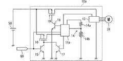
駆動装置10aは、IC11a、第1トランジスタ15、第2トランジスタ16、第3トランジスタ17、第4トランジスタ18、第5トランジスタ19を備えている。  The drivingdevice 10a includes anIC 11a, afirst transistor 15, asecond transistor 16, athird transistor 17, afourth transistor 18, and afifth transistor 19.

第1トランジスタ15は、特許請求の範囲の第1スイッチング素子に相当する。本実施形態では、一例として、第1トランジスタ15としてNPNトランジスタを採用している。第1トランジスタ15は、ベース電極にECU60が接続されており、コレクタ電極が第2トランジスタ16のゲート電極に接続されており、エミッタ電極がグランドに接続されている。第1トランジスタ15は、ECU60からの駆動指令が入力されるとオンし、ECU60からの駆動指令が停止されるとオフする。なお、ECU60からの駆動指令は、IC11aにも入力される。  Thefirst transistor 15 corresponds to the first switching element in the claims. In the present embodiment, as an example, an NPN transistor is employed as thefirst transistor 15. In thefirst transistor 15, theECU 60 is connected to the base electrode, the collector electrode is connected to the gate electrode of thesecond transistor 16, and the emitter electrode is connected to the ground. Thefirst transistor 15 is turned on when a drive command from theECU 60 is input, and turned off when the drive command from theECU 60 is stopped. The drive command from theECU 60 is also input to theIC 11a.

第2トランジスタ16は、特許請求の範囲の第2スイッチング素子に相当する。本実施形態では、一例として、第2トランジスタ16としてPチャネルMOSFETを採用している。第2トランジスタ16は、ゲート電極が第1トランジスタ15のコレクタ電極に接続されており、ドレイン電極がIC11aに接続されており、ソース電極が電源線に接続されている。第2トランジスタ16は、第1トランジスタ15又は第3トランジスタ17がオンすることでバッテリ50からIC11aへ電源供給し、第1トランジスタ15及び第3トランジスタ17がオフすることでバッテリ50からIC11aへの電源供給を停止する。  Thesecond transistor 16 corresponds to the second switching element in the claims. In the present embodiment, as an example, a P-channel MOSFET is employed as thesecond transistor 16. Thesecond transistor 16 has a gate electrode connected to the collector electrode of thefirst transistor 15, a drain electrode connected to theIC 11a, and a source electrode connected to the power supply line. Thesecond transistor 16 supplies power from thebattery 50 to theIC 11a when thefirst transistor 15 or thethird transistor 17 is turned on, and supplies power from thebattery 50 to theIC 11a when thefirst transistor 15 and thethird transistor 17 are turned off. Stop supplying.

第3トランジスタ17は、特許請求の範囲の第3スイッチング素子に相当する。本実施形態では、一例として、第3トランジスタ17としてNPNトランジスタを採用している。第3トランジスタ17は、ベース電極にIC11aが接続されており、コレクタ電極が第2トランジスタ16のゲート電極に接続されており、エミッタ電極がグランドに接続されている。第3トランジスタ17は、IC11aによってオンオフされる。  Thethird transistor 17 corresponds to a third switching element in the claims. In the present embodiment, as an example, an NPN transistor is employed as thethird transistor 17. Thethird transistor 17 has the base electrode connected to theIC 11a, the collector electrode connected to the gate electrode of thesecond transistor 16, and the emitter electrode connected to the ground. Thethird transistor 17 is turned on and off by theIC 11a.

第4トランジスタ18は、特許請求の範囲の第4スイッチング素子に相当する。本実施形態では、一例として、第4トランジスタ18としてNPNトランジスタを採用している。第4トランジスタ18は、ベース電極にIC11aが接続されており、コレクタ電極が第5トランジスタ19のゲート電極に接続されており、エミッタ電極がグランドに接続されている。第4トランジスタ18は、IC11aによってオンオフされる。  Thefourth transistor 18 corresponds to a fourth switching element in the claims. In the present embodiment, as an example, an NPN transistor is employed as thefourth transistor 18. In thefourth transistor 18, theIC 11 a is connected to the base electrode, the collector electrode is connected to the gate electrode of thefifth transistor 19, and the emitter electrode is connected to the ground. Thefourth transistor 18 is turned on and off by theIC 11a.

第5トランジスタ19は、特許請求の範囲の第5スイッチング素子に相当する。本実施形態では、一例として、第5トランジスタ19としてPチャネルMOSFETを採用している。第5トランジスタ19は、ゲート電極が第4トランジスタ18のコレクタ電極に接続されており、ドレイン電極がインバータ13に接続されており、ソース電極が電源線に接続されている。第5トランジスタ19は、第4トランジスタ18がオンすることでバッテリ50からインバータ13へ電源供給し、第4トランジスタ18がオフすることでバッテリ50からインバータ13への電源供給を停止する。  Thefifth transistor 19 corresponds to a fifth switching element in the claims. In the present embodiment, as an example, a P-channel MOSFET is employed as thefifth transistor 19. Thefifth transistor 19 has a gate electrode connected to the collector electrode of thefourth transistor 18, a drain electrode connected to theinverter 13, and a source electrode connected to the power supply line. Thefifth transistor 19 supplies power from thebattery 50 to theinverter 13 when thefourth transistor 18 is turned on, and stops supplying power from thebattery 50 to theinverter 13 when thefourth transistor 18 is turned off.

IC11aは、ECU60からの駆動指令が停止されると測定期間の間、第3トランジスタ17をオンさせてバッテリ50からの電源供給を継続させる(保持部)。そして、IC11aは、測定期間が終了すると第3トランジスタ17をオフさせて、バッテリ50からの電源供給を停止させる(保持部)。  When the driving command from theECU 60 is stopped, theIC 11a turns on thethird transistor 17 and continues the power supply from thebattery 50 during the measurement period (holding unit). Then, when the measurement period ends, theIC 11a turns off thethird transistor 17 and stops the power supply from the battery 50 (holding unit).

駆動装置10aは、ECU60から駆動指令が入力されると、第1トランジスタ15がオンすることで、第2トランジスタ16がオンして、バッテリ50からIC11aに動作電源が供給される。そして、IC11aは、動作電源が供給されると、第3トランジスタ17をオンにする。さらに、IC11aは、動作電源が供給されると、第4トランジスタ18をオンにすることで、第5トランジスタがオンして、バッテリ50からインバータ13に電源供給させる。そして、IC11aは、ECU60からの駆動指令に応じてモータ31を駆動制御する。  When a driving command is input from theECU 60, the drivingdevice 10a turns on thefirst transistor 15 to turn on thesecond transistor 16, and the operating power is supplied from thebattery 50 to theIC 11a. Then, theIC 11a turns on thethird transistor 17 when operating power is supplied. Further, when the operating power is supplied, theIC 11a turns on thefourth transistor 18 to turn on the fifth transistor, thereby supplying power from thebattery 50 to theinverter 13. Then, theIC 11a drives and controls themotor 31 in accordance with a drive command from theECU 60.

また、駆動装置10aは、ECU60からの駆動指令が停止されると、第1トランジスタ15がオフされる。そして、IC11aは、ECU60からの駆動指令が停止されてから測定期間の間、第3トランジスタ17のオンを継続する。これによって、IC11aは、測定期間の間、第2トランジスタ16のオンを継続することでき、バッテリ50から動作電源の供給が継続される。  In thedriving device 10a, when the driving command from theECU 60 is stopped, thefirst transistor 15 is turned off. TheIC 11a continues to turn on thethird transistor 17 during the measurement period after the drive command from theECU 60 is stopped. Accordingly, theIC 11a can continue to turn on thesecond transistor 16 during the measurement period, and the supply of the operating power from thebattery 50 is continued.

そして、IC11aは、測定期間の間、駆動装置10aの温度が温度閾値に達したと判定しなかった場合、第3トランジスタ17をオフにすることで、第2トランジスタ16をオフにする。これによって、IC11aは、バッテリ50から動作電源の供給が停止される。また、IC11aは、測定期間の間、駆動装置10aの温度が温度閾値に達したと判定しなかった場合、第4トランジスタ18をオフにすることで、第5トランジスタ19をオフにする。これによって、IC11aは、バッテリ50からインバータ13への電源供給を停止する。  If theIC 11a does not determine that the temperature of thedriving device 10a has reached the temperature threshold during the measurement period, theIC 11a turns off thesecond transistor 16 by turning off thethird transistor 17. As a result, theIC 11a stops supplying operating power from thebattery 50. Further, when theIC 11a does not determine that the temperature of thedriving device 10a has reached the temperature threshold during the measurement period, theIC 11a turns off thefourth transistor 18 to turn off thefifth transistor 19. Thereby, theIC 11a stops the power supply from thebattery 50 to theinverter 13.

一方、IC11aは、測定期間の間で、駆動装置10aの温度が温度閾値に達したと判定した場合、第3トランジスタ17及び第4トランジスタのオンを継続させる。そして、IC11aは、IC11と同様に、所定の冷却期間だけ、ECU60からの駆動指令にかかわらず、電動ファン30を駆動制御して電動ファン30によって駆動装置10aを冷却する。  On the other hand, when theIC 11a determines that the temperature of thedriving device 10a has reached the temperature threshold during the measurement period, theIC 11a continues to turn on thethird transistor 17 and the fourth transistor. Then, like theIC 11, theIC 11 a drives and controls theelectric fan 30 and cools thedrive device 10 a by theelectric fan 30 only during a predetermined cooling period, regardless of the drive command from theECU 60.

これによって、駆動装置10aは、駆動装置10と同様の効果を奏することができる。さらに、駆動装置10aは、ウェイク機能及びスリープ機能がないICであっても採用できる。つまり、駆動装置10aは、トランジスタをオンオフできるICであっても採用できる。  As a result, the drivingdevice 10 a can achieve the same effects as the drivingdevice 10. Furthermore, the drivingdevice 10a can be adopted even if it is an IC without a wake function and a sleep function. In other words, the drivingdevice 10a can be an IC that can turn on and off the transistor.

(第3実施形態)
図6を用いて、第3実施形態の駆動装置に関して説明する。第3実施形態の駆動装置は、ICの処理動作が駆動装置10と異なる。本実施形態では、第1実施形態と同様の点に関する説明を省略し、第1実施形態と異なる点を中心に説明する。つまり、本実施形態における第1実施形態と同様の点に関しては、第1実施形態の説明を参照して採用することができる。なお、本実施形態では、便宜的に、第1実施形態と同じ符号を用いる。
(Third embodiment)
A driving apparatus according to the third embodiment will be described with reference to FIG. The driving apparatus of the third embodiment is different from the drivingapparatus 10 in the IC processing operation. In the present embodiment, the description regarding the same points as in the first embodiment will be omitted, and the description will focus on the points different from the first embodiment. That is, the same points as in the first embodiment in this embodiment can be adopted with reference to the description of the first embodiment. In the present embodiment, the same reference numerals as those in the first embodiment are used for convenience.

IC11は、ステップS12aにおいて、温度上昇ありか否かを判定する(判定部)。つまり、IC11は、測定期間中に、駆動装置10の温度が上昇したか否かを判定する。IC11は、ステップS11で測定した少なくとも二点での温度から温度上昇しているか否かを確認する。言い換えると、IC11は、測定期間における少なくとも二点で測定された温度から温度上昇しているか否かを確認する。なお、この二点とは、異なる二つの測定タイミングである。  In step S12a, theIC 11 determines whether or not there is a temperature rise (determination unit). That is, theIC 11 determines whether or not the temperature of the drivingdevice 10 has increased during the measurement period. TheIC 11 confirms whether or not the temperature has risen from the temperature at at least two points measured in step S11. In other words, theIC 11 confirms whether or not the temperature has risen from the temperature measured at at least two points in the measurement period. These two points are two different measurement timings.

そして、IC11は、温度上昇していると判定した場合に過熱状態であると判定する。一方、IC11は、温度上昇していると判定しなかった場合に過熱状態でないと判定する。  And IC11 determines with it being in an overheated state, when it determines with the temperature rising. On the other hand, theIC 11 determines that the temperature is not overheated when it is not determined that the temperature has risen.

これによって、本実施形態の駆動装置は、駆動装置10と同様の効果を奏することができる。さらに、本実施形態の駆動装置は、温度上昇に基づいて過熱状態であるか否かを判定しているため、温度と温度閾値との比較結果に基づいて過熱状態であるか否かを判定している駆動装置10よりも、過熱状態であるか否かの判定時間を短くすることができる。よって、本実施形態の駆動装置は、駆動装置10よりも暗電流を抑制できる。  Thereby, the drive device of the present embodiment can achieve the same effects as thedrive device 10. Furthermore, since the drive device of the present embodiment determines whether or not it is in an overheated state based on the temperature rise, it determines whether or not it is in an overheated state based on the comparison result between the temperature and the temperature threshold. It is possible to shorten the determination time as to whether or not it is in an overheated state as compared with the drivingdevice 10 that is being operated. Therefore, the drive device of this embodiment can suppress dark current more than thedrive device 10.

10,10a…駆動装置、11,11a…IC、12…リレー、13…インバータ、14…温度測定回路、15…第1トランジスタ、16…第2トランジスタ、17…第3トランジスタ、18…第4トランジスタ、19…第5トランジスタ、21…筐体、22…カバー、30…電動ファン、31…モータ、32…ファン、40…機電一体装置、50…バッテリ、60…ECU、70…ラジエータ、90…エンジン、100…車両  DESCRIPTION OFSYMBOLS 10,10a ...Drive device 11, 11a ... IC, 12 ... Relay, 13 ... Inverter, 14 ... Temperature measurement circuit, 15 ... 1st transistor, 16 ... 2nd transistor, 17 ... 3rd transistor, 18 ... 4th transistor , 19 ... 5th transistor, 21 ... casing, 22 ... cover, 30 ... electric fan, 31 ... motor, 32 ... fan, 40 ... electromechanical integrated device, 50 ... battery, 60 ... ECU, 70 ... radiator, 90 ... engine , 100 ... vehicle

Claims (11)

Translated fromJapanese
外部装置からの駆動指令に基づいて、冷却対象を冷却するための電動ファンを駆動制御する駆動装置であって、
前記駆動装置の温度に応じた温度信号を出力する温度測定回路(14)と、前記駆動指令に基づいて前記電動ファンを駆動制御する処理装置(11、11a)と、を備えており、
前記処理装置は、
前記外部装置からの前記駆動指令が停止してから予め決められた測定期間の間、前記温度信号に基づいて前記駆動装置の前記温度を測定する測定部(S11)と、
前記測定部によって測定された前記温度から、前記駆動装置の冷却が必要な過熱状態であるか否かを判定する判定部(S12、S12a)と、
前記判定部によって前記過熱状態と判定された場合、前記外部装置からの前記駆動指令にかかわらず、前記電動ファンを駆動制御して前記電動ファンによって前記駆動装置を冷却する駆動部(S13)と、を備えている駆動装置。
Based on a drive command from an external device, a drive device that drives and controls an electric fan for cooling a cooling target,
A temperature measurement circuit (14) for outputting a temperature signal corresponding to the temperature of the drive device, and a processing device (11, 11a) for driving and controlling the electric fan based on the drive command,
The processor is
A measurement unit (S11) that measures the temperature of the drive device based on the temperature signal during a predetermined measurement period after the drive command from the external device stops;
A determination unit (S12, S12a) that determines whether or not the driving device is in an overheated state that requires cooling from the temperature measured by the measurement unit;
A drive unit (S13) that drives and controls the electric fan and cools the drive device by the electric fan regardless of the drive command from the external device when the determination unit determines that the overheated state; A drive device comprising:
前記処理装置は、電源(50)から電源供給されるものであって、
さらに、前記電源と前記処理装置との間の電源線に設けられ、前記処理装置によって開閉が制御されるリレー(12)と、
前記電源から電源供給され、前記電動ファンを駆動制御するために前記処理装置によって制御されるインバータ(13)と、を備えており、
前記処理装置は、前記駆動部と、前記外部装置からの前記駆動指令が停止されると前記測定期間の間は前記リレーをオンさせて電源供給を継続させ、前記測定期間が終了すると前記リレーをオフさせる保持部(S10、S16)とを含んでいる請求項1に記載の駆動装置。
The processing device is supplied with power from a power source (50),
Furthermore, a relay (12) provided on a power line between the power source and the processing device and controlled to be opened and closed by the processing device;
An inverter (13) powered by the power source and controlled by the processing device to drive and control the electric fan;
When the drive command from the drive unit and the external device is stopped, the processing device turns on the relay during the measurement period to continue power supply, and when the measurement period ends, The drive device according to claim 1, further comprising a holding portion (S10, S16) to be turned off.
前記処理装置は、前記駆動部を含んでおり、且つ、起動状態からスリープ状態へ遷移するスリープ機能を備えており、前記外部装置からの前記駆動指令が停止されると前記測定期間の間は前記起動状態を継続させ、前記測定期間が終了すると前記スリープ状態へ遷移する保持部を含んでいる請求項2に記載の駆動装置。  The processing device includes the drive unit, and has a sleep function for transitioning from a startup state to a sleep state, and when the drive command from the external device is stopped, The drive device according to claim 2, further comprising a holding unit that continues the activated state and transitions to the sleep state when the measurement period ends. 前記処理装置は、電源(50)から電源供給されるものであって、
さらに、前記電源から電源供給され、前記電動ファンを駆動制御するために、前記処理装置によって制御されるインバータ(13)と
前記駆動指令が入力されるとオンし、前記駆動指令が停止されるとオフする第1スイッチング素子(15)と、
前記処理装置によってオンオフされる第3スイッチング素子(17)と、
前記第1スイッチング素子又は前記第3スイッチング素子がオンすることで前記電源から前記処理装置へ電源供給し、前記第1スイッチング素子及び前記第3スイッチング素子がオフすることで前記電源から前記処理装置への電源供給を停止する第2スイッチング素子(16)と、
前記処理装置によってオンオフされる第4スイッチング素子(18)と、
前記第4スイッチング素子がオンすることで前記電源から前記インバータへ電源供給し、前記第4スイッチング素子がオフすることで前記電源から前記インバータへの電源供給を停止する第5スイッチング素子(19)と、を備えており、
前記処理装置は、前記駆動部と、前記外部装置からの前記駆動指令が停止されると前記測定期間の間は前記第3スイッチング素子をオンさせて電源供給を継続させ、前記測定期間が終了すると前記第3スイッチング素子をオフさせる保持部とを含んでいる請求項1に記載の駆動装置。
The processing device is supplied with power from a power source (50),
Further, in order to control the drive of the electric fan supplied with power from the power source, the inverter (13) controlled by the processing device and the drive command are turned on and the drive command is stopped. A first switching element (15) to be turned off;
A third switching element (17) which is turned on and off by the processing device;
When the first switching element or the third switching element is turned on, power is supplied from the power source to the processing apparatus, and when the first switching element and the third switching element are turned off, the power source is supplied to the processing apparatus. A second switching element (16) for stopping the power supply of
A fourth switching element (18) turned on and off by the processing device;
A fifth switching element (19) for supplying power from the power source to the inverter by turning on the fourth switching element, and stopping power supply from the power source to the inverter by turning off the fourth switching element; , And
When the drive command from the drive unit and the external device is stopped, the processing device turns on the third switching element during the measurement period to continue power supply, and the measurement period ends. The drive device according to claim 1, further comprising a holding unit that turns off the third switching element.
前記温度測定回路は、少なくとも二つ設けられており、
前記測定部は、少なくとも二つの前記温度測定回路からの信号に基づいて、前記駆動装置の前記温度を測定する請求項1乃至4のいずれか一項に記載の駆動装置。
At least two temperature measuring circuits are provided,
5. The drive device according to claim 1, wherein the measurement unit measures the temperature of the drive device based on signals from at least two of the temperature measurement circuits.
前記判定部は、前記測定部によって前記測定期間で測定された前記温度が、前記過熱状態であるか否かを判定する温度閾値に達した場合に前記過熱状態であると判定する請求項1乃至5のいずれか一項に記載の駆動装置。  The said determination part determines with the said overheating state, when the said temperature measured by the said measurement part reaches the temperature threshold value which determines whether it is the said overheating state. The drive device according to any one of 5. 前記温度閾値は、前記駆動装置内の熱耐量が最も小さい部位よりも低い温度である請求項6に記載の駆動装置。  The drive device according to claim 6, wherein the temperature threshold is a temperature lower than a portion having the smallest heat resistance in the drive device. 前記判定部は、前記測定部によって前記測定期間における少なくとも二点で測定された前記温度から温度上昇しているか否かを確認し、温度上昇している場合に前記過熱状態であると判定する請求項1乃至5のいずれか一項に記載の駆動装置。  The determination unit confirms whether or not the temperature has risen from the temperature measured at at least two points in the measurement period by the measurement unit, and determines that the overheated state is present when the temperature has increased. Item 6. The driving device according to any one of Items 1 to 5. 前記測定期間は、前記駆動装置の熱時定数の2.3倍である請求項1乃至8のいずれか一項に記載の駆動装置。  The driving apparatus according to claim 1, wherein the measurement period is 2.3 times a thermal time constant of the driving apparatus. 前記駆動部は、電源としてバッテリから電源供給されるものであり、現在のバッテリ容量が所定値以下の場合、前記判定部によって前記過熱状態と判定された場合であっても、前記電動ファンの駆動制御を禁止する請求項1乃至9のいずれか一項に記載の駆動装置。  The drive unit is powered by a battery as a power source. When the current battery capacity is equal to or less than a predetermined value, the drive of the electric fan is performed even when the determination unit determines that the overheated state is present. The drive device according to any one of claims 1 to 9, wherein control is prohibited. 前記駆動部は、前記電動ファンによって前記駆動装置を冷却する場合、前記電動ファンを最低回転数で回すように駆動制御する請求項1乃至10のいずれか一項に記載の駆動装置。  The drive device according to any one of claims 1 to 10, wherein the drive unit performs drive control so that the electric fan is rotated at a minimum number of rotations when the drive device is cooled by the electric fan.
JP2017067933A2017-03-302017-03-30Driving devicePendingJP2018170906A (en)

Priority Applications (1)

Application NumberPriority DateFiling DateTitle
JP2017067933AJP2018170906A (en)2017-03-302017-03-30Driving device

Applications Claiming Priority (1)

Application NumberPriority DateFiling DateTitle
JP2017067933AJP2018170906A (en)2017-03-302017-03-30Driving device

Publications (1)

Publication NumberPublication Date
JP2018170906Atrue JP2018170906A (en)2018-11-01

Family

ID=64018040

Family Applications (1)

Application NumberTitlePriority DateFiling Date
JP2017067933APendingJP2018170906A (en)2017-03-302017-03-30Driving device

Country Status (1)

CountryLink
JP (1)JP2018170906A (en)

Cited By (1)

* Cited by examiner, † Cited by third party
Publication numberPriority datePublication dateAssigneeTitle
JP2024071457A (en)*2020-08-182024-05-24株式会社デンソー Load Drive System

Citations (9)

* Cited by examiner, † Cited by third party
Publication numberPriority datePublication dateAssigneeTitle
JPS58140415A (en)*1982-02-131983-08-20Honda Motor Co Ltd Automotive cooling system control device
JPH08186926A (en)*1994-12-281996-07-16Jatco CorpController for automobile
JPH09145215A (en)*1995-11-241997-06-06Matsushita Refrig Co LtdCooling method of inverter device for refrigerator
JPH10210790A (en)*1997-01-271998-08-07Toyota Motor Corp Overheat protection device for power converter, inverter control device and inverter cooling device for electric vehicle having the function
JP2001169401A (en)*1999-12-022001-06-22Honda Motor Co Ltd Electric vehicle control device
JP3109571U (en)*2004-12-272005-05-19青麟 周 Operation control device for heat dissipation fan
JP2010068623A (en)*2008-09-102010-03-25Toyota Motor CorpPower system and vehicle equipped with it
JP2010203246A (en)*2009-02-272010-09-16Hitachi Koki Co LtdEngine working machine
JP2014014243A (en)*2012-07-042014-01-23Asmo Co LtdBrushless motor

Patent Citations (9)

* Cited by examiner, † Cited by third party
Publication numberPriority datePublication dateAssigneeTitle
JPS58140415A (en)*1982-02-131983-08-20Honda Motor Co Ltd Automotive cooling system control device
JPH08186926A (en)*1994-12-281996-07-16Jatco CorpController for automobile
JPH09145215A (en)*1995-11-241997-06-06Matsushita Refrig Co LtdCooling method of inverter device for refrigerator
JPH10210790A (en)*1997-01-271998-08-07Toyota Motor Corp Overheat protection device for power converter, inverter control device and inverter cooling device for electric vehicle having the function
JP2001169401A (en)*1999-12-022001-06-22Honda Motor Co Ltd Electric vehicle control device
JP3109571U (en)*2004-12-272005-05-19青麟 周 Operation control device for heat dissipation fan
JP2010068623A (en)*2008-09-102010-03-25Toyota Motor CorpPower system and vehicle equipped with it
JP2010203246A (en)*2009-02-272010-09-16Hitachi Koki Co LtdEngine working machine
JP2014014243A (en)*2012-07-042014-01-23Asmo Co LtdBrushless motor

Cited By (2)

* Cited by examiner, † Cited by third party
Publication numberPriority datePublication dateAssigneeTitle
JP2024071457A (en)*2020-08-182024-05-24株式会社デンソー Load Drive System
JP7715226B2 (en)2020-08-182025-07-30株式会社デンソー Load Drive System

Similar Documents

PublicationPublication DateTitle
JP4290461B2 (en) Cooling system and cooling control method for electric device
CN103328248B (en)The cooling system of vehicle-mounted rotating machine power inverter
JP5408136B2 (en) Inverter device, inverter control system, motor control system, and control method for inverter device
CN103660993B (en)The actuating device of electrical motor
CN115118200A (en) Control device and control method
CN107208905B (en) Air-conditioning control system and method for controlling air-conditioning
JPH0450496B2 (en)
JP2010173445A (en)Cooling system for hybrid vehicle
KR20130128881A (en)Cooling system for electric vehicle
JP2018170906A (en)Driving device
JP4200885B2 (en) Motor drive device for electric compressor
CN103250346B (en) rotating electrical machine
JP2019188945A (en)On-vehicle cooling device
JP4861367B2 (en) Electric fan control device
JP6021461B2 (en) Outdoor unit for air conditioner and control method thereof
JP6005451B2 (en) Voltage control circuit
WO2006025689A1 (en)Cooling device for computer using thermoelectric element, air-cooling kit and duct
US10720371B2 (en)Extended temperature operation for electronic systems using induction heating
JP2007041739A (en)Fan drive control method and device
JPH102222A (en)Electric motor fan control device used in cooling system for automobile
JP2003029880A (en)Cooling system for information processor
JP4374376B2 (en) Controller-integrated rotating electrical machine
JP2019075908A (en)Controller
JP2010225095A (en)Information processor
JPH042859B2 (en)

Legal Events

DateCodeTitleDescription
A621Written request for application examination

Free format text:JAPANESE INTERMEDIATE CODE: A621

Effective date:20190716

A977Report on retrieval

Free format text:JAPANESE INTERMEDIATE CODE: A971007

Effective date:20200619

A131Notification of reasons for refusal

Free format text:JAPANESE INTERMEDIATE CODE: A131

Effective date:20200707

A521Request for written amendment filed

Free format text:JAPANESE INTERMEDIATE CODE: A523

Effective date:20200821

A131Notification of reasons for refusal

Free format text:JAPANESE INTERMEDIATE CODE: A131

Effective date:20201124

A521Request for written amendment filed

Free format text:JAPANESE INTERMEDIATE CODE: A523

Effective date:20210121

A02Decision of refusal

Free format text:JAPANESE INTERMEDIATE CODE: A02

Effective date:20210330


[8]ページ先頭

©2009-2025 Movatter.jp