JP2018166318A - Maritime communication network construction method and communication terminal - Google Patents
Maritime communication network construction method and communication terminalDownload PDFInfo
- Publication number
- JP2018166318A JP2018166318AJP2017064061AJP2017064061AJP2018166318AJP 2018166318 AJP2018166318 AJP 2018166318AJP 2017064061 AJP2017064061 AJP 2017064061AJP 2017064061 AJP2017064061 AJP 2017064061AJP 2018166318 AJP2018166318 AJP 2018166318A
- Authority
- JP
- Japan
- Prior art keywords
- ship
- communication
- communication terminal
- base station
- connection request
- Prior art date
- Legal status (The legal status is an assumption and is not a legal conclusion. Google has not performed a legal analysis and makes no representation as to the accuracy of the status listed.)
- Pending
Links
Images


Classifications
- H—ELECTRICITY
- H04—ELECTRIC COMMUNICATION TECHNIQUE
- H04W—WIRELESS COMMUNICATION NETWORKS
- H04W76/00—Connection management
- H04W76/10—Connection setup
- H04W76/14—Direct-mode setup
- G—PHYSICS
- G01—MEASURING; TESTING
- G01S—RADIO DIRECTION-FINDING; RADIO NAVIGATION; DETERMINING DISTANCE OR VELOCITY BY USE OF RADIO WAVES; LOCATING OR PRESENCE-DETECTING BY USE OF THE REFLECTION OR RERADIATION OF RADIO WAVES; ANALOGOUS ARRANGEMENTS USING OTHER WAVES
- G01S5/00—Position-fixing by co-ordinating two or more direction or position line determinations; Position-fixing by co-ordinating two or more distance determinations
- G01S5/02—Position-fixing by co-ordinating two or more direction or position line determinations; Position-fixing by co-ordinating two or more distance determinations using radio waves
- G01S5/0205—Details
- G01S5/0236—Assistance data, e.g. base station almanac
- G—PHYSICS
- G01—MEASURING; TESTING
- G01S—RADIO DIRECTION-FINDING; RADIO NAVIGATION; DETERMINING DISTANCE OR VELOCITY BY USE OF RADIO WAVES; LOCATING OR PRESENCE-DETECTING BY USE OF THE REFLECTION OR RERADIATION OF RADIO WAVES; ANALOGOUS ARRANGEMENTS USING OTHER WAVES
- G01S5/00—Position-fixing by co-ordinating two or more direction or position line determinations; Position-fixing by co-ordinating two or more distance determinations
- G01S5/02—Position-fixing by co-ordinating two or more direction or position line determinations; Position-fixing by co-ordinating two or more distance determinations using radio waves
- G01S5/04—Position of source determined by a plurality of spaced direction-finders
- G—PHYSICS
- G01—MEASURING; TESTING
- G01S—RADIO DIRECTION-FINDING; RADIO NAVIGATION; DETERMINING DISTANCE OR VELOCITY BY USE OF RADIO WAVES; LOCATING OR PRESENCE-DETECTING BY USE OF THE REFLECTION OR RERADIATION OF RADIO WAVES; ANALOGOUS ARRANGEMENTS USING OTHER WAVES
- G01S5/00—Position-fixing by co-ordinating two or more direction or position line determinations; Position-fixing by co-ordinating two or more distance determinations
- G01S5/02—Position-fixing by co-ordinating two or more direction or position line determinations; Position-fixing by co-ordinating two or more distance determinations using radio waves
- G01S5/10—Position of receiver fixed by co-ordinating a plurality of position lines defined by path-difference measurements, e.g. omega or decca systems
- H—ELECTRICITY
- H04—ELECTRIC COMMUNICATION TECHNIQUE
- H04W—WIRELESS COMMUNICATION NETWORKS
- H04W76/00—Connection management
- H04W76/10—Connection setup
- G—PHYSICS
- G01—MEASURING; TESTING
- G01S—RADIO DIRECTION-FINDING; RADIO NAVIGATION; DETERMINING DISTANCE OR VELOCITY BY USE OF RADIO WAVES; LOCATING OR PRESENCE-DETECTING BY USE OF THE REFLECTION OR RERADIATION OF RADIO WAVES; ANALOGOUS ARRANGEMENTS USING OTHER WAVES
- G01S19/00—Satellite radio beacon positioning systems; Determining position, velocity or attitude using signals transmitted by such systems
- G01S19/38—Determining a navigation solution using signals transmitted by a satellite radio beacon positioning system
- G01S19/39—Determining a navigation solution using signals transmitted by a satellite radio beacon positioning system the satellite radio beacon positioning system transmitting time-stamped messages, e.g. GPS [Global Positioning System], GLONASS [Global Orbiting Navigation Satellite System] or GALILEO
- G01S19/42—Determining position
- G01S19/45—Determining position by combining measurements of signals from the satellite radio beacon positioning system with a supplementary measurement
- G01S19/46—Determining position by combining measurements of signals from the satellite radio beacon positioning system with a supplementary measurement the supplementary measurement being of a radio-wave signal type
- H—ELECTRICITY
- H04—ELECTRIC COMMUNICATION TECHNIQUE
- H04W—WIRELESS COMMUNICATION NETWORKS
- H04W64/00—Locating users or terminals or network equipment for network management purposes, e.g. mobility management
- H—ELECTRICITY
- H04—ELECTRIC COMMUNICATION TECHNIQUE
- H04W—WIRELESS COMMUNICATION NETWORKS
- H04W84/00—Network topologies
- H04W84/18—Self-organising networks, e.g. ad-hoc networks or sensor networks
- H—ELECTRICITY
- H04—ELECTRIC COMMUNICATION TECHNIQUE
- H04W—WIRELESS COMMUNICATION NETWORKS
- H04W88/00—Devices specially adapted for wireless communication networks, e.g. terminals, base stations or access point devices
- H04W88/02—Terminal devices
- H04W88/04—Terminal devices adapted for relaying to or from another terminal or user
Landscapes
- Engineering & Computer Science (AREA)
- Physics & Mathematics (AREA)
- General Physics & Mathematics (AREA)
- Radar, Positioning & Navigation (AREA)
- Remote Sensing (AREA)
- Computer Networks & Wireless Communication (AREA)
- Signal Processing (AREA)
- Mobile Radio Communication Systems (AREA)
Abstract
Translated fromJapaneseDescription
Translated fromJapaneseこの発明は、海上における通信ネットワーク構築方法および通信端末に関する。 The present invention relates to a communication network construction method and a communication terminal at sea.
船舶、特にモーターボートなどの小型船舶が海上を航行する際に、クラウドなどのサーバにアクセスして、自船の航行状況の情報を送信(アップロード)したり、航行に必要な情報を取得(ダウンロード)したりすることが望まれる。その場合、船舶に搭載した無線LAN等の無線データ通信用の通信端末から、陸上の基地局(アクセスポイント)を経由してサーバにアクセスすることになる。 When a ship, especially a small boat such as a motor boat, sails on the sea, it accesses a server such as a cloud to send (upload) information on the ship's navigation status, and acquire (download) information necessary for navigation. It is desirable to do. In that case, a server is accessed via a land base station (access point) from a communication terminal for wireless data communication such as a wireless LAN mounted on a ship.
しかし、海上に基地局を設置するのは困難であるため、海上を航行する船舶は通信可能圏外になってしまうことが多い。そのため、電波強度の強い無線通信端末を使用するか、陸地に近づいて、基地局との通信可能圏内に入ってからサーバにアクセスするなどの手法をとっていたが、コスト高になるか、データのリアルタイム性に欠けるなどの問題があった。大型船では衛星電話を使用することが多いが、さらにコスト高になるため、小型船舶では使用できない。 However, since it is difficult to install a base station on the sea, a ship that sails on the sea often goes out of communication range. For this reason, methods such as using a wireless communication terminal with strong radio field strength, or approaching the land and accessing the server after entering the communicable area with the base station have been adopted. There were problems such as lack of real-time performance. Large ships often use satellite telephones, but they are more expensive and cannot be used on smaller ships.
ところで、複数の通信端末の間でグループ通信を行う通信方法としては、特許文献1に記載の技術がある。その技術は、自由に移動する多数の通信端末のうち、電波の到達範囲内にある隣り合った通信端末間で通信路を形成することを順次行なって、各通信端末が隣接する通信端末を中継点としてグループ内の他の任意の通信端末と通信可能なネットワークを形成するものである。 Incidentally, as a communication method for performing group communication among a plurality of communication terminals, there is a technique described in
特許文献1に記載の技術は上記のように構成することで、基地局を用いずに、グループ内の各通信端末が他の通信端末とオンデマンド型の通信を行うことを可能にしている。しかしながら、これは街中などの陸上で一時的に集合する通信端末間でデータの送受信を行うための方法であり、海上を航行する複数の各船舶と陸上の基地局を経由したクラウド等のサーバとの通信に適用することはできない。 The technology described in
従って、この発明の目的は上記した課題を解決し、海上を航行する複数艘の船からなる船舶群において、地上の基地局との通信可能圏外にある船舶でも基地局と通信可能にするための、海上における通信ネットワーク構築方法、およびそれに使用する通信端末を提供することにある。なお、この明細書中でいう「海上」には「湖上」も含む。 Accordingly, an object of the present invention is to solve the above-described problems, and to enable a ship group consisting of a plurality of ships sailing on the sea to communicate with the base station even in a ship outside the communicable area with the ground base station. Another object of the present invention is to provide a marine communication network construction method and a communication terminal used therefor. In this specification, “on the sea” includes “on the lake”.
上記した課題を解決するため、この発明にあっては、海上を航行する自船と複数艘の他船からなる船舶群の各船舶にそれぞれ搭載された無線データ通信用の通信端末によって、前記自船から陸上の基地局に通信するための通信ネットワーク構築方法であって、前記自船の前記通信端末が、前記他船のうちの少なくとも前記基地局と通信可能な圏内に存在する船舶を含む船舶の前記通信端末との間で通信ネットワークを構築して相互に通信可能な通信路を確立すると共に、前記自船の通信端末は前記確立された通信路を介して前記基地局と通信する如く構成した。 In order to solve the above-described problems, in the present invention, the communication terminal for wireless data communication mounted on each ship of the ship group consisting of the own ship navigating at sea and other ships of a plurality of ships is used to A communication network construction method for communicating from a ship to a land base station, wherein the ship includes a ship in which the communication terminal of the ship is located within a communication range of at least the base station among the other ships. A communication network is established with the communication terminal to establish a communication path capable of mutual communication, and the communication terminal of the ship is configured to communicate with the base station via the established communication path. did.
以下、添付図面に即してこの発明の実施形態に係る海上における通信ネットワーク構築方法および通信端末を実施するための形態について説明する。 DESCRIPTION OF EXEMPLARY EMBODIMENTS A mode for carrying out a communication network construction method and a communication terminal according to an embodiment of the invention will be described below with reference to the accompanying drawings.
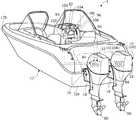
図1はこの発明の実施形態に係る海上における通信ネットワーク構築方法を実施する船舶である小型船舶の例を斜め後方から見た外観斜視図、図2は図1の船舶に搭載される船外機の(部分断面)拡大側面図、図3はその船外機の要部説明図である。 FIG. 1 is an external perspective view of an example of a small ship that is a ship that implements a communication network construction method at sea according to an embodiment of the present invention, and FIG. 2 is an outboard motor mounted on the ship of FIG. (Partial cross section) enlarged side view, FIG. 3 is an explanatory view of the main part of the outboard motor.
図1において符号1はいわゆるモーターボートと呼ばれる小型船舶を示す。尚、この明細書で「小型船舶」は、具体的には総トン数20トン未満の船舶を意味する。 In FIG. 1,
図1に示す小型船舶(以下「船舶」と略称)1は2基の船外機10を船体12(あるいは船舶1)の船尾12aに搭載してなる、いわゆる2基(偶数基)掛けの船舶である。図1では、進行方向左側(左舷側)の船外機を「第1船外機10A」として添え字Aを付し、進行方向右側(右舷側)の船外機を「第2船外機10B」として添え字Bを付して括弧内に示す。しかし、第1船外機10Aと第2船外機10Bは同一構造の船外機であるため、以下、添え字A,Bの付記を省略し、いずれも船外機10として説明する。 A small vessel (hereinafter abbreviated as “ship”) 1 shown in FIG. 1 has two
船外機10は、図1と図2に示すように、スイベルケース14とチルティングシャフト16によってスターンブラケット18を介して船体12の船尾12aに取り付けられる。尚、船体12(あるいは船舶1)の船首を符号12bで示す。 As shown in FIGS. 1 and 2, the
船外機10はマウントフレーム20とスイベルシャフト22を備え、スイベルシャフト22がスイベルケース14の内部に鉛直軸回りに回転自在に収容されることで、船外機10は船体12に対して鉛直軸回りに回転自在に構成される。マウントフレーム20は、その上端と下端が船外機10の本体を構成するフレーム(図示せず)に固定される。 The
スイベルケース14の付近には、スイベルシャフト22を駆動する操舵用電動モータ24と、船外機10の船体12に対するチルト角およびトリム角を調節するパワーチルトトリムユニット26が配置される。操舵用電動モータ24の出力軸は減速ギヤ機構28を介してマウントフレーム20の上端に接続される。即ち、操舵用電動モータ24の回転出力が減速ギヤ機構28を介してマウントフレーム20に伝達され、よって船外機10はスイベルシャフト22を操舵軸として左右に鉛直軸回りに操舵自在に構成される。 In the vicinity of the
パワーチルトトリムユニット26は、チルト角調整用の油圧シリンダ26aとトリム角(船体12の幅方向の水平軸であるピッチ軸(x軸)回りの船外機10の回転角)調整用の油圧シリンダ(トリムアクチュエータ)26bを一体的に備えている。そして、油圧シリンダ26a,26bに作動油を供給(あるいはそれから排出)して伸縮させることによって、スイベルケース14がチルティングシャフト16を回転軸として鉛直軸に直交する水平軸(ピッチ軸)回りに回転される。それによって、船外機10はチルトアップ・ダウンあるいはトリムアップ・ダウン自在に構成される。 The power
船外機10の上部には、エンジン(内燃機関)30が内蔵(搭載)される。エンジン30は火花点火式の水冷ガソリンエンジンからなる。エンジン30は水面上に位置し、エンジンカバー32によって覆われる。 An engine (internal combustion engine) 30 is built in (mounted on) the
エンジン30の吸気管34には、スロットルボディ36が接続される。スロットルボディ36はその内部にスロットルバルブ38を備えると共に、スロットルバルブ38を開閉するスロットル用電動モータ(スロットルアクチュエータ)40が一体的に取り付けられる。 A
スロットル用電動モータ40の出力軸はスロットルボディ36に隣接して配置された減速ギヤ機構(図示せず)を介してスロットルバルブ38に接続され、スロットル用電動モータ40を動作させることでスロットルバルブ38が開閉され、エンジン30の吸気量が調量されてエンジン回転数が調節される。 The output shaft of the throttle
船外機10は、鉛直軸と平行に配置されて回転自在に支持されるドライブシャフト(バーチカルシャフト)42と、エンジン30とドライブシャフト42の間に介挿されるトルクコンバータ44と、ドライブシャフト42に取り付けられて作動油を吐出する油圧ポンプ46と、作動油を貯留するリザーバ50を備える。 The
油圧ポンプ46はエンジン30で駆動され、リザーバ50から作動油を汲み上げ、エンジン30の潤滑部と、パワーチルトトリムユニット26の油圧シリンダ26a,26bと、トルクコンバータ44のロックアップ機構44aなどに作動油を供給する。 The
船外機10内には、エンジン30によって回転されるドライブシャフト42の下端部に、ベベルギヤ機構を含むシフト機構54を介して回転されるプロペラシャフト56が、船体12の進行方向に対して略平行になるように、水平軸回りに回転自在に支持されている。ドライブシャフト42の上端には、エンジン30のクランクシャフト52がトルクコンバータ44を介して接続される。プロペラシャフト56は、パワーチルトトリムユニット26の初期状態において、その軸線56aが船体12の進行方向に対して略平行となるように配置される。そのプロペラシャフト56の一端に、プロペラ60が取り付けられている。 In the
シフト機構54は、ドライブシャフト42に接続されて回転させられる前進ベベルギヤ54aと後進ベベルギヤ54b、プロペラシャフト56を前進ベベルギヤ54aと後進ベベルギヤ54bのいずれかに係合自在とするクラッチ54cなどからなる。 The
エンジンカバー32の内部にはシフト機構54を駆動するシフト用電動モータ62が配置され、その出力軸は、減速ギヤ機構(図示せず)を介してシフト機構54のシフトロッド54dの上端に接続自在とされる。シフト用電動モータ62を駆動することにより、シフトロッド54dとシフトスライダ54eが適宜に変位され、それによってクラッチ54cを動作させて、シフトポジションがフォワード、リバースおよびニュートラルの間で切り替えられる。 A shift
シフトポジションがフォワードあるいはリバースのとき、ドライブシャフト42の回転はシフト機構54を介してプロペラシャフト56に伝達され、よってプロペラ60は回転させられ、船体12を前進あるいは後進させる方向の推力を生じる。シフトポジションがフォワードの時の船体12の進行方向は、図2に矢示Pで示す方向である。尚、船外機10はエンジン30に取り付けられたバッテリなどの電源部(図示せず)を備え、各電動モータ24,40,62の通電回路(図示せず)に動作電源が供給される。 When the shift position is forward or reverse, the rotation of the
ここで、センサ関係について図3を参照して説明すると、図2のスロットルバルブ38の付近にはスロットル開度センサ66が配置され、スロットルバルブ38の開度(スロットル開度)を示す出力を生じる。図2のシフトロッド54dの付近にはシフト位置センサ68が配置されてシフトポジション(ニュートラル、フォワードおよびリバース)に応じた信号を出力すると共に、ニュートラルスイッチ70も配置されて、シフトポジションがニュートラルであるときにオン信号を、フォワードあるいはリバースであるときにオフ信号を出力する。 Here, the sensor relationship will be described with reference to FIG. 3. A
図2のエンジン30のクランクシャフト52の付近にはクランク角センサ74が取り付けられて、所定のクランク角度ごとにエンジン回転数に応じたパルス信号を出力する。また、ドライブシャフト42の付近にはドライブシャフト回転数センサ76が取り付けられ、ドライブシャフト42の回転数に応じた信号を出力する。スイベルケース14の付近にはトリム角センサ(回転角センサ)78が配置され、船外機10のトリム角に応じた出力を生じる。 A
また、船外機10の適宜位置にはGPS(Global Positioning System)受信機80が配置されて、衛星から送信される船舶1の位置を示すGPS信号を受信すると共に、方位センサ82が配置されて船舶1の方位を示す出力を生じる。 In addition, a GPS (Global Positioning System)
上記した各センサやスイッチの出力は、船外機10に搭載された電子制御ユニット(Electronic Control Unit:以下「ECU」という)84に入力される。ECU84はCPUやROM、RAMなどを備えたマイクロ・コンピュータからなり、船外機10のエンジンカバー32の内部に配置(搭載)される。ECU84はGPS受信機80の受信信号と方位センサ82の出力に基づき、船舶1の現在位置と航行速度と方位とを検出する。 The outputs of the sensors and switches described above are input to an electronic control unit (hereinafter referred to as “ECU”) 84 mounted on the
図1に示す如く、船体12の操縦席90の付近には、操船者によって回転操作自在なステアリングホイール92が配置される。ステアリングホイール92のシャフト(図示せず)には操舵角センサ94が取り付けられ、操船者によって入力されたステアリングホイール92の操舵角に応じた信号を出力する。 As shown in FIG. 1, a
操縦席90のダッシュボード96には、操船者による操作自在に配置されるシフト・スロットルレバー98が設けられる。シフト・スロットルレバー98は、初期位置から前後方向に揺動操作自在とされ、操船者からのシフトチェンジ指示とエンジン回転数の調節指示を入力する。シフト・スロットルレバー98の付近にはレバー位置センサ100が取り付けられ、操船者によって操作されたシフト・スロットルレバー98の位置に応じた信号を出力する。 The
操縦席90付近には操船者に手動操作自在に設けられると共に、船外機10のチルト角およびトリム角の調整指示を入力するパワーチルトトリムスイッチ102が配置され、操船者によって入力された船外機10のチルトアップ・ダウンおよびトリムアップ・ダウンの指示に応じた信号を出力する。 A power tilt
さらに操縦席90付近のダッシュボード96には、航行速度などを表示する計器類とコンパスなどの航海用機器104が配置されると共に、ディスプレイ106が配置される。ディスプレイ106は、船舶1の左右(幅)方向をx軸(ピッチ軸)、進行方向をy軸(ロール軸)とするx,y座標平面を示すスクリーンを備えると共に、そこにGPS受信機80と方位センサ82から得られた船舶1の位置と方位などが示される。 Further, on the
これら操舵角センサ94、レバー位置センサ100およびパワーチルトトリムスイッチ102の出力もECU84に入力される。ECU84は、上記したセンサやスイッチの出力に基づいて各電動モータの動作を制御し、パワーチルトトリムユニット26を作動させてトリム角を調整する。 The outputs of the
上記した船外機10の説明は第1船外機10Aについてのものであるが、第2船外機10Bについても妥当する。第1船外機10AのECU84と第2船外機10BのECU84は有線(図1に一点鎖線で示す)で接続され、相互に通信自在に構成される。 The above description of the
さらに、操縦席90の付近のダッシュボード96には、無線データ(デジタル信号)通信用の通信端末120が搭載される。この通信端末120は、この発明により海上における通信ネットワークを構築すると共に、その通信ネットワークによって地上の基地局と通信し、クラウド等のサーバにアクセスするための機能を有する。この通信端末120と船外機10のECU84とは有線で接続され、相互に通信可能である。 Furthermore, a
この通信端末120は、比較的近距離(例えば、海上で数100m〜数km程度)の無線データ通信を行うための通信端末であり、IEEE802.11シリーズの規格による無線LAN(Wi−Fi,Zigbee等)や、IEEE802.15.1規格のブルートゥース(登録商標)(Bluetooth(登録商標))あるいは拡張規格のBluetooth(登録商標)5等でデータ通信を行う通信端末である。したがって、衛星電話装置やアマチュア無線機のような短波の遠距離アナログ通信装置、および電波強度の強い無線端末等は含まない。通信可能距離は最大で3km程度を想定する。 The
図4はこの発明の実施形態に係る海上における通信ネットワーク構築方法を説明するための概念図である。 FIG. 4 is a conceptual diagram for explaining a marine communication network construction method according to an embodiment of the present invention.
図4に示す実施形態は、ボートタクシーやレンタルボートなどを想定しており、海上2の所定海域2a内で複数艘の船舶1A〜1Gが自由に航行する。その各船舶1A〜1Gは図1〜図3によって説明した船舶1と同様な小型船舶であるが、船外機が2基掛けの船舶に限るものではなく、1基掛けや3基掛けなどでもよい。その他の構成も前述のものに限らない。 The embodiment shown in FIG. 4 assumes a boat taxi, a rental boat, or the like, and a plurality of
各船舶1A〜1Gには、それぞれ前述した無線データ通信用の双方向通信機能を持つ通信端末120を搭載している。一方、陸上4にはインターネットによるクラウド300上のサーバ310にアクセスするための基地局200が設置されている。しかし、通信端末120がその基地局200と通信可能な圏内200aは、所定海域2aの一部分しかカバーできない。 Each
そこで、この発明を適用し、海上2を航行する自船と複数艘の他船からなる船舶群の各船舶1A〜1Gにそれぞれ搭載された無線データ通信用の通信端末120(以下の説明では符号「120」の記載を省略する)によって、自船から陸上4の基地局200と通信する通信ネットワークを構築する。 Therefore, the present invention is applied to a wireless data communication communication terminal 120 (reference numeral in the following description) mounted on each
図4の例では、船舶群を構成する船舶1A〜1Gのうち、船舶1Gのみが基地局200と通信可能な圏内200aに在り、基地局200から最も遠くに在る船舶1Aが自船として、基地局200と通信するための通信ネットワークを構築するものとする。 In the example of FIG. 4, among the
そこで、船舶1Aの通信端末が基地局200との接続を要求する接続要求コマンドをブロードキャストで送信する。図4ではその接続要求コマンドを破線矢印と丸付き数字「1」で示す。船舶1A〜1Gの通信端末は、それぞれを識別するための固有のIDを有しており、接続要求コマンドには発信元の通信端末のIDを付加する。接続要求コマンドをブロードキャストで送信せずに、自船より陸上4に近い側にある近隣の船舶に対して(宛先を指定して)順次送信するようにしてもよい。 Therefore, the communication terminal of the
そして、その接続要求コマンドを受信できた他船(図4では船舶1B,1C,1D)の各通信端末(受信元)が、接続要求コマンドの送信元である船舶1Aの通信端末に接続要求OKのレスポンスを送信する。そのレスポンスにも受信元の通信端末のIDを付加する。図4ではその接続要求OKのレスポンスを破線矢印と丸付き数字「2」で示す。 Then, the communication terminals (reception sources) of the other ships (
そのレスポンスを船舶1Aの通信端末が受信することによって、船舶1Aの通信端末と、船舶1B,1C,1Dの各通信端末との間に相互に通信可能な通信路を確立する。図4ではそれを実線の両方向矢印と丸付き数字「3」で示す。 When the communication terminal of the
それと同時に、基地局200との接続を要求する接続要求コマンドを受信した船舶1B,1C,1Dの通信端末(受信元)が今度は発信元になって、基地局200との接続を要求する接続要求コマンドを上記と同様に送信する。そして、船舶1Bの通信端末からの接続要求コマンドを受信できた船舶のうち、通信路を確立済である船舶1A以外の船舶1C,1D,1E,1Fの各通信端末が、発信元である船舶1Bの通信端末に接続要求OKのレスポンスを送信する。 At the same time, the communication terminal (reception source) of the
その各レスポンスを船舶1Bの通信端末が受信すると、その船舶1Bの通信端末と、船舶1C,1D,1E,1Fの各通信端末との間に相互に通信可能な通信路を確立する。同様にして、船舶1Cの通信端末と船舶1Fの通信端末との間、および船舶1Dの通信端末と船舶1Eの通信端末との間にも相互に通信可能な通信路を確立する。それらの通信路の確立を、図4では実線の両方向矢印と丸付き数字「4」で示す。 When the communication terminal of the
さらに、基地局200との接続を要求する接続要求コマンドを受信した船舶1Fの通信端末が今度は発信元になって、接続要求コマンドを上記と同様に送信する。それを船舶1Gの通信端末が受信して、発信元の船舶1Fの通信端末に接続要求OKのレスポンスを送信する。それを船舶1Fの通信端末が受信すると、船舶1Fの通信端末と船舶1Gの通信端末との間に相互に通信可能な通信路を確立する。図4ではそれを実線の両方向矢印と丸付き数字「5」で示す。 Further, the communication terminal of the
このようにして、自船である船舶1Aの通信端末が、他船のうちの少なくとも陸上の基地局200と通信可能な圏内に存在する船舶1Gを含む船舶1B,1F,1Gの各通信端末との間でネットワークを構築して、相互に通信可能な通信路を確立する。図4ではそれを太い実曲線の両方向矢印と丸付き数字「6」で示す。そして、自船である船舶1Aの通信端末は、その確立された通信路を介して陸上の基地局200と通信し、さらにクラウド300上のサーバ310にアクセスすることができる。図4ではそれを実線矢印と丸付き数字「7」「8」で示している。 In this manner, the communication terminals of the
なお、以下の説明においても、実際に通信を行うのは各船舶に搭載されている通信端末であるが、煩雑になるため「通信端末」を省略して、便宜上各船舶が通信するように説明する。 In the following description, it is the communication terminal installed in each ship that actually communicates. However, for the sake of convenience, the description will be made so that each ship communicates for convenience by omitting the “communication terminal”. To do.
この実施形態では、上述したように通信ネットワークが構築され、それによって、船舶1Aが、船舶1B,1F,1Gを中継点とする通信路を介して基地局200と通信して、自船の現在位置と航行速度と方位や船外機10の状態などの航行データをクラウド300上のサーバ310にアップロードすることができる。また、船舶1Aが、航行に必要な風や潮流などを含む気象情報や危険地点の情報などのデータをサーバ310に要求して、それらのデータをサーバ310からダウンロードすることもできる。 In this embodiment, a communication network is constructed as described above, whereby the
図4の例では、船舶1Aから船舶1C,1F,1Gを中継点とする通信路、および船舶1D,(1E,)1B,1F,1Gを中継点とする通信路を介して基地局200と通信することも可能である。また、この実施形態では、船舶群を構成する船舶1A〜1Gの全てが、隣接する少なくとも1艘の船舶との間で相互に通信可能な通信路を確立し、すべての船舶が直接あるいは他の船舶を介して(中継点として)相互に通信可能なネットワークを構築している。したがって、どの船舶からも陸上の基地局200と通信可能な圏内に存在する船舶1Gとの通信路を確立している。また、船舶1A〜1Gの相互間の通信も可能である。 In the example of FIG. 4, the
船舶1A以外の船舶1B〜1Fのいずれかが自船となって通信ネットワークの構築を開始する場合も同様である。しかし、船舶群を構成する船舶1A〜1Gの全ての間での通信路を確立することは必須ではない。少なくとも、自船と基地局200と通信可能な圏内に存在する船舶1Gとの通信路を確立できればよい。 The same applies when any of the
船舶群を構成する船舶の数は任意であり、それらが航行する所定海域2aも任意の大きさである、船舶群を構成する各船舶は航行によって移動する。しかし、その所定海域2aの一部は、基地局と通信可能な圏内200aにあり、その圏内200aに少なくとも1艘の船舶が常に存在する必要がある。その船舶は交代してもよい。 The number of ships constituting the ship group is arbitrary, and the
この実施形態では上述したように、海上2を航行する船舶群(船団)の各船舶がいずれもが基地局200と通信可能になり、且つ各船舶間でも相互に通信可能な通信ネットワーク(船団ネットワーク)を構築することにより、次のような効果が得られる。 In this embodiment, as described above, each ship of a group of ships (fleet) navigating the ocean 2 can communicate with the
船舶が基地局200と通信不可能な圏外の海域を航行していても、必要に応じて疑似圏内領域を作れるため、電波強度の強い無線端末を使用する必要がなく安価になり、陸地から離れていても、リアルタイムに基地局200とデータの送受信が可能になる。また、自船から圏内船にアクセスするルートが複数できるため、データ転送速度を速くすることや、通信の冗長性および安定性を増すことができる。 Even if the ship is navigating the off-sea area where it cannot communicate with the
周囲の船舶の進行方向および航行速度により、疑似圏内ができる領域を予測できるため、船団ネットワークから外れそうになったら注意を発報できる。あるいは外れないように船舶の航行速度および進路方向を制限することも可能である。また、基地局200が通信するサーバ310が持つビックデータを活用して、船舶の自動航行を実現することも可能になる。 The area where the pseudo range can be predicted can be predicted based on the traveling direction and the navigation speed of the surrounding vessels, so that attention can be issued when it is likely to be out of the fleet network. Or it is also possible to restrict | limit the navigation speed and course direction of a ship so that it may not remove | deviate. In addition, it is possible to realize automatic navigation of a ship by utilizing the big data of the
また、ある船でフェールセーフ(F/S)が働いたとき、近くの船が素早く救助に行ける。助け舟を出す場合、船団ネットワーク内だけで完結することが可能である。 Also, when a failsafe (F / S) is activated on a ship, nearby ships can go to rescue quickly. When a help boat is launched, it can be completed only within the fleet network.
船舶間で、スロットル開度、エンジン回転数、トリム値、ステアリング角度、潮流の向きなどのデータを交換しあうことができる。それによって、例えば、ある船舶のTAセンサ(吸気温センサ)などの入力デバイスが故障した場合、一番近い船舶の入力値を採用できるため、代替値の精度を高めることができる。 Data such as throttle opening, engine speed, trim value, steering angle, and tidal current can be exchanged between ships. Thereby, for example, when an input device such as a TA sensor (intake air temperature sensor) of a certain ship breaks down, the input value of the nearest ship can be adopted, so that the accuracy of the substitute value can be increased.
また、進路が同じ船舶に対して、先頭の船舶が潮流などの航行に影響する情報を与えることによって、適切な進路が分かる。データの受け渡し方は、データ群、時間群、船群などで、分けて送受信することも可能である。 Moreover, an appropriate course can be found by giving information that affects the navigation such as tidal currents to the same course. Data can be sent and received separately for data groups, time groups, ship groups, and the like.
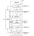
次に、この発明を実施するために使用する通信端末について説明する。図5は図1の船舶に搭載される通信端末120のハード構成例を示すブロック図である。図6は図5における無線通信部130の機能構成を示すブロック図である。図7は図5および図6に示した通信端末120によるこの発明に係る動作の流れを示すフロー・チャートである。 Next, a communication terminal used for carrying out the present invention will be described. FIG. 5 is a block diagram showing a hardware configuration example of the
通信端末120は図5に示すように、中央処理装置であるCPU122と、プログラムメモリであるROM124およびデータメモリであるRAM126等によって、マイクロ・コンピュータを構成している。さらに、操作部128、無線通信部130および有線通信I/F132を備えており、それらがCPUバス134によって互いに通信可能に接続されている。 As shown in FIG. 5, the
操作部128は、操船者によって操作されるスイッチやキーなどと、通信端末120の動作状態などを表示する表示器を有している。無線通信部130はアンテナ130aを有し、無線LAN機能によって他の船舶の通信端末および基地局と無線データ通信をするためのユニットである。有線通信I/F132は、図1および図3に示した船外機10のECU84と有線通信して、各種データを遣り取りするためのインターフェイスである。 The
この通信端末120における無線通信部130の機能構成について、図6によって説明する。無線通信部130は図6に示すように、コマンド送信部136、レスポンス受信部138、通信路確立部140、データ送受信部142、コマンド受信部144、およびレスポンス送信部146を備えており、それらが制御部148によって制御される。制御部148は、図5に示したCPU122とROM124およびRAM126等からなるマイクロ・コンピユータの機能に相当する。 A functional configuration of the
コマンド送信部136は、自船が通信ネットワークの構築を開始する場合に、基地局との接続を要求する接続要求コマンドを、通信可能範囲に在るどの船舶の通信端末でも受信できるようにブロードキャスト送信する。あるいは、自船より陸上4に近い側にある近隣の船舶に対して宛先を指定して順次送信してもよい。 The
また、コマンド受信部144が他船の通信端末から送信された接続要求コマンドを受信した場合にも、コマンド送信部136が同様に基地局との接続を要求する接続要求コマンドを送信する。それらの接続要求コマンドには、発信元となる自己のIDを付加する。 Also, when the
レスポンス受信部138は、コマンド送信部136が接続要求コマンドを送信した後、他船の通信端末から送信される接続要求OKのレスポンスを受信する。そのレスポンスを受信すると、それに付加されているIDによってその送信元(接続コマンドの受信元)を判別して、通信路確立部140に通知する。通信路確立部140は、その送信元の船舶の通信端末との間に相互に通信可能な通信路を確立し、そのIDを記憶する。 The
レスポンス受信部138が所定時間内に複数のレスポンスを受信した場合は、その各IDを通信路確立部140に順次通知し、通信路確立部140が、その各送信元の船舶の通信端末との間に通信路を順次確立して、その各IDを通信路を確立した順番と共に記憶する。それによって、順番が早い通信路を優先して使用できるようにする。 When the
データ送受信部142は、制御部148がECU84と通信して準備した自船の各種データを、通信路確立部140が確立した通信路を介して基地局宛に送信する。また、基地局から送信される自船宛の各種データを、確立した通信路を介して受信して制御部148に渡す。 The data transmission /
コマンド受信部144は、他船が通信ネットワークの構築を開始する場合に、他船の通信端末が送信する基地局との接続を要求する接続要求コマンドを受信すると、その接続要求コマンドに付加されているIDによってその発信元を判別して、レスポンス送信部146に通知する。それによって、レスポンス送信部146がそのIDが示す発信元に対して接続要求OKのレスポンスを送信する。 When receiving a connection request command for requesting a connection with a base station transmitted by a communication terminal of another ship when the other ship starts construction of a communication network, the
そして、コマンド受信部144またはレスポンス送信部146が通信路確立部140にそのIDを通知し、通信路確立部140がそのIDが示す発信元の通信端末との間の通信路を確立し、そのIDを記憶する。制御部148は、これらの各部を統括的に制御する。 Then, the
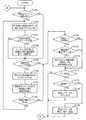
以下、図7のフロー・チャートを参照して、上述のように構成された通信端末120によるこの発明に係る動作の流れを説明する。なお、図7および以下の説明において、処理ステップを「S」と略記する。また、図7において、各判断処理結果の肯定を「YES」、否定を「NO」で示している。2か所のターミナル「A」は流れ線の接続箇所を示している。 Hereinafter, with reference to the flow chart of FIG. 7, the flow of the operation according to the present invention by the
通信端末120の電源スイッチが投入されて通信端末120が動作を開始すると、先ず、S150で通信ネットワーク構築指示がなされているかを判断する。自船が通信ネットワークの構築を開始する場合は、操船者が図5に示した操作部128の通信ネットワーク構築開始ボタンを押すなどによってそれを指示する。その指示の有無を図6に示した制御部148がチェックして、図7におけるS150の判断をする。 When the power switch of the
通信ネットワーク構築指示がなされていれば、S150で肯定と判断し、S152へ進み、基地局との接続を要求する接続要求コマンドに自己のIDを付加して送信する。その送信は、通信可能範囲に在るどの船舶の通信端末でも受信できるようにブロードキャスト送信するとよいが、前述したように適宜宛先を指定して送信してもよい。 If a communication network construction instruction has been given, it is determined affirmative in S150, the process proceeds to S152, and the transmission request command for requesting connection to the base station is added with its own ID and transmitted. The transmission may be broadcast transmission so that it can be received by any ship communication terminal in the communicable range, but may be transmitted by designating an appropriate destination as described above.
その後S154へ進み、所定時間内に他船の通信端末から接続要求OKのレスポンスを受信したか否かを判断し、受信するとS154で肯定と判断してS156へ進む。そして、受信したレスポンスに付加されていたIDによってその送信元(接続コマンドの受信元)を判別して、レスポンスを送信した船舶の通信端末との間に相互に通信可能な通信路を確立し、そのIDを記憶する。 Thereafter, the process proceeds to S154, where it is determined whether or not a response to the connection request OK has been received from the communication terminal of the other ship within a predetermined time. If received, the determination is affirmative in S154 and the process proceeds to S156. Then, the transmission source (connection command reception source) is determined based on the ID added to the received response, and a communication channel is established that can communicate with the communication terminal of the ship that transmitted the response. The ID is stored.
このS154とS156の処理を所定時間繰り返して、その間に複数のレスポンスを受信した場合は、その各レスポンスを送信した船舶の通信端末との間に同様な通信路を順次確立することができる。図7ではその繰り返し処理の流れは図示を省略している。その場合は所定時間経過後にS158へ進む。また、最初に受信できたレスポンスの送信元の船舶の通信端末との間にだけ通信路を確立して、S158へ進むようにしてもよい。 When the processes of S154 and S156 are repeated for a predetermined time and a plurality of responses are received during that time, similar communication paths can be established sequentially with the communication terminal of the ship that transmitted each response. In FIG. 7, the flow of the repetition process is not shown. In this case, the process proceeds to S158 after a predetermined time has elapsed. Alternatively, a communication path may be established only with the communication terminal of the ship that has transmitted the response first, and the process may proceed to S158.
S154で所定時間内にレスポンスを受信しなかった場合も、否定と判断してS158へ進む。通信ネットワーク構築指示がなされていなかった場合は、S150で否定と判断し、S152〜S156をスキップしてS158へ進む。S158〜S164は、他船が通信ネットワーク構築を開始した場合の処理である。 If no response is received within the predetermined time in S154, it is determined as negative and the process proceeds to S158. If the communication network construction instruction has not been given, it is determined negative in S150, S152 to S156 are skipped, and the process proceeds to S158. S158 to S164 are processes when another ship starts construction of a communication network.
S158では、基地局との接続を要求する接続要求コマンドを受信したか否かを判断する。受信していなければ否定と判断してS166へ進むが、受信していれば肯定と判断してS160へ進み、その接続要求コマンドの送信元の船舶に接続要求OKのレスポンスを送信する。そして、S162に進んで、接続要求コマンド送信元の船舶の通信端末との間に相互に通信可能な通信路を確立して、その通信端末のIDを記憶する。 In S158, it is determined whether a connection request command for requesting connection with the base station has been received. If it has not been received, it is determined to be negative and the process proceeds to S166. If it has been received, it is determined to be affirmative and the process proceeds to S160, and a response of the connection request OK is transmitted to the ship that has transmitted the connection request command. And it progresses to S162 and establishes the communication path which can communicate mutually with the communication terminal of the ship of the connection request command transmission source, and memorize | stores ID of the communication terminal.
その後、S164へ進んで自船の位置情報をチェックし、自船が基地局と通信可能な圏内に在るか否かを判断する。圏内に在る場合は肯定と判断してS166へ進む。圏内に在る場合は、基地局との通信路が確立されているので、それ以上他船との新たな通信路を確立する必要がないためである。 Thereafter, the process proceeds to S164, where the position information of the ship is checked, and it is determined whether or not the ship is in a range where communication with the base station is possible. If it is within the vicinity, it is determined as affirmative and the process proceeds to S166. If it is within the vicinity, the communication path with the base station has been established, so that it is not necessary to establish a new communication path with another ship any more.
自船が圏内にない場合は、S164で否定と判断し、S152へ戻って前述と同様に、基地局との接続を要求する接続要求コマンドを送信する。その後、S154とS156で所定時間内にレスポンスを受信できた場合に、そのレスポンスを送信した船舶との間に通信路を確立する。そして、S158へ進んで、接続要求コマンドを受信していなければS166へ進み、受信していればS160へ進んで前述の処理を繰り返す。 If the ship is not within range, it is determined to be negative in S164, and the process returns to S152 to transmit a connection request command for requesting connection with the base station, as described above. After that, when a response can be received within a predetermined time in S154 and S156, a communication path is established with the ship that transmitted the response. Then, the process proceeds to S158. If the connection request command has not been received, the process proceeds to S166, and if it has been received, the process proceeds to S160 and the above-described processing is repeated.
S166〜S170は、自船のデータを基地局へ送信する場合の処理である。先ず、S166で自船データ送信指示があったか否かを判断する。自船データ送信指示は、操船者が図5に示した操作部128から指示することができる。また、特定の情報が発生したとき、あるいは予め設定した時刻や時間経過などによって自動的に自船データ送信指示を行うこともできる。 S166 to S170 are processes for transmitting own ship data to the base station. First, in S166, it is determined whether or not an own ship data transmission instruction has been issued. The own ship data transmission instruction can be instructed by the operator from the
自船データ送信指示があった場合はS166で肯定と判断し、S168へ進んで通信路が確立されているか否かを判断する。通信路が確立されていなければ否定と判断し、自船データを基地局に送信できないので、S170をスキップしてS172へ進む。通信路が確立されていれば、S168で肯定と判断してS170へ進み、確立されている通信路へ自船データを基地局宛に送信する。その後S172へ進む。 If there is an instruction to transmit own ship data, it is determined affirmative in S166, and the process proceeds to S168 to determine whether a communication path is established. If the communication path has not been established, it is determined to be negative and the ship data cannot be transmitted to the base station, so S170 is skipped and the process proceeds to S172. If the communication path has been established, it is determined to be affirmative in S168, and the process proceeds to S170, where the own ship data is transmitted to the established communication path to the base station. Thereafter, the process proceeds to S172.
自動データ送信指示がなされていなければS166で否定と判断し、S168およびS170をスキップしてS172へ進む。S172〜S178は、基地局から送信されたデータあるいは他船から送信されたデータを、基地局から直接あるいは他船との間に確立された通信路を介して受信する場合の処理である。まず、S172でデータを受信したか否かを判断し、データを受信すれば肯定と判断してS174へ進む。データを受信していなければ、S172で否定と判断して最初のS150へ戻る。 If an automatic data transmission instruction has not been given, a negative determination is made in S166, S168 and S170 are skipped, and the flow proceeds to S172. S172 to S178 are processes when data transmitted from the base station or data transmitted from another ship is received directly from the base station or via a communication path established with another ship. First, it is determined whether or not data is received in S172. If data is received, it is determined to be affirmative and the process proceeds to S174. If no data has been received, it is determined negative in S172, and the process returns to the first S150.
S174では受信したデータが自船宛データか否かを判断し、自船宛データであれば肯定と判断して、S176へ進んで受信したデータをメモリに保存した後、最初のS150へ戻る。したがって、基地局から自船宛のデータが送信され、それを確立された通信路を介して受信した場合は、そのデータを受け取ることができる。 In S174, it is determined whether or not the received data is data for the own ship. If the data is for the own ship, it is determined to be affirmative, the process proceeds to S176, and the received data is stored in the memory, and then the process returns to the first S150. Therefore, when the data addressed to the ship is transmitted from the base station and received through the established communication path, the data can be received.
受信したデータが自船宛データでなかった場合は、S174で否定と判断する。この場合は受信したデータが、他船から基地局宛に送信されたデータか、基地局から他船宛に送信されたデータであるから、S178に進んで、受信したデータをその宛先に向けて送信(転送)する。すなわち、この場合はデータ送信の中継をすることになる。その後、最初のS150へ戻る。 If the received data is not the data addressed to the ship, it is determined negative in S174. In this case, since the received data is data transmitted from the other ship to the base station or data transmitted from the base station to the other ship, the process proceeds to S178, and the received data is directed to the destination. Send (transfer). That is, in this case, data transmission is relayed. Thereafter, the process returns to the first S150.
この実施形態の各船舶に搭載された通信端末120は、上述した処理を電源がオフにされるまで繰り返し行っている。船舶群を構成する各船舶はそれぞれ個別に航行しているので、相互の位置関係が常に変化している。そのため、基地局にデータを送信したり、基地局に対してサーバが持つデータの送信を要求する場合には、その前に通信ネットワークの構築をやり直した方がよい。その他に、通信路を確立した各船舶の通信端末間での通信も当然行えるが、その説明は省略する。 The
ところで、船舶群を構成する各船舶は、図3で説明したようにそれぞれGPS受信機80を備えており、それがGPS衛星から送信される船舶の位置を示すGPS信号を受信し、その受信信号に基づいてECU84が、常に自船の現在位置を検出している。しかし、GPS受信機を備えていない船舶や、備えていてもそのGPS受信機が故障してしまったような場合には、自船の現在位置を知ることができない。 By the way, each ship which comprises a ship group is equipped with the
そのような場合に、図4によって説明した実施形態のように、船舶群を構成する各船舶間で相互に通信可能な通信路を確立していれば、近隣の他の複数の船舶からその各位置情報を送信してもらうことによって、自船の現在の位置情報を推測することができる。 In such a case, as in the embodiment described with reference to FIG. 4, if a communication path capable of mutual communication is established between the respective ships constituting the group of ships, each of the other neighboring ships is connected to each of them. By having the position information transmitted, the current position information of the ship can be estimated.
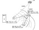
その位置情報推測の例を以下に説明する。図8は位置情報推測の一例を説明するための説明図、図9は位置情報推測の他の例を説明するための説明図である。なお、図8および図9と以下の説明では、各船舶を簡略化して単に「船」と記し、その符号をA〜CまたはA〜Dとしているが、これらの船は、図1に示した船舶1および図4に示した船舶1A〜1G等に相当するものである。 An example of the position information estimation will be described below. FIG. 8 is an explanatory diagram for explaining an example of position information estimation, and FIG. 9 is an explanatory diagram for explaining another example of position information estimation. In FIG. 8 and FIG. 9 and the following description, each ship is simplified and described simply as “ship”, and the reference numerals thereof are A to C or A to D. These ships are shown in FIG. This corresponds to the
また、GPS衛星400からGPS信号を受信するのはGPS受信機80であり、そのGPS信号によって位置情報を検出するのはECU84であり、その位置情報を送信するのは通信端末120であるが、説明を簡単にするため、位置情報が分かる船がそれらを行うこととして説明する。同様に各船から送信される位置情報を受信し、その各位置情報と受信方向の角度差から自船の現在の位置情報を推測するのは通信端末120であるが、それらを位置情報が分からない船が行うこととして説明する。 The
図8に示す例は、位置情報が分からない船Cが近隣の2艘の船Aと船Bから位置情報を受信して、自船の現在の位置情報を推測する場合である。 The example shown in FIG. 8 is a case where a ship C whose position information is unknown receives position information from two neighboring ships A and B and estimates the current position information of the ship.
例えば、ある時点で、船AがGPS衛星からのGPS信号を受信して、現在の位置の緯度が北緯11度11分11.111秒、経度が東経111度11分11.111秒であることを知り、その位置情報を船Cに向けて送信する。同時に、船Bも衛星からのGPS信号を受信して、現在の位置の緯度が北緯9度9分09.000秒、経度が東経122度22分22.222秒であることを知り、その位置情報を船Cに向けて送信する。 For example, ship A receives a GPS signal from a GPS satellite at a certain point, and the latitude of the current position is 11 degrees 11 minutes 11.111 seconds north latitude and 111 degrees 11 minutes 11.111 seconds longitude. And the position information is transmitted to the ship C. At the same time, Ship B also received the GPS signal from the satellite and found that the latitude of the current position is 9 degrees 9 minutes 09.000 seconds north latitude and
その船Aおよび船Bの各位置情報を、船Cが指向性アンテナを備えた通信端末でそれぞれ受信し、その各位置情報と受信した方向の角度差α(指向性アンテナの回転角度の差による)とから、自船の現在の位置情報を、例えば緯度が北緯12度12分12.120秒、経度が東経133度13分33.333秒であると推測することができる。 Each position information of the ship A and the ship B is received by the communication terminal provided with the directional antenna by the ship C, and the angle difference α between the position information and the received direction (depending on the difference in the rotation angle of the directional antenna). ), It can be estimated that the current position information of the ship is, for example, the latitude is 12
図9に示す例は、位置情報が分からない船Dが近隣の3艘の船A、船B、船Cから位置情報を受信して、自船の現在の位置情報を推測する場合である。 The example shown in FIG. 9 is a case where a ship D whose position information is not known receives position information from the neighboring three ships A, B and C and estimates the current position information of the ship.
例えば、ある時点で、船AがGPS衛星からのGPS信号を受信して、現在の位置の緯度が北緯11度11分11.111秒、経度が東経111度11分11.111秒であることを知り、その位置情報を船Dに向けて送信する。同時に、船Bも衛星からのGPS信号を受信して、現在の位置の緯度が北緯9度9分09.000秒、経度が東経122度22分22.222秒であることを知り、その位置情報を船Dに向けて送信する。同時に、船Cも衛星からのGPS信号を受信して、現在の位置の緯度が北緯10度10分10.100秒、経度が東経144度14分44.444秒であることを知り、その位置情報を船Dに向けて送信する。 For example, ship A receives a GPS signal from a GPS satellite at a certain point, and the latitude of the current position is 11 degrees 11 minutes 11.111 seconds north latitude and 111 degrees 11 minutes 11.111 seconds longitude. And the position information is transmitted to the ship D. At the same time, Ship B also received the GPS signal from the satellite and found that the latitude of the current position is 9 degrees 9 minutes 09.000 seconds north latitude and
その各位置情報を、船Dが指向性アンテナを備えた通信端末でそれぞれ受信し、その各位置情報と受信した方向の角度差α,β(それぞれ指向性アンテナの回転角度の差による)とから、自船の現在の位置情報を、例えば緯度が北緯12度12分12.120秒、経度が東経133度13分33.333秒のように推測することができる。 Each position information is received by the communication terminal equipped with a directional antenna by the ship D, and from each position information and the angle difference α, β (respectively due to the difference in the rotation angle of the directional antenna). The current position information of the ship can be estimated such that the latitude is 12
図8における船Cおよび図9における船Dに搭載される通信端末は、他船のうちの複数の船舶の通信端末から送信される各船舶の位置情報をそれぞれ指向性アンテナによって受信して、その各位置情報を取得すると共に該各位置情報の受信角度差を検出する位置情報受信部と、該位置情報受信部によって取得した各位置情報と検出した受信角度差とによって、自船の位置情報を推測する位置情報推測部とを有している。 The communication terminal mounted on the ship C in FIG. 8 and the ship D in FIG. 9 receives the position information of each ship transmitted from the communication terminals of a plurality of ships among the other ships by the directional antenna. The position information of the ship is obtained by the position information receiving unit that acquires each position information and detects the reception angle difference of each position information, and the position information acquired by the position information receiving unit and the detected reception angle difference. A position information estimation unit for estimation.
図5に示した通信端末120では、その位置情報受信部は図6に示した無線通信部130のデータ送受信部142の機能として有し、位置情報推測部は制御部148(図5に示したCPU122、ROM124、RAM126によるマイクロ・コンピユータ)の機能として有する。 In the
上述した如く、この実施形態にあっては、海上2を航行する自船(図4の例では船舶1A)と複数艘の他船(図4の例では1B〜1G)からなる船舶群の各船舶1A〜1Gにそれぞれ搭載された無線データ通信用の通信端末120によって、自船1Aから基地局200に通信するための通信ネットワーク構築方法であって、自船1Aの通信端末120が、他船のうちの少なくとも基地局200と通信可能な圏内200aに存在する船舶1Gを含む船舶1B〜1Gの通信端末120との間で通信ネットワークを構築して相互に通信可能な通信路を確立すると共に、自船1Aの通信端末はその確立された通信路を介して基地局200と通信する如く構成した。それによって、各船舶に搭載する通信端末に電波強度の強い無線端末を使用する必要がないので安価になる。しかも、自船が基地局200から離れていても、リアルタイムで基地局とデータの送受信が可能である。 As described above, in this embodiment, each ship group consisting of the own ship (
また、前記通信ネットワークを構築する際に、自船1Aと基地局200と通信可能な圏内に存在する船舶1Gおよび該船舶1Gと自船1Aとの間に介在する船舶1B,1F等のそれぞれ通信端末間で、送信元の通信端末から接続要求コマンドを送信し、該接続要求コマンドを受信した受信元の通信端末が前記送信元の通信端末に接続要求OKのレスポンスを送信し、該送信元の通信端末が該レスポンスを受信することによって前記受信元の通信端末との間に相互に通信可能な通信路を確立することを順次行う如く構成した。それによって、自船1Aと基地局200と通信可能な圏内に存在する船舶1Gとの間の通信ネットワークを、素早く確実に構築することができる。 Further, when the communication network is constructed, the
前記船舶群の各船舶1A〜1Gのすべての通信端末間で、直接または他の船舶の通信端末を介して相互に通信可能な通信路を確立する如く構成すれば、船舶群を構成する船舶1A〜1G間で必要に応じて各種のデータを交換することができる。それによって、例えば、ある船舶のTAセンサ(吸気温センサ)などの入力デバイスが故障した場合、一番近い船舶の入力値を採用できるため、代替値の精度を高めることができる。また、ある船でフェールセーフ(F/S)が働いたとき、近くの船が素早く救助に行くこともできる。 If a communication path is established between all the communication terminals of the
この発明による通信端末の実施形態にあっては、海上を航行する自船と複数艘の他船からなる船舶群の各船舶1A〜1Gにそれぞれ搭載される無線データ通信用の通信端末120であって、陸上の基地局200への接続を要求する接続要求コマンドを他船の通信端末120に対して送信するコマンド送信部136と、その接続要求コマンドの送信後に、他船のいずれかの通信端末120から送信される接続要求OKのレスポンスを受信するレスポンス受信部138と、そのレスポンス受信部138が前記レスポンスを受信した場合に、そのレスポンスを送信した通信端末120との間に相互の通信路を確立する通信路確立部140と、他船のいずれかの通信端末120から送信される接続要求コマンドを受信するコマンド受信部144と、そのコマンド受信部144が接続要求コマンドを受信した場合に、その接続コマンドを送信した通信端末120に対して接続要求OKのレスポンスを送信すると共に、コマンド送信部136に接続要求コマンドを送信させるレスポンス送信部146と、前記通信路を確立した船舶1B,1Fおよび基地局200と通信可能な圏内に存在する船舶1Gの各通信端末120を介して基地局200と通信してデータを送受信するデータ送受信部142とを有する如く構成した。上記船舶群の各船舶1A〜1Gにそれぞれこの通信端末を搭載することによって、上述した通信ネットワークを素早く確実に構築することができる。 In the embodiment of the communication terminal according to the present invention, there is a
さらに、位置情報が分からない船舶(図8の船Cあるいは図9の船D)の通信端末120が、複数の船舶(図8の船A,B、あるいは図9の船A,B,C)の各通信端末120から送信される各船舶の位置情報を、それぞれ指向性アンテナによって受信して、その各位置情報を取得すると共に該各位置情報の受信角度差(αまたはα,β)を検出する位置情報受信部(図6のデータ送受信部142の機能)と、その位置情報受信部によって取得した各位置情報と検出した受信角度差とによって、自船の位置情報を推測する位置情報推測部(図6の制御部148の機能)とを有する如く構成すれば、GPS受信機を備えていないか故障して位置情報が分からない船舶も、近隣の他の複数の船舶からその各位置情報を送信してもらうことによって、自船の現在の位置情報を推測することができる。 Furthermore, the
上述した通信端末120のハードウエアとして、スマートフォンや携帯電話、タブレット端末、PDA、携帯型パソコン等の各種のデータ通信可能な端末装置を利用することができる。その場合、その端末装置のCPUが無線通信部等を制御して、図7に示したフロー・チャートによって説明した処理を実行できるように、そのプログラムをROM等の内部メモリに格納しておくことが必要である。 As the hardware of the
以上、この発明の実施形態について説明してきたが、その実施形態の各部の具体的な構成や処理の内容等は、そこに記載したものに限るものではない。また、この発明は上述した実施形態に限定されるものではなく、特許請求の範囲の各請求項に記載された技術的特徴を有する以外は、何ら限定されるものではないことは言うまでもない。さらに、以上説明してきた実施形態の構成例および動作例等は、適宜変更または追加したり一部を削除してもよく、相互に矛盾しない限り任意に組み合わせて実施することも可能であることは勿論である。 As mentioned above, although embodiment of this invention was described, the specific structure of each part of the embodiment, the content of a process, etc. are not restricted to what was described there. Further, the present invention is not limited to the above-described embodiment, and it is needless to say that the present invention is not limited in any way except for having the technical features described in the claims. Furthermore, the configuration examples and operation examples of the embodiments described above may be changed or added as appropriate, or a part of them may be deleted, and can be implemented in any combination as long as they are not mutually contradictory. Of course.
1,1A〜1G(小型)船舶、2 海上、2a 所定海域、4 陸上、10 船外機(10A 第1船外機、10B 第2船外機)、12 船体、12a 船尾、12b 船首、30 エンジン(内燃機関)、60 プロペラ、80 GPS受信機、82 方位センサ、84 ECU(電子制御ユニット)、90 操縦席、92 ステアリングホイール、96 ダッシュボード、120 通信端末、130 無線通信部、200 基地局、200a 基地局と通信可能な圏内、300 クラウド、310 サーバ、400 GPS衛星
1,1A-1G (small) ship, 2 sea, 2a predetermined sea area, 4 land, 10 outboard motor (10A first outboard motor, 10B second outboard motor), 12 hull, 12a stern, 12b bow, 30 Engine (internal combustion engine), 60 propeller, 80 GPS receiver, 82 direction sensor, 84 ECU (electronic control unit), 90 cockpit, 92 steering wheel, 96 dashboard, 120 communication terminal, 130 wireless communication unit, 200
Claims (5)
Translated fromJapanese前記自船の前記通信端末が、前記他船のうちの少なくとも前記基地局と通信可能な圏内に存在する船舶を含む船舶の前記通信端末との間で通信ネットワークを構築して相互に通信可能な通信路を確立すると共に、前記自船の通信端末は前記確立された通信路を介して前記基地局と通信することを特徴とする海上における通信ネットワーク構築方法。A communication network construction method for communicating from the ship to a base station on land by a communication terminal for wireless data communication mounted on each ship of a ship group consisting of a ship that sails on the sea and a plurality of other ships. There,
The communication terminal of the own ship can communicate with each other by constructing a communication network with the communication terminal of the ship including the ship that exists in a range where at least the base station can communicate with the other ship. A communication network construction method at sea, wherein a communication channel is established, and a communication terminal of the ship communicates with the base station via the established communication channel.
陸上の基地局への接続を要求する接続要求コマンドを前記他船の通信端末に対して送信するコマンド送信部と、
該接続要求コマンドの送信後に、前記他船のいずれかの通信端末から送信される接続要求OKのレスポンスを受信するレスポンス受信部と、
該レスポンス受信部が前記レスポンスを受信した場合に、該レスポンスを送信した通信端末との間に相互の通信路を確立する通信路確立部と、
前記他船のいずれかの通信端末から送信される接続要求コマンドを受信するコマンド受信部と、
該コマンド受信部が前記接続要求コマンドを受信した場合に、該接続要求コマンドを送信した通信端末に対して接続要求OKのレスポンスを送信すると共に、前記コマンド送信部に接続要求コマンドを送信させるレスポンス送信部と、
前記通信路を確立した通信端末および前記基地局と通信可能な圏内に存在する船舶の通信端末とを介して前記基地局と通信してデータを送受信するデータ送受信部と
を有することを特徴とする通信端末。A communication terminal for wireless data communication mounted on each ship of a ship group consisting of a ship that sails on the sea and a plurality of other ships,
A command transmission unit that transmits a connection request command for requesting connection to a land base station to the communication terminal of the other ship;
A response receiving unit that receives a response of a connection request OK transmitted from any communication terminal of the other ship after the transmission of the connection request command;
A communication path establishment unit that establishes a mutual communication path with the communication terminal that has transmitted the response when the response reception unit receives the response;
A command receiving unit for receiving a connection request command transmitted from any communication terminal of the other ship;
When the command receiving unit receives the connection request command, a response transmission that transmits a connection request OK response to the communication terminal that has transmitted the connection request command and causes the command transmission unit to transmit a connection request command. And
A data transmission / reception unit configured to communicate with the base station via a communication terminal that establishes the communication path and a communication terminal of a ship that exists in a communication area with the base station, and to transmit and receive data. Communication terminal.
The position information of each ship transmitted from the communication terminals of a plurality of ships among the other ships is received by the directional antenna, and the respective position information is acquired and the reception angle difference between the position information is detected. The position information receiving unit, and a position information estimating unit that estimates the position information of the ship based on each position information acquired by the position information receiving unit and the detected reception angle difference. 4. The communication terminal according to 4.
Priority Applications (2)
| Application Number | Priority Date | Filing Date | Title |
|---|---|---|---|
| JP2017064061AJP2018166318A (en) | 2017-03-29 | 2017-03-29 | Maritime communication network construction method and communication terminal |
| US15/933,286US10433357B2 (en) | 2017-03-29 | 2018-03-22 | Marine telecommunications network building system and telecommunications terminal for small boats |
Applications Claiming Priority (1)
| Application Number | Priority Date | Filing Date | Title |
|---|---|---|---|
| JP2017064061AJP2018166318A (en) | 2017-03-29 | 2017-03-29 | Maritime communication network construction method and communication terminal |
Publications (2)
| Publication Number | Publication Date |
|---|---|
| JP2018166318Atrue JP2018166318A (en) | 2018-10-25 |
| JP2018166318A5 JP2018166318A5 (en) | 2020-04-16 |
Family
ID=63670366
Family Applications (1)
| Application Number | Title | Priority Date | Filing Date |
|---|---|---|---|
| JP2017064061APendingJP2018166318A (en) | 2017-03-29 | 2017-03-29 | Maritime communication network construction method and communication terminal |
Country Status (2)
| Country | Link |
|---|---|
| US (1) | US10433357B2 (en) |
| JP (1) | JP2018166318A (en) |
Cited By (2)
| Publication number | Priority date | Publication date | Assignee | Title |
|---|---|---|---|---|
| JP2024517198A (en)* | 2022-04-01 | 2024-04-19 | 上海海事大学 | Network architecture based on D2D communication to extend maritime communication range |
| JP7709712B1 (en)* | 2024-08-21 | 2025-07-17 | 株式会社Oceanic Constellations | Control system, control method, and program |
Families Citing this family (5)
| Publication number | Priority date | Publication date | Assignee | Title |
|---|---|---|---|---|
| GB201905361D0 (en)* | 2019-04-16 | 2019-05-29 | Rolls Royce Plc | Vehicle convoy control |
| US11208188B2 (en) | 2019-06-10 | 2021-12-28 | Polaris Industries Inc. | Thruster arrangement for a boat |
| EP4034957A4 (en) | 2019-09-27 | 2023-12-27 | Polaris Industries Inc. | SYSTEM AND METHOD FOR POSITIONING A WATERCRAFT |
| US12179889B2 (en) | 2020-07-06 | 2024-12-31 | Polaris Industries Inc. | Boat maneuverability and stability control systems and methods |
| WO2022056917A1 (en)* | 2020-09-21 | 2022-03-24 | Telefonaktiebolaget Lm Ericsson (Publ) | Method, apparatus for enhancing coverage of network |
Citations (6)
| Publication number | Priority date | Publication date | Assignee | Title |
|---|---|---|---|---|
| JP2005286756A (en)* | 2004-03-30 | 2005-10-13 | Toyota Motor Corp | Mobile communication path selection method, wireless communication apparatus, and mobile |
| JP2006234683A (en)* | 2005-02-25 | 2006-09-07 | National Univ Corp Shizuoka Univ | Positioning system |
| WO2011055512A1 (en)* | 2009-11-04 | 2011-05-12 | 川崎重工業株式会社 | Maneuvering control method and maneuvering control system |
| JP2011170769A (en)* | 2010-02-22 | 2011-09-01 | Wakayama Univ | Location information collection system |
| JP2011170768A (en)* | 2010-02-22 | 2011-09-01 | Fuji Xerox Co Ltd | System and device for information, introduction processing device and program |
| JP2014096665A (en)* | 2012-11-08 | 2014-05-22 | Mitsubishi Electric Corp | Self-supporting array antenna system, and array antenna configuration method |
Family Cites Families (4)
| Publication number | Priority date | Publication date | Assignee | Title |
|---|---|---|---|---|
| JP3437990B2 (en) | 2000-03-17 | 2003-08-18 | インターナショナル・ビジネス・マシーンズ・コーポレーション | Communication method, communication terminal, wireless ad hoc network, and mobile phone |
| IL214867A0 (en)* | 2011-08-29 | 2012-01-31 | Elta Systems Ltd | Moving cellular communicatio system |
| AU2014262897B2 (en)* | 2013-05-04 | 2018-03-22 | Christopher Decharms | Mobile security technology |
| US10045227B2 (en)* | 2016-02-09 | 2018-08-07 | Amrita Vishwa Vidyapeetham | Mobile infrastructure for coastal region offshore communications and networks |
- 2017
- 2017-03-29JPJP2017064061Apatent/JP2018166318A/enactivePending
- 2018
- 2018-03-22USUS15/933,286patent/US10433357B2/enactiveActive
Patent Citations (6)
| Publication number | Priority date | Publication date | Assignee | Title |
|---|---|---|---|---|
| JP2005286756A (en)* | 2004-03-30 | 2005-10-13 | Toyota Motor Corp | Mobile communication path selection method, wireless communication apparatus, and mobile |
| JP2006234683A (en)* | 2005-02-25 | 2006-09-07 | National Univ Corp Shizuoka Univ | Positioning system |
| WO2011055512A1 (en)* | 2009-11-04 | 2011-05-12 | 川崎重工業株式会社 | Maneuvering control method and maneuvering control system |
| JP2011170769A (en)* | 2010-02-22 | 2011-09-01 | Wakayama Univ | Location information collection system |
| JP2011170768A (en)* | 2010-02-22 | 2011-09-01 | Fuji Xerox Co Ltd | System and device for information, introduction processing device and program |
| JP2014096665A (en)* | 2012-11-08 | 2014-05-22 | Mitsubishi Electric Corp | Self-supporting array antenna system, and array antenna configuration method |
Cited By (3)
| Publication number | Priority date | Publication date | Assignee | Title |
|---|---|---|---|---|
| JP2024517198A (en)* | 2022-04-01 | 2024-04-19 | 上海海事大学 | Network architecture based on D2D communication to extend maritime communication range |
| JP7570021B2 (en) | 2022-04-01 | 2024-10-21 | 上海海事大学 | Network architecture based on D2D communication to extend maritime communication range |
| JP7709712B1 (en)* | 2024-08-21 | 2025-07-17 | 株式会社Oceanic Constellations | Control system, control method, and program |
Also Published As
| Publication number | Publication date |
|---|---|
| US10433357B2 (en) | 2019-10-01 |
| US20180288821A1 (en) | 2018-10-04 |
Similar Documents
| Publication | Publication Date | Title |
|---|---|---|
| JP2018166318A (en) | Maritime communication network construction method and communication terminal | |
| JP6892775B2 (en) | Ship maneuvering assist system and its ship maneuvering assist device and server | |
| JP6797730B2 (en) | Ship maneuvering assist system and its maneuvering assist device and server | |
| JP6466600B1 (en) | Propeller control device | |
| JP6770471B2 (en) | Small vessel maneuvering assist system | |
| US20210139123A1 (en) | Ship Propulsion System and Ship | |
| JP6427694B1 (en) | Navigation assistance system for ships | |
| US8622777B1 (en) | Systems and methods for controlling trim and maneuvering a marine vessel | |
| US11611651B2 (en) | Calling system and method for personal watercraft | |
| US10049582B2 (en) | Small boat collision avoidance apparatus | |
| JP6911161B2 (en) | Ship maneuvering support device and outboard motor | |
| JP2013103526A (en) | Small vessel | |
| CN112929890A (en) | Wireless communication method and system based on ship networking and satellite hybrid networking | |
| US6801839B2 (en) | Control parameter selecting apparatus for boat and sailing control system equipped with this apparatus | |
| WO2020012602A1 (en) | Outboard motor control system | |
| JP2012185154A (en) | Moving body control device, method and program by gps signal as well as mobile station management system, method and program using the same | |
| JP2022085660A (en) | Systems and methods for controlling ships | |
| JPWO2004047335A1 (en) | Communications system | |
| JP5279739B2 (en) | Wireless communication system | |
| JP6908405B2 (en) | Small vessel failure prediction system | |
| KR20190071402A (en) | Wirelessly auto steering system for ship | |
| JP2019058141A (en) | Fishing information providing system | |
| JP5337730B2 (en) | Wireless communication system | |
| US20240199178A1 (en) | Fishing site information providing system, fishing site information providing method, and server | |
| CH720332A2 (en) | Hydrofoil transport system |
Legal Events
| Date | Code | Title | Description |
|---|---|---|---|
| A521 | Request for written amendment filed | Free format text:JAPANESE INTERMEDIATE CODE: A523 Effective date:20200306 | |
| A621 | Written request for application examination | Free format text:JAPANESE INTERMEDIATE CODE: A621 Effective date:20200306 | |
| A977 | Report on retrieval | Free format text:JAPANESE INTERMEDIATE CODE: A971007 Effective date:20201113 | |
| A131 | Notification of reasons for refusal | Free format text:JAPANESE INTERMEDIATE CODE: A131 Effective date:20201124 | |
| A131 | Notification of reasons for refusal | Free format text:JAPANESE INTERMEDIATE CODE: A131 Effective date:20210209 | |
| A521 | Request for written amendment filed | Free format text:JAPANESE INTERMEDIATE CODE: A523 Effective date:20210303 | |
| A131 | Notification of reasons for refusal | Free format text:JAPANESE INTERMEDIATE CODE: A131 Effective date:20210427 | |
| A02 | Decision of refusal | Free format text:JAPANESE INTERMEDIATE CODE: A02 Effective date:20211109 |