JP2018155646A - Surface measuring device and surface measurement method - Google Patents
Surface measuring device and surface measurement methodDownload PDFInfo
- Publication number
- JP2018155646A JP2018155646AJP2017053513AJP2017053513AJP2018155646AJP 2018155646 AJP2018155646 AJP 2018155646AJP 2017053513 AJP2017053513 AJP 2017053513AJP 2017053513 AJP2017053513 AJP 2017053513AJP 2018155646 AJP2018155646 AJP 2018155646A
- Authority
- JP
- Japan
- Prior art keywords
- measured
- distance sensor
- height difference
- measurement
- region
- Prior art date
- Legal status (The legal status is an assumption and is not a legal conclusion. Google has not performed a legal analysis and makes no representation as to the accuracy of the status listed.)
- Granted
Links
Images


Landscapes
- Length Measuring Devices By Optical Means (AREA)
Abstract
Translated fromJapaneseDescription
Translated fromJapanese本発明は、微小な凹凸の高低差を測定する表面測定装置及び表面測定方法に関する。 The present invention relates to a surface measuring apparatus and a surface measuring method for measuring a height difference of minute unevenness.
特許文献1には、2次元カメラの焦点を合わせることにより焦点位置の差から、欠陥の高低差を測定する被測定物の表面における欠陥検査方法が記載されている。
ところで、特許文献1の技術では、三角測距方式で深さを算出しているので、凹凸の斜面角度によっては、反射光の計測に誤差が生じ、精度向上の要望があった。 By the way, in the technique of
そこで、特許文献2に記載の白色同軸共焦点方式によれば、凹凸の斜面角度の影響が抑制された状態で、微小な凹凸の高低差を測定できる。 Therefore, according to the white coaxial confocal method described in
しかしながら、特許文献2に記載の白色同軸共焦点方式では、微小な凹凸の高低差を測定できるが故に、測定値が、実際にある表面の凹凸の高低差であるのか、表面の凹凸ではなくノイズデータであるのか、判別がつきにくい。ノイズデータを誤って、微小な凹凸の高低差と認識すると、被測定物の表面に、実際にはない凹凸(ゴースト)があると認識される可能性がある。 However, since the white coaxial confocal method described in
本発明の目的は、被測定物の表面に、実際にある凹凸の高低差を測定可能な表面測定装置及び表面測定方法を提供することにある。 An object of the present invention is to provide a surface measuring apparatus and a surface measuring method capable of measuring the height difference of the unevenness actually present on the surface of the object to be measured.
本発明の一態様に係る表面測定装置は、被測定物の表面の高低差を測定する距離センサと、前記被測定物に対する前記距離センサの相対位置が相対的に移動するように走査する走査駆動装置と、前記被測定物に対する前記距離センサの相対移動量と、前記距離センサの測定値から前記被測定物の表面の位置座標を求め、前記距離センサの測定値を、前記位置座標に基づいて前記距離センサが測定した測定平面上の位置における画像の階調として変換処理し、前記画像の階調に応じて、所定面積以上の面積があるとされた前記画像内の塊領域を含む領域を高低差測定領域とし、前記高低差測定領域の被測定物の表面の高低差データを出力する演算装置と、を備える。 A surface measurement apparatus according to an aspect of the present invention includes a distance sensor that measures a height difference of a surface of a measurement object, and a scanning drive that performs scanning so that a relative position of the distance sensor relative to the measurement object moves relatively. A position coordinate of the surface of the object to be measured is obtained from an apparatus, a relative movement amount of the distance sensor with respect to the object to be measured, and a measurement value of the distance sensor, and the measurement value of the distance sensor is calculated based on the position coordinate. A region including a mass region in the image that is converted as a gradation of an image at a position on a measurement plane measured by the distance sensor and has an area of a predetermined area or more according to the gradation of the image. And an arithmetic device that outputs height difference data of the surface of the object to be measured in the height difference measurement area.
この態様によれば、実際にある凹凸が特定され、実際にある凹凸の領域のみに絞って高低差データが出力される。その結果、実際に凹凸がない領域を誤認する可能性が低減される。 According to this aspect, the actual unevenness is specified, and the height difference data is output only on the actual uneven region. As a result, the possibility of misidentifying a region that does not actually have unevenness is reduced.
望ましい態様として、前記被測定物に対する前記距離センサの相対移動量のピッチが、前記距離センサの照射する光のスポット径の1/2以下である。これにより、距離センサが測定した測定平面上の位置の分解能が向上する。その結果、高低差測定領域内の測定点が増えるので、精度の高い凹凸の高低差を測定可能になる。 As a desirable mode, the pitch of the relative movement amount of the distance sensor with respect to the object to be measured is ½ or less of the spot diameter of light irradiated by the distance sensor. Thereby, the resolution of the position on the measurement plane measured by the distance sensor is improved. As a result, since the number of measurement points in the height difference measurement region increases, it becomes possible to measure the height difference of the unevenness with high accuracy.
望ましい態様として、前記演算装置は、前記画像を2値化処理して、前記塊領域を抽出する。これにより、実際にある凹凸の高低差のデータと、ノイズデータとを区別できる。 As a desirable mode, the arithmetic unit binarizes the image and extracts the mass region. As a result, it is possible to distinguish the actually uneven height difference data from the noise data.
望ましい態様として、前記距離センサは、白色同軸共焦点方式により、被測定物の表面の高低差を測定する。これにより、凹凸の斜面角度の影響が抑制された状態で、微小な凹凸の高低差を測定できる。 As a desirable mode, the distance sensor measures the height difference of the surface of the object to be measured by a white coaxial confocal method. Thereby, the height difference of a minute unevenness | corrugation can be measured in the state in which the influence of the inclined angle of the unevenness | corrugation was suppressed.
本発明の一態様に係る表面測定装置は、被測定物の表面の高低差を測定する、白色同軸共焦点方式の距離センサと、前記被測定物に対する前記距離センサの相対位置を相対的に移動させる走査駆動装置と、を含み、前記被測定物に対する前記距離センサの相対移動量のピッチが、前記距離センサの照射する光のスポット径の1/2以下である。 A surface measurement apparatus according to an aspect of the present invention includes a white coaxial confocal distance sensor that measures a difference in height of a surface of an object to be measured, and a relative position of the distance sensor relative to the object to be measured. The pitch of the relative movement amount of the distance sensor with respect to the object to be measured is ½ or less of the spot diameter of the light irradiated by the distance sensor.
この態様によれば、これにより、距離センサが測定した測定平面上の位置の分解能が向上する。その結果、連続的に変化する距離センサの測定値が、不連続となる大きな値があれば、ノイズとして判断し、高低差のデータとして取り扱わないようにすることができる。 According to this aspect, this improves the resolution of the position on the measurement plane measured by the distance sensor. As a result, if the measurement value of the distance sensor that changes continuously is a discontinuous large value, it can be determined as noise and not handled as height difference data.
本発明の一態様に係る表面測定方法は、被測定物の表面の高低差を測定する距離センサの相対位置が被測定物に対して相対的に移動するように走査し、前記表面の位置座標を求める走査ステップと、前記距離センサの測定値を、前記位置座標に基づいて前記距離センサが測定した測定平面上の位置における画像の階調として変換処理する階調変換処理ステップと、前記画像の階調に応じて、所定面積以上の面積があるとされた前記画像内の塊領域を含む領域を高低差測定領域として特定する高低差測定領域特定ステップと、前記高低差測定領域の被測定物の表面の高低差データを出力する高低差出力ステップと、を含む。 In the surface measurement method according to one aspect of the present invention, scanning is performed so that the relative position of the distance sensor that measures the height difference of the surface of the object to be measured moves relative to the object to be measured, and the position coordinates of the surface are measured. A scanning step for obtaining a distance, a gradation conversion processing step for converting a measurement value of the distance sensor as a gradation of an image at a position on a measurement plane measured by the distance sensor based on the position coordinates, A height difference measurement region specifying step for specifying, as a height difference measurement region, a region including a mass region in the image that is determined to have an area of a predetermined area or more according to the gradation, and an object to be measured in the height difference measurement region A height difference output step for outputting height difference data of the surface of the surface.
この態様によれば、実際にある凹凸が特定され、実際にある凹凸の領域のみに絞って高低差データが出力される。その結果、実際に凹凸がない領域を誤認する可能性が低減される。 According to this aspect, the actual unevenness is specified, and the height difference data is output only on the actual uneven region. As a result, the possibility of misidentifying a region that does not actually have unevenness is reduced.
望ましい態様として、同軸落射式の照明により、法線方向から被測定物の表面を照射し、法線方向に配置された撮像装置で撮像する撮像ステップと、前記撮像ステップで撮像したデータを演算装置で処理して、該被測定物の表面における凹凸の位置を特定する位置特定ステップと、をさらに含み、前記走査ステップにおいて、前記位置特定ステップにおいて特定した凹凸の位置を走査対象領域とし、前記走査対象領域の前記表面の位置座標を求める。これにより、予め凹凸の位置を高速に特定し、特定された凹凸の位置に対して、精度の高い高低差データが出力される。 As a desirable mode, an imaging step of irradiating the surface of the object to be measured from the normal direction with coaxial epi-illumination, and imaging with an imaging device arranged in the normal direction, and an arithmetic unit for the data captured in the imaging step And a position specifying step for specifying the position of the unevenness on the surface of the object to be measured, wherein in the scanning step, the position of the unevenness specified in the position specifying step is set as a scanning target region, and the scanning is performed. The position coordinates of the surface of the target area are obtained. As a result, the position of the unevenness is specified in advance at high speed, and highly accurate height difference data is output for the specified uneven position.
本発明によれば、被測定物の表面に、実際にある凹凸の高低差を測定可能な表面測定装置及び表面測定方法を提供することができる。 ADVANTAGE OF THE INVENTION According to this invention, the surface measuring apparatus and surface measuring method which can measure the height difference of the unevenness | corrugation which are actually on the surface of a to-be-measured object can be provided.
以下、本発明を実施するための形態(以下、実施形態という)につき、図面を参照しつつ説明する。なお、下記の実施形態により本発明が限定されるものではない。また、下記実施形態における構成要素には、当業者が容易に想定できるもの、実質的に同一のもの、いわゆる均等の範囲のものが含まれる。さらに、下記実施形態で開示した構成要素は適宜組み合わせることが可能である。 Hereinafter, modes for carrying out the present invention (hereinafter referred to as embodiments) will be described with reference to the drawings. In addition, this invention is not limited by the following embodiment. In addition, constituent elements in the following embodiments include those that can be easily assumed by those skilled in the art, those that are substantially the same, and those in a so-called equivalent range. Furthermore, the constituent elements disclosed in the following embodiments can be appropriately combined.
図1は、表面測定装置の全体構成を示す模式図である。図2は、被測定領域を説明するための説明図である。図3は、表面測定装置の概略構成を示す模式図である。図4は、白色同軸共焦点方式の距離センサを説明するための説明図である。以下、図1から図4を適宜参照して、表面測定装置1を説明する。 FIG. 1 is a schematic diagram showing the overall configuration of the surface measuring apparatus. FIG. 2 is an explanatory diagram for explaining a region to be measured. FIG. 3 is a schematic diagram showing a schematic configuration of the surface measuring apparatus. FIG. 4 is an explanatory diagram for explaining a white coaxial confocal distance sensor. Hereinafter, the
(実施形態1)
図1に示すように、表面測定装置1は、被測定物9の表面を測定する装置である。表面測定装置1は、測定ユニット2と、測定ユニット2を固定する支持部3と、演算装置10とを有している。(Embodiment 1)
As shown in FIG. 1, the
被測定物9は、例えば、熱可塑性樹脂のシートである。例えば、熱可塑性樹脂は、ポリカーボネート系樹脂、アクリル系樹脂、ポリエステル系樹脂、アクリロニトリル・ブタジエン・スチレン樹脂(ABS)、アクリロニトリル・エチレン−プロピレン−ジエン・スチレン樹脂(AES)、アクリロニトリル・スチレン・アクリレート樹脂(ASA)、塩化ビニル樹脂、ポリエチレン、ポリプロピレン等のポリオレフィン系樹脂や、これらを2種類以上組み合わせた樹脂、又はこれらの樹脂に繊維や微粒子を加えて形成されている。 The
図1に示すように、被測定物9の一部が走査対象領域SAとなる。実施形態1においては、被測定物9がシート状であるので、走査対象領域SAは、図2に示すように平面である。 As shown in FIG. 1, a part of the
図3において、走査対象領域SAの平面の一方向がX方向とされ、走査対象領域SAの平面においてX方向と直交する方向がY方向とされ、X−Y平面に直交する方向がZ方向とされている。 In FIG. 3, one direction of the plane of the scan target area SA is the X direction, the direction perpendicular to the X direction is the Y direction in the plane of the scan target area SA, and the direction perpendicular to the XY plane is the Z direction. Has been.
測定ユニット2は、白色同軸共焦点方式の距離センサ21と、X方向駆動装置22、Y方向駆動装置23及びZ方向駆動装置24を備えている。 The
X方向駆動装置22、Y方向駆動装置23及びZ方向駆動装置24は、それぞれ独立駆動して、被測定物9の走査対象領域SAに対する距離センサ21の相対位置を相対的に移動させる走査駆動装置である。X方向駆動装置22、Y方向駆動装置23及びZ方向駆動装置24は、電動モータ、ピエゾ素子などで、距離センサ21が搭載しているステージを、X方向、Y方向及びZ方向に移動させることができる。 The X
例えば、Z方向駆動装置が駆動することで、走査対象領域SAに対する距離センサ21のZ方向の位置が設定される。次に、図2及び図3に示すように、距離センサ21が照射する光のビームスポットBSが、一定期間X方向に移動して走査する。次に、Y方向駆動装置23と、X方向駆動装置22とが協働して動作することで、距離センサ21が照射する光のビームスポットBSが、一定期間X方向及びY方向に移動して走査する。そして、上述した走査動作が繰り返され、矢印SCANの軌跡を描いて、距離センサ21が照射する光のビームスポットBSが走査対象領域SAを走査する。 For example, the position of the
図4に示すように、白色同軸共焦点方式の距離センサ21は、白色光源兼受光部211と、レンズ212とを備える。白色光源兼受光部211は、白色光源の機能と、受光の機能とが同軸に配置されている。白色光源兼受光部211は、白色光を発光する。白色光源兼受光部211からの白色光は、レンズ212により、複数の波長WV1、WV2、WV3のそれぞれの軸上の異なる高さで焦点を結ぶように、被測定物9へ照射される。白色光源兼受光部211が、被測定物9の表面で焦点を結んだ波長WV2の光だけを測定できるので、複数の波長WV1、WV2、WV3に応じた、距離センサ21と被測定物9の表面までの距離が測定できる。 As shown in FIG. 4, the white coaxial
図1に示すように、X方向駆動装置22、Y方向駆動装置23及びZ方向駆動装置24により移動した、被測定物9の走査対象領域SAに対する距離センサ21の相対移動量は、演算装置10へ入力される。また、距離センサ21の測定値も演算装置10へ入力される。 As shown in FIG. 1, the relative movement amount of the
演算装置10は、いわゆるコンピュータであり、入力インターフェースと、出力インターフェースと、CPU(Central Processing Unit)と、ROM(Read Only Memory)と、RAM(Random Access Memory)と、記憶部16と、を有している。入力インターフェースには、距離センサ21が接続されており、出力インターフェースには、表示装置19が接続されている。CPU、ROM、RAM及び記憶部16は、バスで接続されている。ROMには、BIOS(Basic Input Output System)等のプログラムが記憶されている。記憶部16は、例えばHDD(Hard Disk Drive)やフラッシュメモリ等であり、オペレーティングシステムプログラムやアプリケーションプログラムを記憶している。CPUは、演算手段であり、RAMをワークエリアとして使用しながらROMや記憶部16に記憶されているプログラムを実行することにより、XY座標取得部11、Z座標取得部12、階調変換処理部13、画像処理部14、XYZ座標演算部15の機能を実現する。記憶部16は、内蔵であっても外付けであってもよく、RAMを一時記憶として使ってもよく、あるいは、ネットワーク上の記憶装置やサーバ等であってもよい。 The
図5Aは、比較例において表面の凹部の測定を説明するための説明図である。図5に示す比較例は、三角測距方式と呼ばれ、光源、測定対象、受光部が三角形の位置に配置され、測定対象で結像する位置で距離が測定できる。このため、対象物が凹部(又は凸部)であると、凹部(又は凸部)の傾斜部分で、反射角度が変化し、反射光の計測に誤差が生じる可能性がある。 FIG. 5A is an explanatory diagram for explaining measurement of a concave portion on a surface in a comparative example. The comparative example shown in FIG. 5 is called a triangulation system, and the light source, the measurement object, and the light receiving unit are arranged at triangular positions, and the distance can be measured at a position where the image is formed on the measurement object. For this reason, when the object is a concave portion (or convex portion), the reflection angle changes at the inclined portion of the concave portion (or convex portion), and an error may occur in the measurement of reflected light.
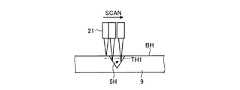
図5Bは、実施形態1において表面の凹部の測定を説明するための説明図である。距離センサ21は、光源と受光部とは同軸に配置されている。このため、凹部5Hの傾斜角度の影響を受けにくい。このため、被測定物9に対して、矢印SCANの方向に距離センサ21が相対移動して走査しながら、高低差を計測すれば、表面の基準距離(地合い)BHに対する凹部5Hの深さが連続的に測定できる。 FIG. 5B is an explanatory diagram for explaining the measurement of the recesses on the surface in the first embodiment. In the
図5Cは、実施形態1において表面の凸部の測定を説明するための説明図である。距離センサ21は、光源と受光部とは同軸に配置されている。このため、凸部5Pの傾斜角度の影響を受けにくい。このため、被測定物9に対して、矢印SCANの方向に距離センサ21が相対移動して走査しながら、高低差を計測すれば、面の基準距離(地合い)BHに対する凸部5Pの高さが連続的に測定できる。 FIG. 5C is an explanatory diagram for explaining the measurement of the convex portions on the surface in the first embodiment. In the
図6は、距離センサのスポット径と走査ピッチとの関係を説明するための説明図である。X方向駆動装置22、Y方向駆動装置23の少なくとも1つの駆動装置は、被測定物に対する距離センサの相対移動量のピッチPが、距離センサの照射する光のスポット直径Dの1/2以下であるように、矢印SCANの方向に走査する。これにより、XY平面における分解能が向上する。その結果、連続的に変化する距離センサ21の測定値が、不連続となる大きな値があれば、ノイズとして判断し、高低差のデータとして取り扱わないようにすることができる。被測定物に対する距離センサの相対移動量のピッチPは、距離センサの照射する光のスポット直径Dの1/2、1/3、1/4又は1/5のいずれかの値をとり得るが、小さくなるほど、処理時間がかかる。 FIG. 6 is an explanatory diagram for explaining the relationship between the spot diameter of the distance sensor and the scanning pitch. In at least one of the X
距離センサ21は、1μm以上100μm以下の微小な凹凸の高低差を検出することができる。ここで、被測定物9の走査対象領域SAに対する距離センサ21の相対移動により、被測定物9の走査対象領域SAの表面が走査されると、XY平面における距離センサ21の測定値の面分布データを取得できる。XY平面における距離センサ21の測定値の面分布データには、実際にある表面の凹部5H又は凸部5Pの高低差の測定値も含むが、ノイズデータも含んでしまう。ノイズデータは、実際にある表面の凹部5H又は凸部5Pの高低差の測定値と大きく異なる大きな値のノイズデータであれば、ノイズデータの除去が可能である。しかしながら、実際にある表面の凹部5H又は凸部5Pの高低差の測定値のばらつきの範囲内に含まれる測定値がノイズとして含まれてしまう。ノイズデータを誤って、微小な凹凸の高低差と認識すると、被測定物9の表面に、実際にはない凹凸(ゴースト)があると認識されると、測定自体が成り立たなくなる。 The
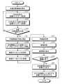
そこで、被測定物9の表面に、実際にある凹凸の高低差であるのか、実際にはない凹凸なのかを図1、図3、図7及び図8を参照しつつ説明する。図7は、実施形態1の表面測定方法のフローチャートである。図8は、表面測定結果の変換処理例を示す説明図である。 Therefore, whether the surface of the
図7に示すように、XY座標取得部11及びZ座標取得部12は、X方向駆動装置22を駆動させ、X方向走査中の座標(X,Y,Z)データを取得する(ステップS11)。座標(X,Y,Z)データは、X方向、Y方向及びZ方向の座標からなるXYZ座標系の3次元座標である。座標(X,Y)は、X方向駆動装置22、Y方向駆動装置23に取り付けられた位置センサ、又はエンコーダなどの位置データがXY座標取得部11に送られ、XY座標取得部11が座標(X,Y)を取得できる。Z座標取得部12は、座標(X,Y)の場合の距離センサ21の測定値を座標Zとして取得する。実施形態1において、座標Zの値は、被測定物9の表面における高低差のデータである。 As shown in FIG. 7, the XY coordinate
次に、XY座標取得部11及びZ座標取得部12は、X方向駆動装置22及びY方向駆動装置23を駆動させ、X方向及びY方向走査中の座標(X,Y,Z)データを取得する(ステップS12)。 Next, the XY coordinate
次に、XY座標取得部11及びZ座標取得部12は、図2に示す走査対象領域SAの全部を終了していない場合は、ステップS11に処理を戻す(ステップS13、No)。XY座標取得部11は、図2に示す走査対象領域SAの全部を終了している場合は、ステップS14に処理を進める(ステップS13、Yes)。以上、ステップS11、S12、S13の処理を繰り返すことにより、被測定物9の表面の高低差を測定する距離センサ21の相対位置が被測定物9に対して相対的に移動するように走査し、表面の位置座標を求める走査ステップが処理される。表面測定装置1が走査対象領域SA全部を走査できれば、走査方向の向きは限定されない。 Next, the XY coordinate
次に、XY座標取得部11及びZ座標取得部12は、所定閾値以上の座標(X,Y,Z)データをノイズデータとして削除する(ステップS14)。実際にある表面の凹部5H又は凸部5Pの高低差の測定値と大きく異なる、所定の閾値を超えた大きな値のノイズデータであれば、ノイズデータの除去が可能である。ここで、所定の閾値を超えないノイズデータが、実際にはない表面の凹凸として認識される可能性がある。このため、実施形態1の表面測定方法は、以下に説明するステップS15以降の処理を実行する。 Next, the XY coordinate
XY座標取得部11及びZ座標取得部12は、記憶部16に、ステップS14のノイズ除去済みの座標(X,Y,Z)データをマスターデータとして保存する(ステップS15)。 The XY coordinate
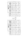
次に、階調変換処理部13は、マスターデータの座標(X,Y,Z)データのうち、Z座標データの値(z1からznの値)を階調の値(t1からtn)に変換する(ステップS16)。階調は、8ビットの階調を使ってもよいし、16ビットの階調を使ってもよいし、24ビットの階調を使ってもよい。ビット数の多い階調ほど、分解能が高くなる。 Next, the gradation
図8に示すように、例えば、データIDが、1からnの座標(X,Y,Z)データが記憶部16に記憶されている。階調変換処理部13は、データIDに対するX座標データと、Y座標データは変更せず、Z座標データのみを階調データへ変換する。例えば、Z座標データz1からznは、各距離の大きさに応じて、階調t1からtnにそれぞれ変換される。これにより、距離センサ21の測定値は、XY平面上の位置が特定された画像の階調に変換される。その結果、変換後は、画像データとして処理できる。このように、ステップS16の階調変換処理ステップによれば、距離センサ21の測定値が、座標(X,Y,Z)データ(位置座標)に基づいて距離センサ21が測定した測定平面上の位置(座標(X,Y))における画像の階調として変換する。 As shown in FIG. 8, for example, coordinate (X, Y, Z) data having a data ID of 1 to n is stored in the
そこで、画像処理部14は、ステップS16で得られた画像データに、既知の画像前処理をする(ステップS17)。画像前処理としては、平滑化処理、フィルタ処理、強調処理、鮮明化処理などである。ステップS17は、省略することもできる。 Therefore, the image processing unit 14 performs known image preprocessing on the image data obtained in step S16 (step S17). Image preprocessing includes smoothing processing, filter processing, enhancement processing, sharpening processing, and the like. Step S17 can be omitted.
次に、画像処理部14は、ステップS17において画像前処理した画像に画像処理を行う(ステップS18)。ステップS18の画像処理は、例えば、表面の基準距離(地合い)BHに対する基準閾値TH1(図5B参照)を境界として、ステップS17で得られた画像データを2値化処理する。あるいは、表面の基準距離(地合い)BHに対する基準閾値TH2(図5C参照)を境界として、ステップS17で得られた画像データを2値化処理する。 Next, the image processing unit 14 performs image processing on the image preprocessed in step S17 (step S18). In the image processing in step S18, for example, the image data obtained in step S17 is binarized using the reference threshold value TH1 (see FIG. 5B) for the reference distance (texture) BH of the surface as a boundary. Alternatively, the image data obtained in step S17 is binarized using the reference threshold TH2 (see FIG. 5C) for the reference distance (texture) BH of the surface as a boundary.
図9は、画像処理上の塊領域と、高低差測定領域との関係を示す説明図である。画像処理部14は、2値化した画像から、図9に示す塊領域SPを抽出する(ステップS19)。塊領域SPは、周囲(地合い)とは異なる色(例えば、白)の領域である。塊領域SPは、上述した凹部5H又は凸部5Pの領域に対応する。 FIG. 9 is an explanatory diagram showing a relationship between a mass area in image processing and an elevation difference measurement area. The image processing unit 14 extracts the block region SP shown in FIG. 9 from the binarized image (step S19). The lump area SP is an area having a color (for example, white) different from the surrounding area (texture). The lump region SP corresponds to the region of the
ステップS18において、2値化処理の代わりに、背景差分処理を行ってもよい。背景差分処理を行う場合には、凹凸のない背景画像データが予め記憶部16に記憶されている。画像処理部14は、記憶部16に記憶されている凹凸のない背景画像データと、ステップS17で得られた画像データとの差分を抽出し、生成した差分画像を記憶部16に記憶する。次に、画像処理部14は、差分画像から図9に示す塊領域SPを抽出する。 In step S18, a background difference process may be performed instead of the binarization process. When performing the background difference process, background image data without unevenness is stored in the
ステップS14で除去しきれない、ノイズデータは、ステップS18の画像処理により、基準面積を下回る点又は、小面積のノイズデータとなることが多い。 In many cases, the noise data that cannot be removed in step S14 becomes noise data that is smaller than the reference area or small in area by the image processing in step S18.
画像処理部14は、面積ASが基準面積以上ではない場合(ステップS20、No)、ノイズとして除去する。 When the area AS is not equal to or larger than the reference area (No at Step S20), the image processing unit 14 removes the noise as noise.
画像処理部14は、面積ASが基準面積以上である場合(ステップS20、Yes)、処理をステップS21へ進める。 If the area AS is equal to or larger than the reference area (step S20, Yes), the image processing unit 14 advances the processing to step S21.
次に、XYZ座標演算部15は、図9に示す、塊領域SPの重心CGを基準として、フィレ径FDxよりも所定量以上大きな測定範囲MDxと、フィレ径FDyよりも所定量以上大きな測定範囲MDyとで囲まれる範囲を高低差測定領域PPとする。そして、XYZ座標演算部15は、高低差測定領域PP内に特定された階調データの座標(X,Y)を出力する(ステップS21)。実施形態1において、高低差測定領域PPは、矩形であるが、塊領域SPを内部に含む領域であれば、どのような外形状であってもよい。例えば、高低差測定領域PPは、塊領域SPを内部に含み、重心CGを中心とした円形であってもよい。 Next, the XYZ coordinate
次に、XYZ座標演算部15は、ステップS21で出力された座標(X,Y)に対応する座標(X,Y,Z)をステップS15で記憶部16に記憶したマスターデータの座標(X,Y,Z)データから抽出して、高低差測定領域PPの座標(X,Y,Z)データを出力する(ステップS22)。 Next, the XYZ coordinate
XYZ座標演算部15は、ステップS21において、高低差測定領域PP内に特定された階調データのデータIDを出力し、ステップS22において、ステップS21で出力されたデータIDに基づいて、ステップS15で記憶部16に記憶したマスターデータの座標(X,Y,Z)データから抽出して、高低差測定領域PPの座標(X,Y,Z)データを出力するようにしてもよい。 In step S21, the XYZ coordinate
以上説明したように、表面測定装置1は、距離センサ21と、X方向駆動装置22、Y方向駆動装置23及びZ方向駆動装置24で構成された走査駆動装置と、演算装置10を備えている。演算装置10は、被測定物9に対する距離センサ21の相対移動量と、距離センサ21の測定値から被測定物9に対する距離センサ21の相対位置座標、すなわちマスターデータの座標(X,Y,Z)データを求める。演算装置10は、距離センサ21の測定値を、上述した相対移動量で測定平面上の位置(座標(X,Y))が特定される画像の階調として変換処理する。演算装置10は、画像の階調に応じて、所定面積AS以上の面積があるとされた画像内の塊領域SPを含む領域を高低差測定領域PPとし、この高低差測定領域PPの被測定物9の表面の高低差データを出力する。例えば、表示装置19は、高低差測定領域PPの被測定物9の表面の高低差をグラフィック表示する。 As described above, the
これにより、被測定物9の表面に、実際に凹凸がある高低差測定領域PPのみに絞って高低差データが出力されるので、実際に凹凸がない領域を誤認する可能性が低減される。 Thereby, since the height difference data is output only on the height difference measurement region PP that actually has unevenness on the surface of the
(実施形態2)
図10は、被測定物の被検査領域が円筒の円筒表面である場合を説明する説明図である。図11は、同軸落射式距離センサを説明するための模式図である。図12は、同軸落射式距離センサが測定する測定領域と、白色同軸共焦点方式の距離センサが測定する測定領域との関係を説明するための模式図である。図13は、実施形態2の表面測定方法のフローチャートである。実施形態2では、実施形態1とは異なり、被測定物が円筒であり、表面が円筒周面である。なお、上述した実施形態1で説明したものと同じ構成要素、には同一の符号を付して重複する説明は省略する。また、図13に示すステップの処理は、図7に示すステップの処理と同じ処理の場合は同じ符号を付して、説明を省略する。(Embodiment 2)
FIG. 10 is an explanatory diagram for explaining a case where the inspection region of the object to be measured is a cylindrical surface of a cylinder. FIG. 11 is a schematic diagram for explaining the coaxial incident distance sensor. FIG. 12 is a schematic diagram for explaining the relationship between the measurement region measured by the coaxial incident distance sensor and the measurement region measured by the white coaxial confocal distance sensor. FIG. 13 is a flowchart of the surface measurement method according to the second embodiment. In the second embodiment, unlike the first embodiment, the object to be measured is a cylinder and the surface is a cylindrical circumferential surface. Note that the same components as those described in the first embodiment are denoted by the same reference numerals, and redundant description is omitted. Further, the processing of the step shown in FIG. 13 is denoted by the same reference numeral in the case of the same processing as the processing of the step shown in FIG.
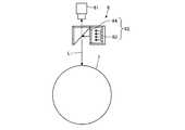
図10に示すように同軸落射式の表面測定装置6及び実施形態1において説明した表面測定装置1が被測定物7の表面を測定する。被測定物7は、円筒形状を有している。被測定物7は、転写体と呼ばれるローラであり、例えばシートを搬送する際に用いられる。 As shown in FIG. 10, the coaxial incident surface measurement device 6 and the
表面測定装置6は、内部に上述したX方向駆動装置22、Y方向駆動装置23及びZ方向駆動装置24と同じ機構を備えている。また、被測定物7が円筒であるので、被測定物7を回転させる回転駆動装置がY方向の走査駆動装置となる。 The surface measuring device 6 includes the same mechanism as the
図11に示すように、照明62は、光源63と、ハーフミラー64と、を有する。光源63は、LED(Light Emitting Diode)などの発光体を有する。光源63は、ハーフミラー64を介して被測定物7に垂直に照明光Lを入射させる。被測定物7の円筒周面で反射した照明光Lは、撮像装置61に入射する。照明62は、撮像装置61の光軸の方向から照明光Lを被測定物7に入射させる同軸落射照明である。表面測定装置6は、同軸落射式の照明により、法線方向から被測定物7の表面を照射し、法線方向に配置された撮像装置61で表面の状態を撮像する。 As shown in FIG. 11, the
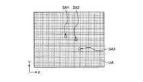
図12に示すように、表面測定装置6は、撮像単位UA毎に、凹凸があるかどうかを、表面測定装置1よりも高速に走査できる。図13に示すように、表面測定装置6は、撮像装置61で撮像したデータを、表面測定装置1へ送信する。表面測定装置1は、演算装置10で処理して、被測定物7の表面における凹凸の位置を特定する(ステップS1)。例えば、表面測定装置1は、撮像単位UA毎に、凹凸があり高低差を確認するべき走査対象領域SA1、SA2及びSA3を特定する。次に、表面測定装置1は、走査対象領域SA1、SA2及びSA3のそれぞれについて、図13に示すステップS11の処理を時分割で処理する。 As shown in FIG. 12, the surface measuring device 6 can scan at higher speed than the
実施形態2において、被測定物7が円筒であり、表面が円筒周面である。このため、ステップS11、S12、S13の処理を繰り返すことにより、走査ステップが処理されても、座標(X,Y,Z)データは、円筒周面の曲率の影響を受ける。このため、演算装置10は、円筒周面の曲率の影響が相殺されるように、ステップS13の処理後の座標(X,Y,Z)データに、円筒周面を平面とする補正係数をかける。これにより、ステップS15で保存される座標(X,Y,Z)データは、実施形態1のXYZ座標系と同じ処理が可能となる。実施形態2において、座標Zの値は、被測定物7の表面における高低差のデータである。 In the second embodiment, the
以上説明したように、実施形態2において、表面測定方法は、同軸落射式の照明により、法線方向から被測定物9の表面を照射し、法線方向に配置された撮像装置で撮像する撮像ステップと、撮像ステップで撮像したデータを演算装置10で処理して、該被測定物9の表面における凹凸の位置を特定する位置特定ステップと、をさらに含む。そして、ステップS11、S12、S13の処理を繰り返すことによる走査ステップにおいて、位置特定ステップにおいて特定した凹凸の位置を走査対象領域SA1、SA2、SA3とし、走査対象領域SA1、SA2、SA3のいずれかの表面の座標(X,Y,Z)データを求める。これにより、表面測定装置6が予め凹凸の位置を高速に特定し、特定された凹凸の位置に対して、表面測定装置1が精度の高い高低差データを出力する。 As described above, in the second embodiment, the surface measurement method irradiates the surface of the
以上、好適な実施形態を説明したが、本発明はこのような実施形態に限定されるものではない。実施の形態で開示された内容はあくまで一例にすぎず、本発明の趣旨を逸脱しない範囲で種々の変更が可能である。本発明の趣旨を逸脱しない範囲で行われた適宜の変更についても、当然に本発明の技術的範囲に属する。上述した発明を基にして当業者が適宜設計変更して実施しうる全ての発明も、本発明の要旨を包含する限り、本発明の技術的範囲に属する。 The preferred embodiments have been described above, but the present invention is not limited to such embodiments. The content disclosed in the embodiment is merely an example, and various modifications can be made without departing from the spirit of the present invention. Appropriate changes made without departing from the spirit of the present invention naturally belong to the technical scope of the present invention. All the inventions that can be implemented by those skilled in the art based on the above-described inventions are also within the technical scope of the present invention as long as they include the gist of the present invention.
一般的に「シート」とは、JISにおける定義上、薄く、一般にその厚みが長さと幅のわりには小さく平らな製品をいい、一般的に「フィルム」とは、長さ及び幅に比べて厚みが極めて小さく、最大厚みが任意に限定されている薄い平らな製品で、通常、ロールの形で供給されるものをいい(日本工業規格JISK6900)、しかし、シートとフィルムの境界は定かでなく、実施形態1においては両者を同義として用い、統一して「シート」と記す。 “Sheet” is generally a thin product as defined by JIS and generally has a thickness that is small and flat for the length and width. In general, “film” is a thickness compared to the length and width. Is a thin flat product with an extremely small maximum thickness, and is usually supplied in the form of a roll (Japanese Industrial Standard JISK6900). However, the boundary between the sheet and the film is not clear, In the first embodiment, both are used synonymously and are collectively referred to as “sheet”.
1、6 表面測定装置
2 測定ユニット
3 支持部
5H 凹部
5P 凸部
7、9 被測定物
10 演算装置
11 XY座標取得部
12 Z座標取得部
13 階調変換処理部
14 画像処理部
15 XYZ座標演算部
16 記憶部
19 表示装置
21 距離センサ
22 X方向駆動装置
23 Y方向駆動装置
24 Z方向駆動装置
61 撮像装置
62 照明
63 光源
64 ハーフミラー
211 白色光源
212 レンズ
AS 面積
BS ビームスポット
D スポット直径
FDx、FDy フィレ径
ID データ
MDx、MDy 測定範囲
PP 高低差測定領域
SA、SA1、SA2、SA3 走査対象領域
SP 塊領域
PP 高低差測定領域DESCRIPTION OF
Claims (7)
Translated fromJapanese前記被測定物に対する前記距離センサの相対位置が相対的に移動するように走査する走査駆動装置と、
前記被測定物に対する前記距離センサの相対移動量と、前記距離センサの測定値から前記被測定物の表面の位置座標を求め、
前記距離センサの測定値を、前記位置座標に基づいて前記距離センサが測定した測定平面上の位置における画像の階調として変換処理し、
前記画像の階調に応じて、所定面積以上の面積があるとされた前記画像内の塊領域を含む領域を高低差測定領域とし、
前記高低差測定領域の表面の高低差データを出力する演算装置と、を備えることを特徴とする表面測定装置。A distance sensor that measures the height difference of the surface of the object to be measured;
A scanning drive device that scans so that the relative position of the distance sensor with respect to the object to be measured moves relatively;
The relative movement amount of the distance sensor with respect to the object to be measured and the position coordinates of the surface of the object to be measured from the measured value of the distance sensor,
The measured value of the distance sensor is converted as a gradation of an image at a position on the measurement plane measured by the distance sensor based on the position coordinates,
According to the gradation of the image, a region including a mass region in the image that is said to have an area of a predetermined area or more is an elevation difference measurement region,
A surface measuring device comprising: an arithmetic device that outputs height difference data of the surface of the height difference measuring region.
前記被測定物に対する前記距離センサの相対位置を相対的に移動させる走査駆動装置と、を含み、
前記被測定物に対する前記距離センサの相対移動量のピッチが、前記距離センサの照射する光のスポット径の1/2以下であることを特徴とする表面測定装置。A white coaxial confocal distance sensor that measures the height difference of the surface of the object to be measured;
A scanning drive device that relatively moves the relative position of the distance sensor with respect to the object to be measured,
A surface measuring apparatus, wherein a pitch of a relative movement amount of the distance sensor with respect to the object to be measured is ½ or less of a spot diameter of light irradiated by the distance sensor.
前記距離センサの測定値を、前記位置座標に基づいて前記距離センサが測定した測定平面上の位置における画像の階調として変換処理する階調変換処理ステップと、
前記画像の階調に応じて、所定面積以上の面積があるとされた前記画像内の塊領域を含む領域を高低差測定領域として特定する高低差測定領域特定ステップと、
前記高低差測定領域の被測定物の表面の高低差データを出力する高低差出力ステップと、
を含むことを特徴とする表面測定方法。A scanning step of scanning the relative position of the distance sensor for measuring the height difference of the surface of the object to be measured to move relative to the object to be measured, and obtaining the position coordinates of the surface;
A gradation conversion processing step for converting the measurement value of the distance sensor as a gradation of an image at a position on a measurement plane measured by the distance sensor based on the position coordinates;
A height difference measurement region specifying step for specifying a region including a mass region in the image that has an area of a predetermined area or more as the height difference measurement region according to the gradation of the image,
A height difference output step for outputting height difference data of the surface of the object to be measured in the height difference measurement region;
A surface measurement method comprising:
前記撮像ステップで撮像したデータを演算装置で処理して、該被測定物の表面における凹凸の位置を特定する位置特定ステップと、をさらに含み、
前記走査ステップにおいて、前記位置特定ステップにおいて特定した凹凸の位置を走査対象領域とし、前記走査対象領域の前記表面の位置座標を求めることを特徴とする請求項6に記載の表面測定方法。An imaging step of irradiating the surface of the object to be measured from the normal direction with coaxial epi-illumination and imaging with an imaging device arranged in the normal direction;
Processing the data imaged in the imaging step with an arithmetic device, and further including a position specifying step for specifying the position of the unevenness on the surface of the object to be measured,
The surface measurement method according to claim 6, wherein in the scanning step, the position of the unevenness specified in the position specifying step is set as a scanning target region, and the position coordinates of the surface of the scanning target region are obtained.
Priority Applications (1)
| Application Number | Priority Date | Filing Date | Title |
|---|---|---|---|
| JP2017053513AJP6841109B2 (en) | 2017-03-17 | 2017-03-17 | Surface measuring device and surface measuring method |
Applications Claiming Priority (1)
| Application Number | Priority Date | Filing Date | Title |
|---|---|---|---|
| JP2017053513AJP6841109B2 (en) | 2017-03-17 | 2017-03-17 | Surface measuring device and surface measuring method |
Publications (2)
| Publication Number | Publication Date |
|---|---|
| JP2018155646Atrue JP2018155646A (en) | 2018-10-04 |
| JP6841109B2 JP6841109B2 (en) | 2021-03-10 |
Family
ID=63715703
Family Applications (1)
| Application Number | Title | Priority Date | Filing Date |
|---|---|---|---|
| JP2017053513AActiveJP6841109B2 (en) | 2017-03-17 | 2017-03-17 | Surface measuring device and surface measuring method |
Country Status (1)
| Country | Link |
|---|---|
| JP (1) | JP6841109B2 (en) |
Cited By (5)
| Publication number | Priority date | Publication date | Assignee | Title |
|---|---|---|---|---|
| CN112611763A (en)* | 2019-09-20 | 2021-04-06 | 深圳市腾盛精密装备股份有限公司 | Transparent body detection method and system based on spectrum confocal |
| JP7001184B1 (en) | 2021-03-03 | 2022-01-19 | オムロン株式会社 | Work shape measurement system |
| WO2022185740A1 (en)* | 2021-03-03 | 2022-09-09 | オムロン株式会社 | Workpiece shape measurement device, workpiece shape measurement system, workpiece shape measurement method, and workpiece shape measurement program |
| CN116507449A (en)* | 2020-11-25 | 2023-07-28 | 发那科株式会社 | display device |
| CN119223216A (en)* | 2024-11-29 | 2024-12-31 | 河海大学 | A method for measuring the flatness of prefabricated pavement panels based on machine vision |
Citations (12)
| Publication number | Priority date | Publication date | Assignee | Title |
|---|---|---|---|---|
| JPH05164702A (en)* | 1991-12-17 | 1993-06-29 | Toshiba Corp | Surface inspecting device |
| JPH095046A (en)* | 1995-06-21 | 1997-01-10 | Takaoka Electric Mfg Co Ltd | 3D shape measuring device |
| JPH10222608A (en)* | 1997-02-06 | 1998-08-21 | Toyota Motor Corp | Character inspection method and apparatus |
| JPH112611A (en)* | 1997-06-11 | 1999-01-06 | Hitachi Ltd | Method for manufacturing sheet-like member, method for inspecting sheet-like member, and defect inspection apparatus for sheet-like member |
| JP2003042737A (en)* | 2001-07-26 | 2003-02-13 | Toray Ind Inc | Cut workpiece inspecting method |
| JP2003279317A (en)* | 2002-03-22 | 2003-10-02 | Olympus Optical Co Ltd | Height measuring device |
| JP2004101532A (en)* | 2002-09-12 | 2004-04-02 | Siemens Ag | Confocal distance sensor |
| JP2006125967A (en)* | 2004-10-28 | 2006-05-18 | Lasertec Corp | Inspection apparatus, inspection method, and pattern substrate manufacturing method using the same |
| JP2006258726A (en)* | 2005-03-18 | 2006-09-28 | Ricoh Co Ltd | Defect inspection method |
| JP2008196872A (en)* | 2007-02-09 | 2008-08-28 | Lasertec Corp | Inspection apparatus and inspection method, pattern substrate manufacturing method |
| JP2010002758A (en)* | 2008-06-20 | 2010-01-07 | Olympus Corp | Confocal scanning type microscopic system |
| US20150026646A1 (en)* | 2013-07-18 | 2015-01-22 | Korea Electronics Technology Institute | User interface apparatus based on hand gesture and method providing the same |
- 2017
- 2017-03-17JPJP2017053513Apatent/JP6841109B2/enactiveActive
Patent Citations (12)
| Publication number | Priority date | Publication date | Assignee | Title |
|---|---|---|---|---|
| JPH05164702A (en)* | 1991-12-17 | 1993-06-29 | Toshiba Corp | Surface inspecting device |
| JPH095046A (en)* | 1995-06-21 | 1997-01-10 | Takaoka Electric Mfg Co Ltd | 3D shape measuring device |
| JPH10222608A (en)* | 1997-02-06 | 1998-08-21 | Toyota Motor Corp | Character inspection method and apparatus |
| JPH112611A (en)* | 1997-06-11 | 1999-01-06 | Hitachi Ltd | Method for manufacturing sheet-like member, method for inspecting sheet-like member, and defect inspection apparatus for sheet-like member |
| JP2003042737A (en)* | 2001-07-26 | 2003-02-13 | Toray Ind Inc | Cut workpiece inspecting method |
| JP2003279317A (en)* | 2002-03-22 | 2003-10-02 | Olympus Optical Co Ltd | Height measuring device |
| JP2004101532A (en)* | 2002-09-12 | 2004-04-02 | Siemens Ag | Confocal distance sensor |
| JP2006125967A (en)* | 2004-10-28 | 2006-05-18 | Lasertec Corp | Inspection apparatus, inspection method, and pattern substrate manufacturing method using the same |
| JP2006258726A (en)* | 2005-03-18 | 2006-09-28 | Ricoh Co Ltd | Defect inspection method |
| JP2008196872A (en)* | 2007-02-09 | 2008-08-28 | Lasertec Corp | Inspection apparatus and inspection method, pattern substrate manufacturing method |
| JP2010002758A (en)* | 2008-06-20 | 2010-01-07 | Olympus Corp | Confocal scanning type microscopic system |
| US20150026646A1 (en)* | 2013-07-18 | 2015-01-22 | Korea Electronics Technology Institute | User interface apparatus based on hand gesture and method providing the same |
Cited By (8)
| Publication number | Priority date | Publication date | Assignee | Title |
|---|---|---|---|---|
| CN112611763A (en)* | 2019-09-20 | 2021-04-06 | 深圳市腾盛精密装备股份有限公司 | Transparent body detection method and system based on spectrum confocal |
| CN112611763B (en)* | 2019-09-20 | 2023-03-07 | 深圳市腾盛精密装备股份有限公司 | Transparent body detection method and system based on spectrum confocal |
| CN116507449A (en)* | 2020-11-25 | 2023-07-28 | 发那科株式会社 | display device |
| JP7001184B1 (en) | 2021-03-03 | 2022-01-19 | オムロン株式会社 | Work shape measurement system |
| WO2022185741A1 (en)* | 2021-03-03 | 2022-09-09 | オムロン株式会社 | Workpiece shape measurement system, workpiece shape measurement method, and workpiece shape measurement program |
| WO2022185740A1 (en)* | 2021-03-03 | 2022-09-09 | オムロン株式会社 | Workpiece shape measurement device, workpiece shape measurement system, workpiece shape measurement method, and workpiece shape measurement program |
| JP2022134465A (en)* | 2021-03-03 | 2022-09-15 | オムロン株式会社 | Workpiece shape measuring system |
| CN119223216A (en)* | 2024-11-29 | 2024-12-31 | 河海大学 | A method for measuring the flatness of prefabricated pavement panels based on machine vision |
Also Published As
| Publication number | Publication date |
|---|---|
| JP6841109B2 (en) | 2021-03-10 |
Similar Documents
| Publication | Publication Date | Title |
|---|---|---|
| JP2018155646A (en) | Surface measuring device and surface measurement method | |
| JP6515344B2 (en) | Defect detection apparatus and defect detection method | |
| CN114034704A (en) | Waste roller three-dimensional detection device and method based on multi-source data fusion | |
| US10120163B2 (en) | Auto-focus method for a coordinate-measuring apparatus | |
| JP2008292365A (en) | Shape evaluation method, shape evaluation apparatus, and three-dimensional inspection apparatus | |
| JP5728699B2 (en) | Surface inspection apparatus, surface inspection method, and surface inspection program | |
| CN104459534B (en) | A kind of detection method and device of the galvanometer motor linearity | |
| US10209203B2 (en) | Wafer inspection apparatus and wafer inspection method | |
| KR20100110357A (en) | Information processing apparatus and method | |
| KR20210020813A (en) | Method and arrangements for providing intensity peak position in image data from light triangulation in a three-dimensional imaging system | |
| CN110672035A (en) | Vision measurement method and device | |
| WO2019215255A1 (en) | Method for checking an object made of transparent material and corresponding checking system | |
| JP5136108B2 (en) | 3D shape measuring method and 3D shape measuring apparatus | |
| JP7279882B2 (en) | Image measurement system, image measurement method, image measurement program, and recording medium | |
| KR100926019B1 (en) | Defective particle measuring apparatus and defective particle measuring method | |
| JP2010164377A (en) | Surface profile measurement device and surface profile measuring method | |
| US20170069110A1 (en) | Shape measuring method | |
| JP2018146496A (en) | Surface shape measurement method | |
| JP2014504367A (en) | Position recognition method | |
| US11393185B2 (en) | Monitoring device | |
| CN111754385B (en) | Data point model processing method and system, detection method and system and readable medium | |
| JP2017016169A (en) | Inspection method, inspection apparatus, image processing apparatus, program, and recording medium | |
| KR100889005B1 (en) | Image measuring system and method of inspecting goods using same | |
| JPH0886616A (en) | Method and apparatus for measuring three-dimensional image | |
| JP5557140B2 (en) | Mold unevenness inspection method |
Legal Events
| Date | Code | Title | Description |
|---|---|---|---|
| A711 | Notification of change in applicant | Free format text:JAPANESE INTERMEDIATE CODE: A712 Effective date:20170516 | |
| A621 | Written request for application examination | Free format text:JAPANESE INTERMEDIATE CODE: A621 Effective date:20191206 | |
| A977 | Report on retrieval | Free format text:JAPANESE INTERMEDIATE CODE: A971007 Effective date:20200923 | |
| A131 | Notification of reasons for refusal | Free format text:JAPANESE INTERMEDIATE CODE: A131 Effective date:20201104 | |
| A521 | Request for written amendment filed | Free format text:JAPANESE INTERMEDIATE CODE: A523 Effective date:20201225 | |
| TRDD | Decision of grant or rejection written | ||
| A01 | Written decision to grant a patent or to grant a registration (utility model) | Free format text:JAPANESE INTERMEDIATE CODE: A01 Effective date:20210119 | |
| A61 | First payment of annual fees (during grant procedure) | Free format text:JAPANESE INTERMEDIATE CODE: A61 Effective date:20210201 | |
| R151 | Written notification of patent or utility model registration | Ref document number:6841109 Country of ref document:JP Free format text:JAPANESE INTERMEDIATE CODE: R151 |