JP2018149292A - Method and apparatus for knotless suture fixation - Google Patents
Method and apparatus for knotless suture fixationDownload PDFInfo
- Publication number
- JP2018149292A JP2018149292AJP2018043846AJP2018043846AJP2018149292AJP 2018149292 AJP2018149292 AJP 2018149292AJP 2018043846 AJP2018043846 AJP 2018043846AJP 2018043846 AJP2018043846 AJP 2018043846AJP 2018149292 AJP2018149292 AJP 2018149292A
- Authority
- JP
- Japan
- Prior art keywords
- suture
- distal
- driver
- shaft portion
- bone
- Prior art date
- Legal status (The legal status is an assumption and is not a legal conclusion. Google has not performed a legal analysis and makes no representation as to the accuracy of the status listed.)
- Granted
Links
- 238000000034methodMethods0.000titleabstractdescription48
- 230000007246mechanismEffects0.000claimsabstractdescription278
- 230000008878couplingEffects0.000claimsabstractdescription3
- 238000010168coupling processMethods0.000claimsabstractdescription3
- 238000005859coupling reactionMethods0.000claimsabstractdescription3
- 230000014759maintenance of locationEffects0.000claimsdescription42
- 239000007769metal materialSubstances0.000claimsdescription5
- 238000004891communicationMethods0.000claimsdescription4
- 210000000988bone and boneAnatomy0.000abstractdescription186
- 210000001519tissueAnatomy0.000abstractdescription40
- 210000004872soft tissueAnatomy0.000description18
- 230000008439repair processEffects0.000description16
- 238000001356surgical procedureMethods0.000description14
- 210000002435tendonAnatomy0.000description6
- 238000005553drillingMethods0.000description4
- 238000003780insertionMethods0.000description4
- 230000037431insertionEffects0.000description4
- 238000004140cleaningMethods0.000description3
- 239000002184metalSubstances0.000description3
- 230000005855radiationEffects0.000description3
- 239000004696Poly ether ether ketoneSubstances0.000description2
- 208000027418Wounds and injuryDiseases0.000description2
- 230000015572biosynthetic processEffects0.000description2
- 238000005520cutting processMethods0.000description2
- 230000006378damageEffects0.000description2
- 238000003384imaging methodMethods0.000description2
- 208000014674injuryDiseases0.000description2
- 210000003041ligamentAnatomy0.000description2
- 239000000463materialSubstances0.000description2
- 229920001432poly(L-lactide)Polymers0.000description2
- 229920002530polyetherether ketonePolymers0.000description2
- 229920000642polymerPolymers0.000description2
- 230000000717retained effectEffects0.000description2
- 241000894006BacteriaSpecies0.000description1
- IAYPIBMASNFSPL-UHFFFAOYSA-NEthylene oxideChemical compoundC1CO1IAYPIBMASNFSPL-UHFFFAOYSA-N0.000description1
- JVTAAEKCZFNVCJ-REOHCLBHSA-NL-lactic acidChemical compoundC[C@H](O)C(O)=OJVTAAEKCZFNVCJ-REOHCLBHSA-N0.000description1
- 239000004775TyvekSubstances0.000description1
- 229920000690TyvekPolymers0.000description1
- 238000004873anchoringMethods0.000description1
- 238000013459approachMethods0.000description1
- 210000004095humeral headAnatomy0.000description1
- 210000003127kneeAnatomy0.000description1
- 239000007788liquidSubstances0.000description1
- 238000004519manufacturing processMethods0.000description1
- 230000013011matingEffects0.000description1
- 238000012986modificationMethods0.000description1
- 230000004048modificationEffects0.000description1
- 239000004033plasticSubstances0.000description1
- 229920003023plasticPolymers0.000description1
- 239000004626polylactic acidSubstances0.000description1
- 210000000513rotator cuffAnatomy0.000description1
- 230000001954sterilising effectEffects0.000description1
- 238000004659sterilization and disinfectionMethods0.000description1
- 230000017423tissue regenerationEffects0.000description1
Images


Classifications
- A—HUMAN NECESSITIES
- A61—MEDICAL OR VETERINARY SCIENCE; HYGIENE
- A61B—DIAGNOSIS; SURGERY; IDENTIFICATION
- A61B17/00—Surgical instruments, devices or methods
- A61B17/04—Surgical instruments, devices or methods for suturing wounds; Holders or packages for needles or suture materials
- A61B17/0401—Suture anchors, buttons or pledgets, i.e. means for attaching sutures to bone, cartilage or soft tissue; Instruments for applying or removing suture anchors
- A—HUMAN NECESSITIES
- A61—MEDICAL OR VETERINARY SCIENCE; HYGIENE
- A61B—DIAGNOSIS; SURGERY; IDENTIFICATION
- A61B17/00—Surgical instruments, devices or methods
- A61B17/04—Surgical instruments, devices or methods for suturing wounds; Holders or packages for needles or suture materials
- A61B17/0469—Suturing instruments for use in minimally invasive surgery, e.g. endoscopic surgery
- A—HUMAN NECESSITIES
- A61—MEDICAL OR VETERINARY SCIENCE; HYGIENE
- A61B—DIAGNOSIS; SURGERY; IDENTIFICATION
- A61B17/00—Surgical instruments, devices or methods
- A61B17/04—Surgical instruments, devices or methods for suturing wounds; Holders or packages for needles or suture materials
- A61B17/0485—Devices or means, e.g. loops, for capturing the suture thread and threading it through an opening of a suturing instrument or needle eyelet
- A—HUMAN NECESSITIES
- A61—MEDICAL OR VETERINARY SCIENCE; HYGIENE
- A61M—DEVICES FOR INTRODUCING MEDIA INTO, OR ONTO, THE BODY; DEVICES FOR TRANSDUCING BODY MEDIA OR FOR TAKING MEDIA FROM THE BODY; DEVICES FOR PRODUCING OR ENDING SLEEP OR STUPOR
- A61M29/00—Dilators with or without means for introducing media, e.g. remedies
- A61M29/02—Dilators made of swellable material
- A—HUMAN NECESSITIES
- A61—MEDICAL OR VETERINARY SCIENCE; HYGIENE
- A61B—DIAGNOSIS; SURGERY; IDENTIFICATION
- A61B17/00—Surgical instruments, devices or methods
- A61B17/04—Surgical instruments, devices or methods for suturing wounds; Holders or packages for needles or suture materials
- A61B17/0401—Suture anchors, buttons or pledgets, i.e. means for attaching sutures to bone, cartilage or soft tissue; Instruments for applying or removing suture anchors
- A61B2017/0409—Instruments for applying suture anchors
- A—HUMAN NECESSITIES
- A61—MEDICAL OR VETERINARY SCIENCE; HYGIENE
- A61B—DIAGNOSIS; SURGERY; IDENTIFICATION
- A61B17/00—Surgical instruments, devices or methods
- A61B17/04—Surgical instruments, devices or methods for suturing wounds; Holders or packages for needles or suture materials
- A61B17/0401—Suture anchors, buttons or pledgets, i.e. means for attaching sutures to bone, cartilage or soft tissue; Instruments for applying or removing suture anchors
- A61B2017/0412—Suture anchors, buttons or pledgets, i.e. means for attaching sutures to bone, cartilage or soft tissue; Instruments for applying or removing suture anchors having anchoring barbs or pins extending outwardly from suture anchor body
- A—HUMAN NECESSITIES
- A61—MEDICAL OR VETERINARY SCIENCE; HYGIENE
- A61B—DIAGNOSIS; SURGERY; IDENTIFICATION
- A61B17/00—Surgical instruments, devices or methods
- A61B17/04—Surgical instruments, devices or methods for suturing wounds; Holders or packages for needles or suture materials
- A61B17/0401—Suture anchors, buttons or pledgets, i.e. means for attaching sutures to bone, cartilage or soft tissue; Instruments for applying or removing suture anchors
- A61B2017/0414—Suture anchors, buttons or pledgets, i.e. means for attaching sutures to bone, cartilage or soft tissue; Instruments for applying or removing suture anchors having a suture-receiving opening, e.g. lateral opening
- A—HUMAN NECESSITIES
- A61—MEDICAL OR VETERINARY SCIENCE; HYGIENE
- A61B—DIAGNOSIS; SURGERY; IDENTIFICATION
- A61B17/00—Surgical instruments, devices or methods
- A61B17/04—Surgical instruments, devices or methods for suturing wounds; Holders or packages for needles or suture materials
- A61B17/0401—Suture anchors, buttons or pledgets, i.e. means for attaching sutures to bone, cartilage or soft tissue; Instruments for applying or removing suture anchors
- A61B2017/042—Suture anchors, buttons or pledgets, i.e. means for attaching sutures to bone, cartilage or soft tissue; Instruments for applying or removing suture anchors plastically deformed during insertion
- A61B2017/0422—Suture anchors, buttons or pledgets, i.e. means for attaching sutures to bone, cartilage or soft tissue; Instruments for applying or removing suture anchors plastically deformed during insertion by insertion of a separate member into the body of the anchor
- A61B2017/0424—Suture anchors, buttons or pledgets, i.e. means for attaching sutures to bone, cartilage or soft tissue; Instruments for applying or removing suture anchors plastically deformed during insertion by insertion of a separate member into the body of the anchor the separate member staying in the anchor after placement
- A—HUMAN NECESSITIES
- A61—MEDICAL OR VETERINARY SCIENCE; HYGIENE
- A61B—DIAGNOSIS; SURGERY; IDENTIFICATION
- A61B17/00—Surgical instruments, devices or methods
- A61B17/04—Surgical instruments, devices or methods for suturing wounds; Holders or packages for needles or suture materials
- A61B17/0401—Suture anchors, buttons or pledgets, i.e. means for attaching sutures to bone, cartilage or soft tissue; Instruments for applying or removing suture anchors
- A61B2017/0427—Suture anchors, buttons or pledgets, i.e. means for attaching sutures to bone, cartilage or soft tissue; Instruments for applying or removing suture anchors having anchoring barbs or pins extending outwardly from the anchor body
- A—HUMAN NECESSITIES
- A61—MEDICAL OR VETERINARY SCIENCE; HYGIENE
- A61B—DIAGNOSIS; SURGERY; IDENTIFICATION
- A61B17/00—Surgical instruments, devices or methods
- A61B17/04—Surgical instruments, devices or methods for suturing wounds; Holders or packages for needles or suture materials
- A61B17/0401—Suture anchors, buttons or pledgets, i.e. means for attaching sutures to bone, cartilage or soft tissue; Instruments for applying or removing suture anchors
- A61B2017/044—Suture anchors, buttons or pledgets, i.e. means for attaching sutures to bone, cartilage or soft tissue; Instruments for applying or removing suture anchors with a threaded shaft, e.g. screws
- A61B2017/0441—Suture anchors, buttons or pledgets, i.e. means for attaching sutures to bone, cartilage or soft tissue; Instruments for applying or removing suture anchors with a threaded shaft, e.g. screws the shaft being a rigid coil or spiral
- A—HUMAN NECESSITIES
- A61—MEDICAL OR VETERINARY SCIENCE; HYGIENE
- A61B—DIAGNOSIS; SURGERY; IDENTIFICATION
- A61B17/00—Surgical instruments, devices or methods
- A61B17/04—Surgical instruments, devices or methods for suturing wounds; Holders or packages for needles or suture materials
- A61B17/0401—Suture anchors, buttons or pledgets, i.e. means for attaching sutures to bone, cartilage or soft tissue; Instruments for applying or removing suture anchors
- A61B2017/0445—Suture anchors, buttons or pledgets, i.e. means for attaching sutures to bone, cartilage or soft tissue; Instruments for applying or removing suture anchors cannulated, e.g. with a longitudinal through-hole for passage of an instrument
- A—HUMAN NECESSITIES
- A61—MEDICAL OR VETERINARY SCIENCE; HYGIENE
- A61B—DIAGNOSIS; SURGERY; IDENTIFICATION
- A61B17/00—Surgical instruments, devices or methods
- A61B17/04—Surgical instruments, devices or methods for suturing wounds; Holders or packages for needles or suture materials
- A61B17/0401—Suture anchors, buttons or pledgets, i.e. means for attaching sutures to bone, cartilage or soft tissue; Instruments for applying or removing suture anchors
- A61B2017/0446—Means for attaching and blocking the suture in the suture anchor
- A61B2017/0448—Additional elements on or within the anchor
- A61B2017/0453—Additional elements on or within the anchor threaded elements, e.g. set screws
- A—HUMAN NECESSITIES
- A61—MEDICAL OR VETERINARY SCIENCE; HYGIENE
- A61B—DIAGNOSIS; SURGERY; IDENTIFICATION
- A61B17/00—Surgical instruments, devices or methods
- A61B17/04—Surgical instruments, devices or methods for suturing wounds; Holders or packages for needles or suture materials
- A61B17/0401—Suture anchors, buttons or pledgets, i.e. means for attaching sutures to bone, cartilage or soft tissue; Instruments for applying or removing suture anchors
- A61B2017/0446—Means for attaching and blocking the suture in the suture anchor
- A61B2017/0458—Longitudinal through hole, e.g. suture blocked by a distal suture knot
- A—HUMAN NECESSITIES
- A61—MEDICAL OR VETERINARY SCIENCE; HYGIENE
- A61B—DIAGNOSIS; SURGERY; IDENTIFICATION
- A61B17/00—Surgical instruments, devices or methods
- A61B17/04—Surgical instruments, devices or methods for suturing wounds; Holders or packages for needles or suture materials
- A61B17/0401—Suture anchors, buttons or pledgets, i.e. means for attaching sutures to bone, cartilage or soft tissue; Instruments for applying or removing suture anchors
- A61B2017/0464—Suture anchors, buttons or pledgets, i.e. means for attaching sutures to bone, cartilage or soft tissue; Instruments for applying or removing suture anchors for soft tissue
- A—HUMAN NECESSITIES
- A61—MEDICAL OR VETERINARY SCIENCE; HYGIENE
- A61B—DIAGNOSIS; SURGERY; IDENTIFICATION
- A61B17/00—Surgical instruments, devices or methods
- A61B17/04—Surgical instruments, devices or methods for suturing wounds; Holders or packages for needles or suture materials
- A61B2017/0496—Surgical instruments, devices or methods for suturing wounds; Holders or packages for needles or suture materials for tensioning sutures
Landscapes
- Health & Medical Sciences (AREA)
- Life Sciences & Earth Sciences (AREA)
- Surgery (AREA)
- Animal Behavior & Ethology (AREA)
- Heart & Thoracic Surgery (AREA)
- Biomedical Technology (AREA)
- Engineering & Computer Science (AREA)
- General Health & Medical Sciences (AREA)
- Public Health (AREA)
- Veterinary Medicine (AREA)
- Medical Informatics (AREA)
- Nuclear Medicine, Radiotherapy & Molecular Imaging (AREA)
- Molecular Biology (AREA)
- Rheumatology (AREA)
- Anesthesiology (AREA)
- Vascular Medicine (AREA)
- Hematology (AREA)
- Surgical Instruments (AREA)
Abstract
Translated fromJapaneseDescription
Translated fromJapanese本開示は、一般的には縫合糸を組織に固定するための方法及び装置に関し、詳細には軟組織に通された縫合糸を固定することに関する。 The present disclosure relates generally to methods and devices for securing sutures to tissue, and in particular to securing sutures passed through soft tissue.
体内で靱帯、腱、及び/又は他の軟組織がそれらが付属する骨から断裂、又は完全若しくは部分剥離することは、特にスポーツ選手の間ではありふれた傷害である。こうした傷害は一般に、これらの組織に過度のストレスがかかる結果として生じる。例として、組織の断裂又は剥離は、業務に関連した作業中、又は競技大会において、転倒、過度の使用といった事故の結果として生じ得る。骨からの軟組織の断裂又は部分若しくは完全剥離の場合、軟組織(又はグラフト組織)を骨に再付着させるための手術が通常必要となる。 Rupture or complete or partial detachment of ligaments, tendons, and / or other soft tissues in the body from the bone to which they are attached is a common injury, especially among athletes. Such injury is generally the result of undue stress on these tissues. As an example, tissue rupture or detachment may occur as a result of an accident such as a fall or overuse during work-related work or in competitions. In the case of soft tissue rupture or partial or complete detachment from the bone, surgery is usually required to reattach the soft tissue (or graft tissue) to the bone.
軟組織を骨に固定するために多くの装置が使用されてきた。かかる装置の例としては、ねじ、鋲、ステープル、縫合糸アンカー、及び縫合糸単独などが挙げられる。縫合糸アンカーを用いた軟組織の修復又は再付着手術では、アンカー受容穴が所望の固定点又は組織再付着点にドリルで穿孔され、適切な設置器具を使用して穴の中に縫合糸アンカーが展開される。縫合糸はアンカーに連結されて軟組織の内部又は周囲に通されることで骨に効果的にロックされ、これにより軟組織を骨に固定する。 Many devices have been used to secure soft tissue to bone. Examples of such devices include screws, scissors, staples, suture anchors, and sutures alone. In soft tissue repair or reattachment surgery using a suture anchor, an anchor receiving hole is drilled to the desired fixation or tissue reattachment point and the suture anchor is placed into the hole using an appropriate placement instrument. Be expanded. The suture is connected to the anchor and passed through or around the soft tissue to effectively lock the bone, thereby fixing the soft tissue to the bone.
縫合糸係留手術では、縫合糸アンカーをアンカー受容穴の中に展開することは困難を伴い得る。更に、既存の縫合糸アンカー及びアンカーを骨内に挿入するために使用されるインサータ装置は、その使用を困難にし、特定の望ましくない制約をもたらす特定の難点を有し得る。また、縫合糸を結び目に結ぶことが求められる手術は、時間がかかり、本来的な空間的制約のために煩雑であり、これにより手術を困難なものとする。 In suture anchoring operations, it may be difficult to deploy a suture anchor into an anchor receiving hole. Further, existing suture anchors and inserter devices used to insert anchors into bone can have certain difficulties that make their use difficult and result in certain undesirable constraints. Also, surgery that requires a suture to be tied to the knot is time consuming and cumbersome due to inherent spatial constraints, thereby making the surgery difficult.
したがって、骨に組織を付着させるための改善された方法及びシステムが求められている。 Accordingly, there is a need for improved methods and systems for attaching tissue to bone.
一態様では、いくつかの実施形態では、ドライバ装置、中心シャフト部分及び遠位シャフト部分を有する細長いシャフト、捕捉縫合糸、縫合糸アンカー、並びに縫合糸アンカーの遠位に配設された拡張器機構を含む外科用システムが提供される。ドライバ装置は、近位ハンドルと、近位ハンドルから延びるドライバシャフトであって、遠位ドライバ部材と、ドライバシャフトを通じて延びる管腔とを有する、ドライバシャフトとを有する。細長いシャフトは中心シャフト部分と遠位シャフト部分とを有し、細長いシャフトは、遠位端及び中心シャフト部分の少なくとも一部が遠位ドライバ部材から遠位に延びるようにドライバ装置の管腔内に受容可能であり、中心シャフト部分は、中心シャフト部分の遠位端から中心シャフト部分を通じて延び、かつ中心シャフト部分の側面を通じて延びる開口部と連通する縫合糸保持機構を有する。捕捉縫合糸は、縫合糸保持機構及び開口部を通じて延びており、これにより、捕捉縫合糸の終端部分がドライバ装置から延び、捕捉縫合糸が開口部を通じて延びるループを形成するようになる。縫合糸アンカーは雄ねじが上に形成されており、縫合糸アンカーは遠位ドライバ部材上に取り外し可能に取り付け可能である。拡張器機構は縫合糸アンカーの遠位に配設され、遠位シャフト部分が拡張器機構を少なくとも部分的に通じて延びており、細長いシャフトの遠位端が拡張器機構から遠位に延びる。 In one aspect, in some embodiments, a driver device, an elongate shaft having a central shaft portion and a distal shaft portion, a capture suture, a suture anchor, and a dilator mechanism disposed distally of the suture anchor. A surgical system is provided. The driver device has a proximal handle, a driver shaft extending from the proximal handle and having a distal driver member and a lumen extending through the driver shaft. The elongate shaft has a central shaft portion and a distal shaft portion, and the elongate shaft is within the lumen of the driver device such that at least a portion of the distal end and the central shaft portion extends distally from the distal driver member. The central shaft portion is acceptable and has a suture retaining mechanism that extends from the distal end of the central shaft portion through the central shaft portion and communicates with an opening that extends through the sides of the central shaft portion. The capture suture extends through the suture retaining mechanism and the opening so that the terminal portion of the capture suture extends from the driver device and forms a loop in which the capture suture extends through the opening. The suture anchor has an external thread formed thereon, and the suture anchor is removably attachable on the distal driver member. The dilator mechanism is disposed distal to the suture anchor, with the distal shaft portion extending at least partially through the dilator mechanism and the distal end of the elongate shaft extending distally from the dilator mechanism.
本外科用システムは、多くの異なる形で異なり得る。例えば、捕捉縫合糸のループは少なくとも1本の保持縫合糸が通されるように構成されてもよく、保持縫合糸が通されたループは、捕捉縫合糸の終端部分を引っ張ることによって締め付けられるように構成されてもよく、それにより保持縫合糸を縫合糸アンカーと連結する。別の例では、捕捉縫合糸の終端部分はドライバ装置の近位端から延びることができる。別の例では、捕捉縫合糸の終端部分はドライバ装置の近位端から延びることができる。 The surgical system can vary in many different ways. For example, the capture suture loop may be configured to pass at least one retention suture, and the loop through the retention suture may be tightened by pulling a terminal portion of the capture suture. Configured to couple the retaining suture with the suture anchor. In another example, the end portion of the capture suture can extend from the proximal end of the driver device. In another example, the end portion of the capture suture can extend from the proximal end of the driver device.
少なくともいくつかの実施形態では、縫合糸保持機構は溝であってもよい。少なくともいくつかの実施形態では、遠位ドライバ部材は、縫合糸アンカーの対応する雌機構内に受容されるように構成された雄機構であってもよい。少なくともいくつかの実施形態では、細長いシャフトの中心シャフト部分は、細長いシャフトの遠位シャフト部分の外径よりも大きい外径を有する。 In at least some embodiments, the suture retaining mechanism may be a groove. In at least some embodiments, the distal driver member may be a male mechanism configured to be received within a corresponding female mechanism of the suture anchor. In at least some embodiments, the central shaft portion of the elongate shaft has an outer diameter that is greater than the outer diameter of the distal shaft portion of the elongate shaft.
少なくともいくつかの実施形態では、拡張器機構は、非金属材料で作製されていてもよい。少なくともいくつかの実施形態では、システムは、中心シャフト部分の近位端に配設されるように構成されており、かつ捕捉縫合糸の終端部分と係合するように構成された少なくとも1つの保持機構を有する近位端機構近位端機構を更に含む。少なくとも1つの保持機構は、捕捉縫合糸の終端部分と係合して、捕捉縫合糸に張力をかけるように構成され得る。 In at least some embodiments, the dilator mechanism may be made of a non-metallic material. In at least some embodiments, the system is configured to be disposed at the proximal end of the central shaft portion and is configured to engage at least one end portion of the capture suture. It further includes a proximal end mechanism proximal end mechanism having a mechanism. The at least one retention mechanism can be configured to engage the terminal portion of the capture suture and tension the capture suture.
別の態様では、外科的修復を行う方法であって、いくつかの実施形態では、細長いシャフトの遠位端を骨内に挿入することであって、前記シャフトが、埋め込み型拡張器機構と、拡張器機構の近位に位置付けられた、縫合糸アンカーが着脱可能に連結されたドライバ装置の遠位ドライバ部材とを通じて延び、細長いシャフトが、細長いシャフトを通じて形成された縫合糸保持機構を通じて延び、かつ細長いシャフトの側面を通じて延びる開口部で出る捕捉縫合糸を有し、これにより、捕捉縫合糸が開口部を通じて延びるループを形成するようになる、挿入することを含む、方法が提供される。本方法は、組織に連結された保持縫合糸をループに通すことと、ループが保持縫合糸を細長いシャフトの側壁に対して保持するように、捕捉縫合糸の終端部分に張力を加えることによって保持縫合糸が内部に通されたループを閉じることと、縫合糸アンカーを拡張器機構に向かって遠位に、かつ骨内に打ち込み、それにより、保持縫合糸を骨と縫合糸アンカーの外側表面との間に固定することと、を更に含む。 In another aspect, a method of performing a surgical repair, in some embodiments, inserting a distal end of an elongate shaft into bone, the shaft comprising an implantable dilator mechanism; Extending through the distal driver member of the driver device detachably connected to the suture anchor positioned proximal to the dilator mechanism, the elongate shaft extending through a suture retaining mechanism formed through the elongate shaft; and A method is provided that includes inserting a capture suture that exits at an opening extending through a side of an elongate shaft, such that the capture suture forms a loop extending through the opening. The method holds the retention suture coupled to the tissue through the loop and tensions the end portion of the capture suture so that the loop holds the retention suture against the side wall of the elongated shaft. Closing the loop through which the suture is threaded and driving the suture anchor distally into the dilator mechanism and into the bone, thereby causing the retaining suture to move between the bone and the outer surface of the suture anchor. And fixing between.
本方法は、多くの異なる形で異なり得る。例えば、捕捉縫合糸は、捕捉縫合糸の終端部分が細長いシャフトの近位端に隣接するようにループを形成することができる。別の例として、本方法は、細長いシャフトの遠位端を骨内に挿入する前にループを閉じることを更に含むことができる。別の例として、本方法は、細長いシャフトの遠位端が骨内に挿入されている間に、捕捉縫合糸の終端部分に張力をかけることを更に含むことができる。更に別の例として、本方法は、縫合糸アンカーが骨内に打ち込まれた後に捕捉縫合糸を取り除くことを更に含むことができる。少なくともいくつかの実施形態では、本方法は、縫合糸アンカーに取り外し可能に連結されたドライバ装置を使用して、縫合糸アンカーを拡張器機構に向かって遠位に、かつ骨内に打ち込むことを更に含む。 The method can vary in many different ways. For example, the capture suture can be looped such that the end portion of the capture suture is adjacent to the proximal end of the elongate shaft. As another example, the method can further include closing the loop prior to inserting the distal end of the elongate shaft into the bone. As another example, the method can further include tensioning the terminal portion of the capture suture while the distal end of the elongate shaft is inserted into the bone. As yet another example, the method can further include removing the capture suture after the suture anchor is driven into the bone. In at least some embodiments, the method uses a driver device removably coupled to the suture anchor to drive the suture anchor distally toward the dilator mechanism and into the bone. In addition.
別の態様では、いくつかの実施形態では、中心シャフト部分と遠位シャフト部分とを有する細長いシャフト、捕捉縫合糸、及び埋め込み型拡張器を含む外科用システムが提供される。中心シャフト部分は、中心シャフト部分の遠位肩部の近位に、中心シャフト部分を通じて延びる縫合糸保持機構を有し、縫合糸保持機構は、中心シャフト部分の遠位肩部の近位において中心シャフト部分の側面を通じて延びる開口部と連通する。遠位シャフト部分は、中心シャフト部分の遠位肩部から細長いシャフトの遠位端まで延びる。捕捉縫合糸は、中心シャフト部分の縫合糸保持機構及び前記開口部を通じて延びており、これにより、捕捉縫合糸の終端部分がドライバ装置の近位端から延び、捕捉縫合糸が開口部を通じて延びるループを形成するようになる。縫合糸アンカーは、細長いシャフトが内部を通じて延びるドライバ装置の遠位ドライバ部材上に取り外し可能に配設される。埋め込み型拡張器機構は、縫合糸アンカーの遠位の遠位シャフト部分上に取り外し可能に配設され、これにより、細長いシャフトの遠位端が拡張器機構の遠位端から遠位に延びるようになる。 In another aspect, in some embodiments, a surgical system is provided that includes an elongate shaft having a central shaft portion and a distal shaft portion, a capture suture, and an implantable dilator. The central shaft portion has a suture retaining mechanism extending through the central shaft portion proximal to the distal shoulder of the central shaft portion, the suture retaining mechanism being centered proximal to the distal shoulder of the central shaft portion. Communicating with an opening extending through the side of the shaft portion. The distal shaft portion extends from the distal shoulder of the central shaft portion to the distal end of the elongate shaft. The capture suture extends through the suture retaining mechanism and the opening in the central shaft portion so that the end portion of the capture suture extends from the proximal end of the driver device and the capture suture extends through the opening. Will come to form. The suture anchor is removably disposed on the distal driver member of the driver device with an elongated shaft extending therethrough. The implantable dilator mechanism is removably disposed on the distal distal shaft portion of the suture anchor so that the distal end of the elongate shaft extends distally from the distal end of the dilator mechanism. become.
本外科用システムは、多くの異なる形で異なり得る。例えば、拡張器機構は切頭円錐の形状を有することができる。別の例として、細長いシャフトの中心シャフト部分は、細長いシャフトの遠位シャフト部分の外径よりも大きい外径を有することができる。 The surgical system can vary in many different ways. For example, the dilator mechanism can have a truncated cone shape. As another example, the central shaft portion of the elongate shaft can have an outer diameter that is greater than the outer diameter of the distal shaft portion of the elongate shaft.
本開示は、以下の詳細な説明を添付図面と併せ読むことでより深く理解が得られるであろう。
以下に、本明細書で開示する装置及び方法の構造、機能、製造、及び使用の原理の全体的な理解が得られるように、特定の例示的な実施形態を説明する。これらの実施形態の1つ又は2つ以上の実施例が、添付の図面に示されている。当業者であれば、本明細書で具体的に説明され、かつ添付の図面に例示される装置及び方法が、非限定的な例示的実施形態であること、並びに本発明の範囲は特許請求の範囲によってのみ定義されることを理解するであろう。1つの例示的な実施形態に関連して例示又は説明される特徴は、他の実施形態の特徴と組み合わせることができる。このような修正及び変形は、本発明の範囲内に含まれるものとする。 In the following, specific exemplary embodiments are described so that an overall understanding of the principles of structure, function, manufacture and use of the apparatus and methods disclosed herein may be obtained. One or more examples of these embodiments are illustrated in the accompanying drawings. Those skilled in the art will recognize that the devices and methods specifically described herein and illustrated in the accompanying drawings are non-limiting exemplary embodiments, and that the scope of the present invention is It will be understood that it is defined only by scope. The features illustrated or described in connection with one exemplary embodiment may be combined with the features of other embodiments. Such modifications and variations are intended to be included within the scope of the present invention.
組織を骨に固定するための様々な方法及び装置が提供される。一般的に、本方法及び装置は、骨に対する組織の固定を容易にし得るものである。いくつかの実施形態では、組織を骨に付着させるための外科用システムは、ドライバ装置、中心シャフト部分と遠位シャフト部分とを有する細長いシャフト、捕捉縫合糸、及び縫合糸アンカーを含む。外科用システムは、埋め込み型であり得る拡張器機構も含む。縫合糸アンカー及び拡張器機構は、カニューレ状であってもよい。 Various methods and devices are provided for securing tissue to bone. In general, the present methods and devices can facilitate the fixation of tissue to bone. In some embodiments, a surgical system for attaching tissue to bone includes a driver device, an elongated shaft having a central shaft portion and a distal shaft portion, a capture suture, and a suture anchor. The surgical system also includes a dilator mechanism that can be implantable. The suture anchor and dilator mechanism may be cannulated.
ドライバ装置は、近位ハンドルとハンドルから延びるドライバシャフトとを有する。ドライバシャフトは、遠位ドライバ部材の近位の肩部と、ドライバシャフトを通じて延びる管腔とを有することができる。細長いシャフトは、遠位端及び中心シャフト部分の少なくとも一部が遠位ドライバ部材から遠位に延びるようにドライバ装置内に受容可能である。 The driver device has a proximal handle and a driver shaft extending from the handle. The driver shaft can have a proximal shoulder of the distal driver member and a lumen extending through the driver shaft. The elongate shaft is receivable within the driver device such that at least a portion of the distal end and central shaft portion extends distally from the distal driver member.
細長いシャフトの中心シャフト部分は、中心シャフト部分の遠位端から中心シャフト部分を通じて延び、中心シャフト部分の側面を通じて延びる開口部と連通する縫合糸保持機構を有することができる。いくつかの実施形態では、縫合糸保持機構は、中心シャフト部分の遠位肩部の近位に位置する中心シャフト部分内の終端点まで延びる。縫合糸保持機構は、例えば、溝、通路、管腔、又は他の好適な機構であってもよい。中心シャフト部分の遠位肩部から延びる細長いシャフトの遠位シャフト部分は、細長いシャフトの中心シャフト部分の外径よりも小さい外径を有することができる。遠位シャフト部分の遠位端は、骨に穴を最初に開けるように構成される。 The central shaft portion of the elongate shaft can have a suture retaining mechanism that extends from the distal end of the central shaft portion through the central shaft portion and communicates with an opening that extends through a side surface of the central shaft portion. In some embodiments, the suture retaining mechanism extends to a terminal point in the central shaft portion that is located proximal to the distal shoulder of the central shaft portion. The suture retaining mechanism may be, for example, a groove, passage, lumen, or other suitable mechanism. The distal shaft portion of the elongate shaft extending from the distal shoulder of the central shaft portion can have an outer diameter that is smaller than the outer diameter of the central shaft portion of the elongate shaft. The distal end of the distal shaft portion is configured to first drill a hole in the bone.
捕捉縫合糸は、細長いシャフトの中心シャフト部分の縫合糸保持機構及び細長いシャフトの開口部を通じて延びており、これにより、捕捉縫合糸の終端部分がドライバ装置に沿ってより近位の位置から延びるようになる。例えば、いくつかの実施形態では、捕捉縫合糸の終端部分はドライバ装置の近位端から延びる。捕捉縫合糸は、細長いシャフトの中心シャフト部分の開口部を通じて延びるループを形成する。捕捉縫合糸によって形成されるループは、少なくとも1本の保持縫合糸が通されるように構成されており、更に捕捉縫合糸は捕捉縫合糸の終端部分を引っ張ることにより締め付けられるか又は閉じられるように構成される。捕捉縫合糸ループのサイズは、それを通して複数の保持縫合糸を受容することができ、これにより、骨に対する組織の付着強度を高めることができる。 The capture suture extends through a suture retaining mechanism in the central shaft portion of the elongate shaft and an opening in the elongate shaft so that the end portion of the capture suture extends from a more proximal location along the driver device. become. For example, in some embodiments, the end portion of the capture suture extends from the proximal end of the driver device. The capture suture forms a loop that extends through an opening in the central shaft portion of the elongate shaft. The loop formed by the capture suture is configured to allow at least one retaining suture to pass therethrough, and the capture suture is further tightened or closed by pulling the terminal portion of the capture suture. Configured. The size of the capture suture loop can receive a plurality of retention sutures therethrough, thereby increasing the bond strength of the tissue to the bone.
1つ又は2つ以上の雄ねじが上に形成され得る縫合糸アンカーは、ドライバ装置の遠位ドライバ部材上に取り外し可能に取り付け可能である。 A suture anchor, on which one or more male threads can be formed, is removably attachable on the distal driver member of the driver device.
骨に軟組織を付着又は再付着させるための外科的修復を行うための方法も提供される。この方法は、細長いシャフトの遠位端を骨内に挿入することにより骨に穴を形成することを含む。細長いシャフトは、穴を拡張するように構成された埋め込み型拡張器機構を通じ、更に拡張器機構の近位でドライバ装置に装填された縫合糸アンカーを通じて延びることができる。細長いシャフトは、細長いシャフトを通じて形成された縫合糸保持機構を通じて延び、細長いシャフトの側面を通じて延びる、拡張器機構の近位に配設された開口部で出る捕捉縫合糸を有する。捕捉縫合糸は細長いシャフトの開口部を通じて延びるループを形成し、また、捕捉縫合糸の終端部分は近位に延び、例えば終端部分はドライバ装置の近位端から延びることができる。本方法はまた、組織に連結された保持縫合糸を前記ループに通すことと、ループが保持縫合糸を細長いシャフトの側壁に対して保持するように、捕捉縫合糸の終端に張力を加えことによってループを閉じることと、縫合糸アンカーを拡張器機構に向かって遠位に、かつ骨内に打ち込み、それにより、保持縫合糸を骨と縫合糸アンカーの外側表面との間に固定することと、を更に含む。 A method for performing a surgical repair to attach or reattach soft tissue to bone is also provided. The method includes forming a hole in the bone by inserting a distal end of an elongate shaft into the bone. The elongate shaft can extend through an implantable dilator mechanism configured to expand the hole and through a suture anchor loaded into the driver device proximal to the dilator mechanism. The elongate shaft has a capture suture that extends through a suture retaining mechanism formed through the elongate shaft and exits through an opening disposed proximal to the dilator mechanism that extends through the sides of the elongate shaft. The capture suture forms a loop extending through the opening of the elongate shaft, and the end portion of the capture suture extends proximally, for example, the end portion can extend from the proximal end of the driver device. The method also includes passing a retention suture coupled to tissue through the loop and tensioning the end of the capture suture so that the loop retains the retention suture against the side wall of the elongated shaft. Closing the loop and driving the suture anchor distally into the dilator mechanism and into the bone, thereby securing the retaining suture between the bone and the outer surface of the suture anchor; Is further included.
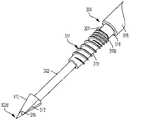
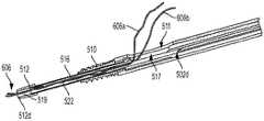
図1〜図8Hは、細長いシャフト102、内部を通じて細長いシャフト102を受容するドライバ又はドライバ装置104、下記に述べるようにループ108を形成する捕捉縫合糸106、及び縫合糸アンカー110を含む外科用システム100の一実施形態を示している。システム100は、埋め込み型であり得る拡張器機構112も含む。 1-8H illustrate a surgical system that includes an
システム100の構成要素は、様々な構成を有することができる。図2及び図3に示されるように、縫合糸アンカー110を骨に打ち込むように構成されたドライバ装置104は、近位ハンドル114、及び近位ハンドル114から延びるドライバシャフト116を有している。ドライバシャフト116は、様々な方法でハンドル114に連結されてもよく、ハンドル114を通じて延びることができる。図3に示されるように、ドライバシャフト116は、遠位ドライバ部材120の近位側の肩部118、及びドライバシャフト116を通じて延びる管腔122を有している。ドライバシャフト116は、特定の外科手術に適した寸法を有することができる。例えばドライバシャフトは、約1mm〜約20mmの範囲の直径、及び約10mm〜約0.5mの範囲の長さを有することができる。同様に、ドライバ部材120は特定の外科手術に適した寸法を有することができる。例えば、遠位ドライバ部材120は、約0.5mm〜約15mmの範囲の直径、及び約2mm〜約50mmの範囲の長さを有することができる。 The components of
ドライバ装置104の近位ハンドル114は、様々な構成を有することができる。図の実施形態では、管腔122は、ドライバ装置104のドライバシャフト116を通じ、更に近位ハンドル114の長さを通じて延びている。他の実施形態では、ドライバシャフト116は好適な様式で近位ハンドル114に連結されてもよく、近位ハンドル114を通じて延びる管腔をドライバシャフト116を通じて延びる管腔と連通させることができる。 The
ドライバ装置104の近位ハンドル114は、ドライバ装置104の使用時のグリップ性を高める表面特徴を有するように構成され得る。例えば、図1及び2に示されるように、近位ハンドル114は、その長さに沿って形成された溝115を有することができる。しかしながら、述べられる実施形態はこの点に関して限定されておらず、近位ハンドル114が任意の好適な特徴を有し得ることを理解されたい。ハンドル114の寸法及び構成は、外科手術中に掴みやすく、効果的であるようなものであり得る。 The
縫合糸アンカー110は、様々な構成を有することができる。図の実施形態では、縫合糸アンカー110は、縫合糸アンカー110を骨と係合するように構成された雄ねじ111が上に形成されている。縫合糸アンカー110は、任意の好適な構成を有することができ、他の骨係合機構を有することができる。縫合糸アンカー110は、それを通じて延びる管腔124を有することができ、管腔124の少なくとも一部の中にドライバ装置104のドライバシャフト116の遠位ドライバ部材120を受容することができる。ドライバシャフト116の管腔122は、それを通じて細長いシャフト102を受容する。図6に示されるような組み立てられた構成では、ドライバ部材120は縫合糸アンカー110を通じて延びており、遠位ドライバ部材120の遠位端120d(ドライバシャフト116の遠位端でもある)は縫合糸アンカー110の遠位端110dの近位に配設されている。しかしながら、他の実施形態では、遠位ドライバ部材120の遠位端120dは、縫合糸アンカー110の遠位端110dと整列するか、又はこれを越えて延びてもよい。図1及び図5〜図7に示されるような組み立てられた構成では、縫合糸アンカー110は、ドライバ装置104のドライバシャフト116に取り付けられており、縫合糸アンカー110は拡張器機構112の近位に拡張器機構112から間隔を置いて位置している。 The
縫合糸アンカー110の寸法は、特定の外科手術の要求条件に応じて異なり得る。例えば、縫合糸アンカーは、約1.5mm〜約15mmの範囲の直径、及び約5mm〜約40mmの範囲の長さを有することができる。縫合糸アンカー110は、任意の好適な材料で作製されていてもよい。例えば、縫合糸アンカー110は、ポリマーで作製されていてもよく、その例としては、ポリエーテルエーテルケトン(PEEK)、ポリ乳酸(PLA)、ポリ(L−乳酸)(PLLA)などが挙げられる。更にポリマーは、放射線透過性及び/又は生体吸収性又は生体分解性であってもよい。 The dimensions of the
遠位ドライバ部材120は、縫合糸アンカー110と着脱可能に嵌合し、嵌合した縫合糸アンカー110を下記により詳細に述べるように骨内に遠位に打ち込むように構成されている。いくつかの実施形態では、本明細書に例示されるように、遠位ドライバ部材120は、縫合糸アンカー110の対応する雌ドライバ機構内に受容されるように構成された雄機構の形態であってもよい。図の実施形態では、図3に示されるように、雄機構は六角形状であり、縫合糸アンカー110の対応する雌ドライバ機構は、縫合糸アンカー110の管腔124の少なくとも一部内に形成された対応する六角形状の雌ドライバ機構であってもよい。 The
図の実施形態では、図4に示されるように、細長いシャフト102は、中心シャフト部分126、及び中心シャフト部分126の遠位肩部127から遠位に延び、細長いシャフト102の遠位端102で終端する遠位シャフト部分128を有している。他の実施形態では、遠位肩部127は形成されなくてもよいことを理解されたい。やはり図4に示されるように、遠位シャフト部分128は、この例では遠位にテーパ状の遠位錐状先端部分130を有することができる。 In the illustrated embodiment, as shown in FIG. 4, the
中心シャフト部分126及び遠位シャフト部分128の寸法は、特定の外科手術の要求条件に応じて異なり得る。図の実施形態では、細長いシャフト102の中心シャフト部分126は、細長いシャフト102の遠位シャフト部分128の外径よりも大きい外径を有することができる。例えば、少なくともいくつかの実施形態では、中心シャフト部分126は、約10mm〜約300mmの範囲の長さ、及び約1mm〜約15mmの範囲の外径を有することができる。別の例として、少なくともいくつかの実施形態では、遠位シャフト部分128は、約1mm〜約50mmの範囲の長さ、及び約0.5mm〜約20mmの範囲の外径を有することができる。 The dimensions of the
細長いシャフト102は、遠位端102dで終端する遠位シャフト部分128及び細長いシャフト102の中心シャフト部分126の少なくとも一部が遠位ドライバ部材120から遠位に延びるようにしてドライバ装置104内に受容され得る。図の実施形態では、細長いシャフト102は、骨内に挿入されて穴を最初に開けるように構成されている。したがって、他の器具を使用して骨に穴を最初に開ける必要がない。 The
図の実施形態では、細長いシャフト102の中心シャフト部分126は、捕捉縫合糸を定置するように構成された、細長いシャフト102を通じて延びる縫合糸保持機構132を有している。図4に示されるように、縫合糸保持機構132は、細長いシャフト102の中心シャフト部分126の側面を通じて延びる開口部136から延びることができる。縫合糸保持機構132は、中心シャフト部分126内に形成された開口部136の近位に位置する中心シャフト部分136内の終端点まで延びることができる。 In the illustrated embodiment, the
縫合糸保持機構132は、任意の好適な構成を有してもよく、捕捉縫合糸106を定置するように細長いシャフト102内に任意の好適な形で形成することができる。図の実施形態では、図4〜図6に示されるように、縫合糸保持機構132は、細長いシャフト102の長手方向軸Lに沿って又は長手方向軸Lに平行に形成された溝の形態であってもよい。溝は、中心シャフト部分126の外側表面内に形成されてもよい。しかしながら、他の実施形態では、縫合糸保持機構132は、管腔又は他の機構であってもよい。 The
図の実施形態では、外科用システム100は縫合糸アンカー110の遠位に位置する拡張器機構112を有している。細長いシャフト102の遠位シャフト部分128は拡張器機構112を通じて延びるように構成されており(図4では別々に示されている)、細長いシャフト102の遠位端102dが拡張器機構112の遠位端112dから遠位に延びるようになっている。拡張器機構112は、細長いシャフト102の遠位端102dによって最初に形成された骨内の穴の寸法を大きくすることにより、骨内への細長いシャフト102の挿入を促すように構成されている。この例では、拡張器機構112は遠位にテーパ状であり、切頭円錐の形態であるが、他の構成を有することもできる。拡張器機構112は、細長いシャフト102上に圧入するか又は他の形でそれと連結されてもよい(例えば、ねじ接続を介して、又は他の好適な嵌合機構を介して)。拡張器機構112は、図の例のように表面特徴を有さなくてもよい。しかしながら、いくつかの実施形態では、拡張器機構112は、骨との係合を促す1つ又は2つ以上の表面特徴を有することができる。拡張器機構112は、任意の好適な寸法を有することができる。例えば、少なくともいくつかの実施形態では、拡張器機構112は、約12mm以下の外径、及び約15mm以下の長さを有することができる。 In the illustrated embodiment, the
いくつかの実施形態では、拡張器機構112は、埋め込み型であってもよく、非金属材料で作製されていてもよい。これは、拡張器機構112の性質が、システム100のイメージングと干渉しないようなものとなることから有用であり得る。更に、拡張器機構112は骨の穴の形成を助けるうえで充分な固さを有する一方で生体吸収性及び/又は生体分解性であり得る。しかしながら、他の実施形態では、拡張器機構112は、金属で作製されていてもよい。 In some embodiments, the
図の実施形態では、軟組織(例えば、断裂靱帯、グラフ外側表面組織など)を、1つ又は2つ以上の保持縫合糸及び縫合糸アンカーを使用して付属する骨に付着させることができる。保持縫合糸は、下記により詳細に述べるように外科用システムに連結された捕捉縫合糸によって細長いシャフトの中心シャフト部分に連結され得る。 In the illustrated embodiment, soft tissue (eg, a torn ligament, graph outer surface tissue, etc.) can be attached to the attached bone using one or more retention sutures and suture anchors. The retention suture can be coupled to the central shaft portion of the elongate shaft by a capture suture coupled to the surgical system as described in more detail below.
図1及び図7に示されるように、外科用システム100に含まれる捕捉縫合糸106は、細長いシャフト102の中心シャフト部分126の縫合糸保持機構132に沿って延び、開口部136から出ており、捕捉縫合糸126の終端部分138a、138bが、ドライバ装置104内のより近位側の点まで延びている。捕捉縫合糸106は開口部136を通じて延びるループ108を形成する。捕捉縫合糸106は、細長いシャフト102の縫合糸保持機構132に沿って、縫合糸保持機構132の近位端から開口部136に向かい、再び開口部136から縫合糸保持機構132の近位端に向かって定置されている。下記により詳細に述べるように、ループ108は少なくとも1本の保持縫合糸が通されるように構成される。ループ108のサイズは、特定の外科手術に応じて異なり得る。例えば、いくつかの実施形態では、ループ108は、外科医が手を通すことができるくらいに充分に大きくすることができる。更に、ループ108のサイズは調節可能であり、捕捉縫合糸106の終端部分138a、138bを引っ張ることにより締め付けられる、又は閉じられるように構成されており、それにより、保持縫合糸が細長いシャフト102の中心シャフト部分126の側壁に対して接触させられる。 As shown in FIGS. 1 and 7, the
外科用システム100は、軟組織を骨に付着させるシステム100の機能を補助する他の様々な機構を有することができる。例えば、外科用システム100は、例えば圧入、ねじ連結、又は他の種類の接続によって細長いシャフト102の中心シャフト部分126の近位端又はその近くに取り付けられた近位端機構140を有することができる。図の実施形態では、近位端機構140は、ドライバ装置104の近位ハンドル114の近位に位置付けられている。近位端機構140は、例えば捕捉縫合糸106の終端部分138a、138bと係合するように構成された切欠き部141のような少なくとも1つの保持機構を有することができる。保持機構は、例えば、溝、隆起部、フック、クランプなどの任意の他の好適な形態であり得ることを理解されたい。保持機構141は、下記により詳細に述べるように、捕捉縫合糸106の終端部分138a、138bと係合することで終端部分138a、138bに張力をかけるように構成されている。
図1及び図5〜図7に示される外科用システム100の組み立てられた構成では、細長いシャフト102は、ドライバ装置104内の管腔を通じて、詳細には、近位ハンドル114及びドライバシャフト116を通じて延びる中心管腔122を通じて延びている。遠位端102d及び細長いシャフト102の中心シャフト部分126の一部は、遠位ドライバ部材120から遠位に延びている。捕捉縫合糸106はシャフト102の中心シャフト部分126の縫合糸保持機構132を通り、縫合糸保持機構132の近位端と開口部136との間に延びているため、捕捉縫合糸106の中間部分は開口部136から延びるループ108を形成している。この構成では、終端部分138a、138bは、ドライバ装置104の近位端から延びている。縫合糸アンカー110は、縫合糸アンカー110の近位端が肩部118に当接するようにドライバ部材120上に取り外し可能に取り付け可能である。また、ドライバシャフト116の少なくとも一部は、遠位ドライバ部材120が管腔124の少なくとも一部と嵌合するようにして縫合糸アンカー110内の管腔124内に延びている。更に、近位端機構140は近位ハンドル114の近位端114pの近位に位置している。細長いシャフト102、ドライバ装置104、縫合糸アンカー110、及び拡張器機構112は、これらの構成要素の長手方向軸が一致するようにして同軸上に整列されている。組み立てられた構成では、システム100は、細長いシャフト102を受容したドライバ装置104と、ドライバシャフト116の遠位ドライバ部材120上に予め装填された縫合糸アンカー110とを含むことができる。しかしながら、いくつかの実施形態では、ドライバ装置104はアセンブリの一部でなくともよく、様々な装置ドライバを外科手術に先立ってシステムの他の構成要素に別々に連結することができる。 In the assembled configuration of the
外科用システム100、又は述べられる方法に基づく同様のシステムを使用して骨への軟組織の再付着又は骨へのグラフト組織の付着を行う外科的修復方法を行うことができる。例えば、システムは、回旋筋腱板修復手術において骨(例えば上腕骨頭)への腱(例えば棘上筋腱)の再付着に使用することができる。述べられる方法は、他の肩修復手術、並びに膝、及び付属する骨への軟組織の付着を必要とする他の関節修復手術でも使用することができる。
図の実施形態に基づく外科的修復方法は、細長いシャフトの遠位端を骨内に挿入することを含む。一実施形態では、シャフトは、埋め込み型カニューレ状拡張器機構、及び拡張器機構の近位に位置し、拡張器機構から少なくとも最初、離間された縫合糸アンカーを通じて延びる。細長いシャフトは、それを通じて延びる管腔を通じて延びる捕捉縫合糸であって、シャフトの側面を通じて延びるとともに拡張器機構の近位に配設された開口部で出る捕捉縫合糸を有し、この捕捉縫合糸は、開口部及びシャフトのより近位の位置まで延びる捕捉縫合糸の終端部分を通じて延びるループを形成する。拡張器機構を有する細長いシャフトの遠位端は、手術の完了時に縫合糸アンカーを完全に定置するのに充分な深さに達するまで骨内に挿入することができる。 The surgical repair method according to the illustrated embodiment includes inserting the distal end of an elongate shaft into the bone. In one embodiment, the shaft extends through the implantable cannulated dilator mechanism and a suture anchor located proximally of the dilator mechanism and spaced at least initially from the dilator mechanism. The elongate shaft has a capture suture extending through a lumen extending therethrough and extending through the side of the shaft and exiting at an opening disposed proximal to the dilator mechanism, the capture suture Forms a loop extending through the opening and the terminal portion of the capture suture extending to a more proximal position of the shaft. The distal end of the elongate shaft with the dilator mechanism can be inserted into the bone until it reaches a depth sufficient to fully deploy the suture anchor at the completion of the surgery.
本方法は、組織に連結された少なくとも1本の保持縫合糸を捕捉縫合糸のループに通すことと、捕捉縫合糸の終端部分に張力を加えることによって捕捉縫合糸のループを保持縫合糸上に閉じることと、も含み、これにより、捕捉縫合糸が保持縫合糸をシャフトの側壁により近づける。これにより、保持縫合糸は、縫合糸アンカーが続いて保持縫合糸と係合して保持縫合糸を(ひいては保持縫合糸に連結された組織を)骨に固定することができるような様式で細長いシャフトに対して保持される。 The method includes passing at least one retention suture coupled to tissue through the capture suture loop and applying tension to the end portion of the capture suture to place the capture suture loop over the retention suture. Closing, so that the capture suture brings the retaining suture closer to the side wall of the shaft. This allows the retention suture to be elongated in such a manner that the suture anchor can subsequently engage the retention suture to secure the retention suture (and thus the tissue coupled to the retention suture) to the bone. Held against the shaft.
いくつかの実施形態では、保持縫合糸は捕捉縫合糸に通され、捕捉縫合糸のループが閉じられるか又は締めつけられた後、細長いシャフトの遠位端が骨内に挿入される。かかる実施形態では、細長いシャフトは、捕捉縫合糸に張力をかけて細長いシャフトに対して保持縫合糸を維持しながら骨内に挿入される。 In some embodiments, the retention suture is passed through the capture suture and the distal end of the elongate shaft is inserted into the bone after the capture suture loop is closed or tightened. In such embodiments, the elongate shaft is inserted into the bone while tensioning the capture suture and maintaining the retaining suture against the elongate shaft.
保持縫合糸が、骨内にシャフトが挿入される前又は後のいずれで捕捉縫合糸のループに連結され、ループと係合するかにかかわらず、本外科的方法は、縫合糸アンカーを遠位機構に向かって遠位に、かつ骨内に打ち込み、それにより、保持縫合糸を前記骨と縫合糸アンカーの外側表面との間に固定することを更に含む。 Regardless of whether the retaining suture is connected to and engages the capture suture loop either before or after the shaft is inserted into the bone, the surgical method distally moves the suture anchor. It further includes driving distally towards the mechanism and into the bone, thereby securing the retaining suture between the bone and the outer surface of the suture anchor.
図8A〜図8Jは、述べられる実施形態に基づく外科的修復方法を示したものである。例として、図1〜図7に示される外科用システム100を使用した外科的修復方法が示されている。しかしながら、外科的修復方法は、1つ又は2つ以上の構成要素が外科用システム100に含まれるものと異なり得る外科用システムを含む、他の外科用システムを用いて行うこともできることを理解されたい。 8A-8J illustrate a surgical repair method according to the described embodiment. As an example, a surgical repair method using the
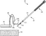
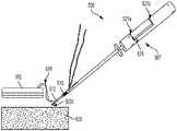
図8Aは、骨200及び外科用システム100を使用して骨200に再付着される軟組織202(例えば腱)を概略的に示している。外科用システム100の細長いシャフト102は、それを通じて延びる捕捉縫合糸106を有しており、開口部136を通じて延びるループ108を形成している。少なくとも1本の保持縫合糸204が、組織202に通されるか又は組織202の周囲に巻き付けられることなどによって組織202に連結されている。図8Aに示されるように、保持縫合糸204の終端部分206a、206bは、矢印207a、207bによって概略的に示されるようにループ108に通されている。あくまで例として1本の保持縫合糸204が示されているが、複数の捕捉縫合糸を用いて組織202を骨200に連結することができることを理解されたい。捕捉縫合糸ループ108は比較的大きなサイズであり、また調節可能であるため、複数の捕捉縫合糸を使用して軟組織を骨に連結することができる。 FIG. 8A schematically illustrates soft tissue 202 (eg, a tendon) being reattached to
保持縫合糸204をループ108に通した後、捕捉縫合糸を、その終端部分138a、138bに張力を加えることによって閉じることができる。図8Bに示されるように、外科用システム100は、シャフト102の近位端又はその近くに取り外し不能又は取り外し可能に配設された近位端機構140を含み、近位端機構140はドライバ装置のハンドル114の近位に配設されている。近位端機構140は、捕捉縫合糸の終端部分と係合するように構成された切欠き部141又は他の保持機構(例えば溝)が上に形成されている。このため、図8Bに示されるように、終端部分138a、138bは、切欠き部141と係合することによって近位端機構140の周囲に巻き付けられ、これにより、捕捉ループ108を閉じるために捕捉縫合糸108の終端部分を細長いシャフト102から離れる方向(矢印209により概略的に示される)に引っ張る間、捕捉縫合糸108の終端部分にかかる張力を維持する助けとなる。このようにして、保持縫合糸204は、下記に述べるように保持縫合糸204が縫合糸アンカー110と骨との間に押し込まれるまでの間、細長いシャフト102に対して保持される。図の方法の利点としては、結び目を作ることなく、軟組織を骨に固定的に再付着するために修復法を行うことができる容易性が挙げられる。 After passing the
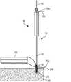
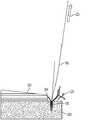
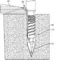
捕捉ループ106の終端部分138a、138bにかかる張力を維持した状態で、図8Bに示されるように、細長いシャフト102の遠位端102dを骨200内に挿入して骨200の所望の位置において骨200に穴を最初に開ける。図の実施形態では、細長いシャフト102は、穴を最初に開けるように構成された自己穿孔型のシャフトであり、他の器具を必要としない。図8Bは、骨穴が最初に開けられた後、マレット、ハンマー、又は他の器具などの好適な器具210を使用して細長いシャフト102が骨200内に遠位に更に打ち込まれることも示している。この例では、矢印211により概略的に示されるように、器具210を使用して細長いシャフト102の近位端102pに力を加えることによって細長いシャフト102の遠位端102dを骨200内に打ち込んで穴212を形成することができる。図8C及び図8Dに示されるように、細長いシャフト102の遠位端102dを骨200内に打ち込むことで、拡張器機構112が連結された細長いシャフト102の遠位シャフト部分128を骨200内の穴212内に挿入することができる。細長いシャフト102の中心シャフト部分126の一部も穴212内に挿入されるのに対して、縫合糸アンカー110は骨穴212に対して所望の位置に位置付けられる。図の実施形態では、図8Dに示されるように、縫合糸アンカー110は、骨内に打ち込まれる前に骨穴212のすぐ近位に配設される。他の実施形態では、縫合糸アンカー110は穴212に対して異なる位置に配設されてもよく、例えば、縫合糸アンカー110は骨穴内に少なくとも部分的に挿入されてもよい。穴212の直径は、穴212がその中に縫合糸アンカー110をぴったりと収めることができるように形成することができる。 With the tension on the
図8Dに示されるように、保持縫合糸204の終端部分206a、206bは骨穴112の外部に配設され、図8Dに矢印215a、215bにより概略的に示されるように、終端部分206a、206bにかけられる張力によって縫合糸204が骨穴112内に緊張状態で位置付けられ、一時的に保持される。保持縫合糸204の終端部分206a、206bに加えられる張力によって、組織202を骨穴112に対して望みどおりに位置付けることができる。例えば図の実施形態では、組織202は、図8Cに示される組織202よりも骨穴212の近くに組織202が位置する図8Dに示されるように、穴212のより近くに移動することができる。 As shown in FIG. 8D, the
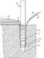
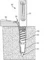
拡張器機構112を有する細長いシャフト102が骨200内に挿入されて所望の位置に骨穴212が形成された時点で、縫合糸アンカー110を拡張器機構112に向かって遠位に、かつ骨穴212内に打ち込むことにより、図8E及び図8Fに示されるように、保持縫合糸204を骨穴212の内側表面と縫合糸アンカー110の外側表面との間に固定することができる。図の実施形態では、遠位ドライバ部材120が縫合糸アンカー110に着脱可能に連結されたドライバ装置104を操作して縫合糸アンカー110を骨穴212内に打ち込む。例えば、ドライバ装置104を図8Eで矢印217により概略的に示されるように回転させることで、ドライバ装置104に連結された縫合糸アンカー110を、縫合糸アンカー110のねじ山111が骨穴212の内壁と係合した状態で骨内へと遠位に前進させることができる。ドライバ装置104が回転させられる際、ドライバ装置104の管腔122を通じて延びる細長いシャフト102は静止状態に保たれる。したがって、図8Eに示されるように、ドライバ装置104が遠位に打ち込まれた後、ドライバ装置104の近位ハンドル114は、細長いシャフト102の近位端に連結された近位端機構140からオフセットし、かつより遠位に配設される。ドライバ装置104が回転し、それにより、縫合糸アンカー110を拡張器機構112に向かって遠位に、かつ骨200内に移動させることにより、保持縫合糸204が縫合糸アンカー110の側壁と骨穴212との間に保持される。 When the
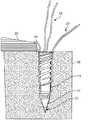
縫合糸アンカー110が骨200の穴212内に打ち込まれた時点で、図8Gに矢印219により示されるように細長いシャフト102を拡張器機構112から分離することができ、ドライバ装置104を縫合糸アンカー110から分離することができる。いくつかの実施形態では、細長いシャフト102はドライバ装置104に連結されなくてもよく、ドライバ装置104が縫合糸アンカー110から分離される前に細長いシャフト102を拡張器機構112から分離してドライバ装置104の管腔122から取り除かれ得る。他の実施形態では、細長いシャフト102とドライバ装置104とは互いに連結されてもよく、これらを拡張器機構112及び縫合糸アンカー110からほぼ同時に分離することができる。細長いシャフト102及びドライバ装置104が取り除かれる様式にかかわらず、拡張器機構112及び縫合糸アンカー110は図8G及び図8Hに示されるように、骨穴212内に埋め込まれたままとなる。図8Gに示されるように、縫合糸206に張力をかける助けとなる近位端機構140に連結された捕捉縫合糸106の終端部分138a、138bを、近位端機構140に巻き付いた状態から解くことによって近位端機構140から分離することができる。 Once the
図8Hは、骨穴212内に埋め込まれた拡張器機構112及び縫合糸アンカー110を示している。細長いシャフト102及びドライバ装置104が取り除かれた後、図8Hに示されるように捕捉縫合糸106は縫合糸アンカー110に付属したままである。いくつかの実施形態では、縫合糸アンカー110が骨200内に打ち込まれた後、細長いシャフト102及びドライバ装置104が取り除かれる前に、それと同時に、又はその後に、図9Aに矢印223によって概略的に示されるように、捕捉縫合糸106が取り除かれ得る。保持縫合糸204の終端部分206a、206bは、例えばハサミ225を使用することによって切断することができる。その結果、図9Bに示されるように、捕捉縫合糸106が連結されていない縫合糸アンカー110が骨200に保持縫合糸204を固定し、それにより、組織202が骨200に固定される。保持縫合糸204の終端部分206a、206bは、やはり図9Bに示されるように切断することができる。 FIG. 8H shows the
上記に述べた各実施形態では、外科用システムの細長いシャフトは、保持縫合糸が捕捉縫合糸ループに連結された後、かつ保持縫合糸をシャフトに対して保持するためにループが閉じられた後に、骨内に挿入される。しかしながら他の実施形態では、捕捉縫合糸が連結された細長いシャフトを骨内に最初に挿入することができ、次いで1本又は2本以上の保持縫合糸が捕捉縫合糸ループに通され、ループが締め付けられるか又は閉じられ、それにより、保持縫合糸を細長いシャフトの方向に、かつ細長いシャフトに対して動かすことができる。上記のアプローチのいずれが用いられるかによらず、外科用システムの細長いシャフトが骨穴を形成するために骨内に打ち込まれ、捕捉縫合糸ループがループに通された保持縫合糸上に閉じられた時点で、縫合糸アンカーが遠位に骨内に打ち込まれる。縫合糸アンカーが骨穴内に適切に位置付けられると、縫合糸アンカーは、保持縫合糸を骨内に固定し、それにより保持縫合糸に連結された組織を骨に固定する。 In each of the embodiments described above, the elongate shaft of the surgical system is configured such that the retention suture is coupled to the capture suture loop and after the loop is closed to retain the retention suture against the shaft. Inserted into the bone. However, in other embodiments, an elongate shaft coupled with a capture suture can be first inserted into the bone, and then one or more retaining sutures are passed through the capture suture loop, the loop being It can be tightened or closed so that the retaining suture can be moved in the direction of the elongated shaft and relative to the elongated shaft. Regardless of which of the above approaches is used, the elongate shaft of the surgical system is driven into the bone to form a bone hole and the capture suture loop is closed over the retaining suture threaded through the loop. At that point, the suture anchor is driven distally into the bone. When the suture anchor is properly positioned within the bone hole, the suture anchor secures the retention suture within the bone, thereby securing the tissue coupled to the retention suture to the bone.
いくつかの実施形態では、外科用システムは、ドライバ装置又はドライバ、細長いシャフト、雄ねじが上に形成された縫合糸アンカー、及び縫合糸アンカーの遠位に位置する拡張器機構を有することができる。ドライバは、近位ハンドルと、近位ハンドルから延びるドライバシャフトとを有することができ、ドライバシャフトは遠位ドライバ機構及びドライバシャフトを通じて延びる管腔を有し、ドライバはその側面を通じて延びる開口部を有する。細長いシャフトは、細長いシャフトの遠位部分が前記遠位ドライバ機構から遠位に延びるようにしてドライバの管腔内に受容可能であり、細長いシャフトの中心シャフト部分は、ドライバの開口部と連通する、中心シャフト部分を通じて延びる縫合糸保持機構を有する。縫合糸アンカーは、中心シャフト部分をその内部に取り外し可能に受容する、縫合糸アンカーを通じて延びる管腔を有してもよく、遠位ドライバ機構が縫合糸アンカーに動作可能に連結される。遠位の拡張器機構は、それを通じて細長いシャフトの遠位部分の少なくとも一部が延びてもよく、細長いシャフトの遠位先端部の少なくとも一部が拡張器機構の遠位端から遠位に延びる。 In some embodiments, the surgical system can have a driver device or driver, an elongate shaft, a suture anchor with an external thread formed thereon, and a dilator mechanism located distal to the suture anchor. The driver can have a proximal handle and a driver shaft extending from the proximal handle, the driver shaft having a distal driver mechanism and a lumen extending through the driver shaft, and the driver having an opening extending through a side thereof. . An elongate shaft is receivable within the driver lumen such that a distal portion of the elongate shaft extends distally from the distal driver mechanism, and the central shaft portion of the elongate shaft communicates with the driver opening. A suture retaining mechanism extending through the central shaft portion. The suture anchor may have a lumen extending through the suture anchor that removably receives the central shaft portion therein, and a distal driver mechanism is operably coupled to the suture anchor. The distal dilator mechanism may extend through at least a portion of the distal portion of the elongated shaft and at least a portion of the distal tip of the elongated shaft extends distally from the distal end of the dilator mechanism. .
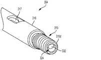
図10〜図15Iは、細長いシャフト302、内部を通じて細長いシャフト302を受容するドライバ304、縫合糸アンカー310、及び埋め込み型であり得る拡張器機構312を含む外科用システム300の別の実施形態を示している。図の実施形態では、ドライバ304は近位ハンドル314を有することができる。細長いシャフト302もまた、その近位端に連結されたハンドル340を有している。図10に示されるように、細長いシャフト302のハンドル340は、ドライバ304の近位ハンドル314の近位に配設されている。細長いシャフト302のハンドル340と、ドライバ304の近位ハンドル314とは、下記により詳細に述べるように、独立して移動可能であり得る。 10-15I illustrate another embodiment of a
システム300の構成要素は、様々な構成を有することができる。図10に示されるように、縫合糸アンカー310を骨に打ち込むように構成されたドライバ装置304は、近位ハンドル314、及び近位ハンドル314から延びるドライバシャフト316を有している。ドライバシャフト316は、様々な形でハンドル314に連結され得る。図11に示されるように、ドライバシャフト316は遠位ドライバ部材320の近位に肩部318を有しており、この遠位ドライバ部材320は肩部318から、ドライバ装置304のドライバシャフト316の遠位端でもある遠位ドライバ部材320の遠位端320dまで延びている。遠位ドライバ部材320には、図13及び図14に示されるように縫合糸アンカー310が取り付けられている。図の実施形態では、ドライバシャフト316は、肩部318と遠位ドライバ部材320との間にネック機構321を有しており、ネック機構321は縫合糸アンカー310の近位端310pと当接している。使用時には、ネック機構321は、縫合糸アンカー310を遠位に打ち込む助けとなる。ドライバシャフト316は、肩部318及び/又はネック機構321が含まれない構成を含む、他の好適な構成を有することができることを理解されたい。 The components of
ドライバシャフト316は、図12〜14に示されるようにそれを通じて延びる管腔322を有している。ドライバシャフト316の管腔322は、それを通じて細長いシャフト302を受容する。更に、図の実施形態では、ドライバ装置304のドライバシャフト316は、図10及び図12〜14に示されるようにその側面を通じて延びる開口部317を有している。
ドライバ装置304の近位ハンドル314は、様々な構成を有することができる。図の実施形態では、ドライバ装置304の管腔322は、ドライバシャフト316を通じ、更に近位ハンドル314の長さを通じて延びている。このようにして、ドライバ装置304の管腔322は、それを通じて細長いシャフト302を受容する。ドライバシャフト316は、近位ハンドル314を回転させるとドライバシャフト316が回転するように好適な様式で近位ハンドル314に連結されている。ドライバ装置304の近位ハンドル314は、ドライバ装置304の使用時のグリップ性を高める表面特徴を有するように構成され得る。例えば、図10に示されるように、近位ハンドル314は、その長さに沿って形成された1つ又は2つ以上の溝315を有することができる。しかしながら、述べられる実施形態はこの点に関して限定されておらず、近位ハンドル314が任意の好適な特徴を有し得ることを理解されたい。 The
縫合糸アンカー310は、様々な構成を有することができる。図の実施形態では、縫合糸アンカー310は、縫合糸アンカー310を骨と係合するように構成された雄ねじ311が上に形成されている。雄ねじ311は、1つ又は2つ以上のねじ山の形態であってもよい。縫合糸アンカー310は、任意の好適な構成を有することができ、他の骨係合機構を有することができる。図12〜14に示されるように、縫合糸アンカー310はそれを通じて延びる管腔324を有することができ、管腔324の少なくとも一部の中に遠位ドライバ部材320を受容することができる。図13及び14に示されるような組み立てられた構成では、遠位ドライバ部材320は縫合糸アンカー310の管腔324を通じて延びており、遠位ドライバ部材320の遠位端320dは縫合糸アンカー310の遠位端310dの近位に配設されている。しかしながら、他の実施形態では、遠位ドライバ部材320の遠位端320dは、縫合糸アンカー310の遠位端310dと整列するか、又はこれを越えて延びてもよい。 The
ドライバ装置304の遠位ドライバ部材320は、縫合糸アンカー310と着脱可能に嵌合し、それにより、嵌合した縫合糸アンカー310を下記により詳細に述べるように骨内に遠位に打ち込むように構成されている。いくつかの実施形態では、本明細書に例示されるように、遠位ドライバ部材320は、縫合糸アンカー310の管腔を画定する内壁の少なくとも一部に形成された対応する雌ドライバ機構内に受容されるように構成された雄機構の形態であってもよい。 The
図の実施形態では、図12に示されるように、雄機構は六角形状であり、縫合糸アンカー310の対応する雌ドライバ機構は、縫合糸アンカー310の管腔324を画定する内壁の少なくとも一部内に形成された対応する六角形状の雌ドライバ機構であってもよい。図12は、縫合糸アンカー310の管腔324を画定する内壁の少なくとも一部の断面が六角形であることを示している。図の実施形態では、管腔324を画定する内壁の遠位部分319(図13及び14)の内部には、遠位ドライバ部材320と嵌合するように構成された雌機構(例えば六角形の雌機構)が形成されなくてもよい。この実施形態では、ドライバ装置304の遠位ドライバ部材320は縫合糸アンカー310の管腔324を通じて延びており、遠位ドライバ部材320の遠位端320dは縫合糸アンカー310の遠位端310dの近位に配設されている。縫合糸アンカー310の管腔324を画定する内壁の遠位部分319の断面は円形であってもよく、これにより、縫合糸アンカー310の管腔324の遠位端に縫合糸を通すことが容易となる。 In the illustrated embodiment, as shown in FIG. 12, the male mechanism is hexagonal and the corresponding female driver mechanism of the
図の実施形態では、図13及び14に示されるように、細長いシャフト302は、中心シャフト部分326、及び遠位肩部327から遠位に延び、細長いシャフト302の遠位端302で終端する遠位シャフト部分328を有している。しかしながら、他の実施形態では、遠位肩部327は形成されなくてもよいことを理解されたい。遠位シャフト部分328は、遠位にテーパ状の遠位錐状先端部分330を有している。図の実施形態では、遠位シャフト部分328は、中心シャフト部分326の外径よりも小さい外径を有することができる。 In the illustrated embodiment, the
組み立てられた構成では、細長いシャフト302は、細長いシャフト302の遠位シャフト部分328及び細長いシャフト302の中心シャフト部分326の少なくとも一部が遠位ドライバ部材320から遠位に延びるようにしてドライバ装置304の管腔322内に受容され得る。細長いシャフト302は、ドライバ装置304の管腔322から取り外し可能であり得る。図の実施形態では、細長いシャフト302の遠位端302dは、骨内に挿入されて骨に穴を最初に開けるように構成されている。したがって、他の器具を使用して骨に穴を最初に開ける必要がない。 In the assembled configuration, the
図の実施形態では、図12〜図14に示されるように、細長いシャフト302の中心シャフト部分326は、少なくとも1本の縫合糸を定置するように構成された、細長いシャフト302を通じて延びる縫合糸保持機構332を有している。図13及び14に示されるように、縫合糸保持機構332は、中心シャフト部分326の遠位端326dから延びることができる。この例では、中心シャフト部分326の遠位端326dは中心シャフト部分326の遠位肩部327と一致しているが、中心シャフト部分326はこのような遠位肩部を有さなくてもよい。縫合糸保持機構332は、中心シャフト部分336内の終端点まで延びてもよく、これにより縫合糸保持機構332はドライバ装置304の側面を通じて延びる開口部317と連通する。図の実施形態では、図13及び図14に示されるように、縫合糸保持機構332は、ドライバ装置304の開口部317の近位端317pで概ね終端している。しかしながら、縫合糸保持機構332は、開口部317の近位端317pの遠位側又は近位側で終端してもよい。 In the illustrated embodiment, as shown in FIGS. 12-14, the
細長いシャフト302の中心シャフト部分326の縫合糸保持機構332は、任意の好適な構成を有してもよく、少なくとも1本の縫合糸を細長いシャフト302に沿って定置するように細長いシャフト302内に任意の好適な形で形成されてもよい。図の実施形態では、縫合糸保持機構332は、中心シャフト部分326の外側表面に細長いシャフト302の長手方向軸に沿って又は長手方向軸に平行に形成された溝の形態であってもよい。しかしながら、他の実施形態では、縫合糸保持機構332は、管腔又は他の機構であってもよい。 The
図の実施形態では、外科用システム300は縫合糸アンカー300の遠位に位置する拡張器機構312を有している。細長いシャフト302の遠位シャフト部分328は拡張器機構312を通じて延びるように構成されており、細長いシャフト302の遠位端302dが拡張器機構312から遠位に延びている。拡張器機構312は、穴が最初に開けられた時点で例えば細長いシャフト302の遠位端302dによって骨内の穴を拡げることにより、骨内への細長いシャフト302の挿入を促すように構成されている。拡張器機構312は遠位にテーパ状である。図11に示されるように、拡張器機構312は、2つ又は3つ以上の三角形の面313を有する切頭角錐の形状の形態であってもよい。面313はほぼ平坦としてもよく、又は他の形で構成してもよい。図の実施形態では、拡張器機構312は3つの面313を有しており、面313のそれぞれは面の遠位端に溝315を有している。このような拡張器機構312の形状は、骨内への拡張器機構312の挿入を促すことができる。拡張器機構312は、2つ又は3つ以上の面を有することができることを理解されたい。また、他の実施形態では、拡張器機構312は切頭円錐の形態であってもよいが、拡張器機構312は他の好適な構成を有してもよい。 In the illustrated embodiment, the
拡張器機構312は、細長いシャフト302上に圧入するか、又は他の形で着脱可能に連結することができる。拡張器機構312は、図の実施形態のように表面特徴を有さなくてもよい。しかしながら、いくつかの実施形態では、拡張器機構312は、骨との係合を促す1つ又は2つ以上の表面特徴を有することができる。拡張器機構312は、任意の好適な寸法を有することができる。更に、いくつかの実施形態では、拡張器機構312は、埋め込み型であってもよく、非金属材料で作製されていてもよい。これは、拡張器機構312の性質が、システム300のイメージングと干渉しないようなものとなることから有用であり得る。更に、拡張器機構312は骨の穴の形成を助けるうえで充分な固さを有する一方で生体吸収性及び/又は生体分解性であり得る。しかしながら、他の実施形態では、拡張器機構312は、金属で作製されていてもよい。 The
図の実施形態では、図の実施形態では、図14に示されるように、外科用システム300には、組織を骨に付着させるために用いられる少なくとも1本の縫合糸406を付属させることができる。縫合糸406は外科用システム300によって保持することができ、組織に連結することができる縫合糸406の終端部分406a、406bが、細長いシャフト302の中心シャフト部分326の縫合糸保持機構332に沿って、更にドライバ装置304の側面を通じて延びる開口部317を通じて縫合糸アンカー310の管腔324に通される。図14に示されるように、縫合糸406の終端部分406a、406bは開口部317から延出している。 In the illustrated embodiment, in the illustrated embodiment, as shown in FIG. 14, the
図15A〜図15Jは、軟組織402(例えば腱)を骨400に付着させるための外科的修復方法で使用される外科用システム300を示したものである。述べられる実施形態に基づく外科的修復方法は、1つ又は2つ以上の構成要素が外科用システム300に含まれるものと異なり得る外科用システムを含む、他の外科用システムを用いて行うこともできることを理解されたい。 15A-15J illustrate a
図15Aは、縫合糸406の終端部分406a、406bがシステム300に連結されることを概略的に示している(矢印407)。上記に述べたように、縫合糸406の終端部分406a、406bは、図14に示されるように、細長いシャフト302の中心シャフト部分326の縫合糸保持機構332に沿って、更にドライバ装置304の側面を通じて延びる開口部317を通じて縫合糸アンカー310の管腔324に通すことができる。図15Aは、縫合糸406が組織402に連結され得ることを示している。例えば、縫合糸406は、縫合糸406の終端部分406a、406bがシステム300と自由に係合できるように組織402に通すか又は他の形で組織402に連結することができる。 FIG. 15A schematically illustrates that the
図15Bは、縫合糸406が装填された外科用システム300を示している。矢印409により示されるように、縫合糸406に張力が加えられ得る。捕捉縫合糸406の終端部分406a、406bにかかる張力を維持した状態で、図15Cに示されるように、細長いシャフト302の遠位端302dを骨400内に挿入して骨400の所望の位置において骨400に穴を最初に開ける。図の実施形態では、細長いシャフト302は、穴を最初に開けるように構成された自己穿孔型のシャフトであり、他の器具を必要としない。図15Cは、骨に穴が最初に開けられた後、マレット、ハンマー、又は他の器具などの好適な器具410を使用して細長いシャフト302を骨400内に遠位に更に打ち込むことも示している。この例では、矢印411により示されるように、器具410を使用して細長いシャフト302の近位に連結された近位ハンドル340の近位端340pに力を加え、それにより細長いシャフト302の遠位端302dを骨400内に更に打ち込むことができる。 FIG. 15B shows
細長いシャフト302が骨400内に遠位に打ち込まれるにつれて、拡張器機構312が穴を拡げる。細長いシャフト302の遠位端302dが骨400内に挿入される際、図15Dに矢印413によって示されるように縫合糸406の終端部分406a、406bにかかる張力を維持することができる。図15D及び15Eに示されるように、細長いシャフト302の遠位端302dを骨400内に打ち込むことで、拡張器機構312が連結された細長いシャフト302の遠位シャフト部分328を骨400内の穴412内に挿入することができる。細長いシャフト302の中心シャフト部分326の一部も穴412内に挿入されるのに対して、縫合糸アンカー410は骨穴412に対して所望の位置に位置付けられる。図の実施形態では、図15Eに示されるように、縫合糸アンカー310は、骨内に打ち込まれる前に骨穴412のすぐ近位に位置付けられる。他の実施形態では、縫合糸アンカー310は、骨穴内に少なくとも部分的に挿入することができる。 As the
拡張器機構312を有する細長いシャフト302の遠位端302dが骨400内に所望の深さまで打ち込まれた時点で、縫合糸アンカー310を拡張器機構312に向かって遠位に、かつ骨穴412内に打ち込むことができる。図の実施形態では、遠位ドライバ部材320が縫合糸アンカー310に着脱可能に連結されたドライバ装置304を作動させて縫合糸アンカー310を遠位に骨穴412内に打ち込む。図15Fに示されるように、ドライバ装置304を、例えば矢印415により示されるようにドライバ装置304の近位ハンドル314を回転させることなどによって回転させることができる。図15F及び図15Gに示されるように、この回転によって、縫合糸アンカー310が拡張器機構312に向かって遠位に、かつ骨400内に前進する。縫合糸アンカー310のねじ山311が骨400と係合する。ドライバ装置304が回転させられる際、ドライバ装置304の管腔322及び拡張器機構312を通じて延びる細長いシャフト302は静止状態に保たれる。例えば、図15Hは、装置ドライバ304が遠位に打ち込まれた後、ドライバ装置304の近位ハンドル314が、細長いシャフト302の近位ハンドル340からオフセットし、装置ドライバ304が遠位に打ち込まれる前(例えば図15F)よりも細長いシャフト302の近位ハンドル340に対してより遠位に配設されることを示している。装置ドライバ304を回転させることにより縫合糸アンカー310を拡張器機構312に向かって遠位に、かつ骨400内に移動させると、縫合糸406が骨穴412と縫合糸アンカー310の外側表面との間に固定される。 When the
縫合糸アンカー310が骨400の穴412内に打ち込まれた時点で、図15Hに矢印417により示されるように細長いシャフト302を拡張器機構312から分離することができ、ドライバ装置304を縫合糸アンカー310から分離することができる。いくつかの実施形態では、細長いシャフト302はドライバ装置304に連結されなくてもよく、ドライバ装置304が縫合糸アンカー310から分離される前に細長いシャフト302が拡張器機構312から分離されて、ドライバ装置304の管腔322から取り除かれ得る。他の実施形態では、細長いシャフト302とドライバ装置304とは互いに連結されてもよく、これらを拡張器機構312及び縫合糸アンカー310からほぼ同時に分離することができる。細長いシャフト302及びドライバ装置304が取り除かれる様式にかかわらず、拡張器機構312及び縫合糸406が連結された縫合糸アンカー310は、図15Iに示されるように骨穴412内に埋め込まれたままとなり、それにより組織402を骨400に付着させる。必要に応じて、縫合糸406の終端部分406a、406bを好適な切断器具を用いて切断してもよく、図15Iは、例として切断された終端部分406a、406bを示している。また、いくつかの実施形態では、縫合糸406の終端部分406a、406bが組織402に通されてもよく、又は終端部分406a、406bが別の縫合糸アンカーに連結されてもよい。 When the
いくつかの実施形態では、外科用システムは、プッシャ装置、ドライバ装置又はドライバ、細長いシャフト、縫合糸アンカー、及び埋め込み型拡張器機構を含む。プッシャ装置は、近位ハンドルと、近位ハンドルから延びるシャフトとを有し、このシャフトはそれを通じて延びる第1の管腔を有し、プッシャ装置はその側面を通じて延びる第1の開口部を有する。ドライバは、近位ハンドルと、近位ハンドルから延び、内部を通じて延びる第2の管腔を有するシャフトとを有し、ドライバのシャフトは、プッシャ装置の第1の管腔を少なくとも部分的に通じて延び、ドライバはその側面を通じて延びる第2の開口部を有し、第2の開口部は第1の開口部と連通する。細長いシャフトは第2の管腔内に近位に後退可能に配設されてもよく、これにより、細長いシャフトは後退構成と前進構成との間を移動することができる。細長いシャフトが後退構成にある場合、少なくとも1本の縫合糸が外科用システムに連結され得る。雄ねじが上に形成された縫合糸アンカーは、ドライバのドライバシャフトの遠位ドライバ部材を内部に取り外し可能に受容する、縫合糸アンカーを通じて延びる第3の管腔を有する。拡張器機構は、縫合糸アンカーの遠位の遠位ドライバ部材上に取り外し可能に配設され得る。 In some embodiments, the surgical system includes a pusher device, a driver device or driver, an elongate shaft, a suture anchor, and an implantable dilator mechanism. The pusher device has a proximal handle and a shaft extending from the proximal handle, the shaft having a first lumen extending therethrough, and the pusher device having a first opening extending through a side thereof. The driver has a proximal handle and a shaft having a second lumen extending from and extending through the proximal handle, the shaft of the driver at least partially through the first lumen of the pusher device. The driver has a second opening extending through the side thereof, the second opening being in communication with the first opening. The elongate shaft may be retreatably disposed proximally within the second lumen so that the elongate shaft can move between a retracted configuration and an advanced configuration. When the elongate shaft is in the retracted configuration, at least one suture can be coupled to the surgical system. A suture anchor having a male thread formed thereon has a third lumen extending through the suture anchor that removably receives a distal driver member of the driver shaft of the driver therein. The dilator mechanism may be removably disposed on the distal driver member distal to the suture anchor.
図16〜図20Iは、オーバーチューブ又はプッシャ装置501、細長いシャフト502、その内部を少なくとも部分的に通じて細長いシャフト502を受容するドライバ装置又はドライバ504、縫合糸アンカー510、及び埋め込み型であり得る拡張器機構512を含む外科用システム500の別の実施形態を示したものである。図の実施形態では、ドライバ装置504は近位ハンドル514を有することができる。細長いシャフト501もまた、その近位端に連結されたハンドル503を有することができる。図16に示されるように、ドライバ装置504の近位ハンドル514は、プッシャ装置501のハンドル503の近位に配設されている。図の実施形態では、細長いシャフト502は、ドライバ装置504の近位ハンドル514内に配設された後退機構507に連結されており、後退機構507は、下記により詳細に述べるように、細長いシャフト502を後退構成と伸長構成との間を移動させように作動するように構成されている。 16-20I can be an overtube or
システム500の構成要素は、様々な構成を有することができる。プッシャ装置501は、下記に述べるように縫合糸アンカー510に力を加えるように構成されており、様々な構成を有することができる。図16、図17A、及び図17Bに示されるように、プッシャ装置501は、プッシャ装置501の近位ハンドル503から遠位に延びるシャフト505を有している。プッシャ装置501のシャフト505は、内部を通じてドライバ504を受容する、シャフト505を通じて延びる管腔509を有している。プッシャ装置501は、その側面を通じて延びる開口部511を有している。 The components of
ドライバ504は、縫合糸アンカー510を骨内に打ち込むように構成されており、やはり様々な構成を有することができる。図の実施形態では、ドライバ504は、ドライバ504の近位ハンドル516から遠位に延び、かつドライバ504を通じて延びる管腔522を有するドライバシャフト516を有している。図17A及び図17Bに示されるように、ドライバシャフト516は遠位ドライバ部材520を有しており、この遠位ドライバ部材520は、ドライバシャフト516内のある点又は機構から、ドライバ504のドライバシャフト516の遠位端でもある遠位ドライバ部材520の遠位端520dまで延びている。例えば、図17A及び図17Bに示されるように、ドライバシャフト516は遠位ドライバ部材520の近位に肩部518を有することができ、遠位ドライバ部材520は肩部518から遠位ドライバ部材520の遠位端520dまで延びている。図の実施形態では、遠位ドライバ部材520は、図17A及び図17Bに示されるように、拡張器機構512を通じ、更に縫合糸アンカー510を通じて延びるように構成されている。
図の実施形態では、ドライバ504のドライバシャフト516は、プッシャ装置501の管腔509を少なくとも部分的に通じて延びている。更に、ドライバ504は、そのドライバシャフト516にドライバシャフト516の側面を通じて延びる開口部517を有している。組み立てられた構成では、図16、図17A、図17B、及び図18に示されるように、ドライバシャフト516を通じて延びる開口部517は、プッシャ装置501を通じて延びる開口部511と連通する。 In the illustrated embodiment, the
ドライバシャフト516の管腔522は、それを通じて細長いシャフト502を受容するように構成されており、細長いシャフト502は、管腔522内に近位に後退可能に配設されてもよい。図の実施形態では、細長いシャフト502は、図17Aに示される、細長いシャフト502の遠位端502dがドライバシャフト516の開口部517の近位に配設される後退構成と、図17Bに示される、細長いシャフト502の遠位端502dが拡張器機構512の遠位端512dから遠位に延びる前進構成との間を移動するように構成されている。後退構成では、細長いシャフト502は、ドライバシャフト516の壁の遠位端517dと壁の近位端517pとの間に延びる開口部517を画定するドライバシャフト502の壁の少なくとも遠位端517dの近位に配設されてもよい。図17Aに示されるように、細長いシャフト502は、開口部517を画定するドライバシャフト502の壁の近位端517pの近位に配設されてもよい。図の実施形態では、プッシャ装置501の開口部511は、ドライバシャフト516の開口部517の長さとほぼ同じ長さを有することができ、又はプッシャ装置501の開口部511はドライバシャフト516の開口部517の長さよりも大きい長さを有することができる。プッシャ装置501の開口部511及びドライバシャフト516の開口部517の特定のサイズにかかわらず、開口部511、517は、それらの少なくとも一部が整列するように形成されて、それにより、縫合糸がドライバシャフト516の管腔522から開口部511、517の両方に通ることを可能にする。 The
図の実施形態では、細長いシャフト502は、例えば図10〜図15Iの細長いシャフト502の外径よりも小さくなり得る、小径化した外径を有することができる。これにより、細長いシャフト502はドライバシャフト516の管腔522内に収まり、細長いシャフト502内に縫合糸保持機構を形成することなく、1本又は2本以上の縫合糸を細長いシャフト502の少なくとも一部に沿って管腔522に通すことができる。しかしながら、いくつかの実施形態では、溝、通路、又は他の機構の形態の縫合糸保持機構を細長いシャフト502内に形成することができる。 In the illustrated embodiment, the
ドライバ装置504の近位ハンドル514は、様々な構成を有することができる。図の実施形態では、近位ハンドル514は、細長いシャフト502を後退構成と前進構成との間を移動させるように作動するように構成された後退機構507を有している。後退機構507は、様々な構成を有することができる。例えば、図16に示されるように、後退機構507は、通路523を介して連通する第1及び第2の保持スロット521a、521bを有することができ、通路523内で細長いシャフト502に連結されたハンドル又はレバー525は、第1の遠位側スロット521aと近位側スロット521bとの間を移動することができ、それにより、それぞれ、細長いシャフト502を、前進構成と後退構成との間を移動させることができる。レバー525は、ノブ又はグリップ性を高める他の任意の機構を有することができ、任意の好適な様式で細長いシャフト502に動作可能に連結することができる。更に、いくつかの実施形態では、細長いシャフト502とレバー525とを一体形成することもできる。後退機構507はあくまで例として図の実施形態で示したものにすぎず、任意の好適な機構をこれに加えて、又はこれに代えて使用して、細長いシャフト502が前進構成と後退構成との間を移動することを可能にすることができることを理解されたい。 The
細長いシャフト502が図17Aに示されるような後退構成にある場合、細長いシャフト502の遠位端502dは、ドライバシャフト516の開口部517を画定するドライバシャフト516の壁の遠位端517dの近位に配設されてもよい。細長いシャフト502の遠位端502dがプッシャチューブ501及びドライバシャフト516の開口部511、517のそれぞれの少なくとも一部の近位に配設されてもよく、これにより少なくとも1本の縫合糸がドライバシャフト516の管腔522の一部に通され得る。図17Aを参照すると、細長いシャフト502が管腔522の部分に存在していない場合、ドライバシャフト516の管腔522の遠位端520dと、細長いシャフト502の遠位端502が配設される管腔522内の点との間に延びるこの部分は、その内部を通じて少なくとも1本の縫合糸606を受容することができる。図18Aは、後退構成にある細長いシャフト502及びドライバシャフト516の管腔522に通された縫合糸606を示したものであり、縫合糸606は、拡張器機構512の遠位端512dから管腔522に入り、拡張器機構512の管腔526を通じ、管腔522を通じて延び、プッシャチューブ501及びドライバシャフト516のそれぞれの開口部511、517から管腔522を出ている。図に示されるように、縫合糸606の終端部分606a、606bが、プッシャチューブ501の開口部511から延出している。図18Aに示されるように縫合糸606がシステム500連結された時点で、レバー525を遠位に移動させることなどにより後退機構507が作動し、にそれにより細長いシャフト502を遠位に移動させることができる。図18Bは、細長いシャフト502の遠位端502dが拡張器機構512の遠位端512dから遠位に延びている前進構成にある細長いシャフト502を示している。 When the
縫合糸アンカー510は、様々な構成を有することができる。図の実施形態では、縫合糸アンカー510は、縫合糸アンカー510を骨と係合するように構成された1つ又は2つ以上の雄ねじ511が上に形成されている。縫合糸アンカー510は、任意の好適な構成を有することができ、他の骨係合機構を有することができる。縫合糸アンカー510は、それを通じて延びる管腔524を有することができ、管腔524の少なくとも一部の中にドライバ504の遠位ドライバ部材520を受容することができる。図18Bに示されるような組み立てられた構成では、遠位ドライバ部材520は、縫合糸アンカー510の管腔524を通じて、縫合糸アンカー510の遠位側で遠位ドライバ部材520に取り付けられた拡張器機構512の管腔526内に更に遠位に延びている。図16に示されるように、組み立てられた構成では、プッシャ装置501の遠位端は縫合糸アンカー510の近位端510pに当接している。これにより、下記により詳細に述べるように、縫合糸アンカー510を骨内に打ち込む際にプッシャ装置501を用いて縫合糸アンカー510に力を加えることができる。 The
拡張器機構512も、様々な構成を有することができる。拡張器機構512は、穴が最初に開けられた時点で例えば細長いシャフト502の遠位端502dによって骨内の穴を拡げることにより、骨内への細長いシャフト502の挿入を促すように構成されている。拡張器機構512は遠位にテーパ状であってもよいが、切頭円錐、任意の好適な数の面を有する切頭角錐などの形態であってもよい。いくつかの実施形態では、拡張器機構112(図1〜図10B)及び拡張器機構312(図10〜図15I)と同様に、拡張器機構512は、埋め込み型であってもよく、非金属材料で作製されていてもよく、拡張器機構512は、生体吸収性及び/又は生体分解性であってもよい。しかしながら、他の実施形態では、拡張器機構512は、金属で作製されていてもよい。 The
図の実施形態では、ドライバ504の遠位ドライバ部材520は縫合糸アンカー510と着脱可能に嵌合し、それにより、嵌合した縫合糸アンカー510を骨内に遠位に打ち込むように構成されている。図17A〜図18Bに示されるように、遠位ドライバ部材520は拡張器機構512とも着脱可能に嵌合する。いくつかの実施形態では、本明細書に例示されるように、遠位ドライバ部材520は、縫合糸アンカー510の管腔を画定する内壁の少なくとも一部に形成された対応する雌機構内に受容されるように構成された雄機構の形態であってもよい。例えば、雄機構は六角形状であってもよく、縫合糸アンカー510の対応する雌ドライバ機構は、縫合糸アンカー510の管腔524を画定する内壁の少なくとも一部内に形成された対応する六角形状の雌機構であってもよい。図の実施形態では、遠位ドライバ部材520は縫合糸アンカー510の管腔524の全体を通じて延びており、管腔524を画定する縫合糸アンカー510の内壁の全体を遠位ドライバ部材520と着脱可能に嵌合するように構成され得る。ドライバ504のドライバシャフト516の遠位ドライバ部材520に着脱可能に取り付けられた拡張器機構512の管腔526を画定する内壁の少なくとも一部も、遠位ドライバ部材520の雄ドライバ機構と着脱可能に嵌合するように構成された雌機構の形態であってもよい。例えば、図の実施形態に見られるように、拡張器機構512の管腔526を画定する内壁の少なくとも一部が六角形状であってもよい。遠位ドライバ部材520の雄機構と、対応する縫合糸アンカー510及び拡張器機構512の雌機構とは他の任意の構成を有することができる(例えば正方形)ことを理解されたい。 In the illustrated embodiment, the
図の実施形態では、拡張器機構512の遠位端512dに隣接した管腔526を画定する内壁の遠位部分519は、六角形、正方形、又は遠位ドライバ部材520と嵌合するように構成された他の機構のような雌機構を有さなくてもよい。拡張器機構512の管腔526を画定する内壁の遠位部分519の断面は円形であってもよく、これにより、拡張器機構512の遠位端512dに縫合糸を通すことが容易となる。 In the illustrated embodiment, the inner wall
図19〜図20Iは、軟組織602(例えば腱)を骨600に付着させるための外科的修復法で使用される外科用システム500を示したものである。述べられる実施形態に基づく外科的修復方法は、1つ又は2つ以上の構成要素が外科用システム500に含まれるものと異なり得る外科用システムを含む、他の外科用システムを用いて行うこともできることを理解されたい。 19-20I illustrate a
図19は、縫合糸606の終端部分606a、606bがシステム500に連結されることを概略的に示している(矢印607)。図19では、細長いシャフト502は図17Aに示されるような後退構成にある。ドライバ504の近位ハンドル514の後退機構507のレバー525は、近位側スロット521b内に配設されている。このような構成では、縫合糸606を、拡張器機構512を通じ、拡張器機構512の少なくとも一部を通り、更に縫合糸アンカー510を通じて延びる遠位ドライバ部材520の管腔522を通じて、更にドライバ504の開口部517及びプッシャチューブ501の開口部511を通じて通すことができ、開口部511と517とは互いに少なくとも部分的に整列されている。図19に示されるように、縫合糸606は、縫合糸606の終端部分606a、606bがシステム500と係合できるように組織602に通すか又は他の形で組織602に連結することができる。いくつかの実施形態では、縫合糸606がシステム500に連結された後に縫合糸606が組織に連結され得ることを理解されたい。 FIG. 19 schematically illustrates that the
縫合糸606を例えば図18Aに示されるようにシステム500と結合させた後、細長いシャフト502を前進構成に移動させることができる。例えば、後退機構507のレバー525を図20Aに示されるように遠位に移動させ、それにより細長いシャフト502が遠位に前進することができる。これにより、図18Bに示されるように、細長いシャフト502はその遠位端502dが拡張器機構512を越えて遠位に延びるように位置付けられる。図20Aは、システム500に連結された縫合糸606及び前進構成に移動した細長いシャフト502を示している。 After the
図20Bは、骨600の所望の位置に穴を最初に開けるために骨600内に挿入された細長いシャフト502の遠位端502dを示している。細長いシャフト502の遠位端502dを使用して骨600に穴を最初に開ける間、縫合糸606に張力が加えられ得る。図20Bはまた、骨600に穴が最初に開けられた後、矢印611により示されるように、マレット、ハンマー、又は他の器具などの好適な器具610を使用して細長いシャフト502を骨600内に遠位に更に打ち込むことも示している。 FIG. 20B shows the
細長いシャフト502が骨600内に遠位に打ち込まれるにしたがって、拡張器機構512が穴を拡げる。細長いシャフト502の遠位端502dが骨600内に挿入される際、縫合糸606の終端部分606a、606bにかかる張力を維持することができる。拡張器機構512を備えた細長いシャフト502が骨600内に打ち込まれることにより、図20Cに示されるように、骨に穴612が形成され、ドライバシャフト516の遠位ドライバ部材520上に着脱可能に取り付けられた拡張器機構512と遠位ドライバ部材520の少なくとも一部が穴612内に位置付けられる。縫合糸アンカー510は骨600の表面の上で骨穴612のすぐ近位に置くことができる。いくつかの実施形態では、縫合糸アンカー510は、骨600の穴612内に部分的に位置付けられてもよい。 As
細長いシャフト502が所望の深さまで骨600内に打ち込まれて穴612が形成された後、レバー525を遠位側スロット521aから近位側スロット521bに移動させる(図20Dに矢印613により示される)ことなどにより後退機構507を作動させることができ、これにより、やはり図20Dに示されるように細長いシャフト502が後退する。図20Eは、細長いシャフト502が後退構成にある、システム500の遠位部分を示している。 After
細長いシャフト502が後退構成になった時点で、縫合糸アンカー510を拡張器機構512に向かって遠位に、かつ骨穴612内に打ち込むことができる。図の実施形態では、遠位ドライバ部材520が縫合糸アンカー510に着脱可能に連結されたドライバ504を作動させて縫合糸アンカー510を遠位に骨穴612内に打ち込む。図20Fに示されるように、装置504のドライバシャフト516、ひいてはシャフト516の遠位ドライバ部材520を、例えば矢印615により示されるようにドライバ装置504の近位ハンドル514を回転させることなどによって回転させることができる。図の実施形態では、図20Fに矢印617によって示されるように、ドライバ装置504のドライバシャフト516の回転の少なくともいくらかの間にプッシャチューブ501の近位ハンドル503に力を加えることができる。システム500は、外科医が片手を使用してドライバ504を回転させ、プッシャチューブ501の近位ハンドル503に力を加えることの両方を行えるように構成され得る。これにより、縫合糸アンカー510に形成されたねじ511が骨600内の穴612の内壁と係合するにつれて、縫合糸アンカー510が拡張器機構512に向かって遠位に、かつ骨600内に回転可能に移動させられる。図20Gは、拡張器機構512に向かって遠位に、かつ骨600内に打ち込まれた縫合糸アンカー510を示している。縫合糸606は、骨穴612の内壁と縫合糸アンカー510の外側表面との間に固定されている。 Once the
縫合糸アンカー510が骨600の穴612内に望みどおりに位置付けられた後、細長いシャフト502がその近位ハンドル516に連結されたドライバ504を、図20Hに矢印619によって示されるように拡張器機構512及び縫合糸アンカー510から分離することができる。プッシャ装置501も取り除かれ得る。図20Iに示されるように、拡張器機構512及び縫合糸アンカー510は骨穴612内に埋め込まれたままとなり、それにより、図15Iに示されるように組織602を骨600に付着させる。必要に応じて、縫合糸606の終端部分606a、606bを好適な切断器具を用いて切断してもよく、図20Iは、例として切断された終端部分606a、606bを示している。 After the
本明細書に述べられる方法及びシステムは異なる変形例を有することができる。例えば、各実施形態では、組織を骨に連結するために複数の縫合糸を使用することができる。また、外科手術前又は外科手術中に、1本又は2本以上の縫合糸が外科用システムに装填されてもよい。 The methods and systems described herein can have different variations. For example, in each embodiment, multiple sutures can be used to connect tissue to bone. Also, one or more sutures may be loaded into the surgical system before or during surgery.
本明細書に開示される装置は、1回の使用後に廃棄されるように設計され得るか、又は複数回使用されるように設計され得る。しかしながら、いずれの場合も、本装置は、少なくとも1回の使用後に再使用のために再調整することができる。再調整には、装置の分解工程、それに続く特定の部品の洗浄工程又は交換工程、及びその後の再組立工程の任意の組み合わせを含むことができる。特に、装置は分解することができ、装置の任意の数の特定の部分又は部品、例えばシャフトを、任意の組み合わせで選択的に交換又は取り除かれ得る。特定の部分を洗浄及び/又は交換した後、装置を後の使用のために、再調整施設で、又は外科処置の直前に外科チームによって再組立することができる。当業者であれば、装置の再調整が、分解、洗浄/交換、及び再組立のための様々な技術を利用できることを理解するであろう。かかる技術の使用、及び結果として得られる再調整された装置は、すべて本出願の範囲内にある。 The devices disclosed herein can be designed to be discarded after a single use, or can be designed to be used multiple times. In either case, however, the device can be reconditioned for reuse after at least one use. Reconditioning can include any combination of equipment disassembly steps followed by cleaning or replacement of specific parts and subsequent reassembly steps. In particular, the device can be disassembled and any number of specific parts or parts of the device, such as the shaft, can be selectively replaced or removed in any combination. After cleaning and / or replacing certain parts, the device can be reassembled for later use at a reconditioning facility or by a surgical team immediately prior to a surgical procedure. One skilled in the art will appreciate that reconditioning of the device can utilize a variety of techniques for disassembly, cleaning / replacement, and reassembly. The use of such techniques and the resulting reconditioned device are all within the scope of this application.
好ましくは、本明細書に記載されたシステムの構成要素は、手術の前に処理される。最初に、新しい又は使用済みの器具を入手し、必要であれば洗浄する。次いで、器具を滅菌することができる。1つの滅菌技術では、器具は、プラスチックバッグ又はTYVEKバッグなど、閉鎖され密封された容器に入れられる。次に、容器及び器具を、γ線、X線、及び高エネルギー電子など、容器を透過することができる放射線照射野に置く。放射線は、器具上又は容器内の細菌を死滅させる。この後、滅菌された器具を滅菌容器内で保管することができる。密封された容器は、医療設備において開封されるまで器具を滅菌状態に保つ。 Preferably, the components of the system described herein are processed before surgery. First, obtain a new or used instrument and clean it if necessary. The instrument can then be sterilized. In one sterilization technique, the instrument is placed in a closed and sealed container, such as a plastic or TYVEK bag. The container and instrument are then placed in a radiation field that can penetrate the container, such as gamma rays, X-rays, and high energy electrons. Radiation kills bacteria on the instrument or in the container. After this, the sterilized instrument can be stored in a sterile container. The sealed container keeps the instrument sterile until it is opened in the medical facility.
各構成要素は滅菌されることが好ましい。これは、β線又はγ線放射、酸化エチレン、蒸気、及び液浴(例えば、低温浸漬)などの当業者には周知の様々な方法によって行うことができる。 Each component is preferably sterilized. This can be done by various methods well known to those skilled in the art such as beta or gamma radiation, ethylene oxide, steam, and liquid baths (eg, cold soak).
当業者は、上述の実施形態に基づいて記述される主題の更なる特徴及び利点を認識するであろう。したがって、本開示は、添付の特許請求の範囲によって示される場合を除き、具体的に示され、かつ説明されている内容によって限定されるものではない。本明細書に引用されるすべての刊行物及び参照文献はそれらの全容を参照によって本明細書に明示的に援用するものである。 One skilled in the art will appreciate further features and advantages of the subject matter described based on the above-described embodiments. Accordingly, the disclosure is not to be limited by what has been particularly shown and described, except as indicated by the appended claims. All publications and references cited herein are expressly incorporated herein by reference in their entirety.
〔実施の態様〕
(1) 外科用システムであって、
近位ハンドルと、前記近位ハンドルから延びるドライバシャフトとを有するドライバ装置であって、前記ドライバシャフトが、遠位ドライバ部材と、前記ドライバシャフトを通じて延びる管腔とを有する、ドライバ装置と、
中心シャフト部分と、遠位シャフト部分とを有する細長いシャフトであって、前記細長いシャフトは、遠位端及び前記中心シャフト部分の少なくとも一部が前記遠位ドライバ部材から遠位に延びるように前記ドライバ装置の前記管腔内に受容可能であり、前記中心シャフト部分が、前記中心シャフト部分の前記遠位端から前記中心シャフト部分を通じて延び、かつ前記中心シャフト部分の側面を通じて延びる開口部と連通する縫合糸保持機構を有する、細長いシャフトと、
前記縫合糸保持機構及び前記開口部を通じて延びる捕捉縫合糸であって、これにより、前記捕捉縫合糸の終端部分が前記ドライバ装置から延び、前記捕捉縫合糸が前記開口部を通じて延びるループを形成するようになる、捕捉縫合糸と、
雄ねじが上に形成された縫合糸アンカーであって、前記遠位ドライバ部材上に取り外し可能に取り付け可能である、縫合糸アンカーと、
前記縫合糸アンカーの遠位に配設され、かつ前記遠位シャフト部分が内部を通じて少なくとも部分的に延びる拡張器機構であって、これにより、前記細長いシャフトの遠位端が前記拡張器機構から遠位に延びるようになる、拡張器機構と、を備える、外科用システム。
(2) 前記ループが、前記ループを通じて少なくとも1本の保持縫合糸を受容するように構成されており、前記保持縫合糸が内部を通じて受容された前記ループが、前記捕捉縫合糸の前記終端部分を引っ張ることによって締め付けられるように構成されており、それにより前記保持縫合糸を前記縫合糸アンカーと連結する、実施態様1に記載のシステム。
(3) 前記捕捉縫合糸の前記終端部分が、前記ドライバ装置の近位端から延びる、実施態様1に記載のシステム。
(4) 前記捕捉縫合糸の前記終端部分が、前記ドライバ装置の近位端から延びる、実施態様1に記載のシステム。
(5) 前記縫合糸保持機構が溝を備える、実施態様1に記載のシステム。Embodiment
(1) a surgical system,
A driver device having a proximal handle and a driver shaft extending from the proximal handle, the driver shaft having a distal driver member and a lumen extending through the driver shaft;
An elongate shaft having a central shaft portion and a distal shaft portion, wherein the elongate shaft includes a distal end and at least a portion of the central shaft portion extending distally from the distal driver member. A suture that is receivable within the lumen of the device, wherein the central shaft portion extends from the distal end of the central shaft portion through the central shaft portion and communicates with an opening extending through a side surface of the central shaft portion. An elongated shaft having a thread retention mechanism;
A capture suture extending through the suture retaining mechanism and the opening, such that a terminal portion of the capture suture extends from the driver device and forms a loop in which the capture suture extends through the opening. Become a capture suture,
A suture anchor having an external thread formed thereon, the suture anchor removably attachable on the distal driver member;
A dilator mechanism disposed distally of the suture anchor and having the distal shaft portion extending at least partially therethrough, whereby the distal end of the elongate shaft is remote from the dilator mechanism. A surgical system comprising: a dilator mechanism that extends to a position.
(2) The loop is configured to receive at least one retaining suture through the loop, and the loop with the retaining suture received through the end portion of the capture suture. The system of embodiment 1, wherein the system is configured to be tightened by pulling, thereby coupling the retaining suture with the suture anchor.
The system of claim 1, wherein the terminal portion of the capture suture extends from a proximal end of the driver device.
The system of claim 1, wherein the terminal portion of the capture suture extends from a proximal end of the driver device.
5. The system of embodiment 1, wherein the suture retaining mechanism comprises a groove.
(6) 前記遠位ドライバ部材が、前記縫合糸アンカーの対応する雌機構内に受容されるように構成された雄機構である、実施態様1に記載のシステム。
(7) 前記中心シャフト部分が前記遠位シャフト部分の外径よりも大きい外径を有する、実施態様1に記載のシステム。
(8) 前記拡張器機構が非金属材料で作製されている、実施態様1に記載のシステム。
(9) 前記中心シャフト部分の近位端に配設されるように構成されており、かつ前記捕捉縫合糸の前記終端部分と係合するように構成された少なくとも1つの保持機構を有する近位端機構を更に備える、実施態様1に記載のシステム。
(10) 前記少なくとも1つの保持機構が、前記捕捉縫合糸の前記終端部分と係合して、前記捕捉縫合糸に張力をかけるように構成されている、実施態様9に記載のシステム。6. The system of embodiment 1, wherein the distal driver member is a male mechanism configured to be received within a corresponding female mechanism of the suture anchor.
7. The system of embodiment 1, wherein the central shaft portion has an outer diameter that is larger than the outer diameter of the distal shaft portion.
8. The system of embodiment 1, wherein the dilator mechanism is made of a non-metallic material.
(9) a proximal having at least one retention mechanism configured to be disposed at a proximal end of the central shaft portion and configured to engage the terminal portion of the capture suture; The system of embodiment 1, further comprising an end mechanism.
The system of claim 9, wherein the at least one retention mechanism is configured to engage the terminal portion of the capture suture to tension the capture suture.
(11) 外科的修復を行う方法であって、
細長いシャフトの遠位端を骨内に挿入することであって、前記シャフトが、埋め込み型拡張器機構と、前記拡張器機構の近位に位置付けられた、縫合糸アンカーが着脱可能に連結されたドライバ装置の遠位ドライバ部材とを通じて延び、前記細長いシャフトが、前記細長いシャフトを通じて形成された縫合糸保持機構を通じて延び、かつ前記細長いシャフトの側面を通じて延びる開口部で出る捕捉縫合糸を有し、これにより、前記捕捉縫合糸が前記開口部を通じて延びるループを形成するようになる、挿入することと、
組織に連結された保持縫合糸を前記ループに通すことと、
前記ループが前記保持縫合糸を前記細長いシャフトの側壁に対して保持するように、前記捕捉縫合糸の前記終端部分に張力を加えることによって前記保持縫合糸が内部に通された前記ループを閉じることと、
前記縫合糸アンカーを前記拡張器機構に向かって遠位に、かつ前記骨内に打ち込み、それにより、前記保持縫合糸を前記骨と前記縫合糸アンカーの外側表面との間に固定することと、を含む、方法。
(12) 前記捕捉縫合糸は、前記捕捉縫合糸の終端部分が前記細長いシャフトの近位端に隣接するように前記ループを形成する、実施態様11に記載の方法。
(13) 前記細長いシャフトの前記遠位端を前記骨内に挿入する前に、前記ループを閉じることを更に含む、実施態様11に記載の方法。
(14) 前記細長いシャフトの前記遠位端が前記骨内に挿入されている間に、前記捕捉縫合糸の前記終端部分に張力をかけることを更に含む、実施態様13に記載の方法。
(15) 前記縫合糸アンカーが前記骨内に打ち込まれた後に、前記捕捉縫合糸を取り除くことを更に含む、実施態様11に記載の方法。(11) A method of performing surgical repair,
Inserting the distal end of an elongate shaft into the bone, wherein the shaft is detachably connected to an implantable dilator mechanism and a suture anchor positioned proximal to the dilator mechanism Extending through the distal driver member of the driver device, the elongate shaft having a capture suture extending through a suture retaining mechanism formed through the elongate shaft and exiting through an opening extending through the side of the elongate shaft, Inserting the capture suture to form a loop extending through the opening; and
Passing a retaining suture coupled to tissue through the loop;
Closing the loop through which the retaining suture is threaded by applying tension to the terminal portion of the capture suture such that the loop retains the retaining suture against a side wall of the elongated shaft. When,
Driving the suture anchor distally into the dilator mechanism and into the bone, thereby securing the retaining suture between the bone and the outer surface of the suture anchor; Including a method.
12. The method of embodiment 11, wherein the capture suture forms the loop such that a terminal portion of the capture suture is adjacent to a proximal end of the elongate shaft.
The method of claim 11, further comprising closing the loop prior to inserting the distal end of the elongate shaft into the bone.
The method of claim 13, further comprising tensioning the terminal portion of the capture suture while the distal end of the elongate shaft is inserted into the bone.
15. The method of embodiment 11, further comprising removing the capture suture after the suture anchor is driven into the bone.
(16) 前記縫合糸アンカーに取り外し可能に連結されたドライバ装置を使用して、前記縫合糸アンカーを前記拡張器機構に向かって遠位に、かつ前記骨内に打ち込むことを更に含む、実施態様11に記載の方法。
(17) 外科用システムであって、
細長いシャフトであって、
中心シャフト部分であって、前記中心シャフト部分の遠位肩部の近位に、前記中心シャフト部分を通じて延びる縫合糸保持機構を有し、前記縫合糸保持機構が、前記中心シャフト部分の前記遠位肩部の近位の前記中心シャフト部分の側面を通じて延びる開口部と連通する、中心シャフト部分と、
前記中心シャフト部分の前記遠位肩部から前記細長いシャフトの遠位端まで延びる遠位シャフト部分と、を有する、細長いシャフトと、
前記中心シャフト部分の前記縫合糸保持機構及び前記開口部を通じて延びる捕捉縫合糸であって、これにより、前記捕捉縫合糸の終端部分がドライバ装置の近位端から延び、前記捕捉縫合糸が前記開口部を通じて延びるループを形成するようになる、捕捉縫合糸と、
前記細長いシャフトが内部を通じて延びるドライバ装置の遠位ドライバ部材上に取り外し可能に配設された縫合糸アンカーと、
前記縫合糸アンカーの遠位の前記遠位シャフト部分上に取り外し可能に配設された埋め込み型拡張器機構であって、これにより、前記細長いシャフトの前記遠位端が前記拡張器機構の遠位端から遠位に延びるようになる、埋め込み型拡張器機構と、を備える、外科用システム。
(18) 前記拡張器機構が切頭円錐の形状を有する、実施態様17に記載の外科用システム。
(19) 前記中心シャフト部分が前記遠位シャフト部分の外径よりも大きい外径を有する、実施態様17に記載の外科用システム。16. The embodiment further comprising driving the suture anchor distally toward the dilator mechanism and into the bone using a driver device removably coupled to the suture anchor. 11. The method according to 11.
(17) a surgical system,
An elongated shaft,
A central shaft portion having a suture retaining mechanism extending through the central shaft portion proximate a distal shoulder of the central shaft portion, the suture retaining mechanism being distal to the central shaft portion; A central shaft portion in communication with an opening extending through the side of the central shaft portion proximal to the shoulder;
An elongate shaft having a distal shaft portion extending from the distal shoulder of the central shaft portion to a distal end of the elongate shaft;
A capture suture extending through the suture retaining mechanism and the opening of the central shaft portion, whereby a terminal portion of the capture suture extends from a proximal end of a driver device and the capture suture is in the opening A capture suture that will form a loop extending through the section;
A suture anchor removably disposed on a distal driver member of a driver device through which the elongated shaft extends;
An implantable dilator mechanism removably disposed on the distal shaft portion distal to the suture anchor, whereby the distal end of the elongate shaft is distal to the dilator mechanism. A surgical system comprising: an implantable dilator mechanism that extends distally from the end.
18. The surgical system according to embodiment 17, wherein the dilator mechanism has a frustoconical shape.
19. The surgical system according to embodiment 17, wherein the central shaft portion has an outer diameter that is greater than an outer diameter of the distal shaft portion.
Claims (13)
Translated fromJapanese近位ハンドルと、前記近位ハンドルから延びるドライバシャフトとを有するドライバ装置であって、前記ドライバシャフトが、遠位ドライバ部材と、前記ドライバシャフトを通じて延びる管腔とを有する、ドライバ装置と、
中心シャフト部分と、遠位シャフト部分とを有する細長いシャフトであって、前記細長いシャフトは、遠位端及び前記中心シャフト部分の少なくとも一部が前記遠位ドライバ部材から遠位に延びるように前記ドライバ装置の前記管腔内に受容可能であり、前記中心シャフト部分が、前記中心シャフト部分の前記遠位端から前記中心シャフト部分を通じて延び、かつ前記中心シャフト部分の側面を通じて延びる開口部と連通する縫合糸保持機構を有する、細長いシャフトと、
前記縫合糸保持機構及び前記開口部を通じて延びる捕捉縫合糸であって、これにより、前記捕捉縫合糸の終端部分が前記ドライバ装置から延び、前記捕捉縫合糸が前記開口部を通じて延びるループを形成するようになる、捕捉縫合糸と、
雄ねじが上に形成された縫合糸アンカーであって、前記遠位ドライバ部材上に取り外し可能に取り付け可能である、縫合糸アンカーと、
前記縫合糸アンカーの遠位に配設され、かつ前記遠位シャフト部分が内部を通じて少なくとも部分的に延びる拡張器機構であって、これにより、前記細長いシャフトの遠位端が前記拡張器機構から遠位に延びるようになる、拡張器機構と、を備える、外科用システム。A surgical system,
A driver device having a proximal handle and a driver shaft extending from the proximal handle, the driver shaft having a distal driver member and a lumen extending through the driver shaft;
An elongate shaft having a central shaft portion and a distal shaft portion, wherein the elongate shaft includes a distal end and at least a portion of the central shaft portion extending distally from the distal driver member. A suture that is receivable within the lumen of the device, wherein the central shaft portion extends from the distal end of the central shaft portion through the central shaft portion and communicates with an opening extending through a side surface of the central shaft portion. An elongated shaft having a thread retention mechanism;
A capture suture extending through the suture retaining mechanism and the opening, such that a terminal portion of the capture suture extends from the driver device and forms a loop in which the capture suture extends through the opening. Become a capture suture,
A suture anchor having an external thread formed thereon, the suture anchor removably attachable on the distal driver member;
A dilator mechanism disposed distally of the suture anchor and having the distal shaft portion extending at least partially therethrough, whereby the distal end of the elongate shaft is remote from the dilator mechanism. A surgical system comprising: a dilator mechanism that extends to a position.
細長いシャフトであって、
中心シャフト部分であって、前記中心シャフト部分の遠位肩部の近位に、前記中心シャフト部分を通じて延びる縫合糸保持機構を有し、前記縫合糸保持機構が、前記中心シャフト部分の前記遠位肩部の近位の前記中心シャフト部分の側面を通じて延びる開口部と連通する、中心シャフト部分と、
前記中心シャフト部分の前記遠位肩部から前記細長いシャフトの遠位端まで延びる遠位シャフト部分と、を有する、細長いシャフトと、
前記中心シャフト部分の前記縫合糸保持機構及び前記開口部を通じて延びる捕捉縫合糸であって、これにより、前記捕捉縫合糸の終端部分がドライバ装置の近位端から延び、前記捕捉縫合糸が前記開口部を通じて延びるループを形成するようになる、捕捉縫合糸と、
前記細長いシャフトが内部を通じて延びるドライバ装置の遠位ドライバ部材上に取り外し可能に配設された縫合糸アンカーと、
前記縫合糸アンカーの遠位の前記遠位シャフト部分上に取り外し可能に配設された埋め込み型拡張器機構であって、これにより、前記細長いシャフトの前記遠位端が前記拡張器機構の遠位端から遠位に延びるようになる、埋め込み型拡張器機構と、を備える、外科用システム。A surgical system,
An elongated shaft,
A central shaft portion having a suture retaining mechanism extending through the central shaft portion proximate a distal shoulder of the central shaft portion, the suture retaining mechanism being distal to the central shaft portion; A central shaft portion in communication with an opening extending through the side of the central shaft portion proximal to the shoulder;
An elongate shaft having a distal shaft portion extending from the distal shoulder of the central shaft portion to a distal end of the elongate shaft;
A capture suture extending through the suture retaining mechanism and the opening of the central shaft portion, whereby a terminal portion of the capture suture extends from a proximal end of a driver device and the capture suture is in the opening A capture suture that will form a loop extending through the section;
A suture anchor removably disposed on a distal driver member of a driver device through which the elongated shaft extends;
An implantable dilator mechanism removably disposed on the distal shaft portion distal to the suture anchor, whereby the distal end of the elongate shaft is distal to the dilator mechanism. A surgical system comprising: an implantable dilator mechanism that extends distally from the end.
Applications Claiming Priority (2)
| Application Number | Priority Date | Filing Date | Title |
|---|---|---|---|
| US15/458,012 | 2017-03-13 | ||
| US15/458,012US10383618B2 (en) | 2017-03-13 | 2017-03-13 | Methods and devices for knotless suture anchoring |
Publications (2)
| Publication Number | Publication Date |
|---|---|
| JP2018149292Atrue JP2018149292A (en) | 2018-09-27 |
| JP7175615B2 JP7175615B2 (en) | 2022-11-21 |
Family
ID=61626981
Family Applications (1)
| Application Number | Title | Priority Date | Filing Date |
|---|---|---|---|
| JP2018043846AActiveJP7175615B2 (en) | 2017-03-13 | 2018-03-12 | Method and apparatus for knotless suture fixation |
Country Status (5)
| Country | Link |
|---|---|
| US (3) | US10383618B2 (en) |
| EP (2) | EP3381378B1 (en) |
| JP (1) | JP7175615B2 (en) |
| CN (1) | CN109199482B (en) |
| AU (1) | AU2018201458B2 (en) |
Families Citing this family (10)
| Publication number | Priority date | Publication date | Assignee | Title |
|---|---|---|---|---|
| US10463357B2 (en) | 2017-03-13 | 2019-11-05 | Medos International Sarl | Methods and devices for knotless suture anchoring |
| US10383618B2 (en) | 2017-03-13 | 2019-08-20 | Medos International Sarl | Methods and devices for knotless suture anchoring |
| US11026674B2 (en)* | 2018-05-18 | 2021-06-08 | Biomet Manufacturing, Llc | Anchoring system and method for securing a suture to a pre-drilled hole |
| US12295564B2 (en)* | 2018-12-18 | 2025-05-13 | Conmed Corporation | Self-drilling anchor inserter |
| US11273285B2 (en)* | 2019-02-07 | 2022-03-15 | DePuy Synthes Products, Inc. | Ancillary device for detaching implants |
| WO2021183647A1 (en)* | 2020-03-11 | 2021-09-16 | ExsoMed Corporation | Orthopedic implants and instruments for delivering the same |
| EP4231926A1 (en)* | 2020-10-26 | 2023-08-30 | Smith & Nephew, Inc. | Tissue repair systems and methods of assembly |
| US12137894B2 (en)* | 2021-12-30 | 2024-11-12 | Medos International Sarl | Knotless anchor inserter tool extraction |
| USD1019945S1 (en) | 2021-12-30 | 2024-03-26 | Medos International Sarl | Suture anchor insertion device |
| CN118633985B (en)* | 2024-08-14 | 2024-10-29 | 浙江科惠医疗器械股份有限公司 | An easy-to-assemble wire anchor implanter |
Citations (6)
| Publication number | Priority date | Publication date | Assignee | Title |
|---|---|---|---|---|
| JP2003528648A (en)* | 1999-08-10 | 2003-09-30 | エシコン・インコーポレイテッド | Self-locking suture anchor |
| JP2004502475A (en)* | 2000-02-23 | 2004-01-29 | エシコン,インコーポレーテッド | Systems and methods for bonding soft tissue to bone |
| JP2013126546A (en)* | 2011-12-19 | 2013-06-27 | Depuy Mitek Llc | Knotless suture anchor |
| US20140364906A1 (en)* | 2013-06-07 | 2014-12-11 | Biomet Sports Medicine, Llc | Method and apparatus for coupling soft tissue to bone |
| US20150245901A1 (en)* | 2014-03-03 | 2015-09-03 | Tenjin LLC | Implant placement systems, devices, and methods |
| US20160128682A1 (en)* | 2009-07-17 | 2016-05-12 | Pivot Medical, Inc. | Method and apparatus for attaching tissue to bone, including the provision and use of a novel knotless suture anchor system, including a novel locking element |
Family Cites Families (50)
| Publication number | Priority date | Publication date | Assignee | Title |
|---|---|---|---|---|
| US5258016A (en) | 1990-07-13 | 1993-11-02 | American Cyanamid Company | Suture anchor and driver assembly |
| US5584860A (en) | 1995-02-15 | 1996-12-17 | Mitek Surgical Products, Inc. | Suture anchor loader and driver |
| US5702398A (en)* | 1997-02-21 | 1997-12-30 | Tarabishy; Sam | Tension screw |
| US6319252B1 (en) | 1999-07-23 | 2001-11-20 | Mcdevitt Dennis | System and method for attaching soft tissue to bone |
| WO2001097677A2 (en) | 2000-06-22 | 2001-12-27 | Arthrex, Inc. | Graft fixation using a screw or plug against suture or tissue |
| US7329272B2 (en) | 2000-06-22 | 2008-02-12 | Arthrex, Inc. | Graft fixation using a plug against suture |
| US7993369B2 (en) | 2000-06-22 | 2011-08-09 | Arthrex, Inc. | Graft fixation using a plug against suture |
| US6641596B1 (en) | 2000-10-18 | 2003-11-04 | Ethicon, Inc. | Knotless bioabsorbable suture anchor system and method |
| US6733506B1 (en) | 2000-11-16 | 2004-05-11 | Ethicon, Inc. | Apparatus and method for attaching soft tissue to bone |
| US6641597B2 (en) | 2001-05-25 | 2003-11-04 | Arthrex, Inc. | Interference fit knotless suture anchor fixation |
| US8579940B2 (en)* | 2004-04-06 | 2013-11-12 | Arthrex, Inc. | Suture anchor with apertures at tip |
| WO2012161853A2 (en) | 2011-05-23 | 2012-11-29 | Sklar Joseph H | Knotless suture anchor for securing soft tissue to bone |
| JP2008535544A (en)* | 2005-03-10 | 2008-09-04 | タイコ ヘルスケア グループ リミテッド パートナーシップ | Suture anchor |
| US20080208253A1 (en) | 2006-05-18 | 2008-08-28 | Dreyfuss Peter J | Self-punching swivel anchor and method for knotless fixation of tissue |
| US20090187216A1 (en) | 2006-05-18 | 2009-07-23 | Arthrex, Inc. | Fenestrated swivel anchor for knotless fixation of tissue |
| DE102005021885A1 (en)* | 2005-05-04 | 2006-11-16 | Karl Storz Gmbh & Co. Kg | Device for introducing an anchor element together with thread in a bone |
| US8012174B2 (en) | 2006-02-01 | 2011-09-06 | Arthrex, Inc. | Method for double row fixation of tendon to bone |
| US20070219557A1 (en)* | 2006-03-17 | 2007-09-20 | Bourque Bernard J | Soft tissue fixation |
| AU2007202269B2 (en) | 2006-05-18 | 2013-01-24 | Arthrex, Inc. | Swivel anchor and method for knotless fixation of tissue |
| AU2008304181B2 (en)* | 2007-09-26 | 2013-12-05 | Redyns Medical Llc | Method and apparatus for attaching soft tissue to bone |
| US9295460B2 (en) | 2007-12-31 | 2016-03-29 | Cayenne Medical, Inc. | Anchors and method for securing suture to bone |
| US20100016893A1 (en) | 2008-03-05 | 2010-01-21 | Fanton Gary S | Method and apparatus for enhancing the fixation of bone and soft tissue anchors |
| US20090281581A1 (en) | 2008-05-06 | 2009-11-12 | Berg Jeffery H | Method and device for securing sutures to bones |
| WO2010005749A1 (en) | 2008-06-16 | 2010-01-14 | Cayenne Medical, Inc. | Anchors and methods for securing suture to bone |
| CN102098968B (en) | 2008-07-17 | 2015-07-22 | 史密夫和内修有限公司 | Anchor |
| US8771315B2 (en) | 2008-12-15 | 2014-07-08 | Smith & Nephew, Inc. | Composite anchor |
| US20110238112A1 (en)* | 2009-05-29 | 2011-09-29 | Kim Andrew C | Suture anchor |
| WO2011056701A1 (en) | 2009-10-28 | 2011-05-12 | Smith & Nephew, Inc. | Threaded suture anchor |
| US8613756B2 (en)* | 2009-10-30 | 2013-12-24 | Depuy Mitek, Llc | Knotless suture anchor |
| AU2010319662B2 (en) | 2009-11-10 | 2015-11-19 | Smith & Nephew, Inc. | Locking suture anchor assembly |
| US9113859B2 (en) | 2009-11-16 | 2015-08-25 | Arthrex, Inc. | Suture anchor eyelet with suture loader |
| US8469998B2 (en)* | 2010-08-30 | 2013-06-25 | Depuy Mitek, Llc | Knotless suture anchor |
| CA2840186A1 (en) | 2011-06-23 | 2012-12-27 | DePuy Synthes Products, LLC | Suture anchor system and method |
| US20130085528A1 (en) | 2011-09-30 | 2013-04-04 | Depuy Mitek, Inc. | Knotless suture anchor |
| US9855028B2 (en)* | 2012-04-06 | 2018-01-02 | Arthrocare Corporation | Multi-suture knotless anchor for attaching tissue to bone and related method |
| SG11201507297QA (en)* | 2013-03-12 | 2015-10-29 | Ziptek Llc | Apparatus and method for securing tissue |
| CA2904987C (en) | 2013-03-13 | 2021-03-23 | DePuy Synthes Products, Inc. | Soft tissue fixation system |
| US9526488B2 (en) | 2013-03-15 | 2016-12-27 | Smith & Nephew, Inc. | Fenestrated locking suture anchor assembly |
| US9510820B2 (en) | 2013-04-24 | 2016-12-06 | Medos International Sárl | Devices, systems, and methods for suture management |
| US9566060B2 (en) | 2014-03-03 | 2017-02-14 | Tenjin LLC | Implant placement systems, devices and methods |
| US9782250B2 (en) | 2014-03-03 | 2017-10-10 | Tenjin LLC | Implant placement systems and one-handed methods for tissue fixation using same |
| US10751161B2 (en) | 2014-10-23 | 2020-08-25 | Medos International Sárl | Biceps tenodesis anchor implants |
| US9526492B2 (en) | 2014-11-13 | 2016-12-27 | Linvatec Corporation | Threaded knotless anchor |
| WO2016154406A1 (en) | 2015-03-24 | 2016-09-29 | Smith & Nephew, Inc. | Bone anchor system having movable medial eyelet |
| US20160317162A1 (en) | 2015-04-29 | 2016-11-03 | Tenjin LLC | Methods and systems for ligament repair |
| US10085736B2 (en) | 2015-05-01 | 2018-10-02 | L. Pearce McCarty, III | Hollow body anchor |
| KR20230104750A (en)* | 2015-12-16 | 2023-07-10 | 콘메드 코포레이션 | Knotless suture anchor and deployment device |
| US9526494B1 (en) | 2015-12-18 | 2016-12-27 | Valeris Medical, Llc | Bone anchor delivery system device and method |
| US10463357B2 (en) | 2017-03-13 | 2019-11-05 | Medos International Sarl | Methods and devices for knotless suture anchoring |
| US10383618B2 (en) | 2017-03-13 | 2019-08-20 | Medos International Sarl | Methods and devices for knotless suture anchoring |
- 2017
- 2017-03-13USUS15/458,012patent/US10383618B2/enactiveActive
- 2018
- 2018-02-28AUAU2018201458Apatent/AU2018201458B2/enactiveActive
- 2018-03-12EPEP18161275.5Apatent/EP3381378B1/enactiveActive
- 2018-03-12JPJP2018043846Apatent/JP7175615B2/enactiveActive
- 2018-03-12EPEP21168854.4Apatent/EP3881773B1/enactiveActive
- 2018-03-13CNCN201810204755.1Apatent/CN109199482B/enactiveActive
- 2019
- 2019-07-15USUS16/511,399patent/US11446020B2/enactiveActive
- 2022
- 2022-08-11USUS17/886,109patent/US12226091B2/enactiveActive
Patent Citations (6)
| Publication number | Priority date | Publication date | Assignee | Title |
|---|---|---|---|---|
| JP2003528648A (en)* | 1999-08-10 | 2003-09-30 | エシコン・インコーポレイテッド | Self-locking suture anchor |
| JP2004502475A (en)* | 2000-02-23 | 2004-01-29 | エシコン,インコーポレーテッド | Systems and methods for bonding soft tissue to bone |
| US20160128682A1 (en)* | 2009-07-17 | 2016-05-12 | Pivot Medical, Inc. | Method and apparatus for attaching tissue to bone, including the provision and use of a novel knotless suture anchor system, including a novel locking element |
| JP2013126546A (en)* | 2011-12-19 | 2013-06-27 | Depuy Mitek Llc | Knotless suture anchor |
| US20140364906A1 (en)* | 2013-06-07 | 2014-12-11 | Biomet Sports Medicine, Llc | Method and apparatus for coupling soft tissue to bone |
| US20150245901A1 (en)* | 2014-03-03 | 2015-09-03 | Tenjin LLC | Implant placement systems, devices, and methods |
Also Published As
| Publication number | Publication date |
|---|---|
| US11446020B2 (en) | 2022-09-20 |
| EP3881773C0 (en) | 2025-01-15 |
| CN109199482B (en) | 2023-04-07 |
| CN109199482A (en) | 2019-01-15 |
| US20190343508A1 (en) | 2019-11-14 |
| US20180256150A1 (en) | 2018-09-13 |
| AU2018201458B2 (en) | 2023-02-02 |
| US20220378411A1 (en) | 2022-12-01 |
| AU2018201458A1 (en) | 2018-09-27 |
| EP3881773B1 (en) | 2025-01-15 |
| EP3381378B1 (en) | 2021-05-26 |
| US10383618B2 (en) | 2019-08-20 |
| EP3881773A1 (en) | 2021-09-22 |
| US12226091B2 (en) | 2025-02-18 |
| EP3381378A1 (en) | 2018-10-03 |
| JP7175615B2 (en) | 2022-11-21 |
Similar Documents
| Publication | Publication Date | Title |
|---|---|---|
| JP7175615B2 (en) | Method and apparatus for knotless suture fixation | |
| JP7175616B2 (en) | Method and apparatus for knotless suture fixation | |
| JP7423673B2 (en) | System for knotless suture anchors | |
| JP2018149291A (en) | Method and system for a knotless suture anchor | |
| US11497483B2 (en) | Knotless suture anchoring using two awl shafts | |
| US20210085309A1 (en) | Methods for passing a posterior button suture for medical procedures |
Legal Events
| Date | Code | Title | Description |
|---|---|---|---|
| A621 | Written request for application examination | Free format text:JAPANESE INTERMEDIATE CODE: A621 Effective date:20210312 | |
| A977 | Report on retrieval | Free format text:JAPANESE INTERMEDIATE CODE: A971007 Effective date:20220124 | |
| A131 | Notification of reasons for refusal | Free format text:JAPANESE INTERMEDIATE CODE: A131 Effective date:20220301 | |
| A521 | Request for written amendment filed | Free format text:JAPANESE INTERMEDIATE CODE: A523 Effective date:20220527 | |
| TRDD | Decision of grant or rejection written | ||
| A01 | Written decision to grant a patent or to grant a registration (utility model) | Free format text:JAPANESE INTERMEDIATE CODE: A01 Effective date:20221011 | |
| A61 | First payment of annual fees (during grant procedure) | Free format text:JAPANESE INTERMEDIATE CODE: A61 Effective date:20221109 | |
| R150 | Certificate of patent or registration of utility model | Ref document number:7175615 Country of ref document:JP Free format text:JAPANESE INTERMEDIATE CODE: R150 |