Movatterモバイル変換


[0]ホーム

URL:


JP2018146950A - Display unit and apparatus - Google Patents

Display unit and apparatus
Download PDF

Info

Publication number
JP2018146950A
JP2018146950AJP2017234180AJP2017234180AJP2018146950AJP 2018146950 AJP2018146950 AJP 2018146950AJP 2017234180 AJP2017234180 AJP 2017234180AJP 2017234180 AJP2017234180 AJP 2017234180AJP 2018146950 AJP2018146950 AJP 2018146950A
Authority
JP
Japan
Prior art keywords
mirror
light
reflection
display device
reflection region
Prior art date
Legal status (The legal status is an assumption and is not a legal conclusion. Google has not performed a legal analysis and makes no representation as to the accuracy of the status listed.)
Withdrawn
Application number
JP2017234180A
Other languages
Japanese (ja)
Inventor
健翔 中村
Kento Nakamura
健翔 中村
大野 武英
Takehide Ono
武英 大野
厚海 広道
Hiromichi Atsumi
広道 厚海
宮武 直樹
Naoki Miyatake
直樹 宮武
藤田 和弘
Kazuhiro Fujita
和弘 藤田
勇樹 林
Yuki Hayashi
勇樹 林
Current Assignee (The listed assignees may be inaccurate. Google has not performed a legal analysis and makes no representation or warranty as to the accuracy of the list.)
Ricoh Co Ltd
Original Assignee
Ricoh Co Ltd
Priority date (The priority date is an assumption and is not a legal conclusion. Google has not performed a legal analysis and makes no representation as to the accuracy of the date listed.)
Filing date
Publication date
Application filed by Ricoh Co LtdfiledCriticalRicoh Co Ltd
Priority to EP18153278.9ApriorityCriticalpatent/EP3370103A1/en
Priority to US15/886,401prioritypatent/US10831021B2/en
Publication of JP2018146950ApublicationCriticalpatent/JP2018146950A/en
Withdrawnlegal-statusCriticalCurrent

Links

Images

Landscapes

Abstract

Translated fromJapanese

【課題】大型化を招くことなく虚像の画質を向上させる。
【解決手段】表示装置1は、中間像が形成されるスクリーン13と、第1の平面ミラー14と、第1の平面ミラー14から照射された光を第1の平面ミラー14に反射させる凹面ミラー16と、を備え、第1の平面ミラー14は、スクリーン13側から照射された光を凹面ミラー16に反射させる第1の反射領域と、凹面ミラー16から照射された光を反射させる第2の反射領域と、第1の反射領域と第2の反射領域とが重なる共有反射領域とを含む。
【選択図】図1
The image quality of a virtual image is improved without causing an increase in size.
A display device includes a screen on which an intermediate image is formed, a first plane mirror, and a concave mirror that reflects the light emitted from the first plane mirror to the first plane mirror. The first plane mirror 14 includes a first reflection region that reflects the light irradiated from the screen 13 side to the concave mirror 16 and a second reflection that reflects the light irradiated from the concave mirror 16. A reflection region, and a shared reflection region in which the first reflection region and the second reflection region overlap.
[Selection] Figure 1

Description

Translated fromJapanese

本発明は、表示装置及び機器に関する。  The present invention relates to a display device and a device.

車両等の移動体において運転者(観察者)が少ない視線移動で各種情報(例えば車両情報、ナビゲーション情報、警告情報等)を認知できるアプリケーションとして、HUD(ヘッドアップディスプレイ)が利用されている。  A HUD (head-up display) is used as an application that can recognize various types of information (for example, vehicle information, navigation information, warning information, etc.) by moving the line of sight with few drivers (observers) in a moving body such as a vehicle.

例えば、画像の情報を持つ表示光(中間像)をフロントガラスに投影して虚像を表示させる表示装置において、中間像を生成する液晶パネルと中間像を拡大する凹面ミラーとの間に平面ミラーを設け、液晶パネルから凹面ミラーに入射する光と、凹面ミラーからフロントガラスに入射する光とを平面ミラーで反射させる構成が開示されている(特許文献1)。これにより、凹面ミラーからフロントガラスに入射する光の収差を小さくし、虚像の画質を向上させることができる。  For example, in a display device that displays a virtual image by projecting display light (intermediate image) having image information onto a windshield, a plane mirror is provided between a liquid crystal panel that generates the intermediate image and a concave mirror that expands the intermediate image. An arrangement is disclosed in which light incident on the concave mirror from the liquid crystal panel and light incident on the windshield from the concave mirror are reflected by the plane mirror (Patent Document 1). Thereby, the aberration of the light incident on the windshield from the concave mirror can be reduced, and the image quality of the virtual image can be improved.

上記のような表示装置においては、平面ミラー上に、中間像を形成するスクリーン(液晶パネル)から射出された光を凹面ミラーに反射させる第1の反射領域と、凹面ミラーから射出された光をフロントガラスに反射させる第2の反射領域とを確保するためのスペースが必要となる。従来の構成においては、第1の反射領域と第2の反射領域とが平面ミラー上に個別に設けられていたため、大型の平面ミラーが必要となり、表示装置の小型化が困難であった。  In the display device as described above, on the flat mirror, the first reflection region that reflects the light emitted from the screen (liquid crystal panel) that forms the intermediate image to the concave mirror, and the light emitted from the concave mirror A space for securing the second reflection area to be reflected by the windshield is required. In the conventional configuration, since the first reflection area and the second reflection area are individually provided on the plane mirror, a large plane mirror is required, and it is difficult to reduce the size of the display device.

本発明は、上記に鑑みてなされたものであって、大型化を招くことなく虚像の画質を向上させることを目的とする。  The present invention has been made in view of the above, and an object thereof is to improve the image quality of a virtual image without causing an increase in size.

上述した課題を解決し、目的を達成するために、本発明の一形態である表示装置は、中間像が形成されるスクリーンと、第1のミラーと、前記第1のミラーから照射された光を前記第1のミラーに反射させる凹面ミラーと、を備え、前記第1のミラーは、前記スクリーン側から照射された光を前記凹面ミラーに反射させる第1の反射領域と、前記凹面ミラーから照射された光を反射させる第2の反射領域と、前記第1の反射領域と前記第2の反射領域とが重なる共有反射領域とを含むことを特徴とする。  In order to solve the above-described problems and achieve the object, a display device according to one embodiment of the present invention includes a screen on which an intermediate image is formed, a first mirror, and light emitted from the first mirror. And a concave mirror that reflects the first mirror to the first mirror, and the first mirror irradiates from the concave mirror with a first reflection region that reflects the light irradiated from the screen side to the concave mirror. A second reflection region that reflects the reflected light, and a shared reflection region in which the first reflection region and the second reflection region overlap each other.

本発明によれば、大型化を招くことなく虚像の画質を向上させることが可能となる。  According to the present invention, the image quality of a virtual image can be improved without causing an increase in size.

図1は実施形態に係る表示装置の構成を例示する図である。FIG. 1 is a diagram illustrating a configuration of a display device according to the embodiment.図2は実施形態に係る表示装置のハードウェア構成を例示するブロック図である。FIG. 2 is a block diagram illustrating a hardware configuration of the display device according to the embodiment.図3は実施形態に係る表示装置の機能構成を例示するブロック図である。FIG. 3 is a block diagram illustrating a functional configuration of the display device according to the embodiment.図4は実施形態に係る光源部の具体的構成を例示する図である。FIG. 4 is a diagram illustrating a specific configuration of the light source unit according to the embodiment.図5は実施形態に係る走査ミラーの具体的構成を例示する図である。FIG. 5 is a diagram illustrating a specific configuration of the scanning mirror according to the embodiment.図6は実施形態に係るスクリーンの具体的構成を例示する図である。FIG. 6 is a diagram illustrating a specific configuration of the screen according to the embodiment.図7は虚像を現実空間に重畳させる際の組み付け上の問題点を例示する図である。FIG. 7 is a diagram illustrating a problem in assembling when a virtual image is superimposed on a real space.図8は観察対象の結像位置に対応する輻輳角と表示情報の結像位置に対応する輻輳角との関係を例示する図である。FIG. 8 is a diagram illustrating the relationship between the convergence angle corresponding to the imaging position of the observation target and the convergence angle corresponding to the imaging position of the display information.図9は視点位置から対象までの距離と輻輳角との関係を例示する図である。FIG. 9 is a diagram illustrating the relationship between the distance from the viewpoint position to the target and the convergence angle.図10は実施形態に係る第1の平面ミラーの構成を例示する図である。FIG. 10 is a diagram illustrating the configuration of the first flat mirror according to the embodiment.図11は実施形態に係る第1の平面ミラーにより反射される光の入射角を例示する図である。FIG. 11 is a diagram illustrating the incident angle of light reflected by the first flat mirror according to the embodiment.図12は比較例に係る第1の平面ミラーと実施形態に係る第1の平面ミラーとを比較した状態を例示する図である。FIG. 12 is a diagram illustrating a state in which the first flat mirror according to the comparative example is compared with the first flat mirror according to the embodiment.

以下に添付図面を参照して、表示装置及び機器の実施形態を詳細に説明する。以下の実施形態によって本発明が限定されるものではなく、以下の実施形態における構成要素には当業者が容易に想到できるもの、実質的に同一のもの、及びいわゆる均等の範囲のものが含まれる。以下の実施形態の要旨を逸脱しない範囲で構成要素の種々の省略、置換、変更、及び組み合わせを行うことができる。  Hereinafter, embodiments of a display device and an apparatus will be described in detail with reference to the accompanying drawings. The present invention is not limited by the following embodiments, and constituent elements in the following embodiments include those that can be easily conceived by those skilled in the art, those that are substantially the same, and those in the so-called equivalent range. . Various omissions, substitutions, changes, and combinations of the components can be made without departing from the scope of the following embodiments.

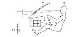
図1は実施形態に係る表示装置1の構成を例示する図である。本実施形態に係る表示装置1は機器に搭載されるHUDである。機器は、例えば車両、航空機、船舶等の移動体、又は操縦シミュレーションシステム、ホームシアターシステム等の非移動体であり得る。以下では表示装置1の一例として、自動車に搭載されたHUDについて説明する。  FIG. 1 is a diagram illustrating a configuration of a display device 1 according to the embodiment. The display device 1 according to the present embodiment is a HUD mounted on a device. The device may be a moving body such as a vehicle, an aircraft, and a ship, or a non-moving body such as an operation simulation system and a home theater system. Below, HUD mounted in the motor vehicle as an example of the display apparatus 1 is demonstrated.

表示装置1は光源部11、走査ミラー12、スクリーン13、第1の平面ミラー14(第1のミラー)、第2の平面ミラー15(第2のミラー)、及び凹面ミラー16を含む。  The display device 1 includes alight source unit 11, ascanning mirror 12, ascreen 13, a first plane mirror 14 (first mirror), a second plane mirror 15 (second mirror), and aconcave mirror 16.

フロントガラス17は光束の一部を透過し残部を反射する機能(部分反射機能)を有する透過反射部材である。フロントガラス17は観察者(運転者)10に前方の現実空間を視認させると共に、観察者10に所定の情報を提供する虚像25を視認させる半透過鏡として機能する。フロントガラス17は曲面を含んで構成されてもよい。虚像25は例えば車両情報(速度、走行距離等)、ナビゲーション情報(経路案内、交通情報等)、警告情報(衝突警報等)等を観察者10に提供する。虚像25はフロントガラス17の前方の現実空間と重畳するように表示されてもよい。なお、フロントガラス17と同じ機能(部分反射機能)を有する個別の透過反射部材としての半透過鏡(コンバイナ)を利用してもよい。  Thewindshield 17 is a transmission / reflection member having a function (partial reflection function) of transmitting a part of the light beam and reflecting the remaining part. Thewindshield 17 functions as a semi-transparent mirror that allows the observer (driver) 10 to visually recognize the real space ahead and visually recognize thevirtual image 25 that provides theobserver 10 with predetermined information. Thewindshield 17 may include a curved surface. Thevirtual image 25 provides, for example, vehicle information (speed, travel distance, etc.), navigation information (route guidance, traffic information, etc.), warning information (collision warning, etc.) to theobserver 10. Thevirtual image 25 may be displayed so as to overlap the real space in front of thewindshield 17. In addition, you may utilize the semi-transmission mirror (combiner) as an individual permeation | transmission reflection member which has the same function (partial reflection function) as thewindshield 17. FIG.

光源部11はレーザ光を照射する。光源部11は例えばR,G,Bの3色のレーザ光を合成したレーザ光を照射してもよい。光源部11から射出されたレーザ光は走査ミラー12の反射面に導かれる。  Thelight source unit 11 emits laser light. For example, thelight source unit 11 may irradiate a laser beam obtained by combining laser beams of three colors of R, G, and B. The laser light emitted from thelight source unit 11 is guided to the reflection surface of thescanning mirror 12.

走査ミラー12はMEMS(Micro Electro Mechanical Systems)等を利用してレーザ光の進行方向を変化させるデバイスである。走査ミラー12は例えば、直交する2軸に対して揺動する単一の微小なミラー、1軸に対して揺動又は回転する2つのミラーからなるミラー系等を利用して構成される。  Thescanning mirror 12 is a device that changes the traveling direction of laser light using MEMS (Micro Electro Mechanical Systems) or the like. Thescanning mirror 12 is configured using, for example, a single minute mirror that swings with respect to two orthogonal axes and a mirror system that includes two mirrors that swing or rotate with respect to one axis.

走査ミラー12から射出したレーザ光はスクリーン13を走査し、スクリーン13に2次元像である中間像を形成する。スクリーン13はレーザ光を所定の発散角で発散させる機能を有し、例えばマイクロレンズアレイ等を利用して構成される。  The laser beam emitted from thescanning mirror 12 scans thescreen 13 and forms an intermediate image which is a two-dimensional image on thescreen 13. Thescreen 13 has a function of diverging laser light at a predetermined divergence angle, and is configured using, for example, a microlens array.

第2の平面ミラー15はスクリーン13から射出された光を第1の平面ミラー14に反射させる。なお、第2の平面ミラー15を用いずに、スクリーン13から射出された光を直接第1の平面ミラー14に入射させてもよい。第2の平面ミラー15は設計上の必要性に応じて適宜設置されればよい。例えば、図1に示すように、表示装置1の収納スペースの制約によりスクリーン13から射出された光を直接第1の平面ミラー14に入射させることができない場合には、第2の平面ミラー15を設置することにより、スクリーン13からの光を間接的に第1の平面ミラー14に入射させることができる。  Thesecond plane mirror 15 reflects the light emitted from thescreen 13 to thefirst plane mirror 14. Note that the light emitted from thescreen 13 may be directly incident on thefirst plane mirror 14 without using thesecond plane mirror 15. The2nd plane mirror 15 should just be installed suitably according to the design necessity. For example, as shown in FIG. 1, when the light emitted from thescreen 13 cannot be directly incident on thefirst plane mirror 14 due to the storage space limitation of the display device 1, thesecond plane mirror 15 is By installing, the light from thescreen 13 can be incident on the firstflat mirror 14 indirectly.

第1の平面ミラー14は、スクリーン13側から照射された光を凹面ミラー16に反射させる。「スクリーン13側から照射された光」は、本実施形態においては、スクリーン13から射出され、第2の平面ミラー15により反射された光であるが、これに限られるものではなく、例えばスクリーン13から直接照射された光、スクリーン13から第1の平面ミラー14までの光路上に設置された1つ以上の光学部材(第2の平面ミラー15を含む)を介して照射された光等であってもよい。また、第1の平面ミラー14は凹面ミラー16から照射された光をフロントガラス17に反射させる。スクリーン13側から照射された光は、後述する第1の平面ミラー14上の第1の反射領域により反射される。凹面ミラー16から照射された光は、後述する第1の平面ミラー14上の第2の反射領域により反射される。  Thefirst plane mirror 14 reflects the light irradiated from thescreen 13 side to theconcave mirror 16. In the present embodiment, “light irradiated from thescreen 13 side” is light emitted from thescreen 13 and reflected by thesecond plane mirror 15, but is not limited thereto. Directly irradiated from the screen, light irradiated through one or more optical members (including the second plane mirror 15) installed on the optical path from thescreen 13 to thefirst plane mirror 14. May be. Thefirst plane mirror 14 reflects the light emitted from theconcave mirror 16 to thewindshield 17. The light emitted from thescreen 13 side is reflected by a first reflection region on a firstflat mirror 14 described later. The light emitted from theconcave mirror 16 is reflected by a second reflection region on the firstflat mirror 14 described later.

凹面ミラー16は第1の平面ミラー14の第1の反射領域から照射された光を第1の平面ミラー14の第2の反射領域に反射させる。凹面ミラー16はフロントガラス17の湾曲形状による画像の歪みを補正するように設計及び配置されている。凹面ミラー16から射出された光は第1の平面ミラー14によりフロントガラス17に反射される。これにより、スクリーン13に形成された中間像を構成する光はフロントガラス17に向けて投射され、観察者10はフロントガラス17で反射された光により虚像25を視認することができるようになる。  Theconcave mirror 16 reflects the light emitted from the first reflection region of thefirst plane mirror 14 to the second reflection region of thefirst plane mirror 14. Theconcave mirror 16 is designed and arranged to correct image distortion due to the curved shape of thewindshield 17. The light emitted from theconcave mirror 16 is reflected to thewindshield 17 by thefirst plane mirror 14. Thereby, the light which comprises the intermediate image formed in thescreen 13 is projected toward thewindshield 17, and theobserver 10 can visually recognize thevirtual image 25 with the light reflected by thewindshield 17. FIG.

図1中、X軸は表示装置1が搭載される機器(本実施形態においては自動車)の左右方向の軸を示し、Y軸は機器の上下方向の軸を示し、Z軸は機器の前後方向の軸を示す。  In FIG. 1, the X axis indicates the horizontal axis of the device (automobile in this embodiment) on which the display device 1 is mounted, the Y axis indicates the vertical axis of the device, and the Z axis indicates the longitudinal direction of the device. Indicates the axis.

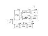
図2は実施形態に係る表示装置1のハードウェア構成を例示するブロック図である。本例の表示装置1はFPGA(Field-Programmable Gate Array)101、CPU(Central Processing Unit)102、ROM(Read Only Memory)103、RAM(Random Access Memory)104、I/F(Interface)105、バスライン106、LD(Laser Diode)109、LDドライバ110、MEMS111、及びMEMSコントローラ112を含む。  FIG. 2 is a block diagram illustrating a hardware configuration of the display device 1 according to the embodiment. The display device 1 of this example includes an FPGA (Field-Programmable Gate Array) 101, a CPU (Central Processing Unit) 102, a ROM (Read Only Memory) 103, a RAM (Random Access Memory) 104, an I / F (Interface) 105, a bus. Aline 106, an LD (Laser Diode) 109, anLD driver 110, a MEMS 111, and aMEMS controller 112 are included.

LD109は光源部11の一部を構成する半導体発光素子である。LDドライバ110はLD109を駆動する駆動信号を生成する回路である。MEMS111は走査ミラー12の一部を構成し、ミラーを変位させるデバイスである。MEMSコントローラ112はMEMS111を駆動する駆動信号を生成する回路である。FPGA101は表示装置1の設計者による設定変更が可能な集積回路である。LDドライバ110及びMEMSコントローラ112はFPGA101からの制御信号に応じて駆動信号を生成する。CPU102は表示装置1全体を制御するための処理を行う集積回路である。ROM103はCPU102を制御するプログラムを記憶する記憶装置である。RAM104はCPU102のワークエリアとして機能する記憶装置である。I/F105は外部装置と通信するためのインターフェースであり、例えば自動車のCAN(Controller Area Network)等に接続される。  TheLD 109 is a semiconductor light emitting element that constitutes a part of thelight source unit 11. TheLD driver 110 is a circuit that generates a drive signal for driving theLD 109. The MEMS 111 is a device that constitutes a part of thescanning mirror 12 and displaces the mirror. TheMEMS controller 112 is a circuit that generates a drive signal for driving the MEMS 111. TheFPGA 101 is an integrated circuit that can be changed by the designer of the display device 1. TheLD driver 110 and theMEMS controller 112 generate drive signals in accordance with control signals from theFPGA 101. TheCPU 102 is an integrated circuit that performs processing for controlling the entire display device 1. TheROM 103 is a storage device that stores a program for controlling theCPU 102. TheRAM 104 is a storage device that functions as a work area for theCPU 102. The I /F 105 is an interface for communicating with an external device, and is connected to a CAN (Controller Area Network) of an automobile, for example.

図3は実施形態に係る表示装置1の機能構成を例示するブロック図である。本例の表示装置1は車両情報入力部201、外部情報入力部202、画像生成部203、及び画像表示部204を含む。車両情報入力部201はCAN等から自動車の情報(速度、走行距離等の情報)を取得する機能部である。車両情報入力部201はI/F105、CPU102、ROM103に記憶されたプログラム等により構成される。外部情報入力部202は外部ネットワークから自動車外部の情報(GPSからの位置情報、ナビゲーションシステムからの経路情報、交通情報等)を取得する機能部である。外部情報入力部202はI/F105、CPU102、ROM103に記憶されたプログラム等により構成される。画像生成部203は車両情報入力部201及び外部情報入力部202により取得された情報に基づいて、虚像25の構成を決定し、虚像25を表示するための表示情報を生成する機能部である。画像生成部203はI/F105、CPU102、ROM103に記憶されたプログラム等により構成される。画像表示部204は画像生成部203により生成された表示情報に基づいて、所定のスクリーン(本実施形態においてはフロントガラス17)に虚像25を表示させる機能部である。画像表示部204はCPU102、FPGA101、LD109、LDドライバ110、MEMS111、MEMSコントローラ112等により構成される。制御部211は虚像25の位置、明るさ等を調整するための処理を行う機能部であり、FPGA101、LDドライバ110、MEMSコントローラ112等を制御する信号を生成する。  FIG. 3 is a block diagram illustrating a functional configuration of the display device 1 according to the embodiment. The display device 1 of this example includes a vehicleinformation input unit 201, an external information input unit 202, animage generation unit 203, and an image display unit 204. The vehicleinformation input unit 201 is a functional unit that acquires automobile information (information such as speed and travel distance) from CAN or the like. The vehicleinformation input unit 201 includes an I /F 105, aCPU 102, a program stored in theROM 103, and the like. The external information input unit 202 is a functional unit that acquires information outside the vehicle (position information from GPS, route information from the navigation system, traffic information, etc.) from an external network. The external information input unit 202 includes an I /F 105, aCPU 102, a program stored in theROM 103, and the like. Theimage generation unit 203 is a functional unit that determines the configuration of thevirtual image 25 based on the information acquired by the vehicleinformation input unit 201 and the external information input unit 202 and generates display information for displaying thevirtual image 25. Theimage generation unit 203 includes an I /F 105, aCPU 102, a program stored in theROM 103, and the like. The image display unit 204 is a functional unit that displays thevirtual image 25 on a predetermined screen (thewindshield 17 in the present embodiment) based on the display information generated by theimage generation unit 203. The image display unit 204 includes aCPU 102,FPGA 101,LD 109,LD driver 110, MEMS 111,MEMS controller 112, and the like. The control unit 211 is a functional unit that performs processing for adjusting the position, brightness, and the like of thevirtual image 25, and generates a signal that controls theFPGA 101, theLD driver 110, theMEMS controller 112, and the like.

図4は実施形態に係る光源部11の具体的構成を例示する図である。本例の光源部11は光源素子301R,301G,301B、カップリングレンズ302R,302G,302B、アパーチャ303R,303G,303B、合成素子304,305,306、及びレンズ307を含む。3色(R,G,B)の光源素子301R,301G,301Bはそれぞれ単数又は複数の発光点を有するLDであり、互いに異なる波長λR,λG,λB(例えばλR=640nm,λG=530nm,λB=445nm)の光束を放射する。放射された各光束はそれぞれカップリングレンズ302R,302G,302Bによりカップリングされる。カップリングされた各光束はそれぞれアパーチャ303R,303G,303Bにより整形される。アパーチャ303R,303G,303Bは光束の発散角等の所定の条件に応じた形状(例えば円形、楕円形、長方形、正方形等)を有する。アパーチャ303R,303G,303Bにより整形された各光束は3つの合成素子304,305,306により合成される。合成素子304,305,306はプレート状又はプリズム状のダイクロイックミラーであり、波長に応じて光束を反射又は透過し、1つの光束に合成する。合成された光束はレンズ307を通り、走査ミラー12に導かれる。  FIG. 4 is a diagram illustrating a specific configuration of thelight source unit 11 according to the embodiment. Thelight source unit 11 of this example includeslight source elements 301R, 301G, and 301B,coupling lenses 302R, 302G, and 302B,apertures 303R, 303G, and 303B, combiningelements 304, 305, and 306, and alens 307. The three color (R, G, B)light source elements 301R, 301G, 301B are LDs each having one or a plurality of light emitting points, and have different wavelengths λR, λG, λB (for example, λR = 640 nm, λG = 530 nm, λB). = 445 nm). The emitted light beams are respectively coupled by couplinglenses 302R, 302G, and 302B. The coupled light beams are shaped by theapertures 303R, 303G, and 303B, respectively. Theapertures 303R, 303G, and 303B have shapes (for example, a circle, an ellipse, a rectangle, and a square) according to predetermined conditions such as a divergence angle of a light beam. The light beams shaped by theapertures 303R, 303G, and 303B are combined by the three combiningelements 304, 305, and 306. The synthesizingelements 304, 305, and 306 are plate-like or prism-like dichroic mirrors that reflect or transmit a light beam according to a wavelength and synthesize it into one light beam. The combined light flux passes through thelens 307 and is guided to thescanning mirror 12.

図5は実施形態に係る走査ミラー12の具体的構成を例示する図である。本例の走査ミラー12は半導体プロセスにより製造されるMEMSミラーであり、ミラー351、蛇行状梁部352、枠部材353、及び圧電部材354を含む。ミラー351は光源部11から射出されたレーザ光をスクリーン13側に反射する反射面を有する。ミラー351を挟んで一対の蛇行状梁部352が形成されている。蛇行状梁部352は複数の折り返し部を有し、折り返し部は交互に配置される第1の梁部352aと第2の梁部352bとから構成されている。蛇行状梁部352は枠部材353に支持されている。圧電部材354は隣接する第1の梁部352aと第2の梁部352bとを接続するように配置されている。圧電部材354は第1の梁部352aと第2の梁部352bとに異なる電圧を印加し、各梁部352a,352bに反りを発生させる。これにより、隣接する梁部352a,352bが異なる方向に撓む。撓みが累積されることにより、ミラー351は左右方向の軸を中心として垂直方向に回転する。このような構成により、垂直方向への光走査が低電圧で可能となる。上下方向の軸を中心とした水平方向の光走査はミラー351に接続されたトーションバー等を利用した共振により行われる。  FIG. 5 is a diagram illustrating a specific configuration of thescanning mirror 12 according to the embodiment. Thescanning mirror 12 of this example is a MEMS mirror manufactured by a semiconductor process, and includes amirror 351, ameandering beam portion 352, aframe member 353, and apiezoelectric member 354. Themirror 351 has a reflection surface that reflects the laser light emitted from thelight source unit 11 toward thescreen 13. A pair ofmeandering beam portions 352 is formed with themirror 351 interposed therebetween. Themeandering beam portion 352 has a plurality of folded portions, and the folded portions are composed offirst beam portions 352a andsecond beam portions 352b that are alternately arranged. Theserpentine beam portion 352 is supported by theframe member 353. Thepiezoelectric member 354 is disposed so as to connect the adjacentfirst beam portion 352a and thesecond beam portion 352b. Thepiezoelectric member 354 applies different voltages to thefirst beam portion 352a and thesecond beam portion 352b, and causes thebeam portions 352a and 352b to warp. Thereby, theadjacent beam parts 352a and 352b bend in different directions. As the deflection is accumulated, themirror 351 rotates in the vertical direction about the left-right axis. With such a configuration, optical scanning in the vertical direction can be performed at a low voltage. Optical scanning in the horizontal direction about the vertical axis is performed by resonance using a torsion bar or the like connected to themirror 351.

図6は実施形態に係るスクリーン13の具体的構成を例示する図である。本例のスクリーン13は六角形状を有する複数のマイクロレンズ371が隙間なく配列されたマイクロレンズアレイ構造を有している。スクリーン13は走査ミラー12から照射されたレーザ光を所定の発散角で発散させる。マイクロレンズ371の幅(対向する2辺間の距離)は200μm程度であり得る。マイクロレンズ371の形状を六角形とすることにより、複数のマイクロレンズ371を高密度で配列することができる。なお、マイクロレンズ371の形状は六角形に限られるものではなく、例えば四角形、三角形等であってもよい。また、本例においては複数のマイクロレンズ371が規則正しく配列された構造を例示しているが、マイクロレンズ371の配列はこれに限られるものではなく、例えば各マイクロレンズ371の中心を互いに偏心させ、不規則な配列としてもよい。このように偏心させた配列を採用する場合、各マイクロレンズ371は互いに異なる形状となる。  FIG. 6 is a diagram illustrating a specific configuration of thescreen 13 according to the embodiment. Thescreen 13 of this example has a microlens array structure in which a plurality ofhexagonal microlenses 371 are arranged without gaps. Thescreen 13 diverges the laser light emitted from thescanning mirror 12 at a predetermined divergence angle. The width of the microlens 371 (distance between two opposing sides) may be about 200 μm. By making the shape of themicrolens 371 hexagonal, a plurality ofmicrolenses 371 can be arranged with high density. Note that the shape of themicrolens 371 is not limited to a hexagon, and may be, for example, a quadrangle or a triangle. In this example, a structure in which a plurality ofmicrolenses 371 are regularly arranged is illustrated. However, the arrangement of themicrolenses 371 is not limited to this. For example, the centers of themicrolenses 371 are decentered from each other. It may be an irregular array. When such an eccentric arrangement is employed, themicrolenses 371 have different shapes.

上記構成によれば、スクリーン13に形成された中間像をフロントガラス17に拡大投影し、虚像25を表示することができる。このとき、虚像25内の表示情報の幾何学的形状を現実空間と整合するように調整することにより、観察者10に表示情報を現実空間に重畳するように知覚させることができる。  According to the above configuration, the intermediate image formed on thescreen 13 can be enlarged and projected onto thewindshield 17 to display thevirtual image 25. At this time, by adjusting the geometric shape of the display information in thevirtual image 25 so as to match the real space, theviewer 10 can perceive the display information to be superimposed on the real space.

図7は虚像25を現実空間に重畳させる際の組み付け上の問題点を例示する図である。図7中、実線は虚像25を現実空間に重畳させる場合における虚像25及び表示装置1の位置を示し、一点鎖線は虚像25を現実空間に重畳させない場合における虚像25及び表示装置1の位置を示している。重畳させない場合、観察者10が虚像25を見下ろす角度(俯角)を比較的大きく設定することができるため、表示装置1をZ軸方向において観察者10から比較的遠い位置に設置することができる。これに対し、重畳させる場合には、虚像25を遠方の風景に重畳させるために俯角を小さくする(虚像25を上方に表示する)必要があるため、表示装置1をZ軸方向において観察者10に比較的近い位置に設置する必要がある。しかしながら、表示装置1が設置される機器の構造上の制約により、表示装置1を観察者10に近い位置に設置することは困難である場合が多い。例えば、自動車においては、ダッシュボード内の手前側の部分にメータ機構、ペダル機構、空調機構、ハンドル機構等が配置されるため、この部分に表示装置1を設置できるスペースは限られる。そこで、表示装置1を特にZ軸方向に小型化し、表示装置1を観察者10に近い位置に設置できるようにすることが望まれる。  FIG. 7 is a diagram illustrating a problem in assembling when thevirtual image 25 is superimposed on the real space. In FIG. 7, the solid line indicates the position of thevirtual image 25 and the display device 1 when thevirtual image 25 is superimposed on the real space, and the alternate long and short dash line indicates the position of thevirtual image 25 and the display device 1 when thevirtual image 25 is not superimposed on the real space. ing. When not superposed, the angle at which theobserver 10 looks down the virtual image 25 (the depression angle) can be set to be relatively large, so that the display device 1 can be installed at a position relatively far from theobserver 10 in the Z-axis direction. On the other hand, in the case of superimposing, it is necessary to reduce the depression angle in order to superimpose thevirtual image 25 on a distant landscape (display thevirtual image 25 upward). It is necessary to install it at a position relatively close to. However, it is often difficult to install the display device 1 at a position close to theobserver 10 due to structural limitations of the device in which the display device 1 is installed. For example, in an automobile, a meter mechanism, a pedal mechanism, an air conditioning mechanism, a handle mechanism, and the like are disposed in the front portion of the dashboard, so that a space in which the display device 1 can be installed in this portion is limited. Therefore, it is desirable to downsize the display device 1 particularly in the Z-axis direction so that the display device 1 can be installed at a position close to theobserver 10.

また、虚像25を現実空間に重畳させる際には、観察者10の視差に基づく問題に対処する必要がある。上述したように、本実施形態に係る表示装置1によれば、観察者10は虚像25内の表示情報を現実空間に重畳させて知覚することができる。しかし、実際の表示情報はフロントガラス17近傍で視認されるため、表示情報と、表示情報が重畳される現実空間内の観察対象との間に視差が生ずる。  Further, when thevirtual image 25 is superimposed on the real space, it is necessary to deal with a problem based on the parallax of theobserver 10. As described above, according to the display device 1 according to the present embodiment, theobserver 10 can perceive the display information in thevirtual image 25 superimposed on the real space. However, since the actual display information is visually recognized in the vicinity of thewindshield 17, a parallax occurs between the display information and the observation target in the real space on which the display information is superimposed.

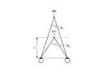
図8は観察対象401の結像位置に対応する輻輳角θ1と表示情報411の結像位置に対応する輻輳角θ2との関係を例示する図である。現実空間内の観察対象401の結像位置に対応する輻輳角θ1は、観察者10が観察対象401を視認する際に観察者10の両眼の視線が成す角度を示している。虚像25内の表示情報411の結像位置に対応する輻輳角θ2は、観察者10が表示情報411を視認する際に観察者10の両眼の視線が成す角度を示している。視差角θparaは|θ2−θ1|と定義される。視差角θparaが1degを超えるとき、観察者10は二重像を知覚し、不快や疲労を感じる場合が多い。従って、表示装置1は視差角θparaが1deg以下となるように設計されることが好ましい。例えば、視点位置から表示情報411の結像位置までの距離Lが3800mm以上であるとき、視点位置から観察対象401までの距離が2000mm以上である場合に、視差角θparaが1deg以下となる。  FIG. 8 is a diagram illustrating the relationship between the convergence angle θ1 corresponding to the imaging position of theobservation object 401 and the convergence angle θ2 corresponding to the imaging position of thedisplay information 411. The convergence angle θ1 corresponding to the imaging position of theobservation target 401 in the real space indicates the angle formed by the eyes of both eyes of theobserver 10 when theobserver 10 visually recognizes theobservation target 401. The convergence angle θ2 corresponding to the imaging position of thedisplay information 411 in thevirtual image 25 indicates the angle formed by the eyes of the eyes of theobserver 10 when theobserver 10 visually recognizes thedisplay information 411. The parallax angle θpara is defined as | θ2−θ1 |. When the parallax angle θpara exceeds 1 deg, theobserver 10 often perceives a double image and feels uncomfortable or fatigued. Accordingly, the display device 1 is preferably designed so that the parallax angle θpara is 1 deg or less. For example, when the distance L from the viewpoint position to the imaging position of thedisplay information 411 is 3800 mm or more, and the distance from the viewpoint position to theobservation object 401 is 2000 mm or more, the parallax angle θpara is 1 deg or less.

図9は視点位置から対象(観察対象401及び表示情報411を含む)までの距離(対象距離)と輻輳角との関係を例示する図である。輻輳角は観察者10の視点位置から対象までの距離に応じて、曲線421に示すように変化する。図9に示すように、対象距離が略3800mmのとき、輻輳角は略1degとなる。観察者10がフロントガラス17を通して視認可能な現実空間内の任意の位置に表示情報411を重畳させることができる対象距離(視点位置から観察対象401の結像位置までの距離)の範囲は、二点鎖線で示すように、輻輳角が±1degの範囲である。従って、視点位置から表示情報411の結像位置までの距離Lが3800mm以上であるとき、視点位置から観察対象401までの距離は2000mm以上であればよい。実際の使用状況(例えば、表示装置1を自動車等の移動体に搭載する場合)において、視点位置から表示情報411を重畳させたい観察対象401までの距離が2000mmより小さいことは稀である。  FIG. 9 is a diagram illustrating the relationship between the distance from the viewpoint position to the target (including theobservation target 401 and the display information 411) (target distance) and the convergence angle. The convergence angle changes as shown by acurve 421 according to the distance from the viewpoint position of theobserver 10 to the object. As shown in FIG. 9, when the target distance is approximately 3800 mm, the convergence angle is approximately 1 deg. The range of the target distance (distance from the viewpoint position to the imaging position of the observation object 401) at which thedisplay information 411 can be superimposed at an arbitrary position in the real space that theobserver 10 can visually recognize through thewindshield 17 is two. As indicated by the dashed line, the convergence angle is in the range of ± 1 deg. Therefore, when the distance L from the viewpoint position to the imaging position of thedisplay information 411 is 3800 mm or more, the distance from the viewpoint position to theobservation object 401 may be 2000 mm or more. In an actual usage situation (for example, when the display device 1 is mounted on a moving body such as an automobile), it is rare that the distance from the viewpoint position to theobservation target 401 on which thedisplay information 411 is to be superimposed is smaller than 2000 mm.

表示装置1内における光路長を一定に保ち、距離Lを長くすると、表示装置1内の光学系の倍率は大きくなる。光路長とは、中間像が形成されるスクリーン13から虚像25が投影されるフロントガラス17までの光の経路の長さである。光学系の倍率とは、虚像25の中間像に対する倍率であり、例えば虚像25の縦方向の長さを中間像又はスクリーン13の縦方向の長さで除した値α、虚像25の横方向の長さを中間像又はスクリーン13の横方向の長さで除した値β等である。光学系の倍率が大きくなると、公差による感度が増加し、表示装置1の組み付け精度に対する要求が高くなる。そのため、光学系の倍率が大きい程、観察者10の視点位置の変化に伴う虚像25の品質劣化が大きくなりやすい。一般に、距離Lを3800mm以上に設定するとき、光学系の倍率(α及びβの両方又はどちらか一方)は15倍より大きくなる場合が多い。光路長を長く取ることにより、距離Lを3800mm以上に維持したまま、光学系の倍率を15倍以下に抑えることができる。しかし、光路長を長くしようとするとき、表示装置1の大型化が問題となる。そこで、本実施形態に係る表示装置1は、表示装置1の大型化を招くことなく光路長を長く取るために、第1の平面ミラー14を備えている。  When the optical path length in the display device 1 is kept constant and the distance L is increased, the magnification of the optical system in the display device 1 increases. The optical path length is the length of the light path from thescreen 13 on which the intermediate image is formed to thewindshield 17 on which thevirtual image 25 is projected. The magnification of the optical system is a magnification with respect to the intermediate image of thevirtual image 25, for example, a value α obtained by dividing the vertical length of thevirtual image 25 by the vertical length of the intermediate image or thescreen 13, and the horizontal direction of thevirtual image 25. A value β obtained by dividing the length by the length of the intermediate image or the horizontal direction of thescreen 13 or the like. When the magnification of the optical system increases, the sensitivity due to tolerance increases, and the requirement for the assembly accuracy of the display device 1 increases. For this reason, as the magnification of the optical system increases, the quality degradation of thevirtual image 25 accompanying the change in the viewpoint position of theobserver 10 tends to increase. Generally, when the distance L is set to 3800 mm or more, the magnification (both α and / or β) of the optical system is often greater than 15 times. By taking a long optical path length, the magnification of the optical system can be suppressed to 15 times or less while the distance L is maintained at 3800 mm or more. However, an increase in the size of the display device 1 becomes a problem when attempting to increase the optical path length. Therefore, the display device 1 according to the present embodiment includes the firstflat mirror 14 in order to increase the optical path length without causing an increase in the size of the display device 1.

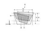
図10は実施形態に係る第1の平面ミラー14の構成を例示する図である。第1の平面ミラー14は第1の反射領域31、第2の反射領域32、及び共有反射領域33を有する。図10中、Z軸は機器(本実施形態においては自動車)の前後方向を示すと共に、光の反射方向に平行な方向を示す。X軸は機器の左右方向を示すと共に、光の反射方向に垂直な方向を示す。光の反射方向とは、第1の平面ミラー14により反射された光の進行方向、すなわち本実施形態においては、第2の平面ミラー15から第1の平面ミラー14を経て凹面ミラー16へ向かう光又は凹面ミラー16から第1の平面ミラー14を経てフロントガラス17へ向かう光の進行方向である。  FIG. 10 is a diagram illustrating the configuration of the firstflat mirror 14 according to the embodiment. The firstflat mirror 14 has afirst reflection region 31, asecond reflection region 32, and a sharedreflection region 33. In FIG. 10, the Z-axis indicates the front-rear direction of the device (automobile in this embodiment) and the direction parallel to the light reflection direction. The X axis indicates the left-right direction of the device and the direction perpendicular to the light reflection direction. The light reflection direction is the traveling direction of light reflected by thefirst plane mirror 14, that is, in this embodiment, the light traveling from thesecond plane mirror 15 to theconcave mirror 16 via thefirst plane mirror 14. Or it is the advancing direction of the light which goes to thewindshield 17 through the1st plane mirror 14 from theconcave mirror 16. FIG.

第1の反射領域31はスクリーン13側から照射された光を凹面ミラー16に反射させる領域である。「スクリーン13側から照射された光」は、本実施形態においては、スクリーン13から射出され、第2の平面ミラー15により反射された光であるが、これに限られるものではない。スクリーン13から射出された光は、第2の平面ミラー15を介さずに直接第1の平面ミラー14に照射されてもよい。また、スクリーン13から第1の平面ミラー14までの光路上に第2の平面ミラー15以外のミラーを設置し、スクリーン13から射出された光がこれらの複数のミラーを介して第1の反射領域31に照射されるようにしてもよい。第1の反射領域31は虚像25を最大表示する際に必要となる領域である。  Thefirst reflection region 31 is a region that reflects the light irradiated from thescreen 13 side to theconcave mirror 16. In the present embodiment, “light irradiated from thescreen 13 side” is light emitted from thescreen 13 and reflected by thesecond plane mirror 15, but is not limited thereto. The light emitted from thescreen 13 may be directly applied to thefirst plane mirror 14 without passing through thesecond plane mirror 15. Further, a mirror other than thesecond plane mirror 15 is installed on the optical path from thescreen 13 to thefirst plane mirror 14, and the light emitted from thescreen 13 passes through the plurality of mirrors to the first reflection region. 31 may be irradiated. Thefirst reflection area 31 is an area necessary for displaying thevirtual image 25 at the maximum.

第2の反射領域32は凹面ミラー16から照射された光をフロントガラス17に反射させる領域である。第2の反射領域32は虚像25を最大表示する際に必要となる領域である。  Thesecond reflection region 32 is a region that reflects the light emitted from theconcave mirror 16 to thewindshield 17. Thesecond reflection area 32 is an area necessary for displaying thevirtual image 25 at the maximum.

共有反射領域33は第1の反射領域31と第2の反射領域32とが重なる領域である。共有反射領域33は、スクリーン13側から照射された光を凹面ミラー16に反射させる領域、及び凹面ミラー16から照射された光をフロントガラス17に反射させる領域の両方として機能する。第1の平面ミラー14の反射面全体に対する共有反射領域33の占める割合が大きい程、第1の平面ミラー14を小型化することができる。  The sharedreflection area 33 is an area where thefirst reflection area 31 and thesecond reflection area 32 overlap. The sharedreflection area 33 functions as both an area for reflecting the light irradiated from thescreen 13 side to theconcave mirror 16 and an area for reflecting the light irradiated from theconcave mirror 16 to thewindshield 17. As the ratio of the sharedreflection region 33 to the entire reflection surface of thefirst plane mirror 14 increases, thefirst plane mirror 14 can be reduced in size.

上記のように、第1の平面ミラー14を用いて光を2回反射させることにより、中間像を形成するスクリーン13から虚像25を表示させるフロントガラス17までの光路長を長くすることができる。また、共有反射領域33を設けることにより、第1の平面ミラー14を小型化することができる。  As described above, by reflecting light twice using the firstflat mirror 14, the optical path length from thescreen 13 that forms the intermediate image to thewindshield 17 that displays thevirtual image 25 can be increased. Further, by providing the sharedreflection region 33, thefirst plane mirror 14 can be reduced in size.

図11は実施形態に係る第1の平面ミラー14により反射される光の入射角φ1,φ2を例示する図である。図11中、破線は虚像25の中央光線が観察者10の基準視点へ伝播する光路を示している。第2の平面ミラー15により反射された光は、第1の平面ミラー14上の第1の反射領域31へ入射角φ1で入射する。ここでの入射角φ1は、YZ平面から光学系(例えば第1の平面ミラー14)を観察した際の入射角とする。なお、「第2の平面ミラー15により反射された光」は、上記「スクリーン13側から照射された光」の一形態である。すなわち、「第2の平面ミラー15により反射された光」の代わりに、スクリーン13から射出された光が直接第1の平面ミラー14に照射されてもよい。また、スクリーン13から第1の平面ミラー14までの光路上に第2の平面ミラー15以外のミラーを設置し、スクリーン13から射出された光がこれらの複数のミラーを介して第1の反射領域31に照射されるようにしてもよい。  FIG. 11 is a diagram illustrating incident angles φ1 and φ2 of light reflected by the firstflat mirror 14 according to the embodiment. In FIG. 11, a broken line indicates an optical path through which the central ray of thevirtual image 25 propagates to the reference viewpoint of theobserver 10. The light reflected by thesecond plane mirror 15 enters thefirst reflection region 31 on thefirst plane mirror 14 at an incident angle φ1. The incident angle φ1 here is an incident angle when the optical system (for example, the first flat mirror 14) is observed from the YZ plane. The “light reflected by thesecond plane mirror 15” is a form of the “light irradiated from thescreen 13 side”. That is, instead of “the light reflected by thesecond plane mirror 15”, the light emitted from thescreen 13 may be directly applied to thefirst plane mirror 14. Further, a mirror other than thesecond plane mirror 15 is installed on the optical path from thescreen 13 to thefirst plane mirror 14, and the light emitted from thescreen 13 passes through the plurality of mirrors to the first reflection region. 31 may be irradiated.

凹面ミラー16により反射された光は、第1の平面ミラー14上の第2の反射領域32へ、入射角φ2で入射する。ここでの入射角φ2は、φ1と同様に、YZ平面から光学系を観察した際の入射角とする。  The light reflected by theconcave mirror 16 enters thesecond reflection region 32 on thefirst plane mirror 14 at an incident angle φ2. The incident angle φ2 here is the incident angle when the optical system is observed from the YZ plane, similarly to φ1.

本実施形態に係る表示装置1は、φ1>φ2が成り立つように設計されている。自動車等の機器に表示装置1を搭載するためのスペースは、上述したように各種機構の配置により制約を受ける場合が多い。そのため、第2の平面ミラー15(光源部11)と凹面ミラー16とを、第1の平面ミラー14の設置位置を基準としてZ軸方向上の同じ側に設置することは難しい。このような場合、φ1>φ2が成り立つように設計することにより、第2の平面ミラー15(光源部11)と凹面ミラー16とを、第1の平面ミラー14を挟んで互いに異なる側に設置することが可能となり、表示装置1の小型化を図ることが可能となる。  The display device 1 according to the present embodiment is designed so that φ1> φ2. As described above, the space for mounting the display device 1 on a device such as an automobile is often restricted by the arrangement of various mechanisms. Therefore, it is difficult to install the second plane mirror 15 (light source unit 11) and theconcave mirror 16 on the same side in the Z-axis direction with the installation position of thefirst plane mirror 14 as a reference. In such a case, by designing so that φ1> φ2 holds, the second plane mirror 15 (light source unit 11) and theconcave mirror 16 are installed on different sides with thefirst plane mirror 14 in between. Accordingly, the display device 1 can be reduced in size.

入射角φ1は入射角φ2の1.6倍程度であることが望ましい。これは、ダッシュボード内の手前側の部分に上述したような各種機構が配置され、ダッシュボード内の奥側の部分にフロントガラス17の保持機構やボンネット内部の部品が存在する状況下において、所望の位置に第2の平面ミラー15(光源部11)及び凹面ミラー16を配置できるようにするためである。これにより、虚像25の縦方向の大きさを可能な限り大きくすることができる。  The incident angle φ1 is desirably about 1.6 times the incident angle φ2. This is desirable in a situation where the various mechanisms as described above are arranged in the front portion of the dashboard, and the holding mechanism of thewindshield 17 and the parts inside the bonnet are present in the rear portion of the dashboard. This is because the second plane mirror 15 (light source unit 11) and theconcave mirror 16 can be disposed at the position of. Thereby, the vertical size of thevirtual image 25 can be increased as much as possible.

なお、1.2×φ2≦φ1≦2.0×φ2の関係が成り立てば、実質的に上記効果を得ることが可能である。φ1<1.2×φ2となるとき、凹面ミラー16又はボンネット上部の開口部(凹面ミラー16からの光をフロントガラス17に導く開口部)により虚像25の下部が制限される。φ1>2.0×φ2となるとき、第2の平面ミラー15(光源部11)又はボンネット上部の開口部により虚像25の上部が制限される。そのため、1.2×φ2≦φ1≦2.0×φ2の関係が成り立たないとき、虚像25は小さくなり、表示装置1の品質が低下することとなる。  If the relationship of 1.2 × φ2 ≦ φ1 ≦ 2.0 × φ2 is established, the above effect can be substantially obtained. When φ1 <1.2 × φ2, the lower portion of thevirtual image 25 is limited by theconcave mirror 16 or the opening at the top of the bonnet (the opening that guides light from theconcave mirror 16 to the windshield 17). When φ1> 2.0 × φ2, the upper portion of thevirtual image 25 is limited by the second flat mirror 15 (light source unit 11) or the opening at the top of the bonnet. Therefore, when the relationship of 1.2 × φ2 ≦ φ1 ≦ 2.0 × φ2 is not established, thevirtual image 25 becomes small and the quality of the display device 1 is deteriorated.

また、図10に示すように、第1の反射領域31のZ軸方向(光の反射方向に平行な方向)の径をZ1、第1の反射領域31のX軸方向(光の反射方向に垂直な方向)の径をX1、第2の反射領域32のZ軸方向の径をZ2、第2の反射領域32のX軸方向の径をX2とするとき、Z1>Z2又はX1<X2の関係が成り立つ。本実施形態においては、Z1>Z2且つX1<X2の関係が成り立っている。このような関係が成り立つことにより、第1の反射領域31と第2の反射領域32とを重ねることができ、共有反射領域33を形成することができる。  Further, as shown in FIG. 10, the diameter of thefirst reflection region 31 in the Z-axis direction (direction parallel to the light reflection direction) is Z1, and the X-axis direction of the first reflection region 31 (in the light reflection direction). Z1> Z2 or X1 <X2 where X1 is the diameter in the vertical direction), Z2 is the diameter in the Z-axis direction of thesecond reflection region 32, and X2 is the diameter in the X-axis direction of thesecond reflection region 32. A relationship is established. In the present embodiment, the relationship of Z1> Z2 and X1 <X2 is established. By satisfying such a relationship, thefirst reflection region 31 and thesecond reflection region 32 can be overlapped, and the sharedreflection region 33 can be formed.

また、Z1/X1をA1、Z2/X2をA2とするとき、(A1/A2)<2の関係が成り立つことが好ましい。A1は第1の反射領域31のZ軸方向への圧縮の度合いを示す値であり、A2は第2の反射領域32のZ軸方向への圧縮の度合いを示す値である。(A1/A2)<2の関係が成り立つとき、第2の反射領域32は第1の反射領域31よりZ軸方向に十分に圧縮された状態であるといえる。このような状態にすることにより、凹面ミラー16から第2の反射領域32に入射する光の入射角φ2が、第2の平面ミラー15(第2の平面ミラー15が設けられていない場合にはスクリーン13)から第1の反射領域31に入射する光の入射角φ1より小さくなる。これにより、凹面ミラー16から射出した光の収差が小さくなり、虚像25の画質が向上する。  Further, when Z1 / X1 is A1 and Z2 / X2 is A2, it is preferable that the relationship of (A1 / A2) <2 is satisfied. A1 is a value indicating the degree of compression of the firstreflective region 31 in the Z-axis direction, and A2 is a value indicating the degree of compression of the secondreflective region 32 in the Z-axis direction. When the relationship of (A1 / A2) <2 holds, it can be said that the secondreflective region 32 is sufficiently compressed in the Z-axis direction than the firstreflective region 31. By making such a state, the incident angle φ2 of the light incident on the second reflectingregion 32 from theconcave mirror 16 becomes the second plane mirror 15 (in the case where thesecond plane mirror 15 is not provided). It becomes smaller than the incident angle φ1 of the light incident on thefirst reflection area 31 from the screen 13). Thereby, the aberration of the light emitted from theconcave mirror 16 is reduced, and the image quality of thevirtual image 25 is improved.

図12は比較例に係る第1の平面ミラー515と実施形態に係る第1の平面ミラー14とを比較した状態を例示する図である。比較例に係る第1の平面ミラー515には、第1の反射領域31と第2の反射領域32とが重なり合う領域が存在しない。これに対し、実施形態に係る第1の平面ミラー14には、第1の反射領域31と第2の反射領域32とが重なり合う共有反射領域33が存在している。これにより、実施形態に係る第1の平面ミラー14のZ軸方向の長さは、比較例に係る第1の平面ミラー515のZ軸方向の長さより短くなる。なお、比較例に係る第1の反射領域31及び第2の反射領域32の大きさ及び形状は、実施形態に係る第1の反射領域31及び第2の反射領域32と同一である。このように、本実施形態によれば、第1の平面ミラー14、延いては表示装置1全体をZ軸方向に小型化することができる。  FIG. 12 is a diagram illustrating a state in which the firstflat mirror 515 according to the comparative example is compared with the firstflat mirror 14 according to the embodiment. In the firstflat mirror 515 according to the comparative example, there is no region where thefirst reflection region 31 and thesecond reflection region 32 overlap. In contrast, in the firstflat mirror 14 according to the embodiment, there is a sharedreflection region 33 in which thefirst reflection region 31 and thesecond reflection region 32 overlap. Thereby, the length of thefirst plane mirror 14 according to the embodiment in the Z-axis direction is shorter than the length of thefirst plane mirror 515 according to the comparative example in the Z-axis direction. In addition, the magnitude | size and shape of the 1streflective area 31 and the 2ndreflective area 32 which concern on a comparative example are the same as the 1streflective area 31 and the 2ndreflective area 32 which concern on embodiment. As described above, according to the present embodiment, the firstflat mirror 14 and thus the entire display device 1 can be downsized in the Z-axis direction.

上記のように、第1の平面ミラー14を用いて光を2回反射させることにより、中間像を形成するスクリーン13から虚像25を表示させるフロントガラス17までの光路長を長くすることができる。また、共有反射領域33を設けることにより、第1の平面ミラー14を小型化することができる。以上のように、本実施形態によれば、表示装置1の大型化を招くことなく、虚像25の画質を向上させることが可能となる。  As described above, by reflecting light twice using the firstflat mirror 14, the optical path length from thescreen 13 that forms the intermediate image to thewindshield 17 that displays thevirtual image 25 can be increased. Further, by providing the sharedreflection region 33, thefirst plane mirror 14 can be reduced in size. As described above, according to the present embodiment, the image quality of thevirtual image 25 can be improved without increasing the size of the display device 1.

以上、本発明の実施形態を説明したが、上記実施形態は例として提示したものであり、発明の範囲を限定することを意図するものではない。この新規な実施形態はその他の様々な形態で実施されることが可能であり、発明の要旨を逸脱しない範囲で種々の省略、置き換え、変更、及び組み合わせを行うことができる。この実施形態及びその変形は発明の範囲及び要旨に含まれるとともに、特許請求の範囲に記載された発明とその均等の範囲に含まれる。  As mentioned above, although embodiment of this invention was described, the said embodiment is shown as an example and is not intending limiting the range of invention. The novel embodiment can be implemented in various other forms, and various omissions, replacements, changes, and combinations can be made without departing from the scope of the invention. This embodiment and its modifications are included in the scope and gist of the invention, and are included in the invention described in the claims and the equivalents thereof.

1 表示装置
10 観察者
11 光源部
12 走査ミラー
13 スクリーン
14 第1の平面ミラー(第1のミラー)
15 第2の平面ミラー(第2のミラー)
16 凹面ミラー
17 フロントガラス
25 虚像
31 第1の反射領域
32 第2の反射領域
33 共有反射領域
101 FPGA
102 CPU
103 ROM
104 RAM
105 I/F
106 バスライン
109 LD
110 LDドライバ
111 MEMS
112 MEMSコントローラ
201 車両情報入力部
202 外部情報入力部
203 画像生成部
204 画像表示部
211 制御部
301R,301G,301B 光源素子
302R,302G,302B カップリングレンズ
303R,303G,303B アパーチャ
304,305,306 合成素子
307 レンズ
351 ミラー
352 蛇行状梁部
352a 第1の梁部
352b 第2の梁部
353 枠部材
354 圧電部材
371 マイクロレンズ
401 観察対象
411 表示情報
DESCRIPTION OF SYMBOLS 1Display apparatus 10Observer 11Light source part 12Scanning mirror 13Screen 14 1st plane mirror (1st mirror)
15 Second plane mirror (second mirror)
16Concave mirror 17Windshield 25Virtual image 31First reflection area 32Second reflection area 33Shared reflection area 101 FPGA
102 CPU
103 ROM
104 RAM
105 I / F
106Bus line 109 LD
110 LD driver 111 MEMS
DESCRIPTION OFSYMBOLS 112MEMS controller 201 Vehicle information input part 202 Externalinformation input part 203 Image generation part 204 Image display part 211Control part 301R, 301G, 301BLight source element 302R, 302G,302B Coupling lens 303R, 303G, 303B Aperture 304,305,306Composite element 307Lens 351 Mirror 352Serpentine beam portion 352aFirst beam portion 352bSecond beam portion 353Frame member 354Piezoelectric member 371Microlens 401Observation object 411 Display information

特開2009−115908号公報JP 2009-115908 A

Claims (9)

Translated fromJapanese
中間像が形成されるスクリーンと、
第1のミラーと、
前記第1のミラーから照射された光を前記第1のミラーに反射させる凹面ミラーと、
を備え、
前記第1のミラーは、前記スクリーン側から照射された光を前記凹面ミラーに反射させる第1の反射領域と、前記凹面ミラーから照射された光を反射させる第2の反射領域と、前記第1の反射領域と前記第2の反射領域とが重なる共有反射領域とを含む、
表示装置。
A screen on which an intermediate image is formed;
A first mirror;
A concave mirror that reflects the light emitted from the first mirror to the first mirror;
With
The first mirror includes a first reflection region that reflects light irradiated from the screen side to the concave mirror, a second reflection region that reflects light irradiated from the concave mirror, and the first mirror A shared reflection region where the reflection region overlaps the second reflection region,
Display device.
前記スクリーン側から照射され前記第1の反射領域へ入射する光の入射角をφ1、前記凹面ミラーから照射され前記第2の反射領域へ入射する光の入射角をφ2とするとき、φ1≧φ2の関係が成り立つように構成されている、
請求項1に記載の表示装置。
When the incident angle of light irradiated from the screen side and incident on the first reflection region is φ1, and the incident angle of light irradiated from the concave mirror and incident on the second reflection region is φ2, φ1 ≧ φ2 It is configured so that the relationship of
The display device according to claim 1.
前記スクリーン側から照射され前記第1の反射領域へ入射する光の入射角をφ1、前記凹面ミラーから照射され前記第2の反射領域へ入射する光の入射角をφ2とするとき、1.2×φ2≦φ1≦2.0×φ2の関係が成り立つように構成されている、
請求項1に記載の表示装置。
When the incident angle of light incident from the screen side and incident on the first reflective region is φ1, and the incident angle of light incident from the concave mirror and incident on the second reflective region is φ2, 1.2 It is configured so that the relationship of × φ2 ≦ φ1 ≦ 2.0 × φ2 is established.
The display device according to claim 1.
前記第1の反射領域の光の反射方向に平行な方向の径をZ1、前記第1の反射領域の光の反射方向に垂直な方向の径をX1、前記第2の反射領域の光の反射方向に平行な方向の径をZ2、前記第2の反射領域の光の反射方向に垂直な方向の径をX2とするとき、Z1>Z2又はX1<X2の関係が成り立つように構成されている、
請求項1〜3のいずれか1項に記載の表示装置。
The diameter of the first reflection region in the direction parallel to the light reflection direction is Z1, the diameter of the first reflection region in the direction perpendicular to the light reflection direction is X1, and the reflection of the light in the second reflection region. When the diameter in the direction parallel to the direction is Z2 and the diameter in the direction perpendicular to the light reflection direction of the second reflection region is X2, the relationship of Z1> Z2 or X1 <X2 is established. ,
The display device according to claim 1.
Z1/X1をA1、Z2/X2をA2とするとき、(A1/A2)<2の関係が成り立つ、
請求項4に記載の表示装置。
When Z1 / X1 is A1 and Z2 / X2 is A2, the relationship of (A1 / A2) <2 holds.
The display device according to claim 4.
虚像の前記中間像に対する倍率が15倍以下である、
請求項1〜5のいずれか1項に記載の表示装置。
The magnification of the virtual image with respect to the intermediate image is 15 times or less,
The display apparatus of any one of Claims 1-5.
前記スクリーンから射出された光を前記第1のミラーに反射させる第2のミラー、
を更に備える請求項1〜6のいずれか1項に記載の表示装置。
A second mirror that reflects the light emitted from the screen to the first mirror;
The display device according to claim 1, further comprising:
請求項1〜7のいずれか1項に記載の表示装置と、
前記中間像を形成する光が照射されることにより虚像を形成する透過反射部材と、
を備える機器。
A display device according to any one of claims 1 to 7,
A transmissive reflecting member that forms a virtual image by being irradiated with light that forms the intermediate image;
Equipment with.
前記透過反射部材は、曲面を含む部材である、
請求項8に記載の機器。
The transmission / reflection member is a member including a curved surface,
The device according to claim 8.
JP2017234180A2017-03-022017-12-06Display unit and apparatusWithdrawnJP2018146950A (en)

Priority Applications (2)

Application NumberPriority DateFiling DateTitle
EP18153278.9AEP3370103A1 (en)2017-03-022018-01-24Display device and apparatus
US15/886,401US10831021B2 (en)2017-03-022018-02-01Display device and including a screen concave mirror and flat mirror

Applications Claiming Priority (2)

Application NumberPriority DateFiling DateTitle
JP20170392562017-03-02

Publications (1)

Publication NumberPublication Date
JP2018146950Atrue JP2018146950A (en)2018-09-20

Family

ID=63588819

Family Applications (1)

Application NumberTitlePriority DateFiling Date
JP2017234180AWithdrawnJP2018146950A (en)2017-03-022017-12-06Display unit and apparatus

Country Status (1)

CountryLink
JP (1)JP2018146950A (en)

Cited By (2)

* Cited by examiner, † Cited by third party
Publication numberPriority datePublication dateAssigneeTitle
US10950152B2 (en)2017-03-152021-03-16Ricoh Company, Ltd.Laser scanning display with luminance adjustment
US11048081B2 (en)2018-11-082021-06-29Ricoh Company, Ltd.Display device, display system, and mobile object

Citations (9)

* Cited by examiner, † Cited by third party
Publication numberPriority datePublication dateAssigneeTitle
JP2009115908A (en)*2007-11-022009-05-28Fujinon CorpMirror optical system and headup display
JP2009122582A (en)*2007-11-192009-06-04Fujinon CorpProjection optical system and head-up display apparatus
JP2009222881A (en)*2008-03-142009-10-01Fujinon CorpHead-up display device
US20100202048A1 (en)*2007-04-222010-08-12Yaakov AmitaiCollimating optical device and system
JP2015090442A (en)*2013-11-062015-05-11株式会社デンソーHead-up display device
WO2015190157A1 (en)*2014-06-132015-12-17三菱電機株式会社Virtual image display device
JP2015232692A (en)*2014-05-122015-12-24株式会社リコー Image display device and object
JP2016206563A (en)*2015-04-282016-12-08株式会社リコーImage display device and object device
JP2017134141A (en)*2016-01-262017-08-03富士フイルム株式会社Head-up display device

Patent Citations (9)

* Cited by examiner, † Cited by third party
Publication numberPriority datePublication dateAssigneeTitle
US20100202048A1 (en)*2007-04-222010-08-12Yaakov AmitaiCollimating optical device and system
JP2009115908A (en)*2007-11-022009-05-28Fujinon CorpMirror optical system and headup display
JP2009122582A (en)*2007-11-192009-06-04Fujinon CorpProjection optical system and head-up display apparatus
JP2009222881A (en)*2008-03-142009-10-01Fujinon CorpHead-up display device
JP2015090442A (en)*2013-11-062015-05-11株式会社デンソーHead-up display device
JP2015232692A (en)*2014-05-122015-12-24株式会社リコー Image display device and object
WO2015190157A1 (en)*2014-06-132015-12-17三菱電機株式会社Virtual image display device
JP2016206563A (en)*2015-04-282016-12-08株式会社リコーImage display device and object device
JP2017134141A (en)*2016-01-262017-08-03富士フイルム株式会社Head-up display device

Cited By (2)

* Cited by examiner, † Cited by third party
Publication numberPriority datePublication dateAssigneeTitle
US10950152B2 (en)2017-03-152021-03-16Ricoh Company, Ltd.Laser scanning display with luminance adjustment
US11048081B2 (en)2018-11-082021-06-29Ricoh Company, Ltd.Display device, display system, and mobile object

Similar Documents

PublicationPublication DateTitle
US10831021B2 (en)Display device and including a screen concave mirror and flat mirror
JP7027856B2 (en) Display devices and equipment
US10162175B2 (en)Dual head-up display apparatus
EP3557307B1 (en)Image display device
EP2945001B1 (en)Head-up display apparatus with shear deformation introduced in an intermediate image
JP6638198B2 (en) Image display device and moving object
JP6096911B2 (en) Field of view display for vehicles
JP6627886B2 (en) Optical scanning device, image display device, and vehicle
CN106471417A (en) virtual image display device
JP6579180B2 (en) Virtual image display device
EP3684054B1 (en)Projection apparatus and mobile object
JP6908898B2 (en) Image display device
JP6735023B2 (en) Display image creation device and image display device
JP2017097296A (en)Image display unit and vehicle
JP2021015132A (en)Head-up display device
JP7367525B2 (en) Display devices, display systems and mobile objects
JP2018156063A (en) Display device and equipment
JP2018146950A (en)Display unit and apparatus
JP2018097258A (en)In-vehicle display device
WO2018155138A1 (en)Display apparatus and equipment
JP2019158991A (en)Display device, display system, and mobile body
JP6451493B2 (en) Optical scanning device
JP2018501512A (en) Head-up display with horizontal image generation device
JP2021144131A (en)Display device and mobile body
JP2019200224A (en)Optical element, display system and movable body

Legal Events

DateCodeTitleDescription
A621Written request for application examination

Free format text:JAPANESE INTERMEDIATE CODE: A621

Effective date:20200916

RD04Notification of resignation of power of attorney

Free format text:JAPANESE INTERMEDIATE CODE: A7424

Effective date:20210208

A977Report on retrieval

Free format text:JAPANESE INTERMEDIATE CODE: A971007

Effective date:20210428

A131Notification of reasons for refusal

Free format text:JAPANESE INTERMEDIATE CODE: A131

Effective date:20210511

A761Written withdrawal of application

Free format text:JAPANESE INTERMEDIATE CODE: A761

Effective date:20210910


[8]ページ先頭

©2009-2025 Movatter.jp