JP2018144435A - Recording apparatus and adjustment method thereof - Google Patents
Recording apparatus and adjustment method thereofDownload PDFInfo
- Publication number
- JP2018144435A JP2018144435AJP2017044225AJP2017044225AJP2018144435AJP 2018144435 AJP2018144435 AJP 2018144435AJP 2017044225 AJP2017044225 AJP 2017044225AJP 2017044225 AJP2017044225 AJP 2017044225AJP 2018144435 AJP2018144435 AJP 2018144435A
- Authority
- JP
- Japan
- Prior art keywords
- rotating body
- recording
- unit
- image
- transfer
- Prior art date
- Legal status (The legal status is an assumption and is not a legal conclusion. Google has not performed a legal analysis and makes no representation as to the accuracy of the status listed.)
- Granted
Links
Images


Classifications
- B—PERFORMING OPERATIONS; TRANSPORTING
- B41—PRINTING; LINING MACHINES; TYPEWRITERS; STAMPS
- B41J—TYPEWRITERS; SELECTIVE PRINTING MECHANISMS, i.e. MECHANISMS PRINTING OTHERWISE THAN FROM A FORME; CORRECTION OF TYPOGRAPHICAL ERRORS
- B41J2/00—Typewriters or selective printing mechanisms characterised by the printing or marking process for which they are designed
- B41J2/005—Typewriters or selective printing mechanisms characterised by the printing or marking process for which they are designed characterised by bringing liquid or particles selectively into contact with a printing material
- B41J2/0057—Typewriters or selective printing mechanisms characterised by the printing or marking process for which they are designed characterised by bringing liquid or particles selectively into contact with a printing material where an intermediate transfer member receives the ink before transferring it on the printing material
- B—PERFORMING OPERATIONS; TRANSPORTING
- B41—PRINTING; LINING MACHINES; TYPEWRITERS; STAMPS
- B41J—TYPEWRITERS; SELECTIVE PRINTING MECHANISMS, i.e. MECHANISMS PRINTING OTHERWISE THAN FROM A FORME; CORRECTION OF TYPOGRAPHICAL ERRORS
- B41J2/00—Typewriters or selective printing mechanisms characterised by the printing or marking process for which they are designed
- B41J2/005—Typewriters or selective printing mechanisms characterised by the printing or marking process for which they are designed characterised by bringing liquid or particles selectively into contact with a printing material
- B41J2/01—Ink jet
- B—PERFORMING OPERATIONS; TRANSPORTING
- B41—PRINTING; LINING MACHINES; TYPEWRITERS; STAMPS
- B41J—TYPEWRITERS; SELECTIVE PRINTING MECHANISMS, i.e. MECHANISMS PRINTING OTHERWISE THAN FROM A FORME; CORRECTION OF TYPOGRAPHICAL ERRORS
- B41J29/00—Details of, or accessories for, typewriters or selective printing mechanisms not otherwise provided for
- B41J29/02—Framework
- B—PERFORMING OPERATIONS; TRANSPORTING
- B41—PRINTING; LINING MACHINES; TYPEWRITERS; STAMPS
- B41J—TYPEWRITERS; SELECTIVE PRINTING MECHANISMS, i.e. MECHANISMS PRINTING OTHERWISE THAN FROM A FORME; CORRECTION OF TYPOGRAPHICAL ERRORS
- B41J2/00—Typewriters or selective printing mechanisms characterised by the printing or marking process for which they are designed
- B41J2/005—Typewriters or selective printing mechanisms characterised by the printing or marking process for which they are designed characterised by bringing liquid or particles selectively into contact with a printing material
- B41J2/01—Ink jet
- B41J2002/012—Ink jet with intermediate transfer member
- B—PERFORMING OPERATIONS; TRANSPORTING
- B41—PRINTING; LINING MACHINES; TYPEWRITERS; STAMPS
- B41J—TYPEWRITERS; SELECTIVE PRINTING MECHANISMS, i.e. MECHANISMS PRINTING OTHERWISE THAN FROM A FORME; CORRECTION OF TYPOGRAPHICAL ERRORS
- B41J25/00—Actions or mechanisms not otherwise provided for
- B41J2025/008—Actions or mechanisms not otherwise provided for comprising a plurality of print heads placed around a drum
Landscapes
- Ink Jet (AREA)
- Rotary Presses (AREA)
- Handling Of Sheets (AREA)
- Inking, Control Or Cleaning Of Printing Machines (AREA)
Abstract
Translated fromJapaneseDescription
Translated fromJapanese本発明は記録装置及びその調整方法に関し、特に、例えば、インクを転写体に吐出して形成した画像を記録媒体に転写して記録する記録装置及びその調整方法に関する。 The present invention relates to a recording apparatus and an adjustment method thereof, and more particularly to a recording apparatus and an adjustment method thereof for transferring, for example, an image formed by ejecting ink onto a transfer body onto a recording medium.
以前から、例えば、インクなどの記録剤を転写体に吐出又は塗布し、その転写体に画像を形成し、その画像を記録媒体に転写して画像を記録する構成の記録装置又は印刷装置が知られている。このような構成の装置では、転写体とは別に備えられる圧胴と転写体との間に記録媒体を搬送し、記録媒体に印圧をかけて、画像を転写体から記録媒体に転写する。 2. Description of the Related Art For example, a recording apparatus or a printing apparatus configured to record or record an image by discharging or applying a recording agent such as ink onto a transfer body, forming an image on the transfer body, and transferring the image onto a recording medium has been known. It has been. In the apparatus having such a configuration, a recording medium is conveyed between an impression cylinder provided separately from the transfer body and the transfer body, and a printing pressure is applied to the recording medium to transfer an image from the transfer body to the recording medium.
例えば、特許文献1が開示する装置では、転写体としての役割を果たすゴム胴と圧胴との間の印圧を調整する機構が備えられている。 For example, the apparatus disclosed in
また、特許文献1によれば、装置の各部品は温度上昇により熱膨張し、印圧も設定値から変化するので、印刷ユニットに温度測定器を設け、その測定温度に基づいて、印圧を調整するようにしている。 According to
さらに、特許文献2にも、2つのローラにより記録媒体を挟持し加熱加圧する構成と、その加圧力を調整する構成を備えた画像形成装置が開示されている。 Further,
しかしながら、特許文献1が開示する構成では、温度測定器は、回転体であるゴム胴や圧胴の表面付近の温度を計測しているのみだけであり、胴の外径自体の計測がされておらず、ゴム胴と圧胴の間隔を適切に設定できない。また、特許文献2が開示する装置では、加熱源を有する側のローラのみの外径の変動を検知しており、対向する2つのローラが両方とも熱膨張する場合に対処できていない。 However, in the configuration disclosed in
2つの回転体により記録媒体を挟持する構成において、特に、2つの回転体の径が大きいと、わずかな熱膨張によっても、2つのローラ間の距離は大きく変化してしまい、これにより記録媒体にかかる印圧(転写圧)が安定しない。これは、画像を転写体から転写する構成の装置においては、転写画像の品質に大きな影響を及ぼすことになる。 In the configuration in which the recording medium is sandwiched between the two rotators, particularly when the diameters of the two rotators are large, the distance between the two rollers varies greatly even with slight thermal expansion. Such printing pressure (transfer pressure) is not stable. This greatly affects the quality of the transferred image in an apparatus configured to transfer the image from the transfer body.
本発明は上記従来例に鑑みてなされたもので、2つの回転体により記録媒体を挟持し、その記録媒体に画像を転写する構成の記録装置においても、良好な画像転写を実現する技術を提供することを目的としている。 The present invention has been made in view of the above-described conventional example, and provides a technique for realizing good image transfer even in a recording apparatus configured to sandwich a recording medium by two rotating bodies and transfer an image to the recording medium. The purpose is to do.
上記目的を達成するために本発明の記録装置は、次のような構成を有する。 In order to achieve the above object, the recording apparatus of the present invention has the following configuration.
即ち、記録ヘッドにより画像が形成される第1の回転体と、記録媒体を搬送する第2の回転体と、前記第1の回転体と前記第2の回転体との間の間隔を取得する取得手段と、前記取得手段により取得された前記間隔に基づいて、前記第1の回転体の回転軸と前記第2の回転体の回転軸との軸間距離を調整する調整手段と、前記第2の回転体によって搬送される前記記録媒体に対して、前記第1の回転体に形成された前記画像を転写して記録する転写手段と、を有することを特徴とする。 That is, the first rotating body on which an image is formed by the recording head, the second rotating body that conveys the recording medium, and the interval between the first rotating body and the second rotating body are acquired. An adjusting unit that adjusts an inter-axis distance between a rotation axis of the first rotating body and a rotation axis of the second rotating body based on the interval acquired by the acquiring unit; Transfer means for transferring and recording the image formed on the first rotating body with respect to the recording medium conveyed by the second rotating body.
また本発明を他の側面から見れば、記録ヘッドにより画像が形成される第1の回転体と、記録媒体を搬送する第2の回転体と、前記第2の回転体によって搬送される前記記録媒体に対して、前記第1の回転体に形成された前記画像を転写して記録する転写手段とを備える記録装置の調整方法であって、前記第1の回転体と前記第2の回転体との間隔を取得する取得工程と、前記取得工程において取得された前記間隔に基づいて、前記第1の回転体の回転軸と前記第2の回転体の回転軸との軸間距離を調整する調整工程とを有することを特徴とする調整方法を備える。 According to another aspect of the present invention, a first rotating body on which an image is formed by a recording head, a second rotating body that conveys a recording medium, and the recording that is conveyed by the second rotating body. A method for adjusting a recording apparatus comprising: transfer means for transferring and recording the image formed on the first rotating body with respect to a medium, wherein the first rotating body and the second rotating body And an inter-axis distance between the rotating shaft of the first rotating body and the rotating shaft of the second rotating body based on the interval acquired in the acquiring step. And an adjusting process.
従って本発明によれば、2つの回転体の間の距離が調整され転写圧が安定するので良好な画像転写を実現することができるという効果がある。 Therefore, according to the present invention, since the distance between the two rotating bodies is adjusted and the transfer pressure is stabilized, there is an effect that good image transfer can be realized.
以下添付図面を参照して本発明の好適な実施形態について、さらに具体的かつ詳細に説明する。各図において、矢印XおよびYは水平方向を示し、互いに直交する。矢印Zは上下方向を示す。 Hereinafter, preferred embodiments of the present invention will be described more specifically and in detail with reference to the accompanying drawings. In each figure, arrows X and Y indicate the horizontal direction and are orthogonal to each other. Arrow Z indicates the vertical direction.
<用語の説明>
この明細書において、「記録」(「プリント」という場合もある)とは、文字、図形等有意の情報を形成する場合のみならず、有意無意を問わない。さらに人間が視覚で知覚し得るように顕在化したものであるか否かも問わず、広く記録媒体上に画像、模様、パターン等を形成する、または媒体の加工を行う場合も表すものとする。<Explanation of terms>
In this specification, “recording” (sometimes referred to as “printing”) is not limited to the case where significant information such as characters and graphics is formed, but is not significant. Furthermore, it also represents a case where an image, a pattern, a pattern, or the like is widely formed on a recording medium or a medium is processed regardless of whether or not it is manifested so that a human can perceive it visually.
また、「記録媒体」とは、一般的な記録装置で用いられる紙のみならず、広く、布、プラスチック・フィルム、金属板、ガラス、セラミックス、木材、皮革等、インクを受容可能なものも表すものとする。 “Recording medium” refers not only to paper used in general recording apparatuses but also widely to cloth, plastic film, metal plate, glass, ceramics, wood, leather, and the like that can accept ink. Shall.
さらに、「インク」(「液体」と言う場合もある)とは、上記「記録(プリント)」の定義と同様広く解釈されるべきものである。従って、記録媒体上に付与されることによって、画像、模様、パターン等の形成または記録媒体の加工、或いはインクの処理(例えば記録媒体に付与されるインク中の色剤の凝固または不溶化)に供され得る液体を表すものとする。なお、インクの成分については、特に限定はないが、本実施形態では、色材である顔料、水、樹脂を含む水性顔料インクを用いる場合を想定する。 Further, “ink” (sometimes referred to as “liquid”) should be interpreted widely as in the definition of “recording (printing)”. Therefore, by being applied on the recording medium, it is used for formation of images, patterns, patterns, etc., processing of the recording medium, or ink processing (for example, solidification or insolubilization of the colorant in the ink applied to the recording medium). It shall represent a liquid that can be made. The ink components are not particularly limited, but in the present embodiment, it is assumed that an aqueous pigment ink containing a pigment, water, and resin as color materials is used.
またさらに、「記録要素」とは、特にことわらない限り吐出口ないしこれに連通する液路およびインク吐出に利用されるエネルギーを発生する素子を総括して言うものとする。 Furthermore, unless otherwise specified, the “recording element” collectively refers to an ejection port or a liquid path communicating with the ejection port and an element that generates energy used for ink ejection.
またさらに、「ノズル」とは、特にことわらない限り吐出口ないしこれに連通する液路およびインク吐出に利用されるエネルギーを発生する素子を総括して言うものとする。 Furthermore, unless otherwise specified, the “nozzle” collectively refers to an ejection port or a liquid channel communicating with the ejection port and an element that generates energy used for ink ejection.
以下に用いる記録ヘッド用の素子基板(ヘッド基板)とは、シリコン半導体からなる単なる基体を指し示すものではなく、各素子や配線等が設けられた構成を差し示すものである。 An element substrate (head substrate) for a recording head to be used below does not indicate a simple substrate made of a silicon semiconductor but indicates a configuration in which each element, wiring, and the like are provided.
さらに、基板上とは、単に素子基板の上を指し示すだけでなく、素子基板の表面、表面近傍の素子基板内部側をも示すものである。また、本発明でいう「作り込み(built−in)」とは、別体の各素子を単に基体表面上に別体として配置することを指し示している言葉ではなく、各素子を半導体回路の製造工程等によって素子板上に一体的に形成、製造することを示すものである。 Further, the term “on the substrate” means not only the element substrate but also the surface of the element substrate and the inside of the element substrate near the surface. The term “built-in” as used in the present invention is not a word indicating that individual elements are simply arranged separately on the surface of the substrate, but each element is manufactured in a semiconductor circuit. It shows that it is integrally formed and manufactured on an element plate by a process or the like.
<記録システム>
図1は本発明の一実施形態に係る記録システム1を概略的に示した正面図である。記録システム1は、転写体2を介して記録媒体Pにインク像を転写することで記録物P’を製造する、枚葉式のインクジェットプリンタである。記録システム1は、記録装置1Aと、搬送装置1Bとを含む。本実施形態では、X方向、Y方向、Z方向が、それぞれ、記録システム1の幅方向(全長方向)、奥行き方向、高さ方向を示している。記録媒体PはX方向に搬送される。<Recording system>
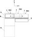
FIG. 1 is a front view schematically showing a
<記録装置>
記録装置1Aは、記録ユニット3、転写ユニット4および周辺ユニット5A〜5D、および、供給ユニット6を含む。<Recording device>
The
<記録ユニット>
記録ユニット3は、複数の記録ヘッド30と、キャリッジ31とを含む。図1と図2を参照する。図2は記録ユニット3の斜視図である。記録ヘッド30は、転写体(中間転写体)2に液体インクを吐出し、転写体2上に記録画像のインク像を形成する。<Recording unit>
The
本実施形態の場合、各記録ヘッド30は、Y方向に延設されたフルラインヘッドであり、使用可能な最大サイズの記録媒体の画像記録領域の幅分をカバーする範囲にノズルが配列されている。記録ヘッド30は、その下面に、ノズルが開口したインク吐出面を有しており、インク吐出面は、微小隙間(例えば数mm)を介して転写体2の表面と対向している。本実施形態の場合、転写体2は円軌道上を循環的に移動する構成であるため、複数の記録ヘッド30は、放射状に配置されている。 In the case of the present embodiment, each
各ノズルには吐出素子が設けられている。吐出素子は、例えば、ノズル内に圧力を発生させてノズル内のインクを吐出させる素子であり、公知のインクジェットプリンタのインクジェットヘッドの技術が適用可能である。吐出素子としては、例えば電気熱変換体によりインクに膜沸騰を生じさせ気泡を形成することでインクを吐出する素子、電気機械変換体(ピエゾ素子)によってインクを吐出する素子、静電気を利用してインクを吐出する素子等が挙げられる。高速で高密度の記録の観点からは電気熱変換体を利用した吐出素子を用いることができる。 Each nozzle is provided with an ejection element. The ejection element is, for example, an element that generates pressure in the nozzle and ejects ink in the nozzle, and an inkjet head technique of a known inkjet printer is applicable. As an ejection element, for example, an element that ejects ink by causing film boiling in the ink by an electrothermal transducer and forming bubbles, an element that ejects ink by an electromechanical transducer (piezo element), or using static electricity Examples include an element that ejects ink. From the viewpoint of high-speed and high-density recording, an ejection element using an electrothermal transducer can be used.
本実施形態の場合、記録ヘッド30は、9つ設けられている。各記録ヘッド30は、互いに異なる種類のインクを吐出する。異なる種類のインクとは、例えば、色材が異なるインクであり、イエロインク、マゼンタインク、シアンインク、ブラックインク等のインクである。1つの記録ヘッド30は1種類のインクを吐出するが、1つの記録ヘッド30が複数種類のインクを吐出する構成であってもよい。このように複数の記録ヘッド30を設けた場合、そのうちの一部が色材を含まないインク(例えばクリアインク)を吐出してもよい。 In the present embodiment, nine recording heads 30 are provided. Each
キャリッジ31は、複数の記録ヘッド30を支持する。各記録ヘッド30は、インク吐出面側の端部がキャリッジ31に固定されている。これにより、インク吐出面と転写体2との表面の隙間をより精密に維持することができる。キャリッジ31は、案内部材RLの案内によって、記録ヘッド30を搭載しつつ変位可能に構成されている。本実施形態の場合、案内部材RLは、Y方向に延設されたレール部材であり、X方向に離間して一対設けられている。キャリッジ31のX方向の各側部にはスライド部32が設けられている。スライド部32は案内部材RLと係合し、案内部材RLに沿ってY方向にスライドする。 The
図3は記録ユニット3の変位態様を示しており、記録システム1の右側面を模式的に示した図である。記録システム1の後部には回復ユニット12が設けられている。回復ユニット12は記録ヘッド30の吐出性能を回復する機構を有する。そのような機構としては、例えば、記録ヘッド30のインク吐出面をキャッピングするキャップ機構、インク吐出面をワイピングするワイパ機構、インク吐出面から記録ヘッド30内のインクを負圧吸引する吸引機構を挙げることができる。 FIG. 3 shows a displacement mode of the
案内部材RLは、転写体2の側方から回復ユニット12に渡って延設されている。記録ユニット3は、案内部材RLの案内により、実線で記録ユニット3を示した吐出位置POS1と、破線で記録ユニット3を示した回復位置POS3との間で変位可能であり、不図示の駆動機構により移動される。 The guide member RL extends from the side of the
吐出位置POS1は、記録ユニット3が転写体2にインクを吐出する位置であり、記録ヘッド30のインク吐出面が転写体2の表面に対向する位置である。回復位置POS3は、吐出位置POS1から退避した位置であり、記録ユニット3が回復ユニット12上に位置する位置である。回復ユニット12は記録ユニット3が回復位置POS3に位置した場合に、記録ヘッド30に対する回復処理を実行可能である。本実施形態の場合、記録ユニット3が回復位置POS3に到達する前の移動途中においても回復処理を実行可能である。吐出位置POS1と回復位置POS3の間には予備回復位置POS2があり、回復ユニット12は記録ヘッド30が吐出位置POS1から回復位置POS3へ移動中に、予備回復位置POS2において記録ヘッド30に対する予備的な回復処理を実行可能である。 The ejection position POS1 is a position where the
<転写ユニット>
図1を参照して転写ユニット4について説明する。転写ユニット4は、転写胴41と圧胴42とを含む。これらの胴は、Y方向の回転軸周りに回転する回転体であり、円筒形状の外周面を有している。図1において、転写胴41および圧胴42の各図形内に示した矢印は、これらの回転方向を示しており、転写胴41は時計回りに、圧胴42は反時計回りに回転する。<Transfer unit>
The
転写胴41は、その外周面に転写体2を支持する支持体である。転写体2は、転写胴41の外周面上に、周方向に連続的にあるいは間欠的に設けられる。連続的に設けられる場合、転写体2は無端の帯状に形成される。間欠的に設けられる場合、転写体2は、有端の帯状に複数のセグメントに分けて形成され、各セグメントは転写胴41の外周面に等ピッチで円弧状に配置することができる。 The
転写胴41の回転により、転写体2は円軌道上を循環的に移動する。転写胴41の回転位相により、転写体2の位置は、吐出前処理領域R1、吐出領域R2、吐出後処理領域R3およびR4、転写領域R5、転写後処理領域R6に区別することができる。転写体2はこれらの領域を循環的に通過する。 As the
吐出前処理領域R1は、記録ユニット3によるインクの吐出前に転写体2に対する前処理を行う領域であり、周辺ユニット5Aによる処理が行われる領域である。本実施形態の場合、反応液が付与される。吐出領域R2は記録ユニット3が転写体2にインクを吐出してインク像を形成する形成領域である。吐出後処理領域R3およびR4はインクの吐出後にインク像に対する処理を行う処理領域であり、吐出後処理領域R3は周辺ユニット5Bによる処理が行われる領域であり、吐出後処理領域R4は周辺ユニット5Cによる処理が行われる領域である。転写領域R5は転写ユニット4により転写体2上のインク像が記録媒体Pに転写される領域である。転写後処理領域R6は、転写後に転写体2に対する後処理を行う領域であり、周辺ユニット5Dによる処理が行われる領域である。 The pre-ejection processing region R1 is a region where pre-processing is performed on the
本実施形態の場合、吐出領域R2は、一定の区間を有する領域である。他の領域R1、R3〜R6は、吐出領域R2に比べるとその区間は狭い。時計の文字盤に喩えると、本実施形態の場合、吐出前処理領域R1は概ね10時の位置であり、吐出領域R2は概ね11時から1時の範囲であり、吐出後処理領域R3は概ね2時の位置であり、吐出後処理領域R4は概ね4時の位置である。転写領域R5は概ね6時の位置であり、転写後処理領域R6は概ね8時の領域である。 In the case of the present embodiment, the ejection region R2 is a region having a certain section. The other regions R1, R3 to R6 are narrower than the discharge region R2. In the case of the present embodiment, in the case of this embodiment, the pre-discharge processing region R1 is approximately at 10 o'clock, the discharge region R2 is approximately from 11:00 to 1 o'clock, and the post-discharge processing region R3 is approximately It is the 2 o'clock position, and the post-discharge processing region R4 is approximately the 4 o'clock position. The transfer region R5 is approximately 6 o'clock and the post-transfer processing region R6 is approximately 8 o'clock.
転写体2は、単層から構成してもよいが、複数層の積層体としてもよい。複数層で構成する場合、例えば、表面層、弾性層、圧縮層の三層を含んでもよい。表面層はインク像が形成される画像形成面を有する最外層である。圧縮層を設けることで、圧縮層が変形を吸収し、局所的な圧力変動に対してその変動を分散し、高速記録時においても転写性を維持することができる。弾性層は表面層と圧縮層との間の層である。 The
表面層の材料としては、樹脂、セラミック等各種材料を適宜用いることができるが、耐久性等の点で圧縮弾性率の高い材料を用いることができる。具体的には、アクリル樹脂、アクリルシリコーン樹脂、フッ素含有樹脂、加水分解性有機ケイ素化合物を縮合して得られる縮合物等が挙げられる。表面層には、反応液の濡れ性、画像の転写性等を向上させるために、表面処理を施して用いてもよい。表面処理としては、フレーム処理、コロナ処理、プラズマ処理、研磨処理、粗化処理、活性エネルギー線照射処理、オゾン処理、界面活性剤処理、シランカップリング処理などが挙げられる。これらを複数組み合わせてもよい。また、表面層に任意の表面形状を設けることもできる。 As a material for the surface layer, various materials such as a resin and a ceramic can be used as appropriate, but a material having a high compression elastic modulus can be used in terms of durability and the like. Specific examples include condensates obtained by condensing acrylic resins, acrylic silicone resins, fluorine-containing resins, and hydrolyzable organosilicon compounds. The surface layer may be used after being subjected to a surface treatment in order to improve the wettability of the reaction solution, the image transferability, and the like. Examples of the surface treatment include flame treatment, corona treatment, plasma treatment, polishing treatment, roughening treatment, active energy ray irradiation treatment, ozone treatment, surfactant treatment, and silane coupling treatment. A plurality of these may be combined. Moreover, arbitrary surface shapes can also be provided in the surface layer.
圧縮層の材料としては、例えばアクリロニトリル−ブタジエンゴム、アクリルゴム、クロロプレンゴム、ウレタンゴム、シリコーンゴム等が挙げられる。このようなゴム材料の成形時には、所定量の加硫剤、加硫促進剤等を配合し、さらに発泡剤、中空微粒子或いは食塩等の充填剤を必要に応じて配合し、多孔質のゴム材料としてもよい。これにより、様々な圧力変動に対して気泡部分が体積変化を伴って圧縮されるため、圧縮方向以外への変形が小さく、より安定した転写性、耐久性を得ることができる。多孔質のゴム材料としては、各気孔が互いに連続した連続気孔構造のものと、各気孔がそれぞれ独立した独立気孔構造のものがあるが、いずれの構造であってもよく、これらの構造を併用してもよい。 Examples of the material for the compression layer include acrylonitrile-butadiene rubber, acrylic rubber, chloroprene rubber, urethane rubber, and silicone rubber. At the time of molding such a rubber material, a predetermined amount of a vulcanizing agent, a vulcanization accelerator and the like are blended, and further a filler such as a foaming agent, hollow fine particles or salt is blended as necessary, and a porous rubber material It is good. Thereby, since the bubble part is compressed with a volume change with respect to various pressure fluctuations, deformation in the direction other than the compression direction is small, and more stable transferability and durability can be obtained. There are two types of porous rubber materials: one with a continuous pore structure in which each pore is continuous and the other with an independent pore structure in which each pore is independent. May be.
弾性層の部材としては、樹脂、セラミック等、各種材料を適宜用いることができる。加工特性等の点で、各種エラストマー材料、ゴム材料を用いることができる。具体的には、例えばフルオロシリコーンゴム、フェニルシリコーンゴム、フッ素ゴム、クロロプレンゴム、ウレタンゴム、ニトリルゴム等が挙げられる。また、エチレンプロピレンゴム、天然ゴム、スチレンゴム、イソプレンゴム、ブタジエンゴム、エチレン/プロピレン/ブタジエンのコポリマー、ニトリルブタジエンゴム等が挙げられる。特に、シリコーンゴム、フルオロシリコーンゴム、フェニルシリコーンゴムは、圧縮永久ひずみが小さいため、寸法安定性、耐久性の面で有利である。また、温度による弾性率の変化が小さく、転写性の点でも有利である。 As the member of the elastic layer, various materials such as resin and ceramic can be used as appropriate. Various elastomer materials and rubber materials can be used in terms of processing characteristics. Specific examples include fluorosilicone rubber, phenylsilicone rubber, fluororubber, chloroprene rubber, urethane rubber, and nitrile rubber. Further, ethylene propylene rubber, natural rubber, styrene rubber, isoprene rubber, butadiene rubber, ethylene / propylene / butadiene copolymer, nitrile butadiene rubber and the like can be mentioned. In particular, silicone rubber, fluorosilicone rubber, and phenyl silicone rubber are advantageous in terms of dimensional stability and durability because they have a small compression set. Further, the change in elastic modulus with temperature is small, which is advantageous in terms of transferability.
表面層と弾性層の間、弾性層と圧縮層の間には、これらを固定するために各種接着剤や両面テープを用いることもできる。また、転写体2は、転写胴41に装着する際の横伸びの抑制や、コシを保つために圧縮弾性率が高い補強層を含んでもよい。また、織布を補強層としてもよい。転写体2は前記材質による各層を任意に組み合わせて作製することができる。 Various adhesives and double-sided tapes can be used between the surface layer and the elastic layer and between the elastic layer and the compression layer in order to fix them. Further, the
圧胴42は、その外周面が転写体2に圧接される。圧胴42の外周面には、記録媒体Pの先端部を保持するグリップ機構が少なくとも一つ設けられている。グリップ機構は圧胴42の周方向に離間して複数設けてもよい。記録媒体Pは圧胴42の外周面に密接して搬送されつつ、圧胴42と転写体2とのニップ部を通過するときに、転写体2上のインク像が転写される。 The outer surface of the
転写胴41と圧胴42とを駆動するモータ等の駆動源は、これらに共通とし、歯車機構等の伝達機構により、駆動力を分配することができる。 A driving source such as a motor for driving the
<周辺ユニット>
周辺ユニット5A〜5Dは転写胴41の周囲に配置されている。本実施形態の場合、周辺ユニット5A〜5Dは、順に、付与ユニット、吸収ユニット、加熱ユニット、清掃ユニットである。<Peripheral unit>
The peripheral units 5 </ b> A to 5 </ b> D are arranged around the
付与ユニット5Aは、記録ユニット3によるインクの吐出前に、転写体2上に反応液を付与する機構である。反応液は、インクを高粘度化する成分を含有する液体である。ここで、インクの高粘度化とは、インクを構成している色材や樹脂等がインクを高粘度化する成分と接触することによって化学的に反応し、あるいは物理的に吸着し、これによってインクの粘度の上昇が認められることである。このインクの高粘度化には、インク全体の粘度上昇が認められる場合のみならず、色材や樹脂等のインクを構成する成分の一部が凝集することにより局所的に粘度の上昇が生じる場合も含まれる。 The applying unit 5 </ b> A is a mechanism that applies a reaction liquid onto the
インクを高粘度化する成分は、金属イオン、高分子凝集剤など、特に制限はないが、インクのpH変化を引き起こして、インク中の色材を凝集させる物質を用いることができ、有機酸を用いることができる。反応液の付与機構としては、例えば、ローラ、記録ヘッド、ダイコーティング装置(ダイコータ)、ブレードコーティング装置(ブレードコータ)などが挙げられる。転写体2に対するインクの吐出前に反応液を転写体2に付与しておくと、転写体2に達したインクを直ちに定着させることができる。これにより、隣接するインク同士が混ざり合うブリーディングを抑制することができる。 There are no particular restrictions on the components that increase the viscosity of the ink, such as metal ions and polymer flocculants, but substances that cause the pH change of the ink and cause the colorant in the ink to aggregate can be used. Can be used. Examples of the reaction liquid application mechanism include a roller, a recording head, a die coating apparatus (die coater), a blade coating apparatus (blade coater), and the like. If the reaction liquid is applied to the
吸収ユニット5Bは、転写前に、転写体2上のインク像から液体成分を吸収する機構である。インク像の液体成分を減少させることで、記録媒体Pに記録される画像のにじみ等を抑制することができる。液体成分の減少を異なる視点で説明すれば、転写体2上のインク像を構成するインクを濃縮すると表現することもできる。インクを濃縮するとは、インクに含まれる液体成分が減少することによって、インクに含まれる色材や樹脂といった固形分の液体成分に対する含有割合が増加することを意味する。 The
吸収ユニット5Bは、例えば、インク像に接触してインク像の液体成分の量を減少させる液吸収部材を含む。液吸収部材はローラの外周面に形成されてもよいし、液吸収部材が無端のシート状に形成され、循環的に走行されるものでもよい。インク像の保護の点で、液吸収部材の移動速度を転写体2の周速度と同じにして液吸収部材を転写体2と同期して移動させてもよい。 The
液吸収部材は、インク像に接触する多孔質体を含んでもよい。液吸収部材へのインク固形分付着を抑制するため、インク像に接触する面の多孔質体の孔径は、10μm以下であってもよい。ここで、孔径とは平均直径のことを示し、公知の手段、例えば水銀圧入法や、窒素吸着法、SEM画像観察等で測定可能である。なお、液体成分は、一定の形を有さず、流動性があり、ほぼ一定の体積を有するものであれば、特に限定されるものではない。例えば、インクや反応液に含まれる水や有機溶媒等が液体成分として挙げられる 。 The liquid absorbing member may include a porous body that contacts the ink image. In order to suppress ink solid matter adhesion to the liquid absorbing member, the pore diameter of the porous body on the surface in contact with the ink image may be 10 μm or less. Here, the pore diameter means an average diameter, which can be measured by a known means such as a mercury intrusion method, a nitrogen adsorption method, or an SEM image observation. The liquid component is not particularly limited as long as it does not have a certain shape, has fluidity, and has a substantially constant volume. For example, water or an organic solvent contained in the ink or the reaction liquid can be used as the liquid component.
加熱ユニット5Cは、転写前に、転写体2上のインク像を加熱する機構である。インク像を加熱することで、インク像中の樹脂が溶融し、記録媒体Pへの転写性を向上する。加熱温度は、樹脂の最低造膜温度(MFT)以上とすることができる。MFTは一般的に知られている手法、例えばJIS K 6828−2:2003や、ISO2115:1996に準拠した各装置で測定することが可能である。転写性及び画像の堅牢性の観点から、MFTよりも10℃以上高い温度で加熱してもよく、更に、20℃以上高い温度で加熱してもよい。加熱ユニット5Cは、例えば、赤外線等の各種ランプ、温風ファン等、公知の加熱デバイスを用いることができる。加熱効率の点で、赤外線ヒータを用いることができる。 The
清掃ユニット5Dは、転写後に転写体2上を清掃する機構である。清掃ユニット5Dは、転写体2上に残留したインクや、転写体2上のごみ等を除去する。清掃ユニット5Dは、例えば、多孔質部材を転写体2に接触させる方式、ブラシで転写体2の表面を擦る方式、ブレードで転写体2の表面をかきとる方式等の公知の方式を適宜用いることができる。また、清掃に用いる清掃部材は、ローラ形状、ウェブ形状等、公知の形状を用いることができる。 The
以上の通り、本実施形態では、付与ユニット5A、吸収ユニット5B、加熱ユニット5C、清掃ユニット5Dを周辺ユニットとして備えるが、これらの一部のユニットに転写体2の冷却機能を付与するか、あるいは、冷却ユニットを追加してもよい。本実施形態では、加熱ユニット5Cの熱により転写体2の温度が上昇する場合がある。記録ユニット3により転写体2にインクを吐出した後、インク像がインクの主溶剤である水の沸点を超えると、吸収ユニット5Bによる液体成分の吸収性能が低下する場合がある。吐出されたインクが水の沸点未満に維持されるように転写体2を冷却することで、液体成分の吸収性能を維持することができる。 As described above, in the present embodiment, the providing
冷却ユニットは、転写体2に送風する送風機構や、転写体2に部材(例えばローラ)を接触させ、この部材を空冷または水冷で冷却する機構であってもよい。また、清掃ユニット5Dの清掃部材を冷却する機構であってもよい。冷却タイミングは、転写後、反応液の付与前までの期間であってもよい。 The cooling unit may be a blower mechanism that blows air to the
<供給ユニット>
供給ユニット6は、記録ユニット3の各記録ヘッド30にインクを供給する機構である。供給ユニット6は記録システム1の後部側に設けられていてもよい。供給ユニット6は、インクの種類毎に、インクを貯留する貯留部TKを備える。貯留部TKは、メインタンクとサブタンクとによって構成されてもよい。各貯留部TKと各記録ヘッド30とは流路6aで連通し、貯留部TKから記録ヘッド30へインクが供給される。流路6aは、貯留部TKと記録ヘッド30との間でインクを循環させる流路であってもよく、供給ユニット6はインクを循環させるポンプ等を備えてもよい。流路6aの途中または貯留部TKには、インク中の気泡を脱気する脱気機構を設けてもよい。流路6aの途中または貯留部TKには、インクの液圧と大気圧との調整を行うバルブを設けてもよい。貯留部TK内のインク液面が、記録ヘッド30のインク吐出面よりも低い位置となるように、貯留部TKと記録ヘッド30のZ方向の高さが設計されてもよい。<Supply unit>
The supply unit 6 is a mechanism that supplies ink to each
<搬送装置>
搬送装置1Bは、記録媒体Pを転写ユニット4へ給送し、インク像が転写された記録物P’を転写ユニット4から排出する装置である。搬送装置1Bは、給送ユニット7、複数の搬送胴8、8a、二つのスプロケット8b、チェーン8cおよび回収ユニット8dを含む。図1において、搬送装置1Bの各構成の図形の内側の矢印はその構成の回転方向を示し、外側の矢印は記録媒体Pまたは記録物P’の搬送経路を示している。記録媒体Pは給送ユニット7から転写ユニット4へ搬送され、記録物P’は転写ユニット4から回収ユニット8dへ搬送される。給送ユニット7側を搬送方向で上流側と呼び、回収ユニット8d側を下流側と呼ぶ場合がある。<Conveyor>
The
給送ユニット7は、複数の記録媒体Pが積載される積載部を含むと共に、積載部から一枚ずつ記録媒体Pを、最上流の搬送胴8に給送する給送機構を含む。各搬送胴8、8aはY方向の回転軸周りに回転する回転体であり、円筒形状の外周面を有している。各搬送胴8、8aの外周面には、記録媒体P(または記録物P’)の先端部を保持するグリップ機構が少なくとも一つ設けられている。各グリップ機構は、隣接する搬送胴間で記録媒体Pを受け渡されるように、その把持動作および解除動作が制御される。 The
二つの搬送胴8aは、記録媒体Pの反転用の搬送胴である。記録媒体Pを両面記録する場合、表面への転写後に、圧胴42から下流側に隣接する搬送胴8へ記録媒体Pを渡さずに、搬送胴8aに渡す。記録媒体Pは、二つの搬送胴8aを経由して表裏が反転され、圧胴42の上流側の搬送胴8を経由して再び圧胴42へ渡される。これにより、記録媒体Pの裏面が転写胴41に面することになり、裏面にインク像が転写される。 The two
チェーン8cは、二つのスプロケット8b間に巻き回されている。二つのスプロケット8bの一方は駆動スプロケットであり他方は従動スプロケットである。駆動スプロケットの回転によりチェーン8cが循環的に走行する。チェーン8cには、その長手方向に離間して複数のグリップ機構が設けられている。グリップ機構は、記録物P’の端部を把持する。下流端に位置する搬送胴8からチェーン8cのグリップ機構に記録物P’が渡され、グリップ機構に把持された記録物P’はチェーン8cの走行により回収ユニット8dへ搬送され、把持が解除される。これにより記録物P’が回収ユニット8d内に積載される。 The
<後処理ユニット>
搬送装置1Bには、後処理ユニット10A、10Bが設けられている。後処理ユニット10A、10Bは転写ユニット4よりも下流側に配置され、記録物P’に対して後処理を行う機構である。後処理ユニット10Aは、記録物P’の表面に対する処理を行い、後処理ユニット10Bは、記録物P’の裏面に対する処理を行う。処理の内容としては、例えば、記録物P’の画像記録面に、画像の保護や艶出し等を目的としたコーティングを挙げることができる。コーティングの内容としては、例えば、液体の塗布、シートの溶着、ラミネート等を挙げることができる。<Post-processing unit>
The
<検査ユニット>
搬送装置1Bには、検査ユニット9A、9Bが設けられている。検査ユニット9A、9Bは転写ユニット4よりも下流側に配置され、記録物P’の検査を行う機構である。<Inspection unit>
本実施形態の場合、検査ユニット9Aは、記録物P’に記録された画像を撮影する撮影装置であり、例えば、CCDセンサやCMOSセンサ等の撮像素子を含む。検査ユニット9Aは、連続的に行われる記録動作中に、記録画像を撮影する。検査ユニット9Aが撮影した画像に基づいて、記録画像の色味などの経時変化を確認し、画像データあるいは記録データの補正の可否を判断することができる。本実施形態の場合、検査ユニット9Aは、圧胴42の外周面に撮像範囲が設定されており、転写直後の記録画像を部分的に撮影可能に配置されている。検査ユニット9Aにより全ての記録画像の検査を行ってもよいし、所定数毎に検査を行ってもよい。 In the case of the present embodiment, the
本実施形態の場合、検査ユニット9Bも、記録物P’に記録された画像を撮影する撮影装置であり、例えば、CCDセンサやCMOSセンサ等の撮像素子を含む。検査ユニット9Bは、テスト記録動作において記録画像を撮影する。検査ユニット9Bは、記録画像の全体を撮影し、検査ユニット9Bが撮影した画像に基づいて、記録データに関する各種の補正の基本設定を行うことができる。本実施形態の場合、チェーン8cで搬送される記録物P’を撮影する位置に配置されている。検査ユニット9Bにより記録画像を撮影する場合、チェーン8cの走行を一時的に停止して、その全体を撮影する。検査ユニット9Bは、記録物P’上を走査するスキャナであってもよい。 In the case of the present embodiment, the
<制御ユニット>
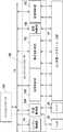
次に、記録システム1の制御ユニットについて説明する。図4および図5は記録システム1の制御ユニット13のブロック図である。制御ユニット13は、上位装置(DFE)HC2に通信可能に接続され、また、上位装置HC2はホスト装置HC1に通信可能に接続される。<Control unit>
Next, the control unit of the
ホスト装置HC1は、例えば、情報処理装置であるPC(Personal Computer)であってもよいし、サーバ装置であってもよい。また、ホスト装置HC1と上位装置HC2間の通信方法については、有線/無線のいずれでもよく、特に限定するものではない。 The host device HC1 may be, for example, a PC (Personal Computer) that is an information processing device or a server device. Further, the communication method between the host device HC1 and the host device HC2 may be either wired or wireless, and is not particularly limited.
ホスト装置HC1では、記録画像の元になる原稿データが生成、あるいは保存される。ここでの原稿データは、例えば、文書ファイルや画像ファイル等の電子ファイルの形式で生成される。この原稿データは、上位装置HC2へ送信され、上位装置HC2では、受信した原稿データを制御ユニット13で利用可能なデータ形式(例えば、RGBで画像を表現するRGBデータ)に変換する。変換後のデータは、画像データとして上位装置HC2から制御ユニット13へ送信され、制御ユニット13は受信した画像データに基づき、記録動作を開始する。 In the host device HC1, document data that is the basis of a recorded image is generated or stored. The document data here is generated in the form of an electronic file such as a document file or an image file. This document data is transmitted to the host device HC2, and the host device HC2 converts the received document data into a data format that can be used by the control unit 13 (for example, RGB data representing an image in RGB). The converted data is transmitted as image data from the host device HC2 to the
本実施形態の場合、制御ユニット13は、メインコントローラ13Aと、エンジンコントローラ13Bとに大別される。メインコントローラ13Aは、処理部131、記憶部132、操作部133、画像処理部134、通信I/F(インタフェース)135、バッファ136および通信I/F137を含む。 In the case of the present embodiment, the
処理部131は、CPU等のプロセッサであり、記憶部132に記憶されたプログラムを実行し、メインコントローラ13A全体の制御を行う。記憶部132は、RAM、ROM、ハードディスク、SSD等の記憶デバイスであり、CPU(処理部)131が実行するプログラムや、データを格納し、また、CPU131にワークエリアを提供する。記憶部132のほか、外付けの記憶部が更に設けられていてもよい。操作部133は、例えば、タッチパネル、キーボード、マウス等の入力デバイスであり、ユーザの指示を受け付ける。操作部133は、例えば、入力部と表示部が一体となった構成であってもよい。なお、ユーザ操作は、操作部133を介した入力に限定するものではなく、例えば、ホスト装置HC1や上位装置HC2から指示を受け付けるような構成であってもよい。 The
画像処理部134は例えば画像処理プロセッサを有する電子回路である。バッファ136は、例えば、RAM、ハードディスクやSSDである。通信I/F135は上位装置HC2との通信を行い、通信I/F137はエンジンコントローラ13Bとの通信を行う。図4において破線矢印は、画像データの処理の流れを例示している。上位装置HC2から通信IF135を介して受信された画像データは、バッファ136に蓄積される。画像処理部134はバッファ136から画像データを読み出し、読み出した画像データに所定の画像処理を施して、再びバッファ136に格納する。バッファ136に格納された画像処理後の画像データは、プリントエンジンが用いる記録データとして、通信I/F137からエンジンコントローラ13Bへ送信される。 The
図5に示すように、エンジンコントローラ13Bは、制御部14、15A〜15Eを含み、記録システム1が備えるセンサ群およびアクチュエータ群16の検知結果の取得および駆動制御を行う。これらの各制御部は、CPU等のプロセッサ、RAMやROM等の記憶デバイス、外部デバイスとのインタフェースを含む。なお、制御部の区分けは一例であり、一部の制御を更に細分化した複数の制御部で実行してもよいし、逆に、複数の制御部を統合して、それらの制御内容を一つの制御部で行うように構成してもよい。 As shown in FIG. 5, the
エンジン制御部14は、エンジンコントローラ13Bの全体の制御を行う。記録制御部15Aは、メインコントローラ13Aから受信した記録データをラスタデータ等、記録ヘッド30の駆動に適したデータ形式に変換する。記録制御部15Aは、各記録ヘッド30の吐出制御を行う。 The
転写制御部15Bは、付与ユニット5Aの制御、吸収ユニット5Bの制御、加熱ユニット5Cの制御、及び清掃ユニット5Dの制御を行う。 The
信頼性制御部15Cは、供給ユニット6の制御、回復ユニット12の制御、および記録ユニット3を吐出位置POS1と回復位置POS3との間で移動させる駆動機構の制御を行う。 The
搬送制御部15Dは、転写ユニット4の駆動制御や、搬送装置1Bの制御を行う。検査制御部15Eは、検査ユニット9Bの制御、および検査ユニット9Aの制御を行う。 The conveyance control unit 15D performs drive control of the
センサ群およびアクチュエータ群16のうち、センサ群には、可動部の位置や速度を検知するセンサ、温度を検知するセンサ、撮像素子等が含まれる。アクチュエータ群にはモータ、電磁ソレノイド、電磁バルブ等が含まれる。 Of the sensor group and the
<動作例>
図6は記録動作の例を模式的に示す図である。転写胴41および圧胴42が回転されつつ、以下の各工程が循環的に行われる。状態ST1に示すように、始めに転写体2上に付与ユニット5Aから反応液Lが付与される。転写体2上の反応液Lが付与された部位は転写胴41の回転に伴って移動していく。反応液Lが付与された部位が記録ヘッド30の下に到達すると、状態ST2に示すように記録ヘッド30から転写体2にインクが吐出される。これによりインク像IMが形成される。その際、吐出されるインクが転写体2上の反応液Lと混ざりあうことで、色材の凝集が促進される。吐出されるインクは、供給ユニット6の貯留部TKから記録ヘッド30に供給される。<Operation example>
FIG. 6 is a diagram schematically showing an example of the recording operation. While the
転写体2上のインク像IMは転写体2の回転に伴って移動していく。インク像IMが吸収ユニット5Bに到達すると状態ST3に示すように吸収ユニット5Bによりインク像IMから液体成分が吸収される。インク像IMが加熱ユニット5Cに到達すると状態ST4に示すように加熱ユニット5Cによりインク像IMが加熱され、インク像IM中の樹脂が溶融し、インク像IMが造膜される。このようなインク像IMの形成に同期して、搬送装置1Bにより記録媒体Pが搬送される。 The ink image IM on the
状態ST5に示すように、インク像IMと記録媒体Pとが転写体2と圧胴42とのニップ部に到達し、記録媒体Pにインク像IMが転写され、記録物P’が製造される。ニップ部を通過すると、記録物P’に記録された画像が検査ユニット9Aにより撮影され、記録画像が検査される。記録物P’は搬送装置1Bにより回収ユニット8dへ搬送される。 As shown in the state ST5, the ink image IM and the recording medium P reach the nip portion between the
転写体2上のインク像IMが形成されていた部分は、清掃ユニット5Dに到達すると状態ST6に示すように清掃ユニット5Dにより清掃される。清掃後、転写体2は一回転したことになり、同様の手順で記録媒体Pへのインク像の転写が繰り返し行われる。上記の説明では理解を容易にするために、転写体2の一回転で一枚の記録媒体Pへのインク像IMの転写が一回行われるように説明したが、転写体2の一回転で複数枚の記録媒体Pへのインク像IMの転写が連続的に行うことができる。 When the ink image IM formed on the
このような記録動作を継続していくと各記録ヘッド30のメンテナンスが必要となる。 If such a recording operation is continued, maintenance of each
図7は各記録ヘッド30のメンテナンスの際の動作例を示している。状態ST11は、吐出位置POS1に記録ユニット3が位置している状態を示す。状態ST12は、記録ユニット3が予備回復位置POS2を通過している状態を示し、通過中に回復ユニット12により記録ユニット3の各記録ヘッド30の吐出性能を回復する処理が実行される。その後、状態ST13に示すように、記録ユニット3が回復位置POS3に位置した状態で、回復ユニット12により各記録ヘッド30の吐出性能を回復する処理が実行される。 FIG. 7 shows an example of operation during maintenance of each
次に以上のような構成の記録システムにおいて、転写体の周辺に配置された清掃ユニット5Dによって行われる清掃動作について説明する。 Next, the cleaning operation performed by the
<転写体と圧胴の詳細な説明>
図8は転写体と圧胴の詳細な構成と、両者の位置関係とを示す図である。<Detailed description of transfer body and impression cylinder>
FIG. 8 is a diagram showing the detailed configuration of the transfer body and the impression cylinder and the positional relationship between them.
図8に示されるように、転写体2は転写胴41により支持され転写胴41の外周に備えられる。この実施形態で、転写体2は、単層である構成であっても複数層の積層体である構成であっても、ゴムのような弾性があり記録媒体Pを圧胴42との間で挟持した場合に、その弾性力により記録媒体Pに印圧が発生するようになっている。そして、転写体2は位置P1を中心とする回転軸41aの周りに時計回りに回転する。一方、転写体2に対向して設けられる圧胴42は位置P2を中心とする回転軸42aの周りに反時計回りに回転する。 As shown in FIG. 8, the
図8に太線の点線で示されるように、転写体2が設けられた転写胴41と圧胴42とによりニップ部が形成され、このニップ部により記録媒体Pが挟持され、転写体2に形成された画像が記録媒体Pに対して転写される。 As shown by a thick dotted line in FIG. 8, a nip portion is formed by the
転写体2が設けられた転写胴41は半径r1の円筒形であり、圧胴42は半径r2の円筒形である。また、転写胴41と圧胴42との距離は、それぞれの回転軸の中心位置(軸芯)P1とP2の距離である軸間距離として定義され、この距離はLNGとして、図8では示されている。軸間距離LNGは、例えば、偏芯ベアリングなどを用いた軸間調整機構(後述)により調整可能である。回転軸41aはこの軸間調整機構に対して回転可能に固定される。回転軸42aは搬送装置1Bのフレームに回転可能に固定される。従って、この実施形態では、回転軸41aの位置が軸間調整機構により変化することにより、軸間距離LNGが調整される。 The
また、転写体2の外周面より少し離間した位置にレーザセンサ101が設けられ、レーザセンサ101からレーザ光を転写体2に対してその法線方向に照射することにより、半径r1の変化量(Δr1)をサブミクロン単位で検出することができる。一方、圧胴42の外周面より少し離間した位置にレーザセンサ102が設けられ、レーザセンサ102からレーザ光を圧胴42に対してその法線方向に照射することにより、半径r2の変化量(Δr2)をサブミクロン単位で検出することができる。ここで、最初の測定により検出される値が初期値とされる。 In addition, a
なお、半径r1、r2の変化を検出するためのセンサは、レーザセンサ以外のセンサを用いても良い。例えば、赤外線センサを用いて、転写体2と圧胴42の温度を計測し、その温度と転写体2と圧胴42の熱膨張率から半径r1、r2の変化を算出することもできる。 A sensor other than a laser sensor may be used as a sensor for detecting changes in the radii r1 and r2. For example, the temperature of the
図8の右側、点線で囲まれた領域には、転写胴41と圧胴42によるニップ部の拡大図が示されている。ここでは、記録媒体Pが圧胴42により搬送されてくる様子が示されている。実際のところ、転写胴41と圧胴42との間には間隔tがあるが、記録媒体Pの厚さdが間隔tより大きいと(d>t)、記録媒体Pの搬送に伴って、転写胴41に設けられた転写体2がその弾性により潰され、記録媒体Pに対して印圧(転写圧)が発生する。 In the area surrounded by the dotted line on the right side of FIG. 8, an enlarged view of the nip portion formed by the
従って、例えば、加熱ユニット5Cを動作させることによる記録システム1の温度の上昇などにより転写胴41や圧胴42が熱膨張(又は圧縮)すると、間隔tは変化する。この間隔tの変化は印圧(転写圧)の変化になる。 Therefore, for example, when the
このため、この実施形態では、2つのレーザセンサ101、102から所定時間間隔で転写体2、圧胴42それぞれに対してレーザ光を照射して、半径r1、r2の変位を測定する。間隔tの変化量(間隔変化量)Δtは、半径r1の変化量(Δr1)と半径r2の変化量(Δr2)の和(Δr1+Δr2)で表される。そして、変化量Δtを所定の閾値(TH)と比較し、変化量がその閾値を超えると、軸間調整機構を動作させて、間隔tが所定の範囲に収まるように制御する。 For this reason, in this embodiment, the laser beam is irradiated from the two
なお、記録媒体Pの種類によって、その厚さdが異なるので、記録媒体Pの種類に応じて適切な間隔tが設定されることが望ましい。そのために、記録システム1の利用者は、例えば、操作部133から厚さdの値または記録媒体Pの種類を設定すると良い。 Since the thickness d differs depending on the type of the recording medium P, it is desirable to set an appropriate interval t according to the type of the recording medium P. For this purpose, the user of the
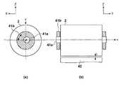
図9〜図11は軸間調整機構の概要を示す図である。図9に示す間隔tが図9〜図11の中で最も小さく、次いで図10、図11と軸間調整機構によって間隔tが大きくなる様子を示す。この実施形態における軸間調整機構は、円筒形状の偏芯ベアリングである軸支部41bによって構成される。 9 to 11 are views showing an outline of the inter-axis adjusting mechanism. The interval t shown in FIG. 9 is the smallest among FIGS. 9 to 11, and then the state where the interval t is increased by FIGS. 10 and 11 and the inter-axis adjusting mechanism is shown. The inter-axis adjusting mechanism in this embodiment is configured by a
図9(a)、図10(a)、図11(a)はそれぞれ、転写体2をY方向から見た図であり、回転軸41aと軸支部41bの相対的な位置関係を示す図である。図9(b)、図10(b)、図11(b)はそれぞれ、転写胴41と圧胴42をX方向から見た図であり、転写胴41と圧胴42との相対的な位置関係を示す図である。図9(a)と図9(b)は対応しており、図9(a)に示す回転軸41aと軸支部41bの位置関係のとき、図9(b)に示す転写胴41と圧胴42の位置関係が成り立つ。図10、図11も同様である。 FIGS. 9A, 10A, and 11A are views of the
図9(a)、図10(a)、図11(a)に示すように、円筒形状の軸支部41bは黒丸点●で示された回転軸41aの回転中心から偏芯して回転軸41aを支える構造となっている。軸支部41bが回転すると、軸支部41bの回転中心(白丸点○)と回転軸41aの中心位置P1との相対的な位置関係が変化する。従って、軸支部41bが回転すると、回転軸41aは、その偏芯の程度に従って、鉛直(z)方向に移動する。回転軸41aの移動に従って、転写胴41と圧胴42の軸間距離LNGは変更され、それに伴い間隔tが変化する。 As shown in FIGS. 9 (a), 10 (a), and 11 (a), the cylindrical
このように軸間調整機構として作用する軸支部41bを回転させることで軸間距離LNGを調整することができる。この回転により、図9〜図11に示すように、間隔tが異なる複数の状態を作り出すことができる。図9(a)では、軸支部41bの回転中心(白丸点○)が回転軸41aの中心位置P1よりも鉛直方向において高い位置に位置する。図10(a)では、軸支部41bの回転中心(白丸点○)と回転軸41aの中心位置P1が鉛直方向においてほぼ同じ高さに位置する。図11(a)では、軸支部41bの回転中心(白丸点○)が回転軸41aの中心位置P1よりも鉛直方向において低い位置に位置する。これらの位置関係に応じて、間隔tは図9(b)において最も小さく、図11(b)において最も大きくなっている。 Thus, the inter-shaft distance LNG can be adjusted by rotating the
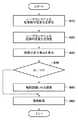
図12はこの実施形態に従う軸間調整処理を示すフローチャートである。 FIG. 12 is a flowchart showing the inter-axis adjustment process according to this embodiment.
図12には基本的な処理ステップが示されている。図12によれば、まず、ステップS10では、レーザセンサ101からレーザ光を転写体2に対してその径方向に照射し、半径r1の変化(Δr1)を測定する。次に、ステップS20では、レーザセンサ102からレーザ光を圧胴42に対してその径方向に照射することにより、半径r2の変化(Δr2)を測定する。 FIG. 12 shows the basic processing steps. According to FIG. 12, first, in step S10, a laser beam is irradiated from the
ステップS30では、測定された半径r1の変化量(Δr1)と半径r2の変化量(Δr2)とから間隔tの変化量Δtを算出する。そして、ステップS40では、変化量Δtが所定の閾値(TH)と比較する。ここで、Δt>THである場合、処理はステップS50に進み、軸間調整機構を動作させ軸支部41bを回動させて、軸間距離LNGが所定の範囲、即ち、間隔tが所定の範囲に収まるように制御する。これに対して、Δt≦THである場合、軸間調整機構を動作させることなく、この処理はステップS60に進む。 In step S30, the change amount Δt of the interval t is calculated from the measured change amount (Δr1) of the radius r1 and the change amount (Δr2) of the radius r2. In step S40, the change amount Δt is compared with a predetermined threshold value (TH). If Δt> TH, the process proceeds to step S50, the inter-axis adjustment mechanism is operated to rotate the
ステップS60では、軸間調整機構により間隔tが調整されるか、間隔tが検査され所定の範囲に収まっていることが確認された後に、記録媒体に画像を転写する。その後、処理は終了する。 In step S60, after the interval t is adjusted by the inter-axis adjusting mechanism or the interval t is inspected and confirmed to be within a predetermined range, the image is transferred to the recording medium. Thereafter, the process ends.
なお、この実施形態では、2つのレーザセンサ101、102から所定時間間隔で転写体2、圧胴42それぞれに対してレーザ光を照射して、半径r1、r2の変位量を測定するので、以上の処理は所定時間間隔で実行される。 In this embodiment, the laser beam is irradiated to each of the
なお、ステップS40において、変化量Δtと所定の閾値(TH)を比較する際には、レーザセンサ101、102によりn回の測定を行って、n個の変化量を求め、その平均値を算出し、その平均値を比較対象の変化量としても良い。これにより、測定毎に含まれる測定誤差を小さくし、より精確な変化量を求めることが可能になる。この場合には、ステップS10とステップS20それぞれにおいて、n回の測定が行われ、ステップS30では、測定されたn個の半径r1の変化量(Δr1)の半径r2の変化量(Δr2)のそれぞれに対する平均値が算出された後に、変化量Δtが算出される。 In step S40, when the amount of change Δt is compared with a predetermined threshold value (TH), the
また、レーザセンサ101、102それぞれの近傍に赤外線温度センサをさらに備え、これらのセンサにより、転写体2と圧胴42の表面温度を監視し、その温度変化を算出する。そして、その温度変化が所定の閾値を超えた時に、間隔tの変化量Δtが大きくなることが予想されると判断して、上記の処理を行って軸間調整を実行するようにしても良い。 In addition, an infrared temperature sensor is further provided in the vicinity of each of the
さらに、転写体2を備えた転写胴41が取り付けられるフレームに歪ゲージを取り付け、その歪ゲージからの出力によりフレームに生じた歪を算出し、その算出された歪で変化量Δtを補正するようにしても良い。或いは、そのフレームに温度センサを取り付け、その検出温度からの出力によりフレームに生じた歪を算出し、その算出された歪で変化量Δtを補正するようにしても良い。 Further, a strain gauge is attached to the frame to which the
なお、半径r1、r2の変化を検出するためのセンサは、レーザセンサ以外のセンサを用いても良い。例えば、赤外線温度センサを用いて、転写体2と圧胴42の表面温度を計測し、その温度と転写体2と圧胴42の熱膨張率から半径r1、r2の変化量を算出することもできる。 A sensor other than a laser sensor may be used as a sensor for detecting changes in the radii r1 and r2. For example, the surface temperature of the
従って以上説明した実施形態に従えば、転写胴と圧胴との間の間隔が調整されて、記録媒体に対する転写圧が適正になるように調整される。これにより、転写体から記録媒体に対して画像が適正に転写され、高品位な画像が記録される。 Therefore, according to the embodiment described above, the distance between the transfer cylinder and the impression cylinder is adjusted so that the transfer pressure on the recording medium is appropriate. As a result, the image is properly transferred from the transfer body to the recording medium, and a high-quality image is recorded.
上記実施形態では、記録ユニット3が複数の記録ヘッド30を有するが、一つの記録ヘッド30を有してもよい。記録ヘッド30はフルラインヘッドでなくてもよく、記録ヘッド30をY方向に走査させながらインク像を形成するシリアル方式であってもよい。 In the above embodiment, the
記録媒体Pの搬送機構は、ローラ対によって記録媒体Pを挟持して搬送する方式等、他の方式であってもよい。ローラ対によって記録媒体Pを搬送する方式等においては、記録媒体Pとしてロールシートを用いてもよく、転写後にロールシートをカットして記録物P’を製造してもよい。 The transport mechanism for the recording medium P may be another system such as a system for transporting the recording medium P while being sandwiched by a pair of rollers. In the method of conveying the recording medium P by a pair of rollers, a roll sheet may be used as the recording medium P, or the recorded material P ′ may be manufactured by cutting the roll sheet after transfer.
上記実施形態では、転写体2を転写胴41の外周面に設けたが、転写体2を無端の帯状に形成し、循環的に走行させる方式等、他の方式であってもよい。 In the above-described embodiment, the
また、本発明は上述の実施形態の1以上の機能を実現するプログラムをネットワーク又は記憶媒体を介してシステム又は装置に供給し、そのシステム又は装置のコンピュータにおける1つ以上のプロセッサがプログラムを読出し実行する処理でも実現可能である。また、1以上の機能を実現する回路(例えば、ASIC)によっても実現可能である。 Further, the present invention supplies a program that realizes one or more functions of the above-described embodiments to a system or apparatus via a network or a storage medium, and one or more processors in the computer of the system or apparatus read and execute the program This process can be realized. It can also be realized by a circuit (for example, ASIC) that realizes one or more functions.
2 転写体、3 記録ユニット、4 転写ユニット、5A 付与ユニット、
5B 吸収ユニット、5C 加熱ユニット、5D 清掃ユニット、30 記録ヘッド、
41 転写胴、41a 回転軸、41b 軸支部、42 圧胴、42a 回転軸、
101〜102 レーザセンサ、P 記録媒体2 transfer body, 3 recording unit, 4 transfer unit, 5A applying unit,
5B absorption unit, 5C heating unit, 5D cleaning unit, 30 recording head,
41 transfer cylinder, 41a rotating shaft, 41b shaft support, 42 impression cylinder, 42a rotating shaft,
101-102 Laser sensor, P recording medium
Claims (13)
Translated fromJapanese記録媒体を搬送する第2の回転体と、
前記第1の回転体と前記第2の回転体との間の間隔を取得する取得手段と、
前記取得手段により取得された前記間隔に基づいて、前記第1の回転体の回転軸と前記第2の回転体の回転軸との軸間距離を調整する調整手段と、
前記第2の回転体によって搬送される前記記録媒体に対して、前記第1の回転体に形成された前記画像を転写して記録する転写手段と、を有することを特徴とする記録装置。A first rotating body on which an image is formed by a recording head;
A second rotating body for conveying the recording medium;
Obtaining means for obtaining an interval between the first rotating body and the second rotating body;
Adjusting means for adjusting an inter-axis distance between the rotation axis of the first rotating body and the rotation axis of the second rotating body based on the interval acquired by the acquiring means;
A recording apparatus comprising: transfer means for transferring and recording the image formed on the first rotating body onto the recording medium conveyed by the second rotating body.
前記調整手段は、前記比較手段による比較の結果、前記間隔の変化が前記予め定められた閾値を超える場合に、前記軸間距離を調整することを特徴とする請求項1に記載の記録装置。Comparing means for comparing the interval acquired by the acquiring means with a predetermined threshold,
The recording apparatus according to claim 1, wherein the adjustment unit adjusts the inter-axis distance when the change in the interval exceeds the predetermined threshold as a result of comparison by the comparison unit.
前記第1の回転体の径を測定する第1の測定手段と、
前記第2の回転体の径を測定する第2の測定手段と、
前記第1の測定手段により測定された前記第1の回転体の径と、前記第2の測定手段により測定された前記第2の回転体の径とに基づいて、前記間隔を算出する算出手段とを含むことを特徴とする請求項1又は2に記載の記録装置。The acquisition means includes
First measuring means for measuring a diameter of the first rotating body;
Second measuring means for measuring a diameter of the second rotating body;
Calculation means for calculating the interval based on the diameter of the first rotating body measured by the first measuring means and the diameter of the second rotating body measured by the second measuring means. The recording apparatus according to claim 1, wherein the recording apparatus includes:
前記第2の測定手段は、前記第2の回転体の径の初期値からの第2の変化量を測定し、 前記算出手段は、前記第1の測定手段により測定された前記第1の変化量と、前記第2の測定手段により測定された前記第2の変化量、とに基づいて、前記間隔の間隔変化量を算出することを特徴とする請求項3に記載の記録装置。The first measuring means measures a first change amount from an initial value of the diameter of the first rotating body,
The second measuring means measures a second change amount from an initial value of the diameter of the second rotating body, and the calculating means is the first change measured by the first measuring means. 4. The recording apparatus according to claim 3, wherein an interval change amount of the interval is calculated based on an amount and the second change amount measured by the second measuring unit.
前記第2の測定手段は、前記第2の回転体の径方向にレーザ光を照射するレーザセンサであることを特徴とする請求項4に記載の記録装置。The first measuring means is a laser sensor that irradiates a laser beam in a radial direction of the first rotating body,
The recording apparatus according to claim 4, wherein the second measuring unit is a laser sensor that irradiates a laser beam in a radial direction of the second rotating body.
前記第2の測定手段は、前記第2の回転体の表面温度を測定する温度センサであり、
前記算出手段は、前記測定された前記第1の回転体と前記第2の回転体それぞれの表面温度と前記第1の回転体の前記第2の回転体それぞれの熱膨張率から、前記第1の回転体と前記第2の回転体の径の変化を算出することを特徴とする請求項4に記載の記録装置。The first measuring means is a temperature sensor for measuring a surface temperature of the first rotating body;
The second measuring means is a temperature sensor for measuring a surface temperature of the second rotating body;
The calculation means is configured to calculate the first rotational body based on the measured surface temperature of each of the first rotating body and the second rotating body and the coefficient of thermal expansion of each of the second rotating bodies of the first rotating body. The recording apparatus according to claim 4, wherein a change in a diameter of the rotating body and the second rotating body is calculated.
前記フレームの歪を検出する検出手段と、
前記検出手段によって検出された歪によって、前記取得手段により取得された前記間隔の変化を補正する補正手段とをさらに有することを特徴とする請求項4乃至6のいずれか1項に記載の記録装置。A frame for mounting the first rotating body;
Detecting means for detecting distortion of the frame;
The recording apparatus according to claim 4, further comprising a correction unit that corrects the change in the interval acquired by the acquisition unit based on the distortion detected by the detection unit. .
前記第1の回転体の第1の回転軸を軸支する円筒形状の回転可能な軸支部を含み、
前記軸支部は、前記第1の回転軸を前記軸支部の中心から偏芯して取り付けられており、
前記軸支部が回転することにより、前記軸間距離を調整することを特徴とする請求項8に記載の記録装置。The adjusting means includes
A cylindrical rotatable shaft supporting portion that supports the first rotating shaft of the first rotating body;
The shaft support is attached by decentering the first rotation shaft from the center of the shaft support,
The recording apparatus according to claim 8, wherein the inter-axis distance is adjusted by rotating the shaft support portion.
円筒形状の胴と、
該胴の外周面に備えられ、前記画像が形成される、弾性を有した転写体とを有し、
前記第1の回転体と前記第2の回転体とにより前記記録媒体を挟持する場合は、前記転写体が潰れることにより前記記録媒体に対して転写圧が発生することを特徴とする請求項1乃至9のいずれか1項に記載の記録装置。The first rotating body includes:
A cylindrical barrel;
An elastic transfer body provided on the outer peripheral surface of the cylinder, on which the image is formed,
The transfer pressure is generated on the recording medium when the recording medium is crushed when the recording medium is sandwiched between the first rotating body and the second rotating body. The recording apparatus according to any one of 1 to 9.
前記第1の回転体と前記第2の回転体との間隔を取得する取得工程と、
前記取得工程において取得された前記間隔に基づいて、前記第1の回転体の回転軸と前記第2の回転体の回転軸との軸間距離を調整する調整工程とを有することを特徴とする調整方法。A first rotating body on which an image is formed by a recording head, a second rotating body that conveys a recording medium, and the first rotating body with respect to the recording medium that is conveyed by the second rotating body And a transfer device for transferring and recording the image formed on the recording apparatus.
An acquisition step of acquiring an interval between the first rotating body and the second rotating body;
An adjustment step of adjusting an inter-axis distance between the rotation axis of the first rotation body and the rotation axis of the second rotation body based on the interval acquired in the acquisition step. Adjustment method.
Priority Applications (2)
| Application Number | Priority Date | Filing Date | Title |
|---|---|---|---|
| JP2017044225AJP6895775B2 (en) | 2017-03-08 | 2017-03-08 | Recording device and its adjustment method |
| US15/903,593US20180257369A1 (en) | 2017-03-08 | 2018-02-23 | Printing apparatus and adjustment method thereof |
Applications Claiming Priority (1)
| Application Number | Priority Date | Filing Date | Title |
|---|---|---|---|
| JP2017044225AJP6895775B2 (en) | 2017-03-08 | 2017-03-08 | Recording device and its adjustment method |
Publications (2)
| Publication Number | Publication Date |
|---|---|
| JP2018144435Atrue JP2018144435A (en) | 2018-09-20 |
| JP6895775B2 JP6895775B2 (en) | 2021-06-30 |
Family
ID=63446240
Family Applications (1)
| Application Number | Title | Priority Date | Filing Date |
|---|---|---|---|
| JP2017044225AExpired - Fee RelatedJP6895775B2 (en) | 2017-03-08 | 2017-03-08 | Recording device and its adjustment method |
Country Status (2)
| Country | Link |
|---|---|
| US (1) | US20180257369A1 (en) |
| JP (1) | JP6895775B2 (en) |
Cited By (2)
| Publication number | Priority date | Publication date | Assignee | Title |
|---|---|---|---|---|
| JP2022515804A (en)* | 2018-12-24 | 2022-02-22 | ランダ コーポレイション リミテッド | Digital printing system |
| JPWO2023008456A1 (en)* | 2021-07-30 | 2023-02-02 |
Families Citing this family (2)
| Publication number | Priority date | Publication date | Assignee | Title |
|---|---|---|---|---|
| JP2019018389A (en) | 2017-07-12 | 2019-02-07 | キヤノン株式会社 | Recording device |
| EP4264377A4 (en)* | 2021-02-02 | 2024-11-13 | Landa Corporation Ltd. | REDUCING DISTORTIONS IN PRINTED IMAGES |
Citations (9)
| Publication number | Priority date | Publication date | Assignee | Title |
|---|---|---|---|---|
| US20030103123A1 (en)* | 2001-12-04 | 2003-06-05 | Xerox Corporation | Continuous transfer and fusing application system |
| JP2005231165A (en)* | 2004-02-19 | 2005-09-02 | Shinano Kenshi Co Ltd | Offset printing machine |
| JP2005313505A (en)* | 2004-04-30 | 2005-11-10 | National Printing Bureau | Method and system for detecting pressure in intaglio printing press |
| JP2007276473A (en)* | 2006-04-03 | 2007-10-25 | Man Roland Druckmas Ag | Integrated quality regulation |
| JP2008212826A (en)* | 2007-03-05 | 2008-09-18 | Komori Corp | Method for adjusting contact pressure of liquid application machine and contact pressure adjustment device for liquid application machine |
| JP2010005860A (en)* | 2008-06-25 | 2010-01-14 | Seiko Epson Corp | Fluid jetting apparatus and fluid jetting method |
| JP2012240304A (en)* | 2011-05-19 | 2012-12-10 | Bridgestone Corp | Printing device and printing method |
| JP2014136427A (en)* | 2013-01-16 | 2014-07-28 | Xerox Corp | System and method for image surface preparation in aqueous inkjet printer |
| JP2015212077A (en)* | 2014-04-17 | 2015-11-26 | キヤノン株式会社 | Intermediate transfer member, image recording method, and image recording apparatus |
- 2017
- 2017-03-08JPJP2017044225Apatent/JP6895775B2/ennot_activeExpired - Fee Related
- 2018
- 2018-02-23USUS15/903,593patent/US20180257369A1/ennot_activeAbandoned
Patent Citations (9)
| Publication number | Priority date | Publication date | Assignee | Title |
|---|---|---|---|---|
| US20030103123A1 (en)* | 2001-12-04 | 2003-06-05 | Xerox Corporation | Continuous transfer and fusing application system |
| JP2005231165A (en)* | 2004-02-19 | 2005-09-02 | Shinano Kenshi Co Ltd | Offset printing machine |
| JP2005313505A (en)* | 2004-04-30 | 2005-11-10 | National Printing Bureau | Method and system for detecting pressure in intaglio printing press |
| JP2007276473A (en)* | 2006-04-03 | 2007-10-25 | Man Roland Druckmas Ag | Integrated quality regulation |
| JP2008212826A (en)* | 2007-03-05 | 2008-09-18 | Komori Corp | Method for adjusting contact pressure of liquid application machine and contact pressure adjustment device for liquid application machine |
| JP2010005860A (en)* | 2008-06-25 | 2010-01-14 | Seiko Epson Corp | Fluid jetting apparatus and fluid jetting method |
| JP2012240304A (en)* | 2011-05-19 | 2012-12-10 | Bridgestone Corp | Printing device and printing method |
| JP2014136427A (en)* | 2013-01-16 | 2014-07-28 | Xerox Corp | System and method for image surface preparation in aqueous inkjet printer |
| JP2015212077A (en)* | 2014-04-17 | 2015-11-26 | キヤノン株式会社 | Intermediate transfer member, image recording method, and image recording apparatus |
Cited By (5)
| Publication number | Priority date | Publication date | Assignee | Title |
|---|---|---|---|---|
| JP2022515804A (en)* | 2018-12-24 | 2022-02-22 | ランダ コーポレイション リミテッド | Digital printing system |
| JP7462648B2 (en) | 2018-12-24 | 2024-04-05 | ランダ コーポレイション リミテッド | Digital Printing System |
| US12122153B2 (en) | 2018-12-24 | 2024-10-22 | Landa Corporation Ltd. | Digital printing system |
| JPWO2023008456A1 (en)* | 2021-07-30 | 2023-02-02 | ||
| WO2023008456A1 (en)* | 2021-07-30 | 2023-02-02 | 株式会社デュプロ | Transfer apparatus |
Also Published As
| Publication number | Publication date |
|---|---|
| US20180257369A1 (en) | 2018-09-13 |
| JP6895775B2 (en) | 2021-06-30 |
Similar Documents
| Publication | Publication Date | Title |
|---|---|---|
| JP2019018388A (en) | Recording device | |
| JP2019014139A (en) | Inkjet recording device and temperature control method for the same | |
| JP7438263B2 (en) | Inkjet recording device and its temperature control method | |
| JP2019018389A (en) | Recording device | |
| US11318753B2 (en) | Control device and control method | |
| WO2018105215A1 (en) | Liquid absorbing apparatus, recording apparatus, recording method, and manufacturing method | |
| JP2018144358A (en) | Ink jet recording apparatus and recording method for the same | |
| JP2019014097A (en) | Recording device, liquid absorption device and control method | |
| JP6895775B2 (en) | Recording device and its adjustment method | |
| JP2020023111A (en) | Recording device and correction method therefor | |
| JP2018192678A (en) | Image processing apparatus, control method, and program | |
| JP2019142030A (en) | Inkjet recording device | |
| JP6824075B2 (en) | Recording device | |
| JP2018133742A (en) | Recording apparatus, inspection apparatus, and control method | |
| US10543678B2 (en) | Printing apparatus that specifies a region of a transfer member having a poor surface condition and prohibits printing in the region, and related print control method | |
| US20230264502A1 (en) | Printing apparatus, control method therefor, and storage medium | |
| JP6937624B2 (en) | Inkjet recording device and its recording method | |
| JP7242350B2 (en) | Ejection state detection method of liquid ejection head, liquid ejection apparatus, and control method thereof | |
| JP2020023113A (en) | Recording device and recording control method thereof | |
| JP2018149742A (en) | Cleaning device, recording device, and cleaning method | |
| JP2019018416A (en) | Recording device and recording control method of the same | |
| JP2020023106A (en) | Ink jet recording apparatus and control method thereof | |
| US12005715B2 (en) | Printing apparatus | |
| JP6970521B2 (en) | Recording device | |
| JP2018176527A (en) | Recording device |
Legal Events
| Date | Code | Title | Description |
|---|---|---|---|
| A621 | Written request for application examination | Free format text:JAPANESE INTERMEDIATE CODE: A621 Effective date:20200220 | |
| A977 | Report on retrieval | Free format text:JAPANESE INTERMEDIATE CODE: A971007 Effective date:20201208 | |
| A131 | Notification of reasons for refusal | Free format text:JAPANESE INTERMEDIATE CODE: A131 Effective date:20201211 | |
| RD01 | Notification of change of attorney | Free format text:JAPANESE INTERMEDIATE CODE: A7421 Effective date:20210103 | |
| A521 | Request for written amendment filed | Free format text:JAPANESE INTERMEDIATE CODE: A523 Effective date:20210113 | |
| A521 | Request for written amendment filed | Free format text:JAPANESE INTERMEDIATE CODE: A523 Effective date:20210122 | |
| TRDD | Decision of grant or rejection written | ||
| A01 | Written decision to grant a patent or to grant a registration (utility model) | Free format text:JAPANESE INTERMEDIATE CODE: A01 Effective date:20210510 | |
| A61 | First payment of annual fees (during grant procedure) | Free format text:JAPANESE INTERMEDIATE CODE: A61 Effective date:20210608 | |
| R151 | Written notification of patent or utility model registration | Ref document number:6895775 Country of ref document:JP Free format text:JAPANESE INTERMEDIATE CODE: R151 | |
| LAPS | Cancellation because of no payment of annual fees |