JP2018139744A - Top toy - Google Patents
Top toyDownload PDFInfo
- Publication number
- JP2018139744A JP2018139744AJP2017035083AJP2017035083AJP2018139744AJP 2018139744 AJP2018139744 AJP 2018139744AJP 2017035083 AJP2017035083 AJP 2017035083AJP 2017035083 AJP2017035083 AJP 2017035083AJP 2018139744 AJP2018139744 AJP 2018139744A
- Authority
- JP
- Japan
- Prior art keywords
- shaft
- guide groove
- top toy
- weight member
- rotation
- Prior art date
- Legal status (The legal status is an assumption and is not a legal conclusion. Google has not performed a legal analysis and makes no representation as to the accuracy of the status listed.)
- Granted
Links
Images


Classifications
- A—HUMAN NECESSITIES
- A63—SPORTS; GAMES; AMUSEMENTS
- A63F—CARD, BOARD, OR ROULETTE GAMES; INDOOR GAMES USING SMALL MOVING PLAYING BODIES; VIDEO GAMES; GAMES NOT OTHERWISE PROVIDED FOR
- A63F9/00—Games not otherwise provided for
- A63F9/16—Spinning-top games
- A—HUMAN NECESSITIES
- A63—SPORTS; GAMES; AMUSEMENTS
- A63H—TOYS, e.g. TOPS, DOLLS, HOOPS OR BUILDING BLOCKS
- A63H1/00—Tops
- A—HUMAN NECESSITIES
- A63—SPORTS; GAMES; AMUSEMENTS
- A63H—TOYS, e.g. TOPS, DOLLS, HOOPS OR BUILDING BLOCKS
- A63H1/00—Tops
- A63H1/02—Tops with detachable winding devices
Landscapes
- Engineering & Computer Science (AREA)
- Multimedia (AREA)
- Toys (AREA)
Abstract
Translated fromJapaneseDescription
Translated fromJapanese本発明はコマ玩具に関するものである。 The present invention relates to a top toy.
コマ玩具を使用したバトルゲームとして、コマ玩具を互いに衝突させ、その衝撃力によって相手方のコマ玩具の回転を止めたり、相手方のコマ玩具を弾き飛ばしたり、相手方のコマ玩具を分解させたりするものがある(例えば、特許文献1参照)。 As a battle game using top toys, the top toys collide with each other, and the impact force stops the opponent's top toy, flips the opponent's top toy, or disassembles the opponent's top toy. Yes (for example, see Patent Document 1).
例えば、特許文献1に開示されたコマ玩具では、胴体と軸部とを有し、軸部に対して胴体を一方向に相対回転させることで軸部の爪と胴体の爪とが係合する。そして、自分のコマ玩具が相手方のコマ玩具と衝突した場合に、胴体の回転が一時的に停止される一方で、軸部が回転をし続けることで、軸部と胴体とが他方向に相対回転されることにより、軸部の爪と胴体の爪との係合が解除され、軸部と胴体とが外れてコマ玩具が分解される。 For example, the top toy disclosed in
このようなコマ玩具では、胴体及び軸部の双方に互いに噛合又は接触する抵抗部材を設け、胴体と軸部とが外れる方向への相対回転を鈍らせて、軸部と胴体とが分解するまでの時間を長くし、バトルゲームを長く楽しめるようにしている。 In such a top toy, resistance members that mesh or contact each other are provided on both the body and the shaft part, and the relative rotation in the direction in which the body and the shaft part come off is blunted until the shaft part and the body are disassembled. The time is extended so that you can enjoy the battle game for a long time.
本発明は、他の方式によって胴体と軸部との分解時期を鈍らせることができる斬新なコマ玩具を提供することを目的とする。 An object of the present invention is to provide a novel top toy that can slow down the disassembly time of the body and the shaft by another method.
第1の手段は、
胴体と軸部とを有し、軸部に対して胴体を一方向に相対回転させることで前記軸部の係合部と前記胴体の係合部とが係合し、回転中に受ける衝撃によって前記軸部と前記胴体とが他方向に相対回転する力を受けたときに、前記軸部の係合部と前記胴体の係合部との係合が解除され、軸部と胴体とが外れて分解されるコマ玩具において、
前記軸部には、回転軸の周りに、回転軸心までの中心間距離が最も大きい第1位置から当該中心間距離が前記第1位置よりも小さい第2位置までを繋ぐ案内溝が形成され、前記案内溝には当該案内溝の内部を移動可能に重錘部材が収容され、回転速度が増大する際には前記重錘部材が前記第2位置側から前記第1位置側に移動し、前記軸部と前記胴体が前記他方向に相対回転するような衝撃を受けた際には前記重錘部材が前記第1位置側から第2位置側へ移動することを特徴とする。The first means is
The body has a body and a shaft, and by rotating the body relative to the shaft in one direction, the engaging portion of the shaft and the engaging portion of the body are engaged, and an impact received during rotation When the shaft and the body are subjected to a relative rotation force in the other direction, the engagement between the engagement portion of the shaft and the engagement portion of the body is released, and the shaft and the body are disengaged. In the top toy to be disassembled,
In the shaft portion, a guide groove is formed around the rotation axis to connect the first position having the largest center distance to the rotation axis to the second position having the center distance smaller than the first position. The weight member is accommodated in the guide groove so as to be movable in the guide groove, and when the rotation speed increases, the weight member moves from the second position side to the first position side, The weight member moves from the first position side to the second position side when receiving an impact such that the shaft portion and the body rotate relative to each other in the other direction.
第2の手段は、第1の手段において、前記案内溝は、前記中心間距離が前記第1位置から前記第2位置に向けて徐々に小さくなるように上面視で孤状に形成されていることを特徴とする。 According to a second means, in the first means, the guide groove is formed in an isolated shape in a top view so that the center-to-center distance gradually decreases from the first position toward the second position. It is characterized by that.
第3の手段は、前記第1の手段又は第2の手段において、前記案内溝は、上面視で前記第1位置を挟んで前記第2位置が配置されるように弓状に形成されていることを特徴とする。 According to a third means, in the first means or the second means, the guide groove is formed in an arcuate shape so that the second position is disposed across the first position in a top view. It is characterized by that.
第4の手段は、第1の手段から第3の手段のいずれか一の手段において、前記案内溝は、前記回転軸心を挟んで対峙する2箇所それぞれに形成されていることを特徴とする。 According to a fourth means, in any one of the first means to the third means, the guide groove is formed at each of two locations facing each other across the rotation axis. .
第1の手段によれば、コマ玩具が相手方のコマ玩具と衝突した際に、その衝撃によって重錘部材が慣性力で案内溝の第1位置側から第2位置に移動する。案内溝において第2位置は第1位置よりもコマ玩具の回転軸心までの中心間距離が小さいので、重錘部材が第2位置側へ移動すると、軸部の回転エネルギや回転力が小さくなる。その結果、胴体と軸部とが外れる方向への相対回転を鈍らせ、分解までの時間を長くすることができる。 According to the first means, when the top toy collides with the other top toy, the weight member is moved from the first position side of the guide groove to the second position by inertia force by the impact. In the guide groove, the distance between the centers of the second position and the rotational axis of the top toy is smaller than that of the first position. Therefore, when the weight member moves toward the second position, the rotational energy and rotational force of the shaft portion are reduced. . As a result, the relative rotation in the direction in which the body and the shaft part come off can be blunted, and the time until disassembly can be extended.
第2の手段によれば、案内溝の中心と回転軸心までの中心間距離が第1位置側から第2位置側に向けて徐々に小さくなるように案内溝が上面視で孤状に形成されているので、外力を受けた際に重錘部材が案内溝内を円滑に移動することとなる。 According to the second means, the guide groove is formed in an isolated shape in a top view so that the distance between the center of the guide groove and the center of rotation is gradually reduced from the first position side toward the second position side. Therefore, the weight member smoothly moves in the guide groove when receiving an external force.
第3の手段よれば、軸部が両回転用に適用できるため、1つのコマ玩具が両回転用の場合に有効であるとともに、胴体の付け替えによって他の逆回転用コマ玩具にも使用できることから、有用性の高いコマ玩具が実現できる。 According to the third means, since the shaft portion can be applied to both rotations, it is effective when one top toy is used for both rotations and can be used for other reverse rotation top toys by changing the body. Highly useful top toy can be realized.
第4の手段によれば、案内溝が回転軸心を挟んで対峙する2箇所それぞれに形成されているので、回転バランスの良いコマ玩具が実現できる。 According to the fourth means, since the guide groove is formed at each of the two locations facing each other across the rotation axis, a top toy with a good rotation balance can be realized.
以下、本発明のコマ玩具を図面に示した実施形態に基づいて説明する。 Hereinafter, the top toy of the present invention will be described based on the embodiments shown in the drawings.
《全体構成》
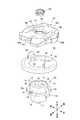
図1は、本発明に係るコマ玩具の一実施形態の遊び方を説明した図、図2は、本実施形態のコマ玩具の分解斜視図、図3は、本実施形態のコマ玩具の分解断面斜視図である。本明細書においては、上下、左右及び前後は図2及び図3に示した向きを言うものとする。
実施形態のコマ玩具1は、いわゆるバトルゲームに使用することが可能なコマ玩具である。具体的には、このコマ玩具1は、互いの衝突による衝撃力で相手方のコマ玩具1を図1の右側のように分解させて勝利とするようなバトルゲームに使用できる。
このコマ玩具1は、図2及び図3に示すように、下部構造を構成しドライバとなる軸部10と、上部構造を構成するレイヤーとなる性能可変リング30及び胴体40とによって構成されている。"overall structure"
FIG. 1 is a diagram illustrating how to play an embodiment of a top toy according to the present invention, FIG. 2 is an exploded perspective view of the top toy of this embodiment, and FIG. 3 is an exploded cross-sectional perspective view of the top toy of this embodiment. FIG. In the present specification, the top, bottom, left and right, and front and rear refer to the directions shown in FIGS.
The
As shown in FIGS. 2 and 3, the
《細部構成》
1.軸部10について
図2に示すように、軸部10は、下端部に回転軸11、上下方向中間部に鍔12、上部に円筒部13を備えている。
このうち鍔12と円筒部13とは一体に形成され軸部上部を構成し、この鍔12及び円筒部13は軸部下部に対してビス11c(図4参照)で固定されている。
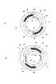
図4に示すように、軸部下部は、椀状の基体部品100と、この基体部品100の凹部101に内嵌される内嵌部品110とから構成されている。そして、基体部品100には、球状の回転軸11を抱持する円形の孔102が形成されるとともに、その半径方向外側には回転軸11の軸線を挟んで左右方向で対峙する部位2箇所のそれぞれに案内溝103が形成されている。2つの案内溝103は同一水平面の上に位置している。各案内溝103には球状の重錘部材25が1つずつ収容されている。なお、回転軸11は棒状であってもよい。なお、2つの案内溝103は、第1位置から第2位置に向けて多少下り傾斜(勾配)を持つように形成されていてもよい。また、2つの案内溝103は、第1位置から第2位置に向けて多少上り傾斜(勾配)を持つように形成されていてもよい。ただし、本発明の作用及び効果を妨げない範囲で傾斜させることが必要である。
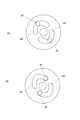
図7はこのコマ玩具1の模式的な平面図である。同図に示すように、各案内溝103は、上面視で回転軸11の軸心側に向けて凹となるように弓状に形成されている。各案内溝103をコマ玩具1における円周方向で見た場合、中心部の中心間距離が一番大きく(第1位置)、その中心部から案内溝103の両端に向けてその中心間距離が徐々に小さくなるように設定されている(2つの第2位置)。ここでの案内溝103は時計方向回転のコマ玩具1と反時計方向回転のコマ玩具1に対応できるように各案内溝103を上面視で弓形状に形成している。すなわち、ここでのコマ玩具1は、胴体40を変えることで回転方向を変更することができるが、軸部10は同じものを使用できるため、各案内溝103を上面視で弓形状に形成している。したがって、軸部10を時計方向回転のコマ玩具1や反時計方向回転のコマ玩具1のいずれか1つにだけ用いる場合には、1つの第1位置と1つの第2位置を持つように弧状の案内溝103とすれば足りる。
また、内嵌部品110は基体部品100の凹部101に嵌合するものである。この内嵌部品110は、内嵌状態で、前記案内溝103を塞いで当該案内溝103の天井を形成する。これにより重錘部材25の案内路が形成される。内嵌部品110には、図3に示すように、上方に突出する円筒部111と、下方に突出する円筒部112が形成されている。円筒部111は後述の円柱体16の空洞に嵌り込む。また、円筒部112は上記孔102に嵌り込んで回転軸11を下方に押圧する。<Detailed configuration>
1. About
Of these, the
As shown in FIG. 4, the lower portion of the shaft portion is composed of a bowl-
FIG. 7 is a schematic plan view of the
Further, the internal
鍔12及び円筒部13には、回転軸11の軸線を挟み前後方向で対峙する部位2箇所それぞれに孔14が形成されている。
また、円筒部13には、回転軸11の軸線を挟み左右方向で対峙する部位2箇所それぞれに突出部15が形成されている。この突出部15の外面は鍔12の外周面と面一となっている。
また、図3に示すように、円筒部13の内側には円柱体16が立設されている。この円柱体16は内部が空洞となり下方が開口している。また、図4に示すように、円柱体16の下端部には左右に突片16aが1つずつ形成され、そこにはビス挿通孔16bが形成されている。そして、円柱体16の空洞部には下側から内嵌部品110の円筒部111が嵌り込む、円柱体16の突片16aは内嵌部品110の凹部113に嵌まり込む。そして、基体部品100のビス挿通孔104と突片16aのビス挿通孔16bを通したビス11cによって円柱体16及び軸下部は軸部上部に取り付けられる。
円柱体16の上端は特に限定はされないが円筒部13の上端よりも高い位置に設定されている。この円柱体16の上端部には回転軸11の軸線を挟み前後方向で対峙する部位2箇所それぞれに半径方向外側に張り出す爪(係合部)17が形成されている。
Further, the
As shown in FIG. 3, a
The upper end of the
また、軸部10は円筒状の押圧部材18を備えている。この押圧部材18は、円筒部13の内側に円柱体16の外周を取り囲むようにして設置されている。
また、円筒部18aの外周下端部に脚部18cが設けられている。この脚部18cは回転軸11の軸線を挟み前後方向で対峙する部位2箇所それぞれに形成されている。そして。この押圧部材18はスプリング20によって上方に付勢されている。この押圧部材18は、脚部18cが孔14の上縁で上方への移動が規制され、常態では、押圧部材18の上端は円筒部13の上端と同一高さ位置にある。
また、押圧部材18の天井部の上面には、回転軸11の軸線を挟み左右方向で対峙する部位2箇所それぞれに半径方向に延びる凸条(突起)21が形成されている。The
A
Further, on the upper surface of the ceiling portion of the pressing
2.性能可変リング30について
この実施形態では、性能可変リング30としてフライホイールが用いられている。この性能可変リング30は板状を成している。図3に示すように、この性能可変リング30の底面には軸部10の鍔12が下方から収容可能な環状段部31が形成されている。また、図2及び図3に示すように、この性能可変リング30の上面には、回転軸11の軸線を挟み左右方向で対峙する部位2箇所それぞれに上方に向けて張り出す突出部32が形成されている。各突出部32の下側部分には、軸部10の突出部15を下方から収容可能な凹部33が形成されている。また、性能可変リング30の上面には、各突出部32の直ぐ外側に上方に延びる舌片34が形成されている。舌片34は突出部32よりも上方に突出している。なお、この性能可変リング30としては、フライホイールに代えて或いはフライホイールと一体的で、外周面に突出部があって相手方のコマ玩具1を攻撃し易くしたものや、外周面に凹部があって相手方のコマ玩具1からの攻撃を受け難いものであってもよい。2. About
3.胴体40について
胴体40は円盤状を成している。この胴体40は、図2に示すように、基体400と、上面視で基体400と略同形で基体400の上に被せられた透明カバー体401とを備えている。
胴体40の外周には凹凸40aが形成されている。また、基体400の中央には円孔41が形成されている。上記透明カバー体401は円孔41及び後述の弧状スリット46を除いた部分に被せられている。さらに、胴体40の下面には、性能可変リング30の突出部32を下方から収容可能な環状凹部42が形成されている。
この環状凹部42を区画形成する内周壁43aの内周面下端には、回転軸11の軸線を挟み前後方向で対峙する部位2箇所それぞれに半径方向内側に向けて張り出す爪(係合部)44が突設されている。
また、内周壁43aの内周面の上下方向中間部には、回転軸11の軸線を挟み左右方向で対峙する部位2箇所それぞれに半径方向内側に向けて張り出す突起47が突設されている。
さらに、内周壁43aの下端面には、回転軸11の軸線を挟み左右方向で対峙する部位2箇所それぞれに、凹凸が連続して形成され上記凸条21に噛み合う起伏部45が形成されている。
また、胴体40の環状凹部42を区画形成する天井壁43bには、性能可変リング30の舌片34を下方から挿入可能な弧状スリット46が形成されている。この弧状スリット46の長さは舌片34が十分に移動し得る長さとなっている。3. About the
Concavities and
At the lower end of the inner peripheral surface of the inner
In addition,
Further, on the lower end surface of the inner
An arc-shaped
4.識別用部品60について
識別用部品60は円孔41に取り付けられている。この識別用部品60はコマ玩具1の識別やプレイヤの識別のために使用される。
この識別のため、実施形態では、図示はしないが、この識別用部品60として互いに異なる模様及び/又は色を有するものが用意され、その中からプレイヤが選択した1つの識別用部品60が円孔41に突起47を利用してねじ式で取り付けられる。4). About the
For this identification, in the embodiment, although not shown in the drawings, the
《組立方法》 次に、コマ玩具1の組立方法の一例を説明する。なお、ここでは、軸部10の組立は既に終了しているものとする。また、識別用部品60の円孔41への取付けも終了しているものとする。
まず、軸部10の突出部15を下方から性能可変リング30の凹部33に合致させるようにして、軸部10と性能可変リング30を嵌合状態に組み付ける。次に、この組付け体を胴体40に下方から近付ける。この際、上記組付け体の性能可変リング30の舌片34を胴体40の弧状スリット46の所定の端に合致させる(図5(A))。この状態は、軸部10の爪17と胴体40の爪44とは上下方向で重なっていない状態である。この状態が係合解除状態である。その後、上記組付け体の軸部10を胴体40側に押圧する。すると、まず、性能可変リング30が胴体40の下面に押し当てられる。さらに、スプリング20が縮み、軸部10の爪17が胴体40の爪44よりも上方に相対的に押し上げられる。そして、軸部10を性能可変リング30と一体的に胴体40に対して舌片34が上記所定の端とは反対側の端まで移動するまで回転させる(図5(B))。この場合の回転は、胴体40及び性能可変リング30と軸部10との相対的な回転であって、図5(B)では、胴体40側を胴体40及び性能可変リング30に対して回転させた状態が示されている。すると、軸部10の爪17と胴体40の爪44とが上下で重なった状態となる。そして、軸部10から手を離すと、スプリング20の付勢力によって、軸部10の爪17の下面と胴体40の爪44の上面とが当接される。
軸部10の爪17の下面と胴体40の爪44の上面とが当接された状態が係合状態である。これにより、軸部10と、性能可変リング30及び胴体40が結合され、コマ玩具1が組み立てられる。<< Assembly Method >> Next, an example of an assembly method of the
First, the
A state where the lower surface of the
《遊び方》
続いて、このコマ玩具1を使用しての遊び方の一例を説明する。
この遊び方の一例では、コマ玩具1を回転させて、相手方のコマ玩具1と戦いを行う。
この場合、コマ玩具1の回転力のチャージは、図6に示すようなランチャー50によって行われる。このランチャー50は、内部に図示しない円板を備え、その円板を図示しないゼンマイばねで一の回転方向に付勢するとともに、円板の周囲に卷回させた図示しない紐をハンドル51で引くと、円板が回転され、コマホルダー53が回転されるように構成されている。このコマホルダー53の回転は、下方に突設されたフォーク54によってコマ玩具1に伝達され、コマ玩具1を回転する。この場合、フォーク54は胴体40の弧状スリット46に差し込まれる。そして、ランチャー50のハンドル51を引き切ると、円板ひいてはコマホルダー53の回転が停止する一方で、コマ玩具1は慣性力によって尚も回転するので、フォーク54の傾斜面54aを倣ってコマ玩具1がコマホルダー53から外れる。なお、図5において符号52はコマホルダー53に対して出没可能なロッドである。このロッド52はコマホルダー53にコマ玩具1を装着した際にコマ玩具1の上面に押されてコマホルダー53に没する。このロッド52は例えばコマ玩具1の着脱の検出に使用される。"how to play"
Next, an example of how to play using the
In an example of this way of playing, the
In this case, the rotational force of the
このようにして発射されたコマ玩具1は所定のフィールドで回転させられ、相手方のコマ玩具1に衝突すると、衝突による衝撃力や擦れ等によって、胴体40には、軸部10及び性能可変リング30の回転方向とは反対の方向の力が作用し、それによって、胴体40が軸部10及び性能可変リング30の回転方向に対して反対の方向に相対的に回転する。
すると、胴体40の起伏部45に凸条21が噛合する。この場合、凸条21にはスプリング20の付勢力が作用するので、衝突による衝撃力が作用する毎に、胴体40に対して軸部10が相対回転して噛み合い位置を変更することにより、係止解除位置に達すると、胴体40の爪44が軸部10の爪17から外れるため、スプリング20の付勢力によって胴体40が軸部10から離反する。そして、図1において、右側に示すように、コマ玩具1は分解される。The
Then, the
(案内溝103及び重錘部材25の作用及び効果)
重錘部材25は遠心力や慣性力によって案内溝103の第2位置側から第1位置が移動してその状態を保持する(図7(A))。そして、コマ玩具1が相手方のコマ玩具(図示せず)と衝突した際には、その衝撃によって重錘部材25が慣性力でコマ玩具1の回転方向に応じて案内溝103の第1位置側から1つの第2位置に移動する(図7(B))。すなわち、重錘部材25は、案内溝103においてコマ玩具1の回転軸心までの中心間距離がより小さい第2位置に移動する。重錘部材25が第2位置側へ移動すると、軸部10の回転エネルギや回転力が小さくなる。その結果、胴体40と軸部10とが外れる方向への相対回転を鈍らせ、分解までの時間を長くすることができる。したがって、本実施形態では、回転抵抗として、軸部10に凸条21を胴体40に凹条45を形成したが、所望の場合には、この回転抵抗を省略することもできる。(Operation and effect of the
The
《本発明の変形例》
以上、本発明の実施形態について説明したが、本発明は、かかる実施形態に限定されるものではなく、その要旨を逸脱しない範囲で、種々変形が可能であることは言うまでもない。<< Modification of the Present Invention >>
As mentioned above, although embodiment of this invention was described, it cannot be overemphasized that this invention is not limited to this embodiment, A various deformation | transformation is possible in the range which does not deviate from the summary.
例えば、上述した実施形態では、軸部10と胴体40との回転抵抗として、軸部10に凸条21を胴体40に起伏部45を形成したが、その他の形状の凸部と凹部とを形成してもよい。また、その数も上記実施形態に限定されない。さらに、回転抵抗は軸部10と胴体40との対向面に形成されたゴム等の抵抗であってもよい。この場合には、外部からの衝撃力等によって、軸部10と胴体40とが徐々に結合解除の方向に相対的に回転することになる。 For example, in the above-described embodiment, as the rotational resistance between the
また、上記実施形態では、案内溝103の半部を孤状にして全体として弓状に形成したが、案内溝103の半部を直線状にして全体としてV字状に形成してもよい。勿論、回転方向が特定されているコマ玩具に使用する場合には、V字状の案内溝103の半部だけを形成してもよい。 Moreover, in the said embodiment, although the half part of the
1 コマ玩具
10 軸部
23 溝部
24 段部
25 重錘部材
30 性能可変リング
34 舌片
40 胴体
46 弧状スリット
50 ランチャー
103 案内溝1
Claims (4)
Translated fromJapanese前記軸部には、回転軸の周りに、回転軸心までの中心間距離が最も大きい第1位置から当該中心間距離が前記第1位置よりも小さい第2位置までを繋ぐ案内溝が形成され、前記案内溝には当該案内溝の内部を移動可能に重錘部材が収容され、回転速度が増大する際には前記重錘部材が前記第2位置側から前記第1位置側に移動し、前記軸部と前記胴体が前記他方向に相対回転するような衝撃を受けた際には前記重錘部材が前記第1位置側から第2位置側へ移動することを特徴とするコマ玩具。The body has a body and a shaft, and by rotating the body relative to the shaft in one direction, the engaging portion of the shaft and the engaging portion of the body are engaged, and an impact received during rotation When the shaft and the body are subjected to a relative rotation force in the other direction, the engagement between the engagement portion of the shaft and the engagement portion of the body is released, and the shaft and the body are disengaged. In the top toy to be disassembled,
In the shaft portion, a guide groove is formed around the rotation axis to connect the first position having the largest center distance to the rotation axis to the second position having the center distance smaller than the first position. The weight member is accommodated in the guide groove so as to be movable in the guide groove, and when the rotation speed increases, the weight member moves from the second position side to the first position side, A top toy, wherein the weight member moves from the first position side to the second position side when receiving an impact such that the shaft portion and the body rotate relative to each other in the other direction.
Priority Applications (4)
| Application Number | Priority Date | Filing Date | Title |
|---|---|---|---|
| JP2017035083AJP6232153B1 (en) | 2017-02-27 | 2017-02-27 | Top toy |
| CN201721143835.8UCN207384826U (en) | 2017-02-27 | 2017-09-07 | Toy top |
| US15/899,645US20180243661A1 (en) | 2017-02-27 | 2018-02-20 | Spinning top toy |
| EP18158877.3AEP3366360A1 (en) | 2017-02-27 | 2018-02-27 | Spinning top toy |
Applications Claiming Priority (1)
| Application Number | Priority Date | Filing Date | Title |
|---|---|---|---|
| JP2017035083AJP6232153B1 (en) | 2017-02-27 | 2017-02-27 | Top toy |
Publications (2)
| Publication Number | Publication Date |
|---|---|
| JP6232153B1 JP6232153B1 (en) | 2017-11-15 |
| JP2018139744Atrue JP2018139744A (en) | 2018-09-13 |
Family
ID=60321162
Family Applications (1)
| Application Number | Title | Priority Date | Filing Date |
|---|---|---|---|
| JP2017035083AActiveJP6232153B1 (en) | 2017-02-27 | 2017-02-27 | Top toy |
Country Status (4)
| Country | Link |
|---|---|
| US (1) | US20180243661A1 (en) |
| EP (1) | EP3366360A1 (en) |
| JP (1) | JP6232153B1 (en) |
| CN (1) | CN207384826U (en) |
Cited By (2)
| Publication number | Priority date | Publication date | Assignee | Title |
|---|---|---|---|---|
| CN109966750A (en)* | 2019-03-29 | 2019-07-05 | 浙江传媒学院 | A voice-activated splicing toy |
| KR20210063197A (en)* | 2019-11-22 | 2021-06-01 | 가부시키가이샤 다까라토미 | Toy top |
Families Citing this family (2)
| Publication number | Priority date | Publication date | Assignee | Title |
|---|---|---|---|---|
| USD883399S1 (en)* | 2019-07-30 | 2020-05-05 | Shaofu He | Pneumatic spinning top |
| JP7487894B2 (en)* | 2022-10-06 | 2024-05-21 | 株式会社タカラトミー | Top toy |
Family Cites Families (23)
| Publication number | Priority date | Publication date | Assignee | Title |
|---|---|---|---|---|
| US547764A (en)* | 1895-10-15 | Spinning-top | ||
| US1780547A (en)* | 1928-10-11 | 1930-11-04 | Alland Maurice | Top |
| US2139507A (en)* | 1937-09-04 | 1938-12-06 | Laing Nathan | Spinning top |
| US2332507A (en)* | 1940-11-04 | 1943-10-26 | Owen R Dailey | Top |
| US2631405A (en)* | 1948-02-02 | 1953-03-17 | Neilson K Masten | Toy top |
| US2818676A (en)* | 1952-10-20 | 1958-01-07 | Jonker Frederick | Spinning tops |
| US3246427A (en)* | 1965-02-18 | 1966-04-19 | Armas A Tuuri | Electric top with power source and centrifugal switch |
| US3638350A (en)* | 1970-09-02 | 1972-02-01 | Fantastic Futures Inc | Toy |
| US4015365A (en)* | 1975-08-29 | 1977-04-05 | Kohner, Inc. | Child's toy |
| US4538999A (en)* | 1981-04-01 | 1985-09-03 | Fun-Tech Products Company | Spinning toy |
| US5951353A (en)* | 1998-04-03 | 1999-09-14 | Moore; David Denny | Disk for throwing and rolling |
| JP3071767U (en)* | 2000-03-15 | 2000-09-22 | 株式会社タカラ | Top toy |
| US6364734B1 (en)* | 2000-04-14 | 2002-04-02 | Ricky Ng | Toy top structure and system |
| JP3612508B2 (en)* | 2001-09-28 | 2005-01-19 | 株式会社タカラ | Top toy system |
| JP3088350U (en)* | 2002-03-05 | 2002-09-06 | 株式会社タカラ | Top toy |
| JP2004201979A (en)* | 2002-12-25 | 2004-07-22 | Takara Co Ltd | Top toy |
| US6969296B1 (en)* | 2005-01-24 | 2005-11-29 | Yi Ta Chen | Top with a lighting device |
| US20070021029A1 (en)* | 2005-06-06 | 2007-01-25 | Erich Weidetz | Games with adjustable spinning tops |
| KR101051847B1 (en)* | 2009-06-22 | 2011-07-25 | 최신규 | Toy top |
| JP5756581B1 (en)* | 2015-03-31 | 2015-07-29 | 株式会社タカラトミー | Information logger device |
| JP5959773B1 (en)* | 2016-01-19 | 2016-08-02 | 株式会社タカラトミー | Top toy |
| JP6184576B1 (en)* | 2016-10-18 | 2017-08-23 | 株式会社タカラトミー | Top toy |
| JP6236177B1 (en)* | 2017-02-27 | 2017-11-22 | 株式会社タカラトミー | Top toy |
- 2017
- 2017-02-27JPJP2017035083Apatent/JP6232153B1/enactiveActive
- 2017-09-07CNCN201721143835.8Upatent/CN207384826U/ennot_activeExpired - Fee Related
- 2018
- 2018-02-20USUS15/899,645patent/US20180243661A1/ennot_activeAbandoned
- 2018-02-27EPEP18158877.3Apatent/EP3366360A1/ennot_activeWithdrawn
Cited By (4)
| Publication number | Priority date | Publication date | Assignee | Title |
|---|---|---|---|---|
| CN109966750A (en)* | 2019-03-29 | 2019-07-05 | 浙江传媒学院 | A voice-activated splicing toy |
| CN109966750B (en)* | 2019-03-29 | 2020-12-22 | 浙江传媒学院 | A voice-activated splicing toy |
| KR20210063197A (en)* | 2019-11-22 | 2021-06-01 | 가부시키가이샤 다까라토미 | Toy top |
| KR102429691B1 (en)* | 2019-11-22 | 2022-08-05 | 가부시키가이샤 다까라토미 | Toy top |
Also Published As
| Publication number | Publication date |
|---|---|
| JP6232153B1 (en) | 2017-11-15 |
| US20180243661A1 (en) | 2018-08-30 |
| EP3366360A1 (en) | 2018-08-29 |
| CN207384826U (en) | 2018-05-22 |
Similar Documents
| Publication | Publication Date | Title |
|---|---|---|
| JP5793631B1 (en) | Top toy | |
| KR102332707B1 (en) | Spinning top toy | |
| JP6431629B1 (en) | Top toy | |
| JP5990354B1 (en) | Top toy | |
| JP6250202B1 (en) | Top toy | |
| JP5969151B1 (en) | Top toy | |
| JP6111365B1 (en) | Top toy | |
| JP6377211B1 (en) | Top toy | |
| JP2017127427A (en) | Top toy | |
| JP6570019B1 (en) | Top toy | |
| JP6232153B1 (en) | Top toy | |
| JP6232113B1 (en) | Top toy and method for attaching top toy parts | |
| JP6377217B1 (en) | Top toy | |
| JP6236177B1 (en) | Top toy | |
| JP2018126424A (en) | Toy top | |
| JP6904543B2 (en) | Top toys | |
| JP6516587B2 (en) | Top toy | |
| JP6346976B1 (en) | Top toy | |
| JP6644338B1 (en) | Top toy | |
| JP5959711B1 (en) | Top toy | |
| JP6250203B1 (en) | Top toy | |
| JP2019216990A (en) | Toy top |
Legal Events
| Date | Code | Title | Description |
|---|---|---|---|
| A621 | Written request for application examination | Free format text:JAPANESE INTERMEDIATE CODE: A621 Effective date:20170915 | |
| A871 | Explanation of circumstances concerning accelerated examination | Free format text:JAPANESE INTERMEDIATE CODE: A871 Effective date:20170915 | |
| TRDD | Decision of grant or rejection written | ||
| A975 | Report on accelerated examination | Free format text:JAPANESE INTERMEDIATE CODE: A971005 Effective date:20171003 | |
| A01 | Written decision to grant a patent or to grant a registration (utility model) | Free format text:JAPANESE INTERMEDIATE CODE: A01 Effective date:20171010 | |
| A61 | First payment of annual fees (during grant procedure) | Free format text:JAPANESE INTERMEDIATE CODE: A61 Effective date:20171020 | |
| R150 | Certificate of patent or registration of utility model | Ref document number:6232153 Country of ref document:JP Free format text:JAPANESE INTERMEDIATE CODE: R150 | |
| R250 | Receipt of annual fees | Free format text:JAPANESE INTERMEDIATE CODE: R250 | |
| R250 | Receipt of annual fees | Free format text:JAPANESE INTERMEDIATE CODE: R250 | |
| R250 | Receipt of annual fees | Free format text:JAPANESE INTERMEDIATE CODE: R250 | |
| R250 | Receipt of annual fees | Free format text:JAPANESE INTERMEDIATE CODE: R250 | |
| R250 | Receipt of annual fees | Free format text:JAPANESE INTERMEDIATE CODE: R250 | |
| R250 | Receipt of annual fees | Free format text:JAPANESE INTERMEDIATE CODE: R250 |