JP2018133871A - Vehicle controller - Google Patents
Vehicle controllerDownload PDFInfo
- Publication number
- JP2018133871A JP2018133871AJP2017024734AJP2017024734AJP2018133871AJP 2018133871 AJP2018133871 AJP 2018133871AJP 2017024734 AJP2017024734 AJP 2017024734AJP 2017024734 AJP2017024734 AJP 2017024734AJP 2018133871 AJP2018133871 AJP 2018133871A
- Authority
- JP
- Japan
- Prior art keywords
- battery
- alternator
- switch
- generator
- vehicle
- Prior art date
- Legal status (The legal status is an assumption and is not a legal conclusion. Google has not performed a legal analysis and makes no representation as to the accuracy of the status listed.)
- Granted
Links
Images


Classifications
- B—PERFORMING OPERATIONS; TRANSPORTING
- B60—VEHICLES IN GENERAL
- B60L—PROPULSION OF ELECTRICALLY-PROPELLED VEHICLES; SUPPLYING ELECTRIC POWER FOR AUXILIARY EQUIPMENT OF ELECTRICALLY-PROPELLED VEHICLES; ELECTRODYNAMIC BRAKE SYSTEMS FOR VEHICLES IN GENERAL; MAGNETIC SUSPENSION OR LEVITATION FOR VEHICLES; MONITORING OPERATING VARIABLES OF ELECTRICALLY-PROPELLED VEHICLES; ELECTRIC SAFETY DEVICES FOR ELECTRICALLY-PROPELLED VEHICLES
- B60L15/00—Methods, circuits, or devices for controlling the traction-motor speed of electrically-propelled vehicles
- B60L15/20—Methods, circuits, or devices for controlling the traction-motor speed of electrically-propelled vehicles for control of the vehicle or its driving motor to achieve a desired performance, e.g. speed, torque, programmed variation of speed
- B60L15/2009—Methods, circuits, or devices for controlling the traction-motor speed of electrically-propelled vehicles for control of the vehicle or its driving motor to achieve a desired performance, e.g. speed, torque, programmed variation of speed for braking
- B—PERFORMING OPERATIONS; TRANSPORTING
- B60—VEHICLES IN GENERAL
- B60L—PROPULSION OF ELECTRICALLY-PROPELLED VEHICLES; SUPPLYING ELECTRIC POWER FOR AUXILIARY EQUIPMENT OF ELECTRICALLY-PROPELLED VEHICLES; ELECTRODYNAMIC BRAKE SYSTEMS FOR VEHICLES IN GENERAL; MAGNETIC SUSPENSION OR LEVITATION FOR VEHICLES; MONITORING OPERATING VARIABLES OF ELECTRICALLY-PROPELLED VEHICLES; ELECTRIC SAFETY DEVICES FOR ELECTRICALLY-PROPELLED VEHICLES
- B60L53/00—Methods of charging batteries, specially adapted for electric vehicles; Charging stations or on-board charging equipment therefor; Exchange of energy storage elements in electric vehicles
- H—ELECTRICITY
- H02—GENERATION; CONVERSION OR DISTRIBUTION OF ELECTRIC POWER
- H02J—CIRCUIT ARRANGEMENTS OR SYSTEMS FOR SUPPLYING OR DISTRIBUTING ELECTRIC POWER; SYSTEMS FOR STORING ELECTRIC ENERGY
- H02J7/00—Circuit arrangements for charging or depolarising batteries or for supplying loads from batteries
- H02J7/14—Circuit arrangements for charging or depolarising batteries or for supplying loads from batteries for charging batteries from dynamo-electric generators driven at varying speed, e.g. on vehicle
- H02J7/1423—Circuit arrangements for charging or depolarising batteries or for supplying loads from batteries for charging batteries from dynamo-electric generators driven at varying speed, e.g. on vehicle with multiple batteries
- B—PERFORMING OPERATIONS; TRANSPORTING
- B60—VEHICLES IN GENERAL
- B60L—PROPULSION OF ELECTRICALLY-PROPELLED VEHICLES; SUPPLYING ELECTRIC POWER FOR AUXILIARY EQUIPMENT OF ELECTRICALLY-PROPELLED VEHICLES; ELECTRODYNAMIC BRAKE SYSTEMS FOR VEHICLES IN GENERAL; MAGNETIC SUSPENSION OR LEVITATION FOR VEHICLES; MONITORING OPERATING VARIABLES OF ELECTRICALLY-PROPELLED VEHICLES; ELECTRIC SAFETY DEVICES FOR ELECTRICALLY-PROPELLED VEHICLES
- B60L2240/00—Control parameters of input or output; Target parameters
- B60L2240/10—Vehicle control parameters
- B60L2240/36—Temperature of vehicle components or parts
- B—PERFORMING OPERATIONS; TRANSPORTING
- B60—VEHICLES IN GENERAL
- B60L—PROPULSION OF ELECTRICALLY-PROPELLED VEHICLES; SUPPLYING ELECTRIC POWER FOR AUXILIARY EQUIPMENT OF ELECTRICALLY-PROPELLED VEHICLES; ELECTRODYNAMIC BRAKE SYSTEMS FOR VEHICLES IN GENERAL; MAGNETIC SUSPENSION OR LEVITATION FOR VEHICLES; MONITORING OPERATING VARIABLES OF ELECTRICALLY-PROPELLED VEHICLES; ELECTRIC SAFETY DEVICES FOR ELECTRICALLY-PROPELLED VEHICLES
- B60L2240/00—Control parameters of input or output; Target parameters
- B60L2240/40—Drive Train control parameters
- B60L2240/42—Drive Train control parameters related to electric machines
- B60L2240/423—Torque
- B—PERFORMING OPERATIONS; TRANSPORTING
- B60—VEHICLES IN GENERAL
- B60L—PROPULSION OF ELECTRICALLY-PROPELLED VEHICLES; SUPPLYING ELECTRIC POWER FOR AUXILIARY EQUIPMENT OF ELECTRICALLY-PROPELLED VEHICLES; ELECTRODYNAMIC BRAKE SYSTEMS FOR VEHICLES IN GENERAL; MAGNETIC SUSPENSION OR LEVITATION FOR VEHICLES; MONITORING OPERATING VARIABLES OF ELECTRICALLY-PROPELLED VEHICLES; ELECTRIC SAFETY DEVICES FOR ELECTRICALLY-PROPELLED VEHICLES
- B60L2240/00—Control parameters of input or output; Target parameters
- B60L2240/40—Drive Train control parameters
- B60L2240/52—Drive Train control parameters related to converters
- B60L2240/525—Temperature of converter or components thereof
- Y—GENERAL TAGGING OF NEW TECHNOLOGICAL DEVELOPMENTS; GENERAL TAGGING OF CROSS-SECTIONAL TECHNOLOGIES SPANNING OVER SEVERAL SECTIONS OF THE IPC; TECHNICAL SUBJECTS COVERED BY FORMER USPC CROSS-REFERENCE ART COLLECTIONS [XRACs] AND DIGESTS
- Y02—TECHNOLOGIES OR APPLICATIONS FOR MITIGATION OR ADAPTATION AGAINST CLIMATE CHANGE
- Y02T—CLIMATE CHANGE MITIGATION TECHNOLOGIES RELATED TO TRANSPORTATION
- Y02T10/00—Road transport of goods or passengers
- Y02T10/60—Other road transportation technologies with climate change mitigation effect
- Y02T10/64—Electric machine technologies in electromobility
- Y—GENERAL TAGGING OF NEW TECHNOLOGICAL DEVELOPMENTS; GENERAL TAGGING OF CROSS-SECTIONAL TECHNOLOGIES SPANNING OVER SEVERAL SECTIONS OF THE IPC; TECHNICAL SUBJECTS COVERED BY FORMER USPC CROSS-REFERENCE ART COLLECTIONS [XRACs] AND DIGESTS
- Y02—TECHNOLOGIES OR APPLICATIONS FOR MITIGATION OR ADAPTATION AGAINST CLIMATE CHANGE
- Y02T—CLIMATE CHANGE MITIGATION TECHNOLOGIES RELATED TO TRANSPORTATION
- Y02T10/00—Road transport of goods or passengers
- Y02T10/60—Other road transportation technologies with climate change mitigation effect
- Y02T10/70—Energy storage systems for electromobility, e.g. batteries
- Y—GENERAL TAGGING OF NEW TECHNOLOGICAL DEVELOPMENTS; GENERAL TAGGING OF CROSS-SECTIONAL TECHNOLOGIES SPANNING OVER SEVERAL SECTIONS OF THE IPC; TECHNICAL SUBJECTS COVERED BY FORMER USPC CROSS-REFERENCE ART COLLECTIONS [XRACs] AND DIGESTS
- Y02—TECHNOLOGIES OR APPLICATIONS FOR MITIGATION OR ADAPTATION AGAINST CLIMATE CHANGE
- Y02T—CLIMATE CHANGE MITIGATION TECHNOLOGIES RELATED TO TRANSPORTATION
- Y02T10/00—Road transport of goods or passengers
- Y02T10/60—Other road transportation technologies with climate change mitigation effect
- Y02T10/7072—Electromobility specific charging systems or methods for batteries, ultracapacitors, supercapacitors or double-layer capacitors
- Y—GENERAL TAGGING OF NEW TECHNOLOGICAL DEVELOPMENTS; GENERAL TAGGING OF CROSS-SECTIONAL TECHNOLOGIES SPANNING OVER SEVERAL SECTIONS OF THE IPC; TECHNICAL SUBJECTS COVERED BY FORMER USPC CROSS-REFERENCE ART COLLECTIONS [XRACs] AND DIGESTS
- Y02—TECHNOLOGIES OR APPLICATIONS FOR MITIGATION OR ADAPTATION AGAINST CLIMATE CHANGE
- Y02T—CLIMATE CHANGE MITIGATION TECHNOLOGIES RELATED TO TRANSPORTATION
- Y02T10/00—Road transport of goods or passengers
- Y02T10/60—Other road transportation technologies with climate change mitigation effect
- Y02T10/72—Electric energy management in electromobility
- Y—GENERAL TAGGING OF NEW TECHNOLOGICAL DEVELOPMENTS; GENERAL TAGGING OF CROSS-SECTIONAL TECHNOLOGIES SPANNING OVER SEVERAL SECTIONS OF THE IPC; TECHNICAL SUBJECTS COVERED BY FORMER USPC CROSS-REFERENCE ART COLLECTIONS [XRACs] AND DIGESTS
- Y02—TECHNOLOGIES OR APPLICATIONS FOR MITIGATION OR ADAPTATION AGAINST CLIMATE CHANGE
- Y02T—CLIMATE CHANGE MITIGATION TECHNOLOGIES RELATED TO TRANSPORTATION
- Y02T90/00—Enabling technologies or technologies with a potential or indirect contribution to GHG emissions mitigation
- Y02T90/10—Technologies relating to charging of electric vehicles
- Y02T90/14—Plug-in electric vehicles
Landscapes
- Engineering & Computer Science (AREA)
- Power Engineering (AREA)
- Transportation (AREA)
- Mechanical Engineering (AREA)
- Charge And Discharge Circuits For Batteries Or The Like (AREA)
- Electric Propulsion And Braking For Vehicles (AREA)
- Control Of Charge By Means Of Generators (AREA)
- Control Of Eletrric Generators (AREA)
Abstract
Translated fromJapaneseDescription
Translated fromJapanese本発明は、車両の制御装置に関する。 The present invention relates to a vehicle control device.
従来、エンジンの回転によって発電可能な発電機と、その発電機により充電可能な第1バッテリおよび第2バッテリとを備える車両が知られている(たとえば、特許文献1参照)。このような車両では、充電性能が向上されることから、発電機の発電電力量が増えるため、発電機の負荷が高くなりやすい。 2. Description of the Related Art Conventionally, a vehicle is known that includes a generator that can generate electricity by rotating an engine, and a first battery and a second battery that can be charged by the generator (see, for example, Patent Document 1). In such a vehicle, since the charging performance is improved, the amount of electric power generated by the generator increases, so the load on the generator tends to increase.
そして、上記のような車両において、発電機の負荷が高くなった場合に、発電機の保護のために、発電機の発電電圧を低下させると、電圧変動により補機の動作が影響を受けるおそれがある。 In the vehicle as described above, when the generator load becomes high, if the generator voltage is reduced to protect the generator, the operation of the accessory may be affected by voltage fluctuation. There is.
本発明は、上記の課題を解決するためになされたものであり、本発明の目的は、発電機の保護を図りながら、電圧変動の発生を抑制することが可能な車両の制御装置を提供することである。 The present invention has been made to solve the above problems, and an object of the present invention is to provide a vehicle control device capable of suppressing the occurrence of voltage fluctuations while protecting the generator. That is.
本発明による車両の制御装置は、エンジンの回転によって発電可能な発電機と、発電機により充電可能な第1バッテリおよび第2バッテリとを備え、第1バッテリが発電機と並列に接続されるとともに、第2バッテリが開閉器を介して発電機および第1バッテリと並列に接続されている車両に適用されるものである。車両の制御装置は、発電機の負荷が高くなることが予測される場合に、開閉器を開くことにより、発電機で発電される回生電力が第2バッテリに充電されないように構成されている。なお、発電機の負荷とは、たとえば、発電機の耐久性に影響を与える熱的な負荷である。 A vehicle control apparatus according to the present invention includes a generator that can generate electricity by rotating an engine, a first battery and a second battery that can be charged by the generator, and the first battery is connected in parallel to the generator. The second battery is applied to a vehicle connected in parallel with the generator and the first battery via a switch. The vehicle control device is configured so that regenerative power generated by the generator is not charged in the second battery by opening the switch when the load on the generator is predicted to increase. The generator load is, for example, a thermal load that affects the durability of the generator.
このように構成することによって、第2バッテリが充電されないことにより、その分、発電機での発電電力量を低下させることができる。これにより、発電機の発電電圧を低下させることなく、発電機の負荷の低減を図ることができる。 By comprising in this way, when the 2nd battery is not charged, the electric power generation amount in a generator can be reduced by that much. Thereby, reduction of the load of a generator can be aimed at, without reducing the generated voltage of a generator.
上記車両の制御装置において、発電機の負荷が高くなることが予測される場合に、発電機の発電トルクが所定閾値を超えているときに、開閉器を閉じたままにするように構成されていてもよい。 The vehicle control device is configured to keep the switch closed when the generator load is predicted to increase when the generator torque exceeds a predetermined threshold. May be.
このように構成すれば、回生発電中に制動トルクの抜けが発生するのを抑制することができるので、ドライバビリティの低下を抑制することができる。 If comprised in this way, since it can suppress that the loss of braking torque generate | occur | produces during regenerative power generation, the fall of drivability can be suppressed.
この場合において、発電機の負荷が高くなることが予測される場合に、発電機の発電トルクが所定閾値を下回ったときに、開閉器を開くように構成されていてもよい。 In this case, when the load on the generator is predicted to increase, the switch may be configured to open when the power generation torque of the generator falls below a predetermined threshold.
このように構成すれば、ドライバビリティの低下を抑制しながら、回生電力が第2バッテリに充電されないようにすることができる。 If comprised in this way, regenerative electric power can be prevented from being charged to a 2nd battery, suppressing the fall of drivability.
上記車両の制御装置において、第2バッテリは、第1バッテリに比べて、高出力および/または高容量であってもよい。 In the vehicle control apparatus, the second battery may have a higher output and / or a higher capacity than the first battery.
このように構成すれば、第2バッテリを切り離すことにより、発電機の負荷を大きく減らすことができる。 If comprised in this way, the load of a generator can be reduced significantly by isolate | separating a 2nd battery.
上記車両の制御装置において、発電機の負荷が高くなることが予測される場合は、発電機の温度が所定値よりも大きい場合を含んでいてもよい。 In the vehicle control apparatus, when the load on the generator is predicted to increase, the case where the temperature of the generator is higher than a predetermined value may be included.
このように構成すれば、発電機の温度が所定値よりも大きい場合に、開閉器を開くことにより、回生電力が第2バッテリに充電されないようにすることができる。 If comprised in this way, when the temperature of a generator is larger than predetermined value, it can prevent regenerative electric power from being charged by the 2nd battery by opening a switch.
本発明の車両の制御装置によれば、発電機の保護を図りながら、電圧変動の発生を抑制することができる。 According to the vehicle control apparatus of the present invention, it is possible to suppress the occurrence of voltage fluctuations while protecting the generator.
以下、本発明の一実施形態を図面に基づいて説明する。 Hereinafter, an embodiment of the present invention will be described with reference to the drawings.
まず、図1および図2を参照して、本発明の一実施形態によるECU6を備える車両100について説明する。 First, a
車両100は、図1に示すように、オルタネータ1と、第1補機2と、第1バッテリ3と、第2補機4と、第2バッテリ5と、ECU6とを備えている。この車両100は、図示省略したエンジン(内燃機関)から走行用の駆動力が出力されるように構成されている。 As shown in FIG. 1, the
オルタネータ1は、エンジンの回転によって発電可能に構成されている。このオルタネータ1では、発電電圧を調整することにより、発電電力量を調整することが可能である。オルタネータ1により発電された電力は、第1バッテリ3および第2バッテリ5の充電や、第1補機2および第2補機4の駆動に用いられる。なお、オルタネータ1は、本発明の「発電機」の一例である。 The
たとえば、オルタネータ1は、電磁誘導により交流電流を発生させる交流発電機と、交流電流を直流電流に変換する整流器と、直流電流の電圧を調整するレギュレータとを含んでいる。交流発電機は、発電コイルが設けられたステータと、励磁コイルが設けられたロータとを有し、ロータがエンジンの出力軸に連結されている。そして、交流発電機では、ロータが回転するときの励磁コイルの電流(励磁電流)に応じて発電コイルに交流電流が発生するようになっている。レギュレータは、励磁コイルに供給する電流を調整することにより、オルタネータ1の発電電圧を調整するように構成されている。 For example, the
第1補機2は、車両に搭載された負荷機器であり、バックアップ電源が必要とされない補機である。この第1補機2は、オルタネータ1、第1バッテリ3および第2バッテリ5から供給される電力により作動するように構成されている。第1補機2の一例としては、ライトを挙げることができる。 The first
第1バッテリ3は、オルタネータ1で発電された電力を蓄電するとともに、蓄電した電力を第1補機2および第2補機4に供給するように構成されている。この第1バッテリ3は、たとえば、定格電圧が12Vの鉛蓄電池である。このため、第1バッテリ3は、図2に示すように、たとえばSOC(State of Charge:充電状態)が90〜100%となるように運用される。 The
第2補機4は、図1に示すように、車両に搭載された負荷機器であり、バックアップ電源が必要とされる補機である。すなわち、第2補機4は、第1補機2に比べて高い信頼性が要求される補機である。この第2補機4は、オルタネータ1、第1バッテリ3および第2バッテリ5から供給される電力により作動するように構成されている。第2補機4の一例としては、シフトバイワイヤを挙げることができる。 As shown in FIG. 1, the second auxiliary machine 4 is a load device mounted on the vehicle, and is an auxiliary machine that requires a backup power source. In other words, the second auxiliary machine 4 is an auxiliary machine that requires higher reliability than the first
第2バッテリ5は、オルタネータ1で発電された電力を蓄電するとともに、蓄電した電力を第1補機2および第2補機4に供給するように構成されている。この第2バッテリ5は、たとえば、定格電圧が12Vのニッケル水素二次電池である。このため、第2バッテリ5は、図2に示すように、たとえばSOCが30〜70%となるように運用される。また、第2バッテリ5は、第1バッテリ3に比べて、高出力および高容量である。すなわち、第2バッテリ5は、第1バッテリ3に比べて、出力密度およびエネルギー密度が高い。なお、第2バッテリ5は、後述するように、第2補機4のバックアップ電源として機能するように構成されている。 The
ECU6は、図1に示すように、車両100を制御するように構成されている。たとえば、ECU6は、第1バッテリ3および第2バッテリ5のSOCが適切な値になるように、オルタネータ1の発電電圧を制御する。このECU6は、オルタネータ1、第1バッテリ3および第2バッテリ5から供給される電力により作動するように構成されている。なお、ECU6は、本発明の「車両の制御装置」の一例である。 The ECU 6 is configured to control the
このECU6は、CPU、ROM、RAM、バックアップRAMおよび入出力インターフェースなどを含んでいる。たとえば、ECU6には、オルタネータ1の温度を検出する温度センサ11、第1バッテリ3の充放電電流を検出する電流センサ、第1バッテリ3の電圧を検出する電圧センサ、第1バッテリ3の温度を検出する温度センサ、第2バッテリ5の充放電電流を検出する電流センサ、第2バッテリ5の電圧を検出する電圧センサ、および、第2バッテリ5の温度を検出する温度センサなどが接続されている。なお、SOCは、たとえば充放電電流の積算値に基づいて算出される。 The ECU 6 includes a CPU, a ROM, a RAM, a backup RAM, an input / output interface, and the like. For example, the ECU 6 includes a
ここで、オルタネータ1、第1補機2および第1バッテリ3は、それぞれ、一端が電源ラインPL1に接続され、他端が接地されている。このため、オルタネータ1、第1補機2および第1バッテリ3が並列に接続されている。 Here, each of the
第2補機4は、一端が電源ラインPL2に接続され、他端が接地されている。電源ラインPL2は第1スイッチ7を介して電源ラインPL1に接続されている。すなわち、第2補機4は、第1スイッチ7を介して、オルタネータ1、第1補機2および第1バッテリ3と並列に接続されている。 The second auxiliary machine 4 has one end connected to the power supply line PL2 and the other end grounded. The power line PL2 is connected to the power line PL1 through the
第2バッテリ5は、一端が第2スイッチ8を介して電源ラインPL2に接続され、他端が接地されている。すなわち、第2バッテリ5は、第2スイッチ8を介して第2補機4と並列に接続されている。また、第2バッテリ5は、第1スイッチ7および第2スイッチ8を介して、オルタネータ1、第1補機2および第1バッテリ3と並列に接続されている。 The
第1スイッチ7および第2スイッチ8は、たとえば電磁リレーであり、ECU6により開閉が制御されるように構成されている。なお、第2スイッチ8は、本発明の「開閉器」の一例である。 The
ECU6は、通常時に、第1スイッチ7および第2スイッチ8を閉じる(オン状態にする)ように構成されている。これにより、第1補機2および第2補機4には、オルタネータ1、第1バッテリ3および第2バッテリ5のいずれかから電力が供給される。なお、オルタネータ1の発電電圧が第1バッテリ3および第2バッテリ5のOCV(Open Circuit Voltage:開路電圧)よりも高い場合には、オルタネータ1の発電電力により第1バッテリ3および第2バッテリ5が充電される。 The ECU 6 is configured to close (turn on) the
そして、ECU6は、第1バッテリ3の故障時や電源ラインPL1の地絡時に、第2スイッチ8を閉じたまま、第1スイッチ7を開く(オフ状態にする)ように構成されている。このとき、第2補機4には第2バッテリ5から電力が供給され、第2補機4が作動可能である。また、ECU6は、第2バッテリ5の劣化時に、第1スイッチ7を閉じたまま、第2スイッチ8を開くように構成されている。これにより、第2バッテリ5を電源ラインPL2から切り離すことが可能である。なお、以下では、これらの不具合が発生していない場合、すなわち通常時である場合について説明するが、後述するように、通常時であっても第2スイッチ8を開く場合がある。また、以下では、第1スイッチ7および第2スイッチ8の開閉状態をオンオフ状態で言い換える。 The ECU 6 is configured to open the first switch 7 (turn it off) while the
このような車両100では、定速時や加速時には、第1補機2および第2補機4に対して主に第1バッテリ3および第2バッテリ5から電力を供給し、オルタネータ1での発電を抑制して燃費の改善を図りながら、減速制動時には、オルタネータ1で発電された回生電力により第1バッテリ3および第2バッテリ5を充電するようになっている。すなわち、エンジン駆動時の発電負荷を低減して燃費の改善を図りながら、エンジン被駆動時に回生発電によって第1バッテリ3および第2バッテリ5を充電している。 In such a
具体的には、ECU6は、減速制動時に、オルタネータ1の温度が第1所定値Th1以下の場合に、第1スイッチ7および第2スイッチ8をオン状態にし、第1バッテリ3および第2バッテリ5の両方で回生制御を行うように構成されている。第1所定値Th1は、予め設定された値であり、オルタネータ1が過熱状態になる手前の高い温度値(たとえば、120℃)である。なお、第1所定値Th1は、本発明の「所定値」の一例である。 Specifically, the ECU 6 turns on the
そして、本実施形態では、ECU6は、減速制動時に、オルタネータ1の温度が第1所定値Th1よりも大きい場合に、第2スイッチ8をオフ状態にし、第1バッテリ3のみで回生制御を行うように構成されている。これにより、第2バッテリ5が切り離されることから、オルタネータ1での発電電力量が低下され、オルタネータ1の温度上昇を抑制することが可能である。なお、オルタネータ1の温度が第1所定値Th1よりも大きい場合は、本発明の「発電機の負荷が高くなることが予測される場合」の一例である。 In the present embodiment, during deceleration braking, the ECU 6 turns off the
なお、ECU6は、減速制動時に、オルタネータ1の温度が第2所定値Th2よりも大きい場合に、回生制御を禁止するように構成されている。第2所定値Th2は、予め設定された第1所定値Th1よりも大きい値であり、オルタネータ1が過熱状態になる高い温度値(たとえば、180℃)である。 The ECU 6 is configured to prohibit the regenerative control when the temperature of the
−減速制動時におけるECUによる制御−
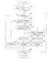
次に、図3を参照して、車両100の減速制動時におけるECU6による制御の一例について説明する。なお、以下のフローでは、減速制動時についてのみ説明し、定速時や加速時についての説明を省略する。また、以下の各ステップはECU6により実行される。-Control by ECU during deceleration braking-
Next, an example of control by the ECU 6 during deceleration braking of the
まず、図3のステップS1において、イグニッションスイッチ(図示省略)のオン操作がされたか否かが判断される。そして、イグニッションスイッチのオン操作がされたと判断された場合には、ステップS2に移る。なお、ステップS2に移るときには、第1スイッチ7および第2スイッチ8がオン状態である。その一方、イグニッションスイッチのオン操作がされていないと判断された場合には、ステップS1が繰り返し行われる。すなわち、イグニッションスイッチがオン操作されるまで待機する。 First, in step S1 of FIG. 3, it is determined whether or not an ignition switch (not shown) is turned on. If it is determined that the ignition switch is turned on, the process proceeds to step S2. In addition, when moving to step S2, the
次に、ステップS2において、減速制動であるか否かが判断される。たとえば、車両走行中にアクセルペダル(図示省略)の踏み込みが解除された場合に、減速制動であると判断される。そして、減速制動であると判断された場合には、ステップS3に移る。その一方、減速制動ではないと判断された場合には、ステップS11に移る。 Next, in step S2, it is determined whether deceleration braking is being performed. For example, when the depression of an accelerator pedal (not shown) is released while the vehicle is traveling, it is determined that deceleration braking is being performed. And when it is judged that it is deceleration braking, it moves to step S3. On the other hand, if it is determined that it is not deceleration braking, the process proceeds to step S11.
次に、ステップS3において、オルタネータ1の温度が第2所定値Th2よりも大きいか否かが判断される。なお、オルタネータ1の温度は、温度センサ11の検出結果に基づいて判断される。そして、オルタネータ1の温度が第2所定値Th2よりも大きくないと判断された場合(オルタネータ1の温度が第2所定値Th2以下の場合)には、ステップS4に移る。その一方、オルタネータ1の温度が第2所定値Th2よりも大きいと判断された場合には、ステップS10に移る。 Next, in step S3, it is determined whether or not the temperature of the
次に、ステップS4において、オルタネータ1の温度が第1所定値Th1よりも大きいか否かが判断される。そして、オルタネータ1の温度が第1所定値Th1よりも大きくないと判断された場合(オルタネータ1の温度が第1所定値Th1以下の場合)には、ステップS5に移る。その一方、オルタネータ1の温度が第1所定値Th1よりも大きいと判断された場合には、ステップS7に移る。 Next, in step S4, it is determined whether or not the temperature of the
次に、ステップS5において、第2スイッチ8がオン状態にされる。なお、第2スイッチ8がオン状態であった場合には、第2スイッチ8がオン状態のまま保たれ、第2スイッチ8がオフ状態であった場合には、第2スイッチ8がオン状態に切り替えられる。 Next, in step S5, the
そして、ステップS6では、第1バッテリ3および第2バッテリ5の両方で回生制御が行われる。この回生制御では、たとえば、第1バッテリ3および第2バッテリ5のSOC、温度および劣化度などに基づいて、オルタネータ1の発電電圧が調整される。このため、第1バッテリ3および第2バッテリ5が充電可能な場合には、オルタネータ1の発電電圧が第1バッテリ3および第2バッテリ5のOCVよりも高く設定されることにより、オルタネータ1で発電された回生電力が第1バッテリ3および第2バッテリ5に充電される。なお、この回生制御はオルタネータ1の発電電圧を可変とする制御であるが、発電電圧の変化は緩やかなものであるため、第1補機2および第2補機4に対して悪影響を及ぼさない。その後、ステップS11に移る。 In step S <b> 6, regenerative control is performed on both the
また、オルタネータ1の温度が第1所定値Th1よりも大きい場合(ステップS4:YES)には、ステップS7において、オルタネータ1の発電トルクが所定閾値を超えているか否かが判断される。この発電トルクは、回生制動時におけるオルタネータ1での発電用のトルク(エンジンに対する制動トルク)である。また、所定閾値は、たとえば、予め設定された値であり、第1バッテリ3および第2バッテリ5の両方で回生制御を行っている際に第2バッテリ5を切り離した場合に発生する制動トルクの抜けに起因してドライバビリティが低下するか否かを判定するための閾値である。そして、オルタネータ1の発電トルクが所定閾値を超えていないと判断された場合(発電トルクが所定閾値以下の場合)には、第2バッテリ5を切り離しても制動トルクの抜けが小さいため、ドライバビリティが低下しないことから、ステップS8に移る。その一方、オルタネータ1の発電トルクが所定閾値を超えていると判断された場合には、第2バッテリ5を切り離すと制動トルクの抜けが大きく、ドライバビリティが低下することから、ステップS5に移る。すなわち、この場合には、ドライバビリティの低下を抑制するために、第2バッテリ5が切り離されることなく、第1バッテリ3および第2バッテリ5の両方で回生制御が継続される。 If the temperature of the
次に、ステップS8において、第2スイッチ8がオフ状態にされる。なお、第2スイッチ8がオン状態であった場合には、第2スイッチ8がオフ状態に切り替えられ、第2スイッチ8がオフ状態であった場合には、第2スイッチ8がオフ状態のまま保たれる。 Next, in step S8, the
そして、ステップS9では、第2バッテリ5が切り離されていることから、第1バッテリ3のみで回生制御が行われる。この回生制御では、たとえば、第1バッテリ3のSOC、温度および劣化度などに基づいて、オルタネータ1の発電電圧が調整される。このため、第1バッテリ3が充電可能な場合には、オルタネータ1の発電電圧が第1バッテリ3のOCVよりも高く設定されることにより、オルタネータ1で発電される回生電力が第1バッテリ3に充電される。したがって、第2バッテリ5が充電されなくなるので、その分だけオルタネータ1の発電電流が低減され、オルタネータ1の温度上昇が抑制される。なお、この回生制御はオルタネータ1の発電電圧を可変とする制御であるが、発電電圧の変化は緩やかなものであるため、第1補機2および第2補機4に対して悪影響を及ぼさない。その後、ステップS11に移る。 In step S9, since the
また、オルタネータ1の温度が第2所定値Th2よりも大きい場合(ステップS3:YES)には、ステップS10において、回生制御が禁止される。この回生制御の禁止時には、オルタネータ1の発電電圧が所定値に固定される。この所定値は、たとえば、オルタネータ1の温度上昇を抑制可能な程度の発電電流となる電圧値である。これにより、オルタネータ1が過熱されるのを抑制することが可能である。その後、ステップS11に移る。 When the temperature of the
次に、ステップS11において、イグニッションスイッチのオフ操作がされたか否かが判断される。そして、イグニッションスイッチのオフ操作がされたと判断された場合には、エンドに移る。その一方、イグニッションスイッチのオフ操作がされていないと判断された場合には、ステップS2に戻る。 Next, in step S11, it is determined whether or not the ignition switch has been turned off. When it is determined that the ignition switch has been turned off, the process proceeds to the end. On the other hand, if it is determined that the ignition switch is not turned off, the process returns to step S2.
−車両走行時の動作−
次に、図4を参照して、車両走行時の動作の一例について説明する。なお、以下では、車両100において加速と減速とが繰り返された場合について説明する。−Operation during vehicle travel−
Next, with reference to FIG. 4, an example of operation during vehicle travel will be described. Hereinafter, a case where acceleration and deceleration are repeated in
まず、時点t0〜t1の期間は、車両100が加速される。このとき、第1スイッチ7および第2スイッチ8はオン状態である。そして、ECU6によりオルタネータ1の発電電圧が12Vに設定される。このとき、第1バッテリ3および第2バッテリ5のOCVがオルタネータ1の発電電圧よりも高いため、オルタネータ1の発電電流が0Aであり、第1バッテリ3および第2バッテリ5が充電されない。また、第1バッテリ3および第2バッテリ5から供給される電力により、第1補機2および第2補機4が駆動される。したがって、オルタネータ1で発電されないので、燃費の改善を図ることが可能である。 First, the
次に、時点t1〜t2の期間は、車両100が減速制動される。このとき、オルタネータ1の温度が第1所定値Th1以下であるので、第2スイッチ8がオン状態のままである。そして、ECU6によりオルタネータ1の発電電圧が15Vに設定される。このとき、オルタネータ1の発電電圧が第1バッテリ3および第2バッテリ5のOCVよりも高いため、オルタネータ1の発電電流が流れ、第1バッテリ3および第2バッテリ5が充電される。このため、オルタネータ1の温度が上昇する。 Next, the
そして、減速制動中の時点t3において、オルタネータ1の温度が第1所定値Th1よりも大きくなる。このとき、オルタネータ1の発電トルクが所定閾値を超えていることから、第2スイッチ8がオフ状態にされることなく、オン状態のまま維持される。これにより、制動トルクの抜けが発生するのを抑制することが可能である。そして、時点t4において、オルタネータ1の発電トルクが所定閾値を下回ると、第2スイッチ8がオフ状態にされる。 At time t3 during deceleration braking, the temperature of the
その後、減速制動が開始される時点t5では、オルタネータ1の温度が第1所定値Th1よりも大きく、オルタネータ1の発電トルクが所定閾値を下回っていることから、第2スイッチ8がオフ状態である。そして、ECU6によりオルタネータ1の発電電圧が15Vに設定される。このとき、オルタネータ1の発電電圧が第1バッテリ3のOCVよりも高いため、オルタネータ1の発電電流が流れ、第1バッテリ3が充電される。ここで、第2バッテリ5が切り離されて充電されないことから、その分だけオルタネータ1の発電電流が低くなる。すなわち、回生発電時の発電電圧を低下させることなく発電電力量を低下させることが可能である。これにより、オルタネータ1の温度上昇が抑制される。したがって、オルタネータ1の温度が第2所定値Th2よりも大きくなりにくくなっている。 Thereafter, at the time t5 when deceleration braking is started, the temperature of the
−効果−
本実施形態では、上記のように、減速制動時に、オルタネータ1の温度が第1所定値Th1よりも大きい場合に、第2スイッチ8をオフ状態にすることによって、第2バッテリ5が充電されないことにより、その分、オルタネータ1での発電電力量を低下させることができる。すなわち、第2バッテリ5を切り離すことにより、オルタネータ1の発電電圧を変化させることなく発電電流を低下させることができる。これにより、オルタネータ1の発電電圧を低下させることなく、オルタネータ1の温度上昇を抑制することができる。したがって、オルタネータ1の保護を図りながら、電圧変動の発生を抑制することができる。その結果、オルタネータ1の保護を図りながら、第1補機2および第2補機4の動作が影響を受けるのを抑制することができる。-Effect-
In the present embodiment, as described above, the
また、本実施形態では、オルタネータ1の温度が第1所定値Th1よりも大きい場合に、オルタネータ1の発電トルクが所定閾値を超えているときに、第2スイッチ8をオン状態のままにすることによって、回生発電中に制動トルクの抜けが発生するのを抑制することができるので、ドライバビリティの低下を抑制することができる。また、オルタネータ1の温度が第1所定値Th1よりも大きい場合に、オルタネータ1の発電トルクが所定閾値を下回ったときに、第2スイッチ8をオフ状態にすることによって、ドライバビリティの低下を抑制しながら、回生電力が第2バッテリ8に充電されないようにすることができる。 Further, in the present embodiment, when the temperature of the
また、本実施形態では、減速制動時に、オルタネータ1の温度が第2所定値Th2よりも大きい場合に、回生制御を禁止することによって、オルタネータ1が過熱するのを抑制することができる。なお、回生制御の実行中にその回生制御が禁止されると、電圧変動が発生することとなるが、第1バッテリ3のみでの回生制御を行うことにより、オルタネータ1の温度上昇が抑制されるため、回生制御が禁止されにくくなっている。 In the present embodiment, when the temperature of the
また、本実施形態では、第1バッテリ3に比べて高出力である第2バッテリ5を切り離すことによって、オルタネータ1の温度上昇を効果的に抑制することができる。 Moreover, in this embodiment, the temperature rise of the
−他の実施形態−
なお、今回開示した実施形態は、すべての点で例示であって、限定的な解釈の根拠となるものではない。したがって、本発明の技術的範囲は、上記した実施形態のみによって解釈されるものではなく、特許請求の範囲の記載に基づいて画定される。また、本発明の技術的範囲には、特許請求の範囲と均等の意味および範囲内でのすべての変更が含まれる。-Other embodiments-
In addition, embodiment disclosed this time is an illustration in all the points, Comprising: It does not become a basis of limited interpretation. Therefore, the technical scope of the present invention is not interpreted only by the above-described embodiments, but is defined based on the description of the scope of claims. Further, the technical scope of the present invention includes all modifications within the meaning and scope equivalent to the scope of the claims.
たとえば、本実施形態では、オルタネータ1の温度が第1所定値Th1よりも大きい場合(第1条件)に、第2スイッチ8をオフ状態にする例を示したが、これに限らず、オルタネータで過大な電流が瞬間的に流れることにより、オルタネータの単位時間当たりの温度上昇量が所定値よりも大きい場合(第2条件)に、第2スイッチをオフ状態にするようにしてもよいし、オルタネータで過大な電流がパルス的に流れることにより、オルタネータの単位時間当たりの温度上昇量が所定値よりも大きくなることが所定回数以上行われた場合(第3条件)に、第2スイッチをオフ状態にするようにしてもよい。なお、第2条件および第3条件は、本発明の「発電機の負荷が高くなることが予測される場合」の一例である。また、第1条件、第2条件および第3条件のいずれかが成立した場合に、第2スイッチをオフ状態にするようにしてもよい。 For example, in the present embodiment, the example in which the
また、本実施形態では、オルタネータ1の温度が第1所定値Th1よりも大きい場合に、オルタネータ1の発電トルクが所定閾値を超えていれば、第2スイッチ8をオン状態のままにする例を示したが、これに限らず、オルタネータの温度が第1所定値よりも大きい場合に、オルタネータの発電トルクの大きさにかかわらず、第2スイッチをオフ状態にするようにしてもよい。すなわち、図3のステップS7を省略するようにしてもよい。また、オルタネータの温度が第1所定値よりも大きい場合において、第1バッテリおよび第2バッテリの両方で回生制御中であるときに、第2スイッチをオン状態のままにし、第1バッテリおよび第2バッテリの両方で回生制御中ではないとき(回生制御の開始時、および、第1バッテリのみで回生制御中であるとき)に、第2スイッチをオフ状態にするようにしてもよい。 Further, in the present embodiment, when the temperature of the
また、本実施形態では、発電機として機能するオルタネータ1が設けられる例を示したが、これに限らず、オルタネータに代えて、発電機および電動機として機能するモータジェネレータが設けられていてもよい。 In the present embodiment, an example is shown in which the
また、本実施形態において、第1補機2は、単数であってもよいし、複数の補機を含む補機群であってもよい。なお、第2補機4についても同様である。 In the present embodiment, the first
また、本実施形態では、第2バッテリ5がニッケル水素二次電池である例を示したが、これに限らず、第2バッテリがリチウムイオン二次電池であってもよい。 In the present embodiment, an example in which the
また、本実施形態では、第2バッテリ5が第1バッテリ3に比べて高出力および高容量である例を示したが、これに限らず、第2バッテリが第1バッテリに比べて高出力または高容量であってもよい。 In the present embodiment, the example in which the
また、本実施形態では、第2スイッチ8が電磁リレーである例を示したが、これに限らず、第2スイッチが半導体スイッチであってもよい。なお、第1スイッチ7についても同様である。 In the present embodiment, the example in which the
また、本実施形態では、アクセルペダルの踏み込みが解除された場合に減速制動であると判断される例を示したが、これに限らず、アクセルペダルの踏み込みが解除され、ブレーキペダル(図示省略)が踏み込まれた場合に、減速制動であると判断されるようにしてもよい。 In the present embodiment, an example in which deceleration braking is determined when the accelerator pedal is released is shown. However, the present invention is not limited thereto, and the accelerator pedal is released and the brake pedal (not shown) is determined. May be determined to be deceleration braking.
また、本実施形態では、回生制御の禁止時にオルタネータ1の発電電圧を所定値に固定し、その所定値が、オルタネータ1の温度上昇を抑制可能な程度の発電電流となる電圧値である例を示したが、これに限らず、回生制御の禁止時にオルタネータの発電電圧を所定値に固定し、その所定値が、第1バッテリおよび第2バッテリが充電されない電圧値(たとえば、12V)であってもよい。 Further, in the present embodiment, an example in which the power generation voltage of the
また、本実施形態において、回生制御の禁止時に、第2スイッチ8がオフ状態のままであってもよいし、第2スイッチ8をオン状態にしてもよい。 In the present embodiment, when the regeneration control is prohibited, the
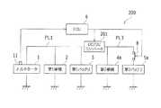
また、本実施形態では、電源ラインPL1およびPL2の間に第1スイッチ7が設けられる例を示したが、これに限らず、図5に示す変形例による車両200のように、電源ラインPL1およびPL3の間にDC/DCコンバータ201が設けられていてもよい。この場合、電源ラインPL3が電源ラインPL1に対して高圧であってもよいし、電源ラインPL3が電源ラインPL1に対して低圧であってもよく、その電源ラインPL3に接続される第2補機4aおよび第2バッテリ5aに応じて設定される。また、車両200では、電源ラインPL1にオルタネータ1が接続される例を示したが、これに限らず、電源ラインPL3にオルタネータ1が接続されていてもよい。すなわち、オルタネータ1が、第1バッテリ3側ではなく、第2バッテリ5a側に設けられていてもよい。 Further, in the present embodiment, the example in which the
また、本実施形態のフローチャートでは、オルタネータ1の温度が第1所定値Th1よりも大きい場合に、オルタネータ1の発電トルクが所定閾値を超えているか否かを判断する例を示したが、これに限らず、オルタネータの発電トルクが所定閾値を下回っている場合に、オルタネータの温度が第1所定値よりも大きいか否かを判断するようにしてもよい。すなわち、本実施形態のフローチャートは一例であってその手順に限定されるものではない。 Moreover, in the flowchart of this embodiment, when the temperature of the
また、本実施形態では、オルタネータ1の発電トルクが所定閾値を超えているか否かを判断する例を示したが、これに限らず、オルタネータの発電電流が所定閾値を超えているか否かを判断するようにしてもよい。 In the present embodiment, an example is shown in which it is determined whether or not the power generation torque of the
本発明は、エンジンの回転によって発電可能な発電機と、その発電機により充電可能な第1バッテリおよび第2バッテリとを備える車両を制御する車両の制御装置に利用可能である。 INDUSTRIAL APPLICABILITY The present invention is applicable to a vehicle control device that controls a vehicle including a generator that can generate electricity by rotating an engine, and a first battery and a second battery that can be charged by the generator.
1 オルタネータ(発電機)
3 第1バッテリ
5、5a 第2バッテリ
6 ECU(車両の制御装置)
8 第2スイッチ(開閉器)
100、200 車両1 Alternator (generator)
3
8 Second switch (switch)
100, 200 vehicles
Claims (5)
Translated fromJapanese前記発電機の負荷が高くなることが予測される場合に、前記開閉器を開くことにより、前記発電機で発電される回生電力が前記第2バッテリに充電されないように構成されていることを特徴とする車両の制御装置。A generator capable of generating electricity by rotation of the engine; and a first battery and a second battery that can be charged by the generator; the first battery being connected in parallel with the generator; A vehicle control device applied to a vehicle connected in parallel with the generator and the first battery via a switch,
When the load of the generator is predicted to increase, the regenerative power generated by the generator is not charged in the second battery by opening the switch. A vehicle control device.
前記発電機の負荷が高くなることが予測される場合に、前記発電機の発電トルクが所定閾値を超えているときに、前記開閉器を閉じたままにするように構成されていることを特徴とする車両の制御装置。The vehicle control device according to claim 1,
When the load on the generator is predicted to increase, the switch is configured to remain closed when the power generation torque of the generator exceeds a predetermined threshold. A vehicle control device.
前記発電機の負荷が高くなることが予測される場合に、前記発電機の発電トルクが前記所定閾値を下回ったときに、前記開閉器を開くように構成されていることを特徴とする車両の制御装置。The vehicle control device according to claim 2,
When the load on the generator is predicted to increase, the vehicle is configured to open the switch when the power generation torque of the generator falls below the predetermined threshold. Control device.
前記第2バッテリは、前記第1バッテリに比べて、高出力および/または高容量であることを特徴とする車両の制御装置。In the control apparatus of the vehicle as described in any one of Claims 1-3,
The vehicle control device according to claim 1, wherein the second battery has a higher output and / or a higher capacity than the first battery.
前記発電機の負荷が高くなることが予測される場合は、前記発電機の温度が所定値よりも大きい場合を含むことを特徴とする車両の制御装置。In the control apparatus of the vehicle as described in any one of Claims 1-4,
When the load of the generator is predicted to increase, the vehicle control device includes a case where the temperature of the generator is higher than a predetermined value.
Priority Applications (2)
| Application Number | Priority Date | Filing Date | Title |
|---|---|---|---|
| JP2017024734AJP6597664B2 (en) | 2017-02-14 | 2017-02-14 | Vehicle control device |
| US15/889,772US10632860B2 (en) | 2017-02-14 | 2018-02-06 | Controller for vehicle |
Applications Claiming Priority (1)
| Application Number | Priority Date | Filing Date | Title |
|---|---|---|---|
| JP2017024734AJP6597664B2 (en) | 2017-02-14 | 2017-02-14 | Vehicle control device |
Publications (2)
| Publication Number | Publication Date |
|---|---|
| JP2018133871Atrue JP2018133871A (en) | 2018-08-23 |
| JP6597664B2 JP6597664B2 (en) | 2019-10-30 |
Family
ID=63106057
Family Applications (1)
| Application Number | Title | Priority Date | Filing Date |
|---|---|---|---|
| JP2017024734AExpired - Fee RelatedJP6597664B2 (en) | 2017-02-14 | 2017-02-14 | Vehicle control device |
Country Status (2)
| Country | Link |
|---|---|
| US (1) | US10632860B2 (en) |
| JP (1) | JP6597664B2 (en) |
Cited By (1)
| Publication number | Priority date | Publication date | Assignee | Title |
|---|---|---|---|---|
| JP7730597B1 (en)* | 2024-11-01 | 2025-08-28 | 和征 榊原 | Motor drive circuit and electric vehicle |
Families Citing this family (4)
| Publication number | Priority date | Publication date | Assignee | Title |
|---|---|---|---|---|
| JP6540565B2 (en)* | 2016-03-16 | 2019-07-10 | 株式会社オートネットワーク技術研究所 | Power supply system for vehicle, drive system for vehicle |
| JP7207280B2 (en)* | 2019-11-28 | 2023-01-18 | トヨタ自動車株式会社 | vehicle controller |
| CN115447559A (en)* | 2022-08-31 | 2022-12-09 | 东风汽车集团股份有限公司 | Vehicle and water-wading power battery protection method, device and computer equipment |
| CN117294192A (en)* | 2023-09-01 | 2023-12-26 | 东风华神汽车有限公司 | Method and system for prolonging service life of generator |
Citations (5)
| Publication number | Priority date | Publication date | Assignee | Title |
|---|---|---|---|---|
| JP2008167613A (en)* | 2006-12-29 | 2008-07-17 | Toyota Motor Corp | Electric vehicle |
| JP2012165589A (en)* | 2011-02-08 | 2012-08-30 | Toyota Motor Corp | Power generation control system of vehicle |
| JP2013188101A (en)* | 2012-03-12 | 2013-09-19 | Mitsubishi Electric Corp | Apparatus, method and system for control of power supply |
| US20160089992A1 (en)* | 2014-09-30 | 2016-03-31 | Johnson Controls Technology Company | Battery system bi-stable relay control |
| US20160185240A1 (en)* | 2014-12-25 | 2016-06-30 | Toyota Jidosha Kabushiki Kaisha | Power supply apparatus |
Family Cites Families (14)
| Publication number | Priority date | Publication date | Assignee | Title |
|---|---|---|---|---|
| US5422517A (en)* | 1993-05-26 | 1995-06-06 | United Technologies Corporation | Control of electric loads during generator failure in a multi-generator system |
| CA2276821C (en)* | 1998-07-09 | 2007-11-27 | Daniele C. Brotto | Method for charging batteries |
| US7004018B2 (en)* | 2002-08-27 | 2006-02-28 | Nissan Motor Co., Ltd. | Vehicle driving force control apparatus |
| JP4974210B2 (en) | 2006-02-23 | 2012-07-11 | キャタピラー エス エー アール エル | Regenerative / power running function failure prevention device for hybrid work machines |
| JP5835095B2 (en) | 2012-05-16 | 2015-12-24 | トヨタ自動車株式会社 | Hybrid vehicle and control method of hybrid vehicle |
| WO2014063065A1 (en)* | 2012-10-19 | 2014-04-24 | Gogoro, Inc. | Battery configuration for an electric vehicle |
| US9527402B2 (en)* | 2014-01-23 | 2016-12-27 | Johnson Controls Technology Company | Switched passive architectures for batteries having two different chemistries |
| JP5880519B2 (en)* | 2013-10-21 | 2016-03-09 | トヨタ自動車株式会社 | In-vehicle electronic device |
| JP2015217692A (en)* | 2014-05-14 | 2015-12-07 | トヨタ自動車株式会社 | Power supply control device |
| JP6245094B2 (en)* | 2014-06-30 | 2017-12-13 | 日立化成株式会社 | Battery system |
| JP6191575B2 (en)* | 2014-08-06 | 2017-09-06 | トヨタ自動車株式会社 | Power supply |
| WO2017051444A1 (en)* | 2015-09-25 | 2017-03-30 | 日産自動車株式会社 | Vehicle power supply control method and vehicle power supply control device |
| BR112018069270B1 (en)* | 2016-03-22 | 2023-03-21 | Nissan Motor Co., Ltd | ENERGY SUPPLY SYSTEM AND METHOD FOR CONTROLLING THE SAME |
| JP6560713B2 (en)* | 2017-06-26 | 2019-08-14 | 株式会社Subaru | Vehicle power supply |
- 2017
- 2017-02-14JPJP2017024734Apatent/JP6597664B2/ennot_activeExpired - Fee Related
- 2018
- 2018-02-06USUS15/889,772patent/US10632860B2/ennot_activeExpired - Fee Related
Patent Citations (6)
| Publication number | Priority date | Publication date | Assignee | Title |
|---|---|---|---|---|
| JP2008167613A (en)* | 2006-12-29 | 2008-07-17 | Toyota Motor Corp | Electric vehicle |
| JP2012165589A (en)* | 2011-02-08 | 2012-08-30 | Toyota Motor Corp | Power generation control system of vehicle |
| JP2013188101A (en)* | 2012-03-12 | 2013-09-19 | Mitsubishi Electric Corp | Apparatus, method and system for control of power supply |
| US20160089992A1 (en)* | 2014-09-30 | 2016-03-31 | Johnson Controls Technology Company | Battery system bi-stable relay control |
| US20160185240A1 (en)* | 2014-12-25 | 2016-06-30 | Toyota Jidosha Kabushiki Kaisha | Power supply apparatus |
| JP2016123212A (en)* | 2014-12-25 | 2016-07-07 | トヨタ自動車株式会社 | Power supply |
Cited By (1)
| Publication number | Priority date | Publication date | Assignee | Title |
|---|---|---|---|---|
| JP7730597B1 (en)* | 2024-11-01 | 2025-08-28 | 和征 榊原 | Motor drive circuit and electric vehicle |
Also Published As
| Publication number | Publication date |
|---|---|
| US10632860B2 (en) | 2020-04-28 |
| JP6597664B2 (en) | 2019-10-30 |
| US20180229614A1 (en) | 2018-08-16 |
Similar Documents
| Publication | Publication Date | Title |
|---|---|---|
| JP6597664B2 (en) | Vehicle control device | |
| US11577713B2 (en) | Method and device for controlling hybrid vehicle | |
| US10124794B2 (en) | Vehicle and control method therefor | |
| US11518363B2 (en) | Method and device for controlling hybrid vehicle | |
| JP5307847B2 (en) | Vehicle power supply system | |
| US10377246B2 (en) | Vehicle power source | |
| JP5836068B2 (en) | Vehicle power supply device, electric vehicle | |
| JP6119725B2 (en) | Charger | |
| JP5747724B2 (en) | Vehicle and vehicle control method | |
| JP7232095B2 (en) | Control device | |
| WO2012131864A1 (en) | Electric vehicle and control method therefor | |
| CN106458217B (en) | Vehicle control device for regenerative braking system based on battery input power | |
| JP5344090B2 (en) | Vehicle regeneration control system | |
| JP7336300B2 (en) | vehicle controller | |
| JP2016016763A (en) | Power generation control device for hybrid vehicle and power generation control method for hybrid vehicle | |
| JP2020089031A (en) | Power supply control device of vehicle | |
| JP2016002877A (en) | vehicle | |
| JP6798437B2 (en) | Electric vehicle | |
| JP2012040928A (en) | Hybrid vehicle control device | |
| JP6636840B2 (en) | Hybrid vehicle control device and hybrid vehicle system | |
| JP6670176B2 (en) | Power supply for vehicles | |
| JP7222737B2 (en) | vehicle | |
| JP7332287B2 (en) | Automotive electrical system | |
| JP7204509B2 (en) | vehicle | |
| JP2020125036A (en) | Power supply system |
Legal Events
| Date | Code | Title | Description |
|---|---|---|---|
| A621 | Written request for application examination | Free format text:JAPANESE INTERMEDIATE CODE: A621 Effective date:20181016 | |
| A977 | Report on retrieval | Free format text:JAPANESE INTERMEDIATE CODE: A971007 Effective date:20190723 | |
| TRDD | Decision of grant or rejection written | ||
| A01 | Written decision to grant a patent or to grant a registration (utility model) | Free format text:JAPANESE INTERMEDIATE CODE: A01 Effective date:20190903 | |
| A61 | First payment of annual fees (during grant procedure) | Free format text:JAPANESE INTERMEDIATE CODE: A61 Effective date:20190916 | |
| R151 | Written notification of patent or utility model registration | Ref document number:6597664 Country of ref document:JP Free format text:JAPANESE INTERMEDIATE CODE: R151 | |
| LAPS | Cancellation because of no payment of annual fees |