JP2018127000A - Printing device, control method of the same, and program - Google Patents
Printing device, control method of the same, and programDownload PDFInfo
- Publication number
- JP2018127000A JP2018127000AJP2018036480AJP2018036480AJP2018127000AJP 2018127000 AJP2018127000 AJP 2018127000AJP 2018036480 AJP2018036480 AJP 2018036480AJP 2018036480 AJP2018036480 AJP 2018036480AJP 2018127000 AJP2018127000 AJP 2018127000A
- Authority
- JP
- Japan
- Prior art keywords
- data
- tag
- storage area
- mobile terminal
- printer
- Prior art date
- Legal status (The legal status is an assumption and is not a legal conclusion. Google has not performed a legal analysis and makes no representation as to the accuracy of the status listed.)
- Pending
Links
Images


Landscapes
- Accessory Devices And Overall Control Thereof (AREA)
- Information Transfer Between Computers (AREA)
Abstract
Translated fromJapaneseDescription
Translated fromJapanese本発明は、印刷装置及びその制御方法、並びにプログラムに関する。 The present invention relates to a printing apparatus, a control method therefor, and a program.
近接無線通信(非接触通信)技術の1つであるNFC(Near Field Communication)は、通信距離が非常に短いが、ユーザが様々なサービスを簡単に利用することができる技術として、様々な分野で注目を集め、実用化されている。NFCでは、通信を行う機器同士を数cm以内に近づけると自動的に無線通信が開始され、遠ざけると無線通信が終了するよう制御される。 NFC (Near Field Communication), which is one of the proximity wireless communication (non-contact communication) technologies, has a very short communication distance, but is a technology that allows users to easily use various services in various fields. It has attracted attention and has been put to practical use. In NFC, wireless communication is automatically started when devices that communicate with each other are brought within a few centimeters, and wireless communication is controlled to end when the devices are moved away from each other.
ここ数年で急速に普及してきたスマートフォンやタブレットと呼ばれるモバイル端末にもNFCの搭載が一般的になってきている。また、記憶容量は数百バイトと小さいが、NFCによるデータの読み書きが可能で、コストが数十円と非常に安価なICタグが登場している。そこで、例えばNFCによるデータの読み書き可能な安価なICタグをプリンタに装着し、プリンタがICタグに常に最新のステータスを書き込んでおく(特許文献1参照)。そして、NFCによりICタグからデータを読み込む機能を搭載したモバイル端末をプリンタに近づけることで、プリンタのステータスをICタグから読み取ってモバイル端末のディスプレイに表示する。このようにすることで、表示部が無いあるいは簡易な表示部しかないプリンタでもICタグを搭載するという僅かなコストアップのみで、ユーザがプリンタの前で簡単に当該プリンタのステータスを確認することが可能となる。 NFC has become common in mobile terminals called smartphones and tablets, which have rapidly spread in recent years. In addition, although the storage capacity is as small as several hundred bytes, IC tags that can read and write data by NFC and cost as much as several tens of yen have appeared. Therefore, for example, an inexpensive IC tag capable of reading and writing data by NFC is attached to the printer, and the printer always writes the latest status on the IC tag (see Patent Document 1). Then, by bringing a mobile terminal equipped with a function of reading data from the IC tag by NFC close to the printer, the printer status is read from the IC tag and displayed on the display of the mobile terminal. In this way, even if the printer has no display unit or only a simple display unit, the user can easily check the status of the printer in front of the printer with only a slight increase in the cost of mounting the IC tag. It becomes possible.
しかしながら、ICタグの記憶容量が小さいと、モバイル端末に送信するステータスの情報量も限られるため、詳細なステータスを送信することができないという課題がある。また、ICタグの記憶容量を増やすことで詳細なステータスを送信可能となるが、コストが高くなるという課題もある。 However, if the storage capacity of the IC tag is small, the amount of status information to be transmitted to the mobile terminal is limited, so that there is a problem that detailed status cannot be transmitted. Further, although the detailed status can be transmitted by increasing the storage capacity of the IC tag, there is a problem that the cost increases.
本発明は、上記問題に鑑みて成されたものであり、ICタグの記憶容量より大きなデータを送信することが可能となり、低コストでモバイル端末とのデータ通信が可能となる印刷装置を提供することを目的とする。 The present invention has been made in view of the above problems, and provides a printing apparatus capable of transmitting data larger than the storage capacity of an IC tag and enabling data communication with a mobile terminal at low cost. For the purpose.
上記目的を達成するために、本発明の印刷装置は、NFCタグを備える印刷装置であって、前記印刷装置でエラーが発生したことを検知する検知手段と、前記検知手段によって前記印刷装置でエラーが発生したことを検知したことに従って、前記エラーに関する情報を含む複数の画面を外部装置に表示させるための情報を前記NFCタグに書き込む書き込み手段とを有することを特徴とする。 In order to achieve the above object, a printing apparatus according to the present invention is a printing apparatus having an NFC tag, the detecting means for detecting that an error has occurred in the printing apparatus, and an error in the printing apparatus by the detecting means. And writing means for writing information for displaying on the external device a plurality of screens including information relating to the error in accordance with the detection of occurrence of the error.
本発明によれば、ICタグの記憶容量より大きなデータを送信することが可能となり、低コストで印刷装置とモバイル端末間のデータ通信が可能となる。 According to the present invention, data larger than the storage capacity of the IC tag can be transmitted, and data communication between the printing apparatus and the mobile terminal can be performed at low cost.
以下、本発明の実施の形態を図面を参照して詳細に説明する。 Hereinafter, embodiments of the present invention will be described in detail with reference to the drawings.
[第1の実施形態]
図1は、本発明の第1の実施形態に係るデータ通信システムの概略構成の一例を示すブロック図である。[First Embodiment]
FIG. 1 is a block diagram showing an example of a schematic configuration of a data communication system according to the first embodiment of the present invention.
図1において、モバイル端末100は、スマートフォンやタブレットPCなどから成り、以下の構成を備える。 In FIG. 1, the
CPU201は、ROM103のプログラム用ROM(不図示)に記憶された、メールやウェブブラウザなど様々なアプリケーションプログラムを実行する。また、CPU101は、ROM103に記憶された通信制御プログラムを読み出して実行することにより、後述する処理を実現する。さらに、CPU101は、システムバス104に接続された各種機能部を総括的に制御する。 The
RAM102は、CPU101の主メモリ、ワークエリア等として機能する。タッチパネルコントローラ(TPC)105は、タッチパネル109への画面表示やタッチ操作に対する制御を行う。3G回線コントローラ(3GC)106は、3G回線モジュール110を制御して電話回線での通信を可能にする。無線LANコントローラ(WLANC)107は、無線LANモジュール111を制御し、WiFiに代表される無線LAN通信を可能にする。 The
近接無線通信モジュール108は、代表的なものとして、NFC(Near Field Communication)がある。NFCは、近距離でのみ通信可能な電磁界を発生させて、NFCを搭載した機器同士で近接無線通信を可能にする。 A typical example of the near
CPU101、RAM102、ROM103、TPC105、3GC106、WLANC107、及び近接無線通信モジュール108は、システムバス104に接続されている。 The
図1において、プリンタ200は、LBPなどの印刷装置から成り、以下の構成を備える。 In FIG. 1, a
CPU201は、ROM203のプログラム用ROM(不図示)に記憶された制御プログラム等に基づいてシステムバス204に接続された各種機能部とのアクセスを総括的に制御する。また、CPU201は、印刷部I/F205を介して印刷機構部220に出力情報としての画像信号を出力する。さらに、CPU201は、ROM203に記憶された通信制御プログラムを読み出して実行することにより、後述する処理を実現する。 The
RAM202は、CPU201の主メモリ、ワークエリア等として機能し、図示しない増設ポートに接続されるオプションRAMによりメモリ容量を拡張することができるように構成されている。なお、RAM202は、外部から受信した画像データを格納しておくためのメモリとして、またはビデオ信号ON/OFF情報格納領域として、その他のワーク領域等に用いられる。 The
操作パネル230は、プリンタ200を操作するためのキーやプリンタ200の状態を簡易表示するためのLEDなどで構成される。メモリコントローラ(MC)206は、外部から受信した印刷データ等を記憶するハードディスク(HDD)207とのアクセスを制御する。 The
ICタグ242は、近接無線通信モジュール241を備え、一定量のデータを記憶することが可能なNFCタグであり、上述したNFCなどの近接無線通信により、外部機器からICタグ242へのデータの読み書きができる。CPU201は、ICタグI/F240を経由してICタグ242に対してデータの読み書きができる。なお、ICタグ242は、操作パネル230に配置されている。 The
CPU201、RAM202、ROM203、ICタグI/F240、印刷部I/F205、操作パネル230、及びMC206は、システムバス204に接続されている。 The
図2は、図1のデータ通信システムにて近接無線通信を利用したデータ通信制御の概要を示す図である。 FIG. 2 is a diagram showing an outline of data communication control using proximity wireless communication in the data communication system of FIG.
図2において、データ通信部301は、近接無線通信モジュール108によりプリンタ200の近接無線通信モジュール241と近接無線通信を行い、ICタグ242(内のメモリ)に対してデータの読み書きを行うソフトウェアモジュールである。一方、データ通信部302は、ICタグI/F240により、ICタグ242(内のメモリ)に対してデータの読み書きを行うソフトウェアモジュールである。 In FIG. 2, a
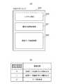
図3(a)は、ICタグ242(内のメモリ)における記憶領域の仕様(メモリマップ)を示す図である。 FIG. 3A is a diagram showing the specifications (memory map) of the storage area in the IC tag 242 (internal memory).
図3(a)において、ICタグ242(内のメモリ)には、システム領域400、通信状態格納領域401、送信データ格納領域402が設けられている。 In FIG. 3A, a
システム領域400は、ICタグを管理および制御する上で必要なメモリ領域である。 The
通信状態格納領域401は、データ転送時のハンドシェークを実現するための値が格納されるメモリ領域である。この通信状態格納領域401に格納される格納値(フラグ)の一例を図3(b)に示す。図示の格納値のうちの何れかが格納される。図示例では、格納値「0」が「送信データ先頭ブロック書き込み」、格納値「1」が「送信データ継続ブロック書き込み」、格納値「2」が「データ受信済」を表す。なお、格納値とその通信制御に関する意味合いは、図示例に限定されるものではない。このように、通信制御におけるハンドシェークに、ICタグ242の記憶領域の一部が使用される。 The communication
送信データ格納領域402は、データ転送における送信データまたは受信データが格納されるメモリ領域である。 The transmission
上述した送信データ格納領域402(第1の記憶領域)と通信状態格納領域401(第2の記憶領域)は、CPU201により作成されるように構成してもよいし、予め作成されていてもよい。 The transmission data storage area 402 (first storage area) and the communication state storage area 401 (second storage area) described above may be configured to be created by the
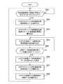
次に、プリンタ200のデータ通信部302における通信制御の流れを図4を用いて説明する。 Next, the flow of communication control in the
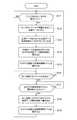
図4は、プリンタ200のデータ通信部302における通信制御の流れを示すフローチャートである。なお、データ通信部302における通信制御の主体となるものはCPU201である。 FIG. 4 is a flowchart showing a flow of communication control in the
ステップS11では、CPU201は、プリンタ200のステータスが変化したかどうか判定する。例えば、印刷中に紙詰まりが発生したなど、プリンタ200の状態が変化するのを待つ。プリンタ200のステータス変化を検知した場合、ステップS12へ進み、CPU201は、モバイル端末100に送信するプリンタ200のステータス情報を生成する。このステータス情報がモバイル端末100への送信データとなる。 In step S11, the
次に、ステップS13では、CPU201は、ステップS12で生成した送信データを、ICタグ242の送信データ格納領域402に格納可能なサイズの複数のデータブロックに分割する。このデータブロックのサイズは、ICタグ242の送信データ格納領域402に格納できるサイズであれば、どのようなサイズであってもよい。 Next, in step S13, the
次に、ステップS14では、CPU201は、分割された複数のデータブロックの先頭のデータブロックをICタグ242の送信データ格納領域402に書き込む。そして、同時に、CPU201は、ICタグ242の通信状態格納領域401に「0」を書き込む(ステップS15)。「0」という格納値は、図3(b)に示した通り「送信データ先頭ブロックの書き込み」を意味する。 Next, in step S <b> 14, the
次に、ステップS16では、CPU201は、分割された複数のデータブロックのうち、次に送信するデータブロックがあるかどうかを判定する。次に送信するデータブロックが無い、すなわち分割された複数のデータブロックの最終のデータブロックを送信データ格納領域402に書き込んでいた場合、ステップS11へ戻り、プリンタ200のステータスが変化するのを待つ。 Next, in step S <b> 16, the
一方、ステップS16で、次に送信するデータブロックがある場合は、ステップS17へ進み、CPU201は、ICタグ242の通信状態格納領域401の値が「2」になるのをポーリングして待つ。「2」という格納値は、ステップS14で書き込まれたデータブロックをモバイル端末100が受信したときに書き込まれる値であり、データブロックがモバイル端末100により受信されたことを意味する。このように、データブロックがICタグ242に書き込まれた後、通信状態格納領域401の値がポーリングされ、モバイル端末100がデータブロックを受信したことを確認してから次の送信を行うことで、データ転送におけるハンドシェークを実現している。 On the other hand, if there is a data block to be transmitted next in step S16, the process proceeds to step S17, and the
ステップS17で通信状態格納領域401の値が「2」になった場合、つまり前回のデータブロックをモバイル端末100が受信した場合にはステップS18に進む。 When the value of the communication
ステップS18では、CPU201は、次に送信するデータブロックをICタグ242の送信データ格納領域402に書き込む(上書き)。そして、同時に、ステップS19では、CPU201は、ICタグ242の通信状態格納領域401に「1」を書き込む。「1」という格納値は、図3(b)に示した通り、「送信データ継続ブロックの書き込み」を意味する。 In step S18, the
このように、分割された複数のデータブロックの全てを送信するまで、ステップS16からステップS19までを繰り返すことにより、プリンタ200のステータス情報(ステータスデータ)をモバイル端末100に送信する。 In this way, the status information (status data) of the
なお、送信データ格納領域402にデータブロックを書き込む場合はデータブロックの上書きであってもよい。また、ICタグ242の通信状態格納領域401の値が「2」に更新されたときに、送信データ格納領域402のデータをクリアし、データブロックを送信データ格納領域402に書き込むように構成してもよい。 When writing a data block in the transmission
次に、モバイル端末100のデータ通信部301における通信制御の流れを図5を用いて説明する。 Next, the flow of communication control in the
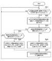
図5は、モバイル端末100のデータ通信部301における通信制御の流れを示すフローチャートである。なお、データ通信部301における通信制御の主体となるものはCPU101である。 FIG. 5 is a flowchart showing a flow of communication control in the
まず、ステップS21では、CPU101は、モバイル端末100がプリンタ200のICタグ242にタッチされ(近づけられ)、近接無線通信で通信が可能になるまで待機する。近接無線通信で通信が可能となった場合は、ステップS22に進み、CPU101は、ICタグ242の通信状態格納領域401に格納されている値と送信データ格納領域402に格納されているデータブロックを読み込む。 First, in step S <b> 21, the
次に、ステップS23では、CPU101は、ステップS22で取得した通信状態格納領域401の値が「0」であるかどうか判定する。通信状態格納領域401の値が「0」であった場合は、ステップS24へ進む一方、「0」でなかった場合は、ステップS25へ進む。 Next, in step S23, the
ステップS24では、CPU101は、送信データ格納領域402から読み取ったデータブロックを、送信データの先頭ブロック(第一のステータスデータ)として保存する。 In step S24, the
次に、ステップS27では、CPU101は、データブロックを受信したことをプリンタ200へ通知するために、ICタグ242の通信状態格納領域401に「データ受信済」であることを示す「2」を書き込み(更新)、ステップS21へ戻る。 Next, in step S27, the
ステップS25では、CPU101は、ステップS22で取得した通信状態格納領域401の値が「1」であるかどうか判定する。通信状態格納領域401の値が「1」であった場合は、ステップS26に進む一方、通信状態格納領域401の値が「1」でなかった場合はステップS21へ戻る。すなわち、通信状態格納領域401の値が「0」でも「1」でもない場合は、モバイル端末100からの新規送信のデータは無いという判断してステップS21へ戻る。 In step S25, the
ステップS26では、CPU101は、送信データ格納領域402から読み取ったデータブロックを、先頭以外の継続するデータブロック(第二、第三、第四、・・・のステータスデータ)として保存して、ステップS27へ進む。なお、保存されたデータブロックは、ステータス情報が分割されたものであることから、合成して元のステータス情報として保存し直すように構成してもよい。 In step S26, the
一方、プリンタ200は、分割されたデータブロックをICタグ242に書き込んだ後、モバイル端末100が当該データを受信するのをポーリングして待つ。そして、モバイル端末100が当該データを受信したことを確認すると、次のデータブロックをICタグ242に書き込む。その結果、モバイル端末100をプリンタ200のICタグ242にタッチする度に、プリンタ200から、分割されたステータス情報(ステータスデータ)を順次受信することができる。 On the other hand, after writing the divided data block into the
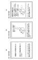
次に、上記方法によりプリンタ200から取得したステータス情報をモバイル端末100で表示するときの表示方法について説明する。本実施形態では、プリンタ200に紙詰まり(ジャム)が発生した場合について図6(a)〜図6(c)を用いて説明する。 Next, a display method when displaying the status information acquired from the
まず、1回目のタッチでは、モバイル端末100は、プリンタ200のメインとなるステータス情報を取得してタッチパネル109に表示する。例えば、図6(a)に示すように、第一の表示画面として、「紙詰まりが発生しました」との表示を行い、画面下部に次にタッチした場合の説明を表示している。 First, in the first touch, the
2回目のタッチでは、モバイル端末100は、メインステータスに対する詳細情報を取得してタッチパネル109の表示画面を切り替える。図6(b)では、第二の表示画面として紙詰まりの発生場所を示す情報を表示している。そして、もう一度タッチ(3回目のタッチ)すると、さらに次の情報を取得してタッチパネル109の表示画面を切り替える。図6(c)では、第三の表示画面として、今回発生した紙詰まりの解除方法を表示している。このように、プリンタ200(のICタグ242)にモバイル端末100をタッチさせる度に、ステータス情報の表示が更新されるので、表示すべき情報量が多い場合でも、無理なく表示することが可能となる。 In the second touch, the
なお、上記の場合、分割された送信データのうち、先頭のデータブロックが第一の表示画面に表示されるデータとなるように、送信データが分割されることが好ましいが、この限りではない。また、2回目のタッチでモバイル端末100が取得したデータが第二の表示画面となるようにし、3回目のタッチでモバイル端末100が受信したデータが第三の表示画面となるようにすることが好ましいが、この限りではない。 In the above case, it is preferable that the transmission data is divided so that the first data block among the divided transmission data is the data displayed on the first display screen, but this is not restrictive. Further, the data acquired by the
以上説明したように、プリンタでは、プリンタのステータス情報(ステータスデータ)をICタグの送信データ格納領域に格納できるサイズに分割し、分割された複数のデータをICタグの通信状態格納領域の値(フラグ)に応じて送信データ格納領域に書き込む。一方、モバイル端末がプリンタ(のICタグ)にタッチされる度に、ICタグから送信データ格納領域のデータを取得し、通信状態格納領域の値を書き換える。これにより、ICタグの記憶容量より大きなデータを送信することが可能となり、低コストで印刷装置とモバイル端末間のデータ通信が可能となる。 As described above, in the printer, the printer status information (status data) is divided into sizes that can be stored in the transmission data storage area of the IC tag, and the divided pieces of data are divided into values (in the communication status storage area of the IC tag ( Write to the transmission data storage area according to the flag. On the other hand, every time the mobile terminal is touched by the printer (IC tag), the data in the transmission data storage area is acquired from the IC tag, and the value in the communication state storage area is rewritten. Thereby, data larger than the storage capacity of the IC tag can be transmitted, and data communication between the printing apparatus and the mobile terminal can be performed at low cost.
[第2の実施形態]
上記第1の実施形態では、モバイル端末100をプリンタ200のICタグ242にタッチさせる度に、分割したステータスデータをプリンタ200からモバイル端末100へ送信する方法について説明した。[Second Embodiment]
In the first embodiment, the method of transmitting the divided status data from the
本第2の実施形態では、モバイル端末100をプリンタ200のICタグ242にタッチしたままで、分割されたステータスデータを送信する方法について図7を参照して説明する。なお、図1〜図3に示す構成とプリンタ200における処理動作が上記第1の実施の形態と同じであるので、それらの説明を省略し、異なる点のみを説明する。 In the second embodiment, a method for transmitting divided status data while the
図7は、本発明の第2の実施形態におけるモバイル端末100のデータ通信部301における通信制御の流れを示すフローチャートである。なお、図7におけるステップS31からステップS37までは、図5におけるステップS21からステップS37までと同じであるため、それらの説明は省略する。 FIG. 7 is a flowchart illustrating a flow of communication control in the
ステップS38では、CPU101は、プリンタ200との間の近接無線通信が継続して通信可能状態にあるか、つまりモバイル端末100がプリンタ200のICタグ242にタッチされたままであるかどうか判定する。近接無線通信が切断されていた場合はステップS31へ戻り、再びタッチされるのを待つ一方、継続して通信可能である場合はステップS39へ進む。 In step S <b> 38, the
ステップS39では、CPU101は、ICタグ242の通信状態格納領域401の値を読み込む。 In step S39, the
次に、ステップS40では、CPU101は、ステップS39で読み込んだ値が「2」以外になったか判定する。「2」以外になった場合、つまり「0」か「1」になった場合は、次のデータブロックがICタグ242の送信データ格納領域402に格納されたと判断して、ステップS32へ戻る。 Next, in step S40, the
一方、ステップS39で読み込んだ値が「2」であった場合は、ステップS38へ戻る。つまり、プリンタ200との間の近接無線通信が可能である間は、ICタグ242の通信状態格納領域401の値をポーリングして「2」以外に変わり、送信データ格納領域402に次のデータブロックが書き込まれるのを待つ。 On the other hand, if the value read in step S39 is “2”, the process returns to step S38. That is, while close proximity wireless communication with the
このように、モバイル端末100をプリンタ200のICタグ242にタッチし続けることで、分割された複数のデータブロックを連続してプリンタ200から受信することができる。 In this way, by continuously touching the
本第2の実施形態では、プリンタ200のICタグ242にモバイル端末100を一度タッチさせるだけで、ICタグ242から所定のサイズに分割されたステータス情報を連続して読み込むことができる。そのため、プリンタ200から受信したステータス情報をモバイル端末100で表示する場合、例えば、図6(a)に示す第一の表示画面から図6(c)に示す第三の表示画面までを、画面をフリックすることで表示変更させることができる。なお、一画面に全部表示して画面スクロールできるように構成してもよい。 In the second embodiment, the status information divided into a predetermined size can be continuously read from the
以上説明したように、モバイル端末を何度もプリンタのICタグにタッチしなくても、タッチしたままでICタグから送信データ格納領域のデータを取得することが可能となる。これにより、上記第1の実施形態における効果に加えて、モバイル端末を繰り返しプリンタにタッチさせることがなくなり、ユーザの利便性を向上させることが可能となる。 As described above, it is possible to acquire data in the transmission data storage area from the IC tag without touching the IC tag of the printer many times without touching the mobile terminal. Thereby, in addition to the effect in the first embodiment, the mobile terminal is not repeatedly touched to the printer, and the convenience of the user can be improved.
[第3の実施形態]
上記第1及び第2の実施形態では、プリンタ200からモバイル端末100へデータの送信する場合について説明したが、モバイル端末100からプリンタ200へのデータの送信も可能である。例えば、図4で説明したプリンタ200における処理をモバイル端末100で実行させ、図5で説明したモバイル端末100における処理をプリンタ200で実行させる。この場合、送信データを、図4で説明したプリンタ200のステータス情報からモバイル端末100のステータス情報に変更してもよいし、印刷データ等に変更してもよい。[Third Embodiment]
In the first and second embodiments, the case where data is transmitted from the
第3の実施形態によれば、プリンタからモバイル端末へのデータ送信時だけでなく、モバイル端末からプリンタへのデータ送信時においても、ICタグの記憶容量以上のサイズのデータを送信することが可能となる。その結果、近接無線通信によりモバイル端末からプリンタに印刷データを容易に送信して、印刷を実行させることができる。 According to the third embodiment, it is possible to transmit data having a size larger than the storage capacity of the IC tag not only when transmitting data from the printer to the mobile terminal but also when transmitting data from the mobile terminal to the printer. It becomes. As a result, it is possible to easily transmit print data from the mobile terminal to the printer by proximity wireless communication and execute printing.
[第4の実施形態]
上記第1の実施形態では、モバイル端末100をプリンタ200のICタグ242へタッチする度に、分割されたステータスデータをプリンタ200からモバイル端末100へ送信する方法について説明した。この方法では、プリンタ200のICタグ242へのタッチを複数回行う間に、他のモバイル端末がプリンタ200のICタグ242にタッチしてしまうと、当該他のモバイル端末からのデータ受信を開始してしまう。その結果、他のモバイル端末から、分割された複数のデータブロックのうちの先頭のデータブロックが受信されず、途中のデータブロックが受信(および表示)されてしまうことになる。また、他のモバイル端末によるタッチの後にモバイル端末100のタッチが行われると、他のモバイル端末からデータブロックを受信することになり、継続して受信すべきデータブロックが受信できなくなる。この場合、例えば図6(b)に示す第二の表示画面や図6(c)に示す第三の表示画面が表示されないおそれがある。[Fourth Embodiment]
In the first embodiment, the method of transmitting the divided status data from the
本第3の実施形態では、モバイル端末を識別するための識別IDとデータの送信履歴情報を用いて、複数のモバイル端末にステータスデータを正しく送信する方法について説明する。なお、図1、図2に示す構成が上記第1の実施の形態と同じであるので、それらの説明を省略し、異なる点のみを説明する。 In the third embodiment, a method of correctly transmitting status data to a plurality of mobile terminals using an identification ID for identifying a mobile terminal and data transmission history information will be described. The configuration shown in FIGS. 1 and 2 is the same as that of the first embodiment, so that the description thereof will be omitted and only different points will be described.
図8は、本発明の第4の実施形態におけるICタグ242(内のメモリ)の記憶領域の仕様(メモリマップ)を示す図である。 FIG. 8 is a diagram showing the specification (memory map) of the storage area of the IC tag 242 (internal memory) in the fourth embodiment of the present invention.
図8において、ICタグ242には、システム領域400、モバイル端末通信状態格納領域501、モバイル端末識別情報格納領域502、送信データ通信状態格納領域503、及び送信データ格納領域402が設けられている。 In FIG. 8, the
モバイル端末通信状態格納領域501は、モバイル端末100の通信状態を示す値が格納されるメモリ領域である。このモバイル端末通信状態格納領域501に格納される格納値(フラグ)の一例を図9(a)に示す。図示の格納値のうちの何れかが格納される。図示例では、格納値「0」が「通信終了」、格納値「1」が「通信開始」を表す。 The mobile terminal communication
モバイル端末識別情報格納領域502は、ICタグ242と通信が可能となったモバイル端末の識別情報が格納されるメモリ領域である。ここでモバイル端末の識別情報は、例えば機体番号(シリアル番号)やネットワーク機器としてのMACアドレスなど、機体が識別可能な情報であればよい。 The mobile terminal identification
送信データ通信状態格納領域503は、データ送信時のハンドシェークを実現するための値が格納されるメモリ領域である。この送信データ通信状態格納領域に格納される格納値(フラグ)の一例を図9(b)に示す。図示の格納値のうちの何れかが格納される。図示例では、格納値「0」が「データ受信済」、格納値「1」が「送信データ書き込み」を表す。 The transmission data communication
図9(c)は、プリンタ200のRAM202に格納されるデータ送信履歴テーブルの内容を示す図である。 FIG. 9C shows the contents of the data transmission history table stored in the
データ送信履歴テーブルは、各モバイル端末の識別情報と、送信済のデータブロックのブロック番号(識別情報)とを対応させたデータテーブルである。 The data transmission history table is a data table in which identification information of each mobile terminal is associated with a block number (identification information) of a transmitted data block.
次に、プリンタ200のデータ通信部302における通信制御の流れを図10を用いて説明する。 Next, the flow of communication control in the
図10は、プリンタ200のデータ通信部302における通信制御の流れを示すフローチャートである。なお、データ通信部302における通信制御の主体となるものはCPU201である。 FIG. 10 is a flowchart showing a flow of communication control in the
まず、ステップS41では、CPU201は、プリンタ200からモバイル端末100への送信データが新規に発生したか、もしくは送信データが更新されたかどうか判定する。送信データが新規もしくは更新された場合は、ステップS42に進む一方、送信データが新規に発生せず、また送信データの更新が無いと判断した場合は、ステップS44に進む。 First, in step S41, the
ステップS42では、CPU201は、送信データをICタグ242の送信データ格納領域402に格納可能なサイズの複数のデータブロックに分割する。 In step S <b> 42, the
次に、ステップS43では、CPU201は、RAM202に格納されているデータ送信履歴テーブルのデータをクリアし、ステップS44へ進む。これは、いかなるモバイル端末にも新規の送信データを、当該送信データを分割したデータブロックの先頭のデータブロックから送信するためである。 Next, in step S43, the
ステップS44では、CPU201は、ICタグ242のモバイル端末通信状態格納領域501の値を定期的に読み込み、通信が開始されるのを待つ。つまり、プリンタ200のICタグ242にモバイル端末がタッチされ通信可能となるのを待つ。モバイル端末と通信が可能になると、ステップS45へ進み、ICタグ242のモバイル端末識別情報格納領域502の値を読み込み、モバイル端末の識別情報を取得する。 In step S44, the
次に、ステップS46では、CPU201は、データ送信履歴テーブルを検索し、ステップS45で取得したモバイル端末の識別情報と一致するものが存在するかどうか判定する。検索した結果、取得したモバイル端末の識別情報と一致するものが存在した場合、ステップS47へ進む一方、そうでない場合には、ステップS49へ進む。 Next, in step S46, the
ステップS47では、CPU201は、データ送信履歴テーブルから、モバイル端末の識別情報に対応する送信済のデータブロックのブロック番号を読み出し、当該ブロック番号の次のブロック番号に対応するデータブロックを送信するデータに決定する。 In step S47, the
次に、ステップS48では、CPU201は、データ送信履歴テーブルの送信済のデータブロックのブロック番号を更新して(今回送信するデータブロックを、送信済みの送信データブロック番号とする)、ステップS51へ進む。 Next, in step S48, the
ステップS49では、CPU201は、分割された複数のデータブロックのうち、先頭のデータブロックを送信するデータに決定する。 In step S49, the
次に、ステップS50では、CPU201は、データ送信履歴テーブルに、モバイル端末の識別情報と送信済みのデータブロックのブロック番号を書き込む。 Next, in step S50, the
ステップS51では、CPU201は、ICタグ242の送信データ通信状態格納領域503の値が「0」(データ受信済み)になるのをポーリングして待つ。 In step S51, the
ステップS52では、CPU201は、ステップS47またはステップS49で決定したデータブロックをICタグ242の送信データ格納領域402に書き込む。 In step S52, the
次に、ステップS53では、CPU201は、ICタグ242の送信データ通信状態格納領域503に「送信データ書き込み」を示す「1」を書き込む。 Next, in step S <b> 53, the
次に、ステップS54では、CPU201は、ICタグ242のモバイル端末通信状態格納領域501の値を定期的に読み込み、当該値が「通信終了」を示す「0」になるのを待つ。ICタグ242のモバイル端末通信状態格納領域501の値が「0」になったときは、再びステップS41に戻り、送信データの確認、そしてモバイル端末100がICタグ242にタッチされるのを(通信可能となるのを)待つ。 Next, in step S54, the
なお、上記処理において、分割された複数のデータブロックのうち、次に送信するデータブロックがあるかどうかを判定し、次に送信するデータブロックがない場合には、ステップS41に戻るように構成されているものとする。 In the above processing, it is determined whether or not there is a data block to be transmitted next among the plurality of divided data blocks, and when there is no data block to be transmitted next, the process returns to step S41. It shall be.
次に、モバイル端末100のデータ通信部301における通信制御の流れを図11を用いて説明する。 Next, the flow of communication control in the
図11は、モバイル端末100のデータ通信部301における通信制御の流れを示すフローチャートである。なお、データ通信部301における通信制御の主体となるものはCPU101である。 FIG. 11 is a flowchart showing a flow of communication control in the
まず、ステップS61では、CPU101は、自機(モバイル端末100)がプリンタ200のICタグ242にタッチされ(近づけられ)、近接無線通信で通信が可能になるのを待機する。近接無線通信で通信が可能となった場合は、ステップS62に進み、CPU101は、ICタグ242のモバイル端末通信状態格納領域501に「通信開始」を示す「1」を書き込む。 First, in step S <b> 61, the
次に、ステップS63では、CPU101は、ICタグ242のモバイル端末識別情報格納領域502に自機(モバイル端末)の識別情報を書き込む。 Next, in step S <b> 63, the
次に、ステップS64では、CPU101は、ICタグ242の送信データ通信状態格納領域503の値を読み込む。そして、ステップS65では、CPU101は、ステップS64で読み込んだ値が「送信データ書き込み」を示す「1」であるかを判定する。ステップS64で読み込んだ値が「1」でなかった場合はステップS64へ戻り、ICタグ242の送信データ通信状態格納領域503の値が「1」になるまで待つ。つまり、ICタグ242の送信データ格納領域402にデータブロックが書き込まれるのを待つ。 Next, in step S64, the
ステップS65でデータブロックが書き込まれたと判定した場合はステップS66へ進み、CPU101は、ICタグ242の送信データ格納領域402のデータを読み込んで保存する。 If it is determined in step S65 that the data block has been written, the process proceeds to step S66, and the
次に、ステップS67では、CPU101は、ICタグ242のモバイル端末通信状態格納領域501に「通信終了」を示す「0」を書き込む。 Next, in step S <b> 67, the
次に、ステップS68では、CPU101は、ICタグ242の送信データ通信状態格納領域503に「データ受信済み」を示す「0」を書き込んだ後、ステップS61へ戻り、再度ICタグ242にタッチされ(近づけられ)、通信が可能となるのを待つ。 Next, in step S68, the
以上説明したように、プリンタでは、モバイル端末識別情報格納領域に格納された識別情報と一致するものがデータ送信履歴テーブルに存在する場合には、送信履歴情報を更新する。そして、送信データ通信状態格納領域に格納されたフラグが送信済みに更新される度に、分割された複数のデータブロックのうち、送信履歴テーブルに基づいて決定されるデータブロックを1つずつ送信データ格納領域に格納する。一方、モバイル端末識別情報格納領域に格納された識別情報と一致するものが送信履歴テーブルに存在しなかった場合、送信履歴テーブルに送信履歴を書きみ、分割された複数のデータブロックの先頭のデータブロックを送信データ格納領域に格納する。 As described above, the printer updates the transmission history information when the data transmission history table matches the identification information stored in the mobile terminal identification information storage area. Each time the flag stored in the transmission data communication state storage area is updated to be transmitted, one data block determined based on the transmission history table is transmitted one by one from among the plurality of divided data blocks. Store in the storage area. On the other hand, if there is no data in the transmission history table that matches the identification information stored in the mobile terminal identification information storage area, the transmission history is written in the transmission history table, and the first data of the divided data blocks Store the block in the transmission data storage area.
モバイル端末は、ICタグとの間で近接無線通信が開始される度に、モバイル端末識別情報格納領域に自装置の識別情報を格納し、送信データ格納領域に格納されたデータブロックを読み込む。そして、データブロックを読み込む度に、送信データ通信状態格納領域に格納されたフラグを送信済みに更新する。 Each time close proximity wireless communication is started with an IC tag, the mobile terminal stores its own identification information in the mobile terminal identification information storage area, and reads the data block stored in the transmission data storage area. Each time the data block is read, the flag stored in the transmission data communication state storage area is updated to “transmitted”.
上記構成により、プリンタとモバイル端末との間で全データブロックの送信が完了していない状態で、他のモバイル端末が割り込んでICタグへのタッチが行われても、各モバイル端末に対して正しい順番でデータ抜けもなく、データを送信することが可能となる。 With the above configuration, even when another mobile terminal interrupts and touches the IC tag in a state where transmission of all data blocks is not completed between the printer and the mobile terminal, each mobile terminal is correct. Data can be transmitted without any missing data in order.
なお、上記第4の実施形態では、データ送信履歴テーブルをプリンタ200のRAM202に格納する構成を説明したが、ICタグ242に格納するように構成してもよい。 In the fourth embodiment, the data transmission history table is stored in the
上記第1〜第4の実施形態では、通信状態格納領域、モバイル端末通信状態格納領域、モバイル端末識別情報格納領域、送信データ通信状態格納領域がICタグ側に作成される構成について説明したが、装置本体側に作成するように構成してもよい。これにより、ICタグに記憶できるデータ量を増加させて、繰り返し近接させる回数を減らしたり、データ送信頻度を減らせることができる。 In the first to fourth embodiments described above, the communication state storage area, the mobile terminal communication state storage area, the mobile terminal identification information storage area, and the transmission data communication state storage area are created on the IC tag side. You may comprise so that it may produce on the apparatus main body side. As a result, the amount of data that can be stored in the IC tag can be increased, and the number of times of repeated proximity can be reduced, or the data transmission frequency can be reduced.
また、本発明は、以下の処理を実行することによっても実現される。即ち、上述した実施形態の機能を実現するソフトウェア(プログラム)を、ネットワーク又は各種記憶媒体を介してシステム或いは装置に供給し、そのシステム或いは装置のコンピュータ(またはCPUやMPU等)がプログラムを読み出して実行する処理である。 The present invention can also be realized by executing the following processing. That is, software (program) that realizes the functions of the above-described embodiments is supplied to a system or apparatus via a network or various storage media, and a computer (or CPU, MPU, or the like) of the system or apparatus reads the program. It is a process to be executed.
100 モバイル端末
101,201 CPU
108,241 近接無線通信モジュール
200 プリンタ
242 ICタグ
301,302 データ通信部
401 通信状態格納領域
402 送信データ格納領域100
108, 241 Proximity
Claims (7)
Translated fromJapanese前記印刷装置でエラーが発生したことを検知する検知手段と、
前記検知手段によって前記印刷装置でエラーが発生したことを検知したことに従って、前記エラーに関する情報を含む複数の画面を外部装置に表示させるための情報を前記NFCタグに書き込む書き込み手段とを有することを特徴とする印刷装置。A printing apparatus equipped with an NFC tag,
Detecting means for detecting that an error has occurred in the printing apparatus;
Writing means for writing information for displaying on the external device a plurality of screens including information relating to the error according to the detection means detecting that an error has occurred in the printing apparatus. Characteristic printing device.
前記印刷装置でエラーが発生したことを検知し、
前記印刷装置でエラーが発生したことを検知したことに従って、前記エラーに関する情報を含む複数の画面を外部装置に表示させるための情報を前記NFCタグに書き込むことを特徴とする印刷装置の制御方法。A method for controlling a printing apparatus including an NFC tag,
Detecting that an error has occurred in the printing device,
A method for controlling a printing apparatus, comprising: writing information for causing an external apparatus to display a plurality of screens including information relating to the error in the NFC tag according to detection of an error occurring in the printing apparatus.
Priority Applications (1)
| Application Number | Priority Date | Filing Date | Title |
|---|---|---|---|
| JP2018036480AJP2018127000A (en) | 2018-03-01 | 2018-03-01 | Printing device, control method of the same, and program |
Applications Claiming Priority (1)
| Application Number | Priority Date | Filing Date | Title |
|---|---|---|---|
| JP2018036480AJP2018127000A (en) | 2018-03-01 | 2018-03-01 | Printing device, control method of the same, and program |
Related Parent Applications (1)
| Application Number | Title | Priority Date | Filing Date |
|---|---|---|---|
| JP2014040336ADivisionJP6300575B2 (en) | 2014-03-03 | 2014-03-03 | Data communication system, data communication method, and program |
Related Child Applications (1)
| Application Number | Title | Priority Date | Filing Date |
|---|---|---|---|
| JP2019144699ADivisionJP6746764B2 (en) | 2019-08-06 | 2019-08-06 | Communication system, printing apparatus, control method thereof, and program |
Publications (1)
| Publication Number | Publication Date |
|---|---|
| JP2018127000Atrue JP2018127000A (en) | 2018-08-16 |
Family
ID=63171880
Family Applications (1)
| Application Number | Title | Priority Date | Filing Date |
|---|---|---|---|
| JP2018036480APendingJP2018127000A (en) | 2018-03-01 | 2018-03-01 | Printing device, control method of the same, and program |
Country Status (1)
| Country | Link |
|---|---|
| JP (1) | JP2018127000A (en) |
Citations (4)
| Publication number | Priority date | Publication date | Assignee | Title |
|---|---|---|---|---|
| JP2008276693A (en)* | 2007-05-07 | 2008-11-13 | Konica Minolta Business Technologies Inc | Image forming device and program |
| JP2009184225A (en)* | 2008-02-06 | 2009-08-20 | Seiko Epson Corp | System comprising information processing device and reader terminal, control method for the system, control program for the system, and information processing device |
| WO2013095409A1 (en)* | 2011-12-21 | 2013-06-27 | Intel Corporation | Near field communications-triggering for wireless display/docking |
| JP2013187567A (en)* | 2012-03-05 | 2013-09-19 | Canon Inc | Information processing device, method for controlling information processing device, and program |
- 2018
- 2018-03-01JPJP2018036480Apatent/JP2018127000A/enactivePending
Patent Citations (4)
| Publication number | Priority date | Publication date | Assignee | Title |
|---|---|---|---|---|
| JP2008276693A (en)* | 2007-05-07 | 2008-11-13 | Konica Minolta Business Technologies Inc | Image forming device and program |
| JP2009184225A (en)* | 2008-02-06 | 2009-08-20 | Seiko Epson Corp | System comprising information processing device and reader terminal, control method for the system, control program for the system, and information processing device |
| WO2013095409A1 (en)* | 2011-12-21 | 2013-06-27 | Intel Corporation | Near field communications-triggering for wireless display/docking |
| JP2013187567A (en)* | 2012-03-05 | 2013-09-19 | Canon Inc | Information processing device, method for controlling information processing device, and program |
Similar Documents
| Publication | Publication Date | Title |
|---|---|---|
| CN100368970C (en) | Information processing method, information processing apparatus, and image output apparatus | |
| US20120235897A1 (en) | Information processing apparatus, and control method and program therefor | |
| CN109978490A (en) | Pass through the system and method for the collaborative share page | |
| KR20150032066A (en) | Method for screen mirroring, and source device thereof | |
| CN103294339A (en) | Image display device and method of controlling the same | |
| US11082480B2 (en) | File information system management system and method | |
| CN109769089B (en) | Image processing method and terminal equipment | |
| JP2005100050A (en) | Information display system and method | |
| JP5585721B2 (en) | Information device, screen switching method, and screen switching program | |
| CN105095233A (en) | Local web image updating method, device and system | |
| US11681410B2 (en) | Icon management method and terminal device | |
| CN102625015B (en) | Image forming apparatus and terminal device each having touch panel | |
| JP6078625B1 (en) | Advertisement processing apparatus and program | |
| JP6602190B2 (en) | Software development program and software development method | |
| JP6746764B2 (en) | Communication system, printing apparatus, control method thereof, and program | |
| CN101997905A (en) | Computer system and control method thereof | |
| JP2015172872A (en) | Information processing device and control method thereof, computer program, information processing system, and image forming apparatus | |
| CN116391170A (en) | Electronic device, display device and control method thereof | |
| JP6300575B2 (en) | Data communication system, data communication method, and program | |
| JP2018127000A (en) | Printing device, control method of the same, and program | |
| WO2018003213A1 (en) | Information processing device, display device, method for controlling information processing device, and information processing program | |
| JP2009204844A (en) | Information provision apparatus, its control method, and program | |
| CN106970812B (en) | Upgrade file processing device and terminal | |
| US10311684B2 (en) | Display system, display device, and display method | |
| JP4742888B2 (en) | Server device, client device, and program |
Legal Events
| Date | Code | Title | Description |
|---|---|---|---|
| A131 | Notification of reasons for refusal | Free format text:JAPANESE INTERMEDIATE CODE: A131 Effective date:20181127 | |
| A977 | Report on retrieval | Free format text:JAPANESE INTERMEDIATE CODE: A971007 Effective date:20181121 | |
| A521 | Request for written amendment filed | Free format text:JAPANESE INTERMEDIATE CODE: A523 Effective date:20190125 | |
| A131 | Notification of reasons for refusal | Free format text:JAPANESE INTERMEDIATE CODE: A131 Effective date:20190219 | |
| A521 | Request for written amendment filed | Free format text:JAPANESE INTERMEDIATE CODE: A523 Effective date:20190417 | |
| A02 | Decision of refusal | Free format text:JAPANESE INTERMEDIATE CODE: A02 Effective date:20190507 |