JP2018126587A - Infusion set with safety device - Google Patents
Infusion set with safety deviceDownload PDFInfo
- Publication number
- JP2018126587A JP2018126587AJP2018083352AJP2018083352AJP2018126587AJP 2018126587 AJP2018126587 AJP 2018126587AJP 2018083352 AJP2018083352 AJP 2018083352AJP 2018083352 AJP2018083352 AJP 2018083352AJP 2018126587 AJP2018126587 AJP 2018126587A
- Authority
- JP
- Japan
- Prior art keywords
- infusion
- base
- connector
- cannula
- adapter
- Prior art date
- Legal status (The legal status is an assumption and is not a legal conclusion. Google has not performed a legal analysis and makes no representation as to the accuracy of the status listed.)
- Granted
Links
Images


Classifications
- A—HUMAN NECESSITIES
- A61—MEDICAL OR VETERINARY SCIENCE; HYGIENE
- A61M—DEVICES FOR INTRODUCING MEDIA INTO, OR ONTO, THE BODY; DEVICES FOR TRANSDUCING BODY MEDIA OR FOR TAKING MEDIA FROM THE BODY; DEVICES FOR PRODUCING OR ENDING SLEEP OR STUPOR
- A61M5/00—Devices for bringing media into the body in a subcutaneous, intra-vascular or intramuscular way; Accessories therefor, e.g. filling or cleaning devices, arm-rests
- A61M5/14—Infusion devices, e.g. infusing by gravity; Blood infusion; Accessories therefor
- A61M5/162—Needle sets, i.e. connections by puncture between reservoir and tube ; Connections between reservoir and tube
- A61M5/1626—Needle protectors therefor
- A—HUMAN NECESSITIES
- A61—MEDICAL OR VETERINARY SCIENCE; HYGIENE
- A61M—DEVICES FOR INTRODUCING MEDIA INTO, OR ONTO, THE BODY; DEVICES FOR TRANSDUCING BODY MEDIA OR FOR TAKING MEDIA FROM THE BODY; DEVICES FOR PRODUCING OR ENDING SLEEP OR STUPOR
- A61M5/00—Devices for bringing media into the body in a subcutaneous, intra-vascular or intramuscular way; Accessories therefor, e.g. filling or cleaning devices, arm-rests
- A61M5/14—Infusion devices, e.g. infusing by gravity; Blood infusion; Accessories therefor
- A61M5/158—Needles for infusions; Accessories therefor, e.g. for inserting infusion needles, or for holding them on the body
- A—HUMAN NECESSITIES
- A61—MEDICAL OR VETERINARY SCIENCE; HYGIENE
- A61M—DEVICES FOR INTRODUCING MEDIA INTO, OR ONTO, THE BODY; DEVICES FOR TRANSDUCING BODY MEDIA OR FOR TAKING MEDIA FROM THE BODY; DEVICES FOR PRODUCING OR ENDING SLEEP OR STUPOR
- A61M39/00—Tubes, tube connectors, tube couplings, valves, access sites or the like, specially adapted for medical use
- A61M39/10—Tube connectors; Tube couplings
- A61M2039/1066—Tube connectors; Tube couplings having protection means, e.g. sliding sleeve to protect connector itself, shrouds to protect a needle present in the connector, protective housing, isolating sheath
- A—HUMAN NECESSITIES
- A61—MEDICAL OR VETERINARY SCIENCE; HYGIENE
- A61M—DEVICES FOR INTRODUCING MEDIA INTO, OR ONTO, THE BODY; DEVICES FOR TRANSDUCING BODY MEDIA OR FOR TAKING MEDIA FROM THE BODY; DEVICES FOR PRODUCING OR ENDING SLEEP OR STUPOR
- A61M39/00—Tubes, tube connectors, tube couplings, valves, access sites or the like, specially adapted for medical use
- A61M39/08—Tubes; Storage means specially adapted therefor
- A—HUMAN NECESSITIES
- A61—MEDICAL OR VETERINARY SCIENCE; HYGIENE
- A61M—DEVICES FOR INTRODUCING MEDIA INTO, OR ONTO, THE BODY; DEVICES FOR TRANSDUCING BODY MEDIA OR FOR TAKING MEDIA FROM THE BODY; DEVICES FOR PRODUCING OR ENDING SLEEP OR STUPOR
- A61M39/00—Tubes, tube connectors, tube couplings, valves, access sites or the like, specially adapted for medical use
- A61M39/20—Closure caps or plugs for connectors or open ends of tubes
- A—HUMAN NECESSITIES
- A61—MEDICAL OR VETERINARY SCIENCE; HYGIENE
- A61M—DEVICES FOR INTRODUCING MEDIA INTO, OR ONTO, THE BODY; DEVICES FOR TRANSDUCING BODY MEDIA OR FOR TAKING MEDIA FROM THE BODY; DEVICES FOR PRODUCING OR ENDING SLEEP OR STUPOR
- A61M5/00—Devices for bringing media into the body in a subcutaneous, intra-vascular or intramuscular way; Accessories therefor, e.g. filling or cleaning devices, arm-rests
- A61M5/178—Syringes
- A61M5/31—Details
- A61M5/32—Needles; Details of needles pertaining to their connection with syringe or hub; Accessories for bringing the needle into, or holding the needle on, the body; Devices for protection of needles
- A61M5/3202—Devices for protection of the needle before use, e.g. caps
Landscapes
- Health & Medical Sciences (AREA)
- Vascular Medicine (AREA)
- Engineering & Computer Science (AREA)
- Anesthesiology (AREA)
- Biomedical Technology (AREA)
- Heart & Thoracic Surgery (AREA)
- Hematology (AREA)
- Life Sciences & Earth Sciences (AREA)
- Animal Behavior & Ethology (AREA)
- General Health & Medical Sciences (AREA)
- Public Health (AREA)
- Veterinary Medicine (AREA)
- Infusion, Injection, And Reservoir Apparatuses (AREA)
- Media Introduction/Drainage Providing Device (AREA)
Abstract
Translated fromJapaneseDescription
Translated fromJapanese本発明は、一般に、患者の皮膚を突き通す鋭利な端部または穿刺端部を有する剛性の注入カニューレまたは導入器を使用する注入セットに関する。さらに詳細には、本発明は、カニューレが使用者の皮膚を穿刺する前にかつ/または剛性の注入カニューレまたは導入器が患者から除去された後に、注入セットに取り付けられている剛性の注入カニューレまたは導入器を保護することに関する。 The present invention generally relates to an infusion set using a rigid infusion cannula or introducer having a sharp or piercing end that penetrates the patient's skin. More particularly, the present invention relates to a rigid infusion cannula attached to an infusion set before the cannula punctures the user's skin and / or after the rigid infusion cannula or introducer is removed from the patient. It relates to protecting the introducer.
糖尿病患者は、何らかの形の日常的なインスリン治療を用いて、その血糖値の厳密な管理を維持している。注入ポンプ治療が1つの好適な方法である。注入ポンプ治療は、注入カニューレ(すなわち注入針または可撓性カテーテル)を介して行われ、注入ポンプを必要とする。注入ポンプ治療は、インスリンの継続的注入、正確な投与、およびプログラム可能な送達スケジュールの利点をもたらす。 Diabetic patients use some form of routine insulin therapy to maintain strict control of their blood glucose levels. Infusion pump therapy is one preferred method. Infusion pump therapy is performed via an infusion cannula (ie, an infusion needle or flexible catheter) and requires an infusion pump. Infusion pump therapy offers the advantages of continuous infusion of insulin, precise dosing, and a programmable delivery schedule.
注入ポンプの使用は、使用者の皮膚内にポンプで送り込まれる、貯蔵容器からのインスリンを投与する、通常は注入セット、チューブ類(tubing)セットと呼ばれる使い捨て構成要素の使用を必要とする。注入セットは、通常、ポンプコネクタ、ある長さのチューブ類、および注入カニューレがそこから延びているハブまたは基部から構成されている。基部は、使用中に基部を皮膚表面上に取り付ける接着剤を有する。注入カニューレが取り付けられている基部は、手作業でまたは手動もしくは自動の挿入装置の補助で皮膚に付けられてもよい。 The use of infusion pumps requires the use of disposable components, usually called infusion sets, tubing sets, that administer insulin from a storage container that is pumped into the user's skin. An infusion set typically consists of a pump connector, a length of tubing, and a hub or base from which an infusion cannula extends. The base has an adhesive that attaches the base on the skin surface during use. The base to which the infusion cannula is attached may be attached to the skin manually or with the aid of a manual or automatic insertion device.
鋼製針の注入セットおよび柔軟なカテーテルセットを含む様々な種類の注入カニューレを組み込んでいる多数の利用可能な種類の注入セットがある。柔軟なカテーテルセットは、鋼製誘導針の補助で患者身体内に挿入することができ、鋼製誘導針は、後に患者から除去され、柔軟なカテーテルを定位置に残す。鋼製カニューレの注入セットは、基部に固定されている鋼製針または鋼製カニューレを利用する。 There are many available types of infusion sets that incorporate various types of infusion cannulas, including steel needle infusion sets and flexible catheter sets. The flexible catheter set can be inserted into the patient's body with the aid of a steel guide needle, which is later removed from the patient, leaving the flexible catheter in place. The steel cannula infusion set utilizes a steel needle or steel cannula secured to the base.
鋼製カニューレの注入セットの利点は、鋼製カニューレがその剛性に因り捻じれの影響を受けることが少ないことである。捻じれは、注入カニューレが剛性または柔軟であり、注入カニューレを曲げるかまたは捻じる可能性がある機械力に抵抗することができない場合に起こり、結果として、カテーテルを出る注入液の流動が制限される。鋼製カニューレの注入セットの別の利点は、柔軟なカテーテルセットの場合と同様に、別個の誘導針を必要とせずに鋼製カニューレが患者の皮膚を穿刺することである。 The advantage of a steel cannula infusion set is that the steel cannula is less susceptible to twisting due to its rigidity. Twisting occurs when the infusion cannula is rigid or flexible and cannot resist mechanical forces that can bend or twist the infusion cannula, resulting in limited flow of the infusate exiting the catheter. The Another advantage of the steel cannula infusion set is that the steel cannula punctures the patient's skin without the need for a separate guide needle, as is the case with the flexible catheter set.
鋼製カニューレは、通常、使用前には基部に取り付けられ鋼製カニューレを取り巻いている(通常プラスチックで作製されている)使い捨て保護チューブにより保護されており、そのような取付けはそれ程しっかりしていない。使用者は、鋼製カニューレが使用者の皮膚内に挿入される前に使い捨てチューブを除去する。保護チューブは一般に廃棄される。 Steel cannulas are usually attached to the base before use and protected by a disposable protective tube (usually made of plastic) surrounding the steel cannula, and such attachments are not very secure . The user removes the disposable tube before the steel cannula is inserted into the user's skin. The protective tube is generally discarded.
鋼製カニューレの注入セットが図1〜図5に示されている。 A steel cannula infusion set is shown in FIGS.
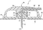
図1は、プラスチック基部10に取外し可能に取り付けられているプラスチック流体コネクタまたはハブ22と、流体チューブ類セット28と、ポンプ(図示せず)に取付け可能なプラスチックコネクタ26とを有する鋼製カニューレの注入セット1を示す。コネクタ26は外壁262を含む。ラインセット20は、ハブ22と流体チューブ類セット28とを含む。図2および図3に示されている通り、ラインセット20は、基部10に取り付けられているかまたはそれから取外し可能である。 FIG. 1 shows a steel cannula having a plastic fluid connector or
図2は、ハブ22が基部10に取り付けられている状態で示されている、注入セット1の上面図である。接着パッド19は、基部10に取り付けられており、使用者の皮膚に取付け可能であるように構成されている。図3は、注入セット1の図を示し、ラインセット20は基部10から取り外されている。基部10は、鋼製カニューレ13が取り付けられている注入アダプタ14を含む。 FIG. 2 is a top view of the
図4は、注入液(インスリン)がどのように鋼製カニューレ13内にポンプで送り込まれるかをより明確に示している、図1の線4−4に沿った、注入セット1の横断面図である。ラインセット20のハブ22は、流体チューブ類セット28を受容するハブポート25を含む。ハブ22は流動カニューレ24を含む。基部10は主基底部12を含み、アダプタ14は、鋼製カニューレ13が取り付けられている円筒形下部16と、下部16から離間されている円筒形内壁部17とを含む。図3および図5に示されている通り、ハブ22が注入基部10に取り付けられていない場合、プリスリット隔壁18がアダプタ14の上部を封入している。 FIG. 4 shows a cross-sectional view of the infusion set 1 along line 4-4 of FIG. 1, more clearly showing how the infusion solution (insulin) is pumped into the
ハブ22が基部10に取り付けられているとき、流動カニューレ24は、鋼製カニューレ13が経路11経由で流体チューブ類セット28と流体連通しているように、基部10のプリスリット隔壁18を貫通する。このことにより、ポンプ(図示せず)からのインスリンが流体チューブ類セット28から鋼製カニューレ13内に流動することが可能になり、インスリンは鋼製カニューレ13の遠位開口部また先端部131を出て、患者身体内に入る。 When the
図5は、基部10に取り付けられており鋼製カニューレ13を保護する円筒形保護装置30を示す。使用前に、基部10に形状が適合する保護装置30は除去され、通常はプラスチックで作製されている管状構造の保護装置30は廃棄される。 FIG. 5 shows a
鋼製カニューレの注入セットが配設される場合に問題が生じる。鋼製カニューレ13が使用者から除去される場合、それは最初の挿入後2〜3日である可能性があり、使用者は、現在は体液を含む可能性がある鋼製カニューレ13を覆う使い捨て保護装置30または保護チューブをもはや有していない可能性がある。使い捨て保護チューブ30が利用可能であったとしても、基部10への取付けはそれほどしっかりしていないので、保護チューブ30は基部10から容易に取り外され、使用済みの鋼製カニューレ13を露出する可能性があるであろう。 Problems arise when a steel cannula infusion set is deployed. If the
使用者は、注入セット1および注射器などの鋭利な針を含む物品の廃棄のために設計されている鋭利品容器(sharps container)内で鋼製カニューレの注入セット1を廃棄すると考えられる。しかし、使用者が使用済みの鋼製の注入セット1を廃棄し交換することを希望する場合、鋭利品容器が容易に入手可能でない可能性がある。 The user would discard the steel cannula infusion set 1 in a sharps container that is designed for the disposal of the
したがって、そのような接触から人々を保護するために、鋼製カニューレが露出しないように使用済みの鋼製針の注入セットを安全に廃棄することができる、改良された注入セットの設計および構成が必要とされている。 Therefore, there is an improved infusion set design and configuration that can safely discard the used steel needle infusion set so that the steel cannula is not exposed to protect people from such contact. is necessary.
本発明の目的は、保護要素をしっかり受容する注入基部を提供することである。本発明のある態様に従って、保護要素は、流体チューブ類セットのコネクタとすることができる。 It is an object of the present invention to provide an injection base that securely receives a protective element. In accordance with an aspect of the present invention, the protective element can be a connector of a fluid tubing set.
本発明の目的は、注入基部上に雄ねじおよび相互的な雌溝などの連結要素、ならびに係合および係合解除のために流体チューブ類セットのコネクタを提供することである。 It is an object of the present invention to provide connecting elements such as male threads and reciprocal female grooves on the injection base, and connectors for fluid tubing sets for engagement and disengagement.
本発明の別の目的は、コネクタを受容しかつそこからのコネクタの取外しに抵抗することができる、注入基部上の1つまたは複数の可撓性タブを提供することである。 Another object of the present invention is to provide one or more flexible tabs on the infusion base that can accept the connector and resist removal of the connector therefrom.
これらの目的および他の目的は、実質的に、注入基部の要素を修正して鋼製カニューレを望ましくない接触から保護することにより達成される。 These and other objectives are substantially achieved by modifying the elements of the injection base to protect the steel cannula from unwanted contact.
本発明の例示的実施形態の種々の目的、利点、および新規の特徴は、添付図面と併せ読めば、以下の詳細な説明からより容易に理解されるであろう。
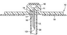
図6〜図8は、本発明による注入セットの一実施形態を示す。本実施形態では、注入セット1aは、基部10aに取付け可能なラインセット20を含む。ラインセット20は、ハブ22とハブ22に取り付けられている流体チューブ類セット28とを含む。流体チューブ類セット28の端部が、注入液貯蔵容器またはポンプ(図示せず)に取り付くことができる、Luer−Lok(登録商標)の商標で販売されている従来のISO594ねじ付きコネクタなどのコネクタ26aに連結されている。本発明に従って、基部10aは、その直径が上から下の方向に減少するテーパのまたは円錐台形の下部16aを有するアダプタ14と、ねじ付き円筒形内壁部17aとを含む。コネクタ26aを受容するのに十分な空間が、下部16aと内壁部17aとの間に形成されている。コネクタ26aは、その直径が上から下の方向に減少するテーパのまたは円錐台形の内壁260aと、円筒形外壁262aとを含む。下部16aと円錐台形内壁260aとのテーパ(公称6%)は、適合しているかまたは相補的である。ねじ263が、(例えば、Luer−Lok(登録商標)などの)コネクタ、コネクタ26aの外壁262a上に形成されている。コネクタ26aは基部10aに取り付くように構成されている。コネクタ26aの外壁262a上のねじ263は、図8に示されている通り、アダプタ14の円筒形内壁部17a上に形成されている対応するねじまたは溝171に回転可能に取り付けられて、コネクタ26aを基部10aに取外し可能に取り付けるように構成されている。 6-8 illustrate one embodiment of an infusion set according to the present invention. In the present embodiment, the infusion set 1a includes a line set 20 that can be attached to the
また、外ねじ263はLuer−Lok(登録商標)コネクタとしての機能を果たして、ポンプまたは貯蔵容器(図示せず)の対応する溝と直接接続し、使用者に注入液を投与する。図7は、ハブ22が取り外されている状態の基部10aを示す。アダプタ14の内壁17aは、コネクタ26aのねじ263を受容するねじまたは溝171を含む。 Also, the
図8は、コネクタ26aが基部10aに固定されている基部10aを示す。コネクタ26aは、基部10aに固定されるように回転可能に取り付けられている。ねじ263は、対応するねじまたは溝171内に回転可能に挿入されて、コネクタを基部10aにしっかりと取り付ける。コネクタ26aの回転を反転させることにより、コネクタ26aが基部10aから解除される。ハブ22が基部10aに固定される方法は、図1〜図5の実施形態に示されているものと類似している。コネクタ23が基部10aに取り付けられた場合、図8に示されている通り、カニューレ13は、アダプタ14の下部16aから延在しているカニューレ13の一部がコネクタ26aの円筒形内壁260aとの間に形成されている空間内に収容されている状態で、コネクタ23により保護され、その穿刺先端部131を含めてカニューレ13との接触を防止する。 FIG. 8 shows the
図6〜図8の実施形態の修正形態において、図9〜図11に示されている通り、注入セット1bでは、(図6〜図8の実施形態の)ねじまたは溝171およびねじ263は取り除かれている可能性があり、流体コネクタ26bと基部10bの下部16bとの間の取付けは、従来のISO594ルアー(Luer)式滑合に類似している、下部160bの嵌合テーパ面または円錐台形面と内壁260bとの間の摩擦締りに依存している。 In a modification of the embodiment of FIGS. 6-8, as shown in FIGS. 9-11, in the infusion set 1b, the screw or groove 171 and screw 263 (of the embodiment of FIGS. 6-8) are removed. The mounting between the
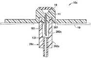
図12〜図14が、本発明の例示的注入セットの別の実施形態を示す。本実施形態では、注入セット1cが、基部10cに取付け可能なハブ22を含む。本実施形態では、アダプタ14の下部16cはねじ部分161を含み、コネクタ26cの内壁260cは、コネクタ26cが基部10cに回転可能に取り付けられた場合にねじ161を受容する、対応するねじまたは溝261を含む。ルアー式でない本実施形態では、下部16cおよび内壁260cは、円錐台形ではなく円筒形であってもよい。 12-14 illustrate another embodiment of an exemplary infusion set of the present invention. In the present embodiment, the infusion set 1c includes a
図13は、その外面上にねじ161を有する、アダプタ14の下部16cを示す、基部10cの横断面図である。内壁部16cとアダプタ14の内壁部17cとの間に空間があり、コネクタ26cを受容する。この空間内で、コネクタ26cを基部10cに固定することができる。図14は、コネクタ26cが固定されている状態の基部10cを示す。本実施形態では、アダプタの下部16cのねじ161は、コネクタ26cの内壁の対応する溝261に回転可能に取り付けられており、コネクタ26cを基部10cに取り付けている。したがって、鋼製カニューレ13は、鋼製カニューレ13の先端部131との望ましくないまたは偶発的な接触を防止して汚染を回避するために、望ましくない外的接触から安全に保護されている。 FIG. 13 is a cross-sectional view of the
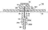
図15〜図17は、本発明の注入セットのさらに別の実施形態を示す。本実施形態では、注入セット1dが、ラインセット20が取り付けられている基部10dを含む。図15に示されている通り、コネクタ26dがその端部に取り付けられている状態で、ラインセット20はハブ22と流体チューブ類セット28とを含む。1つまたは複数の可撓性タブ50が、取り付けられているかまたは基部10dの下面と一体的に形成されている。コネクタ26dは、可撓性タブ50が変形して退くと環状リブ266が内壁部17dとアダプタ14dの下部16dとの間の空間内に嵌合することができるように、環状リブ266と円筒形のまたは円錐台形の内壁260dを含む。可撓性タブ50がその元の形状に戻ると、コネクタ26dにおける過剰な引っ張りがないときは、図17に示されている通り、可撓性タブ50は環状リブを保持することができる。内壁260dが円筒形である場合、下部16dもまた円筒形である。同様に、内壁260dが円錐台形である場合、下部16dもまた円錐台形であり、図17に示されている通り、内壁260dが下部16dに係合するとルアー式クサビ嵌合を可能にする。 15-17 illustrate yet another embodiment of the infusion set of the present invention. In this embodiment, the infusion set 1d includes a
図15Aは、図15の実施形態の変形形態を示す。本実施形態では、基部10d’は、基部10d’の下面に取り付けられているかまたはそれと一体的に形成されている1つまたは複数の実質的に剛性のタブ50’を含む。本実施形態のコネクタ26eは、コネクタ26dのタブ266’が基部10d’のタブ50’間の空間内にうまく嵌め込まれ、コネクタ26dが若干回転させられるとタブ266’およびタブ50’が摩擦係合されてコネクタ26dを基部10d’に結合し、カニューレ13のための保護遮蔽をもたらすことができるように、Luer−Lok(登録商標)ねじ区域などの1つまたは複数の剛性タブ266’を含む。 FIG. 15A shows a variation of the embodiment of FIG. In this embodiment,
図16は、図15の注入基部10dの横断面図であり、基部10dの主要基底部12の底面上に固定されている可撓性タブ50を示す。図17は、コネクタ26dの環状リブ266の外側リップ267が内壁部17dとアダプタ14の下部16dとの間の空間内に挿入された後にコネクタ26dが固定されている状態の、注入基部10dを示す。タブ50は、コネクタ26dの外側リップ267に対する抵抗をもたらして、図17に示されている通り、コネクタ26dをアダプタ10dに取外し可能に固定する。1つまたは複数の可撓性タブ50を下部16d上に形成して、コネクタ26dを基部10dに固定することができると考えられる。 FIG. 16 is a cross-sectional view of the
本発明の実施形態では、通常は注入セットと共に含まれている円筒形チューブの形の(図5に示されている)保護装置30は、完全に無くすことができる。図6〜図17のコネクタ26a、26b、26c、26dおよび26eは、注入セットが使用される前後にコネクタ26a、26b、26c、26dおよび26eを使用して鋼製カニューレを遮蔽することができ、それにより余分になる可能性がある部分を無くしかつ全体的な製造コストを低減することができるため、そのような保護装置30を不要にすることができる。プラスチック保護装置30の除去により、さもなければ再利用しなければならないかまたはごみ廃棄場に捨てなければならないであろうそのような保護装置30を廃棄する必要が無くなる。 In embodiments of the present invention, the protective device 30 (shown in FIG. 5), usually in the form of a cylindrical tube that is included with the infusion set, can be eliminated entirely. The
注入セットを使用するために、使用者が最初に基部10a、10b、10c、10d、10d’から各コネクタ26a、26b、26c、26dおよび26eを取り外して、注入治療のために使用者に取り付けるためにカニューレ13を露出させなければならないように、注入セット1a、1b、1c、1dおよび1d’は、基部10a、10b、10c、10dおよび10d’に連結されている各コネクタ26a、26b、26c、26dおよび26eと共に使用者に与えることができる。カニューレ13を備えた基部10a、10b、10c、10dおよび10d’が使用者の皮膚を穿刺した後、図1〜図5に関して前述されている通り注入治療が行われる。その後、使用者が使用者の皮膚から基部10a、10b、10c、10d、10d’を除去し、コネクタ26a、26b、26c、26d、26eがポンプまたは貯蔵容器(図示せず)から取り外された後、コネクタ26a、26b、26c、26d、26eは、カニューレ13を覆って再度固定されて、体液を含むカニューレ13を接触から保護することができる。 In order to use the infusion set, the user first removes each
したがって、多くの注入セットに見られる構成要素(保護装置30)を無くすことができ、カニューレ13を、既に注入セット1a、1b、1c、1dおよび1d’の一部である部分(コネクタ26a、26b、26c、26d)により覆うことができる。これにより、さもなければ露出されたカニューレと共に廃棄されるであろう使用済みの注入セットの適切な廃棄の問題が解決される。この方法では、注入セットのカニューレを、注入治療の前後に保護することができ、使用済みの注入セットをカニューレが固定されている状態で、安全に輸送するかまたは廃棄することができる。 Thus, the components found in many infusion sets (protection device 30) can be eliminated and the
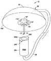
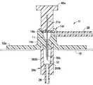
前述の実施形態は、剛性で通常はステンレス鋼で作製されているものであるカニューレ13を各々が含む注入セットに関する。しかし、本発明は、そのような種類の注入セットに限定されない。図18は、剛性カニューレの代わりに柔軟な(例えばテフロン(登録商標))カテーテル30aを利用して使用者に注入液を送達する注入セット1eの基部10eを示す。当技術分野で既知であるように、柔軟なカテーテルの注入セットでは、柔軟なカテーテル30aを使用者の皮膚内に取り付けるために、図18に示されている通り、柔軟なカテーテル30aを通して誘導針31が挿入され、針31および柔軟なカテーテル30aがどちらも使用者の皮膚を穿刺するように、使用者は、誘導針31が取り付けられている針ハブ40を使用者の皮膚の方へ押す。その後、針ハブ40は基部10eから除去されて、柔軟なカテーテル30aが使用者の皮膚内に留まっている間に使用者の皮膚から針31を除去する。本発明に従って、注入セットは、針31およびカテーテル30aがどちらも最初に暴露から保護されるように構成することができる。具体的には、図18の実施形態では、針ハブ40は、最初に、コネクタ26bが基部10eに取り付けられて柔軟なカテーテル30aおよび誘導針31の両方を保護している状態で基部10e上に配置される。コネクタ26bの基部10eへの取付け方法は、図6〜図17に記載されているカニューレ式注入セットに関して記載されているものと同じにすることができる。注入治療を可能にするために、針31および針ハブ40は除去され、図4に示されているのと同じ方法で、ラインセットハブ20が基部10e上に配置される。 The foregoing embodiments relate to an infusion set that each includes a
図19および図20は、その針31aが先端部32経由で使用者の皮膚を突き通した後に針ハブ40aが除去された場合に、注入液がチューブ類セット28から経路11内へかつカテーテル30bを通って外へ供給されるように注入治療を行うことができるように、流体チューブ類セット28が基部10fのアダプタ14aに永久に連結されている場合の、別の柔軟なカテーテルセットを示す。セルフシール隔壁18aは、針ハブ40aが注入セット10aから除去されると、針31aがカテーテル30bから隔壁18aを通って外へ除去された後に自動閉鎖する。 19 and 20 show that when the
図19および図20の実施形態では、針ハブ40aを、コネクタ26bがアダプタ14aに取り付けられている状態で基部10f上に配置して、柔軟なカテーテル30bと誘導針31aの両方を保護することができる。コネクタ26bの基部10fへの取付け方法は、図6〜図17に記載されているカニューレ式注入セットに関して記載されているものと同じにすることができる。 In the embodiment of FIGS. 19 and 20, the
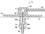
図21および図22の実施形態は、本実施形態が、柔軟なカテーテルの代わりに剛性のまたは鋼製のカニューレ13を備えた注入セット1gに関することを除いて、図19および図20の実施形態のものと類似している。剛性カニューレ13はそれだけで皮膚を突き通すことができるので、別個の誘導針が不要である。注入セット1gは、流体チューブ類セット28、経路11、およびカニューレ13が流体連通しており、注入治療を可能にするように、カニューレ13と、基部10gのアダプタ14bに取り付けられている流体チューブ類セット28とを含む。図6〜図17の実施形態と同様に、図20および図21の実施形態では、コネクタ26bの基部10gへの取付け方法は、図6〜図17に記載されているカニューレ式注入セットに関して記載されているものと同じにすることができる。 The embodiment of FIGS. 21 and 22 differs from the embodiment of FIGS. 19 and 20 except that this embodiment relates to an infusion set 1g with a rigid or
前段で本発明の限られた数の実施形態のみを詳細に記載したが、本発明の新規の教示および利点から著しく逸脱することなく、例示的実施形態において多数の修正形態が可能であることを、当業者は容易に理解するであろう。したがって、全てのそのような修正形態は、添付の特許請求の範囲およびそれらの等価物において定められる本発明の範囲の範囲内に含まれるものとする。 Although only a limited number of embodiments of the present invention have been described in detail above, it should be understood that numerous modifications are possible in the exemplary embodiments without significantly departing from the novel teachings and advantages of the present invention. Those skilled in the art will readily understand. Accordingly, all such modifications are intended to be included within the scope of this invention as defined in the appended claims and their equivalents.
Claims (21)
Translated fromJapanese前記注入基部から延在している注入カニューレであって、前記使用者の皮膚を穿刺するために開いた端部に穿刺部を含む、注入カニューレと、
前記注入基部に連結可能なハブと、
前記ハブに取り付けられている一端および開いた端部を含むチューブセットであって、前記チューブセットの前記開いた端部は、注入液を供給する注入ポンプに取付け可能であり、また前記注入基部に取付け可能であり、注入液が供給されていないとき前記注入カニューレの前記穿刺部を保護するコネクタを含む、チューブセットと
を含み、
可撓性タブが前記アダプタの前記間隙の外周上に配置されており、前記コネクタは、前記アダプタの前記間隙内にうまく嵌め込まれるように構成されている環状リブを含み、前記可撓性タブは、前記環状リブが前記アダプタの前記間隙内に挿入されるかまたはそこから除去されるとき、前記環状リブに対して抵抗をもたらすことを特徴とする注入セット。An injection base for attachment to a user, comprising a lower part, an inner wall part, and an adapter having a gap between the lower part and the inner wall part; and
An infusion cannula extending from the infusion base, the infusion cannula including a puncture at an open end to puncture the user's skin;
A hub connectable to the injection base;
A tube set including an end attached to the hub and an open end, the open end of the tube set being attachable to an infusion pump for supplying an infusate and to the infusion base A tube set including a connector that is attachable and that protects the puncture portion of the infusion cannula when infusion is not being supplied;
A flexible tab is disposed on the outer periphery of the gap of the adapter, and the connector includes an annular rib configured to fit well within the gap of the adapter, the flexible tab being An infusion set that provides resistance to the annular rib when the annular rib is inserted into or removed from the gap of the adapter.
下部および内壁部、ならびに前記下部と前記内壁部との間に間隙を含むアダプタであって、前記下部および前記内壁部の少なくとも1つが付属品を受容するように構成されている、アダプタと、
前記アダプタの前記間隙の外周上に配置されている可撓性タブと
を含み、
前記可撓性タブは、流体チューブ類セットをポンプに取り付けるためのコネクタの環状リブであって前記アダプタの前記間隙内にうまく嵌め込まれるように構成されている環状リブが前記アダプタの前記間隙内に挿入されるかまたはそこから除去されるとき、前記環状リブに対して抵抗をもたらすことを特徴とする注入基部。An injection base for attachment to a user of an infusion set,
An adapter including a lower portion and an inner wall portion and a gap between the lower portion and the inner wall portion, wherein at least one of the lower portion and the inner wall portion is configured to receive an accessory;
A flexible tab disposed on the outer periphery of the gap of the adapter;
The flexible tab is an annular rib of a connector for attaching a set of fluid tubing to the pump, and the annular rib is configured to fit well within the gap of the adapter. Injection base characterized in that it provides resistance to said annular rib when inserted or removed therefrom.
針またはカニューレと、
流体コネクタを前記基部に取り付けて前記針または前記カニューレを覆う、前記基部上の手段と
を含み、
可撓性タブが前記アダプタの前記間隙の外周上に配置されており、前記流体コネクタは、前記アダプタの前記間隙内にうまく嵌め込まれるように構成されている環状リブを含み、前記可撓性タブは、前記環状リブが前記アダプタの前記間隙内に挿入されるかまたはそこから除去されるとき、前記環状リブに対して抵抗をもたらすことを特徴とする注入セット。A base including a lower portion, an inner wall portion, and an adapter having a gap between the lower portion and the inner wall portion;
With a needle or cannula,
Means on the base for attaching a fluid connector to the base and covering the needle or the cannula;
A flexible tab is disposed on an outer periphery of the gap of the adapter, and the fluid connector includes an annular rib configured to fit well within the gap of the adapter; The infusion set is characterized in that it provides resistance to the annular rib when the annular rib is inserted into or removed from the gap of the adapter.
カテーテルと、
流体コネクタを前記基部に取り付けて前記カテーテルを覆う、前記基部上の手段と
を含み、
可撓性タブが前記アダプタの前記間隙の外周上に配置されており、前記流体コネクタは、前記アダプタの前記間隙内にうまく嵌め込まれるように構成されている環状リブを含み、前記可撓性タブは、前記環状リブが前記アダプタの前記間隙内に挿入されるかまたはそこから除去されるとき、前記環状リブに対して抵抗をもたらすことを特徴とする注入セット。A base including a lower portion, an inner wall portion, and an adapter having a gap between the lower portion and the inner wall portion;
A catheter;
Means on the base for attaching a fluid connector to the base and covering the catheter;
A flexible tab is disposed on an outer periphery of the gap of the adapter, and the fluid connector includes an annular rib configured to fit well within the gap of the adapter; The infusion set is characterized in that it provides resistance to the annular rib when the annular rib is inserted into or removed from the gap of the adapter.
Applications Claiming Priority (2)
| Application Number | Priority Date | Filing Date | Title |
|---|---|---|---|
| US13/646,582 | 2012-10-05 | ||
| US13/646,582US9789250B2 (en) | 2012-10-05 | 2012-10-05 | Infusion set with safety device |
Related Parent Applications (1)
| Application Number | Title | Priority Date | Filing Date |
|---|---|---|---|
| JP2013210304ADivisionJP6621974B2 (en) | 2012-10-05 | 2013-10-07 | Infusion set with safety device |
Publications (2)
| Publication Number | Publication Date |
|---|---|
| JP2018126587Atrue JP2018126587A (en) | 2018-08-16 |
| JP6560395B2 JP6560395B2 (en) | 2019-08-14 |
Family
ID=49378055
Family Applications (2)
| Application Number | Title | Priority Date | Filing Date |
|---|---|---|---|
| JP2013210304AActiveJP6621974B2 (en) | 2012-10-05 | 2013-10-07 | Infusion set with safety device |
| JP2018083352AActiveJP6560395B2 (en) | 2012-10-05 | 2018-04-24 | Infusion set with safety device |
Family Applications Before (1)
| Application Number | Title | Priority Date | Filing Date |
|---|---|---|---|
| JP2013210304AActiveJP6621974B2 (en) | 2012-10-05 | 2013-10-07 | Infusion set with safety device |
Country Status (6)
| Country | Link |
|---|---|
| US (3) | US9789250B2 (en) |
| EP (1) | EP2716314B1 (en) |
| JP (2) | JP6621974B2 (en) |
| CN (1) | CN203874209U (en) |
| CA (3) | CA2828832C (en) |
| ES (1) | ES2727902T3 (en) |
Families Citing this family (21)
| Publication number | Priority date | Publication date | Assignee | Title |
|---|---|---|---|---|
| CA2858199C (en) | 2011-12-07 | 2020-05-12 | Becton, Dickinson And Company | Infusion device with releasable fluid connector |
| ES2666386T3 (en) | 2011-12-07 | 2018-05-04 | Becton, Dickinson And Company | Needle protection sets and infusion devices for use with them |
| US9789250B2 (en) | 2012-10-05 | 2017-10-17 | Becton, Dickinson And Company | Infusion set with safety device |
| USD747456S1 (en)* | 2012-12-07 | 2016-01-12 | Becton, Dickinson And Company | Infusion set assembly |
| USD756504S1 (en)* | 2012-12-07 | 2016-05-17 | Becton, Dickinson And Company | Infusion set base |
| USD747459S1 (en)* | 2012-12-07 | 2016-01-12 | Becton, Dickinson And Company | Infusion set assembly |
| USD754843S1 (en)* | 2012-12-07 | 2016-04-26 | Becton, Dickinson And Company | Infusion set assembly |
| USD754842S1 (en)* | 2012-12-07 | 2016-04-26 | Becton, Dickinson And Company | Infusion set needle guard |
| USD747457S1 (en)* | 2012-12-07 | 2016-01-12 | Becton, Dickinson And Company | Infusion set needle guard |
| USD747458S1 (en)* | 2012-12-07 | 2016-01-12 | Becton, Dickinson And Company | Infusion set insertion needle assembly |
| CN106470717B (en) | 2014-06-03 | 2020-09-11 | 安姆根有限公司 | Drug delivery system and method of use |
| JP6716566B2 (en) | 2014-12-19 | 2020-07-01 | アムジエン・インコーポレーテツド | Drug delivery device with proximity sensor |
| US11357916B2 (en) | 2014-12-19 | 2022-06-14 | Amgen Inc. | Drug delivery device with live button or user interface field |
| US10576207B2 (en) | 2015-10-09 | 2020-03-03 | West Pharma. Services IL, Ltd. | Angled syringe patch injector |
| US11318254B2 (en) | 2015-10-09 | 2022-05-03 | West Pharma. Services IL, Ltd. | Injector needle cap remover |
| JP6885960B2 (en) | 2016-01-21 | 2021-06-16 | ウェスト ファーマ サービシーズ イスラエル リミテッド | Drug delivery device with visual indicators |
| US10646643B2 (en)* | 2016-01-21 | 2020-05-12 | West Pharma. Services IL, Ltd. | Needle insertion and retraction mechanism |
| USD1013864S1 (en) | 2021-08-26 | 2024-02-06 | Deka Products Limited Partnership | Fluid administration apparatus assembly |
| USD1057941S1 (en) | 2022-08-26 | 2025-01-14 | Deka Products Limited Partnership | Patient care assembly component |
| USD1090862S1 (en) | 2022-08-26 | 2025-08-26 | Deka Products Limited Partnership | Adhering assembly for medical devices and the like |
| USD1043976S1 (en) | 2022-08-26 | 2024-09-24 | Deka Products Limited Partnership | Fluid transfer connector |
Citations (7)
| Publication number | Priority date | Publication date | Assignee | Title |
|---|---|---|---|---|
| US3670727A (en)* | 1970-04-16 | 1972-06-20 | American Hospital Supply Corp | Medical infusion set |
| JP2000342686A (en)* | 1999-06-01 | 2000-12-12 | Terumo Corp | Needle for medical purpose, and medical apparatus |
| JP2003024455A (en)* | 2001-07-06 | 2003-01-28 | Soo Bong Choi | Injection needle unit for insulin automatic injector |
| JP2005518907A (en)* | 2002-03-08 | 2005-06-30 | オプティ、フランス、ソシエテ、アノニム | Medical connector assembly for fluid transfer |
| JP2007511325A (en)* | 2003-11-18 | 2007-05-10 | アイシーユー メディカル インコーポレイテッド | Infusion set |
| US20070185441A1 (en)* | 2006-02-07 | 2007-08-09 | Fangrow Thomas F Jr | Infusion set |
| JP2012115673A (en)* | 2010-11-30 | 2012-06-21 | Becton Dickinson & Co | Adjustable height needle infusion device |
Family Cites Families (14)
| Publication number | Priority date | Publication date | Assignee | Title |
|---|---|---|---|---|
| US2452643A (en)* | 1946-05-23 | 1948-11-02 | Abbott Lab | Disposable venoclysis set |
| US2737951A (en)* | 1952-12-11 | 1956-03-13 | Bronwill Scient Inc | Clinical cannula or tubule device |
| FR1209337A (en) | 1958-07-30 | 1960-03-01 | Improvement of large volume blood transfusion and solution infusion devices | |
| JPS5280585U (en)* | 1975-12-05 | 1977-06-16 | ||
| JPS5280585A (en)* | 1975-12-26 | 1977-07-06 | Fanuc Ltd | Turret device |
| US5545143A (en) | 1993-01-21 | 1996-08-13 | T. S. I. Medical | Device for subcutaneous medication delivery |
| US5322515A (en)* | 1993-03-15 | 1994-06-21 | Abbott Laboratories | Luer adapter assembly for emergency syringe |
| US6106502A (en)* | 1996-12-18 | 2000-08-22 | Richmond; Frank M. | IV sets with needleless fittings and valves |
| US7338465B2 (en) | 2002-07-02 | 2008-03-04 | Patton Medical Devices, Lp | Infusion device and method thereof |
| US7494481B2 (en) | 2004-12-03 | 2009-02-24 | Medtronic Minimed, Inc. | Multi-position infusion set device and process |
| US7520867B2 (en) | 2003-11-10 | 2009-04-21 | Medtronic Minimed, Inc. | Subcutaneous infusion set |
| US20080249505A1 (en)* | 2007-03-30 | 2008-10-09 | Animas Corporation | Method for mounting an infusion set with user-controlled 360-degree rotary motion hub to an infusion site |
| US7967797B2 (en)* | 2009-05-19 | 2011-06-28 | Nexus Medical, Llc | Intravascular valve component with improved valve positioning |
| US9789250B2 (en)* | 2012-10-05 | 2017-10-17 | Becton, Dickinson And Company | Infusion set with safety device |
- 2012
- 2012-10-05USUS13/646,582patent/US9789250B2/enactiveActive
- 2013
- 2013-10-01CACA2828832Apatent/CA2828832C/enactiveActive
- 2013-10-01CACA3198239Apatent/CA3198239A1/enactivePending
- 2013-10-01CACA3111543Apatent/CA3111543C/enactiveActive
- 2013-10-02ESES13187145Tpatent/ES2727902T3/enactiveActive
- 2013-10-02EPEP13187145.1Apatent/EP2716314B1/enactiveActive
- 2013-10-07JPJP2013210304Apatent/JP6621974B2/enactiveActive
- 2013-10-08CNCN201320897244.5Upatent/CN203874209U/ennot_activeExpired - Lifetime
- 2017
- 2017-09-19USUS15/708,710patent/US10821226B2/enactiveActive
- 2018
- 2018-04-24JPJP2018083352Apatent/JP6560395B2/enactiveActive
- 2020
- 2020-09-28USUS17/035,561patent/US11541172B2/enactiveActive
Patent Citations (7)
| Publication number | Priority date | Publication date | Assignee | Title |
|---|---|---|---|---|
| US3670727A (en)* | 1970-04-16 | 1972-06-20 | American Hospital Supply Corp | Medical infusion set |
| JP2000342686A (en)* | 1999-06-01 | 2000-12-12 | Terumo Corp | Needle for medical purpose, and medical apparatus |
| JP2003024455A (en)* | 2001-07-06 | 2003-01-28 | Soo Bong Choi | Injection needle unit for insulin automatic injector |
| JP2005518907A (en)* | 2002-03-08 | 2005-06-30 | オプティ、フランス、ソシエテ、アノニム | Medical connector assembly for fluid transfer |
| JP2007511325A (en)* | 2003-11-18 | 2007-05-10 | アイシーユー メディカル インコーポレイテッド | Infusion set |
| US20070185441A1 (en)* | 2006-02-07 | 2007-08-09 | Fangrow Thomas F Jr | Infusion set |
| JP2012115673A (en)* | 2010-11-30 | 2012-06-21 | Becton Dickinson & Co | Adjustable height needle infusion device |
Also Published As
| Publication number | Publication date |
|---|---|
| JP6621974B2 (en) | 2019-12-18 |
| CA2828832A1 (en) | 2014-04-05 |
| US20140100544A1 (en) | 2014-04-10 |
| JP6560395B2 (en) | 2019-08-14 |
| CA3111543C (en) | 2023-06-27 |
| EP2716314A1 (en) | 2014-04-09 |
| US10821226B2 (en) | 2020-11-03 |
| US20210008278A1 (en) | 2021-01-14 |
| CN203874209U (en) | 2014-10-15 |
| US11541172B2 (en) | 2023-01-03 |
| CA2828832C (en) | 2021-04-27 |
| US20180001020A1 (en) | 2018-01-04 |
| ES2727902T3 (en) | 2019-10-21 |
| CA3198239A1 (en) | 2014-04-05 |
| JP2014076362A (en) | 2014-05-01 |
| CA3111543A1 (en) | 2014-04-05 |
| US9789250B2 (en) | 2017-10-17 |
| EP2716314B1 (en) | 2019-03-06 |
Similar Documents
| Publication | Publication Date | Title |
|---|---|---|
| JP6560395B2 (en) | Infusion set with safety device | |
| CN101500627B (en) | Cannula and delivery device | |
| EP2155299B1 (en) | Delivery device | |
| CA2827953C (en) | Angled inserter for drug infusion | |
| EP2673021B1 (en) | Folding inserter for drug delivery infusion set | |
| US20040143216A1 (en) | Adapter connector for an infusion set and inserter system | |
| US9375552B2 (en) | Safety needle assembly | |
| JP2005515798A (en) | Fluid pump infusion set | |
| EP3204066B1 (en) | Needle cover assembly | |
| US20080177234A1 (en) | Safety subcutaneous infusion set | |
| KR20210013093A (en) | Syringe needle insertion and retraction assembly | |
| US20190381234A1 (en) | Arteriovenous access catheter with protectable inline needle | |
| US11547795B2 (en) | Needle hub for subcutaneous infusion set | |
| KR101228585B1 (en) | A syringe | |
| US10286187B2 (en) | Safe catheter | |
| JP6511863B2 (en) | Indwelling needle assembly |
Legal Events
| Date | Code | Title | Description |
|---|---|---|---|
| A621 | Written request for application examination | Free format text:JAPANESE INTERMEDIATE CODE: A621 Effective date:20180522 | |
| A977 | Report on retrieval | Free format text:JAPANESE INTERMEDIATE CODE: A971007 Effective date:20190313 | |
| A131 | Notification of reasons for refusal | Free format text:JAPANESE INTERMEDIATE CODE: A131 Effective date:20190319 | |
| A521 | Request for written amendment filed | Free format text:JAPANESE INTERMEDIATE CODE: A523 Effective date:20190606 | |
| TRDD | Decision of grant or rejection written | ||
| A01 | Written decision to grant a patent or to grant a registration (utility model) | Free format text:JAPANESE INTERMEDIATE CODE: A01 Effective date:20190618 | |
| A61 | First payment of annual fees (during grant procedure) | Free format text:JAPANESE INTERMEDIATE CODE: A61 Effective date:20190718 | |
| R150 | Certificate of patent or registration of utility model | Ref document number:6560395 Country of ref document:JP Free format text:JAPANESE INTERMEDIATE CODE: R150 | |
| R250 | Receipt of annual fees | Free format text:JAPANESE INTERMEDIATE CODE: R250 | |
| R250 | Receipt of annual fees | Free format text:JAPANESE INTERMEDIATE CODE: R250 | |
| R250 | Receipt of annual fees | Free format text:JAPANESE INTERMEDIATE CODE: R250 |