JP2018122098A - Footwear having sensor system - Google Patents
Footwear having sensor systemDownload PDFInfo
- Publication number
- JP2018122098A JP2018122098AJP2018020022AJP2018020022AJP2018122098AJP 2018122098 AJP2018122098 AJP 2018122098AJP 2018020022 AJP2018020022 AJP 2018020022AJP 2018020022 AJP2018020022 AJP 2018020022AJP 2018122098 AJP2018122098 AJP 2018122098A
- Authority
- JP
- Japan
- Prior art keywords
- sensor
- electronic module
- data
- footwear
- port
- Prior art date
- Legal status (The legal status is an assumption and is not a legal conclusion. Google has not performed a legal analysis and makes no representation as to the accuracy of the status listed.)
- Granted
Links
Images


Classifications
- A—HUMAN NECESSITIES
- A43—FOOTWEAR
- A43B—CHARACTERISTIC FEATURES OF FOOTWEAR; PARTS OF FOOTWEAR
- A43B17/00—Insoles for insertion, e.g. footbeds or inlays, for attachment to the shoe after the upper has been joined
- A43B17/003—Insoles for insertion, e.g. footbeds or inlays, for attachment to the shoe after the upper has been joined characterised by the material
- A43B17/006—Insoles for insertion, e.g. footbeds or inlays, for attachment to the shoe after the upper has been joined characterised by the material multilayered
- A—HUMAN NECESSITIES
- A43—FOOTWEAR
- A43B—CHARACTERISTIC FEATURES OF FOOTWEAR; PARTS OF FOOTWEAR
- A43B17/00—Insoles for insertion, e.g. footbeds or inlays, for attachment to the shoe after the upper has been joined
- A43B17/02—Insoles for insertion, e.g. footbeds or inlays, for attachment to the shoe after the upper has been joined wedge-like or resilient
- A—HUMAN NECESSITIES
- A43—FOOTWEAR
- A43B—CHARACTERISTIC FEATURES OF FOOTWEAR; PARTS OF FOOTWEAR
- A43B3/00—Footwear characterised by the shape or the use
- A—HUMAN NECESSITIES
- A43—FOOTWEAR
- A43B—CHARACTERISTIC FEATURES OF FOOTWEAR; PARTS OF FOOTWEAR
- A43B3/00—Footwear characterised by the shape or the use
- A43B3/34—Footwear characterised by the shape or the use with electrical or electronic arrangements
- A—HUMAN NECESSITIES
- A43—FOOTWEAR
- A43B—CHARACTERISTIC FEATURES OF FOOTWEAR; PARTS OF FOOTWEAR
- A43B3/00—Footwear characterised by the shape or the use
- A43B3/34—Footwear characterised by the shape or the use with electrical or electronic arrangements
- A43B3/44—Footwear characterised by the shape or the use with electrical or electronic arrangements with sensors, e.g. for detecting contact or position
- A—HUMAN NECESSITIES
- A43—FOOTWEAR
- A43B—CHARACTERISTIC FEATURES OF FOOTWEAR; PARTS OF FOOTWEAR
- A43B3/00—Footwear characterised by the shape or the use
- A43B3/34—Footwear characterised by the shape or the use with electrical or electronic arrangements
- A43B3/48—Footwear characterised by the shape or the use with electrical or electronic arrangements with transmitting devices, e.g. GSM or Wi-Fi®
- A—HUMAN NECESSITIES
- A61—MEDICAL OR VETERINARY SCIENCE; HYGIENE
- A61B—DIAGNOSIS; SURGERY; IDENTIFICATION
- A61B5/00—Measuring for diagnostic purposes; Identification of persons
- A61B5/103—Measuring devices for testing the shape, pattern, colour, size or movement of the body or parts thereof, for diagnostic purposes
- A61B5/1036—Measuring load distribution, e.g. podologic studies
- A61B5/1038—Measuring plantar pressure during gait
- A—HUMAN NECESSITIES
- A61—MEDICAL OR VETERINARY SCIENCE; HYGIENE
- A61B—DIAGNOSIS; SURGERY; IDENTIFICATION
- A61B5/00—Measuring for diagnostic purposes; Identification of persons
- A61B5/48—Other medical applications
- A61B5/486—Biofeedback
- A—HUMAN NECESSITIES
- A61—MEDICAL OR VETERINARY SCIENCE; HYGIENE
- A61B—DIAGNOSIS; SURGERY; IDENTIFICATION
- A61B5/00—Measuring for diagnostic purposes; Identification of persons
- A61B5/68—Arrangements of detecting, measuring or recording means, e.g. sensors, in relation to patient
- A61B5/6801—Arrangements of detecting, measuring or recording means, e.g. sensors, in relation to patient specially adapted to be attached to or worn on the body surface
- A61B5/6802—Sensor mounted on worn items
- A61B5/6804—Garments; Clothes
- A61B5/6807—Footwear
- A—HUMAN NECESSITIES
- A61—MEDICAL OR VETERINARY SCIENCE; HYGIENE
- A61B—DIAGNOSIS; SURGERY; IDENTIFICATION
- A61B5/00—Measuring for diagnostic purposes; Identification of persons
- A61B5/74—Details of notification to user or communication with user or patient; User input means
- A61B5/742—Details of notification to user or communication with user or patient; User input means using visual displays
- A—HUMAN NECESSITIES
- A63—SPORTS; GAMES; AMUSEMENTS
- A63B—APPARATUS FOR PHYSICAL TRAINING, GYMNASTICS, SWIMMING, CLIMBING, OR FENCING; BALL GAMES; TRAINING EQUIPMENT
- A63B24/00—Electric or electronic controls for exercising apparatus of preceding groups; Controlling or monitoring of exercises, sportive games, training or athletic performances
- A63B24/0062—Monitoring athletic performances, e.g. for determining the work of a user on an exercise apparatus, the completed jogging or cycling distance
- A—HUMAN NECESSITIES
- A63—SPORTS; GAMES; AMUSEMENTS
- A63B—APPARATUS FOR PHYSICAL TRAINING, GYMNASTICS, SWIMMING, CLIMBING, OR FENCING; BALL GAMES; TRAINING EQUIPMENT
- A63B69/00—Training appliances or apparatus for special sports
- A—HUMAN NECESSITIES
- A63—SPORTS; GAMES; AMUSEMENTS
- A63B—APPARATUS FOR PHYSICAL TRAINING, GYMNASTICS, SWIMMING, CLIMBING, OR FENCING; BALL GAMES; TRAINING EQUIPMENT
- A63B69/00—Training appliances or apparatus for special sports
- A63B69/0028—Training appliances or apparatus for special sports for running, jogging or speed-walking
- G—PHYSICS
- G06—COMPUTING OR CALCULATING; COUNTING
- G06F—ELECTRIC DIGITAL DATA PROCESSING
- G06F3/00—Input arrangements for transferring data to be processed into a form capable of being handled by the computer; Output arrangements for transferring data from processing unit to output unit, e.g. interface arrangements
- G06F3/01—Input arrangements or combined input and output arrangements for interaction between user and computer
- G06F3/03—Arrangements for converting the position or the displacement of a member into a coded form
- G06F3/033—Pointing devices displaced or positioned by the user, e.g. mice, trackballs, pens or joysticks; Accessories therefor
- G06F3/0334—Foot operated pointing devices
- A—HUMAN NECESSITIES
- A61—MEDICAL OR VETERINARY SCIENCE; HYGIENE
- A61B—DIAGNOSIS; SURGERY; IDENTIFICATION
- A61B90/00—Instruments, implements or accessories specially adapted for surgery or diagnosis and not covered by any of the groups A61B1/00 - A61B50/00, e.g. for luxation treatment or for protecting wound edges
- A61B90/06—Measuring instruments not otherwise provided for
- A61B2090/064—Measuring instruments not otherwise provided for for measuring force, pressure or mechanical tension
- A—HUMAN NECESSITIES
- A61—MEDICAL OR VETERINARY SCIENCE; HYGIENE
- A61B—DIAGNOSIS; SURGERY; IDENTIFICATION
- A61B2560/00—Constructional details of operational features of apparatus; Accessories for medical measuring apparatus
- A61B2560/04—Constructional details of apparatus
- A61B2560/0475—Special features of memory means, e.g. removable memory cards
- A—HUMAN NECESSITIES
- A63—SPORTS; GAMES; AMUSEMENTS
- A63B—APPARATUS FOR PHYSICAL TRAINING, GYMNASTICS, SWIMMING, CLIMBING, OR FENCING; BALL GAMES; TRAINING EQUIPMENT
- A63B69/00—Training appliances or apparatus for special sports
- A63B69/0002—Training appliances or apparatus for special sports for baseball
- A63B2069/0004—Training appliances or apparatus for special sports for baseball specially adapted for particular training aspects
- A63B2069/0006—Training appliances or apparatus for special sports for baseball specially adapted for particular training aspects for pitching
- A—HUMAN NECESSITIES
- A63—SPORTS; GAMES; AMUSEMENTS
- A63B—APPARATUS FOR PHYSICAL TRAINING, GYMNASTICS, SWIMMING, CLIMBING, OR FENCING; BALL GAMES; TRAINING EQUIPMENT
- A63B71/00—Games or sports accessories not covered in groups A63B1/00 - A63B69/00
- A63B71/06—Indicating or scoring devices for games or players, or for other sports activities
- A63B71/0619—Displays, user interfaces and indicating devices, specially adapted for sport equipment, e.g. display mounted on treadmills
- A63B71/0622—Visual, audio or audio-visual systems for entertaining, instructing or motivating the user
- A63B2071/0638—Displaying moving images of recorded environment, e.g. virtual environment
- A—HUMAN NECESSITIES
- A63—SPORTS; GAMES; AMUSEMENTS
- A63B—APPARATUS FOR PHYSICAL TRAINING, GYMNASTICS, SWIMMING, CLIMBING, OR FENCING; BALL GAMES; TRAINING EQUIPMENT
- A63B2102/00—Application of clubs, bats, rackets or the like to the sporting activity ; particular sports involving the use of balls and clubs, bats, rackets, or the like
- A63B2102/02—Tennis
- A—HUMAN NECESSITIES
- A63—SPORTS; GAMES; AMUSEMENTS
- A63B—APPARATUS FOR PHYSICAL TRAINING, GYMNASTICS, SWIMMING, CLIMBING, OR FENCING; BALL GAMES; TRAINING EQUIPMENT
- A63B2102/00—Application of clubs, bats, rackets or the like to the sporting activity ; particular sports involving the use of balls and clubs, bats, rackets, or the like
- A63B2102/18—Baseball, rounders or similar games
- A63B2102/182—Softball
- A—HUMAN NECESSITIES
- A63—SPORTS; GAMES; AMUSEMENTS
- A63B—APPARATUS FOR PHYSICAL TRAINING, GYMNASTICS, SWIMMING, CLIMBING, OR FENCING; BALL GAMES; TRAINING EQUIPMENT
- A63B2102/00—Application of clubs, bats, rackets or the like to the sporting activity ; particular sports involving the use of balls and clubs, bats, rackets, or the like
- A63B2102/22—Field hockey
- A—HUMAN NECESSITIES
- A63—SPORTS; GAMES; AMUSEMENTS
- A63B—APPARATUS FOR PHYSICAL TRAINING, GYMNASTICS, SWIMMING, CLIMBING, OR FENCING; BALL GAMES; TRAINING EQUIPMENT
- A63B2102/00—Application of clubs, bats, rackets or the like to the sporting activity ; particular sports involving the use of balls and clubs, bats, rackets, or the like
- A63B2102/32—Golf
- A—HUMAN NECESSITIES
- A63—SPORTS; GAMES; AMUSEMENTS
- A63B—APPARATUS FOR PHYSICAL TRAINING, GYMNASTICS, SWIMMING, CLIMBING, OR FENCING; BALL GAMES; TRAINING EQUIPMENT
- A63B2220/00—Measuring of physical parameters relating to sporting activity
- A63B2220/10—Positions
- A63B2220/12—Absolute positions, e.g. by using GPS
- A—HUMAN NECESSITIES
- A63—SPORTS; GAMES; AMUSEMENTS
- A63B—APPARATUS FOR PHYSICAL TRAINING, GYMNASTICS, SWIMMING, CLIMBING, OR FENCING; BALL GAMES; TRAINING EQUIPMENT
- A63B2220/00—Measuring of physical parameters relating to sporting activity
- A63B2220/40—Acceleration
- A—HUMAN NECESSITIES
- A63—SPORTS; GAMES; AMUSEMENTS
- A63B—APPARATUS FOR PHYSICAL TRAINING, GYMNASTICS, SWIMMING, CLIMBING, OR FENCING; BALL GAMES; TRAINING EQUIPMENT
- A63B2220/00—Measuring of physical parameters relating to sporting activity
- A63B2220/50—Force related parameters
- A63B2220/51—Force
- A63B2220/53—Force of an impact, e.g. blow or punch
- A—HUMAN NECESSITIES
- A63—SPORTS; GAMES; AMUSEMENTS
- A63B—APPARATUS FOR PHYSICAL TRAINING, GYMNASTICS, SWIMMING, CLIMBING, OR FENCING; BALL GAMES; TRAINING EQUIPMENT
- A63B2220/00—Measuring of physical parameters relating to sporting activity
- A63B2220/80—Special sensors, transducers or devices therefor
- A63B2220/83—Special sensors, transducers or devices therefor characterised by the position of the sensor
- A63B2220/836—Sensors arranged on the body of the user
- A—HUMAN NECESSITIES
- A63—SPORTS; GAMES; AMUSEMENTS
- A63B—APPARATUS FOR PHYSICAL TRAINING, GYMNASTICS, SWIMMING, CLIMBING, OR FENCING; BALL GAMES; TRAINING EQUIPMENT
- A63B2225/00—Miscellaneous features of sport apparatus, devices or equipment
- A63B2225/50—Wireless data transmission, e.g. by radio transmitters or telemetry
- A—HUMAN NECESSITIES
- A63—SPORTS; GAMES; AMUSEMENTS
- A63B—APPARATUS FOR PHYSICAL TRAINING, GYMNASTICS, SWIMMING, CLIMBING, OR FENCING; BALL GAMES; TRAINING EQUIPMENT
- A63B2243/00—Specific ball sports not provided for in A63B2102/00 - A63B2102/38
- A63B2243/0025—Football
- A—HUMAN NECESSITIES
- A63—SPORTS; GAMES; AMUSEMENTS
- A63B—APPARATUS FOR PHYSICAL TRAINING, GYMNASTICS, SWIMMING, CLIMBING, OR FENCING; BALL GAMES; TRAINING EQUIPMENT
- A63B2243/00—Specific ball sports not provided for in A63B2102/00 - A63B2102/38
- A63B2243/0066—Rugby; American football
- A—HUMAN NECESSITIES
- A63—SPORTS; GAMES; AMUSEMENTS
- A63B—APPARATUS FOR PHYSICAL TRAINING, GYMNASTICS, SWIMMING, CLIMBING, OR FENCING; BALL GAMES; TRAINING EQUIPMENT
- A63B26/00—Exercising apparatus not covered by groups A63B1/00 - A63B25/00
- A63B26/003—Exercising apparatus not covered by groups A63B1/00 - A63B25/00 for improving balance or equilibrium
- A—HUMAN NECESSITIES
- A63—SPORTS; GAMES; AMUSEMENTS
- A63F—CARD, BOARD, OR ROULETTE GAMES; INDOOR GAMES USING SMALL MOVING PLAYING BODIES; VIDEO GAMES; GAMES NOT OTHERWISE PROVIDED FOR
- A63F2300/00—Features of games using an electronically generated display having two or more dimensions, e.g. on a television screen, showing representations related to the game
- A63F2300/10—Features of games using an electronically generated display having two or more dimensions, e.g. on a television screen, showing representations related to the game characterized by input arrangements for converting player-generated signals into game device control signals
- A63F2300/1012—Features of games using an electronically generated display having two or more dimensions, e.g. on a television screen, showing representations related to the game characterized by input arrangements for converting player-generated signals into game device control signals involving biosensors worn by the player, e.g. for measuring heart beat, limb activity
- A—HUMAN NECESSITIES
- A63—SPORTS; GAMES; AMUSEMENTS
- A63F—CARD, BOARD, OR ROULETTE GAMES; INDOOR GAMES USING SMALL MOVING PLAYING BODIES; VIDEO GAMES; GAMES NOT OTHERWISE PROVIDED FOR
- A63F2300/00—Features of games using an electronically generated display having two or more dimensions, e.g. on a television screen, showing representations related to the game
- A63F2300/10—Features of games using an electronically generated display having two or more dimensions, e.g. on a television screen, showing representations related to the game characterized by input arrangements for converting player-generated signals into game device control signals
- A63F2300/1025—Features of games using an electronically generated display having two or more dimensions, e.g. on a television screen, showing representations related to the game characterized by input arrangements for converting player-generated signals into game device control signals details of the interface with the game device, e.g. USB version detection
- A63F2300/1031—Features of games using an electronically generated display having two or more dimensions, e.g. on a television screen, showing representations related to the game characterized by input arrangements for converting player-generated signals into game device control signals details of the interface with the game device, e.g. USB version detection using a wireless connection, e.g. Bluetooth, infrared connections
Landscapes
- Engineering & Computer Science (AREA)
- Health & Medical Sciences (AREA)
- Life Sciences & Earth Sciences (AREA)
- General Health & Medical Sciences (AREA)
- Physical Education & Sports Medicine (AREA)
- Microelectronics & Electronic Packaging (AREA)
- Physics & Mathematics (AREA)
- General Engineering & Computer Science (AREA)
- Theoretical Computer Science (AREA)
- Medical Informatics (AREA)
- Veterinary Medicine (AREA)
- Pathology (AREA)
- Biomedical Technology (AREA)
- Heart & Thoracic Surgery (AREA)
- Biophysics (AREA)
- Molecular Biology (AREA)
- Surgery (AREA)
- Animal Behavior & Ethology (AREA)
- Public Health (AREA)
- General Physics & Mathematics (AREA)
- Human Computer Interaction (AREA)
- Dentistry (AREA)
- Oral & Maxillofacial Surgery (AREA)
- Chemical & Material Sciences (AREA)
- Materials Engineering (AREA)
- Wood Science & Technology (AREA)
- Biodiversity & Conservation Biology (AREA)
- Footwear And Its Accessory, Manufacturing Method And Apparatuses (AREA)
- Arrangements For Transmission Of Measured Signals (AREA)
Abstract
Translated fromJapaneseDescription
Translated fromJapanese関連出願の相互参照
本出願は、2008年6月13日出願の米国特許仮出願第61/061,427号および2008年12月16日出願の米国特許仮出願第61/138,048号の一部継続出願であり、それらの恩典を主張する。これらの特許仮出願はいずれも参照により全体として本明細書に組み入れられる。This application is a continuation-in-part of U.S. provisional application 61 / 061,427 filed June 13, 2008 and U.S. provisional application 61 / 138,048 filed December 16, 2008. Yes and insist on those benefits. All of these provisional patent applications are incorporated herein by reference in their entirety.
技術分野
本発明は一般に、センサシステムを有するフットウェアに関し、より具体的には、靴内に位置する通信ポートに動作可能に接続された力センサアセンブリを有する靴に関する。TECHNICAL FIELD The present invention relates generally to footwear having a sensor system, and more particularly to a shoe having a force sensor assembly operably connected to a communication port located within the shoe.
背景
内部にセンサシステムが組み込まれた靴は公知である。センサシステムはパフォーマンスデータを収集し、そのデータには、後で、たとえば分析目的のためにアクセスすることができる。特定のシステムにおいて、センサシステムは複雑である、または、データは、特定のオペレーティングシステムを用いてしかアクセスまたは使用することができない。したがって、収集されたデータの使用が不必要に制限されるおそれがある。したがって、センサシステムを有する特定の靴は、数多くの有利な特徴を提供するにもかかわらず、特定の制限をかかえている。本発明は、これらの制限および従来技術の他の欠点のいくらかを解消し、これまで利用できなかった新たな特徴を提供しようとするものである。BACKGROUND Shoes with a sensor system incorporated therein are known. The sensor system collects performance data that can later be accessed, for example, for analytical purposes. In certain systems, the sensor system is complex or data can only be accessed or used with certain operating systems. Therefore, use of the collected data may be unnecessarily limited. Thus, certain shoes with sensor systems have certain limitations despite providing a number of advantageous features. The present invention seeks to overcome some of these limitations and other shortcomings of the prior art and to provide new features not previously available.
概要
本発明は一般に、センサシステムを有するフットウェアに関する。本発明の局面は、アッパー部材およびソール構造ならびに該ソール構造に接続されたセンサシステムを含むフットウェア製品に関する。センサシステムは、ユーザの足によってセンサに加えられた力を検出するように構成された複数の該センサを含む。Overview The present invention generally relates to footwear having a sensor system. Aspects of the invention relate to footwear products that include an upper member and a sole structure and a sensor system connected to the sole structure. The sensor system includes a plurality of the sensors configured to detect a force applied to the sensor by the user's foot.
一つの局面によると、フットウェアは、センサと動作可能に接続された通信ポートをさらに含む。一つの態様において、通信ポートは、各センサによって検出された力に関するデータを、普遍的に読み取り可能なフォーマットで送信するように構成されている。ポートはまた、センサと電子モジュールとの間の通信を可能にするために、該電子モジュールへの接続のために構成されていることもできる。 According to one aspect, the footwear further includes a communication port operably connected with the sensor. In one aspect, the communication port is configured to transmit data regarding the force detected by each sensor in a universally readable format. The port can also be configured for connection to an electronic module to allow communication between the sensor and the electronic module.
もう一つの局面によると、フットウェアは、センサからデータを収集するように構成されている、該センサと通信状態にある電子モジュールを含む。モジュールは、通信ポートを介してセンサと接続されることができ、フットウェア中のキャビティ内に配置されることができる。一つの態様において、モジュールはさらに、データをさらなる処理のために外部装置に送信するように構成されている。 According to another aspect, the footwear includes an electronic module in communication with the sensor configured to collect data from the sensor. The module can be connected to the sensor via a communication port and can be placed in a cavity in the footwear. In one aspect, the module is further configured to send the data to an external device for further processing.
もう一つの局面によると、フットウェアは、電子モジュールを取り外し可能に受容するように構成されている、ソール構造中に位置するウェルを含むことができる。ウェルは、センサと接続されかつモジュールとの通信のために構成された通信ポートを有することができる。 According to another aspect, the footwear can include a well located in the sole structure configured to removably receive the electronic module. The well can have a communication port connected to the sensor and configured for communication with the module.
もう一つの局面によると、センサシステムは、センサをポートおよび/または電子モジュールに接続している複数のセンサリードをさらに含む。リードはまた、ポートおよび/またはモジュールからセンサに電力を供給するための一本または複数のパワーリードを含むことができる。 According to another aspect, the sensor system further includes a plurality of sensor leads connecting the sensor to the port and / or the electronic module. The leads can also include one or more power leads for supplying power to the sensor from the ports and / or modules.
さらなる局面によると、センサは、一つまたは複数の様々なタイプのセンサであることができる。一つの態様において、センサは感圧抵抗センサである。もう一つの態様において、センサは、二つの電極およびそれらの電極の間に配置された感圧抵抗材料を含む。電極および感圧材料は、ソール構造の別々の部材に配置されることができる。 According to a further aspect, the sensor can be one or more of various types of sensors. In one embodiment, the sensor is a pressure sensitive resistance sensor. In another embodiment, the sensor includes two electrodes and a pressure sensitive resistive material disposed between the electrodes. The electrode and the pressure sensitive material can be placed on separate members of the sole structure.
さらに別の局面によると、センサシステムは、ソール構造の第一指節骨区域に位置する第一のセンサ、ソール構造の第一中足骨頭区域に位置する第二のセンサ、ソール構造の第五中足骨頭区域に位置する第三のセンサ、およびソール構造のヒール区域に位置する第四のセンサを含む。 According to yet another aspect, the sensor system includes a first sensor located in the first phalange area of the sole structure, a second sensor located in the first metatarsal head area of the sole structure, and a fifth sensor of the sole structure. A third sensor located in the metatarsal head region and a fourth sensor located in the heel region of the sole structure.
本発明のさらなる局面は、複数のセンサが接続された上記センサシステムを有するソール構造の、足接触部材または他のソール部材に関する。足接触部材または他のソール部材は、フットウェア製品への挿入のために構成されていることができる。一つの態様において、ソール部材は、別のソール部材に配置された感圧材料に接続されるように構成された複数の電極およびセンサリードを含むことができる。 A further aspect of the present invention relates to a foot contact member or other sole member having a sole structure having the sensor system to which a plurality of sensors are connected. The foot contact member or other sole member can be configured for insertion into a footwear product. In one embodiment, the sole member can include a plurality of electrodes and sensor leads configured to be connected to a pressure sensitive material disposed on another sole member.
本発明のさらなる局面は、上記センサシステム、センサシステムに接続された電子モジュールおよび電子モジュールとの通信のために構成された外部装置を含むフットウェア製品を含むシステムに関する。モジュールは、センサからデータを受信し、該データを外部装置に送信するように構成され、外部装置は、該データをさらに処理するように構成されている。 A further aspect of the present invention relates to a system including the sensor system, an electronic module connected to the sensor system, and a footwear product including an external device configured for communication with the electronic module. The module is configured to receive data from the sensor and transmit the data to an external device, and the external device is configured to further process the data.
一つの局面によると、システムはまた、電子モジュールと外部装置との間の通信を可能にするように構成されている、外部装置に接続された付属装置を含む。付属装置はまた、電子モジュールと第二の外部装置との間の通信を可能にするために、第二の外部装置への接続のために構成されていることもできる。 According to one aspect, the system also includes an accessory device connected to the external device configured to allow communication between the electronic module and the external device. The accessory device can also be configured for connection to the second external device to allow communication between the electronic module and the second external device.
もう一つの局面によると、外部装置に送られるデータは、一つまたは複数の異なるアプリケーションで使用されることができる。そのようなアプリケーションは、とりわけ、外部装置によって実行されるプログラム、たとえばゲームプログラムまたは競技パフォーマンスモニタリングのための制御入力としてのデータの使用を含むことができる。競技パフォーマンスモニタリングは、とりわけ、一つまたは複数のパフォーマンス測定基準、たとえばスピード、距離、横運動、加速度、ジャンプ高さ、体重移動、足の蹴り出し(foot strike)パターン、バランス、足の回内または回外、走行中の滞空時間測定値、水平方向のカット力(lateral cutting force)、接触時間、圧力中心、体重配分、および/または衝撃力のモニタリングを含むことができる。 According to another aspect, data sent to an external device can be used in one or more different applications. Such applications can include, among other things, the use of data as a control input for a program executed by an external device, such as a game program or competition performance monitoring. Competitive performance monitoring includes, among other things, one or more performance metrics such as speed, distance, lateral movement, acceleration, jump height, weight shift, foot strike pattern, balance, pronation or Monitoring can include prolapse, dwell time measurements during travel, lateral cutting force, contact time, pressure center, weight distribution, and / or impact force.
本発明のなおさらなる局面は、上記センサシステムを含むフットウェア製品を使用する方法に関する。そのような方法は、電子モジュールにおいてセンサからデータを受信し、そのデータを、一つまたは複数のアプリケーションにおける使用を含むことができるさらなる処理のために、モジュールから遠隔外部装置に送信する工程を含むことができる。そのような方法はまた、第一の電子モジュールをセンサシステムから取り外しまたはセンサシステムとの接続を切り、第二のモジュールをその定位置に接続する工程を含むことができ、その場合、第二のモジュールは、異なる動作のために構成されている。そのような方法はさらに、一つまたは複数のアプリケーションにおける使用のためにデータを処理する工程および/または外部装置のための制御入力としてデータを使用する工程を含むことができる。本発明の局面はまた、これらの方法の一つもしくは複数の特徴の実行ならびに/または上記フットウェアおよびシステムの使用の際に使用するための命令を含む、コンピュータ読み取り可能な媒体を含むことができる。 A still further aspect of the invention relates to a method of using a footwear product comprising the sensor system. Such a method includes receiving data from a sensor at an electronic module and transmitting the data from the module to a remote external device for further processing that may include use in one or more applications. be able to. Such a method can also include the steps of removing or disconnecting the first electronic module from the sensor system and connecting the second module to its home position, wherein Modules are configured for different operations. Such methods can further include processing the data for use in one or more applications and / or using the data as a control input for an external device. Aspects of the invention can also include computer-readable media that contain instructions for performing one or more features of these methods and / or for use in using the footwear and system. .
本発明の他の局面は、少なくとも二つのフットウェア製品を含み、各フットウェア製品が、上記センサシステムおよびそれに接続された電子モジュールを有し、各電子モジュールが、センサから受信されたデータを外部装置に送るように構成されているシステムに関する。システムはいくつかの通信モードを使用することができる。一つの態様においては、各モジュールが別々に外部装置と通信する。もう一つの態様において、モジュールは、追加的または代替的に、互いに通信するように構成されている。さらなる態様においては、一方の電子モジュールが他方の電子モジュールにデータを送信するように構成され、他方の電子ジュールが、両方の電子モジュールから外部装置にデータを送信するように構成されている。 Another aspect of the invention includes at least two footwear products, each footwear product having the sensor system and an electronic module connected thereto, wherein each electronic module externally receives data received from the sensor. The present invention relates to a system configured to send to a device. The system can use several communication modes. In one aspect, each module communicates with an external device separately. In another aspect, the modules are configured to communicate with each other additionally or alternatively. In a further aspect, one electronic module is configured to transmit data to the other electronic module, and the other electronic module is configured to transmit data from both electronic modules to an external device.
本発明のさらなる他の特徴および利点は、添付図面と併せて読まれる以下の詳細な説明から明らかになるであろう。 Still other features and advantages of the present invention will become apparent from the following detailed description, read in conjunction with the accompanying drawings.
詳細な説明
本発明は、多くの異なる形態における態様を許容しうるが、本開示が本発明の原理の例示とみなされ、本発明の広い局面を、例示され、記載される態様に限定することを意図したものではないという理解のうえで、本発明の好ましい態様を図面に示し、本明細書で詳細に説明する。DETAILED DESCRIPTION While this invention may be susceptible to embodiments in many different forms, this disclosure is to be considered as illustrative of the principles of this invention and to limit the broad aspects of this invention to the embodiments illustrated and described. With the understanding that this is not intended, preferred embodiments of the invention are shown in the drawings and will be described in detail herein.
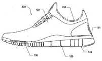
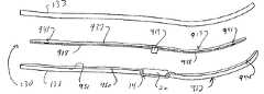
靴などのフットウェアが図1〜2に例として示され、一般に、参照番号100で指定されている。フットウェア100は、たとえば様々なタイプの競技フットウェアを含む多くの異なる形態をとることができる。一つの例示的態様において、靴100は一般に、汎用通信ポート14に動作可能に接続された力センサシステム12を含む。以下さらに詳細に説明するように、センサシステム12は、靴100の装用者に関するパフォーマンスデータを収集する。汎用通信ポート14への接続を介して、以下さらに詳細に説明するように、多数の異なるユーザが多様な用途のためにパフォーマンスデータにアクセスすることができる。 Footwear such as shoes is shown by way of example in FIGS. 1-2 and is generally designated by the
フットウェア製品100は、図1〜2において、アッパー120およびソール構造130を含むものとして示されている。以下の説明における参照のために、フットウェア100は、図1に示すように、三つの大まかな領域、すなわち前部領域111、中間領域112およびヒール領域113に分割されることができる。領域111〜113は、フットウェア100の厳密な区域を画定することを意図したものではない。むしろ、領域111〜113は、以下の説明において基準枠を提供する、フットウェア100の大まかな区域を表すことを意図したものである。領域111〜113は、一般にはフットウェア100に当てはまり、領域111〜113の参照はまた、特異的には、アッパー120、ソール構造130またはアッパー120もしくはソール構造130内に含まれる、および/またはその一部として形成される個々の部品に当てはまることもできる。 The
図1および2にさらに示すように、アッパー120は、ソール構造130に固着され、足を受容するための空隙またはチャンバを画定する。参照のために、アッパー120は、外側面121、反対側の内側面122および爪革または甲区域123を含む。外側面121は、足の外側面(すなわち外側)に沿って延びるように配置され、一般に、領域111〜113それぞれを通過する。同様に、内側面122は、足の反対側の内側面(すなわち内側)に沿って延びるように配置され、一般に、領域111〜113それぞれを通過する。爪革区域123は、外側面121と内側面122との間に配置されて、足の上面または甲区域と合致する。甲区域123は、この図示される例において、足に対してアッパー120の寸法を変え、それによりフットウェア100のフィット性を調節するために従来の様式で使用されるひも125または他の所望の閉止機構を有する舌革124を含む。アッパー120はまた、アッパー120内の空隙へのアクセスを足に提供するくるぶし開口部126を含む。アッパー120を構築するためには、フットウェアアッパーに従来から使用されている材料を含む多様な材料を使用することができる。したがって、アッパー120は、たとえば皮革、合成皮革、天然または合成織物、ポリマーシート、ポリマーフォーム、メッシュ織物、フェルト、不織ポリマーまたはゴム材料の一つまたは複数の部分から形成されることができる。アッパー120は、これらの材料の一つまたは複数から形成されることができ、その場合、該材料またはその部分は、たとえば当技術分野で従来から公知でありかつ使用されている様式で縫合または接着される。 As further shown in FIGS. 1 and 2, upper 120 is secured to
アッパー120はまた、ヒール要素(図示せず)およびトウ要素(図示せず)を含むことができる。ヒール要素は、存在する場合、ヒール領域113でアッパー120の内面に沿って上に延びて、フットウェア100の履き心地を高めることができる。トウ要素は、存在する場合、前部領域111中、アッパー120の外面に位置して、耐摩耗性を提供し、装用者のつま先を保護し、足の配置を支援することができる。いくつかの態様において、ヒール要素およびトウ要素の一方または両方がなくてもよく、ヒール要素が、たとえばアッパー120の外面に配置されてもよい。上記のアッパー120の構成はフットウェア100に適しているが、アッパー120は、本発明を逸脱することなく、任意の所望の従来または非従来のアッパー構造の構成を示すこともできる。
ソール構造130は、アッパー120の下面に固着され、一般に従来の形状を有することができる。ソール構造130は、マルチピース構造、たとえば、ミッドソール131、アウトソール132および、中敷き、ストローベル、インソール部材、ブーティー要素、底革などであってもよい足接触部材133を含む構造を有してもよい(図4〜5を参照)。図4〜5に示す態様において、足接触部材133はインソール部材である。本明細書で使用される語「足接触部材」とは、必ずしも、ユーザの足との直接的接触を意味するわけではなく、別の要素が直接的接触を妨げてもよい。むしろ、足接触部材は、フットウェア製品の足受けチャンバの内面の一部分を形成する。たとえば、ユーザは、直接接触を妨げるソックスを着用していてもよい。もう一つの例として、センサシステム12は、靴または他のフットウェア製品の上に嵌められるように設計されているフットウェア製品、たとえば外部ブーティー要素またはシューカバーに組み込まれることもできる。そのような製品において、ソール構造のアッパー部分は、ユーザの足と直接的には接触しないとしても、足接触部材とみなされることができる。 The
ミッドソール部材131は衝撃緩衝部材であることができる。たとえば、ミッドソール部材131は、ポリマーフォーム材料、たとえばポリウレタン、エチル酢酸ビニルまたは歩行、走行、ジャンプもしくは他の活動中に収縮して地面または他の接触面の反作用力を減衰させる他の材料(たとえばphylon、phyliteなど)で形成されることができる。本発明のいくつかの例示的な構造において、ポリマーフォーム材料は、フットウェア100の履き心地、動き制御、安定性および/または地面もしくは他の接触面の反作用力減衰性を高める様々な要素、たとえば流体充填ブラダまたは減速材を封入または包含することができる。さらに他の例示的構造においては、ミッドソール131は、収縮して地面または他の接触面の反作用力を減衰させるさらなる要素を含むこともできる。たとえば、ミッドソールは、力の緩衝および吸収を支援するための柱型要素を含むこともできる。 The
アウトソール132は、この図示される例示的フットウェア構造100においてはミッドソール131の下面に固着され、歩行または他の活動中に地面または他の面と接触する耐摩耗性材料、たとえばゴムまたは可撓性合成材料、たとえばポリウレタンで形成されている。アウトソール132を形成する材料は、適当な材料で製造される、および/または、高められたトラクションおよび耐滑り性を付与するためにテクスチャを施されることができる。アウトソール132を製造する構造および方法は以下さらに説明する。足接触部材133(インソール部材、中敷き、ブーティー要素、ストローベル、底革などであることができる)は、一般には、フットウェア100の履き心地を高めるために、アッパー120中の空隙内に、足の下面に隣接して(またはアッパー120とミッドソール131との間に)位置することができる薄い圧縮性部材である。いくつかの形態においては、インソールまたは中敷きがなくてもよく、他の態様において、フットウェア100は、インソールまたは中敷きの上に配置された足接触部材を有することもできる。
図1および2に示すアウトソール132は、アウトソール132のいずれか側または両側に複数の切り込みまたは溝136を含む。これらの溝136は、アウトソール132の底からその上部分またはミッドソール131まで延びることができる。一つの配置において、溝136は、アウトソール132の下面からアウトソール132の底とアウトソール132の上部との中間点まで延びることができる。もう一つの配置において、溝136は、アウトソール132の下面からアウトソール132の上部までの中間点を越えて延びることができる。さらに別の配置において、溝136は、アウトソール132の底からアウトソール132がミッドソール131と接触する点まで延びることができる。溝136は、アウトソール132にさらなる可撓性を提供することができ、それにより、アウトソールが装用者の足が撓む自然な方向により自由に撓むことを可能にする。加えて、溝136は、装用者に牽引性(traction)を提供することを支援することができる。本発明の態様は、他のタイプおよび構成の靴ならびに他のタイプのフットウェアおよびソール構造とともに使用することができることが理解されよう。 The
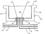
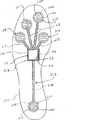
図3〜5は、本発明のセンサシステム12を組み込んだフットウェア100の例示的態様を示す。センサシステム12は、複数のセンサ16を有する力センサアセンブリ13およびセンサアセンブリ13と通信状態にある(たとえば、導体を介して電気的に接続された)通信または出力ポート14を含む。図3に示す態様において、システム12は、四つのセンサ16、すなわち、靴の親指(第一指節骨)区域にある第一のセンサ16A、靴の前部区域にある二つのセンサ16B〜C(第一中足骨頭領域にある第二のセンサ16Bおよび第五中足骨頭領域にある第三のセンサ16Cを含む)およびヒールにある第四のセンサ16Dを有する。足のこれらの区域は通常、運動中に最大度の圧力を受ける。以下に記載し、図27〜28に示す態様は、センサ16の類似した構成を使用する。各センサ16は、ユーザの足によってセンサ16に加えられた力を検出するように構成されている。センサは、ワイヤリードおよび/または別の電気導体もしくは適当な通信媒体であることができるセンサリード18を介してポート14と通信する。たとえば、一つの態様において、センサリード18は、インソール部材133、ミッドソール部材131またはソール構造130の別の部材、たとえば足接触部材133とミッドソール部材131との間の層にプリントされた導電媒体であることができる。 3-5 illustrate an exemplary embodiment of
センサシステム12の他の態様は、異なる数または構成のセンサ16、たとえば、以下に記載し、図8、11〜21および27〜28に示す態様を含み、一般に少なくとも一つのセンサ16を含むことができる。たとえば、一つの態様において、システム12は、より多数のセンサを含み、もう一つの態様において、システム12は、靴100のヒール内に一つおよび前部内に一つの、二つのセンサを含む。加えて、センサ16は、任意の公知のタイプの有線または無線通信、たとえばBluetoothおよび近接場通信を含む異なる様式でポート14と通信することができる。一対の靴は、それぞれの靴の中にセンサシステム12を提供されることができ、対になったセンサシステムは、相乗的に作動することもできるし、互いに独立して作動することもでき、また、各靴中のセンサシステムは、互いと通信してもよいし、しなくてもよいということが理解されよう。センサシステム12の通信は以下さらに詳細に説明する。センサシステム12は、データ(たとえば、ユーザの足と地面または他の接触面との相互作用からの圧力データ)の収集および記憶を制御するコンピュータプログラム/アルゴリズムを提供されることができること、また、これらのプログラム/アルゴリズムが、センサ16、モジュール22および/または外部装置110に記憶される、および/またはそれらによって実行されることができることが理解されよう。 Other embodiments of
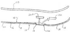
センサシステム12は、靴100のソール130中にいくつかの構成で配置されることができる。図4〜5に示す例において、ポート14、センサ16およびリード18は、たとえばポート14、センサ16および/またはリード18をミッドソール131の上面または足接触部材133の下面に接続することにより、ミッドソール131と足接触部材133との間に配置されることができる。ミッドソール131(図4)または足接触部材133(図5)中には、以下に記載するように、電子モジュールを受容するためのキャビティまたはウェル135が位置することができ、ポート14は、ウェル135内からアクセス可能である。図4に示す態様において、ウェル135は、ミッドソール131の上主面中の開口部によって形成され、図5に示す態様において、ウェル135は、インソール133の下主面中の開口部によって形成されている。ウェル135は、他の態様において、ソール構造130中の他の場所に位置することもできる。たとえば、ウェル135は、一つの態様において、足接触部材133およびミッドソール部材131の両方の中に部分的に位置することもできるし、またはウェル135は、ミッドソール131の下主面またはインソール133の上主面中に位置することもできる。さらなる態様において、ウェル135は、アウトソール132中に位置することもでき、靴100の外側から、たとえばソール130の側面、底またはヒール中の開口部を介してアクセス可能であることができる。図4〜5に示す構成において、ポート14は、以下に記載するように、電子モジュールの接続または切り離しのために容易にアクセス可能である。他の態様において、センサシステム12は異なって配置されることができる。たとえば、一つの態様において、ポート14、センサ16および/またはリード18は、アウトソール132、ミッドソール131またはインソール133内に配置されることができる。一つの例示的態様において、ポート14、センサ16および/またはリード18は、インソール133の上方に配置された足接触部材133、たとえば底革、中敷き、内部フットウェアブーティーまたは他の類似物品内に配置されることができる。さらなる態様において、ポート14、センサ16および/またはリード18は、たとえば図12および19〜20に示すように、足接触部材133とミッドソール131との間に速やかかつ容易に挿入可能であるように設計されたインサートまたはライナ中に形成されることができる。さらに他の構成が可能であり、他の構成のいくつかの例を以下に記載する。説明したように、センサシステム12は対の各靴の中に含めることができることが理解されよう。 The
一つの態様において、センサ16は、ソール130の収縮および/またはソール130上の力を計測するための力センサである。たとえば、センサ16は、感圧抵抗(FSR)センサまたは感圧抵抗材料(たとえば、以下さらに詳細に説明する量子トンネリング複合材、カスタム(custom)導電性フォームまたは力変換性ゴム)を使用する他のセンサ、磁気抵抗センサ、圧電またはピエゾ抵抗センサ、ひずみゲージ、ばね式センサ、光ファイバ式センサ、偏光センサ、機械的アクチュエータ式センサ、変位式センサおよび足接触部材133、ミッドソール131、アウトソール132などの収縮を計測することができる任意の他のタイプの公知のセンサまたはスイッチであることができる。センサは、力を定量的に計測するアナログ装置または他の装置であることもできるし、単にバイナリタイプON/OFFスイッチ(たとえばシリコーン膜タイプスイッチ)であることもできる。センサによる力の定量的計測には、電子装置、たとえばモジュール22または外部装置110によって定量的力計測値に変換されることができるデータを集めて送信することを含みうることが理解されよう。本明細書に記載されるようないくつかのセンサ、たとえばピエゾセンサ、感圧抵抗センサ、量子トンネリング複合材センサ、カスタム導電性フォームセンサなどは、抵抗、キャパシタンスまたは電位の差または変化を計測し、計測した差を力成分に変換することができる。上述したばね式センサは、圧力および/または変形によって生じる抵抗の変形または変化を計測するように構成されていることができる。上記の光ファイバ式センサは、圧縮可能な管ならびにそれに接続された光源および光計測装置を含む。このようなセンサにおいては、管が圧縮されると、管内の光の波長が変化し、計測装置は、そのような変化を検出し、その変化を力計測値に変換することができる。ナノコーティングを使用することもでき、たとえばミッドソールを導電材料に浸漬することもできる。偏光センサを使用することもでき、その場合、光透過性の変化が計測され、ソールに加わる圧力または力に相関させられる。一つの態様は、多重アレイ(たとえば100個)のバイナリon/offセンサを使用し、力成分は、特定区域におけるセンサ信号の「パドリング」によって検出されることができる。本明細書では挙げられていないさらに他のタイプのセンサを使用することもできる。センサは、比較的安価であることができ、大量生産工程で靴の中に配置することができることが理解されよう。より高価であるかもしれない、より複雑なセンサシステムをトレーニングタイプの靴に組み込むこともできる。 In one embodiment,
さらには、センサ16を、多くの様々な様式で靴構造と係合させて配置することができる。一例において、センサ16は、ソール部材、たとえばエアバッグまたは他の流体充填チャンバ、フォーム材料もしくは靴100に使用される別の材料または底革、ブーティー、インサート、ライナ、インソール、ミッドソールなどに付着させたプリント導電インクセンサ、電極および/またはリードであることもできる。センサ16および/またはリード18は、衣服または布構造を織る、または編むとき、たとえば導電性布または糸を使用して衣服または布構造(たとえば中敷き、ブーティー、アッパー、インサートなど)に織り込むこともできる。センサシステム12の多くの態様は、たとえば、以下に記載し、図8および11〜21に示す感圧抵抗センサまたは感圧抵抗材料を使用することにより、安価に製造することができる。センサ16および/またはリード18はまた、任意の所望の様式で、たとえば従来の付着技術、導電性ナノコーティング、従来の機械的コネクタおよび任意の他の適用可能な公知の方法により、靴構造の一部分に付着または靴構造の一部分と係合させることもできる。センサシステムはまた、機械的フィードバックを装用者に提供するように構成されていることもできる。さらには、センサシステム12は、センサ16にパワーを供給するための別個のパワーリードを含むことができる。以下に記載し、図5A〜5Eおよび図27〜28に示す態様において、センサシステム12、1312は、センサ16、1316をポート14、14A〜Eに接続してモジュール22からセンサ16、1316にパワーを供給するために使用される別個のパワーリード18A、1318Aを含む。さらなる例として、センサシステム12は、導電インクセンサ16のプリントまたは電極および導電性布または糸リード18を組み込むことによって、またはそのようなセンサを靴のフォームまたはエアバッグ上に形成することによって製造することができる。センサ16は、多様な様式でエアバッグに組み込むことができる。一つの態様において、センサ16は、導電性の感圧材料をエアバッグの一つまたは複数の面にプリントしてひずみゲージ様効果を達成することによって製造することもできる。活動中にバッグが膨張および/または収縮すると、センサが、感圧材料の抵抗の変化を介してそのような変化を検出して、エアバッグにかかる力を検出することができる。一貫した形状を維持するための内部布を有するバッグにおいては、エアバッグの上下に導電材料を配置し、バッグが膨張し、収縮するときの導電性材料の間のキャパシタンスの変化を使用して力を測定することができる。さらには、空気圧の変化を電気信号に変換することができる装置を使用して、エアバッグが圧縮されるときの力を測定することもできる。 Furthermore, the
ポート14は、一つまたは複数の公知の様式で、センサ16によって収集されたデータの外部ソースへの通信のために構成されている。一つの態様において、ポート14は、普遍的に読み取り可能なフォーマットでのデータ通信のために構成された汎用通信ポートである。図3〜5に示す態様において、ポート14は、図3においてポート14と接続状態に示される電子モジュール22への接続のためのインタフェース20を含む。図3〜5に示す態様において、インタフェース20は電気接点の形態をとる。さらには、この態様において、ポート14は、フットウェア製品100の土踏まずまたはミッドフット領域のウェル135中に位置する、電子モジュール22の挿入のためのハウジング24と対応している。図3〜5に示すポート14の配置は、ユーザの足への最小限の接触、刺激または他の干渉を提示するだけでなく、単にインソール133を持ち上げることによる容易なアクセス性を提供する。さらには、図6に示すように、センサリード18はまた、ポート14に接続するために、末端に統合インタフェースを形成している。一つの態様において、統合インタフェースは、たとえば複数の電気接点を介する、ポートインタフェース20へのセンサリード18の個々の接続を含むことができる。もう一つの態様において、センサリード18は、外部インタフェース19、たとえば以下に記載するプラグタイプインタフェースを形成するためまたは別の様式で統合されることもでき、さらなる態様において、センサリード18は、各リード18がそれ自体のサブインタフェースを有する非統合インタフェースを形成することもできる。図6に示すように、センサリード18は、一つの場所に集束して統合インタフェースを形成することができる。同じく以下に記載するように、モジュール22は、ポートインタフェース20および/またはセンサリード18への接続のためのインタフェース23を有することもできる。
ポート14は、簡単なものとしてはメモリコンポーネント(たとえばフラッシュドライブ)であることもでき、より複雑な特徴を含むものであることもできる多様な電子モジュール22への接続に適合している。モジュール22は、パーソナルコンピュータ、モバイル装置、サーバなどのような複雑なコンポーネントであってもよいことが理解されよう。ポート14は、センサ16によって集められたデータを記憶および/または処理のためにモジュール22に送信するように構成されている。フットウェア製品中のハウジングおよび電子モジュールの例が、参照により本明細書に組み入れられ、その一部とされる米国特許出願第11/416,458号(米国特許出願公開公報第2007/0260421として公開)に示されている。ポート14は、モジュールへの接続のためのインタフェース20を形成する電子接点を有する状態で示されているが、ポート14は、一つまたは複数のさらなるまたは代替の通信インタフェースを含むこともできる。たとえば、ポート14は、USBポート、FireWireポート、16ピンポートまたは他のタイプの物理接触式の接続を含むこともできるし、無線または無接点通信インタフェース、たとえばWi-Fi、Bluetooth、近接場通信、RFID、Bluetooth Low Energy、Zigbeeもしくは他の無線通信技術のためのインタフェースまたは赤外線もしくは他の光学通信技術のためのインタフェースを含むこともできる。
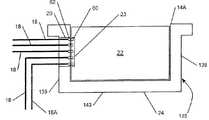
センサリード18は、多様な構成でポート14に接続されることができる。図5A〜5Eは、フットウェア製品100中のウェル135内、たとえば上記のようにソール構造130のソール部材内に配置されたポート14A〜Eの例示的態様を示す。図5A〜5Eに示す態様において、ウェル135は、側壁139およびベース壁143を含む複数の壁を有する。 The
図5Aは、四つのセンサリード18およびパワーリード18Aがウェル135の一つの側壁139を介してポート14Aに接続されているポート14Aの態様を示す。図示される態様において、センサリード18は、ポート14Aのインタフェース20に接続される、5ピン接続の形態の統合インタフェースを形成する。この構成において、リード18、18Aはポートインタフェース20に接続されて統合インタフェースを形成し、リード18、18Aのぞれぞれは接続ピン62で終端してマルチピン接続を形成する。一つの態様において、この接続ピン62は、ウェル135内でアクセス可能なリード18、18Aの露出端とみなすことができる。同様に、モジュール22は、ポートインタフェース20中のリード18、18Aの接続ピン62への接続のための五つのピン接続60を含む接続23を有する。 FIG. 5A shows an embodiment of
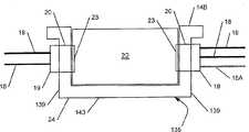
図5Bは、二つのセンサリード18がウェル135の側壁139の一方を介してポート14Bに接続されており、二つの他のセンサリード18およびパワーリード18Aが側壁139のもう一方を介してポート14Bに接続されているポート14Bの態様を示す。この態様において、リード18は、外部インタフェース19の形態の二つの別々の統合リードインタフェース19を形成し、ポート14Bは、リード18、18Aへの接続のための二つの別々のインタフェース20を有する。外部インタフェース19は、プラグタイプインタフェース、ピンタイプインタフェースまたは他のインタフェースであることができ、ポートインタフェース20は、外部リードインタフェース19に接続するために相補的に構成されている。さらには、この構成において、モジュール22は、ポートインタフェース20への接続のために構成された二つのインタフェース23を有する。 FIG. 5B shows that two sensor leads 18 are connected to port 14B through one of the
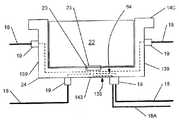
図5Cは、センサリード18およびパワーリード18Aがウェル135の側壁139およびベース壁143を介してポート14Cに接続されているポート14Cの態様を示す。この態様において、センサリード18は、ポート14Cへの接続のためのいくつか別々のリードインタフェース19を形成する。ポート14Cは、モジュールインタフェース23への接続のために、ポートインタフェース20へのすべてのリード18、18Aの接続を統合する内部回路64を含む。ポート14Cはさらに、リードインタフェース19それぞれに対する接続のための相補的インタフェースを含むことができる。リード18、18Aは、この態様において、ウェル135の側壁139の一つまたは複数を介して接続されてもよく、リード18、18Aは、例示目的のために、側壁139の二つを介して接続された状態で示されていることが理解されよう。また、この態様において、二本以上のリード18、18Aがウェル135の特定の側壁139を介して接続されてもよいこと、および、たった一本のリード18、18Aがベース壁143を介して接続されてもよいことが理解されよう。 FIG. 5C shows an embodiment of
図5Dは、四つのセンサリード18およびパワーリード18Aがウェル135のベース壁143を介してポート14Dに接続されているポート14Dの態様を示す。図示される態様において、リード18、18Aは、上記し、図5Aに示す接続と類似した構成で、ポート14Dの底にあるインタフェース20に接続される統合インタフェースを形成する。リード18、18Aそれぞれは、ポートインタフェース20における接続ピン62で終端し、モジュールインタフェース23は、リード18、18Aの接続ピン62への接続のために構成された複数のピン接続60を含む。 FIG. 5D shows an embodiment of
図5Eは、四つのセンサリード18およびパワーリード18Aがウェル135の四つの側壁139それぞれを介してポート14Eに接続されているポート14Eの態様を示す。この態様において、リード18、18Aは、上記し、図5Cに示す態様と同様に、ポート14Eへの接続のためのいくつかの別々のインタフェース19を形成する。上記のように、ポート14Eは、リードインタフェース19への接続のための相補的インタフェースを含むことができ、また、モジュール22への接続のためのインタフェースを含むことができる。他の態様において、リード18、18Aは、ウェル135の側壁139のいくつかを介して接続することができる。 FIG. 5E shows an embodiment of
センサ18が一つより多いインタフェース19を形成する、図5B、5Cおよび5Eに示す態様のような態様において、ポート14B、14C、14Eおよび/またはモジュール22は、多数のインタフェース20、23を有することもできるし、または一つのインタフェース20、23しか有しないこともでき、ポート14は、すべてのリード18、18Aをインタフェース20、23に接続するための内部回路64を有することができる。さらには、モジュール22は、ポート14のインタフェース20に対して相補的である、それへの接続のための一つまたは複数のインタフェース23を有することができる。たとえば、ポート14がその側壁139および/またはベース壁143にインタフェース20を有するならば、モジュール22は、同じく側壁および/またはベース壁に相補的なインタフェース23を有することができる。モジュール22およびポート14は、同一に相補的なインタフェース20、23を有しなくてもよく、相補的インタフェース20、23の一対だけがコンポーネント間の通信を達成することができてもよいということが理解されよう。他の態様において、ポート14およびウェル135は、リード18、18Aの接続のための異なる構成を有することもできる。さらには、ポート14は、より多様な接続構成を可能にする異なる形状を有することもできる。さらには、本明細書に記載される接続構成のいずれかまたはそれらの組み合わせを、本明細書に記載されるセンサシステムの様々な態様とともに使用することができる。 In an embodiment such as the embodiment shown in FIGS. 5B, 5C and 5E, in which the
モジュール22はさらに、以下に記載し、図6に示すように、データを処理のために送信するために外部装置110に接続するための一つまたは多数の通信インタフェースを有することができる。このようなインタフェースは、上記の有接点または無接点インタフェースのいずれかを含むことができる。一例において、モジュール22は、少なくとも、コンピュータへの接続のための格納式USB接続を含む。もう一つの例において、モジュール22は、モバイル装置、たとえば時計、携帯電話、ポータブル音楽プレーヤなどへの有接点または無接点接続のために構成されていることもできる。モジュール22は、データ転送のために、フットウェア100から取り外されて、たとえば上記格納式USB接続によって外部装置110に直接接続されるように構成されていることができる。しかし、もう一つの態様において、モジュール22は、装置22がフットウェア100中に残ることを可能にする、外部装置110との無線通信のために構成されていることもできる。無線態様において、モジュール22は、無線通信のためのアンテナに接続されることができる。アンテナは、選択された無線通信法に適切な送信周波数での使用のために形成、サイズ決定および配置されることができる。さらには、アンテナは、モジュール22内部に位置してもよいし、モジュールに対して外部に位置してもよい。一例において、センサシステム12そのもの(たとえば、センサ16のリード18および導電部分)を使用してアンテナを形成することもできる。一つの態様において、モジュール22は、フットウェア100内に永久的に取り付けられてもよいし、または、ユーザの選択で取り外し可能であり、望むならばフットウェア100中に残されてもよい。さらには、以下さらに説明するように、モジュール22は、取り外され、別の様式でセンサ16からのデータを収集および/または使用するようにプログラムおよび/または構成された別のモジュール22と交換されることもできる。モジュール22がフットウェア100内に永久的に取り付けられるならば、センサシステム12は、図7に示すように、データ転送および/またはバッテリ充電を可能にするための外部ポート15、たとえばUSBまたはFireWireポートをさらに含むことができる。モジュール22は、有接点通信および無接点通信の両方のために構成されていることができることが理解されよう。
本発明を逸脱することなくポート14を多様な位置に配置することができるが、一つの態様において、ポート14は、たとえば競技活動中に装用者が履くときおよび/またはそれ以外でフットウェア製品100を使用するときなどの装用者の足への接触および/または刺激を回避するか最小限にするような位置および向きで提供され、かつ/またはそれ以外の様式で構築されている。図3〜5のポート14の配置は一つのそのような例を示す。もう一つの態様において、ポート14は靴100のヒールまたは甲領域の近くに位置している。フットウェア構造100の他の特徴は、装用者の足とポート14(またはポート14に接続された要素)との接触を減らし、または避け、フットウェア構造100の全体的履き心地を改善することに役立つことができる。たとえば、図4〜5に示すように、インソール133または他の足接触部材は、ポート14の上に嵌り、ポート14を少なくとも部分的に覆って、それにより、装用者の足とポート14との間に詰め物の層を提供することもできる。ポート14と装用者の足との接触を減らし、装用者の足におけるポート14の望ましくない感覚を緩和するためのさらなる特徴を使用することもできる。当然、望むならば、本発明を逸脱することなく、ポート14の開口部をインソール部材133の上面に提供することもできる。そのような構造は、たとえば、ハウジング24、電子モジュール22およびポート14の他の特徴が、使用者の足における感覚を緩和するための構造を含む、および/またはそのための材料でできている場合、さらなる履き心地および感覚緩和要素が提供されている場合などに使用することができる。本発明を逸脱することなく、装用者の足とハウジング(またはハウジング中に受容された要素)との接触を減らし、または避け、フットウェア構造の全体的な履き心地を改善するのに役立つ上記様々な特徴のいずれかを、図4〜5に関連して先に記載した様々な特徴ならびに他の公知の方法および技術を含め、提供することができる。 Although the
ポート14が、ソール構造130中のウェル135に含まれるモジュール22との有接点通信のために構成されている一つの態様において、ポート14は、モジュール22への接続のために、ウェル135の内部または隣に配置される。ウェル135がモジュール22のためのハウジング24をさらに含むならば、ハウジング22は、たとえばポート14のための物理的空間を提供することにより、またはポート14とモジュール22との間の相互接続のためのハードウェアを提供することにより、ポート14への接続のために構成されていることもできる。図3におけるポート14の配置は、ハウジング24が、モジュール22への接続のためのポート14を受容するための物理的空間を提供する一つのそのような例を示す。 In one embodiment where the
図6は、本発明の少なくともいくつかの例にしたがって使用することができる、データ送受信システム106を介するデータ送受信能力を含む例示的な電子モジュール22の略図を示す。図6の例示的構造は、電子モジュール構造22に統合されたものとしてのデータ送受信システム(TX-RX)106を示すが、当業者は、別個のコンポーネントをフットウェア構造100またはデータ送受信目的のための他の構造の一部として含めることもできること、および/または本発明のすべての例においてデータ送受信システム106全部が一つのハウジングまたは一つのパッケージに含まれなくてもよいということを理解するであろう。むしろ、望むならば、データ送受信システム106の様々なコンポーネントまたは要素は、異なるハウジング中で、異なるボード上で、および/または、本発明から逸脱することなく様々な異なる様式でフットウェア製品100もしくは他の装置と別々に係合させて、互いに分離していてもよい。様々な潜在的な取り付け構造の様々な例を以下にさらに詳細に説明する。 FIG. 6 shows a schematic diagram of an exemplary
図6の例において、電子コンポーネント22は、一つまたは複数の遠隔システムとの間でデータを送受信するためのデータ送受信要素106を含むことができる。一つの態様において、送受信要素106は、たとえば上記有接点または無接点インタフェースにより、ポート14を介する通信のために構成されている。図6に示す態様において、モジュール22は、ポート14および/またはセンサ16への接続のために構成されたインタフェース23を含む。図3に示すモジュール22において、インタフェース23は、ポート14と接続するために、ポート14のインタフェース20の接点と相補的である接点を有する。上記のような他の態様において、ポート14およびモジュール22は、有線または無線であることができる様々なタイプのインタフェース20、23を含むことができる。いくつかの態様において、モジュール22は、TX-RX要素106を介してポート14および/またはセンサ16とインタフェースすることができることが理解されよう。したがって、一つの態様において、モジュール22はフットウェア100に対して外部にあることができ、ポート14は、モジュール22との通信のための無線送信インタフェースを含むことができる。この例の電子コンポーネント22はさらに、処理システム202(たとえば一つまたは複数のマイクロプロセッサ)、メモリシステム204および電源206(たとえばバッテリまたは他の電源)をさらに含む。 In the example of FIG. 6, the
一つまたは複数のセンサへの接続は、TX-RX要素106を介して達成することができるが、多種多様なタイプのパラメータに関するデータまたは情報、たとえばフットウェア製品100の使用またはユーザに関連する物理的または生理学的データ、たとえば、歩数計タイプスピードおよび/または距離情報、他のスピードおよび/または距離データセンサ情報、温度、高度、気圧、湿度、GPSデータ、加速度計出力もしくはデータ、心拍数、脈拍、血圧、体温、EKGデータ、EEGデータ、角配向および角配向の変化に関するデータ(たとえばジャイロスコープベースのデータ)などを感知または提供するために、さらなるセンサ(図示せず)が設けられてもよく、このデータは、メモリ204に記憶されることもできるし、たとえば、送受信システム106によって遠隔の場所またはシステムに送信されることもできる。さらなるセンサはまた、存在するならば、加速度計を含むことができる(たとえば、ステップ中の方向変化を感知するため、たとえば歩数計タイプスピードおよび/または距離情報のため、ジャンプ高さを感知するためなど)。 Connection to one or more sensors can be accomplished via TX-
さらなる例として、上記様々なタイプの電子モジュール、システムおよび方法は、フットウェア製品の自動衝撃減衰制御を提供するために使用することができる。このようなシステムおよび方法は、たとえば、フットウェア製品の衝撃減衰特性をアクティブおよび/またはダイナミックに制御するためのシステムおよび方法を記載する米国特許第6,430,843号、米国特許出願公開公報第2003/0009913号および米国特許出願公開公報第2004/0177531号に記載されているものと同様に作動することができる(それぞれ参照により全体として本明細書に組み入れられ、その一部とされる米国特許第6,430,843号、米国特許出願公開公報第2003/0009913号および米国特許出願公開公報第2004/0177531号)。スピードおよび/または距離タイプ情報を提供するために使用される場合、米国特許第5,724,265号、第5,955,667号、第6,018,705号、第6,052,654号、第6,876,947号および第6,882,955号に記載されているタイプの感知ユニット、アルゴリズムおよび/またはシステムを使用することができる。これらの特許それぞれは参照により全体として本明細書に組み入れられる。 As a further example, the various types of electronic modules, systems and methods described above can be used to provide automatic shock attenuation control for footwear products. Such systems and methods are described, for example, in US Pat. No. 6,430,843 and US Patent Application Publication No. 2003/0009913 which describe systems and methods for actively and / or dynamically controlling the impact damping characteristics of footwear products. And U.S. Patent Application Publication No. 2004/0177531, each of which is incorporated herein by reference in its entirety and is incorporated herein by reference. US Patent Application Publication No. 2003/0009913 and US Patent Application Publication No. 2004/0177531). Sensing of the type described in US Pat. Nos. 5,724,265, 5,955,667, 6,018,705, 6,052,654, 6,876,947 and 6,882,955 when used to provide speed and / or distance type information Units, algorithms and / or systems can be used. Each of these patents is incorporated herein by reference in its entirety.
さらに図6に示すように、電子モジュール22はアクティブ化システム(図示せず)を含むことができる。アクティブ化システムまたはその部分は、モジュール22またはフットウェア製品100(または他の装置)と、電子モジュール22の他の部分とともに、またはそれとは別に、係合させることができる。アクティブ化システムは、電子モジュール22および/または電子モジュール22の少なくともいくつかの機能(たとえばデータ送受信機能など)を選択的にアクティブ化するために使用することができる。本発明を逸脱することなく、多種多様なアクティブ化システムを使用することができ、様々な含まれる図面を参照しながらそのような多様なシステムを以下さらに詳細に説明する。一例において、センサシステム12は、センサ16を特定のパターン、たとえば連続的または交互のトウ/ヒールタップでアクティブ化することによってアクティブ化および/または非アクティブ化することができる。もう一つの例において、センサシステム12は、モジュール22上、靴100上またはセンサシステム12と通信状態にある外部装置上および他の場所に位置することができるボタンまたはスイッチによってアクティブ化することができる。これらの態様のいずれにおいても、センサシステム12は、一定の不活動期間ののちシステム12を非アクティブ化することができる「スリープ」モードを含むことができる。代替態様において、センサシステム12は、アクティブ化または非アクティブ化しない低パワー装置として作動することもできる。 Further, as shown in FIG. 6, the
モジュール22はさらに、図6に示すように、外部コンピュータもしくはコンピュータシステム、モバイル装置、ゲームシステムまたは他のタイプの電子装置であることができる外部装置110との通信のために構成されていることもできる。図6に示す例示的な外部装置110は、プロセッサ302、メモリ304、電源306、表示装置308、ユーザ入力310およびデータ送受信システム108を含む。送受信システム108は、上記および本明細書の他どこかに記載された有接点および無接点通信方法を含む任意のタイプの公知の電子通信により、モジュール22の送受信システム106を介するモジュール22との通信のために構成されている。モジュール22は、多種多様なタイプおよび構成の電子装置を含む複数の外部装置との通信のために構成されていることができる。さらには、モジュール22の送受信システム106は、複数の異なるタイプの電子通信のために構成されていることができる。さらに、靴100は、必要ならばセンサ16を作動させるための別個の電源、たとえばバッテリ、圧電、ソーラー電源などを含むことができることが理解されよう。センサ16はまた、モジュール22への接続のみを介して電力を受容することもできる。
上記のように、多くの異なるタイプのセンサが本発明のセンサシステムに組み込まれることができる。図8は、複数の感圧抵抗(FSR)センサ216を組み込んだセンサアセンブリ213を含むセンサシステム212を含む靴100の一つの例示的態様を示す。センサシステム212は、上記センサシステム12に類似しており、また、電子モジュール22と通信状態にあるポート14およびFSRセンサ216をポート14に接続している複数のリード218を含む。モジュール22は靴100のソール構造130中のウェルまたはキャビティ135内に収容され、ポート14はウェル135に接続されて、ウェル135内のモジュール22への接続を可能にする。ポート14およびモジュール22は、接続および通信のための相補的なインタフェース220、223を含む。 As noted above, many different types of sensors can be incorporated into the sensor system of the present invention. FIG. 8 illustrates one exemplary embodiment of a
図8に示す感圧抵抗は、第一および第二の電極または電気接点240、242ならびに電極240、242の間に配置されて電極240、242を電気的に接続している感圧抵抗材料244を含む。圧力が感圧材料244に加わると、感圧材料244の抵抗率および/または導電率が変化し、それが電極240、242の間の電位を変化させる。抵抗の変化がセンサシステム212によって検出されて、センサ216に加えられた力を検出する。感圧抵抗材料244は、圧力下、その抵抗を多様な方法で変化させることができる。たとえば、感圧材料244は、以下さらに詳細に説明する量子トンネリング複合材と同様に、材料が圧縮されたときに低下する内部抵抗を有することができる。この材料のさらなる圧縮は、抵抗をさらに減らして、定量的計測およびバイナリ(on/off)計測を可能にすることができる。いくつかの状況において、このタイプの感圧抵抗挙動は「体積ベースの抵抗」と記すことができ、この挙動を示す材料は「スマート材料」と呼ぶことができる。もう一つの例として、材料244は、面対面接触の程度を変化させることにより、抵抗を変化させることができる。これは、いくつかの方法で、たとえば非圧縮状態では表面抵抗を高め、圧縮されると表面抵抗を減らす、表面上の微小突起を使用することにより、または、変形して別の電極との面対面接触の増大を生じさせることができる可撓性電極を使用することにより、達成することができる。この表面抵抗は、材料244と電極240、242との間の抵抗および/または多層材料244の導電層(たとえば炭素/グラファイト)と感圧層(たとえば半導体)との間の表面抵抗であることができる。圧縮が大きくなればなるほど、面対面接触は大きくなり、より低い抵抗を生じさせ、定量的計測を可能にする。いくつかの状況において、このタイプの感圧抵抗挙動は「接触ベースの抵抗」と記すことができる。本明細書で定義される感圧抵抗材料244は、ドープされた、またはドープされていない半導体材料である、またはそれを含むことができることが理解されよう。 The pressure sensitive resistance shown in FIG. 8 is a pressure
FSRセンサ216の電極240、242は、金属、炭素/グラファイト繊維または複合材、他の導電性複合材、導電性ポリマーまたは導電性材料を含むポリマー、導電性セラミックス、ドープされた半導体または他の導電性材料を含む任意の導電性材料で形成されていることができる。リード218は、溶接、はんだ付け、ろう付け、接着、ファスナまたは他の一体的または非一体的接合法を含む任意の適当な方法によって電極240、242に接続されることができる。または、電極240、242および対応するリード218は、同じ材料の単一材料片で形成されることもできる。 The
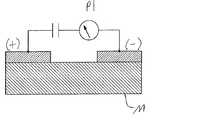
図9〜10は一般に、センサ16、たとえば図8に示すFSRセンサ216における感圧抵抗材料Mの使用を示す。電極(+)および(−)は、図9に示すように、それらの間に電位P1を有する。感圧抵抗材料Mが圧縮されると、図10に示すように、材料Mの抵抗が変化し、ひいては、電極(+)および(−)の間の電位P2が変化する。材料Mは、体積ベースの抵抗、接触ベースの抵抗または他のタイプの感圧抵抗挙動を使用することができる。たとえば、図8のセンサ216の感圧抵抗材料244はこのように挙動することができる。もう一つの例として、量子トンネリング複合材、カスタム導電性フォーム、力変換性ゴムおよび以下に記載し、図16〜20に示す他の感圧抵抗材料が感圧抵抗挙動を示す。電極(+)および(−)は、異なる構造、たとえば材料Mが電極(+)および(−)の間に配置されたサンドイッチ構造に配置されることもできる。 9-10 generally illustrate the use of pressure sensitive resistance material M in
図8に示す例示的態様において、FSRセンサ216の電極240、242は、インタロックしたまたはかみ合った複数のフィンガ246を有し、感圧抵抗材料244がそれらのフィンガ246の間に配置されて電極240、242を互いに電気的に接続している。図8に示す態様において、各リード218は、独立して、モジュール22からのパワーを、各リード218が接続されているセンサ216に供給する。センサリード218は、各電極240、242からポート14に延びる別々のリードを含むことができ、モジュール22がそのような別々のリードを介して、たとえば本明細書の他の場所で記載される別々のパワーリード18A、1318Aを介して電力を電極240、242に提供することができることが理解されよう。 In the exemplary embodiment shown in FIG. 8, the
センサシステム212における使用に適した感圧抵抗器は、Sensitronics LLCのような供給元から市販されている。使用に適することができる感圧抵抗器の態様は、参照により全体として本明細書に組み入れられ、その一部とされる米国特許第4,314,227号および第6,531,951号に示され、記載されている。 Pressure sensitive resistors suitable for use in
図27〜28は、フットウェア製品100に組み込まれるFSRセンサシステム1312のもう一つの態様を示す。センサシステム1312は四つのセンサ1316を含み、図3に示す構成と同様に、第一のセンサ1316が第一指節骨(親指)区域に配置され、第二のセンサ1316が第一中足骨頭区域に配置され、第三のセンサ1316が第五中足骨頭区域に配置され、第四のセンサ1316がヒール区域に配置されている。センサ1316はそれぞれ、センサ1316をポート14に接続しているセンサリード1318を有する。さらには、パワーリード1318Aがポート14から延び、四つすべてのセンサ1316に直列に接続されて、四つすべてのセンサ1316にパワーを供給する。同様に、並列を含む他の構成が可能である。図28に示すように、リード1318、1318Aはそれぞれ、ポート14に接続されたモジュール(図示せず)への接続およびデータ伝送のために、ポート14に接続されている。ポート14は、本明細書に記載される任意の構成を有することができることが理解されよう。この態様において、リード1318、1318Aは、複数の接続ピン62により、図5Aに示すような5ピン接続に適するように配置されている。 FIGS. 27-28 illustrate another embodiment of an
図8に関連して上記したシステム212と同様に、センサシステム1312の各センサ1316は、第一および第二の電極または電気接点1340、1342ならびに電極1340、1342の間に配置されて電極1340、1342を電気的に接続している感圧抵抗材料1344を含む。圧力が感圧材料1344に加わると、感圧材料1344の抵抗率および/または導電率が変化し、それが電極1340、1342の間の電位を変化させる。抵抗の変化がセンサシステム1312によって検出されて、センサ1316に加えられた力を検出する。さらには、FSRセンサ1316はそれぞれ、インタロックする、またはかみ合った複数のフィンガ1346を有し、感圧抵抗材料1344がそれらのフィンガ1346の間に配置されて電極1340、1342を互いに電気的に接続している。 Similar to
図27〜28に示すセンサシステム1312の態様において、各センサ1316は、導電性金属層および金属層上に接触面を形成する炭素層(たとえばカーボンブラック)で構築された二つの接点1340、1342を含む。センサ1316はまた、電極1340、1342の炭素接触面と接触している、同じく炭素(たとえばカーボンブラック)の層またはパドルで構築された感圧抵抗材料1344を含む。炭素対炭素接触は、圧力下、より大きな導電率変化を生じさせて、センサ1316の有効性を増すことができる。この態様におけるリード1318、1318Aは、接点1340、1342の金属層の材料と同じであってもよい導電性金属材料で構築されている。一つの態様において、リード1318、1318Aおよび接点1340、1342の金属層は銀で構築されている。 In the embodiment of
図27〜28に示すように、この例示的態様において、センサシステム1312は、以下に記載するように、フットウェア製品に、たとえば足接触部材133とミッドソール部材131との間に挿入されるインサート部材1337を形成するように組み合わされる二つの可撓性層1366および1368で構築されている。層は、任意の可撓性材料、たとえば可撓性ポリマー材料で形成されることができる。一つの態様において、層1366、1368は、厚さ0.05〜0.2mmの柔軟な薄いMylar材料で形成されている。インサート1337は、まず、導電性金属材料をたとえばプリントによってセンサ1316のリード1318、1318Aおよび電極1340、1342のトレースパターンで第一の層1366に付着させて、図27に示す構成を形成することによって構築される。次に、同じく図27に示すように、さらなる炭素接触層を、センサ1316の電極1340、1342の上にトレースしながら第一の層1366に付着させ、炭素感圧抵抗材料1344をパドルとして第二の層1368に付着させる。すべての材料を付着させたのち、図28に示すように、層1366、1368を重ねるように配置して、電極1340、1342を感圧抵抗材料1344のパドルと整合させて、フットウェア製品100に挿入するためのインサート部材1337を形成する。一つの態様において、このようにして構築されたセンサシステム1312は、10〜750kPaの範囲の圧力を高い感度で検出することができる。 As shown in FIGS. 27-28, in this exemplary embodiment, the
図8および27〜28に示すセンサシステム212、1312は、図4および5に示すように、靴100の中、足接触部材133とミッドソール部材131との間で具現化されることができる。一つの態様において、FSRセンサシステム212、1312は、靴100の製造中、アッパー120をミッドソール131およびアウトソール132に接続したのち、ミッドソール部材131の上方(および、存在するならば、ストローベルの上方)に挿入される。その後、足接触部材133をセンサシステム212、1312の上に挿入することができる。さらには、一つの態様において、センサシステム212、1312は、インサート部材、たとえば図12および27〜28に示すインサート部材437および1337の一部として挿入することもできる。図11〜14は、FSRセンサをフットウェア製品、たとえば靴100の中に具現化するさらなる例を示す。図11〜14に示す態様は、先に記載し、図4に示すように、電子モジュール22を受容するためのウェル135をその内部に、およびモジュール22への接続のためのポート14を有する、ミッドソール部材131を示す。しかし、ウェル135および/またはポート14は、他の場所に、たとえば図5に示すように全部または一部が足接触部材133内に、または靴100中の他の場所に配置されてもよいことが理解されよう。 The
一例として、図11は、ミッドソール部材131がそれに接続されたFSRセンサアセンブリ313を有する、FSRセンサシステム312を含むフットウェア製品のソール構造130の一部分を示す。この態様において、FSRセンサ316は、ミッドソール部材131内に部分的に埋め込まれ、センサリード318は、ミッドソール部材131の上面に接続されている。ミッドソール部材131は、センサ316を覆ってセンサをミッドソール部材131内に保持する層を有することができ、センサ318は、全部または一部がミッドソール部材131内に埋め込まれることができ、または、ミッドソール部材131がセンサ316の挿入のための「ポケット」を有することができることが理解されよう。ミッドソール部材131はまた、それに接続されたポート14を有する。ポート14は、センサリード318に接続され、ウェル135内に受容された電子モジュール22との接続のためにウェル135内に配置される。センサリード318は、ポート14への接続のためのインタフェース319をポート14の近くに形成する。 As an example, FIG. 11 shows a portion of a footwear product
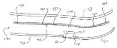
もう一つの例として、図12は、さらなるソール部材437がFSRセンサアセンブリ413を含む、FSRセンサシステム412を含むフットウェア製品のソール構造130の一部分を示す。この態様において、さらなるソール部材437は、足接触部材133とミッドソール部材131との間に挿入されるように構成されたインサートまたはライナである。インサート437は、FSRセンサ416およびそれに接続されたセンサリード418を有する。インサート437は、先に記載し、図27〜28に示すインサート1337の構成に類似した構成を有することもできるし、別の構成を有することもできる。さらには、この態様において、インサート437は、FSRセンサ416およびセンサを定位置に保持するためにその上に取り付けられたセンサリード418を有する可撓性ポリマーウェブ材料の薄い層である。センサ416および/またはリード418は、全部または一部がインサート437のポリマー材料内に埋め込まれてもよいことが理解されよう。もう一つの態様において、インサート437は、いかなる結合またはウェブ材料もなしで全部がセンサアセンブリ413からなることもできる。インサート437はまた、ポート14へのセンサリード418の接続のために構成されており、インサート437が足接触133とミッドソール131との間に配置されたときに、センサリード418のインタフェース419は、ウェル135内に受容された電子モジュール22とポート14を介して接続するように配置される。さらには、ソール構造130は、センサ416を異なる構成で有する一つまたは複ウェル135の内部または隣に数の他のインサート437を提供されることができる。これらの他のインサート437は、足接触部材133を持ち上げ、一つのインサートを別の異なる構成のインサート437と交換することにより、取り外し、交換することができる。これは、様々なアプリケーションの場合に、所望により、一つのフットウェア製品を異なるセンサ416構成とともに使用することを可能にする。たとえば、以下に記載するように、センサシステム412は、外部装置110との通信のために構成されていることができ、外部装置110上で稼働する様々なゲームまたは他のプログラムのためにセンサ416の様々な構成を使用することができる。さらには、インサート437は、異なるサイズの数多くの様々なフットウェア製品で使用することができ、融通が利くようなサイズであることができる。 As another example, FIG. 12 shows a portion of a
図13に示す代替態様において、インサート、ライナまたは他のさらなるソール部材437Aは、センサアセンブリ412Aがインソール部材133の上に配置されるように構成されていることができる。このインサート437Aは、上記インサート437と同様に、たとえば、センサ416Aおよびそれに接続されたセンサリード418Aを有する可撓性ポリマーウェブ材料を有するように構成されていることができる。センサアセンブリ412Aは、インソール133の周りに延びる、またはインソール133を通過して、電子モジュール22への接続のためにウェル135中に配置されたポート14に接続されるように構成されたインタフェース419Aで終端する延長および/または統合されたワイヤリード418Aを含むことができる。このインサート437Aは、ソール構造130の上部を形成するため、状況によっては「足接触部材」とみなすこともできることが理解されよう。上記インサート437と同様に、インサート437Aは、取り外し、異なるセンサ416A構成を有する他のインサート437Aと交換することができ、様々な異なるサイズを有するフットウェア中に配置されるためのサイズであることができる。 In an alternative embodiment shown in FIG. 13, an insert, liner or other additional
もう一つの代替態様において、インサート部材は、別のソール部材、たとえば足接触部材133またはミッドソール部材131への接続のために製造されることもできる。このインサート部材は、たとえばセンサ416、416Aおよびそれに接続されたセンサリード418、418Aを有する可撓性ウェブ材料(たとえばポリマー)を有するよう、先に記載し、図12〜13に示すインサート437および437Aに類似していることができる。この構成は、所望により、センサアセンブリ413、413Aをソール構造130の任意の部材に取り付けて完全なセンサシステムを創製することを可能にする。インサート部材は、多くの異なる方法で、たとえば接着剤、ファスナ、溶接、ヒートシールまたは任意の他の適当な技術によってソール部材に接続することができる。一つの態様において、インサート部材437、437Aは、ウェブ材料を有さず、センサアセンブリ413、413Aの電子コンポーネントのみを含むこともできることが理解されよう。 In another alternative embodiment, the insert member may be manufactured for connection to another sole member, such as the
さらなる例として、図14は、足接触部材133がそれに接続されたFSRセンサアセンブリ513を有する、FSRセンサシステム512を含むフットウェア製品のためのソール構造130の一部分を示す。図14に示す足接触部材133はインソール部材であるが、上記のように、足接触部材133は、代替的に、ブーティー要素、ストローベル、中敷き、底革またはフットウェア製品で使用される他のタイプの足接触部材であってもよい。この態様において、FSRセンサ516はその一部が足接触部材133内に埋め込まれ、センサリード518は足接触部材133の下面に接続されている。インソール部材133は、センサ516を覆ってセンサを足接触部材133内に保持する層を有することができ、センサ518は、その全部または一部が足接触部材133内に埋め込まれることができ、または、足接触部材133が、センサ516を受容するためのポケットを有することができることが理解されよう。センサリード518の末端は、ポート14への接続のために構成されており、足接触部材133がミッドソール部材131の上に配置されたときに、リード518のインタフェース519は、ウェル135内に受容された電子モジュール22とのポート14を介した接続のために、ウェル135の内部または隣に配置される。さらには、ソール構造130は、センサアセンブリ513を様々な構成で有する多数の足接触部材133を提供されることができる。これらの他の足接触部材133は、足接触部材133を取り外し、それを、センサ516を異なる構成で有する別の足接触部材133と交換することにより、取り外し、交換することができる。これは、上記のように外部装置110上で稼働するプログラムを含む様々なアプリケーションの場合に、所望により、一つのフットウェア製品を異なるセンサ516構成とともに使用することを可能にする。 As a further example, FIG. 14 shows a portion of a
図15は、複数のセンサ616を組み込んだセンサアセンブリ613を含むセンサシステム612を含む靴100の別の例示的態様を示す。センサ616は、電極640、642の対641および電極640、642と接触した感圧抵抗材料を644を含む別個の感圧抵抗要素650を使用する。この態様においては、各電極対641と感圧材料644とを組み合わせてセンサ616を形成し、先に記載し、図9〜10に示す電極(+)および(−)ならびに材料Mと同様に作動する。センサシステム612は、上記センサシステム12、212と同様に構成されていることができ、同じく、電子モジュール22と通信状態にあるポート14および電極640、642をポート14に接続している複数のリード618を含む。モジュール22は、靴100のソール構造130中のウェルまたはキャビティ135内に収容され、ポート14はウェル135内で接続されてウェル135内のモジュール22への接続を可能にする。 FIG. 15 illustrates another exemplary embodiment of a
図15の感圧抵抗要素650は、電極640、642と接触状態に配置される任意の要素であることができる。感圧要素650は、全部が感圧抵抗材料644で構成されていることもできるし、たとえば感圧材料644の層または感圧材料644を含む戦略的に配置された区域を含むことにより、部分的に感圧抵抗材料644で構成されていることもできる。さらには、感圧要素650は、一つの連続ピースであることもできるし、いくつか別々のピースを含むこともできる。一つの態様、たとえば以下に記載し、図16〜20に示す態様において、感圧抵抗要素650は、ソール構造130の部材に含まれることもできるし、全体がソール構造130を形成することもできる。 The pressure
感圧抵抗材料244としての使用に適する一つの材料は、体積ベースの抵抗挙動を提供する量子トンネリング複合材(「QTC」)である。量子トンネリング複合材は一般に、金属粒子または他の導電性粒子を含有するポリマーマトリックス材料を含む。圧縮されると、導電性粒子どうしは近づき、電子が量子を絶縁ポリマーマトリックスに機械的に通過させることを可能にする。圧縮が増すと、導電性粒子どうしはさらに近づき、より多くの電流を可能にし、計測される抵抗を減らす。量子トンネリング複合材中の粒子は不規則な面を有することができ、それが、粒子を互いに接触させることなく、より大きな相対範囲の粒子動を可能にすることができる。この挙動は、感圧材料にかかる力の定量的またはバイナリ(on/off)検出を可能にする。適当な量子トンネリング複合材は、とりわけ、Peratech Limitedから得ることができる。 One material suitable for use as the pressure
感圧抵抗材料244としての使用に適するもう一つの材料は、同じく感圧抵抗挙動を提供するカスタム導電性フォームである。カスタム導電性フォームは一般に、カーボンブラックもしくは他の形態の炭素または導電性ポリマーなどの導電性材料でできた、または導電性材料を含むフォームを含む。カスタム導電性フォームは、フォームが圧縮されるとき、電子のより大きな導通を可能にし、それにより、計測される抵抗を減らす。感圧抵抗材料244としての使用に適するさらなる材料は力変換性ゴムである。感圧材料644は、体積ベースまたは接触ベースの抵抗を有する上記の任意材料を含む、感圧抵抗挙動を示す他の任意の材料であることもできる。 Another material suitable for use as the pressure
電極640、642は、電極240、242に関して上記した任意の材料から作製可能である。一つの態様において、電極640、642および/またはリード618は、導電インクを使用して、表面、たとえば足接触部材133、ミッドソール部材131または別のソール部材にプリントすることができる。もう一つの態様において、導電テープならびに上記他の構造および技術をこの目的に使用することができる。 The
図15に示すセンサシステム612は、図4および5に示すように、たとえば感圧抵抗要素650を足接触部材133またはミッドソール部材131のいずれかに接続することにより、靴100の中、足接触部材133とミッドソール部材131との間で具現化することができる。図11〜20は、別個の感圧抵抗要素を使用するセンサをフットウェア製品、たとえば靴100中に具現化するさらなる例を示す。図11〜20に示す態様は、先に記載し、図4に示すように、電子モジュール22を受容するためのウェル135およびモジュール22への接続のためのポート14を有するミッドソール部材131を示す。しかし、ウェル135および/またはポート14は、他の場所に、たとえば図5に示すように全部または一部が足接触部材133内に、または靴100中の他の場所に配置されてもよいことが理解されよう。 The sensor system 612 shown in FIG. 15 is configured to provide foot contact in the
一例として、図16は、足接触部材133がそれに接続された電極アセンブリ713を有する、センサシステム712を含むフットウェア製品のためのソール構造130の一部分を示す。この態様において、電極アセンブリ713は、足接触部材133の下面に接続された電極対741およびセンサリード718を含む。一つの態様において、電極対741およびセンサリード718は、足接触部材133の下面にプリントされることができ、もう一つの態様において、電極対741およびリード718は、足接触部材133の下面の層の中に含まれることができる。電極対741および/またはリード718は、全部または一部が足接触部材133の中に埋め込まれてもよいことが理解されよう。ミッドソール部材131は、感圧抵抗材料744の層751の形態の感圧抵抗要素750をその上面に含む。この層751は、いくつかの態様においては連続的でなくてもよいことが理解されよう。センサリード718は、ウェル135内に受容された電子モジュール22とポート14を介して接続するために、ウェル135の内部または隣に配置されたインタフェース719を有する。さらには、ソール構造130は、電極アセンブリ713を様々な構成で有する多数の足接触部材133を提供されることができる。これらの他の足接触部材133は、足接触部材133を取り外し、それを、電極対741を異なる構成で有する別の足接触部材133と交換することにより、取り外し、交換することができる。これは、上記のように外部装置110上で稼働するプログラムを含む様々なアプリケーションの場合に、所望により、一つのフットウェア製品を様々なセンサ構成とともに使用することを可能にする。また、この構成を逆にして、足接触部材133がそれに接続された感圧抵抗要素750を有するようにすることができ、電極対741がミッドソール部材131に接続されることもできることが理解されよう。 As an example, FIG. 16 shows a portion of a
図17に示すもう一つの態様において、ソール構造130はセンサシステム812を含み、足接触部材133は、先に記載し、図16に示す電極アセンブリ713と同じ構成で、それに接続された電極アセンブリ813を有している。同じく上記のように、電極アセンブリ813は、足接触部材133の下面に接続された電極対841およびセンサリード818を含み、リード818は、ポート14に接続するためのインタフェース819で終端している。しかし、図17の態様においては、ミッドソール部材131そのものが感圧抵抗要素850として機能し、全体が感圧抵抗材料844で構成されている。この態様は、他の点では図16に示す態様と同じように機能し、同じ交換性を提供する。また、この構成を逆にして、足接触部材133が、感圧抵抗材料844で構成された感圧抵抗要素850として機能するようにすることができ、電極対841がミッドソール部材131に接続されることもできることが理解されよう。 In another embodiment shown in FIG. 17, the
もう一つの例として、図18は、足接触部材133、ミッドソール部材131およびさらなるソール部材937が、ミッドソール部材131と足接触部材133との間に配置され、それに接続された電極アセンブリ713を有する、センサシステム912を含むフットウェア製品のためのソール構造130の一部分を示す。電極アセンブリ913は、さらなるソール部材937に接続された電極対941およびセンサリード918を含む。この態様において、さらなるソール部材133は、電極対941および電極対941を定位置に保持するためにそれに取り付けられたセンサリード918を有する可撓性ポリマーウェブ(webbing)材の薄い層でできたインサート937である。電極対941および/またはリード918は、全部または一部がインサート937のポリマー材料の中に埋め込まれてもよいことが理解されよう。もう一つの態様において、インサート937は、任意の結合またはウェブ材料なしで全部が電極アセンブリ913からなることもできる。ミッドソール部材131は、図16の感圧要素750と同様に、感圧抵抗材料944の層951の形態の感圧抵抗要素950をその上面に含む。この層951は、いくつかの態様においては連続的でなくてもよいことが理解されよう。インサート937はまた、ポート14へのセンサリード918の接続のために構成されており、ウェル135内に受容された電子モジュール22とポート14を介して接続するために、インサート937が足接触133とミッドソール131との間に配置されたときに、センサリード918のインタフェース919がウェル135の内部または隣にあるように、配置される。さらには、ソール構造130は、電極アセンブリ913を様々な構成で有する多数のインサート937を提供されることができる。これらの他のインサート937は、足接触部材133を持ち上げ、インサート937を、電極対941を異なる構成で有する別のインサート937と交換することにより、取り外し、交換することができる。これは、上記のように外部装置110上で稼働するプログラムを含む様々なアプリケーションの場合に、所望により、一つのフットウェア製品を様々なセンサ構成とともに使用することを可能にする。 As another example, FIG. 18 shows an electrode assembly 713 with a
図19に示すもう一つの態様において、ソール構造130はセンサシステム1012を含み、インサート1037が、先に記載し、図18に示す電極アセンブリ913と同じ構成で、それに接続された電極アセンブリ1013を有している。同じく上記のように、電極アセンブリ1013は、ミッドソール部材131と足接触部材133との間に配置されたインサート1037に接続された電極対1041およびセンサリード1018を含み、リード1018は、ポート14への接続のためのインタフェース1019で終端している。しかし、図19の態様において、ミッドソール部材131そのものが感圧抵抗要素1050として機能し、全体が感圧抵抗材料1044で構成されている。この態様は、他の点では図18に示す態様と同じように機能し、同じ交換性を提供する。代替態様において、足接触部材133が感圧抵抗材料1044で構築されて、感圧抵抗要素1050として機能することもできることが理解されよう。この構成において、インサート1037および/または電極アセンブリ1013は、インサート1037の下面ではなく上面で感圧材料1044と接触するように再構成または再配置されなければならないかもしれない。 In another embodiment shown in FIG. 19, the
代替態様において、図18〜19に示すインサート937、1037は、感圧抵抗要素950、1050を含むインソール部材133とともに使用することができることが理解されよう。インソール133が、ミッドソール部材131の上面ではなくその下面に位置する感圧抵抗材料944の層951を有する場合、インサート937および/または電極アセンブリ913は、インサート937の下面ではなく上面で感圧抵抗材料944と接触するように再構成または再配向されなければならないかもしれない。インソール133はまた、その上面に感圧材料944の層951を有することもでき、その場合、インサート937、1037は、同じく上面で挿入することができる。インソール133全体が感圧抵抗要素1050を含むならば、インサート937、1037は、インソール133の上面または下面のいずれででも使用することができることが理解されよう。 It will be appreciated that in alternative embodiments, the
図20に示すもう一つの態様において、ソール構造130はセンサシステム1112を含み、インサート1137が、先に記載し、図18に示す電極アセンブリ913と同じ構成で、それに接続された電極アセンブリ1113を有している。同じく上記のように、電極アセンブリ1113は、ミッドソール部材131と足接触部材133との間に配置されたインサート1137に接続された電極対1141およびセンサリード1118を含み、リード1118は、ポート14への接続のためのインタフェース1119で終端している。しかし、図20の態様において、感圧抵抗要素1150は、ミッドソール部材131または足接触部材133に取り付けられていない感圧抵抗材料1144の別個のライナ1151の中に含まれている。ライナ1151は、全体が感圧抵抗材料1144で構成されていることもできるし、感圧材料1144で構成された部分または区域を含むこともできる。さらには、この態様において、ライナ1151は、ミッドソール部材131とインサート1137との間に配置されているが、もう一つの態様において、ライナ1151は、足接触部材133とインサート1137との間に配置されることもできる。ライナ1151の位置が変更されるならば、インサート1137および/または電極アセンブリ1113は、インサート1137の下面ではなく上面で感圧抵抗材料1144と接触するように再構成または再配置されなければならないかもしれないことが理解されよう。さらには、他の態様において、電極対1141が感圧材料1144と接触する限り、ライナ1151およびインサート1137は、ソール構造130中の任意の他の場所に配置されることもできる。この態様は、他の点では図18に示す態様と同様に機能し、異なる電極アセンブリの同じ交換性を提供する。この態様はまた、たとえば異なる材料1144が望まれる、または感圧要素が損傷または摩耗した場合に、感圧要素1150の交換性を提供する。 In another embodiment shown in FIG. 20, the
もう一つの代替態様において、インサート部材は、別のソール部材、たとえば足接触部材133またはミッドソール部材131への接続のために製造することができる。このインサート部材は、たとえば上記のようにポート14への接続のために構成された電極対941、1041、1141およびセンサリード918、1018、1118を有する可撓性ウェブ材(たとえばポリマー)を有するように、先に記載し、図18〜20に示すインサート937、1037、1137に類似していることができる。この構成は、所望により、電極アセンブリ913、1013、1113をソール構造130の任意の部材の上に取り付けて完全なセンサシステムを創製することを可能にする。インサート部材は、たとえば接着剤、ファスナ、溶接、ヒートシールまたは任意の他の適当な技術によって多くの異なる方法でソール部材に接続することができる。インサート部材937、1037、1137は、一つの態様において、ウェブ材料を有さず、センサアセンブリ913、1013、1113の電子コンポーネントのみを含むこともできることが理解されよう。 In another alternative, the insert member can be manufactured for connection to another sole member, such as the
量子トンネリング複合材、カスタム導電性フォーム、力変換性ゴムおよび本明細書で説明される他の感圧抵抗材料を使用して、別々の電極および感圧要素を有するセンサアセンブリにおける使用に限定されない、先に記載し、図8に示すFSRセンサ216に類似する個々の自蔵式センサを創製することができることが理解されよう。そのような個々のセンサは、たとえば図9〜10に示すように、二つの電極および感圧抵抗材料を含むことができる。 Not limited to use in sensor assemblies having separate electrodes and pressure sensitive elements using quantum tunneling composites, custom conductive foams, force converting rubbers and other pressure sensitive resistive materials described herein, It will be appreciated that individual self-contained sensors similar to the
図21に示す代替態様において、センサシステム1212は、フットウェア製品100の、ソール構造130ではなくアッパー120に接続されたセンサアセンブリ1213を含むことができる。上記様々なタイプのセンサのいずれをもこの態様で使用することができ、センサは、任意の適当な様式でアッパー120に接続することができる。たとえば、一つの態様において、センサ1216は、アッパーの材料に織り込まれたFSRセンサであってもよく、導電布が同じくアッパーに織り込まれてリード1218を形成してもよい。この態様において、モジュール22は、靴100のソール130に含まれた状態で示され、リード1218が、アッパー120から足接触部材133の下を通って、モジュール22と通信状態にあるポート14まで延びている。しかし、他の態様において、モジュール22は、アッパー120に取り付けられることを含め、他の場所に配置されてもよいことが理解されよう。 In the alternative embodiment shown in FIG. 21, the
センサ/電極アセンブリ413、413A、913、1013および1113を有する交換可能なインサート437、437A、937、1037および1137ならびにセンサ/電極アセンブリ513、713および813を有する交換可能な足接触部材133を含む、本明細書で先に記載した様々な交換可能なソールインサートにより、妥当な予算でセンサシステムのカスタム開発が可能になりうる。たとえば、FSRセンサインサート437および437AならびにFSRセンサアセンブリ513を有する足接触部材133は、様々な供給元によって様々な目的のためにカスタム製造されることができ、多種多様なフットウェア100に挿入されることができる。もう一つの例として、インサート937、1037および1137ならびに電極アセンブリ713、813、913、1013および1113を有する足接触部材133もまた、同様にカスタム製造され、多種多様なフットウェア100に挿入されることができる。一つの態様において、感圧抵抗材料を含むフットウェア100を製造することができ、センサアセンブリ構成713、813、913、1013および1113のいずれかをフットウェア100に挿入して、感圧材料とともに機能させることができる。上記のように、感圧抵抗材料1144の別個のライナ1151もまた、多種多様なフットウェアへの挿入のために製造して、システムの融通性をさらに高めることもできる。上記のように、そのようなセンサアセンブリは、電子モジュール22および/または外部装置110のための特定のソフトウェアとの使用のためにカスタマイズすることができる。第三者が、そのようなソフトウェアを、カスタマイズされたセンサアセンブリを有するソールインサートとともに、パッケージとして提供することもできる。 Including
センサシステム12、212、312、412、412A、512、612、712、812、912、1012、1112、1212の動作および使用は、図3〜5に示すセンサシステム12に関して以下に記載され、センサシステム12の作動原理は、そのすべての態様および変形を含め、上記センサシステム212、312、412、412A、512、612、712、812、912、1012、1112、1212の他の態様にも適用可能であることが理解されよう。動作中、センサ16は、その機能および設計にしたがってデータを集め、そのデータをポート14に送信する。すると、ポート14は、電子モジュール22がセンサ16とインタフェースし、後の使用および/または処理のためにデータを収集することを可能にする。一つの態様において、データは、多様なアプリケーションで多様な目的に使用するために複数のユーザによってアクセスおよび/またはダウンロードされることができるよう、普遍的に読み取り可能なフォーマットで収集、記憶および送信される。一例において、データは、XMLフォーマットで収集、記憶および送信される。 The operation and use of
様々な態様において、センサシステム12は、異なるタイプのデータを収集するように構成されていることができる。一つの態様(上記)において、センサ16は、圧縮の回数、順序および/または頻度に関するデータを収集することができる。たとえば、システム12は、フットウェア100を着用しているときにこうむるステップ、ジャンプ、カット、キックまたは他の圧縮力の回数または頻度ならびに他のパラメータ、たとえば接触時間および飛行時間を記録することができる。定量的センサおよびバイナリon/offタイプセンサの両方がこのデータを収集することができる。もう一つの例において、システムは、フットウェアがこうむる圧縮力の順序を記録することができ、これを、たとえば足の回内または回外、体重移動、足の蹴り出しパターンまたは他のそのようなアプリケーションを決定する目的に使用することができる。もう一つの態様(同じく上記)において、センサ16は、靴100の隣接部分に対する圧縮力を定量的に計測することができ、したがって、データは、定量的な圧縮力および/または衝撃計測値を含むことができる。靴100の異なる部分に対する力の相対差は、靴100の体重配分および「圧力中心」を決定する際に使用することができる。体重配分および/または圧力中心は、一方または両方の靴100に関して独立して計算することもできるし、たとえば人の体全体に関する圧力中心または体重配分中心を見いだすため、両方の靴でいっしょに計算することもできる。上記のように、相対的に高密度に実装されたon/offバイナリセンサのアレイを使用して、より大きな圧縮の瞬間におけるセンサの「パドリング」アクティブ化において検出される変化によって定量的な力を計測することができる。さらなる態様において、センサ16は、圧縮力、接触時間、飛行時間または衝撃(たとえばジャンプまたは走行の場合)の間の時間の変化率および/または他の時間経過依存的パラメータを計測することもできる。いずれの態様においても、センサ16は、力/衝撃を記録する前に一定のしきい力または衝撃を必要とするかもしれないことが理解されよう。 In various aspects, the
上記のように、データは、そのデータを使用することができるアプリケーション、ユーザおよびプログラムの数がほぼ無限であるように、普遍的に読み取り可能なフォーマットで汎用ポート14を介してモジュール22に提供される。したがって、ポート14およびモジュール22は、ユーザによって望みどおりに構成および/またはプログラムされ、ポート14およびモジュール22は、センサシステム12から入力データを受信し、そのデータは、様々なアプリケーションに望まれる任意の様式で使用されることができる。多くのアプリケーションにおいて、データは、使用前にモジュール22および/または外部装置110によってさらに処理される。外部装置110がデータをさらに処理する構成において、モジュール22はデータを外部装置110に送信することができる。この送信されるデータは、同じ普遍的に読み取り可能なフォーマットで送信されることもできるし、別のフォーマットで送信され、モジュール22が、そのデータのフォーマットを変更するように構成されていることもできる。さらには、モジュール22は、一つまたは複数の特定のアプリケーションのためにセンサ16からのデータを収集、使用および/または処理するように構成および/またはプログラムされることができる。一つの態様において、モジュール22は、複数のアプリケーションで使用するためにデータを収集、使用および/または処理するように構成されている。そのような用途およびアプリケーションの例を以下に記す。本明細書で使用される語「アプリケーション」とは、一般に特定の用途を指し、必ずしも、コンピュータ技術で使用されているような、コンピュータプログラムアプリケーションにおける用途を指すものではない。そうではあるが、特定のアプリケーションは、コンピュータプログラムアプリケーションとして全体的または部分的に具現化されることができる。 As mentioned above, data is provided to
さらに、図22の態様に示すように、モジュール22は、フットウェア100から取り外し、第一のモジュール22とは異なって作動するように構成された第二のモジュール22Aと交換することができる。図22の態様において、交換は、インソール部材133を持ち上げ、第一のモジュール22とポート14との接続を切り、第一のモジュール22をウェル135から取り出し、第二のモジュール22Aをウェル135に挿入し、第二のモジュール22Aをポート14に接続し、最後にインソール部材133を元の位置に戻すことによって達成される。第二のモジュール22Aは、第一のモジュール22とは異なってプログラムおよび/または構成されていることができる。一つの態様において、第一のモジュール22は、一つまたは複数の特定のアプリケーションにおける使用のために構成されていることができ、第二のモジュール22Aは、一つまたは複数の異なるアプリケーションにおける使用のために構成されていることができる。たとえば、第一のモジュール22は、一つまたは複数のゲームアプリケーションにおける使用のために構成されていることができ、第二のモジュール22Aは、一つまたは複数の競技パフォーマンスモニタリングアプリケーションにおける使用のために構成されていることができる。さらには、モジュール22、22Aは、同じタイプの異なるアプリケーションにおける使用のために構成されていることができる。たとえば、第一のモジュール22は、一つのゲームまたは競技パフォーマンスモニタリングアプリケーションにおける使用のために構成されていることができ、第二のモジュール22Aは、異なるゲームまたは競技パフォーマンスモニタリングアプリケーションにおける使用のために構成されていることができる。もう一つの例として、モジュール22、22Aは、同じゲームまたはフォーマンスモニタリングアプリケーション内の異なる用途のために構成されていることができる。もう一つの態様において、第一のモジュール22は、一つのタイプのデータを集めるように構成されていることができ、第二のモジュール22Aは、異なるタイプのデータを集めるように構成されていることができる。そのようなタイプのデータの例は、定量的力計測、相対的力計測(すなわち、互いに対するセンサ16)、体重シフト/移動、衝撃順序(たとえば足の蹴り出しパターンの場合)、力の変化率などを含め、本明細書に記載されている。さらなる態様において、第一のモジュール22は、センサ16からのデータを第二のモジュール22Aとは異なる様式で使用または処理するように構成されていることができる。たとえば、モジュール22、22Aは、データを収集、記憶および/または通信するだけのために構成されていることもできるし、あるいはモジュール22、22Aは、データを何らかの様式でさらに処理する、たとえばデータを編成する、データの形式を変更する、データを使用して計算を実行するなどのために構成されていることもできる。さらに別の態様において、モジュール22、22Aは、異なって通信する、たとえば異なる通信インタフェースを有する、または異なる外部装置110と通信するように構成されていることもできる。モジュール22、22Aは、構造的および機能的局面の両方を含む他の局面においても異なって機能する、たとえば異なる電源を使用する、または追加のもしくは異なるハードウェアコンポーネント、たとえば上記のようにさらなるセンサ(たとえばGPS、加速度計など)を含むこともできる。 Further, as shown in the embodiment of FIG. 22, the
システム12によって収集されるデータに考えられる一つの用途は、ゴルフスイング、野球/ソフトボールスイング、ホッケースイング(アイスホッケーまたはフィールドホッケー)、テニススイング、投球などの多くの競技活動にとって重要である、体重移動を計測する際の用途である。システム12によって収集された圧力データは、任意の適用可能な競技分野において技術を改善する際に使用するためのバランスおよび安定性に関する貴重なフィードバックを与えることができる。それによって収集されたデータの所期の用途に基づいて、多少なりとも高価かつ複雑なセンサシステム12を設計することもできることが理解されよう。 One possible use for the data collected by the
システム12によって収集されるデータは、多様な他の競技パフォーマンス特性の計測に使用することができる。データを使用して、足の回内/回外の程度および/または速度、足の蹴り出しパターン、バランスまたは他のそのようなパラメータを計測することができ、それを使用して、ランニング/ジョッギングまたは他の競技活動における技術を改善することができる。回内/回外に関して、データの分析はまた、回内/回外の予測子として使用することもできる。歩数計ベースの測定値、たとえば接触測定値または滞空時間測定値を含むことができるスピードおよび距離モニタリングを実施することができる。また、たとえば接触または滞空時間測定値を使用することにより、ジャンプ高さを計測することもできる。カット中に靴100の様々な部分に適用される微分力を含む水平方向のカット力を計測することもできる。センサ16はまた、たとえば靴100の中で足が横に滑るときの剪断力を計測するために配置されることもできる。一例として、さらなるセンサを靴100のアッパー120の側面に組み込んで側面に対する力を感知することができる。もう一つの例として、バイナリセンサの高密度アレイが、アクティブ化されたセンサの「パドリング」における横変化によって剪断作用を検出することもできる。 The data collected by the
上記もう一つの態様において、一つまたは複数のセンサ1216が、追加的または代替的に、靴100のアッパー120に組み込まれることができる。センサ1216は、上記のいずれかの様式でアッパー120に組み込まれることができる。たとえば、センサ1216は、アッパーの材料に織り込まれ、同じく導電布がアッパーに織り込まれてリードを形成することができる。この構成においては、さらなるパラメータ、たとえばサッカーまたはフットボールなどの場合のキック力ならびにサッカーにおける「タッチ」の回数および/または頻度を計測することができる。 In another embodiment, one or
データまたはそれから導出される計測値は、スピード、パワー、俊敏さ、一貫性、技術などを改善することを含め、競技トレーニング目的に有用であることができる。ポート14、モジュール22および/または外部装置110は、アクティブなリアルタイムフィードバックをユーザに与えるように構成されていることができる。一例において、ポート14および/またはモジュール22は、結果をリアルタイムで運ぶために、コンピュータ、モバイル装置などと通信状態に配置されることができる。もう一つの例において、参照により本明細書に組み入れられ、その一部とされる米国特許第6,978,684号に開示されている特徴のように、一つまたは複数の振動要素が靴100に含められてもよく、この振動要素が、靴の一部分を振動させることによってフィードバックをユーザに与えて、動きを制御しやすくすることができる。さらには、データを使用して、競技運動を比較する、たとえば動きをユーザの過去の動きと比較して、一貫性、改善またはその欠如を示す、またはユーザの動きを別の人の同じ動き、たとえばプロゴルファーのスイングと比較することができる。さらには、システム12は、アスリートの「特徴的な」競技運動の生体機械的データを記録するために使用することができる。このデータは、動きを再現または模倣する際の使用のために、たとえばゲームアプリケーションまたは動きをユーザの類似の動きの上に重ねるシャドウアプリケーションにおける使用のために、他者に提供されることもできる。 Data or measurements derived therefrom can be useful for competitive training purposes, including improving speed, power, agility, consistency, technology, etc.
システム12はまた、「終日活動」追跡のために構成されて、ユーザが一日の過程で従事する様々な活動を記録することもできる。システム12は、この目的のための特別なアルゴリズムを、たとえばモジュール22、外部装置110および/またはセンサ16の中に含むことができる。 The
システム12はまた、データ収集および処理アプリケーションではなく、制御アプリケーションに使用されることもできる。換言するならば、システム12は、センサ16によって検出されるユーザによる動きに基づいて外部装置110、たとえばコンピュータ、テレビ、ビデオゲームなどを制御する際の使用のために、フットウェアまたは体との接触に遭遇する別の物品に組み込まれることができる。実際には、組み込まれたセンサ16および汎用ポート14に延びるリード18を有するフットウェアは入力システムとして働くことが可能であり、かつ電子モジュール22は、センサ16からの入力を受け付け、その入力データを任意の所望の様式で、たとえば遠隔システムへの制御入力として使用するように構成、プログラムおよび適合されることができる。たとえば、センサ制御を有する靴は、マウスと同様に、コンピュータまたはコンピュータによって実行されるプログラムのための制御または入力装置として使用されることができ、その場合、特定の足の動き、しぐさなど(たとえばフットタップ、ダブルフットタップ、ヒールタップ、ダブルヒールタップ、横への足の動き、フットポイント、フットフレックスなど)が、コンピュータ上で事前に指定された動作(たとえばページダウン、ページアップ、元に戻す、コピーする、切り取る、貼り付ける、保存する、閉じるなど)を制御することができる。この目的のために、足のしぐさを様々なコンピュータ機能制御に割り当てるためのソフトウェアを提供することができる。オペレーティングシステムがセンサシステム12からの制御入力を受け付け、認識するように構成されてもよいと考えられる。テレビまたは他の外部電子装置をこのようにして制御することもできる。システム12を組み込んだフットウェア100はまた、Nintendo Wiiのコントローラと同様に、ゲームアプリケーションおよびゲームプログラムで使用されることもでき、その場合、特定の動きを特定の機能に割り当てたり、および/または特定の動きを使用してユーザの動きのバーチャル表現を表示画面上に生成したりすることができる。一例として、圧力中心データおよび他の体重配分データは、バランスとり、体重シフトおよび他のパフォーマンス活動のバーチャル表現を含むことができるゲームアプリケーションで使用することができる。システム12は、ゲームまたは他のコンピュータシステムのための専用コントローラとして、または補足的コントローラとして使用することができる。フットウェア製品のセンサシステムを外部装置のための制御として使用する構成および方法ならびにそのような制御のための足のしぐさの例が、参照により全体として本明細書に組み入れられる米国特許仮出願第61/138,048号に示され、記載されている。 The
さらには、システム12は、外部装置110および/または外部装置のためのコントローラと直接的に通信するように構成されていることもできる。上記のように、図6は、電子モジュール22と外部装置との間の通信の一つの態様を示す。図23に示すもう一つの態様において、システム12は、外部ゲーム装置110Aとの通信のために構成されていることができる。外部ゲーム装置110Aは、図6に示す例示的な外部装置110に類似したコンポーネントを含む。外部ゲーム装置110Aはまた、ゲームプログラムを含む少なくとも一つのゲーム媒体307(たとえば、カートリッジ、CD、DVD、Blu-Rayまたは他の記憶装置)および送受信要素108を介する有線および/または無線接続によって通信するように構成された少なくとも一つの遠隔コントローラ305を含む。図示する態様において、コントローラ305はユーザ入力310を補足するが、一つの態様において、コントローラ305は、唯一のユーザ入力として機能することもできる。この態様において、システム12は、モジュール22との通信を可能にするために外部装置110および/またはコントローラ305に接続するように構成された付属装置303、たとえばUSBプラグイン付き無線送受信機を含む。一つの態様において、付属装置303は、コントローラ305および/または外部装置110と同じおよび/または異なるタイプの一つまたは複数のさらなるコントローラおよび/または外部装置に接続するように構成されていることができる。システム12が、上記他のタイプのセンサ(たとえば加速度計)を含むならば、そのようなさらなるセンサもまた、外部装置110でゲームまたは他のプログラムを制御することに組み込まれることもできることが理解されよう。 Further, the
外部装置110、たとえばコンピュータ/ゲームシステムは、システム12と相互作用するための他のタイプのソフトウェアを提供されることもできる。たとえば、ゲームプログラムは、ユーザの現実の活動に基づいてゲーム中のキャラクターの属性を変化させるように構成されていることができ、それが、ユーザによるエクササイズまたはより多大な活動を奨励することができる。もう一つの例として、プログラムは、靴の感知システムによって収集されるユーザ活動に関連または比例して行動するユーザのアバターを表示するように構成されていることもできる。そのような構成において、ユーザが活動的であった場合には、アバターは、興奮状態、精力的などに見えることができ、ユーザが非活動的であった場合には、アバターは、眠そう、無精などにみえることができる。センサシステム12はまた、アスリートの「特徴的な動き」を表すデータを記録するために、より精巧な感知のために構成されていることもでき、その場合、そのデータは、様々な目的に、たとえばゲームシステムまたはモデリングシステムにおいて使用することができる。 The
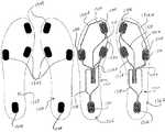
本明細書に記載されるようなセンサシステム12を含む一つのフットウェア製品100は、単独で使用されることもできるし、図24〜26に示す一対の靴100、100'のように、それ自体のセンサシステム12'を有する第二のフットウェア製品100'と組み合わされて使用されることもできる。第二の靴100'のセンサシステム12'は一般に、電子モジュール22'と通信状態にあるポート14'にセンサリード18'によって接続された一つまたは複数のセンサ16'を含む。図24〜26に示す第二の靴100'の第二のセンサシステム12'は、第一の靴100のセンサシステム12と同じ構成を有する。しかし、もう一つの態様において、靴100、100'は、異なる構成を有するセンサシステム12、12'を有することもできる。二つの靴100、100'はいずれも外部装置110との通信のために構成されており、図示される態様において、靴100、100'はそれぞれ、外部装置110との通信のために構成された電子モジュール22、22'を有している。もう一つの態様において、両方の靴100、100'は、同じ電子モジュール22との通信のために構成されたポート14、14'を有することができる。この態様において、少なくとも一つの靴100、100'は、モジュール22との無線通信のために構成されていることができる。図24〜26は、モジュール22、22'の間の通信のための様々なモードを示す。 One
図24は、モジュール22、22'が、互いに通信するように構成され、また、外部装置110との独立した通信のために構成されている「網目」通信モードを示す。図25は、一つのモジュール22'が他方のモジュール22を介して外部装置110と通信する「デイジーチェーン」通信モードを示す。換言するならば、第二のモジュール22'は、信号(データを含むことができる)を第一のモジュール22に送るように構成され、第一のモジュール22は、信号を両方のモジュール22、22'から外部装置110に送るように構成されている。同様に、外部装置は、信号を第一のモジュール22に送り、第一のモジュールがその信号を第二のモジュール22'に送ることにより、第一のモジュール22を介して第二のモジュール22'と通信する。一つの態様において、モジュール22、22'はまた、信号を外部装置110との間で送受信すること以外の目的で互いに通信することができる。図26は、各モジュール22、22'が、外部装置110との独立した通信のために構成され、モジュール22、22'が、互いとの通信のために構成されていない「独立」通信モードを示す。他の態様において、センサシステム12、12'は、別の様式での互いおよび/または外部装置110との通信のために構成されていることもできる。 FIG. 24 shows a “mesh” communication mode in which the
システム12によって収集されるデータのさらに他の用途およびアプリケーションが本発明の範囲にあると考えられ、当業者には認識可能である。 Still other uses and applications of the data collected by the
当業者が本開示を読むことによって理解されるように、本明細書に記載される様々な局面は、方法、データ処理システムまたはコンピュータプログラム製品として具現化されることができる。したがって、これらの局面は、完全なハードウェア態様、完全なソフトウェア態様またはソフトウェア局面とハードウェア局面とを合わせた態様の形態をとることができる。さらには、そのような局面は、記憶媒体の中または上に具現化されたコンピュータ読み取り可能なプログラムコードまたは命令を有する一つまたは複数のコンピュータ読み取り可能な有形記憶媒体または記憶装置によって記憶されるコンピュータプログラム製品の形態をとることができる。ハードディスク、CD-ROM、光学記憶装置、磁気記憶装置および/またはそれらの任意の組み合わせを含む任意の適当なコンピュータ読み取り可能な有形記憶媒体を使用することができる。加えて、本明細書に記載されるような、データまたはイベントを表す様々な無形信号は、金属ワイヤ、光ファイバおよび/または無線送信媒体(たとえば空気および/または空間)のような信号伝導媒体を介して伝わる電磁波の形態で、発信源と宛先との間を伝送されることもできる。 As will be appreciated by one of ordinary skill in the art upon reading this disclosure, the various aspects described herein can be embodied as a method, data processing system, or computer program product. Accordingly, these aspects can take the form of an entirely hardware embodiment, an entirely software embodiment or an embodiment combining software and hardware aspects. Further, such aspects can be stored by one or more computer-readable tangible storage media or storage devices having computer-readable program code or instructions embodied in or on the storage medium. It can take the form of a program product. Any suitable computer readable tangible storage medium may be used including hard disks, CD-ROMs, optical storage devices, magnetic storage devices, and / or any combination thereof. In addition, various intangible signals representing data or events as described herein may be transmitted through signal conducting media such as metal wires, optical fibers and / or wireless transmission media (eg, air and / or space). It can also be transmitted between the source and destination in the form of electromagnetic waves transmitted through.
上記のように、本発明の局面は、コンピュータおよび/またはそのプロセッサによって実行される、コンピュータ実行可能な命令の一般的文脈、たとえばプログラムモジュールとして記述されることができる。一般に、プログラムモジュールは、特定のタスクを実行する、または特定の抽象データタイプを実現するルーチン、プログラム、オブジェクト、コンポーネント、データ構造などを含む。そのようなプログラムモジュールは、上記のようなコンピュータ読み取り可能な有形媒体に含まれることができる。本発明の局面はまた、通信ネットワークを介してリンクされた遠隔処理装置によってタスクが実行される分散コンピューティング環境において実施されることもできる。プログラムモジュールは、メモリ、たとえばモジュール22のメモリ204もしくは外部装置110のメモリ304またはメモリ記憶装置を含むローカルおよび遠隔コンピュータ記憶媒体を含むことができる外部媒体、たとえばゲーム媒体307の中に位置することができる。モジュール22、外部装置110および/または外部媒体は、たとえば特定のアプリケーションにおいていっしょに使用されるための補足的なプログラムモジュールを含むことができることが理解されよう。また、簡素化のために、モジュール22および外部装置110中には一つのプロセッサ202、302および一つのメモリ204、304しか示されず、記載されていないが、プロセッサ202、302およびメモリ204、304は、それぞれ複数のプロセッサおよび/またはメモリを含むことができ、プロセッサおよび/またはメモリのシステムを含むことができることが理解されよう。 As noted above, aspects of the invention can be described as a general context of computer-executable instructions, eg, program modules, executed by a computer and / or its processor. Generally, program modules include routines, programs, objects, components, data structures, etc. that perform particular tasks or implement particular abstract data types. Such a program module can be included in a computer-readable tangible medium as described above. Aspects of the invention may also be practiced in distributed computing environments where tasks are performed by remote processing devices that are linked through a communications network. The program modules may be located in external media, such as game media 307, which may include memory, such as
本明細書に記載されるセンサシステムならびにセンサシステムを組み込んだフットウェア製品、足接触部材、インサートおよび他の構造の様々な態様は、既存の技術に対して恩典および利点を提供する。たとえば、本明細書に記載されるセンサ態様の多くは、センサシステムのための比較的廉価かつ耐久性のオプションを提供して、わずかな追加コストおよび良好な信頼性でセンサシステムをフットウェア製品に組み込むことができるようになっている。結果として、センサシステムが消費者によって使用されることが最終的に望まれるかどうかにかかわらず、価格に大きな影響を加えることなく、一体化センサシステムを含むフットウェアを製造することができる。さらには、カスタマイズされたセンサシステムを有するソールインサートを、そのセンサシステムを使用するように設計されたソフトウェアとともに、ソフトウェアのコストに大きな影響を加えることなく、廉価に製造し、流通させることができる。もう一つの例として、センサシステムは、ゲーム、フィットネス、競技トレーニングおよび向上、コンピュータおよび他の装置の実働制御ならびに本明細書に記載され、当業者によって認識可能である他多くを含む多種多様なアプリケーションのために広範囲の機能性を提供する。一つの態様において、第三者ソフトウェア開発者が、センサシステムからの入力を使用して稼働するように構成された、ゲームおよび他のプログラムを含むソフトウェアを開発することができる。普遍的に読み取り可能なフォーマットでデータを提供するセンサシステムの能力は、センサシステムを使用することができる第三者ソフトウェアおよび他のアプリケーションの範囲を大きく拡大する。さらなる例として、センサシステムを含む様々なソールインサート、たとえばライナ、インソールおよび他の要素は、様々なアプリケーションのためのセンサシステムの交換性およびカスタマイズを可能にする。 Various aspects of the sensor system and footwear products, foot contact members, inserts and other structures incorporating the sensor system described herein provide benefits and advantages over existing technologies. For example, many of the sensor aspects described herein provide a relatively inexpensive and durable option for sensor systems, making sensor systems a footwear product with little additional cost and good reliability. It can be incorporated. As a result, footwear that includes an integrated sensor system can be manufactured without significant impact on price, regardless of whether the sensor system is ultimately desired for use by the consumer. Furthermore, a sole insert having a customized sensor system can be manufactured and distributed at a low cost with software designed to use the sensor system without significantly affecting the cost of the software. As another example, sensor systems may be used in a wide variety of applications, including games, fitness, competitive training and enhancement, production control of computers and other devices, and many others described herein and recognizable by those skilled in the art. Provides a wide range of functionality for. In one aspect, a third party software developer can develop software, including games and other programs, configured to run using input from the sensor system. The ability of a sensor system to provide data in a universally readable format greatly expands the range of third party software and other applications that can use the sensor system. As a further example, various sole inserts including sensor systems, such as liners, insoles and other elements, allow interchangeability and customization of the sensor system for various applications.
いくつかの代替態様および例が本明細書に記載され、例示された。当業者は、個々の態様の特徴ならびにコンポーネントの可能な組み合わせおよび変形を理解するであろう。当業者はさらに、いずれの態様をも本明細書に開示される他の態様と任意の組み合わせで提供することができることを理解するであろう。本発明の真意または中心的特徴を逸脱することなく、本発明を他の具体的な形態で具現化することができることが理解されよう。したがって、本例および態様は、あらゆる点で例示的であり、限定的ではないと考えられなければならず、本発明は、本明細書に記載される詳細には限定されない。本明細書で使用される語「第一の」、「第二の」、「上」、「下」などは、説明目的だけのためのものであり、態様をいかなるようにも限定しない。さらには、本明細書で使用される語「複数」は、1よりも大きい無限数までの任意の数を必要に応じて分離的または接続的にのいずれかを指す。さらには、本明細書に使用される、物品または装置を「提供する」とは、広く、物品を、その物品に対して実施される将来の行為にとって利用可能またはアクセス可能にすることを指し、物品を提供する当事者がその物品を製造、生産または供給したということ、または物品を提供する当事者がその物品の所有権または管理を有することを意味するものではない。したがって、特定の態様が例示され、記載されたが、本発明の真意を有意に逸脱することなく数多くの変形が考えられ、保護の範囲は請求の範囲によってのみ限定される。 Several alternative embodiments and examples have been described and illustrated herein. Those skilled in the art will appreciate the features of the individual aspects and possible combinations and variations of the components. One skilled in the art will further appreciate that any aspect can be provided in any combination with the other aspects disclosed herein. It will be understood that the present invention may be embodied in other specific forms without departing from the spirit or central characteristics of the invention. Accordingly, the examples and aspects are to be considered in all respects as illustrative and not restrictive, and the invention is not limited to the details described herein. The terms “first”, “second”, “upper”, “lower”, etc. as used herein are for illustrative purposes only and do not limit the embodiment in any way. Furthermore, as used herein, the term “plurality” refers to any number up to an infinite number greater than 1 either separately or connected as required. Furthermore, as used herein, “providing” an article or device broadly refers to making the article available or accessible for future actions performed on the article, It does not mean that the party providing the article has manufactured, produced or supplied the article, or that the party providing the article has ownership or control of the article. Thus, while specific embodiments have been illustrated and described, many modifications can be made without significantly departing from the true spirit of the invention, and the scope of protection is limited only by the claims.
本発明のさらなる他の特徴および利点は、添付図面と併せて読まれる以下の詳細な説明から明らかになるであろう。
以下に、本発明の基本的な諸特徴および種々の態様を列挙する。
[001]
足受けチャンバを少なくとも部分的に画定するアッパー部材と、
該アッパー部材と係合したソール構造と、
該ソール構造に接続された複数のセンサおよび該センサと通信状態にある汎用通信ポートを含み、該ポートが、電子モジュールとの通信のために構成されており、各センサが、足によって該センサに加えられた力を検出するように構成されており、かつ該ポートが、各センサによって検出された該力に関するデータを、普遍的に読み取り可能なフォーマットで該電子モジュールに送信するように構成されている、センサシステムと
を含む、フットウェア製品。
[002]
各センサが、活動中に足によって該センサに加えられた前記力の変化を定量的に検出するように構成されている、001記載のフットウェア製品。
[003]
前記ポートが、データをXMLフォーマットで送信するように構成されている、001記載のフットウェア製品。
[004]
少なくとも一つのセンサが前記ソール構造の前部領域に位置し、少なくとも一つのセンサが該ソール構造のヒール領域に位置する、001記載のフットウェア製品。
[005]
第一のセンサが前記ソール構造の第一指節骨区域に位置し、第二のセンサが該ソール構造の第一中足骨頭区域に位置し、第三のセンサが該ソール構造の第五中足骨頭区域に位置し、第四のセンサが該ソール構造のヒール区域に位置する、003記載のフットウェア製品。
[006]
各センサが、第一の電極、第二の電極、および該第一の電極と該第二の電極とを接続している感圧抵抗材料を含む、001記載のフットウェア製品。
[007]
各センサの前記抵抗材料が量子トンネリング複合材を含む、006記載のフットウェア製品。
[008]
各センサの前記抵抗材料がカスタム(custom)導電性フォームを含む、006記載のフットウェア製品。
[009]
各センサが感圧抵抗器を含む、001記載のフットウェア製品。
[010]
前記センサシステムが、前記ポートと通信状態にある前記電子モジュールをさらに含み、該電子モジュールが前記ソール構造中のキャビティ内に収容されている、001記載のフットウェア製品。
[011]
前記電子モジュールが、前記センサによって集められたデータを収集して該データを外部コンピュータ装置に通信するように構成されている、010記載のフットウェア製品。
[012]
前記ポートが、電気接点、USB、FireWire、5ピン、16ピン、他の接触式通信インタフェース、Wi-Fi、Bluetooth、Bluetooth Low Energy、近接場通信、RFID、Zigbeeおよび他の無線通信インタフェースからなる群より選択される少なくとも一つのインタフェースによる通信のために構成されている、001記載のフットウェア製品。
[013]
足受けチャンバを少なくとも部分的に画定するアッパー部材と、
該アッパー部材と係合したソール構造と、
各センサが足によって該センサに加えられた力を検出するように構成されている、該ソール構造に接続された複数の該センサと、
電子モジュールを取り外し可能に受容するように構成されている、該ソール構造中に位置するウェルと、
該電子モジュールが該ウェル中に受容されたときに該センサと該電子モジュールとの間の通信を可能にするように構成されている、該センサを該ウェルに接続している複数のセンサリードと
を含む、フットウェア製品。
[014]
各センサが、活動中に足によって該センサに加えられた前記力の変化を定量的に検出するように構成されている、013記載のフットウェア製品。
[015]
各センサリードが、前記ウェル内でアクセス可能でありかつ前記電子モジュールへの接続のために構成された露出端を有する、013記載のフットウェア製品。
[016]
前記センサリードの前記露出端がマルチピン接続の形式である、015記載のフットウェア製品。
[017]
前記ウェルから前記複数のセンサに接続され、該ウェル内でアクセス可能でありかつ前記電子モジュールへの接続のために構成された露出端を有する、一本のパワーリードをさらに含み、該パワーリードが、該電子モジュールが該ウェル中に受容されたときに該電子モジュールから該センサに電力を提供するように構成されており、前記センサリードおよび該パワーリードの露出端が、該ウェル内でアクセス可能な5ピン接続を形成する、015記載のフットウェア製品。
[018]
前記電子モジュールが前記ウェル中に受容されたときに該電子モジュールから前記複数のセンサに電力を提供するように構成された、該ウェルから該複数のセンサに接続された少なくとも一本のパワーリードをさらに含む、013記載のフットウェア製品。
[019]
前記ウェルから前記複数のセンサすべてに接続された一本のパワーリードを含み、該パワーリードが、該ウェル内でアクセス可能でありかつ前記電子モジュールへの接続のために構成された露出端を有する、017記載のフットウェア製品。
[020]
各センサが感圧抵抗器を含む、013記載のフットウェア製品。
[021]
各センサが、第一の電極、第二の電極、および該第一の電極と該第二の電極とを接続している感圧抵抗材料を含む、013記載のフットウェア製品。
[022]
前記センサシステムが、前記ウェル中に受容された前記電子モジュールをさらに含み、該電子モジュールが、前記センサによって集められたデータを収集して該データを外部コンピュータ装置に通信するように構成されている、013記載のフットウェア製品。
[023]
前記ウェルが、前記センサリードと通信状態にあるポートを含み、前記電子モジュールが、該ポートを介した通信のための補足的インタフェースを含む、022記載のフットウェア製品。
[024]
前記ウェルが、前記センサリードと通信状態にあるポートを含み、該ポートが、前記電子モジュールとの通信のために構成されている、013記載のフットウェア製品。
[025]
前記ウェルが複数の側壁を有し、前記センサリードのすべてが該ウェルの一つの側壁を介して前記ポートに接続されている、024記載のフットウェア製品。
[026]
前記センサリードが一つの場所に集束し、前記ポートのインタフェースへの接続のための統合インタフェースを形成している、024記載のフットウェア製品。
[027]
前記ウェルが複数の側壁を有し、前記センサリードが該側壁の二つまたはそれ以上を介して前記ポートに接続されている、024記載のフットウェア製品。
[028]
前記ウェルが複数の側壁および一つの底壁を有し、前記センサリードが該ウェルの少なくとも一つの側壁および該底壁を介して前記ポートに接続されている、024記載のフットウェア製品。
[029]
前記ウェルが複数の側壁および一つの底壁を有し、前記センサリードのすべてが該ウェルの該底壁を介して前記ポートに接続されている、024記載のフットウェア製品。
[030]
前記ソール構造が、アウトソール部材および、該アウトソール部材と前記足受けチャンバとの間に位置するミッドソール部材をさらに含み、該ミッドソール部材が、少なくとも部分的にその内部に画定された前記ウェルを有する、013記載のフットウェア製品。
[031]
前記ウェルが前記ミッドソール部材の上主面中に開口部を含む、030記載のフットウェア製品。
[032]
前記ソール構造が、前記ミッドソール部材と前記足受けチャンバとの間に位置する足接触部材をさらに含み、該足接触部材が少なくとも部分的に前記ウェルを覆っている、030記載のフットウェア製品。
[033]
前記ソール構造が、前記ミッドソール部材と前記足受けチャンバとの間に位置する足接触部材をさらに含み、前記ウェルが少なくとも部分的に該足接触部材内に収容されている、030記載のフットウェア製品。
[034]
足受けチャンバを少なくとも部分的に画定するアッパー部材と、
該アッパー部材と係合したソール構造と、
各感圧抵抗センサが足によって該センサに加えられた力を検出するように構成された、前記ソール構造の第一指節骨区域に位置する第一のセンサ、該ソール構造の第一中足骨頭区域に位置する第二のセンサ、該ソール構造の第五中足骨頭区域に位置する第三のセンサ、および該ソール構造のヒール区域に位置する第四のセンサを含む、該ソール構造に接続された複数の該感圧抵抗センサと、
電子モジュールとの通信のために構成されている、該センサと通信状態にあるポートと、
該電子モジュールが該ポートと通信状態にあるときに該センサと該電子モジュールとの間の通信を可能にするように構成されている、該センサを該ポートに接続している複数のセンサリードと
を含む、フットウェア製品。
[035]
前記ソール構造が、アウトソール部材および、該アウトソール部材と前記足受けチャンバとの間に位置するミッドソール部材をさらに含み、該ミッドソール部材が、その内部に画定されかつ前記電子モジュールを受容するように構成されたウェルを有する、034記載のフットウェア製品。
[036]
前記ソール構造が、前記ミッドソール部材と前記足受けチャンバとの間に位置する足接触部材をさらに含み、該足接触部材が少なくとも部分的に前記ウェルを覆っている、035記載のフットウェア製品。
[037]
前記ソール構造が、前記ミッドソール部材と前記足受けチャンバとの間に位置する足接触部材をさらに含み、前記ウェルが該足接触部材内に少なくとも部分的に収容されている、035記載のフットウェア製品。
[038]
各センサが、複数のかみ合ったフィンガを有する第一および第二の電極、ならびに、該フィンガの間に配置されて該第一の電極を該第二の電極に接続している感圧抵抗材料を含む、034記載のフットウェア製品。
[039]
前記ソール構造が、前記足受けチャンバの底壁の少なくとも一部分を形成する足接触部材をさらに含み、前記センサおよび前記センサリードが該足接触部材内に埋め込まれている、034記載のフットウェア製品。
[040]
フットウェア製品の足受けチャンバ内での使用のために該足受けチャンバの底壁の少なくとも一部分を形成するように構成されている、足接触部材と、
各センサが足によって該センサに加えられた力を検出するように構成されている、該足接触部材の上主面および下主面の一方に取り付けられた、複数の該センサと、
センサリードが該センサに接続されておりかつ該センサと電子モジュールとの間の通信を可能にするように構成されている、該足接触部材に接続された複数の該センサリードと
を含む、装置。
[041]
前記センサが感圧抵抗センサである、040記載の装置。
[042]
前記センサリードに接続されかつ前記電子モジュールとの通信のために構成されたインタフェースをさらに含む、040記載の装置。
[043]
前記センサおよび前記センサリードが前記足接触部材内に少なくとも部分的に埋め込まれている、040記載の装置。
[044]
前記センサのそれぞれが、前記足接触部材に接続された第一および第二の電極、ならびに該第一および第二の電極と接触状態にある感圧抵抗材料を含む、040記載の装置。
[045]
前記感圧抵抗材料を含むソール部材をさらに含み、該ソール部材が、該感圧抵抗材料が前記第一および第二の電極と接触するように前記足接触部材との面対面接触状態で配置されている、044記載の装置。
[046]
前記ソール部材が、前記フットウェア製品の前記足接触部材とアウトソール部材との間に配置されるように構成されたミッドソール部材を含む、045記載の装置。
[047]
前記ソール部材が、前記足接触部材の上面または下面に配置されるように構成されたライナを含む、045記載の装置。
[048]
前記足接触部材が、中敷き、ブーティー部材、およびインソール部材からなる群より選択される、040記載の装置。
[049]
040記載の装置をフットウェア製品の中に挿入して、足受けチャンバの底壁の少なくとも一部分を形成させる工程を含む、方法。
[050]
前記装置を前記フットウェア製品から取り出す工程、および、
該装置を、
該フットウェア製品の足受けチャンバ内での使用のために、該足受けチャンバの前記底壁の少なくとも一部分を形成するように構成されている、第二の足接触部材と、
該足接触部材に接続されかつ該装置の複数のセンサとは異なる構成で配置された、第二の複数のセンサと
を含む第二の装置と交換する工程
をさらに含む、049記載の方法。
[051]
足受けチャンバを少なくとも部分的に画定するアッパー部材および該アッパー部材と係合したソール構造を含むフットウェア製品と、
該ソール構造に接続された複数のセンサおよび該フットウェア製品内に収容された電子モジュールを含み、該電子モジュールが該センサと通信状態にあり、各センサが、足によって該センサに加えられた力を検出するように構成されている、センサシステムと、
該電子モジュールとの通信のために構成された遠隔外部装置と
を含み、
該電子モジュールが、該センサからデータを受信しかつ該データを該外部装置に送信するように構成されており、該外部装置が、該データのさらなる処理のために構成されている、システム。
[052]
前記外部装置に接続された付属装置をさらに含み、該付属装置が、前記電子モジュールと該外部装置との間の通信を可能にするように構成されており、かつ、該電子モジュールと第二の外部装置との間の通信を可能にするための該第二の外部装置への接続のために構成されている、051記載のシステム。
[053]
前記外部装置用のコントローラをさらに含み、該コントローラが、前記電子モジュールとの通信のために構成されている、051記載のシステム。
[054]
前記コントローラに接続された付属装置をさらに含み、該付属装置が、前記電子モジュールと前記外部装置との間の通信を可能にするように構成されており、かつ、該電子モジュールと第二の外部装置用の第二のコントローラとの間の通信を可能にするための該第二のコントローラへの接続のために構成されている、053記載のシステム。
[055]
各センサが、活動中に足によって該センサに加えられた前記力の変化を定量的に検出するように構成されており、前記データが、該センサの少なくとも一つに加えられた力の定量的計測値を含む、051記載のシステム。
[056]
各センサが、第一の電極、第二の電極、および該第一の電極と該第二の電極とを接続している感圧抵抗材料を含む、051記載のシステム。
[057]
前記データのさらなる処理が、前記外部装置によって実行されるプログラムのための制御入力として該データを使用することを含む、051記載のシステム。
[058]
前記外部装置がゲームシステムであり、前記プログラムがゲームプログラムである、057記載のシステム。
[059]
前記データのさらなる処理が、競技パフォーマンスモニタリングのために該データを使用することを含む、051記載のシステム。
[060]
競技パフォーマンスモニタリングが、スピード、距離、横運動、加速度、ジャンプ高さ、体重移動、足の蹴り出し(foot strike)パターン、バランス、足の回内または回外、走行中の滞空時間測定値、水平方向のカット力(lateral cutting force)、接触時間、圧力中心、体重配分、および衝撃力からなる群より選択される少なくとも一つの測定基準をモニタリングすることを含む、059記載のシステム。
[061]
前記センサシステムが、前記センサに接続されたポートをさらに含み、該ポートが、該センサからのデータを、普遍的に読み取り可能なフォーマットで前記電子モジュールに通信するように構成されている、051記載のシステム。
[062]
足受けチャンバを少なくとも部分的に画定するアッパー部材および該アッパー部材と係合したソール構造を含む、第二のフットウェア製品と、
該第二のフットウェア製品の該ソール構造に接続された第二の複数のセンサおよび該センサと通信状態にある第二の電子モジュールを含み、該第二の複数のセンサそれぞれが、第二の足によって該センサに加えられた力を検出するように構成されている、第二のセンサシステムと
をさらに含み、
該第二の電子モジュールが、該第二の複数のセンサからデータを受信しかつ該データを前記外部装置に送信するように構成されている、051記載のシステム。
[063]
前記電子モジュールおよび前記第二の電子モジュールが互いに通信するように構成されている、062記載のシステム。
[064]
前記第二の電子モジュールが、前記データを前記電子モジュールに送信するように構成されており、該電子モジュールが、該電子モジュールおよび該第二の電子モジュールからのデータを前記外部装置に送信するように構成されている、063記載のシステム。
[065]
前記電子モジュールおよび前記第二の電子モジュールが、互いに独立して前記外部装置と通信するようにさらに構成されている、063記載のシステム。
[066]
前記電子モジュールおよび前記第二の電子モジュールが、互いに独立して前記外部装置と通信するように構成されている、062記載のシステム。
[067]
足受けチャンバを少なくとも部分的に画定するアッパー部材および該アッパー部材と係合したソール構造と、
該ソール構造に接続された複数のセンサおよびフットウェア製品内に収容された電子モジュールを含み、各センサが、足によって該センサに加えられた力を検出するように構成されており、該電子モジュールが、該センサと通信状態にありかつ外部装置との通信のために構成されている、センサシステムと
を含む該フットウェア製品を提供する工程;
該足によって該センサに加えられた該力を示すデータを各センサから該電子モジュールにおいて受信する工程;ならびに
該データをさらに処理するように構成された遠隔外部装置に、該電子モジュールを使用して、該データを送信する工程
を含む、方法。
[068]
前記外部装置のプロセッサを使用して前記データをさらに処理する工程をさらに含む、067記載の方法。
[069]
前記データをさらに処理する工程が、前記外部装置によって実行されるプログラムのための制御入力として該データを使用することを含む、068記載の方法。
[070]
前記外部装置がゲームシステムであり、前記プログラムがゲームプログラムである、069記載の方法。
[071]
足受けチャンバを少なくとも部分的に画定するアッパー部材および該アッパー部材と係合したソール構造および該ソール構造中に収容されたポートと、
該ソール構造に接続された複数のセンサおよび該センサと通信状態にある第一の電子モジュールを含み、該第一の電子モジュールが該ポートに接続され、各センサが、足によって該センサに加えられた力を検出するように構成されており、該第一の電子モジュールが、外部装置との通信のために構成されている、センサシステムと
を含むフットウェア製品を提供する工程;
該第一の電子モジュールを該ポートから取り外す工程;ならびに
第二の電子モジュールを該ポートに接続する工程
を含み、
該第二の電子モジュールが、該第一のモジュールとは異なって作動するように構成されている、方法。
[072]
前記第二のモジュールが第二の外部装置との通信のために構成されている、071記載の方法。
[073]
前記第二のモジュールが、前記第一のモジュールとは異なる様式でデータを集めるように構成されている、071記載の方法。
[074]
前記第二のモジュールが、前記第一のモジュールとは異なる様式でデータを処理するように構成されている、071記載の方法。
[075]
前記第二のモジュールが、前記第一のモジュールとは異なる様式でデータを送信するように構成されている、071記載の方法。
[076]
前記第一のモジュールが第一のアプリケーションにおける使用のために構成されており、前記第二のモジュールが第二のアプリケーションにおける使用のために構成されている、071記載の方法。
[077]
前記第一のアプリケーションおよび前記第二のアプリケーションが、競技パフォーマンスモニタリング、外部装置の制御、およびゲームシステムとの対話からなる群より選択される、076記載の方法。
[078]
前記第一のアプリケーションが競技パフォーマンスモニタリングアプリケーションであり、前記第二のアプリケーションが別の競技パフォーマンスモニタリングアプリケーションである、076記載の方法。
[079]
前記第一のアプリケーションがゲームアプリケーションであり、前記第二のアプリケーションが別のゲームアプリケーションである、076記載の方法。
[080]
前記第二のモジュールが、前記第一のモジュールとは異なる少なくとも一つのハードウェアコンポーネントを含む、071記載の方法。
[081]
足受けチャンバを少なくとも部分的に画定するアッパー部材および該アッパー部材と係合したソール構造を含み、該ソール構造が、その内部に画定されたウェルを有する、フットウェア製品と、
該ソール構造に接続された複数のセンサおよび該センサと通信状態にあるポートを含み、各センサが、足によって該センサに加えられた力を検出するように構成されており、該ポートが、少なくとも一つの電子モジュールとの通信のために構成されている、センサシステムと、
少なくとも一つの電子モジュールとの通信のために構成された外部装置と
を含むシステムを提供する工程;および
第一の電子モジュールが該ソール構造中の該ウェル内に受容されるように、該第一の電子モジュールを該ポートに接続する工程
を含み、
該第一の電子モジュールが、該ポートを介して該センサからデータを受信しかつ該データを該外部装置に送信するように構成されており、該外部装置が、第一のアプリケーションにおける使用のために該データをさらに処理するように構成されている、方法。
[082]
前記第一の電子モジュールと前記ポートとの接続を切って該第一の電子モジュールを前記ウェルから取り出す工程;および
第二の電子モジュールが該ウェル内に受容されるように該第二の電子モジュールを該ポートに接続する工程
をさらに含み、
該第二の電子モジュールが、該ポートを介して前記センサからデータを受信しかつ該データを前記外部装置に送信するように構成されており、該外部装置が、第二のアプリケーションにおける使用のために該データをさらに処理するように構成されている、081記載の方法。
[083]
前記第一のアプリケーションが第一のゲームであり、前記第二のアプリケーションが第二のゲームである、082記載の方法。
[084]
前記第一のアプリケーションが第一の競技パフォーマンスモニタリングアプリケーションであり、前記第二のアプリケーションが第二の競技パフォーマンスモニタリングアプリケーションである、082記載の方法。
[085]
前記第一のアプリケーションが第一のタイプのデータを使用し、前記第二のアプリケーションが第二のタイプのデータを使用する、082記載の方法。
[086]
フットウェア製品に接続された複数の力センサからの力データを電子装置において受信すること、および
該電子装置上で実行されるプログラムのための制御入力として該データを使用することを含む、該電子装置を使用して該データを処理すること
を該電子装置に実行させるように構成されたコンピュータ実行可能な命令を記憶する、コンピュータ読み取り可能な有形記憶媒体。
[087]
前記データが、前記センサおよび前記電子装置と通信状態にある電子モジュールから受信される、086記載のコンピュータ読み取り可能な有形記憶媒体。
[088]
前記命令が、
前記センサとおよび前記電子装置と通信状態にある第二の電子モジュールからの第二の力データを該電子装置において受信すること、ならびに
該電子装置上で実行される第二のプログラムのための制御入力として該第二のデータを使用することを含む、該電子装置を使用して該第二のデータを処理すること
を該電子装置に実行させるようにさらに構成されている、087記載のコンピュータ読み取り可能な有形記憶媒体。
[089]
前記プログラムが第一のゲームプログラムであり、前記第二のプログラムが第二のゲームプログラムである、088記載のコンピュータ読み取り可能な有形記憶媒体。
[090]
前記命令が、
前記電子装置上で実行される第二のプログラムのための制御入力として前記データを使用することを含む、該電子装置を使用して該データを処理すること
を該電子装置に実行させるようにさらに構成されている、086記載のコンピュータ読み取り可能な有形記憶媒体。
[091]
フットウェア製品に接続された複数の力センサからの力データを電子モジュールにおいて受信すること、および
第一のアプリケーションにおける使用のために該データをさらに処理するための外部装置に、該データを送信すること
を該電子モジュールに実行させるように構成されたコンピュータ実行可能な命令を記憶する、コンピュータ読み取り可能な有形記憶媒体。
[092]
前記第一のアプリケーションが、競技パフォーマンスモニタリング、前記外部装置の制御、およびゲームシステムとの対話からなる群より選択される、091記載のコンピュータ読み取り可能な有形記憶媒体。
[093]
前記データが、前記センサの少なくとも一つに加えられた力の定量的計測値を含む、091記載のコンピュータ読み取り可能な有形記憶媒体。
[094]
前記命令が、
前記データを前記外部装置に送信する前に、前記電子モジュールを使用して該データを処理すること
を電子装置に実行させるようにさらに構成されている、091記載のコンピュータ読み取り可能な有形記憶媒体。
[095]
前記命令が、
前記複数の力センサからの第二の力データを前記電子モジュールにおいて受信すること、および
該第二のデータを、第二のアプリケーションにおける使用のために該第二のデータをさらに処理するための第二の外部装置に送信すること
を電子装置に実行させるようにさらに構成されている、091記載のコンピュータ読み取り可能な有形記憶媒体。
[096]
足受けチャンバを少なくとも部分的に画定するアッパー部材と、
面対面接触状態にある少なくとも第一のソール部材および第二のソール部材を含む、該アッパー部材と係合したソール構造と、
感圧抵抗材料が電極対を接続するように、該第一のソール部材に接続された該電極対および該第二のソール部材に接続された該感圧抵抗材料を含み、足によって該センサに加えられた力を検出するように構成されている、該ソール構造に接続されたセンサと、
該センサに接続されておりかつ該センサと電子モジュールとの間の通信を可能にするように構成されている、該第一のソール部材に接続されたセンサリードと
を含む、フットウェア製品。
[097]
前記センサが、活動中に足によって該センサに加えられた力の変化を定量的に検出するように構成されている、096記載のフットウェア製品。
[098]
複数のセンサをさらに含み、各センサが、前記第一のソール部材および前記抵抗材料に接続された電極対を含み、該電極対が該抵抗材料によって接続されている、096記載のフットウェア製品。
[099]
少なくとも一つのセンサが前記ソール構造の前部領域に位置し、少なくとも一つのセンサが該ソール構造のヒール領域に位置する、098記載のフットウェア製品。
[100]
前記第二のソール部材が、前記抵抗材料を含む感圧抵抗要素を含み、該抵抗要素が各センサの前記電極対を接続している、098記載のフットウェア製品。
[101]
前記抵抗材料が量子トンネリング複合材を含む、096記載のフットウェア製品。
[102]
前記抵抗材料がカスタム導電性フォームを含む、096記載のフットウェア製品。
[103]
前記センサシステムが、前記電子モジュールおよび、前記センサリードに接続されかつ該電子モジュールとの通信のために構成されたポートをさらに含み、該電子モジュールが前記ソール構造中のキャビティ内に収容されている、096記載のフットウェア製品。
[104]
前記第一のソール部材が、前記足受けチャンバの一部分を形成する足接触部材を含み、前記第二のソール部材が該足接触部材の下に位置する、096記載のフットウェア製品。
[105]
前記足接触部材が、インソール部材、ブーティー部材、および中敷きからなる群より選択される、104記載のフットウェア製品。
[106]
前記第二のソール部材が、ミッドソール部材および、前記第一のソール部材とミッドソール部材との間に位置するライナからなる群より選択される、104記載のフットウェア製品。
[107]
前記第一のソール部材の下面に前記電極対および前記センサリードがプリントされている、096記載のフットウェア製品。
[108]
前記第二のソール部材全体が前記抵抗材料で構成されている、096記載のフットウェア製品。
[109]
フットウェア製品の足受けチャンバ内での使用のために、該足受けチャンバの底壁の少なくとも一部分を形成するように構成されている、足接触部材と、
各電極対が、感圧抵抗材料によって接続されて複数のセンサの一つを形成するように構成されている、該足接触部材に接続された複数の該電極対と、
センサリードが該電極対に接続されかつ該センサと電子モジュールとの間の通信を可能にするように構成されている、該足接触部材に接続された複数の該センサリードと
を含む、装置。
[110]
少なくとも一つの電極対が前記足接触部材の前部領域に位置し、少なくとも一つの電極対が該足接触部材のヒール領域に位置する、109記載の装置。
[111]
抵抗材料を含む感圧抵抗要素をさらに含み、該抵抗要素が前記電極対それぞれを接続している、109記載の装置。
[112]
前記抵抗材料を含むソール部材をさらに含み、該ソール部材が、該抵抗材料が電極対それぞれを接続するように前記足接触部材と面対面接触状態にある、109記載の装置。
[113]
前記抵抗材料が量子トンネリング複合材を含む、112記載の装置。
[114]
前記抵抗材料がカスタム導電性フォームを含む、112記載の装置。
[115]
前記足接触部材が、インソール部材、ブーティー部材、および中敷きからなる群より選択される、109記載の装置。
[116]
前記足接触部材の下面に前記電極対および前記センサリードがプリントされている、109記載の装置。
[117]
109記載の装置をフットウェア製品の中に挿入して、足受けチャンバの底壁の少なくとも一部分を形成させる工程を含む、方法。
[118]
前記装置を前記フットウェア製品から取り出す工程;ならびに、
該装置を、
該フットウェア製品の前記足受けチャンバ内での使用のために該足受けチャンバの前記底壁の少なくとも一部分を形成するように構成されている、第二の足接触部材と、
各電極対が、感圧抵抗材料によって接続されて第二の複数のセンサの一つを形成するように構成された、該装置の複数の電極対とは異なる構成で配置されかつ該足接触部材に接続された、第二の複数の該電極対と
を含む第二の装置と交換する工程
をさらに含む、117記載の方法。
[119]
足受けチャンバを少なくとも部分的に画定するアッパー部材および該アッパー部材と係合したソール構造を含む、第一のフットウェア製品と、
該第一のフットウェア製品に接続され、複数のセンサおよび該センサと通信状態にある第一の電子モジュールを含み、各センサが、足によって該センサに加えられた力を検出するように構成されている、第一のセンサシステムと、
足受けチャンバを少なくとも部分的に画定するアッパー部材および該アッパー部材と係合したソール構造を含む、第二のフットウェア製品と、
該第二のフットウェア製品に接続され、複数のセンサおよび該センサと通信状態にある第二の電子モジュールを含み、各センサが、足によって該センサに加えられた力を検出するように構成されている、第二のセンサシステムと
を含み、
各電子モジュールが、該センサからデータを受信するように構成されており、かつ、該データを外部装置に通信するようにさらに構成されている、システム。
[120]
前記第一の電子モジュールおよび前記第二の電子モジュールが、互いに通信するようにさらに構成されている、119記載のシステム。
[121]
前記第二の電子モジュールが、前記データを前記第一の電子モジュールに送信するように構成されており、該第一の電子モジュールが、該第一の電子モジュールおよび該第二の電子モジュールからのデータを前記外部装置に送信するように構成されている、120記載のシステム。
[122]
前記第一の電子モジュールおよび前記第二の電子モジュールが、互いに独立して前記外部装置と通信するようにさらに構成されている、120記載のシステム。
[123]
前記第一の電子モジュールおよび前記第二の電子モジュールが、互いに独立して前記外部装置と通信するように構成されている、119記載のシステム。Still other features and advantages of the present invention will become apparent from the following detailed description, read in conjunction with the accompanying drawings.
The basic features and various aspects of the present invention are listed below.
[001]
An upper member that at least partially defines a footrest chamber;
A sole structure engaged with the upper member;
A plurality of sensors connected to the sole structure and a general-purpose communication port in communication with the sensors, wherein the ports are configured for communication with an electronic module, each sensor being connected to the sensor by a foot Configured to detect an applied force, and the port is configured to transmit data regarding the force detected by each sensor to the electronic module in a universally readable format. Footwear products including sensor systems.
[002]
The footwear product of claim 001, wherein each sensor is configured to quantitatively detect a change in the force applied to the sensor by a foot during activity.
[003]
The footwear product of 001, wherein the port is configured to transmit data in XML format.
[004]
102. An article of footwear according to 001, wherein at least one sensor is located in a front region of the sole structure and at least one sensor is located in a heel region of the sole structure.
[005]
A first sensor is located in the first phalange area of the sole structure, a second sensor is located in the first metatarsal head area of the sole structure, and a third sensor is the fifth middle part of the sole structure. The footwear product of 003, located in an ankle head region and a fourth sensor located in a heel region of the sole structure.
[006]
001. An article of footwear according to 001, wherein each sensor includes a first electrode, a second electrode, and a pressure sensitive resistive material connecting the first electrode and the second electrode.
[007]
The footwear product of 006, wherein the resistive material of each sensor comprises a quantum tunneling composite.
[008]
The footwear product of 006, wherein the resistive material of each sensor comprises a custom conductive foam.
[009]
The footwear product of 001, wherein each sensor includes a pressure sensitive resistor.
[010]
102. An article of footwear according to 001, wherein the sensor system further includes the electronic module in communication with the port, the electronic module being housed within a cavity in the sole structure.
[011]
The footwear product of 010, wherein the electronic module is configured to collect data collected by the sensor and communicate the data to an external computing device.
[012]
The port consists of electrical contacts, USB, FireWire, 5 pins, 16 pins, other contact communication interfaces, Wi-Fi, Bluetooth, Bluetooth Low Energy, near field communication, RFID, Zigbee and other wireless communication interfaces 001. A footwear product according to 001, wherein the footwear product is configured for communication over at least one selected interface.
[013]
An upper member that at least partially defines a footrest chamber;
A sole structure engaged with the upper member;
A plurality of the sensors connected to the sole structure, each sensor configured to detect a force applied to the sensors by a foot;
A well located in the sole structure configured to removably receive an electronic module;
A plurality of sensor leads connecting the sensor to the well configured to allow communication between the sensor and the electronic module when the electronic module is received in the well; Including footwear products.
[014]
The footwear product of 013, wherein each sensor is configured to quantitatively detect a change in the force applied to the sensor by a foot during activity.
[015]
The footwear product of 013, wherein each sensor lead has an exposed end that is accessible in the well and configured for connection to the electronic module.
[016]
158. An article of footwear according to 015, wherein the exposed end of the sensor lead is in the form of a multi-pin connection.
[017]
A power lead connected to the plurality of sensors from the well, accessible within the well and having an exposed end configured for connection to the electronic module, the power lead comprising: Configured to provide power from the electronic module to the sensor when the electronic module is received in the well, the sensor lead and the exposed end of the power lead being accessible within the well The footwear product of 015, which forms a simple 5-pin connection.
[018]
At least one power lead connected from the well to the plurality of sensors configured to provide power from the electronic module to the plurality of sensors when the electronic module is received in the well; Furthermore, the footwear product according to 013.
[019]
A power lead connected from the well to all of the plurality of sensors, the power lead being accessible in the well and having an exposed end configured for connection to the electronic module , 017 footwear products.
[020]
The footwear product of 013, wherein each sensor includes a pressure sensitive resistor.
[021]
The footwear product of 013, wherein each sensor includes a first electrode, a second electrode, and a pressure sensitive resistance material connecting the first electrode and the second electrode.
[022]
The sensor system further includes the electronic module received in the well, the electronic module configured to collect data collected by the sensor and communicate the data to an external computing device. , 013 footwear products.
[023]
The footwear product of 022, wherein the well includes a port in communication with the sensor lead and the electronic module includes a supplemental interface for communication via the port.
[024]
The footwear product of 013, wherein the well includes a port in communication with the sensor lead, the port configured for communication with the electronic module.
[025]
249. An article of footwear according to 024, wherein the well has a plurality of sidewalls and all of the sensor leads are connected to the port through one sidewall of the well.
[026]
249. An article of footwear according to 024, wherein the sensor leads are focused in one place to form an integrated interface for connection to an interface of the port.
[027]
249. An article of footwear according to 024, wherein the well has a plurality of sidewalls and the sensor lead is connected to the port through two or more of the sidewalls.
[028]
The footwear product of 024, wherein the well has a plurality of side walls and a bottom wall, and the sensor lead is connected to the port through at least one side wall and the bottom wall of the well.
[029]
249. An article of footwear according to 024, wherein the well has a plurality of side walls and a bottom wall, all of the sensor leads being connected to the port through the bottom wall of the well.
[030]
The sole structure further includes an outsole member and a midsole member positioned between the outsole member and the footrest chamber, wherein the midsole member is at least partially defined therein. The footwear product according to 013, comprising:
[031]
The footwear product of 030, wherein the well includes an opening in an upper major surface of the midsole member.
[032]
The footwear product of claim 030, wherein the sole structure further includes a foot contact member positioned between the midsole member and the foot receiving chamber, the foot contact member at least partially covering the well.
[033]
The footwear of claim 030, wherein the sole structure further includes a foot contact member positioned between the midsole member and the foot receiving chamber, wherein the well is at least partially contained within the foot contact member. Product.
[034]
An upper member that at least partially defines a footrest chamber;
A sole structure engaged with the upper member;
A first sensor located in a first phalanx region of the sole structure, wherein each pressure sensitive resistance sensor is configured to detect a force applied to the sensor by a foot, a first metatarsal of the sole structure Connected to the sole structure, including a second sensor located in the head region, a third sensor located in the fifth metatarsal head region of the sole structure, and a fourth sensor located in the heel region of the sole structure A plurality of the pressure sensitive resistance sensors,
A port configured to communicate with the electronic module in communication with the sensor;
A plurality of sensor leads connecting the sensor to the port configured to allow communication between the sensor and the electronic module when the electronic module is in communication with the port; Including footwear products.
[035]
The sole structure further includes an outsole member and a midsole member positioned between the outsole member and the footrest chamber, the midsole member being defined therein and receiving the electronic module. The footwear product of 034, having a well configured as described above.
[036]
The footwear product of claim 035, wherein the sole structure further includes a foot contact member positioned between the midsole member and the foot receiving chamber, the foot contact member at least partially covering the well.
[037]
The footwear of 035, wherein the sole structure further includes a foot contact member positioned between the midsole member and the foot receiving chamber, wherein the well is at least partially contained within the foot contact member. Product.
[038]
Each sensor includes a first and second electrode having a plurality of interdigitated fingers, and a pressure sensitive resistive material disposed between the fingers and connecting the first electrode to the second electrode Including footwear products as described in 034.
[039]
The footwear product of 034, wherein the sole structure further includes a foot contact member forming at least a portion of a bottom wall of the foot receiving chamber, wherein the sensor and the sensor lead are embedded in the foot contact member.
[040]
A foot contact member configured to form at least a portion of a bottom wall of the footrest chamber for use within the footrest chamber of the footwear product;
A plurality of the sensors attached to one of the upper and lower major surfaces of the foot contact member, each sensor configured to detect a force applied to the sensor by a foot;
A plurality of sensor leads connected to the foot contact member, wherein the sensor leads are connected to the sensor and configured to allow communication between the sensor and the electronic module; .
[041]
The device of 040, wherein the sensor is a pressure sensitive resistance sensor.
[042]
The device of 040, further comprising an interface connected to the sensor lead and configured for communication with the electronic module.
[043]
The device of 040, wherein the sensor and the sensor lead are at least partially embedded in the foot contact member.
[044]
The device of 040, wherein each of the sensors includes a first and second electrode connected to the foot contact member and a pressure sensitive resistance material in contact with the first and second electrode.
[045]
A sole member including the pressure-sensitive resistance material, and the sole member is disposed in face-to-face contact with the foot contact member such that the pressure-sensitive resistance material is in contact with the first and second electrodes. The device according to 044.
[046]
The device of claim 045, wherein the sole member includes a midsole member configured to be disposed between the foot contact member and an outsole member of the footwear product.
[047]
The device of 045, wherein the sole member includes a liner configured to be disposed on an upper surface or a lower surface of the foot contact member.
[048]
The device of 040, wherein the foot contact member is selected from the group consisting of an insole, a bootie member, and an insole member.
[049]
Inserting the device of 040 into a footwear product to form at least a portion of the bottom wall of the footrest chamber.
[050]
Removing the device from the footwear product; and
The device
A second foot contact member configured to form at least a portion of the bottom wall of the footrest chamber for use in the footrest chamber of the footwear product;
The method of 049, further comprising the step of replacing with a second device that includes a second plurality of sensors connected to the foot contact member and disposed in a different configuration than the plurality of sensors of the device.
[051]
An footwear product that includes an upper member that at least partially defines a footrest chamber and a sole structure engaged with the upper member;
A plurality of sensors connected to the sole structure and an electronic module housed in the footwear product, wherein the electronic module is in communication with the sensor, each sensor being applied to the sensor by a foot A sensor system configured to detect
A remote external device configured for communication with the electronic module;
A system, wherein the electronic module is configured to receive data from the sensor and transmit the data to the external device, the external device being configured for further processing of the data.
[052]
An accessory device connected to the external device, the accessory device configured to allow communication between the electronic module and the external device; and the electronic module and a second device The system of 051, wherein the system is configured for connection to the second external device to enable communication with the external device.
[053]
The system of 051, further comprising a controller for the external device, wherein the controller is configured for communication with the electronic module.
[054]
An accessory device connected to the controller, the accessory device configured to allow communication between the electronic module and the external device; and the electronic module and a second external device The system of 053, configured for connection to a second controller to enable communication with the second controller for the device.
[055]
Each sensor is configured to quantitatively detect a change in the force applied to the sensor by a foot during an activity, and the data is quantitative for the force applied to at least one of the sensors. The system of 051, including measurement values.
[056]
The system of 051, wherein each sensor includes a first electrode, a second electrode, and a pressure sensitive resistor material connecting the first electrode and the second electrode.
[057]
The system of 051, wherein the further processing of the data includes using the data as a control input for a program executed by the external device.
[058]
The system according to 057, wherein the external device is a game system and the program is a game program.
[059]
The system of 051, wherein further processing of the data includes using the data for competition performance monitoring.
[060]
Competitive performance monitoring includes speed, distance, lateral movement, acceleration, jump height, weight shift, foot strike pattern, balance, foot pronation or prolapse, flight time measurement while running, horizontal The system of 059, comprising monitoring at least one metric selected from the group consisting of lateral cutting force, contact time, pressure center, weight distribution, and impact force.
[061]
The 051 sensor system further comprises a port connected to the sensor, the port configured to communicate data from the sensor to the electronic module in a universally readable format. System.
[062]
A second footwear product comprising an upper member that at least partially defines a footrest chamber and a sole structure engaged with the upper member;
A second plurality of sensors connected to the sole structure of the second footwear product and a second electronic module in communication with the sensors, each of the second plurality of sensors by a second foot A second sensor system configured to detect a force applied to the sensor;
The system of 051, wherein the second electronic module is configured to receive data from the second plurality of sensors and send the data to the external device.
[063]
The system of 062, wherein the electronic module and the second electronic module are configured to communicate with each other.
[064]
The second electronic module is configured to transmit the data to the electronic module, and the electronic module transmits data from the electronic module and the second electronic module to the external device. The system of 063, configured in
[065]
The system of 063, wherein the electronic module and the second electronic module are further configured to communicate with the external device independently of each other.
[066]
The system of 062, wherein the electronic module and the second electronic module are configured to communicate with the external device independently of each other.
[067]
An upper member at least partially defining a footrest chamber and a sole structure engaged with the upper member;
A plurality of sensors connected to the sole structure and an electronic module housed in a footwear product, each sensor configured to detect a force applied to the sensor by a foot, the electronic module Providing the footwear product comprising a sensor system in communication with the sensor and configured for communication with an external device;
Receiving data indicative of the force applied to the sensor by the foot at each electronic module from each sensor; and using the electronic module to a remote external device configured to further process the data Transmitting the data.
[068]
The method of 067, further comprising the step of further processing the data using a processor of the external device.
[069]
The method of 068, wherein the further processing of the data includes using the data as a control input for a program executed by the external device.
[070]
The method of 069, wherein the external device is a game system and the program is a game program.
[071]
An upper member that at least partially defines a footrest chamber, a sole structure engaged with the upper member, and a port housed in the sole structure;
A plurality of sensors connected to the sole structure and a first electronic module in communication with the sensors, the first electronic module being connected to the port, each sensor being added to the sensor by a foot Providing a footwear product comprising a sensor system, wherein the first electronic module is configured to detect an external force, and wherein the first electronic module is configured for communication with an external device;
Removing the first electronic module from the port; and connecting a second electronic module to the port;
The method wherein the second electronic module is configured to operate differently than the first module.
[072]
The method of 071, wherein the second module is configured for communication with a second external device.
[073]
The method of 071, wherein the second module is configured to collect data in a different manner than the first module.
[074]
The method of 071, wherein the second module is configured to process data in a different manner than the first module.
[075]
The method of 071, wherein the second module is configured to transmit data in a different manner than the first module.
[076]
The method of 071, wherein the first module is configured for use in a first application and the second module is configured for use in a second application.
[077]
The method of 076, wherein the first application and the second application are selected from the group consisting of competition performance monitoring, control of external devices, and interaction with a gaming system.
[078]
The method of 076, wherein the first application is a competition performance monitoring application and the second application is another competition performance monitoring application.
[079]
The method of 076, wherein the first application is a game application and the second application is another game application.
[080]
The method of 071, wherein the second module includes at least one hardware component different from the first module.
[081]
An footwear product comprising an upper member at least partially defining a footrest chamber and a sole structure engaged with the upper member, the sole structure having a well defined therein;
A plurality of sensors connected to the sole structure and a port in communication with the sensors, each sensor configured to detect a force applied to the sensor by a foot, the port comprising at least A sensor system configured for communication with one electronic module;
Providing a system that includes an external device configured for communication with at least one electronic module; and wherein the first electronic module is received within the well in the sole structure Connecting the electronic module to the port,
The first electronic module is configured to receive data from the sensor and transmit the data to the external device via the port, the external device being used for a first application; A method configured to further process the data.
[082]
Disconnecting the first electronic module and the port and removing the first electronic module from the well; and the second electronic module such that a second electronic module is received in the well Further connecting the port to the port,
The second electronic module is configured to receive data from the sensor via the port and send the data to the external device, the external device being used for a second application The method of 081, further configured to further process the data.
[083]
The method of 082, wherein the first application is a first game and the second application is a second game.
[084]
The method of 082, wherein the first application is a first competition performance monitoring application and the second application is a second competition performance monitoring application.
[085]
The method of 082, wherein the first application uses a first type of data and the second application uses a second type of data.
[086]
Receiving at the electronic device force data from a plurality of force sensors connected to the footwear product, and using the data as a control input for a program executed on the electronic device. A computer-readable tangible storage medium storing computer-executable instructions configured to cause the electronic device to perform processing of the data using the device.
[087]
The computer readable tangible storage medium of 086, wherein the data is received from an electronic module in communication with the sensor and the electronic device.
[088]
The instruction is
Receiving at the electronic device second force data from the sensor and a second electronic module in communication with the electronic device, and control for a second program executed on the electronic device The computer-readable device of 087, further configured to cause the electronic device to perform processing the second data using the electronic device, including using the second data as input. Possible tangible storage medium.
[089]
The computer-readable tangible storage medium according to 088, wherein the program is a first game program and the second program is a second game program.
[090]
The instruction is
Further causing the electronic device to perform processing of the data using the electronic device, including using the data as a control input for a second program executed on the electronic device. The computer-readable tangible storage medium described in 086.
[091]
Receiving force data from a plurality of force sensors connected to the footwear product at the electronic module, and transmitting the data to an external device for further processing for use in the first application A computer-readable tangible storage medium storing computer-executable instructions configured to cause the electronic module to execute.
[092]
The computer-readable tangible storage medium of 091, wherein the first application is selected from the group consisting of competition performance monitoring, control of the external device, and interaction with a game system.
[093]
The computer readable tangible storage medium of 091, wherein the data includes a quantitative measurement of force applied to at least one of the sensors.
[094]
The instruction is
The computer readable tangible storage medium of 091, further configured to cause an electronic device to perform processing of the data using the electronic module before transmitting the data to the external device.
[095]
The instruction is
Receiving second force data from the plurality of force sensors at the electronic module; and second processing the second data for further processing for use in a second application. The computer-readable tangible storage medium of 091, further configured to cause an electronic device to perform transmission to a second external device.
[096]
An upper member that at least partially defines a footrest chamber;
A sole structure engaged with the upper member, comprising at least a first sole member and a second sole member in face-to-face contact;
The pressure sensitive resistance material includes the electrode pair connected to the first sole member and the pressure sensitive resistance material connected to the second sole member such that the pressure sensitive resistance material connects the electrode pair to the sensor by a foot. A sensor connected to the sole structure configured to detect an applied force;
A footwear product comprising a sensor lead connected to the first sole member connected to the sensor and configured to allow communication between the sensor and the electronic module.
[097]
The footwear product of 096, wherein the sensor is configured to quantitatively detect a change in force applied to the sensor by a foot during activity.
[098]
The footwear product of 096, further comprising a plurality of sensors, each sensor including an electrode pair connected to the first sole member and the resistive material, wherein the electrode pair is connected by the resistive material.
[099]
The footwear product of claim 098, wherein at least one sensor is located in a front region of the sole structure and at least one sensor is located in a heel region of the sole structure.
[100]
The footwear product of claim 098, wherein the second sole member includes a pressure-sensitive resistance element including the resistance material, and the resistance element connects the electrode pair of each sensor.
[101]
The footwear product of 096, wherein the resistive material comprises a quantum tunneling composite.
[102]
The footwear product of 096, wherein the resistive material comprises custom conductive foam.
[103]
The sensor system further includes the electronic module and a port connected to the sensor lead and configured for communication with the electronic module, the electronic module being housed in a cavity in the sole structure. , 096 listed footwear products.
[104]
The footwear product of claim 096, wherein the first sole member includes a foot contact member that forms a portion of the foot receiving chamber, and wherein the second sole member is located below the foot contact member.
[105]
105. An article of footwear according to 104, wherein the foot contact member is selected from the group consisting of an insole member, a bootie member, and an insole.
[106]
105. An article of footwear according to 104, wherein the second sole member is selected from the group consisting of a midsole member and a liner positioned between the first sole member and the midsole member.
[107]
The footwear product according to 096, wherein the electrode pair and the sensor lead are printed on a lower surface of the first sole member.
[108]
The footwear product according to 096, wherein the entire second sole member is made of the resistance material.
[109]
A foot contact member configured to form at least a portion of a bottom wall of the footrest chamber for use in a footrest chamber of a footwear product;
A plurality of electrode pairs connected to the foot contact member, each electrode pair configured to be connected by a pressure sensitive resistor material to form one of a plurality of sensors;
A plurality of sensor leads connected to the foot contact member, wherein a sensor lead is connected to the electrode pair and configured to allow communication between the sensor and the electronic module.
[110]
110. The apparatus according to 109, wherein at least one electrode pair is located in a front region of the foot contact member and at least one electrode pair is located in a heel region of the foot contact member.
[111]
110. The apparatus according to 109, further comprising a pressure sensitive resistive element comprising a resistive material, the resistive element connecting each of the electrode pairs.
[112]
110. The apparatus of 109, further comprising a sole member comprising the resistive material, wherein the sole member is in face-to-face contact with the foot contact member such that the resistive material connects each pair of electrodes.
[113]
113. The apparatus according to 112, wherein the resistive material comprises a quantum tunneling composite.
[114]
113. The apparatus according to 112, wherein the resistive material comprises a custom conductive foam.
[115]
110. The apparatus according to 109, wherein the foot contact member is selected from the group consisting of an insole member, a bootie member, and an insole.
[116]
110. The apparatus according to 109, wherein the electrode pair and the sensor lead are printed on a lower surface of the foot contact member.
[117]
109. A method comprising inserting the apparatus of 109 into a footwear product to form at least a portion of a bottom wall of a footrest chamber.
[118]
Removing the device from the footwear product; and
The device
A second foot contact member configured to form at least a portion of the bottom wall of the footrest chamber for use in the footwear chamber of the footwear product;
The foot contact member is arranged in a different configuration from the plurality of electrode pairs of the device, each electrode pair configured to be connected by a pressure sensitive resistor material to form one of the second plurality of sensors. 118. The method according to 117, further comprising the step of replacing with a second device connected to the second device comprising a second plurality of the electrode pairs.
[119]
A first footwear product comprising an upper member that at least partially defines a footrest chamber and a sole structure engaged with the upper member;
Connected to the first footwear product and comprising a plurality of sensors and a first electronic module in communication with the sensors, each sensor configured to detect a force applied to the sensor by a foot The first sensor system,
A second footwear product comprising an upper member that at least partially defines a footrest chamber and a sole structure engaged with the upper member;
Connected to the second footwear product and comprising a plurality of sensors and a second electronic module in communication with the sensors, each sensor configured to detect a force applied to the sensor by a foot A second sensor system,
A system wherein each electronic module is configured to receive data from the sensor and is further configured to communicate the data to an external device.
[120]
120. The system of 119, wherein the first electronic module and the second electronic module are further configured to communicate with each other.
[121]
The second electronic module is configured to transmit the data to the first electronic module, the first electronic module from the first electronic module and the second electronic module; 121. The system according to 120, wherein the system is configured to send data to the external device.
[122]
121. The system of 120, wherein the first electronic module and the second electronic module are further configured to communicate with the external device independently of each other.
[one two Three]
119. The system of claim 119, wherein the first electronic module and the second electronic module are configured to communicate with the external device independently of each other.
Claims (123)
Translated fromJapanese該アッパー部材と係合したソール構造と、
該ソール構造に接続された複数のセンサおよび該センサと通信状態にある汎用通信ポートを含み、該ポートが、電子モジュールとの通信のために構成されており、各センサが、足によって該センサに加えられた力を検出するように構成されており、かつ該ポートが、各センサによって検出された該力に関するデータを、普遍的に読み取り可能なフォーマットで該電子モジュールに送信するように構成されている、センサシステムと
を含む、フットウェア製品。An upper member that at least partially defines a footrest chamber;
A sole structure engaged with the upper member;
A plurality of sensors connected to the sole structure and a general-purpose communication port in communication with the sensors, wherein the ports are configured for communication with an electronic module, each sensor being connected to the sensor by a foot Configured to detect an applied force, and the port is configured to transmit data regarding the force detected by each sensor to the electronic module in a universally readable format. Footwear products including sensor systems.
該アッパー部材と係合したソール構造と、
各センサが足によって該センサに加えられた力を検出するように構成されている、該ソール構造に接続された複数の該センサと、
電子モジュールを取り外し可能に受容するように構成されている、該ソール構造中に位置するウェルと、
該電子モジュールが該ウェル中に受容されたときに該センサと該電子モジュールとの間の通信を可能にするように構成されている、該センサを該ウェルに接続している複数のセンサリードと
を含む、フットウェア製品。An upper member that at least partially defines a footrest chamber;
A sole structure engaged with the upper member;
A plurality of the sensors connected to the sole structure, each sensor configured to detect a force applied to the sensors by a foot;
A well located in the sole structure configured to removably receive an electronic module;
A plurality of sensor leads connecting the sensor to the well configured to allow communication between the sensor and the electronic module when the electronic module is received in the well; Including footwear products.
該アッパー部材と係合したソール構造と、
各感圧抵抗センサが足によって該センサに加えられた力を検出するように構成された、前記ソール構造の第一指節骨区域に位置する第一のセンサ、該ソール構造の第一中足骨頭区域に位置する第二のセンサ、該ソール構造の第五中足骨頭区域に位置する第三のセンサ、および該ソール構造のヒール区域に位置する第四のセンサを含む、該ソール構造に接続された複数の該感圧抵抗センサと、
電子モジュールとの通信のために構成されている、該センサと通信状態にあるポートと、
該電子モジュールが該ポートと通信状態にあるときに該センサと該電子モジュールとの間の通信を可能にするように構成されている、該センサを該ポートに接続している複数のセンサリードと
を含む、フットウェア製品。An upper member that at least partially defines a footrest chamber;
A sole structure engaged with the upper member;
A first sensor located in a first phalanx region of the sole structure, wherein each pressure sensitive resistance sensor is configured to detect a force applied to the sensor by a foot, a first metatarsal of the sole structure Connected to the sole structure, including a second sensor located in the head region, a third sensor located in the fifth metatarsal head region of the sole structure, and a fourth sensor located in the heel region of the sole structure A plurality of the pressure sensitive resistance sensors,
A port configured to communicate with the electronic module in communication with the sensor;
A plurality of sensor leads connecting the sensor to the port configured to allow communication between the sensor and the electronic module when the electronic module is in communication with the port; Including footwear products.
各センサが足によって該センサに加えられた力を検出するように構成されている、該足接触部材の上主面および下主面の一方に取り付けられた、複数の該センサと、
センサリードが該センサに接続されておりかつ該センサと電子モジュールとの間の通信を可能にするように構成されている、該足接触部材に接続された複数の該センサリードと
を含む、装置。A foot contact member configured to form at least a portion of a bottom wall of the footrest chamber for use within the footrest chamber of the footwear product;
A plurality of the sensors attached to one of the upper and lower major surfaces of the foot contact member, each sensor configured to detect a force applied to the sensor by a foot;
A plurality of sensor leads connected to the foot contact member, wherein the sensor leads are connected to the sensor and configured to allow communication between the sensor and the electronic module; .
該装置を、
該フットウェア製品の足受けチャンバ内での使用のために、該足受けチャンバの前記底壁の少なくとも一部分を形成するように構成されている、第二の足接触部材と、
該足接触部材に接続されかつ該装置の複数のセンサとは異なる構成で配置された、第二の複数のセンサと
を含む第二の装置と交換する工程
をさらに含む、請求項49記載の方法。Removing the device from the footwear product; and
The device
A second foot contact member configured to form at least a portion of the bottom wall of the footrest chamber for use in the footrest chamber of the footwear product;
50. The method of claim 49, further comprising replacing a second device including a second plurality of sensors connected to the foot contact member and arranged in a different configuration than the plurality of sensors of the device. .
該ソール構造に接続された複数のセンサおよび該フットウェア製品内に収容された電子モジュールを含み、該電子モジュールが該センサと通信状態にあり、各センサが、足によって該センサに加えられた力を検出するように構成されている、センサシステムと、
該電子モジュールとの通信のために構成された遠隔外部装置と
を含み、
該電子モジュールが、該センサからデータを受信しかつ該データを該外部装置に送信するように構成されており、該外部装置が、該データのさらなる処理のために構成されている、システム。An footwear product that includes an upper member that at least partially defines a footrest chamber and a sole structure engaged with the upper member;
A plurality of sensors connected to the sole structure and an electronic module housed in the footwear product, wherein the electronic module is in communication with the sensor, each sensor being applied to the sensor by a foot A sensor system configured to detect
A remote external device configured for communication with the electronic module;
A system, wherein the electronic module is configured to receive data from the sensor and transmit the data to the external device, the external device being configured for further processing of the data.
該第二のフットウェア製品の該ソール構造に接続された第二の複数のセンサおよび該センサと通信状態にある第二の電子モジュールを含み、該第二の複数のセンサそれぞれが、第二の足によって該センサに加えられた力を検出するように構成されている、第二のセンサシステムと
をさらに含み、
該第二の電子モジュールが、該第二の複数のセンサからデータを受信しかつ該データを前記外部装置に送信するように構成されている、請求項51記載のシステム。A second footwear product comprising an upper member that at least partially defines a footrest chamber and a sole structure engaged with the upper member;
A second plurality of sensors connected to the sole structure of the second footwear product and a second electronic module in communication with the sensors, each of the second plurality of sensors by a second foot A second sensor system configured to detect a force applied to the sensor;
52. The system of claim 51, wherein the second electronic module is configured to receive data from the second plurality of sensors and transmit the data to the external device.
該ソール構造に接続された複数のセンサおよびフットウェア製品内に収容された電子モジュールを含み、各センサが、足によって該センサに加えられた力を検出するように構成されており、該電子モジュールが、該センサと通信状態にありかつ外部装置との通信のために構成されている、センサシステムと
を含む該フットウェア製品を提供する工程;
該足によって該センサに加えられた該力を示すデータを各センサから該電子モジュールにおいて受信する工程;ならびに
該データをさらに処理するように構成された遠隔外部装置に、該電子モジュールを使用して、該データを送信する工程
を含む、方法。An upper member at least partially defining a footrest chamber and a sole structure engaged with the upper member;
A plurality of sensors connected to the sole structure and an electronic module housed in a footwear product, each sensor configured to detect a force applied to the sensor by a foot, the electronic module Providing the footwear product comprising a sensor system in communication with the sensor and configured for communication with an external device;
Receiving data indicative of the force applied to the sensor by the foot at each electronic module from each sensor; and using the electronic module to a remote external device configured to further process the data Transmitting the data.
該ソール構造に接続された複数のセンサおよび該センサと通信状態にある第一の電子モジュールを含み、該第一の電子モジュールが該ポートに接続され、各センサが、足によって該センサに加えられた力を検出するように構成されており、該第一の電子モジュールが、外部装置との通信のために構成されている、センサシステムと
を含むフットウェア製品を提供する工程;
該第一の電子モジュールを該ポートから取り外す工程;ならびに
第二の電子モジュールを該ポートに接続する工程
を含み、
該第二の電子モジュールが、該第一のモジュールとは異なって作動するように構成されている、方法。An upper member that at least partially defines a footrest chamber, a sole structure engaged with the upper member, and a port housed in the sole structure;
A plurality of sensors connected to the sole structure and a first electronic module in communication with the sensors, the first electronic module being connected to the port, each sensor being added to the sensor by a foot Providing a footwear product comprising a sensor system, wherein the first electronic module is configured to detect an external force, and wherein the first electronic module is configured for communication with an external device;
Removing the first electronic module from the port; and connecting a second electronic module to the port;
The method wherein the second electronic module is configured to operate differently than the first module.
該ソール構造に接続された複数のセンサおよび該センサと通信状態にあるポートを含み、各センサが、足によって該センサに加えられた力を検出するように構成されており、該ポートが、少なくとも一つの電子モジュールとの通信のために構成されている、センサシステムと、
少なくとも一つの電子モジュールとの通信のために構成された外部装置と
を含むシステムを提供する工程;および
第一の電子モジュールが該ソール構造中の該ウェル内に受容されるように、該第一の電子モジュールを該ポートに接続する工程
を含み、
該第一の電子モジュールが、該ポートを介して該センサからデータを受信しかつ該データを該外部装置に送信するように構成されており、該外部装置が、第一のアプリケーションにおける使用のために該データをさらに処理するように構成されている、方法。An footwear product comprising an upper member at least partially defining a footrest chamber and a sole structure engaged with the upper member, the sole structure having a well defined therein;
A plurality of sensors connected to the sole structure and a port in communication with the sensors, each sensor configured to detect a force applied to the sensor by a foot, the port comprising at least A sensor system configured for communication with one electronic module;
Providing a system that includes an external device configured for communication with at least one electronic module; and wherein the first electronic module is received within the well in the sole structure Connecting the electronic module to the port,
The first electronic module is configured to receive data from the sensor and transmit the data to the external device via the port, the external device being used for a first application; A method configured to further process the data.
第二の電子モジュールが該ウェル内に受容されるように該第二の電子モジュールを該ポートに接続する工程
をさらに含み、
該第二の電子モジュールが、該ポートを介して前記センサからデータを受信しかつ該データを前記外部装置に送信するように構成されており、該外部装置が、第二のアプリケーションにおける使用のために該データをさらに処理するように構成されている、請求項81記載の方法。Disconnecting the first electronic module and the port and removing the first electronic module from the well; and the second electronic module such that a second electronic module is received in the well Further connecting the port to the port,
The second electronic module is configured to receive data from the sensor via the port and send the data to the external device, the external device being used for a second application 84. The method of claim 81, further configured to further process the data.
該電子装置上で実行されるプログラムのための制御入力として該データを使用することを含む、該電子装置を使用して該データを処理すること
を該電子装置に実行させるように構成されたコンピュータ実行可能な命令を記憶する、コンピュータ読み取り可能な有形記憶媒体。Receiving at the electronic device force data from a plurality of force sensors connected to the footwear product, and using the data as a control input for a program executed on the electronic device. A computer-readable tangible storage medium storing computer-executable instructions configured to cause the electronic device to perform processing of the data using the device.
前記センサとおよび前記電子装置と通信状態にある第二の電子モジュールからの第二の力データを該電子装置において受信すること、ならびに
該電子装置上で実行される第二のプログラムのための制御入力として該第二のデータを使用することを含む、該電子装置を使用して該第二のデータを処理すること
を該電子装置に実行させるようにさらに構成されている、請求項87記載のコンピュータ読み取り可能な有形記憶媒体。The instruction is
Receiving at the electronic device second force data from the sensor and a second electronic module in communication with the electronic device, and control for a second program executed on the electronic device 90. The device of claim 87, further configured to cause the electronic device to process the second data using the electronic device, including using the second data as input. Computer-readable tangible storage medium.
前記電子装置上で実行される第二のプログラムのための制御入力として前記データを使用することを含む、該電子装置を使用して該データを処理すること
を該電子装置に実行させるようにさらに構成されている、請求項86記載のコンピュータ読み取り可能な有形記憶媒体。The instruction is
Further causing the electronic device to perform processing of the data using the electronic device, including using the data as a control input for a second program executed on the electronic device. 90. A computer readable tangible storage medium as defined in claim 86, wherein
第一のアプリケーションにおける使用のために該データをさらに処理するための外部装置に、該データを送信すること
を該電子モジュールに実行させるように構成されたコンピュータ実行可能な命令を記憶する、コンピュータ読み取り可能な有形記憶媒体。Receiving force data from a plurality of force sensors connected to the footwear product at the electronic module, and transmitting the data to an external device for further processing for use in the first application A computer-readable tangible storage medium storing computer-executable instructions configured to cause the electronic module to execute.
前記データを前記外部装置に送信する前に、前記電子モジュールを使用して該データを処理すること
を電子装置に実行させるようにさらに構成されている、請求項91記載のコンピュータ読み取り可能な有形記憶媒体。The instruction is
92. The computer readable tangible storage of claim 91, further configured to cause an electronic device to perform processing of the data using the electronic module prior to transmitting the data to the external device. Medium.
前記複数の力センサからの第二の力データを前記電子モジュールにおいて受信すること、および
該第二のデータを、第二のアプリケーションにおける使用のために該第二のデータをさらに処理するための第二の外部装置に送信すること
を電子装置に実行させるようにさらに構成されている、請求項91記載のコンピュータ読み取り可能な有形記憶媒体。The instruction is
Receiving second force data from the plurality of force sensors at the electronic module; and second processing the second data for further processing for use in a second application. 92. The computer readable tangible storage medium of claim 91, further configured to cause an electronic device to perform transmission to a second external device.
面対面接触状態にある少なくとも第一のソール部材および第二のソール部材を含む、該アッパー部材と係合したソール構造と、
感圧抵抗材料が電極対を接続するように、該第一のソール部材に接続された該電極対および該第二のソール部材に接続された該感圧抵抗材料を含み、足によって該センサに加えられた力を検出するように構成されている、該ソール構造に接続されたセンサと、
該センサに接続されておりかつ該センサと電子モジュールとの間の通信を可能にするように構成されている、該第一のソール部材に接続されたセンサリードと
を含む、フットウェア製品。An upper member that at least partially defines a footrest chamber;
A sole structure engaged with the upper member, comprising at least a first sole member and a second sole member in face-to-face contact;
The pressure sensitive resistance material includes the electrode pair connected to the first sole member and the pressure sensitive resistance material connected to the second sole member such that the pressure sensitive resistance material connects the electrode pair to the sensor by a foot. A sensor connected to the sole structure configured to detect an applied force;
A footwear product comprising a sensor lead connected to the first sole member connected to the sensor and configured to allow communication between the sensor and the electronic module.
各電極対が、感圧抵抗材料によって接続されて複数のセンサの一つを形成するように構成されている、該足接触部材に接続された複数の該電極対と、
センサリードが該電極対に接続されかつ該センサと電子モジュールとの間の通信を可能にするように構成されている、該足接触部材に接続された複数の該センサリードと
を含む、装置。A foot contact member configured to form at least a portion of a bottom wall of the footrest chamber for use in a footrest chamber of a footwear product;
A plurality of electrode pairs connected to the foot contact member, each electrode pair configured to be connected by a pressure sensitive resistor material to form one of a plurality of sensors;
A plurality of sensor leads connected to the foot contact member, wherein a sensor lead is connected to the electrode pair and configured to allow communication between the sensor and the electronic module.
該装置を、
該フットウェア製品の前記足受けチャンバ内での使用のために該足受けチャンバの前記底壁の少なくとも一部分を形成するように構成されている、第二の足接触部材と、
各電極対が、感圧抵抗材料によって接続されて第二の複数のセンサの一つを形成するように構成された、該装置の複数の電極対とは異なる構成で配置されかつ該足接触部材に接続された、第二の複数の該電極対と
を含む第二の装置と交換する工程
をさらに含む、請求項117記載の方法。Removing the device from the footwear product; and
The device
A second foot contact member configured to form at least a portion of the bottom wall of the footrest chamber for use in the footwear chamber of the footwear product;
The foot contact member is arranged in a different configuration from the plurality of electrode pairs of the device, each electrode pair configured to be connected by a pressure sensitive resistor material to form one of the second plurality of sensors. 118. The method of claim 117, further comprising the step of replacing with a second device that includes a second plurality of the electrode pairs connected to the device.
該第一のフットウェア製品に接続され、複数のセンサおよび該センサと通信状態にある第一の電子モジュールを含み、各センサが、足によって該センサに加えられた力を検出するように構成されている、第一のセンサシステムと、
足受けチャンバを少なくとも部分的に画定するアッパー部材および該アッパー部材と係合したソール構造を含む、第二のフットウェア製品と、
該第二のフットウェア製品に接続され、複数のセンサおよび該センサと通信状態にある第二の電子モジュールを含み、各センサが、足によって該センサに加えられた力を検出するように構成されている、第二のセンサシステムと
を含み、
各電子モジュールが、該センサからデータを受信するように構成されており、かつ、該データを外部装置に通信するようにさらに構成されている、システム。A first footwear product comprising an upper member that at least partially defines a footrest chamber and a sole structure engaged with the upper member;
Connected to the first footwear product and comprising a plurality of sensors and a first electronic module in communication with the sensors, each sensor configured to detect a force applied to the sensor by a foot The first sensor system,
A second footwear product comprising an upper member that at least partially defines a footrest chamber and a sole structure engaged with the upper member;
Connected to the second footwear product and comprising a plurality of sensors and a second electronic module in communication with the sensors, each sensor configured to detect a force applied to the sensor by a foot A second sensor system,
A system wherein each electronic module is configured to receive data from the sensor and is further configured to communicate the data to an external device.
Priority Applications (1)
| Application Number | Priority Date | Filing Date | Title |
|---|---|---|---|
| JP2020038360AJP6893266B2 (en) | 2008-06-13 | 2020-03-06 | Footwear with sensor system |
Applications Claiming Priority (4)
| Application Number | Priority Date | Filing Date | Title |
|---|---|---|---|
| US6142708P | 2008-06-13 | 2008-06-13 | |
| US61/061,427 | 2008-06-13 | ||
| US13804808P | 2008-12-16 | 2008-12-16 | |
| US61/138,048 | 2008-12-16 |
Related Parent Applications (1)
| Application Number | Title | Priority Date | Filing Date |
|---|---|---|---|
| JP2016084261ADivisionJP6290292B2 (en) | 2008-06-13 | 2016-04-20 | Footwear with sensor system |
Related Child Applications (1)
| Application Number | Title | Priority Date | Filing Date |
|---|---|---|---|
| JP2020038360ADivisionJP6893266B2 (en) | 2008-06-13 | 2020-03-06 | Footwear with sensor system |
Publications (2)
| Publication Number | Publication Date |
|---|---|
| JP2018122098Atrue JP2018122098A (en) | 2018-08-09 |
| JP6674487B2 JP6674487B2 (en) | 2020-04-01 |
Family
ID=41021150
Family Applications (5)
| Application Number | Title | Priority Date | Filing Date |
|---|---|---|---|
| JP2011513731AActiveJP5925490B2 (en) | 2008-06-13 | 2009-06-12 | Footwear with sensor system |
| JP2016084261AActiveJP6290292B2 (en) | 2008-06-13 | 2016-04-20 | Footwear with sensor system |
| JP2018020022AActiveJP6674487B2 (en) | 2008-06-13 | 2018-02-07 | Footwear with sensor system |
| JP2020038360AActiveJP6893266B2 (en) | 2008-06-13 | 2020-03-06 | Footwear with sensor system |
| JP2021091019AActiveJP7104218B2 (en) | 2008-06-13 | 2021-05-31 | Footwear with sensor system |
Family Applications Before (2)
| Application Number | Title | Priority Date | Filing Date |
|---|---|---|---|
| JP2011513731AActiveJP5925490B2 (en) | 2008-06-13 | 2009-06-12 | Footwear with sensor system |
| JP2016084261AActiveJP6290292B2 (en) | 2008-06-13 | 2016-04-20 | Footwear with sensor system |
Family Applications After (2)
| Application Number | Title | Priority Date | Filing Date |
|---|---|---|---|
| JP2020038360AActiveJP6893266B2 (en) | 2008-06-13 | 2020-03-06 | Footwear with sensor system |
| JP2021091019AActiveJP7104218B2 (en) | 2008-06-13 | 2021-05-31 | Footwear with sensor system |
Country Status (5)
| Country | Link |
|---|---|
| US (6) | US9462844B2 (en) |
| EP (2) | EP2330937B1 (en) |
| JP (5) | JP5925490B2 (en) |
| CN (2) | CN102143695A (en) |
| WO (1) | WO2009152456A2 (en) |
Cited By (1)
| Publication number | Priority date | Publication date | Assignee | Title |
|---|---|---|---|---|
| JP2022508742A (en)* | 2018-10-12 | 2022-01-19 | ティンカー デザイン リミテッド | System for improving blood circulation |
Families Citing this family (344)
| Publication number | Priority date | Publication date | Assignee | Title |
|---|---|---|---|---|
| EP1843724B1 (en) | 2005-02-02 | 2018-07-25 | Össur hf | Sensing systems and methods for monitoring gait dynamics |
| US8358214B2 (en) | 2007-02-02 | 2013-01-22 | Hartford Fire Insurance Company | Systems and methods for sensor-enhanced health evaluation |
| US8638228B2 (en) | 2007-02-02 | 2014-01-28 | Hartford Fire Insurance Company | Systems and methods for sensor-enhanced recovery evaluation |
| US9563919B2 (en)* | 2007-02-02 | 2017-02-07 | Hartford Fire Insurance Company | Safety evaluation and feedback system and method |
| EP2185070A1 (en)* | 2007-08-22 | 2010-05-19 | Commonwealth Scientific And Industrial Research Organisation | A system, garment and method |
| EP2254671A1 (en)* | 2008-01-31 | 2010-12-01 | Jeffrey David Stewart | Exercise apparatuses and methods of using the same |
| US9661894B2 (en) | 2008-02-20 | 2017-05-30 | Nike, Inc. | Systems and methods for storing and analyzing golf data, including community and individual golf data collection and storage at a central hub |
| US9623284B2 (en)* | 2008-02-20 | 2017-04-18 | Karsten Manufacturing Corporation | Systems and methods for storing and analyzing golf data, including community and individual golf data collection and storage at a central hub |
| US9393478B2 (en) | 2008-02-20 | 2016-07-19 | Nike, Inc. | System and method for tracking one or more rounds of golf |
| US20110230986A1 (en)* | 2008-02-20 | 2011-09-22 | Nike, Inc. | Systems and Methods for Storing and Analyzing Golf Data, Including Community and Individual Golf Data Collection and Storage at a Central Hub |
| US9486669B2 (en) | 2008-02-20 | 2016-11-08 | Nike, Inc. | Systems and methods for storing and analyzing golf data, including community and individual golf data collection and storage at a central hub |
| US10070680B2 (en) | 2008-06-13 | 2018-09-11 | Nike, Inc. | Footwear having sensor system |
| US9002680B2 (en) | 2008-06-13 | 2015-04-07 | Nike, Inc. | Foot gestures for computer input and interface control |
| US9462844B2 (en) | 2008-06-13 | 2016-10-11 | Nike, Inc. | Footwear having sensor system |
| US9549585B2 (en) | 2008-06-13 | 2017-01-24 | Nike, Inc. | Footwear having sensor system |
| US20100152619A1 (en)* | 2008-12-16 | 2010-06-17 | 24/8 Llc | System, method, and computer-program product for measuring pressure points |
| US9192831B2 (en) | 2009-01-20 | 2015-11-24 | Nike, Inc. | Golf club and golf club head structures |
| US20110054359A1 (en)* | 2009-02-20 | 2011-03-03 | The Regents of the University of Colorado , a body corporate | Footwear-based body weight monitor and postural allocation, physical activity classification, and energy expenditure calculator |
| US8212158B2 (en)* | 2009-04-13 | 2012-07-03 | Wiest Pieter C | Weight measuring shoe having a retractable scale |
| US8253586B1 (en) | 2009-04-24 | 2012-08-28 | Mayfonk Art, Inc. | Athletic-wear having integral measuring sensors |
| JP2012524636A (en)* | 2009-04-24 | 2012-10-18 | アドバンスド ブレイン モニタリング,インコーポレイテッド | Adaptive behavior trainer |
| US8971936B2 (en)* | 2009-09-01 | 2015-03-03 | Adidas Ag | Multimodal method and system for transmitting information about a subject |
| WO2011039723A1 (en)* | 2009-09-30 | 2011-04-07 | Paul Anthony Yuen | Performance monitoring apparatus and casing therefor |
| DE102010010348A1 (en)* | 2010-03-05 | 2011-09-08 | Albert-Ludwigs-Universität Freiburg | Implantable device for detecting a vessel wall strain |
| US8332544B1 (en) | 2010-03-17 | 2012-12-11 | Mattel, Inc. | Systems, methods, and devices for assisting play |
| US9655405B2 (en)* | 2010-04-22 | 2017-05-23 | Kristan Lisa Hamill | Insoles for tracking, data transfer systems and methods involving the insoles, and methods of manufacture |
| US9888868B2 (en)* | 2010-06-17 | 2018-02-13 | The Regents Of The University Of California | Energy aware sensor management for wearable medical systems optimization |
| US9301569B2 (en) | 2010-06-22 | 2016-04-05 | Nike, Inc. | Article of footwear with color change portion and method of changing color |
| US8474146B2 (en) | 2010-06-22 | 2013-07-02 | Nike, Inc. | Article of footwear with color change portion and method of changing color |
| US8694249B2 (en)* | 2010-07-27 | 2014-04-08 | The University Of Utah Research Foundation | Microfabricated flexible ground reaction sensor cluster for navigation in GPS-denied environments |
| US8827824B2 (en) | 2010-08-26 | 2014-09-09 | Blast Motion, Inc. | Broadcasting system for broadcasting images with augmented motion data |
| US8702516B2 (en) | 2010-08-26 | 2014-04-22 | Blast Motion Inc. | Motion event recognition system and method |
| US9039527B2 (en) | 2010-08-26 | 2015-05-26 | Blast Motion Inc. | Broadcasting method for broadcasting images with augmented motion data |
| US9033810B2 (en) | 2010-08-26 | 2015-05-19 | Blast Motion Inc. | Motion capture element mount |
| US9418705B2 (en) | 2010-08-26 | 2016-08-16 | Blast Motion Inc. | Sensor and media event detection system |
| US9626554B2 (en) | 2010-08-26 | 2017-04-18 | Blast Motion Inc. | Motion capture system that combines sensors with different measurement ranges |
| US9940508B2 (en) | 2010-08-26 | 2018-04-10 | Blast Motion Inc. | Event detection, confirmation and publication system that integrates sensor data and social media |
| US8994826B2 (en) | 2010-08-26 | 2015-03-31 | Blast Motion Inc. | Portable wireless mobile device motion capture and analysis system and method |
| US9607652B2 (en) | 2010-08-26 | 2017-03-28 | Blast Motion Inc. | Multi-sensor event detection and tagging system |
| US8613676B2 (en) | 2010-08-26 | 2013-12-24 | Blast Motion, Inc. | Handle integrated motion capture element mount |
| US9320957B2 (en) | 2010-08-26 | 2016-04-26 | Blast Motion Inc. | Wireless and visual hybrid motion capture system |
| US8903521B2 (en) | 2010-08-26 | 2014-12-02 | Blast Motion Inc. | Motion capture element |
| US9028337B2 (en) | 2010-08-26 | 2015-05-12 | Blast Motion Inc. | Motion capture element mount |
| US9396385B2 (en) | 2010-08-26 | 2016-07-19 | Blast Motion Inc. | Integrated sensor and video motion analysis method |
| US9646209B2 (en) | 2010-08-26 | 2017-05-09 | Blast Motion Inc. | Sensor and media event detection and tagging system |
| US8465376B2 (en) | 2010-08-26 | 2013-06-18 | Blast Motion, Inc. | Wireless golf club shot count system |
| US8941723B2 (en) | 2010-08-26 | 2015-01-27 | Blast Motion Inc. | Portable wireless mobile device motion capture and analysis system and method |
| US9076041B2 (en) | 2010-08-26 | 2015-07-07 | Blast Motion Inc. | Motion event recognition and video synchronization system and method |
| US9746354B2 (en) | 2010-08-26 | 2017-08-29 | Blast Motion Inc. | Elastomer encased motion sensor package |
| US9247212B2 (en) | 2010-08-26 | 2016-01-26 | Blast Motion Inc. | Intelligent motion capture element |
| US9401178B2 (en) | 2010-08-26 | 2016-07-26 | Blast Motion Inc. | Event analysis system |
| US9235765B2 (en) | 2010-08-26 | 2016-01-12 | Blast Motion Inc. | Video and motion event integration system |
| US8905855B2 (en) | 2010-08-26 | 2014-12-09 | Blast Motion Inc. | System and method for utilizing motion capture data |
| US9052201B2 (en) | 2010-08-26 | 2015-06-09 | Blast Motion Inc. | Calibration system for simultaneous calibration of multiple motion capture elements |
| US9604142B2 (en) | 2010-08-26 | 2017-03-28 | Blast Motion Inc. | Portable wireless mobile device motion capture data mining system and method |
| US9622361B2 (en) | 2010-08-26 | 2017-04-11 | Blast Motion Inc. | Enclosure and mount for motion capture element |
| US10254139B2 (en) | 2010-08-26 | 2019-04-09 | Blast Motion Inc. | Method of coupling a motion sensor to a piece of equipment |
| US9261526B2 (en) | 2010-08-26 | 2016-02-16 | Blast Motion Inc. | Fitting system for sporting equipment |
| US9643049B2 (en) | 2010-08-26 | 2017-05-09 | Blast Motion Inc. | Shatter proof enclosure and mount for a motion capture element |
| US9619891B2 (en) | 2010-08-26 | 2017-04-11 | Blast Motion Inc. | Event analysis and tagging system |
| US9406336B2 (en) | 2010-08-26 | 2016-08-02 | Blast Motion Inc. | Multi-sensor event detection system |
| US8944928B2 (en) | 2010-08-26 | 2015-02-03 | Blast Motion Inc. | Virtual reality system for viewing current and previously stored or calculated motion data |
| JP6004444B2 (en)* | 2010-10-29 | 2016-10-05 | オーピクス メディカル テクノロジーズ インコーポレイテッドOrpyx Medical Technologies Inc. | Peripheral sensory and supersensory substitution system |
| US9011292B2 (en) | 2010-11-01 | 2015-04-21 | Nike, Inc. | Wearable device assembly having athletic functionality |
| EP2635939B1 (en) | 2010-11-01 | 2023-05-03 | NIKE Innovate C.V. | Wearable device assembly having athletic functionality |
| CN103282907A (en) | 2010-11-05 | 2013-09-04 | 耐克国际有限公司 | Method and system for automated personal training |
| US9223936B2 (en) | 2010-11-24 | 2015-12-29 | Nike, Inc. | Fatigue indices and uses thereof |
| US9977874B2 (en) | 2011-11-07 | 2018-05-22 | Nike, Inc. | User interface for remote joint workout session |
| US9457256B2 (en) | 2010-11-05 | 2016-10-04 | Nike, Inc. | Method and system for automated personal training that includes training programs |
| US9283429B2 (en)* | 2010-11-05 | 2016-03-15 | Nike, Inc. | Method and system for automated personal training |
| US9852271B2 (en)* | 2010-12-13 | 2017-12-26 | Nike, Inc. | Processing data of a user performing an athletic activity to estimate energy expenditure |
| US12340889B2 (en) | 2010-11-05 | 2025-06-24 | Nike, Inc. | User interface for remote joint workout session |
| CA2955632A1 (en) | 2010-11-10 | 2012-05-18 | Nike Innovate C.V. | Systems and methods for time-based athletic activity measurement and display |
| US8596147B2 (en) | 2010-11-30 | 2013-12-03 | Hallmark Cards, Incorporated | Non-rigid sensor for detecting deformation |
| US9687705B2 (en) | 2010-11-30 | 2017-06-27 | Nike, Inc. | Golf club head or other ball striking device having impact-influencing body features |
| US10420982B2 (en) | 2010-12-13 | 2019-09-24 | Nike, Inc. | Fitness training system with energy expenditure calculation that uses a form factor |
| JP2012150075A (en)* | 2011-01-21 | 2012-08-09 | Dainippon Printing Co Ltd | Pressure sensor |
| US10363453B2 (en) | 2011-02-07 | 2019-07-30 | New Balance Athletics, Inc. | Systems and methods for monitoring athletic and physiological performance |
| JP2014504943A (en)* | 2011-02-07 | 2014-02-27 | ニュー バランス アスレティック シュー,インコーポレーテッド | System and method for monitoring athletic performance |
| CA2827684C (en) | 2011-02-17 | 2016-09-27 | Nike International Ltd. | Footwear having sensor system |
| CN105361330B (en) | 2011-02-17 | 2019-02-15 | 耐克创新有限合伙公司 | Shoes with sensing system |
| CN103476285B (en)* | 2011-02-17 | 2017-06-09 | 耐克创新有限合伙公司 | Shoes with sensor system |
| EP2675312B1 (en)* | 2011-02-17 | 2017-01-18 | NIKE Innovate C.V. | Footwear having sensor system |
| US9381420B2 (en) | 2011-02-17 | 2016-07-05 | Nike, Inc. | Workout user experience |
| WO2012161768A1 (en)* | 2011-02-17 | 2012-11-29 | Nike International Ltd. | Tracking of user performance metrics during a workout session |
| WO2012122655A1 (en)* | 2011-03-15 | 2012-09-20 | Societe Sid Lee Paris S.A.R.L. | Interactive computer control system using wearable item |
| US10049595B1 (en) | 2011-03-18 | 2018-08-14 | Thomas C. Chuang | Athletic performance and technique monitoring |
| US8641547B2 (en) | 2012-01-13 | 2014-02-04 | Nike, Inc. | Automatic club setting and ball flight optimization |
| US8460001B1 (en)* | 2011-04-14 | 2013-06-11 | Thomas C. Chuang | Athletic performance monitoring with overstride detection |
| LU91810B1 (en) | 2011-04-22 | 2012-10-23 | Iee Sarl | Footwear article with pressure sensor |
| US9409076B2 (en) | 2011-04-28 | 2016-08-09 | Nike, Inc. | Golf clubs and golf club heads |
| US9375624B2 (en) | 2011-04-28 | 2016-06-28 | Nike, Inc. | Golf clubs and golf club heads |
| US9409073B2 (en) | 2011-04-28 | 2016-08-09 | Nike, Inc. | Golf clubs and golf club heads |
| US9433844B2 (en) | 2011-04-28 | 2016-09-06 | Nike, Inc. | Golf clubs and golf club heads |
| US9925433B2 (en) | 2011-04-28 | 2018-03-27 | Nike, Inc. | Golf clubs and golf club heads |
| US9433845B2 (en) | 2011-04-28 | 2016-09-06 | Nike, Inc. | Golf clubs and golf club heads |
| US9060884B2 (en) | 2011-05-03 | 2015-06-23 | Victhom Human Bionics Inc. | Impedance simulating motion controller for orthotic and prosthetic applications |
| ITFI20110128A1 (en)* | 2011-06-29 | 2012-12-30 | Carlos Spa | COMPUTERIZED SHOE AND ITS MANUFACTURE. |
| LU91833B1 (en) | 2011-06-30 | 2012-12-31 | Iee Sarl | Film-type pressure sensor e.g. for article of footwear |
| US9446287B2 (en) | 2011-07-01 | 2016-09-20 | Nike, Inc. | Sensor-based athletic activity measurements |
| WO2013010171A1 (en)* | 2011-07-14 | 2013-01-17 | Mc10, Inc. | Detection of a force on a foot or footwear |
| US8660786B2 (en)* | 2011-08-17 | 2014-02-25 | Raytheon Company | Positioning module |
| US9317795B2 (en)* | 2011-11-02 | 2016-04-19 | Avery Dennison Corporation | Array of RFID tags with sensing capability |
| US9811639B2 (en) | 2011-11-07 | 2017-11-07 | Nike, Inc. | User interface and fitness meters for remote joint workout session |
| US8609973B2 (en) | 2011-11-16 | 2013-12-17 | CleanStage LLC | Audio effects controller for musicians |
| KR101283434B1 (en)* | 2011-11-29 | 2013-07-08 | 이진욱 | Shoe insole sensor for walk diagnosis shoe insole flexible board in contact with the same, and shoe insole for walk diagnosis |
| EP2613276A1 (en)* | 2012-01-04 | 2013-07-10 | Gabriele Ceruti | Method and apparatus for neuromotor rehabilitation using interactive setting systems |
| US9339691B2 (en) | 2012-01-05 | 2016-05-17 | Icon Health & Fitness, Inc. | System and method for controlling an exercise device |
| US8686862B2 (en)* | 2012-01-09 | 2014-04-01 | Midfoot Performance Llc | System for monitoring running steps |
| US8913134B2 (en) | 2012-01-17 | 2014-12-16 | Blast Motion Inc. | Initializing an inertial sensor using soft constraints and penalty functions |
| KR101795846B1 (en) | 2012-01-19 | 2017-11-08 | 나이키 이노베이트 씨.브이. | Power management in an activity monitoring device |
| CN104219999A (en)* | 2012-01-30 | 2014-12-17 | 感官系统公司 | Sensors, interfaces and sensor systems for data collection and integrated remote monitoring of conditions at or near body surfaces |
| WO2015017712A1 (en)* | 2013-07-31 | 2015-02-05 | Sensoria Inc | Methods and systems for data collection, analysis and formulation of user-specific feedback; use of sensing systems as input devices |
| CN103251170B (en)* | 2012-02-16 | 2015-09-02 | 安德润普科技开发(深圳)有限公司 | A kind of pressure monitoring footwear |
| ITPD20120042A1 (en)* | 2012-02-21 | 2013-08-22 | Alessio Saviolo | DESIGN OF A PAIR OF TECHNOLOGICAL SHOES. |
| US20130213147A1 (en) | 2012-02-22 | 2013-08-22 | Nike, Inc. | Footwear Having Sensor System |
| US20130213144A1 (en) | 2012-02-22 | 2013-08-22 | Nike, Inc. | Footwear Having Sensor System |
| US11684111B2 (en) | 2012-02-22 | 2023-06-27 | Nike, Inc. | Motorized shoe with gesture control |
| WO2013126404A1 (en) | 2012-02-22 | 2013-08-29 | Nike International Ltd. | Workout user experience |
| US8739639B2 (en) | 2012-02-22 | 2014-06-03 | Nike, Inc. | Footwear having sensor system |
| US11071344B2 (en) | 2012-02-22 | 2021-07-27 | Nike, Inc. | Motorized shoe with gesture control |
| US20130213146A1 (en)* | 2012-02-22 | 2013-08-22 | Nike, Inc. | Footwear Having Sensor System |
| WO2013126751A1 (en) | 2012-02-22 | 2013-08-29 | Nike International Ltd. | Footwear having sensor system |
| WO2013126655A1 (en) | 2012-02-22 | 2013-08-29 | Nike International Ltd. | User activity performance monitoring and displaying |
| CN102662468B (en)* | 2012-03-28 | 2016-01-13 | 宋子健 | A kind of body sense footwear and man-machine interaction method thereof |
| US10922383B2 (en)* | 2012-04-13 | 2021-02-16 | Adidas Ag | Athletic activity monitoring methods and systems |
| DE102012206094B4 (en) | 2012-04-13 | 2019-12-05 | Adidas Ag | Soles for sports footwear, shoes and method of making a shoe sole |
| CN102728044B (en)* | 2012-04-26 | 2014-09-17 | 温州大学 | Three-legged sports game training device |
| WO2013166261A1 (en)* | 2012-05-03 | 2013-11-07 | Georgia Tech Research Corporation | Methods, controllers and computer program products for accessibility to computing devices |
| CN104508669B (en) | 2012-06-04 | 2019-10-01 | 耐克创新有限合伙公司 | A system and method for integrating fitness-competitive scores |
| US10598555B2 (en) | 2012-06-06 | 2020-03-24 | Iee International Electronics & Engineering S.A. | Pressure sensor, e.g. in sole for an article of footwear |
| US9247784B2 (en) | 2012-06-22 | 2016-02-02 | Jeffrey David Stewart | Wearable exercise apparatuses |
| US9360343B2 (en)* | 2012-06-25 | 2016-06-07 | International Business Machines Corporation | Monitoring use of a single arm walking aid |
| EP2867809A1 (en) | 2012-06-29 | 2015-05-06 | NIKE Innovate C.V. | Retail training application |
| GB2503701B (en)* | 2012-07-04 | 2015-08-26 | Shameem Anthony Carl Sampath | Limb exercise device |
| US10024660B2 (en) | 2012-08-27 | 2018-07-17 | Universite Du Quebec A Chicoutimi | Method to determine physical properties of the ground |
| CN103677258A (en)* | 2012-09-18 | 2014-03-26 | 曾胜克 | Virtual point conversion device |
| DK177485B1 (en)* | 2012-10-05 | 2013-07-15 | Designit As | DEVICE FOR PEOPLE WITH DISABLED SENSE OR DISABLED PEOPLE |
| CN102997931B (en)* | 2012-11-13 | 2015-09-16 | 艾的威(福建)服饰有限责任公司 | A kind of radio motion measurement mechanism and sport footwear |
| US10212986B2 (en)* | 2012-12-09 | 2019-02-26 | Arris Enterprises Llc | System, apparel, and method for identifying performance of workout routines |
| US9043004B2 (en) | 2012-12-13 | 2015-05-26 | Nike, Inc. | Apparel having sensor system |
| US9066558B2 (en) | 2012-12-17 | 2015-06-30 | Nike, Inc. | Electronically controlled bladder assembly |
| WO2014100045A1 (en) | 2012-12-17 | 2014-06-26 | Qi2 ELEMENTS II, LLC | Foot-mounted sensor systems for tracking body movement |
| US9788600B2 (en) | 2012-12-19 | 2017-10-17 | New Balance Athletics, Inc. | Customized footwear, and systems and methods for designing and manufacturing same |
| US11006690B2 (en) | 2013-02-01 | 2021-05-18 | Nike, Inc. | System and method for analyzing athletic activity |
| US10926133B2 (en) | 2013-02-01 | 2021-02-23 | Nike, Inc. | System and method for analyzing athletic activity |
| US9743861B2 (en) | 2013-02-01 | 2017-08-29 | Nike, Inc. | System and method for analyzing athletic activity |
| US20160038788A1 (en)* | 2013-02-06 | 2016-02-11 | Blur Sports Inc. | Performance monitoring systems and methods for edging sports |
| US9930928B2 (en) | 2013-02-13 | 2018-04-03 | Adidas Ag | Sole for a shoe |
| US9610746B2 (en) | 2013-02-13 | 2017-04-04 | Adidas Ag | Methods for manufacturing cushioning elements for sports apparel |
| DE102013002519B4 (en) | 2013-02-13 | 2016-08-18 | Adidas Ag | Production method for damping elements for sportswear |
| DE102013202306B4 (en) | 2013-02-13 | 2014-12-18 | Adidas Ag | Sole for a shoe |
| DE102013202291B4 (en) | 2013-02-13 | 2020-06-18 | Adidas Ag | Damping element for sportswear and shoes with such a damping element |
| US9384671B2 (en) | 2013-02-17 | 2016-07-05 | Ronald Charles Krosky | Instruction production |
| EP2770454A1 (en) | 2013-02-22 | 2014-08-27 | NIKE Innovate C.V. | Activity monitoring, tracking and synchronization |
| US9595932B2 (en) | 2013-03-05 | 2017-03-14 | Nike, Inc. | Adaptive music playback system |
| US20160000374A1 (en)* | 2013-03-05 | 2016-01-07 | Drexel University | Smart knitted fabrics |
| WO2014153158A1 (en) | 2013-03-14 | 2014-09-25 | Icon Health & Fitness, Inc. | Strength training apparatus with flywheel and related methods |
| US10318708B2 (en) | 2013-03-14 | 2019-06-11 | Nike, Inc. | System and method for monitoring athletic activity from multiple body locations |
| MX349262B (en) | 2013-03-15 | 2017-07-20 | Univ Brigham Young | Composite material used as a strain gauge. |
| US10260968B2 (en) | 2013-03-15 | 2019-04-16 | Nano Composite Products, Inc. | Polymeric foam deformation gauge |
| US9410857B2 (en)* | 2013-03-15 | 2016-08-09 | Nike, Inc. | System and method for analyzing athletic activity |
| US9599524B2 (en) | 2013-04-04 | 2017-03-21 | University Of Utah Research Foundation | High-resolution flexible tactile imager system based on floating comb electrode |
| US8736439B1 (en)* | 2013-04-06 | 2014-05-27 | Kenneth Feng Shinozuka | Sock for bed-departure detection |
| USD776410S1 (en) | 2013-04-12 | 2017-01-17 | Adidas Ag | Shoe |
| USD740004S1 (en) | 2013-04-12 | 2015-10-06 | Adidas Ag | Shoe |
| EP2999407B1 (en)* | 2013-05-20 | 2022-11-09 | ST Reproductive Technologies LLC | Sensor apparatus and associated systems and methods |
| LU92205B1 (en)* | 2013-05-29 | 2014-12-01 | Iee Sarl | Transducer arrangement for measuring load variations |
| CN105453117A (en) | 2013-05-31 | 2016-03-30 | 耐克创新有限合伙公司 | Skateboard system |
| US8700354B1 (en) | 2013-06-10 | 2014-04-15 | Blast Motion Inc. | Wireless motion capture test head system |
| US9491983B2 (en)* | 2013-08-19 | 2016-11-15 | Nike, Inc. | Article of footwear with adjustable sole |
| US10645990B2 (en) | 2013-08-19 | 2020-05-12 | Nike, Inc. | Article of footwear with adjustable sole |
| CN104422947A (en)* | 2013-08-28 | 2015-03-18 | 无锡慧思顿科技有限公司 | Intelligent shoes based on multi-group sensors |
| JP6070856B2 (en)* | 2013-10-07 | 2017-02-01 | 株式会社村田製作所 | Shoe deterioration measuring device and shoe deterioration measuring system |
| EP3709304B1 (en) | 2013-12-02 | 2024-09-25 | NIKE Innovate C.V. | Flight time |
| US20160302716A1 (en)* | 2013-12-10 | 2016-10-20 | Operacion Sonrie S.L. | System for assisting in balancing body weight |
| CN105848733B (en) | 2013-12-26 | 2018-02-13 | 爱康保健健身有限公司 | Magnetic resistance mechanism in hawser apparatus |
| KR101547140B1 (en)* | 2014-02-24 | 2015-08-25 | (주)아이젝스티비 | Spring Shoes for analyzing momentum and balance diet using mobile phone |
| US10433612B2 (en) | 2014-03-10 | 2019-10-08 | Icon Health & Fitness, Inc. | Pressure sensor to quantify work |
| US9380834B2 (en) | 2014-04-22 | 2016-07-05 | Nike, Inc. | Article of footwear with dynamic support |
| US10016941B1 (en) | 2014-05-15 | 2018-07-10 | Feetz, Inc. | Systems and methods for measuring body parts for designing customized outerwear |
| US10638927B1 (en)* | 2014-05-15 | 2020-05-05 | Casca Designs Inc. | Intelligent, additively-manufactured outerwear and methods of manufacturing thereof |
| US10241498B1 (en) | 2014-05-15 | 2019-03-26 | Feetz, Inc. | Customized, additive-manufactured outerwear and methods for manufacturing thereof |
| US9568381B2 (en) | 2014-05-15 | 2017-02-14 | Henry J. Daniecki | Lower limb force sensing system |
| WO2015191445A1 (en) | 2014-06-09 | 2015-12-17 | Icon Health & Fitness, Inc. | Cable system incorporated into a treadmill |
| US20150367204A1 (en) | 2014-06-20 | 2015-12-24 | Nike, Inc. | Golf Club Head or Other Ball Striking Device Having Impact-Influencing Body Features |
| WO2015195965A1 (en) | 2014-06-20 | 2015-12-23 | Icon Health & Fitness, Inc. | Post workout massage device |
| US9547363B2 (en)* | 2014-07-16 | 2017-01-17 | Mediatek Inc. | Power-saving method and associated electronic device |
| DE102014215897B4 (en) | 2014-08-11 | 2016-12-22 | Adidas Ag | adistar boost |
| DE102014216115B4 (en) | 2014-08-13 | 2022-03-31 | Adidas Ag | 3D elements cast together |
| US20160085296A1 (en)* | 2014-09-23 | 2016-03-24 | Intel Corporation | Wearable input device |
| KR101626556B1 (en)* | 2014-11-14 | 2016-06-01 | 주식회사 비엠시스 | Acquisition System for Information on Exercise Comprising Replaceable Smart Insole |
| KR20160075118A (en)* | 2014-12-19 | 2016-06-29 | 한국산업기술대학교산학협력단 | System for Estimating the Center of Pressure in Gait Rehabilitation Robots and method thereof |
| US11562417B2 (en) | 2014-12-22 | 2023-01-24 | Adidas Ag | Retail store motion sensor systems and methods |
| US10405779B2 (en) | 2015-01-07 | 2019-09-10 | Nano Composite Products, Inc. | Shoe-based analysis system |
| US10383394B2 (en) | 2015-01-12 | 2019-08-20 | Under Armour, Inc. | Sole structure with bottom-loaded compression |
| JP2016131752A (en)* | 2015-01-20 | 2016-07-25 | 株式会社エクスプロア | Shoe having display section |
| WO2016116071A1 (en)* | 2015-01-21 | 2016-07-28 | Multiservicios Profesionales De Esparza, S.A. | Insole with integrated nano-pedometer, step detection and counting method using said insole, and shoe equipped with the fixed or removable insole |
| US9338627B1 (en) | 2015-01-28 | 2016-05-10 | Arati P Singh | Portable device for indicating emergency events |
| US10182608B2 (en) | 2015-01-29 | 2019-01-22 | Nike, Inc. | Article with illuminating surface |
| JP6473338B2 (en)* | 2015-02-04 | 2019-02-20 | アキレス株式会社 | Shoes with altitude measurement function |
| US10391361B2 (en) | 2015-02-27 | 2019-08-27 | Icon Health & Fitness, Inc. | Simulating real-world terrain on an exercise device |
| DE102015206486B4 (en) | 2015-04-10 | 2023-06-01 | Adidas Ag | Shoe, in particular sports shoe, and method for manufacturing the same |
| DE102015206900B4 (en) | 2015-04-16 | 2023-07-27 | Adidas Ag | sports shoe |
| CN106154874A (en)* | 2015-04-16 | 2016-11-23 | 中兴通讯股份有限公司 | A kind of Intelligent insole and method of work thereof |
| US9950237B2 (en)* | 2015-04-23 | 2018-04-24 | Dunlop Sports Co., Ltd. | System, method, and apparatus for monitoring sporting apparatus and users thereof |
| US9677928B2 (en) | 2015-04-26 | 2017-06-13 | Samuel Lightstone | Method, device and system for fitness tracking |
| CN105092114A (en)* | 2015-04-28 | 2015-11-25 | 深圳市豪恩声学股份有限公司 | Pressure sensor, intelligent shoe pad, intelligent shoe, and manufacturing method of pressure sensor |
| JP6639802B2 (en)* | 2015-04-30 | 2020-02-05 | 帝人フロンティア株式会社 | Fabric-like piezoelectric sensor and shoe insole using the same |
| WO2016175321A1 (en) | 2015-04-30 | 2016-11-03 | 帝人株式会社 | Piezoelectric element and device using same |
| US11328620B2 (en)* | 2015-05-15 | 2022-05-10 | Motion Metrics Limited | System and method for physical activity performance analysis |
| DE102015209795B4 (en) | 2015-05-28 | 2024-03-21 | Adidas Ag | Ball and process for its production |
| CN113397272B (en) | 2015-05-28 | 2023-07-07 | 耐克创新有限合伙公司 | Footwear pad with internal conformal electronics |
| WO2016196217A1 (en)* | 2015-05-29 | 2016-12-08 | Nike Innovate C.V. | Enhancing exercise through augmented reality |
| US9820531B2 (en) | 2015-05-29 | 2017-11-21 | Nike, Inc. | Footwear including an incline adjuster |
| WO2016191813A1 (en)* | 2015-06-01 | 2016-12-08 | Latey Penelope Jane | Foot muscle biofeedback unit |
| KR20160145981A (en)* | 2015-06-11 | 2016-12-21 | 엘지전자 주식회사 | An insole, a mobile terminal and method for controlling the same |
| US20160366972A1 (en) | 2015-06-19 | 2016-12-22 | Nike, Inc. | Article Incorporating an Illumination Device |
| US10306726B2 (en) | 2015-06-19 | 2019-05-28 | Nike, Inc. | Method of illuminating an article |
| US20170225033A1 (en)* | 2015-06-23 | 2017-08-10 | Ipcomm Llc | Method and Apparatus for Analysis of Gait and to Provide Haptic and Visual Corrective Feedback |
| US12366496B2 (en) | 2015-06-23 | 2025-07-22 | Motion Metrics Limited | Methods for calibrating a motion and ground reaction force analysis system |
| US20180231393A1 (en)* | 2015-06-23 | 2018-08-16 | Ipcomm Llc | Method for Calibrating Local Coordinates and Force Reference of Motion and Ground Reaction Force Analysis System |
| US11577142B2 (en) | 2015-07-16 | 2023-02-14 | Blast Motion Inc. | Swing analysis system that calculates a rotational profile |
| US9694267B1 (en) | 2016-07-19 | 2017-07-04 | Blast Motion Inc. | Swing analysis method using a swing plane reference frame |
| CA3031040C (en) | 2015-07-16 | 2021-02-16 | Blast Motion Inc. | Multi-sensor event correlation system |
| US10974121B2 (en) | 2015-07-16 | 2021-04-13 | Blast Motion Inc. | Swing quality measurement system |
| US11565163B2 (en) | 2015-07-16 | 2023-01-31 | Blast Motion Inc. | Equipment fitting system that compares swing metrics |
| US10124230B2 (en) | 2016-07-19 | 2018-11-13 | Blast Motion Inc. | Swing analysis method using a sweet spot trajectory |
| ITUB20153316A1 (en) | 2015-09-01 | 2017-03-01 | Carlos S R L | ELECTRONIC FOOTWEAR |
| USD783264S1 (en) | 2015-09-15 | 2017-04-11 | Adidas Ag | Shoe |
| US11103030B2 (en) | 2015-10-07 | 2021-08-31 | Puma SE | Article of footwear having an automatic lacing system |
| US11033079B2 (en) | 2015-10-07 | 2021-06-15 | Puma SE | Article of footwear having an automatic lacing system |
| US11185130B2 (en) | 2015-10-07 | 2021-11-30 | Puma SE | Article of footwear having an automatic lacing system |
| US9968159B2 (en) | 2015-10-20 | 2018-05-15 | Nike, Inc. | Footwear with interchangeable sole structure elements |
| US9635901B1 (en) | 2015-10-20 | 2017-05-02 | Nike, Inc. | Footwear with interchangeable sole structure elements |
| EP3370606A4 (en)* | 2015-11-06 | 2019-06-12 | Podimetrics, Inc. | SHOE SYSTEM FOR DETECTING ULCER OR PRE-ULCER |
| US20170135417A1 (en)* | 2015-11-12 | 2017-05-18 | Flex Ltd. | Air pocket sensor |
| US20180325454A1 (en)* | 2015-11-18 | 2018-11-15 | University Of Utah Research Foundation | Conformable biomechanical force sensor and method of fabrication |
| US20170135606A1 (en)* | 2015-11-18 | 2017-05-18 | University Of Utah Research Foundation | System, device, and method for measuring net load on a lower extremity |
| US10932523B2 (en)* | 2015-11-30 | 2021-03-02 | Nike, Inc. | Electrorheological fluid structure with attached conductor and method of fabrication |
| MX378226B (en) | 2015-12-02 | 2025-03-10 | Puma SE | PROCEDURE FOR TYING A SHOE, PARTICULARLY A SPORTS SHOE |
| US9984549B2 (en) | 2015-12-14 | 2018-05-29 | Intel Corporation | Networked sensor systems and methods |
| TWI590806B (en)* | 2016-01-22 | 2017-07-11 | Far Eastern New Century Corp | Wearable motion sensing device |
| DE102016201151B4 (en) | 2016-01-27 | 2020-11-19 | Adidas Ag | Production of an individually adapted piece of sportswear based on sensor data |
| US11047706B2 (en)* | 2016-02-01 | 2021-06-29 | One Two Free Inc. | Pedometer with accelerometer and foot motion distinguishing method |
| KR102446811B1 (en)* | 2016-02-19 | 2022-09-23 | 삼성전자주식회사 | Method for integrating and providing data collected from a plurality of devices and electronic device implementing the same |
| US10798986B2 (en)* | 2016-02-22 | 2020-10-13 | Salted Venture Co., Ltd. | Shoe |
| US10265602B2 (en) | 2016-03-03 | 2019-04-23 | Blast Motion Inc. | Aiming feedback system with inertial sensors |
| CN109152438B (en)* | 2016-03-15 | 2022-04-15 | 耐克创新有限合伙公司 | Footwear with Motorized Laces and Posture Control |
| US9961963B2 (en) | 2016-03-15 | 2018-05-08 | Nike, Inc. | Lacing engine for automated footwear platform |
| US11026481B2 (en)* | 2016-03-15 | 2021-06-08 | Nike, Inc. | Foot presence signal processing using velocity |
| US11064768B2 (en) | 2016-03-15 | 2021-07-20 | Nike, Inc. | Foot presence signal processing using velocity |
| US11357290B2 (en) | 2016-03-15 | 2022-06-14 | Nike, Inc. | Active footwear sensor calibration |
| EP3429397A4 (en) | 2016-03-15 | 2019-12-04 | Nike Innovate C.V. | ASSEMBLY METHOD FOR AUTOMATED FOOTWEAR ARTICLE PLATFORM |
| US10188169B2 (en) | 2016-03-15 | 2019-01-29 | Nike, Inc. | Sensor for an article of footwear |
| KR102494900B1 (en)* | 2016-03-15 | 2023-02-01 | 나이키 이노베이트 씨.브이. | Capacitive Foot Presence Detection for Footwear |
| US10493349B2 (en) | 2016-03-18 | 2019-12-03 | Icon Health & Fitness, Inc. | Display on exercise device |
| US10625137B2 (en) | 2016-03-18 | 2020-04-21 | Icon Health & Fitness, Inc. | Coordinated displays in an exercise device |
| US10272317B2 (en) | 2016-03-18 | 2019-04-30 | Icon Health & Fitness, Inc. | Lighted pace feature in a treadmill |
| US10959644B2 (en) | 2016-03-24 | 2021-03-30 | Bend Labs Inc. | Compliant sensors for force sensing |
| CN105662423B (en)* | 2016-03-30 | 2018-06-19 | 李宁体育(上海)有限公司 | Sole implementation mode detection device and method, insole and footwear including the equipment |
| US10353489B2 (en)* | 2016-04-13 | 2019-07-16 | Seiko Epson Corporation | Foot input device and head-mounted display device |
| US10226681B2 (en) | 2016-05-02 | 2019-03-12 | Nike, Inc. | Golf clubs and golf club heads having a plurality of sensors for detecting one or more swing parameters |
| US10159885B2 (en) | 2016-05-02 | 2018-12-25 | Nike, Inc. | Swing analysis system using angular rate and linear acceleration sensors |
| US10220285B2 (en) | 2016-05-02 | 2019-03-05 | Nike, Inc. | Golf clubs and golf club heads having a sensor |
| US10137347B2 (en) | 2016-05-02 | 2018-11-27 | Nike, Inc. | Golf clubs and golf club heads having a sensor |
| KR101783413B1 (en) | 2016-07-14 | 2017-09-29 | 엘지이노텍 주식회사 | Sensor for detecting pressure and insole of sensing pressure including the same |
| US10918156B2 (en) | 2016-05-23 | 2021-02-16 | Lg Innotek Co., Ltd. | Pressure detection sensor and pressure detection insole including same |
| WO2018014132A1 (en)* | 2016-07-20 | 2018-01-25 | Rudan Michael | Material for enhancing the effects of exercise |
| USD840136S1 (en) | 2016-08-03 | 2019-02-12 | Adidas Ag | Shoe midsole |
| USD840137S1 (en) | 2016-08-03 | 2019-02-12 | Adidas Ag | Shoe midsole |
| USD852475S1 (en) | 2016-08-17 | 2019-07-02 | Adidas Ag | Shoe |
| JP1582717S (en) | 2016-09-02 | 2017-07-31 | ||
| WO2018053055A1 (en)* | 2016-09-13 | 2018-03-22 | Xin Tian | Methods and devices for information acquisition, detection, and application of foot gestures |
| CN106418872A (en)* | 2016-09-21 | 2017-02-22 | 成都欧魅时尚科技有限责任公司 | Ultraviolet nurse shoes based on remote control system |
| AT518546B1 (en)* | 2016-09-27 | 2017-11-15 | Stapptronics Gmbh | Insole or shoe sole |
| US10671705B2 (en) | 2016-09-28 | 2020-06-02 | Icon Health & Fitness, Inc. | Customizing recipe recommendations |
| MX2019005959A (en) | 2016-11-22 | 2019-07-10 | Puma SE | Method for fastening a shoe, in particular a sports shoe, and shoe, in particular sports shoe. |
| US11439192B2 (en) | 2016-11-22 | 2022-09-13 | Puma SE | Method for putting on or taking off a piece of clothing or for closing, putting on, opening, or taking off a piece of luggage |
| CN106723619A (en)* | 2017-01-18 | 2017-05-31 | 中国人民解放军军事医学科学院卫生装备研究所 | Type of sports measures intelligent shoe |
| JP6834553B2 (en)* | 2017-02-09 | 2021-02-24 | セイコーエプソン株式会社 | Motion analysis system, motion analysis device, motion analysis program and motion analysis method |
| KR102805177B1 (en)* | 2017-03-14 | 2025-05-08 | 나이키 이노베이트 씨.브이. | Footwear article and method for installing tensioning device |
| US10904646B2 (en)* | 2017-03-23 | 2021-01-26 | Plantiga Technologies Inc. | Movement sensing apparatus for use in a footwear item |
| US10128961B2 (en)* | 2017-03-30 | 2018-11-13 | Intel Corporation | Angular electrode |
| CN106993845B (en)* | 2017-04-12 | 2019-05-31 | 佛山市丈量科技有限公司 | A health-oriented smart insole |
| US10786728B2 (en) | 2017-05-23 | 2020-09-29 | Blast Motion Inc. | Motion mirroring system that incorporates virtual environment constraints |
| US20210128022A1 (en)* | 2017-06-01 | 2021-05-06 | University Of Delaware | Physical activity sensor for clothing |
| CN111050867A (en)* | 2017-06-12 | 2020-04-21 | 斯考驰艾斯公司 | System and apparatus for monitoring performance |
| US10945484B1 (en)* | 2017-06-28 | 2021-03-16 | Apple Inc. | Haptic output devices |
| GB2565124B (en)* | 2017-08-03 | 2021-05-05 | Cy R I C Cyprus Res And Innovation Center Ltd | System for determining forces at the feet |
| US10357066B2 (en) | 2017-08-07 | 2019-07-23 | Under Armour, Inc. | System and method for apparel identification |
| EP3636152A4 (en) | 2017-08-16 | 2020-10-14 | Nippon Telegraph and Telephone Corporation | INSTRUMENT FOR MEASURING SOLE PRESSURE, INFORMATION PROVIDING DEVICE AND INFORMATION PROVIDING METHOD |
| US10847051B2 (en) | 2017-08-23 | 2020-11-24 | Pace, Llc | Gait feedback system |
| US10420387B2 (en) | 2017-09-29 | 2019-09-24 | Sharon Ann Zambriski | Exercise performance monitoring apparatus |
| USD899061S1 (en) | 2017-10-05 | 2020-10-20 | Adidas Ag | Shoe |
| EP3694401A4 (en)* | 2017-10-10 | 2021-05-12 | Sparta Software Corporation | Wearable computing devices for acquiring athletic movement data, and systems and methods relating thereto |
| JP6965443B2 (en) | 2017-10-13 | 2021-11-10 | ナイキ イノベイト シーブイ | Footwear midsole with electrorheological fluid housing |
| US20200388190A1 (en)* | 2017-12-19 | 2020-12-10 | Sony Corporation | Information processing apparatus, information processing method, and program |
| IT201800003863A1 (en)* | 2018-03-22 | 2019-09-22 | Pietro Galifi | DEVICE FOR DETERMINING MOVEMENT IN VIRTUAL OR REAL SPACES. |
| US10172409B1 (en)* | 2018-05-31 | 2019-01-08 | Nike, Inc. | Intelligent electronic footwear and control logic for automated pedestrian collision avoidance |
| CN112512365B (en) | 2018-05-31 | 2022-04-01 | 耐克创新有限合伙公司 | Adjustable foot support system including fluid-filled bladder cavity |
| CN108936946A (en)* | 2018-07-24 | 2018-12-07 | 深圳大学 | Foot pressure detection insole, system and method |
| KR102514691B1 (en)* | 2018-08-27 | 2023-03-28 | 삼성전자주식회사 | Shoes |
| KR102514651B1 (en)* | 2018-08-27 | 2023-03-28 | 삼성전자주식회사 | Insole and shoes comprising the same |
| KR102588072B1 (en) | 2018-08-27 | 2023-10-12 | 삼성전자주식회사 | Method for manufacturing an insole |
| CN108955969B (en)* | 2018-08-31 | 2021-03-02 | 纳恩博(北京)科技有限公司 | Resistance strain gauge, induction component, force sensor and slide |
| CA3113079A1 (en) | 2018-10-15 | 2020-04-23 | Podimetrics, Inc. | Ipsilateral ulcer and pre-ulcer detection method and apparatus |
| DE102018127320A1 (en) | 2018-11-01 | 2020-05-07 | NWTN-Berlin GmbH | Flat sensor arrangement for temporally and / or spatially resolved force or pressure measurement |
| EP4302626A3 (en)* | 2018-11-30 | 2024-03-20 | Nike Innovate C.V. | Autolacing footwear motor having force-directing supports |
| KR102604085B1 (en) | 2018-12-12 | 2023-11-21 | 삼성전자주식회사 | Shoe type apparatus and control method thereof |
| US20200193859A1 (en)* | 2018-12-17 | 2020-06-18 | Carnegie Mellon University | Tool, system and method for mixed-reality awareness educational environments |
| USD899053S1 (en) | 2019-01-30 | 2020-10-20 | Puma SE | Shoe |
| USD906657S1 (en) | 2019-01-30 | 2021-01-05 | Puma SE | Shoe tensioning device |
| USD889805S1 (en) | 2019-01-30 | 2020-07-14 | Puma SE | Shoe |
| US11382383B2 (en) | 2019-02-11 | 2022-07-12 | Brilliant Sole, Inc. | Smart footwear with wireless charging |
| IT201900002097A1 (en)* | 2019-02-18 | 2020-08-18 | Eng Team Srl | SPORTS SHOES WITH EMERGENCY CALL SYSTEM |
| DE102019204579B4 (en) | 2019-04-01 | 2022-10-06 | Adidas Ag | Recycling a shoe |
| WO2020214808A1 (en)* | 2019-04-17 | 2020-10-22 | The Regents Of The University Of California | Scalable and high-performance pressure sensors for wearable electronics |
| GB2584494B (en)* | 2019-06-07 | 2021-06-16 | Prevayl Ltd | Activation of a sensor in a garment via imaging an encoded marker |
| GB2584492B (en) | 2019-06-07 | 2021-08-18 | Prevayl Ltd | Method, garment and system |
| DE102019125653A1 (en)* | 2019-09-24 | 2021-03-25 | NWTN-Berlin GmbH | Sensor for the qualitative and / or quantitative detection of forces and / or pressures |
| KR102694786B1 (en)* | 2019-09-25 | 2024-08-14 | 삼성전자주식회사 | Smart insole and balance enhancement device comprising the same |
| US11484089B2 (en) | 2019-10-21 | 2022-11-01 | Puma SE | Article of footwear having an automatic lacing system with integrated sound damping |
| US11850068B2 (en)* | 2019-11-27 | 2023-12-26 | International Business Machines Corporation | Modular sensing unit |
| GB2590985B (en) | 2020-02-10 | 2022-04-13 | Prevayl Innovations Ltd | Electronics arrangement for a wearable article |
| GB2591820B (en) | 2020-02-10 | 2022-09-07 | Prevayl Innovations Ltd | Wearable article |
| EP3865840A1 (en) | 2020-02-12 | 2021-08-18 | The Provost, Fellows, Scholars and other Members of Board of Trinity College Dublin | A nanocomposite material and uses thereof |
| TWI708573B (en) | 2020-05-19 | 2020-11-01 | 研能科技股份有限公司 | Dynamic pressure controlling footwear |
| CN115666311A (en)* | 2020-05-29 | 2023-01-31 | 耐克创新有限合伙公司 | Footwear airbag with flexible electronic interconnect |
| GB2596095B (en) | 2020-06-17 | 2025-03-26 | Prevayl Innovations Ltd | Method, apparatus and wearable assembly |
| US12115000B2 (en) | 2020-09-24 | 2024-10-15 | SportScientia Pte. Ltd. | Sock for monitoring human lower limb and foot performance |
| LU102323B1 (en) | 2020-12-17 | 2022-06-21 | Zimaflexx Gmbh | Method and System to Monitor and Analyze Human Locomotion for Feedback and Prevention of Progressive Diseases or Related Medical Conditions |
| GB2635848B (en)* | 2020-12-28 | 2025-09-03 | Sportscientia Pte Ltd | Systems and methods of monitoring foot performance using a therapy boot |
| USD1011710S1 (en)* | 2021-03-31 | 2024-01-23 | Tbl Licensing Llc | Footwear |
| CN113588144B (en)* | 2021-07-23 | 2023-08-18 | 南方科技大学 | Stress distribution detection system, method and device |
| US12171306B2 (en) | 2021-11-16 | 2024-12-24 | Puma SE | Article of footwear having an automatic lacing system |
| US20230165484A1 (en)* | 2021-11-23 | 2023-06-01 | Orpyx Medical Technologies Inc. | System and method for analyzing force sensor data |
| US11857303B2 (en) | 2021-12-06 | 2024-01-02 | Podimetrics, Inc. | Apparatus and method of measuring blood flow in the foot |
| US12417573B2 (en) | 2022-03-29 | 2025-09-16 | Orpyx Medical Technologies Inc. | System and method for generating a virtual avatar representing a plurality of users |
| CA3199265A1 (en)* | 2022-05-24 | 2023-11-24 | Orpyx Medical Technologies Inc. | System and method for evaluating user performance across different activities |
| JP2025532485A (en) | 2022-08-31 | 2025-10-01 | ナイキ イノベイト シーブイ | Electromechanical walking assist device |
| CN120035394A (en) | 2022-11-28 | 2025-05-23 | 耐克创新有限合伙公司 | Footwear with an articulated sole structure for easy entry |
| WO2024238262A1 (en) | 2023-05-12 | 2024-11-21 | Nike Innovate C.V. | Footwear sensing systems formed as a sockliner or insole component |
| DE102024104975A1 (en)* | 2024-02-22 | 2025-08-28 | Vincent Dern | Shoe insole and locating device comprising a shoe insole and locating method for locating persons using such a shoe insole or locating device |
Citations (5)
| Publication number | Priority date | Publication date | Assignee | Title |
|---|---|---|---|---|
| WO2003045239A1 (en)* | 2001-11-29 | 2003-06-05 | Koninklijke Philips Electronics N.V. | Shoe based force sensor and equipment for use with the same |
| JP2005507678A (en)* | 2001-06-25 | 2005-03-24 | グレゴリー・ピー・スナイダー | Soccer training shoes |
| US20070130287A1 (en)* | 2001-03-28 | 2007-06-07 | Televital, Inc. | System and method for communicating physiological data over a wide area network |
| US20070157488A1 (en)* | 2006-01-11 | 2007-07-12 | Bbc International, Ltd. | Footwear with force sensing device |
| US20070204687A1 (en)* | 2004-07-24 | 2007-09-06 | Haselhurst Richard S | Gait assistive system and methods for using same |
Family Cites Families (432)
| Publication number | Priority date | Publication date | Assignee | Title |
|---|---|---|---|---|
| GB251054A (en) | 1925-02-25 | 1926-04-29 | Shoe Inv S Ltd | Improvements in the manufacture of boots and shoes |
| US3061061A (en) | 1959-04-06 | 1962-10-30 | Roe V Browning | Ratchet mechanism |
| US3270564A (en) | 1964-05-18 | 1966-09-06 | James W Evans | Athletic swing measurement system |
| US4372558A (en) | 1978-11-21 | 1983-02-08 | Matsushita Electric Industrial Co., Ltd. | Remote game apparatus |
| JPS5664301U (en) | 1979-10-22 | 1981-05-29 | ||
| JPS5664301A (en) | 1979-10-29 | 1981-06-01 | Toyobo Co Ltd | Dichromatic dye containing polarizing film |
| DE3009211C2 (en)* | 1980-03-11 | 1983-08-18 | Volker Prof. Dr. 6905 Schriesheim Hepp | Mobile event module |
| US4373651A (en) | 1980-09-02 | 1983-02-15 | Fanslow Charles E | Method and apparatus assembling and nailing boards together |
| US4578769A (en)* | 1983-02-09 | 1986-03-25 | Nike, Inc. | Device for determining the speed, distance traversed, elapsed time and calories expended by a person while running |
| DE3405081A1 (en) | 1984-02-13 | 1985-08-14 | Puma-Sportschuhfabriken Rudolf Dassler Kg, 8522 Herzogenaurach | SPORTSHOE FOR RUNNING DISCIPLINES AND METHOD FOR SUBMITTING INFORMATION AND / OR FOR EXCHANGING INFORMATION ON MOTION PROCESSES IN RUNNING DISCIPLINES |
| US4577417A (en) | 1984-04-27 | 1986-03-25 | Energaire Corporation | Sole-and-heel structure having premolded bulges |
| US4578969A (en) | 1984-11-26 | 1986-04-01 | Supra Products, Inc. | Tumbler lock having peripheral key |
| US4647918A (en)* | 1985-01-16 | 1987-03-03 | Goforth William P | Multi-event notification system for monitoring critical pressure points on persons with diminished sensation of the feet |
| JPH069344Y2 (en) | 1985-04-24 | 1994-03-09 | 東京コパル化学株式会社 | Load detection device for ski shoes |
| US4814661A (en) | 1986-05-23 | 1989-03-21 | Washington State University Research Foundation, Inc. | Systems for measurement and analysis of forces exerted during human locomotion |
| GB8619800D0 (en)* | 1986-08-14 | 1986-09-24 | Microelectronics Applic Resear | Tactile sensor device |
| JPS6373901A (en) | 1986-09-16 | 1988-04-04 | 株式会社 パテイネ商会 | Shoes |
| US4745930A (en)* | 1986-10-16 | 1988-05-24 | Chattanooga Corporation | Force sensing insole for electro-goniometer |
| DE3704870C1 (en)* | 1987-02-16 | 1988-04-28 | Peter Seitz | Device for measuring the flat distribution of pressure forces |
| US4991317A (en) | 1987-05-26 | 1991-02-12 | Nikola Lakic | Inflatable sole lining for shoes and boots |
| WO1993014386A1 (en) | 1987-11-05 | 1993-07-22 | Kikuo Kanaya | Distribution-type touch sensor |
| JPH023020A (en) | 1988-06-20 | 1990-01-08 | Nec Corp | Liquid crystal display and its manufacture |
| US5047952A (en)* | 1988-10-14 | 1991-09-10 | The Board Of Trustee Of The Leland Stanford Junior University | Communication system for deaf, deaf-blind, or non-vocal individuals using instrumented glove |
| FR2648573B1 (en) | 1989-06-14 | 1991-08-30 | Thomson Csf | VISUALIZATION DEVICE FOR A VIEW OF AN ERGONOMIC HELMET WITH A LARGE FIELD OF OBSERVATION |
| JPH0355077A (en) | 1989-07-21 | 1991-03-08 | Kubota Corp | Plantar pressure detection device |
| US5033291A (en) | 1989-12-11 | 1991-07-23 | Tekscan, Inc. | Flexible tactile sensor for measuring foot pressure distributions and for gaskets |
| US5150536A (en) | 1990-01-09 | 1992-09-29 | Molly Strong | Winter weather footwear article |
| US5500635A (en) | 1990-02-20 | 1996-03-19 | Mott; Jonathan C. | Products incorporating piezoelectric material |
| JPH03114209U (en)* | 1990-03-07 | 1991-11-22 | ||
| US5154960A (en) | 1990-06-21 | 1992-10-13 | Eileen Mucci | Drapeable soft odor absorbing sheet material |
| US5253656A (en) | 1991-05-23 | 1993-10-19 | Rincoe Richard G | Apparatus and method for monitoring contact pressure between body parts and contact surfaces |
| US5249967A (en) | 1991-07-12 | 1993-10-05 | George P. O'Leary | Sports technique video training device |
| JPH05161724A (en) | 1991-12-16 | 1993-06-29 | Hidekazu Takahashi | Insole collecting kinesiologic information |
| JPH0614803A (en)* | 1991-12-16 | 1994-01-25 | Hidekazu Takahashi | Canvas shoes for collecting kinematic information |
| US5444462A (en)* | 1991-12-16 | 1995-08-22 | Wambach; Mark L. | Computer mouse glove with remote communication |
| US5903454A (en) | 1991-12-23 | 1999-05-11 | Hoffberg; Linda Irene | Human-factored interface corporating adaptive pattern recognition based controller apparatus |
| US6081750A (en) | 1991-12-23 | 2000-06-27 | Hoffberg; Steven Mark | Ergonomic man-machine interface incorporating adaptive pattern recognition based control system |
| FR2685173B1 (en) | 1991-12-24 | 1995-04-14 | Salomon Sa | MULTILAYER SPORTSHOE SOLE. |
| US5357696A (en)* | 1992-05-01 | 1994-10-25 | Gray Frank B | Device for measuring force applied to a wearer's foot |
| JPH0641505U (en) | 1992-11-13 | 1994-06-03 | 行雄 平田 | Insole and insole |
| US5471405A (en)* | 1992-11-13 | 1995-11-28 | Marsh; Stephen A. | Apparatus for measurement of forces and pressures applied to a garment |
| US5323650A (en) | 1993-01-14 | 1994-06-28 | Fullen Systems, Inc. | System for continuously measuring forces applied to the foot |
| US5303485A (en) | 1993-02-05 | 1994-04-19 | L.A. Gear, Inc. | Footwear with flashing lights |
| JP3036281B2 (en) | 1993-02-05 | 2000-04-24 | 栗田工業株式会社 | Treatment method of human wastewater |
| US5470255A (en) | 1993-03-23 | 1995-11-28 | The Whitaker Corporation | Extended height connector for a battery |
| US5373651A (en) | 1993-05-03 | 1994-12-20 | Wood; Thomas L. | Smart shoes |
| US5764786A (en) | 1993-06-10 | 1998-06-09 | Kuwashima; Shigesumi | Moving object measurement device employing a three-dimensional analysis to obtain characteristics of the moving object |
| US5374821A (en)* | 1993-06-30 | 1994-12-20 | Martin Marietta Energy Systems, Inc. | Elastomeric optical fiber sensors and method for detecting and measuring events occurring in elastic materials |
| JP3115745B2 (en) | 1993-07-12 | 2000-12-11 | 富士写真フイルム株式会社 | Photosensitive material |
| US5419562A (en) | 1993-08-10 | 1995-05-30 | Cromarty; John I. | Method and apparatus for analyzing movements of an individual |
| US5303131A (en) | 1993-08-23 | 1994-04-12 | Andy Wu | Shoe warning light device |
| CA2127765C (en) | 1993-08-24 | 2000-12-12 | James Gifford Evans | Personalized image recording system |
| US5422521A (en) | 1993-11-18 | 1995-06-06 | Liebel-Flarsheim Co. | Foot operated control system for a multi-function device |
| US5644858A (en) | 1993-12-02 | 1997-07-08 | L.A. Gear, Inc. | Inertially responsive footwear lights |
| US5408873A (en) | 1994-07-25 | 1995-04-25 | Cleveland Medical Devices, Inc. | Foot force sensor |
| JPH0889482A (en)* | 1994-09-28 | 1996-04-09 | Hitachi Ltd | Insole of shoe and physical condition monitoring device using it |
| US5812142A (en) | 1994-09-30 | 1998-09-22 | Apple Computer, Inc. | Motion movement cueing through synchronized display port and image |
| US7739076B1 (en) | 1999-06-30 | 2010-06-15 | Nike, Inc. | Event and sport performance methods and systems |
| US6266623B1 (en)* | 1994-11-21 | 2001-07-24 | Phatrat Technology, Inc. | Sport monitoring apparatus for determining loft time, speed, power absorbed and other factors such as height |
| US7162392B2 (en) | 1994-11-21 | 2007-01-09 | Phatrat Technology, Inc. | Sport performance systems for measuring athletic performance, and associated methods |
| US5636146A (en)* | 1994-11-21 | 1997-06-03 | Phatrat Technology, Inc. | Apparatus and methods for determining loft time and speed |
| US6885971B2 (en) | 1994-11-21 | 2005-04-26 | Phatrat Technology, Inc. | Methods and systems for assessing athletic performance |
| US7386401B2 (en) | 1994-11-21 | 2008-06-10 | Phatrat Technology, Llc | Helmet that reports impact information, and associated methods |
| US6539336B1 (en)* | 1996-12-12 | 2003-03-25 | Phatrat Technologies, Inc. | Sport monitoring system for determining airtime, speed, power absorbed and other factors such as drop distance |
| US8280682B2 (en) | 2000-12-15 | 2012-10-02 | Tvipr, Llc | Device for monitoring movement of shipped goods |
| US6516284B2 (en) | 1994-11-21 | 2003-02-04 | Phatrat Technology, Inc. | Speedometer for a moving sportsman |
| US5697791A (en) | 1994-11-29 | 1997-12-16 | Nashner; Lewis M. | Apparatus and method for assessment and biofeedback training of body coordination skills critical and ball-strike power and accuracy during athletic activitites |
| US5638300A (en) | 1994-12-05 | 1997-06-10 | Johnson; Lee E. | Golf swing analysis system |
| US5720200A (en) | 1995-01-06 | 1998-02-24 | Anderson; Kenneth J. | Performance measuring footwear |
| US5930741A (en) | 1995-02-28 | 1999-07-27 | Virtual Technologies, Inc. | Accurate, rapid, reliable position sensing using multiple sensing technologies |
| US5913727A (en) | 1995-06-02 | 1999-06-22 | Ahdoot; Ned | Interactive movement and contact simulation game |
| US6305100B1 (en) | 1995-06-07 | 2001-10-23 | Eugene Komarnycky | Shoe ventilation |
| US5636378A (en) | 1995-06-08 | 1997-06-10 | Griffith; Quentin L. | Impact sensing vest |
| US5702323A (en) | 1995-07-26 | 1997-12-30 | Poulton; Craig K. | Electronic exercise enhancer |
| JP2970494B2 (en) | 1995-08-31 | 1999-11-02 | ヤマハ株式会社 | Music sound control method and music sound control device |
| US5785666A (en)* | 1995-10-31 | 1998-07-28 | Ergonomic Technologies Corporation | Portable electronic data collection apparatus for monitoring musculoskeletal stresses |
| US6216545B1 (en) | 1995-11-14 | 2001-04-17 | Geoffrey L. Taylor | Piezoresistive foot pressure measurement |
| US5655316A (en) | 1995-12-11 | 1997-08-12 | Raymond Hwang | Shoe with weighing and step counting means |
| US5724265A (en) | 1995-12-12 | 1998-03-03 | Hutchings; Lawrence J. | System and method for measuring movement of objects |
| US5813142A (en) | 1996-02-09 | 1998-09-29 | Demon; Ronald S. | Shoe sole with an adjustable support pattern |
| US6174294B1 (en) | 1996-08-02 | 2001-01-16 | Orbital Technologies, Inc. | Limb load monitor |
| US5915820A (en) | 1996-08-20 | 1999-06-29 | Adidas A G | Shoe having an internal chassis |
| US6198394B1 (en)* | 1996-12-05 | 2001-03-06 | Stephen C. Jacobsen | System for remote monitoring of personnel |
| US6360597B1 (en) | 1997-01-08 | 2002-03-26 | The Trustees Of Boston University | In-shoe remote telemetry gait analysis system |
| JPH10241648A (en) | 1997-02-26 | 1998-09-11 | Nec Shizuoka Ltd | Portable terminal |
| CA2199458C (en) | 1997-03-07 | 2000-06-27 | Tien-Tsai Huang | Electronic step counting shoe |
| US6050962A (en) | 1997-04-21 | 2000-04-18 | Virtual Technologies, Inc. | Goniometer-based body-tracking device and method |
| US5963891A (en) | 1997-04-24 | 1999-10-05 | Modern Cartoons, Ltd. | System for tracking body movements in a virtual reality system |
| US5844861A (en) | 1997-07-18 | 1998-12-01 | Maurer; Gregory C. | Athletic jump duration timing apparatus |
| US6330757B1 (en) | 1998-08-18 | 2001-12-18 | Britek Footwear Development, Llc | Footwear with energy storing sole construction |
| US5929332A (en)* | 1997-08-15 | 1999-07-27 | Brown; Norma | Sensor shoe for monitoring the condition of a foot |
| US6336365B1 (en)* | 1999-08-24 | 2002-01-08 | Personal Electronic Devices, Inc. | Low-cost accelerometer |
| US6493652B1 (en) | 1997-10-02 | 2002-12-10 | Personal Electronic Devices, Inc. | Monitoring activity of a user in locomotion on foot |
| US6876947B1 (en)* | 1997-10-02 | 2005-04-05 | Fitsense Technology, Inc. | Monitoring activity of a user in locomotion on foot |
| US6018705A (en) | 1997-10-02 | 2000-01-25 | Personal Electronic Devices, Inc. | Measuring foot contact time and foot loft time of a person in locomotion |
| US6298314B1 (en) | 1997-10-02 | 2001-10-02 | Personal Electronic Devices, Inc. | Detecting the starting and stopping of movement of a person on foot |
| US6122340A (en)* | 1998-10-01 | 2000-09-19 | Personal Electronic Devices, Inc. | Detachable foot mount for electronic device |
| US6560903B1 (en)* | 2000-03-07 | 2003-05-13 | Personal Electronic Devices, Inc. | Ambulatory foot pod |
| US6611789B1 (en) | 1997-10-02 | 2003-08-26 | Personal Electric Devices, Inc. | Monitoring activity of a user in locomotion on foot |
| DE19749984C2 (en) | 1997-11-12 | 2000-05-25 | Fraunhofer Ges Forschung | Methods and devices for the photothermal examination of a test specimen |
| GB9801655D0 (en) | 1998-01-28 | 1998-03-25 | Trikon Equip Ltd | Method and apparatus for treating a substrate |
| JP4286328B2 (en) | 1998-02-25 | 2009-06-24 | コーニンクレッカ フィリップス エレクトロニクス エヌ ヴィ | Method and system for measuring performance during exercise and athletic shoes for use in the system |
| US5889464A (en) | 1998-03-13 | 1999-03-30 | Huang; Tien-Tsai | Tire pressure indicator including pressure gauges that have a self-generating power capability |
| US6519876B1 (en) | 1998-05-06 | 2003-02-18 | Kenton Geer Design Associates, Inc. | Footwear structure and method of forming the same |
| JP2000099557A (en) | 1998-09-25 | 2000-04-07 | Hitachi Ltd | Semiconductor integrated circuit device, method of manufacturing the same, and storage medium |
| JP2002530685A (en) | 1998-11-16 | 2002-09-17 | ライカ ミクロジュステムス ハイデルベルク ゲーエムベーハー | Especially the operation method of confocal laser scanning microscope |
| WO2000033031A1 (en) | 1998-11-27 | 2000-06-08 | Carnap Analytic Corporation | System for use in footwear for measuring, analyzing, and reporting the performance of an athlete |
| FR2786899B1 (en)* | 1998-12-03 | 2006-09-29 | Jean Bonnard | MOVEMENT INDICATOR FOR SOFTWARE |
| US6415188B1 (en) | 1998-12-23 | 2002-07-02 | Dennis Sunga Fernandez | Method and apparatus for multi-sensor processing |
| WO2000064293A1 (en)* | 1999-04-26 | 2000-11-02 | Anatomic Res Inc | Shoe sole orthotic structures and computer controlled compartments |
| US7219449B1 (en)* | 1999-05-03 | 2007-05-22 | Promdx Technology, Inc. | Adaptively controlled footwear |
| AU773957C (en) | 1999-05-14 | 2005-08-25 | Georges, Elias Ph.D. | Protein-protein interactions and methods for identifying interacting proteins and the amino acid sequence at the site of interaction |
| WO2001001706A1 (en) | 1999-06-30 | 2001-01-04 | Phatrat Technology, Inc. | Event and sport performance methods and systems |
| KR100369127B1 (en) | 1999-07-08 | 2003-01-24 | 현대자동차주식회사 | A method for seaching a traveling record of a vehicle |
| US7166064B2 (en) | 1999-07-08 | 2007-01-23 | Icon Ip, Inc. | Systems and methods for enabling two-way communication between one or more exercise devices and computer devices and for enabling users of the one or more exercise devices to competitively exercise |
| US6122846A (en) | 1999-08-30 | 2000-09-26 | Frank B. Gray | Force monitoring shoe |
| US6195921B1 (en)* | 1999-09-28 | 2001-03-06 | Vinncente Hoa Gia Truong | Virtual intelligence shoe with a podiatric analysis system |
| KR100356135B1 (en) | 1999-12-08 | 2002-10-19 | 동부전자 주식회사 | Method for fabricating a semiconductor device |
| US6287200B1 (en) | 1999-12-15 | 2001-09-11 | Nokia Corporation | Relative positioning and virtual objects for mobile devices |
| US6778973B2 (en) | 2000-01-12 | 2004-08-17 | Duane Harlan | Method for selection of events based on proximity |
| WO2001073705A2 (en) | 2000-03-24 | 2001-10-04 | Espn-Starwave Partners, Doing Business As Espn Internet Group | Interactive fantasy lottery |
| US6430843B1 (en) | 2000-04-18 | 2002-08-13 | Nike, Inc. | Dynamically-controlled cushioning system for an article of footwear |
| US20020035184A1 (en) | 2000-05-26 | 2002-03-21 | Plaver Deborah E. | Method of reducing degradation in polymers |
| US6578291B2 (en)* | 2000-06-06 | 2003-06-17 | John Hirsch | Shoe wear indicator |
| JP2001351591A (en) | 2000-06-06 | 2001-12-21 | Kenwood Corp | Casing for electronic apparatus, battery terminal, and battery terminal mounting structure |
| US20060122474A1 (en) | 2000-06-16 | 2006-06-08 | Bodymedia, Inc. | Apparatus for monitoring health, wellness and fitness |
| DE10030845B4 (en)* | 2000-06-23 | 2008-11-20 | Abb Ag | Fieldbus connection system for actuators or sensors |
| US20030009308A1 (en)* | 2000-06-24 | 2003-01-09 | Chris Kirtley | Instrumented insole |
| US6785805B1 (en) | 2000-08-08 | 2004-08-31 | Vi Technology, Inc. | Network-based configuration method for systems integration in test, measurement, and automation environments |
| US6836744B1 (en) | 2000-08-18 | 2004-12-28 | Fareid A. Asphahani | Portable system for analyzing human gait |
| US7918808B2 (en) | 2000-09-20 | 2011-04-05 | Simmons John C | Assistive clothing |
| US7688306B2 (en)* | 2000-10-02 | 2010-03-30 | Apple Inc. | Methods and apparatuses for operating a portable device based on an accelerometer |
| US20030207718A1 (en) | 2000-10-20 | 2003-11-06 | Perlmutter Michael S. | Methods and systems for analyzing the motion of sporting equipment |
| US7287340B2 (en) | 2000-10-23 | 2007-10-30 | Sydney Design Technologies, Inc. | Energy translating mechanism incorporated into footwear for enhancing forward momentum and for reducing energy loss |
| JP2002131155A (en) | 2000-10-30 | 2002-05-09 | Denso Corp | Pressure sensitive resistance sensor |
| US8900811B2 (en) | 2000-11-16 | 2014-12-02 | Caliper Life Sciences, Inc. | Method and apparatus for generating thermal melting curves in a microfluidic device |
| US6640144B1 (en) | 2000-11-20 | 2003-10-28 | Universal Electronics Inc. | System and method for creating a controlling device |
| JP4353629B2 (en) | 2000-11-29 | 2009-10-28 | 株式会社エスアンドケイ | Server that forms a net information center system |
| US7171331B2 (en)* | 2001-12-17 | 2007-01-30 | Phatrat Technology, Llc | Shoes employing monitoring devices, and associated methods |
| US20020133069A1 (en) | 2000-12-18 | 2002-09-19 | Roberts Lauri E. | Electrode placement device for taking electrocardiograms and method of use |
| US6497885B2 (en) | 2000-12-22 | 2002-12-24 | The Daily Wellness Company | Method and composition for improving fertility health in female and male animals and humans |
| KR20010035162A (en) | 2001-01-09 | 2001-05-07 | 손태원 | Fibrous polymer particle covered with Metal layer |
| US7030861B1 (en) | 2001-02-10 | 2006-04-18 | Wayne Carl Westerman | System and method for packing multi-touch gestures onto a hand |
| US6892216B2 (en)* | 2001-02-13 | 2005-05-10 | Snap-On Incorporated | Common platform for use in automotive services |
| AU2002255568B8 (en) | 2001-02-20 | 2014-01-09 | Adidas Ag | Modular personal network systems and methods |
| US7262797B2 (en) | 2001-02-22 | 2007-08-28 | Ge Inspection Technologies Lp | Method and system for storing calibration data within image files |
| US20020134153A1 (en) | 2001-03-26 | 2002-09-26 | Grenlund Aaron E. | Instrumented athletic device for coaching and like purposes |
| US6718200B2 (en)* | 2001-04-10 | 2004-04-06 | Koninklijke Philips Electronics N.V. | Wearable body-fat sensor |
| KR100398822B1 (en) | 2001-06-13 | 2003-09-19 | 주식회사 마인드스윙 | Load Data Transmitter for Use in System for Measuring Distribution of Dynamic Load in Athletic Sports |
| JP3958944B2 (en) | 2001-07-17 | 2007-08-15 | アルプス電気株式会社 | Multi-function input device |
| JP2003061779A (en) | 2001-08-28 | 2003-03-04 | Fujikura Ltd | Spectator detection system |
| US20030054327A1 (en) | 2001-09-20 | 2003-03-20 | Evensen Mark H. | Repetitive motion feedback system and method of practicing a repetitive motion |
| US20050282633A1 (en) | 2001-11-13 | 2005-12-22 | Frederic Nicolas | Movement-sensing apparatus for software |
| US6748462B2 (en)* | 2001-12-20 | 2004-06-08 | Koninklijke Philips Electronics N.V. | Activity-based remote control device |
| US6932698B2 (en) | 2002-01-31 | 2005-08-23 | Peter Sprogis | Treasure hunt game utilizing wireless communications devices and location positioning technology |
| CA2626453C (en) | 2002-02-13 | 2011-02-01 | Herman Miller, Inc. | Tilt chair having a flexible back, adjustable armrests and adjustable seat depth, and methods for the use thereof |
| JP2003236002A (en) | 2002-02-20 | 2003-08-26 | Honda Motor Co Ltd | Body protection method and body protection device |
| US8663909B2 (en) | 2002-05-09 | 2014-03-04 | Nanologix, Inc. | Device for rapid detection and identification of single microorganisms without preliminary growth |
| US6983553B2 (en) | 2002-05-13 | 2006-01-10 | Adidas International Marketing B.V. | Shoe with tunable cushioning system |
| JP2003337510A (en) | 2002-05-21 | 2003-11-28 | Brother Ind Ltd | PRINTING SYSTEM AND IMAGE FORMING APPARATUS OF PRINTING SYSTEM |
| US7651442B2 (en) | 2002-08-15 | 2010-01-26 | Alan Carlson | Universal system for monitoring and controlling exercise parameters |
| US7020508B2 (en) | 2002-08-22 | 2006-03-28 | Bodymedia, Inc. | Apparatus for detecting human physiological and contextual information |
| DE10240530A1 (en) | 2002-09-03 | 2004-03-11 | Völkl Tennis GmbH | Shoe, in particular, a sports shoe comprises a sole with additional middle and top zones accommodating respectively force sensors and active damping devices |
| US6739200B1 (en) | 2002-09-18 | 2004-05-25 | Craig Norton | Method of stress testing footwear |
| AU2003277276A1 (en) | 2002-10-04 | 2004-05-04 | Genencor International, Inc. | Improved production of bacterial strains cross reference to related applications |
| US7186270B2 (en)* | 2002-10-15 | 2007-03-06 | Jeffrey Elkins 2002 Corporate Trust | Foot-operated controller |
| JP2004158242A (en) | 2002-11-05 | 2004-06-03 | Alps Electric Co Ltd | Power supply for electronic equipment |
| US20050032582A1 (en)* | 2002-12-19 | 2005-02-10 | Satayan Mahajan | Method and apparatus for determining orientation and position of a moveable object |
| US7480512B2 (en) | 2004-01-16 | 2009-01-20 | Bones In Motion, Inc. | Wireless device, program products and methods of using a wireless device to deliver services |
| EP1460497B1 (en) | 2003-02-12 | 2012-11-14 | Omron Corporation | Safety controller |
| US20040162702A1 (en) | 2003-02-19 | 2004-08-19 | Pandipati Radha K. C. | Diet/exercise monitor |
| US7188439B2 (en) | 2003-03-10 | 2007-03-13 | Adidas International Marketing B.V. | Intelligent footwear systems |
| US7631382B2 (en)* | 2003-03-10 | 2009-12-15 | Adidas International Marketing B.V. | Intelligent footwear systems |
| US7225565B2 (en)* | 2003-03-10 | 2007-06-05 | Adidas International Marketing B.V. | Intelligent footwear systems |
| EP1639380B1 (en) | 2003-06-06 | 2011-09-14 | Eaton Power Quality Limited | Method and apparatus for battery monitoring, characterisation and reserve time estimation |
| US7572206B2 (en) | 2003-06-18 | 2009-08-11 | Scott & Wilkins Enterprises, Llc | Exercise device having position verification feedback |
| JP2005019305A (en) | 2003-06-27 | 2005-01-20 | Advanex Inc | connector |
| US20070250286A1 (en) | 2003-07-01 | 2007-10-25 | Queensland University Of Technology | Motion Monitoring and Analysis System |
| US7046151B2 (en) | 2003-07-14 | 2006-05-16 | Michael J. Dundon | Interactive body suit and interactive limb covers |
| US7283647B2 (en) | 2003-07-16 | 2007-10-16 | Mcnitt Michael J | Method and system for physical motion analysis and training of a golf club swing motion using image analysis techniques |
| US7000335B2 (en) | 2003-07-16 | 2006-02-21 | Nike, Inc. | Footwear with a sole structure incorporating a lobed fluid-filled chamber |
| US7106206B2 (en)* | 2003-08-18 | 2006-09-12 | Delphi Technologies, Inc. | Capacitive occupant sensor for a vehicle seat |
| US20050046576A1 (en) | 2003-08-21 | 2005-03-03 | Ultimate Balance, Inc. | Adjustable training system for athletics and physical rehabilitation including student unit and remote unit communicable therewith |
| JP2005079019A (en) | 2003-09-02 | 2005-03-24 | Sony Corp | Electronic apparatus |
| US7381187B2 (en) | 2003-09-12 | 2008-06-03 | Textronics, Inc. | Blood pressure monitoring system and method of having an extended optical range |
| WO2005037103A1 (en)* | 2003-10-17 | 2005-04-28 | M.B.T.L. Limited | Measuring forces in athletics |
| JP2005156531A (en)* | 2003-11-05 | 2005-06-16 | Sony Corp | Pressure sensor and biological information processor |
| IE20030856A1 (en) | 2003-11-14 | 2005-06-15 | Enfer Technology Ltd | Sample homogeniser |
| EP1694202B1 (en) | 2003-12-04 | 2014-12-31 | Hoana Medical, Inc. | Intelligent medical vigilance system |
| US20060025229A1 (en)* | 2003-12-19 | 2006-02-02 | Satayan Mahajan | Motion tracking and analysis apparatus and method and system implementations thereof |
| US6882897B1 (en) | 2004-01-05 | 2005-04-19 | Dennis S. Fernandez | Reconfigurable garment definition and production method |
| US7274910B2 (en) | 2004-02-09 | 2007-09-25 | Battelle Memorial Institute K1-53 | Advanced capability RFID system |
| US7620466B2 (en) | 2004-02-23 | 2009-11-17 | Wellspring Software | Sporting event statistics tracking and computation system and method |
| JP4293603B2 (en) | 2004-02-25 | 2009-07-08 | Tdk株式会社 | Coil component and manufacturing method thereof |
| JP2005270640A (en)* | 2004-02-26 | 2005-10-06 | Semiconductor Energy Lab Co Ltd | Sports implement, amusement tool, and training tool |
| US7310895B2 (en) | 2004-03-01 | 2007-12-25 | Acushnet Company | Shoe with sensors, controller and active-response elements and method for use thereof |
| US20060026120A1 (en) | 2004-03-24 | 2006-02-02 | Update Publications Lp | Method and system for collecting, processing, and distributing residential property data |
| US7245898B2 (en) | 2004-04-05 | 2007-07-17 | Motorola, Inc. | Programmable foot switch useable in a communications user interface in a vehicle |
| US7057551B1 (en) | 2004-04-27 | 2006-06-06 | Garmin Ltd. | Electronic exercise monitor and method using a location determining component and a pedometer |
| US8230619B2 (en) | 2004-05-06 | 2012-07-31 | Salvatelli Srl | Footwear orthosis |
| EP1765255B1 (en) | 2004-05-11 | 2014-07-16 | EV (Baby) Limited | Collapsible fluid containers |
| US7758523B2 (en) | 2004-05-24 | 2010-07-20 | Kineteks Corporation | Remote sensing shoe insert apparatus, method and system |
| EP1765165A2 (en) | 2004-05-24 | 2007-03-28 | Equusys, Incorporated | Animal instrumentation |
| US20070224340A1 (en) | 2004-06-01 | 2007-09-27 | Sekishi Chemical Co., Ltd | Interlayer Film for Glass Laminate and Glass Laminate |
| TR200401513A1 (en) | 2004-06-24 | 2006-01-23 | Kron�K Elektron�K Elektron�K Ve B�Lg�Sayar S�Stemler� Sanay� T�Caret L�M�Ted ��Rket� | Magnetic card reading device. |
| US7152343B2 (en) | 2004-06-25 | 2006-12-26 | Cronus, Inc. | Footwear system |
| US7529898B2 (en)* | 2004-07-09 | 2009-05-05 | International Business Machines Corporation | Method for backing up and restoring data |
| US20080027679A1 (en) | 2004-07-21 | 2008-01-31 | Dror Shklarski | Wearable Device, System and Method for Measuring Physiological and/or Environmental Parameters |
| US8109858B2 (en) | 2004-07-28 | 2012-02-07 | William G Redmann | Device and method for exercise prescription, detection of successful performance, and provision of reward therefore |
| US7771371B2 (en) | 2004-08-11 | 2010-08-10 | Andante Medical Devices Ltd | Sports shoe with sensing and control |
| KR100697230B1 (en) | 2004-09-03 | 2007-03-21 | 안병준 | Online game service system and method to apply momentum data |
| WO2006031444A2 (en) | 2004-09-13 | 2006-03-23 | David Kumle | Footwear with removable insert |
| JP4591003B2 (en) | 2004-09-17 | 2010-12-01 | 株式会社デンソーウェーブ | Electronic equipment |
| ITMC20040120A1 (en) | 2004-09-27 | 2004-12-27 | Riccardo Diomedi | MULTIFUNCTIONAL FOOTBED TOTALLY COMPATIBLE, |
| KR20060034353A (en) | 2004-10-18 | 2006-04-24 | 삼성전자주식회사 | Battery Packs, Battery Removal Devices, and Electronic Devices |
| US20070232455A1 (en) | 2004-10-22 | 2007-10-04 | Mytrak Health System Inc. | Computerized Physical Activity System to Provide Feedback |
| US8291618B2 (en) | 2004-11-22 | 2012-10-23 | Frampton E. Ellis | Devices with internal flexibility sipes, including siped chambers for footwear |
| CA2630817C (en) | 2004-11-22 | 2016-10-18 | Frampton E. Ellis | Devices with internal flexibility sipes, including siped chambers for footwear |
| US7199916B2 (en) | 2004-12-07 | 2007-04-03 | Hewlett-Packard Development Company, L.P. | Light modulator device |
| US7254516B2 (en) | 2004-12-17 | 2007-08-07 | Nike, Inc. | Multi-sensor monitoring of athletic performance |
| GB2421416A (en)* | 2004-12-21 | 2006-06-28 | Powered Triangle Ltd | Footwear transmitter assembly |
| US7546772B2 (en)* | 2004-12-30 | 2009-06-16 | Honeywell International Inc. | Piezoresistive pressure sensor |
| US7277021B2 (en) | 2005-01-11 | 2007-10-02 | Wisconsin Alumni Research Foundation | Device and method for alerting a runner when a new pair of running shoes is needed |
| US20060262120A1 (en) | 2005-05-19 | 2006-11-23 | Outland Research, Llc | Ambulatory based human-computer interface |
| EP1859243A1 (en) | 2005-02-23 | 2007-11-28 | Christopher P. Chiodo | Foot pressure detection device |
| JP4483639B2 (en) | 2005-03-18 | 2010-06-16 | セイコーエプソン株式会社 | Electrophoretic display device and driving method thereof |
| US7559877B2 (en) | 2005-03-24 | 2009-07-14 | Walkstyles, Inc. | Interactive exercise device and system |
| DE102005014709C5 (en)* | 2005-03-31 | 2011-03-24 | Adidas International Marketing B.V. | shoe |
| US7497037B2 (en) | 2005-04-15 | 2009-03-03 | Boston Ideas, Llc | Lighted footwear |
| WO2006121758A2 (en) | 2005-05-05 | 2006-11-16 | Mayo Foundation For Medical Education And Research | Systems, methods and devices for promoting thermogenesis |
| JP4588666B2 (en) | 2005-05-27 | 2010-12-01 | 本田技研工業株式会社 | Control device and control program for walking assist device |
| US8028443B2 (en) | 2005-06-27 | 2011-10-04 | Nike, Inc. | Systems for activating and/or authenticating electronic devices for operation with footwear |
| JP2007015117A (en) | 2005-07-05 | 2007-01-25 | Canon Chemicals Inc | Mold for molding roller, roller manufacturing method and roller manufactured by them |
| US20070006489A1 (en)* | 2005-07-11 | 2007-01-11 | Nike, Inc. | Control systems and foot-receiving device products containing such systems |
| JP4417300B2 (en) | 2005-07-13 | 2010-02-17 | 本田技研工業株式会社 | Walking assist device |
| US7383728B2 (en) | 2005-07-13 | 2008-06-10 | Ultimate Balance, Inc. | Orientation and motion sensing in athletic training systems, physical rehabilitation and evaluation systems, and hand-held devices |
| US7383081B2 (en) | 2005-07-15 | 2008-06-03 | Suunto Oy | Training device and method |
| US8740751B2 (en) | 2005-07-25 | 2014-06-03 | Nike, Inc. | Interfaces and systems for displaying athletic performance information on electronic devices |
| US20070032748A1 (en)* | 2005-07-28 | 2007-02-08 | 608442 Bc Ltd. | System for detecting and analyzing body motion |
| US20070028486A1 (en)* | 2005-08-05 | 2007-02-08 | Montanya Phelps & Phelps, Inc. | Footwear with an electroluminescent lamp |
| US20070033838A1 (en) | 2005-08-15 | 2007-02-15 | Luce Nicola J | Intelligent sneaker insole |
| US20070039289A1 (en) | 2005-08-16 | 2007-02-22 | Lecompte Catheleen B | Equine hoof boot assembly |
| US20070060408A1 (en) | 2005-08-31 | 2007-03-15 | Motorola, Inc. | Method and system for location based game services for wireless devices |
| US20070063849A1 (en) | 2005-09-02 | 2007-03-22 | Francesca Rosella | Wearable haptic telecommunication device and system |
| US20070063850A1 (en)* | 2005-09-13 | 2007-03-22 | Devaul Richard W | Method and system for proactive telemonitor with real-time activity and physiology classification and diary feature |
| US8474153B2 (en) | 2005-09-15 | 2013-07-02 | Alfred Cloutier Ltée | Adaptable shoe cover |
| US7760082B2 (en) | 2005-09-21 | 2010-07-20 | Chon Meng Wong | System and method for active monitoring and diagnostics of life signs using heartbeat waveform and body temperature remotely giving the user freedom to move within its vicinity without wires attachment, gel, or adhesives |
| WO2007040961A2 (en) | 2005-09-29 | 2007-04-12 | Berkeley Heartlab | Monitoring device for measuring calorie expenditure |
| US20070078324A1 (en) | 2005-09-30 | 2007-04-05 | Textronics, Inc. | Physiological Monitoring Wearable Having Three Electrodes |
| US7493706B2 (en)* | 2005-11-02 | 2009-02-24 | Jong Soo Cho | Shoe with cushion and ventilation device |
| JP2007134473A (en) | 2005-11-10 | 2007-05-31 | Matsushita Electric Ind Co Ltd | Flexible wiring board and manufacturing method thereof |
| DE102005055842A1 (en) | 2005-11-23 | 2007-05-24 | Alpha-Fit Gmbh | Pressure sensor for incorporation in clinical test socks or stockings incorporates pressure-sensitive threads or ribbons |
| WO2007061185A1 (en)* | 2005-11-28 | 2007-05-31 | Samsung Electronics Co., Ltd. | Exercise management function providing system and method |
| WO2007064735A2 (en) | 2005-11-29 | 2007-06-07 | Ll International Shoe Company, Inc. | Data system for an article of footwear |
| US7498856B2 (en) | 2005-12-05 | 2009-03-03 | Realtek Semiconductor Corporation | Fractional-N frequency synthesizer |
| US9015652B2 (en)* | 2005-12-21 | 2015-04-21 | Sap Se | Dynamically-generated operating system for sensor networks |
| US20070156335A1 (en) | 2006-01-03 | 2007-07-05 | Mcbride Sandra Lynn | Computer-Aided Route Selection |
| US7498956B2 (en) | 2006-01-04 | 2009-03-03 | Iron Will Creations, Inc. | Apparatus and method for inputting information |
| US7978081B2 (en) | 2006-01-09 | 2011-07-12 | Applied Technology Holdings, Inc. | Apparatus, systems, and methods for communicating biometric and biomechanical information |
| WO2007082389A1 (en) | 2006-01-20 | 2007-07-26 | 6Th Dimension Devices Inc. | Method and system for assessing athletic performance |
| US7474206B2 (en)* | 2006-02-06 | 2009-01-06 | Global Trek Xploration Corp. | Footwear with embedded tracking device and method of manufacture |
| US7600332B2 (en)* | 2006-02-13 | 2009-10-13 | Nike, Inc. | Article of footwear with a removable foot-supporting insert |
| KR100795230B1 (en)* | 2006-03-03 | 2008-01-17 | 김철운 | Air pressure calibration insole using pneumatic pressure, foot pressure measuring device and foot pressure measuring method therefor |
| US7467060B2 (en) | 2006-03-03 | 2008-12-16 | Garmin Ltd. | Method and apparatus for estimating a motion parameter |
| WO2007128003A2 (en) | 2006-03-28 | 2007-11-08 | Motionbox, Inc. | System and method for enabling social browsing of networked time-based media |
| US7579946B2 (en) | 2006-04-20 | 2009-08-25 | Nike, Inc. | Footwear products including data transmission capabilities |
| DE102006020506B4 (en) | 2006-04-22 | 2014-05-15 | Rittal Gmbh & Co. Kg | cooling unit |
| US7607243B2 (en) | 2006-05-03 | 2009-10-27 | Nike, Inc. | Athletic or other performance sensing systems |
| EP2019601A1 (en)* | 2006-05-03 | 2009-02-04 | Ashton Walter Bishop | Footwear with colour indicating means to indicate a variety of conditions |
| US7426873B1 (en) | 2006-05-04 | 2008-09-23 | Sandia Corporation | Micro electro-mechanical system (MEMS) pressure sensor for footwear |
| KR100702613B1 (en)* | 2006-05-30 | 2007-04-03 | 주식회사 아이손 | Artificial shoes with controller and how to measure momentum |
| JP2008003752A (en) | 2006-06-21 | 2008-01-10 | Seiko Epson Corp | Information display system |
| US8626472B2 (en) | 2006-07-21 | 2014-01-07 | James C. Solinsky | System and method for measuring balance and track motion in mammals |
| US8668585B2 (en) | 2006-08-11 | 2014-03-11 | Disney Enterprises, Inc. | Location based gaming system |
| US7446505B2 (en) | 2006-08-24 | 2008-11-04 | Symbol Technologies, Inc. | System and method for calculating a state of charge of a battery |
| US7684755B2 (en) | 2006-08-29 | 2010-03-23 | Motorola, Inc. | Garment for controlling an electronic device |
| US7771320B2 (en) | 2006-09-07 | 2010-08-10 | Nike, Inc. | Athletic performance sensing and/or tracking systems and methods |
| US7997007B2 (en)* | 2006-09-15 | 2011-08-16 | Early Success, Inc. | Stimulus training system and apparatus to effectuate therapeutic treatment |
| US7637172B2 (en) | 2006-09-19 | 2009-12-29 | Mattel, Inc. | Electronic device with speed measurement and output generation |
| JP2008083752A (en) | 2006-09-25 | 2008-04-10 | Toyo Networks & System Integration Co Ltd | Printing system and its printing method |
| CN200977748Y (en) | 2006-10-07 | 2007-11-21 | 珠海天威技术开发有限公司 | Splitting ink box |
| US20080177507A1 (en)* | 2006-10-10 | 2008-07-24 | Mian Zahid F | Sensor data processing using dsp and fpga |
| US20080255794A1 (en) | 2006-10-11 | 2008-10-16 | Levine James A | Physical activity monitoring and prompting system |
| US7617068B2 (en) | 2006-10-20 | 2009-11-10 | Amfit, Inc. | Method for determining relative mobility or regions of an object |
| US7726206B2 (en) | 2006-11-02 | 2010-06-01 | The Regents Of The University Of California | Foot pressure alert and sensing system |
| US20100035688A1 (en) | 2006-11-10 | 2010-02-11 | Mtv Networks | Electronic Game That Detects and Incorporates a User's Foot Movement |
| TWM322745U (en) | 2006-12-05 | 2007-12-01 | Ting-Jiun Chen | Pad for shoes |
| US20080134583A1 (en) | 2006-12-06 | 2008-06-12 | Doron Polus | Non-hanging sliding door system |
| US20090259566A1 (en) | 2006-12-06 | 2009-10-15 | Action Airgun Llc | System, Method, and Apparatus For Organizing and Implementing A Real-Life, Physical Activity |
| CN200994779Y (en)* | 2006-12-06 | 2007-12-26 | 国家体育总局体育科学研究所 | Human-body gait motor measuring shoes and its energy consumption realtime monitor |
| US7924271B2 (en) | 2007-01-05 | 2011-04-12 | Apple Inc. | Detecting gestures on multi-event sensitive devices |
| US20080172498A1 (en)* | 2007-01-12 | 2008-07-17 | John Christian Boucard | System and Apparatus for Managing Interactive Content, Advertising, and Devices |
| CA2578515A1 (en) | 2007-01-12 | 2008-07-12 | Truecontext Corporation | Method and system for real time records from aggregated mobile data |
| US7946960B2 (en) | 2007-02-05 | 2011-05-24 | Smartsports, Inc. | System and method for predicting athletic ability |
| CN101240461B (en) | 2007-02-08 | 2010-06-23 | 中国纺织科学研究院 | A kind of preparation method of cellulose spinning solution |
| EP3057016A1 (en) | 2007-02-14 | 2016-08-17 | NIKE Innovate C.V. | Collection and display of athletic information |
| US7816632B2 (en) | 2007-02-16 | 2010-10-19 | Tsi Technologies Llc | Inductively heated clothing |
| US7698101B2 (en) | 2007-03-07 | 2010-04-13 | Apple Inc. | Smart garment |
| JP5024657B2 (en) | 2007-03-20 | 2012-09-12 | 日本精工株式会社 | manipulator |
| TWI418339B (en) | 2007-03-29 | 2013-12-11 | Jung Tang Huang | Leg-protection system via continuously examining the foot pressure |
| US8032472B2 (en) | 2007-04-04 | 2011-10-04 | Tuen Solutions Limited Liability Company | Intelligent agent for distributed services for mobile devices |
| US20080259028A1 (en) | 2007-04-19 | 2008-10-23 | Brenda Teepell | Hand glove mouse |
| US9028430B2 (en) | 2007-04-19 | 2015-05-12 | Nike, Inc. | Footwork training system and method |
| WO2008134583A1 (en) | 2007-04-26 | 2008-11-06 | Ray Gregory C | Precision athletic aptitude and performance data analysis system |
| US7658694B2 (en) | 2007-04-30 | 2010-02-09 | Nike, Inc. | Adaptive training system |
| US7805131B2 (en) | 2007-05-03 | 2010-09-28 | Sonus Networks, Inc. | Personal service integration on a network |
| US20080289217A1 (en) | 2007-05-24 | 2008-11-27 | Rasmussen Footwear, Llc | Footwear |
| US20080293023A1 (en) | 2007-05-26 | 2008-11-27 | Diehl Glen M | Sports instruction system and method |
| US20080300914A1 (en) | 2007-05-29 | 2008-12-04 | Microsoft Corporation | Dynamic activity management |
| US20080306410A1 (en) | 2007-06-05 | 2008-12-11 | 24/8 Llc | Methods and apparatuses for measuring pressure points |
| JP2009003003A (en) | 2007-06-19 | 2009-01-08 | Hoya Corp | Camera provided with automatic focusing device |
| US20080318679A1 (en) | 2007-06-21 | 2008-12-25 | Alexander Bach Tran | Foot game controller with motion detection and/or position detection |
| WO2009007885A1 (en) | 2007-07-09 | 2009-01-15 | Koninklijke Philips Electronics N.V. | Method and device for determining the state of charge of a battery |
| JP5455294B2 (en) | 2007-07-23 | 2014-03-26 | 三菱重工業株式会社 | Refrigerant compressor |
| US20090027917A1 (en) | 2007-07-23 | 2009-01-29 | Inventec Corporation | Optical fiber indicator light |
| CN100534346C (en) | 2007-07-25 | 2009-09-02 | 中国科学院合肥物质科学研究院 | Digital running shoes based on flexible array pressure sensors |
| US20090048918A1 (en) | 2007-08-16 | 2009-02-19 | Dawson Christopher J | Acquisition of avatar rewards through advertisement exposure |
| US8702430B2 (en) | 2007-08-17 | 2014-04-22 | Adidas International Marketing B.V. | Sports electronic training system, and applications thereof |
| US8221290B2 (en) | 2007-08-17 | 2012-07-17 | Adidas International Marketing B.V. | Sports electronic training system with electronic gaming features, and applications thereof |
| CN101784230A (en) | 2007-08-24 | 2010-07-21 | 皇家飞利浦电子股份有限公司 | System and method for displaying anonymously annotated physical exercise data |
| US9477395B2 (en) | 2007-09-04 | 2016-10-25 | Apple Inc. | Audio file interface |
| US8370549B2 (en) | 2007-09-07 | 2013-02-05 | Nike, Inc. | Wearable device assembly having athletic functionality |
| WO2009036326A1 (en) | 2007-09-14 | 2009-03-19 | Corventis, Inc. | Adherent athletic monitor |
| US20090075781A1 (en) | 2007-09-18 | 2009-03-19 | Sensei, Inc. | System for incorporating data from biometric devices into a feedback message to a mobile device |
| ITBO20070701A1 (en)* | 2007-10-19 | 2009-04-20 | Technogym Spa | DEVICE FOR ANALYSIS AND MONITORING OF THE PHYSICAL ACTIVITY OF A USER. |
| US8978273B2 (en)* | 2007-10-19 | 2015-03-17 | Nike, Inc. | Article of footwear with a sole structure having fluid-filled support elements |
| US20090109659A1 (en)* | 2007-10-30 | 2009-04-30 | Iht Technology, Inc. | Footwear with integrated power system |
| US20090135001A1 (en) | 2007-11-02 | 2009-05-28 | Lo Tong Yuk | Pressure sensing system |
| US20090137933A1 (en)* | 2007-11-28 | 2009-05-28 | Ishoe | Methods and systems for sensing equilibrium |
| US20090150178A1 (en) | 2007-12-05 | 2009-06-11 | Rick Douglas Sutton | Method And System For Tracking Physical Metrics In A Social Commerce System |
| EP2227771A2 (en) | 2007-12-07 | 2010-09-15 | Nike International Ltd. | Cardiovascular miles |
| CA2708344A1 (en) | 2007-12-10 | 2009-06-18 | 4419341 Canada Inc. | Method and system for the creation of a personalized video |
| US20090153477A1 (en) | 2007-12-12 | 2009-06-18 | Saenz Valentin L | Computer mouse glove |
| US7807962B2 (en) | 2007-12-13 | 2010-10-05 | Precision Energy Services, Inc. | Borehole tester apparatus and methods for using nuclear electromagnetic radiation to determine fluid properties |
| JP2009148338A (en) | 2007-12-19 | 2009-07-09 | Panasonic Corp | Mobile device and program thereof |
| US7892107B2 (en) | 2007-12-21 | 2011-02-22 | Karsten Manufacturing Corporation | Shaft cap associated with golf clubs and methods to manufacture golf clubs |
| WO2009081403A2 (en) | 2007-12-26 | 2009-07-02 | Medingo Ltd. | Maintaining glycemic control during exercise |
| US7676332B2 (en) | 2007-12-27 | 2010-03-09 | Kersh Risk Management, Inc. | System and method for processing raw activity energy expenditure data |
| US8123660B2 (en)* | 2007-12-28 | 2012-02-28 | Immersion Corporation | Method and apparatus for providing communications with haptic cues |
| US20100004566A1 (en) | 2008-01-11 | 2010-01-07 | Esoles, L,L.C. | Intelligent orthotic insoles |
| US7921716B2 (en) | 2008-03-20 | 2011-04-12 | University Of Utah Research Foundation | Method and system for measuring energy expenditure and foot incline in individuals |
| KR100979198B1 (en) | 2008-03-26 | 2010-08-31 | (주) 플레이볼 | Simulation system and method for analyzing game contents and improving game performance |
| JP2011516210A (en) | 2008-04-09 | 2011-05-26 | ナイキ インターナショナル リミテッド | System and method for athletic performance racing |
| FR2929827A1 (en) | 2008-04-14 | 2009-10-16 | Commissariat Energie Atomique | SOLE WITH FORCE SENSORS. |
| US8446378B2 (en) | 2008-04-16 | 2013-05-21 | Nike, Inc. | Athletic performance user interface for mobile device |
| US8216081B2 (en) | 2008-05-19 | 2012-07-10 | Nike, Inc. | Putter heads and putters including polymeric material as part of the ball striking face |
| US8384551B2 (en) | 2008-05-28 | 2013-02-26 | MedHab, LLC | Sensor device and method for monitoring physical stresses placed on a user |
| US7969315B1 (en)* | 2008-05-28 | 2011-06-28 | MedHab, LLC | Sensor device and method for monitoring physical stresses placed upon a user |
| US9002680B2 (en) | 2008-06-13 | 2015-04-07 | Nike, Inc. | Foot gestures for computer input and interface control |
| US9462844B2 (en)* | 2008-06-13 | 2016-10-11 | Nike, Inc. | Footwear having sensor system |
| US9549585B2 (en) | 2008-06-13 | 2017-01-24 | Nike, Inc. | Footwear having sensor system |
| US10070680B2 (en) | 2008-06-13 | 2018-09-11 | Nike, Inc. | Footwear having sensor system |
| DE202008009455U1 (en) | 2008-06-20 | 2009-08-06 | W. L. Gore & Associates Gmbh | Sole unit for footwear |
| US20100000121A1 (en) | 2008-07-01 | 2010-01-07 | Andrew Neil Brodie | Insole for an Item of Footwear and an Item of Footwear Comprising the Same |
| US7988598B2 (en) | 2008-07-08 | 2011-08-02 | Michael Trzecieski | Method and apparatus for interfacing between a wearable electronic device and a server and an article of fitness equipment |
| DE102008040663B4 (en) | 2008-07-24 | 2021-06-24 | Zf Friedrichshafen Ag | Transmission control device of a transmission for a drive train |
| US8142267B2 (en) | 2008-08-18 | 2012-03-27 | Derek Adams | Method and system for training a baseball player |
| US7901325B2 (en) | 2008-09-12 | 2011-03-08 | Joe Henderson | Athletic training device |
| US20130079907A1 (en) | 2008-09-12 | 2013-03-28 | Kristopher L Homsi | Golf athleticism rating system |
| US20100129780A1 (en) | 2008-09-12 | 2010-05-27 | Nike, Inc. | Athletic performance rating system |
| KR20100032572A (en) | 2008-09-18 | 2010-03-26 | 주식회사 하이닉스반도체 | Resistive memory device and method for manufacturing the same |
| TWI394971B (en) | 2008-09-23 | 2013-05-01 | Ind Tech Res Inst | Characteristic tracking method and circuit for a battery |
| US8291018B2 (en) | 2008-09-30 | 2012-10-16 | Nokia Corporation | Methods, apparatuses, and computer program products for providing activity coordination services |
| JP2010088886A (en) | 2008-10-03 | 2010-04-22 | Adidas Ag | Program products, methods, and systems for providing location-aware fitness monitoring services |
| US9409052B2 (en) | 2008-10-03 | 2016-08-09 | Adidas Ag | Program products, methods, and systems for providing location-aware fitness monitoring services |
| US8870780B2 (en) | 2008-10-15 | 2014-10-28 | The Board Of Trustees Of The Leland Stanford Junior University | Systems and methods for monitoring heart function |
| US8260858B2 (en) | 2008-11-06 | 2012-09-04 | At&T Intellectual Property I, L.P. | Hosting massively multiplayer online gaming via mobile devices |
| EP3666347B1 (en) | 2008-11-25 | 2021-10-20 | Fox Factory, Inc. | Computer usable storage medium for virtual competition |
| US8172722B2 (en) | 2008-12-05 | 2012-05-08 | Nike, Inc. | Athletic performance monitoring systems and methods in a team sports environment |
| US20100152619A1 (en) | 2008-12-16 | 2010-06-17 | 24/8 Llc | System, method, and computer-program product for measuring pressure points |
| JP4744589B2 (en) | 2008-12-17 | 2011-08-10 | 本田技研工業株式会社 | Walking assist device and its control device |
| US7726994B1 (en) | 2009-01-30 | 2010-06-01 | Itt Manfacturing Enterprises, Inc. | Electrical connector for a helmet-mounted night vision system |
| US8061061B1 (en) | 2009-02-25 | 2011-11-22 | Rogue Rivas | Combined footwear and associated fastening accessory |
| US8131498B1 (en) | 2009-03-11 | 2012-03-06 | Mccauley Jack J | Systems and methods for an improved weight distribution sensory device with integrated controls |
| CA3043730A1 (en) | 2009-03-27 | 2010-09-30 | Russell Brands, Llc | Monitoring of physical training events |
| US8212158B2 (en) | 2009-04-13 | 2012-07-03 | Wiest Pieter C | Weight measuring shoe having a retractable scale |
| US20100312083A1 (en) | 2009-04-20 | 2010-12-09 | Phil Southerland | System for Monitoring Glucose and Measuring Wattage |
| US8253586B1 (en) | 2009-04-24 | 2012-08-28 | Mayfonk Art, Inc. | Athletic-wear having integral measuring sensors |
| JP5685582B2 (en) | 2009-04-26 | 2015-03-18 | ナイキ イノベイト セー. フェー. | Exercise clock |
| US8237787B2 (en) | 2009-05-02 | 2012-08-07 | Steven J. Hollinger | Ball with camera and trajectory control for reconnaissance or recreation |
| US20120050351A1 (en) | 2009-05-15 | 2012-03-01 | Osram Ag | Method for operating a projector having a high-pressure discharge lamp |
| US8200323B2 (en) | 2009-05-18 | 2012-06-12 | Adidas Ag | Program products, methods, and systems for providing fitness monitoring services |
| US8105208B2 (en) | 2009-05-18 | 2012-01-31 | Adidas Ag | Portable fitness monitoring systems with displays and applications thereof |
| US8033959B2 (en) | 2009-05-18 | 2011-10-11 | Adidas Ag | Portable fitness monitoring systems, and applications thereof |
| US8956293B2 (en) | 2009-05-20 | 2015-02-17 | Sotera Wireless, Inc. | Graphical ‘mapping system’ for continuously monitoring a patient's vital signs, motion, and location |
| US20100324455A1 (en) | 2009-05-23 | 2010-12-23 | Lasercure Sciences, Inc. | Devices for management of foot injuries and methods of use and manufacture thereof |
| KR20100130860A (en) | 2009-06-04 | 2010-12-14 | 한양대학교 산학협력단 | Gait correction system |
| KR20100012845U (en) | 2009-06-18 | 2010-12-28 | 송의진 | Wrist exercise device |
| US20110021280A1 (en) | 2009-07-27 | 2011-01-27 | Vladimir Boroda | Hitting technique by identifying ball impact points |
| US8467979B2 (en) | 2009-10-08 | 2013-06-18 | Alluvial Joules, Inc. | Intelligent sport shoe system |
| JP5520012B2 (en) | 2009-11-17 | 2014-06-11 | 株式会社フジクラ | Seating sensor |
| US8990045B2 (en) | 2009-11-18 | 2015-03-24 | Silicon Valley Micro E Corp. | Pedometer with shoe mounted sensor and transmitter |
| US7934983B1 (en) | 2009-11-24 | 2011-05-03 | Seth Eisner | Location-aware distributed sporting events |
| JP5264685B2 (en) | 2009-11-27 | 2013-08-14 | 京セラドキュメントソリューションズ株式会社 | Image forming apparatus |
| US20110136627A1 (en) | 2009-12-03 | 2011-06-09 | Williams Michael C | Exercise derived currency for exchange or grading |
| FI20096365A0 (en) | 2009-12-18 | 2009-12-18 | Polar Electro Oy | System for processing training-related data |
| KR20110071728A (en) | 2009-12-21 | 2011-06-29 | 한국전자통신연구원 | Insol type navigation device and its operation method |
| US8479416B2 (en) | 2010-02-09 | 2013-07-09 | Nike, Inc. | Footwear component for an article of footwear |
| US8393229B2 (en) | 2010-02-24 | 2013-03-12 | The Hong Kong Research Institute Of Textiles And Apparel Limited | Soft pressure sensing device |
| JP2011196931A (en) | 2010-03-23 | 2011-10-06 | Clarion Co Ltd | Navigation system, route search method thereof, server system and route search method thereof |
| CH703381B1 (en) | 2010-06-16 | 2018-12-14 | Myotest Sa | Integrated portable device and method for calculating biomechanical parameters of the stride. |
| US8628485B2 (en) | 2010-08-06 | 2014-01-14 | Covenant Ministries Of Benevolence Inc. | Gait analysis system and methods |
| US9940682B2 (en) | 2010-08-11 | 2018-04-10 | Nike, Inc. | Athletic activity user experience and environment |
| US8994826B2 (en) | 2010-08-26 | 2015-03-31 | Blast Motion Inc. | Portable wireless mobile device motion capture and analysis system and method |
| US8452410B2 (en) | 2010-09-07 | 2013-05-28 | Aalborg Universitet | Method and device for reflex-based functional gait training |
| JP5338782B2 (en) | 2010-09-27 | 2013-11-13 | ブラザー工業株式会社 | Exercise support device, exercise support method and program |
| CN103282907A (en) | 2010-11-05 | 2013-09-04 | 耐克国际有限公司 | Method and system for automated personal training |
| US8484654B2 (en) | 2010-11-23 | 2013-07-09 | International Business Machines Corporation | Determining suitable network interface for partition deployment/re-deployment in a cloud environment |
| CN201948063U (en) | 2010-12-22 | 2011-08-31 | 福建物联天下信息科技有限公司 | Multifunctional intelligent shoe |
| JP2014504943A (en) | 2011-02-07 | 2014-02-27 | ニュー バランス アスレティック シュー,インコーポレーテッド | System and method for monitoring athletic performance |
| JP5664301B2 (en) | 2011-02-08 | 2015-02-04 | 大日本印刷株式会社 | Computer device, electronic pen input system, and program |
| CA2827684C (en) | 2011-02-17 | 2016-09-27 | Nike International Ltd. | Footwear having sensor system |
| CN105361330B (en) | 2011-02-17 | 2019-02-15 | 耐克创新有限合伙公司 | Shoes with sensing system |
| CN103476285B (en) | 2011-02-17 | 2017-06-09 | 耐克创新有限合伙公司 | Shoes with sensor system |
| EP2675312B1 (en) | 2011-02-17 | 2017-01-18 | NIKE Innovate C.V. | Footwear having sensor system |
| LU91810B1 (en) | 2011-04-22 | 2012-10-23 | Iee Sarl | Footwear article with pressure sensor |
| WO2013010171A1 (en) | 2011-07-14 | 2013-01-17 | Mc10, Inc. | Detection of a force on a foot or footwear |
| US8961185B2 (en) | 2011-08-19 | 2015-02-24 | Pulson, Inc. | System and method for reliably coordinating musculoskeletal and cardiovascular hemodynamics |
| US20130061494A1 (en) | 2011-09-13 | 2013-03-14 | Danner, Inc. | Footwear with sole assembly having midsole plate and heel insert and associated methods |
| JP2013106773A (en) | 2011-11-21 | 2013-06-06 | Kddi Corp | Bodily movement diagnostic system, bodily movement diagnostic method, and bodily movement diagnostic program |
| US9352207B2 (en) | 2012-01-19 | 2016-05-31 | Nike, Inc. | Action detection and activity classification |
| US20130213146A1 (en) | 2012-02-22 | 2013-08-22 | Nike, Inc. | Footwear Having Sensor System |
| US8739639B2 (en) | 2012-02-22 | 2014-06-03 | Nike, Inc. | Footwear having sensor system |
| WO2014100045A1 (en) | 2012-12-17 | 2014-06-26 | Qi2 ELEMENTS II, LLC | Foot-mounted sensor systems for tracking body movement |
| US9125595B2 (en) | 2012-12-20 | 2015-09-08 | SmartMove, Inc. | System and insole for measuring information from the foot of a user and related method of providing same |
| US11006690B2 (en) | 2013-02-01 | 2021-05-18 | Nike, Inc. | System and method for analyzing athletic activity |
| US20140259779A1 (en) | 2013-03-15 | 2014-09-18 | Javanscience Llc | Modular Shoe Systems and Methods of Using Same |
| US9504407B2 (en) | 2013-05-21 | 2016-11-29 | Chin Keong Lam | Method and system for processing runner data |
| US9526296B2 (en) | 2014-03-13 | 2016-12-27 | Nike, Inc. | Article of footwear for athletic and recreational activities |
| CN107208335B (en) | 2014-11-10 | 2019-07-02 | 北面服饰公司 | Footwear and other articles formed by jet extrusion |
| US20160242500A1 (en) | 2015-02-20 | 2016-08-25 | Nike, Inc. | Wrestling shoe with textile on toe cap |
| US9820531B2 (en) | 2015-05-29 | 2017-11-21 | Nike, Inc. | Footwear including an incline adjuster |
- 2009
- 2009-06-12USUS12/483,828patent/US9462844B2/enactiveActive
- 2009-06-12CNCN200980127315XApatent/CN102143695A/enactivePending
- 2009-06-12USUS12/483,824patent/US8676541B2/enactiveActive
- 2009-06-12WOPCT/US2009/047246patent/WO2009152456A2/enactiveApplication Filing
- 2009-06-12EPEP09763744.1Apatent/EP2330937B1/enactiveActive
- 2009-06-12CNCN201610269706.7Apatent/CN105768322A/enactivePending
- 2009-06-12JPJP2011513731Apatent/JP5925490B2/enactiveActive
- 2009-06-12EPEP16167470.0Apatent/EP3087858B1/enactiveActive
- 2016
- 2016-04-20JPJP2016084261Apatent/JP6290292B2/enactiveActive
- 2016-10-07USUS15/288,472patent/US10314361B2/enactiveActive
- 2018
- 2018-02-07JPJP2018020022Apatent/JP6674487B2/enactiveActive
- 2019
- 2019-04-29USUS16/397,431patent/US11707107B2/enactiveActive
- 2020
- 2020-03-06JPJP2020038360Apatent/JP6893266B2/enactiveActive
- 2021
- 2021-05-31JPJP2021091019Apatent/JP7104218B2/enactiveActive
- 2021-08-24USUS17/410,452patent/US20210378349A1/enactivePending
- 2023
- 2023-06-29USUS18/216,332patent/US12225980B2/enactiveActive
Patent Citations (5)
| Publication number | Priority date | Publication date | Assignee | Title |
|---|---|---|---|---|
| US20070130287A1 (en)* | 2001-03-28 | 2007-06-07 | Televital, Inc. | System and method for communicating physiological data over a wide area network |
| JP2005507678A (en)* | 2001-06-25 | 2005-03-24 | グレゴリー・ピー・スナイダー | Soccer training shoes |
| WO2003045239A1 (en)* | 2001-11-29 | 2003-06-05 | Koninklijke Philips Electronics N.V. | Shoe based force sensor and equipment for use with the same |
| US20070204687A1 (en)* | 2004-07-24 | 2007-09-06 | Haselhurst Richard S | Gait assistive system and methods for using same |
| US20070157488A1 (en)* | 2006-01-11 | 2007-07-12 | Bbc International, Ltd. | Footwear with force sensing device |
Cited By (2)
| Publication number | Priority date | Publication date | Assignee | Title |
|---|---|---|---|---|
| JP2022508742A (en)* | 2018-10-12 | 2022-01-19 | ティンカー デザイン リミテッド | System for improving blood circulation |
| JP7309229B2 (en) | 2018-10-12 | 2023-07-18 | ティンカー デザイン リミテッド | System for improving blood circulation |
Also Published As
| Publication number | Publication date |
|---|---|
| JP7104218B2 (en) | 2022-07-20 |
| US9462844B2 (en) | 2016-10-11 |
| US20210378349A1 (en) | 2021-12-09 |
| CN102143695A (en) | 2011-08-03 |
| EP2330937A2 (en) | 2011-06-15 |
| US20230337780A1 (en) | 2023-10-26 |
| US11707107B2 (en) | 2023-07-25 |
| JP2020096978A (en) | 2020-06-25 |
| US10314361B2 (en) | 2019-06-11 |
| JP5925490B2 (en) | 2016-05-25 |
| EP3087858B1 (en) | 2021-04-28 |
| US20100063779A1 (en) | 2010-03-11 |
| US20170020224A1 (en) | 2017-01-26 |
| JP2011524207A (en) | 2011-09-01 |
| JP6290292B2 (en) | 2018-03-07 |
| EP2330937B1 (en) | 2016-11-16 |
| JP6893266B2 (en) | 2021-06-23 |
| EP3087858A1 (en) | 2016-11-02 |
| JP2016152973A (en) | 2016-08-25 |
| JP2021151498A (en) | 2021-09-30 |
| WO2009152456A3 (en) | 2010-02-04 |
| US12225980B2 (en) | 2025-02-18 |
| JP6674487B2 (en) | 2020-04-01 |
| US20100063778A1 (en) | 2010-03-11 |
| US20190246734A1 (en) | 2019-08-15 |
| WO2009152456A2 (en) | 2009-12-17 |
| US8676541B2 (en) | 2014-03-18 |
| CN105768322A (en) | 2016-07-20 |
Similar Documents
| Publication | Publication Date | Title |
|---|---|---|
| JP7104218B2 (en) | Footwear with sensor system | |
| US10912490B2 (en) | Footwear having sensor system | |
| US10398189B2 (en) | Footwear having sensor system | |
| EP2675310B1 (en) | Footwear having sensor system | |
| EP2675312B1 (en) | Footwear having sensor system |
Legal Events
| Date | Code | Title | Description |
|---|---|---|---|
| A521 | Request for written amendment filed | Free format text:JAPANESE INTERMEDIATE CODE: A523 Effective date:20180215 | |
| A621 | Written request for application examination | Free format text:JAPANESE INTERMEDIATE CODE: A621 Effective date:20180215 | |
| A131 | Notification of reasons for refusal | Free format text:JAPANESE INTERMEDIATE CODE: A131 Effective date:20190221 | |
| A601 | Written request for extension of time | Free format text:JAPANESE INTERMEDIATE CODE: A601 Effective date:20190520 | |
| A521 | Request for written amendment filed | Free format text:JAPANESE INTERMEDIATE CODE: A523 Effective date:20190820 | |
| TRDD | Decision of grant or rejection written | ||
| A01 | Written decision to grant a patent or to grant a registration (utility model) | Free format text:JAPANESE INTERMEDIATE CODE: A01 Effective date:20200108 | |
| A601 | Written request for extension of time | Free format text:JAPANESE INTERMEDIATE CODE: A601 Effective date:20200206 | |
| A61 | First payment of annual fees (during grant procedure) | Free format text:JAPANESE INTERMEDIATE CODE: A61 Effective date:20200306 | |
| R150 | Certificate of patent or registration of utility model | Ref document number:6674487 Country of ref document:JP Free format text:JAPANESE INTERMEDIATE CODE: R150 | |
| R250 | Receipt of annual fees | Free format text:JAPANESE INTERMEDIATE CODE: R250 | |
| R250 | Receipt of annual fees | Free format text:JAPANESE INTERMEDIATE CODE: R250 | |
| R250 | Receipt of annual fees | Free format text:JAPANESE INTERMEDIATE CODE: R250 |