JP2018114739A - Portable welding apparatus and welding method - Google Patents
Portable welding apparatus and welding methodDownload PDFInfo
- Publication number
- JP2018114739A JP2018114739AJP2017009032AJP2017009032AJP2018114739AJP 2018114739 AJP2018114739 AJP 2018114739AJP 2017009032 AJP2017009032 AJP 2017009032AJP 2017009032 AJP2017009032 AJP 2017009032AJP 2018114739 AJP2018114739 AJP 2018114739A
- Authority
- JP
- Japan
- Prior art keywords
- welding
- housing
- handle
- welding apparatus
- portable
- Prior art date
- Legal status (The legal status is an assumption and is not a legal conclusion. Google has not performed a legal analysis and makes no representation as to the accuracy of the status listed.)
- Pending
Links
- 238000003466weldingMethods0.000titleclaimsabstractdescription103
- 238000000034methodMethods0.000titleclaimsabstractdescription17
- 230000007246mechanismEffects0.000claimsabstractdescription50
- 238000010438heat treatmentMethods0.000claimsabstractdescription42
- 238000011144upstream manufacturingMethods0.000claimsabstractdescription8
- 230000008878couplingEffects0.000claimsdescription5
- 238000010168coupling processMethods0.000claimsdescription5
- 238000005859coupling reactionMethods0.000claimsdescription5
- 238000012856packingMethods0.000claimsdescription3
- 238000003825pressingMethods0.000claimsdescription3
- 230000001681protective effectEffects0.000claimsdescription3
- XEEYBQQBJWHFJM-UHFFFAOYSA-NIronChemical compound[Fe]XEEYBQQBJWHFJM-UHFFFAOYSA-N0.000description24
- 229910052742ironInorganic materials0.000description12
- 239000000463materialSubstances0.000description9
- 230000005484gravityEffects0.000description7
- PXHVJJICTQNCMI-UHFFFAOYSA-NNickelChemical compound[Ni]PXHVJJICTQNCMI-UHFFFAOYSA-N0.000description4
- 239000005038ethylene vinyl acetateSubstances0.000description3
- -1for examplePolymers0.000description3
- 230000002093peripheral effectEffects0.000description3
- 238000007747platingMethods0.000description3
- 229920001200poly(ethylene-vinyl acetate)Polymers0.000description3
- 229920005989resinPolymers0.000description3
- 239000011347resinSubstances0.000description3
- 238000000926separation methodMethods0.000description3
- 229910000640Fe alloyInorganic materials0.000description2
- 239000004698PolyethyleneSubstances0.000description2
- IYRDVAUFQZOLSB-UHFFFAOYSA-Ncopper ironChemical compound[Fe].[Cu]IYRDVAUFQZOLSB-UHFFFAOYSA-N0.000description2
- 230000006378damageEffects0.000description2
- 229920001903high density polyethylenePolymers0.000description2
- 239000004700high-density polyethyleneSubstances0.000description2
- 239000002184metalSubstances0.000description2
- 229910052751metalInorganic materials0.000description2
- 229910052759nickelInorganic materials0.000description2
- 229920000573polyethylenePolymers0.000description2
- 229920000915polyvinyl chloridePolymers0.000description2
- 239000004800polyvinyl chlorideSubstances0.000description2
- 230000008569processEffects0.000description2
- RYGMFSIKBFXOCR-UHFFFAOYSA-NCopperChemical compound[Cu]RYGMFSIKBFXOCR-UHFFFAOYSA-N0.000description1
- 208000027418Wounds and injuryDiseases0.000description1
- 230000002159abnormal effectEffects0.000description1
- 230000009471actionEffects0.000description1
- 150000001336alkenesChemical class0.000description1
- 238000013459approachMethods0.000description1
- 150000001722carbon compoundsChemical class0.000description1
- 229910052802copperInorganic materials0.000description1
- 239000010949copperSubstances0.000description1
- 230000006866deteriorationEffects0.000description1
- 229920001971elastomerPolymers0.000description1
- 239000000806elastomerSubstances0.000description1
- 230000020169heat generationEffects0.000description1
- 208000014674injuryDiseases0.000description1
- 229920000092linear low density polyethylenePolymers0.000description1
- 239000004707linear low-density polyethyleneSubstances0.000description1
- 239000004973liquid crystal related substanceSubstances0.000description1
- 238000012423maintenanceMethods0.000description1
- 238000002844meltingMethods0.000description1
- 230000008018meltingEffects0.000description1
- 238000012986modificationMethods0.000description1
- 230000004048modificationEffects0.000description1
- JRZJOMJEPLMPRA-UHFFFAOYSA-NolefinNatural productsCCCCCCCC=CJRZJOMJEPLMPRA-UHFFFAOYSA-N0.000description1
- 229920003023plasticPolymers0.000description1
- 239000004033plasticSubstances0.000description1
- 238000004080punchingMethods0.000description1
- 238000007789sealingMethods0.000description1
- 239000010935stainless steelSubstances0.000description1
- 229910001220stainless steelInorganic materials0.000description1
- 239000000758substrateSubstances0.000description1
- 230000001629suppressionEffects0.000description1
- 229920003002synthetic resinPolymers0.000description1
- 239000000057synthetic resinSubstances0.000description1
- 238000012546transferMethods0.000description1
- XLYOFNOQVPJJNP-UHFFFAOYSA-NwaterSubstancesOXLYOFNOQVPJJNP-UHFFFAOYSA-N0.000description1
Images


Landscapes
- Lining Or Joining Of Plastics Or The Like (AREA)
Abstract
Description
Translated fromJapanese本発明は、可搬型の溶着装置及び溶着方法に関する。 The present invention relates to a portable welding apparatus and a welding method.
トンネルを建造する際、掘削した横坑に水が浸水することを防止するために、掘削した横坑の内周面に防水用のシートを敷設することが行われている。その際、防水用のシートが複数用いられるため、シートとシートとのつなぎ目が横坑の内部に存在する。このつなぎ目の位置は防水作用がないので、つなぎ目の位置でシートとシートとを貼り合わせることによって防水することが必要になる。 When a tunnel is constructed, a waterproof sheet is laid on the inner peripheral surface of the excavated horizontal shaft in order to prevent water from entering the excavated horizontal shaft. At that time, since a plurality of waterproof sheets are used, a joint between the sheets exists inside the horizontal shaft. Since the position of the joint has no waterproof action, it is necessary to waterproof the sheet by bonding the sheet at the position of the joint.
つなぎ目の位置で2枚のシートを重ね合わせ、つなぎ目が延びる方向にシート同士を溶着する技術は、2枚のシートを貼り合わせる技術として知られている。この技術は、シート溶着装置を利用し、シート溶着装置で2枚のシートを重ね合わせながら帯状に溶着する技術である。2枚のシートを重ね合わせながら帯状に溶着するときに利用するシート溶着装置は、これまでに種々の装置が提案されている。 A technique in which two sheets are overlapped at a joint position and the sheets are welded together in the direction in which the joint extends is known as a technique for bonding the two sheets. This technique is a technique in which a sheet welding device is used and two sheets are welded in a belt shape while being overlapped by the sheet welding device. Various sheet welding apparatuses that are used when two sheets are stacked and welded in a band shape have been proposed so far.
特許文献1〜2に提案されているシート溶着装置は、2枚のシートが送られる方向の上流側から下流側に向かって先細りに形成された加熱部と、この加熱部よりも下流側で且つその直近に配置された一対の加圧ローラとを備えた装置である。 In the sheet welding apparatus proposed in
このシート溶着装置は、加熱部が送り込まれた2枚のシートを加熱部の表面に沿わせて進行させている間に2枚のシートを加熱し、次いで、一対の加圧ローラが加熱された2枚のシートを重ね合わせ、重ね合わされた方向に加圧することによって2枚のシートを溶着している。 This sheet welding apparatus heated two sheets while the two sheets fed by the heating unit were advanced along the surface of the heating unit, and then the pair of pressure rollers were heated. Two sheets are welded by superimposing two sheets and pressurizing them in the superimposed direction.
一対の加圧ローラは、その幅方向の中央に外径が小さく形成された部分を有しており、その部分がシートを加圧しないでシート同士を溶着しないようにしている。そのため、このシート溶着装置は、平行をなす2列の溶着部を形成し、溶着部同士の間にシート同士が溶着されない非溶着部を形成する。また、シート溶着装置は、加熱部からシートの送り方向の下流側に延びる圧縮空気吐出管を備えており、2列の溶着部の間に形成された溶着されない領域に圧縮空気を送り出すことができるようになっている。 The pair of pressure rollers has a portion with a small outer diameter formed at the center in the width direction, and the portions do not press the sheets and prevent the sheets from being welded together. Therefore, this sheet welding apparatus forms two parallel rows of welded portions, and forms a non-welded portion between the welded portions where the sheets are not welded. Further, the sheet welding apparatus includes a compressed air discharge pipe extending from the heating unit to the downstream side in the sheet feeding direction, and can send compressed air to a non-welded region formed between two rows of welding units. It is like that.
このシート溶着装置は、溶着部と溶着部との間に存在する非溶着部に圧縮空気を送り出し、溶着部から圧縮空気が漏れ出す部分があるかどうかを確認することによって、溶着不良の有無を溶着と同時に確認することができるようにしている。 This sheet welding apparatus sends out the compressed air to the non-welded part existing between the welded parts and confirms whether there is a part where the compressed air leaks from the welded part, thereby confirming whether there is a welding failure. It can be confirmed at the same time as welding.
ところで、従来の溶着装置は、加熱部の出力や加圧ローラの回転数等、溶着条件を調節する操作部や、これらを表示する表示部が筐体に設けられていなかった。このため、作業者にとって非常に使い勝手が悪いものとなっていた。 By the way, in the conventional welding apparatus, the operation unit for adjusting the welding conditions such as the output of the heating unit and the rotation speed of the pressure roller, and the display unit for displaying these are not provided in the casing. For this reason, it was very inconvenient for the operator.
本発明は、斯かる実情に鑑み、使い勝手の良い可搬型の溶着装置及び溶着方法を提供しようとするものである。 In view of such circumstances, the present invention intends to provide a portable welding device and a welding method that are easy to use.
本発明の可搬型の溶着装置は、筐体と、前記筐体の外部に設けられた把手機構と、前記筐体の外部に設けられ、被溶着体を所定方向へ案内しながら、前記被溶着体の加圧を行う加圧部材と、前記加圧部材よりも案内方向の上流側の前記筐体の外部に設けられ、前記被溶着体を加熱する加熱ヘッドと、を備え、前記加圧部材や前記加熱ヘッドの操作を行う操作機構又は前記加圧部材や前記加熱ヘッドの出力条件を表示する表示機構が前記筐体に設けられたことを特徴とする。 The portable welding apparatus according to the present invention includes a housing, a handle mechanism provided outside the housing, and provided outside the housing, while the welding target is guided in a predetermined direction while the welding target is provided. A pressurizing member that pressurizes a body, and a heating head that is provided outside the casing on the upstream side in the guide direction with respect to the pressurizing member and that heats the welded body. And an operation mechanism for operating the heating head or a display mechanism for displaying output conditions of the pressure member and the heating head.
本発明の可搬型の溶着装置は、筐体と、前記筐体の外部に設けられた把手機構と、前記筐体の外部に設けられ、被溶着体を所定方向へ案内しながら、前記被溶着体の加圧を行う加圧部材と、前記加圧部材よりも案内方向の上流側の前記筐体の外部に設けられ、前記被溶着体を加熱する加熱ヘッドと、を備え、前記把手機構は、前記筐体において前記被溶着体の案内方向又はその反対方向へ突設された第1把手部材と、前記筐体に対して前記加熱ヘッド又は前記加圧部材の反対側に位置する第2把手部材と、のうち少なくとも一方を有することを特徴とする。 The portable welding apparatus according to the present invention includes a housing, a handle mechanism provided outside the housing, and provided outside the housing, while the welding target is guided in a predetermined direction while the welding target is provided. A pressure member that pressurizes the body, and a heating head that is provided outside the casing on the upstream side in the guide direction with respect to the pressure member and heats the welded body, and the handle mechanism includes: A first handle member protruding in the guide direction of the welded object in the casing or in the opposite direction; and a second handle located on the opposite side of the heating head or the pressure member with respect to the casing. And at least one of the members.
本発明の電気装置は、筐体と、前記筐体の外部に設けられた把手機構と、前記筐体の外部に設けられた抵抗体と、前記抵抗体へ電力を供給する電力供給部材と、前記電力供給部材を覆うカバー部材と、を備え、前記カバー部材が前記把手機構を兼ねることを特徴とする。 The electrical device of the present invention includes a housing, a handle mechanism provided outside the housing, a resistor provided outside the housing, a power supply member that supplies power to the resistor, And a cover member that covers the power supply member, wherein the cover member also serves as the handle mechanism.
本発明の電気装置は、筐体と、前記筐体に設けられた把手機構と、所定の情報の入力または出力を行う入出力部材と、前記入出力部材を保護する保護部材とを備え、前記保護部材が把手機構を兼ねることを特徴とする。 An electrical device of the present invention includes a housing, a handle mechanism provided in the housing, an input / output member that inputs or outputs predetermined information, and a protective member that protects the input / output member, The protective member also serves as a handle mechanism.
本発明の溶着方法は、上記の溶着装置を用いて、シートの重ね合わせ部に溶着を行う溶着方法であって、前記案内方向が横方向となる姿勢の前記溶着装置を用いて、前記重ね合わせ部に溶着を行う横向き溶着ステップと、前記案内方向が縦方向となる姿勢の前記溶着装置を用いて、前記重ね合わせ部に溶着を行う縦向き溶着ステップと、を備えたことを特徴とする。 The welding method of the present invention is a welding method in which the above-described welding device is used to weld the overlapping portion of the sheet, and the above-described superposition is performed using the welding device in a posture in which the guide direction is a lateral direction. A horizontal welding step for performing welding on the portion, and a vertical welding step for performing welding on the overlapping portion using the welding device in a posture in which the guide direction is the vertical direction.
本発明によれば、使い勝手の良い可搬型の溶着装置及び溶着方法を提供することができる。 According to the present invention, a portable welding device and a welding method that are easy to use can be provided.
以下、説明の便宜上、任意の水平方向をX軸方向、高さ方向をZ軸方向、X軸方向及びZ軸方向に直交する方向をY軸方向として説明する。 Hereinafter, for convenience of description, an arbitrary horizontal direction will be described as an X-axis direction, a height direction as a Z-axis direction, and an X-axis direction and a direction perpendicular to the Z-axis direction as a Y-axis direction.
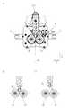
図1〜2に示すように、可搬型溶着装置2は、筐体10と、筐体10に内蔵された電源ユニット(図示省略)へ電力を供給する電源ケーブル20と、筐体10に設けられた加熱ヘッド30と、加熱ヘッド30へ電力を供給する電力供給部材40と、筐体10に設けられたローラ機構50と、加熱ヘッド30の姿勢を切り替えるヘッド切替機構60と、筐体10に設けられた把手機構70と、筐体10に設けられた操作機構80と、筐体10に設けられた表示機構90と、を備える。 As shown in FIGS. 1 and 2, the
筐体10は、直方体状に形成され、それぞれの辺は、X軸方向、Y軸方向、及びZ軸方向に延びる。また、電源ケーブル20は、導電性を有する線材と、線材を被覆するシース材等を備える。ここで、シース材の最外周部には、編み組構造を有するシース材が用いられることが好ましい。これにより、電源ケーブル20を引っ張った場合のテンションが、編み組構造によって吸収されるため、線材に伝わらずに済む。結果、線材の寿命が延びる。 The
ローラ機構50は、筐体10の正面10Fに設けられるものであり、円柱状の第1駆動ローラ51と、第1駆動ローラ51に対して平行に伸びる円柱状の第2駆動ローラ52と、を有する。第1駆動ローラ51の回転軸と第2駆動ローラ52の回転軸とは、いずれもX軸方向に平行となっていることが好ましい。第1駆動ローラ51と第2駆動ローラ52とは、内蔵モータに接続される。内蔵モータによって、第1駆動ローラ51と第2駆動ローラ52とは、それぞれ、等しい速度で逆方向に回転する(図3)。これにより、第1駆動ローラ51と第2駆動ローラ52との間に挿入されたシートSは、加圧されながら案内方向DGへ案内される。なお、本実施形態の案内方向DGは、Z軸方向に平行である。 The
なお、第1駆動ローラ51は、自身の回転軸に対して偏心していることが好ましい。これにより、第1駆動ローラ51が回転すると、第1駆動ローラ51の姿勢は、第2駆動ローラ52に対してシートSを強く押し当てる状態と、第2駆動ローラ52に対してシートSを弱く押し当てる状態と、を交互に切り替えることができる。シートSを弱く押し当てる状態では、第1駆動ローラ51と第2駆動ローラ52との隙間に対するシートSの挿抜が可能となる。シートSを弱く押し当てる状態とを切り替えが可能になる。また、第1駆動ローラ51のローラ軸を偏心させない場合には、第1駆動ローラ51が、第2駆動ローラ52から遠ざかる離隔位置と、離隔位置に比べ第2駆動ローラ52から近い接近位置との間で切替自在となっていてもよい。離隔位置にすることにより、第1駆動ローラ51と第2駆動ローラ52との隙間に対するシートSの挿抜が可能となる。 The
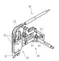
図3〜4に示すように、加熱ヘッド30は、シートSを加熱するものであり、ヘッド切替機構60を介して筐体10に設けられる。加熱ヘッド30は、電力供給部材40に接続するヒータ31と、ヒータ31によって加熱されるコテ32と、コテ32の温度を検知可能な温度センサ35とを、を備える。 As shown in FIGS. 3 to 4, the
コテ32は、ローラ機構50よりも案内方向DGの上流側に配されるものであり、案内方向DGの上流側から下流側に向かって先細となるような楔形に形成される。コテ32は、ヒータ31によって、シートSの温度がシートSの融点以上となるまで加熱される。 The
コテ32の材料の母材としては、銅鉄合金に無電解Ni-W-Bニッケルメッキが施されていることが好ましい。これにより、高い熱伝導率及び高い耐摺動性を実現するだけでなく、シートの溶着時に生成する炭素化合物の貼り付きの張り付きの抑制を実現することができる。なお、コテ32の材料の母材としては、銅鉄合金の他に、ステンレスや銅でもよい。また、メッキ処理としては、無電解Ni-W-Bニッケルメッキ以外のものでもよい。 As a base material of the material of the
シートSの材料としては、合成樹脂であることが好ましく、例えば、EVA樹脂(エチレン酢酸ビニル共重合樹脂)、PVC樹脂(ポリ塩化ビニル)、ポリエチレン(HDPE(高密度ポリエチレン)やLLDPE(リニアポリエチレン))、EVA(オレフィン系エラストマー)等がある。 The material of the sheet S is preferably a synthetic resin, for example, EVA resin (ethylene vinyl acetate copolymer resin), PVC resin (polyvinyl chloride), polyethylene (HDPE (high density polyethylene) or LLDPE (linear polyethylene)). ) And EVA (olefin elastomer).
ヘッド切替機構60は、シートSの加熱が可能な加熱可能位置(図3(B))と、加熱可能位置から退避した退避位置(図3(C))との間で、加熱ヘッド30を切替自在にするリンク構造61と、リンク構造61に連結する操作レバー62と、筐体10にリンク構造61を取り付ける取付構造63とを有する。操作レバー62の操作により、加熱ヘッド30は、加熱可能位置と退避位置との間で切替自在となる。加熱可能位置と、退避位置との切り替えにおいて、リンク構造61は、加熱ヘッド30をyz面内にて移動可能にする。 The
電力供給部材40は、ヒータ31に電力を供給する電力配線である。電力供給部材40は、筐体10の天面10Pを貫通するように配され、一端側は筐体10の内部に設けられた電源ユニットに接続され、他端側は、筐体10の天面10Pから外部へ露出して、ヒータ31へ接続している。なお、電力供給部材40の先端側は、基端側に比べ曲がりやすい軟性部となっていることが好ましい。これにより、加熱ヘッド30は、加熱可能位置と退避位置との間で切替操作が容易になる。 The
操作機構80は、各種操作をするものであり、筐体10の背面10Bには、電源スイッチ81や各種設定を行う操作つまみ82や操作スイッチ83が配される。電源スイッチ81は、内蔵電源へ給電がなされているON状態と給電がなされていないOFF状態を切り替えるものである。操作つまみ82や操作スイッチ83は、ヒータ31の加熱温度や、第1駆動ローラ51や第2駆動ローラ52の回転速度の調節を行うものである。 The operation mechanism 80 performs various operations, and a
表示機構90は、ON状態とOFF状態とのいずれであるか、モータの出力値や、センサが検知した値などを表示するものであり、具体的には、ランプや液晶ディスプレイなどが用いられる。このような表示機構は、筐体10の背面10Bに配される。センサとしては、ヒータ31の温度を検知する温度センサや、ヒータ31のダウンを検出する近接センサ等がある。 The
図1に示すように、把手機構70は、筐体10の天面10Pに設けられた天面把手71と、筐体10の側面10Sに設けられた側面把手72と、筐体10の背面10Bに設けられた背面把手73と、を有する。 As shown in FIG. 1, the handle mechanism 70 includes a
図6(A)に示すように、天面把手71は、電力供給部材40の配線ルートを囲むように配された配線ガード71Gと、天面10Pから起立するように設けられ配線ガード71Gを支持する配線ガードブラケット71Bと、を備える。 As shown in FIG. 6A, the
配線ガード71Gは、X方向に延びるものであり、Y方向においては第1駆動ローラ51及び第2駆動ローラ52の間に位置し、Z方向においては天面10Pから所定距離だけ離れている。そして、配線ガードブラケット71Bは、配線ガード71GのX方向両端を支持する。こうして、配線ガード71Gと天面10Pとの間に形成された隙間は、指や手が入る程度の大きさとなるため、配線ガード71Gが把手として機能する。 The
握りやすさの点から、yz平面における配線ガード71Gの断面形状は、図6(B)に示すように、曲線部を有することが好ましい。曲線部は、断面形状のうち、天面10Pに近い部分71GAと、天面10Pから遠い部分71GBに設けられることが好ましい。断面形状のうち、天面10Pに近い部分71GAと天面10Pから遠い部分71GBとの間(図中の71GC)は、曲線でも直線でもよい。 From the viewpoint of ease of gripping, the cross-sectional shape of the
天面把手71の材料は、金属やプラスチック等を用いることができるが、耐久性の点から、金属を用いることが好ましい。また、電力供給部材40の視認性を確保といったメンテナンス性や、軽量化のために、天面把手71は、パンチングなどにより、適宜孔が形成されていることが好ましい。 As the material of the
なお、配線ガード71Gは、正面側に位置する正面側ガード片71GYと、背面側に位置し背面側ガード片71GYに対して着脱自在な背面側ガード片71GXとを備えることが好ましい。これにより、電力供給部材40、加熱ヘッド30やヘッド切替機構60のメンテナンス時には、正面側ガード片71GYのみの着脱で済むため、作業性が向上する。なお、コテ32すなわち正面側ガード片71GYから、背面側ガード片71GXへの伝熱を防ぐために、正面側ガード片71GY及び背面側ガード片71GXの間に、シート状の断熱部材71GXを配することが好ましい。 The
側面把手72は、筐体10の両方の側面10Sに設けられる。側面把手72は、側面把手本体72Aと、側面把手ブラケット72Bと、を備える。側面把手本体72Aは、X方向に延びるものであり、Z方向においてはコテ32の先端と同程度の高さに位置し、Y方向においてはそれぞれの側面10Sから所定距離だけ離れている。そして、側面把手ブラケット72Bは、側面把手本体72AのX方向両端を支持する。なお、側面把手72は、筐体10の片方の側面10Sのみ設けられていてもよいが、可搬型溶着装置2による溶着の操作性を考慮すると、両方の側面10Sに設けられることが好ましい。 The side handle 72 is provided on both side surfaces 10 </ b> S of the
図1〜2に示すように、背面把手73は、筐体10の背面10Bに設けられる。背面把手73は、背面把手本体73Aと、背面把手ブラケット73Bと、を備える。背面把手本体73Aは、Y方向に延びるものであり、X方向においては背面10Bから所定距離だけ離れている。また、背面把手73は、Z方向においては、下端に位置してもよいし、コテ32の先端と同程度の高さに位置してもよい。なお、背面把手73の先端部は、筐体10が背面10B側から落下した際、背面10Bよりも先に、背面把手本体73Aが地面等にぶつかる程度となっていればよい。また、背面把手ブラケット73Bは、背面把手本体73AのY方向片端を支持する。なお、背面把手ブラケット73Bは、背面把手本体73AのY方向両端を支持していてもよいし、背面把手本体73AのY方向片端を支持していてもよい。 As illustrated in FIGS. 1 and 2, the
筐体10の底面10Bは、平置きを行いやすくするために、平らに形成されることが好ましい。また、可搬型であるため、キャスター等は、取り付けられて居ないことが好ましい。なお、キャスター等を底面10Bに取り付ける場合には、着脱自在となっていることが好ましい。 The
次に、可搬型溶着装置2の使用方法について説明する。 Next, the usage method of the
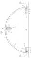
図8(A)に示すように、横坑SXの内周において、奥行き方向DDへ防水用のシートSが敷設される。そして、奥行き方向DDにおいて隣り合うシートSの端部同士は、横坑SXの面に対して起立するようにして重なっている(図8(B))。このシートSの端部同士が、シートSの重ね合わせ部分OLであり、溶着部分となる。図8(A)に示すように、重ね合わせ部分OLは、横坑SXの内周に沿った逆U字状となっている。ここで、重ね合わせ部分OLをなすシートSの間にコテ32が位置するように、可搬型溶着装置2をセットする。その後、電源スイッチ81(図5)をOFFからONにすると、第1駆動ローラ51及び第2駆動ローラ52の回転と、ヒータ31の加熱とが開始する。これにより、コテ32の近傍にある2枚のシートSは、コテ32によって加熱されながら、第1駆動ローラ51及び第2駆動ローラ52へ案内される(図3)。そして、第1駆動ローラ51及び第2駆動ローラ52によって、2枚のシートSは加圧され、溶着される。このように、案内方向DGにおいて、加熱ヘッド30は、ローラ機構50に対して近接しているため、シートSは、加熱ヘッド30及びローラ機構50によって溶着される。 As shown in FIG. 8A, a waterproof sheet S is laid in the depth direction DD on the inner periphery of the horizontal shaft SX. And the edge part of the sheet | seat S which adjoins in the depth direction DD has overlapped so that it might stand with respect to the surface of the horizontal shaft SX (FIG. 8 (B)). The ends of the sheet S are overlapped portions OL of the sheets S, which are welded portions. As shown in FIG. 8A, the overlapping portion OL has an inverted U shape along the inner periphery of the horizontal shaft SX. Here, the
ところで、重ね合わせ部分OLが逆U字状となっている場合(図9)には、重ね合わせ部分OLの向きに応じて、可搬型溶着装置2の姿勢を調節する必要がある。結果、可搬型溶着装置2による溶着軌跡YLは、重ね合わせ部分OLに沿う逆U字状となる。このように、逆U字状の重ね合わせ部分OLの溶着工程は、序盤で行われ横坑SXの壁部SXaを溶着する第1縦向き溶着ステップと、中盤で行われ横坑SXの天井部SXbを溶着する横向き溶着ステップと、終盤で行われ横坑SXの反対側の壁部SXcを溶着する第2縦向き溶着ステップと、を有する。 By the way, when the overlapping portion OL has an inverted U shape (FIG. 9), it is necessary to adjust the posture of the
ここで、横向き溶着ステップの横向きとは、案内方向DGが水平方向の場合に限られず、案内方向DGが水平方向から所定の角度(例えば、±45°)だけ傾いた方向の場合も含む。同様に、縦向き溶着ステップの縦向きとは、案内方向DGが垂直方向の場合に限られず、案内方向DGが垂直方向から所定の角度(例えば、±45°)だけ傾いた方向の場合も含む。 Here, the horizontal direction of the horizontal welding step is not limited to the case where the guide direction DG is the horizontal direction, but also includes the case where the guide direction DG is inclined by a predetermined angle (for example, ± 45 °) from the horizontal direction. Similarly, the vertical direction of the vertical welding step is not limited to the case where the guide direction DG is a vertical direction, but includes the case where the guide direction DG is inclined by a predetermined angle (for example, ± 45 °) from the vertical direction. .
第1縦向き溶着ステップでは、重ね合わせ部分OLが上方向に延びるため、筐体10の天面10Pを上向きにする必要がある。したがって、重力方向の支持は天面把手71を用い、加熱ヘッド30の進行方向における向き調整は、側面把手72を用いて、重ね合わせ部分OLの溶着を行う。 In the first vertical welding step, the overlapping portion OL extends upward, so that the
横向き溶着ステップでは、重ね合わせ部分OLが横方向に延びるため、筐体10の天面10Pが横向きにする必要がある。したがって、重力方向の支持は背面把手73を用い、加熱ヘッド30の進行方向における向き調整は、側面把手72を用いて、重ね合わせ部分OLの溶着を行う。 In the horizontal welding step, since the overlapping portion OL extends in the horizontal direction, the
なお、第1縦向き溶着ステップでは、筐体10の天面10Pを下向きにして溶着を行ってもよい。係る場合には、第2縦向き溶着ステップでは、筐体10の天面10Pを上向きにして溶着を行ってもよい。 In the first vertical welding step, welding may be performed with the
第2縦向き溶着ステップでは、重ね合わせ部分OLが縦方向に延びるため、筐体10の天面10Pが下向きにする必要がある。したがって、第2縦向き溶着ステップでは、天面把手71を用いて重力方向の支持を行うとともに、側面把手72を用いて加熱ヘッド30の進行方向における向き調整を行う。 In the second vertical welding step, since the overlapping portion OL extends in the vertical direction, the
このように、可搬型溶着装置2は、側面把手72のみならず、天面把手71を備えるため、縦向き溶着ステップにおける重力方向の支持が可能となる。このため、縦向き溶着ステップにおける重力方向の支持が容易となるため、作業者の負担が軽くなり、ひいては、作業効率が向上する。結果、シート溶着装置の落下や、これに伴う作業者の怪我やシート溶着装置の破損や故障を防止することができる。なお、天面把手71に替えて、底面10Bに設けられた底面把手を設けてもよいし、底面把手と天面把手71とを併用してもよい。 Thus, since the
同様に、可搬型溶着装置2は、背面把手73を備えるため、横向き溶着ステップにおける重力方向の支持が可能となる。このため、横向き溶着ステップにおける重力方向の支持が容易となる。 Similarly, since the
また、天面把手71は、電力供給部材40の配線ルートを囲むように配された配線ガード71Gを有するため、溶着操作時(特に、第1〜2縦向き溶着ステップ)において、作業者が電力供給部材40を直接つかむことが無い。このため、電力供給部材40の劣化や断線を未然に防ぐことができる。なお、配線ガード71Gは、電力供給部材40から加熱ヘッド30までを覆うことが好ましい。これにより、作業者のやけどや火災等、加熱ヘッド30との接触による事故を未然に防ぐことができる。 Further, since the
天面把手71が、電力供給部材40の配線ルートを囲むため、天面把手71を握る手により、電力供給部材40の異常発熱を検出することができる。 Since the top surface handle 71 surrounds the wiring route of the
なお、第1駆動ローラ51と第2駆動ローラ52とには、周溝が形成されることが好ましい。これにより、所定の間隔だけ離れた2本の溶着ラインが形成される。溶着ラインの間の被溶着ラインに空気を送り込み、空気の漏れの有無を調べることにより、溶着不良の有無を検知することができる。 The
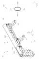
図10〜11に示すように、筐体10は、筒状体110と、筒状体110の両側に形成された開口110Xを塞ぐ蓋部材120と、筒状体110及び蓋部材120を連結する連結機構130と、を備えることが好ましい。筒状体110の外側面には、X方向に延びる蟻溝110Mが形成される。 As shown in FIGS. 10 to 11, the
さらに、連結機構130は、筒状体110の外側の面から窪む窪み部131と、窪み部131に載置された載置部材132と、ボルト133とを備える。窪み部131は、円形状に形成されるものであり、蟻溝110Mの中途部に位置することが好ましい。載置部材132は、円板状に形成されるものであり、ボルト133と螺合するボルト孔132Xを周面に有する。蓋部材120は、ボルト133が貫通する貫通孔120Xを有する。また、筒状体110及び蓋部材120の間には、パッキン140が挟まれることが好ましい。 Further, the coupling mechanism 130 includes a
筐体10の組立方法を説明する。 A method for assembling the
まず、筒状体110の内部に、電源ユニットや基板などが収容される。次に、窪み部131に載置部材132を載置する。載置部材132が窪み部131に載置された際、ボルト孔132XがX方向を向く(図11(B))。その後、筒状体110の開口110Xに対し、蓋部材120を用いて塞ぐ。このとき、筒状体110及び蓋部材120の間には、パッキン140が挟まれることが好ましい。このとき、貫通孔120Xとボルト孔132Xとが一直線上となるため、貫通孔120Xを介してボルト133をボルト孔132Xに螺合することができる(図11(A))。これにより、筒状体110及び蓋部材120の隙間におけるシール性が向上する。このため、高い防水機能を発揮することができる。 First, a power supply unit, a substrate, and the like are accommodated in the
なお、窪み部は、蓋部材120の外側の面に形成されていてもよい。係る場合には、筒状体110の外側の面にボルト孔に形成されていればよい。 The recess may be formed on the outer surface of the
なお、ボルト孔132Xの向きを決める向き決め機構を備えていてもよい。向き決め機構としては、キー及びキー溝や、ツマミなどがある。キー及びキー溝を設ける場合、片方を窪み部131にもう片方を載置部材132に形成することが好ましい。窪み部131に載置部材132を載置することにより、キー及びキー溝が係合し、ボルト孔132XがX方向を向く。また、ツマミを採用する場合は、ツマミを載置部材132の天面から突設させる。これにより、窪み部131に載置部材132を載置した際、ツマミは、筒状体10の面から突出する。したがって、窪み部131に載置部材132を載置した際、ツマミの操作により、ボルト孔132Xの向きを調節することができる。 An orientation determining mechanism that determines the orientation of the
尚、本発明は、上記した実施の形態に限定されるものではなく、本発明の要旨を逸脱しない範囲内において種々変更を加え得ることは勿論である。 It should be noted that the present invention is not limited to the above-described embodiment, and it is needless to say that various modifications can be made without departing from the gist of the present invention.
2 可搬型溶着装置
10 筐体
20 電源ケーブル
30 加熱ヘッド
40 電力供給部材
50 ローラ機構
60 ヘッド切替機構
70 把手機構
80 操作機構
90 表示機構
2
Claims (8)
Translated fromJapanese前記筐体の外部に設けられた把手機構と、
前記筐体の外部に設けられ、被溶着体を所定方向へ案内しながら、前記被溶着体の加圧を行う加圧部材と、
前記加圧部材よりも案内方向の上流側の前記筐体の外部に設けられ、前記被溶着体を加熱する加熱ヘッドと、を備え、
前記加圧部材や前記加熱ヘッドの操作を行う操作機構又は前記加圧部材や前記加熱ヘッドの出力条件を表示する表示機構が前記筐体に設けられたことを特徴とする可搬型の溶着装置。A housing,
A handle mechanism provided outside the housing;
A pressure member that is provided outside the housing and that pressurizes the welded body while guiding the welded body in a predetermined direction;
A heating head that is provided outside the casing on the upstream side in the guide direction with respect to the pressing member and heats the welded body,
A portable welding apparatus, wherein an operation mechanism for operating the pressure member and the heating head or a display mechanism for displaying output conditions of the pressure member and the heating head is provided in the casing.
筒状体と、
前記筒状体の開口を塞ぐ蓋部材と、
前記筒状体及び前記蓋部材を連結する連結機構と、を備え、
前記連結機構は、
前記筒状体または前記蓋部材のいずれか一方に設けられた窪み部と、
前記窪み部に載置される載置部材と、
ボルトと、を備え、
前記載置部材には前記ボルトと螺合するボルト孔が形成され、
前記筒状体または前記蓋部材の他方には前記ボルトが貫通する貫通孔が形成されることを特徴とする請求項1記載の可搬型の溶着装置。The housing is
A tubular body;
A lid member for closing the opening of the cylindrical body;
A coupling mechanism for coupling the tubular body and the lid member,
The coupling mechanism is
A recess provided in either the cylindrical body or the lid member;
A placement member placed in the recess,
A bolt, and
The mounting member is formed with a bolt hole screwed with the bolt,
The portable welding apparatus according to claim 1, wherein a through-hole through which the bolt passes is formed in the other of the cylindrical body or the lid member.
前記筐体において前記被溶着体の案内方向又はその反対方向へ突設された第1把手部材と、前記筐体に対して前記加熱ヘッド又は前記加圧部材の反対側に位置する第2把手部材と、のうち少なくとも一方を有することを特徴とする請求項1ないし3のうちいずれか1項記載の可搬型の溶着装置。The handle mechanism is
A first handle member protruding in the guide direction of the welded body in the casing or the opposite direction thereof, and a second handle member positioned on the opposite side of the heating head or the pressure member with respect to the casing. 4. The portable welding apparatus according to claim 1, wherein the portable welding apparatus includes at least one of the two.
前記抵抗体へ電力を供給する電力供給部材と、
前記電力供給部材を覆うカバー部材と、を備え、
前記カバー部材が前記把手機構を兼ねることを特徴とする請求項1ないし4のうちいずれか1項記載の可搬型の溶着装置。A resistor provided outside the housing;
A power supply member for supplying power to the resistor;
A cover member covering the power supply member,
The portable welding apparatus according to claim 1, wherein the cover member also serves as the handle mechanism.
前記保護部材が把手機構を兼ねることを特徴とする請求項1ないし6のうちいずれか1項記載の可搬型の溶着装置。A protective member for protecting the operation mechanism or the display mechanism;
The portable welding apparatus according to claim 1, wherein the protection member also serves as a handle mechanism.
前記案内方向が横方向となる姿勢の前記溶着装置を用いて、前記重ね合わせ部に溶着を行う横向き溶着ステップと、
前記案内方向が縦方向となる姿勢の前記溶着装置を用いて、前記重ね合わせ部に溶着を行う縦向き溶着ステップと、
を備えたことを特徴とする溶着方法。A welding method using the welding device according to any one of claims 1 to 7, wherein welding is performed on an overlapping portion of sheets,
Using the welding apparatus in a posture in which the guide direction is a lateral direction, a lateral welding step of performing welding on the overlapping portion;
Using the welding apparatus in a posture in which the guide direction is the vertical direction, a vertical welding step of performing welding on the overlapping portion;
A welding method characterized by comprising:
Priority Applications (1)
| Application Number | Priority Date | Filing Date | Title |
|---|---|---|---|
| JP2017009032AJP2018114739A (en) | 2017-01-21 | 2017-01-21 | Portable welding apparatus and welding method |
Applications Claiming Priority (1)
| Application Number | Priority Date | Filing Date | Title |
|---|---|---|---|
| JP2017009032AJP2018114739A (en) | 2017-01-21 | 2017-01-21 | Portable welding apparatus and welding method |
Publications (1)
| Publication Number | Publication Date |
|---|---|
| JP2018114739Atrue JP2018114739A (en) | 2018-07-26 |
Family
ID=62983734
Family Applications (1)
| Application Number | Title | Priority Date | Filing Date |
|---|---|---|---|
| JP2017009032APendingJP2018114739A (en) | 2017-01-21 | 2017-01-21 | Portable welding apparatus and welding method |
Country Status (1)
| Country | Link |
|---|---|
| JP (1) | JP2018114739A (en) |
Cited By (1)
| Publication number | Priority date | Publication date | Assignee | Title |
|---|---|---|---|---|
| CN109747161A (en)* | 2019-01-23 | 2019-05-14 | 烟台金正环保科技有限公司 | A kind of ultrasonic welding machine |
Citations (5)
| Publication number | Priority date | Publication date | Assignee | Title |
|---|---|---|---|---|
| JPS63107541A (en)* | 1986-10-24 | 1988-05-12 | Keiichi Isotani | Handy type hot welder |
| JP2000272611A (en)* | 1999-03-23 | 2000-10-03 | Fuji Impulse Kk | Heat sealer |
| JP2008229763A (en)* | 2007-03-19 | 2008-10-02 | Hitachi Koki Co Ltd | Portable tools |
| JP2014087896A (en)* | 2012-10-31 | 2014-05-15 | Hitachi Koki Co Ltd | Portable tool |
| JP2015123645A (en)* | 2013-12-26 | 2015-07-06 | 藤森工業株式会社 | Sheet welding apparatus and welding pressure roller used therefor |
- 2017
- 2017-01-21JPJP2017009032Apatent/JP2018114739A/enactivePending
Patent Citations (5)
| Publication number | Priority date | Publication date | Assignee | Title |
|---|---|---|---|---|
| JPS63107541A (en)* | 1986-10-24 | 1988-05-12 | Keiichi Isotani | Handy type hot welder |
| JP2000272611A (en)* | 1999-03-23 | 2000-10-03 | Fuji Impulse Kk | Heat sealer |
| JP2008229763A (en)* | 2007-03-19 | 2008-10-02 | Hitachi Koki Co Ltd | Portable tools |
| JP2014087896A (en)* | 2012-10-31 | 2014-05-15 | Hitachi Koki Co Ltd | Portable tool |
| JP2015123645A (en)* | 2013-12-26 | 2015-07-06 | 藤森工業株式会社 | Sheet welding apparatus and welding pressure roller used therefor |
Cited By (1)
| Publication number | Priority date | Publication date | Assignee | Title |
|---|---|---|---|---|
| CN109747161A (en)* | 2019-01-23 | 2019-05-14 | 烟台金正环保科技有限公司 | A kind of ultrasonic welding machine |
Similar Documents
| Publication | Publication Date | Title |
|---|---|---|
| CN105358433B (en) | Knot installation with display and operation device | |
| AU2009222569B2 (en) | Welder with integrated regulator | |
| CN109974871A (en) | Temperature sensor band | |
| CN100591513C (en) | a welding device | |
| US20130134134A1 (en) | Burner body comprising a securing system; tig welding torch comprising such a burner body | |
| JP2017170526A (en) | System and method for remote-controlled engine drive welding power supply | |
| KR101995167B1 (en) | A portable dust collector improved workability | |
| JP2018114739A (en) | Portable welding apparatus and welding method | |
| EP2745653A1 (en) | Plasma torch and torch handle having ergonomic features | |
| US9180587B2 (en) | Non-welding device powered by a welding power supply | |
| US6172334B1 (en) | Tool kit for shielded metal-arc welding | |
| JP2022506388A (en) | Wire feeder | |
| CN107234373B (en) | Plate body welder | |
| CN104227205A (en) | Robot welding system with continuous stations | |
| JP7012206B2 (en) | Welder remote controller and welding torch | |
| KR20100002058U (en) | Torch for Tig Welder | |
| JP6821902B2 (en) | Thermal processing torch, power supply, wire feeder, and thermal processing system | |
| KR100985699B1 (en) | Cordless Iron | |
| JP2011183421A (en) | Spot welding machine | |
| JP5516966B2 (en) | Spot welder | |
| CN213592028U (en) | Electric welding machine clamping type welding gun handle | |
| CN104758001A (en) | Omnibearing ultrasonic diagnosis device | |
| CN222238580U (en) | Portable multifunctional air-breathing movable cutting machine | |
| KR102585774B1 (en) | carbon dioxide gas welding torch | |
| US20090078688A1 (en) | System and method of operating a welding gun |
Legal Events
| Date | Code | Title | Description |
|---|---|---|---|
| A80 | Written request to apply exceptions to lack of novelty of invention | Free format text:JAPANESE INTERMEDIATE CODE: A80 Effective date:20170215 | |
| A621 | Written request for application examination | Free format text:JAPANESE INTERMEDIATE CODE: A621 Effective date:20191225 | |
| A977 | Report on retrieval | Free format text:JAPANESE INTERMEDIATE CODE: A971007 Effective date:20201026 | |
| A131 | Notification of reasons for refusal | Free format text:JAPANESE INTERMEDIATE CODE: A131 Effective date:20201028 | |
| A02 | Decision of refusal | Free format text:JAPANESE INTERMEDIATE CODE: A02 Effective date:20210416 |