JP2018103130A - Raw water supplying device and method - Google Patents
Raw water supplying device and methodDownload PDFInfo
- Publication number
- JP2018103130A JP2018103130AJP2016254064AJP2016254064AJP2018103130AJP 2018103130 AJP2018103130 AJP 2018103130AJP 2016254064 AJP2016254064 AJP 2016254064AJP 2016254064 AJP2016254064 AJP 2016254064AJP 2018103130 AJP2018103130 AJP 2018103130A
- Authority
- JP
- Japan
- Prior art keywords
- raw water
- tank
- reaction tank
- water
- water supply
- Prior art date
- Legal status (The legal status is an assumption and is not a legal conclusion. Google has not performed a legal analysis and makes no representation as to the accuracy of the status listed.)
- Granted
Links
Images


Classifications
- Y—GENERAL TAGGING OF NEW TECHNOLOGICAL DEVELOPMENTS; GENERAL TAGGING OF CROSS-SECTIONAL TECHNOLOGIES SPANNING OVER SEVERAL SECTIONS OF THE IPC; TECHNICAL SUBJECTS COVERED BY FORMER USPC CROSS-REFERENCE ART COLLECTIONS [XRACs] AND DIGESTS
- Y02—TECHNOLOGIES OR APPLICATIONS FOR MITIGATION OR ADAPTATION AGAINST CLIMATE CHANGE
- Y02W—CLIMATE CHANGE MITIGATION TECHNOLOGIES RELATED TO WASTEWATER TREATMENT OR WASTE MANAGEMENT
- Y02W10/00—Technologies for wastewater treatment
- Y02W10/10—Biological treatment of water, waste water, or sewage
Landscapes
- Separation Using Semi-Permeable Membranes (AREA)
- Activated Sludge Processes (AREA)
- Purification Treatments By Anaerobic Or Anaerobic And Aerobic Bacteria Or Animals (AREA)
Abstract
Translated fromJapaneseDescription
Translated fromJapanese本発明は、活性汚泥処理等の生物処理を行う反応槽に原水を供給するための原水供給装置及び原水供給方法に関する。更に詳しくは、生物処理を行う反応槽に、貯水槽とサイホン管を用いて、原水を一定のサイクルで間欠的に供給する原水供給装置及び原水供給方法に関する。 The present invention relates to a raw water supply apparatus and a raw water supply method for supplying raw water to a reaction tank that performs biological treatment such as activated sludge treatment. More specifically, the present invention relates to a raw water supply apparatus and a raw water supply method for supplying raw water intermittently in a constant cycle using a water storage tank and a siphon tube to a reaction tank that performs biological treatment.
従来から、窒素やリンといった栄養塩を含む下廃水を処理するにあたっては、汚水を反応槽に導入し活性汚泥と共に曝気・攪拌して生物処理を行う活性汚泥法が用いられている。特に近年は、この活性汚泥法によって処理された処理水から固形物を含まない清澄な処理水を得るため、反応槽内に膜分離装置を浸漬させ、処理水を膜分離して排出する膜分離活性汚泥法(Membrane Bioreactor(MBR)法)が多用されている。 Conventionally, when treating sewage wastewater containing nutrient salts such as nitrogen and phosphorus, an activated sludge method is used in which sewage is introduced into a reaction tank and aerated and agitated together with activated sludge for biological treatment. Especially in recent years, in order to obtain clear treated water that does not contain solid matter from the treated water treated by this activated sludge method, membrane separation is performed by immersing the membrane separation device in the reaction tank and separating the treated water into a membrane. The activated sludge method (Membrane Bioreactor (MBR) method) is frequently used.
例えば、浸漬膜分離ユニットを配置した単一の反応槽内で、硝化のための好気性処理(曝気工程)と脱窒のための無酸素処理(嫌気工程)を行う膜分離活性汚泥処理装置が提案されている(特許文献1および特許文献2)。特許文献1の装置では、反応槽内で嫌気工程が開始されると共に汚水移送ポンプを作動させて反応槽に汚水(原水)を供給し、反応槽内の水位が最高水位に達した時点で汚水移送ポンプを停止させることにより、原水が反応槽に間欠的に供給されている。また、特許文献2の装置では、反応槽内が最高液位と最低液位になった時点をレベルセンサーにより検知し、この検知に基づいて原水ポンプをON−OFFすることにより、原水が反応槽に間欠的に供給されている。 For example, a membrane separation activated sludge treatment apparatus that performs an aerobic treatment (aeration process) for nitrification and an oxygen-free treatment (anaerobic process) for denitrification in a single reaction tank in which a submerged membrane separation unit is arranged. It has been proposed (
ところで、従来から活性汚水処理装置においては、反応槽に供給される原水中の有機物や繊維質により、反応槽に原水を供給する原水供給管や、ポンプおよびバルブ等の機器において詰まりが生じることが問題となっており、特に、ポンプやバルブ等を用いて原水の供給流量の制御を行う場合に、これらの機器において詰まりが生じることが問題となっていた。 By the way, in the conventional activated sewage treatment apparatus, clogging may occur in raw water supply pipes for supplying raw water to the reaction tank, equipment such as pumps and valves, etc., due to organic matter and fibers in the raw water supplied to the reaction tank. In particular, when the supply flow rate of raw water is controlled using a pump or a valve, clogging occurs in these devices.
このような問題を解決するために、原水供給管の一部を反応槽外に延設し、2種類のバルブを設けることにより、原水供給管に生じた詰まりを除去する原水供給装置が提案されている(特許文献3)。しかしながら、特許文献3の装置は、バルブの開閉により原水の流路を変更させながら、原水供給管の詰まりを除去する装置であり、ポンプやバルブ等の機器における詰まりの問題を解消するものではなかった。
また、従来は原水を間欠的に反応槽に供給するために、ポンプを一定のサイクルでON−OFFする必要があり、原水ポンプの運転負荷が大きく、ポンプの寿命が短いという問題があった。さらに、ポンプの稼働率を大きく変動させる必要があったため、ポンプを過剰設計する必要があった。In order to solve such a problem, a raw water supply device has been proposed in which a part of the raw water supply pipe is extended outside the reaction tank and two kinds of valves are provided to remove clogging generated in the raw water supply pipe. (Patent Document 3). However, the device of
Further, conventionally, in order to supply raw water intermittently to the reaction tank, it is necessary to turn the pump on and off at a constant cycle, and there is a problem that the operation load of the raw water pump is large and the life of the pump is short. Furthermore, since it was necessary to greatly change the operation rate of the pump, it was necessary to overdesign the pump.
本発明は、上記従来の課題に鑑み、活性汚泥処理等の生物処理を行う反応槽に原水を間欠的に供給する際に、ポンプやバルブ等の機器の詰まりの問題を解消でき、また、原水ポンプの運転負荷を低減し、ポンプの過剰設計が不要となる原水供給装置および原水供給方法を提供することを目的とする。 In view of the above-described conventional problems, the present invention can solve the problem of clogging of equipment such as pumps and valves when supplying raw water intermittently to a reaction tank that performs biological treatment such as activated sludge treatment. An object of the present invention is to provide a raw water supply device and a raw water supply method that reduce the operation load of the pump and eliminate the need for excessive pump design.
本願発明者らは、上記課題について鋭意検討した結果、生物処理を行う反応槽に原水を間欠的に供給する際に、少なくとも、貯水槽と、貯水槽の内部から貯水槽槽壁の上部を経て貯水槽の外部に延在するよう設けられたサイホン管を用いることにより、上記問題を解決できることを見出し、本発明を完成した。 As a result of earnestly examining the above problems, the inventors of the present application have at least a water storage tank and an interior of the water storage tank through the upper part of the water storage tank wall when intermittently supplying raw water to a reaction tank that performs biological treatment. The present inventors have found that the above problem can be solved by using a siphon tube provided so as to extend to the outside of the water storage tank, and completed the present invention.
すなわち本発明は、以下の(1)〜(9)に関する。
(1)生物処理を行う反応槽に原水を供給するための原水供給装置であって、貯水槽と、貯水槽の内部から貯水槽槽壁の上部を経て貯水槽の外部に延在するよう設けられたサイホン管とを備える原水供給装置。
(2)前記反応槽が、好気性処理および無酸素処理を単一の反応槽内で行う反応槽である、(1)記載の原水供給装置。
(3)前記反応槽が、浸漬膜分離ユニットと曝気手段とを内部に配置する反応槽である、(1)または(2)記載の原水供給装置。
(4)前記原水供給装置が、貯水槽内の原水の一部を貯水槽槽壁の一部から抜き出し、貯水槽の外部であって貯水槽よりも低位にある前記サイホン管の側部に供給する補助配管を更に備える、(1)〜(3)のいずれかに記載の原水供給装置。That is, the present invention relates to the following (1) to (9).
(1) A raw water supply device for supplying raw water to a reaction tank that performs biological treatment, and is provided to extend from the inside of the water tank to the outside of the water tank through the upper part of the water tank wall A raw water supply device comprising a siphon tube.
(2) The raw water supply apparatus according to (1), wherein the reaction tank is a reaction tank that performs aerobic treatment and oxygen-free treatment in a single reaction tank.
(3) The raw water supply apparatus according to (1) or (2), wherein the reaction tank is a reaction tank in which the submerged membrane separation unit and the aeration means are disposed.
(4) The raw water supply device extracts a part of the raw water in the water tank from a part of the wall of the water tank and supplies it to the side of the siphon pipe outside the water tank and lower than the water tank. The raw water supply apparatus according to any one of (1) to (3), further including an auxiliary pipe.
(5)生物処理を行う反応槽に原水を供給する原水供給方法であって、貯水槽と、貯水槽の内部から貯水槽槽壁の上部を経て貯水槽の外部に延在するよう設けられたサイホン管を用いて、原水を一定のサイクルで間欠的に前記反応槽に供給する原水供給方法。
(6)前記反応槽が、好気性処理および無酸素処理を単一の反応槽内で行う反応槽である、(5)記載の原水供給方法。
(7)前記反応槽が、浸漬膜分離ユニットと曝気手段とを内部に配置する反応槽である、(5)または(6)記載の原水供給方法。
(8)前記反応槽への原水の供給が、貯水槽内の原水の一部を抜き出し、貯水槽の外部であって貯水槽よりも低位にあるサイホン管の側部に供給する補助配管を更に用いて行われる、(5)〜(7)のいずれかに記載の原水供給方法。
(9)前記反応槽内に原水を一定流量で供給する工程と、前記工程における原水の供給流量よりも多い流量の原水を反応槽内に供給する工程と、原水の供給を停止する工程とを、この順で繰り返し行う、(5)〜(8)のいずれかに記載の膜分離活性汚泥処理方法。(5) A raw water supply method for supplying raw water to a reaction tank that performs biological treatment, and is provided so as to extend from the inside of the water storage tank to the outside of the water storage tank through the upper part of the water storage tank wall. A raw water supply method in which raw water is intermittently supplied to the reaction tank at a constant cycle using a siphon tube.
(6) The raw water supply method according to (5), wherein the reaction tank is a reaction tank that performs aerobic treatment and oxygen-free treatment in a single reaction tank.
(7) The raw water supply method according to (5) or (6), wherein the reaction tank is a reaction tank in which the submerged membrane separation unit and the aeration means are disposed.
(8) Auxiliary piping for supplying raw water to the reaction tank further extracts a part of the raw water in the water tank and supplies it to the side portion of the siphon pipe outside the water tank and lower than the water tank. The raw water supply method according to any one of (5) to (7), wherein the method is used.
(9) A step of supplying raw water into the reaction tank at a constant flow rate, a step of supplying raw water at a flow rate larger than the supply flow rate of raw water in the step, and a step of stopping the supply of raw water The membrane separation activated sludge treatment method according to any one of (5) to (8), which is repeated in this order.
本発明によれば、貯水槽とサイホン管を用い、原水を貯水槽に常に一定流量で連続的に供給するという簡便な方法により、貯水槽から反応槽に原水を一定のサイクルで間欠的に供給することができるため、ポンプやバルブを用いて反応槽に供給する原水の流量を制御する必要がない。そのため、ポンプやバルブ等の機器に生じる詰まりの問題を低減でき、原水ポンプの運転負荷を平滑化でき、ポンプの寿命を延長できる。また、原水ポンプの稼働率を変動させる必要がないため、原料ポンプの過剰設計が不要となる。その結果、コスト削減が可能となり、装置全体のメンテナンス性が向上するという利点がある。 According to the present invention, using a water tank and a siphon tube, the raw water is intermittently supplied from the water tank to the reaction tank in a constant cycle by a simple method of continuously supplying the raw water to the water tank at a constant flow rate. Therefore, it is not necessary to control the flow rate of raw water supplied to the reaction tank using a pump or a valve. Therefore, the problem of clogging occurring in devices such as pumps and valves can be reduced, the operating load of the raw water pump can be smoothed, and the life of the pump can be extended. In addition, since it is not necessary to change the operating rate of the raw water pump, an excessive design of the raw material pump becomes unnecessary. As a result, the cost can be reduced, and there is an advantage that the maintainability of the entire apparatus is improved.
本発明の原水供給装置および原水供給方法は、活性汚泥処理等の生物処理を行う反応槽に原水を供給するための装置および方法である。以下、図面に基づいて、本発明に係る原水供給装置および原水供給方法の実施態様を説明する。 The raw water supply apparatus and raw water supply method of the present invention are an apparatus and method for supplying raw water to a reaction tank that performs biological treatment such as activated sludge treatment. Hereinafter, based on the drawings, embodiments of the raw water supply apparatus and the raw water supply method according to the present invention will be described.
本発明に係る原水供給装置の一実施態様を図1に示す。
原水供給装置10には、原水槽から一定の流量で供給された原水を貯える貯水槽12と、貯水槽12の内部から貯水槽槽壁の上部、好ましくは貯水槽槽壁の上端を介して貯水槽12の外部に延在するサイホン管13が設けられている。ここで、サイホン管とは、液体は液面の高い方から低い方に向かって流れ移るという液体の性質を利用して、液体を一度高所に上げて低所に移すために用いる曲管を意味する。One embodiment of the raw water supply apparatus according to the present invention is shown in FIG.
The raw
このような構成により、原水槽から貯水槽12に原水が一定流量で供給され、貯水槽12内の水位が一定水位に到達するまでは、サイホン管から反応槽に原水が供給されない工程(原水停止工程)と、貯水槽12内の水位が一定水位、即ち、サイホン管13が貯水槽12の槽壁の上端で曲折する部分に相当する水位に到達すると、貯水槽内のほぼ全ての原水がサイホン管13を通して反応槽に供給される工程(原水供給工程)を、一定のサイクルで繰り返し行うことが可能となる。本発明において「一定流量」とは、ある所定の時間において流量が一定であればよく、最適な流量とするために変更されることがあってもよい。 With such a configuration, the raw water is supplied from the raw water tank to the
貯水槽の満水時容量は、通常反応槽容量の0.5〜30%であり、好ましくは1〜10%である。サイホン管の内径は、詰まり防止の点から、通常50mm以上、好ましくは100mm以上、更に好ましくは200mm以上である。貯水槽内外に延在するサイホン管端部の位置は、貯水槽内部に存在するサイホン管の端部よりも、貯水槽外部に存在するサイホン管の端部が低位となるよう設置する必要がある。また、貯水槽内部に存在するサイホン管の端部は、必要な原水量を反応槽に供給できる深度に設置する。 The full capacity of the water storage tank is usually 0.5 to 30%, preferably 1 to 10% of the reaction tank capacity. The inner diameter of the siphon tube is usually 50 mm or more, preferably 100 mm or more, and more preferably 200 mm or more from the viewpoint of preventing clogging. The position of the end of the siphon pipe extending inside and outside the water storage tank needs to be installed so that the end of the siphon pipe existing outside the water storage tank is lower than the end of the siphon pipe existing inside the water storage tank. . Moreover, the end part of the siphon tube existing inside the water storage tank is installed at a depth at which a necessary amount of raw water can be supplied to the reaction tank.
サイホン管13は、貯水槽12の内部から貯水槽槽壁の上部を介して貯水槽12の外部に延在するものであれば、貯水槽12の槽壁と独立して設置されてもよいが、省スペース及びコスト削減の点から、貯水槽12の槽壁と一体となって構成されていてもよい。
原水供給装置10には、万一サイホン管が閉塞し原料が漏洩した場合に対処可能なように、貯水槽内の高水位を感知できる水位センサーを備えた緊急停止装置やバイパス配管を設置することができる。The
The raw
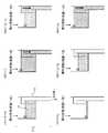
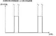
この原水供給装置10により原水が反応槽1に供給される態様を、図1の時系列(i)〜(vi)に沿って、図2(図1の原水供給装置から反応槽に供給される原水の流量変動)を参照しつつ説明する。 A mode in which raw water is supplied to the
図1(i)t=0〜t1(反応槽への原水の供給が停止)
原水槽から貯水槽12に原水が一定流量で供給されると、貯水槽12内に原水が貯留され水位が上昇していくが、水位が一定水位に到達するまでは、サイホン管から反応槽に原水が供給されることはない。したがって、この時間帯(t=0〜t1)において、サイホン管により反応槽に供給される原水の流量は0である(図2:t=0〜t1)。FIG. 1 (i) t = 0 to t1(supply of raw water to the reaction tank is stopped)
When raw water is supplied from the raw water tank to the
図1(ii)〜(iv)t=t1〜t2(サイホン管により原水が反応槽に供給)
次いで、貯水槽12内の水位が、一定水位、即ち、サイホン管13が貯水槽12の槽壁の上端で曲折する部分に相当する水位に到達すると、貯水槽内の原水がサイホン管13を通して反応槽に供給され始め(t=t1)、その後貯水槽12内のほぼ全ての原水が反応槽に供給され、貯水槽12およびサイホン管13の内部は、原水の存在しないほぼ空の状態となる(t=t2)。したがって、この時間帯(t=t1〜t2)においては、原水が一定流量でサイホン管を通して反応槽に供給される(図2:t=t1〜t2)。Figure 1 (ii) ~ (iv) t =
Next, when the water level in the
図1(v)t=t2〜t3(反応槽への原水の供給が停止)
その後も、原水は一定の流量で貯水槽12に供給され続けるため原水は貯水槽12内に貯留していくが、貯水槽12内の水位が前記一定水位に到達するまでは、原水がサイホン管13から反応槽に供給されることはない。したがって、この時間帯(t=t2〜t3)における反応槽への原水の供給流量は0となる(図2:t=t2〜t3)。Figure1 (v) t = t 2 ~t 3 (supply of raw water stop into the reaction vessel)
After that, since the raw water continues to be supplied to the
図1(vi)t=t3(サイホン管による原水の供給が再開)
貯水槽12内の水位が前記一定水位に到達すると、サイホン管による原水の反応槽への供給が再開される(図2:t=t3)。Fig. 1 (vi) t = t3(Raw water supply resumed through siphon tube)
When the water level in the
以上のような貯水槽とサイホン管を有する原水供給装置10を用いることにより、原水供給装置から反応槽に原水を供給する際にポンプやバルブ等の機器を用いて供給流量を制御しなくても、一定のサイクルで原水を間欠的に反応槽に供給することができる。 By using the raw
なお、原水供給装置10においても、原水槽から貯水槽に原水を供給する際に原水ポンプを使用するが、このポンプでは原水を常に一定流量で連続的に貯水槽に供給すればよいため、従来法のように原水ポンプやバルブをON−OFFさせて使用する場合に比べ、原水ポンプの運転負荷が小さく、原水ポンプの過剰設計が不要となる。 In the raw
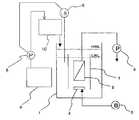
本発明の原水供給装置の別の実施態様を図3に示す。図3の原水供給装置10’には、原水槽から供給された原水を貯える貯水槽12と、貯水槽12の内部から貯水槽槽壁の上部を介して貯水槽12の外部に延在するサイホン管13に加え、貯水槽12内の原水の一部を貯水槽12の槽壁の一部から抜き出し、貯水槽12の外部であって貯水槽よりも低位にあるサイホン管13の側部に供給する補助配管14が設けられている。 Another embodiment of the raw water supply apparatus of the present invention is shown in FIG. 3 includes a
図3のような装置構成により、サイホン管を通して原水を間欠的に反応槽に供給すると共に、全ての原水がサイホン管により反応槽に供給される前には、補助配管14により一定流量の原水を反応槽に供給することができる。また、図3のような装置構成により、補助配管14を通して少量の原水を一定流量で反応槽に供給する工程と、前記工程における原水供給流量よりも多い流量の原水を一定流量で反応槽に供給する工程と、原水の供給を停止する工程とを、この順で一定のサイクルで繰り返し行うことができる。 3, the raw water is intermittently supplied to the reaction tank through the siphon tube, and before all the raw water is supplied to the reaction tank through the siphon tube, the
サイホン管および補助配管のそれぞれの寸法や配置位置は、反応槽に供給する原水の量や流量変動により変わり得るが、補助配管とサイホン管の内径比率は、通常1:2〜10であり、好ましくは1:2〜5である。また、補助配管を結合させる貯水槽の底面からの位置は、通常、貯水槽底部からサイホン管上端までの高さの20〜90%の範囲でありであり、好ましくは40〜60%となるよう設定する。補助配管14は、サイホン管が設置された貯水槽の槽壁に対向する槽壁に結合していることが好ましい。 The dimensions and arrangement positions of the siphon pipe and the auxiliary pipe may vary depending on the amount of raw water supplied to the reaction tank and the flow rate fluctuation, but the inner diameter ratio of the auxiliary pipe and the siphon pipe is usually 1: 2 to 10, preferably Is 1: 2-5. Moreover, the position from the bottom surface of the water storage tank to which the auxiliary pipe is coupled is usually in the range of 20 to 90% of the height from the bottom of the water storage tank to the upper end of the siphon tube, and preferably 40 to 60%. Set. The
本発明の原水供給装置が原水を供給する反応槽は、活性汚泥法や生物膜法等の生物処理を行う反応槽であって、原水が間欠的に供給される反応槽であれば特に限定されない。このような反応槽を有する活性汚泥処理装置としては、例えば、単一の反応槽内で、硝化のための好気性処理(曝気工程)と脱窒のための無酸素処理(嫌気工程)を行う装置や、複数の反応槽を用い、好気性処理(曝気工程)と無酸素処理(嫌気工程)を別々の反応槽内で行う装置が挙げられる。また、無酸素処理工程(嫌気工程)においては、脱窒を行うために有機物をはじめとする電子供与体が必要になるため、原水供給装置から供給される原水は、脱窒を行う無酸素処理が行われる領域に供給するのが好ましい。 The reaction tank to which the raw water supply apparatus of the present invention supplies raw water is a reaction tank that performs biological treatment such as an activated sludge method or a biofilm method, and is not particularly limited as long as the raw water is intermittently supplied. . As an activated sludge treatment apparatus having such a reaction tank, for example, an aerobic process (aeration process) for nitrification and an anaerobic process (anaerobic process) for denitrification are performed in a single reaction tank. An apparatus or an apparatus that uses a plurality of reaction tanks and performs aerobic treatment (aeration process) and anaerobic treatment (anaerobic process) in separate reaction tanks. In addition, in the anaerobic treatment process (anaerobic process), an electron donor such as an organic substance is required to perform denitrification. Therefore, the raw water supplied from the raw water supply apparatus is subjected to deoxygenation. It is preferable to supply to the area where the
貯水槽とサイホン管と補助配管を有する原水供給装置10’(図3)は、前述のように3つの工程を特定の順序で、かつ、一定のサイクルで繰り返し行うことができるという点で、仕切板挿入型の膜分離活性汚泥処理装置(Baffled Membrane Bioreactor(B−MBR法))と組み合わせて用いることが好ましい。 The raw
ここで仕切板挿入型の膜分離活性汚泥処理装置とは、図5に示すように、好気性処理および無酸素処理を行う単一の反応槽と、その反応槽の内部に配置された浸漬膜分離ユニットと、曝気手段とを有する装置であって、反応槽が、底部が反応槽の底面から離間して設けられた仕切板によって複数個の区画に分割され、その複数個の区画のうちの少なくとも一つの区画を、浸漬膜分離ユニットおよび曝気手段が配置された好気区画とし、その他の区画内を、好気状態から無酸素状態に、また、無酸素状態から好気状態に切り換えるための区画とする装置である。なお、ここで「無酸素状態」とは、完全な無酸素状態のみを意味するものではなく、脱窒菌の作用により硝酸態窒素を窒素分子に還元できる程度に酸素濃度が低い状態をも包含する意味で用いる。 Here, as shown in FIG. 5, a partition plate insertion type membrane separation activated sludge treatment apparatus includes a single reaction tank for performing an aerobic treatment and an oxygen-free treatment, and a submerged membrane disposed in the reaction tank. An apparatus having a separation unit and an aeration means, wherein the reaction tank is divided into a plurality of compartments by a partition plate having a bottom portion spaced apart from the bottom surface of the reaction tank, of the plurality of compartments. At least one of the compartments is an aerobic compartment in which the submerged membrane separation unit and the aeration means are arranged, and the other compartments are switched from an aerobic state to an anaerobic state and from an anaerobic state to an aerobic state. It is a device used as a partition. Here, the “anoxic state” does not mean only a complete anoxic state but also includes a state where the oxygen concentration is low enough to reduce nitrate nitrogen to nitrogen molecules by the action of denitrifying bacteria. Used in meaning.
以下に、本発明の原水供給装置を組み合わせた仕切板挿入型膜分離活性汚泥装置の概要について、図5に基づき説明する。膜分離活性汚泥装置には、単槽式の反応槽1が設けられ、この反応槽1には浸漬型の膜分離ユニット2が設けられている。この膜分離ユニット2には反応槽1の外で吸引ポンプ3が接続されるとともに、膜分離ユニット2の下方に、膜洗浄および好気生物処理用の散気管4が設けられている。散気管4は、ブロワ5に接続され、ブロワ5からエア(空気)が供給される。反応槽1には、微生物を含有する汚泥が収容されており、この微生物が、有機物の分解菌、さらにはそれら微生物の分解菌として作用し、生物処理を行う。なお、これらの微生物を含有する汚泥自体はこの分野において周知である。 Below, the outline | summary of the partition plate insertion type | mold membrane separation activated sludge apparatus which combined the raw | natural water supply apparatus of this invention is demonstrated based on FIG. The membrane separation activated sludge apparatus is provided with a single tank
さらに、この反応槽1に浸漬させる膜分離ユニット2には、精密ろ過膜、限外ろ過膜、ナノろ過膜、逆浸透膜などを用いて形成されたモジュールを用いることができる。経済性の観点からは、ろ過速度が高くコンパクト化が可能で、メンテナンスが容易である精密ろ過膜、限外ろ過膜を用いたモジュールが好ましい。膜の形状は平膜、中空糸膜等のものが用いられる。ここで用いられる浸漬型膜分離ユニット自体はこの分野において広く用いられており、市販もされている。 Furthermore, a module formed using a microfiltration membrane, an ultrafiltration membrane, a nanofiltration membrane, a reverse osmosis membrane, or the like can be used for the
このような図5に示す装置構成により、反応槽1内で汚水が生物学的に処理され、散気管4からのエアによって、膜分離ユニット2の膜面に汚泥物質等が付着するのを防止しながら、膜分離ユニット2によって反応槽1内の処理液をろ過し、そのろ過水を吸引ポンプ3により吸引して槽外に取り出すことができる。 With such an apparatus configuration shown in FIG. 5, sewage is biologically treated in the
図5の反応槽1には、原水供給装置10’が接続されるとともに、レベルセンサー6および仕切板7が設けられている。レベルセンサー6は、液位、すなわち、液表面の位置を調べるセンサーであり、それ自体は周知である。また、仕切板7は、図5に示すように底部が反応槽の底面から離間して設けられている。仕切板7は、膜分離ユニット2の横方向の全周囲を囲包している(上下は開放)が、膜分離ユニット2の周囲を実質的に取り囲むものであれば良い。 The
下水処理場等の汚水処理施設に流入した汚水は、前処理設備において砂やごみ等の分離・除去を行った後、図5の原水槽9から原水ポンプ8により原水供給装置10’に導入され、次いで原水供給装置10’から反応槽1へと導入される。 The sewage that has flowed into the sewage treatment facility such as a sewage treatment plant is separated and removed from the sand and garbage in the pretreatment facility, and is then introduced from the raw water tank 9 in FIG. Then, the raw
次に、貯水槽とサイホン管と補助配管を有する原水供給装置10’と反応槽1の作用を、図3の時系列(i)〜(vi)に沿って、図4の(a)(反応槽内の液位変動)および(b)(反応槽への原水流量変動)、ならびに図5(膜分離活性汚泥装置)を参照しつつ説明する。 Next, the actions of the raw
図3(i)t=0〜t1(補助配管により一定流量の原水が反応槽に供給)
原水槽9から貯水槽12に原水が一定流量で供給されると、貯水槽12内の水位が上昇してゆき、水位が貯水槽12の槽壁の一部に結合する補助配管14よりも上位に上昇すると、原水が補助配管14からサイホン管を経て反応槽1に供給される。ここで、補助配管14から反応槽1に供給される原水の流量は、反応槽内の液位が仕切板の上端を越えない流量である。この時間帯(t=0〜t1)において、補助配管により反応槽1に供給される原水の流量は一定であり(図4(b)t=0〜t1)、この原水の流量が膜ろ過流量とほぼ同じであれば、反応槽内の液位もほぼ一定となる。この時、反応槽内の液位は仕切板上端よりも低いため、膜分離ユニット2が配置された好気区画(仕切板内部)とそれ以外の区画(仕切板外部)とは仕切板7により分断されており、仕切板外部は無酸素状態となる。FIG. 3 (i) t = 0 to t1(A constant flow of raw water is supplied to the reaction tank through the auxiliary piping)
When raw water is supplied from the raw water tank 9 to the
図3(ii)〜(iv)t=t1〜t2(サイホン管により多量の原水が反応槽に供給)
次いで、貯水槽12内の水位が、一定水位、即ち、サイホン管13が貯水槽12の槽壁の上端で曲折する部分に相当する水位に到達すると、原水供給装置内の原水がサイホン管13を通して反応槽1に供給され始め(t=t1)、原水供給装置内の全ての原水が反応槽1に供給される。この時間帯(t=t1〜t2)における反応槽1への原水の供給流量は、その前の時間帯((i)t=0〜t1))における供給流量よりも多く(図4(b))、反応槽内の液位は上昇して仕切板7の上端よりも高くなる(図4(a)t=tA)。その結果、仕切板の影響はなく、散気管4からのエアで槽全体に及ぶ循環流(膜ユニット収容区画から、仕切板7の上を越えてその他の区画に入り、該その他の区画内を下降し、仕切板7よりも下の領域を介して膜ユニット収容区画に戻る循環流)が形成され、仕切板7の外部は無酸素状態から大部分が好気状態に切り換わる。また、反応槽1内の仕切板内部において、原水中のアンモニア成分が、硝化細菌の作用により亜硝酸態、さらに硝酸態に酸化された、硝酸態窒素を多く含む汚泥が仕切板外部に循環する。Figure 3 (ii) ~ (iv) t =
Next, when the water level in the
図3(v)t=t2〜t3(反応槽への原水の供給が停止)
原水供給装置10’内の全ての原水が反応槽1に供給されると、貯水槽12、サイホン管13および補助配管14の内部は、原水の存在しないほぼ空の状態となる。その後も、原水槽9から貯水槽12に一定の流量で供給され続けるため原水は貯水槽12内に貯留していくが、貯水槽12内の水位が補助配管14に到達するまでは、原水が補助配管14から反応槽1に供給されることはない。したがって、この時間帯(t=t2〜t3)における反応槽1への原水の供給流量は0となり、反応槽1内の液位は次第に低下していき、t=tBの時点で液位が仕切板上端より低くなる(図4(a)(b)t=t2〜t3)。Figure3 (v) t = t 2 ~t 3 (supply of raw water stop into the reaction vessel)
When all of the raw water in the raw
図3(vi)t=t3〜t4(補助配管による一定流量の原水供給が再開)
貯水槽12内の水位が補助配管14に到達すると、補助配管による原水の反応槽1への供給が再開される(図4(b)t=t3)。この時間帯(t=t3〜t4)における反応槽への原水の供給流量は、反応槽内の液位が仕切板の上端を越えない一定の流量である(図4(b)t=t3〜t4)。膜分離ユニット2によって処理液がろ過され、そのろ過水が吸引ポンプ3により槽外に取り出される膜ろ過流量と、補助配管により反応槽に供給される原水流量がほぼ同じであれば、反応槽内の液位もほぼ一定となる(図4(a)t=t3〜t4)。この時、反応槽内の液位は仕切板上端よりも低いため、膜分離ユニットが配置された好気区画とそれ以外の区画とが仕切板7により分断されている。その結果、散気管4からのエアは仕切板7で囲まれた空間内で留まることになり、仕切板外部の領域はエアが循環しないため無酸素状態にすることができる。また、補助配管14から原水が一定流量で反応槽の仕切板外部の区画に供給されるため、脱窒菌が必要とする原水中の有機物が不足することなく、硝酸態の窒素を窒素分子に還元する脱窒が進行する。なお、このとき、膜分離ユニット2の洗浄エアは散気管4から連続的に供給されているため、ろ過は停止する必要はなく継続される。Figure3 (vi) t = t 3 ~t 4 (resumption raw water supply constant by the auxiliary pipe flow)
When the water level in the
以上の通り、サイホン管13を用いることにより、ポンプやバルブにより原水の供給流量を制御しなくても、一定のサイクルで多量の原水を間欠的に反応槽に供給し、反応槽内の液位を一定のサイクルで上昇および下降させることができる。したがって、原水供給装置10’においてサイホン管は反応槽の液位制御手段として機能する。
また、原水供給装置10’の補助配管14により、反応槽内の液位が仕切板の上端よりも低く、仕切板の外側の区画が無酸素状態であるときに、反応槽内の液位が仕切板の上端を越えない量の原水を反応槽内に供給することができ、脱窒性能を向上させることができる。As described above, by using the siphon
In addition, the liquid level in the reaction tank is lower when the liquid level in the reaction tank is lower than the upper end of the partition plate and the partition outside the partition plate is in an oxygen-free state by the
ここで、補助配管が供給する原水の量は、通常、膜分離ユニット2によって処理液がろ過され、そのろ過水が吸引ポンプ3により槽外に取り出される膜ろ過流量とほぼ同じ流量か、それを下回る流量であり、反応槽内の液位をほぼ一定に維持することができるという点で、膜ろ過流量とほぼ同じ流量であるのが好ましい。例えば、少量原水供給手段が供給する原水の流量と膜ろ過流量との差は、膜ろ過流量に対し20%以内、好ましくは5%以内とすることができる。また、少量原水供給手段が原水を供給する一定時間とは、無酸素状態である仕切板外部の区画において、脱窒を進行させるのに十分な時間であればよく、通常は2分〜30分であり、好ましくは5分〜10分である。 Here, the amount of raw water supplied by the auxiliary pipe is usually equal to or substantially equal to the membrane filtration flow rate that the treated liquid is filtered by the
このような原水供給装置10’(図3)を用いることにより、図4(b)に示すような好ましい流量変動で原水を反応槽に供給することができる。即ち、反応槽内の液位が仕切板の上端よりも低く、仕切板外部の区画が無酸素状態であるときに、反応槽内の液位が仕切板の上端を越えない量の原水を反応槽内に供給する工程(図4:t=0〜t1、t3〜t4)(少量原水供給工程)と、反応槽内の液位を仕切り板上端よりも低い状態から高い状態に切り換えるために、前記工程における原水供給流量よりも多い流量の原水を反応槽内に供給する工程(t=t1〜t2)(液位制御工程)と、反応槽内の液位を仕切り板上端よりも高い状態から低い状態に切り換えるために、原水の供給を停止する工程(t=t2〜t3)(原水停止工程)を、この順で一定のサイクルで繰り返して行うような流量変動で供給することができる。このような流動変動とすることにより、同一の反応槽内で、好気処理と無酸素処理を進行させつつ、無酸素状態の脱窒処理区画内に有機物を効率的かつ安定に供給することができる。By using such raw water supply apparatus 10 '(FIG. 3), raw water can be supplied to the reaction tank with a preferable flow rate fluctuation as shown in FIG. 4 (b). That is, when the liquid level in the reaction tank is lower than the upper end of the partition plate and the compartment outside the partition plate is in an oxygen-free state, the amount of raw water that does not exceed the upper end of the partition plate is reacted. The process of supplying into the tank (FIG. 4: t = 0 to t1 , t3 to t4 ) (small amount of raw water supply process) and switching the liquid level in the reaction tank from a state lower than the upper end of the partition plate to a higher state Therefore, a step (t = t1 to t2 ) (liquid level control step) of supplying raw water having a flow rate higher than the raw water supply flow rate in the above step into the reaction tank, and a liquid level in the reaction tank at the upper end of the partition plate In order to switch from a higher state to a lower state, the process of stopping the supply of raw water (t = t2 to t3 ) (raw water stop process) is performed with a flow rate fluctuation that is repeated in this order in a constant cycle. Can be supplied. By adopting such flow fluctuations, it is possible to efficiently and stably supply organic substances into the anaerobic denitrification section while aerobic treatment and anaerobic treatment proceed in the same reaction tank. it can.
従来の仕切板挿入型膜分離活性汚泥装置では、反応槽1内の液位の最低水位と最高水位を検知して、原水ポンプ8をON−OFFすることにより反応槽内の液位を制御していたため、原水ポンプの容量を膜ろ過ポンプと比較して十分大きくする必要があり、その結果、処理水量から想定されるよりも大型の原水ポンプを設置する必要が生じ、初期コストが増加していた。これに対し、図3に示す原水供給装置10’を用いれば、大型の原水ポンプを使用する必要がなく低コストで膜分離活性汚泥処理を行うことができる。 In the conventional partition plate insertion type membrane separation activated sludge apparatus, the lowest water level and the highest water level in the
本発明の原水供給装置および原水供給方法を適用できる生物処理装置としては、前述したような、反応槽内に膜分離装置を浸漬させる浸漬型の膜分離活性汚泥法による装置以外にも、槽外循環式や別槽式の膜分離活性汚泥法による装置を用いることができる。また、仕切板挿入型の膜分離活性汚泥処理装置以外にも、回分式活性汚泥法(SBR)、二重管型反応装置による硝化脱窒法、担体添加型活性汚泥法等による装置を使用することができる。 As a biological treatment apparatus to which the raw water supply apparatus and raw water supply method of the present invention can be applied, in addition to the apparatus by the immersion type membrane separation activated sludge method in which the membrane separation apparatus is immersed in the reaction tank as described above, A circulating or separate tank type membrane separation activated sludge method apparatus can be used. In addition to the separator-type membrane separation activated sludge treatment device, use devices such as batch activated sludge method (SBR), nitrification denitrification method using double-pipe reactor, and carrier addition activated sludge method. Can do.
本発明は、活性汚泥処理を行う反応槽に、少なくとも、貯水槽と、貯水槽の内部から貯水槽槽壁の上部を経て貯水槽の外部に延在するよう設けられたサイホン管を用いて原水を供給する点に特徴があり、これ以外の活性汚泥処理や原水の前処理は、従来から周知の方法と同様の条件で行うことができ、本発明において使用する各種の槽や配管等の材質も従来から周知のものを使用することができる。 The present invention provides raw water using a reaction tank that performs activated sludge treatment using at least a water storage tank and a siphon tube that extends from the inside of the water storage tank to the outside of the water storage tank through the top of the water storage tank wall. The activated sludge treatment and raw water pre-treatment other than this can be performed under the same conditions as those conventionally known, and materials for various tanks and pipes used in the present invention Also well-known ones can be used.
以上のとおり、本発明によりポンプやバルブによる原水の流量制御を行わなくても、貯水槽から反応槽に原水を一定のサイクルで間欠的に供給することができる。そのため、ポンプやバルブ等の機器に生じる詰まりの問題を低減でき、原水ポンプの運転負荷を平滑化でき、ポンプの寿命を延長できる。また、原水ポンプの過剰設計が不要とり、装置全体のメンテナンス性が向上する。 As described above, according to the present invention, the raw water can be intermittently supplied from the water storage tank to the reaction tank without performing the flow control of the raw water using a pump or a valve. Therefore, the problem of clogging occurring in devices such as pumps and valves can be reduced, the operating load of the raw water pump can be smoothed, and the life of the pump can be extended. In addition, an overdesign of the raw water pump is unnecessary, and the maintainability of the entire apparatus is improved.
1 反応槽
2 膜分離ユニット
3 吸引ポンプ
4 散気管
5 ブロワ
6 レベルセンサー
7 仕切板
8 原水ポンプ
9 原水槽
10、10’ 原水供給装置
12 貯水槽
13 サイホン管
14 補助配管DESCRIPTION OF
Claims (9)
Translated fromJapanesePriority Applications (2)
| Application Number | Priority Date | Filing Date | Title |
|---|---|---|---|
| JP2016254064AJP6941440B2 (en) | 2016-12-27 | 2016-12-27 | Raw water supply device and raw water supply method |
| PCT/JP2017/045049WO2018123647A1 (en) | 2016-12-27 | 2017-12-15 | Membrane-separation activated sludge treatment device, membrane-separation activated sludge treatment method, raw water supply device, and raw water supply method |
Applications Claiming Priority (1)
| Application Number | Priority Date | Filing Date | Title |
|---|---|---|---|
| JP2016254064AJP6941440B2 (en) | 2016-12-27 | 2016-12-27 | Raw water supply device and raw water supply method |
Publications (2)
| Publication Number | Publication Date |
|---|---|
| JP2018103130Atrue JP2018103130A (en) | 2018-07-05 |
| JP6941440B2 JP6941440B2 (en) | 2021-09-29 |
Family
ID=62786076
Family Applications (1)
| Application Number | Title | Priority Date | Filing Date |
|---|---|---|---|
| JP2016254064AActiveJP6941440B2 (en) | 2016-12-27 | 2016-12-27 | Raw water supply device and raw water supply method |
Country Status (1)
| Country | Link |
|---|---|
| JP (1) | JP6941440B2 (en) |
Citations (8)
| Publication number | Priority date | Publication date | Assignee | Title |
|---|---|---|---|---|
| JPS43552Y1 (en)* | 1965-10-08 | 1968-01-11 | ||
| JPS60248294A (en)* | 1984-05-23 | 1985-12-07 | Mitsubishi Kakoki Kaisha Ltd | Treating apparatus of waste water |
| JPS6359396A (en)* | 1986-08-30 | 1988-03-15 | Kankyo Eng Kk | Biological treatment of waste water |
| JPH04215892A (en)* | 1990-09-03 | 1992-08-06 | Kubota Corp | Sewage septic tank |
| JPH07275887A (en)* | 1994-04-06 | 1995-10-24 | Toto Ltd | Purifying tank |
| JPH09294502A (en)* | 1996-05-08 | 1997-11-18 | Susumu Maruyama | Filter-integrated water tank and filtering method |
| JP2004261711A (en)* | 2003-02-28 | 2004-09-24 | Yoshikimi Watanabe | Membrane separation activated sludge treatment apparatus and membrane separation activated sludge treatment method |
| JP2005279447A (en)* | 2004-03-30 | 2005-10-13 | Kubota Corp | Water treatment method and apparatus |
- 2016
- 2016-12-27JPJP2016254064Apatent/JP6941440B2/enactiveActive
Patent Citations (8)
| Publication number | Priority date | Publication date | Assignee | Title |
|---|---|---|---|---|
| JPS43552Y1 (en)* | 1965-10-08 | 1968-01-11 | ||
| JPS60248294A (en)* | 1984-05-23 | 1985-12-07 | Mitsubishi Kakoki Kaisha Ltd | Treating apparatus of waste water |
| JPS6359396A (en)* | 1986-08-30 | 1988-03-15 | Kankyo Eng Kk | Biological treatment of waste water |
| JPH04215892A (en)* | 1990-09-03 | 1992-08-06 | Kubota Corp | Sewage septic tank |
| JPH07275887A (en)* | 1994-04-06 | 1995-10-24 | Toto Ltd | Purifying tank |
| JPH09294502A (en)* | 1996-05-08 | 1997-11-18 | Susumu Maruyama | Filter-integrated water tank and filtering method |
| JP2004261711A (en)* | 2003-02-28 | 2004-09-24 | Yoshikimi Watanabe | Membrane separation activated sludge treatment apparatus and membrane separation activated sludge treatment method |
| JP2005279447A (en)* | 2004-03-30 | 2005-10-13 | Kubota Corp | Water treatment method and apparatus |
Also Published As
| Publication number | Publication date |
|---|---|
| JP6941440B2 (en) | 2021-09-29 |
Similar Documents
| Publication | Publication Date | Title |
|---|---|---|
| JP4125941B2 (en) | Waste water treatment apparatus and waste water treatment method using the same | |
| JP4997460B2 (en) | Wastewater treatment system | |
| KR100876323B1 (en) | Advanced Wastewater and Sewage Treatment System Using Activator | |
| JP4059790B2 (en) | Membrane separation activated sludge treatment apparatus and membrane separation activated sludge treatment method | |
| JP7016623B2 (en) | Membrane separation activated sludge treatment equipment and membrane separation activated sludge treatment method | |
| WO2018198422A1 (en) | Membrane-separation activated sludge treatment device and membrane-separation activated sludge treatment method | |
| WO2018123647A1 (en) | Membrane-separation activated sludge treatment device, membrane-separation activated sludge treatment method, raw water supply device, and raw water supply method | |
| KR20200042273A (en) | Membrane combined Advanced wastewater treatment system which applies Trisectional aeration and Changed inflow course and it's operation methods | |
| CN107857366A (en) | A kind of intensified denitrification and dephosphorization circulating biological membranous system for sanitary sewage disposal | |
| JP6941439B2 (en) | Membrane separation activated sludge treatment equipment, membrane separation activated sludge treatment method and raw water supply equipment | |
| KR101192174B1 (en) | Plants for advanced treatment of wastewater | |
| KR100940123B1 (en) | Floating Contact Sewage Treatment Facility | |
| JP2018187539A (en) | Membrane separation activated sludge treatment apparatus and membrane separation activated sludge treatment method | |
| JP2008012466A (en) | Water treatment apparatus | |
| JP7015117B2 (en) | Organic wastewater treatment method and organic wastewater treatment system | |
| CN112678951A (en) | Wastewater treatment system | |
| JP4940415B2 (en) | Aerobic digester and sewage septic tank equipped with this aerobic digester | |
| KR101634292B1 (en) | Wastewater treatment system using carrier based on modified a2o | |
| JP2003117578A (en) | Repair method of biological reaction zone in sewage biological treatment equipment | |
| KR101252290B1 (en) | Hybrid type advanced treatment system for wasterwater using microbial fuel cell and membrane | |
| JP6941440B2 (en) | Raw water supply device and raw water supply method | |
| JP7220739B2 (en) | MEMBRANE ACTIVATED SLUDGE TREATMENT APPARATUS AND MEMBRANE ACTIVATED SLUDGE TREATMENT METHOD | |
| JP7121823B2 (en) | Membrane separation activated sludge treatment device, membrane separation activated sludge treatment method and raw water supply device | |
| KR20150016775A (en) | Advanced water treatment system with improved treatment efficiency for concentrated sludge | |
| JP7488130B2 (en) | Sewage treatment device and sewage treatment method |
Legal Events
| Date | Code | Title | Description |
|---|---|---|---|
| A621 | Written request for application examination | Free format text:JAPANESE INTERMEDIATE CODE: A621 Effective date:20191218 | |
| A131 | Notification of reasons for refusal | Free format text:JAPANESE INTERMEDIATE CODE: A131 Effective date:20210120 | |
| A521 | Request for written amendment filed | Free format text:JAPANESE INTERMEDIATE CODE: A523 Effective date:20210319 | |
| TRDD | Decision of grant or rejection written | ||
| A01 | Written decision to grant a patent or to grant a registration (utility model) | Free format text:JAPANESE INTERMEDIATE CODE: A01 Effective date:20210826 | |
| A61 | First payment of annual fees (during grant procedure) | Free format text:JAPANESE INTERMEDIATE CODE: A61 Effective date:20210906 | |
| R150 | Certificate of patent or registration of utility model | Ref document number:6941440 Country of ref document:JP Free format text:JAPANESE INTERMEDIATE CODE: R150 | |
| R250 | Receipt of annual fees | Free format text:JAPANESE INTERMEDIATE CODE: R250 | |
| R250 | Receipt of annual fees | Free format text:JAPANESE INTERMEDIATE CODE: R250 |