JP2018102634A - Hydraulic forceps system - Google Patents
Hydraulic forceps systemDownload PDFInfo
- Publication number
- JP2018102634A JP2018102634AJP2016252569AJP2016252569AJP2018102634AJP 2018102634 AJP2018102634 AJP 2018102634AJP 2016252569 AJP2016252569 AJP 2016252569AJP 2016252569 AJP2016252569 AJP 2016252569AJP 2018102634 AJP2018102634 AJP 2018102634A
- Authority
- JP
- Japan
- Prior art keywords
- piston
- gripping force
- pressure
- hydraulic fluid
- hydraulic
- Prior art date
- Legal status (The legal status is an assumption and is not a legal conclusion. Google has not performed a legal analysis and makes no representation as to the accuracy of the status listed.)
- Granted
Links
Images


Classifications
- A—HUMAN NECESSITIES
- A61—MEDICAL OR VETERINARY SCIENCE; HYGIENE
- A61B—DIAGNOSIS; SURGERY; IDENTIFICATION
- A61B17/00—Surgical instruments, devices or methods
- A61B17/28—Surgical forceps
- A—HUMAN NECESSITIES
- A61—MEDICAL OR VETERINARY SCIENCE; HYGIENE
- A61B—DIAGNOSIS; SURGERY; IDENTIFICATION
- A61B17/00—Surgical instruments, devices or methods
- A61B17/28—Surgical forceps
- A61B17/29—Forceps for use in minimally invasive surgery
- A—HUMAN NECESSITIES
- A61—MEDICAL OR VETERINARY SCIENCE; HYGIENE
- A61B—DIAGNOSIS; SURGERY; IDENTIFICATION
- A61B34/00—Computer-aided surgery; Manipulators or robots specially adapted for use in surgery
- A61B34/30—Surgical robots
- A—HUMAN NECESSITIES
- A61—MEDICAL OR VETERINARY SCIENCE; HYGIENE
- A61B—DIAGNOSIS; SURGERY; IDENTIFICATION
- A61B34/00—Computer-aided surgery; Manipulators or robots specially adapted for use in surgery
- A61B34/30—Surgical robots
- A61B34/37—Leader-follower robots
- B—PERFORMING OPERATIONS; TRANSPORTING
- B25—HAND TOOLS; PORTABLE POWER-DRIVEN TOOLS; MANIPULATORS
- B25J—MANIPULATORS; CHAMBERS PROVIDED WITH MANIPULATION DEVICES
- B25J13/00—Controls for manipulators
- B25J13/08—Controls for manipulators by means of sensing devices, e.g. viewing or touching devices
- B25J13/081—Touching devices, e.g. pressure-sensitive
- B25J13/082—Grasping-force detectors
- B—PERFORMING OPERATIONS; TRANSPORTING
- B25—HAND TOOLS; PORTABLE POWER-DRIVEN TOOLS; MANIPULATORS
- B25J—MANIPULATORS; CHAMBERS PROVIDED WITH MANIPULATION DEVICES
- B25J15/00—Gripping heads and other end effectors
- B25J15/08—Gripping heads and other end effectors having finger members
- B—PERFORMING OPERATIONS; TRANSPORTING
- B25—HAND TOOLS; PORTABLE POWER-DRIVEN TOOLS; MANIPULATORS
- B25J—MANIPULATORS; CHAMBERS PROVIDED WITH MANIPULATION DEVICES
- B25J9/00—Programme-controlled manipulators
- B25J9/16—Programme controls
- B25J9/1612—Programme controls characterised by the hand, wrist, grip control
- B—PERFORMING OPERATIONS; TRANSPORTING
- B25—HAND TOOLS; PORTABLE POWER-DRIVEN TOOLS; MANIPULATORS
- B25J—MANIPULATORS; CHAMBERS PROVIDED WITH MANIPULATION DEVICES
- B25J9/00—Programme-controlled manipulators
- B25J9/16—Programme controls
- B25J9/1674—Programme controls characterised by safety, monitoring, diagnostic
- A—HUMAN NECESSITIES
- A61—MEDICAL OR VETERINARY SCIENCE; HYGIENE
- A61B—DIAGNOSIS; SURGERY; IDENTIFICATION
- A61B17/00—Surgical instruments, devices or methods
- A61B2017/00017—Electrical control of surgical instruments
- A61B2017/00115—Electrical control of surgical instruments with audible or visual output
- A61B2017/00119—Electrical control of surgical instruments with audible or visual output alarm; indicating an abnormal situation
- A—HUMAN NECESSITIES
- A61—MEDICAL OR VETERINARY SCIENCE; HYGIENE
- A61B—DIAGNOSIS; SURGERY; IDENTIFICATION
- A61B17/00—Surgical instruments, devices or methods
- A61B2017/00535—Surgical instruments, devices or methods pneumatically or hydraulically operated
- A61B2017/00539—Surgical instruments, devices or methods pneumatically or hydraulically operated hydraulically
- A—HUMAN NECESSITIES
- A61—MEDICAL OR VETERINARY SCIENCE; HYGIENE
- A61B—DIAGNOSIS; SURGERY; IDENTIFICATION
- A61B34/00—Computer-aided surgery; Manipulators or robots specially adapted for use in surgery
- A61B34/30—Surgical robots
- A61B2034/302—Surgical robots specifically adapted for manipulations within body cavities, e.g. within abdominal or thoracic cavities
- A—HUMAN NECESSITIES
- A61—MEDICAL OR VETERINARY SCIENCE; HYGIENE
- A61B—DIAGNOSIS; SURGERY; IDENTIFICATION
- A61B34/00—Computer-aided surgery; Manipulators or robots specially adapted for use in surgery
- A61B34/30—Surgical robots
- A61B34/35—Surgical robots for telesurgery
- G—PHYSICS
- G05—CONTROLLING; REGULATING
- G05B—CONTROL OR REGULATING SYSTEMS IN GENERAL; FUNCTIONAL ELEMENTS OF SUCH SYSTEMS; MONITORING OR TESTING ARRANGEMENTS FOR SUCH SYSTEMS OR ELEMENTS
- G05B19/00—Programme-control systems
- G05B19/02—Programme-control systems electric
- G05B19/04—Programme control other than numerical control, i.e. in sequence controllers or logic controllers
- G05B19/042—Programme control other than numerical control, i.e. in sequence controllers or logic controllers using digital processors
Landscapes
- Health & Medical Sciences (AREA)
- Engineering & Computer Science (AREA)
- Surgery (AREA)
- Life Sciences & Earth Sciences (AREA)
- Robotics (AREA)
- General Health & Medical Sciences (AREA)
- Public Health (AREA)
- Animal Behavior & Ethology (AREA)
- Veterinary Medicine (AREA)
- Biomedical Technology (AREA)
- Heart & Thoracic Surgery (AREA)
- Medical Informatics (AREA)
- Molecular Biology (AREA)
- Nuclear Medicine, Radiotherapy & Molecular Imaging (AREA)
- Mechanical Engineering (AREA)
- Ophthalmology & Optometry (AREA)
- Human Computer Interaction (AREA)
- Orthopedic Medicine & Surgery (AREA)
- Manipulator (AREA)
- Surgical Instruments (AREA)
Abstract
Translated fromJapaneseDescription
Translated fromJapanese本発明は、液圧を利用してグリッパーの開閉を行うロボット鉗子を含む液圧鉗子システムに関する。 The present invention relates to a hydraulic forceps system including a robot forceps that opens and closes a gripper using hydraulic pressure.
従来から、内視鏡手術などでは、ロボット鉗子が用いられている。例えば、特許文献1には、液圧を利用してグリッパーの開閉を行うロボット鉗子が開示されている。このロボット鉗子は、手動で操作される。 Conventionally, robotic forceps have been used in endoscopic surgery and the like. For example,
ところで、ロボット鉗子を用いた場合には、ロボット鉗子を操作する医師が、グリッパーがどれだけの把持力で患部を把持しているかを把握し難い。特に、モータを内蔵するロボット鉗子を遠隔操作する場合に、その傾向は顕著である。 By the way, when the robot forceps is used, it is difficult for the doctor who operates the robot forceps to grasp how much the gripper is gripping the affected part. This tendency is particularly noticeable when the robot forceps with a built-in motor is remotely operated.
そこで、本発明は、ロボット鉗子を操作する医師にグリッパーの現在の把持力を提示できるようにすることを目的とする。 Therefore, an object of the present invention is to make it possible to present a current gripping force of a gripper to a doctor who operates a robot forceps.
前記課題を解決するために、本発明は、作動液の液圧を利用してグリッパーを開閉するロボット鉗子と、前記作動液の圧力を検出する圧力センサと、前記圧力センサで検出される前記作動液の圧力に基づいて前記グリッパーの現在把持力を算出する制御装置と、前記現在把持力を表示するモニタと、を備える、液圧鉗子システムを提供する。 In order to solve the above-described problems, the present invention provides a robot forceps that opens and closes a gripper using the hydraulic pressure of a hydraulic fluid, a pressure sensor that detects the pressure of the hydraulic fluid, and the operation that is detected by the pressure sensor. There is provided a hydraulic forceps system comprising: a control device that calculates a current gripping force of the gripper based on a liquid pressure; and a monitor that displays the current gripping force.
上記の構成によれば、ロボット鉗子を操作する医師にグリッパーの現在の把持力を提示することができる。 According to the above configuration, the current gripping force of the gripper can be presented to a doctor who operates the robot forceps.
例えば、前記モニタは、患者の体内の画像と共に前記現在把持力を表示してもよい。 For example, the monitor may display the current gripping force together with an image inside the patient's body.
前記ロボット鉗子は、前記グリッパーと連結された第1ピストン、前記第1ピストンを収容して前記第1ピストンと共に前記作動液で満たされる第1圧力室を形成する第1シリンダ、第2ピストン、前記第2ピストンを収容して前記第2ピストンと共に前記作動液で満たされる第2圧力室を形成する第2シリンダ、前記第1圧力室と前記第2圧力室とを連通する連通路、および直動機構を介して前記第2ピストンを駆動するモータ、を含み、上記の液圧鉗子システムは、前記第2ピストンの位置の検出に用いられる位置センサをさらに備え、前記制御装置は、前記圧力センサで検出される前記作動液の圧力および前記位置センサを用いて検出される前記第2ピストンの位置に基づいて前記第1ピストンの推定位置を導出するオブザーバと、前記第1ピストンの推定位置および前記圧力センサで検出される前記作動液の圧力に基づいて前記現在把持力を算出する把持力算出部を含んでもよい。この構成によれば、ロボット鉗子の先端部に位置センサを設けることなく、第1ピストンの位置を加味してグリッパーの現在把持力を算出することができる。 The robot forceps includes a first piston connected to the gripper, a first cylinder that houses the first piston and forms a first pressure chamber filled with the hydraulic fluid together with the first piston, the second piston, A second cylinder that houses the second piston and forms a second pressure chamber filled with the hydraulic fluid together with the second piston, a communication path that communicates the first pressure chamber and the second pressure chamber, and linear motion A motor that drives the second piston via a mechanism, and the hydraulic forceps system further includes a position sensor that is used to detect a position of the second piston, and the control device includes the pressure sensor. An observer for deriving an estimated position of the first piston based on the detected pressure of the hydraulic fluid and the position of the second piston detected using the position sensor; It may include a gripping force calculating unit for calculating the current gripping force based on the pressure of the hydraulic fluid detected by the estimated position and the pressure sensor of the first piston. According to this configuration, the current gripping force of the gripper can be calculated in consideration of the position of the first piston without providing a position sensor at the tip of the robot forceps.
前記把持力算出部は、前記圧力センサで検出される前記作動液の圧力から理論把持力を算出し、前記第1ピストンの推定位置および前記圧力センサで検出される前記作動液の圧力から前記第1ピストンと前記第1シリンダとの間のシール部材の摩擦力を算出し、前記理論把持力から前記シール部材の摩擦力を差し引いて推定把持力を算出してもよい。この構成によれば、第1ピストンと第1シリンダとの間のシール部材の摩擦力を加味して推定把持力を算出することができる。 The gripping force calculation unit calculates a theoretical gripping force from the pressure of the hydraulic fluid detected by the pressure sensor, and calculates the first gripping force from the estimated position of the first piston and the pressure of the hydraulic fluid detected by the pressure sensor. The friction force of the seal member between one piston and the first cylinder may be calculated, and the estimated grip force may be calculated by subtracting the friction force of the seal member from the theoretical grip force. According to this configuration, the estimated gripping force can be calculated in consideration of the frictional force of the seal member between the first piston and the first cylinder.
前記把持力算出部は、前記ロボット鉗子の姿勢によって前記推定把持力を補正して前記現在把持力を算出してもよい。この構成によれば、ロボット鉗子の姿勢を加味して現在把持力を算出することができる。 The grip force calculation unit may calculate the current grip force by correcting the estimated grip force according to a posture of the robot forceps. According to this configuration, the current gripping force can be calculated in consideration of the posture of the robot forceps.
前記制御装置は、前記現在把持力が閾値を上回るときに前記モニタにアラームを表示するアラーム表示部を含んでもよい。この構成によれば、グリッパーの把持力が危険となったことを医師に瞬時に把握させることができる。 The control device may include an alarm display unit that displays an alarm on the monitor when the current gripping force exceeds a threshold value. According to this configuration, the doctor can instantly grasp that the gripping force of the gripper has become dangerous.
本発明によれば、ロボット鉗子を操作する医師にグリッパーの現在の把持力を提示することができる。 According to the present invention, the current gripping force of the gripper can be presented to a doctor who operates the robot forceps.
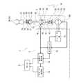
図1に、本発明の一実施形態に係る液圧鉗子システム1を示す。この液圧鉗子システム1は、ロボット鉗子2と制御装置7とモニタ8を含む。 FIG. 1 shows a
本実施形態では、液圧鉗子システム1が手術支援ロボットに用いられる。このため、ロボット鉗子2がスレーブ側装置のマニピュレータ10に取り付けられ、マスタ側装置で医師により遠隔操作される。モニタ8は、そのマスタ側装置に組み込まれる。制御装置7は、マスタ側装置に搭載されてもよいし、スレーブ側装置に搭載されてもよい。あるいは、制御装置7は、ロボット鉗子2の後述する駆動ユニット21に組み込まれてもよい。 In this embodiment, the
マニピュレータ10は、患者の皮膚に設けられた穴が支点となるようにロボット鉗子2の姿勢を自在に変更する多関節ロボットである。 The
ロボット鉗子2は、作動液20の液圧を利用してグリッパー24の開閉を行うものである。作動液20は、特に限定されるものではないが、例えば、生理食塩水や油などである。 The
具体的に、ロボット鉗子2は、駆動ユニット21と、駆動ユニット21から延びて患者の体内に挿入される挿入シャフト22と、挿入シャフト22の先端に設けられた、一対の爪25からなるグリッパー24を含む。なお、図示は省略するが、駆動ユニット21には、挿入シャフト22をその軸方向にスライドさせる機構、および挿入シャフト22をその中心軸回りに回転させる機構が組み込まれてもよい。さらに、挿入シャフト22の先端部が揺動可能に構成され、その先端部を揺動させる機構が駆動ユニット21に組み込まれてもよい。 Specifically, the
本実施形態では、挿入シャフト22が、直線状に延びる高剛性の管である。ただし、挿入シャフト22は、フレキシブルな管であってもよい。 In this embodiment, the insertion shaft 22 is a high-rigidity tube that extends linearly. However, the insertion shaft 22 may be a flexible tube.
挿入シャフト22の先端部内には、第1シリンダ31が配置されている。本実施形態では、第1シリンダ31の中心軸が挿入シャフト22の中心軸と一致している。第1シリンダ31は、管状部と、管状部の内部をグリッパー24側から閉塞する前壁と、管状部の内部をグリッパー24と反対側から閉塞する後壁を有している。 A
第1シリンダ31内には、第1ピストン32が収容されている。第1ピストン32の外周面には、当該外周面と第1シリンダ31の管状部の内周面との間をシールするためのシール部材35が装着されている。第1ピストン32と第1シリンダ31の後壁との間には第1圧力室3Aが形成され、第1ピストン32と第1シリンダ31の前壁との間には背圧室3Bが形成されている。第1圧力室3A内は作動液20で満たされており、背圧室3B内は大気中に開放されている。本実施形態では、背圧室3B内に、第1ピストン32を付勢するスプリング34が配置されている。 A first piston 32 is accommodated in the
第1ピストン32は、第1シリンダ31の前壁を貫通するロッド33によりリンク機構23を介してグリッパー24と連結されている。リンク機構23は、ロッド33の直線運動をグリッパー24の開閉運動に変換する。 The first piston 32 is connected to the
駆動ユニット21内には、連通路26により第1シリンダ31と接続された第2シリンダ41が配置されている。本実施形態では、第2シリンダ41の軸方向が、挿入シャフト22の軸方向と平行である。ただし、第2シリンダ41の軸方向は、特に限定されるものではない。第2シリンダ41は、管状部と、管状部の内部を挿入シャフト22側から閉塞する前壁と、管状部の内部を挿入シャフト22と反対側から閉塞する後壁を有している。 A
第2シリンダ41内には、第2ピストン42が収容されている。第2ピストン42の外周面には、当該外周面と第2シリンダ41の管状部の内周面との間をシールするためのシール部材45が装着されている。第2ピストン42と第2シリンダ41の前壁との間には第2圧力室4Aが形成され、第2ピストン42と第2シリンダ41の後壁との間には背圧室4Bが形成されている。第2圧力室4A内は作動液20で満たされており、背圧室4B内は大気中に開放されている。 A
上述した連通路26は、挿入シャフト22内を延びており、第1圧力室3Aと第2圧力室4Aとを連通している。この連通路26内も作動液20で満たされている。例えば、連通路26は、金属製の管または樹脂製のフレキシブルなチューブで構成される。 The
第2ピストン42は、第2シリンダ41の後壁を貫通するロッド43により直動機構51と連結されている。直動機構51は、モータ52の出力シャフト53とも連結されている。直動機構51は、モータ52の出力シャフト53の回転運動をロッド43の直線運動に変換する。つまり、モータ52は、直動機構51およびロッド43を介して第2ピストン42を駆動する。モータ52は、例えばサーボモータである。 The
モータ52の一方向への回転によって第2ピストン42が前進すると、作動液20が第2圧力室4Aから第1圧力室3Aへ供給されて第1ピストン32がスプリング34の付勢力に抗して前進する。一方、モータ52の逆方向への回転によって第2ピストン42が後退すると、スプリング34の付勢力によって第1ピストン32が後退しながら作動液20が第1圧力室3Aから第2圧力室4Aへ排出される。すなわち、第2シリンダ41、第2ピストン42、直動機構51およびモータ52は、第1圧力室3Aに対する作動液給排機構を構成する。 When the
制御装置7は、上述したマスタ側装置におけるグリッパー開閉操作に基づいてモータ52を制御する。制御装置7は、例えば、ROMやRAMなどのメモリとCPUからなり、ROMに格納されたプログラムがCPUにより実行される。具体的に、制御装置7は、インバータ部71およびオブザーバ72を含む。制御装置7は、単一の機器であってもよいし、複数の機器に分割されてもよい。 The
本実施形態では、制御装置7が、圧力センサ61および位置センサ62と電気的に接続されている。圧力センサ61は、作動液20の圧力Pを検出するものであり、位置センサ62は、第2ピストン42の位置x2の検出に用いられるものである。In the present embodiment, the
本実施形態では、位置センサ62が、モータ52に設けられたロータリエンコーダであり、モータ52の回転変位量を検出し、その回転変位量を第2ピストン42の位置x2に変換する。ただし、位置センサ62は、直動機構51に設けられたリニアエンコーダであってもよいし、第2シリンダ41に設けられて第2ピストン42の位置x2を直接的に検出してもよい。In the present embodiment, the
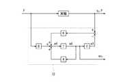
オブザーバ72は、圧力センサ61で検出される作動液20の圧力Pおよび位置センサ62を用いて検出される第2ピストン42の位置x2に基づいて、第1ピストン32の推定位置ex1を導出する。図2に示すように、オブザーバ72は、第2ピストン42に力Fを加えたときの第2ピストン42および第1ピストン32の移動量をモデル化したものであり、以下の状態方程式1および出力方程式2で示すことができる。なお、以下では、ニュートンの記法に従って変数の上に記すべきドット記号を変数の右上に記す。The
X・=AX+BF ・・・(1)
Y=CX ・・・(2)
X・,X,Y:図3に示す行列で表される状態変数
x1:第1ピストンの位置
x2:第2ピストンの位置
P:作動液の圧力
F:第2ピストンに加えられる力
A、B:状態方程式1中の係数を示す行列
C:出力方程式2中の係数を示す行列
行列A,Bは、第1ピストン32に関する状態方程式および第2ピストン42に関する状態方程式などから求められる。X· = AX + BF (1)
Y = CX (2)
X·, X, Y: the state variable represented by a matrix shown in FIG. 3
x1 : position of the first piston
x2 : position of the second piston
P: pressure of hydraulic fluid F: force applied to the second piston A, B: matrix indicating coefficients in the state equation 1 C: matrix matrices A and B indicating coefficients in the
より詳しくは、オブザーバ72は、まず行列A,Bを用いて推定状態変数eX・を求め、ついでこれを積分して推定状態変数eXを算出する。つまり、オブザーバ72は、第1ピストン32の推定位置ex1だけでなく、第2ピストン42の推定位置ex2および作動液20の推定圧力ePも導出する。More specifically, the
さらに、オブザーバ72は、行列Cを用いて第2ピストン42の推定位置ex2および作動液20の推定圧力ePを抜き出し、それらを位置センサ62を用いて検出される第2ピストン42の位置x2および圧力センサ61で検出される作動液20の圧力Pと比較する。そして、オブザーバ72は、第2ピストン42の検出された位置x2と推定位置ex2との偏差Δx2(=x2−ex2)と、作動液20の検出された圧力Pと推定圧力ePとの偏差ΔP(=P−eP)とに基づき、行列Kを用いて状態変数X・の全要素についての推定誤差を算出する。その後、オブザーバ72は、算出した推定誤差を推定状態変数eX・の演算にフィードバックする。換言すれば、推定誤差は、第1ピストン32の推定位置ex1の導出にフォードバックされる。Further, the
インバータ部71は、オブザーバ72により導出される第1ピストン32の推定位置ex1が、マスタ側装置におけるグリッパー開閉操作に基づく指令位置となるように、モータ52へ電力を供給する。The
さらに、本実施形態では、制御装置7が、圧力センサ61で検出される作動液20の圧力Pおよび位置センサ62を用いて検出される第2ピストン42の位置x2に基づいて、グリッパー24の現在把持力Fcを算出する。具体的に、制御装置7は、インバータ部71およびオブザーバ72に加えて、把持力算出部73およびアラーム表示部74を含む。Furthermore, in this embodiment, the
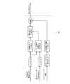
把持力算出部73は、圧力センサ61で検出される作動液20の圧力Pおよびオブザーバ72により導出される第1ピストン32の推定位置ex1に基づいて、現在把持力Fcを算出する。Gripping
より詳しくは、図4に示すように、把持力算出部73は、まず、圧力センサ61で検出される作動液20の圧力P(本実施形態では、フィルタをかけた後の圧力P’)から理論把持力F1を算出する。理論把持力F1は、例えば以下の式により算出される。 More specifically, as shown in FIG. 4, the gripping
F1=A1×P’×β
A1:第1ピストンの面積
β:グリッパーのレバー比
また、把持力算出部73は、第1ピストン32の推定位置ex1および圧力センサ61で検出される作動液20の圧力P(本実施形態では、フィルタをかけた後の圧力P’)から第1ピストン32と第1シリンダ31との間のシール部材35の摩擦力Fdを算出する。例えば、制御装置7のメモリには、作動液20の圧力Pおよび第1ピストン32の位置x1とシール部材35の摩擦力Fdとの関係を示す試験データがテーブルとして予め格納され、このテーブルを使用して摩擦力Fdが算出される。F1 = A1 × P ′ × β
A1: the area of the first piston beta: lever ratio of the gripper also grip
その後、把持力算出部73は、理論把持力F1からシール部材35の摩擦力Fdを差し引いて推定把持力F2を算出する(F2=F1−Fd)。さらに、把持力算出部73は、ロボット鉗子2の姿勢によって推定把持力F2を補正して現在把持力Fcを算出する。具体的には、推定把持力F2に補正係数αを掛けて現在把持力Fcを算出する。 Thereafter, the gripping
補正係数αに関してより詳しく説明すると、把持力算出部73は、マニピュレータ10からロボット鉗子2の姿勢に関する情報を入手してロボット鉗子2の姿勢を計算し、その姿勢から補正係数αを算出する。例えば、補正係数αは、把持した物の重力による把持方向の反力などの影響を表す。 Explaining in more detail about the correction coefficient α, the gripping
算出された現在把持力Fcは、把持力算出部73からモニタ8に送信される。モニタ8は、図5に示すように、患者の体内の画像と共に、現在把持力Fcを表示する。図5に示す例では、現在把持力Fcが把持力スケール内のマークで表示されているが、現在把持力Fcは、例えば数値のみで表示されてもよい。 The calculated current gripping force Fc is transmitted from the gripping
さらに、把持力算出部73で算出された現在把持力Fcは、アラーム表示部74にも送信される。アラーム表示部74は、現在把持力Fcが閾値γを上回るときにモニタ8にアラームを表示する。閾値γは、グリッパー24の種類および手術対象である臓器の種類ごとに定められていることが望ましい。 Further, the current gripping force Fc calculated by the gripping
以上説明したように、本実施形態の液圧鉗子システム1では、制御装置7で算出された現在把持力Fcがモニタ8に表示されるので、ロボット鉗子2を操作する医師にグリッパー24の現在の把持力を提示することができる。 As described above, in the
また、本実施形態では、把持力算出部73がオブザーバ72により導出された第1ピストンの推定位置ex1に基づいて現在把持力Fcを算出するので、ロボット鉗子2の先端部に位置センサを設けることなく、第1ピストン32の位置を加味してグリッパー24の現在把持力Fcを算出することができる。Further, in the present embodiment, since the calculated current gripping force Fc based on the estimated position ex1 the first piston gripping
さらに、本実施形態では、把持力算出部73が第1ピストン32と第1シリンダ31との間のシール部材35の摩擦力Fdを算出し、これを使用して推定把持力F2を算出するので、その摩擦力Fdを加味して推定把持力F2を算出することができる。 Furthermore, in the present embodiment, the gripping
また、把持力算出部73は、ロボット鉗子2の姿勢によって推定把持力F2を補正して現在把持力Fcを算出するので、ロボット鉗子2の姿勢を加味して現在把持力Fcを算出することができる。 Further, since the gripping
さらに、制御装置7はアラーム表示部74を含むので、グリッパー24の把持力が危険となったことを医師に瞬時に把握させることができる。 Furthermore, since the
(変形例)
本発明は上述した実施形態に限定されるものではなく、本発明の要旨を逸脱しない範囲で種々の変形が可能である。(Modification)
The present invention is not limited to the above-described embodiments, and various modifications can be made without departing from the gist of the present invention.
例えば、第1ピストン32の推定位置ex1を導出するオブザーバ72の代わりに、第1ピストン32の位置x1を直接的に検出する位置センサが第1シリンダ31に設けられてもよい。For example, a position sensor that directly detects the position x1 of the first piston 32 may be provided in the
あるいは、制御装置7は、位置センサ62を用いて検出される第2ピストン42の位置x2に基づかず、圧力センサ61で検出される圧力のみに基づいて、グリッパー24の現在把持力Fcを算出してもよい。Alternatively, the
また、前記実施形態では、推定把持力F2が補正されて現在把持力Fcが算出されているが、ロボット鉗子2の姿勢があまり変化しない場合には、推定把持力F2をそのまま現在把持力Fcとしてもよい。 In the embodiment, the estimated gripping force F2 is corrected and the current gripping force Fc is calculated. However, if the posture of the
また、現在把持力Fcの算出時に、シール部材35の摩擦力Fdだけでなく、第2ピストン42と第2シリンダ41との間のシール部材45の摩擦力も考慮してもよい。 Further, when calculating the current gripping force Fc, not only the frictional force Fd of the
また、ロボット鉗子2は、モータ52を内蔵せずに手動で操作されてもよい。この場合、モニタ8は、患者の脇に立つ位置が視認できるように手術室内に独立して設置されてもよい。 The
また、前記実施形態では、スプリング34の付勢力によって第1ピストン32が後退する。しかし、第2シリンダ41、第2ピストン42、直動機構51およびモータ52を含む作動液給排機構がもう1つ設けられるとともに、もう1つの作動液給排機構の第2圧力室4Aが第1シリンダ31の前壁と第1ピストン32の間の背圧室3Bと接続されて、背圧室3Bに供給される作動液の液圧によって第1ピストン32が後退してもよい。あるいは、第1ピストン32にワイヤの一端が固定され、ワイヤの引っ張りによって第1ピストン32が後退してもよい。 In the embodiment, the first piston 32 moves backward by the biasing force of the
また、オブザーバ72に対して、第1ピストン32および/または第2ピストン42の状態、負荷条件、ロボット鉗子2の個体差、周辺環境などに応じて補正をかけることを可能とする手段が別途設けられてもよい。 In addition, a means for allowing correction to the
1 液圧鉗子システム
2 ロボット鉗子
20 作動液
24 グリッパー
31 第1シリンダ
32 第1ピストン
3A 第1圧力室
35,45 シール部材
41 第2シリンダ
42 第2ピストン
4A 第2圧力室
51 直動機構
52 モータ
61 圧力センサ
62 位置センサ
7 制御装置
72 オブザーバ
73 把持力算出部
74 アラーム表示部
8 モニタ
DESCRIPTION OF
Claims (6)
Translated fromJapanese前記作動液の圧力を検出する圧力センサと、
前記圧力センサで検出される前記作動液の圧力に基づいて前記グリッパーの現在把持力を算出する制御装置と、
前記現在把持力を表示するモニタと、
を備える、液圧鉗子システム。Robot forceps that opens and closes the gripper using the hydraulic pressure of the hydraulic fluid,
A pressure sensor for detecting the pressure of the hydraulic fluid;
A control device for calculating a current gripping force of the gripper based on the pressure of the hydraulic fluid detected by the pressure sensor;
A monitor for displaying the current gripping force;
A hydraulic forceps system comprising:
前記第2ピストンの位置の検出に用いられる位置センサをさらに備え、
前記制御装置は、前記圧力センサで検出される前記作動液の圧力および前記位置センサを用いて検出される前記第2ピストンの位置に基づいて前記第1ピストンの推定位置を導出するオブザーバと、前記第1ピストンの推定位置および前記圧力センサで検出される前記作動液の圧力に基づいて前記現在把持力を算出する把持力算出部を含む、請求項1または2に記載の液圧鉗子システム。The robot forceps includes a first piston connected to the gripper, a first cylinder that houses the first piston and forms a first pressure chamber filled with the hydraulic fluid together with the first piston, the second piston, A second cylinder that houses the second piston and forms a second pressure chamber filled with the hydraulic fluid together with the second piston, a communication path that communicates the first pressure chamber and the second pressure chamber, and linear motion A motor for driving the second piston via a mechanism,
A position sensor used for detecting the position of the second piston;
The control device includes: an observer for deriving an estimated position of the first piston based on a pressure of the hydraulic fluid detected by the pressure sensor and a position of the second piston detected using the position sensor; 3. The hydraulic forceps system according to claim 1, further comprising a gripping force calculation unit that calculates the current gripping force based on an estimated position of the first piston and a pressure of the hydraulic fluid detected by the pressure sensor.
Priority Applications (5)
| Application Number | Priority Date | Filing Date | Title |
|---|---|---|---|
| JP2016252569AJP6577936B2 (en) | 2016-12-27 | 2016-12-27 | Hydraulic forceps system |
| PCT/JP2017/045659WO2018123754A1 (en) | 2016-12-27 | 2017-12-20 | Hydraulic forceps system |
| US16/474,259US11147575B2 (en) | 2016-12-27 | 2017-12-20 | Hydraulic forceps system |
| CN201780079307.7ACN110072485B (en) | 2016-12-27 | 2017-12-20 | Hydraulic clamp system |
| EP17888999.4AEP3563791B1 (en) | 2016-12-27 | 2017-12-20 | Hydraulic forceps system |
Applications Claiming Priority (1)
| Application Number | Priority Date | Filing Date | Title |
|---|---|---|---|
| JP2016252569AJP6577936B2 (en) | 2016-12-27 | 2016-12-27 | Hydraulic forceps system |
Publications (2)
| Publication Number | Publication Date |
|---|---|
| JP2018102634Atrue JP2018102634A (en) | 2018-07-05 |
| JP6577936B2 JP6577936B2 (en) | 2019-09-18 |
Family
ID=62711041
Family Applications (1)
| Application Number | Title | Priority Date | Filing Date |
|---|---|---|---|
| JP2016252569AActiveJP6577936B2 (en) | 2016-12-27 | 2016-12-27 | Hydraulic forceps system |
Country Status (5)
| Country | Link |
|---|---|
| US (1) | US11147575B2 (en) |
| EP (1) | EP3563791B1 (en) |
| JP (1) | JP6577936B2 (en) |
| CN (1) | CN110072485B (en) |
| WO (1) | WO2018123754A1 (en) |
Cited By (5)
| Publication number | Priority date | Publication date | Assignee | Title |
|---|---|---|---|---|
| CN110537894A (en)* | 2019-10-14 | 2019-12-06 | 南京市第一医院 | Capsule gastroscope with biopsy function |
| CN111227910A (en)* | 2020-03-06 | 2020-06-05 | 杨红伟 | Alimentary canal minimal access surgery tissue pincers |
| JPWO2021066122A1 (en)* | 2019-10-04 | 2021-04-08 | ||
| JP2021126233A (en)* | 2020-02-12 | 2021-09-02 | リバーフィールド株式会社 | Surgical robot |
| CN117064496A (en)* | 2023-09-11 | 2023-11-17 | 南京道壹生物医学科技有限公司 | Laparoscopic forceps with monitoring sensor and high-precision pressure monitoring method |
Families Citing this family (7)
| Publication number | Priority date | Publication date | Assignee | Title |
|---|---|---|---|---|
| JP6577936B2 (en)* | 2016-12-27 | 2019-09-18 | 川崎重工業株式会社 | Hydraulic forceps system |
| CN111096774B (en)* | 2020-02-25 | 2020-08-14 | 青岛大学附属医院 | Minimally invasive surgical tissue clamp |
| CN111150453B (en)* | 2020-02-25 | 2020-10-13 | 时建 | Minimally invasive surgery clamp |
| CN111331620B (en)* | 2020-04-03 | 2021-01-22 | 福鼎中重特种机器人有限公司 | Mechanical arm of fire-fighting robot |
| CN111388070B (en)* | 2020-04-07 | 2020-12-15 | 中南大学湘雅二医院 | An elastic forceps for obstetrics and gynecology |
| US11644101B2 (en)* | 2020-06-04 | 2023-05-09 | Alton Reich | Seal inflation/deflation apparatus and method of use thereof |
| CN114831736B (en)* | 2022-04-15 | 2023-10-20 | 江苏唯德康医疗科技有限公司 | Clamping instrument with force feedback for natural cavity tract operation |
Citations (5)
| Publication number | Priority date | Publication date | Assignee | Title |
|---|---|---|---|---|
| JP2002253574A (en)* | 2001-03-01 | 2002-09-10 | Hitachi Ltd | Surgery support device |
| JP2003039370A (en)* | 2001-07-24 | 2003-02-13 | Aloka Co Ltd | Handling device |
| JP2013517898A (en)* | 2010-01-26 | 2013-05-20 | ケアフュージョン2200、インコーポレイテッド | Powered signal control manual joint device and method of use |
| US20140330073A1 (en)* | 2012-05-15 | 2014-11-06 | Samsung Electronics Co., Ltd. | End effector and remote control apparatus |
| JP2015024142A (en)* | 2007-07-12 | 2015-02-05 | ボード オブ リージェンツ オブ ザ ユニバーシティ オブ ネブラスカ | Robotic surgical system |
Family Cites Families (24)
| Publication number | Priority date | Publication date | Assignee | Title |
|---|---|---|---|---|
| JPH0747017B2 (en) | 1986-12-25 | 1995-05-24 | 富士写真光機株式会社 | Endoscope |
| US4848338A (en)* | 1987-01-20 | 1989-07-18 | Minnesota Mining And Manufacturing Company | Hydraulically operated surgical instrument |
| US5250074A (en)* | 1992-07-14 | 1993-10-05 | Wilk Peter J | Surgical instrument assembly and associated technique |
| US5791231A (en)* | 1993-05-17 | 1998-08-11 | Endorobotics Corporation | Surgical robotic system and hydraulic actuator therefor |
| US5720742A (en)* | 1994-10-11 | 1998-02-24 | Zacharias; Jaime | Controller and actuating system for surgical instrument |
| US5624398A (en)* | 1996-02-08 | 1997-04-29 | Symbiosis Corporation | Endoscopic robotic surgical tools and methods |
| US20100241137A1 (en)* | 2000-07-20 | 2010-09-23 | Mark Doyle | Hand-actuated articulating surgical tool |
| US8241228B1 (en)* | 2003-09-24 | 2012-08-14 | Microfabrica Inc. | Micro-scale and meso-scale hydraulic and pneumatic tools, methods for using, and methods for making |
| WO2004028585A2 (en) | 2002-09-30 | 2004-04-08 | Sightline Technologies Ltd. | Piston-actuated endoscopic tool |
| US7559452B2 (en)* | 2005-02-18 | 2009-07-14 | Ethicon Endo-Surgery, Inc. | Surgical instrument having fluid actuated opposing jaws |
| EP2040635A1 (en)* | 2006-06-14 | 2009-04-01 | MacDonald Dettwiler & Associates Inc. | Surgical manipulator with right-angle pulley drive mechanisms |
| US20100069953A1 (en)* | 2008-09-16 | 2010-03-18 | Tyco Healthcare Group Lp | Method of Transferring Force Using Flexible Fluid-Filled Tubing in an Articulating Surgical Instrument |
| US8594841B2 (en)* | 2008-12-31 | 2013-11-26 | Intuitive Surgical Operations, Inc. | Visual force feedback in a minimally invasive surgical procedure |
| US8114122B2 (en)* | 2009-01-13 | 2012-02-14 | Tyco Healthcare Group Lp | Apparatus, system, and method for performing an electrosurgical procedure |
| EP2305144B1 (en)* | 2009-03-24 | 2012-10-31 | Olympus Medical Systems Corp. | Robot system for endoscope treatment |
| US20100331879A1 (en)* | 2009-06-25 | 2010-12-30 | The Curators Of The University Of Missouri | Articulating Surgical Hand Tool |
| EP2486287B1 (en)* | 2009-10-07 | 2015-05-13 | Simon Fraser University | Fluidic actuator and method of manufacture |
| WO2012097342A1 (en)* | 2011-01-14 | 2012-07-19 | Transenterix, Inc. | Surgical stapling device and method |
| US9808317B2 (en)* | 2012-01-09 | 2017-11-07 | Covidien Lp | Pneumatic system for deployment of articulating arms for an access port |
| JP6159075B2 (en) | 2012-11-01 | 2017-07-05 | 国立大学法人東京工業大学 | Forceps manipulator and forceps system including forceps manipulator |
| WO2015025745A1 (en)* | 2013-08-21 | 2015-02-26 | オリンパスメディカルシステムズ株式会社 | Treatment tool and treatment system |
| JP6550368B2 (en)* | 2016-12-27 | 2019-07-24 | 川崎重工業株式会社 | Hydraulic insulator system |
| JP6577936B2 (en)* | 2016-12-27 | 2019-09-18 | 川崎重工業株式会社 | Hydraulic forceps system |
| JP6646570B2 (en)* | 2016-12-28 | 2020-02-14 | 川崎重工業株式会社 | Robot forceps |
- 2016
- 2016-12-27JPJP2016252569Apatent/JP6577936B2/enactiveActive
- 2017
- 2017-12-20WOPCT/JP2017/045659patent/WO2018123754A1/ennot_activeCeased
- 2017-12-20USUS16/474,259patent/US11147575B2/enactiveActive
- 2017-12-20CNCN201780079307.7Apatent/CN110072485B/ennot_activeExpired - Fee Related
- 2017-12-20EPEP17888999.4Apatent/EP3563791B1/enactiveActive
Patent Citations (5)
| Publication number | Priority date | Publication date | Assignee | Title |
|---|---|---|---|---|
| JP2002253574A (en)* | 2001-03-01 | 2002-09-10 | Hitachi Ltd | Surgery support device |
| JP2003039370A (en)* | 2001-07-24 | 2003-02-13 | Aloka Co Ltd | Handling device |
| JP2015024142A (en)* | 2007-07-12 | 2015-02-05 | ボード オブ リージェンツ オブ ザ ユニバーシティ オブ ネブラスカ | Robotic surgical system |
| JP2013517898A (en)* | 2010-01-26 | 2013-05-20 | ケアフュージョン2200、インコーポレイテッド | Powered signal control manual joint device and method of use |
| US20140330073A1 (en)* | 2012-05-15 | 2014-11-06 | Samsung Electronics Co., Ltd. | End effector and remote control apparatus |
Cited By (10)
| Publication number | Priority date | Publication date | Assignee | Title |
|---|---|---|---|---|
| JPWO2021066122A1 (en)* | 2019-10-04 | 2021-04-08 | ||
| US12426981B2 (en) | 2019-10-04 | 2025-09-30 | National University Corporation Kagawa University | Grip tool, grip system, slip detection device, slip detection program, and slip detection method |
| CN110537894A (en)* | 2019-10-14 | 2019-12-06 | 南京市第一医院 | Capsule gastroscope with biopsy function |
| CN110537894B (en)* | 2019-10-14 | 2021-05-07 | 南京市第一医院 | Capsule gastroscope with biopsy function |
| JP2021126233A (en)* | 2020-02-12 | 2021-09-02 | リバーフィールド株式会社 | Surgical robot |
| CN115087411A (en)* | 2020-02-12 | 2022-09-20 | 瑞德医疗机器股份有限公司 | Robot for operation |
| US12357402B2 (en) | 2020-02-12 | 2025-07-15 | Riverfield Inc. | Surgical robot |
| CN111227910A (en)* | 2020-03-06 | 2020-06-05 | 杨红伟 | Alimentary canal minimal access surgery tissue pincers |
| CN111227910B (en)* | 2020-03-06 | 2020-12-15 | 王光铭 | Alimentary canal minimal access surgery tissue pincers |
| CN117064496A (en)* | 2023-09-11 | 2023-11-17 | 南京道壹生物医学科技有限公司 | Laparoscopic forceps with monitoring sensor and high-precision pressure monitoring method |
Also Published As
| Publication number | Publication date |
|---|---|
| CN110072485A (en) | 2019-07-30 |
| EP3563791A1 (en) | 2019-11-06 |
| JP6577936B2 (en) | 2019-09-18 |
| US11147575B2 (en) | 2021-10-19 |
| US20200121341A1 (en) | 2020-04-23 |
| CN110072485B (en) | 2021-12-28 |
| EP3563791A4 (en) | 2020-08-12 |
| WO2018123754A1 (en) | 2018-07-05 |
| EP3563791B1 (en) | 2024-02-28 |
Similar Documents
| Publication | Publication Date | Title |
|---|---|---|
| JP6577936B2 (en) | Hydraulic forceps system | |
| CN110087575B (en) | Hydraulic clamp system | |
| US20230218354A1 (en) | Surgery supporting apparatus for controlling motion of robot arm | |
| JP5754820B2 (en) | Surgical robot | |
| JP6931420B2 (en) | Surgical robot system | |
| RU2740114C1 (en) | Surgical robot system and surgical instrument for it | |
| JP5085684B2 (en) | Treatment instrument system and manipulator system | |
| CN108210078B (en) | Surgical robot system | |
| CN114554998B (en) | Surgical robot system, external force estimation device, and program | |
| JP2009131374A (en) | Treatment instrument system and manipulator system | |
| KR102221090B1 (en) | User interface device, master console for surgical robot apparatus and operating method of master console | |
| US20180049831A1 (en) | Medical manipulator system | |
| CN117257467B (en) | Endoscope operating force determination device, computer equipment and readable storage medium | |
| KR20150041346A (en) | Method and system for controlling articulated manipulator | |
| JP2022142902A (en) | Force measuring device and force measuring method, surgical device, and surgical system | |
| JP2014197343A (en) | Kinesthetic sense presentation device and method |
Legal Events
| Date | Code | Title | Description |
|---|---|---|---|
| A621 | Written request for application examination | Free format text:JAPANESE INTERMEDIATE CODE: A621 Effective date:20180807 | |
| A131 | Notification of reasons for refusal | Free format text:JAPANESE INTERMEDIATE CODE: A131 Effective date:20190604 | |
| A521 | Request for written amendment filed | Free format text:JAPANESE INTERMEDIATE CODE: A523 Effective date:20190712 | |
| TRDD | Decision of grant or rejection written | ||
| A01 | Written decision to grant a patent or to grant a registration (utility model) | Free format text:JAPANESE INTERMEDIATE CODE: A01 Effective date:20190730 | |
| A61 | First payment of annual fees (during grant procedure) | Free format text:JAPANESE INTERMEDIATE CODE: A61 Effective date:20190823 | |
| R150 | Certificate of patent or registration of utility model | Ref document number:6577936 Country of ref document:JP Free format text:JAPANESE INTERMEDIATE CODE: R150 | |
| R250 | Receipt of annual fees | Free format text:JAPANESE INTERMEDIATE CODE: R250 | |
| R250 | Receipt of annual fees | Free format text:JAPANESE INTERMEDIATE CODE: R250 | |
| R250 | Receipt of annual fees | Free format text:JAPANESE INTERMEDIATE CODE: R250 |