JP2018098571A - Wearable camera - Google Patents
Wearable cameraDownload PDFInfo
- Publication number
- JP2018098571A JP2018098571AJP2016239626AJP2016239626AJP2018098571AJP 2018098571 AJP2018098571 AJP 2018098571AJP 2016239626 AJP2016239626 AJP 2016239626AJP 2016239626 AJP2016239626 AJP 2016239626AJP 2018098571 AJP2018098571 AJP 2018098571A
- Authority
- JP
- Japan
- Prior art keywords
- housing
- wearable camera
- holding member
- mounting surface
- magnet
- Prior art date
- Legal status (The legal status is an assumption and is not a legal conclusion. Google has not performed a legal analysis and makes no representation as to the accuracy of the status listed.)
- Pending
Links
Images


Classifications
- H—ELECTRICITY
- H04—ELECTRIC COMMUNICATION TECHNIQUE
- H04N—PICTORIAL COMMUNICATION, e.g. TELEVISION
- H04N23/00—Cameras or camera modules comprising electronic image sensors; Control thereof
- H04N23/50—Constructional details
- H04N23/51—Housings
- H—ELECTRICITY
- H04—ELECTRIC COMMUNICATION TECHNIQUE
- H04N—PICTORIAL COMMUNICATION, e.g. TELEVISION
- H04N7/00—Television systems
- H04N7/18—Closed-circuit television [CCTV] systems, i.e. systems in which the video signal is not broadcast
- H04N7/183—Closed-circuit television [CCTV] systems, i.e. systems in which the video signal is not broadcast for receiving images from a single remote source
- F—MECHANICAL ENGINEERING; LIGHTING; HEATING; WEAPONS; BLASTING
- F16—ENGINEERING ELEMENTS AND UNITS; GENERAL MEASURES FOR PRODUCING AND MAINTAINING EFFECTIVE FUNCTIONING OF MACHINES OR INSTALLATIONS; THERMAL INSULATION IN GENERAL
- F16M—FRAMES, CASINGS OR BEDS OF ENGINES, MACHINES OR APPARATUS, NOT SPECIFIC TO ENGINES, MACHINES OR APPARATUS PROVIDED FOR ELSEWHERE; STANDS; SUPPORTS
- F16M13/00—Other supports for positioning apparatus or articles; Means for steadying hand-held apparatus or articles
- F16M13/04—Other supports for positioning apparatus or articles; Means for steadying hand-held apparatus or articles for supporting on, or holding steady relative to, a person, e.g. by chains, e.g. rifle butt or pistol grip supports, supports attached to the chest or head
- G—PHYSICS
- G03—PHOTOGRAPHY; CINEMATOGRAPHY; ANALOGOUS TECHNIQUES USING WAVES OTHER THAN OPTICAL WAVES; ELECTROGRAPHY; HOLOGRAPHY
- G03B—APPARATUS OR ARRANGEMENTS FOR TAKING PHOTOGRAPHS OR FOR PROJECTING OR VIEWING THEM; APPARATUS OR ARRANGEMENTS EMPLOYING ANALOGOUS TECHNIQUES USING WAVES OTHER THAN OPTICAL WAVES; ACCESSORIES THEREFOR
- G03B17/00—Details of cameras or camera bodies; Accessories therefor
- G03B17/56—Accessories
- G03B17/561—Support related camera accessories
- H—ELECTRICITY
- H04—ELECTRIC COMMUNICATION TECHNIQUE
- H04N—PICTORIAL COMMUNICATION, e.g. TELEVISION
- H04N7/00—Television systems
- H04N7/18—Closed-circuit television [CCTV] systems, i.e. systems in which the video signal is not broadcast
- H—ELECTRICITY
- H04—ELECTRIC COMMUNICATION TECHNIQUE
- H04N—PICTORIAL COMMUNICATION, e.g. TELEVISION
- H04N7/00—Television systems
- H04N7/18—Closed-circuit television [CCTV] systems, i.e. systems in which the video signal is not broadcast
- H04N7/183—Closed-circuit television [CCTV] systems, i.e. systems in which the video signal is not broadcast for receiving images from a single remote source
- H04N7/185—Closed-circuit television [CCTV] systems, i.e. systems in which the video signal is not broadcast for receiving images from a single remote source from a mobile camera, e.g. for remote control
- G—PHYSICS
- G03—PHOTOGRAPHY; CINEMATOGRAPHY; ANALOGOUS TECHNIQUES USING WAVES OTHER THAN OPTICAL WAVES; ELECTROGRAPHY; HOLOGRAPHY
- G03B—APPARATUS OR ARRANGEMENTS FOR TAKING PHOTOGRAPHS OR FOR PROJECTING OR VIEWING THEM; APPARATUS OR ARRANGEMENTS EMPLOYING ANALOGOUS TECHNIQUES USING WAVES OTHER THAN OPTICAL WAVES; ACCESSORIES THEREFOR
- G03B2217/00—Details of cameras or camera bodies; Accessories therefor
- G03B2217/002—Details of arrangement of components in or on camera body
- H—ELECTRICITY
- H04—ELECTRIC COMMUNICATION TECHNIQUE
- H04N—PICTORIAL COMMUNICATION, e.g. TELEVISION
- H04N5/00—Details of television systems
- H04N5/76—Television signal recording
- H04N5/765—Interface circuits between an apparatus for recording and another apparatus
- H04N5/77—Interface circuits between an apparatus for recording and another apparatus between a recording apparatus and a television camera
- H04N5/772—Interface circuits between an apparatus for recording and another apparatus between a recording apparatus and a television camera the recording apparatus and the television camera being placed in the same enclosure
Landscapes
- Engineering & Computer Science (AREA)
- Multimedia (AREA)
- Signal Processing (AREA)
- General Engineering & Computer Science (AREA)
- Physics & Mathematics (AREA)
- General Physics & Mathematics (AREA)
- Mechanical Engineering (AREA)
- Studio Devices (AREA)
Abstract
Translated fromJapaneseDescription
Translated fromJapanese本発明は、ユーザの衣服に装着又は保持され、静止画や動画を撮像するウェアラブルカメラに関する。 The present invention relates to a wearable camera that is mounted or held on a user's clothes and captures a still image or a moving image.
例えば警察官や警備員の業務を支援するために使用されるウェアラブルカメラは、警察官の胸部等、ユーザの視点に近い位置からの視野を映像として撮像するように、ユーザが着用した衣服等に装着される(例えば特許文献1参照)。 For example, wearable cameras used to support police officers and guards work on clothes worn by the user, such as the chest of a police officer, so that the field of view from a position close to the user's viewpoint is imaged. Attached (see, for example, Patent Document 1).
また、ウェアラブルカメラは、内蔵される電子部品等の各部に電源を供給するバッテリを筐体内部に収容する。このバッテリは、例えば充電可能な2次電池により構成される。ウェアラブルカメラは、筐体を充電器にセットすることにより、筐体のコンタクトターミナルを充電器の充電接点に接続して充電を行う。 In addition, the wearable camera accommodates a battery that supplies power to each part such as an electronic component incorporated therein. This battery is constituted by a rechargeable secondary battery, for example. The wearable camera is charged by connecting the contact terminal of the casing to the charging contact of the charger by setting the casing on the charger.
しかしながら、特許文献1を含む従来のウェアラブルカメラは、装着した場合の落下防止については考慮されていなかった。特にユーザ(例えば警察官や警備員。但し、これらに限定されないことは言うまでもない。以下同様。)が何らかの理由で走る際、ウェアラブルカメラに作用する慣性による重力方向(下方向)の力は、衣服と筐体とに相対変位(つまり、ずれ落ち)を生じさせ易い。その結果、装着時の状態が維持されない場合がある。ウェアラブルカメラは、装着状態が維持されないと、ユーザにとって所望の画像が得られなかったり、落下して壊れたりする虞がある。 However, the conventional wearable camera including Patent Document 1 does not consider the prevention of falling when the camera is mounted. In particular, when a user (for example, a police officer or a security guard, but not limited to these, the same shall apply hereinafter) runs for some reason, the force in the gravity direction (downward) due to inertia acting on the wearable camera It is easy to cause relative displacement (that is, slip-off) between the housing and the housing. As a result, the state at the time of wearing may not be maintained. If the wearable camera is not maintained in the wearing state, a desired image may not be obtained for the user, or the wearable camera may fall and be broken.
或いは、ウェアラブルカメラには、衣服等への保持性を高めるために筐体背面にクリップをねじ固定するものがある。ところが、クリップ付きウェアラブルカメラは、充電器にセットする際、クリップが邪魔となって充電時に支障が出る。この場合、充電の都度、ねじ固定を解除及び再固定してクリップを筐体から脱着しなければならず、ユーザにとって使い勝手が良くないという問題があった。 Alternatively, there is a wearable camera in which a clip is screwed to the rear surface of the housing in order to improve the holding property to clothes or the like. However, when a wearable camera with a clip is set in a charger, the clip becomes an obstacle and troubles occur during charging. In this case, each time the battery is charged, the fixing of the screw must be released and re-fixed, and the clip must be removed from the housing, which is not convenient for the user.
本発明は、上述した従来の事情に鑑みて案出され、使い勝手を良好にし、しかも、使用時の装着状態から落下防止を抑制することができるウェアラブルカメラを提供することを目的とする。 The present invention has been devised in view of the above-described conventional circumstances, and an object thereof is to provide a wearable camera capable of improving usability and suppressing the fall prevention from the mounted state during use.
本発明は、前面にレンズを表出し、鉛直面に沿う方向の背面が装着側の面となる筐体と、前記背面に形成され、筐体保持部材が着脱自在となる取付面と、前記取付面の上端付近に前記筐体から突出して設けられ、前記取付面に取り付けられた前記筐体保持部材に当接して前記筐体保持部材に対する前記筐体の下方向の移動を規制する突起と、を備える、ウェアラブルカメラを提供する。 The present invention includes a housing in which a lens is exposed on the front surface, and a back surface in a direction along the vertical surface is a mounting side surface, a mounting surface formed on the back surface, and a housing holding member is detachable, and the mounting A protrusion that protrudes from the housing in the vicinity of the upper end of the surface, abuts against the housing holding member attached to the mounting surface, and regulates the downward movement of the housing relative to the housing holding member; A wearable camera is provided.
本発明によれば、ウェアラブルカメラの使用時の使い勝手を良好にし、しかも、使用時の装着状態から落下防止を抑制することができる。 ADVANTAGE OF THE INVENTION According to this invention, the usability at the time of use of a wearable camera can be made favorable, and also fall prevention can be suppressed from the mounting state at the time of use.
以下、適宜図面を参照しながら、本発明に係るウェアラブルカメラを具体的に開示した実施の形態(以下、「本実施の形態」という)を詳細に説明する。但し、必要以上に詳細な説明は省略する場合がある。例えば既によく知られた事項の詳細説明や実質的に同一の構成に対する重複説明を省略する場合がある。これは、以下の説明が不必要に冗長になるのを避け、当業者の理解を容易にするためである。なお、添付図面及び以下の説明は、当業者が本開示を十分に理解するために提供されるのであって、これらにより特許請求の範囲に記載の主題を限定することは意図されていない。 Hereinafter, an embodiment that specifically discloses a wearable camera according to the present invention (hereinafter referred to as “the present embodiment”) will be described in detail with reference to the drawings as appropriate. However, more detailed description than necessary may be omitted. For example, detailed descriptions of already well-known matters and repeated descriptions for substantially the same configuration may be omitted. This is to avoid the following description from becoming unnecessarily redundant and to facilitate understanding by those skilled in the art. The accompanying drawings and the following description are provided to enable those skilled in the art to fully understand the present disclosure, and are not intended to limit the subject matter described in the claims.
図1は、本実施の形態のウェアラブルカメラ100をユーザ(例えば警察官11)が装着した状態の一例を示す模式図である。 FIG. 1 is a schematic diagram illustrating an example of a state in which a
本実施の形態のウェアラブルカメラは、例えばユーザが警察署に勤める警察官がパトロールの時に使用して撮像する場合を想定して説明する。但し、ウェアラブルカメラの使用シーンとして、事件或いは事故が起きた現場に急行した時を想定してもよい。 The wearable camera according to the present embodiment will be described on the assumption that, for example, a police officer who works for a police station uses and takes an image when patroling. However, as a scene where the wearable camera is used, it may be assumed that the wearer camera is rushed to a scene where an incident or accident has occurred.
ウェアラブルカメラ100は、ユーザの一例としての警察官11により使用され、パトロール時に前方の状況を静止画(画像)又は動画(映像)として記憶できるように撮像して蓄積し、例えば警察署内のバックエンドシステムに撮像映像のデータを転送する。なお、ウェアラブルカメラ100は、ユーザが警察官11に限定されず、その他様々な事業所(例えば、警備会社)において使用されてもよい。 The
ウェアラブルカメラ100は、警察官11の胸部等、警察官11の視点に近い位置からの視野を映像として撮像するように、警察官11が着用した衣服(例えば警察官が着用する制服。以下同様。)又は体に装着して使用される。警察官11は、ウェアラブルカメラ100を装着した状態で、録画スイッチSW1を操作して周囲の被写体の撮像を行う。
ウェアラブルカメラ100は、略直方体状の筐体13の前面15に、撮像部を構成する撮像レンズ17、録画スイッチSW1、スナップショットスイッチSW2が設けられる。録画スイッチSW1は、例えば警察官11によって、奇数回押下されることで録画(動画の撮像)が開始され、偶数回押下されることで録画が終了する。スナップショットスイッチSW2は、例えば警察官11によって押下される度に、そのときの静止画の撮像が実行される。 In the
[マグネットタイプ仕様の構成例]
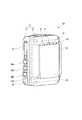
図2は、本実施の形態のウェアラブルカメラ100をマグネットタイプとして用いた場合の背面斜視図である。[Example configuration of magnet type specifications]
FIG. 2 is a rear perspective view when the
本実施の形態に係るウェアラブルカメラ100は、筐体13に、撮像部(図示略)を収容する。筐体13は、前面15に、撮像部を構成する撮像レンズ17を表出する。筐体13は、前面15と反対側の面が、背面19となる。背面19は、鉛直面に沿う方向の面となって、衣服(例えば警察官11が着用する制服)等への装着側の面となる。筐体13は、前面筐体21と、上記の背面19を有する裏蓋23とにより構成される。
なお、ウェアラブルカメラ100の筐体13の正面から見て右側面には、上側より補機接続部25、通信モードスイッチSW3、LED&VibrationスイッチSW4、OFFスイッチSW5等が設けられる。通信モードスイッチSW3は、例えば通信機器(例えば警察署内のバックエンドシステム、パトカー内の車載カメラシステム)との間の通信モードを切り替えるために押下される。LED&VibrationスイッチSW4は、例えばウェアラブルカメラ100の状態を警察官11に報知するために、LED(Light Emission Diode)とバイブレーション(振動)のうちいずれかを切り替えるために押下される。OFFスイッチSW5は、例えばウェアラブルカメラ100の電源をオフするために押下される。 Note that an
筐体13の裏蓋23には、取付面27が形成される。取付面27は、方形状の平坦面となる。この取付面27には、筐体保持部材が、ねじ固定によらずに着脱自在となる。 An
本構成例(つまり、マグネットタイプ仕様)において、ウェアラブルカメラ100における筐体保持部材は、マグネット29である。マグネット29は、取付面27と略同形となった方形の板状に形成される。マグネット29は、例えば衣服のポケット31(図5参照)に入れられる。このため、マグネット29は、安全性を考慮して、例えば着磁されたマグネットゴムとすることが好ましい。 In this configuration example (that is, the magnet type specification), the housing holding member in the
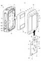
図3は、図2の分解斜視図である。 FIG. 3 is an exploded perspective view of FIG.
前面筐体21は、バッテリ収容部33を有する。バッテリ収容部33には、バッテリ35が収容される。バッテリ35は、例えば充電可能な2次電池により構成される。ウェアラブルカメラ100は、後述するように、筐体13を後述の充電器にセットすることにより、筐体13のコンタクトターミナルを充電器の充電接点に接続して充電を行う。 The
バッテリ35は、取付面27と略同一外形の平らな直方体形状に形成される。バッテリ35は、裏蓋23と対向する面に、略同面積の金属プレート37が両面粘着テープ39等によって固定される。金属プレート37の固定されたバッテリ35は、バッテリ収容部33に配置され、裏蓋23が前面筐体21にねじ固定されることにより、筐体内部に収容される。 The
ウェアラブルカメラ100の裏蓋23が取り付けられると、金属プレート37は取付面27の裏側に近接して配置される。これにより、マグネット29は、裏蓋23を介してマグネット29の磁気吸引力により取付面27に吸着する。このマグネット29の磁気吸引力は、ウェアラブルカメラ100の質量を保持する十分な大きさとなる。 When the
筐体13の裏蓋23には、取付面27の上端付近に近接して突起41が設けられる。本実施の形態において、突起41は、取付面27の左右方向に一対のものが設けられる。突起41は、筐体13の裏蓋23から突出し、取付面27に取り付けられたマグネット29に当接する。筐体13は、マグネット29の上端面に当接することにより、マグネット29に対する下方向の移動が規制される。 A
図4は、図2の背面図である。 4 is a rear view of FIG.
筐体13の裏蓋23には、取付面27を左右から挟める長さを有し、背面19から突出する一対の対向壁部43が設けられる。それぞれの対向壁部43は、平行となって上下方向に延在する。一対の対向壁部43の間隔は、マグネット29の同方向の幅よりも若干大きく設定される。これにより、マグネット29は、ポケット31の生地を挟んで一対の対向壁部43の間に進入可能となっている。つまり、生地を挟んで取付面27に密着したマグネット29は、上端面と、左右側面との三方向が、突起41と、一対の対向壁部43とによって包囲される。 The
次に、上記した構成の作用を説明する。 Next, the operation of the above configuration will be described.
本実施の形態に係るウェアラブルカメラ100では、警察官11の衣服等に設けられた筐体保持部材に対し、筐体13が背面19の取付面27を介して取り付けられる。ウェアラブルカメラ100は、例えば警察官11がパトロール時、又は事件或いは事故の現場で走った際、慣性による重力方向(下方向)の力が大きく作用し、下方向に移動しやすくなる。筐体13は、筐体保持部材に対して下方向に移動しようとすると、取付面27の上端に形成された突起41が、筐体保持部材に当接する。 In the
これにより、筐体13は、取付面27と平行な下方向への移動が規制され、装着時の状態が維持される。その結果、ウェアラブルカメラ100は、画質の劣化を抑制できるとともに、警察官11の使用時の装着状態からの落下防止を抑制できる。 Thereby, the movement of the
また、ウェアラブルカメラ100は、突起41が取付面27の上端に配置されることにより、筐体13の下部を充電器に対し、上方向から挿入する良好な充電操作性を実現している。 In addition, the
このことは、例えば適切な画像が撮れず、撮像画像が後々の用途(例えば検察や裁判所に提出するべき、パトロール中の証拠映像又は現場での証拠映像)に使えないという事態を回避できる。 This avoids a situation in which, for example, an appropriate image cannot be taken and the captured image cannot be used for later use (for example, a patrol evidence video or an on-site evidence video to be submitted to a prosecution or a court).
また、ウェアラブルカメラ100は、筐体保持部材がねじ固定によらずに筐体13の取付面27に対して着脱自在となる。従って、ねじ固定の解除及び再固定を行わずに筐体保持部材の脱着が可能となる。これにより、使用終了時、簡単に充電器と干渉しない状態にでき、容易に充電が行える。 In the
図5は、マグネット29を衣服のポケット31に入れて装着したウェアラブルカメラ100の縦断面図である。 FIG. 5 is a longitudinal sectional view of the
このウェアラブルカメラ100では、マグネット29が衣服の例えばポケット31に入れられ、ポケット31の外側に筐体13の取付面27が当てられる。マグネット29と金属プレート37との間には、磁気吸引力が働く。この磁気吸引力によりマグネット29と取付面27との間に、ポケット31の生地が挟まれ、筐体13が衣服に対して強固に固定可能となる。取り外しの際は、磁気吸引力に抗して警察官11が筐体13を磁気吸引力以上の外力を加えて引き剥がせば、ウェアラブルカメラ100の簡単な取り外しが可能となる。その際、マグネット29は、ポケット内に落下して保持される。取り外されたウェアラブルカメラ100は、取付面27に筐体保持部材が残らず、そのまま充電器へのセットが可能となる。 In this
また、このウェアラブルカメラ100では、筐体保持部材(例えばマグネット29)が、取付面27の左右に突設された一対の対向壁部43によっても挟まれる。これにより、筐体13とマグネット29とは、突起41、一対の対向壁部43の三箇所で当接し、取付面27に垂直な軸回りの相対回転を規制することが可能となる。 Further, in the
[クリップタイプ仕様の構成例]
図6は、本実施の形態のウェアラブルカメラ100をクリップタイプとして用いた場合の背面斜視図である。[Configuration example of clip type specifications]
FIG. 6 is a rear perspective view when the
本実施の形態のウェアラブルカメラ100は、マグネットタイプに限定されず、例えばクリップタイプとしても使用することができる。ウェアラブルカメラ100は、マグネットタイプと同一のものが使用できる。すなわち、ウェアラブルカメラ100は、マグネット29の替わりに、筐体保持部材であるクリップが使用できる兼用構造を有する。
ウェアラブルカメラ100は、取付面27に、クリップを固定するプレート45が、着脱自在となる。プレート45は、一対の対向壁部43の間隔よりも、同方向の大きさが若干大きく形成される。このプレート45は、例えば金属又は樹脂により形成される。 In the
図7は、図6の分解斜視図である。 FIG. 7 is an exploded perspective view of FIG.
一対の対向壁部43の対向面には、上下方向に延在する溝47がそれぞれに形成される。溝47の溝幅は、プレート45の板厚と略同一に設定され、プレート45の両側縁49が挿入可能となっている。溝47は、一対の対向壁部43の下端で開放されている。 On the opposing surfaces of the pair of opposing
図8は、プレート45の取付方向を示す分解斜視図である。 FIG. 8 is an exploded perspective view showing the mounting direction of the
プレート45は、左右の対向壁部43の溝47に向かって、下端の開放部51から両側縁49を挿入することにより、取付面27に沿ってスライドが自在可能となる。両側縁49が対向壁部43の溝47にガイドされながら挿入されたプレート45は、上端の突起41に当接することで、取付面27の定位置に取り付けられる。 The
プレート45には、上縁53から上方に向かって延出するロック片55が設けられる。ロック片55は、係止孔57を有し、筐体13から離反する方向に弾性変形が可能となる。ロック片55の延出先端には、延出先端に向かって筐体13から離反する方向に傾斜する指掛け部59が形成される。 The
一方、裏蓋23には、一対の突起41の間に、ロック突起61が設けられている。ロック突起61は、ロック片55の係止孔57に係止して、クリップのプレート45に対する筐体13の上方向の移動を規制する。 On the other hand, the
図9は、クリップ63を取り付けたウェアラブルカメラの背面図である。 FIG. 9 is a rear view of the wearable camera to which the
クリップ63は、プレート45に固定される挟持部65を備える。挟持部65は、例えば衣服の前身頃の左右合せ目における縁部の内側に挿入される内側挟持板67と、縁部の外側に配置される外側挟持板69と、を有する。クリップ63は、これら内側挟持板67と外側挟持板69とがコイルバネ71により接近方向に付勢される。クリップ63は、摘み部73を警察官11の手指により挟み、内側挟持板67と外側挟持板69とをコイルバネ71の付勢力に抗して開いた後、内側挟持板67と外側挟持板69とにより前身頃の左右合せ目における縁部を表裏から挟持できる。 The
挟持部65は、プレート45に対して左右方向のいずれの側にも挟持部65が向くようにして取り付けが可能となっている。クリップ63は、プレート45の右側の3つの固定部72(図7参照)、又は左側の3つの固定部72(図7参照)を選択的に使用し、挟持部65の外側挟持板69を図9に示す固定ねじ74によりプレート45に固定することで、左右勝手が選択可能となっている。 The clamping part 65 can be attached so that the clamping part 65 faces either side of the
次に、上記した構成の作用を説明する。 Next, the operation of the above configuration will be described.
ウェアラブルカメラ100では、筐体13の取付面27に、クリップ63のプレート45が取り付けられる。筐体13は、クリップ63に対して下方向に移動しようとすると、取付面27の上端に形成された突起41が、クリップ63のプレート45に当接する。これにより、筐体13は、取付面27と平行な下方向への移動が規制され、装着時の状態が維持される。 In the
クリップ63は、プレート45に固定された挟持部65が、例えば衣服の前身頃の左右合せ目のいずれか一方の縁部を挟持して取り付けられる。これにより、ウェアラブルカメラは、筐体13がクリップ63を介して衣服に固定される。取り外しの際は、警察官11が挟持部65による挟持を解除してウェアラブルカメラ100を例えばクリップ63ごと衣服等から外す。 The
その後、取付面27に対してプレート45の係合が解除され、クリップ63は筐体13から取り外される。クリップ63の取り外されたウェアラブルカメラ100は、取付面27に筐体保持部材が残らず、そのまま充電器へのセットが可能となる。 Thereafter, the engagement of the
なお、ウェアラブルカメラ100は、衣服等を挟持したクリップ63との係合を解除することにより、クリップ63を衣服等に付けたまま筐体13のみを衣服等から取り外すことも可能となる。この場合、ウェアラブルカメラ100は、そのまま充電器へのセットが可能となる。
また、ウェアラブルカメラ100では、筐体13の取付面27に対し、プレート45が下側から取付面27に平行にスライドされて取付が行われる。プレート45がスライドされ、上縁53のロック片55がロック突起61に到達すると、ロック片55がロック突起61からの反力により、筐体13から離反方向に弾性変形する。更に、プレート45がスライドされると、ロック片55の係止孔57にロック突起61が一致し、ロック片55の弾性力により、ロック片55の係止孔57がロック突起61に係止する。これにより、筐体13は、プレート45に対する上方向の移動もロック突起61に係止したロック片55により規制される。 Further, in the
筐体13は、ロック片55の指掛け部59が警察官11の手指により筐体13から離反する方向に解除操作されることにより、係止孔57とロック突起61との係止が解除される。ロック片55による係止の解除された筐体13は、プレート45に対して上方向のスライドが可能となって、クリップ63からの取り外しが可能となる。 The
[ストラップの構成例]
図10は、ストラップ取付用の軸部75の拡大斜視図である。[Example of strap configuration]
FIG. 10 is an enlarged perspective view of the
ウェアラブルカメラは、筐体13に、凹部77と、軸部75と、を備える。軸部75は、凹部77の対向内壁面に両端が固定される。この軸部75には、ストラップの基端に形成した環状の紐を接続することができる。 The wearable camera includes a
なお、ウェアラブルカメラ100の筐体13の正面から見て左側面には、軸部75の下方に、属性付与スイッチSW6〜SW8等が設けられる。属性付与スイッチSW6〜SW8は、現在録画中の映像データ又は直前に録画した映像データに対して、現在の設定状態に応じた属性情報(例えば、映像データの種別を示す情報)を付与する。映像データの種別は、例えば殺人事件、強盗事件、火災等の事件又は事故の種類を示す。 Note that attribute assignment switches SW6 to SW8 and the like are provided below the
図11(A)は、軸部75に取り付けられるストラップ79の一例を表す要部斜視図である。図11(B)は、フック83の変形例を示す要部斜視図である。 FIG. 11A is a perspective view of a principal part showing an example of a
ストラップ79は、紐(例えば巻着紐81)の両端と、衣服等に固定するためのフック83を備えた保持紐85の両端とを束ねて止具87により固定した構成とすることができる。ストラップ79は、一端側の巻着紐81を軸部75と凹部77との間に挿通し、その巻着紐81の環状部に、他端側の保持紐85を挿通することにより、巻着紐81を軸部75に巻着して取り付けできる。巻着紐81を軸部75に巻着したストラップ79は、保持紐85のフック83を衣服等に掛止することで、ウェアラブルカメラ100を衣服等に保持できる。これにより、ストラップ79は、マグネットタイプ仕様やクリップ仕様のウェアラブルカメラ100の落下防止を補助的に支援できる。 The
なお、ストラップ79に取り付けられるフック83は、操作片89を開くと、挟持板91が開き、操作片89を閉じると、挟持板91が生地を挟持してロックされる挟持具93であってもよい。 It should be noted that the
このウェアラブルカメラ100では、筐体13が、ストラップ79を介してユーザの衣服等に繋がれる。筐体13は、筐体保持部材と、ストラップ79とにより落下が二重に防止される。これにより、仮に筐体保持部材が衣服等から外れても、筐体13が筐体保持部材から外れても、ウェアラブルカメラ100の落下をストラップ79により確実に防止することができる。 In this
[充電器の構成例]
図12は、充電器95にセットされたウェアラブルカメラ100の斜視図である。[Example configuration of charger]
FIG. 12 is a perspective view of the
ウェアラブルカメラ100は、下部を充電器95に差し込むことにより、充電器95に対して起立状態で保持(セット)される。このセット状態で、ウェアラブルカメラ100は、筐体13の下面に設けたコンタクトターミナルを、充電器95の充電接点97(図13参照)に接続して充電を行う。
なお、この構成例において、ウェアラブルカメラ100は、筐体13の正面から見て右側面の補機接続部25に、ウェアラブルカメラ100を第1カメラとした場合の第2カメラ(セカンドカメラ)等の補機に接続されるケーブル99のコネクタ101が接続されている。 In this configuration example, the
図13は、セット前の充電器95とウェアラブルカメラ100を正面側から見た分解斜視図である。 FIG. 13 is an exploded perspective view of the
充電器95には、ウェアラブルカメラ100の下部を挿入する保持凹部103が形成される。保持凹部103の底面105には、筐体13のコンタクトターミナルに接続する充電接点97が設けられる。保持凹部103は、底面105を挟む左右の内面に、それぞれ係止爪107を備える。係止爪107は、筐体13の両側面の下部に形成された係止凹部109に係止する。これにより、充電器95は、保持凹部103に挿入されたウェアラブルカメラ100の衝撃や振動等による離脱が防止されるようになっている。係止爪107は、充電器95に設けられた係止解除ボタン(不図示)の操作により、係止凹部109に対する係止を解除可能としている。 The
保持凹部103の奥壁面111には、方形板状のベース部113が奥壁面111から突出して形成される。ベース部113の左右方向の寸法は、筐体13の一対の対向壁部43の間隔と略同一又は同一となる。ベース部113の上下に延在する左右の辺部からは、外側に突出する係合片部115が形成される。この左右の係合片部115は、一対の対向壁部43に形成された上記の溝47に進入可能となっている。つまり、ウェアラブルカメラ100は、充電器95の保持凹部103に挿入されると、取付面27がベース部113に密着して、対向壁部43の溝47に係合片部115が係止するとともに、係止凹部109に係止爪107が係止する。 A rectangular plate-
これにより、ウェアラブルカメラ100は、筐体保持部材の移動を規制する対向壁部43を共用し、コンタクトターミナルと充電接点97との位置ずれを防止し、強固なカメラ固定を実現している。 As a result, the
図14は、セット前の充電器95とウェアラブルカメラ100を背面側から見た分解斜視図である。 FIG. 14 is an exploded perspective view of the
充電器95は、背部に車両取付部材117が固定される。充電器95は、この車両取付部材117により車両(例えば警察官11が乗車するパトロールカー(所謂、パトカー))に固定される。車両に固定された充電器95に、保持されたウェアラブルカメラ100は、上記の複数の係合構造により強固に充電器95に保持でき、車両走行時の振動等によっても脱落しにくくなっている。 The
従って、本実施の形態に係るウェアラブルカメラ100によれば、使い勝手を良好にし、しかも、落下を防止することができる。 Therefore, according to
以上、図面を参照しながら各種の実施の形態について説明したが、本発明はかかる例に限定されないことは言うまでもない。当業者であれば、特許請求の範囲に記載された範疇内において、各種の変更例又は修正例に想到し得ることは明らかであり、それらについても当然に本発明の技術的範囲に属するものと了解される。 While various embodiments have been described above with reference to the drawings, it goes without saying that the present invention is not limited to such examples. It will be apparent to those skilled in the art that various changes and modifications can be made within the scope of the claims, and these are naturally within the technical scope of the present invention. Understood.
例えば、上記の構成例では、マグネットがポケットに入れられる場合を例に説明したが、本実施の形態のウェアラブルカメラは、マグネットが、クリップ等の手段により衣服に取り付けられ、このマグネットに対して筐体が取り付けられるものであってもよい。 For example, in the above configuration example, the case where the magnet is put in the pocket has been described as an example. However, in the wearable camera of the present embodiment, the magnet is attached to clothes by means such as a clip, and the case is attached to the magnet. The body may be attached.
本発明は、使い勝手を良好にし、しかも、使用時の装着状態から落下防止を抑制することができるウェアラブルカメラとして有用である。 INDUSTRIAL APPLICABILITY The present invention is useful as a wearable camera that improves usability and can suppress the fall prevention from the wearing state during use.
13 筐体
15 前面
17 撮像レンズ(レンズ)
19 背面
27 取付面
29 マグネット(筐体保持部材)
37 金属プレート
41 突起
43 対向壁部
45 プレート
53 上縁
55 ロック片
57 係止孔
61 ロック突起
63 クリップ(筐体保持部材)
65 挟持部
75 軸部
77 凹部
79 ストラップ
81 巻着紐(紐)
100 ウェアラブルカメラ13
19
65 Clamping
100 wearable camera
Claims (6)
Translated fromJapanese前記背面に形成され、筐体保持部材が着脱自在となる取付面と、
前記取付面の上端付近に前記筐体から突出して設けられ、前記取付面に取り付けられた前記筐体保持部材に当接して前記筐体保持部材に対する前記筐体の下方向の移動を規制する突起と、を備える、
ウェアラブルカメラ。A case where the lens is exposed on the front surface, and the back surface in the direction along the vertical surface is the surface on the mounting side;
A mounting surface formed on the back surface, the housing holding member being detachable;
A protrusion that protrudes from the housing in the vicinity of the upper end of the mounting surface, and that contacts the housing holding member attached to the mounting surface and regulates the downward movement of the housing relative to the housing holding member And comprising
Wearable camera.
請求項1記載のウェアラブルカメラ。The housing holding member is a magnet that is attached to a metal plate inside the housing on the back side of the mounting surface with the mounting surface interposed therebetween.
The wearable camera according to claim 1.
請求項1記載のウェアラブルカメラ。The housing holding member has a plate attached to the attachment surface, and is a clip in which a clamping portion is provided on the plate.
The wearable camera according to claim 1.
請求項1〜3のうちいずれか一項に記載のウェアラブルカメラ。The housing includes a pair of opposing wall portions sandwiching the mounting surface from right and left and projecting from the back surface and extending in the vertical direction.
The wearable camera according to any one of claims 1 to 3.
前記筐体には、前記係止孔に係止して前記筐体保持部材に対する前記筐体の上方向の移動を規制するロック突起が形成される、
請求項3に記載のウェアラブルカメラ。The plate is provided with a locking piece having a locking hole and extending upward from the upper edge so as to be elastically deformable in a direction away from the housing.
The housing is formed with a lock protrusion that is engaged with the engagement hole and restricts the upward movement of the housing relative to the housing holding member.
The wearable camera according to claim 3.
請求項1〜5のうちいずれか一項に記載のウェアラブルカメラ。Both ends of the housing are fixed to a concave portion and an inner wall surface facing the concave portion, and a shaft portion is provided for connecting an annular string formed at the base end of the strap.
The wearable camera according to any one of claims 1 to 5.
Priority Applications (2)
| Application Number | Priority Date | Filing Date | Title |
|---|---|---|---|
| JP2016239626AJP2018098571A (en) | 2016-12-09 | 2016-12-09 | Wearable camera |
| US15/831,050US10659662B2 (en) | 2016-12-09 | 2017-12-04 | Wearable camera |
Applications Claiming Priority (1)
| Application Number | Priority Date | Filing Date | Title |
|---|---|---|---|
| JP2016239626AJP2018098571A (en) | 2016-12-09 | 2016-12-09 | Wearable camera |
Publications (1)
| Publication Number | Publication Date |
|---|---|
| JP2018098571Atrue JP2018098571A (en) | 2018-06-21 |
Family
ID=62490483
Family Applications (1)
| Application Number | Title | Priority Date | Filing Date |
|---|---|---|---|
| JP2016239626APendingJP2018098571A (en) | 2016-12-09 | 2016-12-09 | Wearable camera |
Country Status (2)
| Country | Link |
|---|---|
| US (1) | US10659662B2 (en) |
| JP (1) | JP2018098571A (en) |
Cited By (2)
| Publication number | Priority date | Publication date | Assignee | Title |
|---|---|---|---|---|
| US11258928B2 (en) | 2019-06-28 | 2022-02-22 | Panasonic I-Pro Sensing Solutions Co., Ltd. | Wearable camera |
| EP3934052A4 (en)* | 2019-02-28 | 2022-02-23 | Fujitsu Limited | Electronic device/charger set, and communication system |
Families Citing this family (8)
| Publication number | Priority date | Publication date | Assignee | Title |
|---|---|---|---|---|
| US11134181B2 (en)* | 2017-01-03 | 2021-09-28 | Gopro, Inc. | Remote image capture and mounting ecosystem |
| USD846620S1 (en)* | 2017-01-05 | 2019-04-23 | Panasonic Intellectual Property Management Co., Ltd. | Video camera |
| US20190283711A1 (en)* | 2018-03-16 | 2019-09-19 | Daniel Moran | Detection and Warning Assembly |
| US11178939B2 (en) | 2019-02-01 | 2021-11-23 | Axon Enterprise, Inc. | Systems and methods for adjustable mounting |
| CN110225227B (en)* | 2019-05-10 | 2020-12-08 | 毛琴飞 | Portable wireless Bluetooth transmission camera |
| USD958219S1 (en)* | 2020-02-14 | 2022-07-19 | Panasonic I-Pro Sensing Solutions Co., Ltd. | Wearable camera |
| USD965660S1 (en) | 2021-10-05 | 2022-10-04 | Ali-Khan Ibragimov | Two-piece action camera |
| CN217875226U (en)* | 2022-06-01 | 2022-11-22 | 影石创新科技股份有限公司 | Handheld cloud platform |
Family Cites Families (23)
| Publication number | Priority date | Publication date | Assignee | Title |
|---|---|---|---|---|
| US5886739A (en)* | 1993-11-01 | 1999-03-23 | Winningstad; C. Norman | Portable automatic tracking video recording system |
| US6641010B2 (en)* | 2002-03-14 | 2003-11-04 | Harold C. Greene | Shoulder platform for camera |
| US7758117B2 (en)* | 2005-11-02 | 2010-07-20 | Chung Lung Chang | Headrest-mounted entertainment systems |
| US7762627B2 (en)* | 2005-11-02 | 2010-07-27 | Chung Lung Chang | Headrest-mounted entertainment systems |
| WO2014052898A1 (en)* | 2012-09-28 | 2014-04-03 | Digital Ally, Inc. | Portable video and imaging system |
| US20140267742A1 (en)* | 2013-03-15 | 2014-09-18 | William F. Tapia | Camera with remote watch |
| US9445031B2 (en)* | 2014-01-02 | 2016-09-13 | Matt Sandy | Article of clothing |
| US20160112636A1 (en)* | 2014-10-20 | 2016-04-21 | Panasonic Intellectual Property Management Co., Ltd. | Wearable camera |
| US20160142684A1 (en)* | 2014-11-15 | 2016-05-19 | Robert Gruder | Camera apparatus and method |
| US20160148536A1 (en)* | 2014-11-26 | 2016-05-26 | Icon Health & Fitness, Inc. | Tracking Nutritional Information about Consumed Food with a Wearable Device |
| US20160165958A1 (en)* | 2014-12-12 | 2016-06-16 | Vf Imagewear, Inc. | Support system and mounting of camera thereon |
| CA2972064A1 (en)* | 2014-12-23 | 2016-06-30 | PogoTec, Inc. | Wireless camera system and methods |
| US9661283B2 (en) | 2014-12-24 | 2017-05-23 | Panasonic Intellectual Property Management Co., Ltd. | Wearable camera |
| US9800778B2 (en)* | 2015-07-21 | 2017-10-24 | Qualcomm Incorporated | Camera orientation notification system |
| JP2017060029A (en)* | 2015-09-17 | 2017-03-23 | パナソニックIpマネジメント株式会社 | Wearable camera system and recording control method |
| US10085545B2 (en)* | 2015-10-20 | 2018-10-02 | Motorola Solutions, Inc. | Stabilized shoulder mount for electronic device |
| US20180063421A1 (en)* | 2016-09-01 | 2018-03-01 | Panasonic Intellectual Property Management Co., Ltd. | Wearable camera, wearable camera system, and recording control method |
| US20180109765A1 (en)* | 2016-10-13 | 2018-04-19 | Ted Wu | Forensic Wearable Body Camera |
| JP2018101900A (en)* | 2016-12-20 | 2018-06-28 | パナソニックIpマネジメント株式会社 | Wearable camera, in-vehicle communication device, charging device, and communication system |
| USD846620S1 (en)* | 2017-01-05 | 2019-04-23 | Panasonic Intellectual Property Management Co., Ltd. | Video camera |
| JP2018133313A (en)* | 2017-02-17 | 2018-08-23 | パナソニックIpマネジメント株式会社 | Push switch mechanism and wearable camera |
| US10054845B1 (en)* | 2017-12-14 | 2018-08-21 | Motorola Solutions, Inc. | Portable communication device with camera mounting mechanism |
| US10480711B1 (en)* | 2018-07-24 | 2019-11-19 | Motorola Solutions, Inc. | Magnet mount apparatus for a portable communication device |
- 2016
- 2016-12-09JPJP2016239626Apatent/JP2018098571A/enactivePending
- 2017
- 2017-12-04USUS15/831,050patent/US10659662B2/enactiveActive
Cited By (3)
| Publication number | Priority date | Publication date | Assignee | Title |
|---|---|---|---|---|
| EP3934052A4 (en)* | 2019-02-28 | 2022-02-23 | Fujitsu Limited | Electronic device/charger set, and communication system |
| US11837898B2 (en) | 2019-02-28 | 2023-12-05 | Fujitsu Limited | Electronic device-to-charger set, and communication system |
| US11258928B2 (en) | 2019-06-28 | 2022-02-22 | Panasonic I-Pro Sensing Solutions Co., Ltd. | Wearable camera |
Also Published As
| Publication number | Publication date |
|---|---|
| US20180167537A1 (en) | 2018-06-14 |
| US10659662B2 (en) | 2020-05-19 |
Similar Documents
| Publication | Publication Date | Title |
|---|---|---|
| US10659662B2 (en) | Wearable camera | |
| US7104816B1 (en) | External casing for a data storage device | |
| KR101832625B1 (en) | Rotatable holder for portable electronic device and protection cover having the same | |
| WO2018146859A1 (en) | Battery and connection device | |
| JP2013117561A (en) | Opening/closing lid device | |
| CN108471009A (en) | Card seat assembly, electronic device and control method thereof | |
| CN110972491B (en) | Connecting device and handheld cloud platform equipment | |
| WO2018146860A1 (en) | Battery and connection device | |
| WO2018146861A1 (en) | Battery and connection device | |
| JP2018129281A (en) | Battery and connection apparatus | |
| JP2013254878A (en) | Electronic apparatus | |
| JP4192441B2 (en) | Camera cradle equipment | |
| KR102241189B1 (en) | Card holder type recording device | |
| JP4042717B2 (en) | Accessory shoe device, electronic equipment and accessories | |
| JPH0418429B2 (en) | ||
| JP2008024194A (en) | Mounting unit of vehicle-mounted type driving recorder | |
| JP4396211B2 (en) | Lens cap and imaging device | |
| JP2008244676A (en) | Imaging device, dedicated external device and imaging system. | |
| JP4752277B2 (en) | Battery lock structure in electronic equipment | |
| JP3860455B2 (en) | Camera cradle | |
| JP2008294636A (en) | Electronics | |
| CN221927174U (en) | Driving Recorder | |
| US20200177774A1 (en) | Imaging apparatus | |
| CN216331806U (en) | Three cun screen vehicle event data recorder | |
| JP2008172418A (en) | Digital camera |