JP2018096685A - Nozzle for flowing complex fuel in radiating direction - Google Patents
Nozzle for flowing complex fuel in radiating directionDownload PDFInfo
- Publication number
- JP2018096685A JP2018096685AJP2017241330AJP2017241330AJP2018096685AJP 2018096685 AJP2018096685 AJP 2018096685AJP 2017241330 AJP2017241330 AJP 2017241330AJP 2017241330 AJP2017241330 AJP 2017241330AJP 2018096685 AJP2018096685 AJP 2018096685A
- Authority
- JP
- Japan
- Prior art keywords
- fuel
- fuel circuit
- nozzle
- circuit
- wall
- Prior art date
- Legal status (The legal status is an assumption and is not a legal conclusion. Google has not performed a legal analysis and makes no representation as to the accuracy of the status listed.)
- Granted
Links
Images


Classifications
- F—MECHANICAL ENGINEERING; LIGHTING; HEATING; WEAPONS; BLASTING
- F23—COMBUSTION APPARATUS; COMBUSTION PROCESSES
- F23R—GENERATING COMBUSTION PRODUCTS OF HIGH PRESSURE OR HIGH VELOCITY, e.g. GAS-TURBINE COMBUSTION CHAMBERS
- F23R3/00—Continuous combustion chambers using liquid or gaseous fuel
- F23R3/28—Continuous combustion chambers using liquid or gaseous fuel characterised by the fuel supply
- F23R3/286—Continuous combustion chambers using liquid or gaseous fuel characterised by the fuel supply having fuel-air premixing devices
- F—MECHANICAL ENGINEERING; LIGHTING; HEATING; WEAPONS; BLASTING
- F23—COMBUSTION APPARATUS; COMBUSTION PROCESSES
- F23D—BURNERS
- F23D11/00—Burners using a direct spraying action of liquid droplets or vaporised liquid into the combustion space
- F23D11/10—Burners using a direct spraying action of liquid droplets or vaporised liquid into the combustion space the spraying being induced by a gaseous medium, e.g. water vapour
- F23D11/106—Burners using a direct spraying action of liquid droplets or vaporised liquid into the combustion space the spraying being induced by a gaseous medium, e.g. water vapour medium and fuel meeting at the burner outlet
- F23D11/107—Burners using a direct spraying action of liquid droplets or vaporised liquid into the combustion space the spraying being induced by a gaseous medium, e.g. water vapour medium and fuel meeting at the burner outlet at least one of both being subjected to a swirling motion
- F—MECHANICAL ENGINEERING; LIGHTING; HEATING; WEAPONS; BLASTING
- F23—COMBUSTION APPARATUS; COMBUSTION PROCESSES
- F23D—BURNERS
- F23D11/00—Burners using a direct spraying action of liquid droplets or vaporised liquid into the combustion space
- F23D11/36—Details
- F23D11/38—Nozzles; Cleaning devices therefor
- F23D11/383—Nozzles; Cleaning devices therefor with swirl means
- F—MECHANICAL ENGINEERING; LIGHTING; HEATING; WEAPONS; BLASTING
- F23—COMBUSTION APPARATUS; COMBUSTION PROCESSES
- F23D—BURNERS
- F23D17/00—Burners for combustion simultaneously or alternately of gaseous or liquid or pulverulent fuel
- F23D17/002—Burners for combustion simultaneously or alternately of gaseous or liquid or pulverulent fuel gaseous or liquid fuel
- F—MECHANICAL ENGINEERING; LIGHTING; HEATING; WEAPONS; BLASTING
- F23—COMBUSTION APPARATUS; COMBUSTION PROCESSES
- F23R—GENERATING COMBUSTION PRODUCTS OF HIGH PRESSURE OR HIGH VELOCITY, e.g. GAS-TURBINE COMBUSTION CHAMBERS
- F23R3/00—Continuous combustion chambers using liquid or gaseous fuel
- F23R3/02—Continuous combustion chambers using liquid or gaseous fuel characterised by the air-flow or gas-flow configuration
- F23R3/04—Air inlet arrangements
- F23R3/10—Air inlet arrangements for primary air
- F23R3/12—Air inlet arrangements for primary air inducing a vortex
- F23R3/14—Air inlet arrangements for primary air inducing a vortex by using swirl vanes
- F—MECHANICAL ENGINEERING; LIGHTING; HEATING; WEAPONS; BLASTING
- F23—COMBUSTION APPARATUS; COMBUSTION PROCESSES
- F23R—GENERATING COMBUSTION PRODUCTS OF HIGH PRESSURE OR HIGH VELOCITY, e.g. GAS-TURBINE COMBUSTION CHAMBERS
- F23R3/00—Continuous combustion chambers using liquid or gaseous fuel
- F23R3/28—Continuous combustion chambers using liquid or gaseous fuel characterised by the fuel supply
- F23R3/34—Feeding into different combustion zones
- F23R3/346—Feeding into different combustion zones for staged combustion
- F—MECHANICAL ENGINEERING; LIGHTING; HEATING; WEAPONS; BLASTING
- F23—COMBUSTION APPARATUS; COMBUSTION PROCESSES
- F23R—GENERATING COMBUSTION PRODUCTS OF HIGH PRESSURE OR HIGH VELOCITY, e.g. GAS-TURBINE COMBUSTION CHAMBERS
- F23R3/00—Continuous combustion chambers using liquid or gaseous fuel
- F23R3/28—Continuous combustion chambers using liquid or gaseous fuel characterised by the fuel supply
- F23R3/36—Supply of different fuels
Landscapes
- Engineering & Computer Science (AREA)
- Chemical & Material Sciences (AREA)
- Combustion & Propulsion (AREA)
- Mechanical Engineering (AREA)
- General Engineering & Computer Science (AREA)
Abstract
Description
Translated fromJapanese本開示はノズルに関し、より具体的には、産業用ガスタービンエンジンに用いるような複数の燃料を使用するためのノズルに関する。 The present disclosure relates to nozzles, and more particularly to nozzles for using multiple fuels, such as those used in industrial gas turbine engines.
複合燃料から得られる性能と低エミッションを両立させることは容易ではない。例えば、産業用ガスタービンエンジン用の従来の複合燃料ノズルにおいては、ノズルの中心線に沿って配設した圧力アトマイザから、通常液体燃料を噴射する。従来型のノズルでは、特に直径が大きいノズルの場合、燃料ノズルが到達させることのできる外側の限界まで液体燃料を供給することは困難である。 It is not easy to achieve both the performance obtained from the composite fuel and the low emission. For example, in a conventional composite fuel nozzle for an industrial gas turbine engine, liquid fuel is usually injected from a pressure atomizer disposed along the center line of the nozzle. With conventional nozzles, particularly for large diameter nozzles, it is difficult to supply liquid fuel to the outer limits that the fuel nozzle can reach.
従来技術は、これらの意図した目的を果たしていると考えられているが、改良された複合燃料ノズル用にさらなる改良を行う必要がある。本開示は、この課題に対する1つの解決策を提供する。 Although the prior art is believed to serve these intended purposes, further improvements need to be made for improved composite fuel nozzles. The present disclosure provides one solution to this problem.
ノズルは、縦軸を画定するノズル本体を含む。ノズル本体は、放射方向に配設された旋回器によって供給を受け、円錐状の収束断面を有する内部空気通路を含む。第1の燃料回路は、縦軸に対して空気通路から放射方向外側に配設される。第2の燃料回路は、縦軸に対して第1の燃料回路から放射方向外側に配設され、第1の燃料回路及び第2の燃料回路の各々は、それぞれの燃料回路の入口からそれぞれの環状燃料回路の出口まで延在する。外部空気通路は燃料回路外部壁と外部空気通路壁の間に画定され、外部空気通路は非旋回収束外部空気通路である。 The nozzle includes a nozzle body that defines a longitudinal axis. The nozzle body is supplied by a swirler arranged radially and includes an internal air passage having a conical converging section. The first fuel circuit is disposed radially outward from the air passage with respect to the vertical axis. The second fuel circuit is disposed radially outward from the first fuel circuit with respect to the vertical axis, and each of the first fuel circuit and the second fuel circuit is arranged from the inlet of the respective fuel circuit. It extends to the outlet of the annular fuel circuit. The outer air passage is defined between the fuel circuit outer wall and the outer air passage wall, and the outer air passage is a non-swirl converging outer air passage.
第1及び第2の燃料回路のうちの少なくとも1つは、複数の螺旋状通路を含み、各螺旋状通路は、それぞれの燃料回路の出口に対して接線方向に開口する。複数の螺旋状通路は少なくとも85°の縦軸に対する流れの出口角度を画定し得る。点火器はノズル本体の上流壁に配置され得、縦軸上で同軸方向を向いている。 At least one of the first and second fuel circuits includes a plurality of spiral passages, each spiral passage opening tangentially to the outlet of the respective fuel circuit. The plurality of helical passages may define a flow exit angle relative to the longitudinal axis of at least 85 °. The igniter may be disposed on the upstream wall of the nozzle body and is oriented coaxially on the longitudinal axis.
第2の燃料回路は燃料回路外部壁と中間燃料回路壁の間に画定され得、第1の燃料回路は燃料回路内部壁と中間燃料回路壁の間に画定され、中間燃料回路壁は縦軸に対して内部燃料回路壁から放射方向外側に配設され、外部燃料回路壁は縦軸に対して中間燃料回路壁の放射方向外側に配設される。第1及び第2の燃料回路のそれぞれの環状燃料回路の出口は、中間燃料回路壁のみによって相互から離間され得ると考えられる。燃料回路の内部、外部、及び中間壁の各々の少なくとも一部は、縦軸方向に向かって収束する円錐形を有し得る。 The second fuel circuit may be defined between the fuel circuit outer wall and the intermediate fuel circuit wall, the first fuel circuit is defined between the fuel circuit inner wall and the intermediate fuel circuit wall, and the intermediate fuel circuit wall is a vertical axis. The outer fuel circuit wall is disposed radially outward of the intermediate fuel circuit wall with respect to the longitudinal axis. It is believed that the outlets of the respective annular fuel circuits of the first and second fuel circuits can be separated from each other only by the intermediate fuel circuit walls. At least a portion of each of the interior, exterior, and intermediate walls of the fuel circuit may have a conical shape that converges toward the longitudinal axis.
第1の燃料回路の燃料回路の入口は燃料マニフォールドと流体によって連通するように円周方向に離間して配設された複数の開口部を含み得、第2の燃料回路の燃料回路の入口は燃料マニフォールドと流体によって連通するように円周方向に離間して配設された複数の開口部を含み得る。放射方向に配設された旋回器は環状の内部空気入口の周囲に円周方向で相互から離間して放射方向に配設された複数の旋回ベーンを含み得、ノズル本体は複数のチューブを含み、各チューブは円周方向に離間して配設された複数の開口部を接続する。第1及び第2の燃料回路の双方のための複数のチューブは、放射方向に配設された複数の旋回ベーンを軸方向に貫通し得る。 The fuel circuit inlet of the first fuel circuit may include a plurality of circumferentially spaced openings to be in fluid communication with the fuel manifold, the fuel circuit inlet of the second fuel circuit being A plurality of openings may be included that are spaced apart circumferentially so as to be in fluid communication with the fuel manifold. The radially disposed swirler can include a plurality of swirling vanes disposed radially away from one another circumferentially around the annular inner air inlet, and the nozzle body includes a plurality of tubes. Each tube connects a plurality of openings that are spaced apart in the circumferential direction. The plurality of tubes for both the first and second fuel circuits may penetrate the plurality of swirl vanes disposed in the radial direction in the axial direction.
複数のチューブの第1のセットは第1の燃料回路の円周方向に離間して配設された複数の開口部を接続し得、第2の燃料回路を軸方向に貫通し得る。複数のチューブの第2のセットは、第2の燃料回路の円周方向に離間して配設された複数の開口部を接続し得、放射方向に配設された旋回器のそれぞれのベーンを軸方向に貫通し得る。第1のセットの各チューブは、第2のセットのそれぞれのチューブを貫通し得る。 The first set of tubes may connect a plurality of openings spaced apart in the circumferential direction of the first fuel circuit and may penetrate the second fuel circuit in the axial direction. The second set of tubes may connect a plurality of circumferentially spaced openings of the second fuel circuit, with each vane of the swirler disposed radially. It can penetrate in the axial direction. Each tube of the first set may penetrate each tube of the second set.
内部空気通路、外部空気通路、第1の燃料回路、及び第2の燃料回路は、ノズル本体内でプレミクシングを行うことなく拡散火炎噴射を行うように構成され得る。内部空気通路は、縦軸に沿って放射方向に配設された旋回器の下流で複数の障害に遭遇することはあり得ない。第2の燃料回路は液体燃料を噴射するように構成され得、第1の燃料回路は気体燃料を噴射するように構成され得る。 The internal air passage, the external air passage, the first fuel circuit, and the second fuel circuit may be configured to perform diffusion flame injection without premixing within the nozzle body. The internal air passage cannot encounter multiple obstacles downstream of a swirler arranged radially along the longitudinal axis. The second fuel circuit may be configured to inject liquid fuel and the first fuel circuit may be configured to inject gaseous fuel.
別の態様において、ノズルは縦軸を画定し、第1及び第2の空気流通路及び第1及び第2の燃料流回路を含むノズル本体を含み、空気流通路及び燃料流回路はいずれも、少なくともその一部が複数対の切頭円錐台状の壁の間に画定され、空気流通路及び燃料流回路は、ノズルを介する軸方向に流れる流体によって決定されるように、第1の空気流通路、第1の燃料流回路、第2の燃料流回路、及び第2の空気流通路の順番で、上流から下流に向かう順番に配設され、第1の空気流通路は、空気の流れを旋回するように構成された複数の第1の旋回ベーンを介して空気の供給を受け、第2の空気流通路は、空気の流れを旋回するように構成されていない複数の第2のベーンを介して空気の供給を受ける。 In another aspect, the nozzle includes a nozzle body defining a longitudinal axis and including first and second air flow passages and first and second fuel flow circuits, both of the air flow passages and the fuel flow circuit being The first air flow is defined such that at least a portion thereof is defined between the plurality of pairs of frustoconical walls, and the air flow passage and the fuel flow circuit are determined by the axially flowing fluid through the nozzle. Are arranged in the order from the upstream to the downstream in the order of the channel, the first fuel flow circuit, the second fuel flow circuit, and the second air flow passage. Air is supplied through a plurality of first swirl vanes configured to swirl, and the second air flow passage includes a plurality of second vanes not configured to swirl the air flow. Through the air supply.
主題の開示のシステム及び方法のこれら及び他の特徴は、下記の好適な実施形態の詳細な説明を図面と合わせて利用することによって当業者に容易に明らかになるであろう。 These and other features of the subject disclosure system and method will be readily apparent to those of ordinary skill in the art by using the following detailed description of the preferred embodiments in conjunction with the drawings.
本主題の開示に関係する当業者は、過度の実験を行うことなく本主題の開示のデバイス及び方法をどのように作成しかつどのように使用するかを容易に理解するため、これらの好適な実施形態をいくつかの図面を参照してその詳細を下記に記載する。 Those skilled in the art concerned with the subject disclosure will readily understand how to make and use the disclosed devices and methods without undue experimentation. Embodiments are described in detail below with reference to some drawings.
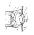
次に、図面を参照するが、これらの図面では、同じ参照番号は主題の開示の同様の構造的特徴または態様を識別する。限定目的ではなく、説明及び例示の目的で、本開示によるノズルの例示的な実施形態の部分図を図1に示し、ノズルは一般的に参照文字100によって表す。本開示によるノズルの他の実施形態または態様は、下記に記載するように図2及び図3に示す。本明細書に記載するシステム及び方法は、ガスタービンエンジン内で複合燃料を燃焼させるために用いられ得、その結果、例えば産業用ガスタービンエンジンは、液体燃料及び/または気体燃料を使用することが可能になり、要求に応じて液体燃料と気体燃料を切り替えるまたは振り分けることが可能になる。2015年3月31に出願された米国特許出願番号14/674,580は、その全体が参照用に本明細書に組み込まれる。 Reference is now made to the drawings, in which the same reference numerals identify similar structural features or aspects of the subject disclosure. For purposes of explanation and illustration, and not limitation, a partial view of an exemplary embodiment of a nozzle according to the present disclosure is shown in FIG. Other embodiments or aspects of the nozzle according to the present disclosure are shown in FIGS. 2 and 3 as described below. The systems and methods described herein can be used to burn composite fuel in a gas turbine engine so that, for example, an industrial gas turbine engine may use liquid and / or gaseous fuel. It becomes possible, and it becomes possible to switch or distribute liquid fuel and gaseous fuel as required. US patent application Ser. No. 14 / 674,580, filed Mar. 31, 2015, is hereby incorporated by reference in its entirety.
ノズル100は、縦軸Aを画定するノズル本体102を含む。ノズル本体102は、放射方向に配設した旋回器106によって空気の供給を受ける内部空気通路104を含み、例えば、2つの空気通路のうちの第1の空気通路は内部空気通路104に空気を供給し、図2の断面図に示すように、円錐状の収束断面を有する。第1の燃料回路108は、縦軸Aに対して、空気通路104から放射方向外側に配設される。第2の燃料回路110は、縦軸Aに対して、第1の燃料回路108から放射方向外側に配設される。第1の燃料回路108及び第2の燃料回路110は、それぞれの燃料回路の入口112及び114からそれぞれの環状燃料回路の出口116及び118に延在する。内部空気通路104内に空気を供給する外部空気通路120、例えば2つの空気通路のうちの第2の空気通路は、燃料回路外部壁122及び外部空気通路壁124の間に画定され、ここで、外部空気通路120は非旋回収束外部空気通路である。複数のスペーサ126には、燃料回路外部壁122及び外部空気通路壁124を接続し、その間に外部空気通路120のためのスペースを設けるが、複数のスペーサ126は旋回のために角度を変更しない、外部空気通路120を通過する空気流は旋回しない。 The
第1及び第2の燃料回路108及び110のそれぞれは、それぞれ複数の螺旋状通路128及び130を含み、各螺旋状通路は、各燃料回路の出口116及び118に対して接線方向に開口している。複数の螺旋状通路130は、少なくとも85°の縦軸Aに対して、流れの出口角度θを画定し得る(図1を参照のこと)。 Each of the first and
第2の燃料回路110は、燃料回路外部壁122と中間燃料回路壁132の間に画定され、第1の燃料回路108は、燃料回路内部壁134と中間燃料回路壁132の間に画定される。中間燃料回路壁132は、縦軸Aに対して、内部燃料回路壁134から放射方向外側に配設され、外部燃料回路壁122は、縦軸Aに対して、中間燃料回路壁132の放射方向外側に配設される。第1の燃料回路108及び第2の燃料回路110のそれぞれの環状燃料回路の出口116及び118は、中間燃料回路壁132のみによって相互から離間されているため、燃料が第1の燃料回路108から流出しても、または第2の燃料回路110から流出しても、あるいはその双方から流出しても、これらの燃料はほぼ同じ環状位置から流出すると考えられる。図2に示すように、燃料回路内部壁134、燃料回路外部壁132、及び燃料回路中間壁122の各々の下流部は、縦軸Aに向かって収束する円錐形状、例えば切頭円錐台状を有する。同様に、外部空気通路壁124は、縦軸Aに向かって収束する円錐形状の下流部を有する。 The
例えば、第2の燃料回路110は、液体燃料を噴射するように構成され得、第1の燃料回路108は、気体燃料を噴射するように構成され得る。従って、マニフォールド136は、別個のタイプの燃料、例えば、液体燃料と気体燃料を別個の燃料回路108及び110に供給するための二重または複合燃料マニフォールドであり得る。第1の燃料回路108の燃料回路の入口112は、燃料マニフォールド136と流体によって連通するように円周方向に離間して配設された1つまたは複数の開口部144を含み得、第2の燃料回路110の燃料回路の入口114は、燃料マニフォールド136と流体によって連通するように、円周方向に離間して配設された1つまたは複数の開口部146を含み得る。放射方向に配設された旋回器106は、環状の内部空気の入口138の周囲に円周方向に相互に離間して配設された放射方向に配設された複数の旋回ベーン107を含む。ノズル本体は、複数のチューブ140及び142を含む。それぞれのチューブ140及び142は、円周方向に離間して配設された開口部144及び146のそれぞれをマニフォールド136に接続する。第1の燃料回路108及び第2の燃料回路110の双方のための複数のチューブ140及び142は、放射方向に配設された複数の旋回ベーン107のそれぞれを軸方向に貫通するため、複数のベーン107は、複数の燃料チューブ140及び142のための熱シールドの役目を果たし得る。1つまたは複数のチューブ140は、第1の燃料回路108からの流れを遮断しながら、任意に第2の燃料回路110の円周方向に離間して配設された複数の開口部146をマニフォールド136に接続することが可能であり、かつ第1の燃料回路108を軸方向に貫通することが可能であるため、2つの燃料回路108及び110からの燃料が混合することはない。1つまたは複数のチューブ142は、第2の燃料回路108の円周方向に離間して配設された開口部144をマニフォールド136に接続することが可能であり、かつ放射方向に配設された旋回器の複数のベーン107のそれぞれを軸方向に貫通することも可能である。図2に破線で示したチューブ142のように、1つまたは複数のチューブ140は、任意に2つの燃料回路108及び110からの燃料を混合することなく複数のチューブ142のそれぞれを貫通することが可能である。 For example, the
次に図3を参照すると、内部空気通路104、外部空気通路120、第1の燃料回路108、及び第2の燃料回路110は、すなわち、ノズル本体102内でプレミクシングを行うことなく拡散火炎噴射を行うように構成され、その結果火炎が、燃焼器のドーム壁148、及びそれぞれの出口116、118、並びに外部空気回路120の出口150の下流に存在する。内部空気通路104は、縦軸Aに沿って放射方向に配設した旋回器106の下流で、パイロット噴射器のような障害に遭遇することはない。図3において、矢印152及び154は、内部空気回路104を通る空気の流れを示し、矢印156及び158は外部空気回路120を通る空気の流れを示し、矢印160及び162は第1の燃料回路108を通る燃料の流れを示し、及び矢印164及び166は第2の燃料回路110を通る燃料の流れを示す。外部空気通路120から流出した外部空気の流れは収束するが、旋回することはない。内部空気通路104からの内部空気の流れは発散し、旋回する。空気と燃料の混合は、ノズル100の下流において、非プレミクス方式によって行われる。ノズル100によって作られる混合ゾーンは、ノズル100の下流で燃料と空気を素早く混合することを可能にする。 Referring now to FIG. 3, the
内部空気通路104及び外部空気通路120の両方の入口が放射方向に向かって開口しているため、両方の入口によって、空気を放射方向へ供給することが可能になる。これによって、例えば逆流型燃焼器内でノズル100内に空気の流れを転動させる場合、圧力低下をより小さくすることが可能になる。混合レベルは、燃料分配器の直径、例えば出口116及び118の直径を調整することによって制御可能であり、その結果、所定の混合レベルに対して要求される空気の流れを確保することができる。 Since both the inlets of the
内部空気通路104の旋回している空気のコアは、ノズル100を通過する空気の流れの40%から50%の量を供給可能であり、この供給量は従来のノズルよりもより大きい。図2に示すように、任意の点火器168はノズル本体102の上流壁170に含まれても良く、起動用に、縦軸Aに沿って同軸方向に配置される。 The swirling air core of the
上記で説明し、並びに図面に示したように、本開示の方法及びシステムによって、優れた特性を有する複合燃料噴射が提供される。これらの特性には、潜在的に大きな直径を備える噴射器を有する拡散火炎噴射、2つの燃料の配分状況に影響されない一貫した火炎、および低いエミッションが含まれる。ここで開示した実施形態は、燃焼器のドーム内で用いる従来型のノズルに取って代わる改良型ノズルとして使用可能である。好適な実施形態を参照して主題の開示の装置及び方法を示し、説明してきたが、当業者は、装置及び方法に対する変更及び/または改良が主題の開示の範囲から逸脱することなく行われ得ることを容易に理解するだろう。 As described above and illustrated in the drawings, the disclosed method and system provide composite fuel injection with superior characteristics. These characteristics include diffusion flame injection with injectors with potentially large diameters, consistent flames unaffected by the distribution of the two fuels, and low emissions. The embodiments disclosed herein can be used as an improved nozzle that replaces the conventional nozzle used in the dome of the combustor. While the subject disclosure apparatus and method have been illustrated and described with reference to preferred embodiments, those skilled in the art can make changes and / or improvements to the apparatus and method without departing from the scope of the subject disclosure. You will understand that easily.
Claims (17)
Translated fromJapanese前記ノズル本体は、
放射方向に配設された旋回器によって供給を受け、円錐状の収束断面を有する内部空気通路と、
前記縦軸に対して前記空気通路から放射方向外側に配設された第1の燃料回路と、
前記縦軸に対して前記第1の燃料回路から放射方向外側に配設された第2の燃料回路であって、前記第1の燃料回路及び前記第2の燃料回路の各々は、それぞれの燃料回路の入口からそれぞれの環状燃料回路の出口まで延在する前記第2の燃料回路と、
燃料回路外部壁と外部空気通路壁の間に画定された外部空気通路であって、前記外部空気通路は非旋回収束外部空気通路である前記外部空気通路と、
を備える前記ノズル。A nozzle comprising a nozzle body defining a longitudinal axis,
The nozzle body is
An internal air passage supplied by a swirler arranged in a radial direction and having a conical converging section;
A first fuel circuit disposed radially outward from the air passage with respect to the longitudinal axis;
A second fuel circuit disposed radially outward from the first fuel circuit with respect to the longitudinal axis, wherein each of the first fuel circuit and the second fuel circuit is a respective fuel Said second fuel circuit extending from the inlet of the circuit to the outlet of the respective annular fuel circuit;
An external air passage defined between a fuel circuit external wall and an external air passage wall, wherein the external air passage is a non-swirl converging external air passage; and
The nozzle comprising:
前記空気流通路及び前記燃料流回路はいずれも、少なくともその一部が複数対の切頭円錐台状の壁の間に画定され、
前記空気流通路及び前記燃料流回路は、前記ノズルを介する軸方向に流れる流体によって決定されるように、前記第1の空気流通路、前記第1の燃料流回路、前記第2の燃料流回路、前記第2の空気流通路の順番で、上流から下流に向かう順番に配設され、
前記第1の空気流通路は、空気の流れを旋回するように構成された複数の第1の旋回ベーンを介して空気の供給を受け、
前記第2の空気流通路は、空気の流れを旋回するように構成されていない複数の第2のベーンを介して空気の供給を受ける、前記ノズル。A nozzle comprising a nozzle body defining a longitudinal axis and including first and second air flow passages and first and second fuel flow circuits,
The air flow passage and the fuel flow circuit are both at least partially defined between a plurality of pairs of frustoconical walls;
The first air flow path, the first fuel flow circuit, and the second fuel flow circuit are determined by the fluid flowing in the axial direction through the nozzle. , Arranged in the order of the second air flow path, from upstream to downstream,
The first air flow passage is supplied with air via a plurality of first swirl vanes configured to swirl the air flow;
The nozzle, wherein the second air flow passage is supplied with air via a plurality of second vanes that are not configured to swirl the air flow.
Applications Claiming Priority (2)
| Application Number | Priority Date | Filing Date | Title |
|---|---|---|---|
| US15/382,044US10634355B2 (en) | 2016-12-16 | 2016-12-16 | Dual fuel radial flow nozzles |
| US15/382,044 | 2016-12-16 |
Publications (2)
| Publication Number | Publication Date |
|---|---|
| JP2018096685Atrue JP2018096685A (en) | 2018-06-21 |
| JP6962804B2 JP6962804B2 (en) | 2021-11-05 |
Family
ID=60811789
Family Applications (1)
| Application Number | Title | Priority Date | Filing Date |
|---|---|---|---|
| JP2017241330AActiveJP6962804B2 (en) | 2016-12-16 | 2017-12-18 | Nozzle to flow compound fuel in the radial direction |
Country Status (3)
| Country | Link |
|---|---|
| US (1) | US10634355B2 (en) |
| EP (1) | EP3336434B1 (en) |
| JP (1) | JP6962804B2 (en) |
Cited By (1)
| Publication number | Priority date | Publication date | Assignee | Title |
|---|---|---|---|---|
| KR20220099724A (en)* | 2021-01-07 | 2022-07-14 | 두산에너빌리티 주식회사 | Nozzle assembly, Combustor and Gas turbine comprising the same |
Families Citing this family (6)
| Publication number | Priority date | Publication date | Assignee | Title |
|---|---|---|---|---|
| US10344981B2 (en)* | 2016-12-16 | 2019-07-09 | Delavan Inc. | Staged dual fuel radial nozzle with radial liquid fuel distributor |
| US20190186742A1 (en)* | 2017-12-15 | 2019-06-20 | Delavan, Inc. | Tapered helical fuel distributor |
| US12070760B2 (en)* | 2019-07-22 | 2024-08-27 | Collins Engine Nozzles, Inc. | Fluid distributor passages |
| EP3904768B1 (en)* | 2020-04-28 | 2024-04-17 | Collins Engine Nozzles, Inc. | Fluid nozzle |
| JP7636227B2 (en)* | 2021-03-26 | 2025-02-26 | 本田技研工業株式会社 | Fuel nozzle device for gas turbine |
| CN115289473B (en)* | 2022-08-12 | 2025-05-30 | 北京天地融创科技股份有限公司 | Gas-powder dual fuel burner |
Citations (8)
| Publication number | Priority date | Publication date | Assignee | Title |
|---|---|---|---|---|
| US6374615B1 (en)* | 2000-01-28 | 2002-04-23 | Alliedsignal, Inc | Low cost, low emissions natural gas combustor |
| JP2003522929A (en)* | 2000-02-14 | 2003-07-29 | ウルスタイン・トゥルビーン・アーエス | Equipment in burners for gas turbines |
| JP2003262337A (en)* | 2002-03-07 | 2003-09-19 | Snecma Moteurs | Multi-mode system for injecting fuel-air mixture into combustion chamber |
| US20100126176A1 (en)* | 2008-11-26 | 2010-05-27 | Ik Soo Kim | Dual swirler |
| JP2010159957A (en)* | 2009-01-07 | 2010-07-22 | General Electric Co <Ge> | Method and apparatus for injecting fuel in turbine engine |
| US20120260663A1 (en)* | 2011-04-12 | 2012-10-18 | Rolls-Royce Plc | Fuel supply arrangement |
| JP2014132214A (en)* | 2013-01-07 | 2014-07-17 | General Electric Co <Ge> | Fuel injector for supplying fuel to combustor |
| US20160290649A1 (en)* | 2015-03-31 | 2016-10-06 | Delavan Inc | Fuel nozzles |
Family Cites Families (8)
| Publication number | Priority date | Publication date | Assignee | Title |
|---|---|---|---|---|
| GB1421399A (en)* | 1972-11-13 | 1976-01-14 | Snecma | Fuel injectors |
| US5505045A (en)* | 1992-11-09 | 1996-04-09 | Fuel Systems Textron, Inc. | Fuel injector assembly with first and second fuel injectors and inner, outer, and intermediate air discharge chambers |
| US6272840B1 (en)* | 2000-01-13 | 2001-08-14 | Cfd Research Corporation | Piloted airblast lean direct fuel injector |
| US7174717B2 (en)* | 2003-12-24 | 2007-02-13 | Pratt & Whitney Canada Corp. | Helical channel fuel distributor and method |
| US9188063B2 (en)* | 2011-11-03 | 2015-11-17 | Delavan Inc. | Injectors for multipoint injection |
| US9222673B2 (en)* | 2012-10-09 | 2015-12-29 | General Electric Company | Fuel nozzle and method of assembling the same |
| US9021781B2 (en)* | 2013-01-04 | 2015-05-05 | General Electric Company | Fuel injector having an ignitor for igniting a combustor of a gas turbine |
| US10385809B2 (en) | 2015-03-31 | 2019-08-20 | Delavan Inc. | Fuel nozzles |
- 2016
- 2016-12-16USUS15/382,044patent/US10634355B2/enactiveActive
- 2017
- 2017-12-15EPEP17207794.3Apatent/EP3336434B1/enactiveActive
- 2017-12-18JPJP2017241330Apatent/JP6962804B2/enactiveActive
Patent Citations (8)
| Publication number | Priority date | Publication date | Assignee | Title |
|---|---|---|---|---|
| US6374615B1 (en)* | 2000-01-28 | 2002-04-23 | Alliedsignal, Inc | Low cost, low emissions natural gas combustor |
| JP2003522929A (en)* | 2000-02-14 | 2003-07-29 | ウルスタイン・トゥルビーン・アーエス | Equipment in burners for gas turbines |
| JP2003262337A (en)* | 2002-03-07 | 2003-09-19 | Snecma Moteurs | Multi-mode system for injecting fuel-air mixture into combustion chamber |
| US20100126176A1 (en)* | 2008-11-26 | 2010-05-27 | Ik Soo Kim | Dual swirler |
| JP2010159957A (en)* | 2009-01-07 | 2010-07-22 | General Electric Co <Ge> | Method and apparatus for injecting fuel in turbine engine |
| US20120260663A1 (en)* | 2011-04-12 | 2012-10-18 | Rolls-Royce Plc | Fuel supply arrangement |
| JP2014132214A (en)* | 2013-01-07 | 2014-07-17 | General Electric Co <Ge> | Fuel injector for supplying fuel to combustor |
| US20160290649A1 (en)* | 2015-03-31 | 2016-10-06 | Delavan Inc | Fuel nozzles |
Cited By (2)
| Publication number | Priority date | Publication date | Assignee | Title |
|---|---|---|---|---|
| KR20220099724A (en)* | 2021-01-07 | 2022-07-14 | 두산에너빌리티 주식회사 | Nozzle assembly, Combustor and Gas turbine comprising the same |
| KR102433706B1 (en) | 2021-01-07 | 2022-08-19 | 두산에너빌리티 주식회사 | Nozzle assembly, Combustor and Gas turbine comprising the same |
Also Published As
| Publication number | Publication date |
|---|---|
| US10634355B2 (en) | 2020-04-28 |
| US20180172274A1 (en) | 2018-06-21 |
| EP3336434B1 (en) | 2019-07-31 |
| EP3336434A1 (en) | 2018-06-20 |
| JP6962804B2 (en) | 2021-11-05 |
Similar Documents
| Publication | Publication Date | Title |
|---|---|---|
| JP6962804B2 (en) | Nozzle to flow compound fuel in the radial direction | |
| JP6940393B2 (en) | nozzle | |
| JP5468812B2 (en) | Combustor assembly and fuel nozzle for gas turbine engine | |
| US20220356845A1 (en) | Fuel nozzle with integrated metering and flashback system | |
| JP6940394B2 (en) | nozzle | |
| US7908863B2 (en) | Fuel nozzle for a gas turbine engine and method for fabricating the same | |
| US9182124B2 (en) | Gas turbine and fuel injector for the same | |
| CN206973617U (en) | Guide's pre-mixing nozzle and fuel nozzle assembly | |
| JPH07305848A (en) | Reducing method of combustion instability in fuel nozzle-assembly, gas turbine device and low nox gas turbine device | |
| JP2011196681A (en) | Combustor with pre-mixing primary fuel-nozzle assembly | |
| US11846425B2 (en) | Dual fuel gas turbine engine pilot nozzles | |
| US11649965B2 (en) | Fuel nozzle for a gas turbine with radial swirler and axial swirler and gas turbine | |
| KR101546216B1 (en) | Premix burner of the multi-cone type for a gas turbine | |
| EP3465009B1 (en) | Fuel nozzle for a gas turbine with radial swirler and axial swirler and gas turbine | |
| JP6134510B2 (en) | Turbomachine combustor | |
| CN106091012A (en) | Nozzle for gas turbine combustor | |
| US11448175B1 (en) | Fuel nozzle | |
| US20130152594A1 (en) | Gas turbine and fuel injector for the same | |
| JPH08261412A (en) | Atomizing combustor |
Legal Events
| Date | Code | Title | Description |
|---|---|---|---|
| A621 | Written request for application examination | Free format text:JAPANESE INTERMEDIATE CODE: A621 Effective date:20200619 | |
| A977 | Report on retrieval | Free format text:JAPANESE INTERMEDIATE CODE: A971007 Effective date:20210317 | |
| A131 | Notification of reasons for refusal | Free format text:JAPANESE INTERMEDIATE CODE: A131 Effective date:20210330 | |
| A601 | Written request for extension of time | Free format text:JAPANESE INTERMEDIATE CODE: A601 Effective date:20210629 | |
| A521 | Request for written amendment filed | Free format text:JAPANESE INTERMEDIATE CODE: A523 Effective date:20210715 | |
| TRDD | Decision of grant or rejection written | ||
| A01 | Written decision to grant a patent or to grant a registration (utility model) | Free format text:JAPANESE INTERMEDIATE CODE: A01 Effective date:20210914 | |
| A61 | First payment of annual fees (during grant procedure) | Free format text:JAPANESE INTERMEDIATE CODE: A61 Effective date:20211014 | |
| R150 | Certificate of patent or registration of utility model | Ref document number:6962804 Country of ref document:JP Free format text:JAPANESE INTERMEDIATE CODE: R150 | |
| R250 | Receipt of annual fees | Free format text:JAPANESE INTERMEDIATE CODE: R250 |