JP2018093121A - Cleaning method - Google Patents
Cleaning methodDownload PDFInfo
- Publication number
- JP2018093121A JP2018093121AJP2016237074AJP2016237074AJP2018093121AJP 2018093121 AJP2018093121 AJP 2018093121AJP 2016237074 AJP2016237074 AJP 2016237074AJP 2016237074 AJP2016237074 AJP 2016237074AJP 2018093121 AJP2018093121 AJP 2018093121A
- Authority
- JP
- Japan
- Prior art keywords
- cleaning
- gas
- cleaning step
- rotary table
- rotated
- Prior art date
- Legal status (The legal status is an assumption and is not a legal conclusion. Google has not performed a legal analysis and makes no representation as to the accuracy of the status listed.)
- Granted
Links
Images


Classifications
- H—ELECTRICITY
- H01—ELECTRIC ELEMENTS
- H01L—SEMICONDUCTOR DEVICES NOT COVERED BY CLASS H10
- H01L21/00—Processes or apparatus adapted for the manufacture or treatment of semiconductor or solid state devices or of parts thereof
- H01L21/02—Manufacture or treatment of semiconductor devices or of parts thereof
- H01L21/02041—Cleaning
- H01L21/02043—Cleaning before device manufacture, i.e. Begin-Of-Line process
- H01L21/02046—Dry cleaning only
- C—CHEMISTRY; METALLURGY
- C23—COATING METALLIC MATERIAL; COATING MATERIAL WITH METALLIC MATERIAL; CHEMICAL SURFACE TREATMENT; DIFFUSION TREATMENT OF METALLIC MATERIAL; COATING BY VACUUM EVAPORATION, BY SPUTTERING, BY ION IMPLANTATION OR BY CHEMICAL VAPOUR DEPOSITION, IN GENERAL; INHIBITING CORROSION OF METALLIC MATERIAL OR INCRUSTATION IN GENERAL
- C23C—COATING METALLIC MATERIAL; COATING MATERIAL WITH METALLIC MATERIAL; SURFACE TREATMENT OF METALLIC MATERIAL BY DIFFUSION INTO THE SURFACE, BY CHEMICAL CONVERSION OR SUBSTITUTION; COATING BY VACUUM EVAPORATION, BY SPUTTERING, BY ION IMPLANTATION OR BY CHEMICAL VAPOUR DEPOSITION, IN GENERAL
- C23C16/00—Chemical coating by decomposition of gaseous compounds, without leaving reaction products of surface material in the coating, i.e. chemical vapour deposition [CVD] processes
- C23C16/44—Chemical coating by decomposition of gaseous compounds, without leaving reaction products of surface material in the coating, i.e. chemical vapour deposition [CVD] processes characterised by the method of coating
- C23C16/4401—Means for minimising impurities, e.g. dust, moisture or residual gas, in the reaction chamber
- C23C16/4405—Cleaning of reactor or parts inside the reactor by using reactive gases
- C—CHEMISTRY; METALLURGY
- C23—COATING METALLIC MATERIAL; COATING MATERIAL WITH METALLIC MATERIAL; CHEMICAL SURFACE TREATMENT; DIFFUSION TREATMENT OF METALLIC MATERIAL; COATING BY VACUUM EVAPORATION, BY SPUTTERING, BY ION IMPLANTATION OR BY CHEMICAL VAPOUR DEPOSITION, IN GENERAL; INHIBITING CORROSION OF METALLIC MATERIAL OR INCRUSTATION IN GENERAL
- C23C—COATING METALLIC MATERIAL; COATING MATERIAL WITH METALLIC MATERIAL; SURFACE TREATMENT OF METALLIC MATERIAL BY DIFFUSION INTO THE SURFACE, BY CHEMICAL CONVERSION OR SUBSTITUTION; COATING BY VACUUM EVAPORATION, BY SPUTTERING, BY ION IMPLANTATION OR BY CHEMICAL VAPOUR DEPOSITION, IN GENERAL
- C23C14/00—Coating by vacuum evaporation, by sputtering or by ion implantation of the coating forming material
- C23C14/22—Coating by vacuum evaporation, by sputtering or by ion implantation of the coating forming material characterised by the process of coating
- C23C14/50—Substrate holders
- C23C14/505—Substrate holders for rotation of the substrates
- C—CHEMISTRY; METALLURGY
- C23—COATING METALLIC MATERIAL; COATING MATERIAL WITH METALLIC MATERIAL; CHEMICAL SURFACE TREATMENT; DIFFUSION TREATMENT OF METALLIC MATERIAL; COATING BY VACUUM EVAPORATION, BY SPUTTERING, BY ION IMPLANTATION OR BY CHEMICAL VAPOUR DEPOSITION, IN GENERAL; INHIBITING CORROSION OF METALLIC MATERIAL OR INCRUSTATION IN GENERAL
- C23C—COATING METALLIC MATERIAL; COATING MATERIAL WITH METALLIC MATERIAL; SURFACE TREATMENT OF METALLIC MATERIAL BY DIFFUSION INTO THE SURFACE, BY CHEMICAL CONVERSION OR SUBSTITUTION; COATING BY VACUUM EVAPORATION, BY SPUTTERING, BY ION IMPLANTATION OR BY CHEMICAL VAPOUR DEPOSITION, IN GENERAL
- C23C16/00—Chemical coating by decomposition of gaseous compounds, without leaving reaction products of surface material in the coating, i.e. chemical vapour deposition [CVD] processes
- C23C16/22—Chemical coating by decomposition of gaseous compounds, without leaving reaction products of surface material in the coating, i.e. chemical vapour deposition [CVD] processes characterised by the deposition of inorganic material, other than metallic material
- C23C16/30—Deposition of compounds, mixtures or solid solutions, e.g. borides, carbides, nitrides
- C23C16/40—Oxides
- C23C16/401—Oxides containing silicon
- C—CHEMISTRY; METALLURGY
- C23—COATING METALLIC MATERIAL; COATING MATERIAL WITH METALLIC MATERIAL; CHEMICAL SURFACE TREATMENT; DIFFUSION TREATMENT OF METALLIC MATERIAL; COATING BY VACUUM EVAPORATION, BY SPUTTERING, BY ION IMPLANTATION OR BY CHEMICAL VAPOUR DEPOSITION, IN GENERAL; INHIBITING CORROSION OF METALLIC MATERIAL OR INCRUSTATION IN GENERAL
- C23C—COATING METALLIC MATERIAL; COATING MATERIAL WITH METALLIC MATERIAL; SURFACE TREATMENT OF METALLIC MATERIAL BY DIFFUSION INTO THE SURFACE, BY CHEMICAL CONVERSION OR SUBSTITUTION; COATING BY VACUUM EVAPORATION, BY SPUTTERING, BY ION IMPLANTATION OR BY CHEMICAL VAPOUR DEPOSITION, IN GENERAL
- C23C16/00—Chemical coating by decomposition of gaseous compounds, without leaving reaction products of surface material in the coating, i.e. chemical vapour deposition [CVD] processes
- C23C16/44—Chemical coating by decomposition of gaseous compounds, without leaving reaction products of surface material in the coating, i.e. chemical vapour deposition [CVD] processes characterised by the method of coating
- C23C16/455—Chemical coating by decomposition of gaseous compounds, without leaving reaction products of surface material in the coating, i.e. chemical vapour deposition [CVD] processes characterised by the method of coating characterised by the method used for introducing gases into reaction chamber or for modifying gas flows in reaction chamber
- C23C16/45523—Pulsed gas flow or change of composition over time
- C23C16/45525—Atomic layer deposition [ALD]
- C23C16/45544—Atomic layer deposition [ALD] characterized by the apparatus
- C23C16/45548—Atomic layer deposition [ALD] characterized by the apparatus having arrangements for gas injection at different locations of the reactor for each ALD half-reaction
- C—CHEMISTRY; METALLURGY
- C23—COATING METALLIC MATERIAL; COATING MATERIAL WITH METALLIC MATERIAL; CHEMICAL SURFACE TREATMENT; DIFFUSION TREATMENT OF METALLIC MATERIAL; COATING BY VACUUM EVAPORATION, BY SPUTTERING, BY ION IMPLANTATION OR BY CHEMICAL VAPOUR DEPOSITION, IN GENERAL; INHIBITING CORROSION OF METALLIC MATERIAL OR INCRUSTATION IN GENERAL
- C23C—COATING METALLIC MATERIAL; COATING MATERIAL WITH METALLIC MATERIAL; SURFACE TREATMENT OF METALLIC MATERIAL BY DIFFUSION INTO THE SURFACE, BY CHEMICAL CONVERSION OR SUBSTITUTION; COATING BY VACUUM EVAPORATION, BY SPUTTERING, BY ION IMPLANTATION OR BY CHEMICAL VAPOUR DEPOSITION, IN GENERAL
- C23C16/00—Chemical coating by decomposition of gaseous compounds, without leaving reaction products of surface material in the coating, i.e. chemical vapour deposition [CVD] processes
- C23C16/44—Chemical coating by decomposition of gaseous compounds, without leaving reaction products of surface material in the coating, i.e. chemical vapour deposition [CVD] processes characterised by the method of coating
- C23C16/458—Chemical coating by decomposition of gaseous compounds, without leaving reaction products of surface material in the coating, i.e. chemical vapour deposition [CVD] processes characterised by the method of coating characterised by the method used for supporting substrates in the reaction chamber
- C23C16/4582—Rigid and flat substrates, e.g. plates or discs
- C23C16/4583—Rigid and flat substrates, e.g. plates or discs the substrate being supported substantially horizontally
- C23C16/4584—Rigid and flat substrates, e.g. plates or discs the substrate being supported substantially horizontally the substrate being rotated
- C—CHEMISTRY; METALLURGY
- C23—COATING METALLIC MATERIAL; COATING MATERIAL WITH METALLIC MATERIAL; CHEMICAL SURFACE TREATMENT; DIFFUSION TREATMENT OF METALLIC MATERIAL; COATING BY VACUUM EVAPORATION, BY SPUTTERING, BY ION IMPLANTATION OR BY CHEMICAL VAPOUR DEPOSITION, IN GENERAL; INHIBITING CORROSION OF METALLIC MATERIAL OR INCRUSTATION IN GENERAL
- C23C—COATING METALLIC MATERIAL; COATING MATERIAL WITH METALLIC MATERIAL; SURFACE TREATMENT OF METALLIC MATERIAL BY DIFFUSION INTO THE SURFACE, BY CHEMICAL CONVERSION OR SUBSTITUTION; COATING BY VACUUM EVAPORATION, BY SPUTTERING, BY ION IMPLANTATION OR BY CHEMICAL VAPOUR DEPOSITION, IN GENERAL
- C23C22/00—Chemical surface treatment of metallic material by reaction of the surface with a reactive liquid, leaving reaction products of surface material in the coating, e.g. conversion coatings, passivation of metals
- C23C22/05—Chemical surface treatment of metallic material by reaction of the surface with a reactive liquid, leaving reaction products of surface material in the coating, e.g. conversion coatings, passivation of metals using aqueous solutions
- C23C22/06—Chemical surface treatment of metallic material by reaction of the surface with a reactive liquid, leaving reaction products of surface material in the coating, e.g. conversion coatings, passivation of metals using aqueous solutions using aqueous acidic solutions with pH less than 6
- C23C22/34—Chemical surface treatment of metallic material by reaction of the surface with a reactive liquid, leaving reaction products of surface material in the coating, e.g. conversion coatings, passivation of metals using aqueous solutions using aqueous acidic solutions with pH less than 6 containing fluorides or complex fluorides
- H—ELECTRICITY
- H01—ELECTRIC ELEMENTS
- H01L—SEMICONDUCTOR DEVICES NOT COVERED BY CLASS H10
- H01L21/00—Processes or apparatus adapted for the manufacture or treatment of semiconductor or solid state devices or of parts thereof
- H01L21/67—Apparatus specially adapted for handling semiconductor or electric solid state devices during manufacture or treatment thereof; Apparatus specially adapted for handling wafers during manufacture or treatment of semiconductor or electric solid state devices or components ; Apparatus not specifically provided for elsewhere
- H01L21/67005—Apparatus not specifically provided for elsewhere
- H01L21/67011—Apparatus for manufacture or treatment
- H01L21/67017—Apparatus for fluid treatment
- H01L21/67028—Apparatus for fluid treatment for cleaning followed by drying, rinsing, stripping, blasting or the like
Landscapes
- Chemical & Material Sciences (AREA)
- Engineering & Computer Science (AREA)
- Chemical Kinetics & Catalysis (AREA)
- Materials Engineering (AREA)
- Mechanical Engineering (AREA)
- Metallurgy (AREA)
- Organic Chemistry (AREA)
- General Chemical & Material Sciences (AREA)
- Manufacturing & Machinery (AREA)
- Physics & Mathematics (AREA)
- Condensed Matter Physics & Semiconductors (AREA)
- General Physics & Mathematics (AREA)
- Computer Hardware Design (AREA)
- Microelectronics & Electronic Packaging (AREA)
- Power Engineering (AREA)
- Inorganic Chemistry (AREA)
- Chemical Vapour Deposition (AREA)
- Drying Of Semiconductors (AREA)
Abstract
Translated fromJapaneseDescription
Translated fromJapanese本発明は、クリーニング方法に関する。 The present invention relates to a cleaning method.
半導体装置等の製造に用いられる成膜装置においては、基板の上面だけではなく、基板が載置される回転テーブルの上面、側面、下面等にも膜が堆積する。そして、回転テーブルの上面、側面、下面等に堆積した膜の膜厚が厚くなると、堆積した膜が剥がれ、パーティクルを生じる。そのため、処理室内にクリーニングガスを定期的に供給し、回転テーブルの上面、側面、下面等に堆積した膜を除去している(例えば、特許文献1参照)。 In a film forming apparatus used for manufacturing a semiconductor device or the like, a film is deposited not only on an upper surface of a substrate but also on an upper surface, a side surface, a lower surface, and the like of a rotary table on which the substrate is placed. And when the film thickness of the film | membrane deposited on the upper surface of the turntable, the side surface, the lower surface, etc. becomes thick, the deposited film | membrane peels and a particle is produced. Therefore, a cleaning gas is periodically supplied into the processing chamber to remove films deposited on the upper surface, side surfaces, lower surface, and the like of the rotary table (see, for example, Patent Document 1).
しかしながら、上記の方法では、クリーニングガスを供給するノズルと、回転テーブルとの間隔が狭いため、ノズルから供給されるクリーニングガスの流速が速く、クリーニングガスの多くが回転テーブルの上面に堆積した膜を除去する前に排気される。そのため、回転テーブルの上面に堆積した膜を除去するのに要するクリーニング時間が長くなり、また、回転テーブルの面内において堆積した膜が除去される時間に差が生じていた。 However, in the above method, since the gap between the nozzle for supplying the cleaning gas and the rotary table is narrow, the flow rate of the cleaning gas supplied from the nozzle is fast, and a film in which most of the cleaning gas is deposited on the upper surface of the rotary table is formed. Exhaust before removal. For this reason, the cleaning time required to remove the film deposited on the upper surface of the turntable becomes longer, and there is a difference in the time taken to remove the deposited film in the surface of the turntable.
そこで、本発明の一態様では、クリーニング時間を短縮し、均一性の高いクリーニングを行うことが可能なクリーニング方法を提供することを目的とする。 In view of the above, an object of one embodiment of the present invention is to provide a cleaning method capable of reducing cleaning time and performing highly uniform cleaning.
上記目的を達成するため、本発明の一態様に係るクリーニング方法は、処理室内において基板を上面に載置可能な回転テーブルを、第1のクリーニング位置において回転させた状態で、前記回転テーブルの基板載置面の上方からクリーニングガスを供給する第1のクリーニング工程と、前記回転テーブルを、前記第1のクリーニング位置よりも下方である第2のクリーニング位置において回転させた状態で、前記回転テーブルの基板載置面の上方から前記クリーニングガスを供給する第2のクリーニング工程と、を含む。 In order to achieve the above object, a cleaning method according to one embodiment of the present invention includes a rotating table on which a substrate can be placed on an upper surface in a processing chamber in a state where the rotating table is rotated at a first cleaning position. A first cleaning step of supplying a cleaning gas from above the mounting surface; and a state in which the rotary table is rotated at a second cleaning position that is lower than the first cleaning position. A second cleaning step of supplying the cleaning gas from above the substrate placement surface.
開示のクリーニング方法によれば、クリーニング時間を短縮し、均一性の高いクリーニングを行うことができる。 According to the disclosed cleaning method, cleaning time can be shortened and highly uniform cleaning can be performed.
以下、本発明を実施するための形態について図面を参照して説明する。なお、本明細書及び図面において、実質的に同一の構成については、同一の符号を付することにより重複した説明を省く。 Hereinafter, embodiments for carrying out the present invention will be described with reference to the drawings. In addition, in this specification and drawing, about the substantially same structure, the duplicate description is abbreviate | omitted by attaching | subjecting the same code | symbol.
(成膜装置)
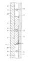
まず、本発明の実施形態に係るクリーニング方法が適用可能な成膜装置の一例について説明する。図1は、本発明の実施形態に係る成膜装置の概略断面図である。図2は、図1の成膜装置の真空容器内の構成を示す概略斜視図である。図3は、図1の成膜装置の真空容器内の構成を示す概略平面図である。なお、図2及び図3では、説明の便宜上、天板の図示を省略している。(Deposition system)
First, an example of a film forming apparatus to which the cleaning method according to the embodiment of the present invention can be applied will be described. FIG. 1 is a schematic cross-sectional view of a film forming apparatus according to an embodiment of the present invention. FIG. 2 is a schematic perspective view showing the configuration inside the vacuum container of the film forming apparatus of FIG. FIG. 3 is a schematic plan view showing the configuration inside the vacuum container of the film forming apparatus of FIG. 2 and 3, the top plate is not shown for convenience of explanation.
図1から図3までを参照すると、成膜装置は、ほぼ円形の平面形状を有する扁平な真空容器1と、真空容器1内に設けられ、真空容器1の中心に回転中心を有する回転テーブル2と、を備えている。真空容器1は、内部に収容した基板である半導体ウエハ(以下「ウエハW」という。)の上面に成膜処理を行うための処理室である。真空容器1は、有底の円筒形状を有する容器本体12と、容器本体12の上面に対して、例えばOリング等のシール部材13を介して気密に着脱可能に配置される天板11とを有している。 Referring to FIGS. 1 to 3, a film forming apparatus includes a
回転テーブル2は、真空容器1内に回転可能に設けられている。回転テーブル2は、例えば石英により形成されている。回転テーブル2は、中心部にて円筒形状のコア部21に固定されている。コア部21は、鉛直方向に伸びる回転軸22の上端に固定されている。回転軸22は、真空容器1の底部14を貫通し、下端が駆動部23に取り付けられている。駆動部23は、例えば圧空シリンダとステッピングモータとを含み、回転軸22を昇降させることで回転テーブル2を昇降させ、回転軸22を鉛直軸回りに回転させることで回転テーブル2を回転させる。回転軸22及び駆動部23は、上面が開口した筒状のケース体20内に収納されている。ケース体20は、その上面に設けられたフランジ部が、鉛直方向に伸縮可能なベローズ16を介して真空容器1の底部14の下面に気密に取り付けられており、ケース体20の内部雰囲気と外部雰囲気との気密状態が維持されている。回転テーブル2が昇降する場合には、回転テーブル2の昇降に対応してベローズ16が伸縮するため、ケース体20の内部雰囲気と外部雰囲気との気密状態を維持することができる。 The
回転テーブル2の上面には、図2及び図3に示されるように、回転テーブル2の回転方向(周方向)に沿って複数(図示の例では6枚)のウエハWを載置可能な円形状の凹部2aが設けられている。なお、図3には便宜上、1個の凹部2aだけにウエハWを示している。凹部2aは、ウエハWの直径よりも僅かに例えば4mm大きい内径と、ウエハWの厚さにほぼ等しい深さとを有している。したがって、ウエハWが凹部2aに収容されると、ウエハWの表面と回転テーブル2の表面(ウエハWが載置されない領域)とが同じ高さになる。凹部2aの底面には、ウエハWの裏面を支えてウエハWを昇降させるための例えば3本の昇降ピンが貫通する貫通孔(いずれも図示せず)が形成されている。 As shown in FIGS. 2 and 3, on the upper surface of the
回転テーブル2の上方には、図2及び図3に示されるように、例えば石英により形成された反応ガスノズル31、32、クリーニングガスノズル33及び分離ガスノズル41、42が真空容器1の周方向に互いに間隔をおいて配置されている。図示の例では、後述の搬送口15から時計回り(回転テーブル2の回転方向)に、分離ガスノズル41、クリーニングガスノズル33、反応ガスノズル31、分離ガスノズル42及び反応ガスノズル32がこの順番で配列されている。これらのノズル31、32、33、41、42は、各ノズル31、32、33、41、42の基端部であるガス導入ポート31a、32a、33a、41a、42a(図3)を容器本体12の外周面に固定することにより、真空容器1の外周面から真空容器1内に導入され、容器本体12の径方向に沿って回転テーブル2に対して水平に伸びるように取り付けられている。 2 and 3, the
本発明の実施形態においては、図3に示されるように、反応ガスノズル31は、配管110、流量制御器120等を介して、第1の反応ガスの供給源130に接続されている。反応ガスノズル32は、配管111、流量制御器121等を介して、第2の反応ガスの供給源131に接続されている。クリーニングガスノズル33は、配管112、流量制御器122等を介して、クリーニングガスの供給源132に接続されている。分離ガスノズル41、42は、いずれも不図示の配管、流量制御バルブ等を介して、分離ガスの供給源(図示せず)に接続されている。分離ガスとしては、ヘリウム(He)ガスやアルゴン(Ar)ガス等の希ガスや窒素(N2)ガス等の不活性ガスを用いることができる。本発明の実施形態では、N2ガスを用いる例を挙げて説明する。In the embodiment of the present invention, as shown in FIG. 3, the
反応ガスノズル31、32には、回転テーブル2に向かって開口する複数のガス吐出孔35(図4)が、反応ガスノズル31、32の長さ方向に沿って、例えば10mmの間隔で配列されている。反応ガスノズル31の下方領域は、第1の反応ガスをウエハWに吸着させるための第1の処理領域P1となる。反応ガスノズル32の下方領域は、第1の処理領域P1においてウエハWに吸着した第1の反応ガスと反応する第2の反応ガスを供給し、反応生成物の分子層を生成する第2の処理領域P2となる。なお、反応生成物の分子層が、堆積(成膜)される膜を構成する。 In the
第1の反応ガスは、種々のガスであってよいが、一般的には、成膜される膜の原料となる原料ガスが選択され、例えばシリコン酸化膜を成膜する場合には、ビスターシャルブチルアミノシラン(BTBAS)ガス等のシリコン含有ガスが選択される。 The first reaction gas may be various gases, but in general, a raw material gas that is a raw material of a film to be formed is selected. For example, when forming a silicon oxide film, a binary gas is used. A silicon-containing gas such as butylaminosilane (BTBAS) gas is selected.
第2の反応ガスには、第1の反応ガスと反応して反応生成物を生成し得る反応ガスであれば、種々の反応ガスを用いることができ、例えばシリコン酸化膜を成膜する場合にはオゾン(O3)ガス等の酸化ガスが選択される。As the second reaction gas, various reaction gases can be used as long as they can react with the first reaction gas to generate a reaction product. For example, when forming a silicon oxide film Is selected from an oxidizing gas such as ozone (O3 ) gas.
クリーニングガスノズル33は、クリーニングを行う際に使用されるガスノズルである。クリーニングガスノズル33には、反応ガスノズル31、32と同様、回転テーブル2に向かって開口する複数のガス吐出孔(図示せず)が、クリーニングガスノズル33の長さ方向に沿って、例えば10mmの間隔で配列されている。図示の例では、クリーニングガスノズル33は、第1の処理領域P1にクリーニングガスを供給する。なお、クリーニングガスノズル33は、第2の処理領域P2にクリーニングガスを供給可能な位置に設けられていてもよい。また、第1の処理領域P1にクリーニングガスを供給可能な位置及び第2の処理領域P2にクリーニングガスを供給可能な位置に設けられていてもよい。クリーニングガスは、種々のガスであってよいが、例えばシリコン酸化膜を除去する場合には、フッ化塩素(ClF3)、三フッ化窒素(NF3)等のフッ素系のガスが選択される。また、これらのガスを組み合わせてもよい。The cleaning
図2及び図3を参照すると、真空容器1内には2つの凸状部4が設けられている。凸状部4は、分離ガスノズル41、42と共に分離領域Dを構成するため、回転テーブル2に向かって突出するように天板11の下面に取り付けられている。また、凸状部4は、頂部が円弧状に切断された扇型の平面形状を有し、本発明の実施形態においては、内円弧が突出部5(後述)に連結し、外円弧が、真空容器1の容器本体12の内周面に沿うように配置されている。 Referring to FIGS. 2 and 3, two
図4は、図1の成膜装置の回転テーブルの同心円に沿った真空容器の概略断面図であり、反応ガスノズル31から反応ガスノズル32まで回転テーブル2の同心円に沿った真空容器1の断面を示している。なお、図4では、説明の便宜上、ウエハWの図示を省略している。 FIG. 4 is a schematic cross-sectional view of the vacuum vessel along the concentric circle of the turntable of the film forming apparatus of FIG. 1, and shows a cross section of the
図4に示されるように、天板11の下面に凸状部4が取り付けられている。このため、真空容器1内には、凸状部4の下面である平坦な低い天井面44(第1の天井面)と、この天井面44の周方向の両側に位置する、天井面44よりも高い天井面45(第2の天井面)とが存在する。天井面44は、頂部が円弧状に切断された扇型の平面形状を有している。また、図4に示されるように、凸状部4には周方向の中央において、径方向に伸びるように形成された溝部43が形成され、分離ガスノズル42が溝部43内に収容されている。もう一つの凸状部4にも同様に溝部43が形成され、分離ガスノズル41が溝部43内に収容されている。また、高い天井面45の下方の空間に反応ガスノズル31、32がそれぞれ設けられている。これらの反応ガスノズル31、32は、天井面45から離間してウエハWの近傍に設けられている。なお、図4に示されるように、高い天井面45の下方の右側の空間481に反応ガスノズル31が設けられ、高い天井面45の下方の左側の空間482に反応ガスノズル32が設けられる。 As shown in FIG. 4, the
また、凸状部4の溝部43に収容される分離ガスノズル41、42には、回転テーブル2に向かって開口する複数のガス吐出孔42h(図4)が、分離ガスノズル41、42の長さ方向に沿って、例えば10mmの間隔で配列されている。 The
天井面44は、狭隘な空間である分離空間Hを回転テーブル2に対して形成している。分離ガスノズル42のガス吐出孔42hからN2ガスが供給されると、N2ガスは、分離空間Hを通して空間481及び空間482へ向かって流れる。このとき、分離空間Hの容積は空間481及び482の容積よりも小さいため、N2ガスにより分離空間Hの圧力を空間481及び482の圧力に比べて高くすることができる。即ち、空間481及び482の間に圧力の高い分離空間Hが形成される。また、分離空間Hから空間481及び482へ流れ出るN2ガスが、第1の処理領域P1からの第1の反応ガスと、第2の処理領域P2からの第2の反応ガスとに対するカウンターフローとして働く。したがって、第1の処理領域P1からの第1の反応ガスと、第2の処理領域P2からの第2の反応ガスとが分離空間Hにより分離される。よって、真空容器1内において第1の反応ガスと第2の反応ガスとが混合し、反応することが抑制される。The
なお、回転テーブル2の上面に対する天井面44の高さh1は、成膜時の真空容器1内の圧力、回転テーブル2の回転速度、分離ガスの供給量等を考慮し、分離空間Hの圧力を空間481、482の圧力に比べて高くするのに適した高さに設定することが好ましい。 The height h1 of the
一方、天板11の下面には、回転テーブル2を固定するコア部21の外周を囲む突出部5(図2及び図3)が設けられている。突出部5は、本発明の実施形態においては、凸状部4における回転中心側の部位と連続しており、その下面が天井面44と同じ高さに形成されている。 On the other hand, a protrusion 5 (FIGS. 2 and 3) surrounding the outer periphery of the
先に参照した図1は、図3のI−I'線に沿った断面図であり、天井面45が設けられている領域を示している。一方、図5は、天井面44が設けられている領域を示す断面図である。図5に示されるように、扇型の凸状部4の周縁部(真空容器1の外縁側の部位)には、回転テーブル2の外端面に対向するようにL字型に屈曲する屈曲部46が形成されている。屈曲部46は、凸状部4と同様に、分離領域Dの両側から反応ガスが侵入することを抑制して、第1の反応ガスと第2の反応ガスとの混合を抑制する。扇型の凸状部4は天板11に設けられ、天板11が容器本体12から取り外せるようになっていることから、屈曲部46の外周面と容器本体12との間には僅かに隙間がある。屈曲部46の内周面と回転テーブル2の外端面との隙間、及び屈曲部46の外周面と容器本体12との隙間は、例えば回転テーブル2の上面に対する天井面44の高さと同様の寸法に設定されている。 FIG. 1 referred to above is a cross-sectional view taken along the line II ′ of FIG. 3 and shows a region where the
容器本体12の内周面は、分離領域Dでは図5に示されるように屈曲部46の外周面と接近して垂直面に形成されているが、分離領域D以外の領域では図1に示されるように例えば回転テーブル2の外端面と対向する部位から底部14に亘って外方側に窪んでいる。以下、説明の便宜上、概ね矩形の断面形状を有する窪んだ部分を排気領域と記す。具体的には、第1の処理領域P1に連通する排気領域を第1の排気領域E1と記し、第2の処理領域P2に連通する領域を第2の排気領域E2と記す。第1の排気領域E1及び第2の排気領域E2の底部には、図1から図3に示されるように、それぞれ第1の排気口61及び第2の排気口62が形成されている。第1の排気口61及び第2の排気口62は、図1に示されるように、それぞれ排気管63を介して真空排気手段である例えば真空ポンプ64に接続されている。また、真空ポンプ64と排気管63との間に、圧力制御器65が設けられる。 As shown in FIG. 5, the inner peripheral surface of the container
回転テーブル2と真空容器1の底部14との間の空間には、図1及び図5に示されるように加熱手段であるヒータユニット7が設けられ、回転テーブル2を介して回転テーブル2上のウエハWが、プロセスレシピで決められた温度に加熱される。回転テーブル2の周縁付近の下方側には、リング状のカバー部材71が設けられている(図5)。これにより、回転テーブル2の上方空間から第1の排気領域E1、第2の排気領域E2に至るまでの雰囲気とヒータユニット7が置かれている雰囲気とを区画して回転テーブル2の下方領域へのガスの侵入を抑えることができる。カバー部材71は、回転テーブル2の外縁部及び外縁部よりも外周側を下方側から臨むように設けられた内側部材71aと、内側部材71aと真空容器1の内周面との間に設けられた外側部材71bと、を備えている。外側部材71bは、分離領域Dにおいて凸状部4の外縁部に形成された屈曲部46の下方にて、屈曲部46と近接して設けられている。内側部材71aは、回転テーブル2の外縁部下方(及び外縁部よりも僅かに外側の部分の下方)において、ヒータユニット7を全周に亘って取り囲んでいる。 As shown in FIGS. 1 and 5, a
ヒータユニット7が配置されている空間よりも回転中心側の部位における底部14は、回転テーブル2の下面の中心部付近におけるコア部21に接近するように上方側に突出して突出部12aをなしている。突出部12aとコア部21との間は狭い空間になっており、また底部14を貫通する回転軸22の貫通穴の内周面と回転軸22との隙間が狭くなっていて、これら狭い空間はケース体20に連通している。そしてケース体20にはパージガスであるN2ガスを狭い空間内に供給してパージするためのパージガス供給管72が設けられている。また真空容器1の底部14には、ヒータユニット7の下方において周方向に所定の角度間隔で、ヒータユニット7の配置空間をパージするための複数のパージガス供給管73が設けられている(図5には一つのパージガス供給管73を示す)。また、ヒータユニット7と回転テーブル2との間には、ヒータユニット7が設けられた領域へのガスの侵入を抑えるために、外側部材71bの内周面(内側部材71aの上面)から突出部12aの上端部との間を周方向に亘って覆う蓋部材7aが設けられている。蓋部材7aは、例えば石英により形成されている。The
また、真空容器1の天板11の中心部には分離ガス供給管51が接続されていて、天板11とコア部21との間の空間52に分離ガスであるN2ガスを供給するように構成されている。空間52に供給された分離ガスは、突出部5と回転テーブル2との狭い空間50を介して回転テーブル2のウエハ載置領域側の上面に沿って周縁に向けて吐出される。空間50は分離ガスにより空間481及び空間482よりも高い圧力に維持され得る。したがって、空間50により、第1の処理領域P1に供給されるBTBASガスと第2の処理領域P2に供給されるO3ガスとが、中心領域Cを通って混合することが抑制される。即ち、空間50(又は中心領域C)は分離空間H(又は分離領域D)と同様に機能することができる。Further, a separation
さらに、真空容器1の側壁には、図2及び図3に示されるように、外部の搬送アーム10(図3)と回転テーブル2との間でウエハWの受け渡しを行うための搬送口15が形成されている。搬送口15は、図示しないゲートバルブにより開閉される。また、回転テーブル2におけるウエハ載置領域である凹部2aは搬送口15に対向する位置にて搬送アーム10との間でウエハWの受け渡しが行われる。このため、回転テーブル2の下方側において受け渡し位置に対応する部位に、凹部2aを貫通してウエハWを裏面から持ち上げるための受け渡し用の昇降ピン及びその昇降機構(いずれも図示せず)が設けられている。 Further, as shown in FIG. 2 and FIG. 3, a
また、本発明の実施形態に係る成膜装置には、図1に示されるように、装置全体の動作のコントロールを行うためのコンピュータからなる制御部100が設けられている。制御部100のメモリ内には、制御部100の制御の下に、後述するクリーニング方法を成膜装置に実施させるプログラムが格納されている。プログラムは、後述のクリーニング方法を実行するようにステップ群が組まれている。プログラムは、ハードディスク、コンパクトディスク、光磁気ディスク、メモリカード、フレキシブルディスク等の媒体102に記憶され、所定の読み取り装置により記憶部101へ読み込まれ、制御部100内にインストールされる。 Further, as shown in FIG. 1, the film forming apparatus according to the embodiment of the present invention is provided with a
(成膜方法)
次に、本発明の実施形態に係る成膜装置による成膜方法(成膜工程)について説明する。以下では、シリコン酸化膜を成膜する場合を例に挙げて説明する。(Film formation method)
Next, a film forming method (film forming process) by the film forming apparatus according to the embodiment of the present invention will be described. Hereinafter, a case where a silicon oxide film is formed will be described as an example.
まず、凹部2aが搬送口15(図2及び図3)に対向する位置となるように回転テーブル2を回転させた後、ゲートバルブ(図示せず)を開く。続いて、搬送アーム10により搬送口15を介してウエハWを真空容器1内へ搬入する。ウエハWは、昇降ピン(図示せず)により受け取られ、搬送アーム10が真空容器1から引き抜かれた後に、昇降機構(図示せず)により駆動される昇降ピンによって凹部2aへと下げられる。上記一連の動作を6回繰り返し、6枚のウエハWを対応する凹部2aに載置する。 First, the rotary table 2 is rotated so that the
続いて、分離ガスノズル41、42からN2ガスを供給し、分離ガス供給管51及びパージガス供給管72、73からもN2ガスを供給すると共に、真空ポンプ64及び圧力制御器65(図1)により、真空容器1内を予め設定した圧力に維持する。また、回転テーブル2を所定の速度で、例えば時計回り(図3の矢印Aの方向)に回転させる。回転テーブル2は、ヒータユニット7より予め所定の温度に加熱されており、これにより、回転テーブル2に載置されるウエハWが加熱される。ウエハWが加熱され、所定の温度に維持された後、反応ガスノズル31から第1の処理領域P1にBTBASガスを供給し、反応ガスノズル32から第2の処理領域P2にO3ガスを供給する。Then, theN 2 gas is supplied from the
ウエハWが反応ガスノズル31の下方の第1の処理領域P1を通過するときに、ウエハWの表面にBTBAS分子が吸着する。また、ウエハWが反応ガスノズル32の下方の第2の処理領域P2を通過するときに、ウエハWの表面にO3分子が吸着することにより、O3によりBTBAS分子が酸化される。したがって、回転テーブル2の回転により、ウエハWが第1の処理領域P1及び第2の処理領域P2の両方を一回通過すると、ウエハWの表面に酸化シリコンの一分子層(又は2以上の分子層)が形成される。次いで、ウエハWが第1の処理領域P1及び第2の処理領域P2を交互に複数回通過し、所定の膜厚を有するシリコン酸化膜がウエハWの表面に堆積される。所定の膜厚を有するシリコン酸化膜が堆積された後、BTBASガス及びO3ガスの供給を停止し、回転テーブル2の回転を停止する。そして、搬入動作と逆の動作により搬送アーム10によりウエハWを真空容器1から搬出し、成膜プロセスが終了する。When the wafer W passes through the first processing region P1 below the
このように、成膜工程では、ウエハWの表面にBTBASガスとO3ガスとの反応生成物であるシリコン酸化膜を成膜することが可能である。As described above, in the film forming process, a silicon oxide film that is a reaction product of the BTBAS gas and the O3 gas can be formed on the surface of the wafer W.
ところで、成膜工程では、ウエハWの表面だけでなく、回転テーブル2の上面、側面、下面等にもガスが曝されるため、ウエハWの表面のみならず、回転テーブル2の上面、側面、下面等にもシリコン酸化膜等の反応生成物が成膜されてしまう。そして、回転テーブル2の上面、側面、下面等に成膜されるシリコン酸化膜等の反応生成物の膜厚が厚くなると、反応生成物が剥がれ、パーティクルとなる。このように真空容器1内においてパーティクルが発生すると、ウエハWの表面に成膜されるシリコン酸化膜の膜中にパーティクルが取り込まれ、膜質が低下する。 By the way, in the film forming process, not only the surface of the wafer W but also the upper surface, side surface, and lower surface of the
そこで、回転テーブル2の上面に所定の膜厚の反応生成物が成膜された場合、ウエハWに成膜されるシリコン酸化膜の膜中に含まれるパーティクルが所定量を超えた場合、所定の連続運転時間を経過した場合等に、クリーニングを行うのが一般的である。 Therefore, when a reaction product having a predetermined film thickness is formed on the upper surface of the
しかしながら、クリーニングガスを供給するノズルと、回転テーブルとの間隔が狭い場合、ノズルから供給されるクリーニングガスの流速が速く、クリーニングガスの多くが回転テーブルの上面に堆積した膜を除去する前に排気される。そのため、回転テーブルの上面に堆積した膜を除去するのに要するクリーニング時間が長くなり、また、回転テーブルの面内において堆積した膜が除去される時間に差が生じていた。 However, when the distance between the nozzle for supplying the cleaning gas and the rotary table is narrow, the flow rate of the cleaning gas supplied from the nozzle is fast, and most of the cleaning gas is exhausted before removing the film deposited on the upper surface of the rotary table. Is done. For this reason, the cleaning time required to remove the film deposited on the upper surface of the turntable becomes longer, and there is a difference in the time taken to remove the deposited film in the surface of the turntable.
以下では、クリーニング時間を短縮し、均一性の高いクリーニングを行うことができる本発明の実施形態に係るクリーニング方法について説明する。 In the following, a cleaning method according to an embodiment of the present invention that can shorten the cleaning time and perform highly uniform cleaning will be described.
(クリーニング方法)
次に、本発明の実施形態に係るクリーニング方法について説明する。本発明の実施形態に係るクリーニング方法は、回転テーブル2の上下方向の位置を異ならせて行う2つのクリーニング工程(第1のクリーニング工程及び第2のクリーニング工程)を含む。第1のクリーニング工程は、真空容器1内において回転テーブル2を、第1のクリーニング位置において回転させた状態で、回転テーブル2の基板載置面の上方からクリーニングガスを供給する工程である。第2のクリーニング工程は、回転テーブル2を、第1のクリーニング位置よりも下方である第2のクリーニング位置において回転させた状態で、回転テーブル2の基板載置面の上方からクリーニングガスを供給する工程である。第1のクリーニング工程及び第2のクリーニング工程で使用するクリーニングガスは、同一のガスであってもよく、異なるガスであってもよい。(Cleaning method)
Next, a cleaning method according to an embodiment of the present invention will be described. The cleaning method according to the embodiment of the present invention includes two cleaning steps (a first cleaning step and a second cleaning step) performed by changing the position of the rotary table 2 in the vertical direction. The first cleaning step is a step of supplying a cleaning gas from above the substrate mounting surface of the rotary table 2 while the rotary table 2 is rotated in the first cleaning position in the
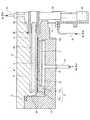
以下、前述の成膜方法を用いてシリコン酸化膜を成膜したときに回転テーブル2の上面、側面、下面等に堆積したシリコン酸化膜等の反応生成物を除去する場合を例に挙げて説明する。図6は、本発明の実施形態のクリーニング方法の一例を示すタイミングチャートである。図7及び図8は、図1の成膜装置の回転テーブルの昇降動作を説明するための概略断面図であり、図7は、回転テーブルを上昇させたときの状態を示し、図8は、回転テーブルを下降させたときの状態を示している。 Hereinafter, an example will be described in which a reaction product such as a silicon oxide film deposited on the upper surface, side surface, lower surface, etc. of the rotary table 2 is removed when a silicon oxide film is formed using the above-described film forming method. To do. FIG. 6 is a timing chart showing an example of the cleaning method according to the embodiment of the present invention. 7 and 8 are schematic cross-sectional views for explaining the lifting and lowering operation of the rotary table of the film forming apparatus of FIG. 1, FIG. 7 shows a state when the rotary table is raised, and FIG. The state when the rotary table is lowered is shown.
図6に示されるように、本発明の実施形態のクリーニング方法は、第1のパージ工程、第1のクリーニング工程、第2のクリーニング工程、及び第2のパージ工程を含み、これらの工程をこの順番に行うものである。なお、第1のパージ工程及び第2のパージ工程については、省略することも可能である。 As shown in FIG. 6, the cleaning method of the embodiment of the present invention includes a first purge process, a first cleaning process, a second cleaning process, and a second purge process, and these processes are performed in this process. In order. Note that the first purge step and the second purge step can be omitted.
まず、第1のパージ工程では、回転テーブル2の凹部2aにウエハWが載置されていない状態で、駆動部23により回転テーブル2をup位置へ移動させ、分離ガスノズル41、42、分離ガス供給管51及びパージガス供給管72、73からN2ガスを供給する。このとき、真空ポンプ64及び圧力制御器65により、真空容器1内を予め設定した圧力に維持する。これにより、真空容器1内がN2ガス雰囲気となる。First, in the first purge process, the rotary table 2 is moved to the up position by the
続いて、第1のクリーニング工程では、図7に示されるように、回転テーブル2をup位置で維持した状態で、所定の速度で回転させ、クリーニングガスノズル33から第1の処理領域P1にClF3ガスを供給する。第1の時間T1の経過後、ClF3ガスの供給を停止する。第1の時間T1は、回転テーブル2の上面、側面、下面等に堆積した反応生成物の膜厚に応じて定めることができる。Subsequently, in the first cleaning process, as shown in FIG. 7, the rotary table 2 is maintained at the up position, and is rotated at a predetermined speed, so that ClF3 is supplied from the cleaning
続いて、第2のクリーニング工程では、図8に示されるように、駆動部23により回転テーブル2をdown位置へ移動させ、down位置において所定の速度で回転させ、クリーニングガスノズル33から第1の処理領域P1にClF3ガスを供給する。down位置は、up位置よりも下方の位置である。第2の時間T2の経過後、ClF3ガスの供給を停止する。第2の時間T2は、回転テーブル2の上面、側面、下面等に堆積した反応生成物の膜厚に応じて定めることができる。Subsequently, in the second cleaning step, as shown in FIG. 8, the rotary table 2 is moved to the down position by the driving
続いて、第2のパージ工程では、回転テーブル2をdown位置に維持した状態で、分離ガスノズル41、42、分離ガス供給管51及びパージガス供給管72、73からN2ガスを供給する。このとき、真空ポンプ64及び圧力制御器65により、真空容器1内を予め設定した圧力に維持する。所定の時間の経過後、分離ガスノズル41、42、分離ガス供給管51及びパージガス供給管72、73からのN2ガスの供給を停止し、クリーニング処理を終了する。Subsequently, in the second purge step, N2 gas is supplied from the
本発明の実施形態に係るクリーニング方法では、回転テーブル2の上下方向の位置が異なる2つの位置(up位置及びdown位置)において、真空容器1内にクリーニングガスを供給して回転テーブル2の上面、側面、下面等のクリーニングを行う。up位置では、回転テーブル2の上面とクリーニングガスノズル33との間隔が狭いので、クリーニングガスノズル33から供給されるClF3ガスの流速を上げて回転テーブル2の上面に滞在する時間を短くすることができる。これにより、回転テーブル2の側面及び下面に堆積したシリコン酸化膜等の反応生成物のエッチング速度を高めることができる。down位置では、回転テーブル2の上面とクリーニングガスノズル33との間隔が広いので、クリーニングガスノズル33から供給されるClF3ガスの流速を下げて滞在時間を長くすることができる。これにより、回転テーブル2の上面に堆積したシリコン酸化膜等の反応生成物のエッチング速度を高めることができる。このように、up位置において回転テーブル2の側面及び下面に堆積したシリコン酸化膜等の反応生成物を効率よく除去し、かつ、down位置において回転テーブル2の上面に堆積したシリコン酸化膜等の反応生成物を効率よく除去することができる。その結果、クリーニング時間を短縮し、均一性の高いクリーニングを行うことができる。In the cleaning method according to the embodiment of the present invention, the cleaning table is supplied into the
また、回転テーブル2の上面に堆積したシリコン酸化膜等の反応生成物の堆積量と回転テーブル2の側面及び/又は下面に堆積したシリコン酸化膜等の反応生成物の堆積量とに基づいて、第1の時間T1と第2の時間T2との比率を決定することが好ましい。具体的には、回転テーブル2の上面に堆積したシリコン酸化膜等の反応生成物の堆積量が、回転テーブル2の側面及び/又は下面に堆積したシリコン酸化膜等の反応生成物の堆積量よりも多い場合、第2の時間T2を第1の時間T1よりも長くすることが好ましい。これに対し、回転テーブル2の側面及び/又は下面に堆積したシリコン酸化膜等の反応生成物の堆積量が、回転テーブル2の上面に堆積したシリコン酸化膜等の反応生成物の堆積量よりも多い場合、第1の時間T1を第2の時間T2よりも長くすることが好ましい。 Further, based on the deposition amount of the reaction product such as silicon oxide film deposited on the upper surface of the
また、第2のクリーニング工程では、分離ガス供給管51から供給されるN2ガスの流量を第1のクリーニング工程よりも小さくすることが好ましい。これにより、回転テーブル2の中心領域Cから第1の排気領域E1、第2の排気領域E2に向かって流れるクリーニングガスの流速が低くなる。このため、クリーニングガスが回転テーブル2の上面に滞在する時間が長くなり、回転テーブル2の上面に堆積したシリコン酸化膜等の反応生成物をより効率よく除去することができる。In the second cleaning step, it is preferable that the flow rate of the N2 gas supplied from the separation
上記の実施形態に係るクリーニング方法では、第1のクリーニング工程において、up位置でクリーニングを行い、次いで第2のクリーニング工程において、down位置でクリーニングを行う場合を例に挙げて説明したが、これに限定されるものではない。 In the cleaning method according to the above embodiment, the case where the cleaning is performed at the up position in the first cleaning step and the cleaning is performed at the down position in the second cleaning step is described as an example. It is not limited.
図9は、本発明の実施形態のクリーニング方法の別の例を示すタイミングチャートである。 FIG. 9 is a timing chart showing another example of the cleaning method according to the embodiment of the present invention.
本発明の実施形態に係るクリーニング方法では、例えば図9(a)に示されるように、第2のクリーニング工程の後、第1のクリーニング工程を行ってもよい。なお、第1のクリーニング工程は、回転テーブル2をup位置に維持した状態でクリーニングを行う工程である。また、第2のクリーニング工程は、回転テーブル2をdown位置に維持した状態でクリーニングを行う工程である。 In the cleaning method according to the embodiment of the present invention, for example, as shown in FIG. 9A, the first cleaning process may be performed after the second cleaning process. Note that the first cleaning step is a step of performing cleaning in a state where the rotary table 2 is maintained at the up position. The second cleaning step is a step of performing cleaning in a state where the
また、例えば図9(b)に示されるように、第1のクリーニング工程の後であって、第2のクリーニング工程の前に、第3のクリーニング工程を行ってもよい。なお、第3のクリーニング工程は、回転テーブル2をup位置からdown位置へ下降させながらクリーニングを行う工程である。 For example, as shown in FIG. 9B, a third cleaning step may be performed after the first cleaning step and before the second cleaning step. Note that the third cleaning step is a step of performing cleaning while lowering the rotary table 2 from the up position to the down position.
また、例えば図9(c)に示されるように、第2のクリーニング工程の後であって、第1のクリーニング工程の前に、第4のクリーニング工程を行ってもよい。なお、第4のクリーニング工程は、回転テーブル2をdown位置からup位置へ上昇させながらクリーニングを行う工程である。 For example, as shown in FIG. 9C, a fourth cleaning step may be performed after the second cleaning step and before the first cleaning step. The fourth cleaning step is a step of performing cleaning while raising the rotary table 2 from the down position to the up position.
また、例えば図9(d)に示されるように、第1のクリーニング工程と第2のクリーニング工程とを交互に繰り返し行ってもよい。 For example, as shown in FIG. 9D, the first cleaning process and the second cleaning process may be alternately repeated.
また、例えば図9(e)に示されるように、第1のクリーニング工程、第3のクリーニング工程、第2のクリーニング工程及び第4のクリーニング工程を、この順番に繰り返し行ってもよい。 Further, for example, as shown in FIG. 9E, the first cleaning process, the third cleaning process, the second cleaning process, and the fourth cleaning process may be repeated in this order.
以上、本発明を実施するための形態について説明したが、上記内容は、発明の内容を限定するものではなく、本発明の範囲内で種々の変形及び改良が可能である。 As mentioned above, although the form for implementing this invention was demonstrated, the said content does not limit the content of invention, Various deformation | transformation and improvement are possible within the scope of the present invention.
上記の実施形態では、成膜する膜がシリコン酸化膜である場合を例に挙げて説明したが、他の膜を成膜する場合にも、本発明の実施形態に係るクリーニング方法を適用することが可能である。 In the above embodiment, the case where the film to be formed is a silicon oxide film has been described as an example. However, the cleaning method according to the embodiment of the present invention is also applied to the case where another film is formed. Is possible.
上記の実施形態では、回転テーブル2上に載置した複数枚のウエハWに対して一括して成膜処理を行うセミバッチ式の成膜装置を例に挙げて説明したが、これに限定されない。例えば、ウエハボートに載置された多数枚のウエハWにより1つのバッチを構成し、1つのバッチ単位で成膜処理を行うバッチ式の成膜装置であってもよく、1枚ずつ成膜処理を行う枚葉式の成膜装置であってもよい。 In the above-described embodiment, the semi-batch type film forming apparatus that collectively performs the film forming process on the plurality of wafers W placed on the
1 真空容器
2 回転テーブル
2a 凹部
5 突出部
31 反応ガスノズル
32 反応ガスノズル
33 クリーニングガスノズル
51 分離ガス供給管
C 中心領域
D 分離領域
P1 第1の処理領域
P2 第2の処理領域
W ウエハDESCRIPTION OF
Claims (19)
Translated fromJapanese前記回転テーブルを、前記第1のクリーニング位置よりも下方である第2のクリーニング位置において回転させた状態で、前記回転テーブルの基板載置面の上方から前記クリーニングガスを供給する第2のクリーニング工程と、
を含む、
クリーニング方法。A first cleaning step of supplying a cleaning gas from above the substrate mounting surface of the rotary table in a state where the rotary table capable of mounting the substrate on the upper surface in the processing chamber is rotated at the first cleaning position;
A second cleaning step of supplying the cleaning gas from above the substrate mounting surface of the rotary table in a state where the rotary table is rotated at a second cleaning position which is lower than the first cleaning position; When,
including,
Cleaning method.
請求項1に記載のクリーニング方法。After the first cleaning step, the second cleaning step is performed.
The cleaning method according to claim 1.
請求項2に記載のクリーニング方法。After the first cleaning step and before the second cleaning step, the rotary table is rotated while being moved from the first cleaning position to the second cleaning position. A third cleaning step of supplying the cleaning gas from above the substrate mounting surface of the turntable;
The cleaning method according to claim 2.
請求項1に記載のクリーニング方法。After the second cleaning step, the first cleaning step is performed.
The cleaning method according to claim 1.
請求項4に記載のクリーニング方法。After the second cleaning step and before the first cleaning step, the rotary table is rotated while being moved from the second cleaning position to the first cleaning position. A fourth cleaning step of supplying the cleaning gas from above the substrate mounting surface of the turntable;
The cleaning method according to claim 4.
請求項1に記載のクリーニング方法。The first cleaning step and the second cleaning step are alternately repeated.
The cleaning method according to claim 1.
前記第2のクリーニング工程の後に、前記回転テーブルを、前記第2のクリーニング位置から前記第1のクリーニング位置に移動させながら回転させた状態で、前記回転テーブルの基板載置面の上方から前記クリーニングガスを供給する第4のクリーニング工程と、
を含み、
前記第1のクリーニング工程、前記第3のクリーニング工程、前記第2のクリーニング工程及び前記第4のクリーニング工程をこの順番に繰り返す、
請求項1に記載のクリーニング方法。After the first cleaning step, the cleaning table is rotated from above the substrate mounting surface of the rotating table in a state where the rotating table is rotated while being moved from the first cleaning position to the second cleaning position. A third cleaning step for supplying gas;
After the second cleaning step, the cleaning table is rotated from above the substrate mounting surface of the rotating table in a state where the rotating table is rotated while being moved from the second cleaning position to the first cleaning position. A fourth cleaning step of supplying gas;
Including
Repeating the first cleaning step, the third cleaning step, the second cleaning step, and the fourth cleaning step in this order;
The cleaning method according to claim 1.
請求項1乃至7のいずれか一項に記載のクリーニング方法。The cleaning gas includes ClF3 gas.
The cleaning method according to claim 1.
前記回転テーブルを、第1のクリーニング位置において回転させた状態で、前記回転テーブルの基板載置面の上方からクリーニングガスを供給する第1のクリーニング工程と、
前記回転テーブルを、前記第1のクリーニング位置よりも下方である第2のクリーニング位置において回転させた状態で、前記回転テーブルの基板載置面の上方から前記クリーニングガスを供給する第2のクリーニング工程と、
を含む、
クリーニング方法。A rotary table capable of placing a substrate on the upper surface in the processing chamber; a first processing region and a second processing region which are disposed above the rotary table and spaced apart from each other along the rotation direction of the rotary table; A separation region disposed between the processing region and the second processing region, and a protrusion projecting downward from the ceiling surface side in the processing chamber is provided in the separation region, and the separation region is provided. A ceiling surface lower than the first processing region and the second processing region is formed, and a cleaning gas can be supplied to the first processing region and / or the second processing region, and a purge gas can be supplied to the separation region. A cleaning method using a membrane device,
A first cleaning step of supplying a cleaning gas from above a substrate mounting surface of the rotary table in a state where the rotary table is rotated at a first cleaning position;
A second cleaning step of supplying the cleaning gas from above the substrate mounting surface of the rotary table in a state where the rotary table is rotated at a second cleaning position which is lower than the first cleaning position; When,
including,
Cleaning method.
前記第2のクリーニング工程は、前記中心領域から供給される分離ガスの流量を前記第1のクリーニング工程よりも小さくした状態で行う工程である、
請求項9に記載のクリーニング方法。A separation gas supply pipe located at the center of the processing chamber for separating the atmosphere of the first processing region and the second processing region and supplying a separation gas to the substrate mounting surface of the turntable Having a central area provided,
The second cleaning step is a step performed in a state in which the flow rate of the separation gas supplied from the central region is smaller than that in the first cleaning step.
The cleaning method according to claim 9.
前記成膜工程を繰り返すことにより、前記回転テーブルの上面に所定の膜厚の膜が成膜されたときに前記第1のクリーニング工程及び前記第2のクリーニング工程を行う、
請求項9又は10に記載のクリーニング方法。The first reaction is performed by rotating the rotary table in a state where the first reaction gas is supplied to the first processing region, the second reaction gas is supplied to the second processing region, and the purge gas is supplied to the separation region. A film forming step of forming a reaction product of a gas and the second reaction gas on a substrate;
By repeating the film forming step, the first cleaning step and the second cleaning step are performed when a film having a predetermined film thickness is formed on the upper surface of the turntable.
The cleaning method according to claim 9 or 10.
請求項11に記載のクリーニング方法。The predetermined film is a silicon oxide film,
The cleaning method according to claim 11.
請求項9乃至12のいずれか一項に記載のクリーニング方法。After the first cleaning step, the second cleaning step is performed.
The cleaning method according to any one of claims 9 to 12.
請求項13に記載のクリーニング方法。After the first cleaning step and before the second cleaning step, the rotary table is rotated while being moved from the first cleaning position to the second cleaning position. A third cleaning step of supplying the cleaning gas from above the substrate mounting surface of the turntable;
The cleaning method according to claim 13.
請求項9乃至12のいずれか一項に記載のクリーニング方法。After the second cleaning step, the first cleaning step is performed.
The cleaning method according to any one of claims 9 to 12.
請求項15に記載のクリーニング方法。After the second cleaning step and before the first cleaning step, the rotary table is rotated while being moved from the second cleaning position to the first cleaning position. A fourth cleaning step of supplying the cleaning gas from above the substrate mounting surface of the turntable;
The cleaning method according to claim 15.
請求項9乃至12のいずれか一項に記載のクリーニング方法。The first cleaning step and the second cleaning step are alternately repeated.
The cleaning method according to any one of claims 9 to 12.
前記第2のクリーニング工程の後に、前記回転テーブルを、前記第2のクリーニング位置から前記第1のクリーニング位置に移動させながら回転させた状態で、前記回転テーブルの基板載置面の上方から前記クリーニングガスを供給する第4のクリーニング工程と、
を含み、
前記第1のクリーニング工程、前記第3のクリーニング工程、前記第2のクリーニング工程及び前記第4のクリーニング工程をこの順番に繰り返す、
請求項9乃至12のいずれか一項に記載のクリーニング方法。After the first cleaning step, the cleaning table is rotated from above the substrate mounting surface of the rotating table in a state where the rotating table is rotated while being moved from the first cleaning position to the second cleaning position. A third cleaning step for supplying gas;
After the second cleaning step, the cleaning table is rotated from above the substrate mounting surface of the rotating table in a state where the rotating table is rotated while being moved from the second cleaning position to the first cleaning position. A fourth cleaning step of supplying gas;
Including
Repeating the first cleaning step, the third cleaning step, the second cleaning step, and the fourth cleaning step in this order;
The cleaning method according to any one of claims 9 to 12.
請求項9乃至18のいずれか一項に記載のクリーニング方法。The cleaning gas includes ClF3 gas.
The cleaning method according to any one of claims 9 to 18.
Priority Applications (5)
| Application Number | Priority Date | Filing Date | Title |
|---|---|---|---|
| JP2016237074AJP6749225B2 (en) | 2016-12-06 | 2016-12-06 | Cleaning method |
| US15/825,611US10648076B2 (en) | 2016-12-06 | 2017-11-29 | Cleaning method and film deposition apparatus executing the cleaning method for uniformly cleaning rotary table |
| KR1020170164222AKR102170612B1 (en) | 2016-12-06 | 2017-12-01 | Cleaning method |
| TW106142334ATWI695442B (en) | 2016-12-06 | 2017-12-04 | Cleaning method |
| CN201711277807.XACN108149221B (en) | 2016-12-06 | 2017-12-06 | Cleaning method |
Applications Claiming Priority (1)
| Application Number | Priority Date | Filing Date | Title |
|---|---|---|---|
| JP2016237074AJP6749225B2 (en) | 2016-12-06 | 2016-12-06 | Cleaning method |
Publications (2)
| Publication Number | Publication Date |
|---|---|
| JP2018093121Atrue JP2018093121A (en) | 2018-06-14 |
| JP6749225B2 JP6749225B2 (en) | 2020-09-02 |
Family
ID=62240866
Family Applications (1)
| Application Number | Title | Priority Date | Filing Date |
|---|---|---|---|
| JP2016237074AActiveJP6749225B2 (en) | 2016-12-06 | 2016-12-06 | Cleaning method |
Country Status (5)
| Country | Link |
|---|---|
| US (1) | US10648076B2 (en) |
| JP (1) | JP6749225B2 (en) |
| KR (1) | KR102170612B1 (en) |
| CN (1) | CN108149221B (en) |
| TW (1) | TWI695442B (en) |
Cited By (2)
| Publication number | Priority date | Publication date | Assignee | Title |
|---|---|---|---|---|
| JP2020010001A (en)* | 2018-07-12 | 2020-01-16 | 東京エレクトロン株式会社 | Cleaning method and substrate processing apparatus |
| WO2024196580A1 (en)* | 2023-03-21 | 2024-09-26 | Lam Research Corporation | Chamber cleaning for substrate processing systems |
Families Citing this family (6)
| Publication number | Priority date | Publication date | Assignee | Title |
|---|---|---|---|---|
| JP6956660B2 (en)* | 2018-03-19 | 2021-11-02 | 東京エレクトロン株式会社 | Cleaning method and film forming equipment |
| JP7042689B2 (en)* | 2018-05-23 | 2022-03-28 | 東京エレクトロン株式会社 | Dry cleaning method of susceptor and substrate processing equipment |
| KR102081706B1 (en)* | 2018-07-18 | 2020-02-27 | 세메스 주식회사 | Method for treating a substrate and an apparatus for treating a substrate |
| KR102620219B1 (en) | 2018-11-02 | 2024-01-02 | 삼성전자주식회사 | Substrate processing method and substrate processing apparatus |
| CN113637950A (en)* | 2021-08-17 | 2021-11-12 | 浙江海顺新材料有限公司 | Production device and production method of ultrathin aluminum layer PET aluminized film |
| CN114242626B (en)* | 2021-12-21 | 2022-04-29 | 智程半导体设备科技(昆山)有限公司 | Dry-method wafer cleaning equipment |
Citations (3)
| Publication number | Priority date | Publication date | Assignee | Title |
|---|---|---|---|---|
| KR20100056273A (en)* | 2008-11-19 | 2010-05-27 | 주식회사 아이피에스 | Apparatus for depositing thin film on wafer and method for cleaning the apparatus |
| JP2013201317A (en)* | 2012-03-26 | 2013-10-03 | Toyota Central R&D Labs Inc | Surface treatment device |
| JP2014017322A (en)* | 2012-07-06 | 2014-01-30 | Tokyo Electron Ltd | Deposition apparatus operation method and deposition apparatus |
Family Cites Families (21)
| Publication number | Priority date | Publication date | Assignee | Title |
|---|---|---|---|---|
| US4786352A (en)* | 1986-09-12 | 1988-11-22 | Benzing Technologies, Inc. | Apparatus for in-situ chamber cleaning |
| JP3274389B2 (en)* | 1996-08-12 | 2002-04-15 | 株式会社東芝 | Semiconductor substrate cleaning method |
| US5788778A (en)* | 1996-09-16 | 1998-08-04 | Applied Komatsu Technology, Inc. | Deposition chamber cleaning technique using a high power remote excitation source |
| JPH11283950A (en)* | 1998-03-30 | 1999-10-15 | Ebara Corp | Substrate cleaner |
| JP2002009035A (en)* | 2000-06-26 | 2002-01-11 | Toshiba Corp | Substrate cleaning method and substrate cleaning apparatus |
| US20030216041A1 (en)* | 2002-05-08 | 2003-11-20 | Herring Robert B. | In-situ thermal chamber cleaning |
| US20040093679A1 (en)* | 2002-11-15 | 2004-05-20 | Jay Kukoff | Scrubbing sponge with indicia and method of making same |
| US6919101B2 (en)* | 2003-02-04 | 2005-07-19 | Tegal Corporation | Method to deposit an impermeable film on porous low-k dielectric film |
| US20090047447A1 (en)* | 2005-08-02 | 2009-02-19 | Sawin Herbert H | Method for removing surface deposits and passivating interior surfaces of the interior of a chemical vapor deposition reactor |
| JP2007053154A (en)* | 2005-08-16 | 2007-03-01 | Pre-Tech Co Ltd | Cleaning device for mask substrate, and cleaning method for mask substrate using the device |
| KR100753158B1 (en) | 2006-06-19 | 2007-08-30 | 삼성전자주식회사 | How to Clean Process Chamber |
| CN101796215A (en)* | 2007-07-17 | 2010-08-04 | 应用材料股份有限公司 | Improved Cleaning Rates with Pressure-Controlled Remote Plasma Sources |
| EP2159304A1 (en)* | 2008-08-27 | 2010-03-03 | Nederlandse Organisatie voor toegepast- natuurwetenschappelijk onderzoek TNO | Apparatus and method for atomic layer deposition |
| JP5031013B2 (en) | 2008-11-19 | 2012-09-19 | 東京エレクトロン株式会社 | Film forming apparatus, film forming apparatus cleaning method, program, and computer-readable storage medium storing program |
| JP2010251705A (en)* | 2009-03-24 | 2010-11-04 | Nuflare Technology Inc | Film forming apparatus and film forming method |
| US20120000490A1 (en) | 2010-07-01 | 2012-01-05 | Applied Materials, Inc. | Methods for enhanced processing chamber cleaning |
| JP5632860B2 (en)* | 2012-01-05 | 2014-11-26 | 東京エレクトロン株式会社 | Substrate cleaning method, substrate cleaning apparatus, and substrate cleaning storage medium |
| WO2013146278A1 (en) | 2012-03-30 | 2013-10-03 | 株式会社日立国際電気 | Semiconductor device manufacturing method, substrate processing method, and substrate processing apparatus |
| US20140069459A1 (en) | 2012-09-09 | 2014-03-13 | Novellus Systems, Inc. | Methods and apparatus for cleaning deposition chambers |
| JP6086763B2 (en)* | 2013-03-11 | 2017-03-01 | ファスフォードテクノロジ株式会社 | Collet cleaning method and die bonder using the same |
| NL2014497B1 (en)* | 2015-03-20 | 2017-01-19 | Asm Int Nv | Method for cleaning deposition apparatus. |
- 2016
- 2016-12-06JPJP2016237074Apatent/JP6749225B2/enactiveActive
- 2017
- 2017-11-29USUS15/825,611patent/US10648076B2/enactiveActive
- 2017-12-01KRKR1020170164222Apatent/KR102170612B1/enactiveActive
- 2017-12-04TWTW106142334Apatent/TWI695442B/enactive
- 2017-12-06CNCN201711277807.XApatent/CN108149221B/enactiveActive
Patent Citations (3)
| Publication number | Priority date | Publication date | Assignee | Title |
|---|---|---|---|---|
| KR20100056273A (en)* | 2008-11-19 | 2010-05-27 | 주식회사 아이피에스 | Apparatus for depositing thin film on wafer and method for cleaning the apparatus |
| JP2013201317A (en)* | 2012-03-26 | 2013-10-03 | Toyota Central R&D Labs Inc | Surface treatment device |
| JP2014017322A (en)* | 2012-07-06 | 2014-01-30 | Tokyo Electron Ltd | Deposition apparatus operation method and deposition apparatus |
Cited By (7)
| Publication number | Priority date | Publication date | Assignee | Title |
|---|---|---|---|---|
| JP2020010001A (en)* | 2018-07-12 | 2020-01-16 | 東京エレクトロン株式会社 | Cleaning method and substrate processing apparatus |
| WO2020013014A1 (en)* | 2018-07-12 | 2020-01-16 | 東京エレクトロン株式会社 | Cleaning method and substrate processing device |
| KR20210027456A (en)* | 2018-07-12 | 2021-03-10 | 도쿄엘렉트론가부시키가이샤 | Cleaning method and substrate processing apparatus |
| JP7038618B2 (en) | 2018-07-12 | 2022-03-18 | 東京エレクトロン株式会社 | Cleaning method and substrate processing equipment |
| US11517943B2 (en) | 2018-07-12 | 2022-12-06 | Tokyo Electron Limited | Cleaning method and substrate processing apparatus |
| KR102584068B1 (en)* | 2018-07-12 | 2023-09-27 | 도쿄엘렉트론가부시키가이샤 | Cleaning method and substrate processing device |
| WO2024196580A1 (en)* | 2023-03-21 | 2024-09-26 | Lam Research Corporation | Chamber cleaning for substrate processing systems |
Also Published As
| Publication number | Publication date |
|---|---|
| CN108149221B (en) | 2021-06-25 |
| KR20180064983A (en) | 2018-06-15 |
| US10648076B2 (en) | 2020-05-12 |
| JP6749225B2 (en) | 2020-09-02 |
| TWI695442B (en) | 2020-06-01 |
| TW201832306A (en) | 2018-09-01 |
| KR102170612B1 (en) | 2020-10-27 |
| CN108149221A (en) | 2018-06-12 |
| US20180155829A1 (en) | 2018-06-07 |
Similar Documents
| Publication | Publication Date | Title |
|---|---|---|
| JP6749225B2 (en) | Cleaning method | |
| TWI579954B (en) | Substrate processing apparatus and method for processing a substrate | |
| CN112962084B (en) | Substrate processing apparatus | |
| JP5107185B2 (en) | Film forming apparatus, substrate processing apparatus, film forming method, and recording medium recording program for executing this film forming method | |
| JP4668286B2 (en) | Processing equipment | |
| TWI514507B (en) | Substrate processing apparatus | |
| JP6478847B2 (en) | Substrate processing equipment | |
| US20110312188A1 (en) | Processing apparatus and film forming method | |
| US11214864B2 (en) | Method for reducing metal contamination and film deposition apparatus | |
| TWI601232B (en) | Support structure and processing apparatus | |
| JP6747220B2 (en) | Substrate processing apparatus and substrate processing method | |
| KR102491924B1 (en) | Film forming method and film forming apparatus | |
| JP6906439B2 (en) | Film formation method | |
| JP3221102U (en) | Seal structure and processing device | |
| JP5708843B2 (en) | Support structure and processing apparatus | |
| JP6096588B2 (en) | Substrate processing apparatus and substrate processing method | |
| JP2004011005A (en) | Treatment apparatus treatment method | |
| JP7753727B2 (en) | Apparatus for forming a film on a substrate and method for forming a film on a substrate | |
| US20240209508A1 (en) | Deposition apparatus and processing method | |
| US20230068938A1 (en) | Film forming apparatus and film forming method | |
| JP6739370B2 (en) | Substrate processing equipment |
Legal Events
| Date | Code | Title | Description |
|---|---|---|---|
| A621 | Written request for application examination | Free format text:JAPANESE INTERMEDIATE CODE: A621 Effective date:20190520 | |
| A977 | Report on retrieval | Free format text:JAPANESE INTERMEDIATE CODE: A971007 Effective date:20200228 | |
| A131 | Notification of reasons for refusal | Free format text:JAPANESE INTERMEDIATE CODE: A131 Effective date:20200310 | |
| A521 | Request for written amendment filed | Free format text:JAPANESE INTERMEDIATE CODE: A523 Effective date:20200424 | |
| TRDD | Decision of grant or rejection written | ||
| A01 | Written decision to grant a patent or to grant a registration (utility model) | Free format text:JAPANESE INTERMEDIATE CODE: A01 Effective date:20200714 | |
| A61 | First payment of annual fees (during grant procedure) | Free format text:JAPANESE INTERMEDIATE CODE: A61 Effective date:20200811 | |
| R150 | Certificate of patent or registration of utility model | Ref document number:6749225 Country of ref document:JP Free format text:JAPANESE INTERMEDIATE CODE: R150 | |
| R250 | Receipt of annual fees | Free format text:JAPANESE INTERMEDIATE CODE: R250 | |
| R250 | Receipt of annual fees | Free format text:JAPANESE INTERMEDIATE CODE: R250 | |
| R250 | Receipt of annual fees | Free format text:JAPANESE INTERMEDIATE CODE: R250 |