JP2018089859A - Information processing apparatus, modeling apparatus, modeling system, method, and program - Google Patents
Information processing apparatus, modeling apparatus, modeling system, method, and programDownload PDFInfo
- Publication number
- JP2018089859A JP2018089859AJP2016235385AJP2016235385AJP2018089859AJP 2018089859 AJP2018089859 AJP 2018089859AJP 2016235385 AJP2016235385 AJP 2016235385AJP 2016235385 AJP2016235385 AJP 2016235385AJP 2018089859 AJP2018089859 AJP 2018089859A
- Authority
- JP
- Japan
- Prior art keywords
- modeling
- information
- material body
- modeling material
- correction
- Prior art date
- Legal status (The legal status is an assumption and is not a legal conclusion. Google has not performed a legal analysis and makes no representation as to the accuracy of the status listed.)
- Pending
Links
Images


Classifications
- B—PERFORMING OPERATIONS; TRANSPORTING
- B29—WORKING OF PLASTICS; WORKING OF SUBSTANCES IN A PLASTIC STATE IN GENERAL
- B29C—SHAPING OR JOINING OF PLASTICS; SHAPING OF MATERIAL IN A PLASTIC STATE, NOT OTHERWISE PROVIDED FOR; AFTER-TREATMENT OF THE SHAPED PRODUCTS, e.g. REPAIRING
- B29C64/00—Additive manufacturing, i.e. manufacturing of three-dimensional [3D] objects by additive deposition, additive agglomeration or additive layering, e.g. by 3D printing, stereolithography or selective laser sintering
- B29C64/30—Auxiliary operations or equipment
- B29C64/386—Data acquisition or data processing for additive manufacturing
- B29C64/393—Data acquisition or data processing for additive manufacturing for controlling or regulating additive manufacturing processes
- B—PERFORMING OPERATIONS; TRANSPORTING
- B33—ADDITIVE MANUFACTURING TECHNOLOGY
- B33Y—ADDITIVE MANUFACTURING, i.e. MANUFACTURING OF THREE-DIMENSIONAL [3-D] OBJECTS BY ADDITIVE DEPOSITION, ADDITIVE AGGLOMERATION OR ADDITIVE LAYERING, e.g. BY 3-D PRINTING, STEREOLITHOGRAPHY OR SELECTIVE LASER SINTERING
- B33Y50/00—Data acquisition or data processing for additive manufacturing
- B33Y50/02—Data acquisition or data processing for additive manufacturing for controlling or regulating additive manufacturing processes
- G—PHYSICS
- G05—CONTROLLING; REGULATING
- G05B—CONTROL OR REGULATING SYSTEMS IN GENERAL; FUNCTIONAL ELEMENTS OF SUCH SYSTEMS; MONITORING OR TESTING ARRANGEMENTS FOR SUCH SYSTEMS OR ELEMENTS
- G05B19/00—Programme-control systems
- G05B19/02—Programme-control systems electric
- G05B19/18—Numerical control [NC], i.e. automatically operating machines, in particular machine tools, e.g. in a manufacturing environment, so as to execute positioning, movement or co-ordinated operations by means of programme data in numerical form
- G05B19/4097—Numerical control [NC], i.e. automatically operating machines, in particular machine tools, e.g. in a manufacturing environment, so as to execute positioning, movement or co-ordinated operations by means of programme data in numerical form characterised by using design data to control NC machines, e.g. CAD/CAM
- G05B19/4099—Surface or curve machining, making 3D objects, e.g. desktop manufacturing
- G—PHYSICS
- G05—CONTROLLING; REGULATING
- G05B—CONTROL OR REGULATING SYSTEMS IN GENERAL; FUNCTIONAL ELEMENTS OF SUCH SYSTEMS; MONITORING OR TESTING ARRANGEMENTS FOR SUCH SYSTEMS OR ELEMENTS
- G05B2219/00—Program-control systems
- G05B2219/30—Nc systems
- G05B2219/49—Nc machine tool, till multiple
- G05B2219/49018—Laser sintering of powder in layers, selective laser sintering SLS
- G—PHYSICS
- G05—CONTROLLING; REGULATING
- G05B—CONTROL OR REGULATING SYSTEMS IN GENERAL; FUNCTIONAL ELEMENTS OF SUCH SYSTEMS; MONITORING OR TESTING ARRANGEMENTS FOR SUCH SYSTEMS OR ELEMENTS
- G05B2219/00—Program-control systems
- G05B2219/30—Nc systems
- G05B2219/49—Nc machine tool, till multiple
- G05B2219/49023—3-D printing, layer of powder, add drops of binder in layer, new powder
Landscapes
- Engineering & Computer Science (AREA)
- Manufacturing & Machinery (AREA)
- Chemical & Material Sciences (AREA)
- Materials Engineering (AREA)
- Physics & Mathematics (AREA)
- Human Computer Interaction (AREA)
- General Physics & Mathematics (AREA)
- Automation & Control Theory (AREA)
- Mechanical Engineering (AREA)
- Optics & Photonics (AREA)
Abstract
Translated fromJapaneseDescription
Translated fromJapanese本発明は、情報処理装置、造形装置、造形システム、方法及びプログラムに関する。 The present invention relates to an information processing apparatus, a modeling apparatus, a modeling system, a method, and a program.
従来、造形装置(AM(Additive Manufacturing)装置や3Dプリンタなどと呼ばれる)の登場により、試作品や小ロットの部品を低コスト、短納期で製作することが可能になってきている。造形装置で造形を行う場合には、事前に、三次元立体モデルのデータをCAM(Computer Aided Manufacturing)に取り込み、造形装置が理解可能な造形用のデータ(造形データ)を生成するのが一般的である。例えば熱溶解積層方式(FDM)により造形を行う場合、三次元立体モデルを層状にスライスしたデータを生成し、そのデータから層単位の造形手順(工作手順)を示す造形データを生成する。各層の造形手順には、造形ヘッドをどのような経路で動かし、造形ヘッドのノズルからどれだけの量の造形材料(例えば樹脂など)を何℃で押し出すかなどを造形装置に命令するGコードに代表される命令情報が含まれる。 Conventionally, with the advent of modeling apparatuses (referred to as AM (Additive Manufacturing) apparatuses and 3D printers), it has become possible to produce prototypes and small lot parts at low cost and with short delivery times. When modeling with a modeling apparatus, it is common to import data of a three-dimensional model into CAM (Computer Aided Manufacturing) in advance and generate modeling data (modeling data) that the modeling apparatus can understand. It is. For example, when modeling is performed by a hot melt lamination method (FDM), data obtained by slicing a three-dimensional solid model into layers is generated, and modeling data indicating a modeling procedure (work procedure) in units of layers is generated from the data. The G code for instructing the modeling device to move the modeling head and how much molding material (for example, resin) should be pushed out from the nozzle of the modeling head Representative command information is included.
3次元物体を一層ずつ積層していく立体造形方法において、材料の厚さのばらつきや寸法精度を良くするための方法を開示したものなどがある(例えば特許文献1参照)。 Among three-dimensional modeling methods in which three-dimensional objects are laminated one by one, there are methods that disclose methods for improving material thickness variation and dimensional accuracy (see, for example, Patent Document 1).
しかし、造形材料は材料の種別によって溶解温度や粘性などの特性が異なる。造形装置において同じ三次元立体モデルの造形を造形材料だけを変更して行う場合には、変更後の造形材料の特性に合わせて命令情報(主にパラメータ値)を変える必要がある。つまり、1つの三次元立体モデルについて造形材料を変更したものを造形する場合、造形材料の変更数分の造形データを新たに生成する必要がある。造形データの生成には時間やユーザの手間を要するため、ユーザにとって造形材料分の造形データの生成は作業負担が大きいという問題があった。 However, characteristics such as melting temperature and viscosity differ depending on the type of material. When modeling the same three-dimensional model in the modeling apparatus by changing only the modeling material, it is necessary to change the command information (mainly parameter values) in accordance with the characteristics of the modeling material after the change. That is, when modeling what changed the modeling material about one three-dimensional solid model, it is necessary to newly generate modeling data for the number of changes of the modeling material. Since generation of modeling data requires time and user's trouble, there is a problem that generation of modeling data for modeling material is heavy for the user.
本発明は、上記に鑑みてなされたものであって、1つの造形データから他の造形材料に適合する造形データを生成することが可能な情報処理装置、造形装置、造形システム、方法及びプログラムを提供することを目的とする。 The present invention has been made in view of the above, and includes an information processing apparatus, a modeling apparatus, a modeling system, a method, and a program capable of generating modeling data suitable for another modeling material from one modeling data. The purpose is to provide.
上述した課題を解決するために、発明の一実施の形態の情報処理装置は、造形装置に対して第1の造形材料体についての造形手順を実行させる命令情報を読み込む読込手段と、第2の造形材料体についての造形材料体情報を記憶する記憶手段と、上記読込手段により読み込まれた上記命令情報に含まれる、上記第1の造形材料体についての第1のパラメータ値を、上記記憶手段により記憶されている上記造形材料体情報に基づいて補正する補正手段と、を有する。 In order to solve the above-described problem, an information processing apparatus according to an embodiment of the present invention includes a reading unit that reads command information that causes a modeling apparatus to execute a modeling procedure for a first modeling material body; A storage means for storing modeling material body information about the modeling material body, and a first parameter value for the first modeling material body included in the command information read by the reading means by the storage means. Correction means for correcting based on the stored modeling material body information.
本発明によれば、1つの造形データから他の造形材料に適合する造形データを生成することが可能になるという効果を奏する。 According to this invention, there exists an effect that it becomes possible to produce | generate the modeling data which suits another modeling material from one modeling data.
以下、添付図面を参照しながら、本発明に係る情報処理装置、造形装置、造形システム、方法及びプログラムの実施の形態を詳細に説明する。なお、以下では、熱溶解積層方式(FDM)の造形装置を対象とする例を示す。 Hereinafter, embodiments of an information processing apparatus, a modeling apparatus, a modeling system, a method, and a program according to the present invention will be described in detail with reference to the accompanying drawings. In addition, below, the example which targets the modeling apparatus of a hot melt lamination system (FDM) is shown.
(第1の実施の形態)
図1は、本実施の形態に係る「造形システム」のシステム構成の一例を示す図である。図1に一例として示す造形システムX1は、情報処理装置1と造形装置2とを含むようにして構成される。情報処理装置1は、CAM(Computer Aided Manufacturing)処理手段1−1と補正処理手段1−2とを有し、造形装置2は、造形処理手段20を有する。「補正処理手段1−2」が「読込手段」と「補正手段」に対応する。(First embodiment)
FIG. 1 is a diagram illustrating an example of a system configuration of a “modeling system” according to the present embodiment. A modeling system X1 shown as an example in FIG. 1 is configured to include an
CAM処理手段1−1は、従来方式のCAM処理により、三次元立体モデルのデータから、造形装置2が理解可能な造形用のデータ(「造形データ」と呼ぶ)を生成する手段である。例えば、CAM処理手段1−1は、三次元立体モデルを三次元データ上で所定の方向からスライスし、スライスにより得られた各層について、指定された造形材料体で埋めるときの手順(造形手順)を示す命令情報をコマンドとパラメータを組み合わせて生成し、下層から上層に向けての各層の造形データを生成する。 The CAM processing unit 1-1 is a unit that generates data for modeling (referred to as “modeling data”) that can be understood by the
補正処理手段1−2は、CAM処理手段1−1で生成された造形データから、当該造形データの生成時の造形材料体とは異なる種別の造形材料体に対応する造形データに補正処理する手段である。 The correction processing unit 1-2 corrects the modeling data generated by the CAM processing unit 1-1 into modeling data corresponding to a type of modeling material body different from the modeling material body at the time of generation of the modeling data. It is.
造形処理手段20は、セットされている造形材料体を使用し、当該造形材料体に対応する造形データに従って三次元立体モデルを造形する手段である。例えば、造形処理手段20は、造形データに含まれるコマンドを実行し、下層から上層にかけ、層毎に、造形ヘッドの加熱や造形材料体の押し出しなどを行いながら造形ヘッドを走査する。各層は、順次上に積み上げられるため、三次元立体モデルが造形される。 The
(ハードウェア構成)
図2は、情報処理装置1のハードウェア構成の一例を示す図である。図2に示すように、情報処理装置1は、CPU(Central Processing Unit)100と、ROM(Read Only Memory)101と、RAM(Random Access Memory)102と、HDD(Hard Disk Drive)103と、キーボード105と、マウス106と、表示ディスプレイ107と、メディアドライブ108と、USBI/F110と、ネットワークI/F111とを有する。各部はシステムバス112を介して相互に接続されている。(Hardware configuration)
FIG. 2 is a diagram illustrating an example of a hardware configuration of the
CPU100は、プログラムを実行して情報処理装置1全体を統括的に制御する。ROM101は、BIOS(Basic Input/Output System)などを記憶する。RAM102は、CPU100がプログラムを実行する際のワーク領域などとして使用される。 The
HDD103は、ハードディスク104を制御し、各種プログラムやデータの読み取りや書き込みを行う。HDD103とハードディスク104は「記憶手段」の一例である。上記各種プログラムには、OS(Operating System)や、造形データの出力処理を行うアプリケーションプログラムなどが含まれる。上記データには、「対応情報」の一例の「ノズル情報D1(図5参照)」や、「造形材料体情報」の一例の「材料プロファイル(情報)D2(図6参照)」などが含まれる。造形データの出力処理にかかるプログラムの機能構成や、「ノズル情報D1」のデータ構成や、「材料プロファイルD2」のデータ構成については後述する。 The HDD 103 controls the
キーボード105とマウス106は、それぞれ、ユーザによる入力操作を受け付け、入力操作に対応する操作信号をCPU100に通知する。 Each of the keyboard 105 and the
表示ディスプレイ107は、LCD(Liquid Crystal Display)などであり、CPU100から出力された表示情報を表示する。 The display 107 is an LCD (Liquid Crystal Display) or the like, and displays display information output from the
メディアドライブ108は、記録メディア109の電気的な接続により、記録メディア109を対象にプログラムやデータの読み取りや書き込みを行う。 The media drive 108 reads and writes programs and data for the recording medium 109 by electrical connection of the recording medium 109.
USBI/F110は、ホストとUSB(Universal Serial Bus)通信するためのインタフェースである。なお、接続はUSBに限定しない。また、有線に限らず無線であっても良い。 The USB I / F 110 is an interface for performing USB (Universal Serial Bus) communication with a host. The connection is not limited to USB. Moreover, it is not limited to a wire and may be wireless.
ネットワークI/F111は、LAN(Local Area Network)等の通信ネットワークに接続するためのインタフェース(例えばEthernet(登録商標)カードなど)である。 The network I /
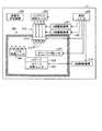
図3は、造形装置2のハードウェア構成の一例を示す図である。図3に示すように、造形装置2は、本体フレーム内部に、制御ユニット200や、造形ヘッド210や、チャンバー203や、装置内冷却装置208などを備えている。 FIG. 3 is a diagram illustrating an example of a hardware configuration of the
制御ユニット200は、造形装置2全体の制御を司る。 The
造形ヘッド210は、X軸駆動機構201とY軸駆動機構202とにより水平面内のX軸方向とY軸方向とへ移動可能に設けられ、ヘッド加熱ユニット214とノズル215とを有する。ヘッド加熱ユニット214は、造形ヘッド210を加熱してフィラメントを溶解する。ノズル215は、フィラメントを吐出するためのものでありノズル215毎に吐出口を有する。ヘッド加熱ユニット214とノズル215はチャンバー203の内部側に設けられている。フィラメント供給ユニット206は、造形ヘッド210に対してフィラメントを供給する。フィラメントは、造形材料の一形態であり、例えば熱可塑性樹脂を原料として固められている。フィラメントは、フィラメント供給ユニット206において巻回されているものから端部が引き出され、造形ヘッド210の各ノズル215の吐出口へと導かれている。 The
チャンバー203内部には、ステージ204や、ステージ加熱ユニット205、チャンバー用ヒータ207などが設けられている。ステージ204は、Z軸駆動機構216により積層方向となるZ軸方向へ昇降可能に設けられている。フィラメントは、ノズル215からステージ204上に配置するビルドプレート(不図示)上に向けてプーリー(不図示)の回転などにより押し出され、ビルドプレート上で層状に積み上げられて三次元立体像が造形される。ステージ加熱ユニット205は、ステージ204を介してビルドプレートを加熱するためのものである。チャンバー用ヒータ207は、チャンバー203内部の温度を制御するためのものである。なお、チャンバー203内部にノズル清掃ユニット209が設けられているが、ノズル215を清掃するためにある。また、装置内冷却装置208は、装置内を冷却するためにある。装置内冷却装置208やノズル清掃ユニット209についての説明はここまでとする。 Inside the
図4は、制御ユニット200のハードウェア構成の一例を示す図である。図4に示すように、制御ユニット200は、CPU250と、ROM251と、RAM252と、ネットワークI/F253と、USBI/F254と、メディアドライブ255と、入出力I/F256とを有する。各部はシステムバス257を介して相互に接続されている。 FIG. 4 is a diagram illustrating an example of a hardware configuration of the
CPU250は、プログラムを実行して造形装置2全体を統括的に制御する。ROM251は、固定プログラムを記憶する。RAM252は、CPU250がプログラムを実行する際のワーク領域などとして使用される。 The
入出力I/F256は、造形装置2の各部との間で入出力を行う。ここで、図4に示すX軸ポジション検知機構211、Y軸ポジション検知機構212、及びZ軸ポジション検知機構213は、図3において図示を省略したものである。 The input / output I / F 256 performs input / output with each unit of the
ネットワークI/F253は、LAN(Local Area Network)等の通信ネットワークに接続するためのインタフェース(例えばEthernet(登録商標)カードなど)である。 The network I /
USBI/F254は、ホストとUSB通信するためのインタフェースである。なお、接続はUSBに限定しない。また、有線に限らず無線であっても良い。 The USB I /
メディアドライブ255は、記録メディア109(図2参照)の電気的な接続により、記録メディア109を対象にプログラムやデータの読み取りや書き込みを行う。 The media drive 255 reads and writes programs and data for the recording medium 109 by electrical connection of the recording medium 109 (see FIG. 2).
(データ構成)
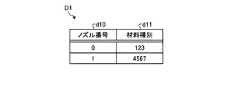
図5は、ノズル情報D1のデータ構成の一例を示す図である。図5に示すように、ノズル情報D1は、ノズル番号情報d10と材料種別情報d11とが対応付けられたものである。(Data structure)
FIG. 5 is a diagram illustrating an example of a data configuration of the nozzle information D1. As shown in FIG. 5, the nozzle information D1 is obtained by associating nozzle number information d10 and material type information d11.
ノズル番号情報d10は「ノズルの識別情報」の一例である。ノズル番号情報d10には、造形装置2が備える各ノズル215のノズル番号(0、1、・・・)が設定されている。 The nozzle number information d10 is an example of “nozzle identification information”. In the nozzle number information d10, the nozzle number (0, 1,...) Of each
材料種別情報d11は、造形材料(本実施の形態ではフィラメント)の材料種別を識別する識別情報である。図5には一例としてユニーク番号を付している。 The material type information d11 is identification information for identifying the material type of the modeling material (filament in the present embodiment). In FIG. 5, a unique number is given as an example.
図6は、材料プロファイルD2のデータ構成の一例を示す図である。図6の材料プロファイルD2の、項目k1は、材料プロファイルD2に設定されているパラメータ値の項目を示す欄であり、データd20とデータd21は、それぞれ、材料名「ABS」と材料名「PLA」についてのパラメータ値が設定された、材料プロファイルの設定データである。ここでは、一例として、ABS樹脂とPLA樹脂の2材料種別の材料プロファイルを示しているが、材料種別の種類や数をこれらに限定するものではない。例えば樹脂以外の材料に変更するなど、材料種別の種類や数は適宜決めても良い。 FIG. 6 is a diagram illustrating an example of a data configuration of the material profile D2. The item k1 of the material profile D2 in FIG. 6 is a column indicating parameter value items set in the material profile D2. The data d20 and the data d21 are a material name “ABS” and a material name “PLA”, respectively. This is material profile setting data in which parameter values for are set. Here, as an example, the material profile of two material types of ABS resin and PLA resin is shown, but the type and number of material types are not limited to these. For example, the type and number of material types may be determined as appropriate, such as changing to a material other than resin.
図6の項目k10に示す「フィラメント径」とは、「外形形状情報」の一例であり、フィラメントの断面部の直径を意味する。この例では、材料種別に応じてフィラメントの断面部の直径に違いがある。項目k11に示す「ノズル温度」とは、「造形材料体を溶解する温度」の一例であり、ヘッド加熱ユニット214が造形ヘッド210を加熱する際に目標にする温度である。項目k12に示す「ビルドプレート温度」とは、ステージ加熱ユニット205がステージ204を加熱する際に目標にする温度である。項目k13に示す「チャンバー温度」とは、チャンバー用ヒータ207がチャンバー203内部を加熱する際に目標にする温度である。項目k14に示す「引き込み量」とは、ノズル215の吐出口から溶解したフィラメントが垂れないように吐出口の内部にフィラメントを引き込む際の引き込みの長さである。項目k15に示す「ノズルクリーニング量」とは、ノズル215の吐出口に付着した材料をクリーニングする際の、フィラメントを押し出す長さである。項目k16に示す「一層最小時間」とは、ビルドプレート上に押し出されたフィラメントがビルドプレート上で安定化する(固まる)までの最低限必要となる時間である。 The “filament diameter” shown in the item k10 in FIG. 6 is an example of “outer shape information”, and means the diameter of the cross section of the filament. In this example, there is a difference in the diameter of the cross section of the filament depending on the material type. The “nozzle temperature” shown in the item k11 is an example of “temperature at which the modeling material body is melted”, and is a target temperature when the
(機能構成)
情報処理装置1のCPU100とRAM102は、CPU100がROM101やハードディスク104のプログラムをRAM102に読み出し、CPU100がRAM102との間でプログラムを実行することにより、各種の機能を発揮する。(Functional configuration)
The
図7は、情報処理装置1(CPU100とRAM102)の主な機能の一例を示す図である。図7に示すように、情報処理装置1は、入力受付部10、表示出力部11、通信制御部12、記憶制御部13などの共通機能部を有する。 FIG. 7 is a diagram illustrating an example of main functions of the information processing apparatus 1 (the
入力受付部10は、キーボード105やマウス106などから入力情報を受け付ける。表示出力部11は、表示情報を表示ディスプレイ107に出力する。通信制御部12は、メディアドライブ108やUSBI/F110やネットワークI/F111により通信を確立し、通信先との間でデータを送受信する。記憶制御部13は、指定した記憶領域からのデータの読み出しや、指定した記憶領域へのデータの書き込みを行う。 The
更に、情報処理装置1は、造形データの出力処理を行う機能部(以下、造形データ出力処理部)として、CAM処理部14と、造形データ読込部15と、ノズル情報管理部16(「読取手段」の一例)と、材料プロファイル管理部17(「読取手段」の一例)と、層別補正部18と、層間補正部19(「層間補正手段」の一例)とを有する。各部は、適宜、上記共通機能部を介するなどして各種ハードウェアとの間で情報の入出力を行い、各部間で連携して造形データの出力処理を行う。造形データ出力処理部の各部については、図11において説明する。なお、図11以下では、各部の説明が複雑にならないようにするために、適宜、当該造形データ出力処理部による共通機能部と各種ハードウェアとの間の入出力処理の説明については省略する。 Further, the
造形装置2のCPU250とRAM252は、CPU250がROM251のプログラムをRAM252に読み出し、CPU250がRAM252との間でプログラムを実行することにより、次の機能を発揮する。 The
図8は、造形装置2(CPU250とRAM252)の機能の一例を示す図である。図8に示すように、造形装置2は、図1に示す造形処理手段20の機能部として造形部20aを発揮する。造形部20aは、ネットワークI/F253や、USBI/F254や、メディアドライブ255などから造形データをRAM252に読み込んで造形データに含まれるコマンドを順次実行する。造形部20aは、実行したコマンドに基づき、入出力I/F256を介して造形装置2を制御する。 FIG. 8 is a diagram illustrating an example of functions of the modeling apparatus 2 (
(造形装置の動作)
図9は、造形装置2を動作させる造形データの一例を示す図である。造形データは、ノズル温度、ノズルの移動軌跡、ノズルの移動速度、フィラメントの押し出し量などを表現したものであればどのような形式でも良い。また、造形データに対応する材料種別(「第1の造形材料体」の材料種別)の識別情報は、造形データのヘッダーやファイル名などに含めてあるものとする。図9に示す造形データP1は、Gコード形式のものである。造形データP1には、各行にコマンドが含まれ、先頭から順に処理される。各コマンドの定義は、一例を示すものであるため、適宜変更しても良い。(Operation of modeling equipment)
FIG. 9 is a diagram illustrating an example of modeling data for operating the
造形データP1の1行目に示す「M109」はノズル温度についてのコマンドを示す。「S200」と「T0」はパラメータとその値(パラメータ値)で、それぞれ、温度「200度」と、ノズル番号「0」とを示す。つまり1行目の「M109 S200 T0」は、ノズル番号「0」のノズル温度を200度にせよという意味である。2行目の「T0」は、それ以降のコマンドの対象がノズル番号「0」のノズルであるという意味である。従って、図9に示す造形データP1の場合、1行目や2行目などの読み取りによりノズル番号「0」のノズルについての造形手順を示すものであることが分かる。 “M109” shown in the first line of the modeling data P1 indicates a command for the nozzle temperature. “S200” and “T0” are parameters and their values (parameter values), which indicate the temperature “200 degrees” and the nozzle number “0”, respectively. That is, “M109 S200 T0” in the first row means that the nozzle temperature of the nozzle number “0” should be 200 degrees. “T0” in the second row means that the target of subsequent commands is the nozzle of nozzle number “0”. Therefore, in the case of the modeling data P1 shown in FIG. 9, it can be seen that the modeling procedure for the nozzle of nozzle number “0” is shown by reading the first row, the second row, and the like.
また、「G1」はノズル移動のコマンドである。例えば、4行目の「G1 X10 Y10 F600」は、ノズルを(X,Y)=(10,10)の位置に600mm/minの速度で移動せよという意味である。XはX座標、YはY座標を示すパラメータで、Fは、速度を示すパラメータである。また、5行目の「G1 X20 Y10 E5 F600」は、ノズルを(X,Y)=(20,10)の位置に600mm/minの速度で移動しながらフィラメントを5mm押し出せという意味である。Eは、押し出し量を示すパラメータである。また、6行目の「G1 E−1」は、フィラメントを1mm引き込めという意味である。 “G1” is a nozzle movement command. For example, “G1 X10 Y10 F600” in the fourth row means that the nozzle is moved to a position of (X, Y) = (10, 10) at a speed of 600 mm / min. X is a parameter indicating the X coordinate, Y is a parameter indicating the Y coordinate, and F is a parameter indicating the speed. “G1 X20 Y10 E5 F600” in the fifth line means that the filament can be pushed out by 5 mm while moving the nozzle to the position of (X, Y) = (20, 10) at a speed of 600 mm / min. E is a parameter indicating the amount of extrusion. Further, “G1 E-1” on the sixth line means that the filament is retracted by 1 mm.
なお、図9においては、1層の一部分の造形手順のみを表しているが、造形データは、各層ごとに生成されている。 In FIG. 9, only a modeling procedure for a part of one layer is shown, but modeling data is generated for each layer.
図10は、造形部20aが造形装置2を造形データP1に従って制御するときの動作説明図である。図10には、造形部20aが、順次、造形データP1の4行目から6行目までのコマンドを実行した場合の、造形装置2の動作を示している。図10(a)は、4行目のコマンドの実行により、ノズルが(X,Y)=(10,10)の位置に移動してきたときの状態を示している。図10(b)は、5行目のコマンドの実行により、ノズルが(X,Y)=(20,10)の位置に600mm/minの速度で移動しながらフィラメント2000を5mm押し出している状態を示している。図10(c)は、6行目のコマンドの実行により、ノズルが(X,Y)=(20,10)の位置に静止したままフィラメント2000を1mm引き込んでいるときの状態を示している。 FIG. 10 is an operation explanatory diagram when the
このように、造形部20aは、造形データP1のコマンドを実行し、造形装置2の制御対象をパラメータ値に基づいて制御する。 As described above, the
(情報処理装置の動作)
図11は、造形システムX1の、造形データの処理を行う各機能部の連携関係を示す図である。図11に従い、造形データ出力処理部の各部の機能と、各部間の連携について説明する。なお、以下に述べる、データの保存先のパスの指定や、フィラメントの材料種別の指定など、各種指定については、表示ディスプレイ107に操作画面を表示させ、ユーザにキーボード105等の操作により操作画面上でパスや材料種別などを指定させるものとする。(Operation of information processing device)
FIG. 11 is a diagram illustrating a cooperative relationship between the functional units that perform modeling data processing in the modeling system X1. The function of each part of the modeling data output processing part and the cooperation between the parts will be described with reference to FIG. For various designations such as designation of a data storage destination and filament material type described below, an operation screen is displayed on the display 107 and the user can operate the keyboard 105 or the like on the operation screen. Let us specify the path and material type.
CAM処理部14は、指定されたパス(第1のパス)に保存されている三次元立体モデルのデータを読み込み、ユーザが指定するなどした材料種別の造形データを、その読み込みデータから従来方式により生成する。そして、CAM処理部14は、従来方式により生成した造形データP1(図9参照)を、造形データの保存先に指定されたパス(第2のパス)に保存する。また、CAM処理部14は、造形装置2の造形部20aへの造形データの出力が指示されている場合には、その造形データP1を造形装置2の造形部20aへ出力する。 The
造形データ読込部15は、CAM処理部14が生成した造形データP1を第2のパスから読み込む。そして、造形データ読込部15は、読み込んだ造形データP1から制御対象ノズルの識別情報(本例ではノズル番号)と造形データP1に対応する材料種別(第1の材料種別)の識別情報とを読み取り、読み取ったノズル番号と第1の材料種別の識別情報とをノズル情報管理部16に出力する。造形データ読込部15の実行は、CAM処理部14による造形データの生成後において、造形装置2のフィラメントが別の材料種別のものに変更された場合や、別の材料種別のフィラメントがセットされた造形装置に出力先が変更された場合などに行う。なお、ノズル情報D1(図5参照)においてノズル番号情報d10と材料種別情報d11との対応関係が出力先の造形装置と対応していない場合には、ユーザが情報処理装置1の設定画面によりノズル情報D1の設定を変更したり、ノズル番号と材料種別との最新の対応関係の設定を出力先の造形装置から読み込んでノズル情報D1を更新したりしてから、造形データ読込部15を実行する。 The modeling
ノズル情報管理部16は、造形データ読込部15からのノズル番号の入力により、ノズル情報D1(図5参照)から当該ノズル番号に対応する材料種別(第2の材料種別)の識別情報を読み取り、第1の材料種別の識別情報と、第2の材料種別の識別情報とを、材料プロファイル管理部17に出力する。 The nozzle
材料プロファイル管理部17は、ノズル情報管理部16からの第1と第2の材料種別の識別情報の入力により、材料プロファイルD2(図6参照)から、第1の材料種別の材料プロファイル(第1の材料プロファイル)と、第2の材料種別の材料プロファイル(第2の材料プロファイル)とを読み取り、読み取った各材料プロファイルを層別補正部18と層間補正部19とに出力する。 The material
層別補正部18は、材料プロファイル管理部17からの材料プロファイルの入力により、造形データ読込部15が読み込んだ造形データを対象に当該材料プロファイルに基づいて層単位の補正を行う。 The layer-
層間補正部19は、層別補正部18の層単位の補正により得られた造形補正データを対象に、材料プロファイル管理部17から入力された材料プロファイルと、層間の条件(層間の温度差や一層を造形するための最小時間など)とを用いて、造形補正データを更に補正する。そして、層間補正部19は、層間補正後の造形データを造形装置2の造形部20aに出力する。 The
(処理フロー)
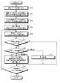
図12は、層別補正処理の処理ブロックと層間補正処理の処理ブロックの処理の順番の一例を示す図である。図12に示すように、本実施の形態では、層別補正処理の処理ブロックB1を全ての層(1層、2層、・・・k層、k+1層、・・・、n層)に対して終えてから、層間補正処理の処理ブロックB2を実施する。(Processing flow)
FIG. 12 is a diagram illustrating an example of the processing order of the processing block for the layer-specific correction processing and the processing block for the interlayer correction processing. As shown in FIG. 12, in the present embodiment, the processing block B1 of the layer-specific correction processing is applied to all layers (1 layer, 2 layers,... K layer, k + 1 layer,..., N layer). Then, processing block B2 for interlayer correction processing is performed.
次に、情報処理装置1の造形データ出力処理部(造形データ読込部15、ノズル情報管理部16、材料プロファイル管理部17、層別補正部18、及び層間補正部19)が行う処理ブロックB1と処理ブロックB2の処理フローの一例を示す。CAM処理部14が行う造形データの生成フローについては、従来の処理であるため、ここでの図示及び説明を省略する。 Next, the processing block B1 performed by the modeling data output processing unit (the modeling
図13は、層別補正処理の処理ブロックB1の処理フローの一例を示す図である。なお、造形データは、CAM処理部14が生成したものに限らず、外部のCAM装置が生成したものであっても良い。この場合には、外部のCAM装置が生成した造形データを情報処理装置1の指定パス(第2のパス)にコピーしておく。 FIG. 13 is a diagram illustrating an example of a processing flow of the processing block B1 of the layered correction processing. The modeling data is not limited to the data generated by the
先ず、造形データ読込部15は、第2のパスから造形データを読み込む(S10)。続いて、造形データ読込部15は、読み込んだ造形データ(補正対象データ)から制御対象ノズルの識別情報(本例ではノズル番号)と造形データP1に対応する材料種別(第1の材料種別)の識別情報とを読み取り、読み取ったノズル番号と第1の材料種別の識別情報とをノズル情報管理部16に出力する(S11)。 First, the modeling
ノズル情報管理部16は、造形データ読込部15からのノズル番号の入力により、ノズル情報D1(図5参照)から当該ノズル番号に対応する材料種別(第2の材料種別)の識別情報を読み取り、第1の材料種別の識別情報と、第2の材料種別の識別情報とを、材料プロファイル管理部17に出力する(S12)。 The nozzle
材料プロファイル管理部17は、ノズル情報管理部16からの第1と第2の材料種別の識別情報の入力により、材料プロファイルD2(図6参照)から、第1の材料種別の材料プロファイル(第1の材料プロファイル)と、第2の材料種別の材料プロファイル(第2の材料プロファイル)とを読み取り、読み取った各材料プロファイルを層別補正部18と層間補正部19とに出力する(S13)。 The material
層別補正部18は、材料プロファイル管理部17からの材料プロファイルの入力があると、当該補正対象データからパラメータを1つ読み取り(S14)、当該パラメータが材料に依存するものであるかを判定する(S15)。 When the material profile is input from the material
当該パラメータが材料に依存するものである場合(ステップS15:Yes)、層別補正部18は、当該パラメータの種別からパラメータ値の置き換えが可能であるかを判定する(S16)。例えば、層別補正部18は、当該パラメータが温度パラメータS(図9参照)である場合、パラメータ値の置き換えが可能であると判定する。一方、当該パラメータが、押し出しパラメータE(図9参照)である場合、パラメータ値の置き換えは不可能であると判定する。後者の場合、層別補正部18はパラメータ値の算出を行うことになる。 If the parameter depends on the material (step S15: Yes), the
層別補正部18は、パラメータ値の置き換えが可能であると判定した場合(ステップS16:Yes)、当該パラメータ値を、第2の材料プロファイルの設定値により置き換える(S17)。 When determining that the parameter value can be replaced (step S16: Yes), the layer-specific correcting
層別補正部18は、パラメータ値の置き換えが不可能であると判定した場合は(ステップS16:No)、当該パラメータ値を、後述する算出処理の結果により置き換える(S18)。この算出処理において、層別補正部18は、第1の材料プロファイルの設定値と、第2の材料プロファイルの設定値と、当該パラメータに設定されているパラメータ値とから、置き換える値を算出する。算出処理の具体例は後述する。 If it is determined that the parameter value cannot be replaced (step S16: No), the
ステップS17とステップS18の処理後、層別補正部18は、当該補正対象データにおいて未処理のパラメータが残っているかを判定する(S19)。また、層別補正部18は、ステップS15でNo判定であった場合もステップS19の判定を行う。 After the processing of step S17 and step S18, the
当該補正対象データにおいて未処理のパラメータが残っている場合(ステップS19:Yes)、残りのパラメータについてステップS14から処理を繰り返す。 If unprocessed parameters remain in the correction target data (step S19: Yes), the processing is repeated from step S14 for the remaining parameters.
当該補正対象データにおいて未処理のパラメータが残っていない場合は(ステップS19:No)、本処理を終了する。 When there is no unprocessed parameter remaining in the correction target data (step S19: No), this process ends.
図14は、ステップS20に示す算出処理の処理フローの一例を示す図である。ここでは、一例として、ステップS14において層別補正部18が造形データP1(図9参照)の5行目に示す押し出し量パラメータEを読み取った場合の処理について示す。 FIG. 14 is a diagram illustrating an example of a processing flow of the calculation process illustrated in step S20. Here, as an example, a process when the layer-by-
先ず、層別補正部18は、当該補正対象データから、ステップS14で読み取った押し出し量パラメータEのパラメータ値(この場合「5」)を読み取る(S21)。 First, the layer-
続いて、層別補正部18は、第1の材料プロファイルから、フィラメント径の設定値を読み取る(S22)。 Subsequently, the
続いて、層別補正部18は、第2の材料プロファイルから、フィラメント径の設定値を読み取る(S23)。 Subsequently, the layer-
続いて、層別補正部18は、第1の材料プロファイルのフィラメント径の設定値(第1の設定値)と、第2の材料プロファイルのフィラメント径の設定値(第2の設定値)と、当該補正対象データから読み取った押し出し量パラメータEのパラメータ値(「5」)とから、置換用の値を算出する(S24)。 Subsequently, the layer-
例えば、第1の材料プロファイルが、材料名「PLA」のデータd21(図6参照)で、第2の材料プロファイルが、材料名「ABS」のデータd20(図6参照)であったとする。この場合、層別補正部18はデータd21からフィラメント径「2mm」を第1の設定値として読み取り、データd20からフィラメント径「1mm」を第2の設定値として読み取る。押し出し量パラメータEのパラメータ値(フィラメントの押し出し長「5」)は、フィラメント径が第1の設定値(「2mm」)の場合の値である。フィラメントの材料種別の変更後は、フィラメント径が第2の設定値(「1mm」)と細く、断面積が1/4倍になる。従って、フィラメントの押し出し量(体積)を同じにするために、押し出し量パラメータEのパラメータ値「5」から4倍の「20」を算出し、「20」を置換用の値とする。 For example, it is assumed that the first material profile is data d21 (see FIG. 6) of the material name “PLA” and the second material profile is data d20 (see FIG. 6) of the material name “ABS”. In this case, the
そして、層別補正部18は、当該パラメータ値を、置換用の値により置き換える(S25)。 Then, the
図15は、造形補正データの一例を示す図である。図15には、造形材料(フィラメント)をPLA樹脂とした造形データP1(図9参照)を基に、ABS樹脂の造形データを補正した場合の、元の造形データと補正後の造形データ(造形補正データ)の比較図を示している。 FIG. 15 is a diagram illustrating an example of modeling correction data. FIG. 15 shows the original modeling data and the corrected modeling data (modeling) when the modeling data of the ABS resin is corrected based on the modeling data P1 (see FIG. 9) using the modeling material (filament) as PLA resin. A comparison diagram of correction data) is shown.
図15に示すように、造形補正データでは、パラメータ値の置き換えが可能であるパラメータについては、PLAの設定値からABSの設定値に置き換えが行われている。また、パラメータ値の置き換えが可能でないパラメータについては、上述した算出処理により算出した置換用の値により、ABSに対応する設定値に置き換えが行われている。 As shown in FIG. 15, in the modeling correction data, parameters that can be replaced with parameter values are replaced from PLA setting values to ABS setting values. In addition, parameters that cannot be replaced with parameter values are replaced with setting values corresponding to the ABS by the replacement values calculated by the above-described calculation processing.
図16は、層間補正処理の処理ブロックB2の処理フローの一例を示す図である。先ず、層間補正部19は、変数kにデフォルト値「1」を設定する(S30)。 FIG. 16 is a diagram illustrating an example of a processing flow of the processing block B2 of the interlayer correction processing. First, the
続いて、層間補正部19は、k層とk+1層の造形補正データを選択する(S31)。ここで、k+1層はk層よりも1つ上の層であるものとする。 Subsequently, the
続いて、層間補正部19は、k層の造形所要時間が一層最小時間未満であるかを判定する(S32)。具体的に、層間補正部19は、k層の造形補正データから造形所要時間を算出し、その時間が、第2の材料プロファイルの一層最小時間の項目k16(図6参照)に設定されている設定時間未満であるかを判定する。 Subsequently, the
k層の造形所要時間が一層最小時間未満である場合(ステップS32:Yes)、層間補正部19は、k+1層の造形補正データに、k+1層の造形開始を設定時間遅らせるための待機コマンド(「待機情報」の一例)を埋め込む(S33)。待機コマンドの設定時間は、k層の造形所要時間と設定時間との合計時間が一層最小時間を上回るようなものに設定にする。 When the modeling required time of the k layer is further less than the minimum time (step S32: Yes), the
層間補正部19は、k層の造形所要時間が一層最小時間以上である場合は(ステップS32:No)、ステップS33の処理をとばし、k層の造形補正データに設定されているノズル温度パラメータのパラメータ値がk+1層のものよりも大きいかを判定する(S34)。 If the time required for modeling the k layer is more than the minimum time (step S32: No), the
k層のノズル温度パラメータのパラメータ値がk+1層のものよりも大きい場合(ステップS34:Yes)、層間補正部19は、k+1層のノズル温度パラメータのパラメータ値をk層のノズル温度パラメータのパラメータ値に近づくように補正する(S35)。つまり、k+1層の造形時のノズル温度を上昇させる。 When the parameter value of the nozzle temperature parameter of the k layer is larger than that of the k + 1 layer (step S34: Yes), the
層間補正部19は、k層のノズル温度パラメータのパラメータ値がk+1層のもの以下である場合は(ステップS34:No)、ステップS35の処理をとばし、変数kが層数の上限値を超えたかを判定する(S36)。 When the parameter value of the nozzle temperature parameter of the k layer is equal to or less than that of the k + 1 layer (step S34: No), the
変数kが層数の上限値を超えていない場合(ステップS36:No)、層間補正部19は、変数kを1インクリメントし(S37)、ステップS31からの処理を行う。つまり、層間補正部19は、1つ上の層の造形補正データを対象に層間補正処理を行う。 When the variable k does not exceed the upper limit value of the number of layers (step S36: No), the
変数kが層数の上限値を超えた場合は(ステップS36:Yes)、全ての層に対して層間補正が終わっているため、層間補正部19は、各層の当該層間補正処理を終了する。 If the variable k exceeds the upper limit value of the number of layers (step S36: Yes), since the interlayer correction has been completed for all layers, the
本実施の形態において説明した、CAM処理手段1−1(図1参照)による造形データの生成処理や、補正処理手段1−2(図1参照)による造形データの補正処理は、処理の一部又は全てを造形装置2で行うようにしても良い。 The modeling data generation process by the CAM processing unit 1-1 (see FIG. 1) and the modeling data correction process by the correction processing unit 1-2 (see FIG. 1) described in the present embodiment are part of the processing. Alternatively, all may be performed by the
(第2の実施の形態)
図17は、第2の実施の形態に係る「造形システム」のシステム構成の一例を示す図である。図17に示す造形システムX2は、図1に示す第1の実施形態に係る造形システムX1と同様、情報処理装置1と造形装置2とを含むようにして構成される。CAM処理手段1−1と補正処理手段1−2については、CAM処理手段1−1を情報処理装置1に配置し、補正処理手段1−2を造形装置2に配置している。(Second Embodiment)
FIG. 17 is a diagram illustrating an example of a system configuration of a “modeling system” according to the second embodiment. The modeling system X2 illustrated in FIG. 17 is configured to include the
第2の実施の形態では、造形装置2のROM251(図4参照)に、造形データの出力処理を行うプログラムやデータを記憶させる。データには、「ノズル情報D1(図5参照)」や、「材料プロファイル(情報)D2(図6参照)」などを含める。 In 2nd Embodiment, the program and data which perform the output process of modeling data are memorize | stored in ROM251 (refer FIG. 4) of the
(機能構成)
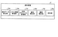
図18は、造形装置2の機能構成の一例を示す図である。図18に示すように、造形データ出力処理部として、造形データ読込部15aと、ノズル情報管理部16aと、材料プロファイル管理部17aと、層別補正部18aと、層間補正部19aと、造形部20aとを有する。各部は、それぞれ、図7に示す造形データ読込部15と、ノズル情報管理部16と、材料プロファイル管理部17と、層別補正部18と、層間補正部19と、造形部20aに対応する機能を有する。なお、情報処理装置1と造形装置2の各機能部の連携動作については、図11に示す説明の繰り返しになるため、ここでの説明は省略する。(Functional configuration)
FIG. 18 is a diagram illustrating an example of a functional configuration of the
(処理フロー)
第1の実施の形態では、層別補正処理の処理ブロックB1(図12参照)を全ての層について行い、その後、層間補正処理の処理ブロックB2(図12参照)を行う例を示した。第2の実施の形態では、造形装置2において、層別補正処理の処理ブロックB1と層間補正処理の処理ブロックB2の順番を適宜変形することができる。(Processing flow)
In the first embodiment, the example in which the processing block B1 (see FIG. 12) of the layer-by-layer correction processing is performed for all layers, and then the processing block B2 (see FIG. 12) of the interlayer correction processing is performed. In the second embodiment, in the
図19は、層別補正処理の処理ブロックB1と層間補正処理の処理ブロックB2の順番の一変形例を示す図である。図19に示すように、先ず1層目(最下層)の層別補正処理行い、層別補正処理後の1層目の造形データを造形部20aに出力する。 FIG. 19 is a diagram illustrating a modification of the order of the processing block B1 for layer-by-layer correction processing and the processing block B2 for interlayer correction processing. As shown in FIG. 19, first, the first layer (lowermost layer) layer-by-layer correction process is performed, and the first layer modeling data after the layer-by-layer correction process is output to the
次に、2層目(1層目の上の層)の層別補正処理を行い、これに続けて、1層目の層別補正処理後の造形データを用いて2層目の層間補正処理を行う。それから、層間補正処理後の2層目の造形データを造形部20aに出力する。その後も同様に、k層目の層別補正処理を行い、これに続けて、k−1層目の層別補正処理後の造形データを用いてk層目の層間補正処理を行う。それから、層間補正処理後のk層目の造形データを造形部20aに出力する。そして、n層目(最上位層)の層別補正処理を行い、これに続けて、n−1層目の層別補正処理後の造形データを用いてn層目の層間補正処理を行う。そして、層間補正処理後のn層目の造形データを造形部20aに出力する。 Next, a layer-by-layer correction process for the second layer (the layer above the first layer) is performed, followed by a layer-by-layer correction process using the modeling data after the layer-by-layer correction process for the first layer. I do. Then, the modeling data of the second layer after the interlayer correction process is output to the
このように、造形装置2では、層別補正処理の処理ブロックB1と層間補正処理の処理ブロックB2の順番を適宜変形することができる。この変形により、造形部20aは、全ての層の造形データをバッファしておく必要がないため、メモリ領域が少ない場合でも造形データを補正することが可能になる。また、層毎に層間補正処理を行うため、造形部20aに順次造形データを出力することが可能になり、造形を直ぐに開始することができるという効果を奏する。 Thus, in the
各実施の形態では、熱溶解積層方式の造形装置への適用例を示したが、この方式に限定するものではない。例えば、光造形方式、粉末焼成積層方式、インクジェット方式などに適用しても良い。 In each embodiment, although the example of application to the modeling apparatus of a hot melt lamination system was shown, it is not limited to this system. For example, the present invention may be applied to an optical modeling method, a powder firing lamination method, an ink jet method, and the like.
また、造形材料体は、モデル材に限らず、サポート材としても良い。 Further, the modeling material body is not limited to the model material, and may be a support material.
以上のように、各実施の形態では、1つの造形データから他の造形材料に適合する造形データを生成することが可能になる。 As described above, in each embodiment, it is possible to generate modeling data suitable for another modeling material from one modeling data.
各実施の形態の情報処理装置で実行されるプログラムは、インストール可能な形式又は実行可能な形式のファイルでCD−ROM、フレキシブルディスク(FD)、CD−R、DVD(Digital Versatile Disk)等のコンピュータで読み取り可能な記録媒体に記録されて提供される。 A program executed in the information processing apparatus according to each embodiment is a file in an installable format or an executable format, and is a computer such as a CD-ROM, a flexible disk (FD), a CD-R, or a DVD (Digital Versatile Disk). Recorded on a readable recording medium.
また、各実施の形態の情報処理装置で実行されるプログラムを、インターネット等のネットワークに接続されたコンピュータ上に格納し、ネットワーク経由でダウンロードさせることにより提供するように構成しても良い。また、各実施の形態の情報処理装置で実行されるプログラムをインターネット等のネットワーク経由で提供または配布するように構成しても良い。 Further, the program executed by the information processing apparatus according to each embodiment may be provided by being stored on a computer connected to a network such as the Internet and downloaded via the network. The program executed by the information processing apparatus according to each embodiment may be provided or distributed via a network such as the Internet.
また、各実施の形態のプログラムを、ROM等に予め組み込んで提供するように構成してもよい。 Further, the program of each embodiment may be configured to be provided by being incorporated in advance in a ROM or the like.
1 情報処理装置
1−1 CAM処理手段
1−2 補正処理手段
2 造形装置
20 造形処理手段
X1 造形システムDESCRIPTION OF
Claims (13)
Translated fromJapanese第2の造形材料体についての造形材料体情報を記憶する記憶手段と、
前記読込手段により読み込まれた前記命令情報に含まれる、前記第1の造形材料体についての第1のパラメータ値を、前記記憶手段により記憶されている前記造形材料体情報に基づいて補正する補正手段と、
を有する情報処理装置。Reading means for reading command information for causing the modeling apparatus to execute a modeling procedure for the first modeling material body;
Storage means for storing modeling material body information about the second modeling material body;
Correction means for correcting the first parameter value for the first modeling material body included in the command information read by the reading means based on the modeling material body information stored in the storage means When,
An information processing apparatus.
前記補正手段は、前記読込手段により読み込まれた前記命令情報に含まれる前記第1のパラメータ値を、前記記憶手段により記憶されている前記第1の造形材料体についての造形材料体情報と前記第2の造形材料体についての造形材料体情報とに基づく算出結果の値により補正する、
請求項1に記載の情報処理装置。The storage means further stores modeling material body information about the first modeling material body,
The correction means includes the first parameter value included in the command information read by the reading means, the modeling material body information on the first modeling material body stored in the storage means, and the first parameter value. Correction based on the value of the calculation result based on the modeling material body information on the modeling material body of 2,
The information processing apparatus according to claim 1.
前記第1の造形材料体についての前記造形材料体情報は、前記第1の造形材料体の外形情報を示す第1の外形形状情報を有し、
前記第2の造形材料体についての前記造形材料体情報は、前記第2の造形材料体の外形情報を示す第2の外形形状情報を有し、
前記補正手段は、前記読込手段により読み込まれた前記命令情報に含まれる、前記第1のパラメータ値である第1の造形材料体の吐出量を、該吐出量と、前記記憶手段により記憶されている前記第1の外形形状情報と、前記第2の外形形状情報とに基づいて算出した値により補正する、
請求項2に記載の情報処理装置。The modeling material body is a filament,
The modeling material body information about the first modeling material body has first outer shape information indicating the outer shape information of the first modeling material body,
The modeling material body information about the second modeling material body has second outer shape information indicating the outer shape information of the second modeling material body,
The correction unit stores the discharge amount of the first modeling material body, which is the first parameter value, included in the command information read by the reading unit, and the discharge amount and the storage unit. The first outer shape information and the second outer shape information are corrected by a value calculated based on the first outer shape information and the second outer shape information.
The information processing apparatus according to claim 2.
造形材料体を吐出するノズルの識別情報と該造形材料体の識別情報との対応関係を示す対応情報と、
前記第2の造形材料体についての造形材料体情報としての、前記対応情報に含まれる造形材料体についての造形材料体情報と、
を記憶し、
前記補正手段は、前記第1の造形材料体についての前記命令情報に含まれる前記第1のパラメータ値を、前記対応情報において前記造形装置のノズルの識別情報と対応付けられている造形材料体の識別情報に対応する造形材料体情報に基づいて補正する、
請求項1乃至3の内の何れか一項に記載の情報処理装置。The storage means
Correspondence information indicating the correspondence between the identification information of the nozzle that discharges the modeling material body and the identification information of the modeling material body,
As modeling material body information about the second modeling material body, modeling material body information about the modeling material body included in the correspondence information; and
Remember
The correction unit is configured to associate the first parameter value included in the instruction information about the first modeling material body with the identification information of the nozzle of the modeling apparatus in the correspondence information. Correction based on modeling material body information corresponding to the identification information,
The information processing apparatus according to any one of claims 1 to 3.
前記補正手段は、前記第1の造形材料体についての前記命令情報に含まれる前記第1のパラメータ値を、前記記憶手段により記憶されている前記第2のパラメータ値による置換により補正する、
請求項1乃至4の内の何れか一項に記載の情報処理装置。The modeling material body information has a second parameter value for the second modeling material body corresponding to the first parameter value for the first modeling material body,
The correction means corrects the first parameter value included in the command information about the first modeling material body by replacement with the second parameter value stored in the storage means,
The information processing apparatus according to any one of claims 1 to 4.
請求項5に記載の情報処理装置。The command information has a temperature at which the first modeling material body is melted as the first parameter value.
The information processing apparatus according to claim 5.
前記命令情報において下の層の命令情報に基づいて上の層の命令情報を補正する層間補正手段を有する、
請求項1乃至6の内の何れか一項に記載の情報処理装置。Furthermore,
Interlayer correction means for correcting the instruction information of the upper layer based on the instruction information of the lower layer in the instruction information,
The information processing apparatus according to any one of claims 1 to 6.
請求項7に記載の情報処理装置。The interlayer correction means includes waiting information until the start of modeling in the command information of the upper layer based on the modeling required time of the lower layer,
The information processing apparatus according to claim 7.
請求項7または8に記載の情報処理装置。The interlayer correction means corrects the temperature related to the upper layer modeling material body based on the temperature related to the lower layer modeling material body,
The information processing apparatus according to claim 7 or 8.
第2の造形材料体についての造形材料体情報を記憶する記憶手段と、
前記読込手段により読み込まれた前記命令情報に含まれる、前記第1の造形材料体についての第1のパラメータ値を、前記記憶手段により記憶されている前記造形材料体情報に基づいて補正する補正手段と、
前記補正手段により補正された命令情報に従って造形を行う造形手段と、
を有する造形装置。Reading means for reading command information for executing a modeling procedure for the first modeling material body;
Storage means for storing modeling material body information about the second modeling material body;
Correction means for correcting the first parameter value for the first modeling material body included in the command information read by the reading means based on the modeling material body information stored in the storage means When,
Modeling means for modeling according to the command information corrected by the correction means;
A modeling apparatus having
第1の造形材料体についての造形手順を実行する命令情報を読み込む読込手段と、
第2の造形材料体についての造形材料体情報を記憶する記憶手段と、
前記読込手段により読み込まれた前記命令情報に含まれる、前記第1の造形材料体についての第1のパラメータ値を、前記記憶手段により記憶されている前記造形材料体情報に基づいて補正する補正手段と、
を有する造形システム。A modeling system having an information processing device and a modeling device,
Reading means for reading command information for executing a modeling procedure for the first modeling material body;
Storage means for storing modeling material body information about the second modeling material body;
Correction means for correcting the first parameter value for the first modeling material body included in the command information read by the reading means based on the modeling material body information stored in the storage means When,
A modeling system having
第2の造形材料体についての造形材料体情報を読み取る工程と、
前記命令情報に含まれる、前記第1の造形材料体についての第1のパラメータ値を前記造形材料体情報に基づいて補正する工程と、
を含む方法。A step of reading instruction information for executing a modeling procedure for the first modeling material body;
Reading the modeling material body information about the second modeling material body;
Correcting the first parameter value for the first modeling material body included in the command information based on the modeling material body information;
Including methods.
第1の造形材料体についての造形手順を実行する命令情報を読み込む読込手段と、
前記記憶部から前記造形材料体情報を読み取る読取手段と、
前記読込手段により読み込まれた前記命令情報に含まれる、前記第1の造形材料体についての第1のパラメータ値を、前記読取手段により読み取られた前記造形材料体情報に基づいて補正する補正手段と、
して機能させるためのプログラム。A computer of an information processing apparatus having a storage unit that stores modeling material body information about the second modeling material body,
Reading means for reading command information for executing a modeling procedure for the first modeling material body;
Reading means for reading the modeling material body information from the storage unit;
Correction means for correcting the first parameter value for the first modeling material body included in the command information read by the reading means based on the modeling material body information read by the reading means; ,
Program to make it function.
Priority Applications (6)
| Application Number | Priority Date | Filing Date | Title |
|---|---|---|---|
| JP2016235385AJP2018089859A (en) | 2016-12-02 | 2016-12-02 | Information processing apparatus, modeling apparatus, modeling system, method, and program |
| EP17811732.1AEP3548285A1 (en) | 2016-12-02 | 2017-11-20 | Information processing device, modeling device, modeling system, method and computer-readable recording medium |
| NZ753800ANZ753800B2 (en) | 2016-12-02 | 2017-11-20 | Information processing device, modeling device, modeling system, method and computer-readable recording medium |
| PCT/JP2017/041724WO2018101111A1 (en) | 2016-12-02 | 2017-11-20 | Information processing device, modeling device, modeling system, method and computer-readable recording medium |
| AU2017368439AAU2017368439B2 (en) | 2016-12-02 | 2017-11-20 | Information processing device, modeling device, modeling system, method and computer-readable recording medium |
| US16/418,196US20190315066A1 (en) | 2016-12-02 | 2019-05-21 | Information processing device, modeling device, modeling system, method and computer-readable recording medium |
Applications Claiming Priority (1)
| Application Number | Priority Date | Filing Date | Title |
|---|---|---|---|
| JP2016235385AJP2018089859A (en) | 2016-12-02 | 2016-12-02 | Information processing apparatus, modeling apparatus, modeling system, method, and program |
Publications (1)
| Publication Number | Publication Date |
|---|---|
| JP2018089859Atrue JP2018089859A (en) | 2018-06-14 |
Family
ID=60629772
Family Applications (1)
| Application Number | Title | Priority Date | Filing Date |
|---|---|---|---|
| JP2016235385APendingJP2018089859A (en) | 2016-12-02 | 2016-12-02 | Information processing apparatus, modeling apparatus, modeling system, method, and program |
Country Status (5)
| Country | Link |
|---|---|
| US (1) | US20190315066A1 (en) |
| EP (1) | EP3548285A1 (en) |
| JP (1) | JP2018089859A (en) |
| AU (1) | AU2017368439B2 (en) |
| WO (1) | WO2018101111A1 (en) |
Cited By (3)
| Publication number | Priority date | Publication date | Assignee | Title |
|---|---|---|---|---|
| JP2019098736A (en)* | 2017-12-06 | 2019-06-24 | 三緯國際立體列印科技股▲フン▼有限公司 | Slice method of color 3d object, renewal method of slice data, and printing system using slice data |
| JP2019155856A (en)* | 2018-03-16 | 2019-09-19 | 株式会社リコー | Three-dimensional modeling system, three-dimensional modeling method, program thereof, and computer-readable memory medium memorizing same |
| JP2023097689A (en)* | 2021-12-28 | 2023-07-10 | セイコーエプソン株式会社 | 3D printer |
Families Citing this family (2)
| Publication number | Priority date | Publication date | Assignee | Title |
|---|---|---|---|---|
| JP6801254B2 (en)* | 2015-08-20 | 2020-12-16 | 株式会社リコー | Image forming device, stereoscopic image modeling method and program |
| US12322600B2 (en)* | 2019-12-27 | 2025-06-03 | SCREEN Holdings Co., Ltd. | Substrate treatment apparatus, substrate treatment method, substrate treatment system, and learning data generation method |
Citations (3)
| Publication number | Priority date | Publication date | Assignee | Title |
|---|---|---|---|---|
| JP2005523391A (en)* | 2002-04-17 | 2005-08-04 | ストラッタシス, インコーポレイテッド | High precision modeling filament |
| JP2009500194A (en)* | 2005-07-01 | 2009-01-08 | ストラタシス・インコーポレイテッド | Rapid prototyping system using controlled raw materials |
| JP2016107462A (en)* | 2014-12-04 | 2016-06-20 | ローランドディー.ジー.株式会社 | Three-dimensional molding apparatus |
Family Cites Families (5)
| Publication number | Priority date | Publication date | Assignee | Title |
|---|---|---|---|---|
| US7572403B2 (en)* | 2003-09-04 | 2009-08-11 | Peihua Gu | Multisource and multimaterial freeform fabrication |
| US10046521B2 (en)* | 2014-01-16 | 2018-08-14 | Jabil Inc. | Remotely-accessible additive manufacturing systems and methods |
| US9841750B2 (en)* | 2014-05-13 | 2017-12-12 | Autodesk, Inc. | Dynamic real-time slice engine for 3D printing |
| JP2016132214A (en) | 2015-01-21 | 2016-07-25 | キヤノン株式会社 | Three-dimensional molding apparatus and three-dimensional molding method |
| US9895845B2 (en)* | 2015-02-16 | 2018-02-20 | Arevo Inc. | Method and a system to optimize printing parameters in additive manufacturing process |
- 2016
- 2016-12-02JPJP2016235385Apatent/JP2018089859A/enactivePending
- 2017
- 2017-11-20WOPCT/JP2017/041724patent/WO2018101111A1/ennot_activeCeased
- 2017-11-20AUAU2017368439Apatent/AU2017368439B2/ennot_activeCeased
- 2017-11-20EPEP17811732.1Apatent/EP3548285A1/ennot_activeWithdrawn
- 2019
- 2019-05-21USUS16/418,196patent/US20190315066A1/ennot_activeAbandoned
Patent Citations (3)
| Publication number | Priority date | Publication date | Assignee | Title |
|---|---|---|---|---|
| JP2005523391A (en)* | 2002-04-17 | 2005-08-04 | ストラッタシス, インコーポレイテッド | High precision modeling filament |
| JP2009500194A (en)* | 2005-07-01 | 2009-01-08 | ストラタシス・インコーポレイテッド | Rapid prototyping system using controlled raw materials |
| JP2016107462A (en)* | 2014-12-04 | 2016-06-20 | ローランドディー.ジー.株式会社 | Three-dimensional molding apparatus |
Cited By (4)
| Publication number | Priority date | Publication date | Assignee | Title |
|---|---|---|---|---|
| JP2019098736A (en)* | 2017-12-06 | 2019-06-24 | 三緯國際立體列印科技股▲フン▼有限公司 | Slice method of color 3d object, renewal method of slice data, and printing system using slice data |
| JP2019155856A (en)* | 2018-03-16 | 2019-09-19 | 株式会社リコー | Three-dimensional modeling system, three-dimensional modeling method, program thereof, and computer-readable memory medium memorizing same |
| JP2023097689A (en)* | 2021-12-28 | 2023-07-10 | セイコーエプソン株式会社 | 3D printer |
| US12358233B2 (en) | 2021-12-28 | 2025-07-15 | Seiko Epson Corporation | Three-dimensional shaping device |
Also Published As
| Publication number | Publication date |
|---|---|
| AU2017368439A1 (en) | 2019-06-06 |
| US20190315066A1 (en) | 2019-10-17 |
| NZ753800A (en) | 2020-10-30 |
| WO2018101111A1 (en) | 2018-06-07 |
| EP3548285A1 (en) | 2019-10-09 |
| AU2017368439B2 (en) | 2021-04-08 |
Similar Documents
| Publication | Publication Date | Title |
|---|---|---|
| JP2018089859A (en) | Information processing apparatus, modeling apparatus, modeling system, method, and program | |
| US10328686B2 (en) | Determining print-time for generation of 3D objects based on 3D printing parameters | |
| CN108292325B (en) | System and method for optimizing tool paths based on thermal/structural simulation of components | |
| EP3774299B1 (en) | Generating adapted control instructions for a 3d printing process | |
| TWI594099B (en) | Three-dimensional object generation technology | |
| CN110168546B (en) | System and method for adaptive domain reduction for thermo-structural simulation of additive manufacturing processes | |
| KR20220093171A (en) | Systems, methods and media for manufacturing processes | |
| US11390031B2 (en) | Additive manufacturing system and method for post-processing | |
| TWI765403B (en) | Systems and methods for manufacturing processes, and three-dimensional (3d) printing stsyem | |
| TWI556946B (en) | Three dimensional printing apparatus and method for controlling printing head thereof | |
| JP2019177494A (en) | Control system, molding system, and program | |
| US10252467B2 (en) | Control method of printing temperature and device thereof | |
| JPWO2018123858A1 (en) | Thermal deformation calculation device, three-dimensional stacking system, three-dimensional stacking method, and program | |
| CN105683850A (en) | Program creation device, program creation method, and program | |
| CN108995201A (en) | Warping-proof printing method of 3D printer | |
| JP6386511B2 (en) | Tool path generation device, tool path generation method, and tool path generation program | |
| JP6564094B2 (en) | Color 3D object slicing method, slice data updating method, and printing system using slice data | |
| US20170165918A1 (en) | Information processing apparatus for additive manufacturing system, information processing method for additive manufacturing system, and storage medium | |
| CN103489054A (en) | Manufacturing management apparatus and manufacturing management system of electronic device | |
| JP2017109320A (en) | Information processing device, 3d printer system, information processing method, and computer program | |
| CN119840175A (en) | Method and device for 3D printer, 3D printer and storage medium | |
| WO2023193797A1 (en) | Method and apparatus for 3d printing, and device, storage medium, and program product | |
| JP6296809B2 (en) | 3D printer support program, medium storing 3D printer support program, and 3D printer support apparatus storing 3D printer support program. | |
| KR101958998B1 (en) | Method for calculating of 3D printer preview based on measured material deformation | |
| JP7277272B2 (en) | Machine learning device, prediction device, and control device |
Legal Events
| Date | Code | Title | Description |
|---|---|---|---|
| A621 | Written request for application examination | Free format text:JAPANESE INTERMEDIATE CODE: A621 Effective date:20191105 | |
| A131 | Notification of reasons for refusal | Free format text:JAPANESE INTERMEDIATE CODE: A131 Effective date:20201215 | |
| A02 | Decision of refusal | Free format text:JAPANESE INTERMEDIATE CODE: A02 Effective date:20210713 |