JP2018085552A - Projector system - Google Patents
Projector systemDownload PDFInfo
- Publication number
- JP2018085552A JP2018085552AJP2016225729AJP2016225729AJP2018085552AJP 2018085552 AJP2018085552 AJP 2018085552AJP 2016225729 AJP2016225729 AJP 2016225729AJP 2016225729 AJP2016225729 AJP 2016225729AJP 2018085552 AJP2018085552 AJP 2018085552A
- Authority
- JP
- Japan
- Prior art keywords
- projection
- image
- projector
- indicator
- imaging unit
- Prior art date
- Legal status (The legal status is an assumption and is not a legal conclusion. Google has not performed a legal analysis and makes no representation as to the accuracy of the status listed.)
- Withdrawn
Links
Images


Classifications
- G—PHYSICS
- G06—COMPUTING OR CALCULATING; COUNTING
- G06F—ELECTRIC DIGITAL DATA PROCESSING
- G06F3/00—Input arrangements for transferring data to be processed into a form capable of being handled by the computer; Output arrangements for transferring data from processing unit to output unit, e.g. interface arrangements
- G06F3/01—Input arrangements or combined input and output arrangements for interaction between user and computer
- G06F3/03—Arrangements for converting the position or the displacement of a member into a coded form
- G06F3/041—Digitisers, e.g. for touch screens or touch pads, characterised by the transducing means
- G06F3/042—Digitisers, e.g. for touch screens or touch pads, characterised by the transducing means by opto-electronic means
- G06F3/0425—Digitisers, e.g. for touch screens or touch pads, characterised by the transducing means by opto-electronic means using a single imaging device like a video camera for tracking the absolute position of a single or a plurality of objects with respect to an imaged reference surface, e.g. video camera imaging a display or a projection screen, a table or a wall surface, on which a computer generated image is displayed or projected
- G—PHYSICS
- G03—PHOTOGRAPHY; CINEMATOGRAPHY; ANALOGOUS TECHNIQUES USING WAVES OTHER THAN OPTICAL WAVES; ELECTROGRAPHY; HOLOGRAPHY
- G03B—APPARATUS OR ARRANGEMENTS FOR TAKING PHOTOGRAPHS OR FOR PROJECTING OR VIEWING THEM; APPARATUS OR ARRANGEMENTS EMPLOYING ANALOGOUS TECHNIQUES USING WAVES OTHER THAN OPTICAL WAVES; ACCESSORIES THEREFOR
- G03B21/00—Projectors or projection-type viewers; Accessories therefor
- G03B21/14—Details
- G—PHYSICS
- G06—COMPUTING OR CALCULATING; COUNTING
- G06F—ELECTRIC DIGITAL DATA PROCESSING
- G06F3/00—Input arrangements for transferring data to be processed into a form capable of being handled by the computer; Output arrangements for transferring data from processing unit to output unit, e.g. interface arrangements
- G06F3/01—Input arrangements or combined input and output arrangements for interaction between user and computer
- G06F3/03—Arrangements for converting the position or the displacement of a member into a coded form
- G06F3/033—Pointing devices displaced or positioned by the user, e.g. mice, trackballs, pens or joysticks; Accessories therefor
- G06F3/0346—Pointing devices displaced or positioned by the user, e.g. mice, trackballs, pens or joysticks; Accessories therefor with detection of the device orientation or free movement in a 3D space, e.g. 3D mice, 6-DOF [six degrees of freedom] pointers using gyroscopes, accelerometers or tilt-sensors
- G—PHYSICS
- G06—COMPUTING OR CALCULATING; COUNTING
- G06F—ELECTRIC DIGITAL DATA PROCESSING
- G06F3/00—Input arrangements for transferring data to be processed into a form capable of being handled by the computer; Output arrangements for transferring data from processing unit to output unit, e.g. interface arrangements
- G06F3/01—Input arrangements or combined input and output arrangements for interaction between user and computer
- G06F3/03—Arrangements for converting the position or the displacement of a member into a coded form
- G06F3/041—Digitisers, e.g. for touch screens or touch pads, characterised by the transducing means
- G06F3/042—Digitisers, e.g. for touch screens or touch pads, characterised by the transducing means by opto-electronic means
- G—PHYSICS
- G06—COMPUTING OR CALCULATING; COUNTING
- G06T—IMAGE DATA PROCESSING OR GENERATION, IN GENERAL
- G06T7/00—Image analysis
- G06T7/70—Determining position or orientation of objects or cameras
- G—PHYSICS
- G06—COMPUTING OR CALCULATING; COUNTING
- G06V—IMAGE OR VIDEO RECOGNITION OR UNDERSTANDING
- G06V10/00—Arrangements for image or video recognition or understanding
- G06V10/10—Image acquisition
- G06V10/12—Details of acquisition arrangements; Constructional details thereof
- G06V10/14—Optical characteristics of the device performing the acquisition or on the illumination arrangements
- G06V10/145—Illumination specially adapted for pattern recognition, e.g. using gratings
- G—PHYSICS
- G06—COMPUTING OR CALCULATING; COUNTING
- G06V—IMAGE OR VIDEO RECOGNITION OR UNDERSTANDING
- G06V40/00—Recognition of biometric, human-related or animal-related patterns in image or video data
- G06V40/10—Human or animal bodies, e.g. vehicle occupants or pedestrians; Body parts, e.g. hands
- G06V40/107—Static hand or arm
- G06V40/113—Recognition of static hand signs
- H—ELECTRICITY
- H04—ELECTRIC COMMUNICATION TECHNIQUE
- H04N—PICTORIAL COMMUNICATION, e.g. TELEVISION
- H04N9/00—Details of colour television systems
- H04N9/12—Picture reproducers
- H04N9/31—Projection devices for colour picture display, e.g. using electronic spatial light modulators [ESLM]
- H—ELECTRICITY
- H04—ELECTRIC COMMUNICATION TECHNIQUE
- H04N—PICTORIAL COMMUNICATION, e.g. TELEVISION
- H04N9/00—Details of colour television systems
- H04N9/12—Picture reproducers
- H04N9/31—Projection devices for colour picture display, e.g. using electronic spatial light modulators [ESLM]
- H04N9/3179—Video signal processing therefor
- H—ELECTRICITY
- H04—ELECTRIC COMMUNICATION TECHNIQUE
- H04N—PICTORIAL COMMUNICATION, e.g. TELEVISION
- H04N9/00—Details of colour television systems
- H04N9/12—Picture reproducers
- H04N9/31—Projection devices for colour picture display, e.g. using electronic spatial light modulators [ESLM]
- H04N9/3191—Testing thereof
- H04N9/3194—Testing thereof including sensor feedback
- G—PHYSICS
- G06—COMPUTING OR CALCULATING; COUNTING
- G06T—IMAGE DATA PROCESSING OR GENERATION, IN GENERAL
- G06T2207/00—Indexing scheme for image analysis or image enhancement
- G06T2207/10—Image acquisition modality
- G06T2207/10004—Still image; Photographic image
- G06T2207/10012—Stereo images
- G—PHYSICS
- G06—COMPUTING OR CALCULATING; COUNTING
- G06T—IMAGE DATA PROCESSING OR GENERATION, IN GENERAL
- G06T2207/00—Indexing scheme for image analysis or image enhancement
- G06T2207/30—Subject of image; Context of image processing
- G06T2207/30196—Human being; Person
- H—ELECTRICITY
- H04—ELECTRIC COMMUNICATION TECHNIQUE
- H04N—PICTORIAL COMMUNICATION, e.g. TELEVISION
- H04N13/00—Stereoscopic video systems; Multi-view video systems; Details thereof
- H04N13/20—Image signal generators
- H04N13/204—Image signal generators using stereoscopic image cameras
- H04N13/239—Image signal generators using stereoscopic image cameras using two 2D image sensors having a relative position equal to or related to the interocular distance
Landscapes
- Engineering & Computer Science (AREA)
- Theoretical Computer Science (AREA)
- Physics & Mathematics (AREA)
- General Physics & Mathematics (AREA)
- General Engineering & Computer Science (AREA)
- Multimedia (AREA)
- Human Computer Interaction (AREA)
- Signal Processing (AREA)
- Computer Vision & Pattern Recognition (AREA)
- Artificial Intelligence (AREA)
- Projection Apparatus (AREA)
- Position Input By Displaying (AREA)
- Transforming Electric Information Into Light Information (AREA)
Abstract
Translated fromJapaneseDescription
Translated fromJapanese本発明は、投射画面上にある指等の指示体を検出してこれを投射画像の内容に反映させることで書き込みができるいわゆるインタラクティブなプロジェクターを実現するためのプロジェクターシステムに関する。 The present invention relates to a projector system for realizing a so-called interactive projector capable of writing by detecting an indicator such as a finger on a projection screen and reflecting it on the content of a projection image.
インタラクティブなプロジェクターとして、例えば投射画面(スクリーン)のほぼ全体に、赤外光の層を形成するように射出させる光出射装置を、プロジェクターの投射機構とは別個に設け、当該光出射装置からの赤外光が、指示体の先端(例えば、指先)で反射され、この反射光を検出することをもって指示体による指示操作を検出し、インタラクティブ機能を達成するものも知られている(例えば特許文献1参照。)。しかしながら、上記のような構成の場合、レーザーを照射する装置が必要で、さらに精密な位置合わせをする必要がある。また、検知可能な範囲が赤外光の層による2次元的な領域となる。 As an interactive projector, for example, a light emitting device that emits an infrared light layer on almost the entire projection screen (screen) is provided separately from the projection mechanism of the projector, and red light from the light emitting device is provided. It is also known that external light is reflected at the tip of the indicator (for example, a fingertip), and by detecting the reflected light, an instruction operation by the indicator is detected to achieve an interactive function (for example, Patent Document 1). reference.). However, in the case of the configuration as described above, an apparatus for irradiating a laser is necessary, and further precise alignment is necessary. Further, the detectable range is a two-dimensional area formed by the infrared light layer.
上記のような装置を使用しない方式として、指の形状を認識して指示位置を検出する方法がある。しかしながら、この場合、指の形状を認識するために、画像光の投射領域やその周辺領域までの広い範囲を検出する必要があり、例えば広画角の撮像装置等が必要になる。ただし、検出範囲が広がると、検出範囲のうち周辺側の領域は検出しにくくなる。例えば検出範囲を撮像しても、画像の周辺側では、検出されるべき対象箇所が歪められて小さくなってしまい、誤検出や不検出を生じてしまう可能性が高くなる。 As a method that does not use the device as described above, there is a method of detecting a pointing position by recognizing a finger shape. However, in this case, in order to recognize the shape of the finger, it is necessary to detect a wide range up to the image light projection area and its peripheral area. For example, an imaging device with a wide angle of view is required. However, when the detection range is widened, it is difficult to detect the peripheral region of the detection range. For example, even if the detection range is imaged, on the peripheral side of the image, the target portion to be detected is distorted and becomes small, and there is a high possibility that erroneous detection or non-detection occurs.
本発明は、インタラクティブなプロジェクターを実現するに際して、広い範囲での指示体の検出を可能とし、かつ、指示体の姿勢が変化しても、当該指示体の位置を確実に検出できるプロジェクターシステムを提供することを目的とする。 The present invention provides a projector system that enables detection of an indicator in a wide range when realizing an interactive projector, and can reliably detect the position of the indicator even if the orientation of the indicator changes. The purpose is to do.
上記目的を達成するため、本発明に係るプロジェクターシステムは、画像光を斜方投射するプロジェクター本体部と、プロジェクター本体部からの画像光の投影領域を含む立体的領域を撮像して立体的領域に存する指示体を検出可能にする立体射影方式の撮像部とを備える。 In order to achieve the above object, a projector system according to the present invention captures a three-dimensional area including a projector main body that projects image light obliquely and a projection area of the image light from the projector main body into a three-dimensional area. A stereoscopic projection imaging unit that enables detection of existing indicators.
上記プロジェクターシステムでは、撮像部を立体射影方式とすることにより画角を広げ、斜方投射された画像光による投影領域のみならず投影領域を含む立体的領域までを撮像可能とし、さらに、立体的領域に存する指示体を確実に捉えることができる。特に、立体射影方式を採用することで、撮像部の光学的設計の難易度を抑えつつ、被写体たる指示体の角度が変化しても当該指示体が画像上において歪んで小さくなることを回避し、当該指示体の位置を確実に検出できる。 In the projector system described above, the angle of view is widened by adopting a three-dimensional projection method for the imaging unit, so that not only a projection area by obliquely projected image light but also a three-dimensional area including the projection area can be imaged. The indicator in the area can be reliably captured. In particular, by adopting the three-dimensional projection method, the degree of difficulty in optical design of the imaging unit is suppressed, and even if the angle of the indicator that is the subject changes, the indicator is prevented from being distorted and reduced on the image. The position of the indicator can be reliably detected.
本発明の具体的な側面によれば、撮像部は、立体的領域をそれぞれ撮像する2以上のカメラを含む。この場合、指示体を立体的形状として捉えるための視差情報が取得可能となる。 According to a specific aspect of the present invention, the imaging unit includes two or more cameras that each capture a stereoscopic region. In this case, parallax information for capturing the indicator as a three-dimensional shape can be acquired.
本発明のさらに別の側面によれば、プロジェクター本体部において、スローレシオは、0.27以下である。すなわち、プロジェクターシステムは、いわゆる超短焦点近接投射を行うタイプとなっている。 According to still another aspect of the present invention, in the projector main body, the slow ratio is 0.27 or less. In other words, the projector system is of a type that performs so-called ultra short focus proximity projection.
本発明の別の側面によれば、プロジェクター本体部は、70インチ以上の投影領域を形成する。 According to another aspect of the present invention, the projector body forms a projection area of 70 inches or more.
本発明のさらに別の側面によれば、撮像部は、10°±5°の範囲内のあおり角で傾いている。例えばプロジェクターのスローレシオがより小さい場合には撮像部の画角を広くする必要があるが、あおり角を設けることであおり角を設けないものと比べて撮像部の広画角化を抑制できる。 According to still another aspect of the present invention, the imaging unit is inclined at a tilt angle within a range of 10 ° ± 5 °. For example, when the slow ratio of the projector is smaller, it is necessary to widen the angle of view of the imaging unit. However, it is possible to suppress the widening of the angle of view of the imaging unit as compared with the case where the tilt angle is provided and the angle is not provided.
本発明のさらに別の側面によれば、撮像部において、撮像範囲たる立体的領域は、投影領域から16cm以上手前までの領域を含む。この場合、指示体が例えば人の手指である場合において、人の手(あるいは指)の形状を特定して検出を行うのに十分な範囲を確保できる。 According to still another aspect of the present invention, in the imaging unit, the three-dimensional area that is the imaging range includes an area that is 16 cm or more from the projection area. In this case, when the indicator is, for example, a human finger, it is possible to secure a sufficient range for performing detection by specifying the shape of the human hand (or finger).
本発明のさらに別の側面によれば、撮像部で取得した画像光の情報に基づく画像投射位置と、撮像部により検出された指示体の位置とを特定し、特定した位置関係に基づく画像投影の制御を行うプロジェクター制御部をさらに備える。この場合、プロジェクター制御部によって、画像投射位置と指示体による指示位置とを対応づけて、例えば指示体としての指先の動きを投射画面上に書き込むといったインタラクティブなプロジェクターの動作が可能になる。なお、プロジェクター制御部については、例えばプロジェクター本体部に組み込まれる場合のほか、プロジェクター本体部に接続されるPCがプロジェクター制御部として機能する等種々の態様が考えられる。 According to still another aspect of the present invention, an image projection position based on image light information acquired by an imaging unit and a position of an indicator detected by the imaging unit are identified, and image projection based on the identified positional relationship A projector control unit for controlling the above. In this case, the projector control unit can perform an interactive projector operation in which the image projection position and the pointing position by the pointer are associated with each other, for example, the movement of the fingertip as the pointer is written on the projection screen. As for the projector control unit, various modes such as a case where the PC connected to the projector main unit functions as the projector control unit in addition to the case where the projector control unit is incorporated in the projector main unit are conceivable.
本発明のさらに別の側面によれば、プロジェクター本体部は、撮像部により検出された指示体の位置の情報を反映した画像投射を行う。この場合、指示体による指示位置の情報を反映させたインタラクティブな画像投射が可能になる。 According to still another aspect of the present invention, the projector main body performs image projection reflecting information on the position of the indicator detected by the imaging unit. In this case, interactive image projection reflecting information on the position indicated by the pointer is possible.
〔第1実施形態〕
以下、図面を参照して、本発明の第1実施形態に係るプロジェクターシステムについて説明する。[First Embodiment]
Hereinafter, a projector system according to a first embodiment of the invention will be described with reference to the drawings.
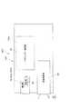
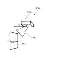
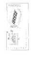
図1等に示すプロジェクターシステム500は、画像光である投射光PLを投射(斜方投射)して画像投射を行うプロジェクター100で構成されている。なお、投射光PLの被照射領域PLaは、例えばスクリーンSC上に形成される。被照射領域PLaは、プロジェクター100からの投射光(画像光)PLの投影領域に相当する。また、図示を省略するが、プロジェクターシステム500は、プロジェクター100のほか、例えばPC等が接続されることで構成され、必要に応じて当該PCが各種処理をすることで被照射領域PLaでの表示画面上への書込みを受け付けるインタラクティブな状況での画像動作を可能にしている。プロジェクターシステム500のうち、プロジェクター100は、スクリーンSCの斜め上方に設置され、斜め下方のスクリーンSCに向けて近接投射をする短焦点タイプ(ここでは、いわゆる超短焦点近接投射となっている。)のプロジェクターであり、画像投射を行うための本体部分であるプロジェクター本体部100pと、撮像部50とで構成されている。 A
プロジェクター本体部100pは、スクリーンSCに向けて可視光波長帯域の光を合成して構成される画像光である投射光PLを投射して投影画像(カラー画像)の形成を行う。プロジェクターシステム500において、インタラクティブな画像投射を可能にするためには、投射画面上における指示体の位置を特定するための位置合わせ(キャリブレーション)がなされていることが前提となる。このキャリブレーションについては、図14を参照して後述する。 The
プロジェクター本体部100pは、詳細な図示を省略するが、光源や光変調装置、投射光学系等を備え、スクリーンSCに対する画像投影を行う。このため、例えば図2に示すように、プロジェクター本体部100pは、投射光学系を含む画像投影部90と、プロジェクター制御部CTとを有し、プロジェクター制御部CTにより画像投射等の各種動作制御がなされている。また、特に、プロジェクター制御部CTは、撮像部50からの情報を撮像部50の通信部82を介して受け付け可能とし、撮像部50からの情報を加味して投射させる画像の内容を修正することで画面上に書込みができるものとなっている、すなわちインタラクティブな画像投射を可能としている。 Although not shown in detail, the projector
プロジェクター本体部100pを構成する光学系については、種々の態様が可能であるが、例えば光源等については、種々の構成のものが適用可能であり、例えばレーザー光源やLED光源、さらに有機EL(O−LED)を利用することも可能である。特に、有機EL素子等の自発光型の光源を適用した場合、光源が光変調の役割も兼ねた映像装置として構成できる。なお、光源(バックライト)と光変調とを個別の構成とする場合、光変調装置については、例えば透過型の液晶パネルとすることができる。 Various forms are possible for the optical system constituting the projector
図1に戻って、撮像部50は、プロジェクター本体部100pにより投射された投射画像を撮像して画像情報を取得するセンサー装置である。本実施形態では、特に、撮像部50は、離間して配置された2つ(複数)のカメラ50a,50bで構成されている。カメラ50a,50bは、同一規格の一対構成となっており、プロジェクター本体部100pによる投射光PLの投射位置に関して左右対称な位置に配置されている。各カメラ50a,50bは、例えば撮像レンズ系のほか、受光素子(撮像素子)すなわち受光用のセンサー、や通信部82(図2参照)による他の装置への送信等を含む各種制御を行う制御装置といったものを備える。以上のような複数のカメラ50a,50b(ステレオカメラ)を有することで、プロジェクター100は、視差情報(或いはステレオ画像)を取得可能となっている。すなわち、立体視によるより高度な位置検出が可能となっている。プロジェクター制御部CT(図2参照)は、撮像部50a,50bでの撮像により取得した画像情報に基づく視差情報により検出された指示体(利用者の指先等)OBの位置情報を反映させた画像を画像投影部90(図2参照)により投影させる。なお、2つのカメラ50a,50bは、プロジェクター100の投影画像位置を把握するための構成として、その役割を果たすため、例えばプロジェクター本体部100pによる画像投影における投射角度や投射距離等に対応した角度等にカメラのレンズ系が向いているように配置されている。すなわち、プロジェクター100の設置環境が変わって投射距離等が変化してもプロジェクター本体部100pと撮像部50との位置関係に変化が生じないあるいは生じても画像の補正等が可能な程度にわずかなものとなるようにしている。 Returning to FIG. 1, the
また、プロジェクター本体部100pは、撮像部50により取得された画像情報に基づいて、プロジェクター本体部100pを構成する画像形成部(光変調における画素マトリクス)の画素と撮像部50を構成する各カメラ50a,50bにそれぞれ内蔵される撮像素子(受光用のセンサー)の画素との位置関係を対応付けるキャリブレーションを可能にしている。 Further, the projector
なお、撮像部50は、プロジェクター100を構成する一部として組み込まれるものとすることもできるが、例えば、撮像部50は、プロジェクター100とは別体の撮像装置として存在するものとしてもよい。 Note that the
ここで、上記のように、本実施形態のプロジェクターシステム500では、いわゆる超短焦点近接投射を行っているため、プロジェクター本体部100pに近接して取り付けられる撮像部50(カメラ50a,50b)の撮影範囲を広くする必要がある。さらに、ステレオカメラ方式で、指示体である指について3次元位置を取得するという観点からも広画角なものとする必要がある。このような場合、通常のレンズを適用することが難しい可能性が高く、魚眼レンズを利用することが考えられる。魚眼レンズとしては、例えばfθレンズと呼ばれるレンズを用いた等距離射影方式を採用することが考えられる。しかしながら、このようなレンズを用いると、特に撮像画像の周辺側で大きな歪み(圧縮)が生じてしまう。歪み(圧縮)の影響が大きいと、検出されるべき対象である指先等の指示体OBがセンサー上の画像としては小さくなってしまい、誤検出や不検出を生じる可能性が高くなる。そこで、本実施形態では、撮像部50(カメラ50a,50b)において、次式で示される特性のレンズを用いて撮像を行う(立体射影方式)ものとしている。
y=2f・tan(θ/2)
ここで、焦点距離をf、半画角(あるいは単に画角)をθ、像高をyとする。
この場合、等距離射影方式に比べて、撮像画像において、特に周辺側での歪み(圧縮)を抑制できる。Here, as described above, in the
y = 2f · tan (θ / 2)
Here, the focal length is f, the half field angle (or simply the field angle) is θ, and the image height is y.
In this case, compared with the equidistant projection method, distortion (compression) particularly on the peripheral side can be suppressed in the captured image.
以下、図3等を参照して、撮像部50を構成する各カメラ50a,50bの撮像範囲に関して説明する。図3では、カメラ50aとカメラ50bとの対称性により1つのカメラのみを図示するとともに説明し、他方については説明を省略する。図示のように、本実施形態においては、カメラ50b(又はカメラ50a)の光軸AXは、プロジェクター本体部100pの被照射面であるスクリーンSCに対して垂直となっている。すなわち、カメラ50bは、あおりのない状態で撮像を行っている。本実施形態では、検出対象である指示体(指先)OBを2つのカメラ50a,50bによって視差を利用した立体的な検出を可能としている。すなわち、スクリーンSCをタッチする利用者の指手を撮像して奥行きのある立体的形状として捉えるための情報を得る必要がある。このため、スクリーンSC上の投影領域である被照射領域PLaに加え、被照射領域PLaを含む立体的領域を含むように撮像を行っている。本実施形態では、一例として、図示のように、スクリーンSCから垂直方向(奥行き方向)について、距離dだけ離れた範囲までを撮像範囲たる立体的領域CDとする。ここでは、指の先端から手首くらいまでを撮像できるように、距離dを160mm(16cm)とする。この場合、図4に示すように、立体的領域CDは、被照射領域PLaを底面とし、距離dを厚みとする直方体状の領域となる。したがって、撮像部50(カメラ50a,50b)の撮影範囲は、被照射領域PLaのみとした場合に比べてさらに広がり、特に広画角化する必要がある。広画角化が進むほど画像の周辺側が歪み、画像が小さくなりやすく、延いては、指示体たる手指の検出が困難になりやすい。これに対して、本実施形態では、上述のように、撮像部50(カメラ50a,50b)において立体射影方式を採用することで、かかる事態を回避している。 Hereinafter, with reference to FIG. 3 etc., the imaging range of each
以下、図5等を参照して、プロジェクター投影についての具体的一構成例(具体的仕様)について説明する。図5A及び5Bは、一例のプロジェクターにおける画像投射について示す図である。 Hereinafter, a specific configuration example (specific specification) for projector projection will be described with reference to FIG. 5A and 5B are diagrams illustrating image projection in an example projector.
ここでは、まず、図5Aを参照して、超短焦点近接投射の度合について説明する。プロジェクターにおけるスローレシオは、例えば図示の投射距離f1と、被照射領域PLaの横サイズHSとでf1/HSで表される。ここでの一例では、スローレシオは、約0.27とする。具体的には、投射距離f1は441mmであるものとし、横サイズHSの値を規定する被照射領域PLaのサイズは、70インチ(アスペクト比16:10)とする(すなわち、プロジェクター100は、70インチの画像を形成する)。なお、図5Bに示すように、この場合において、被照射領域PLaの周辺側の各点への投射光PLの投射角度を示している。この一例では、以上のような具体的仕様により超短焦点近接投射を行っている。 Here, first, with reference to FIG. 5A, the degree of ultra-short focus proximity projection will be described. The slow ratio in the projector is expressed by, for example, f1 / HS with the illustrated projection distance f1 and the lateral size HS of the irradiated area PLa. In this example, the slow ratio is about 0.27. Specifically, it is assumed that the projection distance f1 is 441 mm, and the size of the irradiated area PLa that defines the value of the horizontal size HS is 70 inches (aspect ratio 16:10) (that is, the
さらに、図6等を参照して、上記具体的一例の画像投射における撮像部50(カメラ50a,50b)の位置と撮像範囲の寸法について説明する。図6は、被照射領域PLaを含む撮像範囲である立体的領域CDと撮像部50を構成する1つのカメラのカメラ位置Paとの関係を示す図である。もう1つのカメラについては、左右の位置を逆転させたものとなるだけで同様の考察が可能であるため、図示及び説明を省略する。図6のうち、左側は、正面側から見た位置関係についての寸法を示す図であり、右側は、側面(横)側から見た位置関係についての寸法を示す図である。ここでは、図6に示すように、カメラ位置Paは、被照射領域PLaの左上方であり、例えば水平方向については、投射光PLの投射位置から左側に30cmほど離間している。この場合、カメラ位置Paからは、被照射領域PLaの右下側の位置SPが、撮像において最も周辺側となる。すなわち、当該箇所における指示体の検出が確実に行えるものとする必要があることになる。 Furthermore, with reference to FIG. 6 etc., the position of the imaging unit 50 (
なお、図示のように、検出範囲である立体的領域CDの上端面の領域を検出領域DD1とすると、これに対応するスクリーンSC上の領域は、破線で示す領域DLaとなる。すなわち、撮像部50は、検出領域DD1での検出を可能とするためには、スクリーンSC上で換算して領域DLaとなるような範囲についてまで撮像可能となっている必要がある。また、距離dの値が大きくなる(検出領域DD1が被照射領域PLaから遠くなる)につれて、領域DLaは急激に大きくなる。本構成では、超短焦点近接投射を行っているためである。以上のように、距離dの値が大きくなるほど、撮像部50を広画角化させる必要性が生じる。 As shown in the figure, when the region on the upper end surface of the three-dimensional region CD, which is the detection range, is a detection region DD1, the region on the screen SC corresponding to this is a region DLa indicated by a broken line. That is, in order to enable detection in the detection area DD1, the
図7は、撮像部50のうち上述した位置Paにあるカメラ(例えばカメラ50b)によって撮像された画像、すなわちカメラ50bに内蔵された受光用のセンサー上での画像の様子を示す図である。なお、ここでは、撮影された映像は、上下左右が反転しているため、スクリーンSCの右下の映像は、センサー上の画像において左上に来ている。したがって、図示の画像PIにおいて、スクリーンSC上の被照射領域PLaに対応する映像画像PLiのうち左上の隅にある画像点SPiが、図6の位置SPに対応する。なお、画像PIにおいて、映像画像DDiは、図6の検出領域DD1に対応する。カメラ50aは、これらの映像画像PLi,DDiが、センサー上のエリアSEのうち有効撮像範囲であるアクティブエリアAE内に収まるようにする必要がある。このため、図示のように、矩形領域を映した映像画像PLi,DDiは、歪めて撮像されたものとなっている。ここで、映像画像PLiは、指示位置が示される指示体の先端である指先を検出する必要があるが、映像画像PLiの領域のうち画像点SPi及びその近辺が、最も歪み、指示体の検出が最も困難になる箇所であると考えられる。したがって、この箇所での人の指幅について、撮像部50(カメラ50a,50b)として採用すべきカメラレンズの射影条件を変えて検討した。その結果、総合的に勘案して、立体射影方式で撮像を行うものを本実施形態の撮像部50(カメラ50a,50b)として採用することが最適であるとの結論に至った。 FIG. 7 is a diagram illustrating an image captured by the camera (for example, the
以下、上述した結論に至るまでに、画像点SPiに相当する位置での画像上(センサー上)で最小となる指幅の値に関して行った検証について説明する。そのための前提として、指示体たる指の姿勢(角度)について規定する。なお、標準的な指のサイズを考慮して、ここでは、直径10mmの円柱を指と見立てて検証を行った。図8A及び8Bは、指示体(指、あるいは直径10mmの円柱)OBのスクリーンSC(被照射領域PLa)上での角度の規定を示すものである。図8Aに示すように、スクリーンSC面に対する指示体OBの角度(仰角)を角度ηとする。また、図8Bに示すように、スクリーンSC面内において、横方向(水平方向)であるx方向について−x方向を基準(0°)として、反時計回りの角度(方位角)を角度φとする。 Hereinafter, until reaching the above-described conclusion, the verification performed on the minimum finger width value on the image (on the sensor) at the position corresponding to the image point SPi will be described. As a premise for this, the posture (angle) of the finger as the indicator is defined. In consideration of a standard finger size, here, a cylinder having a diameter of 10 mm was regarded as a finger and verified. 8A and 8B show the definition of the angle of the indicator (finger or cylinder having a diameter of 10 mm) OB on the screen SC (irradiated area PLa). As shown in FIG. 8A, an angle (elevation angle) of the indicator OB with respect to the screen SC surface is an angle η. Also, as shown in FIG. 8B, in the screen SC plane, the counterclockwise angle (azimuth angle) is defined as an angle φ with respect to the x direction, which is the horizontal direction (horizontal direction), with the −x direction as a reference (0 °). To do.
以上の角度η及び角度φによって向きが規定された指示体OBについて、角度η及び角度φの変化、すなわち姿勢の変化に対する画像上(センサー上)での幅(指幅に相当)の変化を、等距離射影と、立体射影と、通常の射影との3種類の射影条件について検証した。各射影条件は、
y=f・θ (等距離射影)
y=2f・tan(θ/2) (立体射影)
y=f・tanθ (通常の射影)
f:焦点距離、θ:半画角、y:像高
で表される。なお、各射影条件での画角(あるいは半画角θ)と像高yとの関係は、図9に示すグラフにおいて、曲線L1,L2,L3でそれぞれ示される。曲線L1は、立体射影方式、曲線L2は、等距離射影方式、曲線L3は、通常の射影方式について示している。また、この他の条件としては、例えば、上述したアクティブエリアAE(図7参照)に相当するセンサー有効エリアのサイズを、4.48mm×3.2mmとする。また、指示体OBの現実の幅は、既述の通り、10mmとする。For the indicator OB whose direction is defined by the above angle η and angle φ, the change in the angle η and the angle φ, that is, the change in the width (corresponding to the finger width) on the image (on the sensor) with respect to the change in posture, Three types of projection conditions of equidistant projection, three-dimensional projection, and normal projection were verified. Each projection condition is
y = f · θ (equal distance projection)
y = 2f · tan (θ / 2) (3D projection)
y = f · tanθ (normal projection)
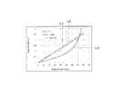
f: focal length, θ: half angle of view, y: image height. The relationship between the angle of view (or half angle of view θ) and the image height y under each projection condition is indicated by curves L1, L2, and L3 in the graph shown in FIG. A curve L1 shows a stereoscopic projection method, a curve L2 shows an equidistant projection method, and a curve L3 shows a normal projection method. As other conditions, for example, the size of the sensor effective area corresponding to the above-described active area AE (see FIG. 7) is set to 4.48 mm × 3.2 mm. The actual width of the indicator OB is 10 mm as described above.
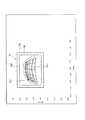
上記各射影条件のうち、立体射影方式、すなわち本実施形態における撮像部50による指示体OBの角度(姿勢)の変化と指示体の画像上の幅との関係については、図10に示されるものとなった。図10において、左側は、立体射影における撮像画像の様子を示しており、右側は、角度η及び角度φの変化に伴う画像点SPiを指し示した指示体の幅(指幅)の画像上での大きさ、すなわちセンサー上での幅(単位:μm)を示すグラフである。ここでは、角度(仰角)ηについては、0°〜90°、角度(方位角)φについては、0°〜180°の範囲での変化を計算している。図示のように、この場合、指幅の計算結果を見ると、角度η及び角度φが変化しても指幅が変わらず一定値を取っていることが分かった。なお、この場合の画像上(センサー上)での指示体の最小幅は、15.9μmであった。 Among the above projection conditions, the three-dimensional projection method, that is, the relationship between the change in the angle (posture) of the indicator OB by the
一方、一比較例として、上記各射影条件のうち、等距離射影方式における撮像部による指示体の角度(姿勢)の変化と指示体の画像上の幅との関係については、図11Aに示されるものとなった。この場合、角度η及び角度φが変化すると指幅も変わっていくことが分かった。なお、この場合の指示体の最小幅は、11.5μmであった。すなわち、この比較例では、上記した本実施形態の場合と比べて指示体の最小幅が著しく小さくなってしまうことが分かった。 On the other hand, as a comparative example, among the above projection conditions, the relationship between the change in the angle (posture) of the indicator by the imaging unit in the equidistant projection method and the width of the indicator on the image is shown in FIG. 11A. It became a thing. In this case, it was found that the finger width also changes as the angle η and the angle φ change. In this case, the minimum width of the indicator was 11.5 μm. That is, in this comparative example, it has been found that the minimum width of the indicator is remarkably reduced as compared with the case of the present embodiment described above.
また、別の一比較例として、上記各射影条件のうち、通常の投影方式すなわち魚眼レンズのようなものを適用しない場合における撮像部による指示体の角度(姿勢)の変化と指示体の画像上の幅との関係については、図11Bに示されるものとなった。なお、この場合、図中左側に示すように、撮像された画像は歪んでいない(あるいは略歪んでいない)ものとなる点において、上記2つの場合とは異なっている。この場合も、角度η及び角度φが変化すると指幅も変わっていくことが分かった。また、全体的に指幅は大きい(太い)ものとなっており、この場合の指示体の最小幅は、17.3μmであった(η=90°の時)。 As another comparative example, among the above projection conditions, a change in the angle (posture) of the indicator by the imaging unit when the normal projection method, that is, a fisheye lens is not applied, and the image of the indicator The relationship with the width is as shown in FIG. 11B. In this case, as shown on the left side of the figure, the captured image is not distorted (or not substantially distorted), and is different from the above two cases. Also in this case, it has been found that the finger width changes as the angle η and the angle φ change. In addition, the finger width as a whole is large (thick), and the minimum width of the indicator in this case is 17.3 μm (when η = 90 °).
以上において、画像上(センサー上)での指示体の最小幅だけを比較すると、図11Bに示す比較例が最もサイズが大きい状態を保っている。しかしながら、本実施形態でのプロジェクターシステム500の構成は、既述のように、超短焦点近接投射を行っていることが前提となっている。このため、撮像部50が広画角なものであることを要する。したがって、通常の射影方式を撮像部50に適用することは光学設計上非常に難しい。以上のことから本実施形態では、立体射影方式による撮像を行うものとした。 In the above description, when only the minimum width of the indicator on the image (on the sensor) is compared, the comparative example shown in FIG. 11B maintains the largest size. However, the configuration of the
以下、図12等を参照して、上記射影条件含む種々の射影条件について検討した結果を説明する。ここでは、射影条件を以下の式で表し、式中の係数(1/C)を0から1まで変えた時の最小指幅を計算した。
y=Cf・tan(θ/C)
なお、上式において、
C=∞、(1/C=0)のとき、y=f・θ(等距離射影)となり、
C=2、(1/C=0.5)のとき、y=2f・tan(θ/2)(立体射影)となり、
C=1、(1/C=1)のとき、y=f・tanθ (通常の射影)となる。
図12は、以上の結果についてまとめたグラフである。すなわち、図12の横軸は、係数(1/C)の値を示し、縦軸は、画像上(センサー上)での指示体の最小幅の値を示している。図12のグラフからも、立体射影方式によるものが、等距離射影方式あるいはこれに近い方式によるものよりも指示体の最小幅の値が大きなものに維持できものとなっていることが分かる。また、立体射影方式であれば、光学的設計が困難な通常の射影方式と比較して最小幅の値がそれほど変わらないものとなっていることも分かる。ただし、図12の横軸は、必ずしも光学的設計の難易度を示すものではない。そこで、光学的設計の難易度との相関性がより高いと考えられるディストーション(理想的な像高に対する各射影方式での実際の像高の比率)でも比較をした。図13は、画角80°とした場合のディストーションと画像上(センサー上)での指示体の最小幅との関係について示すグラフである。また、図中において、上記3種類の射影方式の位置を示してある。このグラフから、等距離射影方式と立体射影方式とは比較的近くにあることが分かる。すなわち、光学的設計の難易度にそれほど大きな差はないと考えられる。また、一方で、この間でのグラフの傾きが急であることが分かる。すなわち、両者を比較すると、立体射影方式では、レンズの設計難易度をあまり高くすることなく、画像上(センサー上)での指幅を大きくできることが分かる。Hereinafter, with reference to FIG. 12 etc., the result of having examined various projection conditions including the said projection conditions is demonstrated. Here, the projection condition was expressed by the following formula, and the minimum finger width when the coefficient (1 / C) in the formula was changed from 0 to 1 was calculated.
y = Cf · tan (θ / C)
In the above formula,
When C = ∞ and (1 / C = 0), y = f · θ (equal distance projection)
When C = 2 and (1 / C = 0.5), y = 2f · tan (θ / 2) (stereoscopic projection) is obtained.
When C = 1 and (1 / C = 1), y = f · tan θ (normal projection).
FIG. 12 is a graph summarizing the above results. That is, the horizontal axis of FIG. 12 indicates the value of the coefficient (1 / C), and the vertical axis indicates the value of the minimum width of the indicator on the image (on the sensor). From the graph of FIG. 12, it can be seen that the three-dimensional projection method can maintain the value of the minimum width of the indicator larger than that of the equidistant projection method or a method close thereto. It can also be seen that the minimum projection value does not change so much with the stereoscopic projection method as compared with the normal projection method in which optical design is difficult. However, the horizontal axis in FIG. 12 does not necessarily indicate the difficulty of optical design. Therefore, a comparison was also made with distortion (the ratio of the actual image height in each projection method to the ideal image height) that is considered to have a higher correlation with the difficulty of optical design. FIG. 13 is a graph showing the relationship between the distortion when the angle of view is 80 ° and the minimum width of the indicator on the image (on the sensor). In the drawing, the positions of the above three types of projection methods are shown. From this graph, it can be seen that the equidistant projection method and the three-dimensional projection method are relatively close to each other. That is, it is considered that there is no great difference in the difficulty of optical design. On the other hand, it can be seen that the slope of the graph during this period is steep. That is, comparing the two, it can be seen that the three-dimensional projection method can increase the finger width on the image (on the sensor) without increasing the lens design difficulty.
以下、図14を参照して、インタラクティブな画像投射を可能にするための前提となる位置合わせの処理であるキャリブレーションについて説明する。図14は、プロジェクター本体部100pによる画像投影のうち、特に、上述のようなキャリブレーションの処理を行うために、キャリブレーション時のパターン画像を投影する様子を示している。本実施形態では、まず、プロジェクター本体部100pによる画像投射(投影)によってスクリーンSC上に映し出される映像の範囲を示すパターン画像PTを、ここでは画像光である投射光PLに含まれる可視光波長帯域の成分のうち緑色波長帯域の光で構成されるパターン画像光GLによって投影するものとする。撮像部50において、パターン画像光GLの一部の成分を受光することで、パターン画像PTに関する画像情報が取得され、この情報に基づき画像投射位置の特定がなされる。具体的には、まず、撮像部50は、撮像したパターン画像PTの画像情報をプロジェクター本体部100pに対して送信する。次に、プロジェクター本体部100pは、撮像部50で取得したパターン画像PTの情報と、光変調における画素マトリクスの情報との対応付けを行う。すなわち、撮像部50で撮像されたパターン画像PTの受光用のセンサー上での各位置とプロジェクター本体部100pの光変調における画素マトリクス状の各位置すなわち投影された画像上の位置とを対応付ける。対応付けは、例えば、ピクセル単位で行うものとしてもよい(例えば対応するテーブルを作成するものとしてもよい)が、例えば対応付ける関数を定めることで、対応付けの処理を可能にするものとしてもよい。 Hereinafter, with reference to FIG. 14, a description will be given of calibration, which is an alignment process that is a prerequisite for enabling interactive image projection. FIG. 14 shows a state in which a pattern image at the time of calibration is projected in order to perform the above-described calibration processing among the image projections by the projector
以上のように、プロジェクター本体部100pは、撮像部50で取得したパターン画像PTの情報に基づく画像投射位置と、光変調の画素の位置とを対応付けることで、キャリブレーション(位置合わせ)を行っている。キャリブレーション後は、キャリブレーションでの対応付けに基づいて、撮像部50で検出された指示体OBによる指示位置の特定が可能となり、これを反映したインタラクティブな画像投射が可能となる。 As described above, the projector
以上のように、本実施形態に係るプロジェクターシステム500では、撮像部50を立体射影方式とすることにより画角を広げ、斜方投射された画像光(投射光)による投影領域(被照射領域PLa)のみならず投影領域を含む立体的領域CDまでを撮像可能とし、さらに、立体的領域CDに存する指示体OBを確実に捉えることができる。特に、撮像部50において立体射影方式を採用することで、撮像部50の光学的設計の難易度を抑えつつ、指示体OBの角度η,φが変化しても指示体OBが画像上において歪んで小さくなることを回避し、指示体OBの位置を確実に検出できる。 As described above, in the
〔第2実施形態〕
以下、図15を参照して、第1実施形態を変形した第2実施形態について説明する。なお、本実施形態に係るプロジェクターシステムは、撮像部50の姿勢(あおり角)を変化させる構成となっていることを除いて、第1実施形態と同様の構成であるので、プロジェクターシステム全体の図示及び説明を省略する。また、具体的一構成例(具体的仕様)についても第1実施形態において示した場合と同様であるものとする。ただし、本実施形態では、あおり角を変化させるため、あおり角の増減に伴って焦点距離fが変化する点において、第1実施形態とは異なる(第1実施形態では、あおり角0°のため、焦点距離fは不変である。)。[Second Embodiment]
Hereinafter, a second embodiment obtained by modifying the first embodiment will be described with reference to FIG. The projector system according to the present embodiment has the same configuration as that of the first embodiment except that the posture (tilt angle) of the
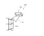
図15は、本実施形態のプロジェクターシステムにおける撮像部150の姿勢及び撮影範囲ついて説明するための図であり、図3に対応する図である。なお、撮像部150は、第1実施形態の場合と同様に、2つのカメラ150a,150bで構成されているものとする。図3と比較して明らかなように、図15に例示する本実施形態における撮像部150において、カメラ150b(又はカメラ150a)の光軸AXは、スクリーンSCに対して垂直ではなく、下方に少し傾いている。すなわち、カメラ150aは、あおりを付けた状態で撮像を行っている。この場合、適度にあおり角度を増加させることで、第1実施形態のようにあおり角がない(0°)の場合に比べて撮像部150において撮像に必要となる最大画角を小さくできる。ここでは、一例として、あおり角α=10°とする。 FIG. 15 is a diagram for explaining the posture and imaging range of the
図16は、第1実施形態と同様の具体的一構成例(具体的仕様)における本実施形態の撮像部150(立体射影方式)による指示体の角度(姿勢)の変化と指示体の画像上の幅との関係について説明するための図及びグラフである。すなわち、図16は、図10に対応するものである。この場合も、指幅の計算結果を見ると、図8A及び8Bを参照して規定した角度η及び角度φが変化しても、指幅が変わらず一定値を取っていることが分かった。なお、この場合の指示体の最小幅は、14.9μmであった。この場合、図10と比較すると、わずかに値が小さくなっている。 FIG. 16 shows the change in the angle (posture) of the indicator by the imaging unit 150 (stereoscopic projection method) of this embodiment and the image of the indicator in a specific configuration example (specific specification) similar to the first embodiment. It is the figure and graph for demonstrating the relationship with the width | variety. That is, FIG. 16 corresponds to FIG. Also in this case, it was found from the calculation result of the finger width that even if the angle η and the angle φ defined with reference to FIGS. 8A and 8B change, the finger width does not change and takes a constant value. In this case, the minimum width of the indicator was 14.9 μm. In this case, the value is slightly smaller than in FIG.
ここで、上記のように、ある程度のあおり角αを有することで撮像部150の最大画角を小さくできるので、カメラレンズの設計難易度を下げることができる。ただし、その一方で、あおり角を増加させると、指示体の最小幅(指幅)は小さくなる。すなわち、カメラレンズの設計難易度の緩和と、指幅を太く(大きく)させることは背反する。したがって、バランス取りが必要になり、このため、ここでの例示としては、上記のように、あおり角αの値を10°としている。なお、この値(あおり角α=10°)は、本実施形態における具体的一構成例(具体的仕様)において最適と考えられる範囲内の値の1つである。図17は、上記の場合における撮像部150のあおり角αと撮像に必要となる最大画角との関係について示すグラフである。グラフから、最大画角は、あおり角αが0°から下がり、10°となる付近までは傾き(下がり具合)が大きく、10°前後ではある程度の範囲で略横ばいの状態が続いていることが読み取れる。このことから、例えば10°±5°程度の範囲であれば、設計難易度を緩和させやすいものとなっていることが分かる。また、図18は、上記した3種類の射影条件でのあおり角と指示体の最小幅(指幅)との関係について示すグラフである。曲線C1が本実施形態で採用する立体射影方式を示し、曲線C2が等距離射影方式を示し、曲線C3が通常の射影方式を示している。グラフから、立体射影方式において、あおり角αを増加させると指示体の最小幅(指幅)が小さくなることが分かるが、あおり角αが5°を超える範囲では、3つの方式の中で立体射影方式の最小幅(指幅)が最も大きくなっていることが分かる。 Here, as described above, since the maximum angle of view of the
なお、上述のように、あおり角αを10°とするのは、本実施形態の具体的一構成例(具体的仕様)に起因し、構成例によっては、最適な角度が多少異なる場合もある。しかしながら、傾向としては同様であるものと考えられ、例えばあおり角αを10°の前後の値として、例えば10°±5°とすることで、撮像部の最大画角を抑えつつ指示体の確実な検出を維持できる。 As described above, the tilt angle α is set to 10 ° because of a specific configuration example (specific specification) of the present embodiment, and the optimum angle may be slightly different depending on the configuration example. . However, it is considered that the tendency is the same. For example, by setting the tilt angle α to a value before and after 10 °, for example, 10 ° ± 5 °, it is possible to reliably display the indicator while suppressing the maximum angle of view of the imaging unit. Accurate detection can be maintained.
以上のように、本実施形態に係るプロジェクターシステムにおいても、撮像部150を立体射影方式とすることにより、撮像部150の光学的設計の難易度を抑えつつ、被写体たる指示体が画像上において歪んで小さくなることを回避し、指示体の位置を確実に検出できる。 As described above, also in the projector system according to the present embodiment, the
また、既述のように、あおり角を増加させると、指示体の最小幅(指幅)は小さくなる傾向にある。したがって、例えばプロジェクターにおけるスローレシオがより小さく、撮像部の画角を広くする必要がある場合には、本実施形態(第2実施形態)に示したように、あおり角を設けることで撮像部の広画角化を抑制でき、有効であると考えられる。一方、プロジェクターのスローレシオが比較的大きめの場合にはそれほど広い画角が要求されないため、あおり角を積極的に設けるよりは、例えば第1実施形態のようにあおり角を設けない、あるいはあおり角を小さな値に抑えて、指の幅を広くとれることを優先するほうがよいと考えられる。 Further, as described above, when the tilt angle is increased, the minimum width (finger width) of the indicator tends to be reduced. Therefore, for example, when the slow ratio in the projector is smaller and it is necessary to widen the angle of view of the imaging unit, as shown in the present embodiment (second embodiment), the tilt angle is provided to provide It is possible to suppress the wide angle of view and is considered effective. On the other hand, when the slow ratio of the projector is relatively large, a very wide angle of view is not required. Therefore, rather than positively setting the tilt angle, for example, the tilt angle is not provided or the tilt angle is not provided as in the first embodiment. It is considered better to give priority to widening the finger width while keeping the value small.
〔その他〕
この発明は、上記の各実施形態に限られるものではなく、その要旨を逸脱しない範囲において種々の態様で実施することが可能である。[Others]
The present invention is not limited to the above embodiments, and can be implemented in various modes without departing from the scope of the invention.
上記では、具体的一構成例(具体的仕様)に即して説明しているが、これはあくまで一例であり、構成例については種々の多様な場合が考えられる。例えば、上記では、70インチの被照射領域(投影領域)を形成するものとしているが、70インチ以上(例えば70インチ〜120インチ程度)とすることが考えられる。また、例えば立体的領域CDの奥行き方向について、距離dを160mm(16cm)としているが、16cm以上とすることも考えられる。また、近接投射に関して、スローレシオを約0.27としているが、例えば0.27以下とする構成にしてもよい。その他にも、例えば、プロジェクター100における投射距離f1を異なる値とすることも考えられる。 In the above description, a specific configuration example (specific specification) is described. However, this is merely an example, and various various cases can be considered for the configuration example. For example, in the above, an irradiation area (projection area) of 70 inches is formed, but it is conceivable that the irradiation area is 70 inches or more (for example, about 70 inches to 120 inches). Further, for example, the distance d is set to 160 mm (16 cm) in the depth direction of the three-dimensional area CD, but it may be set to 16 cm or more. Further, regarding the proximity projection, the slow ratio is set to about 0.27, but may be configured to be 0.27 or less, for example. In addition, for example, it is also conceivable to set the projection distance f1 in the
また、上記では、撮像部50を構成する一対のカメラ50a,50bから取得された画像情報に基づく視差情報によって指示体を立体的形状として捉えることができる。この際、各カメラ50a,50bからの画像情報は、キャリブレーションでの対応付けに基づいてそれぞれ画像処理が施されるものとなる。この画像処理については、各カメラ50a,50bからの画像情報ごとに個別に行うものとしてもよいが、一対のカメラ50a,50bは、左右の対称性を有していることを利用して、一方の処理方法を、左右反転させて他方に転用するものとしてもよい。また、この場合、2つの画像処理を一括して行うものとしてもよい。 Further, in the above, the indicator can be regarded as a three-dimensional shape by the parallax information based on the image information acquired from the pair of
また、上記では、プロジェクター制御部CTや、プロジェクター100に接続可能なPC等において各種処理をなすものとして記載しているが、担わせる処理については、種々の態様が可能であり、例えば、撮像部50で取得した投射光PLの情報に基づく画像投射位置と、撮像部50により検出された検出光DLに基づく位置とを特定する等の処理をPC側で行うようにするといったことが考えられる。言い換えると、プロジェクター制御部CTにおける上記画像投射位置や指示体による指示位置を特定し、特定した位置関係に基づく画像投影の制御の一部又は全部をPC等の外部接続機器で行う(PC等がプロジェクター制御部を構成する)ものとしてもよい。また、逆に、PC等を接続せず、例えば、プロジェクター制御部CTにおいて全ての処理を担わせる構成(PCレス)とすることも可能である。 In the above description, the projector control unit CT and the PC that can be connected to the
また、上記では、キャリブレーションにおいて、パターン画像PTを緑色波長帯域の光で構成されるパターン画像光GLによって投影するものとしているが、パターン画像PTの投影については、緑色波長帯域の光に限らず、他の波長帯域の光を利用することも考えられる。 In the above description, in the calibration, the pattern image PT is projected by the pattern image light GL composed of light in the green wavelength band. However, the projection of the pattern image PT is not limited to light in the green wavelength band. It is also conceivable to use light in other wavelength bands.
また、上記では、プロジェクター本体部100pを構成する光源や光変調装置、投射光学系等については、図示や詳細な説明を省略しているが、種々の態様が適用可能であり、例えば光源に関しては、上記のほか、例えば高圧水銀ランプ等を利用し、3色の光源に分離して適用することも可能である。光変調装置については、上記のほか、例えば光変調装置についても液晶パネルにカラーフィルターを利用したものや、反射型液晶パネル、デジタル・マイクロミラー・デバイス等により構成するといった種々の態様が考えられる。 In the above description, illustration and detailed description of the light source, the light modulation device, the projection optical system, and the like constituting the projector
50…撮像部、50a,50b…カメラ、82…通信部、90…画像投影部、100…プロジェクター、100p…プロジェクター本体部、150…撮像部、150a,150b…カメラ、500…プロジェクターシステム、AE…アクティブエリア、AX…光軸、C1…曲線、C2…曲線、C3…曲線、CD…立体的領域、CT…プロジェクター制御部、d…距離、DD1…検出領域、DDi…映像画像、DL…検出光、DLa…領域、f…焦点距離、f1…投射距離、GL…パターン画像光、HS…横サイズ、L1,L2,L3…曲線、OB…指示体、Pa…カメラ位置、Pa…位置、PI…画像、PL…投射光、PLa…被照射領域、PLi…映像画像、PT…パターン画像、SC…スクリーン、SE…エリア、SP…位置、SPi…画像点、y…像高、η,φ…角度、θ…半画角(画角) DESCRIPTION OF
Claims (8)
Translated fromJapanese前記プロジェクター本体部からの画像光の投影領域を含む立体的領域を撮像して前記立体的領域に存する指示体を検出可能にする立体射影方式の撮像部と
を備えるプロジェクターシステム。A projector main body that projects image light obliquely;
A projector system comprising: a stereoscopic projection imaging unit that images a stereoscopic region including a projection region of image light from the projector main body and detects an indicator existing in the stereoscopic region.
Priority Applications (4)
| Application Number | Priority Date | Filing Date | Title |
|---|---|---|---|
| JP2016225729AJP2018085552A (en) | 2016-11-21 | 2016-11-21 | Projector system |
| US16/462,363US10754474B2 (en) | 2016-11-21 | 2017-11-06 | Projector system |
| PCT/JP2017/039969WO2018092627A1 (en) | 2016-11-21 | 2017-11-06 | Projector system |
| CN201780071664.9ACN109983764A (en) | 2016-11-21 | 2017-11-06 | Projecting apparatus system |
Applications Claiming Priority (1)
| Application Number | Priority Date | Filing Date | Title |
|---|---|---|---|
| JP2016225729AJP2018085552A (en) | 2016-11-21 | 2016-11-21 | Projector system |
Publications (2)
| Publication Number | Publication Date |
|---|---|
| JP2018085552Atrue JP2018085552A (en) | 2018-05-31 |
| JP2018085552A5 JP2018085552A5 (en) | 2019-10-31 |
Family
ID=62145513
Family Applications (1)
| Application Number | Title | Priority Date | Filing Date |
|---|---|---|---|
| JP2016225729AWithdrawnJP2018085552A (en) | 2016-11-21 | 2016-11-21 | Projector system |
Country Status (4)
| Country | Link |
|---|---|
| US (1) | US10754474B2 (en) |
| JP (1) | JP2018085552A (en) |
| CN (1) | CN109983764A (en) |
| WO (1) | WO2018092627A1 (en) |
Families Citing this family (5)
| Publication number | Priority date | Publication date | Assignee | Title |
|---|---|---|---|---|
| US11196985B1 (en) | 2018-12-28 | 2021-12-07 | Facebook, Inc. | Surface adaptation for projection-based augmented reality system |
| US11172189B1 (en) | 2018-12-28 | 2021-11-09 | Facebook, Inc. | User detection for projection-based augmented reality system |
| JP2022014630A (en)* | 2020-07-07 | 2022-01-20 | ソニーセミコンダクタソリューションズ株式会社 | Image display device and control method |
| CN112672125B (en)* | 2020-12-24 | 2022-02-01 | 四川长虹电器股份有限公司 | Image matching system and method for laser television |
| CN114863136B (en)* | 2022-05-25 | 2024-11-19 | 中国人民解放军陆军炮兵防空兵学院 | Anchor-free target detection method and system based on diagonal network |
Citations (9)
| Publication number | Priority date | Publication date | Assignee | Title |
|---|---|---|---|---|
| JPH08328735A (en)* | 1995-06-02 | 1996-12-13 | Takenaka Komuten Co Ltd | Hand pointing input device |
| JP2010282463A (en)* | 2009-06-05 | 2010-12-16 | Newcom Inc | Touch panel device |
| JP2012038025A (en)* | 2010-08-05 | 2012-02-23 | Canon Inc | Display device, control method for display device, and program |
| JP2013084156A (en)* | 2011-10-11 | 2013-05-09 | Honda Motor Co Ltd | Image processing method |
| JP2013120365A (en)* | 2011-12-09 | 2013-06-17 | Samsung Yokohama Research Institute Co Ltd | Projection optical system and image projection device |
| JP2014067349A (en)* | 2012-09-27 | 2014-04-17 | Seiko Epson Corp | Human interface device and method |
| JP2014137483A (en)* | 2013-01-17 | 2014-07-28 | Canon Inc | Zoom lens and imaging device |
| JP2015043154A (en)* | 2013-08-26 | 2015-03-05 | キヤノン株式会社 | Information processing device, control method therefor, computer program, and storage medium |
| JP2015156633A (en)* | 2014-02-19 | 2015-08-27 | 中強光電股▲ふん▼有限公司 | Projection system and projection method thereof |
Family Cites Families (24)
| Publication number | Priority date | Publication date | Assignee | Title |
|---|---|---|---|---|
| JP2992547B2 (en) | 1990-07-09 | 1999-12-20 | チノン株式会社 | Super wide angle lens |
| US20030071813A1 (en)* | 1996-06-05 | 2003-04-17 | Alessandro Chiabrera | Three-dimensional display system: apparatus and method |
| JP4416391B2 (en) | 2002-11-22 | 2010-02-17 | 株式会社リコー | Wide-angle lens, camera and projection display device |
| US7986321B2 (en)* | 2008-01-02 | 2011-07-26 | Spatial Integrated Systems, Inc. | System and method for generating structured light for 3-dimensional image rendering |
| US9495013B2 (en)* | 2008-04-24 | 2016-11-15 | Oblong Industries, Inc. | Multi-modal gestural interface |
| US8152313B2 (en)* | 2008-05-09 | 2012-04-10 | Sanyo Electric Co., Ltd. | Projection display device that displaces an optical position of an imager in conjunction with a focus adjustment |
| KR20120084775A (en)* | 2009-10-30 | 2012-07-30 | 휴렛-팩커드 디벨롭먼트 컴퍼니, 엘.피. | Stereo display systems |
| JP2011180712A (en)* | 2010-02-26 | 2011-09-15 | Sanyo Electric Co Ltd | Projection type image display apparatus |
| CN103858074B (en)* | 2011-08-04 | 2018-10-19 | 视力移动技术有限公司 | Systems and methods for interacting with devices via 3D displays |
| JP5871743B2 (en)* | 2012-07-31 | 2016-03-01 | キヤノン株式会社 | Imaging optical system, and projection-type image display device and imaging device using the same |
| JP2014179032A (en)* | 2013-03-15 | 2014-09-25 | Ricoh Co Ltd | Virtual key input device |
| JP6417690B2 (en)* | 2014-01-21 | 2018-11-07 | セイコーエプソン株式会社 | Projector, display device, and projector control method |
| CN104049747B (en)* | 2014-01-24 | 2017-02-08 | 胡世曦 | Mouse device for directly controlling cursor with finger |
| CN104020957B (en)* | 2014-06-20 | 2017-04-05 | 北京工业大学 | Digital types of facial makeup in Beijing operas stereoprojection interactive system |
| JP2016162162A (en)* | 2015-03-02 | 2016-09-05 | 株式会社リコー | Contact detection device, projector device, electronic blackboard device, digital signage device, projector system, and contact detection method |
| JP6477130B2 (en)* | 2015-03-27 | 2019-03-06 | セイコーエプソン株式会社 | Interactive projector and interactive projection system |
| US10067569B2 (en)* | 2015-08-14 | 2018-09-04 | Fresenius Medical Care Holdings, Inc. | Touchless interface for a medical treatment system |
| JP6198862B2 (en) | 2016-01-14 | 2017-09-20 | キヤノン株式会社 | Imaging optical system, and projection-type image display device and imaging device using the same |
| JP6249248B2 (en)* | 2016-03-10 | 2017-12-20 | パナソニックIpマネジメント株式会社 | Projection device |
| JP6756149B2 (en)* | 2016-05-18 | 2020-09-16 | セイコーエプソン株式会社 | projector |
| JP2018056800A (en)* | 2016-09-29 | 2018-04-05 | セイコーエプソン株式会社 | Projector system |
| JP6892286B2 (en)* | 2017-03-03 | 2021-06-23 | 株式会社キーエンス | Image processing equipment, image processing methods, and computer programs |
| JP6822234B2 (en)* | 2017-03-15 | 2021-01-27 | セイコーエプソン株式会社 | Projector system |
| JP6972609B2 (en)* | 2017-03-28 | 2021-11-24 | セイコーエプソン株式会社 | Light emitting device and image display system |
- 2016
- 2016-11-21JPJP2016225729Apatent/JP2018085552A/ennot_activeWithdrawn
- 2017
- 2017-11-06CNCN201780071664.9Apatent/CN109983764A/ennot_activeWithdrawn
- 2017-11-06USUS16/462,363patent/US10754474B2/enactiveActive
- 2017-11-06WOPCT/JP2017/039969patent/WO2018092627A1/ennot_activeCeased
Patent Citations (9)
| Publication number | Priority date | Publication date | Assignee | Title |
|---|---|---|---|---|
| JPH08328735A (en)* | 1995-06-02 | 1996-12-13 | Takenaka Komuten Co Ltd | Hand pointing input device |
| JP2010282463A (en)* | 2009-06-05 | 2010-12-16 | Newcom Inc | Touch panel device |
| JP2012038025A (en)* | 2010-08-05 | 2012-02-23 | Canon Inc | Display device, control method for display device, and program |
| JP2013084156A (en)* | 2011-10-11 | 2013-05-09 | Honda Motor Co Ltd | Image processing method |
| JP2013120365A (en)* | 2011-12-09 | 2013-06-17 | Samsung Yokohama Research Institute Co Ltd | Projection optical system and image projection device |
| JP2014067349A (en)* | 2012-09-27 | 2014-04-17 | Seiko Epson Corp | Human interface device and method |
| JP2014137483A (en)* | 2013-01-17 | 2014-07-28 | Canon Inc | Zoom lens and imaging device |
| JP2015043154A (en)* | 2013-08-26 | 2015-03-05 | キヤノン株式会社 | Information processing device, control method therefor, computer program, and storage medium |
| JP2015156633A (en)* | 2014-02-19 | 2015-08-27 | 中強光電股▲ふん▼有限公司 | Projection system and projection method thereof |
Also Published As
| Publication number | Publication date |
|---|---|
| US20190324571A1 (en) | 2019-10-24 |
| US10754474B2 (en) | 2020-08-25 |
| CN109983764A (en) | 2019-07-05 |
| WO2018092627A1 (en) | 2018-05-24 |
Similar Documents
| Publication | Publication Date | Title |
|---|---|---|
| WO2018092627A1 (en) | Projector system | |
| KR102463712B1 (en) | Virtual touch recognition apparatus and method for correcting recognition error thereof | |
| CN101656858B (en) | Projection display apparatus and display method | |
| TWI547828B (en) | Calibration of sensors and projector | |
| US9891442B2 (en) | Variable curvature display device and displaying method thereof | |
| KR101669780B1 (en) | Method and device for controlling projection of wearable apparatus, and wearable apparatus | |
| JP5401940B2 (en) | Projection optical system zoom ratio measurement method, projection image correction method using the zoom ratio measurement method, and projector for executing the correction method | |
| US9946146B2 (en) | Control apparatus configured to control projection of an image based on position information, projection information, and shape information, corresponding control method and corresponding storage medium | |
| CN102193287B (en) | Projection method and projection system | |
| US10516864B2 (en) | Projector system | |
| CN105706028A (en) | Projection type image display device | |
| CN102595178B (en) | Field stitching three dimensional rendered images corrective system and bearing calibration | |
| CN107852474A (en) | Head mounted display | |
| US20130241883A1 (en) | Optical touch system and optical touch-position detection method | |
| CN109073363B (en) | Image recognition device, image recognition method, and image recognition unit | |
| WO2011136213A1 (en) | Display device | |
| US10891750B2 (en) | Projection control device, marker detection method, and storage medium | |
| TWI564773B (en) | Optical touch system and optical touch apparatus thereof | |
| JP2018085553A (en) | Projector system | |
| US20130241882A1 (en) | Optical touch system and optical touch position detecting method | |
| JP2017129767A (en) | Reflector, method of adjusting light-emitting device, and detection system | |
| JP2015142157A (en) | Image projection system, projection controller, projection controlling program | |
| TWI543046B (en) | Optical touch system | |
| JP2014233005A (en) | Image display apparatus | |
| JP2006214922A (en) | Image processing system, projector, program, information storage medium, and image processing method |
Legal Events
| Date | Code | Title | Description |
|---|---|---|---|
| RD05 | Notification of revocation of power of attorney | Free format text:JAPANESE INTERMEDIATE CODE: A7425 Effective date:20180907 | |
| RD03 | Notification of appointment of power of attorney | Free format text:JAPANESE INTERMEDIATE CODE: A7423 Effective date:20181120 | |
| A521 | Request for written amendment filed | Free format text:JAPANESE INTERMEDIATE CODE: A523 Effective date:20190918 | |
| A621 | Written request for application examination | Free format text:JAPANESE INTERMEDIATE CODE: A621 Effective date:20190918 | |
| RD07 | Notification of extinguishment of power of attorney | Free format text:JAPANESE INTERMEDIATE CODE: A7427 Effective date:20200803 | |
| A131 | Notification of reasons for refusal | Free format text:JAPANESE INTERMEDIATE CODE: A131 Effective date:20201117 | |
| A761 | Written withdrawal of application | Free format text:JAPANESE INTERMEDIATE CODE: A761 Effective date:20210118 |