JP2018084726A - Optical device and projector - Google Patents
Optical device and projectorDownload PDFInfo
- Publication number
- JP2018084726A JP2018084726AJP2016228640AJP2016228640AJP2018084726AJP 2018084726 AJP2018084726 AJP 2018084726AJP 2016228640 AJP2016228640 AJP 2016228640AJP 2016228640 AJP2016228640 AJP 2016228640AJP 2018084726 AJP2018084726 AJP 2018084726A
- Authority
- JP
- Japan
- Prior art keywords
- flow path
- liquid
- frame
- optical
- optical device
- Prior art date
- Legal status (The legal status is an assumption and is not a legal conclusion. Google has not performed a legal analysis and makes no representation as to the accuracy of the status listed.)
- Withdrawn
Links
Images


Landscapes
- Projection Apparatus (AREA)
- Cooling Or The Like Of Electrical Apparatus (AREA)
Abstract
Translated fromJapaneseDescription
Translated fromJapanese本発明は、光学装置およびプロジェクターに関する。 The present invention relates to an optical device and a projector.
従来、光源装置から射出された光を画像情報に応じて変調し、スクリーン等の投写面に画像を投写するプロジェクターが知られている。また、近年、より明るい画像の投写を可能とするために、より高輝度の光を射出する光源装置を備えたプロジェクターが知られている。そして、このようなプロジェクターにおいては、光源装置から射出された光が入射する光学素子の発熱が顕著になるため、液体を用いてこの光学素子を冷却する技術が提案されている(例えば、特許文献1参照)。 Conventionally, a projector that modulates light emitted from a light source device according to image information and projects an image on a projection surface such as a screen is known. In recent years, there has been known a projector including a light source device that emits light with higher luminance in order to enable projection of a brighter image. In such a projector, since the heat generated by the optical element to which the light emitted from the light source device enters becomes remarkable, a technique for cooling the optical element using a liquid has been proposed (for example, Patent Documents). 1).
特許文献1に記載のプロジェクターは、光学素子(液晶パネル)を有する光学装置と、液冷装置とを備える。光学装置は、液晶パネルに加え、この液晶パネルを保持する光学素子保持体を備える。
光学素子保持体は、開口部を有し、液晶パネルを支持するパネル支持枠と、液体流通管と、を備える。液体流通管は、U字状に屈曲され、液晶パネルの画像形成領域を平面視で3方向において囲むように形成され、内部に液体が流通する。パネル支持枠は、液体流通管を挟持する入射側支持枠および出射側支持枠を備える。
液冷装置は、液体圧送部と、タンクと、熱交換ユニットと、複数の液体循環部材と、を備え、液体流通管に液体を循環させる。The projector described in Patent Document 1 includes an optical device having an optical element (liquid crystal panel) and a liquid cooling device. The optical device includes an optical element holder that holds the liquid crystal panel in addition to the liquid crystal panel.
The optical element holder has an opening, and includes a panel support frame that supports the liquid crystal panel, and a liquid circulation pipe. The liquid circulation pipe is bent in a U shape and is formed so as to surround the image forming area of the liquid crystal panel in three directions in plan view, and the liquid circulates therein. The panel support frame includes an incident side support frame and an output side support frame that sandwich the liquid circulation pipe.
The liquid cooling device includes a liquid pumping unit, a tank, a heat exchange unit, and a plurality of liquid circulation members, and circulates the liquid through the liquid circulation pipe.
しかしながら、特許文献1に記載の技術では、液体流通管が液晶パネルの画像形成領域を3方向において囲むように形成されていることにより、残りの1方向においては、液体が流通されないため、冷却が不十分になるという課題がある。そこで、冷却の能力を向上させるために、液体流通管を太くして液体の流量を増やす方法や、液体流通管の曲げか所を増やして画像形成領域を略4方向において囲むように構成する方法があるが、以下の課題がある。すなわち、液体流通管を太くすると、光学素子保持体、ひいては光学装置が大型化するという課題がある。液体流通管の曲げか所を増やすと、加工が難しいことや、高圧で液体を流通させる必要があり、液体圧送部に高パワーのものが求められると共に圧力損失が大きくなる。圧力損失が大きくなると、液体を循環させるための接続部材間からの液体の揮発や漏れが生じ易くなるため、漏れた液体がプロジェクター内の他の部材に付着して不具合が発生する恐れがあることや、蓄積する液体を多くする必要があるため、タンクが大型化するという課題がある。 However, in the technique described in Patent Document 1, since the liquid circulation tube is formed so as to surround the image forming region of the liquid crystal panel in three directions, the liquid is not circulated in the remaining one direction. There is a problem of becoming insufficient. Therefore, in order to improve the cooling capability, a method of increasing the flow rate of the liquid by increasing the thickness of the liquid circulation pipe, or a method of increasing the number of bent portions of the liquid circulation pipe so as to surround the image forming area in approximately four directions. However, there are the following problems. That is, when the liquid circulation pipe is thickened, there is a problem that the optical element holder, and thus the optical device, is increased in size. If the number of bent portions of the liquid circulation pipe is increased, it is difficult to process and it is necessary to circulate the liquid at a high pressure, so that a high power is required for the liquid pumping section and the pressure loss increases. When the pressure loss increases, the liquid tends to volatilize or leak from between the connection members for circulating the liquid, and the leaked liquid may adhere to other members in the projector and cause problems. Moreover, since it is necessary to increase the liquid to accumulate, there exists a subject that a tank enlarges.
本発明は、上述の課題の少なくとも一部を解決するためになされたものであり、以下の形態または適用例として実現することが可能である。 SUMMARY An advantage of some aspects of the invention is to solve at least a part of the problems described above, and the invention can be implemented as the following forms or application examples.
[適用例1]本適用例に係る光学装置は、入射する光の光軸上に配置された光学素子と、前記光学素子を保持する保持部と、を備えた光学装置であって、前記保持部は、当該保持部の外部から供給された液体が流入する流入部と、前記光学素子の周縁に沿って環状に配設され、内部に前記流入部からの前記液体が流通する流路を有する流路形成部と、前記流路を流れた前記液体を当該保持部の外部に流出させるための流出部と、を備え、前記流入部の内部および前記流路内の少なくともいずれか一方には、突起が設けられていることを特徴とする。 Application Example 1 An optical device according to this application example is an optical device including an optical element arranged on an optical axis of incident light and a holding unit that holds the optical element, and the holding device The portion has an inflow portion into which the liquid supplied from the outside of the holding portion flows in, and a flow path in which the liquid from the inflow portion circulates in an annular shape along the periphery of the optical element. A flow path forming section, and an outflow section for allowing the liquid that has flowed through the flow path to flow out of the holding section, and at least one of the inside of the inflow section and the flow path, A protrusion is provided.
この構成によれば、光学装置は、光学素子を保持する保持部が上述した流入部、流路を有する流路形成部、および流出部を備えているので、流入部に液体が供給されることで、流路に液体を流通させることができる。これによって、入射する光によって発熱する光学素子が効率よく冷却される。すなわち、流路が光学素子の周縁に沿って環状に構成されているので、光学素子の光が入射する光学有効領域を囲む領域から光学素子の熱を液体に伝えることが可能となる。また、保持部とは異なる部材(パイプ状の部材等)を用いて液体を流通させる構成に比べ、光学素子と液体との間に介在する部材が減るので、光学素子の熱を効率よく液体に伝えることが可能となる。
よって、光学素子の温度上昇が効率よく抑えられるので、光学素子の劣化が抑制され、光学素子が有する光学特性を確実に発揮できる光学装置の提供が可能となる。
また、保持部とは異なる部材を用いて液体を流通させる構成に比べて少ない部品点数で構成できるので、製造工数や部品コストの低減、および小型化が可能な光学装置の提供が可能となる。
さらに、流入部の内部および流路内の少なくともいずれか一方には、突起が設けられているので、流入部から流入する液体がこの突起に衝突することにより乱流を発生させることが可能となる。乱流は、層流では生じる温度境界層が生じにくいので、流入部の内壁や流路の内壁と液体との間で熱交換を良好に行わせることができる。また、保持部に突起を設けることによって流路内の保持部の表面積を大きくすることができるので、保持部による放熱性を向上させることが可能となる。よって、光学素子がさらに効率よく冷却される光学装置の提供が可能となる。According to this configuration, since the holding unit that holds the optical element includes the above-described inflow part, the flow path forming part having the flow path, and the outflow part, the optical device can supply liquid to the inflow part. Thus, the liquid can be circulated through the flow path. Thus, the optical element that generates heat by the incident light is efficiently cooled. That is, since the flow path is formed in an annular shape along the periphery of the optical element, the heat of the optical element can be transmitted to the liquid from the area surrounding the optical effective area where the light of the optical element enters. In addition, since the number of members interposed between the optical element and the liquid is reduced compared to a configuration in which the liquid is circulated using a member (pipe-shaped member or the like) different from the holding unit, the heat of the optical element is efficiently converted into the liquid. It becomes possible to convey.
Therefore, since the temperature rise of the optical element can be efficiently suppressed, it is possible to provide an optical device that can suppress the deterioration of the optical element and reliably exhibit the optical characteristics of the optical element.
In addition, since the number of components can be reduced compared to a configuration in which a liquid is circulated using a member different from the holding unit, it is possible to provide an optical device capable of reducing the number of manufacturing steps and the cost of components and reducing the size.
Furthermore, since the projection is provided in at least one of the inside of the inflow portion and the flow path, it is possible to generate turbulent flow when the liquid flowing in from the inflow portion collides with the projection. . In the turbulent flow, the temperature boundary layer generated in the laminar flow is not easily generated, so that heat exchange can be favorably performed between the inner wall of the inflow portion or the inner wall of the flow path and the liquid. Moreover, since the surface area of the holding part in the flow path can be increased by providing the protrusion on the holding part, it is possible to improve the heat dissipation by the holding part. Therefore, it is possible to provide an optical device in which the optical element is cooled more efficiently.
[適用例2]上記適用例に係る光学装置において、前記突起は、前記液体が前記流路内を流通する流通方向の大きさと、前記流通方向に交差する方向の大きさとの比が2以下であることが好ましい。 Application Example 2 In the optical device according to the application example described above, the protrusion has a ratio of a size in a flow direction in which the liquid flows in the flow path to a size in a direction crossing the flow direction is 2 or less. Preferably there is.
この構成によれば、突起は、上述した大きさに形成されているので、流入部内や流路への自由な配置が可能となる。これによって、層流では温度境界層が生じやすい個所に対応させて突起を設けることが可能となり、光学素子がさらに効率よく冷却される光学装置の提供が可能となる。 According to this configuration, since the protrusion is formed in the above-described size, it can be freely arranged in the inflow portion or in the flow path. As a result, it is possible to provide protrusions corresponding to locations where temperature boundary layers are likely to occur in laminar flow, and it is possible to provide an optical device in which the optical element is cooled more efficiently.
[適用例3]上記適用例に係る光学装置において、前記流路は、互いに対向して配置され、第1方向に延出する第1流路部および第4流路部と、互いに対向して配置され、前記第1方向に交差する第2方向に延出する第2流路部および第3流路部と、を有し、前記第1流路部、前記第2流路部、前記第3流路部、および前記第4流路部は環状に接続され、前記突起は、前記流路内に設けられていることが好ましい。 Application Example 3 In the optical device according to the application example described above, the flow paths are disposed to face each other, and are opposed to the first flow path portion and the fourth flow path portion that extend in the first direction. A second flow path portion and a third flow path portion arranged and extending in a second direction intersecting the first direction, the first flow path portion, the second flow path portion, the first It is preferable that the three flow path portions and the fourth flow path portion are connected in an annular shape, and the protrusion is provided in the flow path.
この構成によれば、第1流路部〜第4流路部で環状の流路が形成されているので、矩形状の光学有効領域を有する光学素子に対し、この光学有効領域に近づけて流路を設けることが可能となる。そして、突起が流路内に設けられているので、この環状の流路内で、層流では温度境界層が生じやすい個所に対応させて突起を設けることが可能となる。よって、光学素子の熱をさらに効率よく液体に伝えることが可能となるので、光学素子の温度上昇がさらに抑制される光学装置の提供が可能となる。 According to this configuration, since the annular flow passage is formed by the first flow passage portion to the fourth flow passage portion, an optical element having a rectangular optical effective region flows close to the optical effective region. A road can be provided. Since the protrusion is provided in the flow path, the protrusion can be provided in the annular flow path so as to correspond to a place where a temperature boundary layer is likely to occur in the laminar flow. Therefore, the heat of the optical element can be more efficiently transmitted to the liquid, and thus an optical device can be provided in which the temperature rise of the optical element is further suppressed.
[適用例4]上記適用例に係る光学装置において、前記第2流路部および前記第3流路部は、前記第1流路部および前記第4流路部より長く形成され、前記突起は、前記第2流路部および前記第3流路部の少なくともいずれか一方に設けられていることが好ましい。 Application Example 4 In the optical device according to the application example, the second flow path part and the third flow path part are formed longer than the first flow path part and the fourth flow path part, and the protrusion is It is preferable that it is provided in at least one of the second flow path part and the third flow path part.
この構成によれば、流路は、第2流路部および第3流路部が第1流路部および第4流路部より長い平面視矩形状に形成されている、そして、突起は、平面視矩形状の流路における長手方向となる第2流路部および第3流路部の少なくともいずれか一方に設けられている。これによって、層流では第1流路部や第4流路部より広い範囲に生じやすい第2流路部や第3流路部における温度境界層の発生を抑えることが可能となる。よって、長方形状の光学有効領域を有する光学素子を備え、この光学素子の温度上昇が効率よく抑制される光学装置の提供が可能となる。 According to this configuration, the flow path is formed in a rectangular shape in plan view in which the second flow path part and the third flow path part are longer than the first flow path part and the fourth flow path part. It is provided in at least one of the second flow path part and the third flow path part that are in the longitudinal direction in the rectangular flow path in plan view. As a result, in the laminar flow, it is possible to suppress the generation of the temperature boundary layer in the second flow path part and the third flow path part that are likely to occur in a wider range than the first flow path part and the fourth flow path part. Therefore, it is possible to provide an optical device that includes an optical element having a rectangular optical effective area and in which the temperature rise of the optical element is efficiently suppressed.
[適用例5]上記適用例に係る光学装置において、前記保持部は、前記光軸に沿う方向において互いに対向して配置され、互いが接合されることにより前記流路を形成する第1フレームおよび第2フレームを備え、前記突起は、前記第1フレームおよび前記第2フレームの一方から突出していることが好ましい。 Application Example 5 In the optical device according to the application example described above, the holding unit is disposed to face each other in the direction along the optical axis, and the first frame that forms the flow path by being joined to each other; Preferably, a second frame is provided, and the protrusion protrudes from one of the first frame and the second frame.
この構成によれば、第1フレームおよび第2フレームの一方に突起を設け、第1フレームと第2フレームとを接続することで流路、および突起を有する保持部を形成することができる。よって、内部に液体が流通する流路を有する構成であっても、容易な加工で、また、製造工数の増加を抑制して突起を有する保持部を形成することができる。 According to this configuration, by providing the protrusion on one of the first frame and the second frame and connecting the first frame and the second frame, the flow path and the holding portion having the protrusion can be formed. Therefore, even if it is the structure which has the flow path through which a liquid distribute | circulates inside, it is easy processing and can suppress the increase in a manufacturing man-hour and can form the holding part which has a processus | protrusion.
[適用例6]上記適用例に係る光学装置において、前記第1フレームおよび前記第2フレームは、熱伝導性材料で形成され、前記突起は、前記第1フレームおよび前記第2フレームの他方に熱伝導可能に当接または接続された伝熱用突起を有していることが好ましい。 Application Example 6 In the optical device according to the application example described above, the first frame and the second frame are formed of a heat conductive material, and the protrusion is heated on the other of the first frame and the second frame. It is preferable to have a heat transfer protrusion abutted or connected in a conductive manner.
この構成によれば、保持部は、第1フレームまたは第2フレームが光学素子側に位置し、光学素子の光入射側あるいは光射出側に配置されて光学素子を保持する。そして、流入部の内部や流路内には、第1フレームおよび第2フレームの一方から突出し、他方に熱伝導可能に当接または接続された伝熱用突起が設けられている。これによって、光学素子側に配置され、光学素子の熱が伝わった第1フレームまたは第2フレームの一方の熱を、この伝熱用突起を利用して他方に伝えることが可能となる。よって、伝熱用突起で乱流を発生させると共に、保持部による放熱性を向上させることが可能となる。 According to this configuration, the holding unit holds the optical element by arranging the first frame or the second frame on the optical element side and being arranged on the light incident side or the light emission side of the optical element. And in the inflow part and in a flow path, the protrusion for heat transfer which protrudes from one of the 1st frame and the 2nd frame and is contacted or connected to the other so that heat conduction is provided. Accordingly, the heat of one of the first frame and the second frame, which is disposed on the optical element side and to which the heat of the optical element is transmitted, can be transmitted to the other using the heat transfer protrusion. Therefore, it is possible to generate a turbulent flow with the heat transfer projection and to improve the heat dissipation by the holding portion.
[適用例7]上記適用例に係る光学装置において、前記光学素子は、入射する光を変調する光変調装置であることが好ましい。 Application Example 7 In the optical device according to the application example, it is preferable that the optical element is a light modulation device that modulates incident light.
この構成によれば、光学素子としての光変調装置は、保持部に流入された液体によって効率よく冷却されるので、温度上昇が抑制される。よって、長期に亘って自身が有する光学特性を発揮して入射した光を変調する光学素子を備えた光学装置の提供が可能となる。 According to this configuration, the light modulation device as the optical element is efficiently cooled by the liquid that has flowed into the holding unit, and thus the temperature rise is suppressed. Therefore, it is possible to provide an optical device including an optical element that modulates incident light by exhibiting optical characteristics of the optical device over a long period of time.
[適用例8]本適用例に係るプロジェクターは、光を射出する光源と、前記光源から射出された光が入射する上記に記載の光学装置と、前記光学装置から射出された光に応じた画像を投写する投写光学装置と、前記光学装置に液体を循環させる液冷装置と、を備えることを特徴とする。 Application Example 8 A projector according to this application example includes a light source that emits light, the above-described optical device that receives light emitted from the light source, and an image corresponding to the light emitted from the optical device. And a liquid cooling device for circulating a liquid through the optical device.
この構成によれば、プロジェクターは、上述した光学装置および液冷装置を備えているので、高輝度の光を射出する光源を備える構成であっても、光学素子が効率よく冷却され、長期に亘って明るい画像や画質が良好な画像の投写が可能となる。
また、保持部とは異なる部材を用いて液体を流通させる構成に比べ、流路の形状の自由度を高めることができるので、低い圧力で液体を循環させることが可能となる。これによって、液体を循環させるために、液冷装置が備える装置(例えば、ポンプ等)の小型化や低パワー化が可能となる。
また、低い圧力で液体を循環させることが可能なので、光学装置に液体を循環させるための保持部と液冷装置との接続部や、液冷装置内の接続部から液体の揮発や漏れを防止することが可能となる。これによって、プロジェクター内の他の部材への液体の付着を防止できると共に、備える液体の量を少なく構成することが可能となる。よって、小型、低消費電力の液冷装置を備えたプロジェクターの提供が可能となる。According to this configuration, since the projector includes the above-described optical device and liquid cooling device, the optical element is efficiently cooled even for a configuration including a light source that emits high-luminance light. And bright images and images with good image quality can be projected.
In addition, since the degree of freedom of the shape of the flow path can be increased as compared with the configuration in which the liquid is circulated using a member different from the holding unit, the liquid can be circulated at a low pressure. Thereby, in order to circulate the liquid, it is possible to reduce the size and power of an apparatus (for example, a pump) included in the liquid cooling apparatus.
In addition, since it is possible to circulate the liquid at a low pressure, the volatilization and leakage of the liquid can be prevented from the connection between the holding unit and the liquid cooling device for circulating the liquid in the optical device and from the connection in the liquid cooling device. It becomes possible to do. As a result, it is possible to prevent the liquid from adhering to other members in the projector and to reduce the amount of liquid provided. Therefore, it is possible to provide a projector having a small-sized and low power consumption liquid cooling device.
以下、本実施形態に係るプロジェクターについて、図面を参照して説明する。
本実施形態のプロジェクターは、光源から射出された光を画像情報に応じて変調し、変調した光をスクリーン等の投写面に拡大投写する。Hereinafter, the projector according to the present embodiment will be described with reference to the drawings.
The projector according to the present embodiment modulates light emitted from a light source according to image information, and enlarges and projects the modulated light onto a projection surface such as a screen.
〔プロジェクターの主な構成〕
図1は、本実施形態のプロジェクター1の主な構成を示す模式図である。
プロジェクター1は、図1に示すように、外装を構成する外装筐体2、制御部(図示省略)、光源装置31を有する光学ユニット3、液冷装置4、および空冷装置9を備えている。なお、図示は省略するが、プロジェクター1は、光源装置31や制御部等に電力を供給する電源装置や、外装筐体2内の温まった空気を外部に排気する排気装置等を備えている。[Main components of the projector]
FIG. 1 is a schematic diagram illustrating a main configuration of a projector 1 according to the present embodiment.
As shown in FIG. 1, the projector 1 includes an exterior housing 2 constituting an exterior, a control unit (not shown), an
外装筐体2は、詳細な図示は省略するが、複数の部材が組み合わされて構成されている。そして、外装筐体2には、外気を取り込むための吸気口、および外装筐体2内部の温まった空気を外部に排気する排気口等が設けられている。 Although the detailed illustration is omitted, the exterior housing 2 is configured by combining a plurality of members. The exterior housing 2 is provided with an intake port for taking in outside air, an exhaust port for exhausting warm air inside the exterior housing 2 to the outside, and the like.
制御部は、CPU(Central Processing Unit)やROM(Read Only Memory)、RAM(Random Access Memory)等を備え、コンピューターとして機能するものであり、プロジェクター1の動作の制御、例えば、画像の投写に関わる制御や、液冷装置4および空冷装置9の駆動に関わる制御等を行う。 The control unit includes a CPU (Central Processing Unit), a ROM (Read Only Memory), a RAM (Random Access Memory), and the like, and functions as a computer, and is related to control of the operation of the projector 1, for example, image projection. Control and control related to driving of the
光学ユニット3は、制御部による制御の下、光源装置31から射出された光を光学的に処理して投写する。
光学ユニット3は、図1に示すように、光源装置31に加え、インテグレーター照明光学系32、色分離光学系33、後述する光変調装置341を有する電気光学装置34、色合成光学装置としてのクロスダイクロイックプリズム344、投写光学装置35、およびこれらの光学部品を光路上の所定位置に配置する光学部品用筐体36を備える。The
As shown in FIG. 1, in addition to the
光源装置31は、超高圧水銀ランプやメタルハライドランプ等からなる放電型の光源311、およびリフレクター312等を備える。光源装置31は、光源311から射出された光をリフレクター312にて反射し、インテグレーター照明光学系32に向けて射出する。 The
インテグレーター照明光学系32は、第1レンズアレイ321、第2レンズアレイ322、偏光変換素子323、および重畳レンズ324を備える。
第1レンズアレイ321は、小レンズがマトリクス状に配列された構成を有しており、光源装置31から射出された光を複数の部分光に分割する。第2レンズアレイ322は、第1レンズアレイ321と略同様の構成を有しており、重畳レンズ324とともに、部分光を光変調装置341の表面に略重畳させる。偏光変換素子323は、第2レンズアレイ322から射出されたランダム光を光変調装置341で利用可能な略1種類の偏光光に揃える機能を有している。The integrator illumination
The
色分離光学系33は、ダイクロイックミラー331,332、および反射ミラー333〜336を備え、インテグレーター照明光学系32から射出された光を赤色光(以下「R光」という)、緑色光(以下「G光」という)、青色光(以下「B光」という)の3色の色光に分離し、光変調装置341に導く機能を有する。 The color separation
電気光学装置34は、各色光用に設けられた3つの光変調装置341、各光変調装置341の光入射側、光射出側にそれぞれ配置された入射側偏光板342、射出側偏光板343、各光変調装置341を保持する保持部5(図2参照)、および図示しない支持部を備えている。R光用の光変調装置を341R、G光用の光変調装置を341G、B光用の光変調装置を341Bとする。光変調装置341R,341G,341B、および各色光用の入射側偏光板342、射出側偏光板343は、色分離光学系33から射出された各色光用の光軸34A(R光用の光軸を34Ar、G光用の光軸を34Ag、B光用の光軸を34Abとする)上にそれぞれ配置されている。光変調装置341は、入射する光の光軸34A上に配置された光学素子に相当する。また、保持部5、および保持部5に保持された光変調装置341を光学装置50とする。 The electro-
図2は、光学装置50、および光学装置50の保持部5に接続された後述する管状部材44を光入射側から見た斜視図である。図3は、図2と同じ構成の部材を光射出側から見た斜視図である。
光変調装置341は、図3に示すように、透過型の液晶パネル340、防塵ガラス340N,340S、およびフレキシブル基板340Fを備えている。
液晶パネル340は、ガラス等からなる素子基板、および素子基板に対向して配設された対向基板の間に液晶が密閉封入され、微小画素がマトリクス状に形成された矩形状の画像形成領域(図示省略)を有している。画像形成領域は、画像を形成するための光学有効領域となる。FIG. 2 is a perspective view of the
As shown in FIG. 3, the
The
防塵ガラス340Nは、液晶パネル340の光入射側の面に配置され、防塵ガラス340Sは、液晶パネル340の光射出側の面に配置されている。
防塵ガラス340N,340Sは、例えば、石英ガラス、サファイア、水晶等で形成され、液晶パネル340の表面に塵埃が付着することを防止する。これによって、防塵ガラス340Nや防塵ガラス340Sに塵埃が付着したとしても、塵埃の位置が焦点位置からずれるので、投写される画像は、塵埃の影が目立ちにくくなっている。The
The
フレキシブル基板340Fは、一端が液晶パネル340の素子基板に接続され、他端が制御部に接続されている。光変調装置341は、フレキシブル基板340Fを介して制御部から画像情報に応じた駆動信号が入力され、画像形成領域の液晶の配向状態が制御され、入射する色光を変調する。 The
保持部5は、図2に示すように、入射側偏光板342(図1参照)から射出された光Lが通過する開口部521が設けられている。本実施形態の光変調装置341は、接着剤によって保持部5に固定されている。光変調装置341R,341G,341Bをそれぞれ保持する保持部5を5R,5G,5Bとする。後で詳細に説明するが、保持部5の内部には、液冷装置4から供給された液体が流通する流路6が設けられている。そして、光変調装置341は、保持部5と液冷装置4との間で液体が循環されることによって冷却される。保持部5については後で詳細に説明する。 As shown in FIG. 2, the holding
支持部は、詳細な説明は省略するが、板金等で形成され、光学装置50を支持し、クロスダイクロイックプリズム344に取り付けられている。 Although not described in detail, the support portion is formed of sheet metal or the like, supports the
クロスダイクロイックプリズム344は、4つの直角プリズムを貼り合わせた平面視略正方形状をなし、直角プリズム同士を貼り合わせた界面には、2つの誘電体多層膜が形成されている。クロスダイクロイックプリズム344は、誘電体多層膜が光変調装置341R,341Bにて変調されたR光およびB光を反射し、光変調装置341Gにて変調されたG光を透過して、3色の変調光を合成する。 The cross
投写光学装置35は、複数のレンズを備え、クロスダイクロイックプリズム344にて合成された光をスクリーン上に拡大投写する。 The projection
液冷装置4は、光学装置50の保持部5との間で液体を循環させ、光変調装置341を冷却する。
図4は、液冷装置4の主な構成を示す模式図である。
液冷装置4は、図4に示すように、液体圧送部41、タンク42、熱交換装置43、複数の管状部材44、および冷却ファン45を備える。液体圧送部41、タンク42、熱交換装置43、および複数の管状部材44は、保持部5とで液体が循環する循環流路4Fを形成する。The
FIG. 4 is a schematic diagram showing the main configuration of the
As shown in FIG. 4, the
液体圧送部41は、液体を吸入および圧送するポンプであり、液体を吸入する吸入口、および液体を圧送する流出口を有している。そして、液体圧送部41は、循環流路4Fに液体を循環させる。 The
タンク42は、アルミニウム等の金属材料で、液体が流入する流入口、および液体が流出する流出口を有して中空に形成されている。そして、タンク42は、内部に液体を一時的に蓄積し、この液体を循環流路4Fに供給する。なお、本実施形態に用いられる液体としては、水やエチレングリコール等を例示することができる。 The
熱交換装置43は、図4に示すように、受熱部431、熱電変換素子432、および放熱部433を備える。
受熱部431は、内部に液体が流通する複数の微細な流路(図示省略)、およびこの流路に連通する流入口、流出口を備え、いわゆるマイクロチャンネル等の熱交換器の構造を有している。そして、受熱部431は、流入口から流入し、微細な流路を流れる液体から熱を受熱する。As shown in FIG. 4, the
The
熱電変換素子432は、例えば、吸熱部および発熱部を有するペルチェ素子を備え、吸熱部が受熱部431に接続されている。熱電変換素子432は、電力が供給されると、受熱部431の熱を吸熱部で吸熱し、発熱部が発熱する。 The
放熱部433は、いわゆるヒートシンクであり、アルミニウム等の金属材料で形成され、板状のベース部433a、およびベース部433aの一方の面から突出する複数のフィン433b(図4では、1つのフィン433bを示す)を有している。放熱部433は、ベース部433aが熱電変換素子432の発熱部に接続され、この発熱部の熱を放熱させる。
冷却ファン45は、放熱部433に空気を送風し、放熱部433による放熱を促進させる。The
The cooling fan 45 blows air to the
複数の管状部材44は、柔軟性を有する部材で内部に液体が流通する管状に形成され、図4に示すように、各部材(保持部5R,5G,5B、液体圧送部41、タンク42、受熱部431)間を環状に接続し、これらの部材とで循環流路4Fを形成する。なお、図4では、3つの保持部5(保持部5R,5G,5B)が直列に接続された構成を示したが、3つの保持部5が並列に接続される構成であってもよい。また、図4では、液体が保持部5R,5G,5Bの順で流れるよう3つの保持部5が接続されているが、この順に限らない。 The plurality of
空冷装置9は、詳細な図示は省略するが、送風ファン、および送風ファンから送風された空気を電気光学装置34に導くダクト部材等を備え、光変調装置341、入射側偏光板342、および射出側偏光板343等の光学部品を冷却する。すなわち、光変調装置341は、液冷装置4および空冷装置9によって冷却される。 Although not shown in detail, the air cooling device 9 includes a blower fan, a duct member that guides the air blown from the blower fan to the electro-
〔保持部の構成〕
ここで、光学装置50における保持部5について詳細に説明する。各保持部5R,5G,5Bは、共通に形成されており、1つの保持部5に注目して説明する。
図5は、光学装置50、および保持部5に接続された管状部材44の分解斜視図であり、光入射側から見た図である。図6は、光入射側から見た保持部5の分解斜視図である。図7は、光射出側から見た保持部5の分解斜視図である。(Configuration of holding part)
Here, the holding
FIG. 5 is an exploded perspective view of the
保持部5は、熱伝導性材料で形成された第1フレーム7と第2フレーム8とが接合されて構成されている。本実施形態の第1フレーム7および第2フレーム8は、例えば、アルミニウム等の板金からプレス加工によって形成されている。第1フレーム7と第2フレーム8とは、図5〜図7に示すように、光軸34Aに沿う方向において互いに対向して配置されている。そして、保持部5は、光変調装置341の光入射側に配置され、第1フレーム7が光変調装置341側に位置し、第2フレーム8が第1フレーム7の光変調装置341とは反対側に位置するように配置されている。 The holding
保持部5は、図5、図6に示すように、光軸34Aに沿う方向から見て、外形が矩形状に形成され、流入部51、流路形成部52、および流出部53を有している。
流入部51および流出部53は、矩形状の保持部5における一方の辺側に設けられている。なお、以下では、説明の便宜上、保持部5における流入部51および流出部53が設けられた側を「上側」、流入部51および流出部53が上側となる姿勢において、光入射側から見た保持部5の右側を「右側」(+X側)として記載する。また、光変調装置341の画像形成領域(光学有効領域)は、上下方向より左右方向が長い矩形状に形成されている。As shown in FIGS. 5 and 6, the holding
The
流入部51は、保持部5の上側における一方の端部近傍(本実施形態では左側(−X側))に設けられている。流入部51は、管状部材44が接続され、液冷装置4からの液体が流入するように円筒状に形成されている。
流路形成部52は、光変調装置341の周縁に沿って環状に配設されている。環状の流路形成部52の内周縁は、光Lが通過する開口部521となる。流路形成部52は、光入射側から見て、液晶パネル340の矩形状の光学有効領域を囲むように形成され、内部には、流入部51からの液体が流通する流路6が設けられている。The
The flow
流出部53は、保持部5の上側における他方の端部近傍(本実施形態では右側(+X側))に設けられている。流出部53は、管状部材44が接続され、流路6を流れた液体が流出するように円筒状に形成されている。このように、流入部51および流出部53は、流路形成部52に対して同一側(上側)に配置されている。なお、空冷装置9におけるダクト部材(図示省略)の一部は、保持部5の流入部51および流出部53とは反対側、すなわち、電気光学装置34の下方に配置されている。 The
ここで、第1フレーム7および第2フレーム8の形状について詳細に説明する。
第1フレーム7は、図6、図7に示すように、第1枠部72、第1起立部71、および凹部73,74を有している。
第1枠部72は、環状の流路形成部52の内周縁に沿う開口部を有し、光軸34Aに対して交差する方向に延出している。
第1起立部71は、図6、図7に示すように、第1枠部72における開口部の縁部から第2フレーム8側に起立し、平面視矩形状に形成されている。第1起立部71は、環状の流路形成部52の内周縁、すなわち保持部5の開口部521(図5参照)の縁部を形成している。Here, the shapes of the
As shown in FIGS. 6 and 7, the
The
As shown in FIGS. 6 and 7, the
凹部73は、流入部51の一部を形成する部位であり、図6に示すように、第1枠部72の左上側に設けられ、第2フレーム8側が半円筒状に凹む形状を有している。凹部74は、流出部53の一部を形成する部位であり、図6に示すように、第1枠部72の右上側に設けられ、第2フレーム8側が半円筒状に凹む形状を有している。
また、第1枠部72には、凹部73,74それぞれの近傍に位置決め孔72hが形成されている。The
The
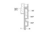
第2フレーム8は、図6、図7に示すように、第2枠部82、第2起立部81、凹部83,84、および外周縁部85を有している。
図8は、下方から見た光学装置50の断面図である。図9は、左方(−X方向)から見た光学装置50の断面図であり、光軸34Aの下側を示す図である。
第2枠部82は、図6に示すように、第1起立部71が挿通可能な挿通開口部821を有し、図8に示すように、第1枠部72に空間を介して対向するように形成されている。
また、第2枠部82には、図7に示すように、第1フレーム7側に突出する複数の突起82Pが形成されている。突起82Pは、流路6内に突出し、液体が衝突することにより乱流を発生させる機能を有している。突起82Pについては、後で詳細に説明する。As shown in FIGS. 6 and 7, the
FIG. 8 is a cross-sectional view of the
As shown in FIG. 6, the
Further, as shown in FIG. 7, the
第2起立部81は、図7に示すように、挿通開口部821の縁部から第1フレーム7側に起立して平面視矩形状に形成され、図8に示すように、第1起立部71の外周、すなわち、第1起立部71の開口部521とは反対側に積層されるように形成されている。 As shown in FIG. 7, the
凹部83は、第1フレーム7の凹部73に対向する位置に設けられ、第1フレーム7側が半円筒状に凹む形状を有している。そして、凹部83は、凹部73とで流入部51を形成する。
凹部84は、第1フレーム7の凹部74に対向する位置に設けられ、第1フレーム7側が半円筒状に凹む形状を有している。そして、凹部84は、凹部74とで流出部53を形成する。The
The
外周縁部85は、第2枠部82に対して第1フレーム7側に屈曲された部位であり、図6に示すように、凹部83,84の上側以外の外周の端部に形成されている。そして、外周縁部85には、図8、図9に示すように、第1枠部72に積層されるように平坦に形成された端部851が設けられている。端部851には、第1枠部72の2つの位置決め孔72hにそれぞれ対応する位置決め孔851hが形成されている。 The outer
第1フレーム7と第2フレーム8とは、位置決め孔72h,851hに治具が挿通されて互いに位置決めされ、第1枠部72と端部851との間、および第1起立部71と第2起立部81との間が、例えば、ロウ付け等によって接続される。そして、第1フレーム7と第2フレーム8とが接続されることによって、流入部51、流路形成部52、および流出部53を有する保持部5が形成される。そして、保持部5は、流入部51および流出部53の上側以外が密閉され、流路形成部52内には、流入部51および流出部53に連通する流路6が設けられる。流路6は、図8に示すように、第1枠部72と第2枠部82との間の第2起立部81の外側で、端部851の内側に環状に設けられている。このように、流路6は、第1フレーム7と第2フレーム8とが接合されることによって形成されている。 The
また、流路形成部52の厚み、すなわち、光軸34Aに沿う方向の大きさは、流入部51および流出部53の大きさ(外径寸法)より小さく形成されている。そして、保持部5は、図8に示すように、第1フレーム7の第1枠部72が光変調装置341に対向して配置される。光変調装置341は、防塵ガラス340Nが接着剤を介して第1枠部72に固定される。
流路6は、図8に示すように、光軸34Aに沿う方向から見て、一部が光変調装置341に重なるように設けられている。具体的に、流路6は、光変調装置341の端部からオーバーラップOLを有して設けられている。Further, the thickness of the flow
As shown in FIG. 8, the
ここで流路6について、図7を用いて詳細に説明する。
流路6は、図7に示すように、環状に配置された第1流路部61、第2流路部62、第3流路部63、および第4流路部64を有している。
第1流路部61は、開口部521の左方(−X方向)で、流入部51の下方に設けられ、下方に延出している。第2流路部62は、開口部521の上方に設けられ、流入部51の下方から右方(+X方向)に延出している。第3流路部63は、開口部521の下方に設けられ、第1流路部61の下方から右方(+X方向)に延出している。第4流路部64は、開口部521の右方(+X方向)に設けられ、第3流路部63の右方(+X方向)から上方に延出している。また、第2流路部62は、第4流路部64の上方に接続されている。下方は第1方向に相当し、右方は第2方向に相当する。Here, the
As shown in FIG. 7, the
The first
このように、流路6は、互いに対向して配置され、第1方向に延出する第1流路部61および第4流路部64と、互いに対向して配置され、第1方向に交差する第2方向に延出する第2流路部62および第3流路部63と、を有している。そして、第1流路部61、第2流路部62、第3流路部63、および第4流路部64は環状に接続されている。また、流路6は、光変調装置341の画像形成領域(光学有効領域)に対応して第2流路部62および第3流路部63が、第1流路部61および第4流路部64より長く形成されている。 In this way, the
前述した第2フレーム8に設けられた突起82Pは、図7に示すように、第2流路部62および第3流路部63内に突出してそれぞれ複数設けられている。第2流路部62に設けられた複数の突起82Pと、第3流路部63に設けられた複数の突起82Pとは上下において略対称に形成されている。ここでは、第3流路部63に設けられた突起82Pに注目して説明する。
図10は、光学装置50の部分断面図であり、図9におけるA部の拡大図である。図11は、第2フレーム8の部分平面図であり、第3流路部63の内部を示す図である。As shown in FIG. 7, a plurality of the
FIG. 10 is a partial cross-sectional view of the
突起82Pは、X方向(左右方向)の大きさと上下方向の大きさとの比が2以下(例えば、円柱状)に形成され、図10に示すように、第1フレーム7の第1枠部72に向かって突出し、第1枠部72から離間して形成されている。また、第2フレーム8は、プレス加工によって形成されているため、突起82Pの反対側の面に凹部が形成されている。なお、図2、図5、図6では、この凹部を省略している。
複数の突起82Pは、図11に示すように、第2起立部81寄りに併設された複数の第1突起82Pa、および複数の第1突起82Paより下側の外周縁部85寄りに設けられた複数の第2突起82Pbを有している。また、第2突起82Pbは、下方から見て、隣り合う第1突起82Paの間に位置するように配置されている。The
As shown in FIG. 11, the plurality of
次に、液冷装置4から送られた液体の流れについて説明する。
液冷装置4から送られた液体は、図7に示すように、流入部51から流路6を流通した後、流出部53から保持部5の外部、すなわち液冷装置4に流出する。具体的に、流入部51から流入された液体は、一部が第1流路部61で下方に分流され、残部が第2流路部62で下方に交差する右方(+X方向)に分流される。
そして、第1流路部61を流れた液体は、第3流路部63で方向が変更されて右方(+X方向)に流通する。第3流路部63を流れた液体は、第4流路部64で方向が変更されて上方に流通し、第2流路部62を流通した液体が合流する。第4流路部64を流れた液体は、流出部53から液冷装置4に流出する。Next, the flow of the liquid sent from the
As shown in FIG. 7, the liquid sent from the
Then, the liquid that has flowed through the first
また、第2流路部62および第3流路部63を流れる液体は、第2流路部62および第3流路部63に突起82Pが設けられているので、一部がこの突起82Pに衝突して方向が変更されるが全体として+X方向(第2方向)に流れる。ここで、流路6内を全体的に流れる液体の方向を流通方向とする。すなわち、第2流路部62および第3流路部63においては、+X方向(第2方向)が流通方向となる。 Further, since the liquid flowing through the second
第2流路部62および第3流路部63を流れる液体の一部は、突起82Pに衝突して乱流となって流れる。具体的に、第3流路部63内の液体の流れについて説明する。
図12は、第3流路部63内の一部を示す図であり、図11におけるB部の拡大図である。
突起82Pは、前述したように、また、図12に示すように、第2起立部81寄りに併設された複数の第1突起82Pa、および複数の第2突起82Pbを有している。そして、第2突起82Pbは、下方から見て、隣り合う第1突起82Paの間に位置するように配置されている。すなわち、第2突起82Pbは、この第2突起82Pbの上流側に位置する第1突起82Paに対し、第2起立部81とは反対側の斜め下流側に配置されている。また、第2突起82Pbの第2起立部81側の斜め下流側には、第1突起82Paが配置されている。A part of the liquid flowing through the second
12 is a view showing a part of the third
As described above, the
第1流路部61から第3流路部63に流れた液体の一部は、図12に示すように、第1突起82Paおよび第2突起82Pbに衝突して乱流となる。乱流は、主に第1突起82Pa、第2突起82Pbそれぞれの上側、下側から下流に向かって生じる。
第1突起82Paの上側から乱流となって流れる液体の一部は、第2起立部81に向かって流れる。また、第1突起82Paの下側から乱流となって流れる液体の一部は、斜め下流側に配置された第2突起82Pbに衝突し、第2起立部81に向かって流れる。
第2突起82Pbの上側から乱流となって流れる液体の一部は、この第2突起82Pbの斜め下流側に配置されている第1突起82Paに衝突して第2起立部81に向かって流れる。第2突起82Pbの下側から乱流となって流れる液体の一部は、外周縁部85に向かって流れる。As shown in FIG. 12, a part of the liquid that flows from the first
Part of the liquid that flows as a turbulent flow from the upper side of the
A part of the liquid that flows as a turbulent flow from the upper side of the second protrusion 82Pb collides with the first protrusion 82Pa disposed obliquely downstream of the second protrusion 82Pb and flows toward the
このように、突起82Pが設けられることによって、第3流路部63内に乱流が生じると共に、上述したように配置された突起82Pによって、多くの乱流が第2起立部81側に向かって流れる。その結果、第3流路部63の内壁(第2起立部81)に層流では生じる温度境界層の発生が効率よく抑制されるので、第2起立部81と液体との間で熱交換が良好に行われる。 As described above, the provision of the
第2流路部62においても第3流路部63と同様に、突起82Pによって乱流が生じ、第2起立部81と液体との間で熱交換が良好に行われる。
なお、突起82Pの形状は、流通方向の大きさと、流通方向に交差する方向(交差方向)の大きさとの比が2以下であれば、円柱状に限らず、例えば、平面視楕円状や平面視多角形状であってもよい。Similarly to the third
The shape of the
このように、流入部51から流入された液体は、第1流路部61、第3流路部63、および第4流路部64を辿って流れる第1経路60Aと、第2流路部62を辿って第4流路部64に合流する第2経路60Bと、を経て流出部53から液冷装置4に流出する。 Thus, the liquid that has flowed in from the
光変調装置341は、流路6を流通する液体によって冷却される。具体的に、入射する光によって発熱する光変調装置341の熱は、第1フレーム7を介して液体に伝達される。また、流路6が光変調装置341の周縁に沿って環状に構成されているので、光変調装置341の熱は、光変調装置341の光学有効領域(画像形成領域)を囲む領域から液体に伝わる。また、第2起立部81は、光学有効領域の近傍に配置され、第2流路部62および第3流路部63における第2起立部81は、前述したように、突起82Pによる乱流によって液体との間で熱交換が良好に行われる。すなわち、光変調装置341は、最も高温となる中央に近い位置が効率よく冷却される。 The
そして、直列に配置された保持部5R,5G,5Bから流出した液体は、循環流路4Fを辿って熱交換装置43に流入する。熱交換装置43に流入した液体は、熱交換装置43にて熱が吸収されて冷却される。そして、熱交換装置43にて冷却された液体は、再び、保持部5(本実施形態では、保持部5R)に流入し、光変調装置341を冷却する。熱交換装置43で吸収された熱は、前述したように、熱交換装置43の放熱部433から放熱される。そして、放熱部433から放熱された熱は、図示しない排気装置によって外装筐体2の排気口からプロジェクター1の外部に排出される。 And the liquid which flowed out from holding |
また、保持部5が光変調装置341の光入射側に配置されているので、光学装置50に向かう光の一部(光変調装置341の光学有効領域の外側に向かう漏れ光等)は、保持部5にも照射されるが、流路6が光変調装置341の端部からオーバーラップOL(図8参照)を有して設けられているので、照射された光によって発熱する保持部5の熱が光変調装置341に伝わりにくくなる。すなわち、保持部5の光が照射された被照射部(主に、第2フレーム8の第2枠部82)と光変調装置341との間に、液体が介在しているので、照射された光によって発熱する被照射部の熱が光変調装置341に伝わりにくくなる。
このように、光変調装置341は、環状の流路6を有する保持部5に保持され、流路6に供給された液体によって冷却される。In addition, since the holding
Thus, the
以上説明したように、本実施形態によれば、以下の効果を得ることができる。
(1)光変調装置341を保持する保持部5には、環状の流路6が設けられ、光変調装置341の光学有効領域を囲む領域から光変調装置341の熱を液体に伝えることが可能となる。さらに、流路6内には突起82Pが形成され、乱流が発生することにより流路6の内壁(第2起立部81)と液体との間の熱交換を良好に行わせることが可能となる。
また、保持部5とは異なる部材(パイプ状の部材)を用いて液体を流通させる構成に比べ、光変調装置341と液体との間に介在する部材が減るので、光変調装置341の熱は、効率よく液体に伝わる。
よって、光変調装置341の効率的な冷却が可能となり、光変調装置341の温度上昇が効率よく抑えられる。したがって、光変調装置341の劣化が抑制され、光変調装置341が有する光学特性を確実に発揮できる光学装置50の提供が可能となる。
また、保持部5とは異なる部材を用いて液体を流通させる構成に比べて少ない部品点数で構成できるので、製造工数や部品コストの低減、および小型化が可能な光学装置50の提供が可能となる。As described above, according to the present embodiment, the following effects can be obtained.
(1) The holding
In addition, since the number of members interposed between the
Therefore, the
In addition, since the number of components can be reduced compared to the configuration in which the liquid is circulated using a member different from the holding
(2)流路6は、第1流路部61〜第4流路部64を有し、環状に形成されている。これによって、矩形状の光学有効領域(画像形成領域)を有する光変調装置341に対し、この光学有効領域に近づけて流路6を設けることが可能となる。よって、光変調装置341の熱をさらに効率よく液体に伝えることが可能となるので、光変調装置341の温度上昇をさらに抑制可能な光学装置50の提供が可能となる。 (2) The
(3)突起82Pは、平面視矩形状の流路6における長手方向となる第2流路部62および第3流路部63に設けられている。これによって、層流では第1流路部61や第4流路部64より広い範囲に生じやすい第2流路部62や第3流路部63における温度境界層の発生を抑えることが可能となる。よって、長方形状の光学有効領域を有する光変調装置341を備え、この光変調装置341の温度上昇が効率よく抑制される光学装置50の提供が可能となる。 (3) The
(4)保持部5は、第1フレーム7と、突起82Pが設けられた第2フレーム8とが接合されることにより流路6が形成されている。これによって、内部に液体が流通する流路6を有する構成であっても、容易な加工で、また、製造工数の増加を抑制して突起82Pを有する保持部5を形成することができる。 (4) In the holding
(5)環状の流路形成部52の内周縁の側は、板状の第1起立部71に板状の第2起立部81が接続されて形成されている。そして、流路6は、この第2起立部81の外側に設けられている。これによって、光変調装置341の光学有効領域に近づけて流路6を形成することが可能となる。よって、2つの部材(第1フレーム7、第2フレーム8)で保持部5を形成する構成であっても、容易に流路6を形成しつつ、光変調装置341が効率よく冷却される光学装置50の提供が可能となる。 (5) The inner peripheral edge side of the annular flow
(6)保持部5は、流入部51および流出部53が流路形成部52に対して同一側に配置されているので、流入部51および流出部53に接続される管状部材44をコンパクトに配置することが可能となる。よって、プロジェクター1の小型に寄与できる光学装置50の提供が可能となる。 (6) Since the
(7)光学素子としての光変調装置341は、保持部5に流入された液体によって効率よく冷却されるので、温度上昇が抑制される。よって、長期に亘って自身が有する光学特性を発揮して入射した光を変調する光変調装置341を備えた光学装置50の提供が可能となる。 (7) Since the
(8)プロジェクター1は、光学装置50および液冷装置4を備えているので、高輝度の光を射出する光源311を備える構成であっても、光変調装置341が効率よく冷却され、長期に亘って明るい画像や画質が良好な画像の投写が可能となる。
また、保持部5とは異なる部材を用いて液体を流通させる構成に比べ、流路6の形状の自由度を高めることができるので、低い圧力で液体を循環させることが可能となる。これによって、液体を循環させるための液体圧送部41の小型化や低パワー化が可能となる。
また、低い圧力で液体を循環させることが可能なので、循環流路4Fにおける各部材間の接続部から液体の揮発や漏れを防止することが可能となる。これによって、プロジェクター1内の他の部材への液体の付着を防止できると共に、備える液体の量を少なく構成することが可能となる。よって、小型、低消費電力の液冷装置4を備えたプロジェクター1の提供が可能となる。(8) Since the projector 1 includes the
Moreover, since the freedom degree of the shape of the
Further, since the liquid can be circulated at a low pressure, it is possible to prevent the liquid from volatilizing or leaking from the connection portion between the members in the
なお、本発明は上述した実施形態に限定されず、上述した実施形態に種々の変更や改良などを加えることが可能である。変形例を以下に述べる。 Note that the present invention is not limited to the above-described embodiment, and various modifications and improvements can be added to the above-described embodiment. A modification will be described below.
(変形例1)
前記実施形態では、流路6内に突起82Pが設けられているが、流入部51の内部に突起が設けられる構成であってもよい。また、保持部5を構成する2つの部材を位置合わせするために、この突起を利用する構成も可能である。
図13、図14は、変形例1の保持部15の構成を説明するための模式図である。具体的に、図13は、保持部15の一部を示す平面図であり、図14は、保持部15の一部を示す断面図である。(Modification 1)
In the embodiment, the
FIGS. 13 and 14 are schematic views for explaining the configuration of the holding
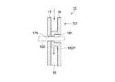
保持部15は、図13、図14に示すように、熱伝導性材料で形成された第1フレーム17および第2フレーム18を備え、この第1フレーム17と第2フレーム18とが接合されて構成されている。保持部15は、前記実施形態の保持部5と同様に、流入部151、内部に流路16を有する流路形成部152、および流出部(図示省略)を有している。そして、流入部151の内部には、突起182Pが設けられている。
突起182Pは、図14に示すように、第2フレーム18から円柱状に突出し、熱伝導可能に第1フレーム17に接続されている。また、突起182Pの中央、および第1フレーム17には、ピン状の部材100が挿通される挿通孔(第1フレーム17の挿通孔を17h、第2フレーム18の挿通孔を18hとする)が形成されている。As shown in FIGS. 13 and 14, the holding
As shown in FIG. 14, the
第1フレーム17と第2フレーム18とは、挿通孔17h,18hに部材100が挿通されて互いに位置決めされ、前記実施形態で示した個所に加え、突起182Pの先端がロウ付け等によって接続される。第2フレーム18から突出する突起182Pは、第1フレーム17に熱伝導可能に接続され、伝熱用突起に相当する。 The
流入部151に流入した液体の一部は、突起182Pに衝突して乱流として流路16内を流通し、光変調装置341を冷却する。また、光変調装置341から第1フレーム17に伝わった熱は、突起182Pを含め、ロウ付けされた個所を介して第2フレーム18に伝わる。
このように、突起182Pは、流入部151の内部に設けられ、乱流を発生させると共に、第1フレーム17と第2フレーム18との位置合わせ、および保持部15による放熱性を向上させる機能を有している。
また、流路内および流入部の内部に突起が設けられる保持部を構成してもよい。Part of the liquid that has flowed into the
As described above, the
Moreover, you may comprise the holding | maintenance part in which a protrusion is provided in a flow path and the inside of an inflow part.
(変形例2)
変形例1における突起182Pに替えて第1フレーム17や第2フレーム18とは異なる部材で突起を構成してもよい。
図15は、変形例2の保持部25の構成を説明するための模式図であり、保持部25の一部を示す平面図である。
保持部25は、図15に示すように、第1フレーム(図示省略)および第2フレーム28を備え、この第1フレームと第2フレーム28とが接合されて構成されている。保持部25は、前記実施形態の保持部5と同様に、流入部251、内部に流路26を有する流路形成部252、および流出部(図示省略)を有している。そして、流入部251の内部には、突起282Pが設けられている。
突起282Pは、例えばコイルバネで構成され、液体が流入部251に流入される方向に中心軸が沿うように配置されている。
流入部251に流入した液体の一部は、突起282Pに衝突して乱流として流路26内を流通し、光変調装置341を冷却する。(Modification 2)
Instead of the
FIG. 15 is a schematic diagram for explaining the configuration of the holding
As shown in FIG. 15, the holding
The
Part of the liquid that has flowed into the
(変形例3)
前記実施形態の突起82Pは、第1フレーム7から離間している(図10参照)が、第1フレーム7に熱伝導可能に当接する突起を有するように構成してもよい。
図16は、変形例3の保持部305の構成を説明するための模式図であり、保持部305および保持部305に保持された光変調装置341の部分断面図である。
保持部305は、図16に示すように、前記実施形態の第1フレーム7と、前記実施形態の第2フレーム8とは異なる第2フレーム38が接合されて構成されている。そして、第2フレーム38には、第1フレーム7に熱伝導可能に当接する突起382Pが形成されている。突起382Pは、伝熱用突起に相当する。
この構成によれば、突起382Pによって、第1フレーム7から第2フレーム38への熱伝導性が向上するので、保持部305による放熱性の向上が可能となる。(Modification 3)
Although the
FIG. 16 is a schematic diagram for explaining the configuration of the holding
As shown in FIG. 16, the holding
According to this configuration, since the thermal conductivity from the
また、保持部305が光変調装置341の光入射側に配置される構成においては、保持部305の光が照射された被照射部(第2フレーム38)と光変調装置341との間に、液体が介在していることが望ましいので、光軸34Aに沿う方向から見て、突起382Pが光変調装置341に重ならない位置に設けることが望ましい。すなわち、図16に示す二点鎖線で示した突起382Pが設けられないように構成することが望ましい。 In the configuration in which the
(変形例4)
前記実施形態の突起82Pは、第2流路部62および第3流路部63に設けられているが、第2流路部62および第3流路部63のいずれか一方に設けてもよい。
また、第1流路部61や第4流路部64、あるいは、流路6の角部(例えば、第1流路部61と第3流路部63との間や、第3流路部63と第4流路部64との間)に突起82Pを設けてもよい。(Modification 4)
The
Further, the first
(変形例5)
前記実施形態の突起82Pは、流通方向の大きさと交差方向の大きさとの比が2以下で形成されているが、交差方向の大きさに対する流通方向の大きさの比が2を超えて流通方向に延出する形状であってもよい。例えば、ヒートシンクにおけるフィンに相当する形状等を突起として形成してもよい。この構成の場合、流路内の保持部の表面積をより大きくすることができるので、保持部による放熱性の向上が可能となる。
また、流通方向の大きさと交差方向の大きさとの比が2以下の突起、および交差方向の大きさに対する流通方向の大きさの比が2を超える大きさの突起の双方を備える構成であってもよい。(Modification 5)
The
The ratio of the size in the distribution direction to the size in the cross direction is 2 or less, and the protrusion has a size in which the ratio of the size in the distribution direction to the size in the cross direction exceeds 2. Also good.
(変形例6)
前記実施形態の突起82Pは、第2フレーム8に設けられているが、第1フレーム7に設けられる構成であってもよい。同様に、変形例1、変形例3の突起182P,382Pが第1フレーム17,7に設けられる構成であってもよい。(Modification 6)
The
(変形例7)
前記実施形態、変形例3では、液体が流通する保持部5,305に保持される光学素子として光変調装置341が構成されているが、光変調装置341に限らず、他の光学部品をこの光学素子として構成してもよい。この光学素子としては、例えば、入射側偏光板342や射出側偏光板343を例示することができる。また、光学ユニット3が位相差板や光の位相差を補償する補償素子等を備える構成とし、これらの位相差板や補償素子等を光学素子として構成してもよい。(Modification 7)
In the embodiment and the third modification, the
(変形例8)
前記実施形態の保持部5は、光変調装置341の光入射側に配置されているが、光変調装置341の光射出側に配置された構成であってもよい。また、光変調装置341の両側(光入射側および光射出側)に保持部5が設けられる構成であってもよい。同様に、変形例1〜3の保持部15,25,305が光変調装置341の光入射側、光射出側のいずれか一方に配置された構成でも、光変調装置341の両側に配置された構成であってもよい。(Modification 8)
The holding
(変形例9)
前記実施形態の保持部5は、流路形成部52に対し、流入部51および流出部53が同一側に配置されているが、流入部51および流出部53の位置は、この位置に限定されるものではない。例えば、流出部53が流路形成部52に対し、流入部51の対角となる位置に設けられる構成であってもよい。(Modification 9)
In the holding
(変形例10)
前記実施形態の第1フレーム7、第2フレーム8は、板金からプレス加工によって形成されているが、溶融された金属を金型で成型する成型加工によって形成してもよい。この成型加工を用いれば、突起82Pの反対側の面に凹部(図10参照)を有さずに保持部5を構成することができる。同様に、変形例1〜3の保持部15,25,305を構成する2つの部材は、板金からプレス加工によって形成されるものであっても、成型加工によって形成されるものであってもよい。(Modification 10)
The
(変形例11)
前記実施形態の保持部5は、2つの部材(第1フレーム7、第2フレーム8)が組み合わされて構成されているが、金属粉等を用い、3Dプリンター等の立体物造形装置によって1つの部材で保持部を構成してもよい。この構成の場合、流路形成部の内周縁を形成する肉厚を前記実施形態における肉厚(第1起立部71および第2起立部81の厚み)より薄く形成可能なので、流路を光学有効領域にさらに近づけることが可能となる。また、前記実施形態における端部851が不要となるので、さらに小型の保持部が可能となる。同様に、変形例1〜3の保持部15,25,305が1つの部材で構成される態様であってもよい。(Modification 11)
The holding
(変形例12)
前記実施形態の光変調装置341(光学素子)は、接着剤を用いて保持部5に保持されているが、この構成に限らない。例えば、光学素子の保持部5とは反対側に配置された押え部材を備え、保持部5とこの押え部材とで光学素子を挟持することによって光学素子を保持する構成であってもよい。(Modification 12)
The light modulation device 341 (optical element) of the embodiment is held by the holding
(変形例13)
前記実施形態の液冷装置4は、タンク42を備えているが、タンク42を備えない構成も可能である。(Modification 13)
Although the
(変形例14)
前記実施形態の光源装置31は、放電型の光源311を有して構成されているが、放電型に限らず、その他の方式のランプや、発光ダイオードやレーザー等の固体光源等を備える構成であってもよい。
また、前記実施形態の光学ユニット3は、図1に示すように、光源装置31が光を射出する方向と、投写光学装置35が投写する方向とが同一方向になるように構成されているが、光源装置31が光を射出する方向と、投写光学装置35が投写する方向とが異なる方向となるように構成してもよい。(Modification 14)
The
Further, as shown in FIG. 1, the
(変形例15)
前記実施形態のプロジェクター1は、R光、G光、およびB光に対応する3つの光変調装置341R,341G,341Bを備えた、いわゆる3板方式を採用しているが、これに限らず、単板方式を採用してもよく、あるいは、2つまたは4つ以上の光変調装置341を備える構成であってもよい。
また、前記実施形態の光変調装置341は、透過型の液晶パネル340を有して構成されているが、反射型の液晶パネルで構成された態様であってもよい。また、光変調装置としてマイクロミラー型の光変調装置、例えば、DMD(Digital Micromirror Device)等を利用したものであってもよい。(Modification 15)
The projector 1 according to the embodiment employs a so-called three-plate method including three
In addition, the
1…プロジェクター、4…液冷装置、5,5R,5G,5B,15,25,305…保持部、6,16,26…流路、7,17…第1フレーム、8,18,28,38…第2フレーム、34A…光軸、35…投写光学装置、50…光学装置、51,151,251…流入部、52,152,252…流路形成部、53…流出部、61…第1流路部、62…第2流路部、63…第3流路部、64…第4流路部、82P,282P…突起、182P,382P…突起(伝熱用突起)、311…光源、341,341R,341G,341B…光変調装置(光学素子)。 DESCRIPTION OF SYMBOLS 1 ... Projector, 4 ... Liquid cooling device, 5, 5R, 5G, 5B, 15, 25, 305 ... Holding part, 6, 16, 26 ... Flow path, 7, 17 ... 1st frame, 8, 18, 28, 38 ... 2nd frame, 34A ... optical axis, 35 ... projection optical device, 50 ... optical device, 51, 151, 251 ... inflow part, 52, 152, 252 ... flow path forming part, 53 ... outflow part, 61 ... first 1 channel part, 62 ... 2nd channel part, 63 ... 3rd channel part, 64 ... 4th channel part, 82P, 282P ... projection, 182P, 382P ... projection (projection for heat transfer), 311 ... light source , 341, 341R, 341G, 341B... Light modulator (optical element).
Claims (8)
Translated fromJapanese前記保持部は、
当該保持部の外部から供給された液体が流入する流入部と、
前記光学素子の周縁に沿って環状に配設され、内部に前記流入部からの前記液体が流通する流路を有する流路形成部と、
前記流路を流れた前記液体を当該保持部の外部に流出させるための流出部と、
を備え、
前記流入部の内部および前記流路内の少なくともいずれか一方には、突起が設けられていることを特徴とする光学装置。An optical device comprising: an optical element disposed on an optical axis of incident light; and a holding unit that holds the optical element,
The holding part is
An inflow part into which the liquid supplied from the outside of the holding part flows, and
A flow path forming section that is annularly disposed along the periphery of the optical element and has a flow path through which the liquid from the inflow section flows;
An outflow part for allowing the liquid flowing through the flow path to flow out of the holding unit;
With
A projection is provided in at least one of the inside of the inflow portion and the flow path.
前記突起は、前記液体が前記流路内を流通する流通方向の大きさと、前記流通方向に交差する方向の大きさとの比が2以下であることを特徴とする光学装置。The optical device according to claim 1,
The optical device according to claim 1, wherein a ratio of a size in a flow direction in which the liquid flows in the flow path and a size in a direction intersecting the flow direction is 2 or less.
前記流路は、
互いに対向して配置され、第1方向に延出する第1流路部および第4流路部と、
互いに対向して配置され、前記第1方向に交差する第2方向に延出する第2流路部および第3流路部と、
を有し、
前記第1流路部、前記第2流路部、前記第3流路部、および前記第4流路部は環状に接続され、
前記突起は、前記流路内に設けられていることを特徴とする光学装置。The optical device according to claim 2,
The flow path is
A first flow path section and a fourth flow path section that are arranged to face each other and extend in the first direction;
A second flow path portion and a third flow path portion, which are arranged to face each other and extend in a second direction intersecting the first direction;
Have
The first flow path part, the second flow path part, the third flow path part, and the fourth flow path part are connected in an annular shape,
The optical device, wherein the protrusion is provided in the flow path.
前記第2流路部および前記第3流路部は、前記第1流路部および前記第4流路部より長く形成され、
前記突起は、前記第2流路部および前記第3流路部の少なくともいずれか一方に設けられていることを特徴とする光学装置。The optical device according to claim 3,
The second flow path part and the third flow path part are formed longer than the first flow path part and the fourth flow path part,
The optical device according to claim 1, wherein the protrusion is provided on at least one of the second flow path portion and the third flow path portion.
前記保持部は、
前記光軸に沿う方向において互いに対向して配置され、互いが接合されることにより前記流路を形成する第1フレームおよび第2フレームを備え、
前記突起は、前記第1フレームおよび前記第2フレームの一方から突出していることを特徴とする光学装置。An optical device according to any one of claims 1 to 4, wherein
The holding part is
A first frame and a second frame which are arranged to face each other in a direction along the optical axis and form the flow path by being joined to each other;
The optical device, wherein the protrusion protrudes from one of the first frame and the second frame.
前記第1フレームおよび前記第2フレームは、熱伝導性材料で形成され、
前記突起は、前記第1フレームおよび前記第2フレームの他方に熱伝導可能に当接または接続された伝熱用突起を有していることを特徴とする光学装置。The optical device according to claim 5,
The first frame and the second frame are formed of a heat conductive material,
2. The optical apparatus according to claim 1, wherein the protrusion has a heat transfer protrusion that is in contact with or connected to the other of the first frame and the second frame so as to allow heat conduction.
前記光学素子は、入射する光を変調する光変調装置であることを特徴とする光学装置。The optical device according to any one of claims 1 to 6,
The optical device is an optical modulation device that modulates incident light.
前記光源から射出された光が入射する請求項1〜請求項7のいずれか一項に記載の光学装置と、
前記光学装置から射出された光に応じた画像を投写する投写光学装置と、
前記光学装置に液体を循環させる液冷装置と、
を備えることを特徴とするプロジェクター。A light source that emits light;
The optical device according to any one of claims 1 to 7, wherein light emitted from the light source is incident;
A projection optical device that projects an image according to light emitted from the optical device;
A liquid cooling device for circulating a liquid in the optical device;
A projector comprising:
Priority Applications (4)
| Application Number | Priority Date | Filing Date | Title |
|---|---|---|---|
| JP2016228640AJP2018084726A (en) | 2016-11-25 | 2016-11-25 | Optical device and projector |
| CN201711112541.3ACN108107656B (en) | 2016-11-25 | 2017-11-13 | Optical devices and projectors |
| US15/815,286US10372025B2 (en) | 2016-11-25 | 2017-11-16 | Optical device and projector |
| US16/289,128US10634978B2 (en) | 2016-11-25 | 2019-02-28 | Optical device and projector |
Applications Claiming Priority (1)
| Application Number | Priority Date | Filing Date | Title |
|---|---|---|---|
| JP2016228640AJP2018084726A (en) | 2016-11-25 | 2016-11-25 | Optical device and projector |
Publications (2)
| Publication Number | Publication Date |
|---|---|
| JP2018084726Atrue JP2018084726A (en) | 2018-05-31 |
| JP2018084726A5 JP2018084726A5 (en) | 2019-10-31 |
Family
ID=62237163
Family Applications (1)
| Application Number | Title | Priority Date | Filing Date |
|---|---|---|---|
| JP2016228640AWithdrawnJP2018084726A (en) | 2016-11-25 | 2016-11-25 | Optical device and projector |
Country Status (1)
| Country | Link |
|---|---|
| JP (1) | JP2018084726A (en) |
Cited By (1)
| Publication number | Priority date | Publication date | Assignee | Title |
|---|---|---|---|---|
| WO2022030166A1 (en)* | 2020-08-06 | 2022-02-10 | パナソニックIpマネジメント株式会社 | Projection-type image display device |
Citations (11)
| Publication number | Priority date | Publication date | Assignee | Title |
|---|---|---|---|---|
| US5537303A (en)* | 1991-04-30 | 1996-07-16 | Vari-Lite, Inc. | Programmable rotatable gobo system |
| JPH10319381A (en)* | 1997-05-20 | 1998-12-04 | Matsushita Electric Ind Co Ltd | Light valve device, manufacturing method thereof, and liquid crystal projection device using light valve device |
| JP2004012934A (en)* | 2002-06-07 | 2004-01-15 | Seiko Epson Corp | Display panel laminate, case, display panel module, projection display device, and method of cooling display panel module |
| JP2004117580A (en)* | 2002-09-24 | 2004-04-15 | Seiko Epson Corp | Electro-optical device, electronic device, and projection display device |
| JP2005010630A (en)* | 2003-06-20 | 2005-01-13 | Hitachi Ltd | LCD projector |
| JP2005275296A (en)* | 2004-03-26 | 2005-10-06 | Seiko Epson Corp | Light modulation element holder, optical device, and projector |
| JP2005275189A (en)* | 2004-03-26 | 2005-10-06 | Hitachi Ltd | Liquid crystal display device and liquid crystal cooling unit |
| JP2005284138A (en)* | 2004-03-30 | 2005-10-13 | Seiko Epson Corp | Optical apparatus and projector |
| JP2008103623A (en)* | 2006-10-20 | 2008-05-01 | Denso Corp | Semiconductor device |
| JP2011103369A (en)* | 2009-11-11 | 2011-05-26 | Nippon Inter Electronics Corp | Power semiconductor module and method of manufacturing the same |
| WO2012114475A1 (en)* | 2011-02-23 | 2012-08-30 | トヨタ自動車株式会社 | Cooling device |
- 2016
- 2016-11-25JPJP2016228640Apatent/JP2018084726A/ennot_activeWithdrawn
Patent Citations (11)
| Publication number | Priority date | Publication date | Assignee | Title |
|---|---|---|---|---|
| US5537303A (en)* | 1991-04-30 | 1996-07-16 | Vari-Lite, Inc. | Programmable rotatable gobo system |
| JPH10319381A (en)* | 1997-05-20 | 1998-12-04 | Matsushita Electric Ind Co Ltd | Light valve device, manufacturing method thereof, and liquid crystal projection device using light valve device |
| JP2004012934A (en)* | 2002-06-07 | 2004-01-15 | Seiko Epson Corp | Display panel laminate, case, display panel module, projection display device, and method of cooling display panel module |
| JP2004117580A (en)* | 2002-09-24 | 2004-04-15 | Seiko Epson Corp | Electro-optical device, electronic device, and projection display device |
| JP2005010630A (en)* | 2003-06-20 | 2005-01-13 | Hitachi Ltd | LCD projector |
| JP2005275296A (en)* | 2004-03-26 | 2005-10-06 | Seiko Epson Corp | Light modulation element holder, optical device, and projector |
| JP2005275189A (en)* | 2004-03-26 | 2005-10-06 | Hitachi Ltd | Liquid crystal display device and liquid crystal cooling unit |
| JP2005284138A (en)* | 2004-03-30 | 2005-10-13 | Seiko Epson Corp | Optical apparatus and projector |
| JP2008103623A (en)* | 2006-10-20 | 2008-05-01 | Denso Corp | Semiconductor device |
| JP2011103369A (en)* | 2009-11-11 | 2011-05-26 | Nippon Inter Electronics Corp | Power semiconductor module and method of manufacturing the same |
| WO2012114475A1 (en)* | 2011-02-23 | 2012-08-30 | トヨタ自動車株式会社 | Cooling device |
Cited By (4)
| Publication number | Priority date | Publication date | Assignee | Title |
|---|---|---|---|---|
| WO2022030166A1 (en)* | 2020-08-06 | 2022-02-10 | パナソニックIpマネジメント株式会社 | Projection-type image display device |
| JP2022030034A (en)* | 2020-08-06 | 2022-02-18 | パナソニックIpマネジメント株式会社 | Projection type image display apparatus |
| EP4194945A4 (en)* | 2020-08-06 | 2024-01-31 | Panasonic Intellectual Property Management Co., Ltd. | PROJECTION TYPE IMAGE DISPLAY DEVICE |
| JP7570025B2 (en) | 2020-08-06 | 2024-10-21 | パナソニックIpマネジメント株式会社 | Projection type image display device |
Similar Documents
| Publication | Publication Date | Title |
|---|---|---|
| CN108107656B (en) | Optical devices and projectors | |
| US7556383B2 (en) | Projection display apparatus using liquid cooling and air cooling | |
| CN100592197C (en) | Optical device and projector | |
| TWI257522B (en) | Optical device and projector | |
| CN106054506B (en) | Heat-exchange device, cooling device and projecting apparatus | |
| CN204287712U (en) | Projector | |
| CN100520568C (en) | Optical device and projector | |
| US7150543B2 (en) | Optical modulator holder, optical device, and projector | |
| CN101546105A (en) | Projector | |
| JP6515647B2 (en) | projector | |
| JPWO2005064397A1 (en) | Optical device and projector | |
| US8348433B2 (en) | Liquid-cooling device including liquid pumping unit and liquid storage unit and projector including liquid-cooling device | |
| JP4096897B2 (en) | OPTICAL DEVICE, OPTICAL DEVICE MANUFACTURING METHOD, AND PROJECTOR | |
| JP4816799B2 (en) | projector | |
| JP4860663B2 (en) | Liquid crystal unit cooling method | |
| JP2018084726A (en) | Optical device and projector | |
| JP6805751B2 (en) | Optics and projectors | |
| JP6885034B2 (en) | Optics and projectors | |
| JP2007041414A (en) | Electronics | |
| JP3669365B2 (en) | Optical device and projector provided with the optical device | |
| JP2007041413A (en) | Light modulation element holder, optical device, and projector | |
| JP2005114994A (en) | Optical device and rear projector | |
| JP2005208632A (en) | Light modulation element holder, optical device, and projector | |
| JP2013182145A (en) | Projector | |
| JP2006126456A (en) | Light modulation element holder, optical device, and projector |
Legal Events
| Date | Code | Title | Description |
|---|---|---|---|
| RD05 | Notification of revocation of power of attorney | Free format text:JAPANESE INTERMEDIATE CODE: A7425 Effective date:20180910 | |
| RD03 | Notification of appointment of power of attorney | Free format text:JAPANESE INTERMEDIATE CODE: A7423 Effective date:20190402 | |
| A521 | Request for written amendment filed | Free format text:JAPANESE INTERMEDIATE CODE: A523 Effective date:20190919 | |
| A621 | Written request for application examination | Free format text:JAPANESE INTERMEDIATE CODE: A621 Effective date:20190919 | |
| RD07 | Notification of extinguishment of power of attorney | Free format text:JAPANESE INTERMEDIATE CODE: A7427 Effective date:20200803 | |
| A977 | Report on retrieval | Free format text:JAPANESE INTERMEDIATE CODE: A971007 Effective date:20200929 | |
| A131 | Notification of reasons for refusal | Free format text:JAPANESE INTERMEDIATE CODE: A131 Effective date:20201006 | |
| A521 | Request for written amendment filed | Free format text:JAPANESE INTERMEDIATE CODE: A523 Effective date:20201126 | |
| A131 | Notification of reasons for refusal | Free format text:JAPANESE INTERMEDIATE CODE: A131 Effective date:20210413 | |
| A761 | Written withdrawal of application | Free format text:JAPANESE INTERMEDIATE CODE: A761 Effective date:20210614 |