JP2018081564A - Input apparatus - Google Patents
Input apparatusDownload PDFInfo
- Publication number
- JP2018081564A JP2018081564AJP2016224253AJP2016224253AJP2018081564AJP 2018081564 AJP2018081564 AJP 2018081564AJP 2016224253 AJP2016224253 AJP 2016224253AJP 2016224253 AJP2016224253 AJP 2016224253AJP 2018081564 AJP2018081564 AJP 2018081564A
- Authority
- JP
- Japan
- Prior art keywords
- unit
- input
- locus
- input operation
- trajectory
- Prior art date
- Legal status (The legal status is an assumption and is not a legal conclusion. Google has not performed a legal analysis and makes no representation as to the accuracy of the status listed.)
- Granted
Links
- 210000003813thumbAnatomy0.000claimsabstractdescription18
- 238000000605extractionMethods0.000claimsdescription26
- 230000008859changeEffects0.000claimsdescription13
- 238000001514detection methodMethods0.000description16
- 238000000034methodMethods0.000description7
- 230000008569processEffects0.000description7
- 230000005540biological transmissionEffects0.000description6
- 239000000284extractSubstances0.000description6
- 238000013459approachMethods0.000description5
- 210000003811fingerAnatomy0.000description2
- 102100034112Alkyldihydroxyacetonephosphate synthase, peroxisomalHuman genes0.000description1
- 101000799143Homo sapiens Alkyldihydroxyacetonephosphate synthase, peroxisomalProteins0.000description1
- 230000009471actionEffects0.000description1
- 238000000848angular dependent Auger electron spectroscopyMethods0.000description1
- 238000010586diagramMethods0.000description1
- 230000000694effectsEffects0.000description1
- 210000004936left thumbAnatomy0.000description1
- 239000004973liquid crystal related substanceSubstances0.000description1
- 230000004044responseEffects0.000description1
Images


Landscapes
- Position Input By Displaying (AREA)
- User Interface Of Digital Computer (AREA)
Abstract
Description
Translated fromJapanese本発明は、車両に搭載される機器に対して入力操作を行うための入力装置に関するものである。 The present invention relates to an input device for performing an input operation on a device mounted on a vehicle.
従来の入力装置として、例えば特許文献1、2に記載されたものが知られている。特許文献1、2の入力装置は、表示部と、表示部から離れて、例えば、車両のセンターコンソールの上面に設けられた操作部とを備えている。操作部は、2次元平面上をスライド(移動)可能に設けられた可動部を有している。ユーザは、可動部をスライド操作することで、表示部に表示されるアイコン等に対する画面操作が可能となり、所定の車両機器に対する入力操作が行えるようになっている。尚、ユーザが可動部を操作する際には、ユーザの手(指)に操作反力が与えられるようになっている。 As conventional input devices, for example, those described in
また、特許文献3では、電子機器の動作を規定する複数のパラメータ項目の値を設定するためのパラメータ設定装置が記載されている。特許文献3では、ユーザは、複数のパラメータ値を一つの組みとしたパラメータセットを予め、複数設定してROMに記憶する。そして、ユーザは、入力操作ノブを回転操作することによって複数のパラメータセットの中から特定のパラメータセットに対応する複数のパラメータ値を一括で設定できるようになっている。更に、ユーザは、入力操作ノブを回転操作することで、複数のパラメータ値のうち、2つ以上のパラメータ値を同時に連動させて変更することができるようになっている。 Further,
ここで、特許文献1、2に記載された入力装置を車両のステアリングに搭載すると、ステアリングを握ったまま親指で入力操作することが可能となり、ステアリングから手を離さずに入力操作ができ、より安全な操作が可能となる。 Here, when the input device described in
ただし、一人ひとりのユーザにおいては、それぞれ、手の大きさによって親指の可動範囲が異なるので、親指による実際の入力操作軌跡が、狙うべき理想の位置(理想の操作軌跡)に対してずれてしまう場合がある。よって、このずれを低減できるように個人の手の大きさに合せて、操作感にかかるパラメータを個人別に変更可能とすることが望まれる。 However, in each individual user, the movable range of the thumb differs depending on the size of the hand, so that the actual input operation locus by the thumb is deviated from the ideal position to be aimed (ideal operation locus). There is. Therefore, it is desirable to be able to change the parameter relating to the operational feeling for each individual in accordance with the size of the individual hand so as to reduce this deviation.
しかしながら、上記特許文献3のようなパラメータ設定装置を用いた場合では、予め、複数(多数)のパラメータセットを作成して、装置自体に記憶させておく必要があり、事前の準備に手間がかかる。また、パラメータの設定を変更したい場合は、ユーザがその都度、ノブ操作(設定変更操作)する必要があり、同様に手間のかかるものとなる。 However, in the case of using the parameter setting device as in
このような手間のかかるものにおいては、ユーザは、例えば、パラメータの設定変更ができることを把握していても面倒な設定をせずに現状のまま使用し続ける、あるいは不慣れな設定のため設定行為を完了できない、あるいは最適な設定ができない、といった状況に陥る場合がある。 In such troublesome work, the user, for example, keeps using the current state without troublesome settings even if he / she knows that the parameter setting can be changed, or performs the setting action for an unfamiliar setting. There may be situations where it cannot be completed or optimal settings cannot be made.
本発明の目的は、上記問題に鑑み、ユーザに手間をかけずに操作感のチューニングを可能とする入力装置を提供することにある。 In view of the above problems, an object of the present invention is to provide an input device that enables tuning of a feeling of operation without taking time and effort for a user.
本発明は上記目的を達成するために、以下の技術的手段を採用する。 In order to achieve the above object, the present invention employs the following technical means.
本発明では、車載機器の作動状態、および操作用の操作項目(112a、112b、112c、112d、112e)が表示される表示部(110)と、
表示部とは離れた位置に設けられて、操作項目に対する入力操作を可能とする操作部(120)と、
入力操作による入力データに基づいて、車載機器に対する入力操作支援を行う入力操作支援部(130)と、を備える入力装置において、
操作部は、平面上を移動する操作ノブ(121)を有し、車両のステアリング(50)に設けられて、ステアリングを握るユーザの親指によって操作ノブが操作されるようになっており、
入力操作支援部は、
親指による操作ノブへの入力操作軌跡を抽出する抽出部(133a)と、
抽出された入力操作軌跡を記憶する記憶部(133b)と、
操作項目の配置に対して本来あるべき理想の操作軌跡と、記憶された入力操作軌跡とを比較して、記憶された入力操作軌跡の特徴を判定する判定部(133c)と、
操作部における操作感にかかるパラメータに対して、入力操作軌跡の特徴に基づいて、好適なパラメータとして算出する算出部(133d)と、
操作部におけるパラメータを、好適なパラメータに更新する更新部(S160)と、を有することを特徴としている。In the present invention, the display unit (110) on which the operating state of the in-vehicle device and the operation items for operation (112a, 112b, 112c, 112d, 112e) are displayed;
An operation unit (120) which is provided at a position apart from the display unit and enables an input operation on the operation item;
In an input device comprising: an input operation support unit (130) that performs input operation support for an in-vehicle device based on input data by an input operation;
The operation unit has an operation knob (121) that moves on a plane, is provided on the steering (50) of the vehicle, and the operation knob is operated by a user's thumb that holds the steering wheel.
The input operation support section
An extraction unit (133a) for extracting an input operation locus to the operation knob by the thumb;
A storage unit (133b) for storing the extracted input operation trajectory;
A determination unit (133c) that compares the ideal operation trajectory that should originally be for the arrangement of the operation items with the stored input operation trajectory to determine the characteristics of the stored input operation trajectory;
A calculation unit (133d) that calculates a suitable parameter based on the characteristics of the input operation trajectory with respect to the parameter related to the operational feeling in the operation unit;
And an update unit (S160) for updating the parameters in the operation unit to suitable parameters.
この発明によれば、ユーザによる操作ノブ(121)への入力操作軌跡が抽出部(133a)によって抽出され、抽出された入力操作軌跡(129)は、記憶部(133b)によって記憶される。また、判定部(133c)によって、理想の操作軌跡と記憶された入力操作軌跡(129)とが比較されて、ユーザ特有の入力操作軌跡(129)の特徴が判定(把握)される。 According to this invention, the input operation locus to the operation knob (121) by the user is extracted by the extraction unit (133a), and the extracted input operation locus (129) is stored by the storage unit (133b). Also, the determination unit (133c) compares the ideal operation locus with the stored input operation locus (129), and determines (obtains) the characteristics of the user-specific input operation locus (129).
更に、算出部(133d)は、入力操作軌跡(129)の特徴に基づいて、操作部(120)における操作感にかかるパラメータとして好適なパラメータを算出し、更新部(S160)は、操作部(120)におけるパラメータを、好適なパラメータに更新していく。 Furthermore, the calculation unit (133d) calculates a suitable parameter as a parameter related to the operational feeling in the operation unit (120) based on the characteristics of the input operation locus (129), and the update unit (S160) The parameter in 120) is updated to a suitable parameter.
よって、従来技術のように、ユーザが操作感にかかるパラメータを更新するために予め複数のパラメータを準備して記憶させておくことや、パラメータを更新するための操作を行う必要がなく、ユーザに手間をかけずに操作感のチューニングをすることが可能となる。 Therefore, unlike the prior art, it is not necessary to prepare and store a plurality of parameters in advance in order to update the parameters related to the user's operational feeling, or to perform an operation for updating the parameters. It is possible to tune the feeling of operation without taking time and effort.
尚、上記各手段の括弧内の符号は、後述する実施形態記載の具体的手段との対応関係を示すものである。 In addition, the code | symbol in the bracket | parenthesis of each said means shows a corresponding relationship with the specific means of embodiment description mentioned later.
以下に、図面を参照しながら本発明を実施するための複数の形態を説明する。各形態において先行する形態で説明した事項に対応する部分には同一の参照符号を付して重複する説明を省略する場合がある。各形態において構成の一部のみを説明している場合は、構成の他の部分については先行して説明した他の形態を適用することができる。各実施形態で具体的に組み合わせが可能であることを明示している部分同士の組み合わせばかりではなく、特に組み合わせに支障が生じなければ、明示していなくても実施形態同士を部分的に組み合せることも可能である。 A plurality of modes for carrying out the present invention will be described below with reference to the drawings. In each embodiment, parts corresponding to the matters described in the preceding embodiment may be denoted by the same reference numerals, and redundant description may be omitted. When only a part of the configuration is described in each mode, the other modes described above can be applied to the other parts of the configuration. Not only combinations of parts that clearly indicate that the combination is possible in each embodiment, but also a combination of the embodiments even if they are not clearly specified unless there is a problem with the combination. It is also possible.
(第1実施形態)
第1実施形態の入力装置100を図1〜図14に示す。入力装置100は、車両の車載機器に対する作動条件設定等の入力操作を行うための装置である。車載機器としては、例えば、先進運転支援システム(Advanced Driver Assistance Sysutem=ADAS)、空調装置、あるいはオーディオ装置等である。入力装置100は、表示部110、操作部120、および入力操作支援モジュール130等を備えている。(First embodiment)
The input device 100 of 1st Embodiment is shown in FIGS. The input device 100 is a device for performing an input operation such as operation condition setting for an in-vehicle device of the vehicle. Examples of the in-vehicle device include an advanced driving assistance system (Advanced Driver Assistance System = ADAS), an air conditioner, an audio device, and the like. The input device 100 includes a
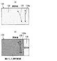
表示部110は、表示画面111(図3(a))上に、車載機器の作動状態、および入力操作用の操作項目を表示する表示装置である。表示部110は、例えば、コンビネーションメータ内に設けられた液晶ディスプレイ部、ヘッドアップディスプレイ装置の表示部(虚像が映し出されるフロントウインドウ部)、あるいはインストルメントパネルに装着されたセンタディスプレイ部等として形成されている。 The
表示画面111上の入力操作用の操作項目としては、例えば、図3(a)に示すように、車載機器の各種機能A〜Dをオンオフするための各種スイッチアイコン112a、112b、112c、112d、および現在の画面表示を上位の画面表示に切替えるためのスイッチアイコン(戻るボタン)112e等となっている。各種スイッチアイコン112a、112b、112c、112d、112eは、例えば、表示画面111の右側領域において、縦方向に並ぶように配置されている。 As an operation item for input operation on the
操作部120は、表示画面111に表示される各種スイッチアイコン112a、112b、112c、112d、112eに対する入力操作を可能とするものである。操作部120は、表示部110とは離れた位置、ここでは、図2に示すように、車両のステアリング50のリングとボスとを繋ぐスポーク51(左側のスポーク51)に設けられて、ステアリング50を握るユーザの親指(左手の親指)によって入力操作ができるようになっている。操作部120は、操作ノブ121、反力発生部122、位置検出センサ123、押操作検出センサ124、および制御部125等を有している。 The
操作ノブ121は、ユーザの指操作によって、操作部120における仮想平面上をスライド移動する部位となっている。操作部120がステアリング50のスポーク51に設けられていることから、ここでは、仮想平面は、ステアリング50のリングの周囲を含む平面となっている。操作部120は、操作ノブ121が仮想平面上をスライドすることから、2軸(x、y軸)スライド式遠隔操作デバイスとなっている。本実施形態では、例えば、x軸を左右方向の軸、y軸を上下方向の軸としている。 The
操作ノブ121を2軸方向にスライド移動させることで、表示画面111には、操作ノブ121のスライド位置に対応するように、例えば、カーソル等のポインタが表示されるようになっている。 By sliding the
反力発生部122は、操作ノブ121のスライド移動に伴って、例えば、表示画面111におけるカーソルが所定のスイッチアイコンに近づいたときに、逆にスイッチアイコンから離れようとすると、そのスイッチアイコンに引き込むような力(操作反力)を操作ノブ121に発生させる部位となっている。 When the
位置検出センサ123は、操作ノブ121が操作される操作範囲126(図3(b))において、現在、操作ノブ121がどの位置にあるのかという位置信号を生成して、制御部125に出力する部位となっている。操作範囲126は、表示画面111の表示領域と対応するように設定されている。そして、操作範囲126には、図3(b)に示すように、予めx、y座標(0、0)ポイント〜(例えば、255、255)ポイントが定義されており、位置検出センサ123は、x、y座標に基づく位置信号を制御部125に出力するようになっている。よって、本実施形態の位置検出は、x、y座標を用いた絶対座標検出となっている。 The
また、操作範囲126には、表示画面111の各種スイッチアイコン112a、112b、112c、112d、112eに対する入力操作を受付け可能とする操作受付け範囲127(図3(d))が、予め設定されている。操作受付け範囲127は、各種スイッチアイコン112a、112b、112c、112d、112eの主に中心領域を上下方向に繋ぐ帯状の領域、および各種スイッチアイコン112a、112b、112c、112d、112dのそれぞれにおいて、オン領域とオフ領域とを合わせた左右方向の帯状の領域として設定されている。 Further, in the
また、操作範囲126には、図3(b)に示すように、各種スイッチアイコン112a、112b、112c、112d、112eに対して、本来あるべき理想的な操作位置をたどる際の軌跡として理想の操作軌跡128a、128bが、予め定義されている。理想の操作軌跡128a、128bは、例えば、各種スイッチアイコン112a、112b、112c、112dを繋ぐ上下方向の理想の操作軌跡128a、および各種スイッチアイコン112a、112b、112c、112dに対して、オン領域とオフ領域とを繋ぐ左右方向の理想の操作軌跡128bがある。 Further, as shown in FIG. 3B, the
更に、操作範囲126には、図3(c)に示すように、ユーザの操作ノブ121の操作に伴って、実際に操作された軌跡として、ユーザの入力操作軌跡129が形成されるようになっている。入力操作軌跡129は、ユーザの操作に応じて、上記の位置検出センサ123によって検出される軌跡である。 Further, as shown in FIG. 3C, a user
押操作検出センサ124は、ユーザが操作ノブ121を押込んだときに押込み信号を生成して、制御部125に出力する部位となっている。尚、操作部120において、押操作検出センサ124は、省略されたものとしてもよい。 The push
制御部125は、位置検出センサ123からの位置信号に基づいて反力発生部122における反力の発生状態を制御する部位となっている。また、制御部125は、位置検出センサ123から得られた位置信号、および押操作検出センサ124から得られた押込み信号を入力操作支援モジュール130に出力するようになっている。 The
入力操作支援モジュール130は、操作部120における入力操作による入力データ(位置信号、押込み信号)に基づいて、車載機器に対する入力操作支援を行うと共に、操作部120におけるユーザの操作感にかかる操作感パラメータを更新する部位となっている。入力操作支援モジュール130は、入力操作受信部131、制御部132、操作感パラメータ更新部133、操作対象GUI(Graphical User Interface)134、および操作感パラメータ送信部135等を有している。入力操作支援モジュール130は、本発明の入力操作支援部に対応する。 The input
入力操作受信部131は、操作部120における入力操作に伴う入力データ(位置信号および押込み信号)を受信する部位となっている。入力操作受信部131は、受信した入力データを制御部132に出力するようになっている。 The input
制御部132は、入力操作受信部131から出力された操作部120の入力データを、操作感パラメータ更新部133、および操作対象GUI134に出力する部位となっている。 The
操作感パラメータ更新部133は、制御部132から出力された入力データを基に、ユーザの入力操作軌跡129を抽出し、理想の操作軌跡128aとの差から入力操作軌跡129の特徴を判定して、操作部120におけるユーザの操作感覚にかかる設定条件としての操作感パラメータを好適なパラメータに更新する部位となっている。操作感パラメータ更新部133は、操作軌跡抽出部133a、操作軌跡記憶部133b、操作軌跡特徴判定部133c、操作感パラメータ算出部133d等を有している。 The operation feeling
操作軌跡抽出部133aは、位置検出センサ123によって得られた位置信号から、操作範囲126における入力操作軌跡129を抽出する部位となっている。操作軌跡抽出部133aは、本発明の抽出部に対応し、以下、操作軌跡抽出部133aを抽出部133aと呼ぶことにする。 The operation
操作軌跡記憶部133bは、抽出部133aで抽出された入力操作軌跡129を記憶する部位となっている。操作軌跡記憶部133bは、本発明の記憶部に対応し、以下、操作軌跡記憶部133bを記憶部133bと呼ぶことにする。 The operation
操作軌跡特徴判定部133cは、操作範囲126における理想の操作軌跡128aと、記憶部133bに記憶された入力操作軌跡129とを比較して、入力操作軌跡129の特徴を判定する部位となっている。操作軌跡特徴判定部133cは、本発明の判定部に対応し、以下、操作軌跡特徴判定部133cを判定部133cと呼ぶことにする。 The operation trajectory
操作感パラメータ算出部133dは、操作部120におけるユーザの操作感にかかる操作感パラメータに対して、判定部133cで判定された入力操作軌跡129の特徴に基づいて、ユーザに合った好適なパラメータを算出する部位となっている。操作感パラメータ算出部133dは、本発明の算出部に対応し、以下、操作感パラメータ算出部133dを算出部133dと呼ぶことにする。算出部133dは、算出した好適なパラメータ値を操作対象GUI134、および操作感パラメータ送信部135に出力するようになっている。 The operation feeling
上記操作感パラメータ更新部133における各部位133a、133b、133c、133dは、それぞれ独立した回路部(ハードウエア)として形成されるものとしてもよいし、あるいはマイクロコンピュータ上でソフトウエアによって仮想的に形成されるものとしてもよい。 The
操作対象GUI134は、車載機器に対するインターフェイス部を形成する部位であり、制御部132から出力された入力データ、および算出部133dから出力された好適なパラメータ値をもとに、車載機器に対する作動指示を行うと共に、この作動指示に基づく表示内容となるように表示部110に表示指示(映像出力)を行うようになっている。また、操作対象GUI134は、表示部110に対して指示をした表示画面情報を判定部133cに出力するようになっている。 The
操作感パラメータ送信部135は、算出部133dから出力された好適なパレメータ値を操作部120の制御部125に送信する部位となっている。 The operation feeling
本入力装置100の構成は、以上のようになっている。 The configuration of the input device 100 is as described above.
ここで、上記のように、本入力装置100においては、操作部120がステアリング50のスポーク51に設けられていることから、ユーザの手の大きさ(親指の長さ)によっては、図3に示すような不具合が起こる場合がある。 Here, as described above, in the input device 100, since the
例えば、図3(b)に示すように、上下方向および左右方向の理想の操作軌跡128a、128bのうち、上下方向の理想の操作軌跡128aを例にした場合、ユーザはステアリング50を握ったまま、スイッチアイコン112dからスイッチアイコン112eを狙って、下から上に向けて親指(左手の親指)で操作ノブ121を操作したとする。しかしながら、ユーザは、親指で操作ノブ121を下から上に向けて操作したつもりであっても、親指は第2関節を中心として弧を描くような動きとなるので、図3(c)に示すように、ユーザの入力操作軌跡129は、理想の操作軌跡128aからずれてしまう場合がある。 For example, as shown in FIG. 3B, when the
そして、操作範囲126には、上記のように、図3(d)に示すような操作受付け範囲127が予め設定されていることから、ユーザは、例えば、操作ノブ121をスイッチアイコン112dの位置からスイッチアイコン112eの位置に移動させたつもりで、操作ノブ121を押操作すると、実際には、スイッチアイコン112aにおけるオフ機能に切り替わってしまう場合がある。 As described above, since the
そこで、本実施形態では、理想の操作軌跡128a、128bに対するユーザの入力操作軌跡129の特徴(ユーザ一人ひとり特徴)を判定して、操作感パラメータを自動的に更新するようになっている。以下、図4〜図14を用いてその詳細について説明する。 Therefore, in the present embodiment, the characteristics of the user's
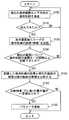
図4は、入力操作支援モジュール130の操作感パラメータ更新部133が行う操作感パラメータ更新制御の全体を示すフローチャートとなっている。ここでは、理想の操作軌跡128a、128bのうち、1つの例として、図3で説明した上下方向の理想の操作軌跡128aの場合について説明する。 FIG. 4 is a flowchart showing the entire operation feeling parameter update control performed by the operation feeling
まず、図4のステップS100で、操作感パラメータ更新部133(抽出部133a)は、現在の操作範囲126における上下方向の入力操作軌跡129を抽出する。ステップS100の詳細は、図5に示すフローチャートのステップS101〜S108となっている。 First, in step S100 of FIG. 4, the operation feeling parameter update unit 133 (
即ち、図5に示すように、ステップS101で、抽出部133aは、入力操作軌跡129の一時記録を開始し、このときの座標(座標1)を取得すると共に、ステップS102で、次の座標(座標2)を取得する。 That is, as shown in FIG. 5, in step S101, the
続いて、ステップS103で、抽出部133aは、座標1と座標2の差分から入力操作軌跡129の方向(上方向か下方向か)を決定する。 Subsequently, in step S103, the
そして、ステップS104で、抽出部133aは、現在のy座標(上下方向の位置座標)は、理想の操作軌跡128aの範囲外(上端より上、あるいは下端より下)か、否かを判定する。 In step S104, the
ステップS104で、否(範囲内にある)と判定すると、抽出部133aは、ステップS105で、更に次の座標(座標n)を取得し(nは3以上)、ステップS106で、座標(n−1)と座標nとの差分から入力操作軌跡129の伸びている方向を決定する。 If it is determined that the result is NO (within the range) in step S104, the
そして、ステップS107で、抽出部133aは、入力操作軌跡129の方向が上下方向に対して変化したかを判定する。ステップS107で否と判定すると、ステップS104に戻り、ステップS104〜S107を繰り返す。また、ステップS107で肯定判定すると、ステップS108に進む。そして、ステップS108で、操作感パラメータ更新部133の記憶部133bは、入力操作軌跡129を一時記録(記憶)して、このフローを終了する。 In step S107, the
尚、ステップS104で肯定判定した場合(範囲外にある場合)は、上記と同様にステップS108に進み、ステップS108で、記憶部133bは、入力操作軌跡129を一時記録(記憶)して、このフローを終了する。 If an affirmative determination is made in step S104 (if out of range), the process proceeds to step S108 as described above, and in step S108, the
図4に戻って、ステップS110では、操作感パラメータ更新部133は、上記ステップS100(S101〜S108)で、入力操作軌跡129が抽出できたか否かを判定して、肯定判定した場合はステップS120に進み、否定判定した場合はステップS100に戻る。 Returning to FIG. 4, in step S <b> 110, the operation feeling
ステップS120では、操作感パラメータ更新部133(抽出部133a、記憶部133b)は、表示画面111ごと(図3(a)とは異なる画面ごと)にユーザの入力操作軌跡129の座標(特徴)を記録(記憶)する。ステップS120の詳細は、図6に示すフローチャートのステップS121〜S124となっている。 In step S120, the operation feeling parameter update unit 133 (
即ち、図6に示すように、まず、ステップS121で、抽出部133aは、上記のステップS100において抽出(記憶)した入力操作軌跡129は、予め定めた閾値以上の長さか否かを判定する。閾値は、例えば、理想の操作軌跡128aの全長に対する所定割合の長さと定義することができる。更に具体的には、図7に示すように、理想の操作軌跡128aに対して、各スイッチアイコン112a、112b、112c、112d、112eに対応する位置を、仮にポイント1〜5と定義して、入力操作軌跡129が、3ポイント(全長の50%)以上、跨ぐ場合を閾値以上の長さと判定する。 That is, as shown in FIG. 6, first, in step S121, the
図7の(a)および(b)の場合では、入力操作軌跡129は、閾値以上の長さ(5、3ポイントに跨る)と判定され、また、図7の(c)の場合では、入力操作軌跡129は、閾値よりも短い(2ポイント)と判定される。 In the case of (a) and (b) in FIG. 7, the
ステップS121で肯定判定すると、ステップS122で、抽出部133aは、閾値以上と判定した入力操作軌跡129における座標(特徴)を抽出する。具体的には、例えば、図8(b)、(c)、(d)のような1回目〜3回目の入力操作軌跡129を抽出したとする。そして、各ポイント1〜5における理想の操作軌跡128b(x軸方向の)と、入力操作軌跡129とが交差する点のx、y座標を、図9に示すように、座標データとして抽出する。 If an affirmative determination is made in step S121, in step S122, the
そして、ステップS123で、記憶部133bは、上記ステップS122の座標データを記録(記憶)する。 In step S123, the
尚、ステップS121で、抽出部133aが抽出した入力操作軌跡129の長さが閾値以上でないと判定すると、記憶部133bは、ステップS124で、その入力操作軌跡129の座標(特徴)は、記録(記憶)しないようになっている。 If it is determined in step S121 that the length of the
つまり、抽出部133aは、理想の操作軌跡128aの長さに対して閾値(所定割合)以上となる入力操作軌跡129を採用して、記録するようになっている。 In other words, the
再び、図4に戻って、ステップS130では、操作感パラメータ更新部133は、現在の画面について、入力操作軌跡129の座標データが、一定回数以上記録できたか否かを判定し、肯定判定した場合は、ステップS140に進む。尚、ステップS130で、否定判定すれば、ステップS100に戻る。 Returning to FIG. 4 again, in step S130, the operation feeling
ステップS140で、操作感パラメータ更新部133(判定部133c)は、記録した入力操作軌跡129の座標データと、現在の画面の理想の操作軌跡128aの座標データとを、図10に示すように比較する。 In step S140, the operation feeling parameter update unit 133 (
図10(a)は、理想の操作軌跡128aの各ポイント1〜5における座標を示し、図10(b)は、ステップS120で抽出、記録されたユーザの入力操作軌跡129の各ポイント1〜5における座標の平均値(図9における平均値)を示している。 10A shows the coordinates of the
判定部133cは、各ポイント1〜5における理想の操作軌跡128aの座標と、ユーザの入力操作軌跡129の座標の平均値との差分(ずれ)を、図10(c)に示すように、算出する。 The
続いて、ステップS150で、判定部133cは、上記ステップS140での比較結果(差分)の最大値が、予め定めた一定値以上か否かを判定し、肯定判定すると、ステップS160に進む。 Subsequently, in step S150, the
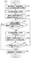
そして、ステップS160では、操作感パラメータ更新部133(算出部133d)は、操作部120における操作感にかかるパラメータに対して、上記比較結果(差分)に基づいて好適なパラメータを算出して、操作感パラメータを更新する。ステップS160の詳細は、図11に示すフローチャートのステップS161〜S165となっている。 In step S160, the operation feeling parameter update unit 133 (
即ち、図11に示すように、まず、ステップS161で、算出部133dは、ユーザの入力操作軌跡129は、理想の操作軌跡128aに対して一部のみがずれているか否かを判定する。ステップS161で肯定判定をすると、ステップS162で、算出部133dは、入力操作軌跡129のずれている部分を操作支援する力(操作反力)を強くする余地が残っているか否かを判定する。そして、ステップS162で肯定判定すると、ステップS163に進む。 That is, as shown in FIG. 11, first, in step S161, the
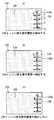
ステップS163では、算出部133dは、図12に示すように、理想の操作軌跡128a(図12(a))に対して、一定値以上ずれている点(図12(b))に対して、実際の入力操作軌跡129が、理想の操作軌跡128aに近づくように、操作反力にかかる操作感パラメータ値を算出する。そして、操作感パラメータ更新部133は、操作感パラメータ値を更新して、操作反力を大きくする(図12(c))。 In step S163, as illustrated in FIG. 12, the
操作感パラメータ更新部133における操作感パラメータ値(反力値の大きさ)の更新は、算出部133dが算出した新しい操作感パラメータ値が、操作感パラメータ送信部135、および操作対象GUI134に出力されることで実行される。 In the update of the operation feeling parameter value (reaction force value) in the operation feeling
また、ステップS162で、算出部133dは、入力操作軌跡129のずれている部分を操作支援する力(操作反力)を強くする余地が残っていないと判定すると、ステップS164に進む。 In step S162, if the
ステップS164では、算出部133dは、図13に示すように、理想の操作軌跡128a、128bおよび操作受付け範囲127(図13(a))において、入力操作軌跡129が一定値以上ずれている点(図13(b))に対して、操作受付け範囲127が実際の入力操作軌跡129に近づくように、操作受付け範囲127をずらすための位置座標を算出する。そして、操作感パラメータ更新部133は、操作受付け範囲127の座標位置を移動させる(図13(c))。ここでは、理想の操作軌跡128aに対する操作受付け範囲127が左側に傾くように、また、スイッチアイコン112aに対応する操作受付け範囲127を左側にずらすように、移動させている。 In step S164, the
操作感パラメータ更新部133における操作感パラメータ値(受付け範囲の位置)の更新は、算出部133dが算出した新しい操作感パラメータ値が、操作感パラメータ送信部135、および操作対象GUI134に出力されることで実行される。 The operation feeling
一方、ステップS161で、算出部133dは、ユーザの入力操作軌跡129は、理想の操作軌跡128aに対して一部のみではなく、全部がずれていると判定すると(図14(a))、操作範囲126に対して、実際の入力操作軌跡129に見合った操作範囲を算出する。そして、ステップS165で、操作感パラメータ更新部133は、操作部120における操作範囲126を縮小する(図14(b))。 On the other hand, when the
即ち、理想の操作軌跡128aの位置が、実際の入力操作軌跡129に重なるように、操作範囲126を、ずれている入力操作軌跡129側(図14中の左側)に縮小する。 That is, the
操作感パラメータ更新部133における操作感パラメータ値(受付け範囲の大きさ)の更新は、算出部133dが算出した新しい操作感パラメータ値が、操作感パラメータ送信部135、および操作対象GUI134に出力されることで実行される。 In the update of the operation feeling parameter value (the size of the acceptance range) in the operation feeling
以上のように本実施形態によれば、ユーザによる操作ノブ121への入力操作軌跡129が抽出部(133a)によって抽出され、抽出された入力操作軌跡は、記憶部133bによって記憶される。また、判定部133cによって、理想の操作軌跡128aと記憶された入力操作軌跡129とが比較されて、ユーザ特有の入力操作軌跡129の特徴(座標)が判定(把握)される。 As described above, according to the present embodiment, the
更に、算出部133dは、入力操作軌跡129の特徴に基づいて、操作部120における操作感にかかるパラメータとして好適なパラメータを算出し、操作感パラメータ更新部133(ステップS160)は、操作部120におけるパラメータを、好適なパラメータに更新していく。 Further, the
よって、従来技術のように、ユーザが操作感にかかるパラメータを更新するために予め複数のパラメータを準備して記憶させておくことや、パラメータを更新するための操作を行う必要がなく、ユーザに手間をかけずに操作感のチューニングをすることが可能となる。 Therefore, unlike the prior art, it is not necessary to prepare and store a plurality of parameters in advance in order to update the parameters related to the user's operational feeling, or to perform an operation for updating the parameters. It is possible to tune the feeling of operation without taking time and effort.
また、本実施形態では、入力操作軌跡129を抽出する際に、抽出部133aは、入力操作軌跡129のうち、理想の操作軌跡128aの長さに対して閾値(所定割合)以上となる入力操作軌跡129を採用するようにしている。よって、不用意に入力された入力データを不採用として、ユーザが意図的に入力操作したと思われる入力データを用いることで、信頼性の高いパラメータの更新が可能となる。 Further, in the present embodiment, when extracting the
また、パラメータ更新の内容の1つとして、操作反力の値を大きくするものを採用している(ステップS163)。これは、操作部120に設けられた反力発生部122を活用したものとして対応が可能であり、有効なパラメータ更新とすることができる。 Further, as one of the contents of the parameter update, one that increases the value of the operation reaction force is adopted (step S163). This can be handled by utilizing the
この操作反力の値を大きくする変更にあたっては、入力操作軌跡129が理想の操作軌跡128aに対して、一部がずれている場合で、且つ、操作反力による補正の余地が残っている場合に行われるようにしているので、効果的なパラメータ更新とすることができる。 When changing the value of the operation reaction force to be large, when the
また、パラメータ更新の他の内容として、操作部120における操作受付け範囲127を、理想の操作軌跡128aに対して入力操作軌跡129がずれる分だけ移動させることも採用しており(ステップS164)、上記の操作反力を変更するものとは別の内容の対応を提供可能としている。 As another content of the parameter update, it is also adopted that the
この場合は、入力操作軌跡129が理想の操作軌跡128aに対して、一部がずれている場合で、且つ、操作反力による補正の余地が残っていない場合に行われるようにしているので、操作反力のみに頼らないパラメータ更新とすることができる。 In this case, since the
また、パラメータ更新の更に他の内容として、入力操作軌跡129を受付ける操作受付け範囲127を、理想の操作軌跡128aに対して入力操作軌跡129がずれる分を補正するように縮小させることも採用しており(ステップS165)、そもそも、ユーザ一人ひとりの手の大きさの違いにかかるずれの補正を可能としている。 Further, as another content of the parameter update, it is also adopted that the
この場合は、入力操作軌跡129が理想の操作軌跡128aに対して、すべてがずれている場合に採用して効果的となる。 In this case, it is effective to adopt when the
(第2実施形態)
第2実施形態を図15〜図18に示す。第2実施形態は、上記第1実施形態に対して、操作部120を絶対座標検出タイプのものから、相対座標検出タイプのものに変更したものとしている。尚、操作部120は、ステアリング50の右側のスポーク51に設けられており、ユーザの右手の親指によって入力操作が実施されるものとなっている。操作部120は、上下方向、および左右方向の十字操作入力が可能となっている。(Second Embodiment)
A second embodiment is shown in FIGS. In the second embodiment, the
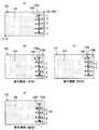
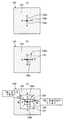
図15(a)に示すように、操作部120の操作範囲126においては、中央位置に対応するようにスライド操作のゼロ点128cが形成されている。また、ユーザがゼロ点128cを中心にして、十字操作をする際に、ゼロ点128cを中心として上下方向となる理想の操作軌跡128aと、ゼロ点128cを中心として左右方向となる理想の操作軌跡128bとが形成されている。 As shown in FIG. 15A, a slide operation zero
また、図15(b)に示すように、ユーザの入力操作軌跡129は、例えば、破線矢印のようになって、理想の操作軌跡128aとずれる場合がある。 Further, as shown in FIG. 15B, the user's
更に、図15(c)に示すように、操作受付け範囲127は、図中の白抜きで表示した領域となっており、中心領域、上側領域、下側領域、右側領域、および左側領域となっている。各領域は、車載機器のそれぞれ異なる機能を作動させるための受付範囲となっている。 Further, as shown in FIG. 15C, the
ここで、上記図15(b)で説明したような入力操作軌跡129のずれが発生する場合であると、上下方向の入力操作軌跡129によって、操作受付け範囲127のうち、上側領域を狙ったにもかかわらず、右側領域への入力がされてしまう場合がある。同様に、左右方向の入力操作軌跡129によって、操作受付け範囲127のうち、左側領域を狙ったにもかかわらず、入力操作軌跡129が到達しておらず、入力できない場合がある。 Here, when the deviation of the
このような不具合の可能性に対して、本実施形態では、上記第1実施形態と同様に、操作感パラメータ更新制御を行うようになっている。操作感パラメータ更新制御の要領は、上記第1実施形態と同様である。図16〜図18には、操作感パラメータ更新の具体的な事例を示している(3種)。 In the present embodiment, for the possibility of such a problem, the operational feeling parameter update control is performed in the same manner as in the first embodiment. The point of operation feeling parameter update control is the same as that of the first embodiment. 16 to 18 show specific examples of operation feeling parameter update (three types).
図16は、第1実施形態のステップS163と同様に、ユーザの入力操作軌跡129が理想の操作軌跡128aに近づくように、操作反力(左向きの力)を大きくした例である。 FIG. 16 is an example in which the operation reaction force (leftward force) is increased so that the user's
図17は、第1実施形態のステップS164と同様に、理想の操作軌跡128aがユーザの入力操作軌跡129に近づくように、理想の操作軌跡128a、128b、および操作受付け範囲127を、平行移動した例である。 In FIG. 17, as in step S <b> 164 of the first embodiment, the
図18は、第1実施形態のステップS165と同様に、ユーザの入力操作軌跡129の長さに合せて、操作受付け範囲127を縮小した例である。 FIG. 18 is an example in which the
これにより、操作部120において、相対座標検出タイプのものを用いるものであっても、上記第1実施形態と同様の効果を奏することができる。 Thereby, even if the
(その他の実施形態)
上記各実施形態では、ステップS160(操作感パラメータの更新ステップ)において、操作反力を大きくする、操作受付け範囲127を移動する、および操作範囲126を縮小するといった3つの内容を実行するものとして説明した。しかしながら、これに限らず、ステップS161、およびステップS162の条件を廃止して、いずれか1つを実行するものとしてもよい。あるいは3つのうちの、少なくとも1を実行するものとしてもよい。(Other embodiments)
In each of the above-described embodiments, in step S160 (operation feeling parameter update step), the description will be made on the assumption that three contents of increasing the operation reaction force, moving the
また、上記各実施形態では、入力操作軌跡129、および理想の操作軌跡128aの方向を主に、上下方向の操作軌跡として説明したが、これに限定されるものではなく、他の方向における操作軌跡に対して、操作パラメータを更新するものとして活用できる。 In each of the above embodiments, the directions of the
50 ステアリング
100 入力装置
112a、112b、112c、112d、112e スイッチアイコン(操作項目)
120 操作部
121 操作ノブ
122 反力発生部
130 入力操作モジュール
133 操作感パラメータ更新部
133a 操作軌跡抽出部(抽出部)
133b 操作軌跡記憶部(記憶部)
133c 操作軌跡特徴判定部(判定部)
133d 操作感パラメータ算出部(算出部)
S160 操作感パラメータ更新ステップ(更新部)50 Steering 100
DESCRIPTION OF
133b Operation locus storage unit (storage unit)
133c Operation locus feature determination unit (determination unit)
133d Operation feeling parameter calculation unit (calculation unit)
S160 Operation feeling parameter update step (update unit)
Claims (8)
Translated fromJapanese前記表示部とは離れた位置に設けられて、前記操作項目に対する入力操作を可能とする操作部(120)と、
前記入力操作による入力データに基づいて、前記車載機器に対する入力操作支援を行う入力操作支援部(130)と、を備える入力装置において、
前記操作部は、平面上を移動する操作ノブ(121)を有し、車両のステアリング(50)に設けられて、前記ステアリングを握るユーザの親指によって前記操作ノブが操作されるようになっており、
前記入力操作支援部は、
前記親指による前記操作ノブへの入力操作軌跡を抽出する抽出部(133a)と、
抽出された前記入力操作軌跡を記憶する記憶部(133b)と、
前記操作項目の配置に対して本来あるべき理想の操作軌跡と、記憶された前記入力操作軌跡とを比較して、記憶された前記入力操作軌跡の特徴を判定する判定部(133c)と、
前記操作部における操作感にかかるパラメータに対して、前記入力操作軌跡の前記特徴に基づいて、好適なパラメータとして算出する算出部(133d)と、
前記操作部における前記パラメータを、前記好適なパラメータに更新する更新部(S160)と、を有する入力装置。A display unit (110) on which an operation state of the in-vehicle device and operation items for operation (112a, 112b, 112c, 112d, 112e) are displayed;
An operation unit (120) provided at a position apart from the display unit and enabling an input operation to the operation item;
In an input device comprising: an input operation support unit (130) that performs input operation support for the in-vehicle device based on input data by the input operation;
The operation unit has an operation knob (121) that moves on a plane, is provided on a steering (50) of a vehicle, and the operation knob is operated by a user's thumb that holds the steering. ,
The input operation support unit
An extraction unit (133a) for extracting an input operation locus to the operation knob by the thumb;
A storage unit (133b) for storing the extracted input operation trajectory;
A determination unit (133c) that compares the ideal operation trajectory that should originally be with respect to the arrangement of the operation items and the stored input operation trajectory to determine characteristics of the stored input operation trajectory;
A calculation unit (133d) that calculates a suitable parameter based on the characteristics of the input operation trajectory with respect to the parameter related to the operational feeling in the operation unit;
An input device comprising: an update unit (S160) that updates the parameter in the operation unit to the suitable parameter.
前記好適なパラメータへの変更は、前記理想の操作軌跡に対する前記入力操作軌跡のずれ分を補正するように前記操作反力の値を大きくする変更である請求項1または請求項2に記載の入力装置。The operation unit includes a reaction force generation unit (122) that generates an operation reaction force on the thumb of the user.
The input according to claim 1, wherein the change to the suitable parameter is a change to increase the value of the operation reaction force so as to correct a deviation of the input operation track with respect to the ideal operation track. apparatus.
前記入力操作軌跡を受付ける範囲を移動させる変更は、前記入力操作軌跡が前記理想の操作軌跡に対して、一部がずれている場合で、且つ、前記操作反力による補正の余地が残っていない場合に行われる請求項5に記載の入力装置。The operation unit includes a reaction force generation unit (122) that generates an operation reaction force on the thumb of the user.
The change to move the range for receiving the input operation locus is when the input operation locus is partially deviated from the ideal operation locus and there is no room for correction by the operation reaction force. 6. The input device according to claim 5, which is performed in a case.
Priority Applications (1)
| Application Number | Priority Date | Filing Date | Title |
|---|---|---|---|
| JP2016224253AJP6610512B2 (en) | 2016-11-17 | 2016-11-17 | Input device |
Applications Claiming Priority (1)
| Application Number | Priority Date | Filing Date | Title |
|---|---|---|---|
| JP2016224253AJP6610512B2 (en) | 2016-11-17 | 2016-11-17 | Input device |
Publications (2)
| Publication Number | Publication Date |
|---|---|
| JP2018081564Atrue JP2018081564A (en) | 2018-05-24 |
| JP6610512B2 JP6610512B2 (en) | 2019-11-27 |
Family
ID=62198955
Family Applications (1)
| Application Number | Title | Priority Date | Filing Date |
|---|---|---|---|
| JP2016224253AExpired - Fee RelatedJP6610512B2 (en) | 2016-11-17 | 2016-11-17 | Input device |
Country Status (1)
| Country | Link |
|---|---|
| JP (1) | JP6610512B2 (en) |
Cited By (1)
| Publication number | Priority date | Publication date | Assignee | Title |
|---|---|---|---|---|
| JP2020024575A (en)* | 2018-08-07 | 2020-02-13 | 株式会社デンソー | Input device |
- 2016
- 2016-11-17JPJP2016224253Apatent/JP6610512B2/ennot_activeExpired - Fee Related
Cited By (2)
| Publication number | Priority date | Publication date | Assignee | Title |
|---|---|---|---|---|
| JP2020024575A (en)* | 2018-08-07 | 2020-02-13 | 株式会社デンソー | Input device |
| WO2020031548A1 (en)* | 2018-08-07 | 2020-02-13 | 株式会社デンソー | Input device |
Also Published As
| Publication number | Publication date |
|---|---|
| JP6610512B2 (en) | 2019-11-27 |
Similar Documents
| Publication | Publication Date | Title |
|---|---|---|
| US7116317B2 (en) | Systems and methods for user interfaces designed for rotary input devices | |
| JP5413448B2 (en) | Display system, display device, and operation device | |
| JP5641001B2 (en) | Display control apparatus and display system | |
| US10967737B2 (en) | Input device for vehicle and input method | |
| US20170329489A1 (en) | Operation input apparatus, mobile terminal, and operation input method | |
| JP2012190215A (en) | Input processor, input processing method, and program | |
| US9063569B2 (en) | Vehicular device | |
| JP2009276993A (en) | Input device | |
| JP2009009261A (en) | Touch panel display device and control method | |
| JP2014238621A (en) | Input receiving device | |
| US10180756B2 (en) | Input apparatus | |
| US20190391736A1 (en) | Input device and input method | |
| US20130201126A1 (en) | Input device | |
| JP6610512B2 (en) | Input device | |
| US11630564B2 (en) | Information processing device and program | |
| JPWO2019073537A1 (en) | Display control device, display control method, display control program, and electronic device | |
| CN109656434B (en) | Display control device | |
| JP2012027538A (en) | Electronic apparatus | |
| JP2010122795A (en) | Electronic apparatus and method of controlling the same | |
| JP2016103047A (en) | Electronic device, in-vehicle device including the electronic device, and instruction method of processing to be executed by means of the electronic device | |
| US20240249898A1 (en) | Operation receiving device | |
| JP6888590B2 (en) | Input device | |
| JP7628375B2 (en) | Navigation Device | |
| JP7118271B2 (en) | Input control device, input device, and input control method | |
| JP6489253B2 (en) | Display device and in-vehicle device operation system |
Legal Events
| Date | Code | Title | Description |
|---|---|---|---|
| A621 | Written request for application examination | Free format text:JAPANESE INTERMEDIATE CODE: A621 Effective date:20190122 | |
| A131 | Notification of reasons for refusal | Free format text:JAPANESE INTERMEDIATE CODE: A131 Effective date:20190827 | |
| A977 | Report on retrieval | Free format text:JAPANESE INTERMEDIATE CODE: A971007 Effective date:20190830 | |
| A521 | Request for written amendment filed | Free format text:JAPANESE INTERMEDIATE CODE: A523 Effective date:20190913 | |
| TRDD | Decision of grant or rejection written | ||
| A01 | Written decision to grant a patent or to grant a registration (utility model) | Free format text:JAPANESE INTERMEDIATE CODE: A01 Effective date:20191001 | |
| A61 | First payment of annual fees (during grant procedure) | Free format text:JAPANESE INTERMEDIATE CODE: A61 Effective date:20191014 | |
| R151 | Written notification of patent or utility model registration | Ref document number:6610512 Country of ref document:JP Free format text:JAPANESE INTERMEDIATE CODE: R151 | |
| LAPS | Cancellation because of no payment of annual fees |