JP2018080991A - Portable atomic watch - Google Patents
Portable atomic watchDownload PDFInfo
- Publication number
- JP2018080991A JP2018080991AJP2016223029AJP2016223029AJP2018080991AJP 2018080991 AJP2018080991 AJP 2018080991AJP 2016223029 AJP2016223029 AJP 2016223029AJP 2016223029 AJP2016223029 AJP 2016223029AJP 2018080991 AJP2018080991 AJP 2018080991A
- Authority
- JP
- Japan
- Prior art keywords
- antenna
- portable radio
- windshield
- arc
- dipole antenna
- Prior art date
- Legal status (The legal status is an assumption and is not a legal conclusion. Google has not performed a legal analysis and makes no representation as to the accuracy of the status listed.)
- Granted
Links
- 239000011521glassSubstances0.000claimsabstractdescription15
- 239000002184metalSubstances0.000claimsdescription20
- 230000002093peripheral effectEffects0.000claimsdescription15
- 238000004804windingMethods0.000claimsdescription15
- 230000035945sensitivityEffects0.000abstractdescription84
- 238000010586diagramMethods0.000description16
- 230000010287polarizationEffects0.000description12
- 239000000463materialSubstances0.000description11
- 239000010408filmSubstances0.000description8
- 230000000052comparative effectEffects0.000description7
- 230000000694effectsEffects0.000description5
- 238000000034methodMethods0.000description4
- 239000003989dielectric materialSubstances0.000description3
- 239000010409thin filmSubstances0.000description3
- MCMNRKCIXSYSNV-UHFFFAOYSA-NZirconium dioxideChemical compoundO=[Zr]=OMCMNRKCIXSYSNV-UHFFFAOYSA-N0.000description2
- 230000005540biological transmissionEffects0.000description2
- 239000000919ceramicSubstances0.000description2
- 230000001788irregularEffects0.000description2
- 230000007246mechanismEffects0.000description2
- 238000012986modificationMethods0.000description2
- 230000004048modificationEffects0.000description2
- 238000007639printingMethods0.000description2
- 238000004904shorteningMethods0.000description2
- 229910001220stainless steelInorganic materials0.000description2
- 239000010935stainless steelSubstances0.000description2
- 229920003002synthetic resinPolymers0.000description2
- 239000000057synthetic resinSubstances0.000description2
- 230000009471actionEffects0.000description1
- 230000002411adverseEffects0.000description1
- 230000008859changeEffects0.000description1
- 239000011248coating agentSubstances0.000description1
- 238000000576coating methodMethods0.000description1
- 239000004020conductorSubstances0.000description1
- 230000008878couplingEffects0.000description1
- 238000010168coupling processMethods0.000description1
- 238000005859coupling reactionMethods0.000description1
- 125000004122cyclic groupChemical group0.000description1
- 238000005034decorationMethods0.000description1
- 230000005684electric fieldEffects0.000description1
- 238000007667floatingMethods0.000description1
- 239000011888foilSubstances0.000description1
- 239000012212insulatorSubstances0.000description1
- 238000007733ion platingMethods0.000description1
- 238000010030laminatingMethods0.000description1
- 239000004973liquid crystal related substanceSubstances0.000description1
- 239000007769metal materialSubstances0.000description1
- 229920003023plasticPolymers0.000description1
- 230000005855radiationEffects0.000description1
- 229910052594sapphireInorganic materials0.000description1
- 239000010980sapphireSubstances0.000description1
- 239000005361soda-lime glassSubstances0.000description1
- 238000004544sputter depositionMethods0.000description1
- 239000000758substrateSubstances0.000description1
- 238000007740vapor depositionMethods0.000description1
Images


Landscapes
- Support Of Aerials (AREA)
- Electric Clocks (AREA)
- Electromechanical Clocks (AREA)
Abstract
Description
Translated fromJapanese本発明は、携帯型電波時計に関する。 The present invention relates to a portable radio timepiece.
腕時計、懐中時計などの携帯型時計に関し、特に、腕時計において、外部電波を受信して時刻修正を行う電波時計が知られている。かかる電波時計は、受信しようとする外部電波の周波数や偏波に応じた形式のアンテナを備える。 Regarding portable watches such as watches and pocket watches, particularly, watches are known which receive external radio waves and correct their time. Such a radio timepiece includes an antenna having a format corresponding to the frequency and polarization of an external radio wave to be received.
特許文献1には、窓材の内面上、外周部に沿って周回する形状に絶縁体を介して薄膜状に形成された胴体層を積層してなるアンテナを備えた時計が記載されている。 Patent Document 1 describes a timepiece including an antenna formed by laminating a body layer formed in a thin film shape via an insulator in a shape that circulates along an outer peripheral portion on the inner surface of a window member.
特許文献2には、環状の誘電体に、環状の一部を切欠いた形状の導電性材料から形成されたアンテナパターンを形成したアンテナ体を備えた電子時計が記載されている。同文献には、かかるアンテナパターンに対し、1カ所の給電部から給電され、又は2カ所の給電部から平衡給電されることが記述されている。
特許文献3には、ダイポールアンテナにおけるダイポール素子長を互いに異なるものとし、短い方のダイポール素子をホイップアンテナとして動作させることによる、2周波共用アンテナ装置が記載されている。 Patent Document 3 describes a dual-frequency antenna apparatus in which dipole element lengths of dipole antennas are different from each other and a shorter dipole element is operated as a whip antenna.
携帯型電波時計のケースや裏蓋を金属材料とする場合があり、そのような場合には、ケースが外部電波を受信する際の妨げとなりうる。特に、外部電波として、時刻情報を含むGPS(Global Positioning System)電波のようにUHF帯等の高周波帯を使用する場合には、電波がケースや裏蓋により遮られるため、外部電波の受信可能な入射方向は、携帯型電波時計の風防ガラス側(すなわち、上側)からのものが主となる。 The case and back cover of the portable radio timepiece may be made of a metal material. In such a case, the case may be a hindrance when receiving external radio waves. In particular, when a high frequency band such as a UHF band is used as an external radio wave such as a GPS (Global Positioning System) radio wave including time information, the external radio wave can be received because the radio wave is blocked by the case or the back cover. The incident direction is mainly from the windshield side (that is, the upper side) of the portable radio timepiece.
しかしながら、これまで携帯型電波時計に対し適用が提案されている環状アンテナは、利得の指向性が対称であるため、風防ガラス側以外に向く利得は受信に寄与しない。 However, since the annular antenna that has been proposed to be applied to portable radio timepieces has a symmetric gain directivity, the gain directed to the side other than the windshield does not contribute to reception.
本発明はかかる観点に立ちなされたものであり、その解決しようとする課題は、風防ガラス側への利得を高め、それにより携帯型電波時計の受信感度を高めることである。 The present invention has been conceived from such a viewpoint, and the problem to be solved is to increase the gain to the windshield, thereby increasing the reception sensitivity of the portable radio timepiece.
上記課題を解決すべく本出願において開示される発明は種々の側面を有しており、それら側面の代表的なものの概要は以下のとおりである。 The invention disclosed in the present application in order to solve the above problems has various aspects, and the outline of typical aspects of the aspects is as follows.
(1)風防ガラスと、前記風防ガラスの下面側であって、前記風防ガラスの外周縁に沿って弧状に設けられたアンテナ線と、前記アンテナ線の弧の中間点からいずれかの端部に偏った位置に設けられた給電点を有するダイポールアンテナと、前記アンテナ線に接する誘電体と、を有する携帯型電波時計。 (1) Windshield glass, an antenna line provided on the lower surface side of the windshield glass along the outer peripheral edge of the windshield glass, and an intermediate point between the arcs of the antenna lines, at any end portion A portable radio-controlled timepiece having a dipole antenna having a feeding point provided at a biased position and a dielectric in contact with the antenna wire.
(2)(1)において、前記誘電体は、前記風防ガラスであり、前記アンテナ線は、前記風防ガラスの下面に配置される携帯型電波時計。 (2) The portable radio timepiece according to (1), wherein the dielectric is the windshield, and the antenna wire is disposed on a lower surface of the windshield.
(3)(1)又は(2)において、前記給電点は、上面から見て、前記アンテナ線の弧の中間点から時計回りの方向に偏った位置に設けられる請求項1に記載の携帯型電波時計。 (3) The portable type according to (1) or (2), wherein the feeding point is provided at a position offset in a clockwise direction from an intermediate point of the arc of the antenna line when viewed from above. Radio clock.
(4)(1)〜(3)のいずれかにおいて、前記アンテナ線の弧の切欠き部に、前記アンテナ線と同心の弧状に形成され、前アンテナ線から浮遊したダミー線を有する携帯型電波時計。 (4) In any one of (1) to (3), a portable radio wave having a dummy line that is formed in an arc shape concentric with the antenna line in a notch portion of the arc of the antenna line and floats from the front antenna line clock.
(5)(1)〜(4)のいずれかにおいて、前記風防ガラスと、前記アンテナ線の間に、環状の誘電体膜を有する携帯型電波時計。 (5) The portable radio timepiece according to any one of (1) to (4), wherein an annular dielectric film is provided between the windshield glass and the antenna wire.
(6)(1)〜(5)のいずれかにおいて、上面から見て、前記アンテナ線の弧の切欠き部に次に掲げる少なくともいずれかが配置される携帯型電波時計。(a)巻真。(b)ソーラーセルとの接続部。(c)受信中を示す指針。(d)巻真に連なる金属製歯車。(e)電池。 (6) The portable radio timepiece according to any one of (1) to (5), wherein at least one of the following is arranged in a notch portion of the arc of the antenna wire as viewed from above. (A) winding true. (B) Connection part with solar cell. (C) A guideline indicating reception. (D) A metal gear connected to the winding stem. (E) Battery.
(7)(1)〜(6)のいずれかにおいて、前記給電点は、次に掲げる少なくともいずれかと上面から見て重ならない位置に設けられる携帯型電波時計。(d)文字板上に設けられた金属製時字及びその径方向外側領域。(e)受信中を示す指針。 (7) The portable radio timepiece according to any one of (1) to (6), wherein the feeding point is provided at a position that does not overlap with at least one of the following when viewed from above. (D) Metal time letters provided on the dial and their radially outer regions. (E) A guideline indicating that data is being received.
(8)(7)において、前記給電点は、次に掲げる少なくともいずれかと上面から見て重なる位置に設けられる携帯型電波時計。(f)文字板上に設けられた特定の2の金属性装飾部材の中間位置。(g)受信結果を示す指針。 (8) The portable radio timepiece according to (7), wherein the feeding point is provided at a position overlapping with at least one of the following when viewed from above. (F) An intermediate position between two specific metallic decorative members provided on the dial. (G) A guideline indicating the reception result.
(9)(1)〜(8)のいずれかにおいて、前記給電点に形成された、下側に凹となる導電性の受け部と、前記受け部に下面側から接触する弾性ピンと、を有する携帯型電波時計。 (9) In any one of (1) to (8), a conductive receiving portion that is formed on the feeding point and is concave on the lower side, and an elastic pin that contacts the receiving portion from the lower surface side. Portable radio clock.
上記(1)又は(2)の側面によれば、携帯型電波時計のアンテナにおいて、風防ガラス側への利得を高めることができる。 According to the above aspect (1) or (2), in the antenna of the portable radio timepiece, the gain to the windshield side can be increased.
上記(3)の側面によれば、携帯型電波時計のアンテナにおいて、右偏波についての風防ガラス側への利得を高めることができる。 According to the side surface of (3) above, in the antenna of the portable radio timepiece, the gain of the right polarized wave toward the windshield can be increased.
上記(4)の側面によれば、外観上のアンテナ形状をほぼ環状とすることができる。 According to the side surface of the above (4), the antenna shape on the appearance can be made substantially annular.
上記(5)の側面によれば、波長短縮効果が得られるとともに、非環状のアンテナを環状の目隠しにて覆うことができる。 According to the side surface of the above (5), the wavelength shortening effect can be obtained and the non-annular antenna can be covered with the annular blindfold.
上記(6)〜(8)の側面によれば、携帯型電波時計が備える各種部材による受信感度への影響を低減できる。 According to the above aspects (6) to (8), it is possible to reduce the influence of various members included in the portable radio timepiece on the reception sensitivity.
上記(9)の側面によれば、携帯型電波時計の組立時や、外部からの衝撃による、アンテナとの接触不良の発生を防止できる。 According to the above aspect (9), it is possible to prevent the occurrence of poor contact with the antenna when the portable radio timepiece is assembled or due to an external impact.
<第1の実施形態>
以下、本発明の第1の実施形態に係る携帯型電波時計100を図1〜図11を参照しつつ説明する。<First Embodiment>
Hereinafter, a
図1は、本発明の第1の実施形態に係る携帯型電波時計100の上面図である。携帯型電波時計100は、ここでは腕時計として示しているが、その他の形式、例えば、懐中時計であってもよい。携帯型電波時計100は、図示の通り、アナログ式の電子時計であるが、一部に液晶表示器などを用いたデジタル表示を備えるものであってもよい。なお、図1では、携帯型電波時計100を腕に装着するためのバンドは図示を省略している。 FIG. 1 is a top view of a
携帯型電波時計100は、外装ケース1の内部に、時計の機構部材であるいわゆるムーブメントを収容したものである。図1で見て、携帯型電波時計100の文字板2のほぼ中央を軸として、時針、分針及び秒針からなる指針である時刻針3が、また、この例では、文字板2の12時側、9時側及び6時側の位置に副針4が設けられている。副針4の周囲には、環状の装飾部材5が文字板上に設けられている。文字板2の外周縁には、時刻を示す目印、しいわゆる時字6が1時間おきに取り付けられている(図中では、煩雑となるため12時位置の時字6にのみ符号を付した)。さらに、文字板2の外周縁の4時と5時の間の位置には日窓7が開口されており、日窓7を通してその下の日板による日付表示が見えている。 The
これら文字板2と各指針(時刻針3及び副針4)は風防ガラス8により保護されている。風防ガラス8は、外装ケース1のベゼル9に嵌めこまれ、取り付けられている。ベゼル9の表面には、電波の受信状況を示すための目印となる表示、図1では「NG」、「OK」及び「RX」が各々図示の位置に刻印されている。また、外装ケース1の3時側側面には竜頭10が、2時及び4時側側面にはそれぞれプッシュボタン11が取り付けられている。さらに、同図には、竜頭10が取り付けられる軸である巻真12の外形が破線で示されている。 The
以上示した携帯型電波時計100のデザインは一例である。個別具体的な時計の板面のデザインは周知の通り様々であり、本実施形態に関しても、他のデザインであってもよい。 The design of the
本明細書では、以降、携帯型電波時計100の中心位置から見て、風防ガラス8に向く方向を上方向と呼び、上方向を向く面や側をそれぞれ上面、上側と呼び、その反対方向を下方向と呼び、下方向を向く面や側をそれぞれ下面、下側と呼ぶ。 In the present specification, the direction facing the
また、携帯型電波時計100の各部材の材質は限定されないが、本実施形態で示した例では、外装ケース1の胴及び裏蓋はステンレスなどの金属、ベゼルはジルコニアセラミックス等の高誘電体またはステンレスなどの金属である。また、装飾部材5、時字6はその質感による装飾性のため、金属製であり、時刻針3及び副針4の一部又は全部も同様の理由により、金属製である。竜頭10、プッシュボタン11及び巻真12も金属製である。風防ガラス8は一般的なソーダ石灰ガラスの他、サファイアガラスなど種々の材質のガラスであってよいし、いわゆる有機ガラス、すなわち、透明プラスチックなどの透明な風防部材も含む。 The material of each member of the portable radio-controlled
携帯型電波時計100では、受信用アンテナとして、ダイポールアンテナ13を用いている。ダイポールアンテナ13は、風防ガラス8の下面の外周縁に、弧状に形成されたアンテナ線14と、アンテナ線14の弧の中間点からいずれかの端部に偏った位置に設けられた給電点15を有しており、このダイポールアンテナ13は、本実施形態に係る携帯型電波時計100では、上側から図1に示したように、視認可能である。 The
アンテナ線14は、この例では、風防ガラス8の外周縁に沿って、4時半の位置から時計回りに1時半の位置までのおよそ270°にわたる弧状に設けられている。アンテナ線14の弧の中心位置(中心点)は、ここでは、時刻針3の軸と一致している。この場合、アンテナ線14の弧の中間点は、その弧上で、1時半の位置と4時半の位置から等距離となる位置、すなわち、9時の位置であるが、給電点15は、かかる中間点から時計回りの方向に偏った位置となる、10時半の位置に設けられている。給電点15には、その位置からアンテナ線14の互いに反対方向の線に給電するため、下側から電極を接触させるために、アンテナ線14の幅が太くなる部分が隣り合うように2カ所設けられている。 In this example, the
一方、風防ガラス8の外周縁に沿って、1時半の位置から時計回りに4時半の位置までのおよそ90°にわたる部分は、アンテナ線14の弧の切欠き部(すなわち、アンテナ線14と同心の円を考えた場合に、アンテナ線14が配置されない領域)となっているが、その部分には、アンテナ線14と同心の弧状に形成されたダミー線16が設けられている。ダミー線16は、アンテナ線14と電気的には接続せず、浮遊している。そのため、図1に示されているように、1時半の位置と、4時半の位置において、アンテナ線14とダミー線16との間には若干の隙間が設けられている。この隙間の幅は、受信しようとする電波の周波数に対して、アンテナ線14とダミー線16とが有意に容量性カップリングを生じない程度であればよく、UHF帯であれば、0.5〜1mm程度あれば十分である。 On the other hand, along the outer peripheral edge of the
アンテナ線14及びダミー線16は、同材質であることが望ましく、いずれも、風防ガラス8の下面に形成された金属薄膜である。アンテナ線14及びダミー線16の作成方法は限定されず、金属箔の貼り付け、蒸着、導電性ペーストを用いた塗布や印刷など、公知のいかなる方法を用いてもよい。 The
なお、ダミー線16は、アンテナ線14が上側から視認可能であるために、その弧の切欠き部が違和感を与えないようにするためのものである。したがって、ダミー線16の材質は、アンテナ線14と視覚的に区別が付きがたいものであればどのようなものであってもよく、必ずしも同材質でなければならないわけではない。 The
また、風防ガラス8のアンテナ線14及びダミー線16が設けられている周縁部の下側には見返しリング17が設けられている。見返しリング17は、文字板2の外縁部に、外装ケース1の内面と自然に連続する斜面を設置する装飾部材である。見返しリング17は、合成樹脂或いはセラミックスなどの誘電体で作成される。 Further, a
なお、本明細書では、高誘電体を、高誘電率を有する材料の意味で用い、その比誘電率がおおむね20以上となる材質を高誘電体と称する。これに対し、誘電体は、その比誘電率がおおむね20未満の材質を指すものとして用いる。 In the present specification, a high dielectric is used to mean a material having a high dielectric constant, and a material having a relative dielectric constant of approximately 20 or more is referred to as a high dielectric. On the other hand, a dielectric is used to indicate a material whose relative dielectric constant is generally less than 20.
以上説明した本実施形態に係る携帯型電波時計100では、電波の受信用のアンテナがダイポールアンテナ13であり、そしてそのアンテナ線14のアンテナ長が、給電点15に対して非対称であること、また、アンテナ線14が風防ガラス8の下面に設けられていることを重要な特徴の一つとしている。この特徴は、ダイポールアンテナ13の指向性をより上側に先鋭化させ、受信感度を向上させるという効果をもたらす。 In the portable radio-controlled
このことについて、図2A〜8Bを参照してより詳しく説明する。 This will be described in more detail with reference to FIGS.
図2Aは、比較例として示す弧状のダイポールアンテナ13aの平面形状を示す図である。ここで示すダイポールアンテナ13aは、アンテナ線14が半円形状であり、両端からの中間位置に給電点15が設けられている。したがって、給電点15からのアンテナ線14のアンテナ長は1/4円周に等しく、対称である。また、同図では、y方向を平面視においてアンテナ線14の対称軸と一致する方向とし、x方向をそれに直交する方向に座標をとっている。z方向は紙面に垂直上向きであり、携帯型電波時計100の上方向と一致するものとする。そして、この例で示すダイポールアンテナ13aは独立した構成を有しており、風防ガラス8の下面に形成されたものではないものとする。 FIG. 2A is a diagram showing a planar shape of an arc-shaped
図2Aに示したダイポールアンテナ13aのx−z平面における感度指向特性(放射指向特性に等しい)を図3Aに示す。同図では、z軸方向を0度として、x軸方向を90度方向にとった場合のゲインを示している。 FIG. 3A shows sensitivity directivity characteristics (equal to radiation directivity characteristics) in the xz plane of the
図3Aに示すように、ダイポールアンテナ13aの感度指向特性は、一般的な直線状の対称アンテナ線を持つダイポールアンテナの感度指向特性とほとんど変わらず、上下対称の8の字形状を示す。また、ここでは図示は省略するが、右旋円偏波と左旋円偏波に対する感度指向特性に差異はなく、同型の8の字形状となる。 As shown in FIG. 3A, the sensitivity directivity characteristic of the
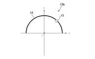
図2Bは、さらなる比較例として示す弧状のダイポールアンテナ13bの平面形状を示す図である。ここで示すダイポールアンテナ13bは、図2Aに示したダイポールアンテナ13aに対し、給電点15の位置がアンテナ線14の中間点からx方向(すなわち、時計回り)に偏った位置に設けられている点が異なっている。そして、給電点15からx方向側の短いアンテナ線14のアンテナ長は1/8円周であり、その逆となる−x方向側の長いアンテナ線14のアンテナ長は3/8円周となっている。その他の点は同一であり、風防ガラス8は設けられていない。 FIG. 2B is a diagram showing a planar shape of an arc-shaped
図3Bは、図2Bに示したダイポールアンテナ13bの感度指向特性を示す図である。本図でも、z軸方向を0度として、x軸方向を90度方向にとった場合のゲインを示しており、この図示は図5A、5B、6A、6B、8A及び8Bでも同様である。 FIG. 3B is a diagram illustrating sensitivity directivity characteristics of the
図3Bに示すように、ダイポールアンテナ13bの感度指向特性は、先のダイポールアンテナ13aとほとんど変わらず、やはり上下対称の8の字形状を示す。また、右旋円偏波と左旋円偏波に対する感度指向特性にも特段の差異は見られない。ゲインは、給電点15の位置により若干変化するが、アンテナ線14が非対称となる分やや効率が低下し、先のダイポールアンテナ13aの場合に比してやや低めとなる。 As shown in FIG. 3B, the sensitivity directional characteristic of the
図4Aは、さらなる比較例として示す弧状のダイポールアンテナ13cの平面形状を示す図である。ここでは、ダイポールアンテナ13c自体は、先の図2Aに示したダイポールアンテナ13aと同一形状であり、半円形状であり、アンテナ線14の弧の中間点に給電点15が設けられている。図4Aに示したダイポールアンテナ13cは、誘電体である風防ガラス8の下面に設けられている点が、先のダイポールアンテナ13aと異なっている。 FIG. 4A is a diagram showing a planar shape of an arc-shaped
図5Aは、図4Aに示したダイポールアンテナ13cの感度指向特性を示す図である。ダイポールアンテナ13cの感度指向特性は、先のダイポールアンテナ13aとほぼ同等であり、上下対称の8の字形状を示す。ただし、この例では、右旋円偏波と左旋円偏波それぞれに対する感度指向特性が異なる。 FIG. 5A is a diagram showing sensitivity directivity characteristics of the
図5Bは、図4Aに示したダイポールアンテナ13cの右旋円偏波と左旋円偏波それぞれに対する感度指向特性を示す図である。同図中、右旋円偏波に対する感度指向特性を実線で、左旋円偏波に対する感度指向特性を破線でそれぞれ示した。 FIG. 5B is a diagram showing sensitivity directivity characteristics of the
同図に示されるように、ダイポールアンテナ13cの風防ガラス8の下面に設けることにより、右旋円偏波に対する感度指向特性と左旋円偏波に対する感度指向特性とに差異が生まれ、両者が分離する。より具体的には、8の字形状の感度指向特性曲線が、x軸に対して回転し、z軸に対し傾斜した様な形状として現れる。この時、右旋円偏波に対する感度指向特性と左旋円偏波に対する感度指向特性曲線とはその回転方向が逆方向となり、その合成感度指向特性曲線は、図5Aに示したように、z軸に対し対称な形状となると考えられる。このような現象が起こる理由は必ずしも明らかではないが、ダイポールアンテナ13cの片側、ここでは上側のみに誘電体である風防ガラス8が設けられ、かつ、アンテナ線14が弧状であることにより、2つのアンテナ線14間に発生する電界の位相にズレが生じて右旋円偏波と左旋円偏波が分離されるためであることと、風防ガラス8の周縁部のアンテナ線14のほぼ片側のみに誘電体が配置されることにより、右旋円偏波と左旋円偏波のそれぞれの指向性がz軸の0度方向から傾くためであると考えられる。 As shown in the figure, the provision of the
しかしながら、この例では、右旋円偏波及び左旋円偏波のいずれか一方のみを考えたとしても、ダイポールアンテナ13cの指向性を上側に先鋭化させるものとは言えず、受信感度の向上が見込めるものではない。 However, in this example, even if only one of right-handed circularly polarized wave and left-handed circularly polarized wave is considered, it cannot be said that the directivity of the
図4Bは、本発明の実施形態の一例として示す弧状のダイポールアンテナ13dの平面形状を示す図である。ここでは、ダイポールアンテナ13d自体は、先の図2Bに示したダイポールアンテナ13bと同一形状であり、半円形状であり、アンテナ線14の弧の中間点からx方向に1/8円周偏った位置に給電点15が設けられている。図4Dに示したダイポールアンテナ13dは、誘電体である風防ガラス8の下面に設けられている点が、先のダイポールアンテナ13bと異なっている。 FIG. 4B is a diagram showing a planar shape of an arc-shaped
図6Aは、図4Bに示したダイポールアンテナ13dの感度指向特性を示す図である。ダイポールアンテナ13dの感度指向特性は、やはり、上下対称の8の字形状を示すが、先のダイポールアンテナ13aと比較すると、先鋭化しており、上下方向への指向特性がやや鋭くなっている。そのため、上方向への受信感度は若干向上している。そして、図4Aに示した先のダイポールアンテナ13cと同様に、右旋円偏波と左旋円偏波それぞれに対する感度指向特性が異なる。 FIG. 6A is a diagram showing sensitivity directivity characteristics of the
図6Bは、図4Bに示したダイポールアンテナ13dの右旋円偏波と左旋円偏波それぞれに対する感度指向特性を示す図である。ここでも、実線は右旋円偏波に対する感度指向特性、破線は左旋円偏波に対する感度指向特性である。 FIG. 6B is a diagram illustrating sensitivity directivity characteristics of the
同図に示されるように、ダイポールアンテナ13dでは、右旋円偏波に対する感度指向特性と左旋円偏波に対する感度指向特性は、中心に対して対称ではない。右旋円偏波に対しては、z方向に大きな感度を有するメインローブが現れ、その反対方向に小さい感度を有するサブローブが現れ、全体として上側が大きいいびつな8の字形状の感度指向特性曲線となる。そして、かかるいびつな8の字形状の感度指向特性曲線が、x軸に対して回転し、z軸に対し傾斜した形状となる。左旋円偏波に対しては、x軸に関して右旋円偏波の鏡像となるような感度指向特性曲線を示し、すなわち、−z方向に大きな感度を有するメインローブが現れ、その反対方向に小さい感度を有するサブローブが現れ、全体として下側が大きいいびつな8の字形状の感度指向特性曲線となる。そして、かかるいびつな8の字形状の感度指向特性曲線が、x軸に対して回転し、z軸に対し傾斜した形状となる。この回転の向きは、右旋円偏波の場合と逆方向となる。 As shown in the figure, in the
これらの合成感度指向特性曲線は、図6Aに示すようにz軸に対し対称な形状となるが、アンテナ線14の長さと給電点15の位置によっては、図3A、図3B及び図5Aに示した比較例における感度指向特性に比して、上側に対してより先鋭化した指向特性を持つ、受信感度の高いダイポールアンテナ13dが得られる。 These combined sensitivity directivity characteristic curves are symmetrical with respect to the z-axis as shown in FIG. 6A, but are shown in FIGS. 3A, 3B, and 5A depending on the length of the
さらに、ダイポールアンテナ13dは、特定方向の円偏波を有する電波の受信に際して、著しく受信感度が高くなるという顕著な特徴を有している。例えば、受信しようとする電波がGPS衛星からの送信波である場合、周知のように、GPSに用いられている送信波は右旋円偏波である。この場合、受信アンテナにおける左旋円偏波に対する受信感度特性は受信に寄与せず、右旋円偏波に対する受信感度特性のみが重要である。ここで示すダイポールアンテナ13dは、図6Bに示すように、右旋円偏波のz方向、すなわち、上側に対して強い受信指向特性を持つため、右旋円偏波に対しては上側についての受信感度が高くなるのである。 Further, the
ここで示した例では、ダイポールアンテナ13dは、右旋円偏波に対して上側に強い受信指向特性を持つものであったが、給電点15の位置を逆側、すなわち、中間点から−x方向に偏った位置に配置すると、この特性が逆となり、左旋円偏波に対して上側に強い受信指向特性を持たせることができる。 In the example shown here, the
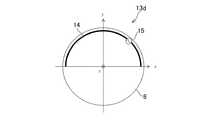
図7は、本発明の実施形態のさらなる一例として示す弧状のダイポールアンテナ13eの平面形状を示す図である。ダイポールアンテナ13eのアンテナ線14は、先のダイポールアンテナ13dよりも延長されており、3/4円周、すなわち、270°にわたって設けられている。給電点15はアンテナ線14の中間点からx方向に1/8円周偏った位置に設けられており、給電点15からのアンテナ線14の長さは、x方向側は1/4円周、−x方向は1/2円周となっている。この例でもダイポールアンテナ13dは、風防ガラス8の下面に設けられている。 FIG. 7 is a diagram showing a planar shape of an arc-shaped
図8Aは、図7に示したダイポールアンテナ13eの感度指向特性を示す図である。ダイポールアンテナ13eの感度指向特性は、やはり、上下対称の8の字形状を示すが、先のダイポールアンテナ13dよりさらに先鋭化しており、上下方向への指向特性がさらに鋭くなっている。そのため、上方向への受信感度はさらに向上している。また、先のダイポールアンテナ13dと同様に、右旋円偏波と左旋円偏波それぞれに対する感度指向特性が異なる。 FIG. 8A is a diagram showing sensitivity directivity characteristics of the
図8Bは、図7に示したダイポールアンテナ13eの右旋円偏波と左旋円偏波それぞれに対する感度指向特性を示す図である。ここでも、実線は右旋円偏波に対する感度指向特性、破線は左旋円偏波に対する感度指向特性である。 FIG. 8B is a diagram showing sensitivity directivity characteristics of the
ダイポールアンテナ13dの右旋円偏波に対する感度指向特性と左旋円偏波に対する感度指向特性の傾向は、先のダイポールアンテナ13dについてのものとおおむね同じであるが、メインローブ、サブローブ共にそれぞれより先鋭化し、指向性が強まっている。そのため、この例のダイポールアンテナ13eの方が、より上側についての受信感度が高いものとなっている。特に、右旋円偏波については、z方向に対してやや傾いているものの、上側に対して鋭い受信感度特性を持っていることから、上方から入射する右旋円偏波に対する受信感度が向上していることが分かる。 The tendency of the sensitivity directional characteristic for the right-handed circularly polarized wave and the sensitivity directional characteristic for the left-handed circularly polarized wave of the
以上説明した通り、誘電体である風防ガラス8の下面の外周縁に、全周とならない弧状にアンテナ線14を形成し、さらにその弧の中間点からいずれかの端部に偏った位置に給電点15を設けることにより、ダイポールアンテナ13の受信感度特性を上方に指向させることができ、受信感度が向上すると考えられる。特に、特定方向の円偏波に対しては、その効果が大きい。そして、アンテナ線14の長さや給電点15の位置は、受信感度特性の指向性に影響を及ぼすが、これらは受信しようとする電波の波長との兼ね合いで制限を受けるため、当該電波の周波数にて共振するよう設計する必要がある。 As described above, the
また、携帯型電波時計100が受信しようとするUHF帯等の高周波帯の電波は、アンテナの近傍に金属などの導電性の部材が存在していると利得が減少し、受信感度が低下する現象が起こる。そのため、本実施形態で例示している腕時計のように、時計の種々の機構をコンパクトにまとめると、アンテナと他の部材との配置関係により受信感度が変化することが観察される。 In addition, a radio wave in a high frequency band such as the UHF band that the
そこで、本実施形態に係る携帯型電波時計100では、ダイポールアンテナ13と、その利得に影響を与える主要な部材との位置関係を、可能な限りダイポールアンテナ13の利得に悪影響を与えないような配置としている。 Therefore, in the portable radio-controlled
この時、前述の通り、本実施形態に係る携帯型電波時計100のダイポールアンテナ13は、全周とならない弧状に形成されたアンテナ線14を有しているため、かかる形状を利用し、その弧の切欠き部に受信感度に影響を与えやすい部材を配置することで、ダイポールアンテナ13への導電性の部材による受信感度への影響を小さく抑えることができる。また、ダイポールアンテナ13は、アンテナ線14の途中に給電点15が配置されるため、給電点15と金属製の部材との配置関係も重要である。 At this time, as described above, the
まず、受信感度に影響を与えやすい大型の金属部材として、巻真12については、図1に示すように、上面から見て、アンテナ線14の弧の切欠き部に配置されるようにする。一般的な腕時計では、巻真12は3時の位置に配置されるため、アンテナ線14の弧の切欠き部が3時の位置を跨ぐようにアンテナ線14を配置すればよく、この例では1時半から4時半にかけて切欠き部となっているため、アンテナ線14と巻真12が上面から見て重ならない。なお、ダミー線16と巻真12は上側から見て重なり合うが、ダミー線16はダイポールアンテナ13としての機能はないため、このことは受信感度に影響を及ぼさない。 First, as a large metal member that easily affects the reception sensitivity, the winding
続いて、ソーラーセルとの接続部についても、上面から見て、アンテナ線14の弧の切欠き部に配置されるようにする。図9は、図1のIX−IX線による概略断面図である。携帯型電波時計100は、ベゼル9と胴18及び裏蓋19からなる外装ケース1の上面側に、風防ガラス8が取り付けられ、風防ガラス8の周縁の下面には、ダミー線16の断面が見えている。外装ケース1内には、ムーブメント20と、その上面に順に、ソーラーセル21、文字板2が重ねて配置されている。ソーラーセル21と文字板2の周縁部には、見返しリング17が配置され、両部材が直接外装ケース1に接触しないようにされているとともに、その周縁が見返しリング17の斜面で覆いかくされて、携帯型電波時計100の装飾性を高めている。ソーラーセル21と文字板2は、見返しリング17を介してベゼルの内面へ突出した部分により上側から押さえられ、ムーブメント20から浮き上がることがないように固定されている。 Subsequently, the connection portion with the solar cell is also arranged in the cutout portion of the arc of the
ムーブメント20の断面の詳細は省略するが、回路基板22のみ断面を図示した。半透過性を有する文字板2を通過してソーラーセル21に入射した光によって発電された電力は、ムーブメント20の回路基板22へと伝達されて消費電力の負担や、二次電池の充電に使用されるため、ソーラーセル21と回路基板22とは電気的に接続されなければならない。そのソーラーセル21と回路基板22とを電気的に接続する構成を接続部23と呼ぶと、図9にはかかる接続部23が示されている。 Although details of the cross section of the
ここで、本実施形態では、接続部23は弾性を有する金属部材であるバネを用いてソーラーセル21と回路基板22とを接続するようにしている。接続部23の具体的な構造は特に限定されるものではないが、ここで示したようなバネなど、比較的大きな金属部材が使用されることがあり、したがって、ソーラーセル21との接続部23を、上面から見て、アンテナ線14の弧の切欠き部に配置することにより、受信感度への影響を小さく抑えることができる。本実施形態では、図1に示されるように、接続部23は、3時半の位置に設けられている。 Here, in this embodiment, the
さらに、受信中を示す指針についても、上面から見て、アンテナ線14の弧の切欠き部に配置されるようにする。本実施形態では、受信中や、受信結果等の携帯型電波時計100の状態を示す指針として、秒針を使用しており、また、秒針が受信中を指し示す「RX」の表示は、図1に示すように、2時半の位置に設けられている。 Further, the pointer indicating that the signal is being received is also arranged in the cutout portion of the arc of the
図10は、携帯型電波時計100が受信動作中を示している図である。同図に示したように、時刻針3の秒針が2時半の位置にある「RX」を指し示しているが、このとき、秒針の先端はアンテナ線14の弧の切欠き部に配置されたダミー線16の近傍に位置しており、アンテナ線14には近づかない。そのため、秒針が金属などの導電性の部材であったとしても、受信中における受信感度への影響を小さく抑えることができる。なお、時刻針3の残る時針と分針については、本実施形態では秒針ほどの長さがなく、ダイポールアンテナ13の受信感度への影響は限定的なものにとどまる。 FIG. 10 is a diagram showing the
なお、受信中を示す指針の配置は、アンテナ線14の弧の切欠き部の範囲内であればよく、さらに、当該指針がアンテナ線14から最も遠ざかる位置となる、弧の切欠き部の中心を向く配置とすることがより好ましい。この実施形態では、かかる位置は3時の位置となるが、図10では、当該指針である秒針が、他の時字等でなく、「RX」の表示を示していることをわかりやすく図示する都合上、2時半の位置に「RX」の表示を示した。 Note that the position of the pointer indicating reception may be within the range of the notch of the arc of the
以上説明した巻真12、ソーラーセルとの接続部23及び、受信中を示す指針以外にも、巻真12に連なる金属製の歯車や、電池もダイポールアンテナ13の受信感度へと影響を及ぼし得る部材であるから、こうした大型の金属部材も、上面から見て、アンテナ線14からできるだけ遠ざけて配置されることが望ましく、アンテナ線14の弧の切欠き部の範囲内に配置されることがより望ましい。 In addition to the winding
また、給電点15と他の部材との位置関係として、給電点15は外部からの電気的影響を受けやすいため、受信感度に影響を及ぼすと考えられる導電製部材から距離をおいて配置することが望ましい。そして、装飾性の観点から、文字板2の上側に設けられる時字6を金属製とする場合があるが、一般に時字6は文字板2の外周に配置されるため、風防ガラス8の周縁の下面に配置されるアンテナ線14と時字6は比較的近い配置となる。 Also, as the positional relationship between the
そこで、図1に示すように、給電点15は、隣接する時字6と時字6の間の位置、すなわち、ここで示した例では10時半の位置に設けられ、時字6及び、その径方向外側領域と上面から見て重ならない位置に設けている。このようにすることで、導電性の時字6による受信感度への影響を小さく抑えている。 Therefore, as shown in FIG. 1, the
もちろん、図10に示したように、受信中を示す時刻針3である秒針及び、その径方向外側領域はアンテナ線14と重ならず、当然に給電点15とも重なることはない。 Of course, as shown in FIG. 10, the second hand, which is the time hand 3 indicating reception, and the radially outer region thereof do not overlap with the
さらに、給電点15は、上面から見て、文字板2上に設けられた特定の2の金属性装飾部材の中間位置の方向と重なるように設けられることが望ましい。ここでいう特定の金属性装飾部材は、同種の装飾部材を指しており、例えば、先ほどあげた時字6が該当する。そして、給電点15は、2の時字である、10時位置の時字6と11時位置の時字6の中間位置となる10時半の方向に設けられているから、この2の時字6から互いに離れた位置に設けられていることとなる。また、副針4の周囲に設けられた環状の装飾部材5もここでいう金属性装飾部材に該当する。そして、隣接する2の装飾部材5として、12時方向のものと、9時方向のものが設けられており、その中間位置はやはり10時半方向となるから、給電点15は、2の装飾部材5の中間位置の方向と重なるように設けられていることになる。なお、ここでいう中間位置の方向とは、携帯型電波時計100の中心(通常、これは時刻針3の回転中心に一致する)から中間位置の向かって引いた直線上を指している。 Furthermore, it is desirable that the
なお、本実施形態で示した給電点の位置は一例であり、必ずしも10時半の位置でなければならないわけではない。上述したように、アンテナ線14の弧の切欠き部が巻真12を避けるように配置されると、巻真12は通常3時の方向に配置されるため、アンテナ線14の中間位置は、概ね9時の位置又はその近傍となりやすい。したがって、ダイポールアンテナ13が右旋円偏波の受信感度を高めたものである場合には、給電点はおおむね9時から1時の間に配置されることが好ましく、より好ましくは9時から12時の間に配置される。ダイポールアンテナ13が左旋円偏波の受信感度を高めたものである場合には、この位置関係は逆となり、給電点はおおむね5時から9時の間に配置されることが好ましく、より好ましくは6時から8時の間に配置される。 In addition, the position of the feeding point shown in the present embodiment is an example, and the position does not necessarily have to be at 10:30. As described above, when the notch of the arc of the
また、図1に示すように、受信結果として、秒針が受信失敗を示す「NG」の表示は、給電点15と同じ10時半の方向に設けられており、携帯型電波時計100が受信を行い、時刻情報の取得に失敗した場合には時刻針3の秒針がこの位置を指し示すことになる。図11は、携帯型電波時計100が受信結果を示している一例の図である。このように、受信結果を示す時刻針3である秒針が給電点15と同じ向きを指し示しており、給電点15は上面から見て受信結果を示す秒針の径方向外側領域に重なる位置に設けられていることとなるが、受信結果を示す段階では、ダイポールアンテナ13による電波の受信はすでに終了しているため、特段の問題は生じない。 Further, as shown in FIG. 1, as the reception result, “NG” indicating that the second hand indicates reception failure is provided in the same direction of 10:30 as the
以上説明した実施形態に係る携帯型電波時計100では、図1に示したように、上側から風防ガラス8の下面に形成されたアンテナ線14が視認でき、ダミー線16を配置することで、ダイポールアンテナ13を時計のデザインとして取り込んでいるが、ダイポールアンテナ13を目隠しにより隠す構成も可能である。 In the
図12は、本発明の第2の実施形態に係る携帯型電波時計200を示す上面図である。なお、本実施形態は、先の第1の実施形態と同一の部材については同符号を付し、その重複する説明は省略するものとする。 FIG. 12 is a top view showing a portable radio timepiece 200 according to the second embodiment of the present invention. In the present embodiment, the same members as those in the first embodiment are denoted by the same reference numerals, and redundant description thereof will be omitted.
図12に示すように、本実施形態では、風防ガラス8の周縁の下面に設けられたダイポールアンテナ13は上側からは見えず、その代わりに、風防ガラス8の周縁の下面に環状の帯状に設けられた目隠し24が見えている。
図13は、本発明の第2の実施形態に係る風防ガラス8の下面図である。風防ガラス8の下面の周縁には、環状に帯状の目隠し24が設けられ、さらにその目隠し24の幅内に収まるように、ダイポールアンテナ13のアンテナ線14と給電点15が設けられている。このように、ダイポールアンテナ13を目隠し24の下面に設けて上側から見えなくすることで、デザインの自由度を高めることができる。As shown in FIG. 12, in this embodiment, the
FIG. 13 is a bottom view of the
また、アンテナ線14の弧の切欠き部は、目隠し24により上側から視認することはできないから、本実施形態では、先の実施形態で設けていたダミー線16は不要である。 In addition, since the notch portion of the arc of the
目隠し24の材質は、ダイポールアンテナ13による電波の受信を阻害しないものであれば特に限定されず、又、その作成方法も任意である。例えば、目隠し24は、印刷により形成された有色の塗膜であってよい。あるいは、環状の合成樹脂製のフィルムを張り付けることにより目隠し24を形成してもよい。 The material of the blindfold 24 is not particularly limited as long as it does not hinder the reception of radio waves by the
さらに、目隠し24を、環状の誘電体膜により構成してよい。この場合、風防ガラス8と、アンテナ線14との間に環状の誘電体膜が目隠し24として設けられることになる。この誘電体膜の誘電率は大きいものであることが望ましく、好ましくは高誘電体とし、少なくとも、風防ガラス8よりも誘電率の大きい材質を選択する。このようにアンテナ線14と密着して誘電体膜を設けることにより、波長短縮効果が見込め、ダイポールアンテナ13自体を小さく形成することができる。かかる誘電体膜は、あらかじめ環状に形成したものを風防ガラス8に貼りつけることにより形成してもよいし、スパッタリングやイオンプレーティング等の薄膜形成方法により形成してもよい。 Further, the blindfold 24 may be constituted by an annular dielectric film. In this case, an annular dielectric film is provided as a blindfold 24 between the
さらに、図14に示すように、給電点15の下面に凹となる導電性の受け部26を形成してもよい。同図は、給電点15に弾性ピン25が接触している様子を示す模式図である。図14は、アンテナ線14に沿った周方向の部分断面を示している。図中示されているように、風防ガラス8の下面に形成されたアンテナ線14の途中、給電点15のアンテナ線が太くなっている部分において、下側に凸となる導電性の受け部26が形成されている。そして、受け部26に下側から、弾性ピン25が接触して導通が取られている。 Further, as shown in FIG. 14, a conductive receiving
ここで、弾性ピン25は、その長手方向に弾性的に伸縮する導電性のピンであり、アンテナ線14の給電点15とムーブメント20の回路基板22とを電気的に接続するための部品である。そして、受け部26が下側に凹形状を有していることで、自動調心作用が働き、弾性ピン25の受け部26との接触位置は、受け部26の凹形状の中央へと導かれる。 Here, the
このようにすることで、携帯型電波時計100の組立時の、弾性ピン25と給電点15との接触ミスによる不良の発生や、携帯型電波時計100に外部から衝撃が加わった際に、弾性ピン25の位置がずれて接触不良を起こす可能性が低減される。 In this way, when the
なお、図14に示した弾性ピンと給電点15との接触の構造は、以上で示した第1及び第2の実施形態のように、アンテナ線14の弧の中間点からいずれかの端部に偏った位置に給電点15を設ける構成にのみに限定されて適用されるべきものではなく、アンテナ線14の弧の中間点に給電点15が設けられた構造のアンテナに適用することも可能である。 Note that the structure of contact between the elastic pin and the
以上説明した実施形態においては、アンテナ線14は風防ガラス8の下面に形成された構成であるとして説明を行ったが、これに限定されない。すなわち、右旋円偏波又は左旋円偏波のうち、一方の円偏波成分に対する受信感度を向上するためには、風防ガラス8の外周縁に沿うようにアンテナが設けられ、そのアンテナが誘電体に接している構成であればよい。 In the embodiment described above, the
例えば、非導電性部材である見返しリング17の上面(風防ガラス8側の面)に弧状のアンテナ線14を、見返しリング17の下面(裏面)に給電点15をそれぞれ形成し、ダイポール素子長が互いに異なるような構成とし、アンテナ線14と風防ガラス8とが接するように配置した構成とすることができる。このような構成により、風防ガラス8にアンテナ線14を形成したときと同様に、一方の円偏波成分に対する受信感度を向上する効果を得ることができる。 For example, an
このとき、見返しリング17を風防ガラス8側に付勢するバネなどの付勢部材をさらに有することにより、アンテナ線14と風防ガラス8との密着性を高めることができる。さらに、見返しリング17とは別体であって、非導電性部材である基板にアンテナ線14及び給電点15を形成したアンテナ体を見返しリング17の上面側であって風防ガラス8に接するように配置する構成としてもよい。 At this time, the adhesiveness between the
以上説明した実施形態に示した具体的な構成は例示として示したものであり、本明細書にて開示される発明をこれら具体例の構成そのものに限定するものではない。当業者はこれら開示された実施形態に種々の変形、例えば、各部材あるいはその部分の形状や数、配置等を適宜変更したり、例示された実施形態を互いに組み合わせたりしてもよい。本明細書にて開示される発明の技術的範囲は、そのようになされた変形をも含むものと理解すべきである。 The specific configurations shown in the embodiments described above are shown as examples, and the invention disclosed in this specification is not limited to the configurations of these specific examples. Those skilled in the art may make various modifications to the disclosed embodiments, for example, appropriately change the shape, number, arrangement, etc. of each member or part thereof, or combine the illustrated embodiments with each other. It should be understood that the technical scope of the invention disclosed herein includes such modifications.
100,200 携帯型電波時計、1 外装ケース、2 文字板、3 時刻針、4 副針、5 装飾部材、6 時字、7 日窓、8 風防ガラス、9 ベゼル、10 竜頭、11 プッシュボタン、12 巻真、13 ダイポールアンテナ、14 アンテナ線、15 給電点、16 ダミー線、17 見返しリング、18 胴、19 裏蓋、20 ムーブメント、21 ソーラーセル、22 回路基板、23 接続部、24 目隠し、25 弾性ピン、26 受け部。 100,200 Portable radio timepiece, 1 exterior case, 2 dial, 3 time hand, 4 secondary hand, 5 decorative member, 6 hour, 7 daylight, 8 windshield, 9 bezel, 10 crown, 11 push button, 12 winding stem, 13 dipole antenna, 14 antenna wire, 15 feeding point, 16 dummy wire, 17 turn ring, 18 body, 19 back cover, 20 movement, 21 solar cell, 22 circuit board, 23 connection part, 24 blindfold, 25 Elastic pin, 26 receiving part.
Claims (9)
Translated fromJapanese前記風防ガラスの下面側であって、前記風防ガラスの外周縁に沿って弧状に設けられたアンテナ線と、前記アンテナ線の弧の中間点からいずれかの端部に偏った位置に設けられた給電点を有するダイポールアンテナと、
前記アンテナ線に接する誘電体と、
を有する携帯型電波時計。Windshield,
On the lower surface side of the windshield glass, the antenna wire provided in an arc shape along the outer peripheral edge of the windshield glass, and provided at a position biased to either end from the midpoint of the arc of the antenna wire A dipole antenna having a feed point;
A dielectric in contact with the antenna wire;
A portable radio-controlled timepiece.
前記アンテナ線は、前記風防ガラスの下面に配置される請求項1に記載の携帯型電波時計。The dielectric is the windshield,
The portable radio timepiece according to claim 1, wherein the antenna wire is disposed on a lower surface of the windshield.
(a)巻真。
(b)ソーラーセルとの接続部。
(c)受信中を示す指針。
(d)巻真に連なる金属製歯車。
(e)電池。The portable radio timepiece according to any one of claims 1 to 5, wherein at least one of the following is arranged in a notch portion of the arc of the antenna wire as viewed from above.
(A) winding true.
(B) Connection part with solar cell.
(C) A guideline indicating reception.
(D) A metal gear connected to the winding stem.
(E) Battery.
(d)文字板上に設けられた金属製時字及びその径方向外側領域。
(e)受信中を示す指針及びその径方向外側領域。The portable radio timepiece according to any one of claims 1 to 6, wherein the feeding point is provided at a position that does not overlap with at least one of the following when viewed from above.
(D) Metal time letters provided on the dial and their radially outer regions.
(E) A pointer indicating that data is being received and a radially outer region thereof.
(f)文字板上に設けられた特定の2の金属性装飾部材の中間位置の方向。
(g)受信結果を示す指針又はその径方向外側領域。The portable radio timepiece according to claim 7, wherein the feeding point is provided at a position overlapping with at least one of the following when viewed from above.
(F) The direction of the intermediate position of the specific two metallic decorative members provided on the dial.
(G) A pointer indicating a reception result or a radially outer region thereof.
前記受け部に下面側から接触する弾性ピンと、
を有する請求項1〜8のいずれか1項に記載の携帯型電波時計。A conductive receiving portion formed at the feeding point and recessed downward;
An elastic pin in contact with the receiving part from the lower surface side;
The portable radio timepiece according to claim 1, comprising:
Priority Applications (1)
| Application Number | Priority Date | Filing Date | Title |
|---|---|---|---|
| JP2016223029AJP6803206B2 (en) | 2016-11-16 | 2016-11-16 | Portable radio clock |
Applications Claiming Priority (1)
| Application Number | Priority Date | Filing Date | Title |
|---|---|---|---|
| JP2016223029AJP6803206B2 (en) | 2016-11-16 | 2016-11-16 | Portable radio clock |
Publications (2)
| Publication Number | Publication Date |
|---|---|
| JP2018080991Atrue JP2018080991A (en) | 2018-05-24 |
| JP6803206B2 JP6803206B2 (en) | 2020-12-23 |
Family
ID=62198744
Family Applications (1)
| Application Number | Title | Priority Date | Filing Date |
|---|---|---|---|
| JP2016223029AActiveJP6803206B2 (en) | 2016-11-16 | 2016-11-16 | Portable radio clock |
Country Status (1)
| Country | Link |
|---|---|
| JP (1) | JP6803206B2 (en) |
Citations (11)
| Publication number | Priority date | Publication date | Assignee | Title |
|---|---|---|---|---|
| JP2000059241A (en)* | 1998-08-07 | 2000-02-25 | Nippon Antenna Co Ltd | Small receiver |
| JP2003315475A (en)* | 2002-04-24 | 2003-11-06 | Seiko Epson Corp | Timepiece |
| JP2008211719A (en)* | 2007-02-28 | 2008-09-11 | Seiko Epson Corp | Electronics |
| JP2010085312A (en)* | 2008-10-01 | 2010-04-15 | Casio Computer Co Ltd | Electronic equipment |
| JP2011097431A (en)* | 2009-10-30 | 2011-05-12 | Seiko Epson Corp | Arm-mounted electronic apparatus |
| JP2013050360A (en)* | 2011-08-30 | 2013-03-14 | Seiko Epson Corp | Electronic timepiece with built-in antenna |
| JP2014062843A (en)* | 2012-09-24 | 2014-04-10 | Seiko Epson Corp | Built-in antenna electronic clock |
| JP2014062866A (en)* | 2012-09-24 | 2014-04-10 | Seiko Epson Corp | Built-in antenna electronic clock |
| JP2015143664A (en)* | 2014-01-31 | 2015-08-06 | セイコーエプソン株式会社 | Electronic clock |
| JP2015175805A (en)* | 2014-03-18 | 2015-10-05 | カシオ計算機株式会社 | Electronics |
| JP2016121990A (en)* | 2014-12-25 | 2016-07-07 | シチズンホールディングス株式会社 | Electronic equipment |
- 2016
- 2016-11-16JPJP2016223029Apatent/JP6803206B2/enactiveActive
Patent Citations (11)
| Publication number | Priority date | Publication date | Assignee | Title |
|---|---|---|---|---|
| JP2000059241A (en)* | 1998-08-07 | 2000-02-25 | Nippon Antenna Co Ltd | Small receiver |
| JP2003315475A (en)* | 2002-04-24 | 2003-11-06 | Seiko Epson Corp | Timepiece |
| JP2008211719A (en)* | 2007-02-28 | 2008-09-11 | Seiko Epson Corp | Electronics |
| JP2010085312A (en)* | 2008-10-01 | 2010-04-15 | Casio Computer Co Ltd | Electronic equipment |
| JP2011097431A (en)* | 2009-10-30 | 2011-05-12 | Seiko Epson Corp | Arm-mounted electronic apparatus |
| JP2013050360A (en)* | 2011-08-30 | 2013-03-14 | Seiko Epson Corp | Electronic timepiece with built-in antenna |
| JP2014062843A (en)* | 2012-09-24 | 2014-04-10 | Seiko Epson Corp | Built-in antenna electronic clock |
| JP2014062866A (en)* | 2012-09-24 | 2014-04-10 | Seiko Epson Corp | Built-in antenna electronic clock |
| JP2015143664A (en)* | 2014-01-31 | 2015-08-06 | セイコーエプソン株式会社 | Electronic clock |
| JP2015175805A (en)* | 2014-03-18 | 2015-10-05 | カシオ計算機株式会社 | Electronics |
| JP2016121990A (en)* | 2014-12-25 | 2016-07-07 | シチズンホールディングス株式会社 | Electronic equipment |
Also Published As
| Publication number | Publication date |
|---|---|
| JP6803206B2 (en) | 2020-12-23 |
Similar Documents
| Publication | Publication Date | Title |
|---|---|---|
| US9869975B2 (en) | Electronic timepiece | |
| US11150612B2 (en) | Portable radio-controlled watch | |
| JP5493527B2 (en) | Clock with wireless function | |
| CN104155872B (en) | Timepiece with a wireless function | |
| US10446924B2 (en) | Electronic timepiece | |
| JP6808914B2 (en) | Electronic clock and antenna device | |
| JP7073833B2 (en) | Electronic clock | |
| JP6763415B2 (en) | Solar panels, display devices and clocks | |
| JP6901945B2 (en) | Portable radio clock | |
| CN110286581A (en) | electronic clock | |
| JP5741734B2 (en) | Clock with wireless function | |
| JP6883015B2 (en) | Radio watch | |
| JP2018169189A (en) | Radio-controlled timepiece | |
| JP6803206B2 (en) | Portable radio clock | |
| JP2017122659A (en) | Electronic watch | |
| JP2021047144A (en) | Electronic clock with built-in antenna | |
| JP7022654B2 (en) | Radio clock | |
| JP2008039716A (en) | Portable electronic device | |
| JP2019132684A (en) | Atomic clock | |
| JP2019039889A (en) | Portable radio clock | |
| JP2023090634A (en) | electronic watch | |
| JP2023140583A (en) | Electronic watch | |
| JP2015172544A (en) | Electric wave wrist watch | |
| JP2017083228A (en) | Radio-controlled wrist watch |
Legal Events
| Date | Code | Title | Description |
|---|---|---|---|
| A621 | Written request for application examination | Free format text:JAPANESE INTERMEDIATE CODE: A621 Effective date:20190607 | |
| A977 | Report on retrieval | Free format text:JAPANESE INTERMEDIATE CODE: A971007 Effective date:20200616 | |
| A131 | Notification of reasons for refusal | Free format text:JAPANESE INTERMEDIATE CODE: A131 Effective date:20200630 | |
| A521 | Request for written amendment filed | Free format text:JAPANESE INTERMEDIATE CODE: A523 Effective date:20200825 | |
| A131 | Notification of reasons for refusal | Free format text:JAPANESE INTERMEDIATE CODE: A131 Effective date:20200915 | |
| A521 | Request for written amendment filed | Free format text:JAPANESE INTERMEDIATE CODE: A523 Effective date:20201021 | |
| TRDD | Decision of grant or rejection written | ||
| A01 | Written decision to grant a patent or to grant a registration (utility model) | Free format text:JAPANESE INTERMEDIATE CODE: A01 Effective date:20201104 | |
| A61 | First payment of annual fees (during grant procedure) | Free format text:JAPANESE INTERMEDIATE CODE: A61 Effective date:20201130 | |
| R150 | Certificate of patent or registration of utility model | Ref document number:6803206 Country of ref document:JP Free format text:JAPANESE INTERMEDIATE CODE: R150 | |
| R250 | Receipt of annual fees | Free format text:JAPANESE INTERMEDIATE CODE: R250 |