Movatterモバイル変換


[0]ホーム

URL:


JP2018080653A - Fluid machinery - Google Patents

Fluid machinery
Download PDF

Info

Publication number
JP2018080653A
JP2018080653AJP2016224051AJP2016224051AJP2018080653AJP 2018080653 AJP2018080653 AJP 2018080653AJP 2016224051 AJP2016224051 AJP 2016224051AJP 2016224051 AJP2016224051 AJP 2016224051AJP 2018080653 AJP2018080653 AJP 2018080653A
Authority
JP
Japan
Prior art keywords
blade
impeller
diffuser
hub
height direction
Prior art date
Legal status (The legal status is an assumption and is not a legal conclusion. Google has not performed a legal analysis and makes no representation as to the accuracy of the status listed.)
Granted
Application number
JP2016224051A
Other languages
Japanese (ja)
Other versions
JP6785623B2 (en
Inventor
和寛 塚本
Kazuhiro Tsukamoto
和寛 塚本
澄賢 平舘
Kiyotaka HIRADATE
澄賢 平舘
聖英 坂本
Kiyohide Sakamoto
聖英 坂本
泰 新川
Yasushi Shinkawa
泰 新川
毅 内山
Takeshi Uchiyama
毅 内山
Current Assignee (The listed assignees may be inaccurate. Google has not performed a legal analysis and makes no representation or warranty as to the accuracy of the list.)
Hitachi Ltd
Original Assignee
Hitachi Ltd
Priority date (The priority date is an assumption and is not a legal conclusion. Google has not performed a legal analysis and makes no representation as to the accuracy of the date listed.)
Filing date
Publication date
Application filed by Hitachi LtdfiledCriticalHitachi Ltd
Priority to JP2016224051ApriorityCriticalpatent/JP6785623B2/en
Publication of JP2018080653ApublicationCriticalpatent/JP2018080653A/en
Application grantedgrantedCritical
Publication of JP6785623B2publicationCriticalpatent/JP6785623B2/en
Activelegal-statusCriticalCurrent
Anticipated expirationlegal-statusCritical

Links

Images

Landscapes

Abstract

Translated fromJapanese

【課題】オープン型の羽根車を備える流体機械において、羽根付きディフューザにおける逆流をより抑制する。【解決手段】ディフューザの各々の翼は、基準となる翼型が翼高さ方向に、該翼高さ方向と垂直な平面内での移動を伴って積層された形状で形成されている。ここで、翼高さ方向と垂直な平面内における移動方向のうち、翼型の前縁と後縁とを結ぶ翼弦方向に垂直な方向の成分であって羽根車の回転方向と逆の方向に移動させることを正方向のダイヘドラル移動と呼ぶ。そして、翼高さ方向の位置とダイヘドラル量との関係を示す分布をダイヘドラル分布が、ハブ面からシュラウド面に向けて、増加し、一つの極大値Pを示した後、減少している。また、ダイヘドラル分布において極大値Pを示す位置は、翼の翼高さ方向の中央位置Mよりもハブ面側に設定されている。【選択図】図3In a fluid machine including an open impeller, backflow in a vaned diffuser is further suppressed. Each wing of the diffuser is formed in a shape in which a reference airfoil is stacked in the blade height direction with movement in a plane perpendicular to the blade height direction. Here, of the moving directions in a plane perpendicular to the blade height direction, the component is in the direction perpendicular to the chord direction connecting the leading edge and the trailing edge of the airfoil and is opposite to the rotational direction of the impeller This movement is called a positive dihedral movement. The distribution indicating the relationship between the position in the blade height direction and the amount of the dihedral amount increases from the hub surface to the shroud surface, and decreases after showing one maximum value P. Further, the position showing the maximum value P in the dihedral distribution is set closer to the hub surface than the center position M in the blade height direction. [Selection] Figure 3

Description

Translated fromJapanese

本発明は、羽根付きディフューザを備える流体機械に関する。  The present invention relates to a fluid machine including a vaned diffuser.

回転する遠心式羽根車を有する遠心式流体機械は、従来、様々なプラント、空調機器、液体圧送ポンプ、ターボチャージャ等において利用されている。近年の環境負荷低減要求の高まりを受けて、このような遠心式流体機械等の流体機械は、従来以上の高効率化と、高作動範囲化が求められている。  Centrifugal fluid machines having rotating centrifugal impellers are conventionally used in various plants, air conditioners, liquid pumps, turbochargers and the like. In response to increasing demands for reducing environmental loads in recent years, fluid machines such as centrifugal fluid machines are required to have higher efficiency and higher operating range than ever before.

遠心式流体機械の一種である単段の遠心ブロワでは、片持ちの軸に一つの羽根車が締結されており、その下流側にはディフューザとスクロールとが設けられていることが一般的である。ディフューザとしては、ベーンレスディフューザや羽根付きディフューザが、その用途や目的に応じて設置されている。  In a single-stage centrifugal blower which is a kind of centrifugal fluid machine, one impeller is fastened to a cantilever shaft, and a diffuser and a scroll are generally provided on the downstream side. . As the diffuser, a vaneless diffuser or a vaned diffuser is installed according to its use or purpose.

羽根付きディフューザの一種である小弦節比ディフューザは、ディフューザの翼の前縁において入り口角度に沿う線に垂直に引いた線が隣り合う翼と交差しない程度に翼が短い。このため、小弦節比ディフューザは、翼列部にスロートを有さないことを特徴とし、低流量域において二次流れによる翼面上の境界層掃き出し効果によって翼面剥離を防ぐので、作動範囲を確保したい場合に用いられることが多い。  A low-string ratio diffuser, which is a kind of vaned diffuser, has a wing that is short enough that the line drawn perpendicular to the line along the entrance angle at the leading edge of the wing of the diffuser does not intersect the adjacent wing. For this reason, the low chord joint ratio diffuser is characterized by having no throat in the cascade, and the blade surface separation is prevented by the boundary layer sweep-out effect on the blade surface due to the secondary flow in the low flow range, so the operating range Often used to secure

小弦節比ディフューザに代表される遠心式流体機械向けの羽根付きディフューザには、基準となる翼型を翼高さ方向(翼スパン方向)に平行に積層した二次元翼が一般的に用いられている。しかし、更なる性能改善の要求から、翼形状の三次元化が行われている。  A bladed diffuser for centrifugal fluid machines represented by a low chord joint ratio diffuser generally uses a two-dimensional blade in which a reference airfoil is stacked parallel to the blade height direction (blade span direction). ing. However, the blade shape has been made three-dimensional due to the demand for further performance improvement.

例えば特許文献1には、ディフューザの翼を規定するために基準となる翼型を翼高さ方向に積層する際、翼型を羽根車の回転方向に対して順方向や逆方向に移動させながら積層する技術が開示されている。これにより、翼高さ方向に形成される圧力面、負圧面が、自由曲面によって表現される。  For example, inPatent Document 1, when stacking the airfoil as a reference in order to define the wings of the diffuser in the blade height direction, the airfoil is moved in the forward or reverse direction with respect to the rotation direction of the impeller. A technique for laminating is disclosed. Thereby, the pressure surface and the suction surface formed in the blade height direction are expressed by a free-form surface.

特開2012−122443号公報JP 2012-122443 A

特許文献1に記載のディフューザは、翼の圧力面、負圧面を自由曲面によって表現することによって、翼から流体へと作用する翼力の向きを制御し、二次流れの発達を抑制することを特徴としている。そして、この特許文献1に記載のディフューザの翼の形状は、ハブ板とシュラウド板との間に羽根が設けられたクローズド型の羽根車を備える流体機械に適用されている。  The diffuser described inPatent Document 1 controls the direction of the blade force acting from the blade to the fluid by expressing the pressure surface and suction surface of the blade by a free-form surface, and suppresses the development of the secondary flow. It is a feature. And the shape of the wing | blade of a diffuser described in thispatent document 1 is applied to the fluid machine provided with the closed type impeller by which the blade | wing was provided between the hub board and the shroud board.

一方、シュラウド板を有しないオープン型の羽根車を備える流体機械は、羽根車のシュラウド面側に発達する翼端漏れ流れの存在がディフューザにおける流れに影響を及ぼす点で、クローズド型の羽根車を備える流体機械と異なっている。このため、特許文献1に記載のディフューザの翼の形状は、オープン型の羽根車を備える流体機械のディフューザにおいて生じる逆流を十分に抑制できるものではなかった。  On the other hand, a fluid machine equipped with an open type impeller without a shroud plate uses a closed type impeller in that the presence of a tip leakage flow that develops on the shroud surface side of the impeller affects the flow in the diffuser. It differs from the fluid machine provided. For this reason, the shape of the wing | blade of a diffuser described inpatent document 1 was not able to fully suppress the backflow produced in the diffuser of a fluid machine provided with an open type impeller.

本発明は、前記した事情に鑑みなされたものであり、オープン型の羽根車を備える流体機械において、羽根付きディフューザにおける逆流をより抑制することを課題とする。  This invention is made | formed in view of an above described situation, and makes it a subject to suppress more the backflow in a diffuser with a blade | wing in a fluid machine provided with an open type impeller.

上記課題を達成すべく、本発明に係る流体機械は、円管形状をなすハブ板、および前記ハブ板の外周面に配置されている複数の羽根を有するオープン型の羽根車と、前記羽根車の下流に配置されている羽根付きディフューザと、を備え、前記羽根付きディフューザは、前記羽根車の下流側においてハブ面とシュラウド面との間に形成された流路中に周方向に間隔をあけて配置された複数の翼を有しており、各々の前記翼は、基準となる翼型が前記羽根車の回転軸の軸方向である翼高さ方向に、該翼高さ方向と垂直な平面内での移動を伴って積層された形状で形成されており、前記翼高さ方向と垂直な平面内における移動方向のうち、基準となる翼型の前縁と後縁とを結ぶ翼弦方向に垂直な方向の成分であって羽根車の回転方向と逆の方向に移動させることを正方向の移動とするダイヘドラル分布が、前記ハブ面から前記シュラウド面に向けて、増加し、一つの極大値を示した後、減少しており、前記極大値を示す位置は、前記翼の翼高さ方向の中央位置よりも前記ハブ面側に設定されていることを特徴とする。  In order to achieve the above object, a fluid machine according to the present invention includes a hub plate having a circular tube shape, an open impeller having a plurality of blades disposed on an outer peripheral surface of the hub plate, and the impeller. A vaned diffuser disposed downstream of the impeller, wherein the vaned diffuser is spaced circumferentially in a flow path formed between the hub surface and the shroud surface downstream of the impeller. Each of the blades is perpendicular to the blade height direction in the blade height direction in which the reference airfoil is the axial direction of the rotating shaft of the impeller. A chord that is formed in a stacked shape with movement in a plane and connects the leading and trailing edges of the reference airfoil out of the movement directions in a plane perpendicular to the blade height direction. Component in the direction perpendicular to the direction and shifted in the direction opposite to the rotation direction of the impeller. The dihedral distribution having a positive movement is increased from the hub surface toward the shroud surface, and after showing one maximum value, the dihedral distribution decreases, and the position showing the maximum value is It is characterized in that it is set closer to the hub surface than the center position in the blade height direction of the blade.

本発明によれば、オープン型の羽根車を備える流体機械において、羽根付きディフューザにおける逆流をより抑制することができる。  ADVANTAGE OF THE INVENTION According to this invention, in the fluid machine provided with an open-type impeller, the backflow in a diffuser with a blade | wing can be suppressed more.

本発明の一実施形態に係る流体機械を示す子午面断面図である。It is a meridian plane sectional view showing a fluid machine concerning one embodiment of the present invention.基準となる翼型を積層することによって翼の形状を規定する方法を説明するための図である。It is a figure for demonstrating the method of prescribing the shape of a wing | blade by laminating | stacking the reference | standard airfoil.ディフューザの翼のダイヘドラル分布の一例を示す図である。It is a figure which shows an example of the dihedral distribution of the wing | blade of a diffuser.従来の比較例に係るディフューザの翼の外観を示す図である。It is a figure which shows the external appearance of the wing | blade of the diffuser which concerns on the conventional comparative example.本実施形態に係るディフューザの翼の外観を示す図である。It is a figure which shows the external appearance of the wing | blade of the diffuser which concerns on this embodiment.図6(a)は、比較例に係るディフューザにおける設計点の流量時での流れを模式的に示す子午面断面図である。図6(b)は、本実施形態に係るディフューザにおける設計点の流量時での流れを模式的に示す子午面断面図である。FIG. 6A is a meridional cross-sectional view schematically showing the flow at the design point flow rate in the diffuser according to the comparative example. FIG. 6B is a meridional cross-sectional view schematically showing the flow at the design point flow rate in the diffuser according to the present embodiment.図7(a)は、比較例に係るディフューザにおける非設計点の流量時での流れを模式的に示す子午面断面図である。図7(b)は、本実施形態に係るディフューザにおける非設計点の流量時での流れを模式的に示す子午面断面図である。FIG. 7A is a meridional cross-sectional view schematically showing a flow at a non-design point flow rate in the diffuser according to the comparative example. FIG. 7B is a meridional cross-sectional view schematically showing the flow at the flow rate of the non-design point in the diffuser according to the present embodiment.従来の比較例に係るディフューザを搭載した流体機械と、本実施形態に係るディフューザを搭載した流体機械との性能を比較したグラフである。It is the graph which compared the performance of the fluid machine carrying the diffuser which concerns on the conventional comparative example, and the fluid machine carrying the diffuser which concerns on this embodiment.図9(a)は、従来の比較例に係るディフューザを搭載した流体機械における数値解析によって得られたディフューザ周囲の流れ場の一例を模式的に示す図である。図9(b)は、本実施形態に係るディフューザを搭載した流体機械における数値解析によって得られたディフューザ周囲の流れ場の一例を模式的に示す図である。Fig.9 (a) is a figure which shows typically an example of the flow field around a diffuser obtained by the numerical analysis in the fluid machine carrying the diffuser concerning the conventional comparative example. FIG. 9B is a diagram schematically illustrating an example of a flow field around the diffuser obtained by numerical analysis in the fluid machine equipped with the diffuser according to the present embodiment.

本発明の実施形態について、適宜図面を参照しながら詳細に説明する。
なお、各図において、共通する構成要素や同様な構成要素については、同一の符号を付し、それらの重複する説明を適宜省略する。
Embodiments of the present invention will be described in detail with reference to the drawings as appropriate.
In addition, in each figure, about the same component or the same component, the same code | symbol is attached | subjected and those overlapping description is abbreviate | omitted suitably.

図1は、本発明の一実施形態に係る流体機械100を示す子午面断面図である。子午面断面は、流体機械100を回転軸2の中心軸を含む平面で切断した断面に各部を投影したものである。本実施形態では、流体機械100が、単段(一段)の遠心式流体機械である例を取り上げて説明する。  FIG. 1 is a meridional section view showing afluid machine 100 according to an embodiment of the present invention. The meridional section is obtained by projecting each part onto a section obtained by cutting thefluid machine 100 along a plane including the central axis of the rotation axis 2. In the present embodiment, an example in which thefluid machine 100 is a single-stage (one-stage) centrifugal fluid machine will be described.

なお、以下の説明において遠心式流体機械とは、例えば、遠心送風機や遠心ブロワ、遠心圧縮機を意味するものである。また、本発明は、単段、多段の遠心式流体機械すべてに適用できるものであり、特に単段のものに限るものではない。  In the following description, the centrifugal fluid machine means, for example, a centrifugal blower, a centrifugal blower, or a centrifugal compressor. The present invention can be applied to all single-stage and multi-stage centrifugal fluid machines, and is not limited to a single-stage machine.

図1に示すように、流体機械100は、遠心式羽根車(以下、単に「羽根車」ともいう)1、回転軸2、吸込口配管3、インレットガイドベーン4、羽根付きディフューザ(以下、単に「ディフューザ」ともいう)5、およびスクロール6を備えている。  As shown in FIG. 1, thefluid machine 100 includes a centrifugal impeller (hereinafter also simply referred to as “impeller”) 1, a rotating shaft 2, asuction pipe 3, aninlet guide vane 4, a vaned diffuser (hereinafter simply referred to as “impeller”). 5), and ascroll 6.

羽根車1は、主として、回転することで流体にエネルギを付与する。回転軸2は、羽根車1を回転させるためのものである。吸込口配管3は、羽根車1の空気導入部分の上流に設けられている。インレットガイドベーン4は、吸込口配管3の下流に設けられており、羽根車1への流入流れに任意の旋回速度を付与する。ディフューザ5は、羽根車1の下流、すなわち半径方向外側に配置されている。ディフューザ5は、小弦節比ディフューザであり、羽根車1の出口から流入する流体の動圧を静圧へと変換する。スクロール6は、ディフューザ5の下流に設けられている。  Theimpeller 1 mainly gives energy to the fluid by rotating. The rotating shaft 2 is for rotating theimpeller 1. Thesuction port pipe 3 is provided upstream of the air introduction portion of theimpeller 1. Theinlet guide vane 4 is provided downstream of thesuction pipe 3 and gives an arbitrary turning speed to the inflow flow into theimpeller 1. Thediffuser 5 is disposed downstream of theimpeller 1, that is, radially outside. Thediffuser 5 is a low chord ratio ratio diffuser, and converts the dynamic pressure of the fluid flowing from the outlet of theimpeller 1 into a static pressure. Thescroll 6 is provided downstream of thediffuser 5.

羽根車1は、円管形状をなすハブ板1a、およびハブ板1aの外周面に周方向に間隔をあけて配置されている複数の羽根1bを有しており、シュラウド板を有していない。すなわち、羽根車1はオープン型の羽根車である。  Theimpeller 1 has a hub plate 1a having a circular tube shape, and a plurality ofblades 1b arranged on the outer peripheral surface of the hub plate 1a at intervals in the circumferential direction, and does not have a shroud plate. . That is, theimpeller 1 is an open type impeller.

ディフューザ5は、羽根車1の下流側においてハブ面12とシュラウド面13との間に形成された流路中に周方向に間隔をあけて配置された複数の翼11を有している。ここでは、翼11は、ケーシング7に取り付けられたハブ板部8の表面であるハブ面12上に立設されている。ディフューザ5の翼11は、羽根車1の出口からの流れを適切に転向させることで、静圧回復の効率を高めている。  Thediffuser 5 has a plurality ofblades 11 arranged at intervals in the circumferential direction in a flow path formed between thehub surface 12 and theshroud surface 13 on the downstream side of theimpeller 1. Here, theblade 11 is erected on thehub surface 12 which is the surface of thehub plate portion 8 attached to thecasing 7. Theblades 11 of thediffuser 5 enhance the efficiency of static pressure recovery by appropriately turning the flow from the outlet of theimpeller 1.

羽根車1とディフューザ5は、ケーシング7によって覆われることで流路を形成している。オープン型の羽根車1を備える流体機械100では、構造上、羽根車1の羽根1bとケーシング7の内側壁面14との間に間隙が形成されている。また、ケーシング7は、ディフューザ5の部分において、シュラウド面13を形成している。ケーシング7は、中空形状をなしており、ケーシング7の中央部に回転軸2が図示しない軸受により支持されている。回転軸2の端部には、図示しない駆動装置が連結されている。  Theimpeller 1 and thediffuser 5 form a flow path by being covered with acasing 7. In thefluid machine 100 including theopen impeller 1, a gap is formed between theblade 1 b of theimpeller 1 and theinner wall surface 14 of thecasing 7 due to the structure. Further, thecasing 7 forms ashroud surface 13 in thediffuser 5 portion. Thecasing 7 has a hollow shape, and the rotating shaft 2 is supported at the center of thecasing 7 by a bearing (not shown). A driving device (not shown) is connected to the end of the rotating shaft 2.

ケーシング7には、流体が羽根車1に向けて該羽根車1の軸方向に沿って吸入される吸入通路22が形成されている。流体は、この吸入通路22を介して羽根車前縁15の方へ取り込まれる。また、ケーシング7には、羽根車1で圧縮された流体を、該羽根車1の軸方向に直交する径方向に沿って排出するための排出通路23が形成されている。排出通路23は、羽根車1の外周側に配置されている。  Thecasing 7 is formed with asuction passage 22 through which fluid is sucked toward theimpeller 1 along the axial direction of theimpeller 1. The fluid is taken into theimpeller leading edge 15 through thesuction passage 22. Thecasing 7 is formed with adischarge passage 23 for discharging the fluid compressed by theimpeller 1 along a radial direction perpendicular to the axial direction of theimpeller 1. Thedischarge passage 23 is disposed on the outer peripheral side of theimpeller 1.

このように構成された流体機械100では、図示しない駆動装置によって回転軸2が回転すると、羽根車1が回転し、流体が吸込口配管3を通してケーシング7内に吸い込まれる。吸い込まれた流体は、インレットガイドベーン4と回転する羽根車1を通過する過程で昇圧された後、ディフューザ5、スクロール6を経る際に圧縮流体の動圧が静圧に変換され、図示しない吐出口から外部へと吐出される。  In thefluid machine 100 configured as described above, when the rotary shaft 2 is rotated by a driving device (not shown), theimpeller 1 is rotated and the fluid is sucked into thecasing 7 through thesuction pipe 3. The suctioned fluid is pressurized in the process of passing through theinlet guide vane 4 and therotating impeller 1, and then the dynamic pressure of the compressed fluid is converted into static pressure when passing through thediffuser 5 and thescroll 6, so It is discharged from the outlet.

図2は、基準となる翼型11aを積み重ねる(積層する)ことによって翼11の形状を規定する方法を説明するための図である。
図2に示すように、図1のディフューザ5の各々の翼11は、基準となる翼型11aが翼高さ方向に、翼型11aの大きさを維持したまま、該翼高さ方向と垂直な平面内での移動を伴って積層された形状で形成されている。ここで、翼高さ方向は、羽根車1の回転軸2の軸方向である。また、翼高さ方向と垂直な平面は、図2の紙面に平行な平面である。
FIG. 2 is a view for explaining a method of defining the shape of theblade 11 by stacking (stacking) thereference airfoil 11a.
As shown in FIG. 2, eachblade 11 of thediffuser 5 of FIG. 1 is perpendicular to the blade height direction while maintaining the size of theblade shape 11a in the blade height direction of thereference blade shape 11a. It is formed in the shape laminated | stacked with the movement in a plane. Here, the blade height direction is the axial direction of the rotating shaft 2 of theimpeller 1. A plane perpendicular to the blade height direction is a plane parallel to the paper surface of FIG.

ここで、翼高さ方向と垂直な平面内における移動方向のうち、翼型11aの前縁101と後縁102とを結ぶ翼弦C方向に垂直な方向の成分であって羽根車1の回転方向と逆の方向に移動させることを正方向のダイヘドラル移動と呼ぶ。また、ダイヘドラル移動方向の移動量をダイヘドラル量Δδとする。そして、翼高さ方向の位置とダイヘドラル量Δδとの関係を示す分布をダイヘドラル分布と呼ぶ。  Here, among the moving directions in a plane perpendicular to the blade height direction, the rotation component of theimpeller 1 is a component in a direction perpendicular to the chord C direction connecting theleading edge 101 and the trailingedge 102 of theairfoil 11a. Moving in the opposite direction to the direction is called forward dihedral movement. In addition, the movement amount in the dihedral movement direction is defined as a dihedral amount Δδ. A distribution indicating the relationship between the position in the blade height direction and the dihedral amount Δδ is referred to as a dihedral distribution.

一方、翼高さ方向と垂直な平面内における移動方向のうち、翼型11aの前縁101と後縁102とを結ぶ翼弦C方向に平行な方向の成分であって下流側へ移動させることを正方向のスイープ移動と呼ぶ。また、スイープ移動方向の移動量をスイープ量Δσとする。なお、本実施形態では、スイープ量Δσ=0の場合について説明する。  On the other hand, among the moving directions in the plane perpendicular to the blade height direction, the component is a component in a direction parallel to the direction of the chord C connecting theleading edge 101 and the trailingedge 102 of theairfoil 11a, and is moved downstream. Is called a sweep movement in the positive direction. The amount of movement in the sweep movement direction is defined as a sweep amount Δσ. In the present embodiment, a case where the sweep amount Δσ = 0 is described.

図3は、ディフューザ5の翼11のダイヘドラル分布の一例を示す図である。図3では、ダイヘドラル量Δδは、翼弦Cの長さ(翼弦長)L(図2参照)で除されることによって無次元化されている。また、翼高さ方向の位置は、ハブ面12上の端縁位置を基準(=0)としており、翼の全高さで除されることによって無次元化されている。  FIG. 3 is a diagram illustrating an example of the dihedral distribution of theblades 11 of thediffuser 5. In FIG. 3, the dihedral amount Δδ is made dimensionless by being divided by the length of the chord C (the chord length) L (see FIG. 2). The position in the blade height direction is made dimensionless by dividing the edge position on thehub surface 12 by a reference (= 0) and dividing by the total height of the blade.

図3に示すように、本実施形態に係るディフューザ5の翼11(図1参照、以降同様)のダイヘドラル分布は、ハブ面12(図1参照、以降同様)からシュラウド面13(図1参照、以降同様)に向けて、増加し、一つの極大値Pを示した後、減少している。一方、比較例に係るディフューザ20の翼21(図4参照)のダイヘドラル分布は、ハブ面12からシュラウド面13に向けて変化していない。  As shown in FIG. 3, the dihedral distribution of the blades 11 (see FIG. 1, hereinafter the same) of thediffuser 5 according to this embodiment is from the hub surface 12 (see FIG. 1, the same hereinafter) to the shroud surface 13 (see FIG. 1, After that, the value increases, shows one maximum value P, and then decreases. On the other hand, the dihedral distribution of the blades 21 (see FIG. 4) of thediffuser 20 according to the comparative example does not change from thehub surface 12 toward theshroud surface 13.

本実施形態では、ダイヘドラル分布において極大値Pを示す位置は、翼11の翼高さ方向の中央位置Mよりもハブ面12側に設定されている。ここで、極大値Pを示す位置は、翼の翼高さ方向においてハブ面12と交差する端縁位置を0%(図3中に「0.0」で示す)、シュラウド面13と交差する端縁位置を100%(図3中に「1.0」で示す)とした場合に、25%以上50%未満、好ましくは30%以上45%以下の位置に設定されている。  In the present embodiment, the position showing the maximum value P in the dihedral distribution is set closer to thehub surface 12 than the center position M in the blade height direction of theblade 11. Here, the position showing the maximum value P intersects with theshroud surface 13 by 0% (indicated by “0.0” in FIG. 3) of the edge position intersecting thehub surface 12 in the blade height direction of the blade. When the edge position is 100% (indicated by “1.0” in FIG. 3), it is set at a position of 25% or more and less than 50%, preferably 30% or more and 45% or less.

図4は、従来の比較例に係るディフューザ20の翼21の外観を示す図である。図5は、本実施形態に係るディフューザ5の翼11の外観を示す図である。  FIG. 4 is a diagram illustrating an appearance of ablade 21 of adiffuser 20 according to a conventional comparative example. FIG. 5 is a view showing the appearance of theblade 11 of thediffuser 5 according to this embodiment.

図5に示すように、本実施形態に係るディフューザ5の翼11の前縁101を規定する線は、ハブ面12上の点またはシュラウド面13上の点を基準として、羽根車1(図1参照、以降同様)の羽根車後縁16(図1参照)から離れるような曲線を形成している。  As shown in FIG. 5, the line that defines theleading edge 101 of theblade 11 of thediffuser 5 according to the present embodiment is based on the point on thehub surface 12 or the point on theshroud surface 13 as a reference. A curve is formed so as to be away from the impeller trailing edge 16 (see FIG. 1) of reference (hereinafter the same).

また、本実施形態では、翼11の翼面の全領域のうち、70%以上の領域が、羽根車1の回転軸2(図1参照、以降同様)に対して傾斜している。ここでは、図3に示すように、ダイヘドラル分布が、ハブ面12からシュラウド面13に向けて、ハブ面12から極大値Pを示す位置まで単調増加し、極大値Pを示す位置からシュラウド面13まで単調減少している。すなわち、ここでは、翼11の翼面の全領域のうち、極大値Pを示す位置以外の領域は、羽根車1の回転軸2に対して傾斜している。
なお、翼面は、後記する圧力面103、負圧面104の総称である。また、「単調増加」とは、対象区間全体において常に増加することをいい、「単調減少」とは、対象区間全体において常に減少することをいう。
In the present embodiment, 70% or more of the entire region of the blade surface of theblade 11 is inclined with respect to the rotating shaft 2 of the impeller 1 (see FIG. 1, and so on). Here, as shown in FIG. 3, the dihedral distribution increases monotonously from thehub surface 12 toward theshroud surface 13 from thehub surface 12 to a position showing the maximum value P, and from the position showing the maximum value P, theshroud surface 13. It is decreasing monotonously. That is, here, the entire region of the blade surface of theblade 11 other than the position showing the maximum value P is inclined with respect to the rotating shaft 2 of theimpeller 1.
The blade surface is a generic name for apressure surface 103 and asuction surface 104 which will be described later. Further, “monotonically increasing” means always increasing in the entire target section, and “monotonically decreasing” means always decreasing in the entire target section.

図4に示すように、従来の比較例に係るディフューザ20の翼21は、基準となる翼型11a(図2参照、以降同様)を回転軸2の軸方向である翼高さ方向に積み重ねる際に、翼高さ方向に平行に積層した形状に形成されている。  As shown in FIG. 4, theblade 21 of thediffuser 20 according to the conventional comparative example is configured such that areference airfoil 11 a (see FIG. 2, the same applies hereinafter) is stacked in the blade height direction that is the axial direction of the rotary shaft 2. In addition, it is formed in a shape laminated in parallel to the blade height direction.

一方、図5に示すように、本実施形態に係るディフューザ5の翼11は、翼型11aを図3に示すようなダイヘドラル分布にしたがって積層した形状に形成されている。このため、翼11の圧力面103、負圧面104が曲面を呈する形状となっている。また、その曲面は、ダイヘドラル分布がハブ面12からシュラウド面13に向けて、初めに増加する(正方向に移動する)ように形成されている。さらに、その曲面は、ハブ面12から翼高さ方向の中央位置Mまでの間に一つの極大値P(図3参照)を示し、その後、シュラウド面13までの間で減少している(負方向に転じている)。なお、負圧面104は、羽根車1の回転方向に対して背面側になる翼面である。  On the other hand, as shown in FIG. 5, theblade 11 of thediffuser 5 according to the present embodiment is formed in a shape in which theairfoil 11 a is laminated according to a dihedral distribution as shown in FIG. 3. For this reason, thepressure surface 103 and thesuction surface 104 of the wing |blade 11 become a shape which exhibits a curved surface. The curved surface is formed so that the dihedral distribution first increases (moves in the positive direction) from thehub surface 12 toward theshroud surface 13. Further, the curved surface shows one maximum value P (see FIG. 3) between thehub surface 12 and the center position M in the blade height direction, and then decreases between thehub surface 12 and the shroud surface 13 (negative). Direction). Thenegative pressure surface 104 is a blade surface on the back side with respect to the rotation direction of theimpeller 1.

このようにディフューザ5の翼11が図3に示すようなダイヘドラル分布にしたがって積層して形成される形状を有することで、隣り合う翼11間を通過する流体に作用する翼力の方向が変化する。これにより、隣り合う翼11間の流路内の静圧分布が変化する。そして、従来の比較例に係る翼21の形状では翼21の負圧面104のハブ面12側またはシュラウド面13側で逆流域が生じていた箇所へも、本実施形態によればハブ面12またはシュラウド面13に向かう翼力を作用させることができ、逆流の発生を抑えることが可能となる。  As described above, theblades 11 of thediffuser 5 have a shape formed by laminating according to the dihedral distribution as shown in FIG. 3, thereby changing the direction of the blade force acting on the fluid passing between theadjacent blades 11. . Thereby, the static pressure distribution in the flow path between theadjacent blades 11 changes. And in the shape of the blade |wing 21 which concerns on the conventional comparative example, according to this embodiment, thehub surface 12 or the location where the backflow area had arisen in thehub surface 12 side or theshroud surface 13 side of thesuction surface 104 of the blade |wing 21 is also provided. The blade force toward theshroud surface 13 can be applied, and the occurrence of backflow can be suppressed.

ディフューザ5内の逆流域の発生は、径方向外向きに上昇していく静圧に対し、流れによって生じる径方向外向きの力の釣り合いが崩れた際に生じるものと言われている。この流れによって生じる径方向外向きの力は、流れの周方向成分に起因する遠心力と、径方向成分の減速の際に受け渡される単位時間当たりの径方向運動量によるものである。ハブ面12、シュラウド面13で生じる剥離、逆流は、流れによる径方向外向きの力が、断面平均静圧勾配に打ち勝てず、静圧の高い領域から低い領域へと流動することによって生じているものと考えられる。すなわち、翼11の翼面から作用する翼力の向きを、制御することによって、剥離、逆流の抑制が可能となる。  It is said that the occurrence of a reverse flow region in thediffuser 5 occurs when the balance of the radially outward force generated by the flow is broken with respect to the static pressure rising radially outward. The radially outward force generated by this flow is due to the centrifugal force caused by the circumferential component of the flow and the radial momentum per unit time delivered when the radial component is decelerated. Separation and backflow that occur on thehub surface 12 and theshroud surface 13 are caused by the fact that the radially outward force due to the flow does not overcome the cross-sectional average static pressure gradient and flows from a region with a high static pressure to a region with a low static pressure. It is considered a thing. That is, by controlling the direction of the blade force acting from the blade surface of theblade 11, separation and backflow can be suppressed.

次に、図6〜図7を参照して、本実施形態に係るディフューザ5における剥離、逆流の抑制メカニズムについて説明する。
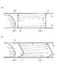
図6(a)は、比較例に係るディフューザ20における設計点の流量時での流れを模式的に示す子午面断面図である。図6(b)は、本実施形態に係るディフューザ5における設計点の流量時での流れを模式的に示す子午面断面図である。図7(a)は、比較例に係るディフューザ20における非設計点の流量時での流れを模式的に示す子午面断面図である。図7(b)は、本実施形態に係るディフューザ5における非設計点の流量時での流れを模式的に示す子午面断面図である。
図6、図7中に示す矢印は、ディフューザ5の翼11,21の負圧面104側を通過する流れの流線を表している。図6は、設計点近傍の場合、図7は設計点より低流量の場合における流れ場の一例を示している。
Next, with reference to FIGS. 6 to 7, a mechanism for suppressing separation and backflow in thediffuser 5 according to this embodiment will be described.
FIG. 6A is a meridional cross-sectional view schematically showing the flow at the design point flow rate in thediffuser 20 according to the comparative example. FIG. 6B is a meridional cross-sectional view schematically showing the flow at the design point flow rate in thediffuser 5 according to the present embodiment. FIG. 7A is a meridional cross-sectional view schematically showing the flow at the non-design point flow rate in thediffuser 20 according to the comparative example. FIG. 7B is a meridional cross-sectional view schematically showing the flow at the flow rate of the non-design point in thediffuser 5 according to the present embodiment.
The arrows shown in FIGS. 6 and 7 indicate streamlines of the flow passing through thesuction surface 104 side of theblades 11 and 21 of thediffuser 5. FIG. 6 shows an example of the flow field in the case of the vicinity of the design point, and FIG. 7 shows an example of the flow field in the case of a flow rate lower than the design point.

基本的に、羽根車1によって昇圧された流れ場は、図6、図7の左側に示すようにハブ面12からシュラウド面13にかけて不均一な流れ分布201を有している。図6、図7中では流れの分布201を二次元的な線として表しているが、実際は、流速が異なるだけではなく、流れ角も異なるため、三次元的に非常に複雑な流れを有していることとなる。特に、本実施形態で対象とするオープン型の羽根車1を有する流体機械100では、羽根車1の羽根1bとケーシング7の内側壁面14との間には翼端漏れ流れが存在する(図1参照)。このため、流れの子午面方向(子午面断面における流路に沿った方向;ディフューザ5では径方向)成分は非常に低く、周方向の成分が支配的であることが多い。流量条件によっては、羽根車1側へと逆流するような条件もあり得る。そのような流れ場が従来の比較例に係るディフューザ20へと流入すると、ハブ面12、シュラウド面13近傍の流れは、ディフューザ20の流路内での断面平均静圧勾配に打ち勝つことができず、図6(a)、図7(a)中に破線で示す逆流D、剥離を生じることとなる。  Basically, the flow field boosted by theimpeller 1 has anon-uniform flow distribution 201 from thehub surface 12 to theshroud surface 13 as shown on the left side of FIGS. 6 and 7, theflow distribution 201 is represented as a two-dimensional line. Actually, however, not only the flow velocity is different, but also the flow angle is different, so that theflow distribution 201 is very complicated in three dimensions. Will be. In particular, in thefluid machine 100 having theopen impeller 1 targeted in the present embodiment, a blade tip leakage flow exists between theblade 1b of theimpeller 1 and theinner wall surface 14 of the casing 7 (FIG. 1). reference). For this reason, the meridional direction direction of the flow (direction along the flow path in the meridional section; radial direction in the diffuser 5) is very low, and the circumferential direction component is often dominant. Depending on the flow rate conditions, there may be conditions such as backflow toward theimpeller 1 side. When such a flow field flows into thediffuser 20 according to the conventional comparative example, the flow in the vicinity of thehub surface 12 and theshroud surface 13 cannot overcome the cross-sectional average static pressure gradient in the flow path of thediffuser 20. 6 (a) and FIG. 7 (a), the reverse flow D indicated by the broken line and peeling occur.

クローズド型の羽根車を有する流体機械の場合、羽根車出口の流れは、シュラウド側で子午面方向流速が速いことが多く、図6に示すような、シュラウド面13付近で急激に子午面方向流速が低下するような流れ分布201とは、基本的に異なっている。その結果、クローズド型の羽根車を有する流体機械では、主にハブ面12側で逆流を生じやすく、シュラウド面13側では逆流現象があまり生じない。そのため、あまりシュラウド面13側の翼11の形状に配慮をしなくてもよかった。  In the case of a fluid machine having a closed type impeller, the flow at the exit of the impeller often has a high meridional direction flow velocity on the shroud side, and the meridional direction flow velocity suddenly near theshroud surface 13 as shown in FIG. This is basically different from theflow distribution 201 in which the flow rate decreases. As a result, in a fluid machine having a closed-type impeller, a backflow is likely to occur mainly on thehub surface 12 side, and a backflow phenomenon does not occur much on theshroud surface 13 side. Therefore, it is not necessary to consider the shape of theblade 11 on theshroud surface 13 side.

一方、本実施形態が対象とするオープン型の羽根車1を有する流体機械100では、シュラウド側の流れ角が小さく、かつ子午面方向の流速も低い。このため、ディフューザ5の複数の翼11から構成される翼列部に流体が流入する時点で、シュラウド面13側は逆流Dが生じることも多い(図6(a)参照)。  On the other hand, in thefluid machine 100 having theopen impeller 1 targeted by this embodiment, the flow angle on the shroud side is small, and the flow velocity in the meridional direction is also low. For this reason, the backflow D often occurs on theshroud surface 13 side at the time when the fluid flows into the blade row portion composed of the plurality ofblades 11 of the diffuser 5 (see FIG. 6A).

そのため、本実施形態では、翼11のダイヘドラル分布は、正方向のダイヘドラル量Δδを有する翼高さ方向の中央位置Mから、シュラウド面13まで単調減少している。つまり、本実施形態では、翼高さ方向の中央位置Mからシュラウド面13にかけて正方向のダイヘドラル量Δδが付与され、かつ、翼面が回転軸2に対して傾斜するように翼11が変形させられている。これにより、図6(b)に示すように、翼11の負圧面104上の流線を強制的にシュラウド面13側に寄せる翼力を流れに与えることができる。この翼力は、図6(a)に示すような逆流Dを押し戻す効果を発揮するため、シュラウド面13における逆流Dを抑えることができる。  Therefore, in the present embodiment, the dihedral distribution of theblade 11 monotonously decreases from the center position M in the blade height direction having the positive dihedral amount Δδ to theshroud surface 13. That is, in the present embodiment, theblade 11 is deformed so that a positive dihedral amount Δδ is given from the center position M in the blade height direction to theshroud surface 13 and the blade surface is inclined with respect to the rotating shaft 2. It has been. As a result, as shown in FIG. 6 (b), it is possible to give the flow a blade force that forcibly brings the streamline on thesuction surface 104 of theblade 11 toward theshroud surface 13. Since this blade force exerts an effect of pushing back the reverse flow D as shown in FIG. 6A, the reverse flow D on theshroud surface 13 can be suppressed.

また、図7に示すように、流体機械100の運転条件が設計点とは異なる条件の場合、一般的に、ハブ面12側の子午面方向の流速が急激に低下する流れ分布201となる傾向にある。このため、オープン型の羽根車1、クローズド型羽根車のどちらであっても、ハブ面12上で逆流Dが生じる(図7(a)参照)。  In addition, as shown in FIG. 7, when the operating conditions of thefluid machine 100 are different from the design points, generally, theflow distribution 201 tends to decrease rapidly in the meridional direction on thehub surface 12 side. It is in. For this reason, the backflow D is generated on thehub surface 12 in either theopen type impeller 1 or the closed type impeller (see FIG. 7A).

そのため、本実施形態では、翼11のダイヘドラル分布は、ハブ面12から翼高さ方向の中央位置Mに向けて増加し、翼高さ方向の中央位置までに一つの極大値Pを示している。つまり、本実施形態では、ハブ面12から翼高さ方向の中央位置Mまでの間に、正方向のダイヘドラル量Δδが付与され、かつ、ダイヘドラル量Δδが減少に転じるように、羽根車1の回転方向と逆方向に凸形状を呈する凸部が設けられている。これにより、図7(b)に示すように、翼11の負圧面104上の流線を強制的にハブ面12側に寄せる翼力を流れに与えることができる。この翼力は、図7(a)に示すような逆流Dを押し戻す効果を発揮するため、ハブ面12における逆流Dを抑えることができる。  Therefore, in this embodiment, the dihedral distribution of theblade 11 increases from thehub surface 12 toward the center position M in the blade height direction, and shows one maximum value P up to the center position in the blade height direction. . In other words, in the present embodiment, the forward dihedral amount Δδ is given between thehub surface 12 and the blade height direction center position M, and the dihedral amount Δδ starts to decrease. A convex portion having a convex shape in the direction opposite to the rotation direction is provided. As a result, as shown in FIG. 7B, a blade force that forcibly moves the streamline on thesuction surface 104 of theblade 11 toward thehub surface 12 can be applied to the flow. Since this blade force exerts an effect of pushing back the reverse flow D as shown in FIG. 7A, the reverse flow D on thehub surface 12 can be suppressed.

ハブ面12側、およびシュラウド面13側の双方に適切に翼力を作用させることが重要である。特に、非設計点での流れ場では、ハブ面12側で比較的大きな逆流が発生する傾向にあるが、一方でシュラウド面13側の逆流は、設計点、非設計点の間で大きな差は現れにくい。したがって、図3に示すように、翼11のダイヘドラル分布において、ハブ面12側に急激な傾斜を示す急傾斜部Aを設け、シュラウド面13側には相対的にゆるい傾斜を示す緩傾斜部Bを設けることによって、翼力を調整することが重要となる。そのため、正方向に増加するダイヘドラル量Δδが減少に転じる凸部をできるだけハブ面12側に設けることが、ハブ面12側とシュラウド面13側との双方で逆流をより抑制する上で重要な要素となる。ここで、傾斜は、ダイヘドラル量Δδの変化量を翼高さ方向の位置の変化量で除した値である。  It is important to apply the blade force appropriately to both thehub surface 12 side and theshroud surface 13 side. In particular, in the flow field at the non-design point, a relatively large backflow tends to occur on thehub surface 12 side. On the other hand, the backflow on theshroud surface 13 side has a large difference between the design point and the non-design point. Hard to appear. Therefore, as shown in FIG. 3, in the dihedral distribution of theblade 11, a steeply inclined portion A showing a steep inclination is provided on thehub surface 12 side, and a gently inclined portion B showing a relatively gentle inclination is provided on theshroud surface 13 side. It is important to adjust the wing force by providing. Therefore, it is an important factor to further suppress backflow on both thehub surface 12 side and theshroud surface 13 side by providing a convex portion on thehub surface 12 side as much as possible so that the dihedral amount Δδ that increases in the forward direction decreases. It becomes. Here, the inclination is a value obtained by dividing the amount of change in the die-hedra amount Δδ by the amount of change in the position in the blade height direction.

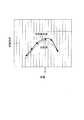
図8は、従来の比較例に係るディフューザ20(図4参照)を搭載した流体機械と、本実施形態に係るディフューザ5(図5参照)を搭載した流体機械100との性能を比較したグラフである。図8に示すグラフは、流体機械の断熱効率の比較を示している。
図8に示すように、本実施形態に係るディフューザ5を備える流体機械100は、従来の比較例に係るディフューザ20を備える流体機械に比べて、設計点Eにおいて1.2%効率が向上していることがわかる。このことから、本実施形態に係るディフューザ5の翼11の形状の優位性が示されていると言える。
FIG. 8 is a graph comparing the performance of a fluid machine equipped with a diffuser 20 (see FIG. 4) according to a conventional comparative example and afluid machine 100 equipped with adiffuser 5 according to the present embodiment (see FIG. 5). is there. The graph shown in FIG. 8 shows a comparison of the thermal insulation efficiency of fluid machines.
As shown in FIG. 8, thefluid machine 100 including thediffuser 5 according to the present embodiment is 1.2% more efficient at the design point E than the fluid machine including thediffuser 20 according to the conventional comparative example. I understand that. From this, it can be said that the superiority of the shape of theblade 11 of thediffuser 5 according to the present embodiment is shown.

図9(a)は、従来の比較例に係るディフューザ20を搭載した流体機械における数値解析(3次元流体解析)によって得られたディフューザ20周囲の流れ場の一例を模式的に示す図である。図9(b)は、本実施形態に係るディフューザ5を搭載した流体機械100における数値解析によって得られたディフューザ5周囲の流れ場の一例を模式的に示す図である。図9(a)および図9(b)に示す2つのディフューザ周囲の流れ場は、同じ流量点で得られたものを示している。
図9(a)に示すように、比較例に係るディフューザ20では、図6〜図7で示したような、ディフューザ20の翼21の負圧面104側のハブ面12、シュラウド面13上に逆流Dを生じる領域(逆流域)が存在していることがわかる。一方、図9(b)に示すように、本実施形態に係るディフューザ5の翼11の負圧面104側では逆流域が消失していることがわかる。
また、図9(a)および図9(b)には、ハブ面12上の限界流線が合わせて表示されている。ディフューザ5の翼11の下流部におけるハブ面12上の限界流線は、比較例では周方向に旋回するような流線を描いているのに対し、本実施形態では、放射状に近付く方向に少し変化した流線を描いていることがわかる。これは、本実施形態では、ハブ面12側の流れ角が増加し、逆流が生じにくい流れ場となっていることを意味する。
このように図8および図9から、本実施形態に係るディフューザ5の翼11の形状の優位性が、性能(断熱効率)と流れ場の双方から確認することができた。
FIG. 9A is a diagram schematically illustrating an example of a flow field around thediffuser 20 obtained by numerical analysis (three-dimensional fluid analysis) in a fluid machine equipped with adiffuser 20 according to a conventional comparative example. FIG. 9B is a diagram schematically illustrating an example of a flow field around thediffuser 5 obtained by numerical analysis in thefluid machine 100 equipped with thediffuser 5 according to the present embodiment. The flow fields around the two diffusers shown in FIGS. 9A and 9B show those obtained at the same flow point.
As shown in FIG. 9A, in thediffuser 20 according to the comparative example, the reverse flow flows on thehub surface 12 and theshroud surface 13 on thesuction surface 104 side of theblade 21 of thediffuser 20 as shown in FIGS. 6 to 7. It can be seen that there is a region (back flow region) where D occurs. On the other hand, as shown in FIG. 9B, it can be seen that the backflow region disappears on thesuction surface 104 side of theblade 11 of thediffuser 5 according to the present embodiment.
Further, in FIGS. 9A and 9B, limit streamlines on thehub surface 12 are displayed together. In the comparative example, the limiting streamline on thehub surface 12 in the downstream portion of thewing 11 of thediffuser 5 depicts a streamline that swirls in the circumferential direction, whereas in the present embodiment, the limit streamline slightly approaches the radial direction. It can be seen that the streamline has changed. This means that in the present embodiment, the flow angle on thehub surface 12 side is increased, and the flow field is less likely to cause backflow.
Thus, from FIG. 8 and FIG. 9, the superiority of the shape of theblade 11 of thediffuser 5 according to the present embodiment could be confirmed from both the performance (adiabatic efficiency) and the flow field.

前記したように、本実施形態では、ディフューザ5の各々の翼11は、基準となる翼型11aが翼高さ方向に、該翼高さ方向と垂直な平面内での移動を伴って積層された形状で形成されている。ここで、翼高さ方向と垂直な平面内における移動方向のうち、翼型11aの前縁101と後縁102とを結ぶ翼弦C方向に垂直な方向の成分であって羽根車1の回転方向と逆の方向に移動させることを正方向のダイヘドラル移動と呼ぶ。そして、翼高さ方向の位置とダイヘドラル量との関係を示す分布をダイヘドラル分布が、ハブ面12からシュラウド面13に向けて、増加し、一つの極大値Pを示した後、減少している。また、ダイヘドラル分布において極大値Pを示す位置は、翼11の翼高さ方向の中央位置Mよりもハブ面12側に設定されている。  As described above, in the present embodiment, eachblade 11 of thediffuser 5 is stacked with thereference airfoil 11a moving in the blade height direction in a plane perpendicular to the blade height direction. It is formed in a different shape. Here, among the moving directions in a plane perpendicular to the blade height direction, the rotation component of theimpeller 1 is a component in a direction perpendicular to the chord C direction connecting theleading edge 101 and the trailingedge 102 of theairfoil 11a. Moving in the opposite direction to the direction is called forward dihedral movement. The distribution indicating the relationship between the position in the blade height direction and the amount of the dihedral is increased after the dihedral distribution increases from thehub surface 12 toward theshroud surface 13 and shows one maximum value P, and then decreases. . Further, the position showing the maximum value P in the dihedral distribution is set closer to thehub surface 12 than the center position M in the blade height direction of theblade 11.

このような本実施形態では、オープン型の羽根車1を有する流体機械100において、ディフューザ5の翼11の負圧面104上の流れに対してハブ面12やシュラウド面13に向かう翼力を作用させることができる。これにより、ハブ面12やシュラウド面13における逆流の発生を抑えることが可能となる。しかも、ダイヘドラル分布において極大値Pを示す位置が翼11の翼高さ方向の中央位置Mよりもハブ面12側に設定されているため、ハブ面12側に形成される急傾斜部Aによってハブ面12に向かう翼力をより大きく作用させることができる。これにより、ハブ面12側で比較的大きな逆流が発生する傾向にある非設計点(低流量時)での流れ場でも、逆流の発生を抑えることが可能となる。
すなわち、本実施形態によれば、オープン型の羽根車1を備える流体機械100において、羽根付きディフューザ5における逆流をより抑制することができる。
そして、羽根付きディフューザ5における逆流を抑制することで、作動範囲を損ねることなく、高効率化を実現可能な流体機械100を提供できる。
In this embodiment, in thefluid machine 100 having theopen impeller 1, the blade force toward thehub surface 12 and theshroud surface 13 is applied to the flow on thesuction surface 104 of theblade 11 of thediffuser 5. be able to. Thereby, it is possible to suppress the occurrence of backflow on thehub surface 12 and theshroud surface 13. Moreover, since the position showing the maximum value P in the dihedral distribution is set on thehub surface 12 side with respect to the center position M in the blade height direction of theblade 11, the hub is formed by the steeply inclined portion A formed on thehub surface 12 side. The wing force toward thesurface 12 can be applied more greatly. This makes it possible to suppress the occurrence of backflow even in a flow field at a non-design point (at a low flow rate) where a relatively large backflow tends to occur on thehub surface 12 side.
That is, according to this embodiment, in thefluid machine 100 including theopen impeller 1, the backflow in thevaned diffuser 5 can be further suppressed.
And thefluid machine 100 which can implement | achieve high-efficiency can be provided, without impairing an operating range by suppressing the backflow in thevaned diffuser 5. FIG.

また、本実施形態では、極大値Pを示す位置は、翼の翼高さ方向においてハブ面12と交差する端縁位置を0%、シュラウド面13と交差する端縁位置を100%とした場合に、25%以上50%未満の位置に設定されている。このように極大値Pを示す位置を所定の範囲内に設定することによって、ハブ面12側で比較的大きな逆流が発生する傾向にある非設計点(低流量時)での流れ場を含め、ハブ面12側およびシュラウド面13側の双方で逆流をより抑制することが可能となる。  Further, in the present embodiment, the position showing the maximum value P is the case where the edge position intersecting thehub surface 12 in the blade height direction of the blade is 0% and the edge position intersecting theshroud surface 13 is 100%. Furthermore, it is set at a position of 25% or more and less than 50%. In this way, by setting the position showing the maximum value P within a predetermined range, including a flow field at a non-design point (at a low flow rate) where a relatively large backflow tends to occur on thehub surface 12 side, Back flow can be further suppressed on both thehub surface 12 side and theshroud surface 13 side.

また、本実施形態では、翼11の翼面の全領域のうち、70%以上の領域が、羽根車1の回転軸2に対して傾斜している。このような構成によれば、翼11において傾斜した翼面が広範囲に形成されているため、翼11の翼面からより大きな翼力を作用させることが可能となる。  In the present embodiment, 70% or more of the entire region of the blade surface of theblade 11 is inclined with respect to the rotating shaft 2 of theimpeller 1. According to such a configuration, since the blade surface inclined in theblade 11 is formed in a wide range, a larger blade force can be applied from the blade surface of theblade 11.

また、本実施形態では、ダイヘドラル分布が、ハブ面12からシュラウド面13に向けて、ハブ面12から極大値Pを示す位置まで単調増加し、極大値Pを示す位置からシュラウド面13まで単調減少している。このような構成によれば、翼11の翼面からより大きな翼力を作用させることができるとともに、翼11の負圧面104上の流れがより滑らかになり、効率が向上する。  In this embodiment, the dihedral distribution monotonously increases from thehub surface 12 toward theshroud surface 13 from thehub surface 12 to the position where the maximum value P is shown, and monotonically decreases from the position where the maximum value P is shown to theshroud surface 13. doing. According to such a configuration, a larger blade force can be applied from the blade surface of theblade 11, and the flow on thesuction surface 104 of theblade 11 becomes smoother and efficiency is improved.

以上、本発明について実施形態に基づいて説明したが、本発明は前記した実施形態に限定されるものではなく、様々な変形例が含まれる。例えば、前記した実施形態は本発明を分かりやすく説明するために詳細に説明したものであり、必ずしも説明した全ての構成を備えるものに限定されるものではない。また、前記した実施形態の構成の一部について、他の構成の追加・削除・置換をすることが可能である。  As mentioned above, although this invention was demonstrated based on embodiment, this invention is not limited to above-described embodiment, Various modifications are included. For example, the above-described embodiment has been described in detail for easy understanding of the present invention, and is not necessarily limited to one having all the configurations described. Further, it is possible to add, delete, and replace other configurations for a part of the configuration of the above-described embodiment.

例えば、前記した実施形態では、流体機械100が遠心送風機や遠心ブロワ、遠心圧縮機である遠心式流体機械について説明したが、本発明はこれに限定されるものではない。本発明は、例えばポンプ等の他の遠心式流体機械にも適用可能である。また、本発明は、斜流式の流体機械にも適用可能である。  For example, in the above-described embodiment, the centrifugal fluid machine in which thefluid machine 100 is a centrifugal blower, a centrifugal blower, or a centrifugal compressor has been described, but the present invention is not limited to this. The present invention is also applicable to other centrifugal fluid machines such as a pump. The present invention is also applicable to a mixed flow type fluid machine.

また、前記した実施形態では、翼11は、ケーシング7に取り付けられたハブ板部8の表面であるハブ面12上に立設されているが、本発明はこれに限定されるものではない。例えば、翼11は、ケーシング7に取り付けられたシュラウド板部の表面であるシュラウド面13上に立設されていてもよい。あるいは、翼11は、ハブ板部8とシュラウド板部との間に設けられていてもよい。  In the above-described embodiment, theblades 11 are erected on thehub surface 12 that is the surface of thehub plate portion 8 attached to thecasing 7, but the present invention is not limited to this. For example, theblade 11 may be erected on ashroud surface 13 that is a surface of a shroud plate portion attached to thecasing 7. Or the wing |blade 11 may be provided between thehub board part 8 and the shroud board part.

また、前記した実施形態では、翼11を規定するために基準となる翼型11aを積層する際の翼型11aの移動方向が、ダイヘドラル移動方向の移動のみ(スイープ量Δσ=0)である場合について説明したが、本発明はこれに限定されるものではない。例えば、本発明は、ダイヘドラル移動方向の移動とスイープ移動方向の移動とが組み合わされた場合にも適用可能であり、この場合でも前記した実施形態と同様の効果を得ることができる。すなわち、本発明で最も重要な点は、翼11を規定するために翼型11aを積層する際のダイヘドラル分布が、図3に例示するような形状を有することである。  Further, in the above-described embodiment, the movement direction of theairfoil 11a when laminating theairfoil 11a serving as a reference for defining theblade 11 is only the movement in the dihedral movement direction (sweep amount Δσ = 0). However, the present invention is not limited to this. For example, the present invention can be applied to the case where the movement in the dihedral movement direction and the movement in the sweep movement direction are combined, and even in this case, the same effect as the above-described embodiment can be obtained. That is, the most important point in the present invention is that the dihedral distribution at the time of stacking theairfoil 11a to define theblade 11 has a shape as illustrated in FIG.

また、図3に示すダイヘドラル分布では、シュラウド面13上でのダイヘドラル量は、ハブ面12上でのダイヘドラル量と同じであるが、これに限定されるものではなく、ハブ面12上でのダイヘドラル量に対して正方向あるいは負方向にずれていてもよい。  In the dihedral distribution shown in FIG. 3, the dihedral amount on theshroud surface 13 is the same as the dihedral amount on thehub surface 12, but is not limited to this, and the dihedral amount on thehub surface 12 is not limited thereto. It may be displaced in the positive direction or the negative direction with respect to the quantity.

1 羽根車
1a ハブ板
1b 羽根
2 回転軸
3 吸込口配管
4 インレットガイドベーン
5 ディフューザ
6 スクロール
7 ケーシング
8 ハブ板部
11 翼
11a 翼型
12 ハブ面
13 シュラウド面
14 内側壁面
15 羽根車前縁
16 羽根車後縁
22 吸入通路
23 排出通路
100 流体機械
101 前縁
102 後縁
103 圧力面(翼面)
104 負圧面(翼面)
201 羽根車出口の流れ分布
A 急傾斜部
B 緩傾斜部
C 翼弦
D 逆流
E 設計点
M 中央位置
P 極大値
Δδ ダイヘドラル量
Δσ スイープ量
DESCRIPTION OFSYMBOLS 1 Impeller1a Hub plate 1b Blade 2Rotating shaft 3Suction port piping 4Inlet guide vane 5Diffuser 6Scroll 7Casing 8Hub plate part 11Wing 11a Airfoil 12Hub surface 13Shroud surface 14Inner wall surface 15 Impeller front edge 16 Blade Carrear edge 22Suction passage 23Discharge passage 100Fluid machine 101Front edge 102Rear edge 103 Pressure surface (blade surface)
104 Suction surface (wing surface)
201 Flow distribution at impeller exit A Steeply inclined part B Slightly inclined part C Blade chord D Backflow E Design point M Center position P Maximum value Δδ Dihedral amount Δσ Sweep amount

Claims (4)

Translated fromJapanese
円管形状をなすハブ板、および前記ハブ板の外周面に配置されている複数の羽根を有するオープン型の羽根車と、
前記羽根車の下流に配置されている羽根付きディフューザと、を備え、
前記羽根付きディフューザは、前記羽根車の下流側においてハブ面とシュラウド面との間に形成された流路中に周方向に間隔をあけて配置された複数の翼を有しており、
各々の前記翼は、基準となる翼型が前記羽根車の回転軸の軸方向である翼高さ方向に、該翼高さ方向と垂直な平面内での移動を伴って積層された形状で形成されており、
前記翼高さ方向と垂直な平面内における移動方向のうち、基準となる翼型の前縁と後縁とを結ぶ翼弦方向に垂直な方向の成分であって羽根車の回転方向と逆の方向に移動させることを正方向の移動とするダイヘドラル分布が、前記ハブ面から前記シュラウド面に向けて、増加し、一つの極大値を示した後、減少しており、
前記極大値を示す位置は、前記翼の翼高さ方向の中央位置よりも前記ハブ面側に設定されていることを特徴とする流体機械。
A hub plate having a circular tube shape, and an open impeller having a plurality of blades disposed on the outer peripheral surface of the hub plate;
A vaned diffuser disposed downstream of the impeller,
The vaned diffuser has a plurality of blades arranged at intervals in the circumferential direction in a flow path formed between the hub surface and the shroud surface on the downstream side of the impeller,
Each of the blades has a shape in which a reference airfoil is stacked in a blade height direction, which is an axial direction of the rotation shaft of the impeller, with movement in a plane perpendicular to the blade height direction. Formed,
Of the moving directions in a plane perpendicular to the blade height direction, the component is in the direction perpendicular to the chord direction connecting the leading edge and the trailing edge of the reference airfoil, and is opposite to the rotational direction of the impeller. The dihedral distribution with the positive movement as the movement in the direction increases from the hub surface toward the shroud surface, and decreases after showing one maximum value,
The fluid machine according to claim 1, wherein the position showing the maximum value is set closer to the hub surface than the center position of the blade in the blade height direction.
前記極大値を示す位置は、前記翼の翼高さ方向において前記ハブ面と交差する端縁位置を0%、前記シュラウド面と交差する端縁位置を100%とした場合に、25%以上50%未満の位置に設定されていることを特徴とする請求項1に記載の流体機械。  The position showing the maximum value is 25% or more and 50% when the edge position intersecting the hub surface in the blade height direction of the blade is 0% and the edge position intersecting the shroud surface is 100%. The fluid machine according to claim 1, wherein the fluid machine is set at a position less than%. 前記翼の翼面の全領域のうち、70%以上の領域が前記回転軸に対して傾斜していることを特徴とする請求項1または請求項2に記載の流体機械。  3. The fluid machine according to claim 1, wherein 70% or more of the entire region of the blade surface of the blade is inclined with respect to the rotation axis. 4. 前記ダイヘドラル分布が、前記ハブ面から前記シュラウド面に向けて、前記ハブ面から前記極大値を示す位置まで単調増加し、前記極大値を示す位置から前記シュラウド面まで単調減少していることを特徴とする請求項1または請求項2に記載の流体機械。  The dihedral distribution monotonously increases from the hub surface to the position showing the maximum value, and monotonically decreases from the position showing the maximum value to the shroud surface from the hub surface toward the shroud surface. The fluid machine according to claim 1 or 2.
JP2016224051A2016-11-172016-11-17 Fluid machineActiveJP6785623B2 (en)

Priority Applications (1)

Application NumberPriority DateFiling DateTitle
JP2016224051AJP6785623B2 (en)2016-11-172016-11-17 Fluid machine

Applications Claiming Priority (1)

Application NumberPriority DateFiling DateTitle
JP2016224051AJP6785623B2 (en)2016-11-172016-11-17 Fluid machine

Publications (2)

Publication NumberPublication Date
JP2018080653Atrue JP2018080653A (en)2018-05-24
JP6785623B2 JP6785623B2 (en)2020-11-18

Family

ID=62198773

Family Applications (1)

Application NumberTitlePriority DateFiling Date
JP2016224051AActiveJP6785623B2 (en)2016-11-172016-11-17 Fluid machine

Country Status (1)

CountryLink
JP (1)JP6785623B2 (en)

Cited By (3)

* Cited by examiner, † Cited by third party
Publication numberPriority datePublication dateAssigneeTitle
JP2021085347A (en)*2019-11-272021-06-03日立グローバルライフソリューションズ株式会社Air blower and washing machine
US11261878B2 (en)2019-08-222022-03-01Mitsubishi Heavy Industries, Ltd.Vaned diffuser and centrifugal compressor
JP2022056648A (en)*2020-09-302022-04-11日立グローバルライフソリューションズ株式会社 Blower and washing machine equipped with it

Cited By (7)

* Cited by examiner, † Cited by third party
Publication numberPriority datePublication dateAssigneeTitle
US11261878B2 (en)2019-08-222022-03-01Mitsubishi Heavy Industries, Ltd.Vaned diffuser and centrifugal compressor
JP2021085347A (en)*2019-11-272021-06-03日立グローバルライフソリューションズ株式会社Air blower and washing machine
WO2021106317A1 (en)*2019-11-272021-06-03日立グローバルライフソリューションズ株式会社Blower and washing machine
CN114729648A (en)*2019-11-272022-07-08日立环球生活方案株式会社Blower and washing machine
JP7452989B2 (en)2019-11-272024-03-19日立グローバルライフソリューションズ株式会社 Blower and washing machine
JP2022056648A (en)*2020-09-302022-04-11日立グローバルライフソリューションズ株式会社 Blower and washing machine equipped with it
JP7516193B2 (en)2020-09-302024-07-16日立グローバルライフソリューションズ株式会社 Blower and washing machine equipped with same

Also Published As

Publication numberPublication date
JP6785623B2 (en)2020-11-18

Similar Documents

PublicationPublication DateTitle
JP5316365B2 (en) Turbo fluid machine
JP5879103B2 (en) Centrifugal fluid machine
JP5233436B2 (en) Centrifugal compressor with vaneless diffuser and vaneless diffuser
JP5333170B2 (en) Centrifugal compressor and design method thereof
JP5608062B2 (en) Centrifugal turbomachine
JP5766595B2 (en) Centrifugal turbomachine
CN109790853B (en) Centrifugal compressors and turbochargers
JP4888436B2 (en) Centrifugal compressor, its impeller and its operating method
WO2014087690A1 (en)Centrifugal compressor
JP2014109193A (en)Centrifugal fluid machine
JP2018091207A (en) Centrifugal compressor and turbocharger
JP6362980B2 (en) Turbo machine
JP6785623B2 (en) Fluid machine
JP2006002689A (en) Blower
JP6064003B2 (en) Centrifugal fluid machine
JP6854687B2 (en) Multi-stage fluid machine
JP2016050486A (en)Fluid machinery and impeller of fluid machinery
JP2020097940A (en) Improved scroll for turbomachine, turbomachine with said scroll, and method of operation
JP6758924B2 (en) Impeller
JP5483096B2 (en) Turbine 3D impeller
JP2012036783A (en)Radial turbine impeller
JP2019007383A (en)Centrifugal fluid machine
WO2017170285A1 (en)Centrifugal impeller, and centrifugal fluid machine provided with same

Legal Events

DateCodeTitleDescription
A621Written request for application examination

Free format text:JAPANESE INTERMEDIATE CODE: A621

Effective date:20190723

A711Notification of change in applicant

Free format text:JAPANESE INTERMEDIATE CODE: A712

Effective date:20200204

A977Report on retrieval

Free format text:JAPANESE INTERMEDIATE CODE: A971007

Effective date:20200421

A131Notification of reasons for refusal

Free format text:JAPANESE INTERMEDIATE CODE: A131

Effective date:20200526

A521Written amendment

Free format text:JAPANESE INTERMEDIATE CODE: A523

Effective date:20200715

TRDDDecision of grant or rejection written
A01Written decision to grant a patent or to grant a registration (utility model)

Free format text:JAPANESE INTERMEDIATE CODE: A01

Effective date:20201006

A61First payment of annual fees (during grant procedure)

Free format text:JAPANESE INTERMEDIATE CODE: A61

Effective date:20201027

R150Certificate of patent or registration of utility model

Ref document number:6785623

Country of ref document:JP

Free format text:JAPANESE INTERMEDIATE CODE: R150


[8]ページ先頭

©2009-2025 Movatter.jp