JP2018064943A - Expansion ring for braided stent - Google Patents
Expansion ring for braided stentDownload PDFInfo
- Publication number
- JP2018064943A JP2018064943AJP2017204234AJP2017204234AJP2018064943AJP 2018064943 AJP2018064943 AJP 2018064943AJP 2017204234 AJP2017204234 AJP 2017204234AJP 2017204234 AJP2017204234 AJP 2017204234AJP 2018064943 AJP2018064943 AJP 2018064943A
- Authority
- JP
- Japan
- Prior art keywords
- intersection
- stent body
- expansion ring
- braided
- stent
- Prior art date
- Legal status (The legal status is an assumption and is not a legal conclusion. Google has not performed a legal analysis and makes no representation as to the accuracy of the status listed.)
- Granted
Links
- 210000000078clawAnatomy0.000claimsabstractdescription39
- 230000000712assemblyEffects0.000claimsabstractdescription24
- 238000000429assemblyMethods0.000claimsabstractdescription24
- 230000007246mechanismEffects0.000claimsdescription43
- 230000006835compressionEffects0.000claimsdescription16
- 238000007906compressionMethods0.000claimsdescription16
- 238000003466weldingMethods0.000claimsdescription8
- 238000002788crimpingMethods0.000claimsdescription7
- 239000000853adhesiveSubstances0.000claimsdescription6
- 230000001070adhesive effectEffects0.000claimsdescription6
- 238000005304joiningMethods0.000claimsdescription6
- 229910052751metalInorganic materials0.000claimsdescription6
- 239000002184metalSubstances0.000claimsdescription6
- 238000005476solderingMethods0.000claimsdescription6
- 238000000034methodMethods0.000description21
- 239000000463materialSubstances0.000description8
- 210000005166vasculatureAnatomy0.000description8
- 241001465754MetazoaSpecies0.000description7
- 238000005516engineering processMethods0.000description6
- 208000017376neurovascular diseaseDiseases0.000description4
- 210000004204blood vesselAnatomy0.000description3
- 150000001875compoundsChemical class0.000description3
- 208000014674injuryDiseases0.000description3
- 239000002245particleSubstances0.000description3
- PXHVJJICTQNCMI-UHFFFAOYSA-NNickelChemical compound[Ni]PXHVJJICTQNCMI-UHFFFAOYSA-N0.000description2
- 238000004026adhesive bondingMethods0.000description2
- 238000002399angioplastyMethods0.000description2
- 230000001419dependent effectEffects0.000description2
- 239000000835fiberSubstances0.000description2
- 230000006870functionEffects0.000description2
- 238000012986modificationMethods0.000description2
- 230000004048modificationEffects0.000description2
- 229910001000nickel titaniumInorganic materials0.000description2
- BASFCYQUMIYNBI-UHFFFAOYSA-NplatinumChemical compound[Pt]BASFCYQUMIYNBI-UHFFFAOYSA-N0.000description2
- 230000002787reinforcementEffects0.000description2
- 230000008733traumaEffects0.000description2
- 230000002792vascularEffects0.000description2
- 206010051113Arterial restenosisDiseases0.000description1
- 241000282693CercopithecidaeSpecies0.000description1
- VYZAMTAEIAYCRO-UHFFFAOYSA-NChromiumChemical compound[Cr]VYZAMTAEIAYCRO-UHFFFAOYSA-N0.000description1
- 241000282412HomoSpecies0.000description1
- 241000124008MammaliaSpecies0.000description1
- 229910001182Mo alloyInorganic materials0.000description1
- 208000031481Pathologic ConstrictionDiseases0.000description1
- 229910000639Spring steelInorganic materials0.000description1
- 206010053648Vascular occlusionDiseases0.000description1
- 208000027418Wounds and injuryDiseases0.000description1
- 230000004913activationEffects0.000description1
- 230000001154acute effectEffects0.000description1
- 230000002411adverseEffects0.000description1
- 238000004873anchoringMethods0.000description1
- 238000010171animal modelMethods0.000description1
- 210000001367arteryAnatomy0.000description1
- 238000005452bendingMethods0.000description1
- 238000009954braidingMethods0.000description1
- 210000004556brainAnatomy0.000description1
- 230000000747cardiac effectEffects0.000description1
- 229910052804chromiumInorganic materials0.000description1
- 239000011651chromiumSubstances0.000description1
- 229910017052cobaltInorganic materials0.000description1
- 239000010941cobaltSubstances0.000description1
- GUTLYIVDDKVIGB-UHFFFAOYSA-Ncobalt atomChemical compound[Co]GUTLYIVDDKVIGB-UHFFFAOYSA-N0.000description1
- 238000010276constructionMethods0.000description1
- 230000006378damageEffects0.000description1
- 230000007547defectEffects0.000description1
- 238000002716delivery methodMethods0.000description1
- 230000000694effectsEffects0.000description1
- 244000144972livestockSpecies0.000description1
- 239000000203mixtureSubstances0.000description1
- 229910052759nickelInorganic materials0.000description1
- HLXZNVUGXRDIFK-UHFFFAOYSA-Nnickel titaniumChemical compound[Ti].[Ti].[Ti].[Ti].[Ti].[Ti].[Ti].[Ti].[Ti].[Ti].[Ti].[Ni].[Ni].[Ni].[Ni].[Ni].[Ni].[Ni].[Ni].[Ni].[Ni].[Ni].[Ni].[Ni].[Ni]HLXZNVUGXRDIFK-UHFFFAOYSA-N0.000description1
- 230000035515penetrationEffects0.000description1
- 229910052697platinumInorganic materials0.000description1
- 238000011084recoveryMethods0.000description1
- 230000003014reinforcing effectEffects0.000description1
- 230000008439repair processEffects0.000description1
- 239000012781shape memory materialSubstances0.000description1
- 229910000679solderInorganic materials0.000description1
- 239000010935stainless steelSubstances0.000description1
- 229910001220stainless steelInorganic materials0.000description1
- 208000037804stenosisDiseases0.000description1
- 230000036262stenosisEffects0.000description1
- 239000000126substanceSubstances0.000description1
- 238000001356surgical procedureMethods0.000description1
- 229910052715tantalumInorganic materials0.000description1
- GUVRBAGPIYLISA-UHFFFAOYSA-Ntantalum atomChemical compound[Ta]GUVRBAGPIYLISA-UHFFFAOYSA-N0.000description1
- 208000021331vascular occlusion diseaseDiseases0.000description1
- 239000011800void materialSubstances0.000description1
Images


Classifications
- A—HUMAN NECESSITIES
- A61—MEDICAL OR VETERINARY SCIENCE; HYGIENE
- A61F—FILTERS IMPLANTABLE INTO BLOOD VESSELS; PROSTHESES; DEVICES PROVIDING PATENCY TO, OR PREVENTING COLLAPSING OF, TUBULAR STRUCTURES OF THE BODY, e.g. STENTS; ORTHOPAEDIC, NURSING OR CONTRACEPTIVE DEVICES; FOMENTATION; TREATMENT OR PROTECTION OF EYES OR EARS; BANDAGES, DRESSINGS OR ABSORBENT PADS; FIRST-AID KITS
- A61F2/00—Filters implantable into blood vessels; Prostheses, i.e. artificial substitutes or replacements for parts of the body; Appliances for connecting them with the body; Devices providing patency to, or preventing collapsing of, tubular structures of the body, e.g. stents
- A61F2/82—Devices providing patency to, or preventing collapsing of, tubular structures of the body, e.g. stents
- A61F2/86—Stents in a form characterised by the wire-like elements; Stents in the form characterised by a net-like or mesh-like structure
- A61F2/90—Stents in a form characterised by the wire-like elements; Stents in the form characterised by a net-like or mesh-like structure characterised by a net-like or mesh-like structure
- A61F2/91—Stents in a form characterised by the wire-like elements; Stents in the form characterised by a net-like or mesh-like structure characterised by a net-like or mesh-like structure made from perforated sheets or tubes, e.g. perforated by laser cuts or etched holes
- A—HUMAN NECESSITIES
- A61—MEDICAL OR VETERINARY SCIENCE; HYGIENE
- A61F—FILTERS IMPLANTABLE INTO BLOOD VESSELS; PROSTHESES; DEVICES PROVIDING PATENCY TO, OR PREVENTING COLLAPSING OF, TUBULAR STRUCTURES OF THE BODY, e.g. STENTS; ORTHOPAEDIC, NURSING OR CONTRACEPTIVE DEVICES; FOMENTATION; TREATMENT OR PROTECTION OF EYES OR EARS; BANDAGES, DRESSINGS OR ABSORBENT PADS; FIRST-AID KITS
- A61F2/00—Filters implantable into blood vessels; Prostheses, i.e. artificial substitutes or replacements for parts of the body; Appliances for connecting them with the body; Devices providing patency to, or preventing collapsing of, tubular structures of the body, e.g. stents
- A61F2/82—Devices providing patency to, or preventing collapsing of, tubular structures of the body, e.g. stents
- A61F2/86—Stents in a form characterised by the wire-like elements; Stents in the form characterised by a net-like or mesh-like structure
- A61F2/89—Stents in a form characterised by the wire-like elements; Stents in the form characterised by a net-like or mesh-like structure the wire-like elements comprising two or more adjacent rings flexibly connected by separate members
- A—HUMAN NECESSITIES
- A61—MEDICAL OR VETERINARY SCIENCE; HYGIENE
- A61F—FILTERS IMPLANTABLE INTO BLOOD VESSELS; PROSTHESES; DEVICES PROVIDING PATENCY TO, OR PREVENTING COLLAPSING OF, TUBULAR STRUCTURES OF THE BODY, e.g. STENTS; ORTHOPAEDIC, NURSING OR CONTRACEPTIVE DEVICES; FOMENTATION; TREATMENT OR PROTECTION OF EYES OR EARS; BANDAGES, DRESSINGS OR ABSORBENT PADS; FIRST-AID KITS
- A61F2/00—Filters implantable into blood vessels; Prostheses, i.e. artificial substitutes or replacements for parts of the body; Appliances for connecting them with the body; Devices providing patency to, or preventing collapsing of, tubular structures of the body, e.g. stents
- A61F2/82—Devices providing patency to, or preventing collapsing of, tubular structures of the body, e.g. stents
- A61F2/844—Devices providing patency to, or preventing collapsing of, tubular structures of the body, e.g. stents folded prior to deployment
- A—HUMAN NECESSITIES
- A61—MEDICAL OR VETERINARY SCIENCE; HYGIENE
- A61F—FILTERS IMPLANTABLE INTO BLOOD VESSELS; PROSTHESES; DEVICES PROVIDING PATENCY TO, OR PREVENTING COLLAPSING OF, TUBULAR STRUCTURES OF THE BODY, e.g. STENTS; ORTHOPAEDIC, NURSING OR CONTRACEPTIVE DEVICES; FOMENTATION; TREATMENT OR PROTECTION OF EYES OR EARS; BANDAGES, DRESSINGS OR ABSORBENT PADS; FIRST-AID KITS
- A61F2/00—Filters implantable into blood vessels; Prostheses, i.e. artificial substitutes or replacements for parts of the body; Appliances for connecting them with the body; Devices providing patency to, or preventing collapsing of, tubular structures of the body, e.g. stents
- A61F2/82—Devices providing patency to, or preventing collapsing of, tubular structures of the body, e.g. stents
- A61F2/848—Devices providing patency to, or preventing collapsing of, tubular structures of the body, e.g. stents having means for fixation to the vessel wall, e.g. barbs
- A—HUMAN NECESSITIES
- A61—MEDICAL OR VETERINARY SCIENCE; HYGIENE
- A61F—FILTERS IMPLANTABLE INTO BLOOD VESSELS; PROSTHESES; DEVICES PROVIDING PATENCY TO, OR PREVENTING COLLAPSING OF, TUBULAR STRUCTURES OF THE BODY, e.g. STENTS; ORTHOPAEDIC, NURSING OR CONTRACEPTIVE DEVICES; FOMENTATION; TREATMENT OR PROTECTION OF EYES OR EARS; BANDAGES, DRESSINGS OR ABSORBENT PADS; FIRST-AID KITS
- A61F2/00—Filters implantable into blood vessels; Prostheses, i.e. artificial substitutes or replacements for parts of the body; Appliances for connecting them with the body; Devices providing patency to, or preventing collapsing of, tubular structures of the body, e.g. stents
- A61F2/82—Devices providing patency to, or preventing collapsing of, tubular structures of the body, e.g. stents
- A61F2/852—Two or more distinct overlapping stents
- A—HUMAN NECESSITIES
- A61—MEDICAL OR VETERINARY SCIENCE; HYGIENE
- A61F—FILTERS IMPLANTABLE INTO BLOOD VESSELS; PROSTHESES; DEVICES PROVIDING PATENCY TO, OR PREVENTING COLLAPSING OF, TUBULAR STRUCTURES OF THE BODY, e.g. STENTS; ORTHOPAEDIC, NURSING OR CONTRACEPTIVE DEVICES; FOMENTATION; TREATMENT OR PROTECTION OF EYES OR EARS; BANDAGES, DRESSINGS OR ABSORBENT PADS; FIRST-AID KITS
- A61F2/00—Filters implantable into blood vessels; Prostheses, i.e. artificial substitutes or replacements for parts of the body; Appliances for connecting them with the body; Devices providing patency to, or preventing collapsing of, tubular structures of the body, e.g. stents
- A61F2/82—Devices providing patency to, or preventing collapsing of, tubular structures of the body, e.g. stents
- A61F2/86—Stents in a form characterised by the wire-like elements; Stents in the form characterised by a net-like or mesh-like structure
- A61F2/90—Stents in a form characterised by the wire-like elements; Stents in the form characterised by a net-like or mesh-like structure characterised by a net-like or mesh-like structure
- A—HUMAN NECESSITIES
- A61—MEDICAL OR VETERINARY SCIENCE; HYGIENE
- A61F—FILTERS IMPLANTABLE INTO BLOOD VESSELS; PROSTHESES; DEVICES PROVIDING PATENCY TO, OR PREVENTING COLLAPSING OF, TUBULAR STRUCTURES OF THE BODY, e.g. STENTS; ORTHOPAEDIC, NURSING OR CONTRACEPTIVE DEVICES; FOMENTATION; TREATMENT OR PROTECTION OF EYES OR EARS; BANDAGES, DRESSINGS OR ABSORBENT PADS; FIRST-AID KITS
- A61F2/00—Filters implantable into blood vessels; Prostheses, i.e. artificial substitutes or replacements for parts of the body; Appliances for connecting them with the body; Devices providing patency to, or preventing collapsing of, tubular structures of the body, e.g. stents
- A61F2/82—Devices providing patency to, or preventing collapsing of, tubular structures of the body, e.g. stents
- A61F2/86—Stents in a form characterised by the wire-like elements; Stents in the form characterised by a net-like or mesh-like structure
- A—HUMAN NECESSITIES
- A61—MEDICAL OR VETERINARY SCIENCE; HYGIENE
- A61F—FILTERS IMPLANTABLE INTO BLOOD VESSELS; PROSTHESES; DEVICES PROVIDING PATENCY TO, OR PREVENTING COLLAPSING OF, TUBULAR STRUCTURES OF THE BODY, e.g. STENTS; ORTHOPAEDIC, NURSING OR CONTRACEPTIVE DEVICES; FOMENTATION; TREATMENT OR PROTECTION OF EYES OR EARS; BANDAGES, DRESSINGS OR ABSORBENT PADS; FIRST-AID KITS
- A61F2/00—Filters implantable into blood vessels; Prostheses, i.e. artificial substitutes or replacements for parts of the body; Appliances for connecting them with the body; Devices providing patency to, or preventing collapsing of, tubular structures of the body, e.g. stents
- A61F2/82—Devices providing patency to, or preventing collapsing of, tubular structures of the body, e.g. stents
- A61F2/92—Stents in the form of a rolled-up sheet expanding after insertion into the vessel, e.g. with a spiral shape in cross-section
- A61F2/93—Stents in the form of a rolled-up sheet expanding after insertion into the vessel, e.g. with a spiral shape in cross-section circumferentially expandable by using ratcheting locks
- A—HUMAN NECESSITIES
- A61—MEDICAL OR VETERINARY SCIENCE; HYGIENE
- A61F—FILTERS IMPLANTABLE INTO BLOOD VESSELS; PROSTHESES; DEVICES PROVIDING PATENCY TO, OR PREVENTING COLLAPSING OF, TUBULAR STRUCTURES OF THE BODY, e.g. STENTS; ORTHOPAEDIC, NURSING OR CONTRACEPTIVE DEVICES; FOMENTATION; TREATMENT OR PROTECTION OF EYES OR EARS; BANDAGES, DRESSINGS OR ABSORBENT PADS; FIRST-AID KITS
- A61F2/00—Filters implantable into blood vessels; Prostheses, i.e. artificial substitutes or replacements for parts of the body; Appliances for connecting them with the body; Devices providing patency to, or preventing collapsing of, tubular structures of the body, e.g. stents
- A61F2/82—Devices providing patency to, or preventing collapsing of, tubular structures of the body, e.g. stents
- A61F2/848—Devices providing patency to, or preventing collapsing of, tubular structures of the body, e.g. stents having means for fixation to the vessel wall, e.g. barbs
- A61F2002/8486—Devices providing patency to, or preventing collapsing of, tubular structures of the body, e.g. stents having means for fixation to the vessel wall, e.g. barbs provided on at least one of the ends
- A—HUMAN NECESSITIES
- A61—MEDICAL OR VETERINARY SCIENCE; HYGIENE
- A61F—FILTERS IMPLANTABLE INTO BLOOD VESSELS; PROSTHESES; DEVICES PROVIDING PATENCY TO, OR PREVENTING COLLAPSING OF, TUBULAR STRUCTURES OF THE BODY, e.g. STENTS; ORTHOPAEDIC, NURSING OR CONTRACEPTIVE DEVICES; FOMENTATION; TREATMENT OR PROTECTION OF EYES OR EARS; BANDAGES, DRESSINGS OR ABSORBENT PADS; FIRST-AID KITS
- A61F2/00—Filters implantable into blood vessels; Prostheses, i.e. artificial substitutes or replacements for parts of the body; Appliances for connecting them with the body; Devices providing patency to, or preventing collapsing of, tubular structures of the body, e.g. stents
- A61F2/82—Devices providing patency to, or preventing collapsing of, tubular structures of the body, e.g. stents
- A61F2/86—Stents in a form characterised by the wire-like elements; Stents in the form characterised by a net-like or mesh-like structure
- A61F2/90—Stents in a form characterised by the wire-like elements; Stents in the form characterised by a net-like or mesh-like structure characterised by a net-like or mesh-like structure
- A61F2/91—Stents in a form characterised by the wire-like elements; Stents in the form characterised by a net-like or mesh-like structure characterised by a net-like or mesh-like structure made from perforated sheets or tubes, e.g. perforated by laser cuts or etched holes
- A61F2/915—Stents in a form characterised by the wire-like elements; Stents in the form characterised by a net-like or mesh-like structure characterised by a net-like or mesh-like structure made from perforated sheets or tubes, e.g. perforated by laser cuts or etched holes with bands having a meander structure, adjacent bands being connected to each other
- A61F2002/9155—Adjacent bands being connected to each other
- A61F2002/91591—Locking connectors, e.g. using male-female connections
- A—HUMAN NECESSITIES
- A61—MEDICAL OR VETERINARY SCIENCE; HYGIENE
- A61F—FILTERS IMPLANTABLE INTO BLOOD VESSELS; PROSTHESES; DEVICES PROVIDING PATENCY TO, OR PREVENTING COLLAPSING OF, TUBULAR STRUCTURES OF THE BODY, e.g. STENTS; ORTHOPAEDIC, NURSING OR CONTRACEPTIVE DEVICES; FOMENTATION; TREATMENT OR PROTECTION OF EYES OR EARS; BANDAGES, DRESSINGS OR ABSORBENT PADS; FIRST-AID KITS
- A61F2210/00—Particular material properties of prostheses classified in groups A61F2/00 - A61F2/26 or A61F2/82 or A61F9/00 or A61F11/00 or subgroups thereof
- A61F2210/0014—Particular material properties of prostheses classified in groups A61F2/00 - A61F2/26 or A61F2/82 or A61F9/00 or A61F11/00 or subgroups thereof using shape memory or superelastic materials, e.g. nitinol
- A—HUMAN NECESSITIES
- A61—MEDICAL OR VETERINARY SCIENCE; HYGIENE
- A61F—FILTERS IMPLANTABLE INTO BLOOD VESSELS; PROSTHESES; DEVICES PROVIDING PATENCY TO, OR PREVENTING COLLAPSING OF, TUBULAR STRUCTURES OF THE BODY, e.g. STENTS; ORTHOPAEDIC, NURSING OR CONTRACEPTIVE DEVICES; FOMENTATION; TREATMENT OR PROTECTION OF EYES OR EARS; BANDAGES, DRESSINGS OR ABSORBENT PADS; FIRST-AID KITS
- A61F2210/00—Particular material properties of prostheses classified in groups A61F2/00 - A61F2/26 or A61F2/82 or A61F9/00 or A61F11/00 or subgroups thereof
- A61F2210/0061—Particular material properties of prostheses classified in groups A61F2/00 - A61F2/26 or A61F2/82 or A61F9/00 or A61F11/00 or subgroups thereof swellable
- A—HUMAN NECESSITIES
- A61—MEDICAL OR VETERINARY SCIENCE; HYGIENE
- A61F—FILTERS IMPLANTABLE INTO BLOOD VESSELS; PROSTHESES; DEVICES PROVIDING PATENCY TO, OR PREVENTING COLLAPSING OF, TUBULAR STRUCTURES OF THE BODY, e.g. STENTS; ORTHOPAEDIC, NURSING OR CONTRACEPTIVE DEVICES; FOMENTATION; TREATMENT OR PROTECTION OF EYES OR EARS; BANDAGES, DRESSINGS OR ABSORBENT PADS; FIRST-AID KITS
- A61F2220/00—Fixations or connections for prostheses classified in groups A61F2/00 - A61F2/26 or A61F2/82 or A61F9/00 or A61F11/00 or subgroups thereof
- A61F2220/0025—Connections or couplings between prosthetic parts, e.g. between modular parts; Connecting elements
- A61F2220/0033—Connections or couplings between prosthetic parts, e.g. between modular parts; Connecting elements made by longitudinally pushing a protrusion into a complementary-shaped recess, e.g. held by friction fit
- A—HUMAN NECESSITIES
- A61—MEDICAL OR VETERINARY SCIENCE; HYGIENE
- A61F—FILTERS IMPLANTABLE INTO BLOOD VESSELS; PROSTHESES; DEVICES PROVIDING PATENCY TO, OR PREVENTING COLLAPSING OF, TUBULAR STRUCTURES OF THE BODY, e.g. STENTS; ORTHOPAEDIC, NURSING OR CONTRACEPTIVE DEVICES; FOMENTATION; TREATMENT OR PROTECTION OF EYES OR EARS; BANDAGES, DRESSINGS OR ABSORBENT PADS; FIRST-AID KITS
- A61F2220/00—Fixations or connections for prostheses classified in groups A61F2/00 - A61F2/26 or A61F2/82 or A61F9/00 or A61F11/00 or subgroups thereof
- A61F2220/0025—Connections or couplings between prosthetic parts, e.g. between modular parts; Connecting elements
- A61F2220/0041—Connections or couplings between prosthetic parts, e.g. between modular parts; Connecting elements using additional screws, bolts, dowels or rivets, e.g. connecting screws
- A—HUMAN NECESSITIES
- A61—MEDICAL OR VETERINARY SCIENCE; HYGIENE
- A61F—FILTERS IMPLANTABLE INTO BLOOD VESSELS; PROSTHESES; DEVICES PROVIDING PATENCY TO, OR PREVENTING COLLAPSING OF, TUBULAR STRUCTURES OF THE BODY, e.g. STENTS; ORTHOPAEDIC, NURSING OR CONTRACEPTIVE DEVICES; FOMENTATION; TREATMENT OR PROTECTION OF EYES OR EARS; BANDAGES, DRESSINGS OR ABSORBENT PADS; FIRST-AID KITS
- A61F2220/00—Fixations or connections for prostheses classified in groups A61F2/00 - A61F2/26 or A61F2/82 or A61F9/00 or A61F11/00 or subgroups thereof
- A61F2220/0025—Connections or couplings between prosthetic parts, e.g. between modular parts; Connecting elements
- A61F2220/0091—Connections or couplings between prosthetic parts, e.g. between modular parts; Connecting elements connected by a hinged linkage mechanism, e.g. of the single-bar or multi-bar linkage type
- A—HUMAN NECESSITIES
- A61—MEDICAL OR VETERINARY SCIENCE; HYGIENE
- A61F—FILTERS IMPLANTABLE INTO BLOOD VESSELS; PROSTHESES; DEVICES PROVIDING PATENCY TO, OR PREVENTING COLLAPSING OF, TUBULAR STRUCTURES OF THE BODY, e.g. STENTS; ORTHOPAEDIC, NURSING OR CONTRACEPTIVE DEVICES; FOMENTATION; TREATMENT OR PROTECTION OF EYES OR EARS; BANDAGES, DRESSINGS OR ABSORBENT PADS; FIRST-AID KITS
- A61F2240/00—Manufacturing or designing of prostheses classified in groups A61F2/00 - A61F2/26 or A61F2/82 or A61F9/00 or A61F11/00 or subgroups thereof
- A61F2240/001—Designing or manufacturing processes
- A—HUMAN NECESSITIES
- A61—MEDICAL OR VETERINARY SCIENCE; HYGIENE
- A61F—FILTERS IMPLANTABLE INTO BLOOD VESSELS; PROSTHESES; DEVICES PROVIDING PATENCY TO, OR PREVENTING COLLAPSING OF, TUBULAR STRUCTURES OF THE BODY, e.g. STENTS; ORTHOPAEDIC, NURSING OR CONTRACEPTIVE DEVICES; FOMENTATION; TREATMENT OR PROTECTION OF EYES OR EARS; BANDAGES, DRESSINGS OR ABSORBENT PADS; FIRST-AID KITS
- A61F2250/00—Special features of prostheses classified in groups A61F2/00 - A61F2/26 or A61F2/82 or A61F9/00 or A61F11/00 or subgroups thereof
- A61F2250/0004—Special features of prostheses classified in groups A61F2/00 - A61F2/26 or A61F2/82 or A61F9/00 or A61F11/00 or subgroups thereof adjustable
- A61F2250/001—Special features of prostheses classified in groups A61F2/00 - A61F2/26 or A61F2/82 or A61F9/00 or A61F11/00 or subgroups thereof adjustable for adjusting a diameter
Landscapes
- Health & Medical Sciences (AREA)
- Engineering & Computer Science (AREA)
- Biomedical Technology (AREA)
- Heart & Thoracic Surgery (AREA)
- Life Sciences & Earth Sciences (AREA)
- Cardiology (AREA)
- Oral & Maxillofacial Surgery (AREA)
- Transplantation (AREA)
- Veterinary Medicine (AREA)
- Vascular Medicine (AREA)
- Public Health (AREA)
- Animal Behavior & Ethology (AREA)
- General Health & Medical Sciences (AREA)
- Optics & Photonics (AREA)
- Physics & Mathematics (AREA)
- Media Introduction/Drainage Providing Device (AREA)
- Prostheses (AREA)
- Surgical Instruments (AREA)
- Adornments (AREA)
Abstract
Description
Translated fromJapanese本開示は、概して、患者の脈管構造における特定欠陥の治療に関し、より詳細には、患者の脈管構造における治療部位への自己拡張型編組ステントに関する。 The present disclosure relates generally to the treatment of specific defects in a patient's vasculature, and more particularly to a self-expanding braided stent to a treatment site in a patient's vasculature.
ステントは、血管に挿入され得、血管内に開いた経路を提供するチューブ状補強材として理解される。ステントは、閉塞した心臓動脈の血管内の血管形成治療において広く使用されており、ステントは、動脈の再狭窄を防ぐために血管形成術手順の後に挿入され得る。ステントは、送達デバイスを使用することによって展開されることが多く、この送達デバイスは、動脈壁を補強する目的でステントを開かせ、動脈内に障害物のない貫通経路を提供することにより、再狭窄を防ぐ。 A stent is understood as a tubular reinforcement that can be inserted into a blood vessel and provides an open path within the blood vessel. Stents are widely used in angioplasty treatment within occluded cardiac arterial vessels, and stents can be inserted after angioplasty procedures to prevent arterial restenosis. Stents are often deployed by using a delivery device that reopens the stent for the purpose of reinforcing the arterial wall and provides an unobstructed penetration path in the artery. Prevent stenosis.
しかしながら、神経脈管構造の脆弱性及び非直線性質は、手順における、例えば、神経脈管障害の修復におけるかかるステントの適用性を制限する。その上、既知の送達方法は、血管閉塞症手術において、特に、ごく小さな脈管、例えば、脳内に発見される脈管などが治療されるべきであるときに、有用性が低い。したがって、選択的な補強材を神経脈管障害の近傍に提供する神経脈管障害の血管閉塞症治療における送達技法と共に使用され得るステントの必要性が存在する。また、血管の外傷又はその破裂の危険性を低減するステントに対する必要性も存在する。以下に述べる様々な実施形態は、これら及びその他の考慮事項に関連して提示されるものである。 However, the fragility and non-linear nature of the neurovasculature limits the applicability of such stents in procedures, for example in the repair of neurovascular disorders. Moreover, known delivery methods are less useful in vaso-occlusive surgery, especially when very small vessels, such as those found in the brain, are to be treated. Accordingly, there is a need for a stent that can be used in conjunction with delivery techniques in the treatment of vascular occlusion for neurovascular disorders that provide selective reinforcement in the vicinity of the neurovascular disorder. There is also a need for a stent that reduces the risk of vascular trauma or its rupture. Various embodiments described below are presented in connection with these and other considerations.
一部の態様では、本開示は、血管の中に送達するための編組ステントシステムに関する。本システムは、複数の編組部材によって形成された内腔を有するステント本体であって、複数の編組部材の間に隙間が形成された、ステント本体を含み得る。拡張リングは、ステント本体の内腔に機械的に接続されてもよく、外向きに拡張する半径方向力をステント本体に付与するフレームを有することによって拡張リングを開いた状態に維持するように動作可能であってもよい。フレームは、第1の交点で接合された複数の脚部と、ステント本体の隙間のうちの1つ又は2つ以上に機械的に接続された爪部分と、を含んでもよい。爪部分は、複数の隙間を通って第1の交点から離れる方向に延在することと、第1の交点と反対側のロック機構で終端することと、によって、拡張リングを隙間のうちの1つ又は2つ以上に機械的に接続してもよい。 In some aspects, the present disclosure relates to a braided stent system for delivery into a blood vessel. The system may include a stent body having a lumen formed by a plurality of braided members, wherein a gap is formed between the plurality of braided members. The expansion ring may be mechanically connected to the lumen of the stent body and operates to maintain the expansion ring open by having a frame that imparts an outwardly expanding radial force on the stent body It may be possible. The frame may include a plurality of legs joined at a first intersection and a claw portion mechanically connected to one or more of the gaps in the stent body. The claw portion extends in a direction away from the first intersection through a plurality of gaps, and ends with a locking mechanism opposite to the first intersection, thereby extending the expansion ring to one of the gaps. One or more than two may be mechanically connected.
特定の実施形態では、爪部分は、第1の交点とロック機構との間に延在して、それらの間に空隙を形成する、少なくとも2つの整列した細長い部材を含んでもよい。隙間のうちの1つ又は複数は、爪部分が拡張リングをステント本体に機械的に接続するとき、空隙を通過してもよい。また、フレームの複数の脚部が非直線の構成に曲げられる及び/又は配向されて、フレームを圧縮に対して抵抗性にしてもよく、その結果、編組ステントシステムが自己拡張する。脚部は、第1の交点の周りで所定の量だけ回転可能、枢動可能、及び/又は捩れ可能であってもよい。 In certain embodiments, the pawl portion may include at least two aligned elongate members extending between the first intersection and the locking mechanism to form a gap therebetween. One or more of the gaps may pass through the gap when the claw portion mechanically connects the expansion ring to the stent body. Also, the legs of the frame may be bent and / or oriented in a non-linear configuration to make the frame resistant to compression, so that the braided stent system self-expands. The legs may be rotatable, pivotable, and / or twistable by a predetermined amount around the first intersection.
他の実施形態では、複数の編組部材によって形成された内腔を有し、その複数の編組部材の間に隙間が形成されたステント本体と、ステント本体の内腔に接続された第1の拡張リングと、を有する編組ステントシステムが開示される。第1の拡張リングは、外向きに拡張する半径方向力をステント本体に付与するように選択的に位置決めされた複数の相互接続支持アセンブリによって画定されたフレームを含んでもよく、各支持アセンブリは、第1の交点で接合され、かつ第1の交点と反対側の第2の交点で他の相互接続支持アセンブリのうちの1つに接続された複数の脚部を含んでもよい。各支持アセンブリはまた、ステント本体の隙間のうちの1つ又は2つ以上に機械的に接続された爪部分を含んでもよい。 In another embodiment, a stent body having a lumen formed by a plurality of braided members, with a gap formed between the plurality of braided members, and a first expansion connected to the lumen of the stent body. A braided stent system having a ring is disclosed. The first expansion ring may include a frame defined by a plurality of interconnect support assemblies that are selectively positioned to apply an outwardly expanding radial force to the stent body, each support assembly comprising: A plurality of legs may be included that are joined at a first intersection and connected to one of the other interconnect support assemblies at a second intersection opposite the first intersection. Each support assembly may also include a pawl portion that is mechanically connected to one or more of the gaps in the stent body.
フレームの複数の脚部が非直線の構成に曲げられる及び/又は配向されて、フレームを圧縮に対して抵抗性にしてもよく、その結果、編組ステントシステムが自己拡張する。脚部は、第1の交点の周りで所定の量だけ回転可能、枢動可能、及び/又は捩れ可能であってもよい。 The legs of the frame may be bent and / or oriented in a non-linear configuration to make the frame resistant to compression, so that the braided stent system self-expands. The legs may be rotatable, pivotable, and / or twistable by a predetermined amount around the first intersection.
爪部分はまた、第1の交点から離れる方向に延在することと、隙間のうちの少なくとも2つを通して絡み合わされることと、交点と反対側のロック機構で終端していることと、によって拡張リングを内腔の内側部分及び外側部分に機械的に接続してもよい。ロック機構は、ステント本体の隙間に固定的に接続するように動作可能なT形端部又は外向きに延在するフック付き部材を含んでもよい。しかし、解決策はそのように限定されず、爪部分のうちの少なくとも1つは、それぞれの第1の交点とロック機構との間に延在して、複数の隙間が通過できる空隙を形成する、複数の整列した細長い部材を含んでもよい。 The claw portion also expands by extending away from the first intersection, being entangled through at least two of the gaps, and terminating with a locking mechanism opposite the intersection. The ring may be mechanically connected to the inner and outer portions of the lumen. The locking mechanism may include a T-shaped end that is operable to securely connect to the gap in the stent body or an outwardly extending hooked member. However, the solution is not so limited and at least one of the claw portions extends between the respective first intersection and the locking mechanism to form a gap through which a plurality of gaps can pass. A plurality of aligned elongated members may be included.
例示の実施形態では、編組部材の編組対のうちの1つ又は複数は、空隙を通過できる。ロック機構はまた、第1の交点と反対側の整列した細長い部材の端部を、溶接、ハンダ付け、圧着、又は接着剤により接合することによって、拡張リングをステント本体に固定的に接続してもよい。しかし、解決策は、そのように限定するのではなく、ロック機構は、第1の交点と反対側の整列した細長い部材の端部を、金属バンド及び/又はリング等の締結具により接合することによって、拡張リングをステント本体に固定的に接続してもよい。それに加えて、第1及び/又は第2の交点のうちの少なくとも1つは、V形状、U形状、又は楕円曲線を形成してもよい。 In the illustrated embodiment, one or more of the braid pairs of braid members can pass through the gap. The locking mechanism also securely connects the expansion ring to the stent body by joining the ends of the aligned elongated members opposite the first intersection point by welding, soldering, crimping, or adhesive. Also good. However, the solution is not so limited, and the locking mechanism joins the ends of the aligned elongated members opposite the first intersection with a fastener such as a metal band and / or ring. The expansion ring may be fixedly connected to the stent body. In addition, at least one of the first and / or second intersections may form a V shape, a U shape, or an elliptic curve.
別の例示の実施形態では、ステント本体は、近位端、遠位端、及びそれらの間に配置された中央部分を含んでもよい。第1の拡張リングは、ステント本体の遠位端若しくは近位端に又はそれに隣接して配置されてもよく、相互接続支持アセンブリの第2の交点は、それぞれの遠位端若しくは近位端で又はそれに隣接して接合されてもよい。1つ又は2つ以上の更なる拡張リングはまた、ステント本体の中心部分、及び/又はステント本体の対向する遠位端若しくは近位端に沿って内腔に接続されてもよく、又はそれらと接続していてもよい。 In another exemplary embodiment, the stent body may include a proximal end, a distal end, and a central portion disposed therebetween. The first expansion ring may be disposed at or adjacent to the distal or proximal end of the stent body, and the second intersection point of the interconnect support assembly is at the respective distal or proximal end. Or it may be joined adjacent to it. One or more additional expansion rings may also be connected to the lumen along or along the central portion of the stent body and / or the opposing distal or proximal end of the stent body. It may be connected.
編組ステント本体を脈管の中に展開させる方法であって、この方法は、複数の拡張リングを編組ステント本体の内腔に組立てる工程であって、編組ステント本体の内腔は、複数の編組部材によって形成され、この複数の編組部材の間に隙間が形成される、工程と、各拡張リングを編組ステント本体と共に選択的に位置決めする工程であって、各拡張リングは、外向きに拡張する半径方向力を付与することにより、編組ステント本体の内腔を開いた位置に維持し、各拡張リングは、第1の交点で接合され、かつ第1の交点と反対側の第2の交点で他の相互接続支持アセンブリのうちの1つに接続された複数の脚部であって、第1及び第2の交点の周りで捩れ可能である、脚部と、第1及び第2の交点と反対側に配置された爪部分と、を備える複数の相互接続支持アセンブリによって画定されたフレームを備える、工程と、拡張リングのそれぞれの爪部分とそれぞれの第1の交点との間に延在し、かつ交点と反対側のロック機構で終端した第1の細長い部材を隙間のうちの1つ又は2つ以上と絡み合わせることによって、各リングの爪部分をステント本体の内側部分に機械的に接続する工程と、編組部材を各拡張リングから独立して脈管内で並進させる工程と、を含む。 A method of deploying a braided stent body into a vessel, the method comprising assembling a plurality of expansion rings into the lumen of the braided stent body, the lumen of the braided stent body comprising a plurality of braid members Forming a gap between the plurality of braided members and selectively positioning each expansion ring with the braided stent body, each expansion ring having an outwardly expanding radius. By applying a directional force, the lumen of the braided stent body is maintained in an open position, and each expansion ring is joined at a first intersection and another at a second intersection opposite the first intersection. A plurality of legs connected to one of the interconnect support assemblies, the legs being twistable about the first and second intersections, and opposite the first and second intersections A nail portion disposed on the side. A frame defined by the interconnect support assembly and extending between each pawl portion of the expansion ring and each first intersection and terminated with a locking mechanism opposite the intersection Mechanically connecting the claw portion of each ring to the inner portion of the stent body by intertwining one elongate member with one or more of the gaps; and independently braiding the member from each expansion ring. Translating in a vessel.
爪部分のうちの少なくとも1つは、第1の細長い部材と実質的に整列し、かつそれぞれの第1の交点とロック機構との間に延在した第2の整列部材を含み得るので、方法はまた、第1の細長い部材及び第2の細長い部材と、それぞれの第1の交点及びロック機構との間に空隙を形成することと、編組部材の編組対のうちの1つ又は複数を空隙を通過させることと、を含んでもよい。方法はまた、第1の交点と反対側の第1の細長い部材及び第2の細長い部材の端部を、溶接、ハンダ付け、圧着、接着剤、及び/又は締結具により接合することによって、拡張リングをステント本体に固定的に接続することを含んでもよい。 Since at least one of the claw portions may include a second alignment member that is substantially aligned with the first elongate member and extends between the respective first intersection and the locking mechanism, the method Also forming a gap between the first elongate member and the second elongate member and the respective first intersection and locking mechanism; and one or more of the braid pairs of the braid members Passing through. The method also expands by joining the ends of the first elongate member and the second elongate member opposite the first intersection by welding, soldering, crimping, adhesive, and / or fasteners. It may include fixedly connecting the ring to the stent body.
本開示のその他の態様及び特徴は、以下の詳細な説明を添付の図と併せて査読すれば、当業者には明らかとなろう。 Other aspects and features of the disclosure will become apparent to those skilled in the art upon review of the following detailed description, taken in conjunction with the accompanying drawings.
これから図面を参照するが、これらの図面は、必ずしも一定の縮尺で描かれているわけではない。
開示された技術の例示的な実施形態が本明細書で詳述されるが、他の実施形態が企図されることを理解されたい。したがって、開示された技術の範囲が、以下の説明において述べられるか又は図面において図示される構成要素の構造及び配置の詳細に限定されることは意図しない。開示された技術は、他の実施形態が可能であり、様々な方法で実施又は実行されることが可能である。 While exemplary embodiments of the disclosed technology are described in detail herein, it should be understood that other embodiments are contemplated. Accordingly, it is not intended that the scope of the disclosed technology be limited to the details of the construction and arrangement of the components set forth in the following description or illustrated in the drawings. The disclosed technology is capable of other embodiments and of being practiced or carried out in various ways.
本明細書及び添付の特許請求の範囲において使用される場合、単数形「a」、「an」、及び「the」は、文脈上、そうでないとする明確な指示がない限り、複数の指示対象をも含むことにもまた、留意しなければならない。「含む(comprising)」又は「含有する(containing)」又は「含む(including)」は、少なくとも言及された化合物、要素、粒子、又は方法工程が組成物又は物品又は方法において存在することを意味するが、他の化合物、材料、粒子、方法工程の存在を、これらの他の化合物、材料、粒子、方法工程が言及されたものと同じ機能を有する場合であっても、除外するものではない。 As used in this specification and the appended claims, the singular forms “a”, “an”, and “the” include plural referents unless the context clearly dictates otherwise. It should also be noted that the “Comprising” or “containing” or “including” means that at least the referenced compound, element, particle, or method step is present in the composition or article or method. However, the presence of other compounds, materials, particles, or method steps is not excluded, even if these other compounds, materials, particles, method steps have the same function as those mentioned.
例示的な実施形態の説明では、明確性を期すために専門用語を用いる。各用語は、当業者が理解するその最も広い意味を企図し、同様の様態で機能して同様の目的を達成する全ての技術的等価物を含むことが、意図される。また、方法の1つ又は2つ以上の工程への言及が、明示的に特定されたそれらの工程間の追加の方法工程又は介在する方法工程の存在を除外しないことも理解されたい。方法の工程は、開示された技術の範囲から逸脱することなく、本明細書で述べた順序と異なる順序で実行され得る。同様に、装置又はシステムの1つ又は2つ以上の構成要素への言及が、明示的に特定された構成要素間の追加の構成要素又は介在する構成要素の存在を排除しないことも理解されたい。 In describing example embodiments, terminology is used for the sake of clarity. Each term is intended to have its broadest meaning as understood by one of ordinary skill in the art and is intended to include all technical equivalents that function in a similar manner to achieve a similar purpose. It should also be understood that reference to one or more steps in the method does not exclude the presence of additional method steps or intervening method steps between those explicitly specified steps. The method steps may be performed in an order different from that described herein without departing from the scope of the disclosed technology. Similarly, it should be understood that reference to one or more components of a device or system does not exclude the presence of additional or intervening components between explicitly specified components. .
本明細書で考察される場合、「対象」又は「患者」の脈管構造は、ヒト又は任意の動物の脈管構造であり得る。動物は、種々のあらゆる該当する種類のものであり得、限定されるものではないが、哺乳類、獣医学的動物、家畜動物、又はペット類の動物等を含むことを理解されたい。一例として、動物は、ヒトに類似したある特定の性質を有するように特に選択された実験動物(例えば、ラット、イヌ、ブタ、サル、又は同様のもの)であってもよい。対象は、例えば、あらゆる該当するヒト患者であってよいことを理解されたい。 As discussed herein, the vasculature of a “subject” or “patient” can be the vasculature of a human or any animal. It should be understood that the animal can be of any of a variety of types, including but not limited to mammals, veterinary animals, livestock animals, or pet animals. As an example, the animal may be a laboratory animal (eg, rat, dog, pig, monkey, or the like) specifically selected to have certain properties similar to humans. It should be understood that the subject can be, for example, any relevant human patient.
編組ステントは、複数の細長い部材(例えば、金属ワイヤ、高分子繊維、又は材料の撚線)から形成されてもよく、これらの部材は、神経脈管障害の治療において非常に有用であり得る。しかしながら、かかる編組部材が、ステント本体の内腔内で自己拡張することを意図されるとき、最初に拡張する端部の既知の起動様態は、最初に拡張する端部が定着点として使用され得るように適切に、確実に、かつ完全に開くのに苦労する。その上、編組ステントは、開かれた状態まで展開されるときに、自己拡張型編組ステントの固有の半径方向拡張力に抵抗する大きい内部摩擦力を呈することが知られている。より具体的には、比較的大きい内部摩擦力のために、最初に拡張するステントの端部を開かせることが困難になり、その結果、定着及び展開の不良をもたらす場合がある。これは、特に、送達シース、マイクロカテーテル、又は同様のものの使用を通して所望の脈管箇所へと送達される編組ステントにあてはまる。なぜなら、閉じた(例えば、圧縮又は圧着)状態では、ステント本体が、典型的には、編組部材と送達シース又はマイクロカテーテルとの間に摩擦力を呈するからである。 A braided stent may be formed from a plurality of elongated members (eg, metal wires, polymeric fibers, or strands of material), and these members can be very useful in the treatment of neurovascular disorders. However, when such a braided member is intended to self-expand within the lumen of the stent body, the known activation of the first expanding end can be used as the anchoring point. Struggling to open properly, reliably and completely. Moreover, braided stents are known to exhibit large internal frictional forces that resist the inherent radial expansion force of self-expanding braided stents when deployed to an open state. More specifically, the relatively large internal friction forces make it difficult to open the end of the initially expanding stent, resulting in poor fixation and deployment. This is especially true for braided stents that are delivered to the desired vascular site through the use of a delivery sheath, microcatheter, or the like. This is because in the closed (eg, compressed or crimped) state, the stent body typically exhibits a frictional force between the braided member and the delivery sheath or microcatheter.
実際には、編組ステントは、編組ステントの近位端に対して鈍的表面を進出させることによって、特定の脈管に送達することができ、それにより編組ステントを軸方向に圧縮させ、半径方向に拡張させる。送達シース又はマイクロカテーテル内でのこの拡張は、送達シース、マイクロカテーテル、又は同様のものの内面に加えられる法線力の増大をもたらし得るので、編組ステントによって生じる摩擦力も増大する。 In practice, a braided stent can be delivered to a particular vessel by advancing a blunt surface relative to the proximal end of the braided stent, thereby causing the braided stent to compress axially and radially To expand. This expansion within the delivery sheath or microcatheter can also result in increased normal force applied to the inner surface of the delivery sheath, microcatheter, or the like, thus increasing the frictional force generated by the braided stent.
これらの問題に対する既知の解決策は、例えば、編組ステントを確実に、迅速に、及び適切に開くために、材料、サイズ、セル設計、内部摩擦力、及びエンドユーザによる追加の操作などの要素に依存してきた。更には、編組ステントの成功は、エンドユーザの送達の正確さに大いに依存しており、それは、患者に対する損傷の危険性を不必要に増大させる。 Known solutions to these problems include, for example, factors such as material, size, cell design, internal frictional force, and additional manipulation by the end user to ensure that the braided stent opens quickly, and properly. I have been dependent. Furthermore, the success of braided stents is highly dependent on the accuracy of end-user delivery, which unnecessarily increases the risk of injury to the patient.
その上、かかる編組自己拡張型ステントは、送達及び/又は展開された後に回収することが困難な場合がある。「自己拡張型」ステントは、特定のステントが、シース、マイクロカテーテル、又は同様のもの等の送達デバイスを通して現れると完全に展開するステントであることを理解されたい。この点に関して、自己拡張型編組ステント本体が現れ、それぞれの送達デバイスの外側に拘束を解かれると、自己拡張型編組ステントは、脈管構造内で拡張して展開されるはずである。しかしながら、言及された半径方向力及び摩擦力に起因して、ステントの展開及び展開後の回収は困難である。 Moreover, such braided self-expanding stents can be difficult to retrieve after delivery and / or deployment. It should be understood that a “self-expanding” stent is a stent that fully deploys when a particular stent emerges through a delivery device such as a sheath, microcatheter, or the like. In this regard, as the self-expanding braided stent body appears and is unconstrained outside of the respective delivery device, the self-expanding braided stent should expand and deploy within the vasculature. However, due to the noted radial and frictional forces, stent deployment and recovery after deployment is difficult.
本明細書に開示された拡張リング1は、リング1と対応する編組ステント本体12との間に安定した機械的付着を提供することによって、これら及び別の問題を解決し、この機械的付着は、本体12の最初の近位展開端6、本体12と反対側の遠位端8、及び/又は各端6と8との間に画定された中心部分の外向きに延在する半径方向拡張力を増大させる。その代替として、リング1が、1つ又は複数の相互接続支持アセンブリ10を含み、このアセンブリは、共同して、各アセンブリ10の爪17を本体12の編み組まれた細長い部材22と絡み合わされるように機械的に固着することによって、リングにそれ自体を本体12の内腔20と完全に定着させる。その結果、下記でより詳細に論じるように、本体12の全内部摩擦力が低減されて、部材22がリング1から独立して本体12を動かすことができる。1つ又は複数のリング1を本体12と組立てることにより、リング1の本体12との正確な位置決めを必要としない比較的容易な送達がもたらされる。更には、本体12を脈管構造内で展開すれば、エンドユーザに対する外傷の危険性を低減して、より信頼性が高まる。 The
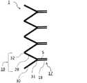
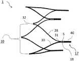
以下の説明において、本明細書の一部を形成し、具体的な実施形態又は実施例を実例として示す、添付の図面を参照する。図面への参照において、同様の数字は、複数の図にわたって同様の要素を表す。図1及び図2を参照すると、本明細書に開示されたリング1及び対応する支持アセンブリ10の側面図が、後に展開される端部であり得る本体12の近位端6に配置されて示されている。図1は、本体12と組立てらされたときのリング1の一実施形態のクローズアップ図であり、一方、図2は、例示的なリング1が本体12と組立てられたときの、更なる本体12を示す。本体12はまた、図6により明瞭に示すように、その近位端6と反対側の遠位端8(最初に展開される端としても既知)を含んでもよく、リング1は、遠位端8に機械的に接続されてもよい、及び/又は端6と8との間のいずれかの位置に配置されてもよいことを理解されたい。 In the following description, reference is made to the accompanying drawings that form a part hereof, and in which are shown by way of illustration specific embodiments or examples. In the drawings, like numerals represent like elements throughout the several views. Referring to FIGS. 1 and 2, a side view of the
図に示すように、図1及び図2の本体12は、複数の隙間24を形成するように編み組まれた又は別様に配列された複数の細長い部材22から形成されてもよい。部材22は、2つ若しくは3つ以上の金属ワイヤ、又は材料の高分子繊維若しくは撚線から形成されてもよい。リング1は、1つ又は2つ以上の付加的な半径方向力を内腔20の内壁及び/又は外壁に付与することが可能なリング1のフレームを一緒に形成する、1つ又は複数の相互接続支持アセンブリ10から構成されてもよい。この点に関して、リング1は、リング1を本体12自体に溶接、ハンダ付け、接着、又は別様に接続する必要なしに、本体12を急速に開き及び/又は本体12を開いた位置に維持するように、選択的に位置決め及び配列されてもよい。 As shown, the
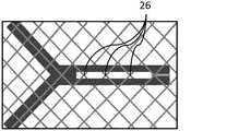
図2の平面A−Aのクローズアップ図である図3を参照すると、隙間24及び編み組まれた細長い部材22と絡み合わされた1つのアセンブリ10の例示的な爪17がより明瞭に示されている。図に示すように、アセンブリ10は、第1の交点31において第2の脚部30と接合された第1の脚部28を含んでもよい。脚部28及び30は、図3では互いに一体的に形成された状態で示されているが、各アセンブリ10は、そのように限定されず、脚部28及び30は、バンド、ボルト、クランプ、結合器、合釘、フック、ラッチ、キー、又は同様のものを含む締結具によって互いに取り外し可能に付着されてもよい。脚部28及び30はまた、互いに接着又は溶接されて交点31を形成してもよい。更に、1つ又は2つ以上の締結具が特定の実装に使用される場合、締結具は取り外し可能に接続若しくは溶接、ハンダ付け、及び/又は圧着されてもよい。締結具及び/又は脚部28及び30は、放射線不透過性金属、例えば、白金又はタンタルなどで形成され得るか、又は放射線透過性材料、例えば、ステンレス鋼などで形成されてもよい。 Referring to FIG. 3, which is a close-up view of plane AA of FIG. 2, the
爪17を各アセンブリ10の頂部の端に付加することによって、各リング1は、本体12への恒久的又は強固な付着、例えば、溶接、ハンダ付け、又は化学接着剤等を用いずに本体12と絡み合うことを可能にする。一旦爪17が、本体12及び所望の場所と効果的に絡み合わされて接続されると、編組部材22はまた、リング1から独立して動くことができ、それは、恒久的又は強固な付着が、従来、本体12に及ぼした悪影響を解消して、拡張リングと組立てられたときに完全に拡張する。 By adding a
交点31はまた、回転可能及び/又は捩れ可能な連結部を含むことにより、リング1の各アセンブリ10は、本体12及びリング1の使用中に、所定の量だけ曲がることが可能である。1つ又は2つ以上の細長い部材18は、交点31から延在し、交点31並びに脚部28及び30と反対側のロック機構40で終端してもよい。図3の実施形態では、複数の細長い部材18は、互いに実質的に整列しかつ互いからオフセットして示されており、同時に、機構40で接合されてそれらの間に空隙5を形成するように示されている。
本体12に機械的に付着するために、各爪17は、隙間24及び部材22を通過させられ、及び/又はそれらと絡み合わされ、次いで機構40で接合されるそれぞれの部材を有してもよい。この点で、部材22の1つ又は2つ以上の複数の編組対26が空隙5内に配列されるか、又は空隙と接続していることにより、爪17は、内腔20の内側及び外側の部分に機械的に付着され得る。図3の機構40は、部材18のそれぞれが互いに固定的に付着されるように、溶接、圧着、バンド結束、クランプ締め、又は接着によって形成されてもよい。 To mechanically adhere to the
図4A〜図4Cを参照すると、必要性又は選択に応じて必要とされるか又は要求されるときに使用され得る任意の数のアセンブリ10による複数のアセンブリ10を有するリング1の描写である。図4Aは、具体的に、第2の交点32で相互接続された2つの相互接続支持アセンブリ10を示し、脚部28がその交点から交点31に向かって延在する。図4Bは、同様に3つの相互接続アセンブリ10を示し、図4Cは、4つの相互接続アセンブリ10を示す。アセンブリ10は、交点32で互いに一体的に形成されてもよく、又は、本明細書で説明する締結具のうちのいずれかを使用して一緒に接合されてもよいことを理解されたい。各アセンブリ10は、図4Aが示す2つの圧縮要素、図4Bが示す3つの圧縮要素、及び図4Cが示す4つの圧縮要素のように所定の量だけ曲がることが可能な圧縮要素であってもよいことを理解されたい。これに関して、対応する圧縮要素を有するリング1は、脈管構造内での展開前の圧縮構成と、圧縮構成よりも大きい直径を有する内腔20を有する展開構成と、の間で動くことができる。それに加えて、交点31及び/又は32での各アセンブリ10の脚部28及び30は、図4A〜図4Cに示すようなV形状に形成されてもよく、脚部28と30との間に鋭角及び/又は傾斜が形成される。任意選択的に、V形状である代わりに、各アセンブリ10の脚部28及び30は、接合部分で「U」形状、楕円形状、略曲線形状、輪状又は湾曲状であるように形成されてもよい。 Referring to FIGS. 4A-4C, a depiction of a
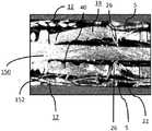
図5Aを参照すると、この図は、複数の相互接続アセンブリ10を有する例示的なリング1の斜視図である。各アセンブリ10は、図4A〜図4Cに示すようにV形状であってもよいが、図5Aは、各アセンブリ10が曲げられた向きにどのように配列され得るかを示す。この点で、脚部28及び/又は30は、圧縮に対する所定の抵抗力によって曲がる曲線状又はアーチ状の部分を含んでもよい。リング1の各アセンブリ10は、同じ又は異なる抵抗力を有することにより、各リング1が特定の脈管構造への実装に対して個別化され得ることを理解されたい。図5Bは、爪17の後方の本体12の横断面で圧縮状態にある本体12と組立てられたときの図5Aのリング1の例示の原型の前面図であり、脚部28及び30並びに本体12の内腔20のそれぞれを示す。各リング1を本体20の内面及び外面と位置決めして組立てるための送達機構150が、内腔20内に示されている。同様に、図5Cは、本体12と組立てられたときの図5Bのリング1の前面図であり、例示の送達機構50によって爪17の横断面で圧縮状態にあるそれ自体の内部の内腔20を示す。図に示すように、圧縮状態では、各リング1は、本体12の内面及び外面と組立てるように動作可能であり、同時にまた、外向きに拡張する半径方向力をステント本体に提供することにより、圧縮状態において内向きに加えられる圧縮力に対抗する。 Referring to FIG. 5A, this figure is a perspective view of an
各アセンブリ10及びそれ自体の構成特徴は、ニッケル−チタン合金又はニチノール等の超弾性材料から形成されてもよく、又は、ばね鋼若しくはMP35N(35重量%ニッケル、35重量%コバルト、20重量%クロム、及び10重量%モリブデンの合金)等の非超弾性材料から形成されてもよい。各アセンブリ10の脚部28及び30はまた、開いた状態で形状記憶位置を有する形状記憶材料から形成されてもよい。 Each
図6を参照すると、本体12の両端6及び8で組立てられているリング1の側面図が示されている。各アセンブリ10の爪17が、本体12の編組部材22と機械的に接続するように向けられ、一方、各アセンブリ10の反対側の交点32は、それぞれ、端6及び8と連絡していることがわかる。接合された脚部28及び30から形成される各アセンブリ10の交点32は、爪17と同様に、1つ又は2つ以上の部材22及び隙間24に機械的に接続されてもよいことも理解されたい。これに関して、交点32での脚部28及び30は、例えば、本体12自体に直接的に溶接又は締結されることによって本体12に直接的に付着する必要がない。代替として、交点31と同様に、脚部28及び/又は30は、隙間24のうちの1つ又は2つ以上を通過させられて、関連する部材22と絡み合わされることによって、直接的に一緒に接合され得、それぞれの交点31に向かって戻るように延在してもよい。 Referring to FIG. 6, a side view of the
図7は、部材22及び隙間24と絡み合わされた例示的な爪17を示す図6の平面B−Bのクローズアップ図である。より詳細には、脚部28及び30とは、交点31で一緒に接合され、それと共に、脚部28及び30のそれぞれが内腔20内に配置された状態であることがわかる。交点31で接合された後に、爪17は、交点31から機構40に向かって延在して空隙5を形成する複数の実質的に整列した細長い部材18を有してよい。機構40は、部材18のそれぞれを一緒に接合する前述の締結具のうちの任意のものを含んでもよく、又は、溶接、圧着、化学的接着、又は同等のものであってもよい。部材22の2つの編組対26は、空隙5を通過し、そのために、内腔20の内側及び外側の部分並びに本体12の部材24と絡み合わされていることもわかる。しかし、本明細書で開示された解決策は、そのように限定するのではなく、図9A〜図9Cに示すように、爪17の各部材18及び対応する空隙5は、様々な様式で部材22と編まれてもよい。例えば、1つの編組対26だけが、爪17の部材18及び空隙5と絡み合うことができ(図9A)、2つの編組対26が、爪17の部材18及び空隙5と絡み合うことができ(図9B)、及び/又は3つの編組対26が、爪17の部材18及び空隙5と絡み合うことができる(図9C)。図9A〜図9Cの部材18は、編組本体12に沿った同じ場所で編組対26に出入りし得る。 FIG. 7 is a close-up view of plane BB of FIG. 6 showing an
図8は、同様に、端6及び8に選択的に位置決めされたリング1、及び本体12の中心部分に沿って端6と8との間に配置されたリング1の側面図を示す。図8の実施形態は、限定することを意図しておらず、任意の数のリング1が端6と8との間に含まれてもよいことを理解されたい。 FIG. 8 similarly shows a side view of the
図10A〜図10Cを参照すると、本体12と組立てられたリング1の更なる例示的な側面図が示されている。具体的には、図10Aでは、3つの編組対26が、空隙5及び関連する部材18と絡み合わされて示され、この図では、爪17が編組本体12と絡み合ってそれに機械的に付着するときに、それぞれの編組対26に出入りする爪17の部分が示されている。対照的に、図10B及び図10Cの爪17は、3つの編組対26が空隙5と連通している場合であっても、図10Aの部材22及び隙間24の位置とは異なる位置で出入りする。 Referring to FIGS. 10A-10C, further exemplary side views of the
代替の爪設計は、リング1のアセンブリ10と共に使用することも企図される。例えば、図11Aでは、爪17aは、交点31aから延在してT形ロック機構40aで終端する単一の細長い部材18aだけを含み得ることがわかる。この実施形態では、爪17aは、交点31a上で編組対26と絡み合うことができ、本体12の多数の隙間24と絡み合うことができる機構40のT形部材で終端するまで本体12の外側部分に延在して、爪17aを本体12に機械的に接続する。図11Bの別の代替の実施形態では、爪17bが、交点31bとフック付き端のロック機構40bとの間に延在する複数の細長い部材18bと共に見ることができる。部材18bの一方又は両方は、部材22、及び1つ又は複数の編組対26と絡み合い、機構40bのフック付き部材で終端してもよい。機構40bのフック付き部材は、各部材18bを編組対26に機械的に固着させるように動作可能である、上方に延在したフック付き部分を有してもよい。機構40a及び40bの両方は、以前に開示された機構40の溶接、接着、圧着、又は締結具の代わりに使用されてもよい。 Alternative claw designs are also contemplated for use with the
図12A及び図12Bを参照すると、各図面は、本体12と組立てられたときの例示の爪17の原型の、爪17の長手方向断面に沿った側面図を示す。図12A及び図12Bのそれぞれに示すように、機構150及び対応する隆起部152は、部材18及び対応する間隙5を1つ又は2つ以上の部材22及び/又は対26と位置決めし得る。図12A及び図12Bは、限定することを意図しておらず、爪17及び/又はその構成特徴は、必要又は所望に応じて、機構150の有無に関わらず本体12と組立てられてもよい。 Referring to FIGS. 12A and 12B, each drawing shows a side view along the longitudinal cross-section of the
特定の構成、材料選択、並びに様々な要素のサイズ及び形状は、開示された技術の原理に従って構成されたシステム又は方法を必要とする特定の設計仕様書若しくは制約に従って変化し得る。そのような変更は、開示された技術の範囲内に包含される。したがって、本開示の実施形態は、あらゆる点において、例示的であり、限定的ではないと見なされる。したがって、以上のことから、開示の特定の形態を図示し説明したが、開示の趣旨及び範囲から逸脱せずに種々の修正を行うことができ、その等価物の意味及び範囲内にある全ての変更が含まれることは明らかである。 The particular configuration, material selection, and the size and shape of the various elements may vary according to particular design specifications or constraints that require a system or method constructed in accordance with the principles of the disclosed technology. Such modifications are encompassed within the scope of the disclosed technology. Accordingly, the embodiments of the present disclosure are considered in all respects as illustrative and not restrictive. Accordingly, while the particular forms of the disclosure have been illustrated and described, various modifications can be made without departing from the spirit and scope of the disclosure, and all equivalents and equivalents within the meaning and scope of the disclosure can be made. Clearly, changes are included.
〔実施の態様〕
(1) 編組ステントシステムであって、
複数の編組部材によって形成された内腔を有し、前記複数の編組部材の間に隙間が形成されたステント本体と、
前記ステント本体の前記内腔に機械的に接続された拡張リングであって、外向きに拡張する半径方向力を前記ステント本体に付与するフレームを備え、前記フレームは、第1の交点で接合された複数の脚部と、前記ステント本体の前記隙間のうちの1つ又は2つ以上に機械的に接続された爪部分と、を備える、拡張リングと、を備える、システム。
(2) 前記爪部分は、複数の前記隙間を通って前記第1の交点から離れる方向に延在することと、前記第1の交点と反対側のロック機構で終端することと、によって、前記拡張リングを前記隙間のうちの1つ又は2つ以上に機械的に接続する、実施態様1に記載のシステム。
(3) 前記爪部分は、前記第1の交点と前記ロック機構との間に延在して、前記複数の隙間が通過する空隙を形成する、少なくとも2つの整列した細長い部材を備える、実施態様2に記載のシステム。
(4) 前記フレームの前記複数の脚部が曲げられて、前記フレームを圧縮に対して抵抗性にし、前記脚部は、前記第1の交点の周りで所定の量だけ捩れ可能である、実施態様1に記載のシステム。
(5) 編組ステントシステムであって、
複数の編組部材によって形成された内腔を有し、前記複数の編組部材の間に隙間が形成されたステント本体と、
前記ステント本体の前記内腔に接続された第1の拡張リングであって、外向きに拡張する半径方向力を前記ステント本体に付与するように選択的に位置決めされた複数の相互接続支持アセンブリによって画定されたフレームを備え、各支持アセンブリは、
第1の交点で接合され、かつ前記第1の交点と反対側の第2の交点で他の相互接続支持アセンブリのうちの1つに接続された複数の脚部と、
前記ステント本体の前記隙間のうちの1つ又は2つ以上に機械的に接続された爪部分と、を備える、第1の拡張リングと、を備える、システム。Embodiment
(1) A braided stent system,
A stent body having a lumen formed by a plurality of braided members, wherein a gap is formed between the plurality of braided members;
An expansion ring mechanically connected to the lumen of the stent body, the frame including a frame that applies an outwardly expanding radial force to the stent body, the frame being joined at a first intersection. An expansion ring comprising a plurality of legs and a claw portion mechanically connected to one or more of the gaps of the stent body.
(2) The claw portion extends in a direction away from the first intersection through a plurality of the gaps, and terminates with a locking mechanism on the opposite side to the first intersection. The system of
(3) The embodiment wherein the claw portion comprises at least two aligned elongated members extending between the first intersection and the locking mechanism to form a gap through which the plurality of gaps pass. 2. The system according to 2.
(4) The plurality of legs of the frame are bent to make the frame resistant to compression, and the legs are twistable by a predetermined amount around the first intersection. The system according to
(5) a braided stent system,
A stent body having a lumen formed by a plurality of braided members, wherein a gap is formed between the plurality of braided members;
A first expansion ring connected to the lumen of the stent body by a plurality of interconnect support assemblies selectively positioned to apply an outwardly expanding radial force to the stent body. Each support assembly includes a defined frame;
A plurality of legs joined at a first intersection and connected to one of the other interconnect support assemblies at a second intersection opposite the first intersection;
A first expansion ring comprising a claw portion mechanically connected to one or more of the gaps of the stent body.
(6) 前記フレームの前記複数の脚部が曲げられて、前記フレームを圧縮に対して抵抗性にし、前記脚部は、前記第1及び第2の交点の周りで捩れ可能である、実施態様5に記載のシステム。
(7) 前記爪部分は、前記第1の交点から離れる方向に延在することと、前記隙間のうちの少なくとも2つを通して絡み合わされることと、前記交点と反対側のロック機構で終端していることと、によって、前記拡張リングを前記内腔の内側部分及び外側部分に機械的に接続する、実施態様5に記載のシステム。
(8) 前記ロック機構は、前記ステント本体の前記隙間に固定的に接続するように動作可能なT形端部又は外向きに延在するフック付き部材のうちの一方を含む、実施態様7に記載のシステム。
(9) 前記爪部分のうちの少なくとも1つは、それぞれの第1の交点とロック機構との間に延在して、前記複数の隙間が通過する空隙を形成する、複数の整列した細長い部材を備える、実施態様7に記載のシステム。
(10) 前記編組部材の複数の編組対が、前記空隙を通過する、実施態様9に記載のシステム。(6) The embodiment wherein the plurality of legs of the frame are bent to make the frame resistant to compression, and the legs are twistable about the first and second intersections. 5. The system according to 5.
(7) The claw portion extends in a direction away from the first intersection, is entangled through at least two of the gaps, and terminates with a lock mechanism on the opposite side of the intersection.
(8) In embodiment 7, the locking mechanism includes one of a T-shaped end portion operable to be fixedly connected to the gap of the stent body or an outwardly hooked member. The described system.
(9) A plurality of aligned elongated members wherein at least one of the claw portions extends between a respective first intersection and a locking mechanism to form a gap through which the plurality of gaps pass.
(10) The system according to embodiment 9, wherein a plurality of braid pairs of the braid members pass through the gap.
(11) 前記ロック機構は、前記第1の交点と反対側の前記整列した細長い部材の端部を、溶接、ハンダ付け、圧着、又は接着剤により接合することによって、前記拡張リングを前記ステント本体に固定的に接続する、実施態様9に記載のシステム。
(12) 前記ロック機構は、前記第1の交点と反対側の前記整列した細長い部材の端部を、金属製バンド又はリングにより接合することによって、前記拡張リングを前記ステント本体に固定的に接続する、実施態様9に記載のシステム。
(13) 前記第2の交点のうちの少なくとも1つは、V形状、U形状、又は楕円曲線のうちの少なくとも1つを形成する、実施態様5に記載のシステム。
(14) 前記第1の交点のうちの少なくとも1つは、V形状、U形状、又は楕円曲線を形成する、実施態様5に記載のシステム。
(15) 前記ステント本体は、近位端と、遠位端と、それらの間に配置された中心部分と、を含み、前記第1の拡張リングは、前記ステント本体の前記遠位端若しくは前記近位端に又はそれに隣接して配置され、前記相互接続支持アセンブリの前記第2の交点は、それぞれの前記遠位端若しくは前記近位端で又はそれに隣接して接合されている、実施態様5に記載のシステム。(11) The locking mechanism connects the end of the aligned elongated member opposite to the first intersection point by welding, soldering, crimping, or an adhesive, thereby connecting the expansion ring to the stent body.
(12) The locking mechanism is configured to fixally connect the expansion ring to the stent body by joining ends of the aligned elongated members opposite to the first intersection with a metal band or ring.
(13) The system of
(14) The system of
(15) The stent body includes a proximal end, a distal end, and a central portion disposed therebetween, wherein the first expansion ring is the distal end of the stent body or the
(16) 前記ステント本体の前記中心部分に沿って前記内腔に接続された第2の拡張リングを更に備え、前記第2の拡張リングは、バランスの取れた外向きに拡張する半径方向力を前記ステント本体に付与するように選択的に位置決めされた複数の相互接続支持アセンブリによって画定されたフレームを備え、各支持アセンブリは、第1の交点で接合され、かつ前記第1の交点と反対側の第2の交点で他の相互接続支持アセンブリのうちの1つに接続された複数の脚部と、前記ステント本体の前記隙間のうちの1つ又は2つ以上に機械的に接続された爪部分と、を備える、実施態様15に記載のシステム。
(17) 編組ステント本体を脈管の中に展開させる方法であって、
複数の拡張リングを前記編組ステント本体の内腔に組立てることであって、前記編組ステント本体の前記内腔は、複数の編組部材によって形成され、前記複数の編組部材の間に隙間が形成される、組立てることと、
各拡張リングを前記編組ステント本体と共に選択的に位置決めすることであって、
各拡張リングが、外向きに拡張する半径方向力を付与することにより、前記編組ステント本体の前記内腔を開いた位置に維持し、各拡張リングが、第1の交点で接合され、かつ前記第1の交点と反対側の第2の交点で他の相互接続支持アセンブリのうちの1つに接続された複数の脚部であって、前記第1及び第2の交点の周りで捩れ可能である、複数の脚部と、前記第1及び第2の交点と反対側に配置された爪部分と、を備える複数の相互接続支持アセンブリによって画定されたフレームを備える、位置決めすることと、
前記拡張リングのそれぞれの爪部分とそれぞれの第1の交点との間に延在し、かつ前記交点と反対側のロック機構で終端した第1の細長い部材を前記隙間のうちの1つ又は2つ以上と絡み合わせることによって、各リングの前記爪部分を前記ステント本体の内側部分に機械的に接続することと、
前記編組部材を各拡張リングから独立して前記脈管内で並進させることと、を含む、方法。
(18) 各拡張リングの前記脚部を曲げて、各リングを圧縮に対して抵抗性にすることを更に含む、実施態様17に記載の方法。
(19) 前記爪部分のうちの少なくとも1つは、前記第1の細長い部材と実質的に整列し、かつそれぞれの第1の交点とロック機構との間に延在した第2の整列部材を備え、前記方法は、前記第1及び第2の細長い部材と、それぞれの第1の交点及びロック機構との間に空隙を形成することと、前記編組部材の複数の編組対を前記空隙に通過させることと、を更に含む、実施態様17に記載の方法。
(20) 前記第1の交点と反対側の前記第1の細長い部材及び前記第2の細長い部材の端部を、溶接、ハンダ付け、圧着、接着剤、又は締結具により接合することによって、前記拡張リングを前記ステント本体に固定的に接続することを更に含む、実施態様19に記載の方法。(16) further comprising a second expansion ring connected to the lumen along the central portion of the stent body, the second expansion ring having a radially outwardly expanding radial force; A frame defined by a plurality of interconnect support assemblies selectively positioned to be applied to the stent body, each support assembly being joined at a first intersection and opposite the first intersection A plurality of legs connected to one of the other interconnect support assemblies at a second intersection of the nail and a nail mechanically connected to one or more of the gaps in the stent body 16. The system of embodiment 15, comprising: a portion.
(17) A method of deploying a braided stent body into a vessel,
Assembling a plurality of expansion rings into the lumen of the braided stent body, wherein the lumen of the braided stent body is formed by a plurality of braid members, and a gap is formed between the plurality of braid members. Assembling,
Selectively positioning each expansion ring with the braided stent body,
Each expansion ring applies an outwardly expanding radial force to maintain the lumen of the braided stent body in an open position, each expansion ring being joined at a first intersection, and A plurality of legs connected to one of the other interconnect support assemblies at a second intersection point opposite the first intersection point, and capable of being twisted about the first and second intersection points Positioning comprising a frame defined by a plurality of interconnect support assemblies comprising a plurality of legs and a pawl portion disposed opposite the first and second intersections;
One or two of the gaps may be a first elongate member extending between each pawl portion of the expansion ring and a respective first intersection and terminated with a locking mechanism opposite the intersection. Mechanically connecting the claw portion of each ring to the inner portion of the stent body by intertwining with one or more;
Translating the braided member within the vessel independently of each expansion ring.
18. The method of
(19) At least one of the pawl portions includes a second alignment member that is substantially aligned with the first elongated member and that extends between the respective first intersection and the locking mechanism. And the method includes forming a gap between the first and second elongated members and respective first intersections and locking mechanisms and passing a plurality of braid pairs of the braided member through the gap. 18. The method of
(20) By joining the ends of the first elongated member and the second elongated member opposite to the first intersection by welding, soldering, crimping, an adhesive, or a fastener, 20. The method of
Claims (16)
Translated fromJapanese複数の編組部材によって形成された内腔を有し、前記複数の編組部材の間に隙間が形成されたステント本体と、
前記ステント本体の前記内腔に機械的に接続された拡張リングであって、外向きに拡張する半径方向力を前記ステント本体に付与するフレームを備え、前記フレームは、第1の交点で接合された複数の脚部と、前記ステント本体の前記隙間のうちの1つ又は2つ以上に機械的に接続された爪部分と、を備える、拡張リングと、を備える、システム。A braided stent system,
A stent body having a lumen formed by a plurality of braided members, wherein a gap is formed between the plurality of braided members;
An expansion ring mechanically connected to the lumen of the stent body, the frame including a frame that applies an outwardly expanding radial force to the stent body, the frame being joined at a first intersection. An expansion ring comprising a plurality of legs and a claw portion mechanically connected to one or more of the gaps of the stent body.
複数の編組部材によって形成された内腔を有し、前記複数の編組部材の間に隙間が形成されたステント本体と、
前記ステント本体の前記内腔に接続された第1の拡張リングであって、外向きに拡張する半径方向力を前記ステント本体に付与するように選択的に位置決めされた複数の相互接続支持アセンブリによって画定されたフレームを備え、各支持アセンブリは、
第1の交点で接合され、かつ前記第1の交点と反対側の第2の交点で他の相互接続支持アセンブリのうちの1つに接続された複数の脚部と、
前記ステント本体の前記隙間のうちの1つ又は2つ以上に機械的に接続された爪部分と、を備える、第1の拡張リングと、を備える、システム。A braided stent system,
A stent body having a lumen formed by a plurality of braided members, wherein a gap is formed between the plurality of braided members;
A first expansion ring connected to the lumen of the stent body by a plurality of interconnect support assemblies selectively positioned to apply an outwardly expanding radial force to the stent body. Each support assembly includes a defined frame;
A plurality of legs joined at a first intersection and connected to one of the other interconnect support assemblies at a second intersection opposite the first intersection;
A first expansion ring comprising a claw portion mechanically connected to one or more of the gaps of the stent body.
Applications Claiming Priority (2)
| Application Number | Priority Date | Filing Date | Title |
|---|---|---|---|
| US15/299,918US10182927B2 (en) | 2016-10-21 | 2016-10-21 | Expansion ring for a braided stent |
| US15/299,918 | 2016-10-21 |
Publications (2)
| Publication Number | Publication Date |
|---|---|
| JP2018064943Atrue JP2018064943A (en) | 2018-04-26 |
| JP6968655B2 JP6968655B2 (en) | 2021-11-17 |
Family
ID=60182367
Family Applications (1)
| Application Number | Title | Priority Date | Filing Date |
|---|---|---|---|
| JP2017204234AActiveJP6968655B2 (en) | 2016-10-21 | 2017-10-23 | Expansion ring for braided stents |
Country Status (9)
| Country | Link |
|---|---|
| US (3) | US10182927B2 (en) |
| EP (2) | EP3656358B1 (en) |
| JP (1) | JP6968655B2 (en) |
| KR (1) | KR102486606B1 (en) |
| CN (1) | CN107970082B (en) |
| AU (1) | AU2017235961A1 (en) |
| BR (1) | BR102017022498A2 (en) |
| CA (1) | CA2982092A1 (en) |
| ES (2) | ES2774061T3 (en) |
Cited By (1)
| Publication number | Priority date | Publication date | Assignee | Title |
|---|---|---|---|---|
| JP2023526065A (en)* | 2020-05-20 | 2023-06-20 | オックスフォード エンドバスキュラー リミテッド | Expandable tube for intravascular deployment |
Families Citing this family (12)
| Publication number | Priority date | Publication date | Assignee | Title |
|---|---|---|---|---|
| US10561509B2 (en) | 2013-03-13 | 2020-02-18 | DePuy Synthes Products, Inc. | Braided stent with expansion ring and method of delivery |
| US10206796B2 (en) | 2014-08-27 | 2019-02-19 | DePuy Synthes Products, Inc. | Multi-strand implant with enhanced radiopacity |
| US10076428B2 (en)* | 2016-08-25 | 2018-09-18 | DePuy Synthes Products, Inc. | Expansion ring for a braided stent |
| US10292851B2 (en) | 2016-09-30 | 2019-05-21 | DePuy Synthes Products, Inc. | Self-expanding device delivery apparatus with dual function bump |
| US11382635B2 (en) | 2018-07-06 | 2022-07-12 | Boston Scientific Scimed, Inc. | Occlusive medical device |
| AU2019204522A1 (en) | 2018-07-30 | 2020-02-13 | DePuy Synthes Products, Inc. | Systems and methods of manufacturing and using an expansion ring |
| US10456280B1 (en) | 2018-08-06 | 2019-10-29 | DePuy Synthes Products, Inc. | Systems and methods of using a braided implant |
| US10278848B1 (en) | 2018-08-06 | 2019-05-07 | DePuy Synthes Products, Inc. | Stent delivery with expansion assisting delivery wire |
| CN111265278B (en)* | 2018-12-04 | 2023-02-07 | 先健科技(深圳)有限公司 | Thrombectomy Devices and Thrombectomy Systems |
| US11039944B2 (en) | 2018-12-27 | 2021-06-22 | DePuy Synthes Products, Inc. | Braided stent system with one or more expansion rings |
| CN113069255B (en)* | 2019-12-17 | 2023-04-18 | 先健科技(深圳)有限公司 | Blood vessel support |
| WO2022174185A1 (en)* | 2021-02-15 | 2022-08-18 | Shipp John I | Stent |
Family Cites Families (99)
| Publication number | Priority date | Publication date | Assignee | Title |
|---|---|---|---|---|
| US4610688A (en)* | 1983-04-04 | 1986-09-09 | Pfizer Hospital Products Group, Inc. | Triaxially-braided fabric prosthesis |
| US5545208A (en)* | 1990-02-28 | 1996-08-13 | Medtronic, Inc. | Intralumenal drug eluting prosthesis |
| US5064435A (en)* | 1990-06-28 | 1991-11-12 | Schneider (Usa) Inc. | Self-expanding prosthesis having stable axial length |
| US5330500A (en)* | 1990-10-18 | 1994-07-19 | Song Ho Y | Self-expanding endovascular stent with silicone coating |
| US6051020A (en)* | 1994-02-09 | 2000-04-18 | Boston Scientific Technology, Inc. | Bifurcated endoluminal prosthesis |
| US5609627A (en)* | 1994-02-09 | 1997-03-11 | Boston Scientific Technology, Inc. | Method for delivering a bifurcated endoluminal prosthesis |
| US6165213A (en)* | 1994-02-09 | 2000-12-26 | Boston Scientific Technology, Inc. | System and method for assembling an endoluminal prosthesis |
| DE69507800T2 (en)* | 1994-05-19 | 1999-07-22 | Scimed Life Systems, Inc., Maple Grove, Minn. | IMPROVED TISSUE SUPPORTS |
| US5476508A (en)* | 1994-05-26 | 1995-12-19 | Tfx Medical | Stent with mutually interlocking filaments |
| US5549662A (en)* | 1994-11-07 | 1996-08-27 | Scimed Life Systems, Inc. | Expandable stent using sliding members |
| EP0790810B1 (en)* | 1994-11-09 | 2004-04-28 | Endotex Interventional Systems, Inc. | Kit of delivery catheter and graft for aneurysm repair |
| DE19508805C2 (en)* | 1995-03-06 | 2000-03-30 | Lutz Freitag | Stent for placement in a body tube with a flexible support structure made of at least two wires with different shape memory functions |
| BE1009277A3 (en)* | 1995-04-12 | 1997-01-07 | Corvita Europ | Guardian self-expandable medical device introduced in cavite body, and method of preparation. |
| US5728131A (en)* | 1995-06-12 | 1998-03-17 | Endotex Interventional Systems, Inc. | Coupling device and method of use |
| US6193745B1 (en)* | 1995-10-03 | 2001-02-27 | Medtronic, Inc. | Modular intraluminal prosteheses construction and methods |
| US5776161A (en)* | 1995-10-16 | 1998-07-07 | Instent, Inc. | Medical stents, apparatus and method for making same |
| ATE290832T1 (en)* | 1996-01-05 | 2005-04-15 | Medtronic Inc | EXPANDABLE ENDOLUMINAL PROSTHESES |
| US6010529A (en)* | 1996-12-03 | 2000-01-04 | Atrium Medical Corporation | Expandable shielded vessel support |
| ATE306873T1 (en)* | 1997-01-24 | 2005-11-15 | Kentucky Oil N V | BISTABLE SPRING STRUCTURE FOR A STENT |
| US6152956A (en)* | 1997-01-28 | 2000-11-28 | Pierce; George E. | Prosthesis for endovascular repair of abdominal aortic aneurysms |
| US5817126A (en)* | 1997-03-17 | 1998-10-06 | Surface Genesis, Inc. | Compound stent |
| DE19720115C2 (en)* | 1997-05-14 | 1999-05-20 | Jomed Implantate Gmbh | Stent graft |
| US5899935A (en)* | 1997-08-04 | 1999-05-04 | Schneider (Usa) Inc. | Balloon expandable braided stent with restraint |
| US6033436A (en)* | 1998-02-17 | 2000-03-07 | Md3, Inc. | Expandable stent |
| US6015432A (en)* | 1998-02-25 | 2000-01-18 | Cordis Corporation | Wire reinforced vascular prosthesis |
| WO2000033769A1 (en)* | 1998-12-11 | 2000-06-15 | Endologix, Inc. | Endoluminal vascular prosthesis |
| US6325823B1 (en)* | 1999-10-29 | 2001-12-04 | Revasc Corporation | Endovascular prosthesis accommodating torsional and longitudinal displacements and methods of use |
| US6673107B1 (en)* | 1999-12-06 | 2004-01-06 | Advanced Cardiovascular Systems, Inc. | Bifurcated stent and method of making |
| GB0003387D0 (en)* | 2000-02-14 | 2000-04-05 | Angiomed Ag | Stent matrix |
| US6319278B1 (en)* | 2000-03-03 | 2001-11-20 | Stephen F. Quinn | Low profile device for the treatment of vascular abnormalities |
| US6929658B1 (en)* | 2000-03-09 | 2005-08-16 | Design & Performance-Cyprus Limited | Stent with cover connectors |
| US6565599B1 (en)* | 2000-12-28 | 2003-05-20 | Advanced Cardiovascular Systems, Inc. | Hybrid stent |
| US6540777B2 (en)* | 2001-02-15 | 2003-04-01 | Scimed Life Systems, Inc. | Locking stent |
| US6761733B2 (en)* | 2001-04-11 | 2004-07-13 | Trivascular, Inc. | Delivery system and method for bifurcated endovascular graft |
| US6733521B2 (en)* | 2001-04-11 | 2004-05-11 | Trivascular, Inc. | Delivery system and method for endovascular graft |
| US6821291B2 (en)* | 2001-06-01 | 2004-11-23 | Ams Research Corporation | Retrievable stent and method of use thereof |
| JP4043216B2 (en)* | 2001-10-30 | 2008-02-06 | オリンパス株式会社 | Stent |
| US7708771B2 (en)* | 2002-02-26 | 2010-05-04 | Endovascular Technologies, Inc. | Endovascular graft device and methods for attaching components thereof |
| US7105018B1 (en)* | 2002-12-30 | 2006-09-12 | Advanced Cardiovascular Systems, Inc. | Drug-eluting stent cover and method of use |
| US7235093B2 (en)* | 2003-05-20 | 2007-06-26 | Boston Scientific Scimed, Inc. | Mechanism to improve stent securement |
| US20050033406A1 (en)* | 2003-07-15 | 2005-02-10 | Barnhart William H. | Branch vessel stent and graft |
| US7122052B2 (en)* | 2003-09-29 | 2006-10-17 | Stout Medical Group Lp | Integral support stent graft assembly |
| US20070219613A1 (en)* | 2003-10-06 | 2007-09-20 | Xtent, Inc. | Apparatus and methods for interlocking stent segments |
| US8157855B2 (en)* | 2003-12-05 | 2012-04-17 | Boston Scientific Scimed, Inc. | Detachable segment stent |
| FR2865926B1 (en)* | 2004-02-11 | 2006-05-12 | Perouse Laboratoires | TUBULAR PROSTHESIS. |
| US7695506B2 (en) | 2004-09-21 | 2010-04-13 | Boston Scientific Scimed, Inc. | Atraumatic connections for multi-component stents |
| US20060069424A1 (en)* | 2004-09-27 | 2006-03-30 | Xtent, Inc. | Self-constrained segmented stents and methods for their deployment |
| WO2006065665A1 (en)* | 2004-12-13 | 2006-06-22 | Robert Hunt Carpenter, Dvm, Pc | Multi-wall expandable device capable of drug delivery |
| US8128680B2 (en)* | 2005-01-10 | 2012-03-06 | Taheri Laduca Llc | Apparatus and method for deploying an implantable device within the body |
| US8002818B2 (en)* | 2005-02-25 | 2011-08-23 | Abbott Laboratories Vascular Enterprises Limited | Modular vascular prosthesis having axially variable properties and improved flexibility and methods of use |
| US8025694B2 (en)* | 2005-02-25 | 2011-09-27 | Abbott Laboratories Vascular Enterprises Limited | Modular vascular prosthesis and methods of use |
| US20070213810A1 (en)* | 2005-03-14 | 2007-09-13 | Richard Newhauser | Segmented endoprosthesis |
| JP4912395B2 (en)* | 2005-05-24 | 2012-04-11 | エドワーズ ライフサイエンシーズ コーポレイション | Rapid placement prosthetic heart valve |
| US20070005127A1 (en)* | 2005-06-17 | 2007-01-04 | Peter Boekstegers | Hinged tissue implant and related methods and devices for delivering such an implant |
| US9149378B2 (en)* | 2005-08-02 | 2015-10-06 | Reva Medical, Inc. | Axially nested slide and lock expandable device |
| FR2894131B1 (en)* | 2005-12-02 | 2008-12-05 | Perouse Soc Par Actions Simpli | DEVICE FOR TREATING A BLOOD VESSEL, AND ASSOCIATED TREATMENT NECESSARY. |
| EP1988851A2 (en)* | 2006-02-14 | 2008-11-12 | Sadra Medical, Inc. | Systems and methods for delivering a medical implant |
| US20070208409A1 (en)* | 2006-03-01 | 2007-09-06 | Boston Scientific Scimed, Inc. | Flexible stent-graft devices and methods of producing the same |
| US20100010622A1 (en)* | 2006-03-13 | 2010-01-14 | Abbott Laboratories | Hybrid segmented endoprosthesis |
| WO2007109621A2 (en)* | 2006-03-20 | 2007-09-27 | Xtent, Inc. | Apparatus and methods for deployment of linked prosthetic segments |
| FR2899096B1 (en)* | 2006-04-04 | 2008-12-05 | Perouse Soc Par Actions Simpli | DEVICE FOR TREATING A CIRCULATION CIRCULATION OF THE BLOOD AND METHOD OF PREPARING SAID DEVICE |
| EP1849440A1 (en)* | 2006-04-28 | 2007-10-31 | Younes Boudjemline | Vascular stents with varying diameter |
| WO2008047369A2 (en)* | 2006-10-18 | 2008-04-24 | Inspiremd Ltd. | Knitted stent jackets |
| EP2116213B1 (en)* | 2007-02-01 | 2017-03-29 | Kaneka Corporation | Medical device for body cavity and method of producing the same |
| US20080221670A1 (en)* | 2007-03-07 | 2008-09-11 | Claude Clerc | Radiopaque polymeric stent |
| WO2009002819A2 (en)* | 2007-06-22 | 2008-12-31 | Cr Bard Inc. | Locked segments pushable stent-graft |
| US20090082845A1 (en)* | 2007-09-26 | 2009-03-26 | Boston Scientific Corporation | Alignment stent apparatus and method |
| US8066755B2 (en)* | 2007-09-26 | 2011-11-29 | Trivascular, Inc. | System and method of pivoted stent deployment |
| US20090082847A1 (en)* | 2007-09-26 | 2009-03-26 | Boston Scientific Corporation | System and method of securing stent barbs |
| US20090163951A1 (en)* | 2007-12-19 | 2009-06-25 | Sara Simmons | Medical devices including sutures with filaments comprising naturally derived collagenous material |
| US20090192588A1 (en)* | 2008-01-29 | 2009-07-30 | Taeoong Medical Co., Ltd | Biodegradable double stent |
| US7815673B2 (en)* | 2008-04-01 | 2010-10-19 | Medtronic Vascular, Inc. | Double-walled stent system |
| US20090287145A1 (en)* | 2008-05-15 | 2009-11-19 | Altura Interventional, Inc. | Devices and methods for treatment of abdominal aortic aneurysms |
| US8414639B2 (en)* | 2008-07-08 | 2013-04-09 | Boston Scientific Scimed, Inc. | Closed-cell flexible stent hybrid |
| US8308798B2 (en)* | 2008-12-19 | 2012-11-13 | Edwards Lifesciences Corporation | Quick-connect prosthetic heart valve and methods |
| US20100292777A1 (en)* | 2009-05-13 | 2010-11-18 | Boston Scientific Scimed, Inc. | Stent |
| US8348998B2 (en)* | 2009-06-26 | 2013-01-08 | Edwards Lifesciences Corporation | Unitary quick connect prosthetic heart valve and deployment system and methods |
| DE102009041025A1 (en)* | 2009-09-14 | 2011-03-24 | Acandis Gmbh & Co. Kg | Medical implant |
| CN102100587B (en)* | 2009-12-18 | 2013-10-30 | 上海微创医疗器械(集团)有限公司 | Blood vessel bracket prosthesis |
| CA2788111C (en)* | 2010-01-29 | 2016-04-05 | Cook Medical Technologies Llc | Collapsing structure for reducing the diameter of a stent |
| US9326870B2 (en)* | 2010-04-23 | 2016-05-03 | Medtronic Vascular, Inc. | Biodegradable stent having non-biodegradable end portions and mechanisms for increased stent hoop strength |
| US20130041454A1 (en)* | 2011-02-09 | 2013-02-14 | Business Expectations Llc | Sensor Actuated Stent |
| EP4566553A3 (en)* | 2011-03-09 | 2025-08-06 | Neuravi Limited | A clot retrieval device for removing occlusive clot from a blood vessel |
| US9655722B2 (en)* | 2011-10-19 | 2017-05-23 | Twelve, Inc. | Prosthetic heart valve devices, prosthetic mitral valves and associated systems and methods |
| US20130123901A1 (en)* | 2011-11-14 | 2013-05-16 | Robert A. Connor | Stent with in situ determination of wall areas with differences in porosity |
| CN110464520A (en)* | 2012-01-25 | 2019-11-19 | 因特脉管有限公司 | Intracavitary unit and method |
| WO2013151793A1 (en) | 2012-04-06 | 2013-10-10 | Trivascular, Inc. | Low profile stent graft and delivery system |
| US8968387B2 (en)* | 2012-07-23 | 2015-03-03 | Abbott Cardiovascular Systems Inc. | Shape memory bioresorbable polymer peripheral scaffolds |
| US9034028B2 (en)* | 2013-03-13 | 2015-05-19 | DePuy Synthes Products, Inc. | Braid expansion ring with markers |
| US10561509B2 (en)* | 2013-03-13 | 2020-02-18 | DePuy Synthes Products, Inc. | Braided stent with expansion ring and method of delivery |
| US9907684B2 (en)* | 2013-05-08 | 2018-03-06 | Aneuclose Llc | Method of radially-asymmetric stent expansion |
| US10646333B2 (en)* | 2013-10-24 | 2020-05-12 | Medtronic, Inc. | Two-piece valve prosthesis with anchor stent and valve component |
| US9763778B2 (en)* | 2014-03-18 | 2017-09-19 | St. Jude Medical, Cardiology Division, Inc. | Aortic insufficiency valve percutaneous valve anchoring |
| US10195025B2 (en)* | 2014-05-12 | 2019-02-05 | Edwards Lifesciences Corporation | Prosthetic heart valve |
| WO2017126620A1 (en)* | 2016-01-19 | 2017-07-27 | 株式会社ジェイ・エム・エス | Synthetic resin stent |
| US10758381B2 (en)* | 2016-03-31 | 2020-09-01 | Vesper Medical, Inc. | Intravascular implants |
| JP6963566B2 (en)* | 2016-05-16 | 2021-11-10 | エリクシアー メディカル コーポレイション | Uncaging stent |
| GB201616777D0 (en)* | 2016-10-03 | 2016-11-16 | Univ Southampton | A frame for an implantable medical device and a method of manufacturing a frame for an implantable medical device |
| US10722353B2 (en)* | 2017-08-21 | 2020-07-28 | Edwards Lifesciences Corporation | Sealing member for prosthetic heart valve |
- 2016
- 2016-10-21USUS15/299,918patent/US10182927B2/enactiveActive
- 2017
- 2017-09-28AUAU2017235961Apatent/AU2017235961A1/ennot_activeAbandoned
- 2017-10-11CACA2982092Apatent/CA2982092A1/enactivePending
- 2017-10-19BRBR102017022498-8Apatent/BR102017022498A2/ennot_activeApplication Discontinuation
- 2017-10-20CNCN201710981691.1Apatent/CN107970082B/enactiveActive
- 2017-10-20KRKR1020170136448Apatent/KR102486606B1/enactiveActive
- 2017-10-20EPEP19214993.8Apatent/EP3656358B1/enactiveActive
- 2017-10-20ESES17197578Tpatent/ES2774061T3/enactiveActive
- 2017-10-20EPEP17197578.2Apatent/EP3311782B1/enactiveActive
- 2017-10-20ESES19214993Tpatent/ES2923948T3/enactiveActive
- 2017-10-23JPJP2017204234Apatent/JP6968655B2/enactiveActive
- 2018
- 2018-12-27USUS16/234,270patent/US20190125557A1/ennot_activeAbandoned
- 2020
- 2020-10-21USUS17/076,053patent/US20210038412A1/ennot_activeAbandoned
Cited By (2)
| Publication number | Priority date | Publication date | Assignee | Title |
|---|---|---|---|---|
| JP2023526065A (en)* | 2020-05-20 | 2023-06-20 | オックスフォード エンドバスキュラー リミテッド | Expandable tube for intravascular deployment |
| JP7736716B2 (en) | 2020-05-20 | 2025-09-09 | オックスフォード エンドバスキュラー リミテッド | Expandable tube for intravascular deployment - Patent Application 20070122997 |
Also Published As
| Publication number | Publication date |
|---|---|
| US20210038412A1 (en) | 2021-02-11 |
| KR20180044210A (en) | 2018-05-02 |
| EP3656358A1 (en) | 2020-05-27 |
| US10182927B2 (en) | 2019-01-22 |
| ES2923948T3 (en) | 2022-10-03 |
| CN107970082B (en) | 2021-10-29 |
| KR102486606B1 (en) | 2023-01-11 |
| BR102017022498A2 (en) | 2018-05-02 |
| EP3311782A1 (en) | 2018-04-25 |
| EP3311782B1 (en) | 2019-12-11 |
| CN107970082A (en) | 2018-05-01 |
| ES2774061T3 (en) | 2020-07-16 |
| AU2017235961A1 (en) | 2018-05-10 |
| US20190125557A1 (en) | 2019-05-02 |
| EP3656358B1 (en) | 2022-07-20 |
| JP6968655B2 (en) | 2021-11-17 |
| CA2982092A1 (en) | 2018-04-21 |
| US20180110636A1 (en) | 2018-04-26 |
Similar Documents
| Publication | Publication Date | Title |
|---|---|---|
| JP2018064943A (en) | Expansion ring for braided stent | |
| KR102467115B1 (en) | An expansion ring for a braided stent | |
| CN107427377B (en) | bracket | |
| JP6352006B2 (en) | Braided expansion ring with markers | |
| US20210282946A1 (en) | Braided stent system with one or more expansion rings |
Legal Events
| Date | Code | Title | Description |
|---|---|---|---|
| A621 | Written request for application examination | Free format text:JAPANESE INTERMEDIATE CODE: A621 Effective date:20201012 | |
| A977 | Report on retrieval | Free format text:JAPANESE INTERMEDIATE CODE: A971007 Effective date:20210611 | |
| A131 | Notification of reasons for refusal | Free format text:JAPANESE INTERMEDIATE CODE: A131 Effective date:20210615 | |
| A521 | Request for written amendment filed | Free format text:JAPANESE INTERMEDIATE CODE: A523 Effective date:20210907 | |
| TRDD | Decision of grant or rejection written | ||
| A01 | Written decision to grant a patent or to grant a registration (utility model) | Free format text:JAPANESE INTERMEDIATE CODE: A01 Effective date:20210928 | |
| A61 | First payment of annual fees (during grant procedure) | Free format text:JAPANESE INTERMEDIATE CODE: A61 Effective date:20211027 | |
| R150 | Certificate of patent or registration of utility model | Ref document number:6968655 Country of ref document:JP Free format text:JAPANESE INTERMEDIATE CODE: R150 | |
| R250 | Receipt of annual fees | Free format text:JAPANESE INTERMEDIATE CODE: R250 |