JP2018054978A - Virtual image display device and manufacturing method thereof - Google Patents
Virtual image display device and manufacturing method thereofDownload PDFInfo
- Publication number
- JP2018054978A JP2018054978AJP2016192989AJP2016192989AJP2018054978AJP 2018054978 AJP2018054978 AJP 2018054978AJP 2016192989 AJP2016192989 AJP 2016192989AJP 2016192989 AJP2016192989 AJP 2016192989AJP 2018054978 AJP2018054978 AJP 2018054978A
- Authority
- JP
- Japan
- Prior art keywords
- light guide
- light
- image
- angle
- display device
- Prior art date
- Legal status (The legal status is an assumption and is not a legal conclusion. Google has not performed a legal analysis and makes no representation as to the accuracy of the status listed.)
- Pending
Links
- 238000004519manufacturing processMethods0.000titleclaimsdescription13
- 230000003287optical effectEffects0.000claimsdescription68
- 239000003086colorantSubstances0.000claimsdescription16
- 238000000034methodMethods0.000claimsdescription9
- 230000005540biological transmissionEffects0.000claimsdescription4
- 239000000463materialSubstances0.000description17
- 230000004048modificationEffects0.000description16
- 238000012986modificationMethods0.000description16
- 239000010410layerSubstances0.000description13
- 238000000926separation methodMethods0.000description10
- 238000010586diagramMethods0.000description9
- 239000011247coating layerSubstances0.000description5
- 238000005286illuminationMethods0.000description5
- 210000001747pupilAnatomy0.000description5
- 230000003247decreasing effectEffects0.000description4
- 238000006243chemical reactionMethods0.000description3
- 230000000644propagated effectEffects0.000description3
- 230000001902propagating effectEffects0.000description3
- 239000011347resinSubstances0.000description3
- 229920005989resinPolymers0.000description3
- 238000005452bendingMethods0.000description2
- 230000015572biosynthetic processEffects0.000description2
- 230000006866deteriorationEffects0.000description2
- 239000000284extractSubstances0.000description2
- 239000010408filmSubstances0.000description2
- 239000011521glassSubstances0.000description2
- 230000001678irradiating effectEffects0.000description2
- 239000002184metalSubstances0.000description2
- 230000001681protective effectEffects0.000description2
- 239000006096absorbing agentSubstances0.000description1
- 239000011248coating agentSubstances0.000description1
- 238000000576coating methodMethods0.000description1
- 239000002131composite materialSubstances0.000description1
- 239000006185dispersionSubstances0.000description1
- 238000000605extractionMethods0.000description1
- 210000003128headAnatomy0.000description1
- 238000003384imaging methodMethods0.000description1
- 230000031700light absorptionEffects0.000description1
- 239000004973liquid crystal related substanceSubstances0.000description1
- 230000002194synthesizing effectEffects0.000description1
- 239000010409thin filmSubstances0.000description1
- 238000002834transmittanceMethods0.000description1
Images


Classifications
- G—PHYSICS
- G02—OPTICS
- G02B—OPTICAL ELEMENTS, SYSTEMS OR APPARATUS
- G02B27/00—Optical systems or apparatus not provided for by any of the groups G02B1/00 - G02B26/00, G02B30/00
- G02B27/01—Head-up displays
- G02B27/017—Head mounted
- G02B27/0172—Head mounted characterised by optical features
- G—PHYSICS
- G02—OPTICS
- G02B—OPTICAL ELEMENTS, SYSTEMS OR APPARATUS
- G02B1/00—Optical elements characterised by the material of which they are made; Optical coatings for optical elements
- G02B1/10—Optical coatings produced by application to, or surface treatment of, optical elements
- G02B1/11—Anti-reflection coatings
- G—PHYSICS
- G02—OPTICS
- G02B—OPTICAL ELEMENTS, SYSTEMS OR APPARATUS
- G02B27/00—Optical systems or apparatus not provided for by any of the groups G02B1/00 - G02B26/00, G02B30/00
- G02B27/0081—Optical systems or apparatus not provided for by any of the groups G02B1/00 - G02B26/00, G02B30/00 with means for altering, e.g. enlarging, the entrance or exit pupil
- G—PHYSICS
- G02—OPTICS
- G02B—OPTICAL ELEMENTS, SYSTEMS OR APPARATUS
- G02B6/00—Light guides; Structural details of arrangements comprising light guides and other optical elements, e.g. couplings
- G02B6/0001—Light guides; Structural details of arrangements comprising light guides and other optical elements, e.g. couplings specially adapted for lighting devices or systems
- G02B6/0011—Light guides; Structural details of arrangements comprising light guides and other optical elements, e.g. couplings specially adapted for lighting devices or systems the light guides being planar or of plate-like form
- G02B6/0013—Means for improving the coupling-in of light from the light source into the light guide
- G02B6/0023—Means for improving the coupling-in of light from the light source into the light guide provided by one optical element, or plurality thereof, placed between the light guide and the light source, or around the light source
- G02B6/003—Lens or lenticular sheet or layer
- G—PHYSICS
- G02—OPTICS
- G02B—OPTICAL ELEMENTS, SYSTEMS OR APPARATUS
- G02B6/00—Light guides; Structural details of arrangements comprising light guides and other optical elements, e.g. couplings
- G02B6/0001—Light guides; Structural details of arrangements comprising light guides and other optical elements, e.g. couplings specially adapted for lighting devices or systems
- G02B6/0011—Light guides; Structural details of arrangements comprising light guides and other optical elements, e.g. couplings specially adapted for lighting devices or systems the light guides being planar or of plate-like form
- G02B6/0033—Means for improving the coupling-out of light from the light guide
- G02B6/005—Means for improving the coupling-out of light from the light guide provided by one optical element, or plurality thereof, placed on the light output side of the light guide
- G—PHYSICS
- G02—OPTICS
- G02B—OPTICAL ELEMENTS, SYSTEMS OR APPARATUS
- G02B6/00—Light guides; Structural details of arrangements comprising light guides and other optical elements, e.g. couplings
- G02B6/0001—Light guides; Structural details of arrangements comprising light guides and other optical elements, e.g. couplings specially adapted for lighting devices or systems
- G02B6/0011—Light guides; Structural details of arrangements comprising light guides and other optical elements, e.g. couplings specially adapted for lighting devices or systems the light guides being planar or of plate-like form
- G02B6/0075—Arrangements of multiple light guides
- G02B6/0076—Stacked arrangements of multiple light guides of the same or different cross-sectional area
- G—PHYSICS
- G02—OPTICS
- G02B—OPTICAL ELEMENTS, SYSTEMS OR APPARATUS
- G02B27/00—Optical systems or apparatus not provided for by any of the groups G02B1/00 - G02B26/00, G02B30/00
- G02B27/01—Head-up displays
- G02B27/0101—Head-up displays characterised by optical features
- G02B2027/0112—Head-up displays characterised by optical features comprising device for genereting colour display
- G02B2027/0116—Head-up displays characterised by optical features comprising device for genereting colour display comprising devices for correcting chromatic aberration
- G—PHYSICS
- G02—OPTICS
- G02B—OPTICAL ELEMENTS, SYSTEMS OR APPARATUS
- G02B27/00—Optical systems or apparatus not provided for by any of the groups G02B1/00 - G02B26/00, G02B30/00
- G02B27/01—Head-up displays
- G02B27/0101—Head-up displays characterised by optical features
- G02B2027/0123—Head-up displays characterised by optical features comprising devices increasing the field of view
- G02B2027/0125—Field-of-view increase by wavefront division
- G—PHYSICS
- G02—OPTICS
- G02B—OPTICAL ELEMENTS, SYSTEMS OR APPARATUS
- G02B27/00—Optical systems or apparatus not provided for by any of the groups G02B1/00 - G02B26/00, G02B30/00
- G02B27/01—Head-up displays
- G02B27/0101—Head-up displays characterised by optical features
- G02B2027/0132—Head-up displays characterised by optical features comprising binocular systems
- G—PHYSICS
- G02—OPTICS
- G02B—OPTICAL ELEMENTS, SYSTEMS OR APPARATUS
- G02B27/00—Optical systems or apparatus not provided for by any of the groups G02B1/00 - G02B26/00, G02B30/00
- G02B27/01—Head-up displays
- G02B27/017—Head mounted
- G02B27/0172—Head mounted characterised by optical features
- G02B2027/0174—Head mounted characterised by optical features holographic
- G—PHYSICS
- G02—OPTICS
- G02B—OPTICAL ELEMENTS, SYSTEMS OR APPARATUS
- G02B27/00—Optical systems or apparatus not provided for by any of the groups G02B1/00 - G02B26/00, G02B30/00
- G02B27/01—Head-up displays
- G02B27/017—Head mounted
- G02B2027/0178—Eyeglass type
- G—PHYSICS
- G02—OPTICS
- G02B—OPTICAL ELEMENTS, SYSTEMS OR APPARATUS
- G02B6/00—Light guides; Structural details of arrangements comprising light guides and other optical elements, e.g. couplings
- G02B6/24—Coupling light guides
- G02B6/26—Optical coupling means
- G02B6/34—Optical coupling means utilising prism or grating
Landscapes
- Physics & Mathematics (AREA)
- General Physics & Mathematics (AREA)
- Optics & Photonics (AREA)
- Diffracting Gratings Or Hologram Optical Elements (AREA)
Abstract
Translated fromJapaneseDescription
Translated fromJapanese本発明は、頭部に装着して使用するヘッドマウントディスプレイその他の虚像表示装置及びその製造方法に関する。 The present invention relates to a head mounted display and other virtual image display devices that are used by being mounted on a head, and a method for manufacturing the same.
近年、ヘッドマウントディスプレイのように虚像の形成及び観察を可能にする虚像表示装置として、様々なタイプのものが提案されている。 In recent years, various types of virtual image display devices that enable the formation and observation of virtual images, such as head-mounted displays, have been proposed.
特許文献1において、入射用の第1回折格子と射出用の第2回折格子とを有する第1の導光板と、入射用の第3回折格子と射出用の第4回折格子とを有する第2の導光板と、を備えた光学装置であって、赤、青、及び緑のうちの2つの色の平行光を第1及び第2の導光板のいずれか一方の導光板で導光し、他の1つの色の平行光を他方の導光板で導光することが開示されている。 In
特許文献2では、複数の反射面を有する導光板において、高画角を実現するために複数の反射面の幅を広く設けた場合、複数の反射面の一部により画像光が遮断されて画像ムラが生じたり画像が暗くなったりする可能性があることに着目している。そのため、特許文献2において、2つの導光部に画像を分離し、各導光部にそれぞれ導かれた画像光を複数の反射面を有する各画像取出部によりつなぎ合わせて1つの虚像を形成させる虚像表示装置が開示されている。 In
ところで、ホログラム素子のような回折素子によって角度変換を行って導光部材中を導光させる光学系の場合、画角を広く取ろうとすると画面の隅である外側に向かうほど回折される波長が変化してしまい、色ムラが発生する可能性がある。また、回折素子によって角度変換を行って導光部材中を導光させる場合、例えば画像中心からの光の回折角に対してそれ以外の画像領域からの光が異なる回折角で反射されてしまい、全反射条件を満たせなくなってしまう可能性があり、結果的に画角が狭くなってしまう。 By the way, in the case of an optical system in which angle conversion is performed by a diffraction element such as a hologram element and light is guided through a light guide member, the wavelength diffracted toward the outside, which is the corner of the screen, changes as the angle of view increases. As a result, color unevenness may occur. Further, when light is guided through the light guide member by performing angle conversion by the diffraction element, for example, light from other image regions is reflected at different diffraction angles with respect to the diffraction angle of light from the image center, There is a possibility that the total reflection condition may not be satisfied, resulting in a narrow angle of view.
本発明は、上記背景技術の問題に鑑みてなされたものであり、回折素子によって角度変換を行って導光系に導く虚像表示装置において、色ムラが発生することを防止しつつ画角を広くすることを目的とする。 The present invention has been made in view of the above-described problems of the background art, and in a virtual image display device that performs angle conversion by a diffraction element and guides it to a light guide system, the angle of view is widened while preventing color unevenness from occurring. The purpose is to do.
上記課題を解決するため、本発明に係る虚像表示装置は、表示用導光部と、画像光を表示用導光部に向けて射出する画像形成部とを備え、表示用導光部は、画像形成部から射出される画像光の画角のうち、第1画角を担当する画像光を導光する第1導光部と、第2画角を担当する画像光を導光する第2導光部とを有し、第1導光部と第2導光部とは、画像光を内部に取り込むための入射側回折素子と、画像光を外部に射出するための射出側回折素子とをそれぞれ有する。 In order to solve the above problems, a virtual image display device according to the present invention includes a display light guide unit and an image forming unit that emits image light toward the display light guide unit. Of the angle of view of the image light emitted from the image forming unit, a first light guide that guides the image light responsible for the first angle of view, and a second that guides the image light responsible for the second angle of view. A first light guide unit and a second light guide unit, the incident side diffraction element for taking in the image light inside, and the emission side diffraction element for emitting the image light to the outside Respectively.
上記虚像表示装置では、表示用導光部が第1画角を担当して導光する第1導光部と第2画角を担当して導光する第2導光部とを有するので、全体の画角を複数の回折素子(複数の入射側回折素子、或いは複数の射出側回折素子)で分担することになり、全反射条件の確保が容易となって全体としての画角を広くすることができ、或いは、高画角化した場合にも色ムラの発生を抑制することができる。 In the virtual image display device, the display light guide unit includes the first light guide unit that guides and guides the first field angle, and the second light guide unit that guides and guides the second field angle. The entire field angle is shared by a plurality of diffraction elements (a plurality of incident side diffraction elements or a plurality of exit side diffraction elements), and it is easy to ensure the total reflection condition, thereby widening the field angle as a whole. Or, even when the angle of view is increased, the occurrence of color unevenness can be suppressed.
本発明の具体的な側面では、上記虚像表示装置において、表示用導光部は、単一の導光部材によって構成され、単一の導光部材において、第1導光部の入射側回折素子及び射出側回折素子として透過型回折素子が観察者側に設けられ、第2導光部の入射側回折素子及び射出側回折素子として反射型回折素子が外界側に設けられる。この場合、単一の導光部材を共通化して第1及び第2導光部として用いるので、虚像表示装置の光学系を簡素化することができる。 In a specific aspect of the present invention, in the virtual image display device, the display light guide unit is configured by a single light guide member, and the single light guide member includes an incident side diffraction element of the first light guide unit. In addition, a transmission type diffractive element is provided on the observer side as the exit side diffractive element, and a reflection type diffractive element is provided on the outside side as the incident side diffractive element and the exit side diffractive element of the second light guide unit. In this case, since the single light guide member is shared and used as the first and second light guide units, the optical system of the virtual image display device can be simplified.
本発明の別の側面では、表示用導光部材は、第1導光部が設けられる第1導光部材と、第2導光部が設けられる第2導光部材とによって構成される。この場合、第1及び第2導光部が第1及び第2導光部材によって独立した構造となるので、第1画角の画像光と第2画角の画像光とが互いに影響することを防止しやすく、画質の確保が容易である。 In another aspect of the present invention, the display light guide member includes a first light guide member provided with the first light guide part and a second light guide member provided with the second light guide part. In this case, since the first and second light guide portions have independent structures by the first and second light guide members, the image light having the first angle of view and the image light having the second angle of view influence each other. It is easy to prevent and secure image quality.
本発明のさらに別の側面では、第1導光部と第2導光部との表面には、空気層、低屈折率層、及びAR層の少なくとも一つが設けられる。 In still another aspect of the present invention, at least one of an air layer, a low refractive index layer, and an AR layer is provided on the surfaces of the first light guide and the second light guide.
本発明のさらに別の側面では、第1及び第2導光部の双方に対して画像光を一括して入射させるため、画像形成部としての単一の画像形成部と、単一の画像形成部に対応する単一の投射光学系とを備える。この場合、画像形成部やこれに付随する投射光学系を簡潔な構成とすることができる。 In still another aspect of the present invention, since image light is incident on both the first and second light guides at once, a single image forming unit as an image forming unit and a single image forming unit are formed. And a single projection optical system corresponding to the unit. In this case, the image forming unit and the projection optical system associated therewith can be simplified.
本発明のさらに別の側面では、第1及び第2導光部のそれぞれに対して画像光を個々に入射させるため、画像形成部としての一対の画像形成部と、一対の画像形成部に対応する一対の投射光学系とを備える。この場合、第1及び第2導光部に対して個別の画像形成部からの画像光を独立して入射させることができるので、画像形成部や投射光学系の配置の自由度が高まる。 In yet another aspect of the present invention, image light is individually incident on each of the first and second light guide units, and thus corresponds to a pair of image forming units as an image forming unit and a pair of image forming units. A pair of projection optical systems. In this case, since the image light from the individual image forming units can be made incident on the first and second light guide units independently, the degree of freedom in arranging the image forming unit and the projection optical system is increased.
本発明のさらに別の側面では、第1及び第2導光部のそれぞれに対して画像光を入射させるため、画像形成部としての一対の画像形成部と、一対の画像形成部に対応する単一の投射光学系とを備える。この場合、各画像形成部を比較的小面積とすることができる。 In still another aspect of the present invention, since image light is incident on each of the first and second light guide units, a pair of image forming units as image forming units and a single unit corresponding to the pair of image forming units. One projection optical system. In this case, each image forming unit can have a relatively small area.
本発明のさらに別の側面では、第1及び第2画角は、20°から45°の間でそれぞれ設定される。第1及び第2画角を20°以上とすることで、全体としての画角を比較的広く確保することができる。また、第1及び第2画角を45°以下とすることで、各導光部での反射角又は伝搬角の範囲を比較的狭めて全反射条件を満たしやすくできる。 In still another aspect of the invention, the first and second angles of view are each set between 20 ° and 45 °. By setting the first and second angles of view to 20 ° or more, the overall angle of view can be secured relatively wide. Further, by setting the first and second angles of view to 45 ° or less, the range of the reflection angle or propagation angle at each light guide portion can be relatively narrowed to easily satisfy the total reflection condition.
本発明のさらに別の側面では、第1及び第2導光部は、R、G、及びBの3色のうち少なくとも1色の画像光の画角を第1画角と第2画角とに分割して導光する。この場合、カラーの画像表示に際して少なくとも特定色の画角を広げて画質を高めることができる。 In still another aspect of the present invention, the first and second light guides are configured to change the angle of view of image light of at least one of the three colors R, G, and B from the first angle of view and the second angle of view. The light is divided into two. In this case, at the time of displaying a color image, at least the angle of view of the specific color can be widened to improve the image quality.
本発明のさらに別の側面では、入射側回折素子及び射出側回折素子は、ホログラムである。ホログラムには、一般的なホログラムの他、体積ホログラムが含まれる。 In still another aspect of the present invention, the incident side diffraction element and the exit side diffraction element are holograms. The hologram includes a volume hologram in addition to a general hologram.
本発明のさらに別の側面では、入射側回折素子及び射出側回折素子は、回折格子である。回折格子には、表面レリーフ回折格子が含まれる。 In still another aspect of the present invention, the incident side diffraction element and the exit side diffraction element are diffraction gratings. The diffraction grating includes a surface relief diffraction grating.
本発明のさらに別の側面では、第1及び第2導光部の一対の入射側回折素子、又は第1及び第2導光部の一対の射出側回折素子は、共通の画像光を回折する共通領域を有し、共通領域における一対の回折素子の回折効率の加算値が、非共通領域における単独の回折素子の回折効率と略等しくするように調整される。この場合、共通領域に対応する画像と非共通領域に対応する画像とを連続的で一様なものとして表示することができる。 In yet another aspect of the present invention, the pair of incident side diffraction elements of the first and second light guide units or the pair of exit side diffraction elements of the first and second light guide units diffracts common image light. It has a common area, and the added value of the diffraction efficiencies of the pair of diffraction elements in the common area is adjusted to be substantially equal to the diffraction efficiency of the single diffraction element in the non-common area. In this case, the image corresponding to the common area and the image corresponding to the non-common area can be displayed as continuous and uniform images.
本発明のさらに別の側面では、第1及び第2導光部のそれぞれに対して画像光を個々に入射させるため、画像形成部としての一対の画像形成部と、一対の画像形成部に対応する一対の投射光学系とを備え、第1及び第2導光部の一対の入射側回折素子、又は第1及び第2導光部の一対の射出側回折素子は、共通の画像光を回折する共通領域を有し、画像光形成部において、共通領域の画像光の輝度が調整される。この場合、共通領域に対応する画像と非共通領域に対応する画像とを輝度的に連続させて全体で一様に表示することができる。 In yet another aspect of the present invention, image light is individually incident on each of the first and second light guide units, and thus corresponds to a pair of image forming units as an image forming unit and a pair of image forming units. And a pair of incident side diffractive elements of the first and second light guide parts, or a pair of exit side diffractive elements of the first and second light guide parts diffract common image light. The image light forming unit adjusts the luminance of the image light in the common area. In this case, the image corresponding to the common area and the image corresponding to the non-common area can be displayed uniformly in a continuous manner in terms of luminance.
本発明のさらに別の側面では、共通領域における両回折素子に対しては、略同一の入射角とする。 In still another aspect of the present invention, both diffraction elements in the common region have substantially the same incident angle.
本発明のさらに別の側面では、表示用導光部として、観察者の左右の眼に画像光を導光する左眼用導光部と右眼用導光部とを有し、左眼用導光部と右眼用導光部とによって観察者に画像光が視認される場合の回折効率が略均一になるように回折効率が調整される。 In still another aspect of the present invention, the display light guide unit includes a left-eye light guide unit that guides image light to the left and right eyes of the observer, and a right-eye light guide unit. The diffraction efficiency is adjusted by the light guide unit and the right-eye light guide unit so that the diffraction efficiency is substantially uniform when image light is visually recognized by an observer.
上記課題を解決するため、本発明に係る虚像表示装置の製造方法は、表示用導光部と、画像光を表示用導光部に向けて射出する画像形成部とを備える虚像表示装置の製造方法であって、表示用導光部は、画像形成部から射出される画像光の画角のうち、第1画角を担当する画像光を導光する第1導光部と、第2画角を担当する画像光を導光する第2導光部とを有し、第1導光部と第2導光部とは、画像光を内部に取り込むための入射側回折素子と、画像光を外部に射出するための射出側回折素子とをそれぞれ有し、第1及び第2導光部の一対の入射側回折素子、又は第1及び第2導光部の一対の射出側回折素子は、共通の画像光を回折する共通領域を有し、共通領域における一対の回折素子の回折効率の加算値が、非共通領域における単独の回折素子の回折効率と略等しくするように調整する。 In order to solve the above problems, a method for manufacturing a virtual image display device according to the present invention is a method for manufacturing a virtual image display device including a display light guide unit and an image forming unit that emits image light toward the display light guide unit. The display light-guiding unit includes a first light-guiding unit that guides image light that is responsible for a first angle of view among image angles of image light emitted from the image forming unit, and a second image A second light guide unit that guides the image light in charge of the corner, and the first light guide unit and the second light guide unit include an incident side diffractive element for taking the image light inside, and the image light. And a pair of incident side diffractive elements of the first and second light guide sections, or a pair of exit side diffractive elements of the first and second light guide sections, respectively. A common region for diffracting the common image light, and the added value of the diffraction efficiencies of the pair of diffraction elements in the common region is Adjusted to substantially equal to the diffraction efficiency of the folding device.
上記製造方法による虚像表示装置では、画像光の画角を複数の回折素子で分担することになり、全体としての画角を広くすることができ、或いは、色ムラの発生を抑制することができる。さらに、本製造方法では、共通領域における一対の回折素子の回折効率の加算値が非共通領域における単独の回折素子の回折効率と略等しくするように調整するので、共通領域に対応する画像の輝度と非共通領域に対応する画像の輝度とを滑らかに連続させて全体で一様に表示することができる。 In the virtual image display device according to the above manufacturing method, the angle of view of the image light is shared by a plurality of diffraction elements, so that the angle of view as a whole can be widened, or the occurrence of color unevenness can be suppressed. . Further, in the present manufacturing method, since the added value of the diffraction efficiencies of the pair of diffraction elements in the common area is adjusted to be substantially equal to the diffraction efficiency of the single diffraction element in the non-common area, the brightness of the image corresponding to the common area is adjusted. And the brightness of the image corresponding to the non-common area can be smoothly and continuously displayed as a whole.
本発明の具体的な側面では、上記虚像表示装置の製造方法において、入射側回折素子又は射出側回折素子は、ホログラムであり、ホログラムの記録に際して、露光強度に勾配を持たせて回折効率を調整する。この場合、共通領域に対応する画像と非共通領域に対応する画像とを簡易に輝度的に滑らかに連続させることができる。 In a specific aspect of the present invention, in the method for manufacturing a virtual image display device, the incident-side diffraction element or the exit-side diffraction element is a hologram, and the diffraction efficiency is adjusted by providing a gradient in exposure intensity when recording the hologram. To do. In this case, the image corresponding to the common area and the image corresponding to the non-common area can be easily and smoothly continuous in luminance.
〔第1実施形態〕
以下、図面を参照しつつ、本発明に係る第1実施形態の虚像表示装置について説明する。[First Embodiment]
Hereinafter, a virtual image display device according to a first embodiment of the present invention will be described with reference to the drawings.
図1に示す虚像表示装置100は、眼鏡型のヘッドマウントディスプレイであり、左右一対の虚像表示部100A,100Bを備える。虚像表示装置100は、装着者である観察者KAの両眼EYの位置に虚像を構成する画像光KKを入射させることで観察者KAに動画、静止画等の各種画像を認識させるとともに、観察者KAの眼EYに外界像からの外界光GKが入射することを許容することで観察者KAに外界像又はシースルー画像を観察させる。両虚像表示部100A,100Bは、共通する保持部であるフレーム100Cに支持されており、このフレーム100Cによって、両虚像表示部100A,100B相互の配置関係が維持されるとともに、各虚像表示部100A,100Bを構成する複数の光学部品の相対的な配置関係が維持される。なお、図1及び以下で説明する図2〜において、x、y、及びzは、直交座標系の3軸を意味する。 A virtual
右側の虚像表示部100Aは、表示デバイス11Aと、投影光学系12Aと、表示用導光部13Aとを備える。ここで、表示用導光部13Aは、右眼用導光部とも呼ぶ。左側の虚像表示部100Bは、表示デバイス11Bと、投影光学系12Bと、表示用導光部13Bとを備える。ここで、表示用導光部13Bは、左眼用導光部とも呼ぶ。以下では、主に右側の虚像表示部100Aの構造及び機能を説明し、左側の虚像表示部100Bの構造及び機については、右側の虚像表示部100Aの構造等と同様であるので重複説明を省略する。 The right virtual
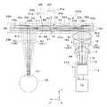
図2を参照して、右側の虚像表示部100Aのうち表示デバイス11Aは、画像光KKを投影光学系12Aに向けて射出する画像形成部である。表示デバイス11Aは、表示用導光部13Aを構成する第1及び第2導光部21,22に共通する単一の画像形成部となっている。表示デバイス(画像形成部)11Aは、不図示の制御装置の制御下で動作する駆動回路19に駆動されて表示動作を行う。表示デバイス11Aは、例えば照明装置11aと光変調パネル11bとを組み合わせたものである。照明装置11aは、RGBの3色に対応した狭帯域の光源と、光源からの3色の照明光をコリメートしたり均一化したりする照明光学系とを有する。3色の光源として、例えばLED、LD等を用いることができる。光変調パネル11bとしては、例えば液晶表示パネルを用いることができる。なお、表示デバイス(画像形成部)11Aは、照明装置11a及び光変調パネル11bで構成されるものに限らず、自発光型の表示パネルとすることもでき、具体的には有機EL表示パネル等を用いることができる。 Referring to FIG. 2,
投影光学系12Aは、表示デバイス(画像形成部)11Aに対応する単一の投射光学系である。投影光学系12Aは、表示デバイス11Aの表示面11dに形成された画像の各点から射出された画像光KKを平行光線とする観点でコリメーターといえる。投影光学系12Aにより、表示デバイス11Aから射出された画像光KKは、表示面11d上の位置に応じた角度情報を持つ平行光線に変換される。見方を変えれば、投影光学系12Aは、表示デバイス11Aの表示面11dに形成された画像を無限遠の虚像に変換する再結像系と捉えることもできる。投影光学系12Aは、複数のレンズ14〜16を含む。これらのレンズ14〜16の光学面は、自由曲面、非球面、球面等のいずれかで構成することができる。 The projection
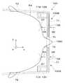
表示用導光部(右眼用導光部)13Aは、投影光学系12Aによって形成された画像光KKを眼EYで観察するための光学系である。表示用導光部13Aは、表示デバイス(画像形成部)11Aから射出される画像光KKの画角のうち、第1画角VA1を担当する画像光K1を導光する第1導光部材である第1導光部21と、第2画角VA2を担当する画像光K2を導光する第2導光部材である第2導光部22とを有する。第1画角VA1は、例えば20°〜45°の範囲に設定され、第2画角VA2も、例えば20°〜45°の範囲に設定され全体で40°〜90°の画角が確保される。図面では、第1導光部21を眼EYのある内側に配置するとともに第2導光部22を外界側に配置しているが、第2導光部22を内側に配置するとともに第1導光部21を外界側に配置することもできる。 The display light guide unit (right eye light guide unit) 13A is an optical system for observing the image light KK formed by the projection
第1導光部(第1導光部材)21と第2導光部(第2導光部材)22とは、平板状であり、不図示の支持体に支持されて互いに平行に配置されている。 The first light guide part (first light guide member) 21 and the second light guide part (second light guide member) 22 have a flat plate shape, are supported by a support body (not shown), and are arranged in parallel to each other. Yes.
第1導光部(第1導光部材)21は、眼EYから見て左半分側の第1画角VA1を受け持っており、平行平板である導光板31aと、画像光K1を導光板31aの内部に取り込むための入射側回折素子31bと、画像光K1を導光板31aの外部に射出するための射出側回折素子31cとをそれぞれ有する。 The first light guide part (first light guide member) 21 takes charge of the first field angle VA1 on the left half side when viewed from the eye EY, and guides the image light K1 from the
これらのうち導光板31aは、ガラス、樹脂材料等の光透過性材料で形成され、第1画角VA1に対応する画像光K1を主にy方向に内部伝搬又は導光させる。導光板31aは、その主面又は表面として、内側面33aと外側面33bとを有し、内側面33aと外側面33bとは、鏡面に加工されている。内側面33aと外側面33bは、互いに平行な導光面として、導光板31a内を伝搬する画像光K1の伝搬角又は反射角を維持する働きを有する。図中に拡大して示すように、導光板31aの表面、つまり内側面33aと外側面33bとには、臨界角以上の全反射角を確保すべく空気層ARが設けられている。 Among these, the
入射側回折素子31bは、投影光学系12A及び導光板31aを経て入射した第1画角VA1の画像光K1を導光板31a内に結合して導光板31a内を伝搬させるものであり、画像光K1を回折してその入射角を所望の回折角に変換する。これにより、導光板31aを通過して入射側回折素子31bで反射された画像光K1は、導光板31a内での全反射条件を満たすようになる。つまり、入射側回折素子31bで回折されて反射された画像光K1の内側面33aへの入射角は、導光板31a内での伝搬の臨界角よりも大きくなっている。入射側回折素子31bは、等価的には傾斜したミラーとして機能し、画像光K1の光路を導光板31a内で伝搬可能な方向に折り曲げる働きを有する。 The incident side
入射側回折素子31bは、反射型の回折素子であり、ホログラム及び表面レリーフ回折格子のいずれか一方である。入射側回折素子31bがホログラムである場合、体積ホログラムとすることが色分離を低減する観点で好ましく、特に体積位相型ホログラムとすること好ましい。入射側回折素子31bが表面レリーフ回折格子である場合、ブレーズド格子とすることが光利用効率の観点で好ましい。ここで、体積ホログラムとは、比較的厚い記録媒体中に格子としてホログラムデータを記録したものであり、特に体積位相型ホログラムは、屈折率格子としてホログラムデータを記録して透過率を高めたものである。表面レリーフ回折格子は、薄膜表面に干渉パターンに対応する凹凸レリーフを形成したものであり、特にブレーズド格子は、断面形状が鋸歯状の凹凸レリーフを形成して回折効率を高めたものである。なお、入射側回折素子31bは、単独で各色の回折を一括して行う回折素子とすることもできるが、各色用の回折素子を積層したものとすることができる。具体的には、例えばR、G、及びBの各色用のホログラムを貼り合わせて入射側回折素子31bとすることもできる。 The incident
射出側回折素子31cは、入射側回折素子31bによって導光板31aに結合されて導光板31a内を伝搬して来た画像光K1を導光板31a外に取り出すものであり、画像光K1を回折してその伝搬角を所望の回折角に変換する。これにより、導光板31a内から射出側回折素子31cに入射した画像光K1は、元の入射側回折素子31bに入射する前の入射角と等しい射出角に復元される。射出側回折素子31cは、等価的には傾斜したミラーとして機能し、導光板31a内を伝搬した画像光K1を内側面33aを介して眼EY側に射出させて、眼EYの前方において表示デバイス11Aの表示面11d上の画像に対応する拡大された虚像を再現又は投影する働きを有する。なお、射出側回折素子31cも、入射側回折素子31bと同様に反射型の回折素子であり、ホログラム及び表面レリーフ回折格子のいずれか一方である。つまり、射出側回折素子31cは、例えば体積位相型ホログラム、ブレーズド格子等で構成することができる。 The exit-side
以上から明らかなように、入射側回折素子31bと射出側回折素子31cとは、互いに対称性を有しており、入射側回折素子31bで発生した色分離を射出側回折素子31cで発生する色分離で補償することになる。これにより、入射側回折素子31bを構成するホログラム又は表面レリーフ回折格子が色分離を生じさせるようなものであっても、全体としての第1導光部21で発生する色分離を低減できる。ここで、色分離とは、各回折素子31b,31cによって発生する色分散であり、波長の差に伴って生じる回折角の差を意味する。 As is clear from the above, the incident-side
第2導光部(第2導光部材)22は、眼EYから見て右半分側の第2画角VA2を受け持っており、平行平板である導光板32aと、画像光K2を導光板32aの内部に取り込むための入射側回折素子32bと、画像光K2を導光板32bの外部に射出するための射出側回折素子32cとをそれぞれ有する。 The second light guide section (second light guide member) 22 is responsible for the second field angle VA2 on the right half side when viewed from the eye EY, and guides the
第2導光部22を構成する導光板32a、入射側回折素子32b、及び射出側回折素子32cは、第1導光部21を構成する導光板31a、入射側回折素子31b、及び射出側回折素子31cと基本的に同様の働きを有するが、第2画角VA2を担当する画像光K2を扱う点で具体的な配置や動作が異なる。 The
導光板32aは、第1導光部21の導光板31aと同様のものであり、ガラス、樹脂材料等の光透過性材料で形成され、画像光K2を主にy方向に内部伝搬させる。導光板31aは、その主面又は表面として、内側面33aと外側面33bとを有し、内側面33aと外側面33bとは、鏡面に加工されている。内側面33aと外側面33bは、互いに平行な導光面として、導光板31a内を伝搬する画像光K2の伝搬角又は反射角を維持する働きを有する。導光板31aの表面、つまり内側面33aと外側面33bとには空気層が設けられている。 The
入射側回折素子32bは、投影光学系12Aを経て入射した第2画角VA2の画像光K2を導光板32a内に結合して導光板32a内を伝搬させるものであり、画像光K2を回折してその入射角を所望の回折角に変換する。これにより、導光板31aを通過して入射側回折素子32bで反射された画像光K2は、導光板31a内での全反射条件を満たすようになる。つまり、入射側回折素子32bで回折されて反射された画像光K2の内側面33aへの入射角は、導光板32aの臨界角よりも大きくなっている。入射側回折素子32bは、等価的には傾斜したミラーとして機能し、画像光K2の光路を導光板32a内で伝搬可能な方向に折り曲げる働きを有する。 The incident side
入射側回折素子32bは、反射型の回折素子であり、ホログラム及び表面レリーフ回折格子のいずれか一方である。つまり、入射側回折素子32bは、例えば体積位相型ホログラム、ブレーズド格子等で構成することができる。 The incident
射出側回折素子32cは、入射側回折素子32bによって導光板32aに結合されて導光板32a内を伝搬して来た画像光K2を導光板32a外に取り出すものであり、画像光K2を回折してその伝搬角を所望の回折角に変換する。これにより、導光板32a内から射出側回折素子32cに入射した画像光K2は、元の入射側回折素子32bに入射する前の入射角と等しい射出角に復元される。射出側回折素子32cは、等価的には傾斜したミラーとして機能し、導光板32a内を伝搬した画像光K2を内側面33aを介して眼EY側に射出させて、眼EYの前方において表示デバイス11Aの表示面11d上の画像に対応する拡大された虚像を再現又は投影する働きを有する。 The exit-side
射出側回折素子32cは、反射型の回折素子であり、ホログラム及び表面レリーフ回折格子のいずれか一方である。つまり、入射側回折素子32bは、例えば体積位相型ホログラム、ブレーズド格子等で構成することができる。 The exit
以上から明らかなように、入射側回折素子32bと射出側回折素子32cとは、互いに対称性を有しており、入射側回折素子32bで発生した色分離を射出側回折素子32cで発生する色分離で補償することになる。これにより、入射側回折素子32bを構成するホログラム又は表面レリーフ回折格子が色分離を生じさせるようなものであっても、全体としての第2導光部22で発生する色分離を低減できる。 As is clear from the above, the incident-side
第2導光部22からの画像光K2は、第1導光部21の導光板31aを通過することになる。このため、特に導光板31aの表面33a,33bのうち画像光K2の通過領域R12については、空気層ではなく、低屈折率層及びAR層のいずれかを形成している。なお、第2導光部22の通過領域R12以外においても、画像光K2に関して全反射条件を満たす限り、低屈折率層AR層等を形成することができる。同様に、第1導光部21の表面33a,33bにおいても、画像光K1に関して全反射条件を満たす限り、低屈折率層AR層等を形成することができる。 The image light K2 from the second
第1導光部21における射出側回折素子31cは、導光板31aを伝搬した画像光K1を平行光として眼EYの瞳PUに集めるように入射させる。この際、表示デバイス11Aの表示面11d上の一方の隅(図面左側の隅)からの主光線は、瞳PUに対して右側前方から入射する。一方、第2導光部22における射出側回折素子32cは、導光板32aを伝搬した画像光K2を平行光として眼EYの瞳PUに集めるように入射させる。この際、表示デバイス11Aの表示面11d上の他方の隅(図面右側の隅)からの主光線は、瞳PUに対して左側前方から入射する。つまり、両射出側回折素子31c,32cからの画像光K1,K2を合成することで、表示面11dに形成された全体画像を左右途切れの無い状態で観察することができるようになる。この際、第1導光部21の入射側回折素子31bと第2導光部22の入射側回折素子32bとが、導光板31aの内側面33aの法線方向から見て分離して隙間が形成されることを防止すれば、画像の欠けや劣化は生じにくくなる。図示の例では、両入射側回折素子31b,32bに互いに重なる共通領域CR1を設けて、眼EYから見た全体の画像光KKによる画像において欠けや劣化が生じることを確実に回避している。この共通領域CR1の詳細については後に詳述する。 The exit-
同上の理由で、第1導光部21の射出側回折素子31cと第2導光部22の射出側回折素子32cとの間にも、互いに重なる共通領域CR2を設けている。これにより、眼EYから見た全体の画像光KKによる画像において欠けや劣化が生じることを確実に回避できる。 For the same reason, a common region CR2 that overlaps is also provided between the exit-
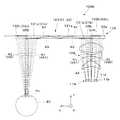
図3を参照して、画像光KKの伝搬角等について説明する。第1導光部21には、半画角を20°として、画角θ10,θ11,θ12に対応する入射角が0°から20°の画像光K1が入射する。ここで、入射角は時計回りを正とし、最大の入射角は、80インチの画面を2.5m先に見ると仮定している。導光板31aの屈折率が約1.64(臨界角約37.6°)であるとして、最大の屈折角ε12は、12°程度になり、中間の屈折角ε11は、6°程度になる。屈折角ε11,ε12は、入射側回折素子31bへの入射角に相当する。最小の画角θ10の画像光K1は、入射側回折素子31bで回折され、反射角又は伝搬角φ10で導光板31a内を伝搬する。同様に、絶対値で最大の画角θ12の画像光K1は、伝搬角φ12で導光板31a内を伝搬し、中間の画角θ11の画像光K1は、伝搬角φ11で導光板31a内を伝搬する。ここで、中間の伝搬角φ11(画像光K1側の画面中心に対応するもの)を例えば55°とすることを目標とする。このため、回折角が図面右側(光軸AX側)の光線から79.5°、61°(δ11)、及び51°であるとすれば、伝搬角φ10,φ11,φ12は、79.5°、55°、及び39°となって、全ての伝搬角φ10〜φ12が、臨界角約37.6°よりも大きくなるとともに80°以下の実用的な範囲となるので、伝搬ロスが無くなる。第2導光部22も同様であり、画角θ20,θ21,θ22に対応する入射角が0°から−20°の画像光K2が入射する。絶対値で最大の屈折角ε22は、−12°程度になり、中間の屈折角ε21は、−6°程度になる。中間の伝搬角φ21(画像光K2側の画面中心に対応するもの)を例えば55°とすることを目標とする。このため、回折角が図面左側(光軸AX側)の光線から40.5°、49°(δ21)、及び59°であるとすれば、伝搬角φ20,φ21,φ22は、40.5°、55°、及び71°となっ、全ての伝搬角φ20〜φ22が、臨界角約37.6°よりも大きくなるとともに80°以下の実用的な範囲となるので、伝搬ロスが無くなる。つまり、第1導光部21と第2導光部22とによって広い画角±20°又は40°をカバーできることが分かる。なお、図示を省略するが、仮に従来型の単一導光部によって半画角±20°を確保しようとした場合、この導光部の導光板内での画像光の反射角又は伝搬角は、一方の画角の端では導光板入射角が臨界角より小さくなり、伝搬ロスが発生し、もう一方の画角の端では、導光板入射角が90度を越えてしまうため、伝搬できなくなる。なお、以上では、理解を簡単にするために具体的な数値を挙げて説明したが、本発明に係る装置は、このような数値に限定されるものではなく、仕様や用途に応じて伝搬の角度条件を設定できる。 With reference to FIG. 3, the propagation angle and the like of the image light KK will be described. The
図2に戻って、表示デバイス11Aと、投影光学系12Aと、第1導光部21の入射側回折素子31bと、第2導光部22の入射側回折素子32bとについては、表裏を反転させて外側に配置することができる。つまり、導光板31a,32aの中間においてyz面に平行に延びる対称面で折り返すように表示デバイス11A及び投影光学系12Aを配置し、入射側回折素子31bを導光板31aの内側面33a上に配置し、入射側回折素子32bを導光板32aの内側面33a上に配置しても、同様の結像が可能になる。 Returning to FIG. 2, the
第1導光部21と第2導光部22とは、一対の保護カバー25a,25bに挟まれて保護されている。保護カバー25a,25bは、光透過性を有する樹脂材料で形成された平行平板であり、表面に反射防止コート等を施すことができる。 The
図1等に戻って、フレーム100Cは、虚像表示部100A,100Bを上部から支持する金属その他の剛体製の本体71と、本体の両端から延びる弾性体製のテンプル部72とを有する。本体71の中央には、一対のノーズパッド74が取り付けられている。 Referring back to FIG. 1 and the like, the
図2を参照して、導光板31a,32a内での画像光K1,K2の光路等について説明する。導光板31a,32a内での画像光K1,K2の反射回数は、導光板31a,32aの厚み等の条件設定により、一致させることも相違させることもできる。例えば両導光板31a,32aの厚みが等しく、光軸AXに沿った光線の入射側回折素子31b,32bによる回折角が等しいとするとともに、光変調パネル11bのy軸に沿った横の各点からの主光線が交わる点を基準として入射側回折素子31b,32bと射出側回折素子31c,32cとが左右対称に配置される場合、画像光K1,K2の反射回数を一致させて入射側回折素子31b,32bからの画像光K1,K2をロス無く射出側回折素子31c,32cに入射させることができる。導光板31a,32a内での画像光K1,K2の反射回数を一致させる場合であっても、入射側回折素子31b,32b等での回折角の調整により、両導光板31a,32aの厚みを互いに異なるものとすることができる。一方、導光板31a,32a内での画像光K1,K2の反射回数を相違させる場合、導光板31a,32aの厚みを互いに適宜に異なるものとし、或いは入射側回折素子31b,32b等での回折角を互いに適宜異なるものとする。この場合、両入射側回折素子31b,32bからの回折光の伝搬角を比較的自由に設定でき、全体での画角を広げやすい。なお、光変調パネル11bの各点からの光束が入射側回折素子32bに形成するスポットのサイズに比較して両導光板31a,32aの厚みを十分薄くすることによって内外面33a,33bで光線の飛びが生じないようにし、導光板31a,32aのどの位置でも画像光K1,K2を取り出せるようにすることもできる。 With reference to FIG. 2, the optical paths of the image lights K1 and K2 in the
なお、導光板31a,32a間又は入射側回折素子31b,32b間の干渉を避ける観点でも、導光板31a,32aの厚みに適宜の差を設けることができ、入射側回折素子31b,32b等での回折角に適宜の差を設けることができる。 From the viewpoint of avoiding interference between the
図4は、図2に示す第1及び第2導光部21,22の変形例である。この場合、導光板31a,32aの外側面33b上に一様な厚みの被覆層131e,132eが形成され、第1導光部21側の被覆層131eに入射側回折素子31bと射出側回折素子31cとが埋め込むように形成され、第2導光部22側の被覆層132eに入射側回折素子32bと射出側回折素子32cとが埋め込むように形成されている。この場合、被覆層131e,132eは、屈折率が均一な媒体であり、被覆層131e,132eの表面は、全反射条件を満たすような平滑面となっている。 FIG. 4 is a modification of the first and second light guides 21 and 22 shown in FIG. In this case,
図5A及び5Bは、第1及び第2導光部21,22の製造方法を説明する図である。図5Aに示すように、第2導光部22となるべき導光板32aを準備し、外側面33bの所定領域にホログラム感光材料82を貼り付け或いは塗布する。その後、内側面33aに垂直な方向から平行光線である物体光L1をホログラム感光材料82に照射しつつ、回折光の方向に対応する方向から平行光線である参照光L2をホログラム感光材料82に照射することで、ホログラム感光材料82中に屈折率パターンが形成される露光が行われ、入射側回折素子32bが完成する。また、図5Bに示すように、第1導光部21となるべき導光板31aを準備し、外側面33bの所定領域にホログラム感光材料81を貼り付け或いは塗布する。その後、内側面33aに垂直な方向から平行光線である物体光L1をホログラム感光材料81に照射しつつ、回折光の方向に対応する方向から平行光線である参照光L2をホログラム感光材料81に照射することで、ホログラム感光材料81中に屈折率パターンが形成される露光が行われ、入射側回折素子31bが完成する。 5A and 5B are diagrams illustrating a method for manufacturing the first and second light guides 21 and 22. As shown in FIG. 5A, a
ホログラム感光材料81,82の露光に際しては、フィルターFL1,FL2等を利用して物体光L1又は参照光L2に照度又は露光強度の分布を持たせることで、入射側回折素子31b,32bの互いに重なる共通領域CR1での影響を相殺する。具体的には、一方の入射側回折素子32bに対応するホログラム感光材料82の露光時には、他方の入射側回折素子31bのエッジE1から一方の入射側回折素子32bのエッジE2にかけての領域で照度又は露光強度を漸減させ、回折効率を同様のパターンで漸減させる。また、他方の入射側回折素子31bに対応するホログラム感光材料81の露光時には、一方の入射側回折素子32bのエッジE2から一方の入射側回折素子31bのエッジE1にかけての領域で照度又は露光強度を漸減させ、回折効率を同様のパターンで漸減させる。結果的に、入射側回折素子31bの回折効率と、入射側回折素子32bの回折効率とを加算した加算値は、共通領域CR1においてフラットであり、共通領域CR1を除いた非共通領域における回折効率を基準として100%の状態となっている。つまり、共通領域CR1での入射側回折素子31b,32bの回折効率の加算値が、非共通領域での単独の入射側回折素子31b,32bの回折効率と等しくなっている。 When the hologram
図6Aは、第1及び第2導光部21,22によって合成された画像の輝度を説明する図である。なお、画像は説明の便宜上輝度パターンがないものとしている。図6Bは、第1及び第2導光部21,22による個々の画像の輝度を説明する図である。この場合、共通領域CR1に対応する画像と非共通領域に対応する画像とが輝度的に滑らかに連続するものとなっている。 FIG. 6A is a diagram for explaining the luminance of the image synthesized by the first and second light guides 21 and 22. It is assumed that the image has no luminance pattern for convenience of explanation. FIG. 6B is a diagram for explaining the brightness of individual images by the first and second light guides 21 and 22. In this case, the image corresponding to the common area CR1 and the image corresponding to the non-common area are smoothly continuous in luminance.
詳細は省略するが、左眼用の表示用導光部13Bを構成する入射側回折素子も、表示用導光部(右眼用導光部)13Aを構成する入射側回折素子31b,32bと同様に作製される。結果的に、表示用導光部(右眼用導光部)13Aと表示用導光部(左眼用導光部)13Bとによって観察者KAに画像光KKが視認される場合の回折効率が略均一になるように回折効率が調整される。 Although details are omitted, the incident-side diffractive element constituting the left-eye display light-guiding
以上は、入射側回折素子31b,32bが共通領域CR1を有する場合の説明であったが、射出側回折素子31c,32cが共通領域CR2を有する場合、例えば入射側回折素子31b,32bに代えて射出側回折素子31c,32c側において、共通領域CR2での射出側回折素子31b,32bの回折効率の加算値が非共通領域での単独の射出側回折素子31c,32cの回折効率と等しくなるようにできる。この場合も、図5A及び5Bに示すと同様の手法を用いることができる。 The above is the description when the incident side diffractive
第1実施形態の虚像表示装置100では、表示用導光部13A,13Bが第1画角VA1を担当して導光する第1導光部21と第2画角VA2を担当して導光する第2導光部22とを有するので、全体の画角を複数の回折素子(複数の入射側回折素子31b,32b、或いは複数の射出側回折素子31c,32c)で分担することになり、全反射条件の確保が容易となって全体としての画角を広くすることができ、或いは、高画角化した場合にも色ムラの発生を抑制することができる。 In the virtual
〔第2実施形態〕
以下、第2実施形態の虚像表示装置ついて説明する。本実施形態に係る虚像表示装置は、第1実施形態の虚像表示装置を変形したものであり、第1実施形態と共通する部分については説明を省略する。[Second Embodiment]
Hereinafter, the virtual image display device of the second embodiment will be described. The virtual image display device according to the present embodiment is a modification of the virtual image display device of the first embodiment, and description of portions common to the first embodiment is omitted.
図7は、第2実施形態の虚像表示装置のうち虚像表示部100Aの光学的な構成を説明する図である。この場合、表示用導光部13Aは、単一の導光部材121によって構成され、単一の導光部材121は、第1実施形態で別体であった第1及び第2導光部21,22を複合して一体化したものである。この単一の導光部材121において、第1導光部21を構成する入射側回折素子31b及び射出側回折素子31cとして一対の透過型回折素子131b,131cが導光板131aの観察者側(−x側)に設けられ、第2導光部22を構成する入射側回折素子32b及び射出側回折素子32cとして一対の反射型回折素子132b,132cが導光板131aの外界側(+x側)に設けられている。 FIG. 7 is a diagram illustrating an optical configuration of the virtual
ここで、入射側回折素子32b又は反射型回折素子132bからの画像光K2が入射側回折素子31bで影響を受けることを防止するため、画像光K2が入射側回折素子31bに入射させないことが望ましい。そのため、入射側回折素子32bによる画像光K2の回折角を相対的に大きくして入射側回折素子31bに入射しないようにしている。 Here, in order to prevent the image light K2 from the incident side
第2実施形態の虚像表示装置によれば、単一の導光部材121を共通化して第1及び第2導光部21,22として用いており、虚像表示装置の光学系を簡素化することができる。 According to the virtual image display device of the second embodiment, the single
〔第3実施形態〕
以下、第3実施形態の虚像表示装置ついて説明する。本実施形態に係る虚像表示装置は、第1実施形態の虚像表示装置を変形したものであり、第1実施形態と共通する部分については説明を省略する。[Third Embodiment]
The virtual image display device according to the third embodiment will be described below. The virtual image display device according to the present embodiment is a modification of the virtual image display device of the first embodiment, and description of portions common to the first embodiment is omitted.
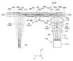
図8は、第3実施形態の虚像表示装置のうち虚像表示部100Aの光学的な構成を説明する図である。この場合、表示デバイス(画像形成部)11Aとしての一対の画像形成部11i,11jと、一対の表示デバイス(画像形成部)11i,11jに対応する一対の投射光学系12i,12jとを備える。図面左側の画像形成部11iからの画像光K1は、投射光学系12iを介して第1導光部21の入射側回折素子31bに入射し、図面右側の画像形成部11jからの画像光K2は、投射光学系12jを介して第2導光部22の入射側回折素子32bに入射する。この場合、画像光K1による画像と、画像光K2による画像との間に重複があり、このように重なる光線部分3a,3bは、互いに平行になっている。これらの光線部分3a,3bは、一対の入射側回折素子31b,32bの共通領域CR1に入射する。この場合、共通領域CR1は離間しているが、同一画像の表示に関わる部分となっており、入射側回折素子31b,32bの共通領域CR1には、同一の入射角の画像光K1,K2が入射する。光線部分3a,3bを平行にすることで、画像光K1による画像と、画像光K2による画像との位置ずれを防止できる。また、この場合、画像形成部11i,11jが独立しているので、共通領域CR1の画像光K1,K2の輝度を個別に調整することができる。つまり、入射側回折素子31b,32b等の回折効率を調整することなく、共通領域CR1に対応する画像と非共通領域に対応する画像とを輝度的に滑らかに連続させて全体で一様に表示することができる。すなわち、入射側回折素子31b,32bの回折効率を均一にした場合に、共通領域CR1を除いた非共通領域の画像光の輝度に対して共通領域CR1の画像光の輝度を表示デバイス(画像形成部)11i,11j側で調整(例えば、50%)することで、最終的に観察者KAの眼EYに入る共通領域CR1の画像光K1,K2の輝度を非共通領域の画像光K1,K2の輝度と合わせることができる。なお、入射側回折素子31b,32bの共通領域CR1の回折効率の調整と、表示デバイス(画像形成部)11i,11jからの画像光の輝度の調整とを組み合わせてもよい。 FIG. 8 is a diagram illustrating an optical configuration of the virtual
図8の例では、重なる光線部分3a,3bが互いに平行になっており、共通領域CR1に略同一の入射角の画像光K1,K2が入射する。しかしながら、共通領域CR1に入射させる画像光K1,K2の入射角には、臨界角その他の伝搬条件を考慮して若干の差を持たせることもできる。実際、全色に対する臨界角が37.6°であるとして緑色の臨界角が40.5°程度である場合、その差分に対応する2,3°だけ緑色の回折角を増減させる設計の自由度が増す。また、緑色以外の他の色(具体的には例えば赤色)であっても、全色に対する臨界角よりも大きいものがあれば、この色については回折角を増減させることができる。つまり、全色に対する臨界角よりも大きい範囲であれば、各色単位で回折角又は伝搬角を調整できるとともに、全色について一括して一様に回折角又は伝搬角を調整することもできる。なお、色ごとに又は全色で回折角を異ならせる入射側回折素子31b,32bは、同時露光するタイプのホログラム素子に限らず、R、G、及びBの各色用のホログラムを貼り合わせる複合タイプのホログラム素子であってもよい。 In the example of FIG. 8, the overlapping
本実施形態の虚像表示装置では、一対の表示デバイス(画像形成部)11i,11jからの画像光K1,K2を一対の投射光学系12i,12jを介して入射側回折素子31b,32bに個々に入射させる。つまり、第1及び第2導光部21,22に対して個別の画像形成部11i,11jからの画像光K1,K2を独立して処理することになる。これにより、画像形成部11i,11jや投射光学系12i,12jの配置の自由度が高まる。 In the virtual image display device of the present embodiment, the image lights K1 and K2 from the pair of display devices (image forming units) 11i and 11j are individually applied to the incident side diffraction
図9は、図8に示す虚像表示装置の変形例を説明する図である。この場合、第2導光部22側において、画像形成部11j及び投射光学系12jが外側に配置されている。 FIG. 9 is a diagram illustrating a modification of the virtual image display device shown in FIG. In this case, the
図10は、図8に示す虚像表示装置の別の変形例を説明する図である。この場合、第1導光部21側の画像形成部11i及び投射光学系12iと、第2導光部22側の画像形成部11j及び投射光学系12jとに共通な光軸AXが導光板31a,32aの傾きを補償するように、導光板31a,32aの内側面33aに対して角度κで傾斜している。 FIG. 10 is a diagram for explaining another modification of the virtual image display device shown in FIG. In this case, the optical axis AX common to the
〔第4実施形態〕
以下、第4実施形態の虚像表示装置ついて説明する。本実施形態に係る虚像表示装置は、第1実施形態の虚像表示装置を変形したものであり、第1実施形態と共通する部分については説明を省略する。[Fourth Embodiment]
The virtual image display device according to the fourth embodiment will be described below. The virtual image display device according to the present embodiment is a modification of the virtual image display device of the first embodiment, and description of portions common to the first embodiment is omitted.
図11は、第4実施形態の虚像表示装置のうち虚像表示部100Aの光学的な構成を説明する図である。この場合、表示デバイス11Aにおいて、一対の光変調パネル11ba,11bbが用いられている。この場合、一対の光変調パネル11ba,11bbが一対の画像形成部となっている。一方の光変調パネル11baからの画像光K1は、単一共通の投影光学系12Aを経て第1導光部21の入射側回折素子31bに入射し、他方の光変調パネル11bbからの画像光K2は、単一で共通の投影光学系12Aを経て第2導光部22の入射側回折素子32bに入射する。 FIG. 11 is a diagram illustrating an optical configuration of the virtual
〔第5実施形態〕
以下、第5実施形態の虚像表示装置ついて説明する。本実施形態に係る虚像表示装置は、第1実施形態の虚像表示装置を変形したものであり、第1実施形態と共通する部分については説明を省略する。[Fifth Embodiment]
The virtual image display device according to the fifth embodiment will be described below. The virtual image display device according to the present embodiment is a modification of the virtual image display device of the first embodiment, and description of portions common to the first embodiment is omitted.
図12は、第5実施形態の虚像表示装置のうち虚像表示部100Aの光学的な構成を説明する図である。この場合、表示用導光部13Aが第1色部材5aと第2色部材5bとを備える。第1色部材5aは、図2等に示す表示用導光部13Aと略同様の構造を有し、第1導光部(第1導光部材)21と第2導光部(第2導光部材)22とを有する。ただし、第1色部材5aは、2色用となっており、例えば緑及び青色の画像に対応する画像光K1a,K2aを第1導光部21と第2導光部22とに分割して導光する。このため、入射側回折素子31b,32bは、緑及び青色の画像光K1a,K2aを所期の回折角の方向に回折しつつ反射する。ここで、画像光K1aは、第1画角VA1に対応し、画像光K2aは、第2画角VA2に対応する。また、射出側回折素子31c,32cも、緑及び青色の画像光K1a,K2aを元の方向に戻すように回折しつつ反射する。第2色部材5bも、図2等に示す表示用導光部13Aと略同様の構造を有し、第1導光部521と第2導光部522とを有する。第2色部材5bは、第1色部材5aとは異なる単色用となっており、例えば赤色の画像に対応する画像光K1b,K2bを第1導光部521と第2導光部522とに分割して導光する。ここで、画像光K1bは、第1画角VA1に対応し、画像光K2bは、第2画角VA2に対応する。入射側回折素子531b,532bは、赤色の画像光K1b,K2bを伝搬のため回折する。また、射出側回折素子531c,532cも、赤色の画像光K1b,K2bを元の方向に戻すように回折する。この虚像表示部100Aでは、緑及び青色の光学系が回折角等の条件で近くなるので、両色を共通の光学系としているが、緑及び青色の光学系をさらに独立させて、表示用導光部13Aを3色用の光学系とすることもできる。 FIG. 12 is a diagram illustrating an optical configuration of the virtual
図13は、図12の虚像表示装置を一部変更したものである。この場合、第2色部材5bが単一の導光部621を有する。つまり、導光部621は、単独で全画角をカバーするものとなっている。導光部621において、入射側回折素子631bは、画像光KKのうち例えば赤及び青色の画像光KKaを所期の回折角の方向に回折しつつ反射し、射出側回折素子631cも、赤及び青色の画像光KKaを元の方向に戻すように回折しつつ反射する。第1色部材5aは、この場合単色用となっており、画像光KKのうち例えば緑色の画像に対応する画像光K1a,K2aを第1導光部(第1導光部材)21と第2導光部(第2導光部材)22とに分割して導光する。 FIG. 13 shows a partial modification of the virtual image display device of FIG. In this case, the
〔その他の変形例等〕
以上実施形態に即して本発明を説明したが、本発明は、上記の実施形態に限られるものではなく、その要旨を逸脱しない範囲において種々の態様において実施することが可能であり、例えば次のような変形も可能である。[Other variations, etc.]
Although the present invention has been described based on the above embodiments, the present invention is not limited to the above embodiments, and can be implemented in various modes without departing from the gist thereof. Such modifications are also possible.
表示デバイス11Aは、光変調パネル11b等を備えるものに限らず、レーザー光源と、レーザー光源からのレーザー光を走査するMEMSその他の走査部とを組み合わせたものとすることができる。 The
第1導光部21の導光板31aの導光領域88における表面33a,33bと、第2導光部22の導光板32aの導光領域88における表面33a,33bとは、屈折率差を利用した全反射によって導光を行うものに限らない。具体的には、例えば図14に示すように、表面33a,33b上に金属や誘電体で形成された薄い反射面89を形成することができる。図示のものに限らず、例えば導光板31aの外側面33bと導光板32aの内側面33aとにのみ、反射膜89を形成することもできる。この際、反射膜89を挟んで両導光板31a,32aを接合することもできる。 The
表示用導光部(右眼用導光部)13Aは、画像光KKを第1及び第2導光部21,22の2つに分割するものに限らず、画像光KKを3つ以上に分割することもできる。 The display light guide unit (right eye light guide unit) 13A is not limited to dividing the image light KK into the first and second
入射側回折素子31b,32bが対象とする画像光K1,K2の波長に差を設けることによっても両画像光K1,K2が影響し合うことを防止できる。例えば図15に示すように、画像光K1の波長と画像光K2の波長との間に視覚的には色の区別が生じないような差があるものとし、第1導光部21の入射側回折素子31bと第2導光部22の入射側回折素子31bとの間で反射効率の波長特性に差を設けておけば、両画像光K1,K2が相互に影響し合うこと又は干渉することを防止できる。具体的には、例えば図12の第5実施形態において、第1色部材5aで導光させる画像光K1a,K2aを赤及び青色とし、第2色部材5bで導光させる画像光K1b,K2bを緑色とした場合、第2色部材5bに入射させる画像光K1b,K2bに若干の波長差を設け、第2色部材5bを構成する入射側回折素子531bの画像光K2bに対する反射効率を画像光K1bに対する反射効率よりも十分低くしつつ、第2色部材5bを構成する入射側回折素子532bの画像光K1bに対する反射効率を画像光K2bに対する反射効率よりも十分低くする。これにより、画像光K1b,K2bが相互に影響して画像が劣化することを防止できる。 It is also possible to prevent the two image lights K1 and K2 from affecting each other by providing a difference in the wavelengths of the image lights K1 and K2 targeted by the incident side diffraction
以上の各実施形態において、画像光KKの各色ごとに回折素子であるホログラム素子による回折角又は導光板内での伝搬角を適宜異なるものに設定することができる。 In each of the above embodiments, the diffraction angle by the hologram element which is a diffraction element or the propagation angle in the light guide plate can be appropriately set different for each color of the image light KK.
以上では、投影光学系12Aによって任意の画素からの画像光KKを構成する各色の光が略同一の角度で第1及び第2導光部21,22に入射することを前提としているが、画像光KKの導光部21,22又は導光板31a,32aへの入射角を各色ごとに異なるものに調整できる。この場合、回折素子である各色のホログラム素子が、例えばRGB同時露光によって作製される場合であっても、各色のホログラム素子からの回折光又は伝搬角を簡易に一致させることができる。また、導光板31a,32aでの各色の臨界角に合わせて回折光又は伝搬角を調整することも可能であり、この場合も、画像光KKの導光部21,22又は導光板31a,32aへの入射角を各色ごとに異なるものに調整することになる。 In the above, it is assumed that light of each color constituting the image light KK from an arbitrary pixel is incident on the first and second light guides 21 and 22 at substantially the same angle by the projection
以上では、第1及び第2導光部21,22によって画像を左右の横方向に分割したが、表示デバイス11Aに対して表示用導光部13Aが上下となって上下に延びるように配置すれば、画像を上下の縦方向に分割して合成することができる。この場合、第1及び第2導光部21,22をx軸の周りに90°回転させると考えることができる。 In the above description, the first and second light guides 21 and 22 divide the image in the left and right lateral directions. However, the display
以上では、シースルー型の虚像表示装置について説明しているが、外界像を観察させる必要がない場合、表示用導光部13Aの外側を遮光体で覆うこともできる。 The see-through type virtual image display device has been described above. However, when it is not necessary to observe an external image, the outside of the display
以上の実施形態において、導光部(導光部材)21,22を構成する導光板31a,32b等を相互に固定する支持体として、例えば導光板31a,32bの±y方向の左右両端を支持するものが考えられる。その際に、各導光板31a,32bの両端に入射した画像光が意図しない角度で元の導光板側に戻る、又は他方の虚像表示部100Bに設けた導光板に画像光が再入射してしまうことが考えられる。図16は、このような迷光を防止するため、導光板31a,32bを両端で固定する支持体86を遮光体とした例を示す。支持体86は、画像光K1,K2を吸収する光吸収体であり、表面に光吸収層を設けたものであってもよい。 In the above embodiment, for example, the left and right ends of the
上記の説明では、実施形態の虚像表示装置100がヘッドマウントディスプレイであるとして具体的な説明を行ったが、虚像表示装置100は、観察者KAが装着する眼鏡型のものに限らず、ヘッドアップディスプレイ(Head-Up Display)に応用することもできる。 In the above description, the virtual
上記の説明では、虚像表示装置100は、右眼及び左眼の双方に対応して、一対の虚像表示部100A,100Bを備えるとしているが、右眼又は左眼のいずれか一方に対してのみ虚像表示部を設け画像を片眼視する構成にしてもよい。 In the above description, the virtual
11A,11B…表示デバイス(画像形成部)、11a…照明装置、11b,11ba,11bb…光変調パネル、12A,12B…投影光学系、12i,12j…投射光学系、13A,13B…表示用導光部、19…駆動回路、21,22…導光部、31a,32a…導光板、31b,32b…入射側回折素子、31c,32c…射出側回折素子、81,82…ホログラム感光材料、100…虚像表示装置、100A,100B…虚像表示部、100C…フレーム、131b,131c…透過型回折素子、132b,132c…反射型回折素子、AX…光軸、CR1,CR2…共通領域、EY…眼、FL1,FL2…フィルター、GK…外界光、KK…画像光、K1,K2…画像光、K1a,K2a,K1b,K2b…画像光、K2a,K2b…画像光、KA…観察者、PU…瞳、VA1…第1画角、VA2…第2画角 11A, 11B ... display device (image forming unit), 11a ... illumination device, 11b, 11ba, 11bb ... light modulation panel, 12A, 12B ... projection optical system, 12i, 12j ... projection optical system, 13A, 13B ... display guide Optical part, 19 ... Drive circuit, 21, 22 ... Light guide part, 31a, 32a ... Light guide plate, 31b, 32b ... Incoming side diffraction element, 31c, 32c ... Emission side diffraction element, 81, 82 ... Hologram photosensitive material, 100 ... Virtual image display device, 100A, 100B ... Virtual image display section, 100C ... Frame, 131b, 131c ... Transmission diffraction element, 132b, 132c ... Reflection diffraction element, AX ... Optical axis, CR1, CR2 ... Common area, EY ... Eye , FL1, FL2 ... filter, GK ... external light, KK ... image light, K1, K2 ... image light, K1a, K2a, K1b, K2b ... image light, K2a, K b ... image light, KA ... observer, PU ... pupil, VA1 ... first angle, VA2 ... second angle
Claims (17)
Translated fromJapanese画像光を前記表示用導光部に向けて射出する画像形成部とを備え、
前記表示用導光部は、前記画像形成部から射出される画像光の画角のうち、第1画角を担当する画像光を導光する第1導光部と、第2画角を担当する画像光を導光する第2導光部とを有し、
前記第1導光部と前記第2導光部とは、画像光を内部に取り込むための入射側回折素子と、画像光を外部に射出するための射出側回折素子とをそれぞれ有する、虚像表示装置。A light guide for display;
An image forming unit for emitting image light toward the display light guide unit,
The display light guide unit is in charge of a first light guide unit that guides image light that is responsible for the first angle of view and a second angle of view among the angle of view of the image light emitted from the image forming unit. A second light guide part for guiding the image light to be
The first light guide unit and the second light guide unit each include an incident side diffractive element for taking image light inside and an emission side diffractive element for emitting image light to the outside, respectively, a virtual image display apparatus.
前記単一の導光部材において、前記第1導光部の前記入射側回折素子及び前記射出側回折素子として透過型回折素子が観察者側に設けられ、前記第2導光部の前記入射側回折素子及び前記射出側回折素子として反射型回折素子が外界側に設けられる、請求項1に記載の虚像表示装置。The display light guide unit is constituted by a single light guide member,
In the single light guide member, a transmission type diffraction element is provided on an observer side as the incident side diffraction element and the emission side diffraction element of the first light guide unit, and the incident side of the second light guide unit is the incident side diffraction element. The virtual image display device according to claim 1, wherein a reflection type diffraction element is provided on the outside side as the diffraction element and the exit side diffraction element.
前記共通領域における一対の回折素子の回折効率の加算値が、非共通領域における単独の回折素子の回折効率と略等しくするように調整される、請求項1〜11のいずれか一項に記載の虚像表示装置。The pair of incident side diffractive elements of the first and second light guide parts or the pair of exit side diffractive elements of the first and second light guide parts have a common region for diffracting common image light,
The added value of the diffraction efficiencies of the pair of diffraction elements in the common region is adjusted to be substantially equal to the diffraction efficiency of a single diffraction element in the non-common region. Virtual image display device.
前記第1及び第2導光部の一対の入射側回折素子、又は前記第1及び第2導光部の一対の射出側回折素子は、共通の画像光を回折する共通領域を有し、
前記画像光形成部において、前記共通領域の画像光の輝度が調整される、請求項1〜11のいずれか一項に記載の虚像表示装置。A pair of image forming units as the image forming unit and a pair of projection optical systems corresponding to the pair of image forming units in order to cause image light to individually enter each of the first and second light guide units. And
The pair of incident side diffractive elements of the first and second light guide parts or the pair of exit side diffractive elements of the first and second light guide parts have a common region for diffracting common image light,
The virtual image display device according to claim 1, wherein the image light forming unit adjusts the luminance of the image light in the common region.
前記左眼用導光部と前記右眼用導光部とによって観察者に画像光が視認される場合の回折効率が略均一になるように回折効率が調整される、請求項12〜14のいずれか一項に記載の虚像表示装置。As the display light guide part, it has a left eye light guide part and a right eye light guide part for guiding image light to the left and right eyes of the observer,
The diffraction efficiency is adjusted so that the diffraction efficiency when image light is visually recognized by an observer is substantially uniform by the left-eye light guide and the right-eye light guide. The virtual image display device according to any one of the above.
前記表示用導光部は、前記画像形成部から射出される画像光の画角のうち、第1画角を担当する画像光を導光する第1導光部と、第2画角を担当する画像光を導光する第2導光部とを有し、
前記第1導光部と前記第2導光部とは、画像光を内部に取り込むための入射側回折素子と、画像光を外部に射出するための射出側回折素子とをそれぞれ有し、
前記第1及び第2導光部の一対の入射側回折素子、又は前記第1及び第2導光部の一対の射出側回折素子は、共通の画像光を回折する共通領域を有し、
前記共通領域における一対の回折素子の回折効率の加算値が、非共通領域における単独の回折素子の回折効率と略等しくするように調整する、虚像表示装置の製造方法。A method for manufacturing a virtual image display device comprising: a display light guide unit; and an image forming unit that emits image light toward the display light guide unit,
The display light guide unit is in charge of a first light guide unit that guides image light that is responsible for the first angle of view and a second angle of view among the angle of view of the image light emitted from the image forming unit. A second light guide part for guiding the image light to be
The first light guide and the second light guide each have an incident side diffractive element for taking image light inside and an emission side diffractive element for emitting image light to the outside,
The pair of incident side diffractive elements of the first and second light guide parts or the pair of exit side diffractive elements of the first and second light guide parts have a common region for diffracting common image light,
A method for manufacturing a virtual image display device, wherein the added value of the diffraction efficiencies of a pair of diffraction elements in the common region is adjusted to be substantially equal to the diffraction efficiency of a single diffraction element in the non-common region.
前記ホログラムの記録に際して、露光強度に勾配を持たせて回折効率を調整する、請求項16に記載の虚像表示装置の製造方法。The incident side diffraction element or the exit side diffraction element is a hologram,
The method for manufacturing a virtual image display device according to claim 16, wherein when recording the hologram, the diffraction efficiency is adjusted by giving a gradient to the exposure intensity.
Priority Applications (3)
| Application Number | Priority Date | Filing Date | Title |
|---|---|---|---|
| JP2016192989AJP2018054978A (en) | 2016-09-30 | 2016-09-30 | Virtual image display device and manufacturing method thereof |
| US15/710,008US10520733B2 (en) | 2016-09-30 | 2017-09-20 | Virtual image display device including first and second light guiding units and manufacturing method thereof |
| US16/660,891US11199712B2 (en) | 2016-09-30 | 2019-10-23 | Virtual image display device including incident side and emission side diffraction elements |
Applications Claiming Priority (1)
| Application Number | Priority Date | Filing Date | Title |
|---|---|---|---|
| JP2016192989AJP2018054978A (en) | 2016-09-30 | 2016-09-30 | Virtual image display device and manufacturing method thereof |
Publications (1)
| Publication Number | Publication Date |
|---|---|
| JP2018054978Atrue JP2018054978A (en) | 2018-04-05 |
Family
ID=61758661
Family Applications (1)
| Application Number | Title | Priority Date | Filing Date |
|---|---|---|---|
| JP2016192989APendingJP2018054978A (en) | 2016-09-30 | 2016-09-30 | Virtual image display device and manufacturing method thereof |
Country Status (2)
| Country | Link |
|---|---|
| US (2) | US10520733B2 (en) |
| JP (1) | JP2018054978A (en) |
Cited By (13)
| Publication number | Priority date | Publication date | Assignee | Title |
|---|---|---|---|---|
| JP2020008749A (en)* | 2018-07-10 | 2020-01-16 | セイコーエプソン株式会社 | Head mounted display |
| WO2020218070A1 (en)* | 2019-04-22 | 2020-10-29 | 株式会社小糸製作所 | Holographic display device |
| JP2020187204A (en)* | 2019-05-13 | 2020-11-19 | セイコーエプソン株式会社 | Display device and display method of image |
| KR20210010537A (en)* | 2018-05-17 | 2021-01-27 | 루머스 리미티드 | Near-eye display with overlapping projector assembly |
| JPWO2019235320A1 (en)* | 2018-06-08 | 2021-06-24 | ソニーグループ株式会社 | Image display device |
| CN113759551A (en)* | 2020-06-03 | 2021-12-07 | 日立乐金光科技株式会社 | Image display device |
| WO2022014952A1 (en)* | 2020-07-17 | 2022-01-20 | 삼성전자 주식회사 | Augmented reality display device |
| JPWO2022163672A1 (en)* | 2021-01-29 | 2022-08-04 | ||
| JP2022160182A (en)* | 2021-04-06 | 2022-10-19 | 株式会社日立エルジーデータストレージ | OPTICAL UNIT AND HEAD MOUNT DISPLAY DEVICE USING THE SAME |
| JP2023050616A (en)* | 2021-09-30 | 2023-04-11 | セイコーエプソン株式会社 | virtual image display |
| US11709361B2 (en) | 2019-07-30 | 2023-07-25 | Seiko Epson Corporation | Optical device and image display apparatus |
| DE112021005822T5 (en) | 2020-11-06 | 2023-08-31 | Sony Group Corporation | IMAGE DISPLAY DEVICE AND IMAGE DISPLAY METHOD |
| EP4502708A4 (en)* | 2022-03-31 | 2025-07-09 | Panasonic Ip Man Co Ltd | OPTICAL SYSTEM AND IMAGE DISPLAY DEVICE |
Families Citing this family (23)
| Publication number | Priority date | Publication date | Assignee | Title |
|---|---|---|---|---|
| US9632226B2 (en) | 2015-02-12 | 2017-04-25 | Digilens Inc. | Waveguide grating device |
| CN113759555B (en) | 2015-10-05 | 2024-09-20 | 迪吉伦斯公司 | Waveguide Display |
| JP6848310B2 (en)* | 2016-09-30 | 2021-03-24 | セイコーエプソン株式会社 | Virtual image display device |
| KR102720048B1 (en)* | 2017-03-22 | 2024-10-18 | 매직 립, 인코포레이티드 | Wearable display device utilizing a composite field of view |
| WO2019238258A1 (en)* | 2018-06-15 | 2019-12-19 | Continental Automotive Gmbh | Device for displaying a virtual image |
| WO2019238259A1 (en)* | 2018-06-15 | 2019-12-19 | Continental Automotive Gmbh | Device for displaying a virtual image |
| JP2020064096A (en)* | 2018-10-15 | 2020-04-23 | ソニー株式会社 | Image display device, head mounted display, manufacturing method of image display device and adjustment method of image display device |
| US10911743B2 (en)* | 2018-10-19 | 2021-02-02 | Facebook Technologies, Llc | Field of view expansion by color separation |
| US20200225471A1 (en) | 2019-01-14 | 2020-07-16 | Digilens Inc. | Holographic Waveguide Display with Light Control Layer |
| US20220283377A1 (en) | 2019-02-15 | 2022-09-08 | Digilens Inc. | Wide Angle Waveguide Display |
| DE102019106020A1 (en)* | 2019-03-08 | 2020-09-10 | Carl Zeiss Ag | Optical system for creating a virtual image and data glasses |
| EP3980825A4 (en)* | 2019-06-07 | 2023-05-03 | Digilens Inc. | WAVEGUIDES WITH TRANSMITTING AND REFLECTING GRIDS AND RELATED MANUFACTURING PROCESSES |
| CA3137994A1 (en) | 2019-06-27 | 2020-12-30 | Lumus Ltd | Apparatus and methods for eye tracking based on eye imaging via a light-guide optical element |
| TWI762947B (en)* | 2019-08-22 | 2022-05-01 | 宏達國際電子股份有限公司 | Display device |
| EP4127820A1 (en)* | 2020-03-23 | 2023-02-08 | InterDigital CE Patent Holdings, SAS | Waveguide display system with wide field of view |
| JP2022039127A (en)* | 2020-08-28 | 2022-03-10 | 株式会社日立エルジーデータストレージ | Head-mounted display |
| CN114153067A (en)* | 2020-09-07 | 2022-03-08 | 华为技术有限公司 | A near-eye display device |
| US11531202B2 (en)* | 2020-11-05 | 2022-12-20 | Microsoft Technology Licensing, Llc | Waveguide assembly with virtual image focus |
| WO2022150841A1 (en) | 2021-01-07 | 2022-07-14 | Digilens Inc. | Grating structures for color waveguides |
| WO2022185609A1 (en)* | 2021-03-05 | 2022-09-09 | パナソニックIpマネジメント株式会社 | Optical system and image display device |
| KR102676604B1 (en) | 2021-07-04 | 2024-06-18 | 루머스 리미티드 | Display with stacked light guiding elements providing different parts of the field of view |
| US11727891B2 (en)* | 2021-11-16 | 2023-08-15 | Meta Platforms Technologies, Llc | Integrated electronic and photonic backplane architecture for display panels |
| US12416808B2 (en)* | 2023-04-24 | 2025-09-16 | Microsoft Technology Licensing, Llc | Waveguide combiner with separate in-coupling and out-coupling plates |
Family Cites Families (6)
| Publication number | Priority date | Publication date | Assignee | Title |
|---|---|---|---|---|
| US7573640B2 (en)* | 2005-04-04 | 2009-08-11 | Mirage Innovations Ltd. | Multi-plane optical apparatus |
| JP5151518B2 (en) | 2008-02-07 | 2013-02-27 | ソニー株式会社 | Optical device and image display device |
| JP2012098324A (en) | 2010-10-29 | 2012-05-24 | Seiko Epson Corp | Light guide plate and virtual image display device having the same |
| US8903207B1 (en)* | 2011-09-30 | 2014-12-02 | Rockwell Collins, Inc. | System for and method of extending vertical field of view in head up display utilizing a waveguide combiner |
| DE102015122055B4 (en)* | 2015-12-17 | 2018-08-30 | Carl Zeiss Ag | Optical system and method for transmitting a source image |
| DE102016201567A1 (en)* | 2016-02-02 | 2017-08-03 | Robert Bosch Gmbh | Projection device for a data glasses, method for displaying image information by means of a projection device and control device |
- 2016
- 2016-09-30JPJP2016192989Apatent/JP2018054978A/enactivePending
- 2017
- 2017-09-20USUS15/710,008patent/US10520733B2/enactiveActive
- 2019
- 2019-10-23USUS16/660,891patent/US11199712B2/enactiveActive
Cited By (27)
| Publication number | Priority date | Publication date | Assignee | Title |
|---|---|---|---|---|
| KR102750567B1 (en)* | 2018-05-17 | 2025-01-06 | 루머스 리미티드 | Near-Eye Display with Overlapping Projector Assembly |
| JP2024069241A (en)* | 2018-05-17 | 2024-05-21 | ルムス エルティーディー. | Near-eye display with overlapping projector assemblies - Patents.com |
| IL278511B1 (en)* | 2018-05-17 | 2024-09-01 | Lumus Ltd | A near-eye display containing overlapping projector assemblies |
| KR20210010537A (en)* | 2018-05-17 | 2021-01-27 | 루머스 리미티드 | Near-eye display with overlapping projector assembly |
| JP7446620B2 (en) | 2018-05-17 | 2024-03-11 | ルムス エルティーディー. | Near eye display with overlapping projector assemblies |
| JP2021524053A (en)* | 2018-05-17 | 2021-09-09 | ルムス エルティーディー. | Near-eye display with overlapping projector assemblies |
| IL278511B2 (en)* | 2018-05-17 | 2025-01-01 | Lumus Ltd | Near-eye display having overlapping projector assemblies |
| JP7720650B2 (en) | 2018-05-17 | 2025-08-08 | ルムス エルティーディー. | Near-eye display with overlapping projector assemblies |
| JPWO2019235320A1 (en)* | 2018-06-08 | 2021-06-24 | ソニーグループ株式会社 | Image display device |
| US12025810B2 (en) | 2018-06-08 | 2024-07-02 | Sony Corporation | Image display apparatus |
| JP2020008749A (en)* | 2018-07-10 | 2020-01-16 | セイコーエプソン株式会社 | Head mounted display |
| JP7131145B2 (en) | 2018-07-10 | 2022-09-06 | セイコーエプソン株式会社 | head mounted display |
| WO2020218070A1 (en)* | 2019-04-22 | 2020-10-29 | 株式会社小糸製作所 | Holographic display device |
| JP2020187204A (en)* | 2019-05-13 | 2020-11-19 | セイコーエプソン株式会社 | Display device and display method of image |
| JP7275829B2 (en) | 2019-05-13 | 2023-05-18 | セイコーエプソン株式会社 | Display device and image display method |
| US11709361B2 (en) | 2019-07-30 | 2023-07-25 | Seiko Epson Corporation | Optical device and image display apparatus |
| CN113759551A (en)* | 2020-06-03 | 2021-12-07 | 日立乐金光科技株式会社 | Image display device |
| JP2021189379A (en)* | 2020-06-03 | 2021-12-13 | 株式会社日立エルジーデータストレージ | Video display device |
| US12078809B2 (en) | 2020-07-17 | 2024-09-03 | Samsung Electronics Co., Ltd. | Augmented reality display device |
| WO2022014952A1 (en)* | 2020-07-17 | 2022-01-20 | 삼성전자 주식회사 | Augmented reality display device |
| DE112021005822T5 (en) | 2020-11-06 | 2023-08-31 | Sony Group Corporation | IMAGE DISPLAY DEVICE AND IMAGE DISPLAY METHOD |
| WO2022163672A1 (en)* | 2021-01-29 | 2022-08-04 | 富士フイルム株式会社 | Image display device |
| JP7583070B2 (en) | 2021-01-29 | 2024-11-13 | 富士フイルム株式会社 | Image display device |
| JPWO2022163672A1 (en)* | 2021-01-29 | 2022-08-04 | ||
| JP2022160182A (en)* | 2021-04-06 | 2022-10-19 | 株式会社日立エルジーデータストレージ | OPTICAL UNIT AND HEAD MOUNT DISPLAY DEVICE USING THE SAME |
| JP2023050616A (en)* | 2021-09-30 | 2023-04-11 | セイコーエプソン株式会社 | virtual image display |
| EP4502708A4 (en)* | 2022-03-31 | 2025-07-09 | Panasonic Ip Man Co Ltd | OPTICAL SYSTEM AND IMAGE DISPLAY DEVICE |
Also Published As
| Publication number | Publication date |
|---|---|
| US20200049999A1 (en) | 2020-02-13 |
| US11199712B2 (en) | 2021-12-14 |
| US10520733B2 (en) | 2019-12-31 |
| US20180095283A1 (en) | 2018-04-05 |
Similar Documents
| Publication | Publication Date | Title |
|---|---|---|
| US11199712B2 (en) | Virtual image display device including incident side and emission side diffraction elements | |
| JP6232863B2 (en) | Optical device and image display apparatus | |
| AU2018239357B2 (en) | Method and system for waveguide projector with wide field of view | |
| CN102213830B (en) | Head-mounted display device | |
| JP6992251B2 (en) | Video display device and light guide device | |
| US8576491B2 (en) | Virtual image display device | |
| EP2639623B1 (en) | Image display device and image generating device | |
| KR102097845B1 (en) | Image display device, image generating device, and transparent spatial light modulating device | |
| CN106802487B (en) | Beam diameter amplifying element and display device | |
| US9164221B2 (en) | Light beam expanding device, image display device, and optical device | |
| JP5633406B2 (en) | Virtual image display device | |
| US8638499B2 (en) | Image display apparatus | |
| JP6225474B2 (en) | Display device | |
| EP3518024A1 (en) | Display device | |
| JP2022553595A (en) | Display waveguides with high refractive index sections | |
| WO2005088384A1 (en) | Image display optical system and image display apparatus | |
| US11067810B2 (en) | Head-mounted display apparatus | |
| JP2006003872A (en) | Optical element, combiner optical system, and information display device | |
| US20210063752A1 (en) | Virtual image display apparatus and light-guiding device | |
| US11467417B2 (en) | Display device | |
| JP6848310B2 (en) | Virtual image display device | |
| US11269189B2 (en) | Image display device | |
| US20210063750A1 (en) | Head-mounted display | |
| US20250102809A1 (en) | Display device | |
| JP5754154B2 (en) | Virtual image display device |
Legal Events
| Date | Code | Title | Description |
|---|---|---|---|
| RD05 | Notification of revocation of power of attorney | Free format text:JAPANESE INTERMEDIATE CODE: A7425 Effective date:20190322 | |
| RD03 | Notification of appointment of power of attorney | Free format text:JAPANESE INTERMEDIATE CODE: A7423 Effective date:20190402 |