JP2018054580A - Detection apparatus, detection method, and detection program - Google Patents
Detection apparatus, detection method, and detection programDownload PDFInfo
- Publication number
- JP2018054580A JP2018054580AJP2016194581AJP2016194581AJP2018054580AJP 2018054580 AJP2018054580 AJP 2018054580AJP 2016194581 AJP2016194581 AJP 2016194581AJP 2016194581 AJP2016194581 AJP 2016194581AJP 2018054580 AJP2018054580 AJP 2018054580A
- Authority
- JP
- Japan
- Prior art keywords
- frequency
- component
- wave
- abnormality
- extracted
- Prior art date
- Legal status (The legal status is an assumption and is not a legal conclusion. Google has not performed a legal analysis and makes no representation as to the accuracy of the status listed.)
- Pending
Links
Images


Landscapes
- Measurement Of Velocity Or Position Using Acoustic Or Ultrasonic Waves (AREA)
Abstract
Translated fromJapaneseDescription
Translated fromJapanese本発明は、障害物を検出する検出装置、検出方法、および検出プログラムに関する。 The present invention relates to a detection device, a detection method, and a detection program for detecting an obstacle.
従来、自動車等の車両に取り付けられた超音波センサ(ソナー)を用いて車両の周辺に存在する障害物を検出する障害物検出装置が知られている(例えば、特許文献1参照)。超音波センサは、車両の周辺に向けて超音波(送信波)を送信し、障害物検出装置は、その超音波が障害物に当たって反射した反射波を受信し、その反射波に基づいて障害物を検出する。 2. Description of the Related Art Conventionally, an obstacle detection device that detects an obstacle existing around a vehicle using an ultrasonic sensor (sonar) attached to a vehicle such as an automobile is known (for example, see Patent Document 1). The ultrasonic sensor transmits an ultrasonic wave (transmission wave) toward the periphery of the vehicle, and the obstacle detection device receives a reflected wave reflected by the ultrasonic wave hitting the obstacle, and the obstacle is based on the reflected wave. Is detected.
上述した障害物検出装置では、例えば障害物の検出処理を行う回路または超音波センサの故障などの異常が生じることがあるため、その異常を検出できる技術が望まれる。さらには、コストを抑えることも望まれる。 In the obstacle detection device described above, for example, an abnormality such as a failure of a circuit for performing an obstacle detection process or an ultrasonic sensor may occur. Therefore, a technique capable of detecting the abnormality is desired. Furthermore, it is also desired to reduce costs.
本発明の目的は、コストをかけずに異常を検出できる検出装置、検出方法、および検出プログラムを提供することである。 An object of the present invention is to provide a detection device, a detection method, and a detection program that can detect an abnormality without incurring costs.
本発明に係る検出装置は、車両において用いられる超音波センサから、第1の周波数の第1の送信波を送信させた後、前記超音波センサが前記第1の送信波の反射波を受信する前に前記第1の周波数と異なる第2の周波数の第2の送信波を送信させる送信部と、前記超音波センサにより受信された反射波のうち受信レベルが所定閾値より大きい反射波から、周波数の成分を抽出する抽出部と、前記成分の抽出結果に基づいて、障害物の有無および異常の有無を判定する検出部と、を備える。 In the detection apparatus according to the present invention, after transmitting a first transmission wave having a first frequency from an ultrasonic sensor used in a vehicle, the ultrasonic sensor receives a reflected wave of the first transmission wave. From a transmission unit that transmits a second transmission wave having a second frequency different from the first frequency before, and a reflected wave having a reception level greater than a predetermined threshold among the reflected waves received by the ultrasonic sensor, the frequency An extraction unit for extracting the components of the above and a detection unit for determining the presence / absence of an obstacle and the presence / absence of an abnormality based on the extraction result of the components.
本発明に係る検出方法は、車両において用いられる超音波センサから、第1の周波数の第1の送信波を送信させた後、前記超音波センサが前記第1の送信波の反射波を受信する前に前記第1の周波数と異なる第2の周波数の第2の送信波を送信させるステップと、前記超音波センサにより受信された反射波のうち受信レベルが所定閾値より大きい反射波から、周波数の成分を抽出するステップと、前記成分の抽出結果に基づいて、障害物の有無および異常の有無を判定するステップと、を含む。 In the detection method according to the present invention, after transmitting a first transmission wave having a first frequency from an ultrasonic sensor used in a vehicle, the ultrasonic sensor receives a reflected wave of the first transmission wave. A step of transmitting a second transmission wave having a second frequency different from the first frequency, and a reflected wave having a reception level greater than a predetermined threshold among the reflected waves received by the ultrasonic sensor; Extracting a component, and determining the presence or absence of an obstacle and the presence or absence of an abnormality based on the extraction result of the component.
本発明に係る検出プログラムは、車両において用いられる超音波センサから、第1の周波数の第1の送信波を送信させた後、前記超音波センサが前記第1の送信波の反射波を受信する前に前記第1の周波数と異なる第2の周波数の第2の送信波を送信させる処理と、前記超音波センサにより受信された反射波のうち受信レベルが所定閾値より大きい反射波から、周波数の成分を抽出する処理と、前記成分の抽出結果に基づいて、障害物の有無および異常の有無を判定する処理と、をコンピュータに実行させる。 In the detection program according to the present invention, after transmitting a first transmission wave having a first frequency from an ultrasonic sensor used in a vehicle, the ultrasonic sensor receives a reflected wave of the first transmission wave. A process of transmitting a second transmission wave having a second frequency different from the first frequency before and a reflected wave having a reception level greater than a predetermined threshold among the reflected waves received by the ultrasonic sensor. A computer is caused to execute a process of extracting a component and a process of determining the presence / absence of an obstacle and the presence / absence of an abnormality based on the extraction result of the component.
本発明によれば、コストをかけずに異常を検出できる。 According to the present invention, an abnormality can be detected without cost.
以下、本発明の実施の形態について、図面を参照して説明する。 Embodiments of the present invention will be described below with reference to the drawings.
まず、本発明の実施の形態に係る検出装置100の構成について、図1を用いて説明する。図1は、本実施の形態の検出装置100の構成例を示す図である。 First, the configuration of the
図1に示す検出装置100は、自動車等の車両(図2参照)に搭載され、同じ車両に搭載された超音波センサ2と電気的に接続される。超音波センサ2は、例えば、図2に示すように、車両1の後方部(例えば、リヤダンパ近傍)に取り付けられる。なお、本実施の形態では、検出装置100および超音波センサ2を車両1に搭載する場合を例に挙げて説明するが、検出装置100および超音波センサ2は、車両(自動車)以外の移動体に搭載されてもよい。 A
超音波センサ2は、超音波(以下、送信波という)を車両1の後方に向けて送信する。本実施の形態では、超音波センサ2は、まず第1の送信波を送信し、その後、超音波センサ2が第1の送信波の反射波を受信する前に第2の送信波を送信する。第1の送信波の周波数と第2の送信波の周波数とは異なる。 The
ここで、第1の送信波と第2の送信波について説明する。 Here, the first transmission wave and the second transmission wave will be described.
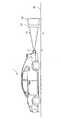
図2は、第1の送信波と第2の送信波それぞれの到達範囲を示す概念図である。図2において、到達範囲S1は第1の送信波の到達範囲を示し、到達範囲S2は第2の送信波の到達範囲を示す。図2に示すように、到達範囲S1と到達範囲S2は、ほぼ同一である(同一であってもよい)。すなわち、第1の送信波の振幅レベル(送信レベル)と第2の送信波の振幅レベル(送信レベル)は、同一またはほぼ同一である。また、図2において、領域41は、到達範囲S1、S2に対応する路面40の領域である。 FIG. 2 is a conceptual diagram showing the reach ranges of the first transmission wave and the second transmission wave. In FIG. 2, the reachable range S1 indicates the reachable range of the first transmission wave, and the reachable range S2 indicates the reachable range of the second transmit wave. As shown in FIG. 2, the reach range S1 and the reach range S2 are substantially the same (may be the same). That is, the amplitude level (transmission level) of the first transmission wave and the amplitude level (transmission level) of the second transmission wave are the same or substantially the same. Moreover, in FIG. 2, the area |
図2に示すように、路面40の領域41上に障害物50が存在する場合、超音波センサ2から送信された第1の送信波と第2の送信波は、障害物50に当たって反射する。障害物50は、例えば、壁、縁石等の物体、または、人間、動物等の生物などである。 As shown in FIG. 2, when the
超音波センサ2は、障害物50に当たって反射された超音波(以下、反射波という)を受信する。この反射波は、第1の送信波に対する反射波と、第2の送信波に対する反射波とを含む混合波である。 The
なお、ここででは、超音波センサ2を車両1の後方部に搭載し、車両1の後方に向けて送信波を送信する場合を例に挙げて説明するが、これに限定されない。超音波センサ2は、例えば、車両1の側方または前方に搭載され、車両1の側方または前方に向けて送信波を送信してもよい。 Here, a case where the
以上、第1の送信波と第2の送信波について説明した。以下、図1の説明に戻る。 The first transmission wave and the second transmission wave have been described above. Returning to the description of FIG.
図1に示すように、検出装置100は、制御部10、送信回路20、および受信回路30を備える。検出装置100は、例えば、超音波距離測定ECU(Electronic Control Unit)である。 As illustrated in FIG. 1, the
送信回路20は、例えば、発振回路(図示略)と駆動回路(図示略)を含んで構成される。発振回路は、所定周波数の矩形波を生成する。駆動回路は、生成された矩形波を駆動信号として超音波センサ2へ出力する。これにより、超音波センサ2は、予め設定された送波電圧ゲイン(送信ゲインともいう)で第1の送信波と第2の送信波を送信する。 The
受信回路30は、増幅回路(図示略)とフィルタ回路(図示略)を含んで構成される。増幅回路は、超音波センサ2から受け取った反射波(受信信号)を、予め設定された受波信号ゲイン(受信ゲインともいう)で増幅する。フィルタ回路は、増幅された受信信号に対してフィルタリングを行い、その受信信号を制御部10へ出力する。 The
制御部10は、送受信制御部11、抽出部12、および検出部13を有する。図示は省略するが、制御部10は、例えば、CPU(Central Processing Unit)、制御プログラムを格納したROM(Read Only Memory)等の記憶媒体、RAM(Random Access Memory)等の作業用メモリ、および通信回路を有する。図1に示した送受信制御部11、抽出部12、および検出部13の機能(詳細は後述)は、CPUが制御プログラムを実行することにより実現される。 The
送受信制御部11(送信部の一例)は、超音波センサ2から第1の送信波を送信した後第2の送信波を送信するように送信回路20を制御する。また、例えば、送受信制御部11は、送信回路20および受信回路30のそれぞれに対し、制御信号を出力する。送信回路20へ出力される制御信号には、例えば、送波電圧ゲインの指示が含まれる。また、受信回路30へ出力される制御信号には、例えば、受波信号ゲインの指示が含まれる。 The transmission / reception control unit 11 (an example of a transmission unit) controls the
抽出部12は、受信回路30から受け取った受信信号に対してフーリエ変換等を行い、周波数成分を抽出する。抽出部12より抽出される周波数成分を、以下、周波数成分A、周波数成分Bという。なお、周波数成分とは、周波数、周波数の成分の強さ、周波数の振幅等を意味する。 The
周波数成分Aとは、第1の送信波の周波数と同じ周波数、または、車両1の走行によりドップラー効果が生じる場合の周波数のずれを考慮して設定された第1の範囲内の周波数のいずれかを有する成分である。 The frequency component A is either the same frequency as the frequency of the first transmission wave, or a frequency within the first range set in consideration of a frequency shift when the Doppler effect is caused by traveling of the
周波数成分Bとは、第2の送信波の周波数と同じ周波数、または、車両1の走行によりドップラー効果が生じる場合の周波数のずれを考慮して設定された第2の範囲(第1の範囲とは異なる)内の周波数のいずれかを有する成分である。 The frequency component B is the same frequency as the frequency of the second transmission wave, or a second range set in consideration of a frequency shift when the Doppler effect is caused by traveling of the vehicle 1 (the first range and Are components having any of the frequencies within.
ここで、第1の送信波の周波数と、第2の送信波の周波数とは、たとえ車両の走行によりドップラー効果が生じたとしても、周波数成分A、Bの周波数が重ならないように設定されることが望ましい。なお、送信波の周波数は、固定周波数でなく、周波数に帯域幅を持たせ、徐々に周波数を変化させる送信波などでもよい。 Here, the frequency of the first transmission wave and the frequency of the second transmission wave are set so that the frequencies of the frequency components A and B do not overlap even if the Doppler effect occurs due to the running of the vehicle. It is desirable. Note that the frequency of the transmission wave is not a fixed frequency, but may be a transmission wave that has a bandwidth and gradually changes the frequency.
よって、本実施の形態では、抽出部12は、周波数が第1の送信波の周波数と同じである周波数成分、または、周波数が第1の範囲内である周波数成分(いずれも上述した周波数成分Aに相当)を抽出する。同様に、抽出部12は、周波数が第2の送信波の周波数と同じである周波数成分、または、周波数が第2の範囲内である周波数成分(いずれも上述した周波数成分Bに相当)を抽出する。 Therefore, in the present embodiment, the
なお、路面40の領域41上に障害物50が存在しない場合、反射波(受信信号)は受信されないため、抽出部12は、周波数成分A、Bのいずれも抽出しない。 In addition, when the
なお、本実施の形態では、抽出部12は、受信レベルが所定閾値より大きい反射波を周波数成分の抽出処理の対象とし、受信レベルが所定閾値(ゼロでもよい)以下の反射波については周波数成分の抽出処理の対象としない。また、微小レベルも含むすべての反射波の周波数成分の抽出処理をし、抽出成分の信号の強さから判定してもよい。 In the present embodiment, the
本実施の形態では、第1の送信波の振幅レベル(送信レベル)は、第1の送信波に対する路面40からの反射波の受信レベルが所定閾値以下となるように設定されている。同様に、第2の送信波の振幅レベル(送信レベル)は、第2の送信波に対する路面40からの反射波の受信レベルが所定閾値以下となるように設定されている。 In the present embodiment, the amplitude level (transmission level) of the first transmission wave is set such that the reception level of the reflected wave from the
検出部13は、周波数成分の抽出結果に基づいて、障害物の有無および異常の有無を判定する。異常は、例えば、検出装置100(制御部10、送信回路20、または受信回路30)の故障、超音波センサ2の故障または劣化、超音波センサ2の送受信面における異物の付着、車両周辺の環境の問題(例えば、ノイズの受信、または、他の車両から送信される送信波の受信、悪天候等)などである。 The
例えば、周波数成分Aと周波数成分Bの両方が抽出された場合、検出部13は、図2に示した領域41上に障害物50があると判定し、かつ、異常がないと判定する。また、検出部13は、送信波の速度と、送信波を送信してから反射波を受信するまでの時間とに基づいて、超音波センサ2と障害物50との間の距離を算出する。 For example, when both the frequency component A and the frequency component B are extracted, the
そして、検出部13は、障害物50がある旨を示す検出結果情報を所定装置へ出力する。この検出結果情報には、異常がない旨を示す情報、および、超音波センサ2と障害物50との間の距離を示す情報の少なくとも一方が含まれてもよい。 Then, the
検出結果情報の出力先となる所定装置は、例えば、超音波距離測定ECU以外のECU(例えば、車両の運転支援を行うECUなど)、または、ディスプレイ装置などであってもよい。 The predetermined device that is the output destination of the detection result information may be, for example, an ECU other than the ultrasonic distance measurement ECU (for example, an ECU that supports driving of the vehicle), a display device, or the like.
また、例えば、障害物が存在せず、反射波が受信されないことで、周波数成分Aと周波数成分Bのいずれも抽出されなかった場合、検出部13は、図2に示した領域41上に障害物50がないと判定し、かつ、異常がないと判定する。 Further, for example, when no obstacle is present and no reflected wave is received, and neither the frequency component A nor the frequency component B is extracted, the
そして、検出部13は、障害物50がない旨を示す検出結果情報を所定装置へ出力する。この検出結果情報には、異常がない旨を示す情報が含まれてもよい。 Then, the
また、例えば、周波数成分Aのみが抽出された場合、または、周波数成分Bのみが抽出された場合、検出部13は、障害物50の検出が不可能であると判定し、かつ、異常があると判定する。 For example, when only the frequency component A is extracted, or when only the frequency component B is extracted, the
そして、検出部13は、異常がある旨を示す検出結果情報を所定装置へ出力する。 And the
以上、検出装置100の構成について説明した。 The configuration of the
次に、検出装置100の動作について、図3を用いて説明する。図3は、検出装置100の動作例を示すフローチャートである。 Next, operation | movement of the
まず、送信回路20は、第1の送信波と第2の送信波を送信するように超音波センサ2を制御する(ステップS101)。これにより、超音波センサ2は、車両1の後方に向けて第1の送信波と第2の送信波を連続で送信する。これにより、図2に示したように、第1の送信波は到達範囲S1に到達し、第2の送信波は到達範囲S2に到達する。 First, the
次に、受信回路30は、超音波センサ2から受け取った反射波(受信信号)を増幅し、フィルタリングを行う(ステップS102)。その後、受信回路30は、受信信号を制御部10へ出力する。 Next, the
次に、制御部10の抽出部12は、受信信号に対してフーリエ変換等を行い、周波数成分を抽出する(ステップS103)。 Next, the
次に、制御部10の検出部13は、周波数成分の抽出結果に基づいて、障害物の有無および異常の有無を判定する(ステップS104)。 Next, the
次に、検出部13は、判定結果に応じた検出結果情報を所定装置へ出力する(ステップS105)。 Next, the
以上、検出装置100の動作について説明した。 The operation of the
詳述してきたように、本実施の形態の検出装置100は、周波数が異なる第1の送信波と第2の送信波を連続で超音波センサ2に送信させ、反射波から周波数成分を抽出し、周波数成分の抽出結果に基づいて、障害物の有無および異常の有無を判定する。よって、検出装置100は、コストをかけずに異常を検出できる。 As described in detail, the
本発明は、上記実施の形態の説明に限定されず、種々の変形が可能である。以下、各変形例について説明する。 The present invention is not limited to the description of the above embodiment, and various modifications can be made. Hereinafter, each modification will be described.
<変形例1>
上記実施の形態では、図2に示したように、第1の送信波の到達範囲S1と第2の送信波の到達範囲S2がほぼ同じである場合を例に挙げて説明したが、到達範囲S1と到達範囲S2とは大きく異なってもよい。この具体例について、図4を用いて以下に説明する。<
In the above embodiment, as illustrated in FIG. 2, the case where the first transmission wave arrival range S1 and the second transmission wave arrival range S2 are substantially the same has been described as an example. S1 and reachable range S2 may differ greatly. A specific example of this will be described below with reference to FIG.
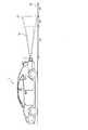
図4は、本変形例に係る到達範囲S1、S2を示す概念図である。図4に示すように、到達範囲S2は到達範囲S1より広い。すなわち、送信波T2の振幅レベル(送信レベル)は、送信波T1の振幅レベル(送信レベル)よりも大きい。この場合、第2の送信波は、第1の送信波よりも遠方に到達する。 FIG. 4 is a conceptual diagram showing the reach ranges S1 and S2 according to this modification. As shown in FIG. 4, the reachable range S2 is wider than the reachable range S1. That is, the amplitude level (transmission level) of the transmission wave T2 is larger than the amplitude level (transmission level) of the transmission wave T1. In this case, the second transmission wave reaches farther than the first transmission wave.
図4において、領域42は、到達範囲S1に対応する路面40の領域である。領域43は、到達範囲S1外かつ到達範囲S2内に対応する路面40の領域である。領域44は、到達範囲S2外の範囲に対応する路面40の領域である。 In FIG. 4, a
なお、以下では、領域42に対応する領域42の上方の空間を「領域42上の空間」という。また、領域43に対応する領域43の上方の空間を「領域43上の空間」という。また、領域44に対応する領域44の上方の空間を「領域44上の空間」という。 Hereinafter, the space above the
以下、本変形例に係る検出部13の処理について説明する。 Hereinafter, the process of the
まず、検出部13は、送信波の速度と、送信波を送信してから反射波を受信するまでの時間とに基づいて、受信された反射波が、領域42上の空間、領域43上の空間、領域44上の空間のうちのどの空間から来た反射波であるかを判定する。 First, based on the speed of the transmission wave and the time from transmission of the transmission wave to reception of the reflected wave, the
受信された反射波が領域42上の空間から来た反射波である場合、検出部13は、上記実施の形態で説明した障害物の有無および異常の有無の判定を行い、判定結果に応じた検出結果情報を所定装置へ出力する。 When the received reflected wave is a reflected wave coming from the space on the
受信された反射波が領域43上の空間から来た反射波である場合、例えば、検出部13は、まず、周波数成分Aが抽出されたか否かを判定する。 When the received reflected wave is a reflected wave coming from the space on the
周波数成分Aが抽出された場合、検出部13は、障害物の検出が不可能であると判定し、かつ、異常があると判定し、その旨を示す検出結果情報を所定装置へ出力する。 When the frequency component A is extracted, the
一方、周波数成分Aが抽出されなかった場合、検出部13は、異常がないと判定し、続いて、周波数成分Bが抽出されたか否かを判定する。 On the other hand, when the frequency component A is not extracted, the
周波数成分Bが抽出された場合、検出部13は、領域43に障害物があると判定する。そして、検出部13は、障害物がある旨を示す検出結果情報を所定装置へ出力する。なお、この検出結果情報には、超音波センサ2から障害物までの距離を示す情報、および、異常がない旨を示す情報の少なくとも一方が含まれてもよい。 When the frequency component B is extracted, the
一方、周波数成分Bが抽出されなかった場合、検出部13は、領域43に障害物がないと判定する。そして、検出部13は、障害物がない旨を示す検出結果情報を所定装置へ出力する。なお、この検出結果情報には、異常がない旨を示す情報が含まれてもよい。 On the other hand, when the frequency component B is not extracted, the
受信された反射波が領域44上の空間から来た反射波である場合、例えば、検出部13は、周波数成分Aおよび周波数成分Bの少なくとも一方が抽出されたか否かを判定する。 When the received reflected wave is a reflected wave coming from the space on the
周波数成分Aおよび周波数成分Bの少なくとも一方が抽出された場合、検出部13は、異常があると判定し、異常がある旨を示す検出結果情報を所定装置へ出力する。 When at least one of the frequency component A and the frequency component B is extracted, the
一方、周波数成分Aおよび周波数成分Bのいずれも抽出されなかった場合、検出部13は、異常がないと判定し、異常がない旨を示す検出結果情報を所定装置へ出力する。 On the other hand, when neither the frequency component A nor the frequency component B is extracted, the
本変形例によれば、図4に示したように到達範囲S1と到達範囲S2とが異なる場合でも、上記実施の形態で説明した作用効果を得ることができる。 According to the present modification, even when the reachable range S1 and the reachable range S2 are different as shown in FIG. 4, the operational effects described in the above embodiment can be obtained.
<変形例2>
検出装置100は、例えば図4に示したように到達範囲S1と到達範囲S2とが異なる場合で、かつ、駐車中(停車中でもよい)の車両が発進した場合に、異常を検出してもよい。この具体例について、図5を用いて説明する。<
For example, the
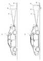
図5(a)は、例えば、車両1が駐車場に駐車している状態を示している。このとき、図5(a)に示すように障害物50は到達範囲S1と到達範囲S2の範囲内にあるため、反射波からは周波数成分Aおよび周波数成分Bの両方が抽出される。 FIG. 5A shows a state where the
そして、検出部13は、車両1の駐車中の間、障害物50があることを検出する。障害物50は、例えば、壁、縁石などの固定物であり、検出部13は、障害物50を一定時間検出することで、障害物50が固定物であると認識する。 Then, the
ここで、図5(a)に示した車両1が前進したとする。これにより、まず、障害物50が到達範囲S1の範囲外となり、反射波からは周波数成分Aが抽出されなくなる。検出部13は、周波数成分Aが抽出されなくなった時点から、車両1が走行した距離(以下、走行距離という)の計測を開始する。 Here, it is assumed that the
その後、さらに車両1が前進し、図5(b)示す状態になったとする。このとき、図5(b)に示すように障害物50は到達範囲S2の範囲外となるため、反射波からは周波数成分Bも抽出されなくなる。検出部13は、周波数成分Bが抽出されなくなった時点で走行距離の計測を終了する。例えば、図5(b)に示す距離45が、計測された走行距離に相当する。 Thereafter, it is assumed that the
次に、検出部13は、計測された走行距離が、予め定められた距離(例えば、図4の領域43を示す両矢印の長さ)と一致するか否かを判定する。 Next, the
計測された走行距離が距離と一致する場合、検出部13は、異常がないと判定し、その旨を示す検出結果情報を所定装置へ出力する。一方、計測された走行距離が閾値と一致しない場合、検出部13は、異常があると判定し、その旨を示す検出結果情報を所定装置へ出力する。 If the measured travel distance matches the distance, the
本変形例によれば、停車中の車両が発進した場合にも、異常を検出することができる。 According to this modification, an abnormality can be detected even when a stopped vehicle starts.
本発明は、障害物を検出する検出装置、検出方法、および検出プログラムに好適である。 The present invention is suitable for a detection device, a detection method, and a detection program for detecting an obstacle.
1 車両
2 超音波センサ
10 制御部
11 送受信制御部
12 抽出部
13 検出部
20 送信回路
30 受信回路
100 検出装置DESCRIPTION OF
Claims (9)
Translated fromJapanese前記超音波センサにより受信された反射波のうち受信レベルが所定閾値より大きい反射波から、周波数の成分を抽出する抽出部と、
前記成分の抽出結果に基づいて、障害物の有無および異常の有無を判定する検出部と、を備える、
検出装置。After transmitting a first transmission wave having a first frequency from an ultrasonic sensor used in a vehicle, the ultrasonic sensor receives the first frequency before receiving the reflected wave of the first transmission wave. A transmission unit for transmitting a second transmission wave of a different second frequency;
An extraction unit that extracts a frequency component from a reflected wave having a reception level greater than a predetermined threshold among the reflected waves received by the ultrasonic sensor;
A detection unit that determines the presence or absence of an obstacle and the presence or absence of an abnormality based on the extraction result of the component;
Detection device.
前記検出部は、
前記第1の周波数の成分と前記第2の周波数の成分の両方が抽出された場合、障害物があり、かつ、異常がないと判定し、
前記第1の周波数の成分と前記第2の周波数の成分のいずれも抽出されなかった場合、障害物がなく、かつ、異常がないと判定し、
前記第1の周波数の成分のみが抽出された場合、または、前記第2の周波数の成分のみが抽出された場合、障害物の検出が不可能であり、異常があると判定し、
前記第1の周波数の成分は、前記第1の周波数と同じ周波数、または、前記車両の走行によりドップラー効果が生じる場合に基づいて設定される第1の範囲内の周波数のいずれかを有する成分であり、
前記第2の周波数の成分は、前記第2の周波数と同じ周波数、または、前記車両の走行によりドップラー効果が生じる場合に基づいて設定される、前記第1の範囲と異なる第2の範囲内の周波数のいずれかを有する成分である、
請求項1に記載の検出装置。The amplitude level of the first transmission wave and the amplitude level of the second transmission wave are the same or substantially the same,
The detector is
When both the first frequency component and the second frequency component are extracted, it is determined that there is an obstacle and there is no abnormality,
If neither the first frequency component nor the second frequency component is extracted, it is determined that there is no obstacle and there is no abnormality,
When only the first frequency component is extracted, or when only the second frequency component is extracted, it is determined that an obstacle cannot be detected and there is an abnormality,
The component of the first frequency is a component having either the same frequency as the first frequency or a frequency within a first range that is set based on a case where a Doppler effect is generated by traveling of the vehicle. Yes,
The component of the second frequency is set based on the same frequency as the second frequency, or a second range different from the first range, which is set based on a case where a Doppler effect is generated by traveling of the vehicle. A component having any of the frequencies,
The detection device according to claim 1.
前記検出部は、
前記反射波が前記第1の送信波の到達範囲に対応する空間から来た反射波である場合において、
前記第1の周波数の成分および前記第2の周波数の成分の両方が抽出された場合、障害物があり、かつ、異常がないと判定し、
前記第1の周波数の成分および前記第2の周波数の成分のいずれも抽出されなかった場合、障害物がなく、かつ、異常がないと判定し、
前記第1の周波数の成分のみが抽出された場合、または、前記第2の周波数の成分のみが抽出された場合、障害物の検出が不可能であり、異常があると判定し、
前記第1の周波数の成分は、前記第1の周波数と同じ周波数、または、前記車両の走行によりドップラー効果が生じる場合に基づいて設定される第1の範囲内の周波数のいずれかを有する成分であり、
前記第2の周波数の成分は、前記第2の周波数と同じ周波数、または、前記車両の走行によりドップラー効果が生じる場合に基づいて設定される、前記第1の範囲と異なる第2の範囲内の周波数のいずれかを有する成分である、
請求項1に記載の検出装置。The amplitude level of the second transmission wave is greater than the amplitude level of the first transmission wave,
The detector is
In the case where the reflected wave is a reflected wave coming from a space corresponding to the reachable range of the first transmission wave,
When both the first frequency component and the second frequency component are extracted, it is determined that there is an obstacle and there is no abnormality,
If neither the first frequency component nor the second frequency component is extracted, it is determined that there is no obstacle and there is no abnormality,
When only the first frequency component is extracted, or when only the second frequency component is extracted, it is determined that an obstacle cannot be detected and there is an abnormality,
The component of the first frequency is a component having either the same frequency as the first frequency or a frequency within a first range that is set based on a case where a Doppler effect is generated by traveling of the vehicle. Yes,
The component of the second frequency is set based on the same frequency as the second frequency, or a second range different from the first range, which is set based on a case where a Doppler effect is generated by traveling of the vehicle. A component having any of the frequencies,
The detection device according to claim 1.
前記反射波が前記第1の送信波の到達範囲外かつ前記第2の送信波の到達範囲内に対応する空間から来た反射波である場合において、
前記第1の周波数の成分が抽出された場合、障害物の検出が不可能であり、異常があると判定し、
前記第1の周波数の成分が抽出されず、かつ、前記第2の周波数の成分が抽出された場合、障害物があり、かつ、異常がないと判定し、
前記第1の周波数の成分が抽出されず、かつ、前記第2の周波数の成分が抽出されなかった場合、障害物がなく、かつ、異常がないと判定する、
請求項3に記載の検出装置。The detector is
In the case where the reflected wave is a reflected wave coming from a space corresponding to outside the reachable range of the first transmitted wave and within the reachable range of the second transmitted wave,
When the first frequency component is extracted, it is impossible to detect an obstacle, and it is determined that there is an abnormality.
If the component of the first frequency is not extracted and the component of the second frequency is extracted, it is determined that there is an obstacle and there is no abnormality,
If the component of the first frequency is not extracted and the component of the second frequency is not extracted, it is determined that there is no obstacle and there is no abnormality.
The detection device according to claim 3.
前記反射波が前記第2の送信波の到達範囲外に対応する空間から来た反射波である場合において、
前記第1の周波数の成分および前記第2の周波数の成分の少なくとも一方が抽出された場合、異常があると判定し、
前記第1の周波数の成分および第2の周波数の成分のいずれも抽出されなかった場合、異常がないと判定する、
請求項3または4に記載の検出装置。The detector is
In the case where the reflected wave is a reflected wave coming from a space corresponding to outside the reachable range of the second transmission wave,
When at least one of the first frequency component and the second frequency component is extracted, it is determined that there is an abnormality,
When neither the first frequency component nor the second frequency component is extracted, it is determined that there is no abnormality.
The detection device according to claim 3 or 4.
前記検出部は、
前記車両の停車中において、障害物が前記第1の送信波の到達範囲内かつ前記第2の周波数の到達範囲内にあり、前記反射波から前記第1の周波数の成分および前記第2の周波数の成分の両方が抽出された場合、前記障害物を検出し、
停車中の前記車両が走行を開始した場合、前記第1の周波数の成分が抽出されなくなってから前記第2の周波数の成分が抽出されなくなるまでの前記車両の走行距離を計測し、
前記走行距離が予め定められた距離と一致する場合、異常がないと判定し、
前記走行距離が前記予め定められた距離と一致しない場合、異常があると判定する、
請求項1に記載の検出装置。The amplitude level of the second transmission wave is greater than the amplitude level of the first transmission wave,
The detector is
While the vehicle is stopped, the obstacle is in the reach range of the first transmission wave and the reach range of the second frequency, and the component of the first frequency and the second frequency from the reflected wave If both of the components are extracted, the obstacle is detected,
When the stopped vehicle starts to travel, the travel distance of the vehicle from when the first frequency component is no longer extracted until the second frequency component is not extracted is measured,
If the mileage matches a predetermined distance, determine that there is no abnormality,
When the travel distance does not match the predetermined distance, it is determined that there is an abnormality.
The detection device according to claim 1.
障害物の有無および異常の有無の少なくとも一方を示す情報を所定装置へ出力する、
請求項1から6のいずれか1項に記載の検出装置。The detector is
Outputting information indicating at least one of the presence or absence of an obstacle and the presence or absence of an abnormality to a predetermined device;
The detection device according to any one of claims 1 to 6.
前記超音波センサにより受信された反射波のうち受信レベルが所定閾値より大きい反射波から、周波数の成分を抽出するステップと、
前記成分の抽出結果に基づいて、障害物の有無および異常の有無を判定するステップと、を含む、
検出方法。After transmitting a first transmission wave having a first frequency from an ultrasonic sensor used in a vehicle, the ultrasonic sensor receives the first frequency before receiving the reflected wave of the first transmission wave. Transmitting a second transmission wave of a different second frequency;
Extracting a frequency component from a reflected wave having a reception level greater than a predetermined threshold among the reflected waves received by the ultrasonic sensor;
Determining the presence or absence of obstacles and the presence or absence of abnormalities based on the extraction results of the components,
Detection method.
前記超音波センサにより受信された反射波のうち受信レベルが所定閾値より大きい反射波から、周波数の成分を抽出する処理と、
前記成分の抽出結果に基づいて、障害物の有無および異常の有無を判定する処理と、
をコンピュータに実行させるプログラム。After transmitting a first transmission wave having a first frequency from an ultrasonic sensor used in a vehicle, the ultrasonic sensor receives the first frequency before receiving the reflected wave of the first transmission wave. Processing for transmitting a second transmission wave of a different second frequency;
A process of extracting a frequency component from a reflected wave having a reception level greater than a predetermined threshold among the reflected waves received by the ultrasonic sensor;
A process for determining the presence or absence of an obstacle and the presence or absence of an abnormality based on the extraction result of the component;
A program that causes a computer to execute.
Priority Applications (1)
| Application Number | Priority Date | Filing Date | Title |
|---|---|---|---|
| JP2016194581AJP2018054580A (en) | 2016-09-30 | 2016-09-30 | Detection apparatus, detection method, and detection program |
Applications Claiming Priority (1)
| Application Number | Priority Date | Filing Date | Title |
|---|---|---|---|
| JP2016194581AJP2018054580A (en) | 2016-09-30 | 2016-09-30 | Detection apparatus, detection method, and detection program |
Publications (1)
| Publication Number | Publication Date |
|---|---|
| JP2018054580Atrue JP2018054580A (en) | 2018-04-05 |
Family
ID=61833002
Family Applications (1)
| Application Number | Title | Priority Date | Filing Date |
|---|---|---|---|
| JP2016194581APendingJP2018054580A (en) | 2016-09-30 | 2016-09-30 | Detection apparatus, detection method, and detection program |
Country Status (1)
| Country | Link |
|---|---|
| JP (1) | JP2018054580A (en) |
Cited By (2)
| Publication number | Priority date | Publication date | Assignee | Title |
|---|---|---|---|---|
| JP2022507748A (en)* | 2018-11-19 | 2022-01-18 | ヴァレオ・シャルター・ウント・ゼンゾーレン・ゲーエムベーハー | Methods and systems for determining the state of ultrasonic sensor diaphragms |
| JP7526882B2 (en) | 2020-09-15 | 2024-08-01 | ヴァレオ・シャルター・ウント・ゼンゾーレン・ゲーエムベーハー | Checking the positioning of ultrasonic sensors on a vehicle |
- 2016
- 2016-09-30JPJP2016194581Apatent/JP2018054580A/enactivePending
Cited By (3)
| Publication number | Priority date | Publication date | Assignee | Title |
|---|---|---|---|---|
| JP2022507748A (en)* | 2018-11-19 | 2022-01-18 | ヴァレオ・シャルター・ウント・ゼンゾーレン・ゲーエムベーハー | Methods and systems for determining the state of ultrasonic sensor diaphragms |
| JP7209834B2 (en) | 2018-11-19 | 2023-01-20 | ヴァレオ・シャルター・ウント・ゼンゾーレン・ゲーエムベーハー | Method and system for determining the state of a diaphragm of an ultrasonic sensor |
| JP7526882B2 (en) | 2020-09-15 | 2024-08-01 | ヴァレオ・シャルター・ウント・ゼンゾーレン・ゲーエムベーハー | Checking the positioning of ultrasonic sensors on a vehicle |
Similar Documents
| Publication | Publication Date | Title |
|---|---|---|
| JP6715456B2 (en) | Detecting device, detecting method, and detecting program | |
| US10571555B2 (en) | Method for detecting a blocked state of an ultrasonic sensor of a motor vehicle, ultrasonic sensor apparatus and motor vehicle | |
| JP6293901B2 (en) | Method for detecting target echo in reception signal of ultrasonic sensor of automobile, ultrasonic sensor device and automobile | |
| JP6445419B2 (en) | Object detection apparatus and object detection method | |
| CN103930794B (en) | Method for operating a sensor | |
| JP6089585B2 (en) | Obstacle detection device | |
| JP6073646B2 (en) | Correction value setting device and distance detection device | |
| US20160209509A1 (en) | Vehicle-dedicated object detection device | |
| US20190212444A1 (en) | Detection device, detection method, and recording medium | |
| JP2018054580A (en) | Detection apparatus, detection method, and detection program | |
| CN111220990A (en) | Obstacle detection method, parameter configuration method and equipment of ultrasonic sensor | |
| JP2018105702A (en) | Object detection device | |
| JP7501673B2 (en) | Object detection device | |
| CN117916628A (en) | Method for characterizing objects in the surroundings of a motor vehicle | |
| CN117546048A (en) | Object detection device and object detection method | |
| JP7487534B2 (en) | Object detection device | |
| JP2016194451A (en) | Obstacle detection device and ultrasonic sensor adjustment method | |
| JP2022027091A (en) | Control method of ultrasonic object detection device, ultrasonic object detection device, and control program of ultrasonic object detection device | |
| US11994583B2 (en) | Object detection device | |
| KR102075927B1 (en) | Apparatus and method for parking assistance | |
| US11860274B2 (en) | Object detection device | |
| JP2002006036A (en) | Sensing method for reflected waves of ultrasonic waves and ultrasonic sensor device | |
| JP2002350540A (en) | Ultrasonic wave propagation time calculator and obstacle detection system for vehicle | |
| WO2025074779A1 (en) | Object detection device | |
| CN117480406A (en) | Object detection system and object detection device |
Legal Events
| Date | Code | Title | Description |
|---|---|---|---|
| RD02 | Notification of acceptance of power of attorney | Free format text:JAPANESE INTERMEDIATE CODE: A7422 Effective date:20190625 |