JP2018052356A - Bicycle operation device - Google Patents
Bicycle operation deviceDownload PDFInfo
- Publication number
- JP2018052356A JP2018052356AJP2016191956AJP2016191956AJP2018052356AJP 2018052356 AJP2018052356 AJP 2018052356AJP 2016191956 AJP2016191956 AJP 2016191956AJP 2016191956 AJP2016191956 AJP 2016191956AJP 2018052356 AJP2018052356 AJP 2018052356A
- Authority
- JP
- Japan
- Prior art keywords
- housing
- bicycle
- clamp
- operating
- operation unit
- Prior art date
- Legal status (The legal status is an assumption and is not a legal conclusion. Google has not performed a legal analysis and makes no representation as to the accuracy of the status listed.)
- Pending
Links
- 238000003780insertionMethods0.000claimsdescription24
- 230000037431insertionEffects0.000claimsdescription24
- 230000002093peripheral effectEffects0.000claimsdescription13
- 238000006073displacement reactionMethods0.000claimsdescription6
- 239000000463materialSubstances0.000claimsdescription5
- 239000011347resinSubstances0.000claimsdescription3
- 229920005989resinPolymers0.000claimsdescription3
- 230000004048modificationEffects0.000description14
- 238000012986modificationMethods0.000description14
- 230000005540biological transmissionEffects0.000description13
- 239000000725suspensionSubstances0.000description10
- 230000008878couplingEffects0.000description4
- 238000010168coupling processMethods0.000description4
- 238000005859coupling reactionMethods0.000description4
- 239000003795chemical substances by applicationSubstances0.000description2
- 238000010586diagramMethods0.000description2
- 239000010720hydraulic oilSubstances0.000description2
- XAGFODPZIPBFFR-UHFFFAOYSA-NaluminiumChemical compound[Al]XAGFODPZIPBFFR-UHFFFAOYSA-N0.000description1
- 229910052782aluminiumInorganic materials0.000description1
- 230000008094contradictory effectEffects0.000description1
- 230000007935neutral effectEffects0.000description1
- 239000003921oilSubstances0.000description1
Images


Classifications
- B—PERFORMING OPERATIONS; TRANSPORTING
- B62—LAND VEHICLES FOR TRAVELLING OTHERWISE THAN ON RAILS
- B62M—RIDER PROPULSION OF WHEELED VEHICLES OR SLEDGES; POWERED PROPULSION OF SLEDGES OR SINGLE-TRACK CYCLES; TRANSMISSIONS SPECIALLY ADAPTED FOR SUCH VEHICLES
- B62M25/00—Actuators for gearing speed-change mechanisms specially adapted for cycles
- B62M25/02—Actuators for gearing speed-change mechanisms specially adapted for cycles with mechanical transmitting systems, e.g. cables, levers
- B62M25/04—Actuators for gearing speed-change mechanisms specially adapted for cycles with mechanical transmitting systems, e.g. cables, levers hand actuated
- B—PERFORMING OPERATIONS; TRANSPORTING
- B62—LAND VEHICLES FOR TRAVELLING OTHERWISE THAN ON RAILS
- B62K—CYCLES; CYCLE FRAMES; CYCLE STEERING DEVICES; RIDER-OPERATED TERMINAL CONTROLS SPECIALLY ADAPTED FOR CYCLES; CYCLE AXLE SUSPENSIONS; CYCLE SIDE-CARS, FORECARS, OR THE LIKE
- B62K23/00—Rider-operated controls specially adapted for cycles, i.e. means for initiating control operations, e.g. levers, grips
- B62K23/02—Rider-operated controls specially adapted for cycles, i.e. means for initiating control operations, e.g. levers, grips hand actuated
- B62K23/06—Levers
- B—PERFORMING OPERATIONS; TRANSPORTING
- B62—LAND VEHICLES FOR TRAVELLING OTHERWISE THAN ON RAILS
- B62K—CYCLES; CYCLE FRAMES; CYCLE STEERING DEVICES; RIDER-OPERATED TERMINAL CONTROLS SPECIALLY ADAPTED FOR CYCLES; CYCLE AXLE SUSPENSIONS; CYCLE SIDE-CARS, FORECARS, OR THE LIKE
- B62K23/00—Rider-operated controls specially adapted for cycles, i.e. means for initiating control operations, e.g. levers, grips
- B62K23/02—Rider-operated controls specially adapted for cycles, i.e. means for initiating control operations, e.g. levers, grips hand actuated
- B62K23/04—Twist grips
- B—PERFORMING OPERATIONS; TRANSPORTING
- B62—LAND VEHICLES FOR TRAVELLING OTHERWISE THAN ON RAILS
- B62L—BRAKES SPECIALLY ADAPTED FOR CYCLES
- B62L3/00—Brake-actuating mechanisms; Arrangements thereof
- B62L3/02—Brake-actuating mechanisms; Arrangements thereof for control by a hand lever
- B—PERFORMING OPERATIONS; TRANSPORTING
- B62—LAND VEHICLES FOR TRAVELLING OTHERWISE THAN ON RAILS
- B62L—BRAKES SPECIALLY ADAPTED FOR CYCLES
- B62L3/00—Brake-actuating mechanisms; Arrangements thereof
- B62L3/02—Brake-actuating mechanisms; Arrangements thereof for control by a hand lever
- B62L3/023—Brake-actuating mechanisms; Arrangements thereof for control by a hand lever acting on fluid pressure systems
- B—PERFORMING OPERATIONS; TRANSPORTING
- B62—LAND VEHICLES FOR TRAVELLING OTHERWISE THAN ON RAILS
- B62M—RIDER PROPULSION OF WHEELED VEHICLES OR SLEDGES; POWERED PROPULSION OF SLEDGES OR SINGLE-TRACK CYCLES; TRANSMISSIONS SPECIALLY ADAPTED FOR SUCH VEHICLES
- B62M25/00—Actuators for gearing speed-change mechanisms specially adapted for cycles
- B62M25/08—Actuators for gearing speed-change mechanisms specially adapted for cycles with electrical or fluid transmitting systems
Landscapes
- Engineering & Computer Science (AREA)
- Mechanical Engineering (AREA)
- Chemical & Material Sciences (AREA)
- Combustion & Propulsion (AREA)
- Transportation (AREA)
- Physics & Mathematics (AREA)
- Fluid Mechanics (AREA)
- Steering Devices For Bicycles And Motorcycles (AREA)
- Mechanical Control Devices (AREA)
Abstract
Description
Translated fromJapanese本発明は、自転車操作装置に関する。 The present invention relates to a bicycle operating device.
自転車のハンドルバーに取り付けられるクランプが知られている。一例では、クランプは、ブレーキレバーアッセンブリおよびシフトレバーアッセンブリ等の操作ユニットを取り付け可能である。特許文献1は、従来のクランプの一例を開示している。 Clamps that are attached to bicycle handlebars are known. In one example, the clamp can be attached to an operation unit such as a brake lever assembly and a shift lever assembly. Patent Document 1 discloses an example of a conventional clamp.
クランプに取り付けられる操作ユニットを容易に操作できることが望まれる。
本発明の目的は、操作ユニットを容易に操作できる自転車操作装置を提供することである。It is desirable that the operation unit attached to the clamp can be easily operated.
An object of the present invention is to provide a bicycle operation device that can easily operate an operation unit.
(1)本発明に従う自転車操作装置の一形態は、自転車のハンドルバーに取り付け可能なクランプと、操作レバーを含み、前記クランプに連結される第1操作ユニットと、電気スイッチを含み、前記クランプに取り付けられる第2操作ユニットと、を備える。
第2操作ユニットが電気スイッチを含むため、第2操作ユニットを容易に操作できる。(1) One form of the bicycle operating device according to the present invention includes a clamp attachable to a handlebar of a bicycle, an operating lever, a first operating unit coupled to the clamp, an electric switch, and the clamp A second operation unit to be attached.
Since the second operation unit includes an electric switch, the second operation unit can be easily operated.
(2)前記(1)に記載の自転車操作装置において、前記第2操作ユニットは、前記クランプに着脱可能に取り付けられる。
このため、第2操作ユニットを容易に着脱できる。(2) In the bicycle operating device according to (1), the second operating unit is detachably attached to the clamp.
For this reason, the second operation unit can be easily attached and detached.
(3)前記(1)または(2)に記載の自転車操作装置において、前記第1操作ユニットは、シリンダ室と、前記操作レバーへの入力に伴って前記シリンダ室内を移動可能なピストンと、を含む。
このため、油圧を利用した第1操作ユニットを実現できる。(3) In the bicycle operating device according to (1) or (2), the first operating unit includes a cylinder chamber and a piston that can move in the cylinder chamber in accordance with an input to the operating lever. Including.
For this reason, the 1st operation unit using oil pressure is realizable.
(4)前記(1)〜(3)のいずれか一項に記載の自転車操作装置において、前記第2操作ユニットは、無線通信部をさらに含む。
このため、第2操作ユニットに関する配線を簡素化できる。(4) In the bicycle operating device according to any one of (1) to (3), the second operating unit further includes a wireless communication unit.
For this reason, wiring relating to the second operation unit can be simplified.
(5)前記(1)〜(4)のいずれか一項に記載の自転車操作装置において、前記第2操作ユニットは、電源をさらに含む。
このため、自転車操作装置の外部の電源と自転車操作装置との電気的な接続が不要となり、自転車操作装置の構成を簡素化できる。(5) In the bicycle operating device according to any one of (1) to (4), the second operating unit further includes a power source.
This eliminates the need for an electrical connection between the power source external to the bicycle operating device and the bicycle operating device, thereby simplifying the configuration of the bicycle operating device.
(6)前記(1)〜(5)のいずれか一項に記載の自転車操作装置において、前記第2操作ユニットは、報知部をさらに含む。
このため、ユーザに情報を報知できる。(6) In the bicycle operation device according to any one of (1) to (5), the second operation unit further includes a notification unit.
For this reason, information can be notified to the user.
(7)前記(1)〜(6)のいずれか一項に記載の自転車操作装置において、前記クランプは、第1クランプ部、前記第1クランプ部に回転可能に連結される第2クランプ部、および、前記ハンドルバーを挟持できるように前記第1クランプ部と前記第2クランプ部とを連結部材を含む。
このため、自転車のハンドルバーとクランプとが強く連結される。(7) In the bicycle operating device according to any one of (1) to (6), the clamp includes a first clamp part, a second clamp part rotatably connected to the first clamp part, In addition, the first clamp portion and the second clamp portion include a connecting member so that the handle bar can be clamped.
For this reason, the handlebar and the clamp of the bicycle are strongly connected.
(8)前記(7)に記載の自転車操作装置において、前記第1操作ユニットは、前記第1クランプ部と前記第2クランプ部とによって挟持される被挟持部を含む。
このため、クランプが自転車のハンドルバーと第1操作ユニットとを併せて挟み込むことができる。(8) In the bicycle operating device according to (7), the first operation unit includes a sandwiched portion that is sandwiched between the first clamp portion and the second clamp portion.
For this reason, the clamp can sandwich the handlebar of the bicycle and the first operation unit together.
(9)前記(8)に記載の自転車操作装置において、前記第1操作ユニットの前記被挟持部は、前記連結部材を挿入可能な挿入部を含む。
このため、クランプと第1操作ユニットとが強く連結される。(9) In the bicycle operating device according to (8), the sandwiched portion of the first operating unit includes an insertion portion into which the connecting member can be inserted.
For this reason, a clamp and a 1st operation unit are connected strongly.
(10)前記(7)〜(9)のいずれか一項に記載の自転車操作装置において、前記第2操作ユニットは、前記第1クランプ部および前記第2クランプ部の一方に取り付けられる。
このため、第2操作ユニットがクランプに取り付けられた状態でクランプをハンドルバーに取り付けることができる。(10) In the bicycle operation device according to any one of (7) to (9), the second operation unit is attached to one of the first clamp portion and the second clamp portion.
For this reason, a clamp can be attached to a handlebar in the state where the 2nd operation unit was attached to a clamp.
(11)前記(10)に記載の自転車操作装置において、前記第1クランプ部および前記第2クランプ部の他方に連結される第3操作ユニットをさらに備える。
このため、ユーザが第2操作ユニットおよび第3操作ユニットを同じ手で操作できる。(11) The bicycle operation device according to (10), further including a third operation unit coupled to the other of the first clamp portion and the second clamp portion.
For this reason, the user can operate the second operation unit and the third operation unit with the same hand.
(12)前記(1)〜(11)のいずれか一項に記載の自転車操作装置において、前記クランプと前記第2操作ユニットとの間に設けられるアダプターをさらに備える。
このため、第2操作ユニットをクランプに容易に取り付けることができる。(12) The bicycle operation device according to any one of (1) to (11), further including an adapter provided between the clamp and the second operation unit.
For this reason, the second operation unit can be easily attached to the clamp.
(13)前記(12)に記載の自転車操作装置において、前記アダプターは、前記クランプの外周面に取り付けられる。
このため、アダプターをクランプに容易に取り付けることができる。(13) In the bicycle operating device according to (12), the adapter is attached to an outer peripheral surface of the clamp.
For this reason, an adapter can be easily attached to a clamp.
(14)前記(12)または(13)自転車操作装置において、前記アダプターは、前記クランプに取り付けられる第1取付部と、前記第1取付部から前記クランプの中心軸方向に延びる第2取付部とを含み、前記第2操作ユニットは、前記第2取付部に取り付けられる。
このため、第2操作ユニットとクランプとが接触しにくい。(14) In the bicycle operating device according to (12) or (13), the adapter includes a first attachment portion attached to the clamp, and a second attachment portion extending from the first attachment portion in a central axis direction of the clamp. The second operation unit is attached to the second attachment portion.
For this reason, it is difficult for the second operation unit and the clamp to contact each other.
(15)前記(14)に記載の自転車操作装置において、前記中心軸方向に沿って前記第2操作ユニットの位置を調整可能な第1位置調整機構をさらに備える。
このため、第2操作ユニットの位置を容易に調整できる。(15) The bicycle operation device according to (14), further including a first position adjustment mechanism capable of adjusting a position of the second operation unit along the central axis direction.
For this reason, the position of the second operation unit can be easily adjusted.
(16)前記(15)に記載の自転車操作装置において、前記第1位置調整機構は、前記第2操作ユニットを前記中心軸方向に案内するガイド構造を含み、前記ガイド構造は、前記中心軸方向に延びる凹部と凸部とを含み、前記凹部は、前記第2取付部および前記第2操作ユニットの一方に設けられ、前記凸部は、前記第2取付部および前記第2操作ユニットの他方に設けられる。
このため、第2操作ユニットの位置を連続的に調整できる。(16) In the bicycle operating device according to (15), the first position adjustment mechanism includes a guide structure that guides the second operating unit in the central axis direction, and the guide structure is in the central axis direction. And the concave portion is provided on one of the second attachment portion and the second operation unit, and the convex portion is provided on the other of the second attachment portion and the second operation unit. Provided.
For this reason, the position of the second operation unit can be continuously adjusted.
(17)前記(12)〜(16)のいずれか一項に記載の自転車操作装置において、前記クランプの外周面に沿って前記アダプターの位置を調整可能な第2位置調整機構をさらに備える。
このため、第2操作ユニットの位置を容易に調整できる。(17) The bicycle operation device according to any one of (12) to (16), further including a second position adjustment mechanism capable of adjusting a position of the adapter along an outer peripheral surface of the clamp.
For this reason, the position of the second operation unit can be easily adjusted.
(18)前記(1)〜(17)のいずれか一項に記載の自転車操作装置において、前記電気スイッチは、少なくとも第1スイッチおよび第2スイッチを含む。
このため、ユーザが第1スイッチおよび第2スイッチを同じ手で操作できる。(18) In the bicycle operating device according to any one of (1) to (17), the electrical switch includes at least a first switch and a second switch.
For this reason, the user can operate the first switch and the second switch with the same hand.
(19)前記(18)に記載の自転車操作装置において、第1方向への変位に応じて前記第1スイッチを操作し、前記第1方向とは異なる第2方向への変位に応じて前記第2スイッチを操作する、第1操作部材をさらに含む。
このため、第2操作ユニットの構成を簡素化できる。(19) In the bicycle operating device according to (18), the first switch is operated in response to a displacement in a first direction, and the first switch is operated in response to a displacement in a second direction different from the first direction. A first operating member for operating two switches is further included.
For this reason, the structure of the 2nd operation unit can be simplified.
(20)前記(18)に記載の自転車操作装置において、前記第2操作ユニットは、前記第1スイッチを操作するための第1操作部材と、前記第2スイッチを操作するための第2操作部材と、をさらに含む。
このため、第1操作部材の構成を簡素化できる。(20) In the bicycle operating device according to (18), the second operating unit includes a first operating member for operating the first switch and a second operating member for operating the second switch. And further including.
For this reason, the structure of the 1st operation member can be simplified.
(21)前記(20)に記載の自転車操作装置において、前記第1操作部材は、第1軸まわりに揺動可能な第1レバーを含み、前記第2操作部材は、第2軸まわりに揺動可能な第2レバーを含む。
このため、第1操作部材および第2操作部材を容易に操作できる。(21) In the bicycle operating device according to (20), the first operating member includes a first lever swingable about a first axis, and the second operating member swings about a second axis. A movable second lever is included.
For this reason, the first operating member and the second operating member can be easily operated.
(22)前記(21)に記載の自転車操作装置において、前記第1レバーは、前記第1軸に直交する第1動作面に沿って揺動し、前記第2レバーは、前記第2軸に直交する第2動作面に沿って揺動し、前記第1動作面と前記第2動作面とが形成する角度は、20°以上かつ70°以下である。
このため、第1操作部材および第2操作部材を容易に操作できる。(22) In the bicycle operating device according to (21), the first lever swings along a first operation surface orthogonal to the first axis, and the second lever moves to the second axis. The angle formed by the first motion surface and the second motion surface is 20 ° or more and 70 ° or less.
For this reason, the first operating member and the second operating member can be easily operated.
(23)前記(20)〜(22)のいずれか一項に記載の自転車操作装置において、前記第1操作部材は、ユーザの第1の指によって操作されるように構成され、前記第2操作部材は、前記ユーザの第2の指によって操作されるように構成される。
このため、第1操作部材および第2操作部材を容易に操作できる。(23) In the bicycle operation device according to any one of (20) to (22), the first operation member is configured to be operated by a first finger of a user, and the second operation The member is configured to be operated by the user's second finger.
For this reason, the first operating member and the second operating member can be easily operated.
(24)前記(1)〜(17)のいずれか一項に記載の自転車操作装置において、前記電気スイッチは、第1スイッチのみを含み、前記第2操作ユニットは、前記第1スイッチを操作するための第1操作部材をさらに含む。
このため、第2操作ユニットの構成を簡素化できる。(24) In the bicycle operating device according to any one of (1) to (17), the electrical switch includes only a first switch, and the second operating unit operates the first switch. The 1st operation member for is further included.
For this reason, the structure of the 2nd operation unit can be simplified.
(25)前記(19)〜(24)のいずれか一項に記載の自転車操作装置において、前記第1操作部材の初期位置を調整可能な操作位置調整機構をさらに備える。
このため、第1操作部材の初期位置を容易に調整できる。(25) The bicycle operation device according to any one of (19) to (24), further including an operation position adjustment mechanism capable of adjusting an initial position of the first operation member.
For this reason, the initial position of the first operating member can be easily adjusted.
(26)前記(19)〜(25)のいずれか一項に記載の自転車操作装置において、前記第1操作部材は、第1スイッチを操作するための操作面と、前記第1操作部材において前記操作面以外の位置に設けられる追加操作部材と、を含む。
このため、ユーザが第1スイッチおよび追加操作部材を同じ手で操作できる。(26) In the bicycle operation device according to any one of (19) to (25), the first operation member includes an operation surface for operating a first switch, and the first operation member. And an additional operation member provided at a position other than the operation surface.
For this reason, the user can operate the first switch and the additional operation member with the same hand.
(27)前記(19)〜(26)のいずれか一項に記載の自転車操作装置において、前記クランプの中心軸方向において前記クランプに対して前記第1操作部材を一方側または他方側に付け替え可能な付け替え構造をさらに備える。
このため、クランプに対する第1操作部材の位置を選択できる。(27) In the bicycle operating device according to any one of (19) to (26), the first operating member can be changed to one side or the other side with respect to the clamp in the central axis direction of the clamp. A replacement structure is further provided.
For this reason, the position of the first operating member with respect to the clamp can be selected.
(28)前記(4)に記載の自転車操作装置において、前記第2操作ユニットは、前記無線通信部を収容し、前記無線通信部が出力する電波を透過可能なハウジングをさらに含む。
このため、無線通信部が良好な電波状態で通信できる。(28) In the bicycle operating device according to (4), the second operating unit further includes a housing that houses the wireless communication unit and is capable of transmitting radio waves output from the wireless communication unit.
For this reason, the wireless communication unit can communicate in a good radio wave state.
(29)前記(28)に記載の自転車操作装置において、前記ハウジングは、前記ハウジングの半分よりも前の部分であるハウジング前部と前記ハウジングの半分よりも後ろの部分であるハウジング後部とを有し、前記無線通信部は、前記ハウジング後部に収容される。
このため、ハウジング前部に他の要素を配置するためのスペースが広くなる。(29) In the bicycle operating device according to (28), the housing has a housing front portion that is a portion in front of a half of the housing and a housing rear portion that is a portion in the rear of the half of the housing. And the said radio | wireless communication part is accommodated in the said housing rear part.
For this reason, the space for arrange | positioning another element in a housing front part becomes large.
(30)前記(28)に記載の自転車操作装置において、前記ハウジングは、前記ハウジングの半分よりも前の部分であるハウジング前部と前記ハウジングの半分よりも後ろの部分であるハウジング後部とを有し、前記無線通信部は、前記ハウジング前部に収容される。
このため、ハウジング後部に他の要素を配置するためのスペースが広くなる。(30) In the bicycle operating device according to (28), the housing has a housing front portion that is a front portion of a half of the housing and a housing rear portion that is a portion of the rear of the housing. And the said radio | wireless communication part is accommodated in the said housing front part.
For this reason, the space for arrange | positioning another element in a housing rear part becomes wide.
(31)前記(28)〜(30)のいずれか一項に記載の自転車操作装置において、前記ハウジングは、前記ハウジングの半分よりも上の部分であるハウジング上部と前記ハウジングの半分よりも下の部分であるハウジング下部とを有し、前記無線通信部は、前記ハウジング上部に収容される。
このため、ハウジング下部に他の要素を配置するためのスペースが広くなる。(31) In the bicycle operating device according to any one of (28) to (30), the housing includes a housing upper portion that is a portion above the half of the housing and a portion below the half of the housing. A lower housing portion, and the wireless communication unit is accommodated in the upper housing portion.
For this reason, the space for arrange | positioning another element under a housing becomes wide.
(32)前記(28)〜(30)のいずれか一項に記載の自転車操作装置において、前記ハウジングは、前記ハウジングの半分よりも上の部分であるハウジング上部と前記ハウジングの半分よりも下の部分であるハウジング下部とを有し、前記無線通信部は、前記ハウジング下部に収容される。
このため、ハウジング上部に他の要素を配置するためのスペースが広くなる。(32) In the bicycle operating device according to any one of (28) to (30), the housing includes a housing upper portion that is a portion above the half of the housing and a portion below the half of the housing. A lower housing part, and the wireless communication unit is housed in the lower housing part.
For this reason, the space for arrange | positioning another element on the housing upper part becomes wide.
(33)前記(28)〜(32)のいずれか一項に記載の自転車操作装置において、前記ハウジングは、樹脂材料を含む。
このため、第2操作ユニットを軽量化できる。(33) In the bicycle operating device according to any one of (28) to (32), the housing includes a resin material.
For this reason, a 2nd operation unit can be reduced in weight.
(34)前記(5)に記載の自転車操作装置において、前記第2操作ユニットは、前記電源を少なくとも部分的に収容可能な収容部を含むハウジングと、前記収容部に設けられる開口を少なくとも部分的に覆い、前記ハウジングに着脱可能な電源カバーとをさらに含む。
このため、電源を保護できる。(34) In the bicycle operating device according to (5), the second operation unit includes at least a part of a housing including a housing part capable of housing at least a part of the power source and an opening provided in the housing part. And a power supply cover detachably attached to the housing.
For this reason, a power supply can be protected.
(35)前記(34)に記載の自転車操作装置において、前記電源は、バッテリとバッテリホルダとを含み、前記バッテリは前記バッテリホルダに着脱可能に取り付けられる。
このため、バッテリを容易に交換できる。(35) In the bicycle operating device according to (34), the power source includes a battery and a battery holder, and the battery is detachably attached to the battery holder.
For this reason, the battery can be easily replaced.
上記自転車操作装置によれば、操作ユニットを容易に操作できる。 According to the bicycle operation device, the operation unit can be easily operated.
(第1実施形態)
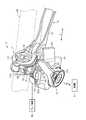
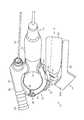
図1に示されるように、自転車操作装置10は、例えば、マウンテンバイクのハンドルバーHBに取り付けられる。自転車操作装置10は、クランプ12、第1操作ユニット14、および、第2操作ユニット16を備える。クランプ12は、自転車のハンドルバーHBに取り付け可能である。第1操作ユニット14は、クランプ12に連結される。第2操作ユニット16は、クランプ12に取り付けられる。一例では、第2操作ユニット16は、クランプ12に着脱可能に取り付けられる。第1操作ユニット14の一例は、油圧式のブレーキ装置BKを操作するブレーキ操作ユニットである。第2操作ユニット16の一例は、変速機STを操作するシフターである。変速機STは、フロント変速機およびリア変速機の少なくとも一方を含む。(First embodiment)
As shown in FIG. 1, the
自転車操作装置10は、アダプター18をさらに備える。アダプター18は、クランプ12の外周面12Aに取り付けられる。アダプター18は、クランプ12と第2操作ユニット16との間に設けられる。第2操作ユニット16は、アダプター18に着脱可能に取り付けられる。 The
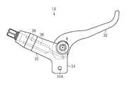
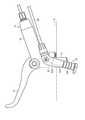
図2に示されるように、クランプ12は、第1クランプ部20、第2クランプ部22、および、連結部材24を含む。一例では、クランプ12の正面視におけるクランプ12の形状は、C形状である。クランプ12は、ヒンジ部26をさらに含む。ヒンジ部26は、連結ピン26Aを含む。第1クランプ部20および第2クランプ部22は、回転可能に互いに連結される。一例では、第1クランプ部20および第2クランプ部22は、連結ピン26Aまわりで回転できるように連結される。連結部材24は、ハンドルバーHB(図1参照)を挟持できるように、第1クランプ部20と第2クランプ部22とを連結する。連結部材24の一例は、ボルトである。クランプ12は、固定部材28をさらに含む。固定部材28の一例は、連結部材24に取り付け可能なナットである。 As shown in FIG. 2, the
第1クランプ部20は、第1挿入孔20Aを含む。第2クランプ部22は、第2挿入孔22Aおよび凹部22Bを含む。連結部材24は、各挿入孔20A、22Aに挿入される。凹部22Bは、第2クランプ部22の周方向に延びる。凹部22Bは、長孔22Cを含む。長孔22Cは、第2クランプ部22の周方向に延びる。 The
第1操作ユニット14は、ハウジング30および操作レバー32を含む。操作レバー32は、回転軸Rまわりでハウジング30に対して揺動可能である。第1操作ユニット14は、被挟持部34を含む。図示される例では、被挟持部34は、ハウジング30に一体に形成される。別の例では、被挟持部34は、ハウジング30と個別に形成され、ハウジング30に固定される。被挟持部34は、第1クランプ部20および第2クランプ部22によって挟持される。被挟持部34は、挿入部34Aを含む。挿入部34Aは、連結部材24が挿入可能である。被挟持部34が各クランプ部20、22に挟持され、連結部材24が第1挿入孔20A、挿入部34A、および、第2挿入孔22Aに挿入され、連結部材24の端部に固定部材28が取り付けられる。これにより、第1操作ユニット14がクランプ12に取り付けられる。 The
図3に示されるように、第1操作ユニット14は、シリンダ室36およびピストン38をさらに含む。ハウジング30はシリンダ室36を含む。シリンダ室36には、例えば作動油が満たされる。ピストン38は、操作レバー32への入力に伴ってシリンダ室36内を移動可能である。ピストン38は、操作レバー32に回転可能に連結される。操作レバー32が操作された場合、ピストン38が押し込まれ、ブレーキ装置BK(図1参照)に油圧が供給される。 As shown in FIG. 3, the
図4に示されるように、第2操作ユニット16は、電気スイッチ40を含む。第2操作ユニット16は、無線通信部42、電源44、報知部46、および、制御部48をさらに含む。無線通信部42は、自転車コンポーネントの一例である変速機ST(図1参照)と通信可能である。無線通信部42は、アンテナを含む。 As shown in FIG. 4, the
電源44は、電気スイッチ40、無線通信部42、報知部46、および、制御部48のそれぞれと電線(図示略)により接続される。報知部46は、情報を出力する。この情報は、例えば、第1操作ユニット14に関する情報、第2操作ユニット16に関する情報、および、外部機器から自転車操作装置10に入力された情報の少なくとも1つを含む。報知部46は、例えばLEDまたはブザーを含む。 The
電気スイッチ40は、無線通信部42に信号を送信可能である。電気スイッチ40は、少なくとも第1スイッチ40Aおよび第2スイッチ40Bを含む。電気スイッチ40は、第3スイッチ40Cをさらに含む。各スイッチ40A、40B、40Cは、制御部48にオン信号を出力する。制御部48は、各スイッチ40A、40B、40Cのオン信号を受信した場合、受信したオン信号に応じた制御信号を無線通信部42に出力する。無線通信部42は、受信した制御信号を例えば変速機STに出力する。別の例では、電気スイッチ40は、無線通信部42に信号を直接送信する。 The
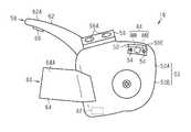
図5に示されるように、第2操作ユニット16は、ハウジング50を含む。ハウジング50は、無線通信部42を収容する。ハウジング50は、電気スイッチ40、電源44、報知部46、および、制御部48(ともに図4参照)をさらに収容する。ハウジング50は、無線通信部42が出力する電波を透過可能である。ハウジング50は、例えば樹脂材料を含む。 As shown in FIG. 5, the
ハウジング50は、ハウジング50の半分よりも前の部分であるハウジング前部50Aと、ハウジング50の半分よりも後ろの部分であるハウジング後部50Bとを有する。ハウジング50は、ハウジング50の半分よりも上の部分であるハウジング上部50Cと、ハウジング50の半分よりも下の部分であるハウジング下部50Dとを有する。 The
図6に示されるように、無線通信部42は、ハウジング後部50Bに収容される。図7に示されるように、無線通信部42は、ハウジング後部50Bかつハウジング下部50Dに収容される。無線通信部42は、ハウジング50に固定される。別の例では、無線通信部42は、ハウジング50に着脱可能に取り付けられる。 As shown in FIG. 6, the
図6に示されるように、第2操作ユニット16は、収容部50Eおよび電源カバー52を含む。収容部50Eは、電源44を少なくとも部分的に収容可能である。図6に示される収容部50Eは、電源44全体を収容する。収容部50Eは、ハウジング前部50Aかつハウジング下部50D(図7参照)に設けられる。電源44は、バッテリ44Aおよびバッテリホルダ44Bを含む。バッテリ44Aは、バッテリホルダ44Bに着脱可能に取り付けられる。電源カバー52は、収容部50Eに設けられる開口を少なくとも部分的に覆う。図6に示される電源カバー52は、収容部50Eの全体に亘って覆う。電源カバー52は、ハウジング50に着脱可能である。電源カバー52は、複数のボルト54を含む。ボルト54は、電源カバー52とハウジング50とを連結する。 As shown in FIG. 6, the
第2操作ユニット16は、凸部56をさらに含む。凸部56は、ハウジング50に固定される。一例では、凸部56は、ハウジング前部50Aかつハウジング下部50Dに固定される。別の例では、凸部56は、ハウジング50に着脱可能に取り付けられる。凸部56は、ハウジング50とは異なる材料により形成される。凸部56の材料の一例は、アルミニウムである。凸部56は、複数の固定孔56Aを含む。一例では、凸部56は、2つの固定孔56Aを含む。固定孔56Aの内周面には、雌ねじが形成される。ボルト84は、固定孔56Aと連結される。 The
第2操作ユニット16は、第1スイッチ40Aを操作するための第1操作部材58と、第2スイッチ40Bを操作するための第2操作部材60とをさらに含む。第1操作部材58は、例えばシフトアップのために操作される。第2操作部材60は、例えばシフトダウンのために操作される。 The
図7に示されるように、第1操作部材58は、第1レバー62を含む。第1レバー62は、第1軸J1まわりに揺動可能である。第1レバー62は、第1軸J1に直交する第1動作面に沿って揺動する。第2操作部材60は、第2レバー64を含む。第2レバー64は、第2軸J2まわりに揺動可能である。第2レバー64は、第2軸J2に直交する第2動作面に沿って揺動する。第1動作面と第2動作面とが形成する角度AGは、20°以上かつ70°以下である。一例では、角度AGは60°である。 As shown in FIG. 7, the
第2操作部材60は、第2スイッチ40B(図4参照)を操作するための操作面64Aを含む。一例では、操作面64Aは、第2レバー64に設けられる。第2レバー64は、回転部64Bおよび操作部64Cを含む。回転部64Bおよび操作部64Cは一体に形成される。回転部64Bは、第2軸J2と同軸に配置される。一例では、回転部64Bは、円筒である。第2操作部材60は、弾性部材(図示略)をさらに含む。弾性部材は、第2操作部材60を初期位置に戻す力を第2操作部材60に加えることができるように回転部64B内に設けられる。弾性部材の一例は、つるまきばねである。 The
第1操作部材58は、第1スイッチ40Aを操作するための操作面62Aと、第3スイッチ40Cを操作するための追加操作部材66とを含む。一例では、操作面62Aは、第1レバー62に設けられる。追加操作部材66は、第1操作部材58において操作面62A以外の位置に設けられる。操作面62A以外の位置の一例は、第1レバー62における操作面62Aの裏側の面である。追加操作部材66に関する第1の例では、追加操作部材66は、自転車操作装置10と自転車コンポーネントとをペアリングするために操作される。一例では、右側のハンドルバーHBに取り付けられた自転車操作装置10は、フロント変速機およびリア変速機の一方とペアリング可能である。左側のハンドルバーHBに取り付けられた自転車操作装置10は、フロント変速機およびリア変速機の他方とペアリング可能である。追加操作部材66に関する第2の例では、追加操作部材66は、電動サスペンションの動作状態を切り替えるため、または、電動シートポストの高さを調整するために操作される。 The
図5に示されるように、第1操作部材58は、回転部材68、一対の連結部70、および、ボルト72をさらに含む。第1レバー62は、収容部62Bを含む。収容部62Bは、回転部材68、連結部70、および、ボルト72を収容する。第1操作部材58は、弾性部材(図示略)をさらに含む。弾性部材は、第1操作部材58を初期位置に戻す力を第1操作部材58に加えることができるように回転部材68内に設けられる。弾性部材の一例は、つるまきばねである。 As shown in FIG. 5, the
回転部材68は、第1軸J1と同軸に配置される。回転部材68は、第1操作部材58の初期位置を調整するために用いられる目盛り68Aを含む。一例では、目盛り68Aは、回転部材68の表面の外周に沿うように設けられる。連結部70は、収容部62Bに収容された状態で第1レバー62に取り付けられる。連結部70は、第1操作部材58の初期位置を調整するために用いられる目盛り70Aを含む。連結部70は、弾性部材(図示略)をさらに含む。ボルト72が連結部70に挿入されることにより、弾性部材が圧縮され、圧縮された弾性部材の一部が回転部材68と連結され、連結部70と回転部材68とが連結される。この状態では、第1レバー62、連結部70、および、回転部材68が第1軸J1まわりで一体に回転する。 The rotating
第2操作ユニット16は、第1操作部材58の初期位置を調整可能な操作位置調整機構74をさらに備える。操作位置調整機構74は、第1レバー62、回転部材68、一対の連結部70、および、ボルト72を含む。操作位置調整機構74は、第1軸J1まわりで回転部材68に対する第1レバー62の回転位置を変更することにより、第1操作部材58の初期位置を調整する。連結部70に挿入されたボルト72が緩められた場合、連結部70と回転部材68とが連結されなくなる。この状態では、第1レバー62および連結部70と回転部材68とが第1軸J1まわりで相対回転する。このため、第1操作部材58の初期位置を調整できる。 The
図8に示されるように、第1操作部材58は、ユーザの第1の指F1によって操作されるように構成される。第2操作部材60は、ユーザの第2の指F2によって操作されるように構成される。第1レバー62が第1操作方向C1に押操作された場合、第1スイッチ40A(図4参照)がオン状態となる。第1レバー62が初期位置に戻された場合、第1スイッチ40Aがオフ状態となる。第2レバー64が第2操作方向C2に押操作された場合、第2スイッチ40B(図4参照)がオン状態となる。第2レバー64が初期位置に戻された場合、第2スイッチ40Bがオフ状態となる。 As shown in FIG. 8, the
図9に示されるように、アダプター18は、第1取付部76および第2取付部78を含む。アダプター18は、第1取付部76をクランプ12(図2参照)に取り付けるためのボルト80およびナット82と、第2取付部78に第2操作ユニット16(図2参照)を取り付けるためのボルト84とをさらに含む。 As shown in FIG. 9, the
第1取付部76は、クランプ12に取り付けられる。第1取付部76は、クランプ12の外周面12A(図2参照)に沿うように湾曲する。第1取付部76は、挿入孔76Aを含む。第2取付部78は、第1取付部76からクランプ12の中心軸方向Zに延びる。クランプ12の中心軸方向Zは、クランプ12の中心軸JC(図2参照)に沿った方向である。第2取付部78は、凹部78Aおよび挿入孔78Bを含む。凹部78Aは、中心軸方向Zに延びる溝である。凹部78Aの両端部は、それぞれ第2取付部78の端面において開口する。挿入孔78Bは、凹部78Aの底部に設けられる。 The
ボルト80およびナット82は、第1取付部76を挟み込む。ナット82は、挿入部82Aおよびフランジ82Bを含む。挿入部82Aは、第1取付部76の挿入孔76Aに挿入される。挿入部82Aの内周面には、雌ねじが設けられる。フランジ82Bは、クランプ12の内周面に沿うように湾曲する。ボルト80は、挿入部82Aの雌ねじに連結される。ボルト84は、第2取付部78の挿入孔78Bに挿入される。 The
図2に示されるように、第1取付部76は、長孔22Cを覆うようにクランプ12の外周面12Aに取り付けられる。ナット82(図9参照)は、クランプ12の内周面に取り付けられる。第1取付部76およびナット82は、クランプ12の第2クランプ部22を挟み込む。ナット82の挿入部82Aは(図9参照)、長孔22Cに挿入される。ボルト80は、長孔22Cに挿入されたナット82と連結される。ボルト80がナット82と連結されることにより、アダプター18がクランプ12の第2クランプ部22に取り付けられる。 As shown in FIG. 2, the
第2操作ユニット16は、第1クランプ部20および第2クランプ部22の一方に取り付けられる。図示される例では、第2操作ユニット16は、第2クランプ部22に取り付けられる。第2操作ユニット16は、第2取付部78に取り付けられる。第2操作ユニット16の凸部56が第2取付部78の凹部78Aに嵌め合わせられ、ボルト84が挿入孔78Bを介して一方の固定孔56Aに連結されることにより、第2操作ユニット16が第2取付部78に取り付けられる。他方の固定孔56Aにもボルト84が連結される。このため、他方の固定孔56A内に異物が侵入しにくい。別の例では、第2操作ユニット16は、第1クランプ部20に取り付けられる。アダプター18は、第1クランプ部20と第2操作ユニット16との間に設けられる。 The
図1に示されるように、自転車操作装置10は、第1位置調整機構86をさらに備える。自転車操作装置10は、第2位置調整機構88をさらに備える。第1位置調整機構86は、中心軸方向Zに沿って第2操作ユニット16の位置を調整可能である。第2位置調整機構88は、クランプ12の外周面12Aに沿ってアダプター18の位置を図10に示す位置P1から図11に示す位置P2までの範囲に亘り調整可能である。第2位置調整機構88は、クランプ12の長孔22C、第1取付部76、ボルト80、および、ナット82(図9参照)を含む。 As shown in FIG. 1, the
図1に示されるように、第1位置調整機構86は、第2操作ユニット16を中心軸方向Zに案内するガイド構造86Aを含む。ガイド構造86Aは、中心軸方向Zに延びる凹部78Aおよび凸部56を含む。凹部78Aは、アダプター18の第2取付部78に設けられる。凸部56は、第2操作ユニット16に設けられる。凸部56は、中心軸方向Zに沿って凹部78Aにスライド可能に嵌め合わせられる。別の例では、凹部78Aは第2操作ユニット16に設けられる。凸部56は、第2取付部78に設けられる。 As shown in FIG. 1, the first
(第2実施形態)
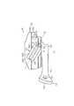
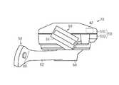
図12に示されるように、第2実施形態の自転車操作装置10は、第3操作ユニット90をさらに備える。第3操作ユニット90は、自転車コンポーネントを動作させるために操作される。図示される例では、第3操作ユニット90は、自転車のサスペンション(図示略)を動作させるために操作される。別の例では、第3操作ユニット90は、自転車のシートポストを動作させるために操作される。(Second Embodiment)
As shown in FIG. 12, the
第2操作ユニット16は、第1クランプ部20および第2クランプ部22の一方に取り付けられる。第3操作ユニット90は、第1クランプ部20および第2クランプ部22の他方に連結される。図示される例では、第2操作ユニット16は、第2クランプ部22に取り付けられる。第3操作ユニット90は、第1クランプ部20に連結される。別の例では、第2操作ユニット16は、第1クランプ部20に取り付けられる。第3操作ユニット90は、第2クランプ部22に連結される。 The
図13に示されるように、第3操作ユニット90は、ハウジング92、操作部材94、および、チューブ96を含む。ハウジング92は、第1クランプ部20に一体に設けられる。ハウジング92は、シリンダ室92Aを含む。シリンダ室92Aは、作動油で満たされる。操作部材94は、ピストン94Aを含む。ピストン94Aは、ハウジング92に対して移動可能な状態でシリンダ室92A内に設けられる。チューブ96の一端は、シリンダ室92Aに連結される。チューブ96の他端は、サスペンションに連結される。操作部材94が第1操作位置に操作された場合、サスペンションがロックアウト状態に保持される。操作部材94が第2操作位置に操作された場合、サスペンションのロックアウト状態が解除される。 As shown in FIG. 13, the
(変形例)
上記各実施形態に関する説明は、本発明の自転車操作装置が取り得る形態の例示であり、その形態を制限することを意図していない。本発明の自転車操作装置は、例えば以下に示される上記各実施形態の変形例、および、相互に矛盾しない少なくとも2つの変形例が組み合わせられた形態を取り得る。(Modification)
The description regarding each said embodiment is an illustration of the form which the bicycle operating device of this invention can take, and it does not intend restrict | limiting the form. The bicycle operating device of the present invention can take a form in which, for example, modifications of the above-described embodiments described below and at least two modifications not contradicting each other are combined.
・追加操作部材66が設けられる位置は、任意に変更可能である。一例では、追加操作部材66は、第2操作部材60に設けられる。好ましくは、追加操作部材66は、第2操作部材60における操作面64A以外の位置に設けられる。操作面64A以外の位置の一例は、第2操作部材60における操作面64Aの裏側の面である。 The position where the
・第2位置調整機構88の構成は任意に変更可能である。一例では、図14に示される第1変形例のように、第2位置調整機構88は、クランプ12の周方向に並ぶ複数の孔22Dを含む。 The configuration of the second
・第2操作ユニット16の構成は、任意に変更可能である。第1の例では、図15に示される第2変形例のように、第2操作ユニット16は、各スイッチ40A、40B、40Cのうちの第1スイッチ40Aのみを含み、第1スイッチ40Aを操作するための第1操作部材58をさらに含む。第2の例では、図16に示される第3変形例のように、第2操作ユニット16は、2つの弾性部材58Yをさらに含む。ハウジング50は、各スイッチ40A、40Bを収容する。各スイッチ40A、40Bは、第1操作部材58Xに対して互いに反対側に設けられる。第1操作部材58Xは、ハウジング50に対して揺動可能である。2つの弾性部材58Yは、第1操作部材58を中立位置に戻すように第1操作部材58に力を加える。第1操作部材58Xは、第1方向W1への変位に応じて第1スイッチ40Aを操作する。第1操作部材58Xは、第1方向W1とは異なる第2方向W2への変位に応じて第2スイッチ40Bを操作する。 -The structure of the
・ハウジング50における無線通信部42の配置位置は、任意に変更可能である。第1の例では、図17に示される第4変形例のように、無線通信部42は、ハウジング50におけるハウジング前部50Aに収容される。第2の例では、図18に示される第5変形例のように、無線通信部42は、ハウジング50におけるハウジング上部50Cに収容される。 The arrangement position of the
・連結部材24をクランプ12に固定するための構成は、任意に変更可能である。一例では、固定部材28に代えて、第1挿入孔20Aおよび第2挿入孔22Aの少なくとも一方に雌ねじが設けられる。連結部材24は、この雌ねじに連結される。 -The structure for fixing the
・クランプ12に第1操作部材58を取り付けるための構成は、任意に変更可能である。一例では、図19および図20に示される第6変形例のように、第2操作ユニット16は、クランプ12の中心軸方向Zにおいてクランプ12に対して第1操作部材58を一方側または他方側に付け替え可能な付け替え構造98を備える。第2操作ユニット16は、自転車の前後方向に沿う自転車の中心面に対して右側に配置される第1配置状態、および、自転車の中心面に対して左側に配置される第2配置状態を取り得る。第1配置状態は、クランプ12が右側のハンドルバーHBに取り付けられることにより形成される。第2配置状態は、クランプ12が左側のハンドルバーHBに取り付けられることにより形成される。付け替え構造98は、第1配置状態における第2操作ユニット16と第2配置状態における第2操作ユニット16との関係を、自転車の中心面に対して面対称の関係に決めるための構造である。図19に示されるように、ハウジング50は、第1側面50Gおよび第2側面50Hを含む。第1側面50Gは、ハンドルバーHBの長手方向に沿い、かつ、アダプター18側に設けられる。第2側面50Hは、ハウジング50の高さ方向に沿い、かつ、ハンドルバーHBの長手方向と平行な方向と交差する。各操作部材58、60は、ハウジング50の第2側面50Hにおいてハウジング50の幅方向の中心部から突出するようにハウジング50に設けられる。凸部56は、第1側面50Gにおいてハウジング50の幅方向の中心部に設けられる。 -The structure for attaching the
・自転車操作装置10の第2操作ユニット16と自転車コンポーネントとの関連付けの形態は、任意に変更可能である。第1の例では、第2操作ユニット16は、電動サスペンションの動作状態を切り替えるために操作される。第1操作部材58および第2操作部材60の一方は、電動サスペンションをロックアウト状態に保つため、および、電動サスペンションのロックアウト状態を解除するために操作される。第2の例では、第2操作ユニット16は、電動シートポストの高さを調節するために操作される。第1操作部材58および第2操作部材60の一方は、電動シートポストの高さを高くするために操作される。第1操作部材58および第2操作部材60の他方は、電動シートポストの高さを低くするために操作される。第3の例では、第2操作ユニット16は、変速機STと電動サスペンションおよび電動シートポストの一方とを動作させるために操作される。第3の例に関する第1の具体例では、第1操作部材58および第2操作部材60の一方は、電動サスペンションの動作状態を切り替えるために操作される。第1操作部材58および第2操作部材60の他方は、フロント変速機を動作させるために操作される。第3の例に関する第2の具体例では、第1操作部材58および第2操作部材60の一方は、電動シートポストの高さを調整するために操作される。第1操作部材58および第2操作部材60の他方は、フロント変速機を動作させるために操作される。 The form of associating the
・ハウジング50の構成は、任意に変更可能である。一例では、ハウジング50は、個別に形成されたハウジング上部50Cおよびハウジング下部50Dを含む。ハウジング上部50Cとハウジング下部50Dとが結合手段により結合されることにより、ハウジング50が構成される。このハウジング50は、例えば次の第1の構成および第2の構成を取り得る。第1の構成では、ハウジング下部50Dは、収容部50Eを含む。ハウジング上部50Cは、図6に示される電源カバー52に代わり、電源44を保護する電源カバーを構成する。電源カバー52は、省略される。第2の構成では、ハウジング上部50Cは、収容部50Eを含む。ハウジング下部50Dは、図6に示される電源カバー52に代わり、電源44を保護する電源カバーを構成する。電源カバー52は、省略される。結合手段は、例えば、ボルトまたは嵌合構造を含む。締結手段がボルトを含む場合、ハウジング上部50Cとハウジング下部50Dとがボルトにより結合されることにより、ハウジング50が構成される。結合手段が嵌合構造を含む場合、ハウジング上部50Cおよびハウジング下部50Dの一方に設けられる凸部と、ハウジング上部50Cおよびハウジング下部50Dの他方に設けられる凹部とが嵌め合わせられることにより、ハウジング50が構成される。 -The structure of the
10…自転車操作装置、12…クランプ、12A…外周面、14…第1操作ユニット、16…第2操作ユニット、18…アダプター、20…第1クランプ部、22…第2クランプ部、24…連結部材、32…操作レバー、34…被挟持部、34A…挿入部、36…シリンダ室、38…ピストン、40…電気スイッチ、40A…第1スイッチ、40B…第2スイッチ、42…無線通信部、44…電源、44A…バッテリ、44B…バッテリホルダ、46…報知部、50…ハウジング、50A…ハウジング前部、50B…ハウジング後部、50C…ハウジング上部、50D…ハウジング下部、50E…収容部、52…電源カバー、56…凸部、58、58X…第1操作部材、60…第2操作部材、62…第1レバー、62A…操作面、64…第2レバー、66…追加操作部材、74…操作位置調整機構、76…第1取付部、78…第2取付部、78A…凹部、86…第1位置調整機構、86A…ガイド構造、88…第2位置調整機構、90…第3操作ユニット、98…付け替え構造、HB…ハンドルバー、F1…第1の指、F2…第2の指、J1…第1軸、J2…第2軸、JC…中心軸、W1…第1方向、W2…第2方向、Z…中心軸方向。 DESCRIPTION OF
Claims (35)
Translated fromJapanese操作レバーを含み、前記クランプに連結される第1操作ユニットと、
電気スイッチを含み、前記クランプに取り付けられる第2操作ユニットと、を備える、自転車操作装置。A clamp that can be attached to the handlebar of the bicycle,
A first operation unit including an operation lever and coupled to the clamp;
A bicycle operating device comprising: a second operating unit including an electrical switch and attached to the clamp.
前記第2操作ユニットは、前記第2取付部に取り付けられる、請求項12または13に記載の自転車操作装置。The adapter includes a first attachment portion attached to the clamp, and a second attachment portion extending from the first attachment portion in the center axis direction of the clamp,
The bicycle operation device according to claim 12 or 13, wherein the second operation unit is attached to the second attachment portion.
前記ガイド構造は、前記中心軸方向に延びる凹部と凸部とを含み、
前記凹部は、前記第2取付部および前記第2操作ユニットの一方に設けられ、
前記凸部は、前記第2取付部および前記第2操作ユニットの他方に設けられる、請求項15に記載の自転車操作装置。The first position adjustment mechanism includes a guide structure for guiding the second operation unit in the central axis direction,
The guide structure includes a concave portion and a convex portion extending in the central axis direction,
The concave portion is provided in one of the second attachment portion and the second operation unit,
The bicycle operating device according to claim 15, wherein the convex portion is provided on the other of the second attaching portion and the second operating unit.
前記第2操作部材は、第2軸まわりに揺動可能な第2レバーを含む、請求項20に記載の自転車操作装置。The first operating member includes a first lever that can swing around a first axis,
21. The bicycle operating device according to claim 20, wherein the second operating member includes a second lever that can swing around a second axis.
前記第2レバーは、前記第2軸に直交する第2動作面に沿って揺動し、
前記第1動作面と前記第2動作面とが形成する角度は、20°以上かつ70°以下である、請求項21に記載の自転車操作装置。The first lever swings along a first operating surface perpendicular to the first axis;
The second lever swings along a second operating surface perpendicular to the second axis;
The bicycle operating device according to claim 21, wherein an angle formed by the first operation surface and the second operation surface is 20 ° or more and 70 ° or less.
前記第2操作部材は、前記ユーザの第2の指によって操作されるように構成される、請求項20〜22のいずれか一項に記載の自転車操作装置。The first operation member is configured to be operated by a first finger of a user,
The bicycle operation device according to any one of claims 20 to 22, wherein the second operation member is configured to be operated by a second finger of the user.
前記第2操作ユニットは、前記第1スイッチを操作するための第1操作部材をさらに含む、請求項1〜17のいずれか一項に記載の自転車操作装置。The electrical switch includes only the first switch,
The bicycle operation device according to any one of claims 1 to 17, wherein the second operation unit further includes a first operation member for operating the first switch.
前記無線通信部は、前記ハウジング後部に収容される、請求項28に記載の自転車操作装置。The housing has a housing front portion that is a front portion of a half of the housing and a housing rear portion that is a portion of a rear portion of the housing.
The bicycle operation device according to claim 28, wherein the wireless communication unit is housed in a rear portion of the housing.
前記無線通信部は、前記ハウジング前部に収容される、請求項28に記載の自転車操作装置。The housing has a housing front portion that is a front portion of a half of the housing and a housing rear portion that is a portion of a rear portion of the housing.
The bicycle operating device according to claim 28, wherein the wireless communication unit is housed in the front portion of the housing.
前記無線通信部は、前記ハウジング上部に収容される、請求項28〜30のいずれか一項に記載の自転車操作装置。The housing has a housing upper portion that is a portion above the half of the housing and a housing lower portion that is a portion below the half of the housing;
The bicycle operation device according to any one of claims 28 to 30, wherein the wireless communication unit is accommodated in the upper portion of the housing.
前記無線通信部は、前記ハウジング下部に収容される、請求項28〜30のいずれか一項に記載の自転車操作装置。The housing has a housing upper portion that is a portion above the half of the housing and a housing lower portion that is a portion below the half of the housing;
The bicycle operating device according to any one of claims 28 to 30, wherein the wireless communication unit is accommodated in the lower portion of the housing.
前記バッテリは、前記バッテリホルダに着脱可能に取り付けられる、請求項34に記載の自転車操作装置。The power source includes a battery and a battery holder,
The bicycle operating device according to claim 34, wherein the battery is detachably attached to the battery holder.
Priority Applications (8)
| Application Number | Priority Date | Filing Date | Title |
|---|---|---|---|
| JP2016191956AJP2018052356A (en) | 2016-09-29 | 2016-09-29 | Bicycle operation device |
| US15/706,110US10913508B2 (en) | 2016-09-29 | 2017-09-15 | Bicycle operation device |
| TW113108051ATW202423783A (en) | 2016-09-29 | 2017-09-19 | Bicycle operation device |
| TW106132060ATWI755425B (en) | 2016-09-29 | 2017-09-19 | bicycle operating device |
| TW111103911ATWI837579B (en) | 2016-09-29 | 2017-09-19 | bicycle operating device |
| DE102017008909.4ADE102017008909A1 (en) | 2016-09-29 | 2017-09-22 | Bicycle actuator |
| CN201710897640.0ACN107878657B (en) | 2016-09-29 | 2017-09-28 | Bicycle operating device |
| CN202310960603.5ACN116853407A (en) | 2016-09-29 | 2017-09-28 | bicycle operating device |
Applications Claiming Priority (1)
| Application Number | Priority Date | Filing Date | Title |
|---|---|---|---|
| JP2016191956AJP2018052356A (en) | 2016-09-29 | 2016-09-29 | Bicycle operation device |
Publications (1)
| Publication Number | Publication Date |
|---|---|
| JP2018052356Atrue JP2018052356A (en) | 2018-04-05 |
Family
ID=61687538
Family Applications (1)
| Application Number | Title | Priority Date | Filing Date |
|---|---|---|---|
| JP2016191956APendingJP2018052356A (en) | 2016-09-29 | 2016-09-29 | Bicycle operation device |
Country Status (5)
| Country | Link |
|---|---|
| US (1) | US10913508B2 (en) |
| JP (1) | JP2018052356A (en) |
| CN (2) | CN107878657B (en) |
| DE (1) | DE102017008909A1 (en) |
| TW (3) | TWI755425B (en) |
Families Citing this family (5)
| Publication number | Priority date | Publication date | Assignee | Title |
|---|---|---|---|---|
| JP2019177773A (en)* | 2018-03-30 | 2019-10-17 | 株式会社シマノ | Operation device and operation system |
| TWI869418B (en)* | 2019-07-17 | 2025-01-11 | 日商島野股份有限公司 | Buckle |
| CN113928463B (en)* | 2020-07-13 | 2023-05-12 | 株式会社岛野 | Ring buckle |
| TWI753682B (en)* | 2020-12-04 | 2022-01-21 | 彥豪金屬工業股份有限公司 | Bicycle control assembly and mount seat thereof |
| US12134440B2 (en)* | 2022-12-14 | 2024-11-05 | Shimano Inc. | Operating device for human-powered vehicle |
Family Cites Families (34)
| Publication number | Priority date | Publication date | Assignee | Title |
|---|---|---|---|---|
| AT326491B (en) | 1973-10-12 | 1975-12-10 | Smolka & Co Wiener Metall | DEVICE FOR FASTENING THE HANDLE LEVER FOR BICYCLE BRAKES |
| US4726252A (en)* | 1985-03-29 | 1988-02-23 | Dawson Raymond M | Spring-back bike lever |
| US5247852A (en)* | 1992-09-03 | 1993-09-28 | Applied Tectonics, Inc. | Coupling for handlebar controls |
| JP3765536B2 (en)* | 1996-12-20 | 2006-04-12 | 株式会社シマノ | Bicycle electrical operation device |
| JPH1120766A (en)* | 1997-07-07 | 1999-01-26 | East Japan Railway Co | bicycle |
| US6991081B2 (en)* | 2003-11-26 | 2006-01-31 | Shimano Inc. | Shift and break control device |
| JP4145836B2 (en)* | 2004-06-15 | 2008-09-03 | 株式会社シマノ | Bicycle shift drive |
| DE102004037741C5 (en)* | 2004-08-04 | 2019-07-11 | Sram Deutschland Gmbh | Trigger switch for actuating a transmission on a bicycle |
| JP2006062502A (en)* | 2004-08-26 | 2006-03-09 | Shimano Inc | Electric power source installation device for bicycle |
| JP2006244743A (en)* | 2005-03-01 | 2006-09-14 | Shimano Inc | Wiring connection structure for bicycle |
| JP4168045B2 (en)* | 2005-06-14 | 2008-10-22 | 株式会社シマノ | Bicycle power switch |
| EP1736404A1 (en) | 2005-06-24 | 2006-12-27 | Campagnolo S.R.L. | Integrated control device for bicycle derailleur and brake |
| US7849764B2 (en)* | 2006-12-20 | 2010-12-14 | Shimano (Singapore) Pte., Ltd. | Bicycle shift operating device |
| RU2505573C2 (en) | 2007-04-05 | 2014-01-27 | Эвери Деннисон Копэрейшн | Self-adhesive shrinkage label and product with label |
| JP5205929B2 (en)* | 2007-11-12 | 2013-06-05 | 株式会社ニッコー | Bicycle hand control device |
| US8201476B2 (en)* | 2008-12-09 | 2012-06-19 | Shimano Inc. | Bicycle operating device |
| TWM369283U (en)* | 2009-07-24 | 2009-11-21 | Yi-Feng Chen | Wireless warning device for motorcycle or bicycle |
| US8375825B2 (en)* | 2009-10-08 | 2013-02-19 | Shimano Inc. | Bicycle operating device |
| US8061667B2 (en) | 2010-04-16 | 2011-11-22 | Sram, Llc | Mounting device for bicycle control components |
| US10479438B2 (en)* | 2011-03-31 | 2019-11-19 | Shimano Inc. | Bicycle brake and shift operating device |
| US8723659B2 (en)* | 2012-07-10 | 2014-05-13 | Shimano Inc. | Bicycle gear shift indicator |
| US9550544B2 (en)* | 2012-07-26 | 2017-01-24 | Shimano Inc. | Bicycle handlebar clamp assembly |
| US8958962B2 (en)* | 2013-04-05 | 2015-02-17 | Shimano Inc. | Electric shift operating device |
| TWM464391U (en)* | 2013-04-19 | 2013-11-01 | Hung Chung Tien Internat Co Ltd | Handlebar alarm device |
| JP2014231330A (en)* | 2013-05-30 | 2014-12-11 | 株式会社シマノ | Operating device |
| US9511815B2 (en)* | 2013-06-28 | 2016-12-06 | Shimano Inc. | Bicycle operating device mounting assembly |
| US9731787B2 (en)* | 2013-06-28 | 2017-08-15 | Shimano Inc. | Bicycle operating device mounting assembly |
| TWI603885B (en)* | 2013-10-03 | 2017-11-01 | 島野股份有限公司 | Bicycle operating device |
| US9174697B2 (en)* | 2013-10-07 | 2015-11-03 | Shimano Inc. | Bicycle operating device |
| CN203666890U (en)* | 2013-12-07 | 2014-06-25 | 元渝机械(深圳)有限公司 | Far end wire control assembly device capable of being locked |
| JP6229840B2 (en)* | 2014-01-31 | 2017-11-15 | パナソニックIpマネジメント株式会社 | Electric vehicle and electric bicycle |
| US20150284049A1 (en)* | 2014-04-04 | 2015-10-08 | Sram, Llc | Control assembly for a wireless electromechanical bicycle shifting system |
| US9950764B2 (en)* | 2014-04-09 | 2018-04-24 | Shimano Inc. | Bicycle operating device |
| CN205034289U (en)* | 2015-07-27 | 2016-02-17 | 王萌 | Integrated wireless controller's bicycle indicates to dial |
- 2016
- 2016-09-29JPJP2016191956Apatent/JP2018052356A/enactivePending
- 2017
- 2017-09-15USUS15/706,110patent/US10913508B2/enactiveActive
- 2017-09-19TWTW106132060Apatent/TWI755425B/enactive
- 2017-09-19TWTW111103911Apatent/TWI837579B/enactive
- 2017-09-19TWTW113108051Apatent/TW202423783A/enunknown
- 2017-09-22DEDE102017008909.4Apatent/DE102017008909A1/enactivePending
- 2017-09-28CNCN201710897640.0Apatent/CN107878657B/enactiveActive
- 2017-09-28CNCN202310960603.5Apatent/CN116853407A/enactivePending
Also Published As
| Publication number | Publication date |
|---|---|
| CN107878657A (en) | 2018-04-06 |
| CN116853407A (en) | 2023-10-10 |
| US10913508B2 (en) | 2021-02-09 |
| US20180086413A1 (en) | 2018-03-29 |
| TWI755425B (en) | 2022-02-21 |
| CN107878657B (en) | 2023-08-11 |
| TW202423783A (en) | 2024-06-16 |
| TW201813879A (en) | 2018-04-16 |
| TWI837579B (en) | 2024-04-01 |
| DE102017008909A1 (en) | 2018-04-12 |
| TW202229104A (en) | 2022-08-01 |
Similar Documents
| Publication | Publication Date | Title |
|---|---|---|
| JP2018052357A (en) | Bicycle operation device | |
| JP2018052356A (en) | Bicycle operation device | |
| US11845512B2 (en) | Control assembly for a wireless electromechanical bicycle shifting system | |
| CN107776814B (en) | Bicycle operating device | |
| US10589818B2 (en) | Bicycle operating device | |
| TWI855527B (en) | Control device for a bicycle | |
| CN114435525B (en) | Control device for bicycle | |
| US10562584B2 (en) | Bicycle operating device | |
| TW201500254A (en) | Bicycle operating device mounting assembly | |
| US11827306B2 (en) | Operating system and electrical switch device for human-powered vehicle | |
| TW201741187A (en) | Bicycle operating device | |
| US20190315424A1 (en) | Operating device |