JP2018047295A - Methods and systems for controlled deployment of needles in tissue - Google Patents
Methods and systems for controlled deployment of needles in tissueDownload PDFInfo
- Publication number
- JP2018047295A JP2018047295AJP2017227040AJP2017227040AJP2018047295AJP 2018047295 AJP2018047295 AJP 2018047295AJP 2017227040 AJP2017227040 AJP 2017227040AJP 2017227040 AJP2017227040 AJP 2017227040AJP 2018047295 AJP2018047295 AJP 2018047295A
- Authority
- JP
- Japan
- Prior art keywords
- needle
- treatment
- item
- projected
- tissue
- Prior art date
- Legal status (The legal status is an assumption and is not a legal conclusion. Google has not performed a legal analysis and makes no representation as to the accuracy of the status listed.)
- Granted
Links
Images


Classifications
- A—HUMAN NECESSITIES
- A61—MEDICAL OR VETERINARY SCIENCE; HYGIENE
- A61B—DIAGNOSIS; SURGERY; IDENTIFICATION
- A61B90/00—Instruments, implements or accessories specially adapted for surgery or diagnosis and not covered by any of the groups A61B1/00 - A61B50/00, e.g. for luxation treatment or for protecting wound edges
- A61B90/36—Image-producing devices or illumination devices not otherwise provided for
- A—HUMAN NECESSITIES
- A61—MEDICAL OR VETERINARY SCIENCE; HYGIENE
- A61B—DIAGNOSIS; SURGERY; IDENTIFICATION
- A61B10/00—Instruments for taking body samples for diagnostic purposes; Other methods or instruments for diagnosis, e.g. for vaccination diagnosis, sex determination or ovulation-period determination; Throat striking implements
- A61B10/0045—Devices for taking samples of body liquids
- A—HUMAN NECESSITIES
- A61—MEDICAL OR VETERINARY SCIENCE; HYGIENE
- A61B—DIAGNOSIS; SURGERY; IDENTIFICATION
- A61B18/00—Surgical instruments, devices or methods for transferring non-mechanical forms of energy to or from the body
- A61B18/04—Surgical instruments, devices or methods for transferring non-mechanical forms of energy to or from the body by heating
- A61B18/12—Surgical instruments, devices or methods for transferring non-mechanical forms of energy to or from the body by heating by passing a current through the tissue to be heated, e.g. high-frequency current
- A61B18/14—Probes or electrodes therefor
- A61B18/1477—Needle-like probes
- A—HUMAN NECESSITIES
- A61—MEDICAL OR VETERINARY SCIENCE; HYGIENE
- A61B—DIAGNOSIS; SURGERY; IDENTIFICATION
- A61B34/00—Computer-aided surgery; Manipulators or robots specially adapted for use in surgery
- A61B34/10—Computer-aided planning, simulation or modelling of surgical operations
- A—HUMAN NECESSITIES
- A61—MEDICAL OR VETERINARY SCIENCE; HYGIENE
- A61B—DIAGNOSIS; SURGERY; IDENTIFICATION
- A61B8/00—Diagnosis using ultrasonic, sonic or infrasonic waves
- A61B8/08—Clinical applications
- A61B8/0833—Clinical applications involving detecting or locating foreign bodies or organic structures
- A61B8/0841—Clinical applications involving detecting or locating foreign bodies or organic structures for locating instruments
- A—HUMAN NECESSITIES
- A61—MEDICAL OR VETERINARY SCIENCE; HYGIENE
- A61B—DIAGNOSIS; SURGERY; IDENTIFICATION
- A61B8/00—Diagnosis using ultrasonic, sonic or infrasonic waves
- A61B8/12—Diagnosis using ultrasonic, sonic or infrasonic waves in body cavities or body tracts, e.g. by using catheters
- A—HUMAN NECESSITIES
- A61—MEDICAL OR VETERINARY SCIENCE; HYGIENE
- A61M—DEVICES FOR INTRODUCING MEDIA INTO, OR ONTO, THE BODY; DEVICES FOR TRANSDUCING BODY MEDIA OR FOR TAKING MEDIA FROM THE BODY; DEVICES FOR PRODUCING OR ENDING SLEEP OR STUPOR
- A61M5/00—Devices for bringing media into the body in a subcutaneous, intra-vascular or intramuscular way; Accessories therefor, e.g. filling or cleaning devices, arm-rests
- A61M5/46—Devices for bringing media into the body in a subcutaneous, intra-vascular or intramuscular way; Accessories therefor, e.g. filling or cleaning devices, arm-rests having means for controlling depth of insertion
- A—HUMAN NECESSITIES
- A61—MEDICAL OR VETERINARY SCIENCE; HYGIENE
- A61B—DIAGNOSIS; SURGERY; IDENTIFICATION
- A61B10/00—Instruments for taking body samples for diagnostic purposes; Other methods or instruments for diagnosis, e.g. for vaccination diagnosis, sex determination or ovulation-period determination; Throat striking implements
- A61B10/02—Instruments for taking cell samples or for biopsy
- A61B10/04—Endoscopic instruments, e.g. catheter-type instruments
- A61B2010/045—Needles
- A—HUMAN NECESSITIES
- A61—MEDICAL OR VETERINARY SCIENCE; HYGIENE
- A61B—DIAGNOSIS; SURGERY; IDENTIFICATION
- A61B18/00—Surgical instruments, devices or methods for transferring non-mechanical forms of energy to or from the body
- A61B18/04—Surgical instruments, devices or methods for transferring non-mechanical forms of energy to or from the body by heating
- A61B18/12—Surgical instruments, devices or methods for transferring non-mechanical forms of energy to or from the body by heating by passing a current through the tissue to be heated, e.g. high-frequency current
- A61B18/14—Probes or electrodes therefor
- A61B2018/1405—Electrodes having a specific shape
- A61B2018/1425—Needle
- A—HUMAN NECESSITIES
- A61—MEDICAL OR VETERINARY SCIENCE; HYGIENE
- A61B—DIAGNOSIS; SURGERY; IDENTIFICATION
- A61B34/00—Computer-aided surgery; Manipulators or robots specially adapted for use in surgery
- A61B34/10—Computer-aided planning, simulation or modelling of surgical operations
- A61B2034/107—Visualisation of planned trajectories or target regions
- A—HUMAN NECESSITIES
- A61—MEDICAL OR VETERINARY SCIENCE; HYGIENE
- A61B—DIAGNOSIS; SURGERY; IDENTIFICATION
- A61B90/00—Instruments, implements or accessories specially adapted for surgery or diagnosis and not covered by any of the groups A61B1/00 - A61B50/00, e.g. for luxation treatment or for protecting wound edges
- A61B90/36—Image-producing devices or illumination devices not otherwise provided for
- A61B90/37—Surgical systems with images on a monitor during operation
- A61B2090/378—Surgical systems with images on a monitor during operation using ultrasound
- A—HUMAN NECESSITIES
- A61—MEDICAL OR VETERINARY SCIENCE; HYGIENE
- A61B—DIAGNOSIS; SURGERY; IDENTIFICATION
- A61B90/00—Instruments, implements or accessories specially adapted for surgery or diagnosis and not covered by any of the groups A61B1/00 - A61B50/00, e.g. for luxation treatment or for protecting wound edges
- A61B90/10—Instruments, implements or accessories specially adapted for surgery or diagnosis and not covered by any of the groups A61B1/00 - A61B50/00, e.g. for luxation treatment or for protecting wound edges for stereotaxic surgery, e.g. frame-based stereotaxis
- A61B90/11—Instruments, implements or accessories specially adapted for surgery or diagnosis and not covered by any of the groups A61B1/00 - A61B50/00, e.g. for luxation treatment or for protecting wound edges for stereotaxic surgery, e.g. frame-based stereotaxis with guides for needles or instruments, e.g. arcuate slides or ball joints
Landscapes
- Health & Medical Sciences (AREA)
- Life Sciences & Earth Sciences (AREA)
- Surgery (AREA)
- Engineering & Computer Science (AREA)
- Public Health (AREA)
- General Health & Medical Sciences (AREA)
- Veterinary Medicine (AREA)
- Biomedical Technology (AREA)
- Heart & Thoracic Surgery (AREA)
- Animal Behavior & Ethology (AREA)
- Medical Informatics (AREA)
- Molecular Biology (AREA)
- Nuclear Medicine, Radiotherapy & Molecular Imaging (AREA)
- Pathology (AREA)
- Physics & Mathematics (AREA)
- Hematology (AREA)
- Plasma & Fusion (AREA)
- Oral & Maxillofacial Surgery (AREA)
- Otolaryngology (AREA)
- Biophysics (AREA)
- Radiology & Medical Imaging (AREA)
- Anesthesiology (AREA)
- Vascular Medicine (AREA)
- Robotics (AREA)
- Surgical Instruments (AREA)
- Ultra Sonic Daignosis Equipment (AREA)
- Endoscopes (AREA)
- Gynecology & Obstetrics (AREA)
- Pregnancy & Childbirth (AREA)
- Reproductive Health (AREA)
Abstract
Translated fromJapaneseDescription
Translated fromJapanese (1.本発明の分野)
本発明は、概して、医療用の方法および装置に関する。より具体的には、本発明は、超
音波または他の映像からの視覚フィードバックを使用して針の展開を制御するための方法
およびシステムに関する。(1. Field of the Invention)
The present invention generally relates to medical methods and apparatus. More specifically, the invention relates to methods and systems for controlling needle deployment using visual feedback from ultrasound or other images.
現在、患者の身体内の臓器および組織の治療には、エネルギー、治療薬などの送達のた
めに、針または他の細長い筐体をしばしば使用する。随意に、この方法は、治療標的およ
び治療標的に相対する針の位置を観察し特定するために、超音波撮像を使用する。Currently, the treatment of organs and tissues within a patient's body often uses needles or other elongated housings for the delivery of energy, therapeutic agents, and the like. Optionally, the method uses ultrasound imaging to observe and identify the treatment target and the position of the needle relative to the treatment target.
本発明にとって特段の関心事であるが、患者の子宮内における治療装置の経腟位置決め
に依存する、子宮筋腫のための治療が最近提案された。無線周波もしくは他のエネルギー
または治療用送達針が、機器から筋腫の内部へと展開され、筋腫を焼灼または治療するた
めに、エネルギーおよび/または治療剤が送達される。筋腫の位置特定および筋腫の内部
での針の位置決めを容易にするために、機器は、概して、軸シャフトから横方向への視野
を持つ内蔵型超音波撮像アレイを含む。針が視覚化され、組織および標的とする筋腫の内
部へと方向付けられることができるように、湾曲した針がシャフトから視野内へと進入す
る。針の展開の配列は、シャフトの外側に隣接している筋腫の位置特定および治療を容認
するために都合がよい。Of particular interest to the present invention, treatments for uterine fibroids have recently been proposed that rely on transvaginal positioning of the treatment device in the patient's uterus. A radio frequency or other energy or therapeutic delivery needle is deployed from the device into the fibroid and energy and / or therapeutic agent is delivered to cauterize or treat the fibroid. To facilitate myoma localization and needle positioning within the myoma, the instrument generally includes a self-contained ultrasound imaging array with a field of view laterally from the axial shaft. A curved needle enters the field of view from the shaft so that the needle can be visualized and directed into the tissue and the target myoma. The array of needle deployments is convenient to allow localization and treatment of myomas that are adjacent to the outside of the shaft.
患者にとって有効であり、非常に有益である一方、そのような針焼灼および治療手順は
、いくつかの難題に直面している。第一に、特に経験の浅い医師にとっては、針の最初の
展開が難しい場合がある。医師は、組織および標的組織を撮像画面上において、実時間で
見ることができるが、針が進む経路を正確に予測し、その最終的な治療位置を査定するこ
とは難しい場合がある。針は、当然ながら、部分的にまたは完全に格納され、再び展開さ
れることができるが、治療が達成される前に要求される展開の回数を最小限とすることが
都合がよい。While effective and very beneficial for patients, such needle ablation and treatment procedures face several challenges. First, the initial deployment of the needle can be difficult, especially for inexperienced physicians. Although the physician can see the tissue and target tissue in real time on the imaging screen, it can be difficult to accurately predict the path the needle will travel and assess its final treatment location. The needle can, of course, be partially or fully retracted and deployed again, but it is convenient to minimize the number of deployments required before treatment is achieved.
第2の難題は、針が展開された後にある。針の位置は、超音波または他の視覚映像上で
観察されることができるが、エネルギーまたは他の治療用送達に起因する治療容積は、予
測が難しい場合がある。最初の位置決めと同様に、経験が助けとなろうが、判断や憶測を
行使する必要は低減すべきである。The second challenge is after the needle has been deployed. While the needle position can be observed on ultrasound or other visual images, the treatment volume resulting from energy or other therapeutic delivery can be difficult to predict. As with initial positioning, experience will help, but the need to exercise judgment and speculation should be reduced.
第3の難題は、子宮筋層を取り囲む漿膜等の近傍の繊細な組織構造が、意図せずに損傷
を受けることがないことを確実にするということである。治療容積の判断と同様に、治療
の安全マージンを予測することは難しい場合がある。A third challenge is to ensure that the delicate tissue structures in the vicinity, such as the serosa surrounding the myometrium, are not unintentionally damaged. As with treatment volume determination, it can be difficult to predict a safety margin for treatment.
これらの理由により、エネルギー送達または他の治療的手順において、エネルギー送達
および他の針の、超音波または他の撮像視野内への展開のための改善されたシステムおよ
び方法を提供することが望ましい。治療している医師に、針の最初の展開を支援すること
になる情報を提供することは、治療されるべき標的の組織に相対して針が正しく位置決め
される可能性を向上させるために、とりわけ有用となる。また、いったん針が展開された
後、治療容積を正確に予測することを支援するために、医師にフィードバックを提供する
ことが望ましい。そのような情報は、医師が必要に応じて、生体構造を完全に治療する可
能性を高めるために、針を再び位置決めすることを可能にするはずである。さらに、繊細
な組織構造が損傷されないように、医師が安全マージンを査定することを可能にするよう
に、医師にフィードバックを提供することが望ましい。他の情報のすべてのそのようなフ
ィードバックは、針の位置が迅速に予測され、査定され、治療が開始されるように、好ま
しくは、超音波または他の撮像画面上に視覚的に提供される。これらの目的のうちの少な
くともいくつかは、以下に記載される本発明によって達成されるであろう。For these reasons, it is desirable to provide improved systems and methods for the deployment of energy delivery and other needles into ultrasound or other imaging fields in energy delivery or other therapeutic procedures. Providing the treating physician with information that will assist in the initial deployment of the needle increases the likelihood that the needle will be correctly positioned relative to the target tissue to be treated, Especially useful. It is also desirable to provide feedback to the physician to assist in accurately predicting the treatment volume once the needle has been deployed. Such information should allow the physician to reposition the needle as needed to increase the likelihood of fully treating the anatomy. Furthermore, it is desirable to provide feedback to the physician to allow the physician to assess safety margins so that sensitive tissue structures are not damaged. All such feedback of other information is preferably provided visually on an ultrasound or other imaging screen so that the needle position can be quickly predicted, assessed and treatment initiated . At least some of these objectives will be achieved by the invention described below.
(2.背景技術の説明)
2006年8月24日に公開された、本願と同一譲受人の特許文献1には、撮像と子宮
筋腫の治療の両方に有用なプローブが記載されており、そのプローブは本願のシステムお
よび方法において使用され得る。本発明のシステムおよび方法において子宮筋腫を治療す
るために有用なプローブが記載される他の同一譲受人の出願には、2006年4月20日
に出願された第11/409,496号(代理人整理番号025676−000700U
S)、2006年11月20日に出願された第11/564,164号(代理人整理番号
025676−000710US)、2007年1月5日に出願された第11/620,
594号(代理人整理番号025676−000310US)、および2007年5月1
5日に出願された同時係属中の仮出願番号第60/938,140号(代理人整理番号0
25676−001700US)を含み、その完全な開示は本明細書に参考として援用さ
れる。他の関連する、同一譲受人の出願は、2007年1月5日に出願された第11/6
20,569号(代理人整理番号025676−000420US)、および2007年
7月10日に出願された11/775,452号(代理人整理番号025676−001
010US)である。これらの所有者が共通の、係属中の出願の各々の完全な開示は本明
細書に参考として援用される。(2. Description of background art)
S), No. 11 / 564,164 (Attorney Docket No. 025676-000710 US) filed on November 20, 2006, No. 11/620, filed on January 5, 2007,
594 (Attorney Docket No. 025676-000310US), and May 1, 2007
Co-pending provisional application No. 60 / 938,140 filed on 5th (Attorney Docket No. 0
The complete disclosure of which is incorporated herein by reference. Another related, assignee application is 11/6 filed on Jan. 5, 2007.
No. 20,569 (Attorney Docket No. 025676-000420US) and 11 / 775,452 (Attorney Docket No. 025676-001) filed on July 10, 2007.
010 US). The complete disclosure of each of the pending applications common to these owners is hereby incorporated by reference.
(本発明の簡潔な概要)
本発明は、1つ以上の針を組織内に展開するための方法およびシステムの両方を提供す
る。針は、通常、組織に治療を送達することを意図し、もっとも通常は、無線周波、プラ
ズマ、熱、または他のエネルギーを送達して、組織または組織内部の標的の組織を焼灼ま
たは別様に改善するように適合される。しかしながら、とりわけ最初の針の展開に関連す
る本発明の他の実施形態では、針は、生検を行うことを意図してもよく、または他の診断
的目的を有してもよい。(Concise overview of the present invention)
The present invention provides both a method and system for deploying one or more needles into tissue. The needle is usually intended to deliver treatment to the tissue, most usually delivering radio frequency, plasma, heat, or other energy to ablate or otherwise target the tissue or target tissue within the tissue. Adapted to improve. However, in other embodiments of the invention, particularly relating to initial needle deployment, the needle may be intended to perform a biopsy or may have other diagnostic purposes.
針(いったん展開される)の少なくとも一部分と、組織内部の少なくとも1つの解剖学
的特徴が、好ましくは針の展開の前、後、および/または途中に、実時間で、表示画面上
に可視的となるように、1つ以上の針が、組織が撮像されている組織内に展開される。本
発明の第1の具体的局面において、映像は、投影される針治療情報にオーバーレイされる
。「投影される」とは、針治療情報が既知のまたは確定されたシステム情報に基づいて予
測または算出されることを意味する。例えば、以下でより詳細に説明されるように、針の
形状および針の展開システムの機構は、針が組織の内部に進む経路を予測するために使用
されてもよい。治療容積および安全境界またはマージンは、予測される組織の特性とあわ
せて、システムのエネルギー送達の特性に基づいて算出または予測されてもよい。映像に
オーバーレイされる情報は、ユーザ、通常は、治療する医師が、治療の効果および安全性
の両方と関連して、予測されるおよび/または実際の針の位置を評価することを可能にす
ることになる。At least a portion of the needle (once deployed) and at least one anatomical feature within the tissue are visible on the display screen, preferably in real time, before, after, and / or during needle deployment As such, one or more needles are deployed within the tissue in which the tissue is being imaged. In the first specific aspect of the present invention, the image is overlaid with the projected needle treatment information. “Projected” means that acupuncture information is predicted or calculated based on known or established system information. For example, as will be described in more detail below, the shape of the needle and the mechanism of the needle deployment system may be used to predict the path that the needle will take inside the tissue. The treatment volume and safety boundary or margin may be calculated or predicted based on the energy delivery characteristics of the system, along with the predicted tissue characteristics. Information overlaid on the video allows the user, usually the treating physician, to assess the predicted and / or actual needle position in relation to both the effectiveness and safety of the treatment It will be.
例示的実施形態では、少なくとも1つの針がプローブから展開され、このプローブは、
子宮または他の体腔または内腔に導入されてもよい。撮像され、続いて治療または生検さ
れる例示的解剖学的特徴は、筋腫、腫瘍、被包化された組織腫瘤、擬似被包化された組織
腫瘤等を含む。本発明にとって特段の関心事であるが、プローブは、子宮内に位置決めさ
れてもよく、針は、子宮を取り囲む子宮筋層の中にある筋腫に近接する場所または筋腫の
中に展開されてもよい。そのような場合、通常は、エネルギーが介在する、または他の治
療的処置によって損傷される可能性のある子宮筋層および/または他の繊細な解剖学的特
徴を取り囲む漿膜を撮像することがまた望ましい。In an exemplary embodiment, at least one needle is deployed from the probe, the probe comprising:
It may be introduced into the uterus or other body cavity or lumen. Exemplary anatomical features that are imaged and subsequently treated or biopsied include fibroids, tumors, encapsulated tissue masses, pseudo-encapsulated tissue masses, and the like. Of particular interest to the present invention, the probe may be positioned in the uterus and the needle may be deployed in or near the myoma in the myometrium surrounding the uterus. Good. In such cases, it is also usual to image the serosa surrounding the myometrium and / or other delicate anatomical features that may be mediated by energy or damaged by other therapeutic procedures. desirable.
故に、本発明の第1の具体的局面において、投影される針情報は、針を通して提供され
ることができる治療容積の視覚映像を提供する、少なくとも投影される安全境界を含むこ
とになる。そのような場合、評価することは、漿膜または他の繊細な組織または解剖学的
構造が投影される安全境界外である(投影される安全境界の内側にある組織が組織損傷の
危険にある)ことを確認することを含むことができる。投影される安全境界は通常、少な
くとも0.5cm、しばしば、少なくとも0.7cm、および好ましくは、少なくとも1
cmである、針と漿膜または他の繊細な解剖学的特徴との間の最小距離を提供することに
なる。Thus, in a first specific aspect of the present invention, the projected needle information will include at least a projected safety boundary that provides a visual image of the treatment volume that can be provided through the needle. In such cases, assessing is outside the safety boundary where serosa or other delicate tissue or anatomy is projected (tissue inside the projected safety boundary is at risk of tissue damage) Confirming that can be included. The projected safety boundary is usually at least 0.5 cm, often at least 0.7 cm, and preferably at least 1
It will provide a minimum distance between the needle and serosa or other delicate anatomical features, which is cm.
本発明の第2の具体的局面において、投影される針治療情報は、投影される針展開経路
を含むことになる。投影される針展開経路は、通常は、針の展開の前に、針が治療される
べき標的の組織に入るか、または少なくとも合理的に近接するように、表示画面上に可視
的である投影される針治療の経路が合わさるように、治療している医師が針を保持するプ
ローブを操作することができるところに、用途を見出す。投影される針治療情報は、針の
周知の力学特性に基づくことになり、針が異なれば異なり得る。いくつかの例では、個々
の特性が把握されるように、使用される個々の針を実際に試験することが望ましくなるが
、これは通常必要でない、ということが理解されよう。実際の針が入る経路は、ある許容
範囲内では予見可能である一方で、組織の特性における差異、展開機構におけるわずかな
差異、針の特性における差異、または他の理由により、投影される経路と異なる可能性が
ある。そのような事例では、本発明の方法およびシステムは、安全性および治療境界が、
予測される針の位置ではなく、実際の針の位置に基づいて予測されることができるように
、実際の治療位置を入力することを可能にすることになる。例えば、医師は、視覚映像の
中に出現する既知のポイントまたは針上のアーチファクトを位置特定してもよい。次に、
そのポイントを「クリックする」か、または別様にその位置決め情報を撮像および制御シ
ステム内にフィードバックすることにより、システムは、実際の針の位置を再び算出する
ことができ、また、その実際の位置に基づいて、安全性および治療境界を算出することが
できる。In the second specific aspect of the present invention, the projected needle treatment information includes a projected needle deployment path. The projected needle deployment path is typically a projection that is visible on the display screen such that, prior to needle deployment, the needle enters or is at least reasonably close to the target tissue to be treated. The application will be found where the treating physician can manipulate the probe that holds the needle so that the needle treatment path to be applied is matched. The projected needle treatment information will be based on the well-known mechanical properties of the needle and may be different for different needles. It will be appreciated that in some instances it may be desirable to actually test the individual needles used so that individual characteristics are known, but this is usually not necessary. While the actual needle entry path is foreseeable within certain tolerances, the projected path is due to differences in tissue characteristics, slight differences in deployment mechanisms, differences in needle characteristics, or other reasons. May be different. In such instances, the methods and systems of the present invention provide safety and treatment boundaries that
It would be possible to enter the actual treatment position so that it can be predicted based on the actual needle position rather than the predicted needle position. For example, the physician may locate known points or artifacts on the needle that appear in the visual image. next,
By “clicking” on the point or otherwise feeding back the positioning information into the imaging and control system, the system can recalculate the actual needle position, and the actual position Based on this, safety and treatment boundaries can be calculated.
本発明の第3の具体的局面において、投影される針治療情報は、投影される治療範囲を
含む。投影される治療範囲は、治療している医師が、治療されるべき標的範囲が有効に治
療される可能性があるかどうかを、針の位置に基づいて査定することを可能にするように
、画像表示上に示される境界または容積となる。上記で述べたように、通常、投影される
針治療情報は、好ましくは、実際の針の位置に基づくが、投影される針の位置に基づくこ
ともできる。故に、治療している医師が、投影される針の位置が治療されるべき標的の組
織に関連して操作されている一方で、投影される治療範囲(投影される安全境界に加えて
)に依存することが可能である可能性がある。実際の展開後、システムは、治療している
医師が、治療が有効となりそうであることと、漿膜および/または他の繊細な組織構造が
損傷されないであろうことの両方を確認することを可能にするために、投影される治療範
囲と投影される安全境界の両方を再び算出することができる。In the third specific aspect of the present invention, the projected needle treatment information includes a projected treatment range. The projected treatment area allows the treating physician to assess whether the target area to be treated can be effectively treated based on the needle position, This is the boundary or volume shown on the image display. As mentioned above, typically the projected needle treatment information is preferably based on the actual needle position, but can also be based on the projected needle position. Thus, while the treating physician is manipulating the projected needle position in relation to the target tissue to be treated, the projected treatment area (in addition to the projected safety boundary) It may be possible to rely on. After actual deployment, the system allows the treating physician to confirm both that the treatment is likely to be effective and that the serosa and / or other delicate tissue structures will not be damaged. Both the projected treatment area and the projected safety boundary can be calculated again.
本発明のさらなる具体的局面において、治療システムは、治療が組織に送達され得る前
に、連動または実施許可ステップを提供する。例えば、システムは、治療している医師が
、治療が安全および/または有効であるということを決定するために、安全境界および治
療容積のどちらか一方または両方が、観察され評価されたということを承認することを要
求してもよい。そのような承認がない場合、システムは、治療している医師が安全性およ
び/または有効性の評価を認知する時まで、エネルギー送達を妨げることができる。他の
例では、システムは、投影される境界を、標的とする治療生体構造および繊細な組織生体
構造に関連して査定するように修正されることができるが、そのような完全に自動化され
たシステムは本願においては好適でない。In a further specific aspect of the present invention, the treatment system provides an interlocking or enabling step before the treatment can be delivered to the tissue. For example, the system may indicate that the treating physician has observed and evaluated either or both the safety boundary and the treatment volume to determine that the treatment is safe and / or effective. You may require approval. Without such approval, the system can prevent energy delivery until the treating physician is aware of the safety and / or efficacy assessment. In other examples, the system can be modified to assess the projected boundary in relation to the targeted therapeutic anatomy and delicate tissue anatomy, but such fully automated The system is not suitable in the present application.
本発明の方法は、好ましくは、本明細書に参考として援用される、所有者が共通の、係
属中の出願に記載されるような、子宮筋腫治療プローブを採用することになる。これらの
治療プローブは、遠位端の近傍に撮像変換器および展開可能な針の両方を有するシャフト
を含む。針は、変換器、通常は、超音波撮像アレイの映像のフィールド内に、概して横方
向に選択的に進入させられ得るように構成される。針が組織の内部に進入させられた後、
および針の位置の安全性および有効性が確認された後、無線周波組織治療または他のエネ
ルギーまたは非エネルギー介在の治療が、針を通じて施されてもよい。例示的エネルギー
治療モダリティは、無線周波、マイクロ波、高密度焦点式超音波(HIFU)、液体注入
、プラズマ注入、蒸気、凍結療法等を含む。The method of the present invention will preferably employ a fibroid treatment probe as described in a co-owned, co-owned application, incorporated herein by reference. These treatment probes include a shaft having both an imaging transducer and a deployable needle near the distal end. The needle is configured such that it can be selectively advanced generally laterally into the field of the image of the transducer, usually an ultrasound imaging array. After the needle has entered the tissue,
And once the safety and effectiveness of the needle position has been confirmed, radiofrequency tissue treatment or other energy or non-energy mediated treatment may be administered through the needle. Exemplary energy treatment modalities include radio frequency, microwave, high intensity focused ultrasound (HIFU), liquid injection, plasma injection, vapor, cryotherapy and the like.
本発明の別の実施形態では、針は、まず、組織の表面に近接する展開可能な針を有する
プローブを位置決めすることにより、組織内に展開される。組織の映像は実時間で提供さ
れ、投影される針経路は映像にオーバーレイされる。針を実際に展開する前に、実時間映
像上の投影される針経路を解剖学的特徴と合わせるように、プローブは再位置決めされる
。解剖学的特徴内部の投影される針経路の位置を最適化するように、プローブが再位置決
めされた後、針はプローブから展開されてもよい。針が実際に展開された後、針の映像上
に場所をマークすることにより、実際の針の位置が撮像システム内部にフィードバックさ
れてもよい。マークされた場所によって提供される実際の針の位置に基づいて、システム
によって投影される安全境界が算出され、映像上にオーバーレイされてもよい。投影され
る安全境界に基づいて、医師は、繊細な解剖構造が安全であるということを、視覚的に確
認してもよい。通常、組織映像は、マークされた場所に基づいて、投影される治療境界に
オーバーレイされることになる。医師はまた、治療される解剖学的特徴の少なくとも一部
分が、投影される治療境界内であるということを、視覚的に確認してもよい。システムは
また、通常は、解剖学的構造が安全であるということを、治療している医師が承認するこ
とを要求することにより、繊細な解剖構造が安全境界外である場合にのみ治療装置が有効
化されるようにプログラムされてもよい。In another embodiment of the invention, the needle is first deployed in tissue by positioning a probe having a deployable needle proximate to the surface of the tissue. An image of the tissue is provided in real time, and the projected needle path is overlaid on the image. Prior to the actual deployment of the needle, the probe is repositioned to align the projected needle path on the real-time image with the anatomical features. After the probe is repositioned to optimize the position of the projected needle path within the anatomical feature, the needle may be deployed from the probe. After the needle is actually deployed, the actual needle position may be fed back into the imaging system by marking the location on the needle image. Based on the actual needle position provided by the marked location, a safety boundary projected by the system may be calculated and overlaid on the video. Based on the projected safety boundary, the physician may visually confirm that the delicate anatomical structure is safe. Typically, the tissue image will be overlaid on the projected treatment boundary based on the marked location. The physician may also visually confirm that at least a portion of the treated anatomical feature is within the projected treatment boundary. The system also usually requires that the treatment device be only used when the sensitive anatomy is outside the safety boundary, requiring the treating physician to approve that the anatomy is safe. It may be programmed to be activated.
本発明の原則に従い、針を組織内に展開するためのシステムは、プローブおよびシステ
ム制御装置を含む。プローブは、1つ以上の展開可能な針および撮像変換器を含み、針は
、撮像変換器によって生成される映像フィールド内部に進入するように構成される。シス
テム制御装置は、変換器によって生成される映像を表示する画面を含み、システム制御装
置は、投影される針治療情報を持つ画面上にオーバーレイを提供する。投影される針治療
情報は、投影される針経路を含んでもよく、医師は、投影される針経路を、画面上で見る
ことのできる映像フィールド内の標的組織と合わせるように、プローブを操作することが
できる。針情報は、投影される治療境界および/または投影される安全境界をさらに含ん
でもよい。そのような事例では、システムは、医師が、治療を有効化する前に、投影され
るまたは実際の針の位置が安全および/または有効であるということを確認することを要
求してもよい。通常、システムは、実際の針の位置に基づいて、投影される針情報を更新
することができるようになる。例示的システムでは、システム制御装置は、無線周波、マ
イクロ波、高密度焦点式超音波(HIFU)、蒸気、液体注入、および凍結療法等の、針
を通じて送達される治療を生成する発生器をさらに含む。システムは、複数の針を含む針
アレイを採用してもよい。In accordance with the principles of the present invention, a system for deploying a needle into tissue includes a probe and a system controller. The probe includes one or more deployable needles and an imaging transducer, and the needle is configured to enter inside an image field generated by the imaging transducer. The system controller includes a screen that displays the video generated by the transducer, and the system controller provides an overlay on the screen with the projected needle treatment information. The projected needle treatment information may include the projected needle path, and the physician manipulates the probe to align the projected needle path with the target tissue in the video field that can be viewed on the screen. be able to. The needle information may further include a projected treatment boundary and / or a projected safety boundary. In such cases, the system may require the physician to confirm that the projected or actual needle position is safe and / or effective before validating the treatment. Typically, the system will be able to update the projected needle information based on the actual needle position. In an exemplary system, the system controller further includes a generator that generates a therapy delivered through the needle, such as radio frequency, microwave, high intensity focused ultrasound (HIFU), vapor, liquid injection, and cryotherapy. Including. The system may employ a needle array that includes a plurality of needles.
筋腫および他の解剖学的特徴を治療するための方法は、解剖学的特徴に近接して、通常
は解剖学的特徴の内部で、少なくとも1つの針を子宮内で展開することをさらに含む。方
法は、針アレイの中の複数の針を展開してもよい。無線周波エネルギーは、針の露出部分
を通じて特徴の中に送達され、いかなる露出した針部分も、0.5cmを超えて漿膜に近
接せず、通常は0.7cmを超えて近接せず、および好ましくは、1cmを超えて近接し
ない。そのような方法は、漿膜を損傷することなく、多くのまたはほとんどの筋腫または
他の特徴の効果的な治療を達成することができる。
例えば、本発明は、以下の項目を提供する。
(項目1)
少なくとも1つの針を組織内に展開するための方法であって、該方法は、
該針を組織内に展開することと、
該針の少なくとも一部分および少なくとも1つの解剖学的特徴を示す、該組織の映像を
提供することと、
該映像に、投影される針治療情報をオーバーレイさせることと、
該解剖学的特徴の位置に関連する該投影される針治療情報を評価することと
を含む、方法。
(項目2)
映像を提供することは、超音波を介して映像を提供することを含む、項目1に記載の方
法。
(項目3)
前記針は、プローブから展開される、項目1に記載の方法。
(項目4)
前記解剖学的特徴は、筋腫、腫瘍、および被包化された、または擬似被包化された腫瘤
から成る群から選択される、項目3に記載の方法。
(項目5)
前記解剖学的特徴は、筋腫を含む、項目3に記載の方法。
(項目6)
前記プローブは、子宮内に位置決めされ、前記針は、前記筋腫に近接する場所または該
筋腫の中に展開される、項目5に記載の方法。
(項目7)
前記解剖学的特徴は、漿膜をさらに含む、項目4に記載の方法。
(項目8)
前記針情報は、投影される安全境界を含む、項目7に記載の方法。
(項目9)
前記投影される針情報は、少なくとも、前記針を通して達成される治療の、投影される
治療境界を含む、項目7に記載の方法。
(項目10)
評価することは、漿膜が前記投影される安全境界外にあることを確認することを含む、
項目8に記載の方法。
(項目11)
前記投影される安全境界は、前記針と前記漿膜との間の距離が0.5cm以上であるこ
とを容認する、項目10に記載の方法。
(項目12)
前記投影される針治療情報は、投影される針展開経路を含む、項目1に記載の方法。
(項目13)
前記投影される針治療情報は、投影される治療範囲を含む、項目1に記載の方法。
(項目14)
繊細な解剖学的特徴が前記安全境界外にある場合、治療装置を有効にすることをさらに
含む、項目1に記載の方法。
(項目15)
有効にすることは、前記繊細な解剖構造が前記安全境界外であるかどうかを尋ねる、前
記治療装置からのプロンプトに応答することを含む、項目14に記載の方法。
(項目16)
映像を提供することは、前記針を運搬するプローブ上の変換器からの前記映像を走査す
ることを含む、項目1に記載の方法。
(項目17)
前記変換器は、前記映像が、前記プローブに関連して固定される視野を持つように、該
プローブ上に固定される、項目16に記載の方法。
(項目18)
前記針が展開された後に、該針を介して治療を施すことをさらに含む、項目1に記載の
方法。
(項目19)
前記治療は、前記組織内の標的部位に対する無線周波、マイクロ波、高密度焦点式超音
波、液体注入、蒸気、および凍結療法から成る群から選択されるエネルギーを送達するこ
とを含む、項目18に記載の方法。
(項目20)
前記治療は、前記針に接続される無線周波電源を介して施される、項目18に記載の方
法。
(項目21)
前記投影される針治療を評価した後に、前記電源を有効にすることをさらに含む、項目
20に記載の方法。
(項目22)
前記投影される針治療情報は、投影される安全境界を含む、項目1に記載の方法。
(項目23)
前記投影される針治療情報は、投影される治療範囲、投影される安全部位、およびその
間の部位を含む、項目1に記載の方法。
(項目24)
少なくとも1つの針を組織内に展開するための方法であって、該方法は、
該組織表面に近接して、展開可能な針を有するプローブを位置決めすることと、
該組織の映像を実時間で提供することと、
該映像に、投影される針経路をオーバーレイさせることと、
該実時間映像上の該投影される針経路を、解剖学的特徴と合わせるように、該プローブ
を再位置決めすることと、
該プローブが再位置決めされた後に、該プローブから該針を展開することと
を含む、方法。
(項目25)
前記針が展開された後に、該針の映像上に場所をマークすることと、
該マークされた場所に基づいて、前記組織の前記映像に、投影される安全境界をオーバ
ーレイさせることと、
繊細な解剖構造が該安全境界外にあることを視覚的に確認することと
をさらに含む、項目24に記載の方法。
(項目26)
視覚的に確認することは、前記針が、前記繊細な解剖学的特徴に、0.5cmを超えて
近接しないことを確認することを含む、項目25に記載の方法。
(項目27)
前記マークされた場所に基づいて、前記組織の前記映像に投影される治療境界をオーバ
ーレイさせることと、
前記解剖学的特徴の少なくとも一部分が、該投影される治療境界内にあることを視覚的
に確認することと
をさらに含む、項目25に記載の方法。
(項目28)
前記繊細な解剖構造が前記安全境界外にある場合に、治療装置を有効にすることをさら
に含む、項目25に記載の方法。
(項目29)
実際の針の位置に基づいて、前記投影される針治療情報を更新することをさらに含む、
項目25に記載の方法。
(項目30)
有効にすることは、前記繊細な解剖構造が前記安全境界外であるかどうかを尋ねる、前
記治療装置からのプロンプトに応答することを含む、項目28に記載の方法。
(項目31)
前記プローブは、子宮内に位置決めされ、前記解剖学的特徴は、筋腫を含む、項目24
に記載の方法。
(項目32)
前記解剖構造は、漿膜を含む、項目31に記載の方法。
(項目33)
前記映像は、前記プローブ上の変換器によって提供される、項目25に記載の方法。
(項目34)
針を組織内に展開するシステムであって、該システムは、
展開可能な針および撮像変換器を有するプローブであって、該針は、該撮像変換器によ
って生成される映像フィールドの内部へと進入するように構成される、プローブと、
該変換器によって生成される該映像を表示する画面を含むシステム制御装置であって、
該システム制御装置は、投影される針治療情報を持つオーバーレイを該画面上に表示する
、システム制御装置と
を含む、システム。
(項目35)
前記針治療情報は、投影される針経路を含み、ユーザは、該投影される針経路を、前記
画面上で目に見える前記映像フィールド内の標的組織と合わせるように、前記プローブを
操作することができる、項目34に記載のシステム。
(項目36)
前記システム制御装置は、前記針を通して送達される治療を発生させる発生器をさらに
含む、項目34に記載のシステム。
(項目37)
前記治療発生器は、無線周波、マイクロ波、高密度焦点式超音波、液体注入、蒸気、ま
たは凍結療法から成る群から選択されるエネルギーを送達するように適合される電源を含
む、項目36に記載のシステム。
(項目38)
前記針情報は、投影される治療境界を含む、項目36に記載のシステム。
(項目39)
前記針情報は、投影される安全境界を含む、項目36に記載のシステム。
(項目40)
前記投影される安全境界は、前記針から少なくとも0.5cmである、項目39に記載
のシステム。
(項目41)
前記システムは、前記ユーザが、治療を有効にする前に、前記画面上の前記視野内の前
記実際の針の位置を確認することを要求する、項目34に記載のシステム。
(項目42)
前記システムは、実際の針の位置に基づいて前記投影される針治療情報を更新する、項
目34に記載のシステム。
(項目43)
子宮の解剖学的特徴を治療するための方法であって、該方法は、
該解剖学的特徴の近位に少なくとも1つの針を展開することと、
該針の露出部分を通して、該解剖学的特徴に無線周波エネルギーを送達することであっ
て、該針のいかなる露出部分も、該子宮を取り囲む漿膜に、0.5cmを超えて近接しな
い、ことと
を含む、方法。
(項目44)
前記解剖学的特徴は、筋腫、腫瘍、および被包化された、または擬似被包化された腫瘤
から成る群から選択される、項目43に記載の方法。
(項目45)
前記解剖学的特徴は筋腫を含む、項目44に記載の方法。
(項目46)
前記針のいかなる部分も、0.7cmを超えて近接しない、項目43に記載の方法。
(項目47)
前記針のいかなる部分も、1cmを超えて近接しない、項目43に記載の方法。The method for treating myoma and other anatomical features further comprises deploying at least one needle in the uterus in proximity to the anatomical features, usually within the anatomical features. The method may deploy a plurality of needles in the needle array. Radio frequency energy is delivered into the feature through the exposed portion of the needle, and any exposed needle portion is not closer to the serosa than 0.5 cm, usually not closer than 0.7 cm, and preferably Is not in proximity beyond 1 cm. Such methods can achieve effective treatment of many or most myomas or other features without damaging the serosa.
For example, the present invention provides the following items.
(Item 1)
A method for deploying at least one needle into tissue, the method comprising:
Deploying the needle into the tissue;
Providing an image of the tissue showing at least a portion of the needle and at least one anatomical feature;
Overlaying the projected acupuncture treatment information on the image;
Evaluating the projected acupuncture information associated with the location of the anatomical feature.
(Item 2)
The method of
(Item 3)
The method of
(Item 4)
4. The method of
(Item 5)
4. The method of
(Item 6)
6. The method of item 5, wherein the probe is positioned in the uterus and the needle is deployed in or near the fibroid.
(Item 7)
5. The method of item 4, wherein the anatomical feature further comprises a serosa.
(Item 8)
8. A method according to item 7, wherein the needle information includes a projected safety boundary.
(Item 9)
8. The method of item 7, wherein the projected needle information includes at least a projected treatment boundary of treatment achieved through the needle.
(Item 10)
Assessing comprises confirming that the serosa is outside the projected safety boundary,
9. The method according to item 8.
(Item 11)
Item 11. The method of item 10, wherein the projected safety boundary allows a distance between the needle and the serosa to be 0.5 cm or more.
(Item 12)
The method of
(Item 13)
The method of
(Item 14)
The method of
(Item 15)
15. The method of
(Item 16)
The method of
(Item 17)
17. The method of
(Item 18)
2. The method of
(Item 19)
In
(Item 20)
19. The method of
(Item 21)
21. The method of
(Item 22)
The method of
(Item 23)
The method according to
(Item 24)
A method for deploying at least one needle into tissue, the method comprising:
Positioning a probe with a deployable needle proximate to the tissue surface;
Providing video of the organization in real time;
Overlaying the image with a projected needle path;
Repositioning the probe to align the projected needle path on the real-time image with anatomical features;
Deploying the needle from the probe after the probe has been repositioned.
(Item 25)
Marking the location on the needle image after the needle has been deployed;
Overlaying the image of the tissue with a projected safety boundary based on the marked location;
25. The method of
(Item 26)
26. The method of item 25, wherein visual confirmation includes confirming that the needle is not in proximity to the delicate anatomical feature more than 0.5 cm.
(Item 27)
Overlaying a treatment boundary projected on the image of the tissue based on the marked location;
26. The method of item 25, further comprising: visually confirming that at least a portion of the anatomical feature is within the projected treatment boundary.
(Item 28)
26. The method of item 25, further comprising enabling a treatment device when the delicate anatomical structure is outside the safety boundary.
(Item 29)
Updating the projected needle treatment information based on the actual needle position;
26. The method according to item 25.
(Item 30)
29. The method of item 28, wherein enabling includes responding to a prompt from the treatment device asking if the delicate anatomy is outside the safety boundary.
(Item 31)
The probe is positioned in the uterus and the anatomical feature includes a
The method described in 1.
(Item 32)
32. The method of item 31, wherein the anatomical structure comprises a serosa.
(Item 33)
26. A method according to item 25, wherein the image is provided by a transducer on the probe.
(Item 34)
A system for deploying a needle into tissue, the system comprising:
A probe having a deployable needle and an imaging transducer, the needle configured to enter an interior of a video field generated by the imaging transducer;
A system control device including a screen for displaying the video generated by the converter,
The system controller includes a system controller that displays an overlay with projected needle treatment information on the screen.
(Item 35)
The needle treatment information includes a projected needle path, and a user manipulates the probe to align the projected needle path with a target tissue in the video field visible on the screen. 35. The system according to item 34, wherein
(Item 36)
35. A system according to item 34, wherein the system controller further comprises a generator for generating a therapy delivered through the needle.
(Item 37)
(Item 38)
40. The system of
(Item 39)
40. The system of
(Item 40)
40. The system of item 39, wherein the projected safety boundary is at least 0.5 cm from the needle.
(Item 41)
35. The system of item 34, wherein the system requires the user to verify the actual needle position within the field of view on the screen before enabling therapy.
(Item 42)
35. The system of item 34, wherein the system updates the projected needle treatment information based on an actual needle position.
(Item 43)
A method for treating anatomical features of the uterus, the method comprising:
Deploying at least one needle proximal to the anatomical feature;
Delivering radio frequency energy to the anatomical feature through the exposed portion of the needle, wherein no exposed portion of the needle is in proximity to the serosa surrounding the uterus more than 0.5 cm; Including the method.
(Item 44)
44. The method of item 43, wherein the anatomical feature is selected from the group consisting of a fibroid, a tumor, and an encapsulated or pseudo-encapsulated mass.
(Item 45)
45. The method of
(Item 46)
44. A method according to item 43, wherein no part of the needle is in proximity of more than 0.7 cm.
(Item 47)
44. A method according to item 43, wherein no part of the needle is proximate more than 1 cm.
(本発明の詳細な説明)
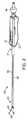
図1に示されるように、本発明の原理に従って構築されるシステム10は、システム制
御装置12と治療プローブ14の両方を含む。システム制御装置12は、処理および電源
ユニット16および表示画面18を含むことになる。制御装置12は、治療している医師
が情報を入力するための、キーボード、タッチ画面、制御パネル等の手段をさらに含むこ
とになる。処理および電源ユニット16は通常、無線周波、マイクロ波、蒸気、治療的プ
ラズマ、または治療エネルギーまたは他の治療薬を治療プローブ14に送達する回路もし
くは機構を含むことになる。有利なことに、システム制御装置12は、画面およびロジッ
クの両方を提供し、および別個の無線周波、マイクロ波、HEFU、液体注入、プラズマ
注入、蒸気、凍結療法または所望の治療を提供する他の供給源に接続するために、従来の
デスクトップまたはラップトップコンピュータを含むことができる。(Detailed Description of the Invention)
As shown in FIG. 1, a system 10 constructed in accordance with the principles of the present invention includes both a
治療プローブ14は、通常は、その近位端にハンドル22を有するシャフト20を含む
。針24および撮像アレイ26は、図2〜図4を参照して以下でより詳細に説明されるよ
うに、シャフト20の遠位端に提供される。図2〜図4に示す治療プローブ14は、20
07年5月15日に出願された、同時係属中の仮出願第60/938,140号(代理人
整理番号025676−001700US)、により詳細に記載されており、その完全な
開示は本明細書に参考として援用される。The
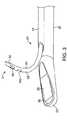
Co-pending
プローブ14は、概して、剛体または他の送達シャフト20、超音波撮像変換器26、
およびアーチファクト/特徴100をその遠位端51(図3)に持つ、音波を発生する湾
曲した針24を含む。図示されるように、アーチファクトは、角を切断した種類の逆反射
体である。ハンドル22は、シャフト20の近位端21に取り付けられている。シャフト
20の遠位端23は、図4に最良に示されるように、曲がったまたはたわんだ遠位先端を
有する。超音波撮像変換器26は、視野46(図4)の中で撮像する、平らな観察窓36
(図3)の中に配置される線形超音波アレイを含む。単一の直線の針24のみが図示され
るが、プローブは、アレイの中に複数の針を保持してもよく、および/または針は、直線
でも、または任意の他の構造を有してもよい。The
And includes a
(FIG. 3) includes a linear ultrasound array disposed within. Although only a single
針24は、無線周波組織焼灼用の固体先端導電性針である。他の場所でも述べたように
、他の形式のエネルギーの送達用であることができ、または物質送達または注射用の中空
針であることができる。例示的針24は、概して、細長い中空体48(図3に最良に示さ
れるように)とその遠位端に固体遠位先端50を含む、2ピース構造を含む。遠位先端5
0は、中空の管状体48にレーザ溶接されてもよい。固体先端50はまた、例えば接着剤
または機械的機構または嵌合等の代替手段によって取り付けられてもよい。中空管48は
、概して、20cm〜約45cmの範囲の長さを有することになる。いくつかの実施形態
では、中空管は、概して、0.5mm〜約2mmの範囲の厚み、および概して、1mm〜
約3mmの範囲の幅を有する楕円形の断面を有することになる。この扁平な楕円形の断面
は、存在時に、針24の展開または貫通時の外側偏向を阻止することを意図する。図3は
また、焼灼治療の前または最中の針14の治療効果を高めるように、薬物(例えば、電解
液、薬剤等)を注入するための、管状体48の遠位端内部の代表的なレーザ切断穴60を
図示する。注入穴60は、管状体48の一面に合わせられてもよく、概して、0.5mm
〜約2mmの範囲の長さおよび0.5mm〜約2mmの範囲の幅を有する。穴60は、1
つまたは複数の穴を含んでもよく、各々が異なる目的のために使用されてもよいというこ
とに留意されたい。
0 may be laser welded to the hollow
It will have an elliptical cross section with a width in the range of about 3 mm. This flat oval cross-section is intended to prevent, in the presence of it, outward deflection when the
Have a length in the range of ~ 2 mm and a width in the range of 0.5 mm to about 2 mm.
Note that one or more holes may be included and each may be used for a different purpose.
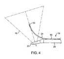
ハンドル24は、針ガイド44へのおよび針ガイド44からの針14の進入および格納
を可能にするための、長手方向に移動可能な滑動部72をさらに含む。超音波撮像変換器
26は随意に、シャフト20の軸路内部に交換可能に配置される撮像挿入物上にあっても
よい。密閉要素30は、近位端の挿入物の周りの十分な密閉を確実とするために、超音波
撮像変換器26とシャフトハンドル24との間に提供されてもよい。上記の記述は、説明
のみを目的としており、システム10の実際の形状、サイズ、または寸法を必ずしも反映
していないということが理解されよう。さらに、超音波アレイは、シャフトの中心線20
に平行であってもよく、または図4に示されるように、わずかに傾斜していてもよい。こ
れは以下のすべての描写に当てはまる。アレイは一般に、16〜128の要素、通常は、
64の要素を有する線形アレイである。アレイ12の長さ(アジマス)は、通常、約5m
m〜約20mmの範囲であり、普通は、約14mmである。アレイは、約1mm〜約8m
mの範囲、普通は、約2mmの深さ(高位)を有してもよい。一実施例では、超音波アレ
イは、約2MHz〜約15MHzの範囲、一般に、約5MHz〜約12MHz、通常は約
6.5MHzの中心周波数で超音波を送信する。The
Or may be slightly inclined as shown in FIG. This applies to all of the following descriptions. An array is typically 16 to 128 elements, usually
A linear array with 64 elements. The length of the array 12 (azimuth) is usually about 5 m.
m to about 20 mm, and usually about 14 mm. The array is about 1 mm to about 8 m
It may have a range of m, usually about 2 mm deep (high). In one example, the ultrasound array transmits ultrasound at a center frequency in the range of about 2 MHz to about 15 MHz, typically about 5 MHz to about 12 MHz, usually about 6.5 MHz.
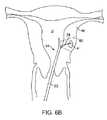
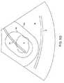
ここで図5を参照すると、子宮筋腫を治療するための、本発明の針位置決め方法を実施
する例示的手順が記載される。プローブ14が子宮内に位置決めされた後、治療している
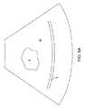
医師は、図6Aに示すように、筋腫Fを位置特定するために、子宮筋層Mを走査する。シ
ャフト20は、図8Aに示すもののように、変換器アレイ26の視野46がシステム12
の画面18上に視覚映像を提供することができるように操作される。いったん筋腫Fが位
置特定されると、医師は、図8Aに示すように、治療の影響を受ける漿膜S等の他の解剖
学的特徴についての映像を走査することができる。生成される映像は「実時間」であり、
視野46が子宮筋層の異なる部分上を走査することができるように、医師がシャフト20
を子宮Uの内部で動かすにつれて映像は変化するということが理解されるべきである。Referring now to FIG. 5, an exemplary procedure for implementing the needle positioning method of the present invention for treating uterine fibroids is described. After the
The
The physician can use the
It should be understood that the image changes as the is moved within the uterus U.
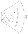
図5の手順における次のステップは、針ガイドのオーバーレイを筋腫と合わせることに
依存する。針ガイドは、図8Bに示すように、単純な一対の平行線70であってもよい。
平行線70は、通常、おそらく横方向への針の進入経路の制限を表すことになる。故に、
概して、標的筋腫Fを横切る線70を合わせることにより、図8Cに示すように、筋腫の
中央に向かって方向付けられることになる可能性は増大する。The next step in the procedure of FIG. 5 relies on aligning the needle guide overlay with the fibroid. The needle guide may be a simple pair of
The
In general, matching the
治療している医師は、針ガイドライン70の位置を、図8Cに示すように、これらが許
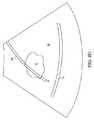
容できるように合わさるまで、筋腫Fと関連して視覚的に査定することを継続する。医師
は次に、図6Bに示すように、実際の針を組織内部に進入させ、実際の針の映像は図8D
に示される。針の実際の位置の映像が出現した後、映像上のカーソルを動かしてクリック
する、画面に触れる等によって、医師は予め選択された位置を針の上にマークする。その
ような実際の位置の「マーク」は、システムが投影される安全境界および投影される治療
範囲を算出するまたは再び算出することを可能にする。例えば、システムは、図8E上の
場所80に示すように、針の先端の近傍にマークされてもよい。The treating physician continues to visually assess the position of the
Shown in After an image of the actual position of the needle appears, the doctor marks the preselected position on the needle by moving the cursor on the image and clicking, touching the screen, or the like. Such “marks” of actual position allow the system to calculate or re-calculate the safe boundary and the projected treatment area to be projected. For example, the system may be marked near the tip of the needle, as shown at location 80 on FIG. 8E.
ここで図7を参照すると、単一針筋腫焼灼システムについての例示的安全境界90およ
び治療部位92について説明される。治療針24は、1cm〜3cmの範囲の、通常は、
2cmの長さlを有する、絶縁されていない治療部分96を有する。安全境界は、概して
、治療している電極部分96の露出した外部からの距離である、楕円形の線となる。距離
は、通常、1cm〜3cmの範囲であり、通常、約1.5cmである。露出した針部分9
6と治療部位境界92との間の距離は、通常は、安全距離の約半分であり、一般に、0.
5cm〜1.5cmの範囲であり、通常は約0.75cmである。概して、針24の遠位
先端からの距離ttと、安全境界および治療部位境界線は、先端のエネルギー密度の低下
のため、いくぶん短くなる。故に、先端と治療部位境界線との間の距離ttは、0.1c
m〜0.5cm、通常は、約0.25cmであってもよく、一方、先端と安全境界との間
の距離tsは、0.5cm〜1.5cmの範囲であり、通常は、約1cmとなる。Referring now to FIG. 7, an
It has an
6 and the
It is in the range of 5 cm to 1.5 cm, usually about 0.75 cm. In general, the distance tt from the distal tip of the
m to 0.5 cm, usually about 0.25 cm, while the distance ts between the tip and the safety boundary is in the range of 0.5 cm to 1.5 cm, usually about 1 cm. It becomes.
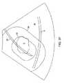
これらの所望のクリアランス距離に基づいて、システムは、図8Fに示すように、治療
および安全オーバーレイを針24の実際の映像上に投影する。医師は次に、漿膜S等の繊
細な組織構造が、投影される安全境界90外に留まるかどうかを視覚的に査定する。図8
Fに示すように、漿膜Sが安全境界90内にあるため、安全境界を越えて漿膜Sを移動さ
せるために、針24を再位置決めまたは再展開することが必要となる。ということに留意
されたい。筋腫Fについての治療境界線92の位置は、治療のためにはおそらく十分であ
るが、針は、安全性の考慮に基づいて展開される必要がある。Based on these desired clearance distances, the system projects the treatment and safety overlay onto the actual image of the
As shown at F, because the serosa S is within the
いったん針が再位置決めまたは再展開されると、図8Gに示すように、安全境界が漿膜
Sに侵入しない一方で、治療部位92が十分に筋腫Fを覆うように、医師は治療のために
システムを有効化することになる。通常、システムは、システムが針に電力を供給するこ
とを可能にする前に、針が正しく位置決めされたことを承認することを医師に要求するこ
とになる。いったんそれが完了すると、概して、本明細書に参考として援用される、先行
出願に記載されるように、医師は治療を開始することができる。Once the needle has been repositioned or redeployed, the physician can provide a system for treatment so that the
上記は本発明の好ましい実施形態の完全な説明であるが、種々の代替物、修正物および
均等物が使用されてもよい。したがって、上記の説明は、添付の請求項によって規定され
る本発明の範囲を限定するように受け取られるべきでない。While the above is a complete description of the preferred embodiment of the invention, various alternatives, modifications and equivalents may be used. Therefore, the above description should not be taken as limiting the scope of the invention which is defined by the appended claims.
Claims (1)
Translated fromJapaneseApplications Claiming Priority (2)
| Application Number | Priority Date | Filing Date | Title |
|---|---|---|---|
| US97961307P | 2007-10-12 | 2007-10-12 | |
| US60/979,613 | 2007-10-12 |
Related Parent Applications (1)
| Application Number | Title | Priority Date | Filing Date |
|---|---|---|---|
| JP2015186299ADivisionJP6473404B2 (en) | 2007-10-12 | 2015-09-24 | Method and system for controlled deployment of a needle in tissue |
Related Child Applications (1)
| Application Number | Title | Priority Date | Filing Date |
|---|---|---|---|
| JP2019003560ADivisionJP2019072535A (en) | 2007-10-12 | 2019-01-11 | Methods and systems for controlled deployment of needles in tissue |
Publications (3)
| Publication Number | Publication Date |
|---|---|
| JP2018047295Atrue JP2018047295A (en) | 2018-03-29 |
| JP2018047295A5 JP2018047295A5 (en) | 2020-01-16 |
| JP6674432B2 JP6674432B2 (en) | 2020-04-01 |
Family
ID=40534934
Family Applications (7)
| Application Number | Title | Priority Date | Filing Date |
|---|---|---|---|
| JP2010529053AActiveJP5964010B2 (en) | 2007-10-12 | 2008-10-09 | Method and system for controlled deployment of a needle in tissue |
| JP2013233728AWithdrawnJP2014050748A (en) | 2007-10-12 | 2013-11-12 | Improved method and system for controlled expansion of needle in bio-tissue |
| JP2015186299AActiveJP6473404B2 (en) | 2007-10-12 | 2015-09-24 | Method and system for controlled deployment of a needle in tissue |
| JP2017227040AActiveJP6674432B2 (en) | 2007-10-12 | 2017-11-27 | Methods and systems for controlled deployment of needles in tissue |
| JP2019003560AWithdrawnJP2019072535A (en) | 2007-10-12 | 2019-01-11 | Methods and systems for controlled deployment of needles in tissue |
| JP2021204109AWithdrawnJP2022033982A (en) | 2007-10-12 | 2021-12-16 | Methods and systems for controlled deployment of needles in tissue |
| JP2024000619APendingJP2024024069A (en) | 2007-10-12 | 2024-01-05 | Method and system for controlled deployment of needles within tissue |
Family Applications Before (3)
| Application Number | Title | Priority Date | Filing Date |
|---|---|---|---|
| JP2010529053AActiveJP5964010B2 (en) | 2007-10-12 | 2008-10-09 | Method and system for controlled deployment of a needle in tissue |
| JP2013233728AWithdrawnJP2014050748A (en) | 2007-10-12 | 2013-11-12 | Improved method and system for controlled expansion of needle in bio-tissue |
| JP2015186299AActiveJP6473404B2 (en) | 2007-10-12 | 2015-09-24 | Method and system for controlled deployment of a needle in tissue |
Family Applications After (3)
| Application Number | Title | Priority Date | Filing Date |
|---|---|---|---|
| JP2019003560AWithdrawnJP2019072535A (en) | 2007-10-12 | 2019-01-11 | Methods and systems for controlled deployment of needles in tissue |
| JP2021204109AWithdrawnJP2022033982A (en) | 2007-10-12 | 2021-12-16 | Methods and systems for controlled deployment of needles in tissue |
| JP2024000619APendingJP2024024069A (en) | 2007-10-12 | 2024-01-05 | Method and system for controlled deployment of needles within tissue |
Country Status (7)
| Country | Link |
|---|---|
| US (11) | US8088072B2 (en) |
| EP (3) | EP3420916B1 (en) |
| JP (7) | JP5964010B2 (en) |
| AU (1) | AU2008310843B2 (en) |
| CA (1) | CA2702353C (en) |
| ES (2) | ES2685448T3 (en) |
| WO (1) | WO2009049082A1 (en) |
Families Citing this family (79)
| Publication number | Priority date | Publication date | Assignee | Title |
|---|---|---|---|---|
| US7918795B2 (en) | 2005-02-02 | 2011-04-05 | Gynesonics, Inc. | Method and device for uterine fibroid treatment |
| US8080009B2 (en) | 2005-07-01 | 2011-12-20 | Halt Medical Inc. | Radio frequency ablation device for the destruction of tissue masses |
| US8512330B2 (en)* | 2005-07-01 | 2013-08-20 | Halt Medical Inc. | Ablation method |
| US8784336B2 (en) | 2005-08-24 | 2014-07-22 | C. R. Bard, Inc. | Stylet apparatuses and methods of manufacture |
| US10058342B2 (en) | 2006-01-12 | 2018-08-28 | Gynesonics, Inc. | Devices and methods for treatment of tissue |
| US7874986B2 (en)* | 2006-04-20 | 2011-01-25 | Gynesonics, Inc. | Methods and devices for visualization and ablation of tissue |
| US11259825B2 (en) | 2006-01-12 | 2022-03-01 | Gynesonics, Inc. | Devices and methods for treatment of tissue |
| US8388546B2 (en) | 2006-10-23 | 2013-03-05 | Bard Access Systems, Inc. | Method of locating the tip of a central venous catheter |
| US7794407B2 (en) | 2006-10-23 | 2010-09-14 | Bard Access Systems, Inc. | Method of locating the tip of a central venous catheter |
| US8088072B2 (en) | 2007-10-12 | 2012-01-03 | Gynesonics, Inc. | Methods and systems for controlled deployment of needles in tissue |
| US10751509B2 (en) | 2007-11-26 | 2020-08-25 | C. R. Bard, Inc. | Iconic representations for guidance of an indwelling medical device |
| US9649048B2 (en) | 2007-11-26 | 2017-05-16 | C. R. Bard, Inc. | Systems and methods for breaching a sterile field for intravascular placement of a catheter |
| US8781555B2 (en) | 2007-11-26 | 2014-07-15 | C. R. Bard, Inc. | System for placement of a catheter including a signal-generating stylet |
| US9636031B2 (en) | 2007-11-26 | 2017-05-02 | C.R. Bard, Inc. | Stylets for use with apparatus for intravascular placement of a catheter |
| ES2465915T3 (en) | 2007-11-26 | 2014-06-09 | C.R. Bard, Inc. | Integrated system for intravascular catheter placement |
| US9521961B2 (en) | 2007-11-26 | 2016-12-20 | C. R. Bard, Inc. | Systems and methods for guiding a medical instrument |
| US10524691B2 (en) | 2007-11-26 | 2020-01-07 | C. R. Bard, Inc. | Needle assembly including an aligned magnetic element |
| US10449330B2 (en) | 2007-11-26 | 2019-10-22 | C. R. Bard, Inc. | Magnetic element-equipped needle assemblies |
| US8849382B2 (en) | 2007-11-26 | 2014-09-30 | C. R. Bard, Inc. | Apparatus and display methods relating to intravascular placement of a catheter |
| WO2009112262A2 (en)* | 2008-03-12 | 2009-09-17 | Afreeze Gmbh | Handle for an ablation device |
| US9901714B2 (en) | 2008-08-22 | 2018-02-27 | C. R. Bard, Inc. | Catheter assembly including ECG sensor and magnetic assemblies |
| US9700365B2 (en) | 2008-10-06 | 2017-07-11 | Santa Anna Tech Llc | Method and apparatus for the ablation of gastrointestinal tissue |
| US10064697B2 (en)* | 2008-10-06 | 2018-09-04 | Santa Anna Tech Llc | Vapor based ablation system for treating various indications |
| US8437833B2 (en) | 2008-10-07 | 2013-05-07 | Bard Access Systems, Inc. | Percutaneous magnetic gastrostomy |
| US8632534B2 (en) | 2009-04-03 | 2014-01-21 | Angiodynamics, Inc. | Irreversible electroporation (IRE) for congestive obstructive pulmonary disease (COPD) |
| US10039527B2 (en) | 2009-05-20 | 2018-08-07 | Analogic Canada Corporation | Ultrasound systems incorporating spatial position sensors and associated methods |
| US8556815B2 (en) | 2009-05-20 | 2013-10-15 | Laurent Pelissier | Freehand ultrasound imaging systems and methods for guiding fine elongate instruments |
| WO2010138919A2 (en) | 2009-05-28 | 2010-12-02 | Angiodynamics, Inc. | System and method for synchronizing energy delivery to the cardiac rhythm |
| JP5795576B2 (en) | 2009-06-12 | 2015-10-14 | バード・アクセス・システムズ,インコーポレーテッド | Method of operating a computer-based medical device that uses an electrocardiogram (ECG) signal to position an intravascular device in or near the heart |
| US9532724B2 (en) | 2009-06-12 | 2017-01-03 | Bard Access Systems, Inc. | Apparatus and method for catheter navigation using endovascular energy mapping |
| US9895189B2 (en) | 2009-06-19 | 2018-02-20 | Angiodynamics, Inc. | Methods of sterilization and treating infection using irreversible electroporation |
| EP2464407A4 (en) | 2009-08-10 | 2014-04-02 | Bard Access Systems Inc | Devices and methods for endovascular electrography |
| EP3556308B1 (en) | 2009-11-05 | 2023-12-20 | Stratus Medical, LLC | Systems for spinal radio frequency neurotomy |
| US9486162B2 (en) | 2010-01-08 | 2016-11-08 | Ultrasonix Medical Corporation | Spatial needle guidance system and associated methods |
| WO2011097312A1 (en) | 2010-02-02 | 2011-08-11 | C.R. Bard, Inc. | Apparatus and method for catheter navigation and tip location |
| KR101632429B1 (en) | 2010-05-21 | 2016-06-21 | 님버스 컨셉츠, 엘엘씨 | Systems and methods for tissue ablation |
| EP2912999B1 (en) | 2010-05-28 | 2022-06-29 | C. R. Bard, Inc. | Apparatus for use with needle insertion guidance system |
| EP4122385A1 (en) | 2010-05-28 | 2023-01-25 | C. R. Bard, Inc. | Insertion guidance system for needles and medical components |
| BR112013002431B1 (en) | 2010-08-20 | 2021-06-29 | C.R. Bard, Inc | SYSTEM FOR RECONFIRMING THE POSITION OF A CATHETER INSIDE A PATIENT |
| EP2627274B1 (en) | 2010-10-13 | 2022-12-14 | AngioDynamics, Inc. | System for electrically ablating tissue of a patient |
| US8801693B2 (en) | 2010-10-29 | 2014-08-12 | C. R. Bard, Inc. | Bioimpedance-assisted placement of a medical device |
| JP6000569B2 (en)* | 2011-04-01 | 2016-09-28 | 東芝メディカルシステムズ株式会社 | Ultrasonic diagnostic apparatus and control program |
| US8545409B2 (en)* | 2011-04-14 | 2013-10-01 | St. Jude Medical, Inc. | Arrangement and interface for RF ablation system with acoustic feedback |
| US20140051989A1 (en)* | 2011-04-19 | 2014-02-20 | Drexel University | Devices adapted for ultrasound location in patients and method of use |
| RU2609203C2 (en) | 2011-07-06 | 2017-01-30 | Си.Ар. Бард, Инк. | Determination and calibration of needle length for needle guidance system |
| US9078665B2 (en) | 2011-09-28 | 2015-07-14 | Angiodynamics, Inc. | Multiple treatment zone ablation probe |
| KR101828453B1 (en)* | 2011-12-09 | 2018-02-13 | 삼성전자주식회사 | Medical robotic system and control method for thereof |
| US9295449B2 (en) | 2012-01-23 | 2016-03-29 | Ultrasonix Medical Corporation | Landmarks for ultrasound imaging |
| US9414881B2 (en) | 2012-02-08 | 2016-08-16 | Angiodynamics, Inc. | System and method for increasing a target zone for electrical ablation |
| US9113825B2 (en)* | 2012-07-10 | 2015-08-25 | Fujifilm Sonosite, Inc. | Ultrasonic probe and aligned needle guide system |
| US8992427B2 (en)* | 2012-09-07 | 2015-03-31 | Gynesonics, Inc. | Methods and systems for controlled deployment of needle structures in tissue |
| WO2015058096A1 (en) | 2013-10-18 | 2015-04-23 | Ziva Medical, Inc. | Methods and systems for the treatment of polycystic ovary syndrome |
| US10307135B2 (en)* | 2013-11-20 | 2019-06-04 | Advanced Access Solutions, Inc. | Intravascular ultrasound needle guide |
| WO2015120256A2 (en) | 2014-02-06 | 2015-08-13 | C.R. Bard, Inc. | Systems and methods for guidance and placement of an intravascular device |
| JP6604977B2 (en)* | 2014-07-02 | 2019-11-13 | コヴィディエン リミテッド パートナーシップ | System that provides distance and orientation feedback during 3D navigation |
| US12114911B2 (en) | 2014-08-28 | 2024-10-15 | Angiodynamics, Inc. | System and method for ablating a tissue site by electroporation with real-time pulse monitoring |
| US10973584B2 (en) | 2015-01-19 | 2021-04-13 | Bard Access Systems, Inc. | Device and method for vascular access |
| ES2964948T3 (en) | 2015-03-31 | 2024-04-10 | May Health Us Inc | Methods and systems for the manipulation of ovarian tissues |
| JP6843073B2 (en)* | 2015-05-18 | 2021-03-17 | コーニンクレッカ フィリップス エヌ ヴェKoninklijke Philips N.V. | Accuracy feedback during procedure for image-guided biopsy |
| WO2016210325A1 (en) | 2015-06-26 | 2016-12-29 | C.R. Bard, Inc. | Connector interface for ecg-based catheter positioning system |
| US11000207B2 (en) | 2016-01-29 | 2021-05-11 | C. R. Bard, Inc. | Multiple coil system for tracking a medical device |
| US12364537B2 (en) | 2016-05-02 | 2025-07-22 | Santa Anna Tech Llc | Catheter with a double balloon structure to generate and apply a heated ablative zone to tissue |
| CN115715689B (en)* | 2016-11-11 | 2025-01-17 | 杰尼索尼克斯公司 | Tissue controlled treatment and dynamic interaction and comparison with tissue and/or treatment data |
| KR20190086485A (en)* | 2016-11-14 | 2019-07-22 | 지네소닉스, 인크. | Methods and systems for real-time planning and monitoring of ablation needle deployment within an organization |
| US10905492B2 (en) | 2016-11-17 | 2021-02-02 | Angiodynamics, Inc. | Techniques for irreversible electroporation using a single-pole tine-style internal device communicating with an external surface electrode |
| JP2020518385A (en) | 2017-05-04 | 2020-06-25 | ガイネソニックス, インコーポレイテッド | A method for monitoring ablation progression using Doppler ultrasound |
| CN111801056B (en)* | 2017-12-21 | 2024-06-28 | 爱惜康有限责任公司 | Surgical instrument with display including image layer |
| US11129680B2 (en)* | 2017-12-21 | 2021-09-28 | Cilag Gmbh International | Surgical instrument comprising a projector |
| US10912542B2 (en)* | 2018-03-14 | 2021-02-09 | Spiration, Inc. | Catheter assembly with offset device for tissue sampling |
| EP3773232A1 (en)* | 2018-04-06 | 2021-02-17 | Medtronic, Inc. | Image-based navigation system and method of using same |
| CA3101095A1 (en) | 2018-05-21 | 2019-11-28 | Gynesonics, Inc. | Methods and systems for in situ exchange |
| EP3801324B1 (en) | 2018-06-01 | 2025-05-28 | Aqua Medical, Inc. | Vapor generation and delivery systems |
| US10992079B2 (en) | 2018-10-16 | 2021-04-27 | Bard Access Systems, Inc. | Safety-equipped connection systems and methods thereof for establishing electrical connections |
| KR102747176B1 (en)* | 2018-12-11 | 2024-12-27 | 삼성메디슨 주식회사 | Ultrasound imaging apparatus, method for controlling the same, and computer program product |
| US11564736B2 (en) | 2019-01-25 | 2023-01-31 | May Health Sas | Systems and methods for applying energy to ovarian tissue |
| US20210204907A1 (en) | 2020-01-07 | 2021-07-08 | Covidien Lp | Devices, systems, and methods for trans-vaginal, ultrasound-guided hysteroscopic surgical procedures |
| JP2023527614A (en)* | 2020-03-30 | 2023-06-30 | エンプレス メディカル,インク. | Prediction of curved penetration paths for surgical devices |
| NL2026208B1 (en)* | 2020-08-04 | 2022-04-08 | Stichting Het Nederlands Kanker Inst Antoni Van Leeuwenhoek Ziekenhuis | Surgical forceps and stapler |
| WO2024014906A1 (en)* | 2022-07-13 | 2024-01-18 | 주식회사 로엔서지컬 | System and method for providing guidance for calculus removal |
Citations (4)
| Publication number | Priority date | Publication date | Assignee | Title |
|---|---|---|---|---|
| JPH11508790A (en)* | 1995-06-30 | 1999-08-03 | ボストン・サイエンティフィック・コーポレイション | Ultrasound projection catheter with cutting element |
| JP2001340350A (en)* | 2000-03-28 | 2001-12-11 | Aloka Co Ltd | Medical system |
| JP2006513831A (en)* | 2003-01-16 | 2006-04-27 | シャーロット‐メクレンバーグ・ホスピタル・オーソリティ,ドゥーイング・ビジネス・アズ・キャロライナズ・メディカル・センター | Echogenic needle and related methods for transvaginal ultrasound for the reduction of uterine fibroma |
| JP2007215672A (en)* | 2006-02-15 | 2007-08-30 | Toshiba Corp | Ultrasonic diagnostic apparatus and treatment support apparatus |
Family Cites Families (256)
| Publication number | Priority date | Publication date | Assignee | Title |
|---|---|---|---|---|
| US4289132A (en) | 1979-06-25 | 1981-09-15 | Rieman Robert D | Surgical instrument and method of using the same |
| US5370675A (en) | 1992-08-12 | 1994-12-06 | Vidamed, Inc. | Medical probe device and method |
| US4671292A (en)* | 1985-04-30 | 1987-06-09 | Dymax Corporation | Concentric biopsy probe |
| US4802487A (en) | 1987-03-26 | 1989-02-07 | Washington Research Foundation | Endoscopically deliverable ultrasound imaging system |
| US5269301A (en)* | 1987-10-06 | 1993-12-14 | Leonard Bloom | Multimode system for monitoring and treating a malfunctioning heart |
| US5372587A (en) | 1989-01-09 | 1994-12-13 | Pilot Cariovascular Systems, Inc. | Steerable medical device |
| US4936281A (en) | 1989-04-13 | 1990-06-26 | Everest Medical Corporation | Ultrasonically enhanced RF ablation catheter |
| US5316000A (en) | 1991-03-05 | 1994-05-31 | Technomed International (Societe Anonyme) | Use of at least one composite piezoelectric transducer in the manufacture of an ultrasonic therapy apparatus for applying therapy, in a body zone, in particular to concretions, to tissue, or to bones, of a living being and method of ultrasonic therapy |
| US6485413B1 (en) | 1991-04-29 | 2002-11-26 | The General Hospital Corporation | Methods and apparatus for forward-directed optical scanning instruments |
| US7549424B2 (en) | 1991-10-18 | 2009-06-23 | Pro Surg, Inc. | Method and apparatus for tissue treatment with laser and electromagnetic radiation |
| US6461296B1 (en) | 1998-06-26 | 2002-10-08 | 2000 Injectx, Inc. | Method and apparatus for delivery of genes, enzymes and biological agents to tissue cells |
| US6730081B1 (en) | 1991-10-18 | 2004-05-04 | Ashvin H. Desai | Endoscopic surgical instrument |
| US6770071B2 (en) | 1995-06-07 | 2004-08-03 | Arthrocare Corporation | Bladed electrosurgical probe |
| US6024733A (en) | 1995-06-07 | 2000-02-15 | Arthrocare Corporation | System and method for epidermal tissue ablation |
| US5470308A (en) | 1992-08-12 | 1995-11-28 | Vidamed, Inc. | Medical probe with biopsy stylet |
| US5364408A (en) | 1992-09-04 | 1994-11-15 | Laurus Medical Corporation | Endoscopic suture system |
| US6832996B2 (en) | 1995-06-07 | 2004-12-21 | Arthrocare Corporation | Electrosurgical systems and methods for treating tissue |
| US5860974A (en) | 1993-07-01 | 1999-01-19 | Boston Scientific Corporation | Heart ablation catheter with expandable electrode and method of coupling energy to an electrode on a catheter shaft |
| US5456689A (en) | 1993-10-13 | 1995-10-10 | Arnold J. Kresch | Method and device for tissue resection |
| US5599346A (en) | 1993-11-08 | 1997-02-04 | Zomed International, Inc. | RF treatment system |
| US6569159B1 (en) | 1993-11-08 | 2003-05-27 | Rita Medical Systems, Inc. | Cell necrosis apparatus |
| US6241725B1 (en)* | 1993-12-15 | 2001-06-05 | Sherwood Services Ag | High frequency thermal ablation of cancerous tumors and functional targets with image data assistance |
| US5471988A (en) | 1993-12-24 | 1995-12-05 | Olympus Optical Co., Ltd. | Ultrasonic diagnosis and therapy system in which focusing point of therapeutic ultrasonic wave is locked at predetermined position within observation ultrasonic scanning range |
| DE4443947B4 (en) | 1994-01-14 | 2005-09-22 | Siemens Ag | endoscope |
| US5873828A (en) | 1994-02-18 | 1999-02-23 | Olympus Optical Co., Ltd. | Ultrasonic diagnosis and treatment system |
| US5517989A (en) | 1994-04-01 | 1996-05-21 | Cardiometrics, Inc. | Guidewire assembly |
| US5492126A (en) | 1994-05-02 | 1996-02-20 | Focal Surgery | Probe for medical imaging and therapy using ultrasound |
| JP3419884B2 (en)* | 1994-05-11 | 2003-06-23 | オリンパス光学工業株式会社 | Control system |
| US6002968A (en) | 1994-06-24 | 1999-12-14 | Vidacare, Inc. | Uterine treatment apparatus |
| US6405732B1 (en) | 1994-06-24 | 2002-06-18 | Curon Medical, Inc. | Method to treat gastric reflux via the detection and ablation of gastro-esophageal nerves and receptors |
| US6032673A (en) | 1994-10-13 | 2000-03-07 | Femrx, Inc. | Methods and devices for tissue removal |
| US6575969B1 (en)* | 1995-05-04 | 2003-06-10 | Sherwood Services Ag | Cool-tip radiofrequency thermosurgery electrode system for tumor ablation |
| US6837887B2 (en) | 1995-06-07 | 2005-01-04 | Arthrocare Corporation | Articulated electrosurgical probe and methods |
| US5979452A (en) | 1995-06-07 | 1999-11-09 | General Surgical Innovations, Inc. | Endoscopic linton procedure using balloon dissectors and retractors |
| US5964740A (en) | 1996-07-09 | 1999-10-12 | Asahi Kogaku Kogyo Kabushiki Kaisha | Treatment accessory for an endoscope |
| US6632193B1 (en) | 1995-06-07 | 2003-10-14 | Arthrocare Corporation | Systems and methods for electrosurgical tissue treatment |
| US6837888B2 (en) | 1995-06-07 | 2005-01-04 | Arthrocare Corporation | Electrosurgical probe with movable return electrode and methods related thereto |
| US5590658A (en) | 1995-06-29 | 1997-01-07 | Teratech Corporation | Portable ultrasound imaging system |
| US5964709A (en) | 1995-06-29 | 1999-10-12 | Teratech Corporation | Portable ultrasound imaging system |
| KR19990029038A (en) | 1995-07-16 | 1999-04-15 | 요아브 빨띠에리 | Free aiming of needle ceramic |
| US6256529B1 (en)* | 1995-07-26 | 2001-07-03 | Burdette Medical Systems, Inc. | Virtual reality 3D visualization for surgical procedures |
| US6080150A (en) | 1995-08-15 | 2000-06-27 | Rita Medical Systems, Inc. | Cell necrosis apparatus |
| US6375615B1 (en) | 1995-10-13 | 2002-04-23 | Transvascular, Inc. | Tissue penetrating catheters having integral imaging transducers and their methods of use |
| US5979453A (en) | 1995-11-09 | 1999-11-09 | Femrx, Inc. | Needle myolysis system for uterine fibriods |
| US5780435A (en) | 1995-12-15 | 1998-07-14 | Praecis Pharmaceuticals Incorporated | Methods for treating prostate cancer with LHRH-R antagonists |
| US5863294A (en) | 1996-01-26 | 1999-01-26 | Femrx, Inc. | Folded-end surgical tubular cutter and method for fabrication |
| US6203524B1 (en) | 1997-02-10 | 2001-03-20 | Emx, Inc. | Surgical and pharmaceutical site access guide and methods |
| US5769880A (en) | 1996-04-12 | 1998-06-23 | Novacept | Moisture transport system for contact electrocoagulation |
| US6813520B2 (en) | 1996-04-12 | 2004-11-02 | Novacept | Method for ablating and/or coagulating tissue using moisture transport |
| US6419673B1 (en) | 1996-05-06 | 2002-07-16 | Stuart Edwards | Ablation of rectal and other internal body structures |
| US6077257A (en) | 1996-05-06 | 2000-06-20 | Vidacare, Inc. | Ablation of rectal and other internal body structures |
| US5649911A (en) | 1996-05-17 | 1997-07-22 | Indiana University Foundation | Intravenous catheter and delivery system |
| US5957941A (en) | 1996-09-27 | 1999-09-28 | Boston Scientific Corporation | Catheter system and drive assembly thereof |
| EP0944382A1 (en) | 1996-09-30 | 1999-09-29 | Brigham & Women's Hospital | Methods and compounds for treatment of abnormal uterine bleeding |
| US6719755B2 (en) | 1996-10-22 | 2004-04-13 | Epicor Medical, Inc. | Methods and devices for ablation |
| US6805128B1 (en) | 1996-10-22 | 2004-10-19 | Epicor Medical, Inc. | Apparatus and method for ablating tissue |
| US5730752A (en) | 1996-10-29 | 1998-03-24 | Femrx, Inc. | Tubular surgical cutters having aspiration flow control ports |
| US5741287A (en) | 1996-11-01 | 1998-04-21 | Femrx, Inc. | Surgical tubular cutter having a tapering cutting chamber |
| US5910104A (en)* | 1996-12-26 | 1999-06-08 | Cryogen, Inc. | Cryosurgical probe with disposable sheath |
| US6270494B1 (en)* | 1996-12-26 | 2001-08-07 | Cryogen, Inc. | Stretchable cryoprobe sheath |
| US5931787A (en) | 1997-02-11 | 1999-08-03 | Tetrad Corporation | Sheath and methods of ultrasonic guidance for biopsy and catheter insertion |
| US6314310B1 (en) | 1997-02-14 | 2001-11-06 | Biosense, Inc. | X-ray guided surgical location system with extended mapping volume |
| US5906615A (en) | 1997-03-31 | 1999-05-25 | Femrx, Inc. | Serpentine ablation/coagulation electrode |
| US5984942A (en) | 1997-04-02 | 1999-11-16 | Femrx, Inc. | Methods and systems for reducing tissue adhesion |
| US5873877A (en) | 1997-04-11 | 1999-02-23 | Vidamed, Inc. | Medical probe device with transparent distal extremity |
| US5876340A (en) | 1997-04-17 | 1999-03-02 | Irvine Biomedical, Inc. | Ablation apparatus with ultrasonic imaging capabilities |
| US5891137A (en) | 1997-05-21 | 1999-04-06 | Irvine Biomedical, Inc. | Catheter system having a tip with fixation means |
| US5876399A (en) | 1997-05-28 | 1999-03-02 | Irvine Biomedical, Inc. | Catheter system and methods thereof |
| US5921926A (en) | 1997-07-28 | 1999-07-13 | University Of Central Florida | Three dimensional optical imaging colposcopy |
| US6039748A (en) | 1997-08-05 | 2000-03-21 | Femrx, Inc. | Disposable laparoscopic morcellator |
| US5916198A (en) | 1997-08-05 | 1999-06-29 | Femrx, Inc. | Non-binding surgical valve |
| EP1014858A4 (en) | 1997-08-19 | 2005-07-13 | John D Mendlein | Ultrasonic transmission films and devices, particularly for hygienic transducer surfaces |
| US6055449A (en) | 1997-09-22 | 2000-04-25 | Siemens Corporate Research, Inc. | Method for localization of a biopsy needle or similar surgical tool in a radiographic image |
| JP2001517475A (en) | 1997-09-22 | 2001-10-09 | エシコン・インコーポレイテッド | Cryosurgery system and method |
| US6238389B1 (en) | 1997-09-30 | 2001-05-29 | Boston Scientific Corporation | Deflectable interstitial ablation device |
| US6171249B1 (en) | 1997-10-14 | 2001-01-09 | Circon Corporation | Ultrasound guided therapeutic and diagnostic device |
| US6325758B1 (en)* | 1997-10-27 | 2001-12-04 | Nomos Corporation | Method and apparatus for target position verification |
| US6007499A (en) | 1997-10-31 | 1999-12-28 | University Of Washington | Method and apparatus for medical procedures using high-intensity focused ultrasound |
| IL122336A0 (en)* | 1997-11-27 | 1998-04-05 | Ultra Guide Ltd | System and method for guiding the movements of a device to a target particularly for medical applications |
| US6280441B1 (en) | 1997-12-15 | 2001-08-28 | Sherwood Services Ag | Apparatus and method for RF lesioning |
| IL122839A0 (en)* | 1997-12-31 | 1998-08-16 | Ultra Guide Ltd | Calibration method and apparatus for calibrating position sensors on scanning transducers |
| US6146380A (en) | 1998-01-09 | 2000-11-14 | Radionics, Inc. | Bent tip electrical surgical probe |
| AU2114299A (en) | 1998-01-14 | 1999-08-02 | Conway-Stuart Medical, Inc. | Electrosurgical device for sphincter treatment |
| CN1058905C (en) | 1998-01-25 | 2000-11-29 | 重庆海扶(Hifu)技术有限公司 | High-intensity focus supersonic tumor scanning therapy system |
| US6059766A (en) | 1998-02-27 | 2000-05-09 | Micro Therapeutics, Inc. | Gynecologic embolotherapy methods |
| JP4125814B2 (en) | 1998-03-04 | 2008-07-30 | Hoya株式会社 | Ultrasound endoscope |
| JPH11276422A (en)* | 1998-03-31 | 1999-10-12 | Fuji Photo Optical Co Ltd | Ultrasonic endoscope |
| US6311084B1 (en)* | 1998-05-04 | 2001-10-30 | Robert A. Cormack | Radiation seed implant method and apparatus |
| US6635055B1 (en) | 1998-05-06 | 2003-10-21 | Microsulis Plc | Microwave applicator for endometrial ablation |
| US6508815B1 (en) | 1998-05-08 | 2003-01-21 | Novacept | Radio-frequency generator for powering an ablation device |
| US20050255039A1 (en) | 1998-06-26 | 2005-11-17 | Pro Surg, Inc., A California Corporation | Gel injection treatment of breast, fibroids & endometrial ablation |
| AU4842999A (en) | 1998-06-30 | 2000-01-17 | Arthrocare Corporation | Systems and methods for electrosurgical ablation of viable body structures |
| US6296639B1 (en) | 1999-02-12 | 2001-10-02 | Novacept | Apparatuses and methods for interstitial tissue removal |
| US7276063B2 (en) | 1998-08-11 | 2007-10-02 | Arthrocare Corporation | Instrument for electrosurgical tissue treatment |
| US7435247B2 (en) | 1998-08-11 | 2008-10-14 | Arthrocare Corporation | Systems and methods for electrosurgical tissue treatment |
| US6425867B1 (en) | 1998-09-18 | 2002-07-30 | University Of Washington | Noise-free real time ultrasonic imaging of a treatment site undergoing high intensity focused ultrasound therapy |
| US7686763B2 (en) | 1998-09-18 | 2010-03-30 | University Of Washington | Use of contrast agents to increase the effectiveness of high intensity focused ultrasound therapy |
| US6190383B1 (en) | 1998-10-21 | 2001-02-20 | Sherwood Services Ag | Rotatable electrode device |
| AU1727400A (en) | 1998-11-16 | 2000-06-05 | United States Surgical Corporation | Apparatus for thermal treatment of tissue |
| US6507747B1 (en) | 1998-12-02 | 2003-01-14 | Board Of Regents, The University Of Texas System | Method and apparatus for concomitant structural and biochemical characterization of tissue |
| US6254601B1 (en) | 1998-12-08 | 2001-07-03 | Hysterx, Inc. | Methods for occlusion of the uterine arteries |
| ES2228165T3 (en) | 1998-12-09 | 2005-04-01 | Cook Incorporated | HOLLOW NEEDLE, CURVED, SUPERELASTIC, FOR MEDICAL USE. |
| US6146378A (en) | 1999-03-19 | 2000-11-14 | Endocare, Inc. | Placement guide for ablation devices |
| AU3985400A (en)* | 1999-04-15 | 2000-11-02 | Ultra-Guide Ltd. | Apparatus and method for detecting the bending of medical invasive tools in medical interventions |
| US6463331B1 (en) | 1999-04-19 | 2002-10-08 | Novasys Medical, Inc. | Application of energy and substances in the treatment of uro-genital disorders |
| US6692490B1 (en) | 1999-05-18 | 2004-02-17 | Novasys Medical, Inc. | Treatment of urinary incontinence and other disorders by application of energy and drugs |
| US6139544A (en)* | 1999-05-26 | 2000-10-31 | Endocare, Inc. | Computer guided cryosurgery |
| EP1207788A4 (en) | 1999-07-19 | 2009-12-09 | St Jude Medical Atrial Fibrill | Apparatus and method for ablating tissue |
| ITMI991608A1 (en) | 1999-07-21 | 2001-01-21 | Thermo Med 2000 Kft | ELECTROSURGICAL PROBE FOR TREATMENT OF TUMORS BY RADIOFREQUENCY |
| US7520856B2 (en)* | 1999-09-17 | 2009-04-21 | University Of Washington | Image guided high intensity focused ultrasound device for therapy in obstetrics and gynecology |
| US20030032896A1 (en) | 2000-09-25 | 2003-02-13 | Vance Products, Inc., D/B/A/ Cook Urological, Inc. | Microvolume embryo transfer system |
| US20020077550A1 (en) | 1999-10-05 | 2002-06-20 | Rabiner Robert A. | Apparatus and method for treating gynecological diseases using an ultrasonic medical device operating in a transverse mode |
| JP4216501B2 (en) | 1999-11-10 | 2009-01-28 | サイティック・サージカル・プロダクツ | Device for detecting perforations in body cavities |
| US6626855B1 (en) | 1999-11-26 | 2003-09-30 | Therus Corpoation | Controlled high efficiency lesion formation using high intensity ultrasound |
| US6506156B1 (en) | 2000-01-19 | 2003-01-14 | Vascular Control Systems, Inc | Echogenic coating |
| US6158250A (en) | 2000-02-14 | 2000-12-12 | Novacept | Flat-bed knitting machine and method of knitting |
| US6579298B1 (en) | 2000-02-29 | 2003-06-17 | Scimed Life Systems, Inc. | Method and apparatus for treating vein graft lesions |
| US6379348B1 (en) | 2000-03-15 | 2002-04-30 | Gary M. Onik | Combined electrosurgical-cryosurgical instrument |
| US6419648B1 (en) | 2000-04-21 | 2002-07-16 | Insightec-Txsonics Ltd. | Systems and methods for reducing secondary hot spots in a phased array focused ultrasound system |
| US6543272B1 (en) | 2000-04-21 | 2003-04-08 | Insightec-Txsonics Ltd. | Systems and methods for testing and calibrating a focused ultrasound transducer array |
| US6550482B1 (en) | 2000-04-21 | 2003-04-22 | Vascular Control Systems, Inc. | Methods for non-permanent occlusion of a uterine artery |
| US6613004B1 (en) | 2000-04-21 | 2003-09-02 | Insightec-Txsonics, Ltd. | Systems and methods for creating longer necrosed volumes using a phased array focused ultrasound system |
| ATE378009T1 (en) | 2000-05-16 | 2007-11-15 | Atrionix Inc | DEVICE WITH AN ULTRASONIC TRANSDUCER ON A FEEDER |
| US6654202B2 (en) | 2000-06-20 | 2003-11-25 | Seagate Technology Llc | Disc drive with layered write coil |
| US6506171B1 (en) | 2000-07-27 | 2003-01-14 | Insightec-Txsonics, Ltd | System and methods for controlling distribution of acoustic energy around a focal point using a focused ultrasound system |
| WO2002009571A2 (en)* | 2000-07-31 | 2002-02-07 | Galil Medical Ltd. | Planning and facilitation systems and methods for cryosurgery |
| US7678106B2 (en) | 2000-08-09 | 2010-03-16 | Halt Medical, Inc. | Gynecological ablation procedure and system |
| US6840935B2 (en) | 2000-08-09 | 2005-01-11 | Bekl Corporation | Gynecological ablation procedure and system using an ablation needle |
| US6612988B2 (en) | 2000-08-29 | 2003-09-02 | Brigham And Women's Hospital, Inc. | Ultrasound therapy |
| US7387628B1 (en) | 2000-09-15 | 2008-06-17 | Boston Scientific Scimed, Inc. | Methods and systems for focused bipolar tissue ablation |
| US20020165947A1 (en) | 2000-09-25 | 2002-11-07 | Crossbeam Systems, Inc. | Network application apparatus |
| US6638275B1 (en) | 2000-10-05 | 2003-10-28 | Medironic, Inc. | Bipolar ablation apparatus and method |
| US6679855B2 (en) | 2000-11-07 | 2004-01-20 | Gerald Horn | Method and apparatus for the correction of presbyopia using high intensity focused ultrasound |
| US6638286B1 (en) | 2000-11-16 | 2003-10-28 | Vascular Control Systems, Inc. | Doppler directed suture ligation device and method |
| US6635065B2 (en) | 2000-11-16 | 2003-10-21 | Vascular Control Systems, Inc. | Doppler directed suture ligation device and method |
| US6540677B1 (en) | 2000-11-17 | 2003-04-01 | Bjorn A. J. Angelsen | Ultrasound transceiver system for remote operation through a minimal number of connecting wires |
| US6666833B1 (en) | 2000-11-28 | 2003-12-23 | Insightec-Txsonics Ltd | Systems and methods for focussing an acoustic energy beam transmitted through non-uniform tissue medium |
| US6506154B1 (en) | 2000-11-28 | 2003-01-14 | Insightec-Txsonics, Ltd. | Systems and methods for controlling a phased array focused ultrasound system |
| US6613005B1 (en) | 2000-11-28 | 2003-09-02 | Insightec-Txsonics, Ltd. | Systems and methods for steering a focused ultrasound array |
| US6645162B2 (en) | 2000-12-27 | 2003-11-11 | Insightec - Txsonics Ltd. | Systems and methods for ultrasound assisted lipolysis |
| US6626854B2 (en) | 2000-12-27 | 2003-09-30 | Insightec - Txsonics Ltd. | Systems and methods for ultrasound assisted lipolysis |
| EP1357842B1 (en) | 2001-01-16 | 2010-11-03 | Cytyc Surgical Products | Apparatus and method for treating venous reflux |
| US6572613B1 (en) | 2001-01-16 | 2003-06-03 | Alan G. Ellman | RF tissue penetrating probe |
| US6695786B2 (en)* | 2001-03-16 | 2004-02-24 | U-Systems, Inc. | Guide and position monitor for invasive medical instrument |
| US7160296B2 (en) | 2001-05-10 | 2007-01-09 | Rita Medical Systems, Inc. | Tissue ablation apparatus and method |
| US6559644B2 (en) | 2001-05-30 | 2003-05-06 | Insightec - Txsonics Ltd. | MRI-based temperature mapping with error compensation |
| US6921398B2 (en) | 2001-06-04 | 2005-07-26 | Electrosurgery Associates, Llc | Vibrating electrosurgical ablator |
| US6735461B2 (en) | 2001-06-19 | 2004-05-11 | Insightec-Txsonics Ltd | Focused ultrasound system with MRI synchronization |
| US6728571B1 (en) | 2001-07-16 | 2004-04-27 | Scimed Life Systems, Inc. | Electronically scanned optical coherence tomography with frequency modulated signals |
| US6994706B2 (en) | 2001-08-13 | 2006-02-07 | Minnesota Medical Physics, Llc | Apparatus and method for treatment of benign prostatic hyperplasia |
| AU2002336575A1 (en) | 2001-09-14 | 2003-04-01 | Arthrocare Corporation | Electrosurgical apparatus and methods for tissue treatment and removal |
| US6969354B1 (en) | 2001-09-25 | 2005-11-29 | Acuson Corporation | Adaptable intraoperative or endocavity ultrasound probe |
| US6733458B1 (en)* | 2001-09-25 | 2004-05-11 | Acuson Corporation | Diagnostic medical ultrasound systems and methods using image based freehand needle guidance |
| JP2003126093A (en)* | 2001-10-23 | 2003-05-07 | Olympus Optical Co Ltd | Ultrasonic diagnostic apparatus |
| DE60112591T2 (en) | 2001-11-23 | 2006-05-18 | Nucletron B.V. | Automatic image-controlled device for introducing a cannula into a human or animal body for radiotherapy in this body |
| US6790180B2 (en) | 2001-12-03 | 2004-09-14 | Insightec-Txsonics Ltd. | Apparatus, systems, and methods for measuring power output of an ultrasound transducer |
| US6522142B1 (en) | 2001-12-14 | 2003-02-18 | Insightec-Txsonics Ltd. | MRI-guided temperature mapping of tissue undergoing thermal treatment |
| WO2003068055A2 (en) | 2002-02-11 | 2003-08-21 | Arthrocare Corporation | Electrosurgical apparatus and methods for laparoscopy |
| US20050177209A1 (en) | 2002-03-05 | 2005-08-11 | Baylis Medical Company Inc. | Bipolar tissue treatment system |
| US20030199472A1 (en) | 2002-03-19 | 2003-10-23 | Board Of Regents, The University Of Texas System | Adenovirus-mediated therapy for uterine fibroids |
| US7462366B2 (en) | 2002-03-29 | 2008-12-09 | Boston Scientific Scimed, Inc. | Drug delivery particle |
| US8244327B2 (en) | 2002-04-22 | 2012-08-14 | The Johns Hopkins University | Apparatus for insertion of a medical device during a medical imaging process |
| US8221321B2 (en) | 2002-06-07 | 2012-07-17 | Verathon Inc. | Systems and methods for quantification and classification of fluids in human cavities in ultrasound images |
| US6923807B2 (en) | 2002-06-27 | 2005-08-02 | Ethicon, Inc. | Helical device and method for aiding the ablation and assessment of tissue |
| US20040006336A1 (en) | 2002-07-02 | 2004-01-08 | Scimed Life Systems, Inc. | Apparatus and method for RF ablation into conductive fluid-infused tissue |
| US6705994B2 (en) | 2002-07-08 | 2004-03-16 | Insightec - Image Guided Treatment Ltd | Tissue inhomogeneity correction in ultrasound imaging |
| US20040049121A1 (en) | 2002-09-06 | 2004-03-11 | Uri Yaron | Positioning system for neurological procedures in the brain |
| US6944490B1 (en) | 2002-09-25 | 2005-09-13 | Advanced Cardiovascular Systems, Inc. | Apparatus and method for positioning and delivering a therapeutic tool to the inside of a heart |
| US7101367B2 (en) | 2002-09-30 | 2006-09-05 | Ethicon, Inc. | Deployable cryosurgical catheter |
| EP1558326A4 (en) | 2002-10-17 | 2007-08-15 | Pro Surg Inc | Gel injection apparatus and treatment of breast, fibroids and endometrial ablation |
| US7306593B2 (en)* | 2002-10-21 | 2007-12-11 | Biosense, Inc. | Prediction and assessment of ablation of cardiac tissue |
| JP2006506128A (en) | 2002-11-12 | 2006-02-23 | プロウロケア,インコーポレイテッド | Intelligent medical device barrier device |
| AU2003290979A1 (en) | 2002-11-15 | 2004-06-15 | The Government Of The United States Of America As Represented By The Secretary Of Health And Human Services | Method and device for catheter-based repair of cardiac valves |
| US6953458B2 (en) | 2002-12-20 | 2005-10-11 | Trimedyne, Inc. | Device and method for delivery of long wavelength laser energy to a tissue site |
| US7635332B2 (en) | 2003-02-14 | 2009-12-22 | Siemens Medical Solutions Usa, Inc. | System and method of operating microfabricated ultrasonic transducers for harmonic imaging |
| US8071550B2 (en) | 2003-03-03 | 2011-12-06 | Allergan, Inc. | Methods for treating uterine disorders |
| US20040176760A1 (en) | 2003-03-05 | 2004-09-09 | Qiu Xue Hua | Electrosurgical apparatus with cooling device |
| US7333844B2 (en) | 2003-03-28 | 2008-02-19 | Vascular Control Systems, Inc. | Uterine tissue monitoring device and method |
| US20040254572A1 (en) | 2003-04-25 | 2004-12-16 | Mcintyre Jon T. | Self anchoring radio frequency ablation array |
| US7699779B2 (en) | 2003-05-19 | 2010-04-20 | Hitachi, Ltd. | Ultrasonic treatment equipment |
| US8102392B2 (en)* | 2003-06-27 | 2012-01-24 | Kabushiki Kaisha Toshiba | Image processing/displaying apparatus having free moving control unit and limited moving control unit and method of controlling the same |
| US8055323B2 (en) | 2003-08-05 | 2011-11-08 | Imquant, Inc. | Stereotactic system and method for defining a tumor treatment region |
| US20050159676A1 (en) | 2003-08-13 | 2005-07-21 | Taylor James D. | Targeted biopsy delivery system |
| JP4828802B2 (en)* | 2004-05-12 | 2011-11-30 | 株式会社東芝 | Ultrasonic diagnostic equipment for puncture therapy |
| JP4467927B2 (en)* | 2003-08-19 | 2010-05-26 | 株式会社東芝 | Ultrasonic diagnostic equipment |
| US7066887B2 (en) | 2003-10-21 | 2006-06-27 | Vermon | Bi-plane ultrasonic probe |
| US20050085718A1 (en)* | 2003-10-21 | 2005-04-21 | Ramin Shahidi | Systems and methods for intraoperative targetting |
| US7306595B2 (en) | 2003-11-18 | 2007-12-11 | Boston Scientific Scimed, Inc. | System and method for tissue ablation |
| US7247141B2 (en) | 2004-03-08 | 2007-07-24 | Ethicon Endo-Surgery, Inc. | Intra-cavitary ultrasound medical system and method |
| US7854733B2 (en) | 2004-03-24 | 2010-12-21 | Biosense Webster, Inc. | Phased-array for tissue treatment |
| US9808221B2 (en) | 2004-04-02 | 2017-11-07 | Koninklijke Philips N.V. | Ultrasonic intracavity probe for 3D imaging |
| US20050256405A1 (en) | 2004-05-17 | 2005-11-17 | Makin Inder Raj S | Ultrasound-based procedure for uterine medical treatment |
| US20060020204A1 (en)* | 2004-07-01 | 2006-01-26 | Bracco Imaging, S.P.A. | System and method for three-dimensional space management and visualization of ultrasound data ("SonoDEX") |
| US7699780B2 (en)* | 2004-08-11 | 2010-04-20 | Insightec—Image-Guided Treatment Ltd. | Focused ultrasound system with adaptive anatomical aperture shaping |
| US20060058680A1 (en) | 2004-08-25 | 2006-03-16 | Stephen Solomon | Needle guide for laparoscopic ultrasonography |
| ES2357084T3 (en)* | 2004-10-06 | 2011-04-18 | Covidien Ag | SYSTEMS AND METHOD TO THERMALLY PROFILE RADIO FREQUENCY ELECTRODES. |
| US20080015664A1 (en)* | 2004-10-06 | 2008-01-17 | Podhajsky Ronald J | Systems and methods for thermally profiling radiofrequency electrodes |
| US20060089636A1 (en)* | 2004-10-27 | 2006-04-27 | Christopherson Mark A | Ultrasound visualization for transurethral needle ablation |
| NL1027678C2 (en) | 2004-12-07 | 2006-06-12 | Benedictus Christiaan Schoot | Device and method for examining a body cavity. |
| JP4619803B2 (en) | 2005-01-26 | 2011-01-26 | 富士フイルム株式会社 | Fluorescence tomographic image acquisition device |
| US7918795B2 (en) | 2005-02-02 | 2011-04-05 | Gynesonics, Inc. | Method and device for uterine fibroid treatment |
| US7517346B2 (en) | 2005-02-08 | 2009-04-14 | Boston Scientific Scimed, Inc. | Radio frequency ablation system with integrated ultrasound imaging |
| GB0503380D0 (en)* | 2005-02-17 | 2005-03-23 | Rhytec Ltd | Tissue treatment system |
| EP1861133B1 (en) | 2005-02-28 | 2012-11-21 | Spirus Medical Inc. | Rotate-to-advance catheterization system |
| US8788019B2 (en)* | 2005-02-28 | 2014-07-22 | Robarts Research Institute | System and method for performing a biopsy of a target volume and a computing device for planning the same |
| US8801701B2 (en)* | 2005-03-09 | 2014-08-12 | Sunnybrook Health Sciences Centre | Method and apparatus for obtaining quantitative temperature measurements in prostate and other tissue undergoing thermal therapy treatment |
| US7963941B2 (en) | 2005-04-12 | 2011-06-21 | Wilk Peter J | Intra-abdominal medical method and associated device |
| US20090043295A1 (en) | 2005-06-06 | 2009-02-12 | Ams Research Corporation | Fibroid Treatment Methods and Devices |
| US8512330B2 (en) | 2005-07-01 | 2013-08-20 | Halt Medical Inc. | Ablation method |
| US8512333B2 (en) | 2005-07-01 | 2013-08-20 | Halt Medical Inc. | Anchored RF ablation device for the destruction of tissue masses |
| US8080009B2 (en) | 2005-07-01 | 2011-12-20 | Halt Medical Inc. | Radio frequency ablation device for the destruction of tissue masses |
| US10433859B2 (en) | 2005-10-12 | 2019-10-08 | Atricure, Inc. | Diaphragm entry for posterior surgical access |
| US20070129626A1 (en)* | 2005-11-23 | 2007-06-07 | Prakash Mahesh | Methods and systems for facilitating surgical procedures |
| KR20070058785A (en)* | 2005-12-05 | 2007-06-11 | 주식회사 메디슨 | Ultrasound System for Interventional Procedures |
| WO2007069248A2 (en)* | 2005-12-16 | 2007-06-21 | Galil Medical Ltd. | Apparatus and method for thermal ablation of uterine fibroids |
| US7874986B2 (en) | 2006-04-20 | 2011-01-25 | Gynesonics, Inc. | Methods and devices for visualization and ablation of tissue |
| US9357977B2 (en) | 2006-01-12 | 2016-06-07 | Gynesonics, Inc. | Interventional deployment and imaging system |
| US20070161905A1 (en) | 2006-01-12 | 2007-07-12 | Gynesonics, Inc. | Intrauterine ultrasound and method for use |
| US7815571B2 (en) | 2006-04-20 | 2010-10-19 | Gynesonics, Inc. | Rigid delivery systems having inclined ultrasound and needle |
| US8277379B2 (en)* | 2006-01-13 | 2012-10-02 | Mirabilis Medica Inc. | Methods and apparatus for the treatment of menometrorrhagia, endometrial pathology, and cervical neoplasia using high intensity focused ultrasound energy |
| JP4768494B2 (en) | 2006-03-31 | 2011-09-07 | テルモ株式会社 | Diagnostic imaging apparatus and processing method thereof |
| US8206300B2 (en) | 2008-08-26 | 2012-06-26 | Gynesonics, Inc. | Ablation device with articulated imaging transducer |
| US10376314B2 (en) | 2006-07-14 | 2019-08-13 | Neuwave Medical, Inc. | Energy delivery systems and uses thereof |
| US8298145B2 (en) | 2006-08-01 | 2012-10-30 | Gynesonics, Inc. | Peri-capsular fibroid treatment |
| CN101801275B (en) | 2007-08-15 | 2013-04-24 | 皇家飞利浦电子股份有限公司 | Method and apparatus for producing an image of a heating tip near a tissue portion |
| US8088072B2 (en) | 2007-10-12 | 2012-01-03 | Gynesonics, Inc. | Methods and systems for controlled deployment of needles in tissue |
| WO2009055720A1 (en) | 2007-10-26 | 2009-04-30 | University Of Virginia Patent Foundation | System for treatment and imaging using ultrasonic energy and microbubbles and related method thereof |
| US9622813B2 (en)* | 2007-11-01 | 2017-04-18 | Covidien Lp | Method for volume determination and geometric reconstruction |
| JP5304986B2 (en) | 2008-03-31 | 2013-10-02 | 株式会社日立メディコ | Ultrasonic diagnostic equipment |
| US8663130B2 (en) | 2008-05-28 | 2014-03-04 | Technion Researh & Development Foundation Ltd. | Ultrasound guided robot for flexible needle steering |
| US8864652B2 (en) | 2008-06-27 | 2014-10-21 | Intuitive Surgical Operations, Inc. | Medical robotic system providing computer generated auxiliary views of a camera instrument for controlling the positioning and orienting of its tip |
| US9089287B2 (en) | 2008-12-30 | 2015-07-28 | St. Jude Medical, Atrial Fibrillation Division, Inc. | Image-guided ablation system and method for monitoring an ablation procedure |
| US8287485B2 (en) | 2009-01-28 | 2012-10-16 | Olympus Medical Systems Corp. | Treatment system for surgery and control method of treatment system for surgery |
| US11284931B2 (en) | 2009-02-03 | 2022-03-29 | Tsunami Medtech, Llc | Medical systems and methods for ablating and absorbing tissue |
| US8690776B2 (en) | 2009-02-17 | 2014-04-08 | Inneroptic Technology, Inc. | Systems, methods, apparatuses, and computer-readable media for image guided surgery |
| US20100305439A1 (en)* | 2009-05-27 | 2010-12-02 | Eyal Shai | Device and Method for Three-Dimensional Guidance and Three-Dimensional Monitoring of Cryoablation |
| CN102596052B (en) | 2009-10-30 | 2014-08-13 | 株式会社日立医疗器械 | Ultrasonic diagnostic apparatus, image generation method for disease evaluation of diagnostic object part of subject, and image generation program for disease evaluation of diagnostic target part of subject |
| US20120071794A1 (en) | 2010-09-20 | 2012-03-22 | Alma Lasers Ltd. | Robotic System for Delivering Energy for Treatment of Skin of a Subject |
| EP2671512A4 (en) | 2011-02-01 | 2015-07-29 | Konica Minolta Inc | Body cavity ultrasonic probe |
| ES2864589T3 (en) | 2011-04-12 | 2021-10-14 | Thermedical Inc | Devices for conformal therapy in fluid-enhanced ablation |
| US9237925B2 (en) | 2011-04-22 | 2016-01-19 | Ablative Solutions, Inc. | Expandable catheter system for peri-ostial injection and muscle and nerve fiber ablation |
| US8814796B2 (en) | 2012-01-10 | 2014-08-26 | Hologic, Inc. | System and method for tissue ablation in a body cavity |
| US9439627B2 (en) | 2012-05-22 | 2016-09-13 | Covidien Lp | Planning system and navigation system for an ablation procedure |
| US20150150497A1 (en) | 2012-07-18 | 2015-06-04 | Mor Research Applications Ltd. | Intrauterine device |
| US8992427B2 (en) | 2012-09-07 | 2015-03-31 | Gynesonics, Inc. | Methods and systems for controlled deployment of needle structures in tissue |
| US9615878B2 (en) | 2012-12-21 | 2017-04-11 | Volcano Corporation | Device, system, and method for imaging and tissue characterization of ablated tissue |
| US9247925B2 (en) | 2013-01-31 | 2016-02-02 | Muffin Incorporated | 3D catheter-based ultrasound assembly with gimbal-mount transducer and single-coil drive |
| US10555719B2 (en) | 2013-03-12 | 2020-02-11 | St. Jude Medical Puerto Rico Llc | Ultrasound assisted needle puncture mechanism |
| US9198707B2 (en) | 2013-03-15 | 2015-12-01 | Warsaw Orthopedic, Inc. | Nerve and soft tissue ablation device and method |
| US9198719B2 (en) | 2013-09-30 | 2015-12-01 | Gyrus Acmi, Inc. | Electrosurgical fibroid ablation system and method |
| EP3068280B1 (en) | 2013-11-14 | 2021-06-02 | Clph, Llc | Apparatus and systems for epicardial imaging and injection |
| EP3116408B1 (en) | 2014-03-12 | 2018-12-19 | Cibiem, Inc. | Ultrasound ablation catheter |
| KR102356719B1 (en) | 2014-12-01 | 2022-01-27 | 삼성메디슨 주식회사 | ULTRASOUND IMAGE APPARATUS AND operating method for the same |
| US20160278740A1 (en) | 2015-03-23 | 2016-09-29 | Hyland Software, Inc. | Ultrasound imaging system and method |
| US10362965B2 (en) | 2015-04-22 | 2019-07-30 | Acclarent, Inc. | System and method to map structures of nasal cavity |
| US11648062B2 (en) | 2017-11-09 | 2023-05-16 | Acessa Health Inc. | System for controlling ablation treatment and visualization |
- 2008
- 2008-10-03USUS12/245,567patent/US8088072B2/enactiveActive
- 2008-10-09JPJP2010529053Apatent/JP5964010B2/enactiveActive
- 2008-10-09ESES08837389.9Tpatent/ES2685448T3/enactiveActive
- 2008-10-09ESES18173696Tpatent/ES2812341T3/enactiveActive
- 2008-10-09EPEP18173696.8Apatent/EP3420916B1/enactiveActive
- 2008-10-09CACA2702353Apatent/CA2702353C/enactiveActive
- 2008-10-09AUAU2008310843Apatent/AU2008310843B2/ennot_activeCeased
- 2008-10-09EPEP08837389.9Apatent/EP2209423B1/enactiveActive
- 2008-10-09WOPCT/US2008/079400patent/WO2009049082A1/enactiveApplication Filing
- 2008-10-09EPEP20163750.1Apatent/EP3733106B1/enactiveActive
- 2011
- 2011-11-30USUS13/307,304patent/US8262577B2/enactiveActive
- 2012
- 2012-08-20USUS13/589,975patent/US20120316440A1/ennot_activeAbandoned
- 2013
- 2013-11-12JPJP2013233728Apatent/JP2014050748A/ennot_activeWithdrawn
- 2015
- 2015-09-24JPJP2015186299Apatent/JP6473404B2/enactiveActive
- 2017
- 2017-05-15USUS15/595,659patent/US11826207B2/enactiveActive
- 2017-05-17USUS15/597,511patent/US20170245891A1/ennot_activeAbandoned
- 2017-11-27JPJP2017227040Apatent/JP6674432B2/enactiveActive
- 2019
- 2019-01-11JPJP2019003560Apatent/JP2019072535A/ennot_activeWithdrawn
- 2020
- 2020-04-06USUS16/841,201patent/US20200229892A1/ennot_activeAbandoned
- 2020-09-22USUS17/028,593patent/US11096760B2/enactiveActive
- 2020-09-22USUS17/028,596patent/US11096761B2/enactiveActive
- 2021
- 2021-07-14USUS17/376,039patent/US11925512B2/enactiveActive
- 2021-12-16JPJP2021204109Apatent/JP2022033982A/ennot_activeWithdrawn
- 2022
- 2022-05-11USUS17/742,211patent/US20220265381A1/ennot_activeAbandoned
- 2024
- 2024-01-05JPJP2024000619Apatent/JP2024024069A/enactivePending
- 2024-11-06USUS18/939,342patent/US20250248784A1/enactivePending
Patent Citations (4)
| Publication number | Priority date | Publication date | Assignee | Title |
|---|---|---|---|---|
| JPH11508790A (en)* | 1995-06-30 | 1999-08-03 | ボストン・サイエンティフィック・コーポレイション | Ultrasound projection catheter with cutting element |
| JP2001340350A (en)* | 2000-03-28 | 2001-12-11 | Aloka Co Ltd | Medical system |
| JP2006513831A (en)* | 2003-01-16 | 2006-04-27 | シャーロット‐メクレンバーグ・ホスピタル・オーソリティ,ドゥーイング・ビジネス・アズ・キャロライナズ・メディカル・センター | Echogenic needle and related methods for transvaginal ultrasound for the reduction of uterine fibroma |
| JP2007215672A (en)* | 2006-02-15 | 2007-08-30 | Toshiba Corp | Ultrasonic diagnostic apparatus and treatment support apparatus |
Also Published As
Similar Documents
| Publication | Publication Date | Title |
|---|---|---|
| JP6674432B2 (en) | Methods and systems for controlled deployment of needles in tissue | |
| US12408977B2 (en) | Methods for monitoring ablation progress with doppler ultrasound | |
| US7517346B2 (en) | Radio frequency ablation system with integrated ultrasound imaging |
Legal Events
| Date | Code | Title | Description |
|---|---|---|---|
| A621 | Written request for application examination | Free format text:JAPANESE INTERMEDIATE CODE: A621 Effective date:20171127 | |
| A131 | Notification of reasons for refusal | Free format text:JAPANESE INTERMEDIATE CODE: A131 Effective date:20180711 | |
| A601 | Written request for extension of time | Free format text:JAPANESE INTERMEDIATE CODE: A601 Effective date:20181004 | |
| A521 | Request for written amendment filed | Free format text:JAPANESE INTERMEDIATE CODE: A523 Effective date:20190111 | |
| A131 | Notification of reasons for refusal | Free format text:JAPANESE INTERMEDIATE CODE: A131 Effective date:20190528 | |
| A601 | Written request for extension of time | Free format text:JAPANESE INTERMEDIATE CODE: A601 Effective date:20190821 | |
| A524 | Written submission of copy of amendment under article 19 pct | Free format text:JAPANESE INTERMEDIATE CODE: A524 Effective date:20191125 | |
| TRDD | Decision of grant or rejection written | ||
| A01 | Written decision to grant a patent or to grant a registration (utility model) | Free format text:JAPANESE INTERMEDIATE CODE: A01 Effective date:20200106 | |
| A601 | Written request for extension of time | Free format text:JAPANESE INTERMEDIATE CODE: A601 Effective date:20200205 | |
| A61 | First payment of annual fees (during grant procedure) | Free format text:JAPANESE INTERMEDIATE CODE: A61 Effective date:20200306 | |
| R150 | Certificate of patent or registration of utility model | Ref document number:6674432 Country of ref document:JP Free format text:JAPANESE INTERMEDIATE CODE: R150 | |
| R250 | Receipt of annual fees | Free format text:JAPANESE INTERMEDIATE CODE: R250 | |
| R250 | Receipt of annual fees | Free format text:JAPANESE INTERMEDIATE CODE: R250 | |
| R250 | Receipt of annual fees | Free format text:JAPANESE INTERMEDIATE CODE: R250 |