JP2018047271A - System and method for managing decompression at a tissue site - Google Patents
System and method for managing decompression at a tissue siteDownload PDFInfo
- Publication number
- JP2018047271A JP2018047271AJP2017219586AJP2017219586AJP2018047271AJP 2018047271 AJP2018047271 AJP 2018047271AJP 2017219586 AJP2017219586 AJP 2017219586AJP 2017219586 AJP2017219586 AJP 2017219586AJP 2018047271 AJP2018047271 AJP 2018047271A
- Authority
- JP
- Japan
- Prior art keywords
- reduced pressure
- tissue site
- control device
- source
- pressure
- Prior art date
- Legal status (The legal status is an assumption and is not a legal conclusion. Google has not performed a legal analysis and makes no representation as to the accuracy of the status listed.)
- Granted
Links
Images


Classifications
- A—HUMAN NECESSITIES
- A61—MEDICAL OR VETERINARY SCIENCE; HYGIENE
- A61M—DEVICES FOR INTRODUCING MEDIA INTO, OR ONTO, THE BODY; DEVICES FOR TRANSDUCING BODY MEDIA OR FOR TAKING MEDIA FROM THE BODY; DEVICES FOR PRODUCING OR ENDING SLEEP OR STUPOR
- A61M1/00—Suction or pumping devices for medical purposes; Devices for carrying-off, for treatment of, or for carrying-over, body-liquids; Drainage systems
- A61M1/71—Suction drainage systems
- A61M1/73—Suction drainage systems comprising sensors or indicators for physical values
- A61M1/732—Visual indicating means for vacuum pressure
- A—HUMAN NECESSITIES
- A61—MEDICAL OR VETERINARY SCIENCE; HYGIENE
- A61M—DEVICES FOR INTRODUCING MEDIA INTO, OR ONTO, THE BODY; DEVICES FOR TRANSDUCING BODY MEDIA OR FOR TAKING MEDIA FROM THE BODY; DEVICES FOR PRODUCING OR ENDING SLEEP OR STUPOR
- A61M1/00—Suction or pumping devices for medical purposes; Devices for carrying-off, for treatment of, or for carrying-over, body-liquids; Drainage systems
- A61M1/71—Suction drainage systems
- A61M1/74—Suction control
- A—HUMAN NECESSITIES
- A61—MEDICAL OR VETERINARY SCIENCE; HYGIENE
- A61M—DEVICES FOR INTRODUCING MEDIA INTO, OR ONTO, THE BODY; DEVICES FOR TRANSDUCING BODY MEDIA OR FOR TAKING MEDIA FROM THE BODY; DEVICES FOR PRODUCING OR ENDING SLEEP OR STUPOR
- A61M1/00—Suction or pumping devices for medical purposes; Devices for carrying-off, for treatment of, or for carrying-over, body-liquids; Drainage systems
- A61M1/90—Negative pressure wound therapy devices, i.e. devices for applying suction to a wound to promote healing, e.g. including a vacuum dressing
- A61M1/96—Suction control thereof
- A61M1/966—Suction control thereof having a pressure sensor on or near the dressing
- A—HUMAN NECESSITIES
- A61—MEDICAL OR VETERINARY SCIENCE; HYGIENE
- A61M—DEVICES FOR INTRODUCING MEDIA INTO, OR ONTO, THE BODY; DEVICES FOR TRANSDUCING BODY MEDIA OR FOR TAKING MEDIA FROM THE BODY; DEVICES FOR PRODUCING OR ENDING SLEEP OR STUPOR
- A61M1/00—Suction or pumping devices for medical purposes; Devices for carrying-off, for treatment of, or for carrying-over, body-liquids; Drainage systems
- A61M1/90—Negative pressure wound therapy devices, i.e. devices for applying suction to a wound to promote healing, e.g. including a vacuum dressing
- A61M1/91—Suction aspects of the dressing
- A61M1/912—Connectors between dressing and drainage tube
- A—HUMAN NECESSITIES
- A61—MEDICAL OR VETERINARY SCIENCE; HYGIENE
- A61M—DEVICES FOR INTRODUCING MEDIA INTO, OR ONTO, THE BODY; DEVICES FOR TRANSDUCING BODY MEDIA OR FOR TAKING MEDIA FROM THE BODY; DEVICES FOR PRODUCING OR ENDING SLEEP OR STUPOR
- A61M1/00—Suction or pumping devices for medical purposes; Devices for carrying-off, for treatment of, or for carrying-over, body-liquids; Drainage systems
- A61M1/90—Negative pressure wound therapy devices, i.e. devices for applying suction to a wound to promote healing, e.g. including a vacuum dressing
- A61M1/91—Suction aspects of the dressing
- A61M1/915—Constructional details of the pressure distribution manifold
- A—HUMAN NECESSITIES
- A61—MEDICAL OR VETERINARY SCIENCE; HYGIENE
- A61M—DEVICES FOR INTRODUCING MEDIA INTO, OR ONTO, THE BODY; DEVICES FOR TRANSDUCING BODY MEDIA OR FOR TAKING MEDIA FROM THE BODY; DEVICES FOR PRODUCING OR ENDING SLEEP OR STUPOR
- A61M1/00—Suction or pumping devices for medical purposes; Devices for carrying-off, for treatment of, or for carrying-over, body-liquids; Drainage systems
- A61M1/90—Negative pressure wound therapy devices, i.e. devices for applying suction to a wound to promote healing, e.g. including a vacuum dressing
- A61M1/98—Containers specifically adapted for negative pressure wound therapy
- A—HUMAN NECESSITIES
- A61—MEDICAL OR VETERINARY SCIENCE; HYGIENE
- A61M—DEVICES FOR INTRODUCING MEDIA INTO, OR ONTO, THE BODY; DEVICES FOR TRANSDUCING BODY MEDIA OR FOR TAKING MEDIA FROM THE BODY; DEVICES FOR PRODUCING OR ENDING SLEEP OR STUPOR
- A61M2205/00—General characteristics of the apparatus
- A61M2205/15—Detection of leaks
- A—HUMAN NECESSITIES
- A61—MEDICAL OR VETERINARY SCIENCE; HYGIENE
- A61M—DEVICES FOR INTRODUCING MEDIA INTO, OR ONTO, THE BODY; DEVICES FOR TRANSDUCING BODY MEDIA OR FOR TAKING MEDIA FROM THE BODY; DEVICES FOR PRODUCING OR ENDING SLEEP OR STUPOR
- A61M2205/00—General characteristics of the apparatus
- A61M2205/33—Controlling, regulating or measuring
- A61M2205/3331—Pressure; Flow
- A61M2205/3337—Controlling, regulating pressure or flow by means of a valve by-passing a pump
- A—HUMAN NECESSITIES
- A61—MEDICAL OR VETERINARY SCIENCE; HYGIENE
- A61M—DEVICES FOR INTRODUCING MEDIA INTO, OR ONTO, THE BODY; DEVICES FOR TRANSDUCING BODY MEDIA OR FOR TAKING MEDIA FROM THE BODY; DEVICES FOR PRODUCING OR ENDING SLEEP OR STUPOR
- A61M2205/00—General characteristics of the apparatus
- A61M2205/33—Controlling, regulating or measuring
- A61M2205/3331—Pressure; Flow
- A61M2205/3344—Measuring or controlling pressure at the body treatment site
- A—HUMAN NECESSITIES
- A61—MEDICAL OR VETERINARY SCIENCE; HYGIENE
- A61M—DEVICES FOR INTRODUCING MEDIA INTO, OR ONTO, THE BODY; DEVICES FOR TRANSDUCING BODY MEDIA OR FOR TAKING MEDIA FROM THE BODY; DEVICES FOR PRODUCING OR ENDING SLEEP OR STUPOR
- A61M2205/00—General characteristics of the apparatus
- A61M2205/58—Means for facilitating use, e.g. by people with impaired vision
- A61M2205/583—Means for facilitating use, e.g. by people with impaired vision by visual feedback
Landscapes
- Health & Medical Sciences (AREA)
- Heart & Thoracic Surgery (AREA)
- Animal Behavior & Ethology (AREA)
- General Health & Medical Sciences (AREA)
- Anesthesiology (AREA)
- Biomedical Technology (AREA)
- Hematology (AREA)
- Life Sciences & Earth Sciences (AREA)
- Vascular Medicine (AREA)
- Engineering & Computer Science (AREA)
- Public Health (AREA)
- Veterinary Medicine (AREA)
- Media Introduction/Drainage Providing Device (AREA)
- Surgical Instruments (AREA)
- Measuring Fluid Pressure (AREA)
- External Artificial Organs (AREA)
Abstract
Translated fromJapaneseDescription
Translated fromJapanese本発明は、概して、組織処置の分野に関するもので、より詳細には、組織部位における減圧を管理するためのシステムおよび方法に関するものである。 The present invention relates generally to the field of tissue treatment, and more particularly to a system and method for managing reduced pressure at a tissue site.
臨床研究および実践は、組織部位の近傍に減圧を付与することが組織部位における新たな組織の成長を拡大および促進することを示している。この現象の応用は多数あるが、減圧の適用は、創傷の治療において特に成果を上げている。医学界では、減圧を利用した創傷の処置を、“負圧組織処置”、“減圧療法”あるいは“吸引治療”と呼ぶときもある。この種の処置は、より速い治癒および肉芽組織形成の増加を含む、多くの恩恵を与える。 Clinical studies and practices have shown that applying a reduced pressure in the vicinity of a tissue site expands and promotes the growth of new tissue at the tissue site. Although there are many applications of this phenomenon, the application of reduced pressure has been particularly successful in the treatment of wounds. In the medical community, treatment of wounds using reduced pressure is sometimes referred to as “negative pressure tissue treatment”, “reduced pressure therapy” or “aspiration therapy”. This type of treatment offers many benefits, including faster healing and increased granulation tissue formation.
減圧処置システムによってもたらされた組織部位における減圧は、減圧処置の効率を維持または増加するために適切に管理しなければならない場合がある。また、減圧処置システムの構成要素の漏れおよび閉塞は、効果的な処置を維持するために、検出して、直さなければならない場合がある。例えば、吸引ポンプのような減圧源を組織部位に結合するチューブの漏れまたは閉塞は、組織部位に施される減圧処置を台無しにする可能性がある。減圧処置システムの管理または制御は、一般に、“ポンプ圧制御”、“差圧制御”と呼ばれることもある。 The reduced pressure at the tissue site provided by the reduced pressure treatment system may have to be properly managed to maintain or increase the efficiency of the reduced pressure treatment. Also, leakage and blockage of the components of the reduced pressure treatment system may need to be detected and corrected to maintain effective treatment. For example, a leak or occlusion in a tube that couples a reduced pressure source, such as a suction pump, to the tissue site can ruin the reduced pressure procedure applied to the tissue site. The management or control of the reduced pressure treatment system is generally called “pump pressure control” or “differential pressure control”.
現在使用されているポンプ圧制御システムの1つにおいては、圧力がポンプ出口で測定されて、その圧力が、ポンプ出口で目標圧力を達成するためにポンプを駆動する制御システムに入力される。しかしながら、このシステムは、組織部位またはその近傍で圧力を測定することができないため、組織部位近傍の圧力と、ポンプ出口で測定した圧力とのどんな差異も無視している。このため、現在使用されているこのポンプ圧制御システムは、組織部位とポンプとの間に生じる漏れや閉塞に関する情報を与えることができない。 In one currently used pump pressure control system, pressure is measured at the pump outlet and that pressure is input to a control system that drives the pump to achieve the target pressure at the pump outlet. However, since this system cannot measure pressure at or near the tissue site, it ignores any difference between the pressure near the tissue site and the pressure measured at the pump outlet. For this reason, the pump pressure control system currently in use cannot provide information regarding leakage or blockage that occurs between the tissue site and the pump.
現在使用されている差圧制御システムは、ポンプ出口と組織部位の両地点で圧力を測定するために2基のセンサを用いている。それら2基のセンサによって測定された圧力は、比較され、これにより、減圧処置システムにおける漏れや閉塞の発生を識別することができる。しかしながら、現在の差圧制御システムで使用されている2基のセンサは、システムのサイズ、重量、費用および複雑さを増大させる。例えば、2基のセンサを使用することにより、減圧処置システムで使用される電子回路および電力量が増加する。また、2基の異なるセンサからの測定値を比較するために、減圧処置システムは、比較を行うための回路およびソフトウェアを備える必要がある。現在の差圧制御システムに必要な追加的構成要素は、低重度の創傷や歩行可能な患者の創傷の治療に使用される当該システムの能力を低下させる。また、追加的構成要素は、減圧処置システムを目立たせるとともにその重量を増加させ、その結果、不快感を増加させ、患者の動きやすさを制限する。 Currently used differential pressure control systems use two sensors to measure pressure at both the pump outlet and the tissue site. The pressures measured by these two sensors are compared, thereby identifying the occurrence of leaks or blockages in the reduced pressure treatment system. However, the two sensors used in current differential pressure control systems increase the size, weight, cost and complexity of the system. For example, the use of two sensors increases the amount of electronic circuitry and power used in the reduced pressure treatment system. Also, in order to compare measurements from two different sensors, the reduced pressure treatment system needs to include circuitry and software for performing the comparison. The additional components required for current differential pressure control systems reduce the system's ability to be used to treat low severity wounds and ambulatory patient wounds. Additional components also make the reduced pressure treatment system stand out and increase its weight, thereby increasing discomfort and limiting patient mobility.
減圧処置システムに関する既存の問題点を軽減するために、本明細書に記載の例示的な実施形態は、組織部位における減圧を管理するための装置および方法を対象とする。上記装置は、減圧を生じさせる減圧源を含む。減圧は、送達チューブを介して組織部位に送達される。上記装置は、単一の圧力センサを含む。この単一の圧力センサは、組織部位における実際の減圧を検出する。上記装置は、制御装置も含む。この制御装置は、減圧源によって生成される減圧の増加に対する、単一の圧力センサによって測定された実際の減圧の反応性を計測する。上記装置は表示器を含む。単一の圧力センサによって測定された実際の減圧が、減圧源によって生成される減圧の増加に反応していないと制御装置が判定したときに、表示器は信号を発する。 In order to alleviate existing problems associated with reduced pressure treatment systems, the exemplary embodiments described herein are directed to an apparatus and method for managing reduced pressure at a tissue site. The apparatus includes a reduced pressure source that produces reduced pressure. The reduced pressure is delivered to the tissue site via the delivery tube. The device includes a single pressure sensor. This single pressure sensor detects the actual reduced pressure at the tissue site. The device also includes a control device. This controller measures the reactivity of the actual vacuum measured by a single pressure sensor to the increase in vacuum generated by the vacuum source. The apparatus includes a display. The indicator emits a signal when the controller determines that the actual reduced pressure measured by the single pressure sensor is not responsive to the increased reduced pressure generated by the reduced pressure source.
例示的な実施形態は、組織部位における減圧を管理するための方法も提供する。その方法においては、目標減圧を決定する。上記方法においては、単一の圧力センサを使用して組織部位における実際の減圧を検出する。上記方法においては、実際の減圧を目標減圧と比べて、比較を形成する。上記方法においては、上記比較に基づいて減圧管理機能を果たす。 Exemplary embodiments also provide a method for managing reduced pressure at a tissue site. In that method, a target pressure reduction is determined. In the above method, a single pressure sensor is used to detect the actual reduced pressure at the tissue site. In the above method, the actual reduced pressure is compared with the target reduced pressure to form a comparison. In the method, the decompression management function is achieved based on the comparison.
別の実施形態において、上記方法においては、減圧源を使用して、生成される減圧を増加させる。上記方法においては、単一の圧力センサを使用して、組織部位における実際の減圧を測定する。上記方法においては、組織部位における実際の減圧が、生成される減圧の増加に反応しないのに応答して、表示器を用いて信号を発する。 In another embodiment, the method uses a vacuum source to increase the vacuum generated. In the above method, a single pressure sensor is used to measure the actual reduced pressure at the tissue site. In the above method, a display is used to signal in response to the actual reduced pressure at the tissue site not responding to the increase in generated reduced pressure.
以下の発明を実施するための形態においては、その一部を構成する添付図面に対して参照がなされるとともに、発明を実施できる特定の好ましい実施形態を説明することによって示される。それらの実施形態は、当業者が本発明を実施できる程度に十分詳細に記載されており、その他の実施形態が利用可能で、本発明の精神または範囲を逸脱することなく、論理構造的、機械的、電気的および化学的な変更が可能であることを理解されたい。当業者により本発明を実施可能とするのに必要のない細部説明を避けるために、当業者に既知の一部の情報を説明から省略する可能性がある。したがって、以下の詳細な説明は、限定の意味で捉えるべきではなく、本発明の範囲は、添付の特許請求の範囲によってのみ定義される。 In the following detailed description, reference is made to the accompanying drawings that form a part hereof, and is shown by describing specific preferred embodiments in which the invention may be practiced. These embodiments are described in sufficient detail to enable those skilled in the art to practice the invention, and other embodiments can be used without departing from the spirit or scope of the invention. It should be understood that mechanical, electrical and chemical changes are possible. Some information known to those skilled in the art may be omitted from the description to avoid details not necessary to enable the invention to be practiced by those skilled in the art. The following detailed description is, therefore, not to be taken in a limiting sense, and the scope of the present invention is defined only by the appended claims.
本明細書に記載の例示的な実施形態は、組織部位における減圧を管理するための装置および方法を提供する。減圧は、概して、処置を受ける組織部位の周囲圧力未満の圧力のことをいう。多くの場合、この減圧は、患者がいる位置の大気圧未満となるであろう。“真空”および“負圧”といった用語が組織に加えられる圧力を説明するのに使用されるかもしれないが、組織部位に加えられる実際の圧力は、通常は完全真空にかかる圧力よりも遙かに低くてもよい。この用語と一致して、減圧または真空圧の増加は、絶対圧の相対的な低下のことをいい、一方、減圧または真空圧の減少は、絶対圧の相対的な増加のことをいう。 The exemplary embodiments described herein provide an apparatus and method for managing reduced pressure at a tissue site. Depressurization generally refers to a pressure that is less than the ambient pressure at the tissue site being treated. In many cases, this reduced pressure will be below the atmospheric pressure where the patient is. Although the terms “vacuum” and “negative pressure” may be used to describe the pressure applied to the tissue, the actual pressure applied to the tissue site is usually much higher than the pressure applied to the full vacuum. It may be low. Consistent with this term, an increase in vacuum or vacuum pressure refers to a relative decrease in absolute pressure, while a decrease in pressure or vacuum pressure refers to a relative increase in absolute pressure.
上記装置は、減圧を生成する減圧源を含む。減圧源は、減圧を生成することができる任意の装置である。減圧は、送達チューブを介して組織部位に送達される。上記装置は、単一の圧力センサを含む。圧力センサは、圧力を測定または検出することができる任意の装置である。この単一の圧力センサは、組織部位における実際の減圧を検出する。一実施形態において、単一の圧力センサは、上記装置に含まれる唯一の圧力センサである。 The apparatus includes a reduced pressure source that generates reduced pressure. A reduced pressure source is any device that can generate a reduced pressure. The reduced pressure is delivered to the tissue site via the delivery tube. The device includes a single pressure sensor. A pressure sensor is any device that can measure or detect pressure. This single pressure sensor detects the actual reduced pressure at the tissue site. In one embodiment, a single pressure sensor is the only pressure sensor included in the device.
上記装置は、制御装置も含む。制御装置は、単一の圧力センサからのデータのようなデータを処理することができる任意の装置である。制御装置は、当該装置の1または複数の構成要素の操作を制御するものであってもよい。制御装置は、減圧源によって生成される減圧の増加に対する、単一の圧力センサによって測定された実際の減圧の反応性を判定する。 The device also includes a control device. The control device is any device that can process data, such as data from a single pressure sensor. The control device may control the operation of one or more components of the device. The controller determines the reactivity of the actual vacuum measured by a single pressure sensor to the increase in vacuum generated by the vacuum source.
一実施形態において、減圧源は、単一の圧力センサによって検出された組織部位における実際の減圧が目標減圧を超えるときに、減圧の生成を減少させる。別の実施形態において、目標減圧が、単一の圧力センサによって検出された組織部位における実際の減圧を超えるときに、減圧源は、減圧の生成を増加させる。 In one embodiment, the reduced pressure source reduces the generation of reduced pressure when the actual reduced pressure at the tissue site detected by the single pressure sensor exceeds the target reduced pressure. In another embodiment, the reduced pressure source increases the generation of reduced pressure when the target reduced pressure exceeds the actual reduced pressure at the tissue site detected by a single pressure sensor.
また、上記装置は、送達チューブに結合された安全弁を含むようにしてもよい。安全弁は、減圧を減少させることができる任意のバルブである。この実施形態において、安全弁は、単一の圧力センサによって検出された組織部位における実際の減圧が、目標減圧を予め定められた閾値以上超えるときに、組織部位における実際の減圧を低下させるために開放するようにしてもよい。 The device may also include a safety valve coupled to the delivery tube. A safety valve is any valve that can reduce decompression. In this embodiment, the safety valve is opened to reduce the actual reduced pressure at the tissue site when the actual reduced pressure at the tissue site detected by the single pressure sensor exceeds the target reduced pressure by a predetermined threshold or more. You may make it do.
本明細書に記載されているように、用語“coupled(結合される)”は、別のオブジェクトを介して結合することを含む。例えば、安全弁とリリーフチューブの双方が第3のオブジェクトに結合されている場合、安全弁はリリーフチューブに結合されている、としてもよい。用語“coupled”は、2つのオブジェクトが何らかの方法で互いに接触するような“directly coupled(直接的に結合される)”も含む。用語“coupled”は、2またはそれ以上の構成要素がその各々により互いに繋がっている場合において、それら構成要素が同じ材料の断片から形成されることも包含する。 As described herein, the term “coupled” includes binding through another object. For example, if both the safety valve and the relief tube are coupled to the third object, the safety valve may be coupled to the relief tube. The term “coupled” also includes “directly coupled” in which two objects touch each other in some way. The term “coupled” also encompasses that two or more components are formed from pieces of the same material when they are connected to each other by each other.
上記装置は、表示器を含む。表示器は、信号を発することができる任意の装置である。例えば、表示器は、上記装置のユーザに信号を発するようにしてもよい。単一の圧力センサによって測定された実際の減圧が、減圧源によって生成される減圧の増加に反応していないと制御装置が判定したときに、表示器は、信号を発する。用語“nonresponsive(反応しない)”は、単一の圧力センサによって測定されるように、減圧源によって生成される減圧の増加が実際の減圧に与える影響が欠如していることをいう。単一圧力センサによって測定される実際の減圧の反応性に関する追加的な詳細説明は、下記の例示的な実施形態において述べる。 The apparatus includes a display. A display is any device that can emit a signal. For example, the display may emit a signal to the user of the device. The indicator emits a signal when the controller determines that the actual reduced pressure measured by the single pressure sensor is not responsive to the increased reduced pressure generated by the reduced pressure source. The term “nonresponsible” refers to the lack of impact on the actual reduced pressure of the increased reduced pressure generated by the reduced pressure source, as measured by a single pressure sensor. Additional details regarding the reactivity of the actual reduced pressure measured by a single pressure sensor are set forth in the exemplary embodiment below.
例示的な実施形態は、組織部位において減圧を管理するための方法も提供する。この方法においては、この目標減圧を決定する。目標減圧は、制御装置のような装置またはユーザによって設定される任意の減圧とすることができる。上記方法においては、単一の圧力センサを使用して組織部位における実際の減圧を検出する。上記方法においては、実際の減圧を目標減圧と比べて、比較を形成する。上記方法においては、上記比較に基づいて減圧管理機能を果たす。減圧管理機能は、装置の構成要素の一部またはすべての任意の操作、機能または活動である。例えば、減圧管理機能は、装置の1または複数の構成要素によって実行されるようにしてもよい。また、減圧管理機能は、ユーザによって実行されるものであってもよい。 Exemplary embodiments also provide a method for managing reduced pressure at a tissue site. In this method, this target pressure reduction is determined. The target depressurization can be any depressurization set by a device such as a controller or a user. In the above method, a single pressure sensor is used to detect the actual reduced pressure at the tissue site. In the above method, the actual reduced pressure is compared with the target reduced pressure to form a comparison. In the method, the decompression management function is achieved based on the comparison. A reduced pressure management function is any operation, function or activity of some or all of the components of the device. For example, the reduced pressure management function may be performed by one or more components of the device. The decompression management function may be executed by a user.
一実施形態において、比較に基づいて減圧管理機能を果たすことには、実際の減圧が目標減圧を超えたことに応答して、減圧源により生成される生成減圧を減少させることが含まれる。別の実施形態において、上記方法では、実際の減圧が目標減圧を予め定められた閾値以上超えたことに応答して、組織部位における実際の減圧を減少させる安全弁を開放する。別の実施形態において、上記方法では、実際の減圧が目標減圧を予め定められた閾値以上超えたことに応答して、減圧源を止めることにより、生成された減圧を除去する。 In one embodiment, performing the reduced pressure management function based on the comparison includes reducing the generated reduced pressure generated by the reduced pressure source in response to the actual reduced pressure exceeding the target reduced pressure. In another embodiment, the method opens a safety valve that reduces the actual reduced pressure at the tissue site in response to the actual reduced pressure exceeding the target reduced pressure by more than a predetermined threshold. In another embodiment, the method removes the generated reduced pressure by turning off the reduced pressure source in response to the actual reduced pressure exceeding the target reduced pressure by a predetermined threshold or more.
別の実施形態において、比較に基づいて減圧管理機能を果たすことには、目標減圧が実際の減圧を超えたことに応答して、減圧源により生成される生成減圧を増加させることが含まれる。この実施形態において、上記方法では、組織部位における実際の減圧が、生成減圧の増加に反応しないことに応答して、表示器を用いて信号を発するようにしてもよい。 In another embodiment, performing the reduced pressure management function based on the comparison includes increasing the generated reduced pressure generated by the reduced pressure source in response to the target reduced pressure exceeding the actual reduced pressure. In this embodiment, the method may be signaled using a display in response to the actual reduced pressure at the tissue site not responding to the increased generated reduced pressure.
一実施例においては、生成される減圧の増加に応答して、予め定められた時間内に組織部位における実際の減圧が増加しないときは、組織部位における実際の減圧が、生成される減圧の増加に反応していない。別の実施例において、生成される減圧の増加に応答して、予め定められた時間内に組織部位における実際の減圧が目標減圧に達しないときは、組織部位における実際の減圧が、生成される減圧の増加に反応していない。特定の非限定の実施例において、上記予め定められた時間を、4秒乃至6秒の範囲とすることができる。 In one embodiment, the actual reduced pressure at the tissue site is increased when the actual reduced pressure at the tissue site does not increase within a predetermined time in response to the increased reduced pressure generated. Not responding to. In another example, an actual reduced pressure at the tissue site is generated when the actual reduced pressure at the tissue site does not reach the target reduced pressure within a predetermined time in response to an increase in the generated reduced pressure. Not responding to increased vacuum. In certain non-limiting examples, the predetermined time can range from 4 seconds to 6 seconds.
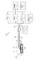
ここで図1を参照すると、組織部位において減圧を管理するための装置のブロック図が、本発明の例示的な実施形態に従って記載されている。具体的には、図1は、組織部位105に対する減圧を管理するための減圧処置システム100を示している。 Referring now to FIG. 1, a block diagram of an apparatus for managing reduced pressure at a tissue site is described in accordance with an exemplary embodiment of the present invention. Specifically, FIG. 1 shows a reduced
減圧処置システム100は、組織部位105に減圧処置を適用するために用いることができる。組織部位105は、任意の人、動物またはその他生命体の生体組織とすることができ、それには、骨組織、脂肪組織、筋肉組織、皮膚組織、血管組織、結合組織、軟骨、腱、靱帯または任意のその他組織が含まれるようにしてもよい。組織部位105は、創傷、病変組織または欠損組織を含むようにしてもよく、さらに、創傷、病変または欠損の無い健康な組織を含むものであってもよい。組織部位105への減圧の適用は、追加的な組織成長を促進すると同時に、組織部位105からの滲出液およびその他液体の排出を促すために用いることができる。組織部位105が創傷部位である場合には、肉芽組織の成長および滲出液と細菌の除去が、創傷の治癒を促す。健康組織を含む非創傷組織または非欠損組織への減圧の適用は、採取されて別の組織部位に移植されることとなる組織の成長を促すために使用することができる。 The reduced
組織部位105に加えられる減圧は減圧源110によって生成される。減圧源110は、手動で、あるいは機械的または電気的に操作される任意の種類のポンプであってもよい。減圧源110の非限定の実施例は、蓄積されたエネルギーによって駆動されて、減圧を発生させることができる装置を含む。蓄積されたエネルギー、減圧源の実施例には、ピエゾ電気エネルギー、バネエネルギー、太陽エネルギー、運動エネルギー、コンデンサに蓄えられたエネルギー、燃焼、並びに、スターリング(Sterling)または類似のサイクルによって開発されたエネルギーによって、駆動されるポンプが含まれるが、それらに限定されるものではない。減圧源110のその他の実施例には、手動で作動する装置、例えば、ベローズポンプ、蠕動ポンプ、隔膜ポンプ、回転翼ポンプ、線形ピストンポンプ、空気圧ポンプ、油圧ポンプ、ハンドポンプ、フットポンプ、手動で作動する噴霧ボトルとともに使用されるような手動ポンプなどが含まれる。減圧源110において使用または包含される、さらにその他の装置および方法には、注射器、送りネジ、歯止め装置、ぜんまい仕掛けの装置、振り子駆動装置、手動発電機、浸透処理、加熱処理、凝縮によって減圧が生成される処理が含まれる。 The reduced pressure applied to the
別の実施形態において、減圧源110は、化学反応によって駆動されるポンプを含むようにしてもよい。タブレット、溶液、スプレイまたはその他の送達メカニズムがポンプに送達されて、化学反応を開始させるために使用される。化学反応で生じた熱は、ポンプを駆動して減圧を生成するために使用するようにしてもよい。別の実施形態においては、ポンプを駆動して減圧を生成するために、CO2シリンダのような加圧ガスシリンダが使用される。さらに別の実施形態において、減圧源110は、バッテリ駆動ポンプであってもよい。ポンプは、少量の電力を使用するものであって、一回のバッテリ充電で長期間操作できることが望ましい。In another embodiment, the reduced
減圧源110は、被覆材115を介して組織部位105に減圧を提供する。被覆材115は、マニホールド120を含む。マニホールド120は、組織部位105に隣接して、あるいは組織部位105と接触して配置するようにしてもよい。マニホールド120は、組織部位105と隣接して配置することができ、減圧を組織部位105に分配することができる生体適合性の多孔質材料とするようにしてもよい。マニホールド120は、フォーム(発泡体)、ガーゼ、フェルト状マット、特定の生物学的応用に適したその他任意の材料であってもよい。マニホールド120は、減圧または流体の組織部位105への分配、並びに、組織部位105からの流体の分配を容易にするために複数の流路または通路を含むようにしてもよい。 The reduced
一実施形態において、マニホールド120は多孔質フォームであり、流路として機能する相互に連結された複数のセルまたは気孔を有する。多孔質フォームは、テキサス州サンアントニオのKinetic Concepts社によって製造されたGranuFoamのような、ポリウレタンオープンセル網状フォームであってもよい。オープンセル(連続気泡)フォームを使用する場合、気孔率は変化するようにしてもよいが、約400ミクロン乃至600ミクロンであることが望ましい。流路によって、オープンセルを有するマニホールド120部分の全体に亘って流体の流通が可能となっている。セルおよび流路は形状およびサイズが均一であるものであっても、あるいは形状およびサイズのパターン化された変化またはランダムな変化を含むものであってもよい。マニホールドのセルの形状およびサイズの変化は流路に変化をもたらし、かような特性は、マニホールド120を経由する流体の流動特性を変えるのに使用することができる。 In one embodiment, the manifold 120 is a porous foam and has a plurality of interconnected cells or pores that function as flow paths. The porous foam may be a polyurethane open cell reticulated foam such as GranFooam manufactured by Kinetic Concepts of San Antonio, Texas. When using open cell foam, the porosity may vary, but is preferably between about 400 microns and 600 microns. The flow path allows fluid to flow through the entire manifold 120 portion having open cells. The cells and channels may be uniform in shape and size, or may include patterned or random changes in shape and size. Changes in the shape and size of the cells in the manifold cause changes in the flow path, and such characteristics can be used to change the flow characteristics of the fluid through the manifold 120.
一実施形態において、マニホールド120は、“クローズドセル(独立気泡)”を含む部分をさらに有するものであってもよい。このマニホールド120のクローズドセル部分は複数のセルを含み、それらの大部分が隣接セルと流体流通可能には接続されていない。クローズドセル部分を、マニホールド120に選択的に配置して、マニホールド120の外周面を介した流体の伝播を防止するようにしてもよい。 In one embodiment, the manifold 120 may further include a portion that includes “closed cells”. The closed cell portion of the manifold 120 includes a plurality of cells, most of which are not connected in fluid communication with adjacent cells. The closed cell portion may be selectively disposed on the manifold 120 to prevent fluid propagation through the outer peripheral surface of the manifold 120.
また、マニホールド120は、減圧処置システム100の使用後に患者の体から取り除く必要がない生体吸収性材料から構成するようにしてもよい。適当な生体吸収性材料には、ポリ乳酸(PLA)とポリグリコール酸(PGA)のポリマーブレンドが含まれるようにしてもよいが、これに限定されるものではない。ポリマーブレンドには、ポリカーボネート、ポリフマレートおよびカプララクトン(capralactones)が含まれるが、これらに限定されるものではない。マニホールド120は、新たな細胞成長のための足場(scaffold)としてさらに機能するようにしてもよく、あるいは足場材料をマニホールド120とともに使用して細胞成長を促すようにしてもよい。足場は、細胞成長のための鋳型(template)を与える3次元多孔質構造のような、細胞の成長または組織の形成を増進または促進するのに使用される物質または構造である。足場材料の例示的な実施例には、リン酸カルシウム、コラーゲン、PLA/PGA、サンゴのヒドロキシアパタイト、炭酸塩、処理された同種移植片材料(processed allograft materials)が含まれる。一実施形態において、足場材料は、高いボイド率を有する(すなわち、空気の含有量が高い)。 The manifold 120 may also be constructed from a bioabsorbable material that does not need to be removed from the patient's body after use of the reduced
他の実施形態において、マニホールド120は、多孔質ヒドロゲルまたはヒドロゲル生成材料、布のような織物、セラミックス、薄版、生物製剤、バイオポリマー、コルクおよび止血被覆材から形成するようにしてもよい。代替的には、ビーズを組織部位105と接触するように配置して、減圧の分配に使用するようにしてもよい。 In other embodiments, the manifold 120 may be formed from porous hydrogels or hydrogel-generating materials, fabrics such as cloth, ceramics, thin plates, biologics, biopolymers, cork and hemostatic dressings. Alternatively, the beads may be placed in contact with the
被覆材115は、密封部材125も含む。マニホールド120は、密封部材125を使用して組織部位105に固定するようにしてもよい。密封部材125は、組織部位105においてマニホールド120を固定するために使用されるカバーであってもよい。密封部材125は、不透過性または半透過性とするようにしてもよいが、一実施例において、密封部材125は、マニホールド120の上方に密封部材125を取り付けた後に組織部位105において減圧を維持することができる。密封部材125は、シリコーンベースの化合物、アクリル、ヒドロゲルまたはヒドロゲル形成材料、または組織部位105に望ましい非透過性または透過性を有するその他任意の生体適合性材料からなるフレキシブルなドレープまたはフィルムとすることができる。密封部材125を疎水性材料により形成して、密封部材125による吸湿を防止するようにしてもよい。 The covering
ドレープのように“シート”形態で提供する代わりに、密封部材125は、組織部位105と接触するようにマニホールド120を配置した後にマニホールド120の上方に加えられる、流込み可能または噴霧可能な形態で提供するようにしてもよい。同様に、密封部材125は、マニホールド120および組織部位105の上方に配置されて密封機能性を与える装置を含むようにしてもよく、それには、吸着カップ、成型キャスト(molded cast)およびベルジャー(bell jar)が含まれるが、それらに限定されるものではない。 Instead of being provided in a “sheet” form, such as a drape, the sealing
一実施形態において、密封部材125は、マニホールド120周囲の組織および組織部位105との密封結合(sealed connection)を提供するように構成されている。密封結合は、密封部材125の周縁に沿って配置された接着剤または密封部材125の任意の部分に配置された接着剤により提供して、密封部材125をマニホールド120または組織部位105周囲の組織に固定するようにしてもよい。接着剤は、密封部材125上に予め配置するようにしても、あるいは、密封部材125の取付直前に密封部材125に噴霧あるいは別の方法で塗布されるようにしてもよい。 In one embodiment, sealing
粘着性の封止材の代替として、組織部位105に隣接する領域の周囲を密封部材125で包むことによって密封結合を提供するようにしてもよい。例えば、組織部位105が患者の四肢上に位置する場合には、細長いドレープまたは“ドレープテープ”をマニホールド120および組織部位105の周囲の領域に何度も巻いて、密封結合を提供することができる。代替的には、密封部材125と組織部位105周囲の組織との間の密封結合は、減圧処置システム100によって加えられた減圧により提供するようにしてもよい。この実施形態において、密封部材125の周囲は患者の皮膚に“真空”シールされる。さらに別の実施形態においては、密封部材125は、組織部位105周囲の組織に縫合して、密封結合を提供するようにしてもよい。 As an alternative to the adhesive sealant, a hermetic bond may be provided by wrapping the periphery of the region adjacent to the
ある場合には、密封部材125は、組織部位105を密封するために必要とされない場合もある。例えば、組織部位105は、減圧を維持するために“セルフシール”できるものであってもよい。皮下の深い組織創傷、空洞および瘻孔の場合には、密封部材125を使用しなくても、組織部位105における減圧の維持が可能である。多くの場合、そのような種類の組織部位を組織が包み込むか、あるいは囲い込むため、組織部位の組織が密封部材として有効に機能する。 In some cases, the sealing
減圧源110によって生成された減圧は、ソースチューブ(source tube)130および送達チューブ135を使って組織部位105に加えられるようにしてもよい。ソースチューブ130および送達チューブ135は、気体、液体、ゲルまたはその他流体が流れることができる任意のチューブとすることができる。例えば、組織部位105からの滲出液が送達チューブ135を通って流れるようにしてもよい。図1において、ソースライン130は減圧源110をキャニスタ140と連結し、送達チューブ135は、キャニスタ140を被覆材115に連結する。しかしながら、別の実施形態において、送達チューブ135を使用して、減圧源135を被覆材115に直接連結するようにしてもよい。 The reduced pressure generated by the reduced
ソースチューブ130および送達チューブ135は、任意の材料から作ることができる。ソースチューブ130および送達チューブ135は、柔軟性の有るものであっても、無いものであってもよい。また、ソースチューブ130および送達チューブ135は、流体が流れる1または複数の経路またはルーメンを含むものであってもよい。例えば、送達チューブ135は、2つのルーメンを含むものであってもよい。この実施例において、一方のルーメンは組織部位105からキャニスタ140への滲出液の流路として使用するようにしてもよい。他方のルーメンは、空気、抗菌剤、抗ウイルス剤、細胞成長促進剤、洗浄流体、またはその他化学活性薬剤のような流体を組織部位105に送達するために使用するようにしてもよい。それら流体をもたらす流体源は、図1には示されていない。減圧処置システム100のマルチルーメンチューブの内包物に関する追加的な詳細説明については、後述する。
一実施形態において、送達チューブ135は、連結部材145を介してマニホールド120に結合されている。連結部材145は、マニホールド120から送達チューブ135、またはその反対の流体の流れを許容する。例えば、マニホールド120を使用して組織部位105から集められた滲出液は、連結部材145を経由して送達チューブ135に流入する。別の実施形態において、減圧処置システム100は、連結部材145を含まない。この実施形態においては、送達チューブ135の一端がマニホールド120に隣接または接触するように、送達チューブ135を密封部材125またはマニホールド120の内部に直接的に挿入するようにしてもよい。 In one embodiment,
減圧処置システム100は、キャニスタ140を含む。組織部位105からの滲出液等の液体が送達チューブ135を通ってキャニスタ140内に流れるようにしてもよい。キャニスタ115は、気体や液体のような流体と同様に、固体を含む流体を収容することができる任意の装置または空洞とすることができる。例えば、キャニスタ115は、組織部位105からの滲出液を収容するようにしてもよい。ソースチューブ130および送達チューブ135は、直接キャニスタ140に連結するようにしても、あるいはコネクタ150のようなコネクタを介してキャニスタ140に連結するようにしてもよい。 The reduced
キャニスタ140は、送達チューブ135によってマニホールド120に流体流通可能に連結された、柔軟性のあるまたは柔軟性の無いキャニスタ、バッグまたはポーチとすることができる。キャニスタ140は、独立した容器であっても、滲出液および流体を収集するために減圧源110と操作可能に組み合わされるものであってもよい。減圧源110としてベローズポンプのような手動ポンプが使用される、ある例示的な実施形態において、減圧を生成する容量可変チャンバがキャニスタ140としても機能し、その拡大時に流体を収集するものであってもよい。キャニスタ140は、流体を収集する単一のチャンバを含むものであっても、あるいは複数のチャンバを含むものであってもよい。乾燥剤または吸収性材料をキャニスタ140内に配置して、流体を収集したときに流体を捕捉または制御するようにしてもよい。キャニスタ140を設けることなく、流体、特に水溶性の流体をマニホールド120から蒸発させるような、滲出液およびその他流体を制御する方法を用いるようにしてもよい。 The canister 140 can be a flexible or inflexible canister, bag or pouch that is fluidly connected to the manifold 120 by a
減圧処置システム100は圧力センサ155を含む。圧力センサ155は、組織部位105における実際の減圧を検出する。非限定の一実施例において、圧力センサ155は、シリコーン・ピエゾ抵抗ゲージ圧力センサである。一実施形態において、圧力センサ155は、減圧処置システム100内に含まれる唯一の圧力センサである。この実施形態において、減圧処置システム100は、圧力センサ155以外のその他の圧力センサを有していない。 The reduced
圧力センサ155は、制御チューブ160を介して組織部位105における減圧を検出する。制御チューブ160は、気体を流すことができる任意のチューブである。制御チューブ160は任意の材料から形成することができる。制御チューブ160は、柔軟性を有するものでも、有しないものであってよい。また、制御チューブ160は、流体を流すことができる1または複数の経路またはルーメンを含むものであってもよい。 The pressure sensor 155 detects reduced pressure in the
図1において、制御チューブ160は、コネクタ150を貫通するものとして示されている。しかしながら、制御チューブ160の配置は、特定の要求や利用に適合させるために変えるようにしてもよい。例えば、制御チューブ160はキャニスタ140を通るものであっても、キャニスタ140の外周に沿うものであっても、あるいはキャニスタ140を迂回するものであってもよい。圧力センサ155と反対側に位置する、制御チューブ160の端部を、コネクタ145を介してマニホールド120に結合させるようにしてもよい。別の実施例においては、制御チューブ160の一端がマニホールド120に隣接または接触するように、制御チューブ160を直接的に密封部材125またはマニホールド120の内部に挿入するようにしてもよい。 In FIG. 1, the
別の実施形態において、送達チューブ135および制御チューブ160は、単一のマルチルーメンチューブにおける各ルーメンである。ソースチューブ130および制御チューブ160も、単一のマルチルーメンチューブにおける各ルーメンとしてもよい。送達チューブ135のみを用いて減圧源110をマニホールド120に結合させる実施例においては、減圧源110と圧力センサ155の双方をマニホールド120に連結するために、単一のマルチルーメンチューブを使用するようにしてもよい。マルチルーメン実施形態に関する追加的な詳細説明は、図2および図3において後述する。 In another embodiment,
圧力センサ155は、減圧処置システム100上の何れの部位に設置するようにしてもよい。図1において、圧力センサ155は、組織部位105から離れた位置に示されている。この実施例において、組織部位105における減圧は、気体を流すことができる制御チューブ160を介して、離れた位置に配置された圧力センサ155から検出するようにしてもよい。また、この実施例においては、圧力センサを、減圧源110、キャニスタ140または減圧処置システム100のその他任意の例示の構成要素のような、その他の離れた位置に配置された減圧処置システム100の構成要素に直接的または間接的に連結するようにしてもよい。別の実施例において、圧力センサ155を、組織部位155に隣接して配置するようにしてもよい。この実施例において、圧力センサ155は、組織部位105における圧力を検出するために、制御チューブ160の使用を必要としない場合がある。非限定の一実施例において、圧力センサ155は、マニホールド120に直接的に結合されるか、あるいは密封部材125とマニホールド120との間に配置される。 The pressure sensor 155 may be installed at any location on the reduced
減圧処置システム100は、制御チューブバルブ165を含む。制御チューブバルブ165は、制御チューブ160に結合するようにしてもよい。制御チューブバルブ165は、制御チューブ160内の減圧を解放することができる任意のバルブとすることができる。制御チューブバルブ165の非限定の実施例には、空気電磁弁、比例弁または機械弁が含まれる。 The reduced
一実施形態において、制御チューブバルブ165は、人により手動で制御されるものであってもよい。別の実施形態においては、制御チューブバルブ165を、制御装置170により制御するようにしてもよい。一実施形態においては、制御チューブ160内の閉塞が検出されたときに、制御チューブバルブ165を開放して、制御チューブ160内の減圧を解放するようにしてもよい。このような閉塞は、例えば、組織部位105からの滲出液またはその他流体が制御チューブ160に詰まったときに発生する可能性がある。制御チューブバルブ165を介して制御チューブ160における減圧を解放することにより、制御チューブ160から閉塞を取り除くことができる。 In one embodiment, the control tube valve 165 may be manually controlled by a person. In another embodiment, the control tube valve 165 may be controlled by the
減圧処置システム100は、安全弁175も含む。安全弁175は、ソースチューブ130、キャニスタ140、コネクタ150、送達チューブ135、コネクタ145、減圧源110または被覆材115の何れか1つまたは任意の組合せに連結されたバルブとすることができる。安全弁175は、組織部位105における減圧を解放することができる任意の種類のバルブとすることができる。安全弁175の非限定の実施例には、空気電磁弁、比例弁または機械弁が含まれる。一実施例においては、組織部位105における減圧を解放するために、安全弁175を開放するようにしてもよい。また、組織部位105における減圧を管理するために、安全弁175を使用するようにしてもよい。組織部位105における減圧を管理するための、減圧処置システム100の安全弁175およびその他構成要素の使用に関する追加的な詳細説明は、後述する。 The reduced
減圧処置システムは制御装置170を含む。制御装置170は、圧力センサ155からのデータ等のデータを処理することができる任意の装置である。また、制御装置170は、減圧源110、安全弁175、制御チューブバルブ165、圧力センサ155または表示器180のような、減圧処置システム100の1または複数の構成要素の操作を制御するようにしてもよい。一実施形態において、制御装置170は、圧力センサ155からのデータ等のデータを受信・処理するとともに、減圧処置システム100の1または複数の構成要素の操作を制御して、組織部位105における減圧を管理する。 The reduced pressure treatment system includes a
一実施形態において、制御装置170は、組織部位105の目標減圧を決定する。目標減圧は、組織部位105におけるユーザが任意に定義可能な減圧であってもよい。また、目標減圧は、制御装置170によって決定されるものであってもよい。一実施例において、目標減圧は、組織部位105の効率的な処置を提供するとともに、組織部位105に減圧を加えることに付随する安全性の問題を考慮した減圧となっている。 In one embodiment, the
一実施例において、圧力センサ155は、組織部位105における減圧を検出する。減圧測定は、制御装置170により圧力センサ155から受信するようにしてもよい。制御装置170は、圧力センサ155から受信した減圧を目標減圧と比べて比較を形成するようにしてもよい。その後、制御装置170は、減圧処置システム100の構成要素を作動または管理して、上記比較に基づき、減圧管理機能を果たすようにしてもよい。 In one example, the pressure sensor 155 detects a reduced pressure at the
一実施形態において、制御装置170は、上記比較に基づいて減圧管理機能を果たす際に、実際の減圧が目標減圧を超えるのに応答して、減圧源110により生成される減圧を減少させる。例えば、減圧源110がモータ付きあるいは電気的に操作される減圧源である場合には、減圧源110が減圧の生成を減量するように、モータまたは電気的プロセスを減速するようにしてもよい。非限定の別の実施例において、減圧源110が、化学的に駆動される減圧源である場合には、減圧源110を駆動する化学プロセスを減速または変更して、減圧源110により生成される減圧量を減少させるようにしてもよい。 In one embodiment, the
別の実施例において、制御装置170は、圧力センサ155によって測定されるように、実際の減圧が目標減圧を予め定められた閾値以上超えるのに応答して、組織部位105における実際の減圧を減少させるために安全弁175を開放するようにしてもよい。上記予め定められた閾値は、ユーザによって決定するようにしても、あるいは制御装置170のような、減圧処置システム100の構成要素によって決定するようにしてもよい。一実施例において、上記予め定められた閾値は、組織部位105における組織の安全性を確保するのに役立つ閾値である。例えば、目標減圧を予め定められた閾値以上超える、組織部位105における実際の減圧が、組織部位105における組織の安全性に影響を与えることとなるように、上記予め定められた閾値を決定することができる。このため、この実施形態は、単一の圧力センサ155を使用した安全機構として、実施することができる。 In another embodiment, the
別の実施形態において、制御装置170は、圧力センサ155によって測定されるように、実際の減圧が目標減圧を予め定められた閾値以上超えるのに応答して、減圧源110を締めるまたは停止させるようにしてもよい。減圧源110を締めるまたは停止させることにより、組織部位105における減圧が減少する。一実施例において、それを超えたとき減圧源110が止められることとなる所定の閾値は、上記実施形態で述べたように、それを超えたとき安全弁175が開放されることとなる所定の閾値よりも大きいか、あるいはそれより小さい。このため、この実施例においては、組織部位105における組織の安全性を確保するために、二重の安全機構が採用されている。別の実施例においては、それを超えたときに減圧源110が止められることとなる所定の閾値が、それを超えたときに安全弁175が開放されることとなる所定の閾値と同じとなっている。 In another embodiment, the
別の実施例において、制御装置170は、上記比較に基づいて減圧管理機能を果たす際に、減圧源110により生成される減圧を増加させる。例えば、減圧源110がモータ付きあるいは電気的に操作される減圧源である場合には、減圧源110が減圧の生成を増量するように、モータまたは電気的プロセスの速度を増加させるようにしてもよい。非限定の別の実施例において、減圧源110が、化学的に駆動される減圧源である場合には、減圧源110を駆動する化学プロセスを加速または変更して、減圧源110により生成される減圧量を増加させるようにしてもよい。 In another embodiment, the
別の実施形態において、制御装置170は、圧力センサ155によって測定されるように、減圧源110からの生成減圧の増加に対する、組織部位105における実際の減圧の反応性を測定する。一実施例においては、制御装置170が、減圧源によって生成される減圧が増加または減少したときに検出するようにしてもよい。例えば、制御装置170は、減圧源110のモータ速度、化学反応速度または圧縮速度が増加または減少したときに検出することができるものであってもよい。このような増加または減少を判定するために制御装置170によって検出される可能性があるその他のパラメータには、ポンプの負荷を示すこととなるモータの電流引き込みが含まれる。必要な減圧を組織部位105に送達するためにモータに与える必要がある電力レベルまたはパルス幅変調も、検出されるようにしてもよい。制御装置170は、圧力センサ155によって測定された実際の減圧と目標減圧との比較に基づいて、減圧源によって生成される減圧が増加または減少することを推定できるものであってもよい。 In another embodiment, the
一実施形態において、制御装置170は、圧力センサ155によって測定されるように、組織部位105における実際の減圧が、生成される減圧の増加に無反応であることに応答して、表示器180に信号を出力させる。一実施形態において、表示器180は、発光ダイオード、すなわちLEDである。この実施形態において、表示器180は、組織部位105における実際の減圧が、生成される減圧の増加に無反応であることに応答して、発光する。 In one embodiment, the
別の実施形態において、表示器180はスピーカ等の音発生装置である。この実施形態において、表示器180は、組織部位105における実際の減圧が、生成される減圧の増加に無反応であることに応答して、音を発する。 In another embodiment, the indicator 180 is a sound generator such as a speaker. In this embodiment, the indicator 180 emits a sound in response to the actual reduced pressure at the
別に実施形態において、組織部位105における実際の減圧が、生成減圧の増加に応答して所定時間以内に増加しないときには、組織部位105における実際の減圧が、生成減圧の増加に反応していないことになる。このような無反応は、送達チューブ135またはソースチューブ130のような、減圧処置システム100の構成要素の1または複数が閉塞または漏れを生じていることを示している可能性がある。例えば、組織部位105からの滲出液のような液体は、送達チューブ135またはソースチューブ130を詰まらせる可能性がある。別の実施例においては、送達チューブ135またはソースチューブ130に沿うある部位に破裂が生じている可能性がある。 In another embodiment, when the actual reduced pressure at the
上記所定時間は、任意の時間とすることができ、減圧処置システム100のユーザによって設定されるものであっても、制御装置170のような、減圧処置システム100の一構成要素によって設定されるものであってもよい。一実施例において、上記所定時間は、1秒乃至10秒の範囲、または4秒乃至6秒の範囲である。特定の非限定の一実施例において、上記所定時間は5秒である。 The predetermined time can be any time, and is set by one component of the reduced
別の実施形態においては、生成される減圧の増加に応答して、予め定められた時間内に組織部位105における実際の減圧が目標減圧に達しないときは、組織部位105における実際の減圧が、生成される減圧の増加に反応していない。前述した実施形態と同様、このような無反応は、送達チューブ135またはソースチューブ130のような、減圧処置システム100の1または複数の構成要素が閉塞または漏れを生じていることを示している可能性がある。 In another embodiment, in response to an increase in the generated reduced pressure, when the actual reduced pressure at the
本発明の別の実施形態において、減圧源110が真空ポンプおよびモータである場合には、ポンプまたはモータ速度を測定するために、真空ポンプまたはモータにセンサを結合するようにしてもよい。このセンサによって得られた測定結果は、ポンプによって送達された圧力を推定するために使用することができ、これにより、漏れまたは閉塞が存在するか否かを判定してその何れであるかを区別するための機構を提供することができる。例えば、漏れの検出は、モータとポンプの何れか一方または両方の速度を監視することによって、実行することができる。減圧処置が施されている間に漏れが生じた場合には、より多くの減圧をポンプが生成していることを示して、モータ速度とポンプ速度の一方または両方が増加する可能性が高い。閉塞が生じた場合には、モータとポンプの一方または両方の速度が低下する可能性が高い。ポンプまたはモータ速度センサからの出力は、漏れまたは閉塞状態の間に表示器180を使用して信号を発するために、制御装置170により使用されるようにしてもよい。 In another embodiment of the invention, if the
特定の例示的な一実施例において、減圧源110は、変速装置を有するモータを含む。この実施例において、センサがモータの速度を検出するようにしてもよい。モータの速度が閾値より変化したときに、表示器180が信号を発するようにしてもよい。閾値は任意の値とすることができ、減圧処置システム100のユーザによって設定されるものであっても、制御装置170のような、減圧処置システム100の一構成要素によって設定されるものであってもよい。閾値は、有限量、パーセント、またはそれらの任意の組合せを単位として表現することができる。 In one particular exemplary embodiment, the reduced
ここで図2を参照すると、マルチルーメンチューブの斜視図が、本発明の例示的な一実施形態に従って記載されている。具体的には、図2は、図1の減圧処置システム100等の減圧処置システムにおいて実装されるようなマルチルーメンチューブ200を示している。 Referring now to FIG. 2, a perspective view of a multi-lumen tube is described in accordance with an exemplary embodiment of the present invention. Specifically, FIG. 2 shows a
マルチルーメンチューブ200は、2つのルーメンを含む。具体的には、マルチルーメンチューブ200はルーメン235,260を含む。マルチルーメンチューブ200は2つのルーメン235,260を含むが、3,4または10など、任意の数のルーメンを備えるものであってもよい。
一実施形態において、ルーメン235,260の一方、例えばルーメン235は、図1の送達チューブ135またはソースチューブ130のような、送達チューブまたはソースチューブである。別の実施形態において、ルーメン235,260の一方、例えばルーメン260は、図1の制御チューブ160のような制御チューブである。送達チューブ、ソースチューブおよび制御チューブの組合せをルーメンとして単一のマルチルーメンチューブ内に組み込むことによって、減圧処置システムに含まれる個別チューブの数量を減少させることができる。チューブの数を減らすことによって、ユーザが使用するための減圧処置システムを簡素化するとともに、減圧処置システムを運ぶ負荷を軽減する。 In one embodiment, one of
ここで図3を参照すると、マルチルーメンチューブの斜視図が、本発明の例示的な一実施形態に従って記載されている。具体的には、図3は、図1の減圧処置システム100等の減圧処置システムにおいて実装されるようなマルチルーメンチューブ300を示している。マルチルーメンチューブ300は、図2のマルチルーメンチューブ200の非限定の一実施例であってもよい。 Referring now to FIG. 3, a perspective view of a multi-lumen tube is described in accordance with an exemplary embodiment of the present invention. Specifically, FIG. 3 shows a
マルチルーメンチューブ300は、9つのルーメンを含む。具体的には、マルチルーメンチューブ300は、ルーメン335と周辺のルーメン360を含む。マルチルーメンチューブ300は、ルーメン335を取り囲むものとして周辺のルーメン360を示しているが、マルチルーメンチューブ300内のルーメンは、互いに関連した任意の空間構成を有するものであってもよい。
一実施形態において、ルーメン335および360の1つ、例えばルーメン335は、図1の送達チューブ135またはソースチューブ130のような、送達チューブまたはソースチューブである。別の実施形態において、ルーメン335,360の1つ、例えば、ルーメン360の何れかまたはすべては、図1の制御チューブ160のような制御チューブである。図3におけるマルチルーメンチューブ300と同様に、送達チューブ、ソースチューブおよび制御チューブの任意の組合せをルーメンとしてマルチルーメンチューブ300内に組み込むことによって、減圧処置システムに含まれる個別チューブの数量を減少させることができ、これにより、マルチルーメンチューブが含まれるような減圧処置システムの有用性を増加させることができる。 In one embodiment, one of
図4を参照すると、組織部位において減圧を管理するための方法を示すフローチャートが、本発明の例示的な実施形態に従って記載されている。図4に示す方法は、図1の減圧処置システム100の構成要素など、減圧処置システムの他の構成要素と協働して、図1の制御装置170のような制御装置が実施するものであってもよい。 Referring to FIG. 4, a flowchart illustrating a method for managing reduced pressure at a tissue site is described in accordance with an exemplary embodiment of the present invention. The method shown in FIG. 4 is performed by a control device such as the
この方法においては、目標減圧を決定することによって開始する(ステップ405)。上記方法においては、単一の圧力センサを使用して組織部位における実際の減圧を検出する(ステップ410)。上記方法においては、実際の減圧を目標減圧と比べて比較結果を形成する(ステップ415)。上記方法においては、上記比較結果に基づいて減圧管理機能を実行する(ステップ420)。 The method begins by determining a target pressure reduction (step 405). In the method, a single pressure sensor is used to detect the actual reduced pressure at the tissue site (step 410). In the above method, the actual reduced pressure is compared with the target reduced pressure to form a comparison result (step 415). In the method, the decompression management function is executed based on the comparison result (step 420).
図5を参照すると、組織部位において減圧を管理するための方法を示すフローチャートが、本発明の例示的な実施形態に従って記載されている。図5に示す方法は、図1の減圧処置システム100の構成要素など、減圧処置システムの他の構成要素と協働して、図1の制御装置170のような制御装置が実施するものであってもよい。図5に示す方法は、例示的な実施形態と、図4のステップ415および420に関する追加的な詳細説明を与える。 Referring to FIG. 5, a flowchart illustrating a method for managing reduced pressure at a tissue site is described in accordance with an exemplary embodiment of the present invention. The method shown in FIG. 5 is performed by a control device such as the
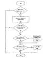
この方法においては、実際の減圧が目標減圧を超えるかどうかを判定することによって開始する(ステップ505)。実際の減圧が目標減圧を超えていないと判定した場合には、この方法は終了となる。ステップ505において、実際の減圧が目標減圧を超えていると判定した場合には、減圧源によって生成される減圧を減少させる(ステップ510)。 The method begins by determining whether the actual reduced pressure exceeds the target reduced pressure (step 505). If it is determined that the actual reduced pressure does not exceed the target reduced pressure, the method ends. If it is determined in
上記方法においては、実際の減圧が目標減圧を、予め設定した閾値以上超えるかどうかを判定する(ステップ515)。実際の減圧が目標減圧を、予め設定した閾値以上は超えていないと判定した場合には、この方法は終了となる。ステップ515において、実際の減圧が目標減圧を、予め設定した閾値以上超えていると判定した場合には、安全弁を開放することによって減圧を減少させるかどうかを判定する(ステップ520)。安全弁を開放することによって減圧を減少させると判定した場合には、安全弁を開放して、組織部位における実際の減圧を減少させる(ステップ525)。 In the above method, it is determined whether or not the actual reduced pressure exceeds the target reduced pressure by a preset threshold value or more (step 515). If it is determined that the actual decompression does not exceed the target decompression above a preset threshold, the method ends. If it is determined in
ステップ520において、安全弁を開放することによっては減圧を減少させないと判定した場合には、減圧源を止めることによって減圧を減少させるかどうかを判定する(ステップ530)。減圧源を止めることによって減圧を減少させると判定した場合には、減圧源を止める(ステップ535)。その後、この方法は終了となる。ステップ530において、減圧源を止めることによっては減圧を減少させないと判定した場合には、この方法は終了となる。 If it is determined in step 520 that the reduced pressure is not decreased by opening the safety valve, it is determined whether the reduced pressure is decreased by stopping the reduced pressure source (step 530). If it is determined that the reduced pressure is reduced by stopping the reduced pressure source, the reduced pressure source is stopped (step 535). Thereafter, the method ends. If it is determined in
図6を参照すると、組織部位において減圧を管理するための方法を示すフローチャートが、本発明の例示的な実施形態に従って記載されている。図6に示す方法は、図1の減圧処置システム100の構成要素など、減圧処置システムの他の構成要素と協働して、図1の制御装置170のような制御装置が実施するものであってもよい。図5に示す方法は、例示的な実施形態と、図4のステップ415および420に関する追加的な詳細説明を与える。 Referring to FIG. 6, a flowchart illustrating a method for managing reduced pressure at a tissue site is described in accordance with an exemplary embodiment of the present invention. The method shown in FIG. 6 is performed by a control device such as the
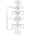
この方法においては、目標減圧が実際の減圧を超えるかどうかを判定することによって開始する(ステップ605)。目標減圧が実際の減圧を超えていないと判定した場合には、この方法は終了となる。ステップ605において、目標減圧が実際の減圧を超えていると判定した場合には、減圧源によって生成される減圧を増加させる(ステップ610)。 The method begins by determining whether the target pressure reduction exceeds the actual pressure reduction (step 605). If it is determined that the target pressure reduction does not exceed the actual pressure reduction, the method ends. If it is determined in
上記方法においては、単一の圧力センサによって測定される実際の減圧が、生成減圧の増加に反応するかどうかを判定する(ステップ615)。単一の圧力センサによって測定される実際の減圧が、生成減圧の増加にすぐに反応すると判定した場合には、この方法は終了となる。ステップ615において、単一の圧力センサによって測定される実際の減圧が、生成減圧の増加に反応していないと判定した場合には、表示器を使用して信号を発する(ステップ620)。その後、この方法は終了となる。 In the method, it is determined whether the actual reduced pressure measured by a single pressure sensor responds to an increase in the generated reduced pressure (step 615). If it is determined that the actual reduced pressure measured by a single pressure sensor responds immediately to the increase in the generated reduced pressure, the method ends. If, in
図7を参照すると、組織部位において減圧を管理するための方法を示すフローチャートが、本発明の例示的な実施形態に従って記載されている。図7に示す方法は、図1の減圧処置システム100の構成要素など、減圧処置システムの他の構成要素と協働して、図1の制御装置170のような制御装置が実施するものであってもよい。図7に示す方法は、例示的な実施形態と、図6のステップ615および620に関する追加的な詳細説明を与える。 Referring to FIG. 7, a flowchart illustrating a method for managing reduced pressure at a tissue site is described in accordance with an exemplary embodiment of the present invention. The method shown in FIG. 7 is performed by a control device such as the
この方法においては、組織部位における実際の減圧が、予め定められた時間内に増加するかどうかを判定することによって開始する(ステップ705)。組織部位における実際の減圧が、予め定められた時間内に増加していないと判定した場合には、表示器を使用して信号を発する(ステップ710)。その後、この方法は終了となる。 The method begins by determining whether the actual reduced pressure at the tissue site increases within a predetermined time (step 705). If it is determined that the actual reduced pressure at the tissue site has not increased within a predetermined time, a signal is generated using a display (step 710). Thereafter, the method ends.
一方、ステップ705において、組織部位における実際の減圧が、予め定められた時間内に増加していると判定した場合には、組織部位における実際の減圧が、予め定められた時間内に目標減圧に達するかどうかを判定する(ステップ715)。組織部位における実際の減圧が、予め定められた時間内に目標減圧に達しないと判定した場合には、表示器を使用して信号を発する(ステップ710)。その後、この方法は終了となる。一方、ステップ715において、組織部位における実際の減圧が、予め定められた時間内に目標減圧に達すると判定した場合には、この方法は終了となる。 On the other hand, if it is determined in
示された異なる実施形態におけるフローチャートおよびブロック図は、アーキテクチャーを機能的に示すとともに、装置および方法の幾つかの可能性のある実施の操作を示している。幾つかの代替的な実施において、機能、またはブロックに記載されている機能は、図面に記載されている順序以外で生じるようにしてもよい。例えば、幾つかの場合、含まれる機能に応じて、連続して示される2ブロックをほぼ同時に実行してもよく、あるいは、それらブロックを反対の順序で実行できるときもある。 The flowcharts and block diagrams in the different illustrated embodiments illustrate the architecture functionally and illustrate some possible implementation operations of the apparatus and method. In some alternative implementations, the functions or functions described in the blocks may occur out of the order described in the drawings. For example, in some cases, two blocks shown in succession may be executed substantially simultaneously, depending on the functions involved, or they may be executed in the opposite order.
例示的な実施形態は、現在使用されている減圧処置システムよりも少ない電力を消費する低コストで軽量なシステムとして構成することも可能である。システムが低重度の創傷や歩行可能な患者の創傷の治療に使用されるとき、サイズと重量の減少は、特に重要である。それらの創傷や患者は、患者への不快感や動作の妨げを最小とするために、目立たなくて軽量なシステムを必要としている。 The exemplary embodiment can also be configured as a low cost, lightweight system that consumes less power than currently used reduced pressure treatment systems. Size and weight reduction is particularly important when the system is used to treat low severity wounds or ambulatory patient wounds. These wounds and patients require an inconspicuous and lightweight system to minimize patient discomfort and impediments to movement.
コスト、重量および電力消費を最小化する1つの方法は、圧力を測定するためにセンサを1基のみ使用することを通じてなされる。上述したように、従来のシステムは、一般に2基のセンサを使用しており、1基を組織部位における圧力測定に、もう1基を減圧源における圧力測定に使用している。しかしながら、減圧源における圧力を測定する圧力センサを除去することによって、必要な電子回路の量およびシステムによって消費される電力量を大幅に低減させることが可能となる。さらに、2基のセンサの示度を比較するために使用される回路およびソフトウェアを除去することができる。また、例示的な実施形態は、組織に対して予め設定された減圧を加えることを可能にするとともに、従来のシステムよりも少ない構成要素で、ある異常なシステム状態の検出および通知を提供する。 One way to minimize cost, weight and power consumption is through the use of only one sensor to measure pressure. As described above, conventional systems typically use two sensors, one for measuring pressure at a tissue site and the other for measuring pressure at a reduced pressure source. However, by removing the pressure sensor that measures the pressure at the reduced pressure source, it is possible to significantly reduce the amount of electronic circuitry required and the amount of power consumed by the system. In addition, the circuitry and software used to compare the readings of the two sensors can be eliminated. The exemplary embodiments also allow for applying a pre-set decompression to the tissue and provide detection and notification of certain abnormal system conditions with fewer components than conventional systems.
例示的な実施形態は、減圧源における測定値を使用して組織部位圧力に近付ける必要性も取り除くことができる。さらに、例示的な実施形態のその他の特徴に付随しているとき、組織部位における圧力を直接測定することによって、減圧処置システムは、減圧源でなされた操作変更に応答する組織部位における圧力変化を観察することで、漏れおよび閉塞を検出することが可能となる。 Exemplary embodiments may also eliminate the need to use tissue measurements at a reduced pressure source to approximate tissue site pressure. Further, when associated with other features of the exemplary embodiment, by directly measuring the pressure at the tissue site, the reduced pressure treatment system allows the pressure change at the tissue site to respond to operational changes made at the reduced pressure source. By observing it, it becomes possible to detect leakage and blockage.
Claims (21)
Translated fromJapanese組織部位における圧力測定値を示す検出データを、組織部位に流体接続された単一のセンサから受信し、
減圧源の動作パラメータを示すデータを取得し、かつ、
前記動作パラメータの変化および受信した検出データに基づいて、漏れと閉塞とを区別するように構成されていることを特徴とする制御装置。A control device for managing decompression at a tissue site,
Receiving detection data indicative of pressure measurements at the tissue site from a single sensor fluidly connected to the tissue site;
Obtaining data indicating operating parameters of the decompression source, and
A control device configured to distinguish between leakage and blockage based on a change in the operating parameter and received detection data.
前記制御装置に接続されかつソース導管に流体接続されたバルブをさらに備えることを特徴とする制御装置。The control device according to claim 1,
A control device further comprising a valve connected to the control device and fluidly connected to a source conduit.
前記制御装置は、閉塞が存在する場合に、前記バルブを排気させるように構成することで、前記ソース導管における減圧を解放するように構成されていることを特徴とする制御装置。The control device according to claim 2,
The control device is configured to release the pressure reduction in the source conduit by evacuating the valve when a blockage exists.
前記制御装置が、前記減圧源により生成される減圧を変化させるように構成されていることを特徴とする制御装置。The control device according to claim 1,
The control device is configured to change a reduced pressure generated by the reduced pressure source.
前記制御装置が、圧力測定値が前記動作パラメータに無反応であるか否かを判定するように構成されていることを特徴とする制御装置。The control device according to claim 1,
The control device is configured to determine whether a pressure measurement value is unresponsive to the operating parameter.
前記制御装置が、圧力測定値が前記動作パラメータの変化に無反応である場合に信号を与えるように構成されていることを特徴とする制御装置。The control device according to claim 5,
The control device is configured to provide a signal when a pressure measurement is insensitive to changes in the operating parameter.
前記制御装置が、前記動作パラメータが増加する場合に漏れを示す第1信号を与え、前記動作パラメータが減少する場合に閉塞を示す第2信号を与えるように構成されていることを特徴とする制御装置。The control device according to claim 5,
The control device is configured to provide a first signal indicating leakage when the operating parameter increases and to provide a second signal indicating blockage when the operating parameter decreases. apparatus.
前記制御装置は、
目標減圧を決定すること、
前記目標減圧が圧力測定値を上回る場合に、前記減圧源により生成される減圧を増加させること、並びに、
前記減圧源により生成される減圧を増加させた後に、圧力測定値が増加しないか否かを判定することによって、
圧力測定値が無反応であることを判定するように構成されていることを特徴とする制御装置。The control device according to claim 5,
The controller is
Determining a target decompression,
Increasing the reduced pressure generated by the reduced pressure source when the target reduced pressure exceeds a pressure measurement; and
By determining whether the pressure reading does not increase after increasing the reduced pressure generated by the reduced pressure source,
A control device configured to determine that the pressure measurement value is unresponsive.
前記制御装置に接続されかつ組織部位における減圧を低下させるように構成された安全弁をさらに備えることを特徴とする制御装置。The control device according to claim 8, wherein
A control device further comprising a safety valve connected to the control device and configured to reduce reduced pressure at a tissue site.
前記制御装置は、組織部位における圧力測定値が予め設定された閾値以上、前記目標減圧を超える場合に、組織部位における減圧を低下させるように構成されていることを特徴とする制御装置。The control device according to claim 9,
The control device is configured to reduce the pressure reduction in the tissue site when the pressure measurement value in the tissue site exceeds the target pressure reduction by a predetermined threshold value or more.
前記動作パラメータが、電流の流れ、モータの速度および化学反応からなる群から選択されることを特徴とする制御装置。The control device according to claim 1,
The control device, wherein the operating parameter is selected from the group consisting of current flow, motor speed and chemical reaction.
前記制御装置が、前記動作パラメータを変更するように構成されていることを特徴とする制御装置。The control device according to claim 11,
The control device is configured to change the operation parameter.
ソース導管に流体接続された減圧源と、
組織部位に流体接続された単一のセンサと、
前記単一のセンサから受信した検出データと、前記減圧源の動作パラメータを示す取得したデータとに基づいて、前記システムにおける漏れまたは閉塞を識別するように構成された制御装置とを備えることを特徴とするシステム。A system for managing decompression at a tissue site,
A vacuum source fluidly connected to the source conduit;
A single sensor fluidly connected to the tissue site;
A controller configured to identify a leak or blockage in the system based on detection data received from the single sensor and acquired data indicative of operating parameters of the reduced pressure source. System.
前記制御装置に接続されかつ前記ソース導管に流体接続されたバルブをさらに備えることを特徴とするシステム。The system of claim 13, wherein
The system further comprising a valve connected to the controller and fluidly connected to the source conduit.
前記バルブは、閉塞が識別される場合に、前記ソース導管における減圧を解放するようにように構成されていることを特徴とするシステム。The system of claim 14, wherein
The system, wherein the valve is configured to release a vacuum in the source conduit when an occlusion is identified.
漏れを示す第1信号と、閉塞を示す第2信号とをさらに含むことを特徴とするシステム。The system of claim 13, wherein
The system further comprising a first signal indicating leakage and a second signal indicating occlusion.
前記制御装置が、前記単一のセンサにより測定された圧力が前記動作パラメータに無反応であるか否かを判定するように構成されていることを特徴とするシステム。The system of claim 13, wherein
The system wherein the controller is configured to determine whether the pressure measured by the single sensor is insensitive to the operating parameter.
前記制御装置は、
目標減圧を決定すること、
前記目標減圧が圧力測定値を上回る場合に、前記減圧源により生成される減圧を増加させること、並びに、
前記減圧源により生成される減圧を増加させた後に、圧力測定値が増加しないか否かを判定することによって、
圧力測定値が無反応であることを判定するように構成されていることを特徴とするシステム。The system of claim 17, wherein
The controller is
Determining a target decompression,
Increasing the reduced pressure generated by the reduced pressure source when the target reduced pressure exceeds a pressure measurement; and
By determining whether the pressure reading does not increase after increasing the reduced pressure generated by the reduced pressure source,
A system configured to determine that a pressure measurement is unresponsive.
組織部位に連通する安全弁をさらに備えることを特徴とするシステム。The system of claim 13, wherein
A system further comprising a safety valve communicating with the tissue site.
前記安全弁は、組織部位における圧力測定値が予め設定された閾値以上、前記目標減圧を超える場合に、組織部位における減圧を低下させるように構成されていることを特徴とするシステム。The system of claim 19, wherein
The safety valve is configured to reduce the reduced pressure in the tissue site when the pressure measurement value in the tissue site exceeds the target reduced pressure by a predetermined threshold value or more.
組織部位における圧力測定値を示す検出データを単一のセンサから取得し、
減圧源に関連する動作パラメータを示すデータを取得し、かつ、
圧力測定値が前記動作パラメータの変化に無反応であるか否かを判定するように構成されていることを特徴とする処理ユニット。
A processing unit for managing decompression,
Obtaining detection data from a single sensor indicating pressure measurements at the tissue site;
Obtaining data indicating operating parameters associated with the decompression source; and
A processing unit configured to determine whether a pressure measurement is insensitive to changes in the operating parameter.
Applications Claiming Priority (2)
| Application Number | Priority Date | Filing Date | Title |
|---|---|---|---|
| US90055607P | 2007-02-09 | 2007-02-09 | |
| US60/900,556 | 2007-02-09 |
Related Parent Applications (1)
| Application Number | Title | Priority Date | Filing Date |
|---|---|---|---|
| JP2016022522ADivisionJP6249459B2 (en) | 2007-02-09 | 2016-02-09 | System and method for managing decompression at a tissue site |
Publications (2)
| Publication Number | Publication Date |
|---|---|
| JP2018047271Atrue JP2018047271A (en) | 2018-03-29 |
| JP6657165B2 JP6657165B2 (en) | 2020-03-04 |
Family
ID=39690401
Family Applications (5)
| Application Number | Title | Priority Date | Filing Date |
|---|---|---|---|
| JP2009549123AActiveJP5122586B2 (en) | 2007-02-09 | 2008-02-08 | System and method for managing decompression at a tissue site |
| JP2012061520AActiveJP5542165B2 (en) | 2007-02-09 | 2012-03-19 | System and method for managing decompression at a tissue site |
| JP2012234432AActiveJP5930466B2 (en) | 2007-02-09 | 2012-10-24 | System and method for managing decompression at a tissue site |
| JP2016022522AActiveJP6249459B2 (en) | 2007-02-09 | 2016-02-09 | System and method for managing decompression at a tissue site |
| JP2017219586AActiveJP6657165B2 (en) | 2007-02-09 | 2017-11-15 | System and method for managing reduced pressure at a tissue site |
Family Applications Before (4)
| Application Number | Title | Priority Date | Filing Date |
|---|---|---|---|
| JP2009549123AActiveJP5122586B2 (en) | 2007-02-09 | 2008-02-08 | System and method for managing decompression at a tissue site |
| JP2012061520AActiveJP5542165B2 (en) | 2007-02-09 | 2012-03-19 | System and method for managing decompression at a tissue site |
| JP2012234432AActiveJP5930466B2 (en) | 2007-02-09 | 2012-10-24 | System and method for managing decompression at a tissue site |
| JP2016022522AActiveJP6249459B2 (en) | 2007-02-09 | 2016-02-09 | System and method for managing decompression at a tissue site |
Country Status (14)
| Country | Link |
|---|---|
| US (3) | US8409170B2 (en) |
| EP (3) | EP2109472B2 (en) |
| JP (5) | JP5122586B2 (en) |
| KR (1) | KR101217918B1 (en) |
| CN (1) | CN101605568B (en) |
| AU (1) | AU2008216781B2 (en) |
| BR (1) | BRPI0806221A2 (en) |
| CA (1) | CA2673842C (en) |
| IL (1) | IL199778A0 (en) |
| MX (1) | MX2009008397A (en) |
| RU (1) | RU2428208C2 (en) |
| TW (2) | TW201219070A (en) |
| WO (1) | WO2008100440A1 (en) |
| ZA (1) | ZA200904308B (en) |
Cited By (3)
| Publication number | Priority date | Publication date | Assignee | Title |
|---|---|---|---|---|
| JP2021536273A (en)* | 2018-08-29 | 2021-12-27 | アートラ・メディカル、エルエルシーAatru Medical, Llc | Negative pressure treatment with mechanical chemical pump |
| JP2022531699A (en)* | 2019-05-07 | 2022-07-08 | アロア・バイオサージェリー・リミテッド | Negative pressure wound dressing |
| JP2023518351A (en)* | 2020-03-23 | 2023-05-01 | ティージェイ スミス アンド ネフュー リミテッド | Self-testing of negative pressure wound therapy devices |
Families Citing this family (272)
| Publication number | Priority date | Publication date | Assignee | Title |
|---|---|---|---|---|
| GB0224986D0 (en) | 2002-10-28 | 2002-12-04 | Smith & Nephew | Apparatus |
| CN1822874B (en) | 2003-07-22 | 2010-10-13 | 凯希特许有限公司 | Negative pressure wound treatment dressing |
| GB0325129D0 (en) | 2003-10-28 | 2003-12-03 | Smith & Nephew | Apparatus in situ |
| US8062272B2 (en) | 2004-05-21 | 2011-11-22 | Bluesky Medical Group Incorporated | Flexible reduced pressure treatment appliance |
| US10058642B2 (en) | 2004-04-05 | 2018-08-28 | Bluesky Medical Group Incorporated | Reduced pressure treatment system |
| US7909805B2 (en) | 2004-04-05 | 2011-03-22 | Bluesky Medical Group Incorporated | Flexible reduced pressure treatment appliance |
| CA2949821C (en) | 2005-09-06 | 2021-05-18 | Smith & Nephew, Inc. | Self contained wound dressing with micropump |
| US8338402B2 (en)* | 2006-05-12 | 2012-12-25 | Smith & Nephew Plc | Scaffold |
| EP1905465B2 (en) | 2006-09-28 | 2013-11-27 | Smith & Nephew, Inc. | Portable wound therapy system |
| ES2564519T3 (en) | 2006-10-13 | 2016-03-23 | Bluesky Medical Group Inc. | Pressure control of a medical vacuum pump |
| AU2007311028B2 (en)* | 2006-10-17 | 2013-06-27 | Smith & Nephew Plc | Auxiliary powered negative pressure wound therapy apparatuses and methods |
| US7967810B2 (en) | 2006-10-20 | 2011-06-28 | Mary Beth Kelley | Sub-atmospheric wound-care system |
| RU2428208C2 (en) | 2007-02-09 | 2011-09-10 | КейСиАй Лайсензинг Инк. | System and method of low pressure control in tissue area |
| CA2674997C (en) | 2007-02-09 | 2012-08-14 | Kci Licensing, Inc. | A breathable interface system for topical reduced pressure |
| EP2129409B2 (en) | 2007-03-14 | 2021-11-24 | The Board of Trustees of the Leland Stanford Junior University | Devices for application of reduced pressure therapy |
| GB0712736D0 (en)* | 2007-07-02 | 2007-08-08 | Smith & Nephew | Apparatus |
| GB0712764D0 (en) | 2007-07-02 | 2007-08-08 | Smith & Nephew | Carrying Bag |
| GB0712763D0 (en) | 2007-07-02 | 2007-08-08 | Smith & Nephew | Apparatus |
| GB0715259D0 (en) | 2007-08-06 | 2007-09-12 | Smith & Nephew | Canister status determination |
| US9408954B2 (en) | 2007-07-02 | 2016-08-09 | Smith & Nephew Plc | Systems and methods for controlling operation of negative pressure wound therapy apparatus |
| GB0712739D0 (en) | 2007-07-02 | 2007-08-08 | Smith & Nephew | Apparatus |
| US12121648B2 (en) | 2007-08-06 | 2024-10-22 | Smith & Nephew Plc | Canister status determination |
| WO2009067711A2 (en)* | 2007-11-21 | 2009-05-28 | T.J. Smith & Nephew, Limited | Suction device and dressing |
| EP2214612B1 (en) | 2007-11-21 | 2019-05-01 | Smith & Nephew PLC | Wound dressing |
| GB0722820D0 (en) | 2007-11-21 | 2008-01-02 | Smith & Nephew | Vacuum assisted wound dressing |
| ES2715605T3 (en) | 2007-11-21 | 2019-06-05 | Smith & Nephew | Wound dressing |
| US11253399B2 (en) | 2007-12-06 | 2022-02-22 | Smith & Nephew Plc | Wound filling apparatuses and methods |
| GB0723855D0 (en) | 2007-12-06 | 2008-01-16 | Smith & Nephew | Apparatus and method for wound volume measurement |
| US20130096518A1 (en) | 2007-12-06 | 2013-04-18 | Smith & Nephew Plc | Wound filling apparatuses and methods |
| GB0723872D0 (en) | 2007-12-06 | 2008-01-16 | Smith & Nephew | Apparatus for topical negative pressure therapy |
| GB0723874D0 (en)* | 2007-12-06 | 2008-01-16 | Smith & Nephew | Dressing |
| GB2455962A (en) | 2007-12-24 | 2009-07-01 | Ethicon Inc | Reinforced adhesive backing sheet, for plaster |
| US8377017B2 (en) | 2008-01-03 | 2013-02-19 | Kci Licensing, Inc. | Low-profile reduced pressure treatment system |
| US8366692B2 (en) | 2008-01-08 | 2013-02-05 | Richard Scott Weston | Sustained variable negative pressure wound treatment and method of controlling same |
| AU2009214439B2 (en)* | 2008-02-14 | 2014-09-25 | Solventum Intellectual Properties Company | Devices and methods for treatment of damaged tissue |
| AU2009221772B2 (en) | 2008-03-05 | 2015-01-22 | Solventum Intellectual Properties Company | Dressing and method for applying reduced pressure to and collecting and storing fluid from a tissue site |
| US8021347B2 (en) | 2008-07-21 | 2011-09-20 | Tyco Healthcare Group Lp | Thin film wound dressing |
| US9033942B2 (en)* | 2008-03-07 | 2015-05-19 | Smith & Nephew, Inc. | Wound dressing port and associated wound dressing |
| US8298200B2 (en) | 2009-06-01 | 2012-10-30 | Tyco Healthcare Group Lp | System for providing continual drainage in negative pressure wound therapy |
| AU2009223037A1 (en) | 2008-03-12 | 2009-09-17 | Smith & Nephew Plc | Negative pressure dressing and method of using same |
| EP2977067B1 (en) | 2008-03-13 | 2020-12-09 | 3M Innovative Properties Company | Apparatus for applying reduced pressure to a tissue site on a foot |
| US8152785B2 (en) | 2008-03-13 | 2012-04-10 | Tyco Healthcare Group Lp | Vacuum port for vacuum wound therapy |
| US10912869B2 (en) | 2008-05-21 | 2021-02-09 | Smith & Nephew, Inc. | Wound therapy system with related methods therefor |
| US8414519B2 (en) | 2008-05-21 | 2013-04-09 | Covidien Lp | Wound therapy system with portable container apparatus |
| US8177763B2 (en) | 2008-09-05 | 2012-05-15 | Tyco Healthcare Group Lp | Canister membrane for wound therapy system |
| US8257326B2 (en) | 2008-06-30 | 2012-09-04 | Tyco Healthcare Group Lp | Apparatus for enhancing wound healing |
| WO2010005709A1 (en) | 2008-07-08 | 2010-01-14 | Tyco Healthcare Group Lp | Portable negative pressure wound therapy device |
| ES2658263T3 (en) | 2008-08-08 | 2018-03-09 | Smith & Nephew, Inc. | Continuous fiber wound dressing |
| US8366691B2 (en)* | 2008-08-08 | 2013-02-05 | Kci Licensing, Inc | Reduced-pressure treatment systems with reservoir control |
| US8216198B2 (en) | 2009-01-09 | 2012-07-10 | Tyco Healthcare Group Lp | Canister for receiving wound exudate in a negative pressure therapy system |
| US8251979B2 (en) | 2009-05-11 | 2012-08-28 | Tyco Healthcare Group Lp | Orientation independent canister for a negative pressure wound therapy device |
| US8827983B2 (en) | 2008-08-21 | 2014-09-09 | Smith & Nephew, Inc. | Sensor with electrical contact protection for use in fluid collection canister and negative pressure wound therapy systems including same |
| US9414968B2 (en) | 2008-09-05 | 2016-08-16 | Smith & Nephew, Inc. | Three-dimensional porous film contact layer with improved wound healing |
| US8425478B2 (en)* | 2008-09-18 | 2013-04-23 | Kci Licensing, Inc. | Multi-layer dressings, systems, and methods for applying reduced pressure at a tissue site |
| US8158844B2 (en) | 2008-10-08 | 2012-04-17 | Kci Licensing, Inc. | Limited-access, reduced-pressure systems and methods |
| CN102215799B (en) | 2008-11-14 | 2013-09-18 | 凯希特许有限公司 | Fluid bag, system and method for storing fluid from a tissue site |
| CA2744548C (en) | 2008-11-25 | 2017-06-13 | Spiracur Inc. | Device for delivery of reduced pressure to body surfaces |
| US8361043B2 (en) | 2009-01-07 | 2013-01-29 | Spiracur Inc. | Reduced pressure therapy of the sacral region |
| US8162907B2 (en) | 2009-01-20 | 2012-04-24 | Tyco Healthcare Group Lp | Method and apparatus for bridging from a dressing in negative pressure wound therapy |
| US8728045B2 (en)* | 2009-03-04 | 2014-05-20 | Spiracur Inc. | Devices and methods to apply alternating level of reduced pressure to tissue |
| SE533726C2 (en)* | 2009-04-30 | 2010-12-14 | Moelnlycke Health Care Ab | Apparatus with negative pressure for treatment of wounds |
| US9421309B2 (en) | 2009-06-02 | 2016-08-23 | Kci Licensing, Inc. | Reduced-pressure treatment systems and methods employing hydrogel reservoir members |
| US20110196321A1 (en) | 2009-06-10 | 2011-08-11 | Tyco Healthcare Group Lp | Fluid Collection Canister Including Canister Top with Filter Membrane and Negative Pressure Wound Therapy Systems Including Same |
| US20100324516A1 (en)* | 2009-06-18 | 2010-12-23 | Tyco Healthcare Group Lp | Apparatus for Vacuum Bridging and/or Exudate Collection |
| EP2461863B1 (en) | 2009-08-05 | 2016-07-27 | Covidien LP | Surgical wound dressing incorporating connected hydrogel beads having an embedded electrode therein |
| WO2011043863A2 (en) | 2009-08-13 | 2011-04-14 | Michael Simms Shuler | Methods and dressing systems for promoting healing of injured tissue |
| AU2010298770B2 (en)* | 2009-09-22 | 2015-05-28 | Molnlycke Health Care Ab | An apparatus and method for controlling the negative pressure in a wound |
| AU2010341491B2 (en) | 2009-12-22 | 2015-05-14 | Smith & Nephew, Inc. | Apparatuses and methods for negative pressure wound therapy |
| CA2784138C (en) | 2010-01-20 | 2018-04-24 | Kci Licensing, Inc. | Wound-connection pads for fluid instillation and negative pressure wound therapy, and systems and methods |
| US8430867B2 (en) | 2010-03-12 | 2013-04-30 | Kci Licensing, Inc. | Reduced-pressure dressing connection pads, systems, and methods |
| US8882730B2 (en)* | 2010-03-12 | 2014-11-11 | Kci Licensing, Inc. | Radio opaque, reduced-pressure manifolds, systems, and methods |
| US8454580B2 (en)* | 2010-03-12 | 2013-06-04 | Kci Licensing, Inc. | Adjustable reduced-pressure wound coverings |
| US8814842B2 (en) | 2010-03-16 | 2014-08-26 | Kci Licensing, Inc. | Delivery-and-fluid-storage bridges for use with reduced-pressure systems |
| US8604265B2 (en) | 2010-04-16 | 2013-12-10 | Kci Licensing, Inc. | Dressings and methods for treating a tissue site on a patient |
| US9061095B2 (en) | 2010-04-27 | 2015-06-23 | Smith & Nephew Plc | Wound dressing and method of use |
| USRE48117E1 (en) | 2010-05-07 | 2020-07-28 | Smith & Nephew, Inc. | Apparatuses and methods for negative pressure wound therapy |
| US8795246B2 (en) | 2010-08-10 | 2014-08-05 | Spiracur Inc. | Alarm system |
| US8753322B2 (en) | 2010-08-10 | 2014-06-17 | Spiracur Inc. | Controlled negative pressure apparatus and alarm mechanism |
| GB201015656D0 (en)* | 2010-09-20 | 2010-10-27 | Smith & Nephew | Pressure control apparatus |
| US9526920B2 (en) | 2010-10-12 | 2016-12-27 | Smith & Nephew, Inc. | Medical device |
| US8986269B2 (en)* | 2010-11-11 | 2015-03-24 | Ulcerx Medical Inc. | Wound leakage vacuum collection device |
| CA2814873C (en)* | 2010-11-17 | 2018-04-24 | Kci Licensing, Inc. | Systems and methods for managing reduced pressure at a plurality of wound sites |
| CN102058932B (en)* | 2010-12-20 | 2013-03-06 | 惠州市华阳医疗电子有限公司 | Negative pressure control device and control method of negative pressure treatment system |
| USD714433S1 (en) | 2010-12-22 | 2014-09-30 | Smith & Nephew, Inc. | Suction adapter |
| RU2016111981A (en) | 2010-12-22 | 2018-11-27 | Смит Энд Нефью, Инк. | DEVICE AND METHOD FOR TREATING RAS WITH NEGATIVE PRESSURE |
| GB2488749A (en) | 2011-01-31 | 2012-09-12 | Systagenix Wound Man Ip Co Bv | Laminated silicone coated wound dressing |
| AU2012228360B2 (en)* | 2011-03-11 | 2015-08-20 | Lohmann & Rauscher Gmbh & Co. Kg | Vacuum system and endoscopy arrangement for endoscopic vacuum therapy |
| US9302034B2 (en) | 2011-04-04 | 2016-04-05 | Smith & Nephew, Inc. | Negative pressure wound therapy dressing |
| GB201106491D0 (en) | 2011-04-15 | 2011-06-01 | Systagenix Wound Man Ip Co Bv | Patterened silicone coating |
| US9474838B2 (en)* | 2011-04-20 | 2016-10-25 | Kci Licensing, Inc. | System and method for managing reduced pressure delivered to a tissue site |
| US9067003B2 (en) | 2011-05-26 | 2015-06-30 | Kalypto Medical, Inc. | Method for providing negative pressure to a negative pressure wound therapy bandage |
| RU2611760C2 (en) | 2011-06-07 | 2017-02-28 | Смит Энд Нефью Плс | Wound contacting elements and methods of their use |
| CA2843133C (en)* | 2011-07-26 | 2020-08-25 | Smith & Nephew Plc | Systems and methods for controlling operation of a reduced pressure therapy system |
| JP6083762B2 (en)* | 2011-08-31 | 2017-02-22 | ケーシーアイ ライセンシング インコーポレイテッド | Inline storage pouch for use with body fluids |
| JP6050819B2 (en)* | 2011-09-14 | 2016-12-21 | ケーシーアイ ライセンシング インコーポレイテッド | Pressure reduction system and method using leak detection member |
| US9393354B2 (en) | 2011-11-01 | 2016-07-19 | J&M Shuler Medical, Inc. | Mechanical wound therapy for sub-atmospheric wound care system |
| US9084845B2 (en) | 2011-11-02 | 2015-07-21 | Smith & Nephew Plc | Reduced pressure therapy apparatuses and methods of using same |
| CN103987348B (en) | 2011-12-16 | 2016-05-11 | 凯希特许有限公司 | Releasable Medical Drapes |
| US10940047B2 (en) | 2011-12-16 | 2021-03-09 | Kci Licensing, Inc. | Sealing systems and methods employing a hybrid switchable drape |
| EP2626049B1 (en)* | 2012-02-11 | 2018-07-25 | Paul Hartmann AG | Wound treatment device |
| JP6250571B2 (en) | 2012-03-12 | 2017-12-20 | スミス アンド ネフュー ピーエルシーSmith & Nephew Public Limited Company | Pressure reducing apparatus and method |
| AU2013237095B2 (en) | 2012-03-20 | 2017-10-05 | Smith & Nephew Plc | Controlling operation of a reduced pressure therapy system based on dynamic duty cycle threshold determination |
| US9427505B2 (en) | 2012-05-15 | 2016-08-30 | Smith & Nephew Plc | Negative pressure wound therapy apparatus |
| US11871901B2 (en) | 2012-05-20 | 2024-01-16 | Cilag Gmbh International | Method for situational awareness for surgical network or surgical network connected device capable of adjusting function based on a sensed situation or usage |
| EP2852333B1 (en) | 2012-05-22 | 2021-12-15 | Smith & Nephew plc | Apparatuses for wound therapy |
| JP6400570B2 (en) | 2012-05-23 | 2018-10-10 | スミス アンド ネフュー ピーエルシーSmith & Nephew Public Limited Company | Apparatus and method for local negative pressure closure therapy |
| CN108186200B (en) | 2012-08-01 | 2021-08-10 | 史密夫及内修公开有限公司 | Wound dressing |
| WO2014020440A1 (en) | 2012-08-01 | 2014-02-06 | Smith & Nephew Plc | Wound dressing |
| AU2013344686B2 (en) | 2012-11-16 | 2018-06-21 | Solventum Intellectual Properties Company | Medical drape with pattern adhesive layers and method of manufacturing same |
| GB201222770D0 (en) | 2012-12-18 | 2013-01-30 | Systagenix Wound Man Ip Co Bv | Wound dressing with adhesive margin |
| JP6259510B2 (en)* | 2013-03-14 | 2018-01-10 | ケーシーアイ ライセンシング インコーポレイテッド | Multi-porous conduit |
| US9737649B2 (en) | 2013-03-14 | 2017-08-22 | Smith & Nephew, Inc. | Systems and methods for applying reduced pressure therapy |
| EP2968012B1 (en) | 2013-03-14 | 2017-04-26 | KCI Licensing, Inc. | Absorbent dressing with hybrid drape |
| JP2016517318A (en) | 2013-03-14 | 2016-06-16 | スミス アンド ネフュー インコーポレーテッド | System and method for administering decompression therapy |
| AU2014228778B2 (en)* | 2013-03-15 | 2019-06-06 | Atrium Medical Corporation | Fluid analyzer and associated methods |
| WO2014168985A1 (en)* | 2013-04-08 | 2014-10-16 | Iogyn, Inc | Medical systems and methods |
| US10010658B2 (en) | 2013-05-10 | 2018-07-03 | Smith & Nephew Plc | Fluidic connector for irrigation and aspiration of wounds |
| CN103330992B (en)* | 2013-07-18 | 2016-03-30 | 苏州元禾医疗器械有限公司 | The Intelligent adjustment therapy system of auxiliary wound healing |
| WO2015023515A1 (en) | 2013-08-13 | 2015-02-19 | Smith & Nephew, Inc. | Systems and methods for applying reduced pressure therapy |
| EP3038667B1 (en) | 2013-08-26 | 2019-10-09 | KCI Licensing, Inc. | Dressing interface with moisture controlling feature and sealing function |
| US10946124B2 (en) | 2013-10-28 | 2021-03-16 | Kci Licensing, Inc. | Hybrid sealing tape |
| AU2014342903B2 (en) | 2013-10-30 | 2018-09-20 | Solventum Intellectual Properties Company | Dressing with differentially sized perforations |
| US9956120B2 (en) | 2013-10-30 | 2018-05-01 | Kci Licensing, Inc. | Dressing with sealing and retention interface |
| EP3062751B1 (en) | 2013-10-30 | 2017-08-09 | KCI Licensing, Inc. | Condensate absorbing and dissipating system |
| EP3527237B1 (en) | 2013-10-30 | 2020-09-09 | KCI Licensing, Inc. | Absorbent conduit and system |
| EP3110379B1 (en) | 2014-02-28 | 2019-04-03 | KCI Licensing, Inc. | Hybrid drape having a gel-coated perforated mesh |
| US11026844B2 (en) | 2014-03-03 | 2021-06-08 | Kci Licensing, Inc. | Low profile flexible pressure transmission conduit |
| WO2015134749A2 (en) | 2014-03-06 | 2015-09-11 | Stryker Corporation | Medical/surgical waste collection unit with a light assembly separate from the primary display, the light assembly presenting informatin about the operation of the system by selectively outputting light |
| US10531977B2 (en) | 2014-04-17 | 2020-01-14 | Coloplast A/S | Thermoresponsive skin barrier appliances |
| WO2015168681A1 (en) | 2014-05-02 | 2015-11-05 | Kci Licensing, Inc. | Fluid storage devices, systems, and methods |
| EP4424347A3 (en)* | 2014-05-15 | 2024-10-30 | Fisher & Paykel Healthcare Limited | Active smoke filtration for insufflation |
| JP6640748B2 (en) | 2014-06-05 | 2020-02-05 | ケーシーアイ ライセンシング インコーポレイテッド | Dressing with fluid acquisition and dispensing features |
| US12133789B2 (en) | 2014-07-31 | 2024-11-05 | Smith & Nephew, Inc. | Reduced pressure therapy apparatus construction and control |
| CA3179001A1 (en) | 2014-07-31 | 2016-02-04 | Smith & Nephew, Inc. | Systems and methods for applying reduced pressure therapy |
| WO2016100098A1 (en) | 2014-12-17 | 2016-06-23 | Kci Licensing, Inc. | Dressing with offloading capability |
| EP3237032B1 (en) | 2014-12-22 | 2024-08-07 | Smith & Nephew plc | Negative pressure wound therapy apparatus |
| CA2972701A1 (en)* | 2014-12-30 | 2016-07-07 | Smith & Nephew, Inc. | Systems and methods for applying reduced pressure therapy |
| EP3240587B1 (en) | 2014-12-30 | 2020-05-27 | Smith & Nephew, Inc | Systems for applying reduced pressure therapy |
| US9549851B2 (en) | 2015-01-28 | 2017-01-24 | Novartis Ag | Surgical hand piece with integrated pressure sensor |
| DK3288508T3 (en) | 2015-04-27 | 2020-03-09 | Smith & Nephew | REDUCED PRESSURE DEVICES |
| EP3574877B1 (en) | 2015-05-08 | 2022-08-17 | 3M Innovative Properties Company | Low-acuity dressing with integral pump |
| US10076594B2 (en) | 2015-05-18 | 2018-09-18 | Smith & Nephew Plc | Fluidic connector for negative pressure wound therapy |
| EP3297699B1 (en) | 2015-05-18 | 2020-04-29 | Smith & Nephew PLC | Heat-assisted pumping systems for use in negative pressure wound therapy |
| WO2016204028A1 (en)* | 2015-06-17 | 2016-12-22 | オリンパス株式会社 | Energy treatment tool |
| US10583228B2 (en) | 2015-07-28 | 2020-03-10 | J&M Shuler Medical, Inc. | Sub-atmospheric wound therapy systems and methods |
| AU2016305091B2 (en) | 2015-08-13 | 2021-06-10 | Smith & Nephew, Inc. | Systems and methods for applying reduced pressure therapy |
| EP3741335B1 (en) | 2015-09-01 | 2023-05-24 | KCI Licensing, Inc. | Dressing with increased apposition force |
| CN108289979A (en) | 2015-09-11 | 2018-07-17 | 史密夫和内修有限公司 | System and method for the negative pressure treatment that application reduces |
| EP3349807B1 (en) | 2015-09-17 | 2021-02-24 | 3M Innovative Properties Company | Hybrid silicone and acrylic adhesive cover for use with wound treatment |
| EP3187203B2 (en) | 2015-12-30 | 2022-08-24 | Paul Hartmann AG | Methods and devices for controlling negative pressure at a wound site |
| EP3187206B1 (en)* | 2015-12-30 | 2019-03-13 | Paul Hartmann AG | Methods and devices for negative pressure wound therapy |
| EP4393526A3 (en) | 2016-02-12 | 2024-08-14 | Smith & Nephew, Inc | Systems and methods for detecting operational conditions of reduced pressure therapy |
| EP3426206B1 (en) | 2016-03-07 | 2023-05-10 | Smith & Nephew plc | Wound treatment apparatuses and methods with negative pressure source integrated into wound dressing |
| CA3022184A1 (en) | 2016-04-26 | 2017-11-02 | Smith & Nephew Plc | Wound dressings and methods of use with integrated negative pressure source having a fluid ingress inhibition component |
| US11096831B2 (en) | 2016-05-03 | 2021-08-24 | Smith & Nephew Plc | Negative pressure wound therapy device activation and control |
| WO2017191158A1 (en) | 2016-05-03 | 2017-11-09 | Smith & Nephew Plc | Systems and methods for driving negative pressure sources in negative pressure therapy systems |
| CA3038206A1 (en) | 2016-05-03 | 2017-11-09 | Smith & Nephew Plc | Optimizing power transfer to negative pressure sources in negative pressure therapy systems |
| CN109069713A (en) | 2016-05-13 | 2018-12-21 | 史密夫和内修有限公司 | Automatic wound in negative pressure wound treating system couples detection |
| WO2018037075A1 (en) | 2016-08-25 | 2018-03-01 | Smith & Nephew Plc | Absorbent negative pressure wound therapy dressing |
| CN106806064A (en)* | 2016-08-27 | 2017-06-09 | 浙江保尔曼生物科技有限公司 | Wound healing and bone regeneration instrument and its application method |
| EP3290062A1 (en)* | 2016-08-31 | 2018-03-07 | B. Braun Surgical, S.A. | Medical device, in particular for treating fistulas |
| EP3519001B1 (en) | 2016-09-30 | 2025-05-21 | Smith & Nephew plc | Negative pressure wound treatment apparatuses and methods with integrated electronics |
| EP3551244A1 (en) | 2016-12-12 | 2019-10-16 | Smith & Nephew PLC | Pressure wound therapy status indication via external device |
| US11395870B2 (en) | 2017-02-15 | 2022-07-26 | Smith & Nephew Asia Pacific Pte. Limited | Negative pressure wound therapy apparatuses and methods for using the same |
| EP3592312B1 (en) | 2017-03-08 | 2024-01-10 | Smith & Nephew plc | Negative pressure wound therapy device control in presence of fault condition |
| EP3595736B1 (en)* | 2017-03-15 | 2025-07-23 | Smith & Nephew, Inc | Pressure control in negative pressure wound therapy systems |
| JP7121050B2 (en) | 2017-05-09 | 2022-08-17 | スミス アンド ネフュー ピーエルシー | Redundant control of negative pressure wound therapy systems |
| GB201718070D0 (en) | 2017-11-01 | 2017-12-13 | Smith & Nephew | Negative pressure wound treatment apparatuses and methods with integrated electronics |
| CA3074780A1 (en) | 2017-09-13 | 2019-03-21 | Smith & Nephew Plc | Negative pressure wound treatment apparatuses and methods with integrated electronics |
| US11291510B2 (en) | 2017-10-30 | 2022-04-05 | Cilag Gmbh International | Method of hub communication with surgical instrument systems |
| US11925373B2 (en) | 2017-10-30 | 2024-03-12 | Cilag Gmbh International | Surgical suturing instrument comprising a non-circular needle |
| US11510741B2 (en) | 2017-10-30 | 2022-11-29 | Cilag Gmbh International | Method for producing a surgical instrument comprising a smart electrical system |
| US11497653B2 (en) | 2017-11-01 | 2022-11-15 | Smith & Nephew Plc | Negative pressure wound treatment apparatuses and methods with integrated electronics |
| GB201718014D0 (en) | 2017-11-01 | 2017-12-13 | Smith & Nephew | Dressing for negative pressure wound therapy with filter |
| GB201718072D0 (en) | 2017-11-01 | 2017-12-13 | Smith & Nephew | Negative pressure wound treatment apparatuses and methods with integrated electronics |
| GB201718054D0 (en) | 2017-11-01 | 2017-12-13 | Smith & Nephew | Sterilization of integrated negative pressure wound treatment apparatuses and sterilization methods |
| DE102017131018A1 (en) | 2017-12-21 | 2019-06-27 | Paul Hartmann Ag | Method for operating a negative pressure therapy system |
| US10500084B2 (en) | 2017-12-22 | 2019-12-10 | Coloplast A/S | Accessory devices of an ostomy system, and related methods for communicating leakage state |
| WO2019120441A1 (en) | 2017-12-22 | 2019-06-27 | Coloplast A/S | Sensor assembly part and a base plate for an ostomy appliance and a method for manufacturing a sensor assembly part and a base plate |
| EP4042987B1 (en) | 2017-12-22 | 2025-02-12 | Coloplast A/S | Monitor device of an ostomy system having a connector for coupling to both a base plate and an accessory device |
| LT4032510T (en) | 2017-12-22 | 2025-08-25 | Coloplast A/S | BASE BOARD WITH SELECTIVE SENSOR POINTS AND METHOD FOR MANUFACTURING THEREOF |
| US10849781B2 (en) | 2017-12-22 | 2020-12-01 | Coloplast A/S | Base plate for an ostomy appliance |
| EP4245273A3 (en) | 2017-12-22 | 2023-11-08 | Coloplast A/S | Base plate and sensor assembly of an ostomy system having a leakage sensor |
| US11607334B2 (en) | 2017-12-22 | 2023-03-21 | Coloplast A/S | Base plate for a medical appliance, a monitor device and a system for a medical appliance |
| US10799385B2 (en) | 2017-12-22 | 2020-10-13 | Coloplast A/S | Ostomy appliance with layered base plate |
| DK3729456T3 (en) | 2017-12-22 | 2022-03-07 | Coloplast As | MONITORING DEVICE FOR AN OSTOMY SYSTEM AND ASSOCIATED METHOD FOR OPERATING A MONITORING DEVICE |
| US11471318B2 (en) | 2017-12-22 | 2022-10-18 | Coloplast A/S | Data collection schemes for a medical appliance and related methods |
| US11654043B2 (en) | 2017-12-22 | 2023-05-23 | Coloplast A/S | Sensor assembly part and a base plate for a medical appliance and a method for manufacturing a base plate or a sensor assembly part |
| AU2018391313B2 (en) | 2017-12-22 | 2024-05-02 | Coloplast A/S | Accessory devices of an ostomy system, and related methods for communicating operating state |
| US11627891B2 (en) | 2017-12-22 | 2023-04-18 | Coloplast A/S | Calibration methods for medical appliance tools |
| LT3727228T (en) | 2017-12-22 | 2022-08-10 | Coloplast A/S | MAIN BOARD AND SENSOR STRUCTURE PART FOR OSTOMY DEVICE AND METHOD OF MANUFACTURING THE MAIN BOARD AND SENSOR STRUCTURE PART |
| EP3727222B1 (en) | 2017-12-22 | 2024-05-08 | Coloplast A/S | Sensor assembly part for an ostomy appliance and a method for manufacturing a sensor assembly part |
| EP3727245B1 (en) | 2017-12-22 | 2025-04-30 | Coloplast A/S | Data transmission schemes for an ostomy system, monitoring device for an ostomy device, and associated methods |
| JP7462558B2 (en) | 2017-12-22 | 2024-04-05 | コロプラスト アクティーゼルスカブ | Ostomy system and monitor device with angular leak detection - Patents.com |
| US11707377B2 (en) | 2017-12-22 | 2023-07-25 | Coloplast A/S | Coupling part with a hinge for a medical base plate and sensor assembly part |
| WO2019120442A1 (en) | 2017-12-22 | 2019-06-27 | Coloplast A/S | Sensor assembly part and a base plate for an ostomy appliance and a device for connecting to a base plate or a sensor assembly part |
| WO2019120438A1 (en) | 2017-12-22 | 2019-06-27 | Coloplast A/S | Tools and methods for placing an ostomy appliance on a user |
| EP4248920A3 (en) | 2017-12-22 | 2023-12-27 | Coloplast A/S | Ostomy appliance system, monitor device, and method of monitoring an ostomy appliance |
| EP3727219B1 (en) | 2017-12-22 | 2023-08-09 | Coloplast A/S | Moisture detecting base plate for an ostomy appliance and a system for determining moisture propagation in a base plate and/or a sensor assembly part |
| WO2019120431A1 (en) | 2017-12-22 | 2019-06-27 | Coloplast A/S | Tools and methods for cutting holes in an ostomy appliance |
| JP2021508269A (en) | 2017-12-22 | 2021-03-04 | コロプラスト アクティーゼルスカブ | A method for manufacturing a base plate for an ostomy orthosis and a sensor assembly part for the base plate, and a base plate and a sensor assembly part. |
| EP4032511A1 (en) | 2017-12-22 | 2022-07-27 | Coloplast A/S | Ostomy appliance with sensing zones |
| EP3727231B2 (en) | 2017-12-22 | 2025-03-12 | Coloplast A/S | Processing schemes for an ostomy system, monitor device for an ostomy appliance and related methods |
| US11998193B2 (en) | 2017-12-28 | 2024-06-04 | Cilag Gmbh International | Method for usage of the shroud as an aspect of sensing or controlling a powered surgical device, and a control algorithm to adjust its default operation |
| US11896322B2 (en) | 2017-12-28 | 2024-02-13 | Cilag Gmbh International | Sensing the patient position and contact utilizing the mono-polar return pad electrode to provide situational awareness to the hub |
| US12127729B2 (en) | 2017-12-28 | 2024-10-29 | Cilag Gmbh International | Method for smoke evacuation for surgical hub |
| US11464559B2 (en) | 2017-12-28 | 2022-10-11 | Cilag Gmbh International | Estimating state of ultrasonic end effector and control system therefor |
| US11864728B2 (en) | 2017-12-28 | 2024-01-09 | Cilag Gmbh International | Characterization of tissue irregularities through the use of mono-chromatic light refractivity |
| US11026751B2 (en) | 2017-12-28 | 2021-06-08 | Cilag Gmbh International | Display of alignment of staple cartridge to prior linear staple line |
| US11633237B2 (en) | 2017-12-28 | 2023-04-25 | Cilag Gmbh International | Usage and technique analysis of surgeon / staff performance against a baseline to optimize device utilization and performance for both current and future procedures |
| US20190206569A1 (en) | 2017-12-28 | 2019-07-04 | Ethicon Llc | Method of cloud based data analytics for use with the hub |
| US11013563B2 (en) | 2017-12-28 | 2021-05-25 | Ethicon Llc | Drive arrangements for robot-assisted surgical platforms |
| US11832899B2 (en) | 2017-12-28 | 2023-12-05 | Cilag Gmbh International | Surgical systems with autonomously adjustable control programs |
| US12396806B2 (en) | 2017-12-28 | 2025-08-26 | Cilag Gmbh International | Adjustment of a surgical device function based on situational awareness |
| US20190201090A1 (en) | 2017-12-28 | 2019-07-04 | Ethicon Llc | Capacitive coupled return path pad with separable array elements |
| US11304699B2 (en) | 2017-12-28 | 2022-04-19 | Cilag Gmbh International | Method for adaptive control schemes for surgical network control and interaction |
| US11311306B2 (en) | 2017-12-28 | 2022-04-26 | Cilag Gmbh International | Surgical systems for detecting end effector tissue distribution irregularities |
| US11969142B2 (en) | 2017-12-28 | 2024-04-30 | Cilag Gmbh International | Method of compressing tissue within a stapling device and simultaneously displaying the location of the tissue within the jaws |
| US11109866B2 (en) | 2017-12-28 | 2021-09-07 | Cilag Gmbh International | Method for circular stapler control algorithm adjustment based on situational awareness |
| US11257589B2 (en) | 2017-12-28 | 2022-02-22 | Cilag Gmbh International | Real-time analysis of comprehensive cost of all instrumentation used in surgery utilizing data fluidity to track instruments through stocking and in-house processes |
| US11179175B2 (en) | 2017-12-28 | 2021-11-23 | Cilag Gmbh International | Controlling an ultrasonic surgical instrument according to tissue location |
| US20190201112A1 (en) | 2017-12-28 | 2019-07-04 | Ethicon Llc | Computer implemented interactive surgical systems |
| US11612444B2 (en) | 2017-12-28 | 2023-03-28 | Cilag Gmbh International | Adjustment of a surgical device function based on situational awareness |
| US12062442B2 (en) | 2017-12-28 | 2024-08-13 | Cilag Gmbh International | Method for operating surgical instrument systems |
| US12096916B2 (en) | 2017-12-28 | 2024-09-24 | Cilag Gmbh International | Method of sensing particulate from smoke evacuated from a patient, adjusting the pump speed based on the sensed information, and communicating the functional parameters of the system to the hub |
| US11896443B2 (en) | 2017-12-28 | 2024-02-13 | Cilag Gmbh International | Control of a surgical system through a surgical barrier |
| US11324557B2 (en) | 2017-12-28 | 2022-05-10 | Cilag Gmbh International | Surgical instrument with a sensing array |
| US11076921B2 (en) | 2017-12-28 | 2021-08-03 | Cilag Gmbh International | Adaptive control program updates for surgical hubs |
| WO2019133144A1 (en) | 2017-12-28 | 2019-07-04 | Ethicon Llc | Detection and escalation of security responses of surgical instruments to increasing severity threats |
| US11857152B2 (en) | 2017-12-28 | 2024-01-02 | Cilag Gmbh International | Surgical hub spatial awareness to determine devices in operating theater |
| US11969216B2 (en) | 2017-12-28 | 2024-04-30 | Cilag Gmbh International | Surgical network recommendations from real time analysis of procedure variables against a baseline highlighting differences from the optimal solution |
| US11202570B2 (en) | 2017-12-28 | 2021-12-21 | Cilag Gmbh International | Communication hub and storage device for storing parameters and status of a surgical device to be shared with cloud based analytics systems |
| GB201813282D0 (en) | 2018-08-15 | 2018-09-26 | Smith & Nephew | System for medical device activation and opertion |
| US10624794B2 (en) | 2018-02-12 | 2020-04-21 | Healyx Labs, Inc. | Negative pressure wound therapy systems, devices, and methods |
| WO2019161861A1 (en) | 2018-02-20 | 2019-08-29 | Coloplast A/S | Sensor assembly part and a base plate for an ostomy appliance and a device for connecting to a base plate and/or a sensor assembly part |
| US12208029B2 (en) | 2018-02-20 | 2025-01-28 | Coloplast A/S | Base plate having a mechanical and electrical connector |
| EP4631480A2 (en) | 2018-02-20 | 2025-10-15 | Coloplast A/S | Accessory devices of an ostomy system, and related methods for changing an ostomy appliance based on future operating state |
| US11259830B2 (en) | 2018-03-08 | 2022-03-01 | Cilag Gmbh International | Methods for controlling temperature in ultrasonic device |
| US11986233B2 (en) | 2018-03-08 | 2024-05-21 | Cilag Gmbh International | Adjustment of complex impedance to compensate for lost power in an articulating ultrasonic device |
| US11534196B2 (en) | 2018-03-08 | 2022-12-27 | Cilag Gmbh International | Using spectroscopy to determine device use state in combo instrument |
| US11903728B2 (en)* | 2018-03-15 | 2024-02-20 | Coloplast A/S | Methods of configuring medical notifications and related accessory devices |
| US11998474B2 (en) | 2018-03-15 | 2024-06-04 | Coloplast A/S | Apparatus and methods for navigating ostomy appliance user to changing room |
| GB201804347D0 (en) | 2018-03-19 | 2018-05-02 | Smith & Nephew Inc | Securing control of settings of negative pressure wound therapy apparatuses and methods for using the same |
| US11090047B2 (en) | 2018-03-28 | 2021-08-17 | Cilag Gmbh International | Surgical instrument comprising an adaptive control system |
| WO2019186501A1 (en)* | 2018-03-30 | 2019-10-03 | Ethicon Llc | Method of sensing particulate from smoke evacuated from a patient, adjusting the pump speed based on the sensed information, and communicating the functional parameters of the system to the hub |
| GB201806988D0 (en) | 2018-04-30 | 2018-06-13 | Quintanar Felix Clarence | Power source charging for negative pressure wound therapy apparatus |
| EP3773782A4 (en) | 2018-05-16 | 2022-03-02 | Midwest Training and Development Services, LLC | Negative pressure wound apposition dressing system |
| GB201808438D0 (en)* | 2018-05-23 | 2018-07-11 | Smith & Nephew | Systems and methods for determining blockages in a negative pressure wound therapy system |
| GB201811449D0 (en) | 2018-07-12 | 2018-08-29 | Smith & Nephew | Apparatuses and methods for negative pressure wound therapy |
| WO2020018328A1 (en)* | 2018-07-16 | 2020-01-23 | Kci Licensing, Inc. | Wound therapy system with conduit blockage detection |
| EP3837520B1 (en) | 2018-08-15 | 2025-10-08 | Coloplast A/S | Accessory device of an ostomy system and related methods for issue identification |
| USD898925S1 (en) | 2018-09-13 | 2020-10-13 | Smith & Nephew Plc | Medical dressing |
| EP3897481B1 (en) | 2018-12-20 | 2023-08-09 | Coloplast A/S | Ostomy condition classification with masking, devices and related methods |
| EP3897482B1 (en) | 2018-12-20 | 2025-07-16 | Coloplast A/S | Ostomy condition classification with image data transformation, devices and related methods |
| US11612512B2 (en) | 2019-01-31 | 2023-03-28 | Coloplast A/S | Moisture detecting base plate for an ostomy appliance and a system for determining moisture propagation in a base plate and/or a sensor assembly part |
| CN113365582B (en) | 2019-01-31 | 2024-12-31 | 科洛普拉斯特公司 | Stoma Sensor Patch |
| WO2020156624A1 (en) | 2019-01-31 | 2020-08-06 | Coloplast A/S | Application of a stomal sensor patch |
| KR102825171B1 (en) | 2019-01-31 | 2025-06-25 | 컬러플라스트 에이/에스 | Sensor patch for ostomy/urinary device |
| US11331100B2 (en) | 2019-02-19 | 2022-05-17 | Cilag Gmbh International | Staple cartridge retainer system with authentication keys |
| US12257172B2 (en) | 2019-02-28 | 2025-03-25 | Coloplast A/S | Sensor patch for attachment to a base plate |
| GB201903774D0 (en) | 2019-03-20 | 2019-05-01 | Smith & Nephew | Negative pressure wound treatment apparatuses and methods with integrated electronics |
| CN110025832A (en)* | 2019-03-25 | 2019-07-19 | 广东省医疗器械研究所 | A kind of drainage controller and its implementation of pressure adjustable |
| GB201907716D0 (en) | 2019-05-31 | 2019-07-17 | Smith & Nephew | Systems and methods for extending operational time of negative pressure wound treatment apparatuses |
| EP4010044B1 (en)* | 2019-08-06 | 2025-09-24 | Solventum Intellectual Properties Company | Electro-mechanical pump controller for negative-pressure treatment |
| GB201914283D0 (en) | 2019-10-03 | 2019-11-20 | Smith & Nephew | Apparatuses and methods for negative pressure wound therapy |
| GB202000574D0 (en) | 2020-01-15 | 2020-02-26 | Smith & Nephew | Fluidic connectors for negative pressure wound therapy |
| US11160917B2 (en) | 2020-01-22 | 2021-11-02 | J&M Shuler Medical Inc. | Negative pressure wound therapy barrier |
| US20210260272A1 (en)* | 2020-02-20 | 2021-08-26 | Convatec Limited | Method and control system for a wound therapy apparatus |
| EP4512377A3 (en) | 2020-04-14 | 2025-04-30 | Coloplast A/S | METHOD FOR A MONITORING DEVICE FOR A PERSONAL CARE SYSTEM |
| GB202005928D0 (en)* | 2020-04-23 | 2020-06-10 | Smith & Nephew | Dual mode negative pressure source operation for provision of negative pressure wound therapy |
| DK3915530T3 (en)* | 2020-05-25 | 2024-05-06 | Moelnlycke Health Care Ab | CONNECTION FOR NATIVE PRESSURE WOUND TREATMENT (NPWT) |
| USD959658S1 (en) | 2020-10-12 | 2022-08-02 | Stryker Corportation | Medical waste collection unit |
Citations (7)
| Publication number | Priority date | Publication date | Assignee | Title |
|---|---|---|---|---|
| JP2003521962A (en)* | 1999-04-09 | 2003-07-22 | ケーシーアイ ライセンシング インコーポレイテッド | Wound treatment device |
| JP2005500141A (en)* | 2001-08-24 | 2005-01-06 | ケーシーアイ ライセンシング インク | Vacuum assist tissue treatment system |
| US20050241387A1 (en)* | 2004-04-22 | 2005-11-03 | Miesel Keith A | Diagnostic methods for branching catheter systems |
| US20060025727A1 (en)* | 2003-09-16 | 2006-02-02 | Boehringer Laboratories, Inc. | Apparatus and method for suction-assisted wound healing |
| US20070016152A1 (en)* | 2005-07-14 | 2007-01-18 | Boehringer Laboratories, Inc. | System for treating a wound with suction and method detecting loss of suction |
| WO2007013064A1 (en)* | 2005-07-24 | 2007-02-01 | Carmeli Adahan | Suctioning system, method and kit |
| JP6249459B2 (en)* | 2007-02-09 | 2017-12-20 | ケーシーアイ ライセンシング インコーポレイテッド | System and method for managing decompression at a tissue site |
Family Cites Families (258)
| Publication number | Priority date | Publication date | Assignee | Title |
|---|---|---|---|---|
| US1355846A (en) | 1920-02-06 | 1920-10-19 | David A Rannells | Medical appliance |
| US1885926A (en) | 1931-06-24 | 1932-11-01 | Harry T Lewis | Liquid measuring device |
| US2381821A (en) | 1940-10-25 | 1945-08-07 | Helleberg Tore | Device for determining the volume of gas or liquid in receptacles |
| US2378849A (en) | 1940-10-25 | 1945-06-19 | Helleberg Tore | Device for determining the volume of gas or liquid in a receptacle |
| US2547758A (en) | 1949-01-05 | 1951-04-03 | Wilmer B Keeling | Instrument for treating the male urethra |
| US2632443A (en) | 1949-04-18 | 1953-03-24 | Eleanor P Lesher | Surgical dressing |
| GB692578A (en) | 1949-09-13 | 1953-06-10 | Minnesota Mining & Mfg | Improvements in or relating to drape sheets for surgical use |
| US2682873A (en) | 1952-07-30 | 1954-07-06 | Johnson & Johnson | General purpose protective dressing |
| NL189176B (en) | 1956-07-13 | 1900-01-01 | Hisamitsu Pharmaceutical Co | PLASTER BASED ON A SYNTHETIC RUBBER. |
| US2969057A (en) | 1957-11-04 | 1961-01-24 | Brady Co W H | Nematodic swab |
| US3066672A (en) | 1960-09-27 | 1962-12-04 | Jr William H Crosby | Method and apparatus for serial sampling of intestinal juice |
| DE1544868A1 (en)* | 1963-11-14 | 1969-06-26 | Bayer Ag | Dry pigment preparations for coloring plastics |
| GB1052614A (en) | 1964-06-04 | |||
| US3367332A (en) | 1965-08-27 | 1968-02-06 | Gen Electric | Product and process for establishing a sterile area of skin |
| US3419006A (en) | 1966-08-08 | 1968-12-31 | Union Carbide Corp | Novel dressing and use thereof |
| US3520300A (en) | 1967-03-15 | 1970-07-14 | Amp Inc | Surgical sponge and suction device |
| US3568675A (en) | 1968-08-30 | 1971-03-09 | Clyde B Harvey | Fistula and penetrating wound dressing |
| US3585861A (en) | 1969-06-05 | 1971-06-22 | Georgia Tech Res Inst | Method for volume measurement |
| US4141361A (en) | 1970-02-09 | 1979-02-27 | Snyder Manufacturing Co., Incorporated | Evacuator |
| US3682180A (en) | 1970-06-08 | 1972-08-08 | Coilform Co Inc | Drain clip for surgical drain |
| BE789293Q (en) | 1970-12-07 | 1973-01-15 | Parke Davis & Co | MEDICO-SURGICAL DRESSING FOR BURNS AND SIMILAR LESIONS |
| DE2108757C3 (en) | 1971-02-24 | 1974-01-17 | Egon Georg 8000 Muenchen Weishaar | Device for suctioning blood from a surgical wound and feeding it to a heart-lung machine |
| US3742952A (en) | 1971-04-28 | 1973-07-03 | Alpha Ind Inc | Surgical suction pump assembly |
| US3779243A (en) | 1971-10-15 | 1973-12-18 | J Tussey | Contamination free surgical evacuator |
| US3774611A (en) | 1972-06-08 | 1973-11-27 | J Tussey | Stabilized contamination free surgical evacuator |
| US3744306A (en) | 1972-06-30 | 1973-07-10 | R Krueger | Method and apparatus for measuring the ullage of a vessel |
| US3826254A (en) | 1973-02-26 | 1974-07-30 | Verco Ind | Needle or catheter retaining appliance |
| US3892229A (en) | 1973-12-06 | 1975-07-01 | Duane F Taylor | Apparatus for augmenting venous blood flow |
| DE2527706A1 (en) | 1975-06-21 | 1976-12-30 | Hanfried Dr Med Weigand | DEVICE FOR THE INTRODUCTION OF CONTRAST AGENTS INTO AN ARTIFICIAL INTESTINAL OUTLET |
| DE2640413C3 (en) | 1976-09-08 | 1980-03-27 | Richard Wolf Gmbh, 7134 Knittlingen | Catheter monitor |
| NL7710909A (en) | 1976-10-08 | 1978-04-11 | Smith & Nephew | COMPOSITE STRAPS. |
| GB1562244A (en) | 1976-11-11 | 1980-03-05 | Lock P M | Wound dressing materials |
| US4080970A (en) | 1976-11-17 | 1978-03-28 | Miller Thomas J | Post-operative combination dressing and internal drain tube with external shield and tube connector |
| US4091804A (en) | 1976-12-10 | 1978-05-30 | The Kendall Company | Compression sleeve |
| US4139004A (en) | 1977-02-17 | 1979-02-13 | Gonzalez Jr Harry | Bandage apparatus for treating burns |
| US4184510A (en) | 1977-03-15 | 1980-01-22 | Fibra-Sonics, Inc. | Valued device for controlling vacuum in surgery |
| US4165748A (en) | 1977-11-07 | 1979-08-28 | Johnson Melissa C | Catheter tube holder |
| US4245637A (en) | 1978-07-10 | 1981-01-20 | Nichols Robert L | Shutoff valve sleeve |
| SE414994B (en) | 1978-11-28 | 1980-09-01 | Landstingens Inkopscentral | VENKATETERFORBAND |
| GB2047543B (en) | 1978-12-06 | 1983-04-20 | Svedman Paul | Device for treating tissues for example skin |
| US4266545A (en) | 1979-04-06 | 1981-05-12 | Moss James P | Portable suction device for collecting fluids from a closed wound |
| US4284079A (en) | 1979-06-28 | 1981-08-18 | Adair Edwin Lloyd | Method for applying a male incontinence device |
| US4261363A (en) | 1979-11-09 | 1981-04-14 | C. R. Bard, Inc. | Retention clips for body fluid drains |
| US4569348A (en) | 1980-02-22 | 1986-02-11 | Velcro Usa Inc. | Catheter tube holder strap |
| WO1981002516A1 (en) | 1980-03-11 | 1981-09-17 | E Schmid | Cushion for holding an element of grafted skin |
| US4297995A (en) | 1980-06-03 | 1981-11-03 | Key Pharmaceuticals, Inc. | Bandage containing attachment post |
| US4375217A (en) | 1980-06-04 | 1983-03-01 | The Kendall Company | Compression device with pressure determination |
| US4529402A (en) | 1980-07-08 | 1985-07-16 | Snyder Laboratories, Inc. | Closed wound suction evacuator with rotary valve |
| AU546785B2 (en)* | 1980-07-23 | 1985-09-19 | Commonwealth Of Australia, The | Open-loop controlled infusion of diabetics |
| US4333468A (en) | 1980-08-18 | 1982-06-08 | Geist Robert W | Mesentery tube holder apparatus |
| US4600015A (en) | 1980-10-28 | 1986-07-15 | Antec Systems Limited | Patient monitoring apparatus and method |
| US4465485A (en) | 1981-03-06 | 1984-08-14 | Becton, Dickinson And Company | Suction canister with unitary shut-off valve and filter features |
| US4392853A (en) | 1981-03-16 | 1983-07-12 | Rudolph Muto | Sterile assembly for protecting and fastening an indwelling device |
| US4373519A (en) | 1981-06-26 | 1983-02-15 | Minnesota Mining And Manufacturing Company | Composite wound dressing |
| US4392858A (en) | 1981-07-16 | 1983-07-12 | Sherwood Medical Company | Wound drainage device |
| US4419097A (en) | 1981-07-31 | 1983-12-06 | Rexar Industries, Inc. | Attachment for catheter tube |
| AU550575B2 (en) | 1981-08-07 | 1986-03-27 | Richard Christian Wright | Wound drainage device |
| SE429197B (en) | 1981-10-14 | 1983-08-22 | Frese Nielsen | SAR TREATMENT DEVICE |
| DE3146266A1 (en) | 1981-11-21 | 1983-06-01 | B. Braun Melsungen Ag, 3508 Melsungen | COMBINED DEVICE FOR A MEDICAL SUCTION DRAINAGE |
| US4551139A (en) | 1982-02-08 | 1985-11-05 | Marion Laboratories, Inc. | Method and apparatus for burn wound treatment |
| DE3206130C2 (en) | 1982-02-20 | 1986-07-03 | Walter 2000 Hamburg Nicolai | Device for determining and displaying the quantity of a liquid or solid storage item |
| US4475909A (en) | 1982-05-06 | 1984-10-09 | Eisenberg Melvin I | Male urinary device and method for applying the device |
| EP0100148B1 (en) | 1982-07-06 | 1986-01-08 | Dow Corning Limited | Medical-surgical dressing and a process for the production thereof |
| US4569674A (en) | 1982-08-03 | 1986-02-11 | Stryker Corporation | Continuous vacuum wound drainage system |
| NZ206837A (en) | 1983-01-27 | 1986-08-08 | Johnson & Johnson Prod Inc | Thin film adhesive dressing:backing material in three sections |
| US4534756A (en) | 1983-04-11 | 1985-08-13 | Ivac Corporation | Fault detection apparatus and method for parenteral infusion system |
| US4548202A (en) | 1983-06-20 | 1985-10-22 | Ethicon, Inc. | Mesh tissue fasteners |
| US4540412A (en) | 1983-07-14 | 1985-09-10 | The Kendall Company | Device for moist heat therapy |
| US4509959A (en) | 1983-07-28 | 1985-04-09 | Greene & Kellogg, Inc. | Modular industrial oxygen concentrator |
| US4543100A (en) | 1983-11-01 | 1985-09-24 | Brodsky Stuart A | Catheter and drain tube retainer |
| GB8402351D0 (en) | 1984-01-30 | 1984-02-29 | Saggers M J | Inflatable garment |
| US4525374A (en) | 1984-02-27 | 1985-06-25 | Manresa, Inc. | Treating hydrophobic filters to render them hydrophilic |
| CA1286177C (en) | 1984-05-03 | 1991-07-16 | Smith And Nephew Associated Companies Plc | Adhesive wound dressing |
| US4897081A (en) | 1984-05-25 | 1990-01-30 | Thermedics Inc. | Percutaneous access device |
| US5215522A (en) | 1984-07-23 | 1993-06-01 | Ballard Medical Products | Single use medical aspirating device and method |
| GB8419745D0 (en) | 1984-08-02 | 1984-09-05 | Smith & Nephew Ass | Wound dressing |
| US4872450A (en) | 1984-08-17 | 1989-10-10 | Austad Eric D | Wound dressing and method of forming same |
| US4698060A (en) | 1984-08-20 | 1987-10-06 | Antonio Nicholas F D | Pressure regulation system |
| US4826494A (en) | 1984-11-09 | 1989-05-02 | Stryker Corporation | Vacuum wound drainage system |
| US4655754A (en) | 1984-11-09 | 1987-04-07 | Stryker Corporation | Vacuum wound drainage system and lipids baffle therefor |
| DE3441893A1 (en)* | 1984-11-16 | 1986-05-28 | Walter Küsnacht Beck | METHOD AND DEVICE FOR SUCTIONING SECRETARY LIQUID FROM A Wound |
| US4798583A (en)* | 1984-11-16 | 1989-01-17 | Walter Beck | Method and apparatus for aspirating secreted fluids from a wound |
| US4605399A (en) | 1984-12-04 | 1986-08-12 | Complex, Inc. | Transdermal infusion device |
| US4664652A (en) | 1985-02-07 | 1987-05-12 | Snyder Laboratories, Inc. | Wound evacuator |
| US5037397A (en) | 1985-05-03 | 1991-08-06 | Medical Distributors, Inc. | Universal clamp |
| US4650462A (en) | 1985-07-29 | 1987-03-17 | Minnesota Mining And Manufacturing Company | Irrigation system |
| US4640688A (en) | 1985-08-23 | 1987-02-03 | Mentor Corporation | Urine collection catheter |
| US4710165A (en) | 1985-09-16 | 1987-12-01 | Mcneil Charles B | Wearable, variable rate suction/collection device |
| US4758220A (en) | 1985-09-26 | 1988-07-19 | Alcon Laboratories, Inc. | Surgical cassette proximity sensing and latching apparatus |
| US4733659A (en) | 1986-01-17 | 1988-03-29 | Seton Company | Foam bandage |
| EP0256060A1 (en) | 1986-01-31 | 1988-02-24 | OSMOND, Roger L. W. | Suction system for wound and gastro-intestinal drainage |
| US4838883A (en) | 1986-03-07 | 1989-06-13 | Nissho Corporation | Urine-collecting device |
| JPS62281965A (en) | 1986-05-29 | 1987-12-07 | テルモ株式会社 | Catheter and catheter fixing member |
| GB8621884D0 (en) | 1986-09-11 | 1986-10-15 | Bard Ltd | Catheter applicator |
| GB2195255B (en) | 1986-09-30 | 1991-05-01 | Vacutec Uk Limited | Apparatus for vacuum treatment of an epidermal surface |
| US4743232A (en) | 1986-10-06 | 1988-05-10 | The Clinipad Corporation | Package assembly for plastic film bandage |
| DE3634569A1 (en) | 1986-10-10 | 1988-04-21 | Sachse Hans E | CONDOM CATHETER, A URINE TUBE CATHETER FOR PREVENTING RISING INFECTIONS |
| JPS63135179A (en) | 1986-11-26 | 1988-06-07 | 立花 俊郎 | Subcataneous drug administration set |
| GB8628564D0 (en) | 1986-11-28 | 1987-01-07 | Smiths Industries Plc | Anti-foaming agent suction apparatus |
| GB8706116D0 (en) | 1987-03-14 | 1987-04-15 | Smith & Nephew Ass | Adhesive dressings |
| US4787888A (en) | 1987-06-01 | 1988-11-29 | University Of Connecticut | Disposable piezoelectric polymer bandage for percutaneous delivery of drugs and method for such percutaneous delivery (a) |
| US4863449A (en) | 1987-07-06 | 1989-09-05 | Hollister Incorporated | Adhesive-lined elastic condom cathether |
| US5176663A (en) | 1987-12-02 | 1993-01-05 | Pal Svedman | Dressing having pad with compressibility limiting elements |
| US4906240A (en) | 1988-02-01 | 1990-03-06 | Matrix Medica, Inc. | Adhesive-faced porous absorbent sheet and method of making same |
| US4981474A (en) | 1988-02-16 | 1991-01-01 | Baxter Travenol Laboratories, Inc. | Body fluid drainage device |
| US4985019A (en) | 1988-03-11 | 1991-01-15 | Michelson Gary K | X-ray marker |
| GB8812803D0 (en) | 1988-05-28 | 1988-06-29 | Smiths Industries Plc | Medico-surgical containers |
| US4919654A (en) | 1988-08-03 | 1990-04-24 | Kalt Medical Corporation | IV clamp with membrane |
| US4917112A (en) | 1988-08-22 | 1990-04-17 | Kalt Medical Corp. | Universal bandage with transparent dressing |
| US5000741A (en) | 1988-08-22 | 1991-03-19 | Kalt Medical Corporation | Transparent tracheostomy tube dressing |
| US5059596A (en) | 1989-01-16 | 1991-10-22 | Roussel Uclaf | Azabicyclo compounds |
| GB8906100D0 (en) | 1989-03-16 | 1989-04-26 | Smith & Nephew | Laminates |
| US5261893A (en) | 1989-04-03 | 1993-11-16 | Zamierowski David S | Fastening system and method |
| US5100396A (en) | 1989-04-03 | 1992-03-31 | Zamierowski David S | Fluidic connection system and method |
| US4969880A (en) | 1989-04-03 | 1990-11-13 | Zamierowski David S | Wound dressing and treatment method |
| US5527293A (en) | 1989-04-03 | 1996-06-18 | Kinetic Concepts, Inc. | Fastening system and method |
| US5195995A (en) | 1989-05-09 | 1993-03-23 | Sherwood Medical Company | Control vacuum to measure gas flow |
| US5358494A (en) | 1989-07-11 | 1994-10-25 | Svedman Paul | Irrigation dressing |
| JP2719671B2 (en) | 1989-07-11 | 1998-02-25 | 日本ゼオン株式会社 | Wound dressing |
| US5232453A (en) | 1989-07-14 | 1993-08-03 | E. R. Squibb & Sons, Inc. | Catheter holder |
| GB2235877A (en) | 1989-09-18 | 1991-03-20 | Antonio Talluri | Closed wound suction apparatus |
| US5106629A (en) | 1989-10-20 | 1992-04-21 | Ndm Acquisition Corp. | Transparent hydrogel wound dressing |
| US5001924A (en) | 1989-12-28 | 1991-03-26 | The United States Of America As Represented By The Administrator Of The National Aeronautics And Space Administration | Volumetric measurement of tank volume |
| US5112323A (en) | 1990-02-08 | 1992-05-12 | Snyder Laboratories, Inc. | Wound evacuator |
| US5134994A (en) | 1990-02-12 | 1992-08-04 | Say Sam L | Field aspirator in a soft pack with externally mounted container |
| US5055198A (en)* | 1990-03-07 | 1991-10-08 | Shettigar U Ramakrishna | Autologous blood recovery membrane system and method |
| US5092858A (en) | 1990-03-20 | 1992-03-03 | Becton, Dickinson And Company | Liquid gelling agent distributor device |
| SE470052B (en) | 1991-01-25 | 1993-11-01 | Lic Hygien Ab | Venkateterförband |
| US5160315A (en) | 1991-04-05 | 1992-11-03 | Minnesota Mining And Manufacturing Company | Combined adhesive strip and transparent dressing delivery system |
| US5149331A (en) | 1991-05-03 | 1992-09-22 | Ariel Ferdman | Method and device for wound closure |
| US5342329A (en) | 1991-10-11 | 1994-08-30 | Inmed Ltda. | Portable disposable device for post-surgical suction |
| US5278100A (en) | 1991-11-08 | 1994-01-11 | Micron Technology, Inc. | Chemical vapor deposition technique for depositing titanium silicide on semiconductor wafers |
| US5645081A (en) | 1991-11-14 | 1997-07-08 | Wake Forest University | Method of treating tissue damage and apparatus for same |
| US5636643A (en) | 1991-11-14 | 1997-06-10 | Wake Forest University | Wound treatment employing reduced pressure |
| US5279550A (en) | 1991-12-19 | 1994-01-18 | Gish Biomedical, Inc. | Orthopedic autotransfusion system |
| US5242404A (en) | 1992-02-12 | 1993-09-07 | American Cyanamid Company | Aspiration control system |
| US5167613A (en) | 1992-03-23 | 1992-12-01 | The Kendall Company | Composite vented wound dressing |
| FR2690617B1 (en) | 1992-04-29 | 1994-06-24 | Cbh Textile | TRANSPARENT ADHESIVE DRESSING. |
| PL307164A1 (en) | 1992-07-13 | 1995-05-02 | Pall Corp | Automatic system for and method of processing biological fluids |
| US5526683A (en) | 1992-09-11 | 1996-06-18 | Maggio; Louis | Method and apparatus for determining the fullness and emptiness of silos |
| GB2271060B (en) | 1992-10-01 | 1996-04-03 | Huntleigh Technology Plc | An inflatable garment |
| DE4306478A1 (en) | 1993-03-02 | 1994-09-08 | Wolfgang Dr Wagner | Drainage device, in particular pleural drainage device, and drainage method |
| USRE37651E1 (en) | 1993-03-19 | 2002-04-09 | Wallsten Medical S.A. | Apparatus for medical treatment |
| US6241747B1 (en) | 1993-05-03 | 2001-06-05 | Quill Medical, Inc. | Barbed Bodily tissue connector |
| US5342376A (en) | 1993-05-03 | 1994-08-30 | Dermagraphics, Inc. | Inserting device for a barbed tissue connector |
| US5423737A (en) | 1993-05-27 | 1995-06-13 | New Dimensions In Medicine, Inc. | Transparent hydrogel wound dressing with release tab |
| US5344415A (en) | 1993-06-15 | 1994-09-06 | Deroyal Industries, Inc. | Sterile system for dressing vascular access site |
| US5497788A (en) | 1993-07-16 | 1996-03-12 | Tecnol Medical Products, Inc. | Wound closure device for viewing a wound and method |
| US5437651A (en) | 1993-09-01 | 1995-08-01 | Research Medical, Inc. | Medical suction apparatus |
| US5429593A (en) | 1993-12-23 | 1995-07-04 | Matory; Yvedt L. | Post-surgical, drainage accommodating, compression dressing |
| US5549584A (en) | 1994-02-14 | 1996-08-27 | The Kendall Company | Apparatus for removing fluid from a wound |
| US5562615A (en) | 1994-02-28 | 1996-10-08 | Corpak, Inc. | Free flow detector for an enternal feeding pump |
| US5607388A (en) | 1994-06-16 | 1997-03-04 | Hercules Incorporated | Multi-purpose wound dressing |
| US5556375A (en) | 1994-06-16 | 1996-09-17 | Hercules Incorporated | Wound dressing having a fenestrated base layer |
| JP3679143B2 (en)* | 1994-06-30 | 2005-08-03 | 株式会社ニデック | Perfusion suction device |
| US5664270A (en) | 1994-07-19 | 1997-09-09 | Kinetic Concepts, Inc. | Patient interface system |
| DE69505545T2 (en) | 1994-08-22 | 1999-03-11 | Kinetic Concepts Inc | WOUND DRAINAGE DEVICE |
| US5628230A (en) | 1994-11-01 | 1997-05-13 | Flam; Eric | Method and apparatus for testing the efficacy of patient support systems |
| US5645539A (en) | 1994-11-14 | 1997-07-08 | Innocare One, Ltd. | Elongated medical channel assembly and method of preventing dislodgement |
| US5538502A (en) | 1994-12-27 | 1996-07-23 | Golda, Inc. | Surgical chest dressing |
| DE29504378U1 (en) | 1995-03-15 | 1995-09-14 | MTG Medizinisch, technische Gerätebau GmbH, 66299 Friedrichsthal | Electronically controlled low-vacuum pump for chest and wound drainage |
| DE19517699C2 (en) | 1995-05-13 | 1999-11-04 | Wilhelm Fleischmann | Device for vacuum sealing a wound |
| DE19534417A1 (en) | 1995-09-16 | 1997-03-20 | Fresenius Ag | Method for checking at least one filter arranged in the dialysis fluid system of a device for extracorporeal blood treatment |
| GB9523253D0 (en) | 1995-11-14 | 1996-01-17 | Mediscus Prod Ltd | Portable wound treatment apparatus |
| US5895869A (en) | 1995-11-17 | 1999-04-20 | Mwi, Inc. | Method and apparatus for analyzing particulate matter |
| US5843007A (en) | 1996-04-29 | 1998-12-01 | Mcewen; James Allen | Apparatus and method for periodically applying a pressure waveform to a limb |
| US5906206A (en) | 1996-06-04 | 1999-05-25 | Circaio Medical Products, Inc. | Therapeutic compression garment |
| US5653244A (en) | 1996-06-04 | 1997-08-05 | Circaid Medical Products, Inc. | Therapeutic compression garment |
| WO1998025122A1 (en) | 1996-12-05 | 1998-06-11 | Bell Avon, Inc. | System and method for leak detection |
| EP0791814A3 (en) | 1997-05-26 | 1997-11-26 | Martin Lehmann | Method for leak testing and leak testing apparatus |
| NL1006457C2 (en) | 1997-07-03 | 1999-01-05 | Polymedics N V | Drainage system to be used with an open wound, element used for applying a drainage pipe or hose and method for applying the drainage system. |
| US6135116A (en)* | 1997-07-28 | 2000-10-24 | Kci Licensing, Inc. | Therapeutic method for treating ulcers |
| US6420622B1 (en) | 1997-08-01 | 2002-07-16 | 3M Innovative Properties Company | Medical article having fluid control film |
| US6017493A (en) | 1997-09-26 | 2000-01-25 | Baxter International Inc. | Vacuum-assisted venous drainage reservoir for CPB systems |
| AU755496B2 (en) | 1997-09-12 | 2002-12-12 | Kci Licensing, Inc. | Surgical drape and suction head for wound treatment |
| GB9719520D0 (en) | 1997-09-12 | 1997-11-19 | Kci Medical Ltd | Surgical drape and suction heads for wound treatment |
| US5950238A (en) | 1998-01-29 | 1999-09-14 | Klein; Jeffrey A. | Post-liposuction breast compression garment and method for edema reduction |
| US6071267A (en) | 1998-02-06 | 2000-06-06 | Kinetic Concepts, Inc. | Medical patient fluid management interface system and method |
| US6176822B1 (en) | 1998-03-31 | 2001-01-23 | Impella Cardiotechnik Gmbh | Intracardiac blood pump |
| US6086450A (en) | 1998-08-13 | 2000-07-11 | Mankovitz; Roy J. | Brassieres which facilitate the drainage of lymphatic fluid from the breast area of the human female |
| US6488643B1 (en) | 1998-10-08 | 2002-12-03 | Kci Licensing, Inc. | Wound healing foot wrap |
| GB9822341D0 (en)* | 1998-10-13 | 1998-12-09 | Kci Medical Ltd | Negative pressure therapy using wall suction |
| US6162960A (en) | 1999-01-25 | 2000-12-19 | Klein; Jeffrey A. | Compression sponge for wound care |
| DE19904603A1 (en)* | 1999-02-05 | 2000-08-10 | Goldschmidt Ag Th | Maleic anhydride copolymers containing amine oxide groups and their use as dispersants for pigments or fillers |
| US6287316B1 (en) | 1999-03-26 | 2001-09-11 | Ethicon, Inc. | Knitted surgical mesh |
| US7947033B2 (en) | 1999-04-06 | 2011-05-24 | Kci Licensing Inc. | Systems and methods for detection of wound fluid blood and application of phototherapy in conjunction with reduced pressure wound treatment system |
| US6856821B2 (en) | 2000-05-26 | 2005-02-15 | Kci Licensing, Inc. | System for combined transcutaneous blood gas monitoring and vacuum assisted wound closure |
| US7799004B2 (en) | 2001-03-05 | 2010-09-21 | Kci Licensing, Inc. | Negative pressure wound treatment apparatus and infection identification system and method |
| US6695823B1 (en)* | 1999-04-09 | 2004-02-24 | Kci Licensing, Inc. | Wound therapy device |
| US6991643B2 (en) | 2000-12-20 | 2006-01-31 | Usgi Medical Inc. | Multi-barbed device for retaining tissue in apposition and methods of use |
| US6302653B1 (en) | 1999-07-20 | 2001-10-16 | Deka Products Limited Partnership | Methods and systems for detecting the presence of a gas in a pump and preventing a gas from being pumped from a pump |
| US6402714B1 (en) | 1999-11-12 | 2002-06-11 | Karl Storz Gmbh & Co., Kg | Apparatus and method for controlling high flow insufflation |
| US6764462B2 (en) | 2000-11-29 | 2004-07-20 | Hill-Rom Services Inc. | Wound treatment apparatus |
| US6824533B2 (en) | 2000-11-29 | 2004-11-30 | Hill-Rom Services, Inc. | Wound treatment apparatus |
| IT1308687B1 (en) | 1999-12-28 | 2002-01-09 | Gambro Dasco Spa | METHOD AND DEVICE FOR THE DETECTION OF ACCESS TO THE CARDIVASCULAR SYSTEM IN AN EXTRA-BODY BLOOD TREATMENT IN A |
| ES2220734T3 (en) | 2000-02-24 | 2004-12-16 | Venetec International, Inc. | UNIVERSAL FIXING SYSTEM FOR CATETER. |
| ES2252238T3 (en)* | 2000-04-20 | 2006-05-16 | Akzo Nobel Coatings International B.V. | FUNCTIONAL HYDROXYL RAMYED POLYESTER RESIN AND ITS USE IN RETICULAR BINDING WATER COMPOSITIONS. |
| DE10026466A1 (en)* | 2000-05-27 | 2001-11-29 | Basf Ag | Pigment preparations containing alkoxylated polyethyleneimine |
| US6585675B1 (en) | 2000-11-02 | 2003-07-01 | Chf Solutions, Inc. | Method and apparatus for blood withdrawal and infusion using a pressure controller |
| US6685681B2 (en) | 2000-11-29 | 2004-02-03 | Hill-Rom Services, Inc. | Vacuum therapy and cleansing dressing for wounds |
| US6855135B2 (en) | 2000-11-29 | 2005-02-15 | Hill-Rom Services, Inc. | Vacuum therapy and cleansing dressing for wounds |
| US7070584B2 (en) | 2001-02-20 | 2006-07-04 | Kci Licensing, Inc. | Biocompatible wound dressing |
| US6540705B2 (en) | 2001-02-22 | 2003-04-01 | Core Products International, Inc. | Ankle brace providing upper and lower ankle adjustment |
| US6878799B2 (en)* | 2001-03-12 | 2005-04-12 | King Industries, Inc. | Acid functional polymer dispersants |
| CN2479979Y (en) | 2001-06-12 | 2002-03-06 | 刘贵真 | Pneumothorax Therapeutic Apparatus Automatically Assisting Decompression Through Thin Tube |
| JP2004534595A (en) | 2001-07-12 | 2004-11-18 | ヒル−ロム サービシズ,インコーポレイテッド | Control of vacuum rate of change |
| US7025739B2 (en) | 2001-08-09 | 2006-04-11 | Integra Lifesciences Corporation | System and method for treating elevated intracranial pressure |
| US6648862B2 (en) | 2001-11-20 | 2003-11-18 | Spheric Products, Ltd. | Personally portable vacuum desiccator |
| AU2002359828A1 (en) | 2001-12-26 | 2003-07-24 | Hill-Rom Services Inc. | Vented vacuum bandage and method |
| DE10204304A1 (en)* | 2002-02-01 | 2003-08-14 | Basf Ag | pigment granules |
| TWI224964B (en) | 2002-03-25 | 2004-12-11 | Molten Corp | Detecting device for cause of pressure sores |
| US8168848B2 (en) | 2002-04-10 | 2012-05-01 | KCI Medical Resources, Inc. | Access openings in vacuum bandage |
| USD503509S1 (en) | 2002-07-01 | 2005-04-05 | Lightning2 Llc | Compression garment |
| US6860789B2 (en) | 2002-07-01 | 2005-03-01 | Lightning2 Llc | Compression garment |
| US6767188B2 (en) | 2002-08-15 | 2004-07-27 | Becton, Dickinson And Company | Constant output fluidic system |
| US7846141B2 (en) | 2002-09-03 | 2010-12-07 | Bluesky Medical Group Incorporated | Reduced pressure treatment system |
| US7520872B2 (en) | 2002-09-13 | 2009-04-21 | Neogen Technologies, Inc. | Closed wound drainage system |
| US6979324B2 (en) | 2002-09-13 | 2005-12-27 | Neogen Technologies, Inc. | Closed wound drainage system |
| US7815616B2 (en) | 2002-09-16 | 2010-10-19 | Boehringer Technologies, L.P. | Device for treating a wound |
| DE10245623A1 (en)* | 2002-09-30 | 2004-04-08 | Clariant Gmbh | Esters and partial esters from polyhydric alcohols |
| CN2577848Y (en)* | 2002-10-22 | 2003-10-08 | 王钦尧 | Negative pressure suctor |
| GB0224986D0 (en)* | 2002-10-28 | 2002-12-04 | Smith & Nephew | Apparatus |
| US7361184B2 (en) | 2003-09-08 | 2008-04-22 | Joshi Ashok V | Device and method for wound therapy |
| JP4226425B2 (en) | 2003-09-25 | 2009-02-18 | 本田技研工業株式会社 | Viscous damper device |
| US7135007B2 (en) | 2003-11-21 | 2006-11-14 | Julius Zorn, Inc. | Compression garments and related methods |
| CN1859935B (en) | 2003-12-22 | 2011-07-20 | 美德乐控股公司 | Drainage devices and methods |
| US7128735B2 (en) | 2004-01-02 | 2006-10-31 | Richard Scott Weston | Reduced pressure wound treatment appliance |
| US20050197647A1 (en)* | 2004-03-02 | 2005-09-08 | Dolliver Phillip B. | Surgical wound drain tube with flow control safeguards |
| US8062272B2 (en) | 2004-05-21 | 2011-11-22 | Bluesky Medical Group Incorporated | Flexible reduced pressure treatment appliance |
| US8512219B2 (en)* | 2004-04-19 | 2013-08-20 | The Invention Science Fund I, Llc | Bioelectromagnetic interface system |
| GB0508529D0 (en)* | 2005-04-27 | 2005-06-01 | Smith & Nephew | Sai with microstress |
| US9119907B2 (en) | 2004-09-21 | 2015-09-01 | Zoll Medical Corporation | Digitally controlled aspirator |
| US20060229531A1 (en) | 2005-02-01 | 2006-10-12 | Daniel Goldberger | Blood monitoring system |
| WO2006054720A1 (en)* | 2004-11-18 | 2006-05-26 | Jms Co., Ltd. | Automatic peritoneal dialyzer and method of drainage control therefor |
| US7909754B2 (en) | 2005-02-24 | 2011-03-22 | Ethicon Endo-Surgery, Inc. | Non-invasive measurement of fluid pressure in an adjustable gastric band |
| CN2805782Y (en)* | 2005-04-18 | 2006-08-16 | 杨克训 | Vacuum suction device |
| JP4970445B2 (en)* | 2005-07-24 | 2012-07-04 | カーメリ・アダハン | Wound cover and drainage system |
| US7503910B2 (en)† | 2006-02-01 | 2009-03-17 | Carmeli Adahan | Suctioning system, method and kit |
| DE502005002730D1 (en)* | 2005-08-02 | 2008-03-20 | Moeller Medical Gmbh & Co Kg | Liquor drainage system |
| US7608066B2 (en) | 2005-08-08 | 2009-10-27 | Innovative Therapies, Inc. | Wound irrigation device pressure monitoring and control system |
| US7837673B2 (en)* | 2005-08-08 | 2010-11-23 | Innovative Therapies, Inc. | Wound irrigation device |
| CA3045572C (en)* | 2005-09-07 | 2023-01-31 | Smith & Nephew, Inc. | Self contained wound dressing apparatus |
| EP2010245B1 (en) | 2005-11-21 | 2015-10-14 | Joshua David Smith | Wound care system |
| US20070200121A1 (en) | 2006-02-24 | 2007-08-30 | Lumileds Lighting U.S., Llc | Multi-colored LED array with improved color uniformity |
| US20070219585A1 (en)* | 2006-03-14 | 2007-09-20 | Cornet Douglas A | System for administering reduced pressure treatment having a manifold with a primary flow passage and a blockage prevention member |
| US7252014B1 (en) | 2006-04-17 | 2007-08-07 | Mocon, Inc. | Instrument and method for measuring the volume of a hermetically sealed variable volume and pressure conforming container |
| US7779625B2 (en) | 2006-05-11 | 2010-08-24 | Kalypto Medical, Inc. | Device and method for wound therapy |
| US20080009815A1 (en)* | 2006-07-10 | 2008-01-10 | Grabenkort Richard W | Vacuum Control System For A Breast Pump |
| US8652086B2 (en)* | 2006-09-08 | 2014-02-18 | Abbott Medical Optics Inc. | Systems and methods for power and flow rate control |
| US8366690B2 (en) | 2006-09-19 | 2013-02-05 | Kci Licensing, Inc. | System and method for determining a fill status of a canister of fluid in a reduced pressure treatment system |
| WO2008036361A2 (en) | 2006-09-19 | 2008-03-27 | Kci Licensing Inc. | Reduced pressure treatment system having blockage clearing and dual-zone pressure protection capabilities |
| AU2007311028B2 (en)* | 2006-10-17 | 2013-06-27 | Smith & Nephew Plc | Auxiliary powered negative pressure wound therapy apparatuses and methods |
| AU2008219034B2 (en) | 2007-02-20 | 2012-01-19 | Solventum Intellectual Properties Company | System and method for distinguishing leaks from a disengaged canister condition in a reduced pressure treatment system |
| GB0715210D0 (en) | 2007-08-06 | 2007-09-12 | Smith & Nephew | Apparatus |
| WO2009049235A2 (en) | 2007-10-12 | 2009-04-16 | Deka Products Limited Partnership | Systems, devices and methods for cardiopulmonary treatment and procedures |
| GB0723876D0 (en) | 2007-12-06 | 2008-01-16 | Smith & Nephew | Apparatus and method for topical negative pressure therapy |
| US8192388B2 (en) | 2008-07-25 | 2012-06-05 | Baxter International Inc. | System and method for detecting access disconnection |
| US9474838B2 (en)* | 2011-04-20 | 2016-10-25 | Kci Licensing, Inc. | System and method for managing reduced pressure delivered to a tissue site |
- 2008
- 2008-02-08RURU2009124101/14Apatent/RU2428208C2/ennot_activeIP Right Cessation
- 2008-02-08CNCN2008800044356Apatent/CN101605568B/enactiveActive
- 2008-02-08EPEP08725372.0Apatent/EP2109472B2/enactiveActive
- 2008-02-08CACA2673842Apatent/CA2673842C/enactiveActive
- 2008-02-08EPEP18207374.2Apatent/EP3527235A1/ennot_activeWithdrawn
- 2008-02-08AUAU2008216781Apatent/AU2008216781B2/enactiveActive
- 2008-02-08MXMX2009008397Apatent/MX2009008397A/ennot_activeApplication Discontinuation
- 2008-02-08KRKR1020097018797Apatent/KR101217918B1/ennot_activeExpired - Fee Related
- 2008-02-08USUS12/069,364patent/US8409170B2/enactiveActive
- 2008-02-08BRBRPI0806221-8Apatent/BRPI0806221A2/ennot_activeIP Right Cessation
- 2008-02-08JPJP2009549123Apatent/JP5122586B2/enactiveActive
- 2008-02-08EPEP15179753.7Apatent/EP2974754B1/ennot_activeRevoked
- 2008-02-08WOPCT/US2008/001730patent/WO2008100440A1/enactiveApplication Filing
- 2008-02-12TWTW101102361Apatent/TW201219070A/enunknown
- 2008-02-12TWTW097104861Apatent/TWI372638B/ennot_activeIP Right Cessation
- 2009
- 2009-06-19ZAZA200904308Apatent/ZA200904308B/enunknown
- 2009-07-09ILIL199778Apatent/IL199778A0/enunknown
- 2012
- 2012-03-19JPJP2012061520Apatent/JP5542165B2/enactiveActive
- 2012-10-24JPJP2012234432Apatent/JP5930466B2/enactiveActive
- 2013
- 2013-02-28USUS13/780,438patent/US9138515B2/enactiveActive
- 2015
- 2015-08-12USUS14/824,845patent/US10016538B2/enactiveActive
- 2016
- 2016-02-09JPJP2016022522Apatent/JP6249459B2/enactiveActive
- 2017
- 2017-11-15JPJP2017219586Apatent/JP6657165B2/enactiveActive
Patent Citations (7)
| Publication number | Priority date | Publication date | Assignee | Title |
|---|---|---|---|---|
| JP2003521962A (en)* | 1999-04-09 | 2003-07-22 | ケーシーアイ ライセンシング インコーポレイテッド | Wound treatment device |
| JP2005500141A (en)* | 2001-08-24 | 2005-01-06 | ケーシーアイ ライセンシング インク | Vacuum assist tissue treatment system |
| US20060025727A1 (en)* | 2003-09-16 | 2006-02-02 | Boehringer Laboratories, Inc. | Apparatus and method for suction-assisted wound healing |
| US20050241387A1 (en)* | 2004-04-22 | 2005-11-03 | Miesel Keith A | Diagnostic methods for branching catheter systems |
| US20070016152A1 (en)* | 2005-07-14 | 2007-01-18 | Boehringer Laboratories, Inc. | System for treating a wound with suction and method detecting loss of suction |
| WO2007013064A1 (en)* | 2005-07-24 | 2007-02-01 | Carmeli Adahan | Suctioning system, method and kit |
| JP6249459B2 (en)* | 2007-02-09 | 2017-12-20 | ケーシーアイ ライセンシング インコーポレイテッド | System and method for managing decompression at a tissue site |
Cited By (5)
| Publication number | Priority date | Publication date | Assignee | Title |
|---|---|---|---|---|
| JP2021536273A (en)* | 2018-08-29 | 2021-12-27 | アートラ・メディカル、エルエルシーAatru Medical, Llc | Negative pressure treatment with mechanical chemical pump |
| JP7383695B2 (en) | 2018-08-29 | 2023-11-20 | アートラ・メディカル、エルエルシー | Negative pressure treatment with mechanical chemical pump |
| JP2022531699A (en)* | 2019-05-07 | 2022-07-08 | アロア・バイオサージェリー・リミテッド | Negative pressure wound dressing |
| JP2023518351A (en)* | 2020-03-23 | 2023-05-01 | ティージェイ スミス アンド ネフュー リミテッド | Self-testing of negative pressure wound therapy devices |
| JP7739312B2 (en) | 2020-03-23 | 2025-09-16 | ティージェイ スミス アンド ネフュー リミテッド | Self-Testing Negative Pressure Wound Therapy Devices |
Also Published As
Similar Documents
| Publication | Publication Date | Title |
|---|---|---|
| JP6249459B2 (en) | System and method for managing decompression at a tissue site | |
| JP5600132B2 (en) | Apparatus and method for applying reduced pressure treatment to a tissue site | |
| JP6096166B2 (en) | Delivery tube, system and method for retaining liquid from a tissue site | |
| US12178598B2 (en) | Negative-pressure system incorporating wound diagnostic capabilities | |
| HK1135053B (en) | System and method for managing reduced pressure at a tissue site | |
| HK1137157B (en) | Apparatus and method for administering reduced pressure treatment to a tissue site | |
| AU2012202494A1 (en) | Apparatus and method for administering reduced pressure treatment to a tissue site |
Legal Events
| Date | Code | Title | Description |
|---|---|---|---|
| A621 | Written request for application examination | Free format text:JAPANESE INTERMEDIATE CODE: A621 Effective date:20171207 | |
| A131 | Notification of reasons for refusal | Free format text:JAPANESE INTERMEDIATE CODE: A131 Effective date:20181016 | |
| A977 | Report on retrieval | Free format text:JAPANESE INTERMEDIATE CODE: A971007 Effective date:20181017 | |
| A601 | Written request for extension of time | Free format text:JAPANESE INTERMEDIATE CODE: A601 Effective date:20190116 | |
| A521 | Request for written amendment filed | Free format text:JAPANESE INTERMEDIATE CODE: A523 Effective date:20190313 | |
| A02 | Decision of refusal | Free format text:JAPANESE INTERMEDIATE CODE: A02 Effective date:20190709 | |
| A521 | Request for written amendment filed | Free format text:JAPANESE INTERMEDIATE CODE: A523 Effective date:20191108 | |
| A911 | Transfer to examiner for re-examination before appeal (zenchi) | Free format text:JAPANESE INTERMEDIATE CODE: A911 Effective date:20191118 | |
| TRDD | Decision of grant or rejection written | ||
| A01 | Written decision to grant a patent or to grant a registration (utility model) | Free format text:JAPANESE INTERMEDIATE CODE: A01 Effective date:20200107 | |
| A61 | First payment of annual fees (during grant procedure) | Free format text:JAPANESE INTERMEDIATE CODE: A61 Effective date:20200205 | |
| R150 | Certificate of patent or registration of utility model | Ref document number:6657165 Country of ref document:JP Free format text:JAPANESE INTERMEDIATE CODE: R150 | |
| S111 | Request for change of ownership or part of ownership | Free format text:JAPANESE INTERMEDIATE CODE: R313113 | |
| R360 | Written notification for declining of transfer of rights | Free format text:JAPANESE INTERMEDIATE CODE: R360 | |
| R360 | Written notification for declining of transfer of rights | Free format text:JAPANESE INTERMEDIATE CODE: R360 | |
| R371 | Transfer withdrawn | Free format text:JAPANESE INTERMEDIATE CODE: R371 | |
| S111 | Request for change of ownership or part of ownership | Free format text:JAPANESE INTERMEDIATE CODE: R313113 | |
| R350 | Written notification of registration of transfer | Free format text:JAPANESE INTERMEDIATE CODE: R350 | |
| R250 | Receipt of annual fees | Free format text:JAPANESE INTERMEDIATE CODE: R250 | |
| R250 | Receipt of annual fees | Free format text:JAPANESE INTERMEDIATE CODE: R250 | |
| S111 | Request for change of ownership or part of ownership | Free format text:JAPANESE INTERMEDIATE CODE: R313111 | |
| R250 | Receipt of annual fees | Free format text:JAPANESE INTERMEDIATE CODE: R250 | |
| R370 | Written measure of declining of transfer procedure | Free format text:JAPANESE INTERMEDIATE CODE: R370 |