JP2018032274A - Method and system of controlling display content of head-mounted display, and program to cause computer to execute the method - Google Patents
Method and system of controlling display content of head-mounted display, and program to cause computer to execute the methodDownload PDFInfo
- Publication number
- JP2018032274A JP2018032274AJP2016165158AJP2016165158AJP2018032274AJP 2018032274 AJP2018032274 AJP 2018032274AJP 2016165158 AJP2016165158 AJP 2016165158AJP 2016165158 AJP2016165158 AJP 2016165158AJP 2018032274 AJP2018032274 AJP 2018032274A
- Authority
- JP
- Japan
- Prior art keywords
- hand
- user
- virtual
- operation mode
- processor
- Prior art date
- Legal status (The legal status is an assumption and is not a legal conclusion. Google has not performed a legal analysis and makes no representation as to the accuracy of the status listed.)
- Granted
Links
Images


Landscapes
- Position Input By Displaying (AREA)
- User Interface Of Digital Computer (AREA)
Abstract
Description
Translated fromJapanese本開示は、仮想現実を提供する技術に関し、より特定的には、HMD(Head Mounted Display)などのヘッドマウントデバイスの表示内容を制御する技術に関する。 The present disclosure relates to a technique for providing virtual reality, and more specifically, to a technique for controlling display contents of a head mounted device such as an HMD (Head Mounted Display).
非特許文献1は、現実空間におけるユーザの四肢のうち、手の状態(位置や傾き等)に応じて、仮想現実(Virtual Reality:VR)空間における手オブジェクトの位置などを変化させるシステムを開示している。非特許文献1は、システムが、仮想現実空間の手オブジェクトを移動させる等の操作をユーザから受け付けることで、仮想現実空間に配置されるオブジェクトに作用を及ぼすことを開示している。具体的には、非特許文献1は、システムが、手オブジェクトを移動させる等の操作をユーザから受け付けて、立体オブジェクトと手オブジェクトとを関連付けて、手オブジェクトに立体オブジェクトを把持させるようにオブジェクトを移動させることなどを開示している。 Non-Patent
非特許文献1では、現実空間におけるHMDの動きに応じて、HMDに提示される視野画像が変化する。ユーザは、例えば、視野画像を視認して、仮想現実空間において手オブジェクトを移動させることにより、VR空間内の様々なオブジェクトを把持する、把持したオブジェクトを投擲するなどの入力操作を行うことができる。オブジェクトに対し作用を及ぼす手段が多様化すると、より多様な体験をユーザに提供することができ、例えば仮想現実空間を使用したゲームであれば、ゲームの興趣性をいっそう向上させることができる。したがって、ユーザに対し、より多様な体験を提供する技術が必要とされている。 In
本開示は上述のような問題点を解決するためになされたものであって、ある局面における目的は、ユーザの手などの状態変化に応じて、ユーザに対し、より多様な体験を実現させる方法または装置を提供することである。他の局面における目的は、ユーザの手などの状態変化に応じて、ユーザに対し、より多様な体験を実現させる方法をコンピュータに実行させるためのプログラムを提供することである。 The present disclosure has been made in order to solve the above-described problems, and an object in a certain aspect is a method for realizing a variety of experiences for a user according to a state change of the user's hand or the like. Or to provide a device. An object in another aspect is to provide a program for causing a computer to execute a method for realizing a more diverse experience for a user in accordance with a change in state of the user's hand or the like.
ある実施の形態に従うと、コンピュータがヘッドマウントデバイスの表示内容を制御するための方法が提供される。この方法は、コンピュータのプロセッサが、ユーザの右手の状態および左手の状態を検出するように構成された検出ユニットの検出結果を取得するステップと、プロセッサが、取得される検出ユニットの検出結果に基づいて、ユーザの入力操作を受け付けるステップと、プロセッサが、入力操作に応じて表示画像を生成し、生成した表示画像をヘッドマウントデバイスに表示させるステップとを含む。この方法において、受け付けるステップは、プロセッサが、ユーザの右手の位置と左手の位置との位置関係に基づいて、両手操作モードと片手操作モードとを切り替え、両手操作モードと片手操作モードとで異なる入力操作を受け付けることを含む。 According to an embodiment, a method is provided for a computer to control the display content of a head mounted device. The method includes: a computer processor obtaining a detection result of a detection unit configured to detect a right hand state and a left hand state of the user; and the processor is based on the detection result of the detection unit obtained. Receiving the user's input operation, and generating a display image in response to the input operation, and causing the head mounted device to display the generated display image. In this method, in the accepting step, the processor switches between the two-handed operation mode and the one-handed operation mode based on the positional relationship between the position of the right hand of the user and the position of the left hand. Including accepting operations.
ある局面において、ユーザの手などの状態変化に応じて、ユーザに対し、仮想空間における入力体験を多様化させることができ、より多様な体験を提供し得る。 In a certain aspect, the input experience in the virtual space can be diversified to the user according to the state change of the user's hand or the like, and a more diverse experience can be provided.
この発明の上記および他の目的、特徴、局面および利点は、添付の図面と関連して理解されるこの発明に関する次の詳細な説明から明らかとなるであろう。 The above and other objects, features, aspects and advantages of the present invention will become apparent from the following detailed description of the present invention taken in conjunction with the accompanying drawings.
以下、図面を参照しつつ、本発明の実施の形態について説明する。以下の説明では、同一の部品には同一の符号を付してある。それらの名称および機能も同じである。したがって、それらについての詳細な説明は繰り返さない。 Hereinafter, embodiments of the present invention will be described with reference to the drawings. In the following description, the same parts are denoted by the same reference numerals. Their names and functions are also the same. Therefore, detailed description thereof will not be repeated.
[HMDシステムの構成] [Configuration of HMD system]
図1を参照して、HMD(Head Mount Display)システム100の構成について説明する。図1は、ある実施の形態に従うHMDシステム100の構成の概略を表す図である。ある局面において、HMDシステム100は、家庭用のシステムとしてあるいは業務用のシステムとして提供される。 A configuration of an HMD (Head Mount Display)
HMDシステム100は、HMD装置110と、HMDセンサ120と、コントローラ160と、コンピュータ200とを備える。HMD装置110は、モニタ112と、注視センサ140とを含む。コントローラ160は、モーションセンサ130を含み得る。 The
ある局面において、コンピュータ200は、インターネットその他のネットワーク19に接続可能であり、ネットワーク19に接続されているサーバ150その他のコンピュータと通信可能である。別の局面において、HMD装置110は、HMDセンサ120の代わりに、センサ114を含み得る。 In one aspect, the
HMD装置110は、ユーザの頭部に装着され、動作中に仮想空間をユーザに提供し得る。より具体的には、HMD装置110は、右目用の画像および左目用の画像をモニタ112にそれぞれ表示する。ユーザの各目がそれぞれの画像を視認すると、ユーザは、両目の視差に基づき当該画像を3次元の画像として認識し得る。 The
モニタ112は、例えば、非透過型の表示装置として実現される。ある局面において、モニタ112は、ユーザの両目の前方に位置するようにHMD装置110の本体に配置されている。したがって、ユーザは、モニタ112に表示される3次元画像を視認すると、仮想空間に没入することができる。ある実施の形態において、仮想空間は、例えば、背景、ユーザが操作可能なオブジェクト、ユーザが選択可能なメニューの画像を含む。ある実施の形態において、モニタ112は、所謂スマートフォンその他の情報表示端末が備える液晶モニタまたは有機EL(Electro Luminescence)モニタとして実現され得る。 The
ある局面において、モニタ112は、右目用の画像を表示するためのサブモニタと、左目用の画像を表示するためのサブモニタとを含み得る。別の局面において、モニタ112は、右目用の画像と左目用の画像とを一体として表示する構成であってもよい。この場合、モニタ112は、高速シャッタを含む。高速シャッタは、画像がいずれか一方の目にのみ認識されるように、右目用の画像と左目用の画像とを交互に表示可能に作動する。 In one aspect, the
HMDセンサ120は、複数の光源(図示しない)を含む。各光源は例えば、赤外線を発するLED(Light Emitting Diode)により実現される。HMDセンサ120は、HMD装置110の動きを検出するためのポジショントラッキング機能を有する。HMDセンサ120は、この機能を用いて、現実空間内におけるHMD装置110の位置および傾きを検出する。 The
なお、別の局面において、HMDセンサ120は、カメラにより実現されてもよい。この場合、HMDセンサ120は、カメラから出力されるHMD装置110の画像情報を用いて、画像解析処理を実行することにより、HMD装置110の位置および傾きを検出することができる。 In another aspect,
別の局面において、HMD装置110は、位置検出器として、HMDセンサ120の代わりに、センサ114を備えてもよい。HMD装置110は、センサ114を用いて、HMD装置110自身の位置および傾きを検出し得る。例えば、センサ114が角速度センサ、地磁気センサ、加速度センサ、あるいはジャイロセンサ等である場合、HMD装置110は、HMDセンサ120の代わりに、これらの各センサのいずれかを用いて、自身の位置および傾きを検出し得る。一例として、センサ114が角速度センサである場合、角速度センサは、現実空間におけるHMD装置110の3軸周りの角速度を経時的に検出する。HMD装置110は、各角速度に基づいて、HMD装置110の3軸周りの角度の時間的変化を算出し、さらに、角度の時間的変化に基づいて、HMD装置110の傾きを算出する。また、HMD装置110は、透過型表示装置を備えていても良い。この場合、当該透過型表示装置は、その透過率を調整することにより、一時的に非透過型の表示装置として構成可能であってもよい。また、視野画像は仮想空間を構成する画像の一部に、現実空間を提示する構成を含んでいてもよい。例えば、HMD装置110に搭載されたカメラで撮影した画像を視野画像の一部に重畳して表示させてもよいし、当該透過型表示装置の一部の透過率を高く設定することにより、視野画像の一部から現実空間を視認可能にしてもよい。 In another aspect, the
注視センサ140は、ユーザ190の右目および左目の視線が向けられる方向(視線方向)を検出する。当該方向の検出は、例えば、公知のアイトラッキング機能によって実現される。注視センサ140は、当該アイトラッキング機能を有するセンサにより実現される。ある局面において、注視センサ140は、右目用のセンサおよび左目用のセンサを含むことが好ましい。注視センサ140は、例えば、ユーザ190の右目および左目に赤外光を照射するとともに、照射光に対する角膜および虹彩からの反射光を受けることにより各眼球の回転角を検出するセンサであってもよい。注視センサ140は、検出した各回転角に基づいて、ユーザ190の視線方向を検知することができる。 The
サーバ150は、コンピュータ200にプログラムを送信し得る。別の局面において、サーバ150は、他のユーザによって使用されるHMD装置に仮想現実を提供するための他のコンピュータ200と通信し得る。例えば、アミューズメント施設において、複数のユーザが参加型のゲームを行なう場合、各コンピュータ200は、各ユーザの動作に基づく信号を他のコンピュータ200と通信して、同じ仮想空間において複数のユーザが共通のゲームを楽しむことを可能にする。
コントローラ160は、ユーザ190からコンピュータ200への命令の入力を受け付ける。ある局面において、コントローラ160は、ユーザ190によって把持可能に構成される。別の局面において、コントローラ160は、ユーザ190の身体あるいは衣類の一部に装着可能に構成される。別の局面において、コントローラ160は、コンピュータ200から送られる信号に基づいて、振動、音、光のうちの少なくともいずれかを出力するように構成されてもよい。別の局面において、コントローラ160は、仮想現実を提供する空間に配置されるオブジェクトの位置や動きを制御するためにユーザ190によって与えられる操作を受け付ける。 The
モーションセンサ130は、ある局面において、ユーザの手に取り付けられて、ユーザの手の動きを検出する。例えば、モーションセンサ130は、手の回転速度、回転数等を検出する。検出された信号は、コンピュータ200に送られる。モーションセンサ130は、例えば、手袋型のコントローラ160に設けられている。ある実施の形態において、現実空間における安全のため、コントローラ160は、手袋型のようにユーザ190の手
に装着されることにより容易に飛んで行かないものに装着されるのが望ましい。別の局面において、ユーザ190に装着されないセンサがユーザ190の手の動きを検出してもよい。例えば、ユーザ190を撮影するカメラの信号が、ユーザ190の動作を表わす信号として、コンピュータ200に入力されてもよい。モーションセンサ130とコンピュータ200とは、有線により、または無線により互いに接続される。無線の場合、通信形態は特に限られず、例えば、Bluetooth(登録商標)その他の公知の通信手法が用いられる。In one aspect, the
[ハードウェア構成] [Hardware configuration]
図2を参照して、本実施の形態に係るコンピュータ200について説明する。図2は、一局面に従うコンピュータ200のハードウェア構成の一例を表すブロック図である。コンピュータ200は、主たる構成要素として、プロセッサ10と、メモリ11と、ストレージ12と、入出力インターフェイス13と、通信インターフェイス14とを備える。各構成要素は、それぞれ、バス15に接続されている。 A
プロセッサ10は、コンピュータ200に与えられる信号に基づいて、あるいは、予め定められた条件が成立したことに基づいて、メモリ11またはストレージ12に格納されているプログラムに含まれる一連の命令を実行する。ある局面において、プロセッサ10は、CPU(Central Processing Unit)、MPU(Micro Processor Unit)、FPGA(Field-Programmable Gate Array)その他のデバイスとして実現される。 The
メモリ11は、プログラムおよびデータを一時的に保存する。プログラムは、例えば、ストレージ12からロードされる。データは、コンピュータ200に入力されたデータと、プロセッサ10によって生成されたデータとを含む。ある局面において、メモリ11は、RAM(Random Access Memory)その他の揮発メモリとして実現される。 The memory 11 temporarily stores programs and data. The program is loaded from the
ストレージ12は、プログラムおよびデータを永続的に保持する。ストレージ12は、例えば、ROM(Read-Only Memory)、ハードディスク装置、フラッシュメモリ、その他の不揮発記憶装置として実現される。ストレージ12に格納されるプログラムは、HMDシステム100において仮想空間を提供するためのプログラム、シミュレーションプログラム、ゲームプログラム、ユーザ認証プログラム、他のコンピュータ200との通信を実現するためのプログラムを含む。ストレージ12に格納されるデータは、仮想空間を規定するためのデータおよびオブジェクト等を含む。 The
なお、別の局面において、ストレージ12は、メモリカードのように着脱可能な記憶装置として実現されてもよい。さらに別の局面において、コンピュータ200に内蔵されたストレージ12の代わりに、外部の記憶装置に保存されているプログラムおよびデータを使用する構成が使用されてもよい。このような構成によれば、例えば、アミューズメント施設のように複数のHMDシステム100が使用される場面において、プログラムやデータの更新を一括して行なうことが可能になる。 In another aspect, the
ある実施の形態において、入出力インターフェイス13は、HMD装置110、HMDセンサ120またはモーションセンサ130との間で信号を通信する。ある局面において、入出力インターフェイス13は、USB(Universal Serial Bus)インターフェイス、DVI(Digital Visual Interface)、HDMI(登録商標)(High-Definition Multimedia Interface)その他の端子を用いて実現される。なお、入出力インターフェイス13は上述のものに限られない。 In some embodiments, the input /
ある実施の形態において、入出力インターフェイス13は、さらに、コントローラ160と通信し得る。例えば、入出力インターフェイス13は、モーションセンサ130から出力された信号の入力を受ける。別の局面において、入出力インターフェイス13は、プロセッサ10から出力された命令を、コントローラ160に送る。当該命令は、振動、音声出力、発光等をコントローラ160に指示する。コントローラ160は、当該命令を受信すると、その命令に応じて、振動、音声出力または発光のいずれかを実行する。 In certain embodiments, the input /
通信インターフェイス14は、ネットワーク19に接続されて、ネットワーク19に接続されている他のコンピュータ(例えば、サーバ150)と通信する。ある局面において、通信インターフェイス14は、例えば、LAN(Local Area Network)その他の有線通信インターフェイス、あるいは、WiFi(Wireless Fidelity)、Bluetooth(登録商標)、NFC(Near Field Communication)その他の無線通信インターフェイスとして実現される。なお、通信インターフェイス14は上述のものに限られない。 The
ある局面において、プロセッサ10は、ストレージ12にアクセスし、ストレージ12に格納されている1つ以上のプログラムをメモリ11にロードし、当該プログラムに含まれる一連の命令を実行する。当該1つ以上のプログラムは、コンピュータ200のオペレーティングシステム、仮想空間を提供するためのアプリケーションプログラム、コントローラ160を用いて仮想空間で実行可能なゲームソフトウェア等を含み得る。プロセッサ10は、入出力インターフェイス13を介して、仮想空間を提供するための信号をHMD装置110に送る。HMD装置110は、その信号に基づいてモニタ112に映像を表示する。 In one aspect, the
なお、図2に示される例では、コンピュータ200は、HMD装置110の外部に設けられる構成が示されているが、別の局面において、コンピュータ200は、HMD装置110に内蔵されてもよい。一例として、モニタ112を含む携帯型の情報通信端末(例えば、スマートフォン)がコンピュータ200として機能してもよい。 In the example illustrated in FIG. 2, the
また、コンピュータ200は、複数のHMD装置110に共通して用いられる構成であってもよい。このような構成によれば、例えば、複数のユーザに同一の仮想空間を提供することもできるので、各ユーザは同一の仮想空間で他のユーザと同一のアプリケーションを楽しむことができる。 Further, the
ある実施の形態において、HMDシステム100では、グローバル座標系が予め設定されている。グローバル座標系は、現実空間における鉛直方向、鉛直方向に直交する水平方向、ならびに、鉛直方向および水平方向の双方に直交する前後方向にそれぞれ平行な、3つの基準方向(軸)を有する。本実施の形態では、グローバル座標系は視点座標系の一つである。そこで、グローバル座標系における水平方向、鉛直方向(上下方向)、および前後方向は、それぞれ、x軸、y軸、z軸と規定される。より具体的には、グローバル座標系において、x軸は現実空間の水平方向に平行である。y軸は、現実空間の鉛直方向に平行である。z軸は現実空間の前後方向に平行である。 In an embodiment, in the
ある局面において、HMDセンサ120は、赤外線センサを含む。赤外線センサが、HMD装置110の各光源から発せられた赤外線をそれぞれ検出すると、HMD装置110の存在を検出する。HMDセンサ120は、さらに、各点の値(グローバル座標系における各座標値)に基づいて、HMD装置110を装着したユーザ190の動きに応じた、現実空間内におけるHMD装置110の位置および傾きを検出する。より詳しくは、HMDセンサ120は、経時的に検出された各値を用いて、HMD装置110の位置および傾きの時間的変化を検出できる。 In one aspect,
グローバル座標系は現実空間の座標系と平行である。したがって、HMDセンサ120によって検出されたHMD装置110の各傾きは、グローバル座標系におけるHMD装置110の3軸周りの各傾きに相当する。HMDセンサ120は、グローバル座標系におけるHMD装置110の傾きに基づき、uvw視野座標系をHMD装置110に設定する。HMD装置110に設定されるuvw視野座標系は、HMD装置110を装着したユーザ190が仮想空間において物体を見る際の視点座標系に対応する。 The global coordinate system is parallel to the real space coordinate system. Therefore, each inclination of the
[uvw視野座標系] [Uvw visual field coordinate system]
図3を参照して、uvw視野座標系について説明する。図3は、ある実施の形態に従うHMD装置110に設定されるuvw視野座標系を概念的に表す図である。HMDセンサ120は、HMD装置110の起動時に、グローバル座標系におけるHMD装置110の位置および傾きを検出する。プロセッサ10は、検出された値に基づいて、uvw視野座標系をHMD装置110に設定する。 The uvw visual field coordinate system will be described with reference to FIG. FIG. 3 is a diagram conceptually showing a uvw visual field coordinate system set in
図3に示されるように、HMD装置110は、HMD装置110を装着したユーザの頭部を中心(原点)とした3次元のuvw視野座標系を設定する。より具体的には、HMD装置110は、グローバル座標系を規定する水平方向、鉛直方向、および前後方向(x軸、y軸、z軸)を、グローバル座標系内においてHMD装置110の各軸周りの傾きだけ各軸周りにそれぞれ傾けることによって新たに得られる3つの方向を、HMD装置110におけるuvw視野座標系のピッチ方向(u軸)、ヨー方向(v軸)、およびロール方向(w軸)として設定する。 As shown in FIG. 3, the
ある局面において、HMD装置110を装着したユーザ190が直立し、かつ、正面を視認している場合、プロセッサ10は、グローバル座標系に平行なuvw視野座標系をHMD装置110に設定する。この場合、グローバル座標系における水平方向(x軸)、鉛直方向(y軸)、および前後方向(z軸)は、HMD装置110におけるuvw視野座標系のピッチ方向(u軸)、ヨー方向(v軸)、およびロール方向(w軸)に一致する。 In one aspect, when the
uvw視野座標系がHMD装置110に設定された後、HMDセンサ120は、HMD装置110の動きに基づいて、設定されたuvw視野座標系におけるHMD装置110の傾き(傾きの変化量)を検出できる。この場合、HMDセンサ120は、HMD装置110の傾きとして、uvw視野座標系におけるHMD装置110のピッチ角(θu)、ヨー角(θv)、およびロール角(θw)をそれぞれ検出する。ピッチ角(θu)は、uvw視野座標系におけるピッチ方向周りのHMD装置110の傾き角度を表す。ヨー角(θv)は、uvw視野座標系におけるヨー方向周りのHMD装置110の傾き角度を表す。ロール角(θw)は、uvw視野座標系におけるロール方向周りのHMD装置110の傾き角度を表す。 After the uvw visual field coordinate system is set in the
HMDセンサ120は、検出されたHMD装置110の傾き角度に基づいて、HMD装置110が動いた後のHMD装置110におけるuvw視野座標系を、HMD装置110に設定する。HMD装置110と、HMD装置110のuvw視野座標系との関係は、HMD装置110の位置および傾きに関わらず、常に一定である。HMD装置110の位置および傾きが変わると、当該位置および傾きの変化に連動して、グローバル座標系におけるHMD装置110のuvw視野座標系の位置および傾きが変化する。 Based on the detected tilt angle of the
ある局面において、HMDセンサ120は、赤外線センサからの出力に基づいて取得される赤外線の光強度および複数の点間の相対的な位置関係(例えば、各点間の距離など)に基づいて、HMD装置110の現実空間内における位置を、HMDセンサ120に対する相対位置として特定してもよい。また、プロセッサ10は、特定された相対位置に基づいて、現実空間内(グローバル座標系)におけるHMD装置110のuvw視野座標系の原点を決定してもよい。 In one aspect, the
[仮想空間] [Virtual space]
図4を参照して、仮想空間についてさらに説明する。図4は、ある実施の形態に従う仮想空間2を表現する一態様を概念的に表す図である。仮想空間2は、中心21の360度方向の全体を覆う全天球状の構造を有する。図4では、説明を複雑にしないために、仮想空間2のうちの上半分の天球が例示されている。仮想空間2では各メッシュが規定される。各メッシュの位置は、仮想空間2に規定されるXYZ座標系における座標値として予め規定されている。コンピュータ200は、仮想空間2に展開可能なコンテンツ(静止画、動画等)を構成する各部分画像を、仮想空間2において対応する各メッシュにそれぞれ対応付けて、ユーザによって視認可能な仮想空間画像22が展開される仮想空間2をユーザに提供する。 The virtual space will be further described with reference to FIG. FIG. 4 is a diagram conceptually showing one aspect of expressing
ある局面において、仮想空間2では、中心21を原点とするXYZ座標系が規定される。XYZ座標系は、例えば、グローバル座標系に平行である。XYZ座標系は視点座標系の一種であるため、XYZ座標系における水平方向、鉛直方向(上下方向)、および前後方向は、それぞれX軸、Y軸、Z軸として規定される。したがって、XYZ座標系のX軸(水平方向)がグローバル座標系のx軸と平行であり、XYZ座標系のY軸(鉛直方向)がグローバル座標系のy軸と平行であり、XYZ座標系のZ軸(前後方向)がグローバル座標系のz軸と平行である。 In one aspect, the
HMD装置110の起動時、すなわちHMD装置110の初期状態において、仮想カメラ1が、仮想空間2の中心21に配置される。仮想カメラ1は、現実空間におけるHMD装置110の動きに連動して、仮想空間2を同様に移動する。これにより、現実空間におけるHMD装置110の位置および向きの変化が、仮想空間2において同様に再現される。 When the
仮想カメラ1には、HMD装置110の場合と同様に、uvw視野座標系が規定される。仮想空間2における仮想カメラのuvw視野座標系は、現実空間(グローバル座標系)におけるHMD装置110のuvw視野座標系に連動するように規定されている。したがって、HMD装置110の傾きが変化すると、それに応じて、仮想カメラ1の傾きも変化する。また、仮想カメラ1は、HMD装置110を装着したユーザの現実空間における移動に連動して、仮想空間2において移動することもできる。 As in the case of the
仮想カメラ1の向きは、仮想カメラ1の位置および傾きに応じて決まるので、ユーザが仮想空間画像22を視認する際に基準となる視線(基準視線5)は、仮想カメラ1の向きに応じて決まる。コンピュータ200のプロセッサ10は、基準視線5に基づいて、仮想空間2における視界領域23を規定する。視界領域23は、仮想空間2のうち、HMD装置110を装着したユーザの視界に対応する。 Since the orientation of the
注視センサ140によって検出されるユーザ190の視線方向は、ユーザ190が物体を視認する際の視点座標系における方向である。HMD装置110のuvw視野座標系は、ユーザ190がモニタ112を視認する際の視点座標系に等しい。また、仮想カメラ1のuvw視野座標系は、HMD装置110のuvw視野座標系に連動している。したがって、ある局面に従うHMDシステム100は、注視センサ140によって検出されたユーザ190の視線方向を、仮想カメラ1のuvw視野座標系におけるユーザの視線方向とみなすことができる。 The gaze direction of the
[ユーザの視線] [User's line of sight]
図5を参照して、ユーザの視線方向の決定について説明する。図5は、ある実施の形態に従うHMD装置110を装着するユーザ190の頭部を上から表した図である。 With reference to FIG. 5, determination of the user's line-of-sight direction will be described. FIG. 5 is a diagram showing the head of
ある局面において、注視センサ140は、ユーザ190の右目および左目の各視線を検出する。ある局面において、ユーザ190が近くを見ている場合、注視センサ140は、視線R1およびL1を検出する。別の局面において、ユーザ190が遠くを見ている場合、注視センサ140は、視線R2およびL2を検出する。この場合、ロール方向wに対して視線R2およびL2がなす角度は、ロール方向wに対して視線R1およびL1がなす角度よりも小さい。注視センサ140は、検出結果をコンピュータ200に送信する。 In one aspect, gaze
コンピュータ200が、視線の検出結果として、視線R1およびL1の検出値を注視センサ140から受信した場合には、その検出値に基づいて、視線R1およびL1の交点である注視点N1を特定する。一方、コンピュータ200は、視線R2およびL2の検出値を注視センサ140から受信した場合には、視線R2およびL2の交点を注視点として特定する。コンピュータ200は、特定した注視点N1の位置に基づき、ユーザ190の視線方向N0を特定する。コンピュータ200は、例えば、ユーザ190の右目Rと左目Lとを結ぶ直線の中点と、注視点N1とを通る直線の延びる方向を、視線方向N0として検出する。視線方向N0は、ユーザ190が両目により実際に視線を向けている方向である。また、視線方向N0は、視界領域23に対してユーザ190が実際に視線を向けている方向に相当する。 When the
別の局面において、HMDシステム100は、HMDシステム100を構成するいずれかのパーツに、マイクおよびスピーカを備えてもよい。ユーザは、マイクに発話することにより、仮想空間2に対して、音声による指示を与えることができる。 In another aspect, the
また、別の局面において、HMDシステム100は、テレビジョン放送受信チューナを備えてもよい。このような構成によれば、HMDシステム100は、仮想空間2においてテレビ番組を表示することができる。 In another aspect,
さらに別の局面において、HMDシステム100は、インターネットに接続するための通信回路、あるいは、電話回線に接続するための通話機能を備えていてもよい。 In still another aspect, the
[視界領域] [Visibility area]
図6および図7を参照して、視界領域23について説明する。図6は、仮想空間2において視界領域23をX方向から見たYZ断面を表す図である。図7は、仮想空間2において視界領域23をY方向から見たXZ断面を表す図である。 With reference to FIGS. 6 and 7, the
図6に示されるように、YZ断面における視界領域23は、領域24を含む。領域24は、仮想カメラ1の基準視線5と仮想空間2のYZ断面とによって定義される。プロセッサ10は、仮想空間おける基準視線5を中心として極角αを含む範囲を、領域24として規定する。 As shown in FIG. 6, the
図7に示されるように、XZ断面における視界領域23は、領域25を含む。領域25は、基準視線5と仮想空間2のXZ断面とによって定義される。プロセッサ10は、仮想空間2における基準視線5を中心とした方位角βを含む範囲を、領域25として規定する。 As shown in FIG. 7, the
ある局面において、HMDシステム100は、コンピュータ200からの信号に基づいて、視界画像26をモニタ112に表示させることにより、ユーザ190に仮想空間を提供する。視界画像26は、仮想空間画像22のうち視界領域23に重畳する部分に相当する。ユーザ190が、頭に装着したHMD装置110を動かすと、その動きに連動して仮想カメラ1も動く。その結果、仮想空間2における視界領域23の位置が変化する。これにより、モニタ112に表示される視界画像26は、仮想空間画像22のうち、仮想空間2においてユーザが向いた方向の視界領域23に重畳する画像に更新される。ユーザは、仮想空間2における所望の方向を視認することができる。 In one aspect, the
ユーザ190は、HMD装置110を装着している間、現実世界を視認することなく、仮想空間2に展開される仮想空間画像22のみを視認できる。そのため、HMDシステム100は、仮想空間2への高い没入感覚をユーザに与えることができる。 The
ある局面において、プロセッサ10は、HMD装置110を装着したユーザ190の現実空間における移動に連動して、仮想空間2において仮想カメラ1を移動し得る。この場合、プロセッサ10は、仮想空間2における仮想カメラ1の位置および向きに基づいて、HMD装置110のモニタ112に投影される画像領域(すなわち、仮想空間2における視界領域23)を特定する。 In one aspect, the
ある実施の形態に従うと、仮想カメラ1は、二つの仮想カメラ、すなわち、右目用の画像を提供するための仮想カメラと、左目用の画像を提供するための仮想カメラとを含むことが望ましい。また、ユーザ190が3次元の仮想空間2を認識できるように、適切な視差が、二つの仮想カメラに設定されていることが好ましい。本実施の形態においては、仮想カメラ1が二つの仮想カメラを含み、二つの仮想カメラのロール方向が合成されることによって生成されるロール方向(w)がHMD装置110のロール方向(w)に適合されるように構成されているものとして、本開示に係る技術思想を例示する。 According to an embodiment, the
[コントローラ] [controller]
図8を参照して、コントローラ160の一例について説明する。図8は、ある実施の形態に従うコントローラ160の概略構成を表す図である。 An example of the
図8の分図(A)に示されるように、ある局面において、コントローラ160は、右コントローラ800と左コントローラとを含み得る。右コントローラ800は、ユーザ190の右手で操作される。左コントローラは、ユーザ190の左手で操作される。ある局面において、右コントローラ800と左コントローラとは、別個の装置として対称に構成される。したがって、ユーザ190は、右コントローラ800を把持した右手と、左コントローラを把持した左手とをそれぞれ自由に動かすことができる。別の局面において、コントローラ160は両手の操作を受け付ける一体型のコントローラであってもよい。以下、右コントローラ800について説明する。 As shown in the partial diagram (A) of FIG. 8, in one aspect, the
右コントローラ800は、グリップ30と、フレーム31と、天面32とを備える。グリップ30は、ユーザ190の右手によって把持されるように構成されている。例えば、グリップ30は、ユーザ190の右手の掌と3本の指(中指、薬指、小指)とによって保持され得る。 The
グリップ30は、ボタン33,34と、モーションセンサ130とを含む。ボタン33は、グリップ30の側面に配置され、右手の中指による操作を受け付ける。ボタン34は、グリップ30の前面に配置され、右手の人差し指による操作を受け付ける。ある局面において、ボタン33,34は、トリガー式のボタンとして構成される。モーションセンサ130は、グリップ30の筐体に内蔵されている。なお、ユーザ190の動作がカメラその他の装置によってユーザ190の周りから検出可能である場合には、グリップ30は、モーションセンサ130を備えなくてもよい。 The
フレーム31は、その円周方向に沿って配置された複数の赤外線LED35を含む。赤外線LED35は、コントローラ160を使用するプログラムの実行中に、当該プログラムの進行に合わせて赤外線を発光する。赤外線LED35から発せられた赤外線は、右コントローラ800と左コントローラ(図示しない)との各位置や姿勢(傾き、向き)を検出するために使用され得る。図8に示される例では、二列に配置された赤外線LED35が示されているが、配列の数は図8に示されるものに限られない。一列あるいは3列以上の配列が使用されてもよい。 The
天面32は、ボタン36,37と、アナログスティック38とを備える。ボタン36,37は、プッシュ式ボタンとして構成される。ボタン36,37は、ユーザ190の右手の親指による操作を受け付ける。アナログスティック38は、ある局面において、初期位置(ニュートラルの位置)から360度任意の方向への操作を受け付ける。当該操作は、例えば、仮想空間2に配置されるオブジェクトを移動するための操作を含む。また、アナログスティック38が受け付ける当該操作は、仮想空間2に配置される仮想カメラ1を仮想空間2において移動させるための操作を含む。これにより、コンピュータ200のプロセッサ10は、ユーザがアナログスティック38を傾ける操作を受け付けることにより、ユーザが仮想空間2を移動しているような体験をユーザに対して提供することができる。 The
ある局面において、右コントローラ800および左コントローラは、右コントローラ800と左コントローラとが一定距離以下にあることを検知する機構を有する。例えば、右コントローラ800と左コントローラとのうち少なくともいずれかに磁石を内蔵させ、右コントローラ800と左コントローラとを接近させた際の磁界の作用を検出素子によって検出することで、右コントローラ800と左コントローラとが一定距離以下にあることを検知することとしてもよい。ある局面において、ユーザによって把持される右コントローラ800および左コントローラをカメラにより撮影し、カメラの撮影画像における右コントローラ800および左コントローラを特定し、特定結果に基づいて、右コントローラ800と左コントローラが一定距離以下にあることを検知することとしてもよい。
ある局面において、右コントローラ800および左コントローラは、赤外線LED35その他の部材を駆動するための電池を含む。電池は、充電式、ボタン型、乾電池型等を含むが、これらに限定されない。別の局面において、右コントローラ800と左コントローラは、例えば、コンピュータ200のUSBインターフェイスに接続され得る。この場合、右コントローラ800および左コントローラは、電池を必要としない。In one aspect, the
In one aspect, the
図8の分図(A)および分図(B)に示されるように、例えば、ユーザ190の右手810に対して、ヨー、ロール、ピッチの各方向が規定される。ユーザ190が親指と人差し指とを伸ばした場合に、親指の伸びる方向がヨー方向、人差し指の伸びる方向がロール方向、ヨー方向の軸およびロール方向の軸によって規定される平面に垂直な方向がピッチ方向として規定される。 As shown in the partial diagrams (A) and (B) of FIG. 8, for example, the yaw, roll, and pitch directions are defined for the
コンピュータ200は、ユーザ190の右手810に対応するオブジェクトとして、仮想空間2におけるユーザの仮想の手を示す手オブジェクトを配置する。この仮想手オブジェクトについても、ヨー、ロール、ピッチの各方向が規定される。例えば、分図(B)に示すユーザ190の手を手オブジェクトと見立てた場合、人差し指を伸ばした状態における人差し指の軸を、ヨー、ロール、ピッチの各方向のいずれか(分図(B)の例では、人差し指の軸をロール方向としている)としてもよい。コンピュータ200は、例えば、ユーザが指で操作する入力操作に応じて、手オブジェクトの各指に対応するオブジェクトを、手を開いたような形状に、または手を閉じたような(手を握ったような)形状にする。コンピュータ200は、例えば、ユーザの人差し指による入力操作をボタン34で受けている間、及び/または、中指による入力操作をボタン33で受け付けている間、手オブジェクトの形状を、手を閉じたような(手を握ったような)形状としてもよい。 The
[HMD装置の制御装置] [Control device for HMD device]
図9を参照して、HMD装置110の制御装置について説明する。ある実施の形態において、制御装置は周知の構成を有するコンピュータ200によって実現される。図9は、ある実施の形態に従うコンピュータ200をモジュール構成として表わすブロック図である。 The control device of the
図9に示されるように、コンピュータ200は、表示制御モジュール220と、仮想空間制御モジュール230と、メモリモジュール240と、通信制御モジュール250とを備える。表示制御モジュール220は、サブモジュールとして、仮想カメラ制御モジュール221と、視界領域決定モジュール222と、視界画像生成モジュール223と、基準視線特定モジュール224とを含む。仮想空間制御モジュール230は、サブモジュールとして、仮想空間定義モジュール231と、仮想オブジェクト生成モジュール232と、操作オブジェクト制御モジュール233とを含む。 As shown in FIG. 9, the
ある実施の形態において、表示制御モジュール220と仮想空間制御モジュール230とは、プロセッサ10によって実現される。別の実施の形態において、複数のプロセッサ10が表示制御モジュール220と仮想空間制御モジュール230として作動してもよい。メモリモジュール240は、メモリ11またはストレージ12によって実現される。通信制御モジュール250は、通信インターフェイス14によって実現される。 In an embodiment, the
ある局面において、表示制御モジュール220は、HMD装置110のモニタ112における画像表示を制御する。仮想カメラ制御モジュール221は、仮想空間2に仮想カメラ1を配置し、仮想カメラ1の挙動、向き等を制御する。視界領域決定モジュール222は、HMD装置110を装着したユーザの頭の向きに応じて、視界領域23を規定する。視界画像生成モジュール223は、決定された視界領域23に基づいて、モニタ112に表示される視界画像26を生成する。 In one aspect, the
基準視線特定モジュール224は、注視センサ140からの信号に基づいて、ユーザ190の視線を特定する。 The reference line-of-sight identifying module 224 identifies the line of sight of the
仮想空間制御モジュール230は、ユーザ190に提供される仮想空間2を制御する。仮想空間定義モジュール231は、仮想空間2を表わす仮想空間データを生成することにより、HMDシステム100における仮想空間2を規定する。 The virtual
仮想オブジェクト生成モジュール232は、仮想空間2に配置される対象物を生成する。対象物は、例えば、ゲームのストーリーの進行に従って配置される森、山その他を含む風景、動物等を含み得る。 The virtual object generation module 232 generates an object placed in the
操作オブジェクト制御モジュール233は、仮想空間2に配置されるオブジェクトを操作するための操作オブジェクトを仮想空間2に配置する。ある局面において、操作オブジェクトは、例えば、HMD装置110を装着したユーザの手に相当する手オブジェクト、ユーザの指に相当する指オブジェクト、ユーザが使用するスティックに相当するスティックオブジェクト等を含み得る。操作オブジェクトが指オブジェクトの場合、特に、操作オブジェクトは、当該指が指し示す方向(軸方向)の軸の部分に対応している。ある局面において、操作オブジェクト制御モジュール233は、ユーザ190の手の動きの検出結果に基づいて、仮想空間2における操作オブジェクトの配置を制御する。例えば、操作オブジェクト制御モジュール233は、ユーザ190が手を振り下ろす等の手の動きの検出結果に連動させて、ユーザ190が手を動かしたように、仮想空間2における操作オブジェクトの位置を変化させる。 The operation
仮想空間制御モジュール230は、オブジェクトとオブジェクトとが衝突した場合に、当該衝突をトリガとして予め定められた処理を行うこととしてもよい。仮想空間制御モジュール230は、例えば、あるオブジェクトと、別のオブジェクトとが触れた(衝突した、重なった)タイミングを検出することができる。仮想空間制御モジュール230は、オブジェクトとオブジェクトとが触れている状態から離れたタイミングを検出することができ、当該検出がされたときに、予め定められた処理を行う。仮想空間制御モジュール230は、オブジェクトとオブジェクトとが触れている状態であることを検出することができる。具体的には、操作オブジェクト制御モジュール233は、操作オブジェクトと、他のオブジェクト(例えば、入力装置オブジェクト制御モジュール234によって配置される仮想入力装置)とが触れた時に、これら操作オブジェクトと他のオブジェクトとが触れたことを検出して、予め定められた処理を行う。 When the object collides with the object, the virtual
ある局面において、仮想空間制御モジュール230は、ユーザ190の手の動きに連動して仮想空間2に配置される操作オブジェクトと、他のオブジェクトとが衝突した場合に、当該衝突を検出することで、予め定められた処理を行う。仮想空間制御モジュール230は、操作オブジェクトと、他のオブジェクトとが衝突した場合に、所定の入力操作がなされているか否か(例えば、ボタン34またはボタン33に対するユーザの入力操作がなされているか否か)に応じて、それぞれ異なる処理を行うこととしてもよい。例えば、仮想空間制御モジュール230は、ボタン34またはボタン33に対する入力操作がなされている状態で、仮想空間2において操作オブジェクトと、他のオブジェクトとが衝突した場合は、操作オブジェクトと、当該他のオブジェクトとを関連付けて、ユーザ190の手の動きに応じて移動する操作オブジェクトによって他のオブジェクトが把持されているように、他のオブジェクトを移動させる。このように、ユーザ190の人差し指または中指など、ユーザ190の指のうち親指以外の操作を受け付けるボタンへの入力操作に連動して、操作オブジェクトと他のオブジェクトとを関連づけることで、ユーザに対し、ユーザ190が手で物体を把持するような体験を提供することができる。 In one aspect, the virtual
ある局面において、仮想空間制御モジュール230は、ユーザ190の右手及び左手が一定距離以下に接近したことを検知した場合と、検知していない場合とで、それぞれ異なる処理を行う。仮想空間制御モジュール230は、例えば、右コントローラ800と左コントローラとが一定距離以下にあることを検知する機構の検知結果に基づいて、ユーザ190の右手及び左手が一定距離以下に接近したことを検知する。仮想空間制御モジュール230は、仮想空間2において、ユーザ190の右手の状態に応じて、ユーザ190の右手に対応する右手操作オブジェクトを配置し、ユーザ190の左手の状態に応じて、ユーザ190の左手に対応する左手操作オブジェクトを配置する場合に、仮想空間2における右手操作オブジェクトの座標と左手操作オブジェクトの座標とに基づいて、右手操作オブジェクトと左手操作オブジェクトとが予め定められた距離以下にあるか判定することで、ユーザ190の右手及び左手が一定距離以下に接近したことを検知することとしてもよい。ある局面において、仮想空間制御モジュール230は、ユーザ190の右手及び左手が一定距離以下に接近したか否かでモードを切り替えることとしてもよい。例えば、仮想空間制御モジュール230は、ユーザ190の右手及び左手が一定距離以下に接近したことを検知した場合に、ユーザが右手と左手とを合わせるように使用して両手で操作する両手操作モードに切り替える。一方、仮想空間制御モジュール230は、ユーザ190の右手及び左手が一定距離以上離れている場合は、ユーザが右手と左手とをあわせず操作する片手操作モードに切り替える。 In a certain situation, the virtual
両手操作モードとは、例えば、ゴルフクラブ、野球用バットなどのスポーツ用具、木を切り倒すために使用される両手持ち用の斧などの作業用具、両手用武器など様々な打具を模した打具オブジェクトを仮想空間2においてユーザが操作オブジェクトで把持するためのモードである。 The two-handed operation mode refers to, for example, sports equipment such as golf clubs and baseball bats, working tools such as a two-handed ax used to cut down trees, and various hitting tools such as two-handed weapons. In this mode, the user holds the object with the operation object in the
(打具を片手持ちで把持するか両手持ちで把持するかに応じた処理) 例えば、仮想空間制御モジュール230は、これら打具オブジェクトと、操作オブジェクトとを、両手操作モードでは関連付けることを可能とし、操作オブジェクトと打具オブジェクトとが関連付けられた状態では、操作オブジェクトの移動に連動して打具オブジェクトを移動させることとする。一方、仮想空間制御モジュール230は、片手操作モードでは、打具オブジェクトと操作オブジェクトとを関連付けることができないこととしてもよい。こうすることで、片手操作モードでは打具オブジェクトをユーザ190が仮想空間2において把持することができず、両手操作モードでは打具オブジェクトをユーザ190が把持することができ、片手ではなく両手であるために打具オブジェクトを把持できるような体験をユーザに提供することができる。例えば、片手ではなく両手を使用しないと重量物を把持できないような体験をユーザに提供することができる。 (Processing according to whether the hitting tool is held with one hand or with both hands) For example, the virtual
仮想空間制御モジュール230は、両手操作モード及び片手操作モードのいずれにおいても、ユーザ190が仮想空間2において操作オブジェクトにより打具オブジェクトを把持できるようにしつつ、打撃対象物を示す打撃対象物オブジェクトと打具オブジェクトとを衝突させた場合に、両手操作モードと片手操作モードとで異なる処理をすることとしてもよい。例えば、仮想空間制御モジュール230は、両手操作モードと片手操作モードのいずれにおいても、打具オブジェクトと操作オブジェクトとを関連付けることを可能とし、仮想空間2における操作オブジェクトの移動に連動して打具オブジェクトを移動させることとする。例えば、仮想空間2において、ユーザ190が、操作オブジェクトにより、野球用バットを示す打具オブジェクトを片手で把持すること、または、両手で把持することのいずれも可能とする。ここで、打撃対象物として、ボールを示す打撃対象物オブジェクトに対し、打具オブジェクトを片手操作モードで衝突させた場合と、両手操作モードで衝突させた場合とで、打撃対象物オブジェクトに対し異なる作用を与えるよう処理する。例えば、片手操作モードよりも両手操作モードでボールに野球用バットを衝突させた方が、よりボールが遠くに飛翔するよう処理する。また、仮想空間制御モジュール230は、テニス用ラケットのように片手と両手とのいずれでもボールを打球可能な打具オブジェクトにおいて、片手操作モードと両手操作モードとで、打球の速度、打球の軌道のばらつき度合などを変化させるよう処理することとしてもよい。 The virtual
(投擲対象物を片手で投擲するか両手で投擲するかに応じた処理) 仮想空間制御モジュール230は、例えば、サッカーボールやボウリング用ボールなど、片手と両手のいずれにおいても把持可能な投擲対象物を、片手で投擲する場合と、両手で投擲する場合とで異なる処理を行うこととしてもよい。仮想空間制御モジュール230は、両手操作モードと片手操作モードのいずれにおいても、操作オブジェクトと、ボールなどの投擲対象物を示す対象物オブジェクトとを関連付けることを可能とする。例えば、仮想空間制御モジュール230は、これらオブジェクトの関連付けを解除する入力操作を、例えばボタン34等により受け付ける。このとき、仮想空間制御モジュール230は、物理演算等により、投擲対象物が操作オブジェクトから投擲されるよう、対象物オブジェクトの軌道を演算する。ここで、仮想空間制御モジュール230は、操作オブジェクトと対象物オブジェクトとを、片手操作モードにおいて関連付けていたか、または両手操作モードで関連付けていたかに応じて、対象物オブジェクトが投擲された際の結果(速度、軌道のばらつき度合など)を変化させるよう処理することとしてもよい。こうすることで、ボウリング用ボールであれば、片手で投げられるときと両手で投げられるときとでボールの回転量が異なるようにしてもよい。 (Processing according to whether the throwing object is thrown with one hand or both hands) The virtual
例えば、仮想空間制御モジュール230は、これら投擲対象物を示す対象物オブジェクトと、操作オブジェクトとを、両手操作モードでは関連付け及び関連付けの解除を可能とし、片手操作モードでは、対象物オブジェクトと操作オブジェクトとを関連付けしない(操作オブジェクトで対象物オブジェクトを把持しないよう処理する)、または、対象物オブジェクトと操作オブジェクトとを関連付けることができたとしても、片手操作モードから両手操作モードへの切り替えが検知されるまでは関連付けを解除しないこととしてもよい。例えば、投擲対象物としてサッカーボールを対象物オブジェクトとした場合、サッカーボールをスローインにより投擲する際は両手を使用するため、仮想空間制御モジュール230は、両手操作モードの場合はサッカーボールの対象物オブジェクトを操作オブジェクトによりスローイン可能とするよう処理してもよい。 For example, the virtual
(重量物などの物体に片手で作用を及ぼすか両手で作用を及ぼすかに応じた処理) 仮想空間制御モジュール230は、例えば、仮想空間2において、重量物を模して設置されたオブジェクト、扉などに取り付けられ、扉の開閉に使用される円形のハンドルを示すオブジェクトなどにユーザ190が作用を及ぼすために両手操作モードを使用することとしてもよい。仮想空間制御モジュール230は、片手操作モードでは、オブジェクトに作用を及ぼせず、両手操作モードにより、当該オブジェクトと操作オブジェクトとを関連付けることとしてもよい。例えば、片手操作モードでは重量物を移動させられず、両手操作モードの場合に重量物を移動させられるよう処理することで、重い物体を両手によって移動させられる体験をユーザ190に提供することができる。このような例において、仮想空間制御モジュール230は、円形のハンドルが片手では回転させられず、両手であれば回転させられる体験をユーザ190に提供することができる。 (Processing According to Whether One Hand Acts on an Object such as a Heavy Object or Two Hands) The virtual
メモリモジュール240は、コンピュータ200が仮想空間2をユーザ190に提供するために使用されるデータを保持している。ある局面において、メモリモジュール240は、空間情報241と、オブジェクト情報242と、ユーザ情報243とを保持している。空間情報241は、仮想空間2を提供するために規定された1つ以上のテンプレートを保持している。オブジェクト情報242は、仮想空間2において再生されるコンテンツ、当該コンテンツで使用されるオブジェクトを配置するための情報を保持している。当該コンテンツは、例えば、ゲーム、現実社会と同様の風景を表したコンテンツ等を含み得る。ユーザ情報243は、HMDシステム100の制御装置としてコンピュータ200を機能させるためのプログラム、オブジェクト情報242に保持される各コンテンツを使用するアプリケーションプログラム等を保持している。メモリモジュール240に格納されているデータおよびプログラムは、HMD装置110のユーザによって入力される。あるいは、プロセッサ10が、当該コンテンツを提供する事業者が運営するコンピュータ(例えば、サーバ150)からプログラムあるいはデータをダウンロードして、ダウンロードされたプログラムあるいはデータをメモリモジュール240に格納する。 The
通信制御モジュール250は、ネットワーク19を介して、サーバ150その他の情報通信装置と通信し得る。 The
ある局面において、表示制御モジュール220および仮想空間制御モジュール230は、例えば、ユニティテクノロジーズ社によって提供されるUnity(登録商標)を用いて実現され得る。別の局面において、表示制御モジュール220および仮想空間制御モジュール230は、各処理を実現する回路素子の組み合わせとしても実現され得る。 In an aspect, the
コンピュータ200における処理は、ハードウェアと、プロセッサ10により実行されるソフトウェアとによって実現される。このようなソフトウェアは、ハードディスクその他のメモリモジュール240に予め格納されている場合がある。また、ソフトウェアは、CD−ROMその他のコンピュータ読み取り可能な不揮発性のデータ記録媒体に格納されて、プログラム製品として流通している場合もある。あるいは、当該ソフトウェアは、インターネットその他のネットワークに接続されている情報提供事業者によってダウンロード可能なプログラム製品として提供される場合もある。このようなソフトウェアは、光ディスク駆動装置その他のデータ読取装置によってデータ記録媒体から読み取られて、あるいは、通信制御モジュール250を介してサーバ150その他のコンピュータからダウンロードされた後、記憶モジュールに一旦格納される。そのソフトウェアは、プロセッサ10によって記憶モジュールから読み出され、実行可能なプログラムの形式でRAMに格納される。プロセッサ10は、そのプログラムを実行する。 Processing in the
図9に示されるコンピュータ200を構成するハードウェアは、一般的なものである。したがって、本実施の形態に係る最も本質的な部分は、コンピュータ200に格納されたプログラムであるともいえる。なお、コンピュータ200のハードウェアの動作は周知であるので、詳細な説明は繰り返さない。 The hardware configuring the
なお、データ記録媒体としては、CD−ROM、FD(Flexible Disk)、ハードディスクに限られず、磁気テープ、カセットテープ、光ディスク(MO(Magnetic Optical Disc)/MD(Mini Disc)/DVD(Digital Versatile Disc))、IC(Integrated Circuit)カード(メモリカードを含む)、光カード、マスクROM、EPROM(Electronically Programmable Read-Only Memory)、EEPROM(Electronically Erasable Programmable Read-Only Memory)、フラッシュROMなどの半導体メモリ等の固定的にプログラムを担持する不揮発性のデータ記録媒体でもよい。 The data recording medium is not limited to a CD-ROM, FD (Flexible Disk), and hard disk, but is a magnetic tape, cassette tape, optical disk (MO (Magnetic Optical Disc) / MD (Mini Disc) / DVD (Digital Versatile Disc)). ), IC (Integrated Circuit) card (including memory card), optical card, mask ROM, EPROM (Electronically Programmable Read-Only Memory), EEPROM (Electronically Erasable Programmable Read-Only Memory), flash ROM, etc. It may be a non-volatile data recording medium that carries a fixed program.
ここでいうプログラムとは、プロセッサ10により直接実行可能なプログラムだけでなく、ソースプログラム形式のプログラム、圧縮処理されたプログラム、暗号化されたプログラム等を含み得る。 The program here may include not only a program directly executable by the
[制御構造] [Control structure]
図10および図11を参照して、本実施の形態に係るコンピュータ200の制御構造について説明する。図10は、HMDシステム100が実行する処理を表わすフローチャートである。図11は、コンピュータ200のプロセッサ10が実行する処理を表わすフローチャートである。 A control structure of
図10を参照して、ステップS1010にて、コンピュータ200のプロセッサ10は、仮想空間定義モジュール231として、仮想空間画像データを特定し、仮想空間を定義する。 Referring to FIG. 10, in step S <b> 1010, the
ステップS1020にて、プロセッサ10は、仮想カメラ1を初期化する。例えば、プロセッサ10は、メモリのワーク領域において、仮想カメラ1を仮想空間2において予め規定された中心点に配置し、仮想カメラ1の視線をユーザ190が向いている方向に向ける。 In step S1020,
ステップS1030にて、プロセッサ10は、視界画像生成モジュール223として、初期の視界画像を表示するための視界画像データを生成する。生成された視界画像データは、視界画像生成モジュール223を介して通信制御モジュール250によってHMD装置110に送られる。 In step S1030, the
ステップS1032にて、HMD装置110のモニタ112は、コンピュータ200から受信した信号に基づいて、視界画像を表示する。HMD装置110を装着したユーザ190は、視界画像を視認すると仮想空間2を認識し得る。 In step S1032, the
ステップS1034にて、HMDセンサ120は、HMD装置110から発信される複数の赤外線光に基づいて、HMD装置110の位置と傾きを検知する。検知結果は、動き検知データとして、コンピュータ200に送られる。 In step S <b> 1034,
ステップS1040にて、プロセッサ10は、HMD装置110の位置と傾きとに基づいて、HMD装置110を装着したユーザ190の視界方向を特定する。プロセッサ10は、アプリケーションプログラムを実行し、アプリケーションプログラムに含まれる命令に基づいて、仮想空間2にオブジェクトを配置する。 In step S1040,
ステップS1042にて、コントローラ160は、現実空間におけるユーザ190の操作を検出する。例えば、ある局面において、コントローラ160は、ユーザ190によってボタンが押下されたことを検出する。別の局面において、コントローラ160は、ユーザ190の両手の動作(たとえば、両手を振る等)を検出する。検出内容を示す信号は、コンピュータ200に送られる。 In step S1042, the
ステップS1050にて、プロセッサ10は、仮想空間に仮想手オブジェクトを配置する。仮想手オブジェクトは、現実空間におけるユーザ190の手に対応する。 In step S1050,
ステップS1060にて、プロセッサ10は、ユーザ190の右手の位置とユーザの左手の位置との位置関係に基づいて、両手で操作する状態か、片手で操作する状態かを切り替える。 In step S1060,
ステップS1070にて、プロセッサ10は、仮想手オブジェクトと、他のオブジェクトとが触れた場合に、両手で操作する状態であるか(両手操作モード)、片手で操作する状態(片手操作モード)であるかの検知結果に応じて入力操作を受け付ける。 In step S1070,
ステップS1080にて、プロセッサ10は、受け付けた入力操作に応じた処理を実行する。 In step S1080,
ステップS1090にて、プロセッサ10は、処理の結果に基づく視界画像を表示するための視界画像データを生成し、生成した視界画像データをHMD装置110に出力する。 In step S1090,
ステップS1092にて、HMD装置110のモニタ112は、受信した視界画像データに基づいて視界画像を更新し、更新後の視界画像を表示する。 In step S1092, the
図11を参照して、ステップS1110にて、プロセッサ10は、仮想空間定義モジュール231として、仮想空間を定義して、コントローラ160を把持しているユーザが装着しているHMD装置110に仮想空間を提供する。 Referring to FIG. 11, in step S <b> 1110, the
ステップS1120にて、プロセッサ10は、コントローラ160からの出力に基づいて、現実空間における当該ユーザの手の動作を検知する。手の動作の検知は、例えば、ユーザが把持するコントローラ160に設けられたモーションセンサ130からの出力に基づいて行なわれる。別の局面において、手の動作は、ユーザの動作を撮影するように配置された1つ以上のカメラによって得られる画像データの解析結果によっても検知され得る。 In step S1120,
ステップS1130にて、プロセッサ10は、操作オブジェクト制御モジュール233として、検知された動作に応じて、ユーザの両手に対応する仮想右手オブジェクトおよび仮想左手オブジェクトを仮想空間に配置する。 In step S1130, as the operation
ステップS1140にて、プロセッサ10は、操作オブジェクト制御モジュール233として、現実空間におけるユーザの右手の状態とユーザの左手の状態との検出結果に応じて、両手操作モードであるか片手操作モードであるかを切り替える。 In step S1140, the
ステップS1170にて、プロセッサ10は、操作オブジェクト制御モジュール233として、モーションセンサ130からの出力に基づいて、仮想右手オブジェクトまたは仮想左手オブジェクトと、他のオブジェクトとが衝突したことを検知する。 In step S1170, as the operation
ステップS1180にて、プロセッサ10は、操作オブジェクト制御モジュール234として、仮想右手オブジェクトと仮想左手オブジェクトとが他のオブジェクトと衝突した場合に、両手操作モードか片手操作モードかの検知結果に応じて、予め定められた処理を実行する。 In step S1180, as the operation object control module 234, the
ステップS1190にて、プロセッサ10は、ステップS1180で処理を行った際に両手操作モードであるか片手操作モードであるかに応じて、現実空間のコントローラ160に信号を送信する。例えば、コントローラ160は、両手操作モードと片手操作モードとでそれぞれ異なる態様で振動することで、ユーザに、両手操作モードか片手操作モードかのフィードバックを与える。 In step S1190, the
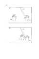
図12から図14を参照して、仮想空間2における片手操作モードと両手操作モードとの入力操作について説明する。図12は、ユーザがある局面に従う仮想空間2において認識する視野画像1210の変化を表す図である。 With reference to FIGS. 12 to 14, input operations in the one-handed operation mode and the two-handed operation mode in the
図12の状態(A)に示されるように、HMD装置110を装着したユーザがコントローラ160を操作すると、左手オブジェクト1220と右手オブジェクト1230とが仮想空間2に配置される。この状態で、ユーザが、打具オブジェクト1250を把持するための操作をコントローラ160に対して行うと、図12の状態(A)の例では右手オブジェクト1230と打具オブジェクト1250とが関連づけられて、ユーザの右手の動きと連動して右手オブジェクト1230と打具オブジェクト1250とが仮想空間2において移動する。ユーザは右手を動かすことで打具オブジェクト1250を移動させ、これにより、打具オブジェクト1250と、ボールなどの打撃対象物となる対象物オブジェクトとを衝突させることができる。状態(A)の例では、ユーザの右手と左手との位置関係に基づき、プロセッサ10は、片手操作モードとしてユーザの入力操作を受け付ける。 As shown in the state (A) of FIG. 12, when the user wearing the
図12の状態(B)に示されるように、ユーザの右手と左手との位置関係に基づき、プロセッサ10が両手操作モードを検知した場合、左手オブジェクト1220と右手オブジェクト1230と打具オブジェクト1250とが関連づけられて、ユーザの両手の動きと連動して左手オブジェクト1220と右手オブジェクト1230と打具オブジェクト1250とが移動する。プロセッサ10は、例えば対象物オブジェクトと打具オブジェクトとの衝突を検知した場合に、両手操作モードとしてユーザの入力操作を受け付ける。例えば、打具オブジェクト1250が斧やこん棒などの棒状の部材であれば、片手操作モードよりも両手操作モードの方が、対象物オブジェクトと衝突させた際に、対象物オブジェクトに対してより大きな作用を及ぼすよう処理する。 As shown in the state (B) of FIG. 12, when the
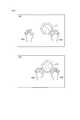
図13は、ユーザがある局面に従う仮想空間2において認識する視野画像1210の変化を示す図である。 FIG. 13 is a diagram illustrating a change in the visual field image 1210 recognized in the
図13の状態(A)に示されるように、ユーザが投擲対象物としてボールオブジェクト1260を把持するための操作をコントローラ160に対して行うと、図13の状態(A)の例では右手オブジェクト1230とボールオブジェクト1260とが関連付けられて、ユーザの右手の動きと連動して右手オブジェクト1230とボールオブジェクト1250とが仮想空間2において移動する。ユーザは右手を動かすとともに、右手オブジェクト1230とボールオブジェクト1260との関連付けを解除する入力操作を行うことで、ボールオブジェクト1260を投擲することができる。このときのボールオブジェクト1260の軌道は、例えば物理演算により求められる。状態(A)の例では、ユーザの右手と左手との位置関係に基づき、プロセッサ10は、片手操作モードとしてユーザの入力操作を受け付ける。 As shown in the state (A) of FIG. 13, when the user performs an operation for gripping the
図13の状態(B)に示されるように、ユーザの右手と左手との位置関係に基づき、プロセッサ10が両手操作モードを検知した場合、左手オブジェクト1220と右手オブジェクト1230とボールオブジェクト1260とが関連づけられて、ユーザの両手の動きと連動して左手オブジェクト1220と右手オブジェクト1230とボールオブジェクト1260とが移動する。ユーザは、右手オブジェクト1230および左手オブジェクト1220と、ボールオブジェクト1260との関連付けを解除する入力操作を受け付けて、ボールオブジェクト1260を投擲することができる。例えば、片手操作モードと両手操作モードとで、ボールオブジェクト1260に与えられる回転量を異ならせる等することができる。また、ボールオブジェクト1260が重量物を示すオブジェクトである場合、片手操作モードではボールオブジェクト1260と、左手オブジェクト1220または右手オブジェクト1230とを関連づけないこととして、ユーザが両手でないとボールオブジェクト1260を把持できないようにしてもよい。 As shown in the state (B) of FIG. 13, when the
図14は、ユーザがある局面に従う仮想空間2において認識する視野画像1210の変化を示す図である。 FIG. 14 is a diagram illustrating a change in the visual field image 1210 recognized in the
図14の状態(A)に示されるように、ユーザが手で把持する対象として、ハンドルオブジェクト1270を把持するための操作をコントローラ160に対して行うと、図14の状態(A)の例では右手オブジェクト1230とハンドルオブジェクト1270とが関連付けられる。ここで、ハンドルオブジェクト1270を、例えば扉を開閉するためのハンドル部材と見立て、片手ではハンドル部材を回転させることが困難であると見立てた場合、片手操作モードでは、ユーザの右手の動きにかかわらずハンドルオブジェクト1270が移動しない。状態(A)の例では、ユーザの右手と左手との位置関係に基づき、プロセッサ10は、片手操作モードとしてユーザの入力操作を受け付ける。 As shown in the state (A) of FIG. 14, when an operation for gripping the
図14の状態(B)に示されるように、ユーザの右手と左手との位置関係に基づき、プロセッサ10が両手操作モードを検知した場合、左手オブジェクト1220と右手オブジェクト1230とハンドルオブジェクト1270とが関連づけられて、ユーザの両手の動きと連動してハンドルオブジェクト1270を回転させられることとしてもよい。 As shown in the state (B) of FIG. 14, when the
これにより、ユーザは、仮想空間2において、片手での入力操作と、両手をあわせるような入力操作とを切り分けることができ、より仮想区間2における体験を多様化しうる。 As a result, the user can separate the input operation with one hand from the input operation in which both hands are combined in the
以上より、本明細書に開示された主題は、例えば、以下のような構成として示される。 From the above, the subject matter disclosed in the present specification is shown as the following configuration, for example.
[構成1] [Configuration 1]
ある実施の形態に従うと、コンピュータ(200)がヘッドマウントデバイス(HMD装置110)の表示内容を制御するための方法が提供される。この方法は、コンピュータ(200)のプロセッサ(10)が、ユーザの右手の状態および左手の状態を検出するように構成された検出ユニット(120、130)の検出結果を取得するステップと、プロセッサが、取得される検出ユニットの検出結果に基づいて、ユーザの入力操作を受け付けるステップと、プロセッサが、入力操作に応じて表示画像を生成し、生成した表示画像をヘッドマウントデバイスに表示させるステップとを含み、受け付けるステップにおいて、プロセッサが、ユーザの右手の位置と左手の位置との位置関係に基づいて、両手操作モードと片手操作モードとを切り替え、両手操作モードと片手操作モードとで異なる入力操作を受け付ける。 According to an embodiment, a method is provided for a computer (200) to control the display content of a head mounted device (HMD device 110). The method comprises a processor (10) of a computer (200) obtaining detection results of a detection unit (120, 130) configured to detect a user's right hand state and left hand state; Receiving a user input operation based on the acquired detection result of the detection unit; and a step of generating a display image according to the input operation and causing the head mounted device to display the generated display image. In the receiving step, the processor switches between the two-handed operation mode and the one-handed operation mode based on the positional relationship between the right hand position and the left hand position of the user, and performs different input operations in the two-handed operation mode and the one-handed operation mode. Accept.
[構成2] 好ましくは、受け付けるステップにおいて、プロセッサが、ユーザの右手の位置と左手の位置との位置関係に基づいて、右手と左手とが一定距離以下にある場合に両手操作モードとして入力操作を受け付け、右手と左手とが一定距離以上離れている場合に片手操作モードとして入力操作を受け付けることを含むを含む。 [Configuration 2] Preferably, in the receiving step, the processor performs an input operation as a two-hand operation mode when the right hand and the left hand are within a certain distance or less based on the positional relationship between the position of the right hand and the left hand of the user. Including accepting an input operation as a one-handed operation mode when the right hand and the left hand are separated by a certain distance or more.
[構成3] 好ましくは、検出ユニットは、光学センサを含み、ユーザの右手の状態および左手の状態を、光学センサにより光学的に検出するように構成されている。受け付けるステップにおいて、プロセッサが、検出ユニットが光学的に検出する検出結果を取得することを含む。 [Configuration 3] Preferably, the detection unit includes an optical sensor, and is configured to optically detect the state of the right hand and the left hand of the user by the optical sensor. In the accepting step, the processor includes obtaining a detection result optically detected by the detection unit.
[構成4] 好ましくは、検出ユニットは、ユーザの右手に把持される第1のコントローラと、ユーザの左手に把持される第2のコントローラとを含み、第1のコントローラおよび第2のコントローラの少なくともいずれかは、他方のコントローラが接近していることを検知する機構を有するように構成されている。受け付けるステップにおいて、プロセッサが、検出ユニットにおいて第1のコントローラと第2のコントローラとが接近していることを検知する機構の検知結果に基づいて、両手操作モードと片手操作モードとを切り替えることを含む。 [Configuration 4] Preferably, the detection unit includes a first controller held by the user's right hand and a second controller held by the user's left hand, and includes at least one of the first controller and the second controller. One of them is configured to have a mechanism for detecting that the other controller is approaching. In the receiving step, the processor includes switching between the two-handed operation mode and the one-handed operation mode based on a detection result of a mechanism that detects that the first controller and the second controller are approaching in the detection unit. .
[構成5] 好ましくは、第1のコントローラと第2のコントローラとは、それぞれ磁性体を搭載している。検出ユニットは、第1および第2のコントローラに搭載される磁性体に基づいて、第1のコントローラと第2のコントローラとが接近していることを検知するように構成されている。 [Configuration 5] Preferably, each of the first controller and the second controller is mounted with a magnetic material. The detection unit is configured to detect that the first controller and the second controller are approaching based on a magnetic body mounted on the first and second controllers.
[構成6] 好ましくは、コンピュータのメモリにおいて、オブジェクトの情報として、右手を示す仮想右手オブジェクトと、左手を示す仮想左手オブジェクトと、打具を示す打具オブジェクトと、打具により打たれる打撃対象物を示す打撃対象物オブジェクトと、の各オブジェクトの情報を少なくとも記憶するように構成されている。表示させるステップにおいて、プロセッサが、両手操作モードに切り替えている場合に、仮想右手オブジェクトと、仮想左手オブジェクトとが打具オブジェクトに関連付けられるように表示画像を生成し、ユーザの右手の状態および左手の状態の検出結果に応じて、仮想右手オブジェクトと仮想左手オブジェクトと打具オブジェクトとを移動させ、打具オブジェクトと打撃対象物オブジェクトとが衝突したときに、打撃対象物オブジェクトに対し、両手操作モードにおける作用を及ぼすように表示画像を生成する。表示させるステップにおいて、プロセッサが、片手操作モードに切り替えている場合に、仮想右手オブジェクトまたは仮想左手オブジェクトのいずれかが打具オブジェクトに関連付けられるように表示画像を生成し、打具オブジェクトに関連付けられる仮想手に対応するユーザの手の状態の検出結果に応じて、仮想右手オブジェクトと仮想左手オブジェクトと打具オブジェクトとを移動させ、打具オブジェクトと打撃対象物オブジェクトとが衝突したときに、打撃対象物オブジェクトに対し、片手操作モードにおける作用を及ぼすように表示画像を生成することを含む。 [Configuration 6] Preferably, in the memory of the computer, as object information, a virtual right hand object indicating the right hand, a virtual left hand object indicating the left hand, a hitting object indicating the hitting tool, and a hit target hit by the hitting tool It is configured to store at least information on each object of a hitting object indicating an object. In the displaying step, when the processor is switched to the two-hand operation mode, a display image is generated so that the virtual right hand object and the virtual left hand object are associated with the hitting object, and the state of the user's right hand and the left hand The virtual right hand object, the virtual left hand object, and the hitting object are moved according to the detection result of the state, and when the hitting object and the hit target object collide, the hit target object is in the two-hand operation mode. A display image is generated so as to act. In the displaying step, when the processor is switched to the one-hand operation mode, a display image is generated so that either the virtual right hand object or the virtual left hand object is associated with the hitting object, and the virtual image associated with the hitting object is generated. When the virtual right hand object, the virtual left hand object, and the hitting object are moved according to the detection result of the user's hand corresponding to the hand and the hitting object and the hitting target object collide, the hitting target Generating a display image so as to exert an effect on the object in the one-handed operation mode.
[構成7] 好ましくは、コンピュータのメモリにおいて、オブジェクトの情報として、右手を示す仮想右手オブジェクトと、左手を示す仮想左手オブジェクトと、投擲される対象となる投擲対象物を示す投擲対象物オブジェクトと、の各オブジェクトの情報を少なくとも記憶するように構成されている。表示させるステップにおいて、プロセッサが、両手操作モードに切り替えている場合に、仮想右手オブジェクトと、仮想左手オブジェクトとが投擲対象物オブジェクトに関連付けられるように表示画像を生成し、ユーザの右手の状態および左手の状態の検出結果に応じて、仮想右手オブジェクトと仮想左手オブジェクトと投擲対象物オブジェクトとを移動させ、投擲対象物オブジェクトに対し、両手操作モードにおける作用を及ぼすように表示画像を生成する。表示させるステップにおいて、プロセッサが、片手操作モードに切り替えている場合に、仮想右手オブジェクトまたは仮想左手オブジェクトのいずれかが投擲対象物オブジェクトに関連付けられるように表示画像を生成し、投擲対象物オブジェクトに関連付けられる仮想手に対応するユーザの手の状態の検出結果に応じて、仮想右手オブジェクトまたは仮想左手オブジェクトと投擲対象物オブジェクトとを移動させ、投擲対象物オブジェクトに対し、片手操作モードにおける作用を及ぼすように表示画像を生成することを含む。 [Configuration 7] Preferably, in the computer memory, as object information, a virtual right hand object indicating a right hand, a virtual left hand object indicating a left hand, a throwing target object indicating a throwing target to be thrown, The information of each object is stored at least. In the step of displaying, when the processor is switched to the two-handed operation mode, a display image is generated so that the virtual right hand object and the virtual left hand object are associated with the throwing target object, and the state of the user's right hand and the left hand The virtual right hand object, the virtual left hand object, and the throwing target object are moved according to the detection result of the state, and a display image is generated so that the throwing target object has an effect in the two-hand operation mode. In the displaying step, when the processor is switched to the one-handed operation mode, a display image is generated so that either the virtual right-hand object or the virtual left-hand object is associated with the throwing target object, and is associated with the throwing target object. The virtual right-hand object or the virtual left-hand object and the throwing target object are moved according to the detection result of the user's hand state corresponding to the virtual hand, and the throwing target object is affected in the one-hand operation mode. Generating a display image.
[構成8] 好ましくは、コンピュータのメモリにおいて、オブジェクトの情報として、右手を示す仮想右手オブジェクトと、左手を示す仮想左手オブジェクトと、仮想手により作用が与えられる対象となる重量物オブジェクトと、の各オブジェクトの情報を少なくとも記憶するように構成されている。受け付けるステップにおいて、プロセッサが、両手操作モードに切り替えている場合に、仮想右手オブジェクトと仮想左手オブジェクトとが重量物オブジェクトに関連付けられることにより、両手操作モードにおける作用を重量物オブジェクトに及ぼすように表示画像を生成する。表示させるステップにおいて、プロセッサが、片手操作モードに切り替えている場合に、仮想右手オブジェクトまたは仮想左手オブジェクトのいずれかが重量物オブジェクトに関連付けられることにより、片手操作モードにおける作用を重量物オブジェクトに及ぼすように表示画像を生成することを含む。 [Configuration 8] Preferably, in the memory of the computer, as the object information, each of a virtual right hand object indicating the right hand, a virtual left hand object indicating the left hand, and a heavy object to be acted on by the virtual hand It is configured to store at least object information. In the receiving step, when the processor is switched to the two-handed operation mode, the virtual right-hand object and the virtual left-hand object are associated with the heavy object so that the action in the two-handed operation mode is exerted on the heavy object. Is generated. In the displaying step, when the processor is switched to the one-handed operation mode, the virtual right-hand object or the virtual left-hand object is associated with the heavy object so that the effect in the one-handed operation mode is exerted on the heavy object. Generating a display image.
[構成9] 他の実施の形態に従うと、上記のいずれかの構成に記載の方法を一つ以上のコンピュータに実行させるプログラムが提供される。一つ以上のコンピュータは、インターネットを介して相互に通信可能な複数のコンピュータを含む。 [Configuration 9] According to another embodiment, there is provided a program that causes one or more computers to execute the method described in any of the above configurations. The one or more computers include a plurality of computers that can communicate with each other via the Internet.
[構成10] さらに他の実施の形態に従うと、仮想空間において入力を支援するための装置が提供される。この装置は、上記のプログラムを格納したメモリと、当該メモリに結合され、プログラムを実行するためのプロセッサとを備える。 [Configuration 10] According to still another embodiment, an apparatus for supporting input in a virtual space is provided. The apparatus includes a memory that stores the program and a processor that is coupled to the memory and executes the program.
具体的には、仮想体験をユーザに提供するためにヘッドマウントデバイスの表示内容を制御するためのシステムが提供される。このシステムは、ユーザの右手の状態および左手の状態を検出するように構成された検出ユニットと、ヘッドマウントデバイスおよび検出ユニットに接続可能なコンピュータを備える。コンピュータは、命令を格納するためのメモリと、メモリに電気的に接続されるプロセッサとを備える。プロセッサは、メモリに格納される命令を読みだして実行することにより、検出ユニットの検出結果を取得し、取得される検出ユニットの検出結果に基づいて、ユーザの入力操作を受け付け、入力操作に応じて表示画像を生成し、生成した表示画像をヘッドマウントデバイスに表示させ、ユーザの右手の位置と左手の位置との位置関係に基づいて、両手操作モードと片手操作モードとを切り替え、両手操作モードと片手操作モードとで異なる入力操作を受け付けるように構成されている。 Specifically, a system is provided for controlling the display content of a head mounted device in order to provide a virtual experience to a user. The system includes a detection unit configured to detect a user's right hand state and left hand state, and a head mount device and a computer connectable to the detection unit. The computer includes a memory for storing instructions and a processor electrically connected to the memory. The processor reads and executes an instruction stored in the memory to obtain a detection result of the detection unit, accepts a user input operation based on the acquired detection result of the detection unit, and responds to the input operation Display the generated display image on the head-mounted device, and switch between the two-handed operation mode and the one-handed operation mode based on the positional relationship between the right hand position and the left hand position of the user. And one-handed operation mode are configured to accept different input operations.
今回開示された実施の形態はすべての点で例示であって制限的なものではないと考えられるべきである。本発明の範囲は上記した説明ではなくて特許請求の範囲によって示され、特許請求の範囲と均等の意味および範囲内でのすべての変更が含まれることが意図される。 The embodiment disclosed this time should be considered as illustrative in all points and not restrictive. The scope of the present invention is defined by the terms of the claims, rather than the description above, and is intended to include any modifications within the scope and meaning equivalent to the terms of the claims.
1 仮想カメラ、2 仮想空間、5 基準視線、10 プロセッサ、11 メモリ、12 ストレージ、13 入出力インターフェイス、14 通信インターフェイス、15 バス、19 ネットワーク、21 中心、22 仮想空間画像、23 視界領域、24,25 領域、26 視界画像、31 フレーム、32 天面、33,34,36,37 ボタン、35 赤外線LED、38 アナログスティック、100 HMDシステム、110 HMD装置、112 モニタ、114,120 センサ、130 モーションセンサ、140 注視センサ、150 サーバ、160 コントローラ、190 ユーザ、200 コンピュータ、220 表示制御モジュール、221 仮想カメラ制御モジュール、222 視界領域決定モジュール、223 視界画像生成モジュール、224 基準視線特定モジュール、230 仮想空間制御モジュール、231 仮想空間定義モジュール、232 仮想オブジェクト生成モジュール、233 操作オブジェクト制御モジュール、234 入力装置オブジェクト制御モジュール、240 メモリモジュール、241 空間情報、242 オブジェクト情報、243 ユーザ情報、250 通信制御モジュール、800 右コントローラ、810 右手、1210 視野画像、1220 左手オブジェクト、1230 右手オブジェクト、1410 左手。 1 virtual camera, 2 virtual space, 5 reference line of sight, 10 processor, 11 memory, 12 storage, 13 input / output interface, 14 communication interface, 15 bus, 19 network, 21 center, 22 virtual space image, 23 viewing area, 24, 25 area, 26 field of view image, 31 frame, 32 top surface, 33, 34, 36, 37 button, 35 infrared LED, 38 analog stick, 100 HMD system, 110 HMD device, 112 monitor, 114, 120 sensor, 130 motion sensor , 140 gaze sensor, 150 server, 160 controller, 190 user, 200 computer, 220 display control module, 221 virtual camera control module, 222 view area determination module, 223 view image Creation module, 224 reference gaze identification module, 230 virtual space control module, 231 virtual space definition module, 232 virtual object generation module, 233 operation object control module, 234 input device object control module, 240 memory module, 241 space information, 242 object Information, 243 User information, 250 Communication control module, 800 Right controller, 810 Right hand, 1210 Field of view image, 1220 Left hand object, 1230 Right hand object, 1410 Left hand.
Claims (10)
Translated fromJapanese前記コンピュータのプロセッサが、ユーザの右手の状態および左手の状態を検出するように構成された検出ユニットの検出結果を取得するステップと、
前記プロセッサが、前記取得される前記検出ユニットの検出結果に基づいて、ユーザの入力操作を受け付けるステップと、
前記プロセッサが、前記入力操作に応じて表示画像を生成し、生成した表示画像を前記ヘッドマウントデバイスに表示させるステップとを含み、
前記受け付けるステップにおいて、前記プロセッサが、前記ユーザの前記右手の位置と前記左手の位置との位置関係に基づいて、両手操作モードと片手操作モードとを切り替え、前記両手操作モードと前記片手操作モードとで異なる入力操作を受け付けることを含む、方法。A method for a computer to control the display content of a head mounted device,
Obtaining a detection result of a detection unit configured to detect a right hand state and a left hand state of the user by a processor of the computer;
The processor accepting a user input operation based on the acquired detection result of the detection unit;
The processor generating a display image in response to the input operation, and displaying the generated display image on the head mounted device,
In the receiving step, the processor switches between a two-hand operation mode and a one-hand operation mode based on a positional relationship between the right hand position and the left hand position of the user, and the two-hand operation mode and the one-hand operation mode Accepting different input operations at a method.
前記受け付けるステップにおいて、前記プロセッサが、前記検出ユニットが光学的に検出する検出結果を取得することを含む、請求項2に記載の方法。The detection unit includes an optical sensor, and is configured to optically detect the state of the right hand and the state of the left hand of the user by the optical sensor,
The method according to claim 2, wherein in the receiving step, the processor includes obtaining a detection result detected optically by the detection unit.
前記受け付けるステップにおいて、前記プロセッサが、前記検出ユニットにおいて前記第1のコントローラと前記第2のコントローラとが接近していることを検知する機構の検知結果に基づいて、前記両手操作モードと前記片手操作モードとを切り替えることを含む、請求項2に記載の方法。The detection unit includes a first controller held by the right hand of the user and a second controller held by the left hand of the user, and at least one of the first controller and the second controller Is configured to have a mechanism for detecting that the other controller is approaching,
In the step of receiving, the two-handed operation mode and the one-handed operation are performed based on a detection result of a mechanism in which the processor detects that the first controller and the second controller are approaching in the detection unit. The method of claim 2, comprising switching between modes.
前記表示させるステップにおいて、前記プロセッサが、前記両手操作モードに切り替えている場合に、前記仮想右手オブジェクトと、前記仮想左手オブジェクトとが前記打具オブジェクトに関連付けられるように前記表示画像を生成し、前記ユーザの右手の状態および左手の状態の検出結果に応じて、前記仮想右手オブジェクトと前記仮想左手オブジェクトと前記打具オブジェクトとを移動させ、前記打具オブジェクトと前記打撃対象物オブジェクトとが衝突したときに、前記打撃対象物オブジェクトに対し、前記両手操作モードにおける作用を及ぼすように前記表示画像を生成し、
前記表示させるステップにおいて、前記プロセッサが、前記片手操作モードに切り替えている場合に、前記仮想右手オブジェクトまたは前記仮想左手オブジェクトのいずれかが前記打具オブジェクトに関連付けられるように前記表示画像を生成し、前記打具オブジェクトに関連付けられる仮想手に対応するユーザの手の状態の検出結果に応じて、前記仮想右手オブジェクトと前記仮想左手オブジェクトと前記打具オブジェクトとを移動させ、前記打具オブジェクトと前記打撃対象物オブジェクトとが衝突したときに、前記打撃対象物オブジェクトに対し、前記片手操作モードにおける作用を及ぼすように前記表示画像を生成することを含む、請求項2に記載の方法。In the computer memory, as object information, a virtual right hand object indicating a right hand, a virtual left hand object indicating a left hand, a hitting object indicating a hitting tool, and a hit target indicating a hit target hit by the hitting tool The object object is configured to store at least information of each object,
In the step of displaying, when the processor is switched to the two-hand operation mode, the display image is generated so that the virtual right hand object and the virtual left hand object are associated with the hitting object, When the virtual right hand object, the virtual left hand object, and the hitting object are moved according to the detection result of the right hand state and the left hand state of the user, and the hitting object and the hit object object collide And generating the display image so as to exert an action in the two-handed operation mode on the hitting object.
In the step of displaying, when the processor is switching to the one-handed operation mode, the display image is generated so that either the virtual right hand object or the virtual left hand object is associated with the hitting object, The virtual right hand object, the virtual left hand object, and the hitting object are moved according to a detection result of a user's hand state corresponding to the virtual hand associated with the hitting object, and the hitting object and the hitting object are moved. The method according to claim 2, further comprising generating the display image so as to exert an action in the one-handed operation mode on the hitting target object when the target object collides.
前記表示させるステップにおいて、前記プロセッサが、前記両手操作モードに切り替えている場合に、前記仮想右手オブジェクトと、前記仮想左手オブジェクトとが前記投擲対象物オブジェクトに関連付けられるように前記表示画像を生成し、前記ユーザの右手の状態および左手の状態の検出結果に応じて、前記仮想右手オブジェクトと前記仮想左手オブジェクトと前記投擲対象物オブジェクトとを移動させ、前記投擲対象物オブジェクトに対し、前記両手操作モードにおける作用を及ぼすように前記表示画像を生成し、
前記表示させるステップにおいて、前記プロセッサが、前記片手操作モードに切り替えている場合に、前記仮想右手オブジェクトまたは前記仮想左手オブジェクトのいずれかが前記投擲対象物オブジェクトに関連付けられるように前記表示画像を生成し、前記投擲対象物オブジェクトに関連付けられる仮想手に対応するユーザの手の状態の検出結果に応じて、前記仮想右手オブジェクトまたは前記仮想左手オブジェクトと前記投擲対象物オブジェクトとを移動させ、前記投擲対象物オブジェクトに対し、前記片手操作モードにおける作用を及ぼすように前記表示画像を生成することを含む、請求項2に記載の方法。In the memory of the computer, as object information, information on each of a virtual right hand object indicating a right hand, a virtual left hand object indicating a left hand, and a throwing target object indicating a throwing target object to be thrown. Configured to remember at least,
In the step of displaying, when the processor is switched to the two-hand operation mode, the display image is generated so that the virtual right hand object and the virtual left hand object are associated with the throwing target object, The virtual right hand object, the virtual left hand object, and the throwing target object are moved according to the detection result of the user's right hand state and left hand state, and the throwing target object is moved in the two-hand operation mode. Generating the display image to act,
In the step of displaying, when the processor is switched to the one-hand operation mode, the display image is generated so that either the virtual right hand object or the virtual left hand object is associated with the throwing target object. The virtual right hand object or the virtual left hand object and the throwing target object are moved according to the detection result of the state of the user's hand corresponding to the virtual hand associated with the throwing target object, and the throwing target object The method according to claim 2, comprising generating the display image to exert an effect on the object in the one-handed operation mode.
前記受け付けるステップにおいて、前記プロセッサが、前記両手操作モードに切り替えている場合に、前記仮想右手オブジェクトと前記仮想左手オブジェクトとが前記重量物オブジェクトに関連付けられることにより、前記両手操作モードにおける作用を前記重量物オブジェクトに及ぼすように前記表示画像を生成し、
前記表示させるステップにおいて、前記プロセッサが、前記片手操作モードに切り替えている場合に、前記仮想右手オブジェクトまたは前記仮想左手オブジェクトのいずれかが前記重量物オブジェクトに関連付けられることにより、前記片手操作モードにおける作用を前記重量物オブジェクトに及ぼすように前記表示画像を生成することを含む、請求項2に記載の方法。In the memory of the computer, as object information, at least information on each object of a virtual right hand object indicating the right hand, a virtual left hand object indicating the left hand, and a heavy object to be acted on by the virtual hand is stored. Is configured to
In the accepting step, when the processor is switching to the two-handed operation mode, the virtual right-hand object and the virtual left-hand object are associated with the heavy object, so that the action in the two-handed operation mode can be performed. Generate the display image to affect the object,
In the displaying step, when the processor is switched to the one-handed operation mode, the virtual right-hand object or the virtual left-hand object is associated with the heavy object, whereby the operation in the one-handed operation mode is performed. The method of claim 2, comprising generating the display image to affect the heavy object.
ユーザの右手の状態および左手の状態を検出するように構成された検出ユニットと、
前記ヘッドマウントデバイスおよび前記検出ユニットに接続可能なコンピュータを備え、
前記コンピュータは、
命令を格納するためのメモリと、
前記メモリに電気的に接続されるプロセッサとを備えており、
前記プロセッサは、前記メモリに格納される前記命令を読みだして実行することにより、
前記検出ユニットの検出結果を取得し、
前記取得される前記検出ユニットの検出結果に基づいて、ユーザの入力操作を受け付け、
前記入力操作に応じて表示画像を生成し、生成した表示画像を前記ヘッドマウントデバイスに表示させ、
前記ユーザの前記右手の位置と前記左手の位置との位置関係に基づいて、両手操作モードと片手操作モードとを切り替え、前記両手操作モードと前記片手操作モードとで異なる入力操作を受け付けるように構成されている、システム。A system for controlling the display content of a head mounted device to provide a virtual experience to a user,
A detection unit configured to detect a user's right hand state and left hand state;
A computer connectable to the head mounted device and the detection unit;
The computer
Memory for storing instructions;
A processor electrically connected to the memory,
The processor reads and executes the instructions stored in the memory,
Obtaining a detection result of the detection unit;
Based on the obtained detection result of the detection unit, accepting a user input operation,
A display image is generated according to the input operation, and the generated display image is displayed on the head mounted device.
The two-handed operation mode and the one-handed operation mode are switched based on the positional relationship between the right hand position and the left hand position of the user, and different input operations are accepted between the two-handed operation mode and the one-handed operation mode. Being the system.
Priority Applications (1)
| Application Number | Priority Date | Filing Date | Title |
|---|---|---|---|
| JP2016165158AJP6174215B1 (en) | 2016-08-25 | 2016-08-25 | Method and system for controlling display contents of head mounted device, and program for causing computer to execute the method |
Applications Claiming Priority (1)
| Application Number | Priority Date | Filing Date | Title |
|---|---|---|---|
| JP2016165158AJP6174215B1 (en) | 2016-08-25 | 2016-08-25 | Method and system for controlling display contents of head mounted device, and program for causing computer to execute the method |
Related Child Applications (1)
| Application Number | Title | Priority Date | Filing Date |
|---|---|---|---|
| JP2017061984ADivisionJP2018032373A (en) | 2017-03-27 | 2017-03-27 | Method and system of controlling display content of head-mounted device and program of causing computer to execute the method |
Publications (2)
| Publication Number | Publication Date |
|---|---|
| JP6174215B1 JP6174215B1 (en) | 2017-08-02 |
| JP2018032274Atrue JP2018032274A (en) | 2018-03-01 |
Family
ID=59505264
Family Applications (1)
| Application Number | Title | Priority Date | Filing Date |
|---|---|---|---|
| JP2016165158AActiveJP6174215B1 (en) | 2016-08-25 | 2016-08-25 | Method and system for controlling display contents of head mounted device, and program for causing computer to execute the method |
Country Status (1)
| Country | Link |
|---|---|
| JP (1) | JP6174215B1 (en) |
Cited By (1)
| Publication number | Priority date | Publication date | Assignee | Title |
|---|---|---|---|---|
| KR20200110103A (en)* | 2019-03-14 | 2020-09-23 | 주식회사 듀코젠 | Method and system for authoring virtual reality contents with two hands motion input |
Families Citing this family (1)
| Publication number | Priority date | Publication date | Assignee | Title |
|---|---|---|---|---|
| US10809910B2 (en)* | 2018-09-28 | 2020-10-20 | Apple Inc. | Remote touch detection enabled by peripheral device |
Citations (4)
| Publication number | Priority date | Publication date | Assignee | Title |
|---|---|---|---|---|
| JP2014021528A (en)* | 2012-07-12 | 2014-02-03 | Nec Casio Mobile Communications Ltd | Information processing device, display control method, and program |
| JP2014199493A (en)* | 2013-03-29 | 2014-10-23 | 株式会社ジャパンディスプレイ | Electronic device and method for controlling electronic device |
| JP2015060494A (en)* | 2013-09-20 | 2015-03-30 | カシオ計算機株式会社 | Portable terminal device and program |
| US20150258431A1 (en)* | 2014-03-14 | 2015-09-17 | Sony Computer Entertainment Inc. | Gaming device with rotatably placed cameras |
- 2016
- 2016-08-25JPJP2016165158Apatent/JP6174215B1/enactiveActive
Patent Citations (4)
| Publication number | Priority date | Publication date | Assignee | Title |
|---|---|---|---|---|
| JP2014021528A (en)* | 2012-07-12 | 2014-02-03 | Nec Casio Mobile Communications Ltd | Information processing device, display control method, and program |
| JP2014199493A (en)* | 2013-03-29 | 2014-10-23 | 株式会社ジャパンディスプレイ | Electronic device and method for controlling electronic device |
| JP2015060494A (en)* | 2013-09-20 | 2015-03-30 | カシオ計算機株式会社 | Portable terminal device and program |
| US20150258431A1 (en)* | 2014-03-14 | 2015-09-17 | Sony Computer Entertainment Inc. | Gaming device with rotatably placed cameras |
Cited By (2)
| Publication number | Priority date | Publication date | Assignee | Title |
|---|---|---|---|---|
| KR20200110103A (en)* | 2019-03-14 | 2020-09-23 | 주식회사 듀코젠 | Method and system for authoring virtual reality contents with two hands motion input |
| KR102181499B1 (en) | 2019-03-14 | 2020-11-23 | 주식회사 듀코젠 | Method and system for authoring virtual reality contents with two hands motion input |
Also Published As
| Publication number | Publication date |
|---|---|
| JP6174215B1 (en) | 2017-08-02 |
Similar Documents
| Publication | Publication Date | Title |
|---|---|---|
| JP6470796B2 (en) | Information processing method, program, and computer | |
| JP6509955B2 (en) | INFORMATION PROCESSING METHOD, PROGRAM, AND INFORMATION PROCESSING DEVICE | |
| JP6368411B1 (en) | Method, program and computer executed on a computer to provide a virtual experience | |
| JP6248219B1 (en) | Information processing method, computer, and program for causing computer to execute information processing method | |
| JP6479933B1 (en) | Program, information processing apparatus, and method | |
| JP6368404B1 (en) | Information processing method, program, and computer | |
| JP6278546B1 (en) | Information processing method, apparatus, and program for causing computer to execute information processing method | |
| JP6965304B2 (en) | Programs, information processing devices, and information processing methods | |
| JP2018175849A (en) | Information processing method, apparatus, and program for causing a computer to execute the information processing method | |
| JP6174215B1 (en) | Method and system for controlling display contents of head mounted device, and program for causing computer to execute the method | |
| JP2019087262A (en) | Program, information processing apparatus, and method | |
| JP6495398B2 (en) | Method and program for providing virtual space, and information processing apparatus for executing the program | |
| JP6535641B2 (en) | Method and apparatus for controlling an object displayed in a virtual space, and program for causing a computer to execute the method | |
| JP6457446B2 (en) | Method and apparatus for supporting communication in virtual space, and program for causing computer to execute the method | |
| JP2019020832A (en) | Information processing method, apparatus, and program for causing computer to execute information processing method | |
| JP2019020836A (en) | Information processing method, device, and program for causing computer to execute the method | |
| JP2018032383A (en) | Method and apparatus for supporting input in virtual space, and program for causing computer to execute the method | |
| JP6458179B1 (en) | Program, information processing apparatus, and method | |
| JP6298557B1 (en) | Information processing method, apparatus, and program for causing computer to execute information processing method | |
| JP2018032373A (en) | Method and system of controlling display content of head-mounted device and program of causing computer to execute the method | |
| JP2018067297A (en) | Information processing method, apparatus, and program for causing computer to execute information processing method | |
| JP2018206353A (en) | Information processing method, apparatus, and program for implementing that information processing method in computer | |
| JP2019083028A (en) | Information processing method, program, and computer | |
| JP2018101293A (en) | Method executed by computer to provide virtual space to head mounted device, program causing computer to execute the method, and computer apparatus | |
| JP2018032130A (en) | Method and device for supporting input in virtual space and program causing computer to execute the method |
Legal Events
| Date | Code | Title | Description |
|---|---|---|---|
| TRDD | Decision of grant or rejection written | ||
| A01 | Written decision to grant a patent or to grant a registration (utility model) | Free format text:JAPANESE INTERMEDIATE CODE: A01 Effective date:20170609 | |
| A61 | First payment of annual fees (during grant procedure) | Free format text:JAPANESE INTERMEDIATE CODE: A61 Effective date:20170705 | |
| R150 | Certificate of patent or registration of utility model | Ref document number:6174215 Country of ref document:JP Free format text:JAPANESE INTERMEDIATE CODE: R150 | |
| R250 | Receipt of annual fees | Free format text:JAPANESE INTERMEDIATE CODE: R250 | |
| R250 | Receipt of annual fees | Free format text:JAPANESE INTERMEDIATE CODE: R250 |