JP2018017681A - Inspection tool - Google Patents
Inspection toolDownload PDFInfo
- Publication number
- JP2018017681A JP2018017681AJP2016150026AJP2016150026AJP2018017681AJP 2018017681 AJP2018017681 AJP 2018017681AJP 2016150026 AJP2016150026 AJP 2016150026AJP 2016150026 AJP2016150026 AJP 2016150026AJP 2018017681 AJP2018017681 AJP 2018017681A
- Authority
- JP
- Japan
- Prior art keywords
- inspection
- base material
- connecting member
- inspection tool
- test
- Prior art date
- Legal status (The legal status is an assumption and is not a legal conclusion. Google has not performed a legal analysis and makes no representation as to the accuracy of the status listed.)
- Granted
Links
Images


Landscapes
- Investigating Or Analysing Biological Materials (AREA)
Abstract
Translated fromJapaneseDescription
Translated fromJapanese本発明は、イムノクロマトグラフィー法又は核酸クロマトグラフィー法に用いられる検査具に関する。 The present invention relates to a test tool used in an immunochromatography method or a nucleic acid chromatography method.
従来から、イムノクロマトグラフィー法又は核酸クロマトグラフィー法には、標的物質を検出する検出部を備えたストリップ状の検査体が用いられている。検査体は、例えば、標的物質を含む被検液(試料液体)が溜められた容器に挿入されることで、被検液を毛細管現象により吸収し、標的物質を検出する。 Conventionally, in the immunochromatography method or the nucleic acid chromatography method, a strip-shaped test body having a detection unit for detecting a target substance has been used. The test body, for example, is inserted into a container in which a test liquid (sample liquid) containing the target substance is stored, thereby absorbing the test liquid by capillary action and detecting the target substance.
検査体による検査は、例えば、ウェルプレートに一列に配置された複数のチューブ内の被検液に対して実施されることがある。この場合、検査体を各チューブに1本ずつ挿入する必要があるため、作業性がよくない。また、チューブに挿入した検査体がチューブ内で回転することがあり、検査結果が見難くなるといった問題も生じ得る。そこで、例えば、特許文献1に記載された検査具が知られている。特許文献1に記載の検査具は、標的物質を検出する検出部(第2の領域)を有する複数の検査体(フィンガ)が連結部材で連結されている。特許文献1に記載の検査具では、連結部材は、各検査体において、被検液に浸漬される端部とは反対側の端部に設けられている。 The inspection by the inspection body may be performed on the test liquid in a plurality of tubes arranged in a row on the well plate, for example. In this case, since it is necessary to insert one test body into each tube, workability is not good. Moreover, the test body inserted in the tube may rotate in the tube, and there may be a problem that the test result becomes difficult to see. Therefore, for example, an inspection tool described in
上記のように、従来の検査具では、連結部材が、被検液に浸漬される端部とは反対側の端部に設けられる。検査体は、一般的に、プラスチック等からなるシート状の基材に検出部が配置されている。この構成では、被検液が溜まっている容器に各検査体を挿入するときに、基材が撓むことがある。これにより、従来の検査具では、一列に並設された容器に検査体を挿入するときに、検査体の端部の位置がずれることがある。これにより、作業効率が低下するおそれがある。 As described above, in the conventional inspection tool, the connecting member is provided at the end opposite to the end immersed in the test solution. In general, the inspection body includes a detection unit disposed on a sheet-like base material made of plastic or the like. In this configuration, the base material may bend when each test object is inserted into the container in which the test liquid is accumulated. Thereby, in the conventional test | inspection tool, when inserting a test body into the container arranged in parallel, the position of the edge part of a test body may shift | deviate. Thereby, there exists a possibility that work efficiency may fall.
本発明の一側面は、複数の検査体を容器に対してスムーズに挿入できる検査具を提供することを目的とする。 An object of one aspect of the present invention is to provide an inspection tool capable of smoothly inserting a plurality of inspection objects into a container.
上記課題を解決するための手段として本明細書では以下の発明を開示する。
(1)一方向に延在する基材と、基材の一面に配置され、被検液を展開すると共に当該被検液に含まれる標的物質を検出して表示する検出部と、基材の一面において検出部における展開方向の終端部側に配置され、被検液を吸収する吸収部と、をそれぞれ有する複数の検査体と、一方向に直交する他方向において複数の検査体が所定の間隔をあけて配置されるように、複数の検査体を連結する連結部材と、を備え、連結部材の少なくとも一部は、検出部における展開方向の始端部側に位置する基材の端部と、基材の一方向における中央部との間の範囲内に設けられている、検査具。As means for solving the above problems, the present invention discloses the following invention.
(1) A base material extending in one direction, a detection unit that is disposed on one surface of the base material and that develops a test liquid and detects and displays a target substance contained in the test liquid; A plurality of test bodies each having an absorption section that absorbs the test liquid and is disposed on the end side in the development direction of the detection section on one surface, and a plurality of test bodies in a different direction orthogonal to the one direction at a predetermined interval A connecting member that connects a plurality of test bodies so as to be opened, and at least a part of the connecting member is an end portion of the base material that is located on the start end side in the deployment direction of the detection unit; The inspection tool provided in the range between the center part in one direction of a base material.
(2)検査体は、基材の一面において上記始端部側に配置され、被検液を採取する採取部を有し、検出部は、採取部と吸収部との間に配置されている、(1)に記載の検査具。(2) The test body is disposed on the starting end side on one surface of the base material, and has a collection unit that collects the test liquid, and the detection unit is disposed between the collection unit and the absorption unit. The inspection tool according to (1).
(3)検査体は、基材の一面において採取部と検出部との間に配置され、被検液の標的物質と反応する標識物を保持する試薬保持部を備える、(2)に記載の検査具。(3) The test body is provided between the collection unit and the detection unit on one surface of the substrate, and includes a reagent holding unit that holds a label that reacts with the target substance of the test solution. Inspection tool.
(4)上記終端部側に位置する連結部材の端部は、上記終端部側に位置する基材の端部に位置している、(1)〜(3)のいずれかに記載の検査具。(4) The inspection tool according to any one of (1) to (3), wherein an end portion of the connecting member positioned on the end portion side is positioned on an end portion of the base material positioned on the end portion side. .
(5)連結部材は、他方向に沿って延在しており、基材の一面とは反対側の他面に接合されている、(1)〜(4)のいずれかに記載の検査具。(5) The inspection tool according to any one of (1) to (4), wherein the connecting member extends along the other direction and is joined to the other surface opposite to the one surface of the base material. .
(6)複数の検査体それぞれの基材の一面は同じ方向を向いており、基材の一面に直交する方向は、一方向及び他方向と直交している、(5)に記載の検査具。(6) The inspection tool according to (5), wherein one surface of each of the plurality of inspection bodies faces the same direction, and a direction orthogonal to the one surface of the substrate is orthogonal to one direction and the other direction. .
(7)連結部材には、検出部の検出結果の視認性を補助する目盛が設けられている、(1)〜(6)のいずれかに記載の検査具。(7) The inspection tool according to any one of (1) to (6), wherein the connecting member is provided with a scale that assists the visibility of the detection result of the detection unit.
(8)連結部材には、一方向に沿って切れ目が設けられている、(1)〜(7)のいずれかに記載の検査具。(8) The inspection tool according to any one of (1) to (7), wherein the connection member is provided with a cut along one direction.
(9)連結部材は、撥水性を有している、(1)〜(8)のいずれかに記載の検査具。(9) The inspection tool according to any one of (1) to (8), wherein the connecting member has water repellency.
本発明の一側面によれば、複数の検査体を容器に対してスムーズに挿入できる。 According to one aspect of the present invention, a plurality of inspection objects can be smoothly inserted into a container.
以下、添付図面を参照して、本発明の好適な実施形態について詳細に説明する。なお、図面の説明において同一又は相当要素には同一符号を付し、重複する説明は省略する。 Hereinafter, preferred embodiments of the present invention will be described in detail with reference to the accompanying drawings. In the description of the drawings, the same or equivalent elements will be denoted by the same reference numerals, and redundant description will be omitted.
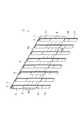
図1に示されるように、検査具1は、複数の検査体3と、連結部材5と、を備えている。本実施形態では、8個の検査体3を備える検査具1を一例として説明する。検査具1は、例えば、イムノクロマトグラフィー法、又は、核酸クロマトグラフィー法に用いられる。以下の説明では、各図に示すX方向及びY方向を説明に用いる場合もある。 As shown in FIG. 1, the
[検査体]
複数の検査体3のそれぞれは、同じ構成を有している。以下では、1つの検査体3を一例に具体的に説明する。検査体3は、バッキングシート(基材)7と、メンブレン(検出部)9と、吸収パッド(吸収部)11と、を備える。本実施形態では、検査体3は、図1〜図4に示されるように、バッキングシート(基材)7と、メンブレン(検出部)9と、吸収パッド(吸収部)11と、サンプルパッド(採取部)13と、コンジュゲートパッド(試薬保持部)15と、を備えている。検査体3では、被検液は、サンプルパッド13、コンジュゲートパッド15、メンブレン9及び吸収パッド11の順番で展開される(図5参照)。[Inspection body]
Each of the plurality of
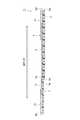
バッキングシート7は、メンブレン9、吸収パッド11、サンプルパッド13及びコンジュゲートパッド15を支持する。バッキングシート7は、一方向に延在する帯状の板部材である。バッキングシート7は、長手方向(一方向、Y方向)の寸法が幅方向(X方向)の寸法よりも大きい。図5に示されるように、バッキングシート7は、第1面(一面)7aと、第1面7aとは反対側の第2面(他面)7bと、を有する。バッキングシート7は、撥水性を有する。バッキングシート7は、撥水性を有する材料で形成されていてもよい。撥水性を有する材料としては、例えば、ポリエチレン、ポリスチレン、ポリプロピレン、塩化ビニル等が挙げられる。また、バッキングシート7は、その表面に撥水加工が施されていてもよい。バッキングシート7の長さL(図2参照)、幅及び厚さは、設計に応じて適宜設定される。後述するチューブC(図6参照)がPCRチューブである場合、バッキングシート7の幅は、例えば、1.5mm以上6.0mm以下であり、2.5mm以上4.0mm以下であることが好ましい。幅が1.5mm未満であると後述するテストライン9a〜9cの識別性が低下し、幅が6.0mmよりも大きいとPCRチューブに挿入できない。 The
メンブレン9は、被検液を展開すると共に被検液に含まれる標的物質を検出して表示する。標的物質は、例えば、核酸クロマトグラフィー法においては核酸であり、イムノクロマト法においてはタンパク質、脂質、糖質、核酸、金属イオン、薬剤等の低分子化合物等である。メンブレン9は、バッキングシート7の第1面7aに配置されている。図2に示されるように、メンブレン9には、複数(ここでは3個)のテストライン9a,9b,9cが設けられている。テストライン9a〜9cは、被検液の展開方向において、所定の間隔を開けて複数配置されている。テストライン9a〜9cは、標的物質と結合可能な物質(核酸、抗原、抗体等)が固相化されたものである。 The
メンブレン9としては、定性濾紙、定量濾紙、分液濾紙、硝子繊維濾紙、シリカ繊維濾紙、複合繊維濾紙等の濾紙が挙げられる。また、メンブレン9としては、ニトロセルロース等のセルロースの濾紙、ポリエーテルスルフォンメンブレン等の合成樹脂の膜、又は、シリカゲル、アガロース、デキストラン、ゼラチン等の多孔質ゲルも使用できる。また、メンブレン9としては、ナイロンメンブレンも使用できる。 Examples of the
吸収パッド11は、メンブレン9を展開した被検液を吸収する。吸収パッド11は、バッキングシート7の第1面7aに配置されている。吸収パッド11は、メンブレン9の展開方向における終端部側に配置されている。本実施形態では、吸収パッド11は、バッキングシート7の長手方向の一方(展開方向下流側)の端部8a側に配置されている。本実施形態では、図5に示されるように、吸収パッド11の展開方向における始端部側は、メンブレン9の終端部側と重なっている。吸収パッド11としては、例えば、定性濾紙、定量濾紙、分液濾紙、硝子繊維濾紙、シリカ繊維濾紙、複合繊維濾紙等の吸水性を有する濾紙が挙げられる。 The
サンプルパッド13は、被検液を採取する。サンプルパッド13は、バッキングシート7の第1面7aに配置されている。サンプルパッド13は、メンブレン9の展開方向の始端部側に位置している。本実施形態では、サンプルパッド13は、バッキングシート7の長手方向の他方(展開方向上流側)の端部8b側に配置されている。サンプルパッド13としては、例えば、定性濾紙、定量濾紙、分液濾紙、硝子繊維濾紙、シリカ繊維濾紙、複合繊維濾紙等の吸水性を有する濾紙が挙げられる。 The
コンジュゲートパッド15は、被検液の標的物質と反応する標識物を保持する。標識物は、例えば、着色担体である。着色担体は、例えば、着色粒子(コロイド粒子、着色ラテックス、シリカナノ粒子等)を用いることができる。コンジュゲートパッド15は、バッキングシート7の第1面7aに配置されている。コンジュゲートパッド15は、サンプルパッド13とメンブレン9との間に配置されている。本実施形態では、図5に示されるように、コンジュゲートパッド15の展開方向における始端部側は、サンプルパッド13の終端部側と重なっている。本実施形態では、コンジュゲートパッド15の終端部側は、メンブレン9の始端部側と重なっている。コンジュゲートパッド15としては、定性濾紙、定量濾紙、分液濾紙、硝子繊維濾紙、シリカ繊維濾紙、複合繊維濾紙等の濾紙が挙げられる。 The
[連結部材]
連結部材5は、複数(少なくとも2個以上)の検査体3を連結する。連結部材5は、バッキングシート7の長手方向(Y方向)に直交する他方向(X方向)において複数の検査体3が所定の間隔をあけて配置されるように、複数の検査体3を連結する。検査具1では、バッキングシート7の第1面7aに直交する方向は、バッキングシート7の長手方向及び上記他方向(複数の検査体3の配列方向)と直交している。なお、直交とは、略直交を含むものであり、例えば±3°程度の範囲を含み得る。連結部材5は、複数の検査体3を連結する部材であれば、どのような部材であってもよい。本実施形態では、連結部材5は、矩形状を呈する板部材である。連結部材5は、撥水性を有する材料で形成されている。連結部材5は、例えば、ポリエチレン、ポリスチレン、ポリプロピレン、塩化ビニル等により形成される。連結部材5の厚さは、設計に応じて適宜設定される。連結部材5の厚さは、例えば、1mm〜2mm程度である。[Connecting member]
The connecting
連結部材5は、バッキングシート7の第2面7bに、例えば接着剤により接合されている。連結部材5は、各検査体3のバッキングシート7の第1面7aが同じ方向を向くように、各検査体3を連結している。図2に示されるように、連結部材5は、隣り合う検査体3が所定の間隔Dを有して離間して配置されるように、各検査体3を連結している。間隔Dは、例えば、図6に示されるチューブCの配列間隔に応じて適宜設定される。間隔Dは、例えば、隣り合う検査体3の幅方向の中心間の距離が9mm程度となるように設定される。 The connecting
連結部材5の少なくとも一部は、メンブレン9における展開方向の始端部側に位置するバッキングシート7の端部8bと、バッキングシート7の長手方向における中央部との間の範囲内に設けられている。中央部は、図2に示されるように、バッキングシート7の長さL1の1/2の位置である。つまり、中央部とバッキングシート7の端部8bとの間の長さL2は、長さL1の1/2となる。 At least a part of the connecting
本実施形態では、連結部材5における展開方向下流側の端部5aは、バッキングシート7の端部8aに位置し、連結部材5における展開方向上流側の端部5bは、バッキングシート7の中央部よりも展開方向上流側に位置している。具体的には、連結部材5における展開方向上流側の端部5bは、コンジュゲートパッド15の展開方向の終端部に位置している。連結部材5は、コンジュゲートパッド15の展開方向の終端部から吸収パッド11の展開方向の終端部にわたって配置されている。図2に示されるように、連結部材5の長さL3は、長さL1よりも短く、且つ、長さL2より長い(L2<L3<L1)。 In the present embodiment, the
連結部材5の端部5bとバッキングシート7の端部8bとの間の長さは、被検液が溜められる容器に応じて適宜設定される。連結部材5の端部5bとバッキングシート7の端部8bとの間の長さが短すぎると、容器の上縁と連結部材5とが当接し、容器内に検査体3が十分に挿入されないおそれがある。この場合、検査具1が倒れ、容器から検査体3が抜ける可能性がある。そのため、連結部材5の端部5bとバッキングシート7の端部8bとの間の長さは、例えば、容器が図6に示すチューブCの場合、チューブCの高さ方向の中央付近まで検査体3が到達するように設定されることが好ましい。チューブCがPCRチューブである場合、連結部材5の端部5bとバッキングシート7の端部8bとの間の長さは、例えば、1cm〜3cm程度に設定される。 The length between the
連結部材5には、目盛り20が設けられている。目盛り20は、メンブレン9の検出結果、つまりテストライン9a〜9cの視認性を補助する。目盛り20は、複数の検査体3の配列方向(X方向)に沿った直線である。目盛り20は、バッキングシート7の第2面7bに接合される面に表示されている。目盛り20は、メンブレン9の展開方向の両端部を含む位置(当該両端部を含むX方向に沿った仮想線の範囲内)に、テストライン9a〜9cに対応して設けられている。目盛り20は、各検査体3が連結部材5に取り付けられる前に設けられていてもよいし、連結部材5に各検査体3が取り付けられた後に設けられてもよい。また、目盛り20には、線だけではなく、文字(例えば、数字、記号等)が設けられてもよい。 The connecting
検査具1の使用方法について説明する。以下では、図6に示されるように、複数の連結されたチューブ(容器)Cに溜められた被検液の検査を行う形態を一例に説明する。チューブCは、例えば、ウェルプレートに一列に配置されている。検査具1を使用するときには、図6(a)に示されるように、検査具1の各検査体3を各チューブCの上方に位置させ、図6(b)に示されるように、各検査体3を各チューブCに挿入する。また、検査具1の他の使用方法としては、例えば、サンプルパッド13が上側を向くように検査具1を配置し、サンプルパッド13に被検液を滴下する方法がある。 A method of using the
従来の検査具では、連結部材が被検液に浸漬される端部とは反対側の端部に設けられるため、一列に並設された容器に検査体を挿入するときに、検査体の端部の位置がずれることがある。そのため、従来の検査具では、各検査体を容器に対してスムーズに挿入できないおそれがある。特に、検査体が挿入される容器がPCRチューブ等の開口部が小さいチューブである場合、この問題が特に顕著となる。 In the conventional inspection tool, since the connecting member is provided at the end opposite to the end immersed in the test solution, the end of the inspection body is inserted when inserting the inspection body into a container arranged in a row. The position of the part may shift. Therefore, in the conventional inspection tool, there is a possibility that each inspection object cannot be smoothly inserted into the container. This problem is particularly noticeable when the container into which the test object is inserted is a tube having a small opening such as a PCR tube.
本実施形態に係る検査具1では、連結部材5の少なくとも一部は、メンブレン9における展開方向の始端部側に位置するバッキングシート7の端部8bと、バッキングシート7の長手方向における中間位置との間の範囲内に設けられている。これにより、検査具1は、従来の検査具に比べて、被検液に浸漬されるバッキングシート7の端部8bと連結部材5との間の距離が短い。そのため、検査具1では、バッキングシート7の撓み量を小さくすることができる。したがって、検査具1は、一列に配置されたチューブCに各検査体3を挿入するときに、検査体3の端部のずれ量を小さくできる。つまり、検査具1を図4に示す側面から見たときに、検査体3の端部が図示左右方向にずれることを抑制できる。したがって、検査具1では、複数の検査体3をチューブCに対してスムーズに挿入できる。その結果、作業効率の向上を図ることができる。 In the
また、検査具1では、連結部材5の少なくとも一部を、メンブレン9における展開方向の始端部側に位置するバッキングシート7の端部8bと、バッキングシート7の長手方向における中間位置との間の範囲内に設けているため、連結部材5の重心の位置を低く設定できる。したがって、検査具1をチューブCに挿入したときに、検査具1が倒れることを抑制できる。 Further, in the
本実施形態に係る検査具1では、連結部材5の端部5aは、バッキングシート7の端部8aに位置している。この構成では、連結部材5の端部5bが、バッキングシート7の中央部よりも展開方向の上流側に位置し、連結部材5の端部5aが、バッキングシート7の端部8aに位置する。そのため、連結部材5は、バッキングシート7の長さの1/2以上の領域にわたって配置される。これにより、連結部材5によって各検査体3を安定的に保持できる。 In the
本実施形態に係る検査具1では、連結部材5は、シート状であり、バッキングシート7の第2面7bに接合されている。この構成では、連結部材5に各検査体3を接着剤等で接合すればよいため、構成の簡易化を図れる。 In the
本実施形態に係る検査具1では、連結部材5は、複数の検査体3それぞれのバッキングシート7の第1面7aが同じ方向を向くように、各検査体3を連結している。この構成では、各検査体3をチューブCに挿入したときに、メンブレン9が同じ方向を向くため、メンブレン9における検出結果を容易に確認することができる。 In the
本実施形態に係る検査具1では、連結部材5には、メンブレン9の検出結果の視認性を補助する目盛り20が設けられている。この構成では、メンブレン9の検出結果をより明確に確認することができる。 In the
本実施形態に係る検査具1では、連結部材5は、撥水性を有している。この構成では、一の検査体3を展開する被検液が連結部材5を介して他の検査体3に展開することを抑制できる。したがって、検査具1の信頼性の低下を抑制できる。 In the
以上、本発明の実施形態について説明してきたが、本発明は必ずしも上述した実施形態に限定されるものではなく、その要旨を逸脱しない範囲で様々な変更が可能である。 As mentioned above, although embodiment of this invention has been described, this invention is not necessarily limited to embodiment mentioned above, A various change is possible in the range which does not deviate from the summary.
上記実施形態では、検査具1に8個の検査体3が設けられている形態を一例に説明した。しかし、検査体3の数は、設計に応じて適宜設定される。 In the above-described embodiment, the configuration in which the eight
上記実施形態では、連結部材5に目盛り20が設けられている形態を一例に説明した。しかし、連結部材5に目盛り20が設けられていなくてもよい。 In the said embodiment, the form by which the
上記実施形態では、メンブレン9に3つのテストライン9a〜9cが設けられている形態を一例に説明した。しかし、メンブレン9に設けられるテストラインの数は適宜設定される。 In the embodiment described above, an example in which the
上記実施形態では、各検査体3が同じ方向を向くように、連結部材5が各検査体3を連結する形態を一例に説明した。しかし、各検査体3が同じ方向を向いていなくてもよい。 In the said embodiment, the form which the
上記実施形態では、連結部材5が板部材である形態を一例に説明した。しかし、連結部材は、例えば、棒状部材、格子状部材等であってもよい。 In the above-described embodiment, an example in which the connecting
上記実施形態では、連結部材5をバッキングシート7の第2面7bに接合する形態を一例に説明した。しかし、連結部材5による検査体3の保持形態は、これに限定されない。例えば、連結部材5は、検査体3を挟持することにより、検査体3を保持してもよい。また、連結部材5は、吸収パッド11等に接合されてもよい。 In the said embodiment, the form which joins the
上記実施形態では、連結部材5が各検査体3のバッキングシート7の第2面7bに接合される形態を一例に説明した。しかし、連結部材5は、バッキングシート7の長手方向に直交する他方向において複数の検査体3が所定の間隔をあけて配置されるように、複数の検査体3を連結すればよい。例えば、一の検査体3のバッキングシート7の第1面7aと、当該一の検査体と隣り合う他の検査体3のバッキングシート7の第2面7bとが対向するように、連結部材5が複数の検査体3を連結してもよい。 In the said embodiment, the
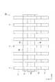
上記実施形態に加えて、図7に示されるように、検査具1Aは、連結部材5Aに切れ目22が設けられていてもよい。切れ目22は、バッキングシート7の長手方向に沿って設けられている。切れ目22は、例えば、隣り合う検査体3の中央に設けられている。この構成では、切れ目22に沿って連結部材5Aを分断することにより、検査体3を一又は複数に分離できる。したがって、使用形態に応じて、検査体3の数を適宜設定できる。 In addition to the embodiment described above, as shown in FIG. 7, in the
上記実施形態では、連結部材5の端部5bがコンジュゲートパッド15の展開方向の終端部に位置している形態を一例に説明した。しかし、連結部材5の端部5bは、必ずしも、コンジュゲートパッド15の展開方向の終端部に位置していなくてもよい。 In the said embodiment, the form which the
上記実施形態では、連結部材5の端部5aがバッキングシート7の端部8aに位置している形態を一例に説明した。しかし、図8に示す検査具1Bのように、連結部材の端部5aが、バッキングシート7の端部8aよりも展開方向下流側に位置していてもよい。 In the said embodiment, the form in which the
上記実施形態では、検査体3がサンプルパッド13及びコンジュゲートパッド15を有する形態を一例に説明した。しかし、サンプルパッド13及びコンジュゲートパッド15が設けられていなくてもよい。例えば、図9に示す検査具1Cでは、検査体3Aは、バッキングシート7と、メンブレン9Aと、吸収パッド11と、を有している。つまり、検査体3Aには、サンプルパッド及びコンジュゲートパッドが設けられていない。また、サンプルパッド13及びコンジュゲートパッド15の少なくとも一方が設けられていなくてもよい。なお、コンジュゲートパッド15を設けない場合には、標的物質を着色粒子等と容器内で予め反応させ、生じた複合体を検査体に展開して検出する。 In the said embodiment, the
上記実施形態に加えて、検査具1は、一部又は全部が透明な保護フィルム等で覆われていてもよい。サンプルパッド13の展開方向の始端部側の一部は露出していることが好ましい。保護フィルムで覆うことにより、例えば、サンプルパッド13以外の部分において検査具1に液体が付着することを抑制できる。 In addition to the above embodiment, the
上記実施形態では、連結部材5とバッキングシート7とが別部材である形態を一例に説明した。しかし、連結部材とバッキングシートとが一体に成形された形態であってもよい。 In the said embodiment, the
1,1A,1B,1C…検査具、3,3A…検査体、5…連結部材、5a,5b…端部、7…バッキングシート(基材)、7a…第1面(一面)、8a,8b…端部、9,9A…メンブレン(検出部)、11…吸収パッド(吸収部)、13…サンプルパッド(採取部)、15…コンジュゲートパッド(試薬保持部)。 DESCRIPTION OF
Claims (9)
Translated fromJapanese前記一方向に直交する他方向において複数の前記検査体が所定の間隔をあけて配置されるように、複数の前記検査体を連結する連結部材と、を備え、
前記連結部材の少なくとも一部は、前記検出部における前記展開方向の始端部側に位置する前記基材の端部と、前記基材の一方向における中央部との間の範囲内に設けられている、検査具。A base material extending in one direction; a detection unit that is arranged on one surface of the base material and that develops a test liquid and detects and displays a target substance contained in the test liquid; and the base material A plurality of test bodies each having an absorbing part that is disposed on one side of the detecting part in the developing direction in the developing direction and absorbs the test liquid;
A connecting member that connects the plurality of inspection bodies so that the plurality of inspection bodies are arranged at a predetermined interval in another direction orthogonal to the one direction,
At least a part of the connecting member is provided in a range between an end portion of the base material located on a start end side in the development direction in the detection portion and a central portion in one direction of the base material. There is an inspection tool.
前記検出部は、前記採取部と前記吸収部との間に配置されている、請求項1に記載の検査具。The inspection body is disposed on the start end side on one surface of the base material, and has a collection unit for collecting the test liquid,
The inspection tool according to claim 1, wherein the detection unit is disposed between the collection unit and the absorption unit.
前記基材の前記一面に直交する方向は、前記一方向及び前記他方向と直交している、請求項5に記載の検査具。The one surface of the base material of each of the plurality of inspection bodies faces the same direction,
The inspection tool according to claim 5, wherein a direction orthogonal to the one surface of the base material is orthogonal to the one direction and the other direction.
Priority Applications (1)
| Application Number | Priority Date | Filing Date | Title |
|---|---|---|---|
| JP2016150026AJP6889990B2 (en) | 2016-07-29 | 2016-07-29 | Inspection tool |
Applications Claiming Priority (1)
| Application Number | Priority Date | Filing Date | Title |
|---|---|---|---|
| JP2016150026AJP6889990B2 (en) | 2016-07-29 | 2016-07-29 | Inspection tool |
Publications (2)
| Publication Number | Publication Date |
|---|---|
| JP2018017681Atrue JP2018017681A (en) | 2018-02-01 |
| JP6889990B2 JP6889990B2 (en) | 2021-06-18 |
Family
ID=61076683
Family Applications (1)
| Application Number | Title | Priority Date | Filing Date |
|---|---|---|---|
| JP2016150026AActiveJP6889990B2 (en) | 2016-07-29 | 2016-07-29 | Inspection tool |
Country Status (1)
| Country | Link |
|---|---|
| JP (1) | JP6889990B2 (en) |
Citations (10)
| Publication number | Priority date | Publication date | Assignee | Title |
|---|---|---|---|---|
| JPS59228943A (en)* | 1983-06-06 | 1984-12-22 | マイルス・ラボラトリ−ズ・インコ−ポレ−テツド | Reagent test tool holder device |
| JPS63502927A (en)* | 1985-11-25 | 1988-10-27 | インスティティ・ナショナ−ル・ド・ラ・サンテ・エ・ド・ラ・ルシェルシュ・メディカ−ル‐インサーム | Novel diagnostic agent |
| JPH09297139A (en)* | 1996-05-02 | 1997-11-18 | Dainabotsuto Kk | Chromatographic immunoanalyzer |
| JPH11506213A (en)* | 1996-03-11 | 1999-06-02 | アメリカン バイオ メディカ コーポレーション | Equipment for collecting, testing and transporting body fluid samples |
| US20020001854A1 (en)* | 1999-07-29 | 2002-01-03 | Lee Jin Po | Multiple analyte assay device with sample integrity monitoring system |
| JP2004037453A (en)* | 2002-04-15 | 2004-02-05 | Becton Dickinson & Co | Use of multi-pin platforms as anchor devices |
| JP2005504320A (en)* | 2001-09-25 | 2005-02-10 | プリオニクス アーゲー | Test strip for detection of prion protein |
| JP2005509852A (en)* | 2001-11-14 | 2005-04-14 | プリオン ディベロプメンタル ラボラトリーズ, インコーポレイテッド | Rapid prion detection assay |
| JP2007523335A (en)* | 2004-02-19 | 2007-08-16 | プリオニクス アーゲー | Apparatus and method for optical evaluation of test piece |
| WO2011032278A1 (en)* | 2009-09-17 | 2011-03-24 | Neoventures Biotechnology Limited | A method and apparatus for lateral flow determination of analyte concentration |
- 2016
- 2016-07-29JPJP2016150026Apatent/JP6889990B2/enactiveActive
Patent Citations (10)
| Publication number | Priority date | Publication date | Assignee | Title |
|---|---|---|---|---|
| JPS59228943A (en)* | 1983-06-06 | 1984-12-22 | マイルス・ラボラトリ−ズ・インコ−ポレ−テツド | Reagent test tool holder device |
| JPS63502927A (en)* | 1985-11-25 | 1988-10-27 | インスティティ・ナショナ−ル・ド・ラ・サンテ・エ・ド・ラ・ルシェルシュ・メディカ−ル‐インサーム | Novel diagnostic agent |
| JPH11506213A (en)* | 1996-03-11 | 1999-06-02 | アメリカン バイオ メディカ コーポレーション | Equipment for collecting, testing and transporting body fluid samples |
| JPH09297139A (en)* | 1996-05-02 | 1997-11-18 | Dainabotsuto Kk | Chromatographic immunoanalyzer |
| US20020001854A1 (en)* | 1999-07-29 | 2002-01-03 | Lee Jin Po | Multiple analyte assay device with sample integrity monitoring system |
| JP2005504320A (en)* | 2001-09-25 | 2005-02-10 | プリオニクス アーゲー | Test strip for detection of prion protein |
| JP2005509852A (en)* | 2001-11-14 | 2005-04-14 | プリオン ディベロプメンタル ラボラトリーズ, インコーポレイテッド | Rapid prion detection assay |
| JP2004037453A (en)* | 2002-04-15 | 2004-02-05 | Becton Dickinson & Co | Use of multi-pin platforms as anchor devices |
| JP2007523335A (en)* | 2004-02-19 | 2007-08-16 | プリオニクス アーゲー | Apparatus and method for optical evaluation of test piece |
| WO2011032278A1 (en)* | 2009-09-17 | 2011-03-24 | Neoventures Biotechnology Limited | A method and apparatus for lateral flow determination of analyte concentration |
Also Published As
| Publication number | Publication date |
|---|---|
| JP6889990B2 (en) | 2021-06-18 |
Similar Documents
| Publication | Publication Date | Title |
|---|---|---|
| US10996221B2 (en) | Multiplexed lateral flow assay systems and methods for their use | |
| US7256053B2 (en) | Diagnostic device for analyte detection | |
| CN101326442B (en) | Metering strip and method for lateral flow assay devices | |
| EP0010456A1 (en) | Liquid transport device | |
| CA2906302C (en) | Diagnostic test device with improved structure | |
| CN102782495A (en) | Methods and devices for enhancing sensitivity and assessing sample sufficiency and reagent reactivity in rapid lateral flow immunoassays | |
| EP2643696B1 (en) | Assay device | |
| JP4993757B2 (en) | Immunochromatography equipment | |
| JP2006091023A (en) | Integrated package holder device for immuno-chromatography assay of flow-through or dipstick type | |
| US9885710B2 (en) | Immunoassay utilizing trapping conjugate | |
| JP4773909B2 (en) | Immunochromatography kit, test container | |
| ES2702296T3 (en) | Exam kit | |
| US20200355679A1 (en) | Immunochromatographic test device | |
| JP4547272B2 (en) | Immunochromatographic test equipment | |
| US20060205086A1 (en) | Diagnostic device | |
| US20210129138A1 (en) | Lateral flow test arrangement suitable for detection of an analyte in saliva | |
| JP2018017681A (en) | Inspection tool | |
| WO2019131606A1 (en) | Inspection device | |
| JP2019109090A (en) | Device for immunochromatographic testing | |
| US11073519B2 (en) | Lateral flow testing | |
| JP5092836B2 (en) | Immunochromatography measuring device | |
| JP4691476B2 (en) | Chromatography kit, test container | |
| EP2835645A1 (en) | Lateral flow membrane and immunoassay device | |
| CN117730256A (en) | Test kit and method for producing test strip for test | |
| ES2696677T3 (en) | Kit, strip of solid support units, support and method to detect at least two analytes |
Legal Events
| Date | Code | Title | Description |
|---|---|---|---|
| A621 | Written request for application examination | Free format text:JAPANESE INTERMEDIATE CODE: A621 Effective date:20190524 | |
| A977 | Report on retrieval | Free format text:JAPANESE INTERMEDIATE CODE: A971007 Effective date:20200226 | |
| A131 | Notification of reasons for refusal | Free format text:JAPANESE INTERMEDIATE CODE: A131 Effective date:20200331 | |
| A521 | Request for written amendment filed | Free format text:JAPANESE INTERMEDIATE CODE: A523 Effective date:20200522 | |
| A131 | Notification of reasons for refusal | Free format text:JAPANESE INTERMEDIATE CODE: A131 Effective date:20201013 | |
| A521 | Request for written amendment filed | Free format text:JAPANESE INTERMEDIATE CODE: A523 Effective date:20201211 | |
| TRDD | Decision of grant or rejection written | ||
| A01 | Written decision to grant a patent or to grant a registration (utility model) | Free format text:JAPANESE INTERMEDIATE CODE: A01 Effective date:20210511 | |
| A61 | First payment of annual fees (during grant procedure) | Free format text:JAPANESE INTERMEDIATE CODE: A61 Effective date:20210524 | |
| R150 | Certificate of patent or registration of utility model | Ref document number:6889990 Country of ref document:JP Free format text:JAPANESE INTERMEDIATE CODE: R150 | |
| R250 | Receipt of annual fees | Free format text:JAPANESE INTERMEDIATE CODE: R250 | |
| R250 | Receipt of annual fees | Free format text:JAPANESE INTERMEDIATE CODE: R250 |