JP2018014786A - Electric motor with power generation and power supply function at coil end part - Google Patents
Electric motor with power generation and power supply function at coil end partDownload PDFInfo
- Publication number
- JP2018014786A JP2018014786AJP2016141414AJP2016141414AJP2018014786AJP 2018014786 AJP2018014786 AJP 2018014786AJP 2016141414 AJP2016141414 AJP 2016141414AJP 2016141414 AJP2016141414 AJP 2016141414AJP 2018014786 AJP2018014786 AJP 2018014786A
- Authority
- JP
- Japan
- Prior art keywords
- electric motor
- electric
- rotor
- winding
- power
- Prior art date
- Legal status (The legal status is an assumption and is not a legal conclusion. Google has not performed a legal analysis and makes no representation as to the accuracy of the status listed.)
- Pending
Links
- 238000010248power generationMethods0.000titleabstractdescription9
- 230000006698inductionEffects0.000claimsabstractdescription25
- 238000004804windingMethods0.000claimsabstractdescription21
- 230000004907fluxEffects0.000claimsabstractdescription7
- 230000005540biological transmissionEffects0.000claimsdescription4
- 239000004519greaseSubstances0.000claimsdescription3
- 239000004020conductorSubstances0.000abstractdescription2
- 238000010586diagramMethods0.000description6
- 230000001133accelerationEffects0.000description4
- 238000001514detection methodMethods0.000description3
- WABPQHHGFIMREM-UHFFFAOYSA-Nlead(0)Chemical compound[Pb]WABPQHHGFIMREM-UHFFFAOYSA-N0.000description2
- 238000001816coolingMethods0.000description1
- 230000000694effectsEffects0.000description1
- 230000005674electromagnetic inductionEffects0.000description1
- 238000009434installationMethods0.000description1
- 238000012423maintenanceMethods0.000description1
- 238000005259measurementMethods0.000description1
Images

Classifications
- H—ELECTRICITY
- H02—GENERATION; CONVERSION OR DISTRIBUTION OF ELECTRIC POWER
- H02K—DYNAMO-ELECTRIC MACHINES
- H02K11/00—Structural association of dynamo-electric machines with electric components or with devices for shielding, monitoring or protection
- H02K11/0094—Structural association with other electrical or electronic devices
- H—ELECTRICITY
- H02—GENERATION; CONVERSION OR DISTRIBUTION OF ELECTRIC POWER
- H02K—DYNAMO-ELECTRIC MACHINES
- H02K11/00—Structural association of dynamo-electric machines with electric components or with devices for shielding, monitoring or protection
- H02K11/20—Structural association of dynamo-electric machines with electric components or with devices for shielding, monitoring or protection for measuring, monitoring, testing, protecting or switching
- H02K11/25—Devices for sensing temperature, or actuated thereby
- H—ELECTRICITY
- H02—GENERATION; CONVERSION OR DISTRIBUTION OF ELECTRIC POWER
- H02K—DYNAMO-ELECTRIC MACHINES
- H02K11/00—Structural association of dynamo-electric machines with electric components or with devices for shielding, monitoring or protection
- H02K11/20—Structural association of dynamo-electric machines with electric components or with devices for shielding, monitoring or protection for measuring, monitoring, testing, protecting or switching
- H02K11/27—Devices for sensing current, or actuated thereby
- H—ELECTRICITY
- H02—GENERATION; CONVERSION OR DISTRIBUTION OF ELECTRIC POWER
- H02K—DYNAMO-ELECTRIC MACHINES
- H02K11/00—Structural association of dynamo-electric machines with electric components or with devices for shielding, monitoring or protection
- H02K11/30—Structural association with control circuits or drive circuits
- H02K11/33—Drive circuits, e.g. power electronics
- H—ELECTRICITY
- H02—GENERATION; CONVERSION OR DISTRIBUTION OF ELECTRIC POWER
- H02K—DYNAMO-ELECTRIC MACHINES
- H02K11/00—Structural association of dynamo-electric machines with electric components or with devices for shielding, monitoring or protection
- H02K11/30—Structural association with control circuits or drive circuits
- H02K11/35—Devices for recording or transmitting machine parameters, e.g. memory chips or radio transmitters for diagnosis
- H—ELECTRICITY
- H02—GENERATION; CONVERSION OR DISTRIBUTION OF ELECTRIC POWER
- H02K—DYNAMO-ELECTRIC MACHINES
- H02K5/00—Casings; Enclosures; Supports
- H02K5/04—Casings or enclosures characterised by the shape, form or construction thereof
- H02K5/16—Means for supporting bearings, e.g. insulating supports or means for fitting bearings in the bearing-shields
Landscapes
- Engineering & Computer Science (AREA)
- Power Engineering (AREA)
- Microelectronics & Electronic Packaging (AREA)
Abstract
Description
Translated fromJapanese本発明は、電動機に関し、特に、電動機のコイルエンド近傍に誘導発電コイルを設け、その発電電力を内部のセンサ、電気回路基板、またはアクチュエータに給電する機能を有する電動機に関する。 The present invention relates to an electric motor, and more particularly, to an electric motor having a function of providing an induction generating coil near the coil end of the electric motor and supplying the generated power to an internal sensor, electric circuit board, or actuator.
電動機の知能化と多機能化に伴い、電動機の内部にセンサやアクチュエータを設置する要求がある。また、そのセンサやアクチュエータの数や種類も増えている。一方、センサやアクチュエータを駆動するためには、電力が必要である。電動機の内部にセンサやアクチュエータを設けた場合、これらのセンサやアクチュエータに給電するためには、外部から給電するための導線または内部電池が必要であった。 As motors become more intelligent and multifunctional, there is a need to install sensors and actuators inside the motor. In addition, the number and types of sensors and actuators are increasing. On the other hand, electric power is required to drive the sensors and actuators. When sensors and actuators are provided inside the electric motor, in order to supply power to these sensors and actuators, a lead wire or an internal battery for supplying power from the outside is necessary.
送電コイルの電磁誘導によって発電コイルで発電する例が知られている(例えば、特許文献1)。従来の電動機においては、稼働時に巻線のコイルエンド部分で発生する変化磁場を利用してこなかった。 An example of generating power with a power generation coil by electromagnetic induction of a power transmission coil is known (for example, Patent Document 1). The conventional electric motor has not used the changing magnetic field generated at the coil end portion of the winding during operation.
外部導線から電力を供給する場合は、給電する給電線が多く、複雑であるという問題があった。また、センサを内部電池で駆動する場合は、電池交換や保守など、工数がかかるという問題もあった。 When power is supplied from an external conductor, there is a problem that there are many power feed lines to be fed and are complicated. In addition, when the sensor is driven by an internal battery, there is a problem that man-hours such as battery replacement and maintenance are required.
その他、センサやアクチュエータの数と設置場所が制限されている、外部から電動機の内部に導線を通すと、電動機の防水性が低下するなどの問題もある。 In addition, the number of sensors and actuators and the installation location are limited, and there is a problem that the waterproofness of the electric motor is lowered when a conducting wire is passed from the outside into the electric motor.
本発明の一実施例に係る電動機は、巻回された巻線を含むステータ、及び該ステータの内側に配置されるロータを備えた電動機であって、電気回路部と、巻線のコイルエンド近傍に設置され、巻線が発生する磁束変化によって発電する誘導発電コイルと、を有し、電気回路部は、誘導発電コイルが発電し、給電する電力によって駆動されることを特徴とする。 An electric motor according to an embodiment of the present invention is an electric motor including a stator including a wound winding and a rotor disposed inside the stator, and an electric circuit portion and the vicinity of a coil end of the winding And an induction generator coil that generates electric power by changing a magnetic flux generated by the winding, and the electric circuit unit is driven by the electric power generated and supplied by the induction generator coil.
本発明の一実施例に係る電動機によれば、コイルエンドで発生する磁界によって発電した電力を電動機の内部のセンサやアクチュエータに給電することができるため、電動機の外部からセンサやアクチュエータへの導線を省略することが可能となるという効果が得られる。 According to the electric motor according to one embodiment of the present invention, the electric power generated by the magnetic field generated at the coil end can be supplied to the sensor or actuator inside the electric motor. The effect that it can be omitted is obtained.
以下、図面を参照して、本発明に係る電動機について説明する。 Hereinafter, an electric motor according to the present invention will be described with reference to the drawings.
[実施例1]
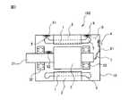
まず、本発明の実施例1に係る電動機について説明する。図1は、本発明の実施例1に係る電動機の構成図である。本発明の実施例1に係る電動機101は、巻回された巻線1を含むステータ2、及び該ステータ2の内側に配置されるロータ3を備えた電動機であって、電気回路部4と、誘導発電コイル6と、を有している。巻線1、ステータ2、ロータ3、軸受32、電気回路部4及び誘導発電コイル6は、電動機101の筐体10の内部に設けられている。なお、図1は電動機101の断面図を示しており、ステータ2は筒状の構造を備えている。ロータ3が回転することにより、軸受32で支持されたシャフト31が回転する。[Example 1]
First, the electric motor according to
誘導発電コイル6は、巻線のコイルエンド5の近傍に設置され、巻線1が発生する磁束変化によって発電する。ここで、「コイルエンド5の近傍」とは、コイルエンドによって生じる磁界の変化が観測される範囲をいう。 The induction
誘導発電コイル6を巻線1のコイルエンド5の一方の端部に設けた場合、コイルエンドの他方の端部に第2誘導発電コイル61を設けるようにしてもよい。さらに、ロータ3のシャフト31の近傍に第3誘導発電コイル62を設けるようにしてもよい。このように、誘導発電コイルは1つまたは複数設けることができる。 When the
電気回路部4は、誘導発電コイル6が発電し、給電する電力によって駆動される。電気回路部4は、給電線8により誘導発電コイル6と電気的に接続されている。電気回路部4は充電機能を備えることが好ましい。 The electric circuit unit 4 is driven by electric power generated by the induction
電気回路部4は、巻線1の電流を検出する電流センサであってもよい。 The electric circuit unit 4 may be a current sensor that detects the current of the
電気回路部4は、ステータ2の温度または振動を検出する温度センサまたは振動センサであってもよい。ステータ2用の温度センサとして熱電対等を用いることができる。また、ステータ2用の振動センサとして、振動の加速度成分のピーク値を検出する圧電式加速度型振動センサ等を用いることができる。 The electric circuit unit 4 may be a temperature sensor or a vibration sensor that detects the temperature or vibration of the
電気回路部4は、ロータ3の温度または振動を検出する温度センサまたは振動センサであってもよい。ロータ3用の温度センサとして熱電対等を用いることができる。また、ロータ3用の振動センサとして、振動の加速度成分のピーク値を検出する圧電式加速度型振動センサ等を用いることができる。 The electric circuit unit 4 may be a temperature sensor or a vibration sensor that detects the temperature or vibration of the
電気回路部4は、電動機101の内部の湿度を検出する湿度センサであってもよい。 The electric circuit unit 4 may be a humidity sensor that detects the humidity inside the
電気回路部4は、ロータ3を支える軸受32の温度または振動を検出する温度センサまたは振動センサであってもよい。 The electric circuit unit 4 may be a temperature sensor or a vibration sensor that detects the temperature or vibration of the
電気回路部4は、電動機101の内部の磁束強度を検出する磁気センサであってもよい。磁気センサとして、磁界強度や磁界方向に応じて電圧や電気抵抗が変化するホール素子や磁気抵抗素子等を用いることができる。 The electric circuit unit 4 may be a magnetic sensor that detects the magnetic flux intensity inside the
従って、電気回路部4は、上記のように、巻線1の電流、ステータ2の温度または振動、ロータ3の温度または振動、電動機101の内部の湿度、ロータ3を支える軸受32の温度または振動、電動機101の内部の磁束強度のうち、少なくとも1つを測定するセンサであることが好ましい。 Accordingly, as described above, the electric circuit unit 4 is configured to have the current of the
以上説明したように、本発明の実施例1に係る電動機によれば、誘導発電コイルによる発電電力を電動機の内部に設けたセンサに給電することができるため、電動機の外部からセンサに給電するための導線を省略することができる。 As described above, according to the electric motor according to the first embodiment of the present invention, the electric power generated by the induction power generation coil can be supplied to the sensor provided in the electric motor, and thus the electric power is supplied to the sensor from the outside of the electric motor. The conducting wire can be omitted.
さらに、本発明の実施例1に係る電動機によれば、内部給電によって、センサを従来設置し難い場所にも設置することができる。例えば、電動機のロータの近傍に誘導発電コイルを設置すれば、電動機のロータの近傍に温度センサまたは振動センサを設置することができる。また、外部からの導線や信号線をなくすことができるため、電動機の防水性を向上させることができる。 Furthermore, according to the electric motor which concerns on Example 1 of this invention, a sensor can be installed in the place where it is difficult to install conventionally by internal electric power feeding. For example, if an induction generator coil is installed in the vicinity of the rotor of the electric motor, a temperature sensor or a vibration sensor can be installed in the vicinity of the rotor of the electric motor. Moreover, since the lead wire and signal line from the outside can be eliminated, the waterproofness of the electric motor can be improved.
[実施例2]
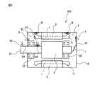
次に、本発明の実施例2に係る電動機について説明する。図2は、本発明の実施例2に係る電動機の構成図である。本発明の実施例2に係る電動機102が、実施例1に係る電動機101と異なっている点は、電気回路部4が、電動機102の内部の異物または冷却ファン(図示せず)の異物を除去するアクチュエータ7、ロータ3を支える軸受32のグリスを充填するアクチュエータ、及びロータ3にブレーキトルクを掛ける機構のうち、少なくとも1つを駆動する点である。本発明の実施例2に係る電動機のその他の構成は、実施例1に係る電動機の対応する構成と同様であるので詳細な説明は省略する。[Example 2]
Next, an electric motor according to
アクチュエータ7は電気回路部4から第2給電線81によって給電され、動作する。ロータ3を支える軸受32のグリスを充填するアクチュエータ(図示せず)、及びロータ3にブレーキトルクを掛ける機構(図示せず)も、電気回路部4から給電線(図示せず)によって給電され、動作する。 The
以上説明したように、本発明の実施例2に係る電動機によれば、誘導発電コイルによる発電電力を電動機の内部に設けたアクチュエータやブレーキ機構に給電することができるため、電動機の外部からアクチュエータやブレーキ機構に給電するための導線を省略することができる。 As described above, according to the electric motor according to the second embodiment of the present invention, the electric power generated by the induction generator coil can be supplied to the actuator and the brake mechanism provided inside the electric motor. The conducting wire for supplying power to the brake mechanism can be omitted.
[実施例3]
次に、本発明の実施例3に係る電動機について説明する。図3は、本発明の実施例3に係る電動機の構成図である。本発明の実施例3に係る電動機103が、実施例1に係る電動機101と異なっている点は、電気回路部4が、無線送受信機能を備えている点である。本発明の実施例3に係る電動機のその他の構成は、実施例1に係る電動機の対応する構成と同様であるので詳細な説明は省略する。[Example 3]
Next, an electric motor according to
電気回路部4が無線送受信機能を備える場合の例として、無線センサが挙げられる。例えば、電気回路部4の無線受信センサが外部から測定指令を受ける場合は、無線センサ9を軸受32の温度又は振動を検出するセンサとして用いることができる。無線センサ9は、第3給電線82を介して第2誘導発電コイル61から給電されることによって動作することができる。無線センサ9が検出した軸受32の温度又は振動に関する検出データは、無線により外部に送信することができる。 An example of the case where the electric circuit unit 4 has a wireless transmission / reception function is a wireless sensor. For example, when the wireless reception sensor of the electric circuit unit 4 receives a measurement command from the outside, the wireless sensor 9 can be used as a sensor for detecting the temperature or vibration of the
また、第2無線センサ91をコイルエンド5の近傍に設けて巻線1の温度又は振動を検出するようにしてもよい。第2無線センサ91は、第4給電線83を介して第2誘導発電コイル61から給電されることによって動作することができる。第2無線センサ91が検出した巻線1の温度又は振動に関する検出データは、無線により外部に送信することができる。 Alternatively, the
さらに、第3無線センサ92をロータ3のシャフト31の近傍に設けてロータ3の温度又は振動を検出するようにしてもよい。第3無線センサ92は、第5給電線84を介して第3誘導発電コイル62から給電されることによって動作することができる。第3無線センサ92が検出したロータ3の温度又は振動に関する検出データは、無線により外部に送信することができる。また、過大な温度や振動を検出すれば、リアルタイムで外部へ送信や通知することができる。 Further, a
以上説明したように、本発明の実施例3に係る電動機によれば、無線センサを用いることにより、センサの信号線も省略できる。さらに、本発明の実施例3に係る電動機によれば、電動機の知能化、多機能化と信頼性向上に貢献することができる。 As described above, according to the electric motor according to the third embodiment of the present invention, the signal line of the sensor can be omitted by using the wireless sensor. Furthermore, according to the electric motor according to the third embodiment of the present invention, it is possible to contribute to making the motor intelligent, multifunctional, and improving reliability.
1 巻線
2 ステータ
3 ロータ
31 シャフト
32 軸受
4 電気回路部
5 コイルエンド
6 誘導発電コイル
61 第2誘導発電コイル
62 第3誘導発電コイル
7 アクチュエータ
8 給電線
81 第2給電線
82 第3給電線
83 第4給電線
84 第5給電線
9 無線センサ
91 第2無線センサ
92 第3無線センサ
10 筐体DESCRIPTION OF
Claims (4)
Translated fromJapanese電気回路部と、
前記巻線のコイルエンドの近傍に設置され、前記巻線が発生する磁束変化によって発電する誘導発電コイルと、を有し、
前記電気回路部は、前記誘導発電コイルが発電し、給電する電力によって駆動される、
ことを特徴とする電動機。An electric motor including a stator including wound windings, and a rotor disposed inside the stator,
An electric circuit section;
An induction generator coil that is installed in the vicinity of the coil end of the winding and generates power by a magnetic flux change generated by the winding;
The electric circuit unit is driven by electric power generated and fed by the induction generator coil.
An electric motor characterized by that.
Priority Applications (4)
| Application Number | Priority Date | Filing Date | Title |
|---|---|---|---|
| JP2016141414AJP2018014786A (en) | 2016-07-19 | 2016-07-19 | Electric motor with power generation and power supply function at coil end part |
| CN201710384949.XACN107634629A (en) | 2016-07-19 | 2017-05-26 | Motor |
| US15/623,379US20180026496A1 (en) | 2016-07-19 | 2017-06-15 | Motor having function of generating and feeding electric power at coil end portion |
| DE102017115625.9ADE102017115625A1 (en) | 2016-07-19 | 2017-07-12 | A motor having a function for generating and supplying electrical energy at a coil end portion |
Applications Claiming Priority (1)
| Application Number | Priority Date | Filing Date | Title |
|---|---|---|---|
| JP2016141414AJP2018014786A (en) | 2016-07-19 | 2016-07-19 | Electric motor with power generation and power supply function at coil end part |
Publications (1)
| Publication Number | Publication Date |
|---|---|
| JP2018014786Atrue JP2018014786A (en) | 2018-01-25 |
Family
ID=60890434
Family Applications (1)
| Application Number | Title | Priority Date | Filing Date |
|---|---|---|---|
| JP2016141414APendingJP2018014786A (en) | 2016-07-19 | 2016-07-19 | Electric motor with power generation and power supply function at coil end part |
Country Status (4)
| Country | Link |
|---|---|
| US (1) | US20180026496A1 (en) |
| JP (1) | JP2018014786A (en) |
| CN (1) | CN107634629A (en) |
| DE (1) | DE102017115625A1 (en) |
Families Citing this family (9)
| Publication number | Priority date | Publication date | Assignee | Title |
|---|---|---|---|---|
| KR102127750B1 (en)* | 2015-08-04 | 2020-06-29 | 엘지이노텍 주식회사 | Circuit board, motor and electronic power steering system |
| ES2773200T3 (en)* | 2016-06-21 | 2020-07-09 | Bombardier Transp Gmbh | An electric machine |
| JP2018091247A (en)* | 2016-12-05 | 2018-06-14 | 日本電産コパル電子株式会社 | Blower |
| JP6755786B2 (en)* | 2016-12-05 | 2020-09-16 | 日本電産コパル電子株式会社 | Blower and a blower system with the blower |
| US10135310B2 (en)* | 2017-01-11 | 2018-11-20 | Infinitum Electric Inc. | System and apparatus for modular axial field rotary energy device |
| US20190234227A1 (en)* | 2018-01-29 | 2019-08-01 | Siemens Energy, Inc. | Powering generator instrumentation via magnetic induction |
| DE102021201610A1 (en)* | 2021-02-19 | 2022-08-25 | Zf Friedrichshafen Ag | Rotor for an electric machine and electric machine with a rotor |
| DE102021201605A1 (en)* | 2021-02-19 | 2022-08-25 | Zf Friedrichshafen Ag | Rotor for an electric machine and electric machine with a rotor |
| US11866187B1 (en)* | 2022-10-14 | 2024-01-09 | Beta Air, Llc | Electric propulsion system with power harvesting system |
Citations (5)
| Publication number | Priority date | Publication date | Assignee | Title |
|---|---|---|---|---|
| JPS5587145U (en)* | 1978-12-08 | 1980-06-16 | ||
| JP2011250487A (en)* | 2010-05-21 | 2011-12-08 | Toshiba Corp | Dust collector |
| JP2013526826A (en)* | 2010-05-19 | 2013-06-24 | シーレイト リミテッド ライアビリティー カンパニー | Heat removal from motor |
| JP2014190531A (en)* | 2013-03-28 | 2014-10-06 | Mitsubishi Electric Corp | Braking device and method of manufacturing the same |
| JP2015213383A (en)* | 2014-05-01 | 2015-11-26 | 東芝三菱電機産業システム株式会社 | Rotary electric machine |
Family Cites Families (1)
| Publication number | Priority date | Publication date | Assignee | Title |
|---|---|---|---|---|
| JP6416567B2 (en) | 2014-09-19 | 2018-10-31 | 株式会社Soken | Wireless power feeder |
- 2016
- 2016-07-19JPJP2016141414Apatent/JP2018014786A/enactivePending
- 2017
- 2017-05-26CNCN201710384949.XApatent/CN107634629A/enactivePending
- 2017-06-15USUS15/623,379patent/US20180026496A1/ennot_activeAbandoned
- 2017-07-12DEDE102017115625.9Apatent/DE102017115625A1/ennot_activeWithdrawn
Patent Citations (5)
| Publication number | Priority date | Publication date | Assignee | Title |
|---|---|---|---|---|
| JPS5587145U (en)* | 1978-12-08 | 1980-06-16 | ||
| JP2013526826A (en)* | 2010-05-19 | 2013-06-24 | シーレイト リミテッド ライアビリティー カンパニー | Heat removal from motor |
| JP2011250487A (en)* | 2010-05-21 | 2011-12-08 | Toshiba Corp | Dust collector |
| JP2014190531A (en)* | 2013-03-28 | 2014-10-06 | Mitsubishi Electric Corp | Braking device and method of manufacturing the same |
| JP2015213383A (en)* | 2014-05-01 | 2015-11-26 | 東芝三菱電機産業システム株式会社 | Rotary electric machine |
Also Published As
| Publication number | Publication date |
|---|---|
| DE102017115625A1 (en) | 2018-01-25 |
| CN107634629A (en) | 2018-01-26 |
| US20180026496A1 (en) | 2018-01-25 |
Similar Documents
| Publication | Publication Date | Title |
|---|---|---|
| JP2018014786A (en) | Electric motor with power generation and power supply function at coil end part | |
| KR102146023B1 (en) | Motor and electronic power steering system having the same | |
| JP4628460B2 (en) | Rotating electric machine and manufacturing method thereof | |
| US9985503B2 (en) | Motor unit having a detector interposed between a motor and an arithmetic board | |
| EP3109979B1 (en) | Motor drive device | |
| JP2010104212A (en) | Brushless motor | |
| US6734589B2 (en) | Electric motor | |
| JP2007221976A (en) | Brushless motor | |
| EP3416282A1 (en) | Motor device | |
| US11456642B2 (en) | Motor device including connection lines and rotation detection unit configuration | |
| US20120181967A1 (en) | Permanent magnet electric machine having an integrated magnetic flux sensor | |
| KR101600992B1 (en) | BLDC motor including dual-rotor, dual-stator and dual-sensor structure, and electric linear actuators including BLDC motor | |
| JP6771848B2 (en) | Electric drive | |
| CN102594031A (en) | Electric machine having an integrated vibration sensor | |
| KR20210028569A (en) | Magnet temperature information output device and rotating electric machine | |
| JP2015089298A (en) | Inverter integrated motor | |
| JP2005160296A (en) | Electric motor with sensor for detecting rotor position | |
| KR20160010820A (en) | Direct current motor without contacting power supplier | |
| JP5832576B2 (en) | Inverter-integrated rotating electrical machine | |
| JP6306479B2 (en) | Motor unit | |
| KR20180072324A (en) | Detecting device for sensing the rotor position and motor having the same | |
| KR200473956Y1 (en) | Apparatus for Detecting DC Motor Rotation | |
| KR20200098456A (en) | Motor and electronic power steering system having the same | |
| JP2009033937A (en) | Permanent magnet motor | |
| JP2009011125A (en) | Motor and bus bar |
Legal Events
| Date | Code | Title | Description |
|---|---|---|---|
| A977 | Report on retrieval | Free format text:JAPANESE INTERMEDIATE CODE: A971007 Effective date:20180613 | |
| A131 | Notification of reasons for refusal | Free format text:JAPANESE INTERMEDIATE CODE: A131 Effective date:20180626 | |
| A521 | Request for written amendment filed | Free format text:JAPANESE INTERMEDIATE CODE: A523 Effective date:20180802 | |
| A02 | Decision of refusal | Free format text:JAPANESE INTERMEDIATE CODE: A02 Effective date:20190108 |