Movatterモバイル変換


[0]ホーム

URL:


JP2018014111A - Electronic apparatus - Google Patents

Electronic apparatus
Download PDF

Info

Publication number
JP2018014111A
JP2018014111AJP2017150571AJP2017150571AJP2018014111AJP 2018014111 AJP2018014111 AJP 2018014111AJP 2017150571 AJP2017150571 AJP 2017150571AJP 2017150571 AJP2017150571 AJP 2017150571AJP 2018014111 AJP2018014111 AJP 2018014111A
Authority
JP
Japan
Prior art keywords
mode
electronic device
fingerprint
control unit
user authentication
Prior art date
Legal status (The legal status is an assumption and is not a legal conclusion. Google has not performed a legal analysis and makes no representation as to the accuracy of the status listed.)
Pending
Application number
JP2017150571A
Other languages
Japanese (ja)
Inventor
聡促 熊野
Toshiyuki Kumano
聡促 熊野
Current Assignee (The listed assignees may be inaccurate. Google has not performed a legal analysis and makes no representation or warranty as to the accuracy of the list.)
Kyocera Corp
Original Assignee
Kyocera Corp
Priority date (The priority date is an assumption and is not a legal conclusion. Google has not performed a legal analysis and makes no representation as to the accuracy of the date listed.)
Filing date
Publication date
Application filed by Kyocera CorpfiledCriticalKyocera Corp
Priority to JP2017150571ApriorityCriticalpatent/JP2018014111A/en
Publication of JP2018014111ApublicationCriticalpatent/JP2018014111A/en
Pendinglegal-statusCriticalCurrent

Links

Images

Classifications

Landscapes

Abstract

PROBLEM TO BE SOLVED: To provide a technique capable of reducing power consumption in an electronic apparatus.SOLUTION: An electronic apparatus includes a display section, a finger print sensor, and a setting section. The display section has a first display mode of not displaying information and a second display mode of displaying information as display modes. The finger print sensor has a detection area to be touched by a finger of a user and has a first detection mode of not detecting a finger print of a finger touching the detection area and a second detection mode of detecting the finger print. The setting section sets the detection mode of the finger print sensor to the second detection mode when the display mode of the display section is the first display mode and also when a predetermined condition is not satisfied, and sets the detection mode to the first detection mode when the display mode is the first display mode and also when a predetermined condition is satisfied.SELECTED DRAWING: Figure 4

Description

Translated fromJapanese

本発明は、電子機器に関する。  The present invention relates to an electronic device.

特許文献1に記載されているように、従来から電子機器に関して様々な技術が開示されている。  As described inPatent Document 1, various techniques have been disclosed for electronic devices.

特開2013−232197号公報JP 2013-232197 A特開2005−159656号公報JP 2005-159656 A

電子機器においては、その消費電力が低いことが望まれる。  In an electronic device, it is desired that the power consumption is low.

そこで、本発明は上述の点に鑑みて成されたものであり、電子機器の消費電力を低減することが可能な技術を提供することを目的とする。  Therefore, the present invention has been made in view of the above points, and an object thereof is to provide a technique capable of reducing the power consumption of an electronic device.

電子機器が開示される。一の実施の形態では、電子機器は、表示部と、指紋センサを含む操作ボタンと、制御部とを備える。制御部は、スリープモードにおいて、指紋センサの検出モードを、指の指紋を検出しない第1検出モードに設定する。制御部は、操作ボタンが押されると、スリープモードを解除して表示部にロック画面を表示するとともに指紋センサの検出モードを第1検出モードから、指の指紋を検出する第2検出モードに変更する。制御部は、操作ボタンが押された後の表示部でのロック画面の表示中において、指紋検出待ち状態となる。制御部は、指紋検出待ち状態において、操作ボタンが押されなくても指紋センサが触れられると、当該指紋センサで検出される指紋に基づいてユーザ認証を実行する。制御部は、ユーザ認証が成功すると、ロック画面以外の画面を表示部に表示する。  An electronic device is disclosed. In one embodiment, an electronic device includes a display unit, an operation button including a fingerprint sensor, and a control unit. In the sleep mode, the control unit sets the detection mode of the fingerprint sensor to the first detection mode in which the fingerprint of the finger is not detected. When the operation button is pressed, the control unit cancels the sleep mode and displays the lock screen on the display unit, and changes the detection mode of the fingerprint sensor from the first detection mode to the second detection mode for detecting the fingerprint of the finger. To do. The control unit enters a fingerprint detection waiting state while the lock screen is displayed on the display unit after the operation button is pressed. When the fingerprint sensor is touched even when the operation button is not pressed in the fingerprint detection waiting state, the control unit executes user authentication based on the fingerprint detected by the fingerprint sensor. When the user authentication is successful, the control unit displays a screen other than the lock screen on the display unit.

電子機器の消費電力を低減することができる。  The power consumption of the electronic device can be reduced.

電子機器の外観の一例を概略的に示す斜視図である。It is a perspective view which shows an example of the external appearance of an electronic device roughly.電子機器の外観の一例を概略的に示す背面図である。It is a rear view which shows roughly an example of the external appearance of an electronic device.指紋検出領域を示す図である。It is a figure which shows a fingerprint detection area.電子機器の電気的構成の一例を示す図である。It is a figure which shows an example of the electrical constitution of an electronic device.表示画面の表示の一例を示す図である。It is a figure which shows an example of the display of a display screen.表示画面の表示の一例を示す図である。It is a figure which shows an example of the display of a display screen.電子機器の動作の一例を示すフローチャートである。It is a flowchart which shows an example of operation | movement of an electronic device.電子機器の動作の一例を示すフローチャートである。It is a flowchart which shows an example of operation | movement of an electronic device.表示画面の表示の一例を示す図である。It is a figure which shows an example of the display of a display screen.電子機器の動作の一例を示すフローチャートである。It is a flowchart which shows an example of operation | movement of an electronic device.電子機器の動作の一例を示すフローチャートである。It is a flowchart which shows an example of operation | movement of an electronic device.電子機器の動作の一例を示すフローチャートである。It is a flowchart which shows an example of operation | movement of an electronic device.

<電子機器の外観>
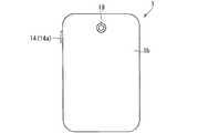
図1は、電子機器1の外観の一例を概略的に示す斜視図である。図2は、電子機器1の外観の一例を概略的に示す背面図である。電子機器1は、例えば、スマートフォン等の携帯電話機である。電子機器1は、基地局及びサーバ等を通じて他の通信装置と通信することが可能である。
<Appearance of electronic equipment>
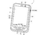
FIG. 1 is a perspective view schematically showing an example of the appearance of theelectronic apparatus 1. FIG. 2 is a rear view schematically showing an example of the appearance of theelectronic apparatus 1. Theelectronic device 1 is a mobile phone such as a smartphone, for example. Theelectronic device 1 can communicate with other communication devices through a base station, a server, and the like.

図1及び図2に示されるように、電子機器1は、当該電子機器1の前面1aに位置するカバーパネル2と、当該カバーパネル2が取り付けられる機器ケース3とを備えている。カバーパネル2及び機器ケース3は、電子機器1の外装を成している。電子機器1の形状は、例えば、平面視において略長方形の板状となっている。  As shown in FIGS. 1 and 2, theelectronic device 1 includes acover panel 2 positioned on thefront surface 1 a of theelectronic device 1 and adevice case 3 to which thecover panel 2 is attached. Thecover panel 2 and thedevice case 3 form the exterior of theelectronic device 1. The shape of theelectronic device 1 is, for example, a substantially rectangular plate shape in plan view.

カバーパネル2には、後述する表示パネル121が表示する、文字、記号、図形等の各種情報が表示される表示領域(表示画面とも呼ばれる)2aが設けられている。カバーパネル2における、表示領域2aを取り囲む周縁部2bの大部分は、例えばフィルム等が貼られることによって黒色となっている。これにより、カバーパネル2の周縁部2bの大部分は、表示パネル121が表示する各種情報が表示されない非表示領域となっている。  Thecover panel 2 is provided with a display area (also referred to as a display screen) 2a on which various information such as characters, symbols, and graphics displayed on thedisplay panel 121 described later is displayed. Most of theperipheral edge portion 2b surrounding thedisplay area 2a in thecover panel 2 is black, for example, by applying a film or the like. Thereby, most of theperipheral edge portion 2b of thecover panel 2 is a non-display area where various information displayed on thedisplay panel 121 is not displayed.

表示領域2aの裏側には、後述するタッチセンサ130が取り付けられている。これにより、ユーザは、表示領域2aを指等の操作子で操作することによって、電子機器1に対して各種指示を与えることができる。  Atouch sensor 130 described later is attached to the back side of thedisplay area 2a. Accordingly, the user can give various instructions to theelectronic device 1 by operating thedisplay area 2a with an operator such as a finger.

図1に示されるように、カバーパネル2の上側端部には、レシーバ穴16が設けられている。さらに、カバーパネル2の上側端部には、後述する前面側撮像部180が有するレンズが電子機器1の外部から視認できるための前面レンズ用透明部18が設けられている。また、カバーパネル2の下側端部にはスピーカ穴17が設けられている。そして、電子機器1の底面1c、つまり機器ケース3の底面(下側の側面)には、マイク穴15が設けられている。  As shown in FIG. 1, areceiver hole 16 is provided at the upper end of thecover panel 2. Furthermore, a front lenstransparent portion 18 is provided at the upper end of thecover panel 2 so that a lens included in the frontside imaging unit 180 described later can be visually recognized from the outside of theelectronic apparatus 1. Aspeaker hole 17 is provided at the lower end of thecover panel 2. Amicrophone hole 15 is provided on the bottom surface 1 c of theelectronic device 1, that is, on the bottom surface (lower side surface) of thedevice case 3.

図2に示されるように、電子機器1の背面1b、つまり機器ケース3の背面の上側端部には、後述する背面側撮像部190が有する撮像レンズが、電子機器1の外部から視認できるための背面レンズ用透明部19が設けられている。  As shown in FIG. 2, an imaging lens of a backside imaging unit 190 described later can be visually recognized from the outside of theelectronic device 1 on the back surface 1 b of theelectronic device 1, that is, the upper end portion of the back surface of thedevice case 3. The rear lenstransparent portion 19 is provided.

機器ケース3の内部には、複数の操作ボタン14が設けられている。各操作ボタン14は、ハードウェアボタンである。具体的には、各操作ボタン14は押しボタンである。操作ボタンは、「操作キー」あるいは「キー」と呼ばれることがある。操作ボタン14は、ユーザが当該操作ボタン14を操作するときに触れる操作領域を有している。操作ボタン14の操作領域は電子機器1の表面から露出している。ユーザは操作ボタン14の操作領域を押すことによって、操作ボタン14を押すことができる。  A plurality ofoperation buttons 14 are provided inside thedevice case 3. Eachoperation button 14 is a hardware button. Specifically, eachoperation button 14 is a push button. The operation buttons are sometimes called “operation keys” or “keys”. Theoperation button 14 has an operation area that is touched when the user operates theoperation button 14. The operation area of theoperation button 14 is exposed from the surface of theelectronic device 1. The user can press theoperation button 14 by pressing the operation area of theoperation button 14.

各操作ボタン14には機能が割り当てられる。電子機器1は、操作ボタン14が押されてオン状態になると、オン状態になった操作ボタン14に割り当てられている機能を実行する。複数の操作ボタン14には、操作ボタン14a〜14dが含まれている。以後、複数の操作ボタン14をまとめて「操作ボタン群140」と呼ぶことがある。また、操作ボタン14が操作されると言えば、操作ボタン14が押されてオン状態になることを意味する。  A function is assigned to eachoperation button 14. When theoperation button 14 is pressed and turned on, theelectronic device 1 executes a function assigned to theoperation button 14 that is turned on. The plurality ofoperation buttons 14 includeoperation buttons 14a to 14d. Hereinafter, the plurality ofoperation buttons 14 may be collectively referred to as “operation button group 140”. If theoperation button 14 is operated, it means that theoperation button 14 is pressed and turned on.

操作ボタン14aは、例えば電源ボタンである。電源ボタンは、電子機器1において、一部の機能を停止したり、停止している状態を復帰(起動)したりするための操作ボタンである。図1及び図2に示されるように、操作ボタン14aは、電子機器1の右側側面1d、つまり機器ケース3の右側側面に設けられている。ユーザは、操作ボタン14aを操作することによって、電子機器1における、一部の機能を停止させたり、停止している機能を復帰させたりすることができる。以後、操作ボタン14aを「電源ボタン14a」と呼ぶことがある。  Theoperation button 14a is, for example, a power button. The power button is an operation button for stopping a part of the functions or returning (starting) the stopped state in theelectronic device 1. As shown in FIGS. 1 and 2, theoperation button 14 a is provided on theright side surface 1 d of theelectronic device 1, that is, on the right side surface of thedevice case 3. By operating theoperation button 14a, the user can stop a part of the functions in theelectronic device 1 or restore the stopped functions. Hereinafter, theoperation button 14a may be referred to as a “power button 14a”.

電源ボタン14aには、後述する指紋センサ200の指紋検出領域201が設けられている。具体的には、電源ボタン14aの操作領域の一部は、後述する指紋センサ200での指紋検出領域201となっている。図3は、指紋検出領域201の一例を示す図である。指紋センサ200は、電源ボタン14aの操作領域141に含まれる指紋検出領域201を触るユーザの指500の指紋を検出することが可能である。  Thepower button 14a is provided with afingerprint detection area 201 of afingerprint sensor 200 described later. Specifically, a part of the operation area of thepower button 14a is afingerprint detection area 201 in thefingerprint sensor 200 described later. FIG. 3 is a diagram illustrating an example of thefingerprint detection area 201. Thefingerprint sensor 200 can detect the fingerprint of the user'sfinger 500 that touches thefingerprint detection area 201 included in theoperation area 141 of thepower button 14a.

なお、指紋検出領域201は、操作領域141と一致していても良い。また、操作領域141の形状と、指紋検出領域201の形状とは図3の例には限られない。以後、指紋センサ200で検出された指紋を「検出指紋」と呼ぶことがある。また以下の説明では、操作領域141が指で触られることには、指紋検出領域201が指で触られることも含む。ユーザは、指で操作領域141を押すことによって、電源ボタン14aを押すこともできるし、指紋センサ200に当該指の指紋を検出させることもできる。  Note that thefingerprint detection area 201 may coincide with theoperation area 141. Further, the shape of theoperation area 141 and the shape of thefingerprint detection area 201 are not limited to the example of FIG. Hereinafter, the fingerprint detected by thefingerprint sensor 200 may be referred to as “detected fingerprint”. In the following description, touching theoperation area 141 with a finger includes touching thefingerprint detection area 201 with a finger. The user can press thepower button 14a by pressing theoperation area 141 with a finger, or can cause thefingerprint sensor 200 to detect the fingerprint of the finger.

操作ボタン14bは、例えばバックボタンである。バックボタンは、表示領域2aの表示を一つ前の表示に切り替えるための操作ボタンである。図1に示されるように、操作ボタン14bは、電子機器1の前面の下側端部に設けられている。ユーザは、操作ボタン14bを操作することによって、表示領域2aの表示を一つ前の表示に切り替えることができる。  Theoperation button 14b is, for example, a back button. The back button is an operation button for switching the display in thedisplay area 2a to the previous display. As shown in FIG. 1, theoperation button 14 b is provided at the lower end of the front surface of theelectronic device 1. The user can switch the display of thedisplay area 2a to the previous display by operating theoperation button 14b.

操作ボタン14cは、例えばホームボタンである。ホームボタンは、表示領域2aに、後述するホーム画面を表示させるための操作ボタンである。図1に示されるように、操作ボタン14cは、電子機器1の前面の下側端部に設けられている。ユーザは、操作ボタン14cを操作することによって、表示領域2aにホーム画面を表示させることができる。以後、操作ボタン14cを「ホームボタン14c」と呼ぶことがある。  Theoperation button 14c is, for example, a home button. The home button is an operation button for displaying a home screen to be described later in thedisplay area 2a. As shown in FIG. 1, theoperation button 14 c is provided at the lower end of the front surface of theelectronic device 1. The user can display the home screen in thedisplay area 2a by operating theoperation button 14c. Hereinafter, theoperation button 14c may be referred to as a “home button 14c”.

操作ボタン14dは、例えば履歴ボタンである。履歴ボタンは、電子機器1で実行されたアプリケーションの履歴を表示領域2aに表示させるための操作ボタンである。図1に示されるように、操作ボタン14dは、カバーパネル2の下側端部に設けられている。ユーザは、操作ボタン14dを操作することによって、電子機器1で実行されたアプリケーションの履歴を表示領域2aに表示させることができる。  Theoperation button 14d is, for example, a history button. The history button is an operation button for displaying the history of the application executed on theelectronic device 1 in thedisplay area 2a. As shown in FIG. 1, theoperation button 14 d is provided at the lower end of thecover panel 2. The user can display the history of the application executed on theelectronic device 1 in thedisplay area 2a by operating theoperation button 14d.

なお、各操作ボタン14の形状と、各操作ボタン14が設けられる位置とは、図1及び図2の例に限られない。  In addition, the shape of eachoperation button 14 and the position where eachoperation button 14 is provided are not limited to the examples in FIGS. 1 and 2.

<電子機器の電気的構成>
図4は、電子機器1の電気的構成の一例を示すブロック図である。図4に示されるように、電子機器1には、制御部100、無線通信部110、表示部120、タッチセンサ130、操作ボタン群140、マイク150及びレシーバ160が設けられている。さらに電子機器1には、外部スピーカ170、前面側撮像部180、背面側撮像部190、指紋センサ200、加速度センサ210、計時部220、歩数計測部230及び電池240が設けられている。電子機器1に設けられたこれらの構成要素のそれぞれは、機器ケース3内に収められている。
<Electrical configuration of electronic equipment>
FIG. 4 is a block diagram illustrating an example of an electrical configuration of theelectronic device 1. As shown in FIG. 4, theelectronic device 1 includes acontrol unit 100, a wireless communication unit 110, adisplay unit 120, atouch sensor 130, anoperation button group 140, amicrophone 150, and areceiver 160. Further, theelectronic device 1 is provided with anexternal speaker 170, a frontside imaging unit 180, a backside imaging unit 190, afingerprint sensor 200, anacceleration sensor 210, atime measuring unit 220, a stepcount measuring unit 230, and abattery 240. Each of these components provided in theelectronic device 1 is housed in thedevice case 3.

制御部100は、一種のコンピュータであって、例えばCPU(Central Processing Unit)101、DSP(Digital Signal Processor)102及び記憶部103等を備えている。制御部100は、電子機器1の他の構成要素を制御することによって、電子機器1の動作を統括的に管理することが可能である。  Thecontrol unit 100 is a kind of computer, and includes, for example, a CPU (Central Processing Unit) 101, a DSP (Digital Signal Processor) 102, astorage unit 103, and the like. Thecontrol unit 100 can comprehensively manage the operation of theelectronic device 1 by controlling other components of theelectronic device 1.

記憶部103は、ROM(Read Only Memory)及びRAM(Random Access Memory)等の、CPU101及びDSP102が読み取り可能な非一時的な記録媒体で構成されている。記憶部103には、電子機器1の動作、具体的には電子機器1が備える無線通信部110等の各構成要素の動作を制御するための各種プログラムが記憶されている。制御部100の各種機能は、CPU101及びDSP102が記憶部103内の各種プログラムを実行することによって実現される。  Thestorage unit 103 includes a non-transitory recording medium that can be read by theCPU 101 and theDSP 102, such as a ROM (Read Only Memory) and a RAM (Random Access Memory). Thestorage unit 103 stores various programs for controlling the operation of theelectronic device 1, specifically, the operation of each component such as the wireless communication unit 110 included in theelectronic device 1. Various functions of thecontrol unit 100 are realized by theCPU 101 and theDSP 102 executing various programs in thestorage unit 103.

記憶部103内の各種プログラムには様々なアプリケーションプログラム(以降、単に「アプリケーション」と呼ぶことがある)が含まれている。例えば、記憶部103内には、音声通話及びビデオ通話を行うための通話アプリケーション、電子メールの作成、閲覧及び送受信を行うためのメールアプリケーション、ウェブサイトを表示するためのブラウザアプリケーションが記憶されている。また記憶部103内には、前面側撮像部180及び背面側撮像部190を用いて被写体を撮像するためのカメラアプリケーション、電子機器1においてパズルゲーム等のゲームを行うためのゲームアプリケーション、記憶部103に記憶されている音楽データの再生制御を行うための音楽再生制御アプリケーションなどが記憶されている。  Various programs in thestorage unit 103 include various application programs (hereinafter, simply referred to as “applications”). For example, in thestorage unit 103, a call application for making a voice call and a video call, a mail application for creating, browsing and transmitting / receiving an e-mail, and a browser application for displaying a website are stored. . In thestorage unit 103, a camera application for imaging a subject using the frontside imaging unit 180 and the backside imaging unit 190, a game application for playing a game such as a puzzle game in theelectronic device 1, and the storage unit 103 A music playback control application for performing playback control of music data stored in is stored.

なお、記憶部103は、ROM及びRAM以外の、コンピュータが読み取り可能な非一時的な記録媒体を備えていても良い。記憶部103は、例えば、小型のハードディスクドライブ及びSSD(Solid State Drive)等を備えていても良い。また、制御部100の全ての機能、あるいは制御部100の一部の機能は、その機能の実現にソフトウェアを必要としないハードウェアによって実現されても構わない。  Note that thestorage unit 103 may include a computer-readable non-transitory recording medium other than the ROM and RAM. Thestorage unit 103 may include, for example, a small hard disk drive and an SSD (Solid State Drive). Further, all the functions of thecontrol unit 100 or a part of the functions of thecontrol unit 100 may be realized by hardware that does not require software for realizing the functions.

無線通信部110は、アンテナ111を有している。無線通信部110は、例えば、電子機器1とは別の携帯電話機からの信号、あるいはインターネットに接続されたウェブサーバ等の通信装置からの信号を、基地局を介してアンテナ111で受信することが可能である。無線通信部110は、アンテナ111での受信信号に対して増幅処理及びダウンコンバートを行って制御部100に出力することが可能である。制御部100は、入力される受信信号に対して復調処理等を行って、当該受信信号に含まれる音声や音楽などを示す音信号などの情報を取得することが可能である。  The wireless communication unit 110 has anantenna 111. For example, the wireless communication unit 110 may receive a signal from a mobile phone different from theelectronic device 1 or a signal from a communication device such as a web server connected to the Internet via the base station by theantenna 111. Is possible. The wireless communication unit 110 can perform amplification processing and down-conversion on the signal received by theantenna 111 and output the signal to thecontrol unit 100. Thecontrol unit 100 can perform demodulation processing or the like on the input reception signal and acquire information such as a sound signal indicating voice or music included in the reception signal.

また無線通信部110は、制御部100で生成された送信信号に対して、アップコンバート及び増幅処理を行って、当該処理後の送信信号をアンテナ111から無線送信することが可能である。アンテナ111からの送信信号は、例えば、基地局を通じて、電子機器1以外の携帯電話機あるいはインターネットに接続されたウェブサーバ等の通信装置で受信される。  Further, the wireless communication unit 110 can perform up-conversion and amplification processing on the transmission signal generated by thecontrol unit 100 and wirelessly transmit the processed transmission signal from theantenna 111. The transmission signal from theantenna 111 is received by a communication device such as a mobile phone other than theelectronic device 1 or a web server connected to the Internet through the base station.

表示部120は、表示パネル121及びカバーパネル2などで構成されている。表示パネル121は、例えば、液晶パネルあるいは有機ELパネルである。表示パネル121は、制御部100に制御されることによって、文字、記号、図形などの各種情報を表示することが可能である。表示パネル121が表示する各種情報は、カバーパネル2の表示領域2aに表示される。  Thedisplay unit 120 includes adisplay panel 121, acover panel 2, and the like. Thedisplay panel 121 is, for example, a liquid crystal panel or an organic EL panel. Thedisplay panel 121 can display various types of information such as characters, symbols, and figures by being controlled by thecontrol unit 100. Various types of information displayed on thedisplay panel 121 are displayed in thedisplay area 2 a of thecover panel 2.

タッチセンサ130は、表示領域2aに対する指等の操作子による操作を検出することが可能である。ユーザが指等の操作子によって表示領域2aに対して操作を行うと、その操作に応じた電気信号がタッチセンサ130から制御部100に入力される。これにより、制御部100は、タッチセンサ130からの電気信号に基づいて、表示領域2aに対して行われた操作の内容を特定して、その内容に応じた処理を行うことが可能である。  Thetouch sensor 130 can detect an operation by an operator such as a finger on thedisplay area 2a. When the user performs an operation on thedisplay area 2a with an operator such as a finger, an electrical signal corresponding to the operation is input from thetouch sensor 130 to thecontrol unit 100. Thereby, thecontrol part 100 can specify the content of operation performed with respect to thedisplay area 2a based on the electrical signal from thetouch sensor 130, and can perform the process according to the content.

タッチセンサ130は、例えば、投影型静電容量方式のタッチパネルである。タッチパネルは、例えば、表示パネル121とは別体となっている。この場合、タッチパネルは、カバーパネル2の裏面に取り付けられている。そして、表示パネル121は、タッチパネルにおけるカバーパネル2側の面とは反対側の面に取り付けられている。つまり、表示パネル121は、タッチパネルを介してカバーパネル2の裏面に取り付けられている。  Thetouch sensor 130 is, for example, a projected capacitive touch panel. The touch panel is separate from thedisplay panel 121, for example. In this case, the touch panel is attached to the back surface of thecover panel 2. And thedisplay panel 121 is attached to the surface on the opposite side to the surface by the side of thecover panel 2 in a touch panel. That is, thedisplay panel 121 is attached to the back surface of thecover panel 2 via the touch panel.

なお、タッチセンサ130は、表示パネル121とは別体に設けられるタッチパネルに限られず、いわゆるインセル型タッチパネルあるいはオンセル型タッチパネルのように、表示パネル121と一体になったものでも良い。この場合、タッチセンサ130を含む表示パネル121が、カバーパネル2の裏面に取り付けられる。  Note that thetouch sensor 130 is not limited to a touch panel provided separately from thedisplay panel 121, and may be integrated with thedisplay panel 121, such as a so-called in-cell touch panel or on-cell touch panel. In this case, thedisplay panel 121 including thetouch sensor 130 is attached to the back surface of thecover panel 2.

なお、ユーザは、指以外の操作子、例えば、スタイラスペンなどの静電式タッチパネル用ペンで表示領域2aを操作することによっても、電子機器1に対して各種指示を与えることができる。  Note that the user can also give various instructions to theelectronic device 1 by operating thedisplay area 2a with an operator other than a finger, for example, an electrostatic touch panel pen such as a stylus pen.

操作ボタン群140の各操作ボタン14は、ユーザによって操作されると、操作されたことを示す操作信号を制御部100に出力する。これにより、制御部100は、各操作ボタン14からの操作信号に基づいて、当該操作ボタン14が操作されたか否かを判断することができる。制御部100は、操作された操作ボタンに応じた処理を行うことが可能である。  Eachoperation button 14 of theoperation button group 140 outputs an operation signal indicating that it has been operated to thecontrol unit 100 when operated by the user. Accordingly, thecontrol unit 100 can determine whether or not theoperation button 14 has been operated based on the operation signal from eachoperation button 14. Thecontrol unit 100 can perform processing according to the operated operation button.

マイク150は、電子機器1の外部から入力される音を電気的な音信号に変換して制御部100に出力することが可能である。電子機器1の外部からの音は、例えば、機器ケース3の底面(下側の底面)に設けられたマイク穴15から電子機器1の内部に取り込まれてマイク150に入力される。  Themicrophone 150 can convert sound input from the outside of theelectronic device 1 into an electrical sound signal and output the electrical sound signal to thecontrol unit 100. The sound from the outside of theelectronic device 1 is taken into theelectronic device 1 from themicrophone hole 15 provided on the bottom surface (lower bottom surface) of thedevice case 3 and is input to themicrophone 150, for example.

外部スピーカ170は、例えばダイナミックスピーカである。外部スピーカ170は、制御部100からの電気的な音信号を音に変換して出力することが可能である。外部スピーカ170から出力される音は、例えば、カバーパネル2の下側端部に設けられたスピーカ穴17から電子機器1の外部に出力される。スピーカ穴17から出力される音については、電子機器1から離れた場所でも聞こえるような音量となっている。  Theexternal speaker 170 is, for example, a dynamic speaker. Theexternal speaker 170 can convert an electrical sound signal from thecontrol unit 100 into sound and output the sound. The sound output from theexternal speaker 170 is output to the outside of theelectronic device 1 from thespeaker hole 17 provided at the lower end of thecover panel 2, for example. The sound output from thespeaker hole 17 has a volume that can be heard at a place away from theelectronic device 1.

レシーバ160は、例えばダイナミックスピーカで構成されている。レシーバ160は、受話音を出力することが可能である。レシーバ160は、制御部100からの電気的な音信号を音に変換して出力することが可能である。レシーバ160から出力される音は、例えば、カバーパネル2の上側端部に設けられたレシーバ穴16から外部に出力される。レシーバ穴16から出力される音の音量は、例えば、外部スピーカ170からスピーカ穴17を介して出力される音の音量よりも小さくなっている。  Thereceiver 160 is composed of, for example, a dynamic speaker. Thereceiver 160 can output a received sound. Thereceiver 160 can convert an electrical sound signal from thecontrol unit 100 into a sound and output the sound. The sound output from thereceiver 160 is output to the outside through, for example, thereceiver hole 16 provided in the upper end portion of thecover panel 2. The volume of the sound output from thereceiver hole 16 is, for example, smaller than the volume of the sound output from theexternal speaker 170 via thespeaker hole 17.

なおレシーバ160に代えて、圧電振動素子が設けられてもよい。圧電振動素子は、制御部100からの音声信号に基づいて振動することが可能である。圧電振動素子は、例えばカバーパネル2の裏面に設けられており、音声信号に基づく自身の振動によってカバーパネル2を振動させることが可能である。そして、ユーザが自身の耳をカバーパネル2に近づけることにより、カバーパネル2の振動が音声としてユーザに伝達される。レシーバ160に代えて圧電振動素子が設けられる場合には、レシーバ穴16は不要である。  Instead of thereceiver 160, a piezoelectric vibration element may be provided. The piezoelectric vibration element can vibrate based on an audio signal from thecontrol unit 100. The piezoelectric vibration element is provided on the back surface of thecover panel 2, for example, and can vibrate thecover panel 2 by its own vibration based on an audio signal. Then, when the user brings his / her ear close to thecover panel 2, the vibration of thecover panel 2 is transmitted to the user as sound. When a piezoelectric vibration element is provided instead of thereceiver 160, thereceiver hole 16 is not necessary.

前面側撮像部180及び背面側撮像部190のそれぞれは、レンズ及び撮像素子などで構成されている。前面側撮像部180及び背面側撮像部190のそれぞれは、制御部100の制御によって被写体を撮像し、撮像した被写体を示す静止画像あるいは動画像を生成して制御部100に出力することが可能である。  Each of the frontside imaging unit 180 and the backside imaging unit 190 includes a lens and an imaging device. Each of the front-side imaging unit 180 and the rear-side imaging unit 190 can capture a subject under the control of thecontrol unit 100, generate a still image or a moving image indicating the captured subject, and output the still image or moving image to thecontrol unit 100. is there.

前面側撮像部180が有するレンズは、カバーパネル2に設けられた前面レンズ用透明部18から視認可能となっている。したがって、前面側撮像部180は、電子機器1のカバーパネル2側、つまり電子機器1の前面1a側に存在する被写体を撮像することが可能である。背面側撮像部190が有するレンズは、電子機器1の背面1bに設けられた背面レンズ用透明部19から視認可能となっている。したがって、背面側撮像部190は、電子機器1の背面1b側に存在する被写体を撮像することが可能である。  The lens included in the frontside imaging unit 180 is visible from the front lenstransparent portion 18 provided on thecover panel 2. Therefore, the frontside imaging unit 180 can image a subject existing on thecover panel 2 side of theelectronic device 1, that is, on thefront surface 1 a side of theelectronic device 1. The lens of the backside imaging unit 190 is visible from the back lenstransparent portion 19 provided on the back surface 1 b of theelectronic device 1. Therefore, the backside imaging unit 190 can image a subject existing on the back 1b side of theelectronic device 1.

指紋センサ200は、電源ボタン14aの操作領域141を触る指の指紋を検出することが可能である。具体的には、指紋センサ200は、操作領域141に含まれる指紋検出領域201を有しており、当該指紋検出領域201を触る指の指紋を検出することが可能である。指紋センサ200は、指紋の検出結果として、例えば、検出指紋を示す指紋画像を制御部100に出力する。指紋センサ200での指紋検出方式は、例えば静電容量方式である。なお、指紋センサ200での指紋検出方式は、静電容量方式以外の方式、例えば光学式であっても良い。  Thefingerprint sensor 200 can detect the fingerprint of the finger touching theoperation area 141 of thepower button 14a. Specifically, thefingerprint sensor 200 has afingerprint detection area 201 included in theoperation area 141, and can detect a fingerprint of a finger touching thefingerprint detection area 201. Thefingerprint sensor 200 outputs, for example, a fingerprint image indicating the detected fingerprint to thecontrol unit 100 as a fingerprint detection result. The fingerprint detection method in thefingerprint sensor 200 is, for example, a capacitance method. The fingerprint detection method in thefingerprint sensor 200 may be a method other than the capacitance method, for example, an optical method.

加速度センサ210は、加速度を検出することが可能である。加速度センサ210は、例えば、互いに直行する3方向での加速度を検出することが可能である。加速度センサ210は、検出した加速度を示す加速度情報を制御部100に出力することが可能である。これにより、制御部100は、加速度センサからの加速度情報に基づいて、電子機器1の空間的な動きを特定することが可能である。  Theacceleration sensor 210 can detect acceleration. Theacceleration sensor 210 can detect, for example, accelerations in three directions orthogonal to each other. Theacceleration sensor 210 can output acceleration information indicating the detected acceleration to thecontrol unit 100. Thereby, thecontrol part 100 can specify the spatial motion of theelectronic device 1 based on the acceleration information from an acceleration sensor.

計時部220は、現在時刻を計時するとともに現在の日付を計時することが可能である。計時部220は、例えばリアルタイムクロック(RTC)等を備えている。計時部220は、計時した時刻を示す時刻情報と、計時した日付を示す日付情報とを制御部100に出力することが可能である。  Theclock unit 220 can clock the current date and the current date. Thetimer unit 220 includes, for example, a real time clock (RTC). Thetimekeeping unit 220 can output time information indicating the time measured and date information indicating the time measured to thecontrol unit 100.

歩数計測部230は、ユーザの歩数を計測することが可能である。歩数計測部230は、例えば加速度センサ210からの加速度情報に基づいて、電子機器1の空間的な動きを特定することが可能である。歩数計測部230は、特定した電子機器1の空間的な動きが、所定の動きである場合に、当該電子機器1を持つユーザが歩行動作を行ったと判定し、その歩数を計測することができる。  The stepcount measuring unit 230 can measure the number of steps of the user. The stepcount measurement unit 230 can specify the spatial movement of theelectronic device 1 based on acceleration information from theacceleration sensor 210, for example. When the identified spatial movement of theelectronic device 1 is a predetermined movement, the stepcount measuring unit 230 can determine that the user having theelectronic device 1 has performed a walking motion and measure the number of steps. .

電池240は、電子機器1の電源を出力することが可能である。電池240は、例えば、リチウムイオン二次電池等の充電式の電池である。電池240は、電子機器1が備える制御部100及び無線通信部110等の各種電子部品に対して電源を供給することが可能である。  Thebattery 240 can output the power supply of theelectronic device 1. Thebattery 240 is a rechargeable battery such as a lithium ion secondary battery. Thebattery 240 can supply power to various electronic components such as thecontrol unit 100 and the wireless communication unit 110 included in theelectronic device 1.

<電子機器の動作モードについて>
電子機器1は、動作モードとして、電子機器1における一部の機能が停止するスリープモードと、当該スリープモードが解除された状態である通常モードとを備えている。スリープモードで動作する電子機器1において停止される機能には、表示領域2aに画像等の各種情報を表示する表示機能が含まれる。スリープモードでは、表示パネル121及びタッチセンサ130等の、電子機器1の一部の構成が動作しない。スリープモードでは、通常モードよりも電子機器1の消費電力が低減する。制御部100は、電子機器1の所定の構成を制御することによって、電子機器1の動作モードを設定する。
<About operation modes of electronic devices>
Theelectronic device 1 includes a sleep mode in which some functions in theelectronic device 1 are stopped and a normal mode in which the sleep mode is canceled as operation modes. The function stopped in theelectronic apparatus 1 operating in the sleep mode includes a display function for displaying various information such as images in thedisplay area 2a. In the sleep mode, some components of theelectronic device 1 such as thedisplay panel 121 and thetouch sensor 130 do not operate. In the sleep mode, the power consumption of theelectronic device 1 is reduced compared to the normal mode. Thecontrol unit 100 sets an operation mode of theelectronic device 1 by controlling a predetermined configuration of theelectronic device 1.

例えば制御部100は、電子機器1の動作モードが通常モードである場合に、電子機器1に対して一定時間以上操作が行われなければ、電子機器1の動作モードを通常モードからスリープモードに切り替える。また、制御部100は、電子機器1の動作モードが通常モードである場合に、電源ボタン14aが操作されたとき、電子機器1の動作モードを通常モードからスリープモードに切り替える。  For example, when the operation mode of theelectronic device 1 is the normal mode, thecontrol unit 100 switches the operation mode of theelectronic device 1 from the normal mode to the sleep mode if no operation is performed on theelectronic device 1 for a certain period of time. . In addition, when the operation mode of theelectronic device 1 is the normal mode, thecontrol unit 100 switches the operation mode of theelectronic device 1 from the normal mode to the sleep mode when thepower button 14a is operated.

一方で、制御部100は、電子機器1の動作モードがスリープモードである場合に、電源ボタン14aが操作されたとき、電子機器1の動作モードをスリープモードから通常モードに切り替える。つまり、スリープモードにおいて、電源ボタン14aが操作されたとき、電子機器1では、通常モードからスリープモードに切り替わるときに停止された機能が復帰する。また、スリープモードにおいて、ホームボタン14cが操作されたとき、スリープモードが解除されて、電子機器1の動作モードがスリープモードから通常モードに切り替わる。ホームボタン14cは、電子機器1の動作モードがスリープモードである場合に、スリープモードを解除するための操作ボタンとして機能する。以後、スリープモードを解除するための操作を「スリープ解除操作」と呼ぶことがある。  On the other hand, when the operation mode of theelectronic device 1 is the sleep mode, thecontrol unit 100 switches the operation mode of theelectronic device 1 from the sleep mode to the normal mode when thepower button 14a is operated. That is, when thepower button 14a is operated in the sleep mode, theelectronic device 1 returns to the function stopped when switching from the normal mode to the sleep mode. In the sleep mode, when thehome button 14c is operated, the sleep mode is canceled and the operation mode of theelectronic device 1 is switched from the sleep mode to the normal mode. Thehome button 14c functions as an operation button for canceling the sleep mode when the operation mode of theelectronic device 1 is the sleep mode. Hereinafter, an operation for canceling the sleep mode may be referred to as a “sleep cancel operation”.

<表示画面に表示される画面について>
表示部120は、表示パネル121が動作しておらず、文字、記号、図形等の各種情報を表示領域2aに表示しない第1表示モードと、表示パネル121が動作しており、文字、記号、図形等の各種情報を表示領域2aに表示する第2表示モードとを有する。電子機器1の動作モードがスリープモードである場合には、制御部100は、表示部120の表示モードを第1表示モードに設定する。一方、電子機器1の動作モードが通常モードである場合には、制御部100は、表示部120の表示モードを第2表示モードに設定する。
<About the screen displayed on the display screen>
In thedisplay unit 120, thedisplay panel 121 is not operating, and thedisplay panel 121 is operating in the first display mode in which various information such as characters, symbols, and figures are not displayed in thedisplay area 2a. A second display mode for displaying various information such as graphics in thedisplay area 2a. When the operation mode of theelectronic device 1 is the sleep mode, thecontrol unit 100 sets the display mode of thedisplay unit 120 to the first display mode. On the other hand, when the operation mode of theelectronic device 1 is the normal mode, thecontrol unit 100 sets the display mode of thedisplay unit 120 to the second display mode.

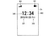
電子機器1の動作モードが通常モードである場合、つまり表示部120の表示モードが第2表示モードである場合には、様々な画面が表示領域2aに表示される。表示部120の表示モードが第2表示モードである場合には、表示領域2aには、例えば、ホーム画面及びロック画面が表示される。図5は、ホーム画面300の一例を示す図である。図6は、ロック画面400の一例を示す図である。  When the operation mode of theelectronic device 1 is the normal mode, that is, when the display mode of thedisplay unit 120 is the second display mode, various screens are displayed in thedisplay area 2a. When the display mode of thedisplay unit 120 is the second display mode, for example, a home screen and a lock screen are displayed in thedisplay area 2a. FIG. 5 is a diagram illustrating an example of thehome screen 300. FIG. 6 is a diagram illustrating an example of thelock screen 400.

図5に示されるように、ホーム画面300には、電池240の現在の容量を示す電池残量アイコン301と、計時部220が計時する現在の時刻302と、無線通信部110での電波の受信状況を示す受信状況アイコン(電波状況アイコンともよばれる)303とが示される。さらに、ホーム画面300には、アプリケーションに対応し、対応するアプリケーションを実行するための図形(以後、「アプリケーションアイコン」と呼ぶ)305が示される。  As shown in FIG. 5, on thehome screen 300, the battery remainingamount icon 301 indicating the current capacity of thebattery 240, thecurrent time 302 measured by thetimer unit 220, and reception of radio waves by the wireless communication unit 110 A reception status icon (also referred to as a radio wave status icon) 303 indicating the status is shown. Further, thehome screen 300 shows a graphic (hereinafter referred to as “application icon”) 305 corresponding to the application and for executing the corresponding application.

図5の例では、9個のアプリケーションアイコン305が示されている。図5の例では、9個のアプリケーションアイコン305に対して同一の符号を付しているが、9個のアプリケーションアイコン305のそれぞれは、別々のアプリケーションに対応している。ユーザが複数のアプリケーションアイコン305のうちの一つに対して所定の操作を行うと、制御部100は、操作されたアプリケーションアイコン305に対応するアプリケーションを記憶部103から読み出して実行する。これにより、ユーザは、アプリケーションアイコン305を操作することによって、操作されたアプリケーションアイコン305に対応するアプリケーションを電子機器1に実行させることができる。例えば、ユーザが、複数のアプリケーションアイコン305のうち、通話アプリケーションに対応する一つのアプリケーションアイコン305を操作すると、電子機器1では通話アプリケーションが実行される。またユーザが、複数のアプリケーションアイコン305のうち、カメラアプリケーションに対応する一つのアプリケーションアイコン305を操作すると、電子機器1ではカメラアプリケーションが実行される。アプリケーションアイコン305は、表示領域2aに表示されるソフトウェアボタンであるともいえる。  In the example of FIG. 5, nineapplication icons 305 are shown. In the example of FIG. 5, the same reference numerals are assigned to the nineapplication icons 305, but each of the nineapplication icons 305 corresponds to a different application. When the user performs a predetermined operation on one of the plurality ofapplication icons 305, thecontrol unit 100 reads the application corresponding to the operatedapplication icon 305 from thestorage unit 103 and executes the application. Accordingly, the user can cause theelectronic device 1 to execute an application corresponding to the operatedapplication icon 305 by operating theapplication icon 305. For example, when the user operates oneapplication icon 305 corresponding to the call application among the plurality ofapplication icons 305, the call application is executed in theelectronic device 1. When the user operates oneapplication icon 305 corresponding to the camera application among the plurality ofapplication icons 305, the camera application is executed in theelectronic device 1. It can be said that theapplication icon 305 is a software button displayed in thedisplay area 2a.

アプリケーションアイコン305に対する操作としては、例えば、当該アプリケーションアイコン305に対して、ユーザが指等の操作子を近づけた後、当該操作子を遠ざける操作が考えられる。また、アプリケーションアイコン305に対する操作としては、例えば、当該アプリケーションアイコン305に対して、ユーザが指等の操作子を接触させた後、当該操作子を遠ざける操作が考えられる。これらの操作は、いわゆるタップ操作と呼ばれる。なお、このタップ操作による操作は、アプリケーションアイコン305に対する操作以外にも、表示領域2aに表示される各種情報に対する操作として使用される。  As an operation for theapplication icon 305, for example, an operation in which the user moves an operator such as a finger closer to theapplication icon 305 and then moves the operator away from theapplication icon 305 can be considered. As an operation on theapplication icon 305, for example, an operation in which the user touches theapplication icon 305 with an operator such as a finger and then moves the operator away. These operations are called so-called tap operations. The operation by the tap operation is used as an operation for various information displayed in thedisplay area 2a in addition to the operation for theapplication icon 305.

図6に示されるように、ロック画面400には、ホーム画面300と同様に、電池残量アイコン301及び受信状況アイコン303が示される。またロック画面400には、計時部220が計時する現在の時刻306及び現在の日付307と、現在の曜日308とが示される。ロック画面400において、時刻306は、例えば、ホーム画面300での時刻302とは異なる位置において、当該時刻302よりも大きく示される。  As shown in FIG. 6, thelock screen 400 shows a remainingbattery level icon 301 and areception status icon 303 as in thehome screen 300. Further, thelock screen 400 shows thecurrent time 306 and thecurrent date 307 that thetime measuring unit 220 measures, and the current day of theweek 308. In thelock screen 400, thetime 306 is shown larger than thetime 302 at a position different from thetime 302 on thehome screen 300, for example.

電子機器1の通常モードには、記憶部103内の複数のアプリケーションのうち、特定のアプリケーション(例えば通話アプリケーション及びカメラアプリケーション)以外のアプリケーション、あるいは記憶部103内のすべてのアプリケーションを、ユーザが電子機器1に実行させることができないロックモードが含まれる。電子機器1の動作モードがロックモードである場合には、ユーザは、記憶部103内の複数のアプリケーションのうち、特定のアプリケーション以外の各アプリケーションについて、あるいは記憶部103内のすべてのアプリケーションのそれぞれについて、当該アプリケーションの実行を電子機器1に指示することができない。また、ロックモードで動作する電子機器1が実行するアプリケーションにおいて、一部の機能が制限される場合がある。例えば、ロックモードで動作する電子機器1が実行する通話アプリケーションでの通話の発信機能において、特定の電話番号以外への通話の発信が制限される。  In the normal mode of theelectronic device 1, the user selects an application other than a specific application (for example, a call application and a camera application) among all the applications in thestorage unit 103 or all applications in thestorage unit 103. 1 includes a lock mode that cannot be executed. When the operation mode of theelectronic device 1 is the lock mode, the user selects each application other than the specific application among the plurality of applications in thestorage unit 103 or each of all the applications in thestorage unit 103. Theelectronic device 1 cannot be instructed to execute the application. In addition, some functions may be limited in an application executed by theelectronic device 1 operating in the lock mode. For example, in a call origination function in a call application executed by theelectronic device 1 operating in the lock mode, the origination of a call to a phone number other than a specific phone number is restricted.

このように、電子機器1の動作モードがロックモードである場合には、電子機器1の機能の少なくとも一部が制限される。ロックモードは、ユーザの意図しない操作によって起こる誤動作を抑制するために用いることができる。ロック画面400は、電子機器1の動作モードがロックモードであることを通知する画面であって、電子機器1の動作モードがロックモードであるときに、表示領域2aに表示される。  Thus, when the operation mode of theelectronic device 1 is the lock mode, at least a part of the functions of theelectronic device 1 is restricted. The lock mode can be used to suppress malfunctions caused by operations not intended by the user. Thelock screen 400 is a screen for notifying that the operation mode of theelectronic device 1 is the lock mode, and is displayed in thedisplay area 2a when the operation mode of theelectronic device 1 is the lock mode.

電子機器1の動作モードがスリープモードである場合に、電源ボタン14aが操作されたときと、ホームボタン14cが操作されたとき、スリープモードが解除されて、電子機器1の動作モードはロックモードとなり、表示領域2aにロック画面400が表示される。  When the operation mode of theelectronic device 1 is the sleep mode, when thepower button 14a is operated and when thehome button 14c is operated, the sleep mode is canceled and the operation mode of theelectronic device 1 becomes the lock mode. Thelock screen 400 is displayed in thedisplay area 2a.

また、電子機器1の動作モードが通常モードであって、ロックモードでない場合に、ホームボタン14cが操作されると、表示領域2aにはホーム画面300が表示される。  When the operation mode of theelectronic device 1 is the normal mode and not the lock mode, when thehome button 14c is operated, thehome screen 300 is displayed in thedisplay area 2a.

表示領域2aにロック画面400が表示されている場合に、ユーザが電子機器1に対して所定の操作を行うと、電子機器1ではロックモードが解除されて、表示領域2aの表示はロック画面400から他の画面、例えばホーム画面300に切り替わる。以後、通常モードにおいて、ロックモードが解除されている状態を「非ロックモード」と呼ぶ。  When thelock screen 400 is displayed in thedisplay area 2a and the user performs a predetermined operation on theelectronic device 1, the lock mode is released in theelectronic device 1, and the display in thedisplay area 2a is displayed on thelock screen 400. To another screen, for example, thehome screen 300. Hereinafter, the state in which the lock mode is released in the normal mode is referred to as “non-lock mode”.

<ユーザ認証>
制御部100は、指紋センサ200での指紋の検出結果に基づいて、ユーザ認証を行うことが可能である。制御部100は、ユーザ認証を行う認証処理部として機能する。
<User authentication>
Thecontrol unit 100 can perform user authentication based on the result of fingerprint detection by thefingerprint sensor 200. Thecontrol unit 100 functions as an authentication processing unit that performs user authentication.

制御部100は、例えば、電子機器1の動作モードがロックモードであるときにユーザ認証を行う。制御部100は、電子機器1の動作モードがロックモードであるときに、ユーザ認証に成功したと判定すると、電子機器1の動作モードをロックモードから非ロックモードに切り替える。つまり、ロックモードが解除される。そして、表示領域2aにはロック画面400以外の表示画面(例えば、ホーム画面300あるいはアプリケーション実行時の表示画面など)が表示される。  For example, thecontrol unit 100 performs user authentication when the operation mode of theelectronic device 1 is the lock mode. When thecontrol unit 100 determines that the user authentication is successful when the operation mode of theelectronic device 1 is the lock mode, thecontrol unit 100 switches the operation mode of theelectronic device 1 from the lock mode to the non-lock mode. That is, the lock mode is released. In thedisplay area 2a, a display screen other than the lock screen 400 (for example, thehome screen 300 or a display screen during application execution) is displayed.

制御部100は、ユーザ認証を行う際、まず、指紋センサ200から指紋の検出結果として出力される指紋画像から、当該指紋画像が示す検出指紋の特徴を示す特徴点を抽出する。特徴点としては、例えば、指紋の稜線(凸部)の端点及び分岐点の位置、当該稜線の太さなどが使用される。そして、制御部100は、抽出した特徴点と、記憶部103に記憶されている基準特徴点とを比較する。基準特徴点は、正規のユーザ(例えば電子機器1の所有者)の指紋を示す指紋画像から抽出された特徴点である。  When performing the user authentication, thecontrol unit 100 first extracts a feature point indicating the feature of the detected fingerprint indicated by the fingerprint image from the fingerprint image output as the fingerprint detection result from thefingerprint sensor 200. As the feature points, for example, the positions of the end points and branch points of the ridgeline (convex part) of the fingerprint, the thickness of the ridgeline, and the like are used. Then, thecontrol unit 100 compares the extracted feature points with the reference feature points stored in thestorage unit 103. The reference feature point is a feature point extracted from a fingerprint image indicating a fingerprint of an authorized user (for example, the owner of the electronic device 1).

制御部100は、抽出した特徴点と基準特徴点とを比較した結果、両者が類似する場合には、ユーザ認証が成功であると判定する。つまり、制御部100は、指紋センサ200が検出した指紋を有するユーザが正規のユーザであると判定する。一方で、制御部100は、抽出した特徴点と基準特徴点とが類似しない場合には、ユーザ認証に失敗したと判定する。つまり、制御部100は、指紋センサ200が検出した指紋を有するユーザが非正規のユーザであると判定する。  As a result of comparing the extracted feature points with the reference feature points, thecontrol unit 100 determines that the user authentication is successful when both are similar. That is, thecontrol unit 100 determines that the user having the fingerprint detected by thefingerprint sensor 200 is a regular user. On the other hand, if the extracted feature point and the reference feature point are not similar, thecontrol unit 100 determines that user authentication has failed. That is, thecontrol unit 100 determines that the user having the fingerprint detected by thefingerprint sensor 200 is an unauthorized user.

電子機器1の通常モードには、ユーザの指紋を電子機器1に登録するための指紋登録モードが含まれる。電子機器1は、非ロックモードにおいて、表示領域2aに対して所定の操作が行われると、指紋登録モードで動作する。指紋登録モードにおいて、正規のユーザが自身の手の指を指紋検出領域201上に置くと、指紋センサ200は当該指の指紋を検出し、検出指紋を示す指紋画像を出力する。制御部100は、指紋センサ200からの指紋画像から特徴点を抽出し、抽出した特徴点を基準特徴点として記憶部103に記憶する。これにより、正規のユーザの指紋の特徴を示す基準特徴点が記憶部103に記憶される。つまり、正規のユーザの指紋が電子機器1に登録される。  The normal mode of theelectronic device 1 includes a fingerprint registration mode for registering a user's fingerprint in theelectronic device 1. Theelectronic device 1 operates in the fingerprint registration mode when a predetermined operation is performed on thedisplay area 2a in the non-lock mode. In the fingerprint registration mode, when a legitimate user places his / her finger on thefingerprint detection area 201, thefingerprint sensor 200 detects the fingerprint of the finger and outputs a fingerprint image indicating the detected fingerprint. Thecontrol unit 100 extracts feature points from the fingerprint image from thefingerprint sensor 200 and stores the extracted feature points in thestorage unit 103 as reference feature points. Thus, the reference feature points indicating the features of the legitimate user's fingerprint are stored in thestorage unit 103. That is, the legitimate user's fingerprint is registered in theelectronic device 1.

<指紋センサの検出モードについて>
指紋センサ200は、指紋検出領域201を触るユーザの指の指紋を検出しない第1検出モードと、当該指紋を検出する第2検出モードとを有する。指紋センサ200の検出モードは、制御部100によって設定される。第1検出モードでは、第2検出モードよりも指紋センサ200の消費電力が低減する。ユーザ認証は、指紋センサ200の検出モードが第2検出モードであるときに行われる。
<Fingerprint sensor detection mode>
Thefingerprint sensor 200 has a first detection mode in which the fingerprint of the user's finger touching thefingerprint detection area 201 is not detected, and a second detection mode in which the fingerprint is detected. The detection mode of thefingerprint sensor 200 is set by thecontrol unit 100. In the first detection mode, the power consumption of thefingerprint sensor 200 is reduced compared to the second detection mode. User authentication is performed when the detection mode of thefingerprint sensor 200 is the second detection mode.

電子機器1では、その消費電力を低減するために、電子機器1の動作モードがスリープモードであるときに、表示領域2aに各種情報を表示する表示機能を含む一部の機能を停止する。例えば制御部100は、電子機器1の動作モードがスリープモードであるときに、指紋センサ200の検出モードを第1検出モードに設定する場合がある。  In theelectronic device 1, in order to reduce the power consumption, when the operation mode of theelectronic device 1 is the sleep mode, some functions including a display function for displaying various information in thedisplay area 2a are stopped. For example, thecontrol unit 100 may set the detection mode of thefingerprint sensor 200 to the first detection mode when the operation mode of theelectronic device 1 is the sleep mode.

電子機器1がスリープモードで動作しているときに、指紋センサ200の検出モードが第1検出モードに設定される場合には、ユーザ認証を行う前に、例えば電源ボタン14aなどを操作してスリープモードを解除して、指紋センサ200の検出モードを第1検出モードから第2検出モードに切り替える必要がある。この検出モードの切り替えには、例えば、1秒程度の時間を有する。このため、ユーザ認証を開始するまでに時間がかかってしまう場合がある。  When the detection mode of thefingerprint sensor 200 is set to the first detection mode when theelectronic device 1 is operating in the sleep mode, the user operates thepower button 14a or the like before performing user authentication. It is necessary to cancel the mode and switch the detection mode of thefingerprint sensor 200 from the first detection mode to the second detection mode. The detection mode switching has a time of about 1 second, for example. For this reason, it may take time to start user authentication.

そこで、電子機器1がスリープモードで動作している場合でも、指紋センサ200の検出モードを第2検出モードに設定することが考えられる。この場合には、ユーザの指が指紋検出領域201に触れたときに当該指の指紋が検出され、ユーザ認証をすぐに開始することができる。このように、指紋センサ200の検出モードを第1検出モードから第2検出モードに切り替える時間を必要としないことから、ユーザ認証を開始するまでの時間を短くすることができる。  Therefore, even when theelectronic device 1 is operating in the sleep mode, it is conceivable to set the detection mode of thefingerprint sensor 200 to the second detection mode. In this case, when the user's finger touches thefingerprint detection area 201, the fingerprint of the finger is detected, and user authentication can be started immediately. Thus, since the time for switching the detection mode of thefingerprint sensor 200 from the first detection mode to the second detection mode is not required, the time until the user authentication is started can be shortened.

しかしながら、電子機器1がスリープモードで動作している期間、指紋センサ200の検出モードが第2検出モードに設定されている場合には、電子機器1の消費電力が増大する。  However, when theelectronic device 1 is operating in the sleep mode and the detection mode of thefingerprint sensor 200 is set to the second detection mode, the power consumption of theelectronic device 1 increases.

本実施の形態では、電子機器1の動作モードがスリープモードであるときに、所定の条件を満たす場合には、指紋センサ200の検出モードが第1検出モードに設定され、所定の条件を満たさない場合には、指紋センサ200の検出モードが第2検出モードに設定される。例えば、電子機器1の動作モードがスリープモードであるときに、ユーザ認証を行う可能性が低いと考えられるような場合には、指紋センサ200の検出モードが第1検出モードに設定され、それ以外の場合には、指紋センサ200の検出モードが第2検出モードに設定される。これにより、電子機器1の消費電力の低減と、ユーザ認証を開始するまでの時間の短縮とを実現することができる。  In the present embodiment, when the operation mode of theelectronic device 1 is the sleep mode and the predetermined condition is satisfied, the detection mode of thefingerprint sensor 200 is set to the first detection mode and does not satisfy the predetermined condition. In this case, the detection mode of thefingerprint sensor 200 is set to the second detection mode. For example, when the operation mode of theelectronic device 1 is the sleep mode, when it is considered that the possibility of performing user authentication is low, the detection mode of thefingerprint sensor 200 is set to the first detection mode. In this case, the detection mode of thefingerprint sensor 200 is set to the second detection mode. Thereby, reduction of the power consumption of theelectronic device 1 and the shortening of time until user authentication is started are realizable.

以下に、電子機器1の動作モードがスリープモードであるときに、制御部100が指紋センサ200の検出モードを設定する動作について説明する。図7は、当該動作の一例を示すフローチャートである。  Hereinafter, an operation in which thecontrol unit 100 sets the detection mode of thefingerprint sensor 200 when the operation mode of theelectronic device 1 is the sleep mode will be described. FIG. 7 is a flowchart showing an example of the operation.

図7に示されるように、ステップS1において電子機器1がスリープモードで動作する場合に、ステップS2において、制御部100は、計時部220が計時する現在時刻が所定の時間帯に含まれるか否かの第1判定を行う。ステップS2において、計時部220が計時する現在時刻が所定の時間帯に含まれると判定される場合には、ステップS5が実行される。ステップS5において、制御部100は、指紋センサ200の検出モードを第1検出モードに設定する。  As shown in FIG. 7, when theelectronic device 1 operates in the sleep mode in step S1, in step S2, thecontrol unit 100 determines whether or not the current time measured by thetime measuring unit 220 is included in the predetermined time zone. The first determination is performed. If it is determined in step S2 that the current time measured by thetime measuring unit 220 is included in the predetermined time zone, step S5 is executed. In step S5, thecontrol unit 100 sets the detection mode of thefingerprint sensor 200 to the first detection mode.

ユーザの行動パターンにおいて、電子機器1を使用しない時間帯がほぼ決まっている場合がある。例えば、午前0時から午前6時の間の時間帯では、ユーザが就寝している可能性が高く、電子機器1を使用しない可能性が高いことがある。そこで、この時間帯に電子機器1がスリープモードであるときには、ユーザ認証が行われる可能性が低いものとして、制御部100は、指紋センサ200の検出モードを第1検出モードに設定する。これにより、電子機器1の消費電力を低減することができる。  In a user's action pattern, the time zone when theelectronic device 1 is not used may be almost determined. For example, in the time zone between midnight and 6:00 am, there is a high possibility that the user is sleeping and there is a high possibility that theelectronic device 1 is not used. Therefore, when theelectronic device 1 is in the sleep mode during this time period, thecontrol unit 100 sets the detection mode of thefingerprint sensor 200 to the first detection mode on the assumption that user authentication is unlikely. Thereby, the power consumption of theelectronic device 1 can be reduced.

電子機器1を使用しない可能性が高い時間帯は、例えば、ユーザの操作によって、電子機器1に入力されて記憶部103に記憶される。なお、制御部100は、例えば、スリープ解除操作が行われる度に、当該操作が行われた時刻を記憶部103に記憶しておき、当該時刻に基づいて、ユーザ認証が行われる可能性が低い時間帯を予測しても良い。  The time zone in which there is a high possibility that theelectronic device 1 is not used is input to theelectronic device 1 and stored in thestorage unit 103 by a user operation, for example. Note that thecontrol unit 100 stores, for example, the time when the operation is performed in thestorage unit 103 every time the sleep release operation is performed, and the user authentication is less likely to be performed based on the time. The time zone may be predicted.

ステップS2において、計時部220が計時する現在時刻が所定の時間帯に含まれないと判定される場合には、ステップS3が実行される。ステップS3において、制御部100は、電子機器1が静止中であるか否かの第2判定を行う。具体的には、制御部100は、加速度センサ210が検出する加速度が所定時間の間、所定値以下である場合に、電子機器1が静止していると判定する。ステップS3において、電子機器1が静止中であると判定される場合には、ステップS5において、制御部100は、指紋センサ200の検出モードを第1検出モードに設定する。  If it is determined in step S2 that the current time measured by thetimer unit 220 is not included in the predetermined time zone, step S3 is executed. In step S3, thecontrol unit 100 performs the second determination as to whether or not theelectronic device 1 is stationary. Specifically, thecontrol unit 100 determines that theelectronic device 1 is stationary when the acceleration detected by theacceleration sensor 210 is equal to or less than a predetermined value for a predetermined time. If it is determined in step S3 that theelectronic device 1 is stationary, in step S5, thecontrol unit 100 sets the detection mode of thefingerprint sensor 200 to the first detection mode.

スリープモードで動作する電子機器1が静止中である場合には、ユーザが電子機器1を使用していない可能性が高い。そこで、電子機器1の動作モードがスリープモードであるときに、電子機器1が静止していると判定される場合には、ユーザ認証が行われる可能性が低いものとして、制御部100は、指紋センサ200の検出モードを第1検出モードに設定する。これにより、電子機器1の消費電力を低減することができる。  When theelectronic device 1 operating in the sleep mode is stationary, it is highly likely that the user is not using theelectronic device 1. Therefore, when it is determined that theelectronic device 1 is stationary when the operation mode of theelectronic device 1 is the sleep mode, thecontrol unit 100 determines that user authentication is unlikely to be performed, The detection mode of thesensor 200 is set to the first detection mode. Thereby, the power consumption of theelectronic device 1 can be reduced.

ステップS3において、電子機器1が静止中でないと判定される場合には、ステップS4が実行される。ステップS4において、制御部100は、ユーザが歩行動作中であるか否かの第3判定を行う。具体的には、制御部100は、歩数計測部230がユーザの歩数を計測している場合には、ユーザが歩行動作中であると判定する。  If it is determined in step S3 that theelectronic device 1 is not stationary, step S4 is executed. In step S4, thecontrol unit 100 performs a third determination as to whether or not the user is walking. Specifically, thecontrol unit 100 determines that the user is walking when thestep counting unit 230 is measuring the number of steps of the user.

ユーザが歩行動作中である場合には、ユーザが電子機器1を使用していない可能性が高い。そこで、電子機器1の動作モードがスリープモードであるときに、ユーザが歩行動作中であると判定される場合には、ユーザ認証が行われる可能性が低いものとして、制御部100は、指紋センサ200の検出モードを第1検出モードに設定する。これにより、電子機器1の消費電力を低減することができる。  When the user is walking, there is a high possibility that the user is not using theelectronic device 1. Therefore, when it is determined that the user is walking while the operation mode of theelectronic device 1 is the sleep mode, thecontrol unit 100 determines that user authentication is unlikely to be performed, The 200 detection mode is set to the first detection mode. Thereby, the power consumption of theelectronic device 1 can be reduced.

なお、制御部100は、歩数計測部230での計測結果に基づいて、ユーザが歩行動作中であると判定するのではなく、加速度センサ210が検出する加速度検出結果に基づいて電子機器1の空間的な動きを検出し、当該動きが所定の動きであると判定される場合に、ユーザが歩行動作中であると判定しても良い。  Note that thecontrol unit 100 does not determine that the user is walking, based on the measurement result of the stepcount measurement unit 230, but based on the acceleration detection result detected by theacceleration sensor 210. When a specific movement is detected and it is determined that the movement is a predetermined movement, it may be determined that the user is walking.

ステップS4において、ユーザが歩行動作中でないと判定される場合には、ステップS6が実行される。ステップS6において、制御部100は、指紋センサ200の検出モードを第2検出モードに設定する。  If it is determined in step S4 that the user is not walking, step S6 is executed. In step S6, thecontrol unit 100 sets the detection mode of thefingerprint sensor 200 to the second detection mode.

ステップS5が実行された後と、ステップS6が実行された後には、ステップS2が実行される。以後、電子機器1は同様に動作する。  After step S5 is executed and after step S6 is executed, step S2 is executed. Thereafter, theelectronic device 1 operates in the same manner.

このように、電子機器1の動作モードがスリープモードであるときに、図7で示したステップS2〜S4において否定的な判定がなされる場合、つまりユーザ認証が行われる可能性が低くないと考えられる場合には、制御部100は、指紋センサの検出モードを第2検出モードに設定する。これにより、制御部100は、ユーザの指が指紋検出領域201に触れて当該指紋が検出されたときにユーザ認証を開始することができる。  Thus, when the operation mode of theelectronic device 1 is the sleep mode, if negative determination is made in steps S2 to S4 illustrated in FIG. 7, that is, the possibility that user authentication is performed is not low. In the case where it is possible, thecontrol unit 100 sets the detection mode of the fingerprint sensor to the second detection mode. Thus, thecontrol unit 100 can start user authentication when the user's finger touches thefingerprint detection area 201 and the fingerprint is detected.

なお、ステップS2〜S4の実行順序は図7に示した順序に限られない。また、ステップS2が、ステップS3及びステップS4の前に実行される場合には、ステップS2において、計時部220が計時する現在時刻が所定時間帯に含まれると判定される場合には、加速度センサ210及び歩数計測部230の機能を停止しても良い。これにより、消費電力をより低減することができる。  The execution order of steps S2 to S4 is not limited to the order shown in FIG. Further, when step S2 is executed before steps S3 and S4, if it is determined in step S2 that the current time measured by thetime measuring unit 220 is included in the predetermined time zone, the acceleration sensor The functions of 210 and the stepcount measuring unit 230 may be stopped. Thereby, power consumption can be reduced more.

また、ステップS2〜S4のうち少なくとも一つの処理が実行されれば良い。  Further, at least one of the steps S2 to S4 may be executed.

<指紋センサが第1検出モードである場合でのユーザ認証>
以下に、電子機器1の動作モードがスリープであるときに、指紋センサ200の検出モードが第1検出モードである場合での電子機器1の動作について説明する。図8は、当該動作の一例を示すフローチャートである。
<User authentication when fingerprint sensor is in first detection mode>
Hereinafter, the operation of theelectronic device 1 when the detection mode of thefingerprint sensor 200 is the first detection mode when the operation mode of theelectronic device 1 is sleep will be described. FIG. 8 is a flowchart showing an example of the operation.

図8に示されるように、ステップS11において電子機器1の動作モードがスリープモードであって、指紋センサ200の検出モードが第1検出モードである場合に、ステップS12において、制御部100は、スリープ解除操作、例えば電源ボタン14aへの操作を検出すると、ステップS13においてスリープモードを解除する。  As shown in FIG. 8, when the operation mode of theelectronic device 1 is the sleep mode and the detection mode of thefingerprint sensor 200 is the first detection mode in step S11, thecontrol unit 100 sleeps in step S12. When a release operation, for example, an operation on thepower button 14a is detected, the sleep mode is released in step S13.

スリープモードが解除されると、ステップS14において、制御部100は、電子機器1の動作モードをロックモードに設定する。そして、ステップS15において、表示部120は、表示領域2aにロック画面を表示する。また、ステップS15において、制御部100は、指紋センサ200の検出モードを第1検出モードから第2検出モードに切り替える。  When the sleep mode is canceled, in step S14, thecontrol unit 100 sets the operation mode of theelectronic device 1 to the lock mode. In step S15, thedisplay unit 120 displays a lock screen in thedisplay area 2a. In step S15, thecontrol unit 100 switches the detection mode of thefingerprint sensor 200 from the first detection mode to the second detection mode.

指紋センサ200の検出モードが第2検出モードになると、制御部100は、指紋検出待ち状態となる。ステップS16において、指紋センサ200が指紋検出領域201を触るユーザの指の指紋を検出すると、ステップS17が実行される。  When the detection mode of thefingerprint sensor 200 becomes the second detection mode, thecontrol unit 100 enters a fingerprint detection waiting state. In step S16, when thefingerprint sensor 200 detects the fingerprint of the user's finger touching thefingerprint detection area 201, step S17 is executed.

ステップS17において、制御部100は、ステップS16での検出指紋に基づいて、ユーザ認証を行う。ステップS17でのユーザ認証処理が終了すると、ステップS18において、制御部100は、ユーザ認証が成功した否かを判断する。  In step S17, thecontrol unit 100 performs user authentication based on the detected fingerprint in step S16. When the user authentication process in step S17 ends, in step S18, thecontrol unit 100 determines whether the user authentication is successful.

ステップS18において、ユーザ認証が成功したと判定されると、ステップS19が実行される。ステップS19において、制御部100は、ロックモードを解除する。ロックモードが解除されると、表示部120は、ロック画面以外の画面、例えばホーム画面を表示する。  If it is determined in step S18 that the user authentication is successful, step S19 is executed. In step S19, thecontrol unit 100 releases the lock mode. When the lock mode is released, thedisplay unit 120 displays a screen other than the lock screen, for example, a home screen.

一方、ステップS18において、ユーザ認証が失敗したと判定されると、ステップS20が実行される。ステップS20において、表示部120は、ユーザ認証の失敗を通知するための認証失敗通知情報をロック画面に表示する。図9は、認証失敗通知情報410を含むロック画面400の一例を示す図である。図9の例では、認証失敗通知情報410として「ユーザ認証に失敗しました」という文字列が表示されている。  On the other hand, if it is determined in step S18 that the user authentication has failed, step S20 is executed. In step S20, thedisplay unit 120 displays authentication failure notification information for notifying user authentication failure on the lock screen. FIG. 9 is a diagram illustrating an example of thelock screen 400 including the authenticationfailure notification information 410. In the example of FIG. 9, a character string “user authentication failed” is displayed as the authenticationfailure notification information 410.

ステップS20の後、制御部100は、再度指紋検出待ち状態となり、ステップS16が実行される。以後、電子機器1は同様に動作する。  After step S20, thecontrol unit 100 again enters the fingerprint detection waiting state, and step S16 is executed. Thereafter, theelectronic device 1 operates in the same manner.

このように、電子機器1の動作モードがスリープモードであって、指紋センサ200の検出モードが第1検出モードである場合には、ユーザは、ユーザ認証を行う前に、スリープ解除操作を行って、指紋センサ200の検出モードを第1検出モードから第2検出モードに切り替える必要がある。そのため、ユーザ認証をすぐに開始することができない。  As described above, when the operation mode of theelectronic device 1 is the sleep mode and the detection mode of thefingerprint sensor 200 is the first detection mode, the user performs a sleep release operation before performing user authentication. It is necessary to switch the detection mode of thefingerprint sensor 200 from the first detection mode to the second detection mode. Therefore, user authentication cannot be started immediately.

<指紋センサが第2検出モードである場合でのユーザ認証>
次に、電子機器1の動作モードがスリープモードであるときに、指紋センサ200の検出モードが第2検出モードである場合での電子機器1の動作について説明する。図10は、当該動作の一例を示すフローチャートである。
<User authentication when fingerprint sensor is in second detection mode>
Next, the operation of theelectronic device 1 when the operation mode of theelectronic device 1 is the sleep mode and the detection mode of thefingerprint sensor 200 is the second detection mode will be described. FIG. 10 is a flowchart showing an example of the operation.

図10に示されるように、ステップS21において電子機器1の動作モードがスリープモードであって、指紋センサ200の検出モードが第2検出モードである場合には、制御部100は、指紋検出待ち状態となっている。ユーザがスリープモードを解除するために電源ボタン14aを操作しようとして操作領域141に指を触れたとき、ステップS22において、指紋センサ200は、当該指の指紋を検出する。  As shown in FIG. 10, when the operation mode of theelectronic device 1 is the sleep mode and the detection mode of thefingerprint sensor 200 is the second detection mode in step S21, thecontrol unit 100 waits for the fingerprint detection. It has become. When the user touches theoperation area 141 in order to operate thepower button 14a to cancel the sleep mode, thefingerprint sensor 200 detects the fingerprint of the finger in step S22.

指紋センサ200が指紋を検出すると、ステップS23において、制御部100は、ステップS22での検出指紋に基づいて、ユーザ認証を開始する。ここで、ユーザが電源ボタン14aを操作しなくても、操作領域141に指を触れて当該指の指紋が検出されるとユーザ認証が開始される。そしてそのユーザ認証結果は、記憶部103に記憶される。  When thefingerprint sensor 200 detects a fingerprint, in step S23, thecontrol unit 100 starts user authentication based on the detected fingerprint in step S22. Here, even if the user does not operate thepower button 14a, the user authentication is started when the finger of theoperation area 141 is touched and the fingerprint of the finger is detected. The user authentication result is stored in thestorage unit 103.

ステップS24において、制御部100は、スリープ解除操作、例えば、電源ボタン14aへの操作を検出すると、ステップS25においてスリープモードを解除する。  In step S24, when thecontrol unit 100 detects a sleep cancel operation, for example, an operation on thepower button 14a, thecontrol unit 100 cancels the sleep mode in step S25.

ステップS23で開始されるユーザ認証処理が終了する前であっても、ステップS24を実行することができる。この場合、ステップS24及びステップS25の処理が実行されている間にもユーザ認証が行われる。  Even before the user authentication process started in step S23 ends, step S24 can be executed. In this case, user authentication is also performed while the processing of step S24 and step S25 is being executed.

スリープモードが解除されると、ステップS26において、制御部100は、ステップS23で開始したユーザ認証の結果に基づいて、ユーザ認証が成功したか否かを判定する。  When the sleep mode is canceled, in step S26, thecontrol unit 100 determines whether the user authentication is successful based on the result of the user authentication started in step S23.

ステップS26において、ユーザ認証が成功したと判定されると、ステップS27が実行される。ステップS27において、制御部100は、電子機器1の動作モードを非ロックモードに設定する。ステップS26においてユーザ認証が成功したと判定される場合には、電子機器1の動作モードはロックモードになることなく、スリープモードから非ロックモードに切り替わる。つまり、表示領域2aにロック画面が表示されることなく、電子機器1の動作モードがスリープモードから非ロックモードに切り替わる。  If it is determined in step S26 that the user authentication is successful, step S27 is executed. In step S27, thecontrol unit 100 sets the operation mode of theelectronic device 1 to the non-lock mode. If it is determined in step S26 that the user authentication is successful, the operation mode of theelectronic device 1 is switched from the sleep mode to the non-lock mode without entering the lock mode. That is, the operation mode of theelectronic device 1 is switched from the sleep mode to the non-lock mode without displaying the lock screen in thedisplay area 2a.

一方、ステップS26において、ユーザ認証が失敗したと判定されると、ステップS28において、制御部100は、電子機器1の動作モードをロックモードに設定する。  On the other hand, if it is determined in step S26 that the user authentication has failed, in step S28, thecontrol unit 100 sets the operation mode of theelectronic device 1 to the lock mode.

電子機器1の動作モードがロックモードに設定されると、ステップS29において、表示部120は、ユーザ認証の失敗を通知するための認証失敗通知情報を含むロック画面を表示する。例えば、表示部120は、図9で示した認証失敗通知情報410を含むロック画面400を表示する。  When the operation mode of theelectronic device 1 is set to the lock mode, in step S29, thedisplay unit 120 displays a lock screen including authentication failure notification information for notifying user authentication failure. For example, thedisplay unit 120 displays thelock screen 400 including the authenticationfailure notification information 410 illustrated in FIG.

ステップS29の後、制御部100は、再度指紋検出待ち状態となる。ステップS30において、指紋センサ200が指紋検出領域201を触るユーザの指の指紋を再度検出すると、ステップS31が実行される。  After step S29, thecontrol unit 100 again enters the fingerprint detection waiting state. In step S30, when thefingerprint sensor 200 detects again the fingerprint of the user's finger touching thefingerprint detection area 201, step S31 is executed.

ステップS31において、制御部100は、ステップS30での検出指紋に基づいて、再度ユーザ認証を行う。ステップS31でのユーザ認証処理が終了すると、ステップS32において、制御部100は、ユーザ認証が成功した否かを判断する。  In step S31, thecontrol unit 100 performs user authentication again based on the detected fingerprint in step S30. When the user authentication process in step S31 ends, in step S32, thecontrol unit 100 determines whether the user authentication is successful.

ステップS32において、ユーザ認証が成功したと判定されると、ステップS27において、制御部100は、電子機器1の動作モードをロックモードから非ロックモードに切り替える。  If it is determined in step S32 that the user authentication is successful, in step S27, thecontrol unit 100 switches the operation mode of theelectronic device 1 from the lock mode to the non-lock mode.

一方、ステップS32において、ユーザ認証が失敗したと判定されると、ステップS33において、認証失敗通知情報が再度表示される。  On the other hand, if it is determined in step S32 that user authentication has failed, authentication failure notification information is displayed again in step S33.

ステップS33の後、制御部100は、再度指紋検出待ち状態となり、ステップS30が実行される。以後、電子機器1は同様に動作する。  After step S33, thecontrol unit 100 again enters the fingerprint detection waiting state, and step S30 is executed. Thereafter, theelectronic device 1 operates in the same manner.

このように、電子機器1の動作モードがスリープモードであるときに、指紋センサ200の検出モードが第2検出モードに設定される場合には、ユーザの指が指紋検出領域201に触れたときに当該指の指紋が検出され、ユーザ認証を開始することができる。よって、図8で示したフローチャートと比較して、指紋センサ200の検出モードを第1検出モードから第2検出モードに切り替える処理を必要としないことから、ユーザ認証を開始するまでの時間を短くすることができる。  Thus, when the operation mode of theelectronic device 1 is the sleep mode and the detection mode of thefingerprint sensor 200 is set to the second detection mode, when the user's finger touches thefingerprint detection area 201 The fingerprint of the finger is detected, and user authentication can be started. Therefore, as compared with the flowchart shown in FIG. 8, since the process of switching the detection mode of thefingerprint sensor 200 from the first detection mode to the second detection mode is not required, the time until the user authentication is started is shortened. be able to.

また、指紋センサ200が指紋を検出してから、スリープモードが解除されるまでの間にもユーザ認証を行うことができることから、スリープモードが解除されてから、ユーザ認証の判定を行うまでの時間を短くすることができる。  Also, since user authentication can be performed during the period from when thefingerprint sensor 200 detects a fingerprint until the sleep mode is canceled, the time from when the sleep mode is canceled until the user authentication is determined. Can be shortened.

また、指紋センサ200の指紋検出領域201は、スリープ解除操作のための操作ボタンとして機能する電源ボタン14aの操作領域141に含まれることから、ユーザがスリープ解除操作を行うために電源ボタン14aの操作領域141に指を触れたときに当該指の指紋を検出することができる。これにより、ユーザ認証を開始するまでの時間をより短くすることができる。  Further, since thefingerprint detection area 201 of thefingerprint sensor 200 is included in theoperation area 141 of thepower button 14a that functions as an operation button for the sleep release operation, the user operates thepower button 14a to perform the sleep release operation. When a finger touches thearea 141, the fingerprint of the finger can be detected. Thereby, time until user authentication is started can be shortened.

また、スリープ解除操作前にユーザ認証処理が完了した場合でも、スリープ解除操作が検出されるまでスリープモードが解除されないことから、誤操作によって指紋センサ200が指紋検出動作を行って、スリープモードが解除されることを抑制することができる。また誤操作による指紋検出動作では、ユーザ認証が失敗する可能性が高いと考えられることから、誤操作によって認証失敗通知情報が表示されるのを抑制することができる。  Even when the user authentication process is completed before the sleep release operation, the sleep mode is not released until the sleep release operation is detected. Therefore, thefingerprint sensor 200 performs a fingerprint detection operation due to an erroneous operation, and the sleep mode is released. Can be suppressed. In addition, in the fingerprint detection operation due to an erroneous operation, it is considered that there is a high possibility that the user authentication will fail. Therefore, it is possible to suppress the display of the authentication failure notification information due to an erroneous operation.

<各種変形例>
以下に各種変形例について説明する。
<Various modifications>
Various modifications will be described below.

<第1変形例>
上記の例では、ユーザ認証が失敗した場合にロック画面に認証失敗通知情報が表示されていたが、スリープモードで開始したユーザ認証が失敗した場合には、ロック画面に認証失敗通知情報を表示しなくても良い。
<First Modification>
In the above example, authentication failure notification information is displayed on the lock screen when user authentication fails. However, when user authentication started in sleep mode fails, authentication failure notification information is displayed on the lock screen. It is not necessary.

図11は、本変形に係る電子機器1の動作の一例を示すフローチャートである。図11では、電子機器1の動作モードがスリープモードであって、指紋センサ200の検出モードが第2検出モードである場合での電子機器1の動作を示している。  FIG. 11 is a flowchart showing an example of the operation of theelectronic apparatus 1 according to this modification. FIG. 11 shows the operation of theelectronic device 1 when the operation mode of theelectronic device 1 is the sleep mode and the detection mode of thefingerprint sensor 200 is the second detection mode.

ステップS41〜S48の処理は、図10でのステップS21〜S28と同様であるので、繰り返しの説明は省略する。  Since the processing of steps S41 to S48 is the same as that of steps S21 to S28 in FIG. 10, repeated description will be omitted.

ステップS46において、ユーザ認証が失敗したと判定される場合には、ステップS48が実行される。ステップS48において、制御部100は、電子機器1の動作モードをロックモードに設定する。  If it is determined in step S46 that the user authentication has failed, step S48 is executed. In step S48, thecontrol unit 100 sets the operation mode of theelectronic device 1 to the lock mode.

電子機器1の動作モードがロックモードに設定されると、ステップS49において、表示部120は、ロック画面を表示する。ステップS49において表示されるロック画面には、認証失敗通知情報が含まれない。例えば、表示部120は、図6で示したロック画面400を表示する。  When the operation mode of theelectronic device 1 is set to the lock mode, thedisplay unit 120 displays a lock screen in step S49. The lock screen displayed in step S49 does not include authentication failure notification information. For example, thedisplay unit 120 displays thelock screen 400 shown in FIG.

ステップS49の後、制御部100は、再度指紋検出待ち状態となる。ステップS50において、指紋センサ200が再度指紋を検出すると、ステップS51が実行される。  After step S49, thecontrol unit 100 enters the fingerprint detection waiting state again. If thefingerprint sensor 200 detects the fingerprint again in step S50, step S51 is executed.

ステップS51において、制御部100は、ステップS50での検出指紋に基づいて、再度ユーザ認証を行う。ステップS51でのユーザ認証処理が終了すると、ステップS52において、制御部100は、ユーザ認証が成功したか否かを判定する。  In step S51, thecontrol unit 100 performs user authentication again based on the detected fingerprint in step S50. When the user authentication process in step S51 ends, in step S52, thecontrol unit 100 determines whether the user authentication is successful.

ステップS52において、ユーザ認証が成功したと判定される場合には、ステップS47において、制御部100は、ロックモードを解除して、電子機器1の動作モードを非ロックモードに設定する。  If it is determined in step S52 that the user authentication is successful, in step S47, thecontrol unit 100 cancels the lock mode and sets the operation mode of theelectronic device 1 to the non-lock mode.

一方、ステップS52において、ユーザ認証が失敗したと判定される場合には、ステップS53が実行される。ステップS53において、表示部120は、ロック画面に認証失敗通知情報を表示する。例えば、表示部120は、図9で示した認証失敗通知情報410を含むロック画面400を表示する。このように、電子機器1の動作モードがロックモードであるときに行ったユーザ認証が失敗した場合には、認証失敗通知情報がロック画面に表示される。  On the other hand, if it is determined in step S52 that the user authentication has failed, step S53 is executed. In step S53, thedisplay unit 120 displays authentication failure notification information on the lock screen. For example, thedisplay unit 120 displays thelock screen 400 including the authenticationfailure notification information 410 illustrated in FIG. Thus, when the user authentication performed when the operation mode of theelectronic device 1 is the lock mode fails, the authentication failure notification information is displayed on the lock screen.

ステップS53が実行された後、再度ステップ50以降の処理が実行される。  After step S53 is executed, the processing after step 50 is executed again.

このように、スリープモードであるときに開始したユーザ認証が失敗した場合には、認証失敗情報を含まないロック画面が表示される。これにより、ユーザは、例えば、指紋が登録されていない指で電源ボタン14aを操作することによって、認証失敗情報を含まないロック画面を表示させることができる。したがって、時刻確認などのために、単にロック画面を表示させたい場合に、認証失敗通知情報を含まないロック画面を表示させることができることから、ロック画面を確認しやすくなる。  As described above, when the user authentication started in the sleep mode fails, a lock screen not including the authentication failure information is displayed. As a result, the user can display a lock screen that does not include authentication failure information, for example, by operating thepower button 14a with a finger for which no fingerprint is registered. Therefore, when the lock screen is simply displayed for time confirmation or the like, the lock screen that does not include the authentication failure notification information can be displayed, which makes it easy to check the lock screen.

<第2変形例>
本変形例では、制御部100は、スリープ解除操作を検出する前にユーザ認証が失敗した場合に、ユーザ認証が失敗したことを通知する。図12は、本変形例に係る電子機器1の動作の一例を示すフローチャートである。図12では、電子機器1の動作モードがスリープモードであって、指紋センサ200の検出モードが第2検出モードである場合での電子機器1の動作を示している。
<Second Modification>
In this modification, thecontrol unit 100 notifies the user authentication failure when the user authentication fails before detecting the sleep release operation. FIG. 12 is a flowchart illustrating an example of the operation of theelectronic device 1 according to this modification. FIG. 12 shows the operation of theelectronic device 1 when the operation mode of theelectronic device 1 is the sleep mode and the detection mode of thefingerprint sensor 200 is the second detection mode.

ステップS61〜S63,S65〜S73での処理は、図10でのステップS21〜S23,S25〜S33での処理と同様であるので詳細な説明は省略する。  The processes in steps S61 to S63 and S65 to S73 are the same as the processes in steps S21 to S23 and S25 to S33 in FIG.

ステップ63においてユーザ認証が開始されると、ステップS64が実行される。ステップS64において、制御部100は、スリープ解除操作を検出したか否かを判定する。ステップS64において、スリープ解除操作を検出したと判定される場合には、ステップS65以降の処理が実行される。  When user authentication is started in step 63, step S64 is executed. In step S64, thecontrol unit 100 determines whether or not a sleep release operation is detected. If it is determined in step S64 that a sleep cancel operation has been detected, the processes in and after step S65 are executed.

一方、ステップS64において、スリープ解除操作が検出されないと判定される場合には、ステップS74が実行される。ステップS74において、制御部100は、ステップS63で開始したユーザ認証の結果に基づいて、ユーザ認証が成功したか否かを判定する。  On the other hand, if it is determined in step S64 that the sleep release operation is not detected, step S74 is executed. In step S74, thecontrol unit 100 determines whether the user authentication is successful based on the result of the user authentication started in step S63.

ステップS74において、ユーザ認証が成功したと判定されると、ステップS64が再度実行される。ステップS74でのユーザ認証結果は、記憶部103内に記憶される。  If it is determined in step S74 that the user authentication is successful, step S64 is executed again. The user authentication result in step S74 is stored in thestorage unit 103.

一方、ステップS74において、ユーザ認証が失敗したと判定されると、ステップS75が実行される。ステップS75において、制御部100は、ユーザ認証が失敗したことを通知する。  On the other hand, if it is determined in step S74 that the user authentication has failed, step S75 is executed. In step S75, thecontrol unit 100 notifies that user authentication has failed.

ステップS75でのユーザ認証失敗の通知は、図10に示されるステップS29及びS33での処理のようにユーザ認証失敗通知情報が表示領域2aに表示されるのではなく、表示部120以外によって通知される。例えば、ユーザ認証失敗の通知は、外部スピーカから出力される音によって行われる。なお、電子機器1がLEDなどによって構成される通知ランプを備えている場合には、通知ランプを発光させることによって、ユーザ認証失敗が通知されても良い。また、電子機器1が圧電振動素子、モータなどによって構成される振動部を備えている場合には、振動部が電子機器1を振動させることによって、ユーザ認証失敗が通知されても良い。  The user authentication failure notification in step S75 is not displayed in thedisplay area 2a as in the processing in steps S29 and S33 shown in FIG. The For example, notification of user authentication failure is performed by sound output from an external speaker. In the case where theelectronic device 1 includes a notification lamp configured by an LED or the like, the user authentication failure may be notified by causing the notification lamp to emit light. Further, when theelectronic device 1 includes a vibration unit configured by a piezoelectric vibration element, a motor, or the like, the user authentication failure may be notified by the vibration unit vibrating theelectronic device 1.

このように、スリープ解除操作が検出される前にユーザ認証が失敗した場合に、ユーザ認証が失敗したことが通知されることから、ユーザは、スリープ解除操作を行う前であっても、ユーザ認証の結果を確認することができる。  As described above, when user authentication fails before the sleep release operation is detected, the user authentication is notified of failure, so that the user can perform user authentication even before the sleep release operation is performed. The result can be confirmed.

ステップS75の後、制御部100は、再度指紋検出待ち状態となり、ステップS62が実行される。以後、電子機器1は同様に動作する。  After step S75, thecontrol unit 100 again enters the fingerprint detection waiting state, and step S62 is executed. Thereafter, theelectronic device 1 operates in the same manner.

なお、ステップS74においてユーザ認証が成功したと判定された後、スリープモードが解除された場合には、ステップS66において再度、ユーザ認証が成功したか否かを判定せずに、ステップS67が実行されてもよい。  If the sleep mode is canceled after it is determined in step S74 that the user authentication is successful, step S67 is executed again without determining whether the user authentication is successful in step S66. May be.

また、ステップS75でのユーザ認証が失敗したことの通知は、ユーザ認証が成功するまで行われてよいし、ユーザ認証が成功する前に終了してもよい。例えば、ステップS75でのユーザ認証が失敗したことの通知は、その後実行されるステップS69においてユーザ認証失敗通知情報が表示領域2aに表示されたときに終了しても良い。  The notification that the user authentication has failed in step S75 may be performed until the user authentication is successful, or may be terminated before the user authentication is successful. For example, the notification that the user authentication has failed in step S75 may end when the user authentication failure notification information is displayed in thedisplay area 2a in step S69 to be executed thereafter.

また、スリープ解除前のユーザ認証結果の通知は、ユーザ認証が成功したときに行われても良い。  Further, the notification of the user authentication result before the sleep release may be performed when the user authentication is successful.

<第3変形例>
また上記の各例では、図7で示したステップS2〜S4において、肯定的な判定がなされた場合には、制御部100は、指紋センサ200の検出モードを第1検出モードに設定する。つまり、制御部100は、ユーザ認証が行われる可能性が低いと考えられる場合には、指紋センサ200の検出モードを第1検出モードに設定していたが、図7で示したステップS2〜S4での判定結果に関わらず、ユーザ認証が行われる可能性が高いと考えられるような場合には、指紋センサ200の検出モードを第2検出モードに設定しても良い。
<Third Modification>
In each of the above examples, if a positive determination is made in steps S2 to S4 shown in FIG. 7, thecontrol unit 100 sets the detection mode of thefingerprint sensor 200 to the first detection mode. That is, thecontrol unit 100 sets the detection mode of thefingerprint sensor 200 to the first detection mode when it is considered that the user authentication is unlikely to be performed, but steps S2 to S4 shown in FIG. If it is considered that there is a high possibility that user authentication will be performed regardless of the determination result in, the detection mode of thefingerprint sensor 200 may be set to the second detection mode.

例えば、電子機器1がスリープモードで動作しているときに着呼して、ユーザが当該着呼に応答しなかった場合には、その後ユーザが着呼を確認するためにユーザ認証を行う可能性が高いと考えられる。したがって、電子機器1の動作モードがスリープモードであるときに着呼してユーザが当該着呼に応答しなかった場合には、その後一定の時間の間は、制御部100は、図7で示したステップS2〜S4での判定結果に関わらず、指紋センサ200の検出モードを第2検出モードに設定しても良い。  For example, when theelectronic device 1 receives an incoming call while operating in the sleep mode and the user does not respond to the incoming call, the user may subsequently perform user authentication to confirm the incoming call Is considered high. Therefore, if the user does not answer the incoming call when the operation mode of theelectronic device 1 is the sleep mode and the user does not respond to the incoming call, thecontrol unit 100 displays the time shown in FIG. Regardless of the determination results in steps S2 to S4, the detection mode of thefingerprint sensor 200 may be set to the second detection mode.

また、電子機器1がスリープモードで動作しているときにメールを受信して、ユーザが受信したメールを確認しなかった場合には、その後ユーザが受信したメールを確認するためにユーザ認証を行う可能性が高いと考えられる。したがって、電子機器1の動作モードがスリープモードであるときに受信したメールをユーザが確認しなかった場合には、その後一定の時間の間は、制御部100は、図7で示したステップS2〜S4での判定結果に関わらず、指紋センサ200の検出モードを第2検出モードに設定しても良い。  In addition, when theelectronic device 1 receives mail when theelectronic device 1 is operating in the sleep mode and the user does not check the received mail, user authentication is performed to check the mail received by the user thereafter. The possibility is considered high. Therefore, when the user does not confirm the received mail when the operation mode of theelectronic device 1 is the sleep mode, thecontrol unit 100 thereafter performs steps S2 to S2 shown in FIG. Regardless of the determination result in S4, the detection mode of thefingerprint sensor 200 may be set to the second detection mode.

このように、電子機器1がスリープモードで動作しているときに、ユーザ認証が行われる可能性が高いと考えられるような場合には、指紋センサ200の検出モードが第2検出モードに設定されることから、ユーザ認証を開始するまでの時間を短くすることができる。  As described above, when theelectronic device 1 is operating in the sleep mode and the user authentication is likely to be performed, the detection mode of thefingerprint sensor 200 is set to the second detection mode. Therefore, the time until user authentication is started can be shortened.

また上記の各例では、指紋センサ200の指紋検出領域201は、電源ボタン14aの操作領域141に含まれていたが、指紋センサ200の指紋検出領域201は、電源ボタン14a以外の操作ボタンの操作領域に含まれていても良い。例えば、指紋センサ200の指紋検出領域201は、スリープ解除操作のための操作ボタンとして機能するホームボタン14cの操作領域に含まれていても良い。また、指紋センサ200の指紋検出領域201は、スリープ解除操作のための操作ボタンとして機能しない操作ボタンの操作領域に含まれても良いし、操作ボタンの操作領域以外の領域、例えば、機器ケース3の表面に設けられても良い。  In each of the above examples, thefingerprint detection area 201 of thefingerprint sensor 200 is included in theoperation area 141 of thepower button 14a. However, thefingerprint detection area 201 of thefingerprint sensor 200 is operated by operating buttons other than thepower button 14a. It may be included in the area. For example, thefingerprint detection area 201 of thefingerprint sensor 200 may be included in the operation area of thehome button 14c that functions as an operation button for a sleep release operation. Thefingerprint detection area 201 of thefingerprint sensor 200 may be included in an operation area of an operation button that does not function as an operation button for a sleep release operation, or an area other than the operation area of the operation button, for example, thedevice case 3 It may be provided on the surface.

また上記の各例では、スリープ解除操作前にユーザ認証処理が完了した場合でも、スリープ解除操作が検出されるまでスリープモードが解除されなかったが、ユーザ認証処理が完了した場合には、スリープ解除操作が検出される前であってもスリープモードを解除しても良い。これにより、ユーザは、指紋センサ200の指紋検出領域201を指で触れるだけでスリープモードを解除することができる。  In each of the above examples, even when the user authentication process is completed before the sleep release operation, the sleep mode is not released until the sleep release operation is detected, but when the user authentication process is completed, the sleep release is performed. Even before the operation is detected, the sleep mode may be canceled. As a result, the user can cancel the sleep mode simply by touching thefingerprint detection area 201 of thefingerprint sensor 200 with a finger.

また、上記の各例では、本開示の技術をスマートフォン等の携帯電話機に適用する場合を例にあげて説明したが、本開示の技術は、指紋センサを備える他の電子機器にも適用することができる。例えば、本開示の技術は、パーソナルコンピュータ、タブレット端末あるいは腕などに装着するウェアラブルタイプの電子機器等にも適用することができる。  Further, in each of the above examples, the case where the technology of the present disclosure is applied to a mobile phone such as a smartphone has been described as an example. However, the technology of the present disclosure may be applied to other electronic devices including a fingerprint sensor. Can do. For example, the technology of the present disclosure can be applied to a wearable electronic device that is worn on a personal computer, a tablet terminal, an arm, or the like.

以上のように、電子機器1は詳細に説明されたが、上記した説明は、全ての局面において例示であって、この開示がそれに限定されるものではない。また、上述した各種変形例は、相互に矛盾しない限り組み合わせて適用可能である。そして、例示されていない無数の変形例が、この開示の範囲から外れることなく想定され得るものと解される。  As mentioned above, although theelectronic device 1 was demonstrated in detail, above-described description is an illustration in all the phases, Comprising: This indication is not limited to it. The various modifications described above can be applied in combination as long as they do not contradict each other. And it is understood that the countless modification which is not illustrated can be assumed without deviating from the scope of this disclosure.

1 電子機器
14a 電源ボタン
100 制御部
120 表示部
141 操作領域
200 指紋センサ
201 指紋検出領域
210 加速度センサ
220 計時部
230 歩数計測部
DESCRIPTION OFSYMBOLS 1Electronic device14a Power button 100Control part 120Display part 141Operation area 200Fingerprint sensor 201Fingerprint detection area 210Acceleration sensor 220Timekeeping part 230 Step count measurement part

電子機器が開示される。一の実施の形態では、電子機器は、表示部と、指紋センサを含む操作ボタンと、制御部とを備える。制御部は、スリープモードにおいて、指紋センサの検出モードを、指の指紋を検出しない第1検出モードに設定する。制御部は、操作ボタンが押されると、スリープモードを解除して表示部にロック画面を表示するとともに指紋センサの検出モードを第1検出モードから、指の指紋を検出する第2検出モードに変更する。制御部は、操作ボタンが押された後の表示部でのロック画面の表示中において、操作ボタンが押されたことのみを契機として指紋検出待ち状態となる。制御部は、指紋検出待ち状態において、操作ボタンが押されなくても指紋センサが触れられると、当該指紋センサで検出される指紋に基づいてユーザ認証を実行する。制御部は、ユーザ認証が成功すると、ロック画面以外の画面を表示部に表示する。

An electronic device is disclosed. In one embodiment, an electronic device includes a display unit, an operation button including a fingerprint sensor, and a control unit. In the sleep mode, the control unit sets the detection mode of the fingerprint sensor to the first detection mode in which the fingerprint of the finger is not detected. When the operation button is pressed, the control unit cancels the sleep mode and displays the lock screen on the display unit, and changes the detection mode of the fingerprint sensor from the first detection mode to the second detection mode for detecting the fingerprint of the finger. To do. While the lock screen is being displayed on the display unit after the operation button is pressed, the control unit waitsfor fingerprint detectiononly when theoperation button is pressed . When the fingerprint sensor is touched even when the operation button is not pressed in the fingerprint detection waiting state, the control unit executes user authentication based on the fingerprint detected by the fingerprint sensor. When the user authentication is successful, the control unit displays a screen other than the lock screen on the display unit.

Claims (5)

Translated fromJapanese
電子機器であって、
表示部と、
指紋センサを含む操作ボタンと、
制御部と
を備え、
前記制御部は、
スリープモードにおいて、前記指紋センサの検出モードを、指の指紋を検出しない第1検出モードに設定し、
前記操作ボタンが押されると、前記スリープモードを解除して前記表示部にロック画面を表示するとともに前記指紋センサの検出モードを前記第1検出モードから、指の指紋を検出する第2検出モードに変更し、
前記操作ボタンが押された後の前記表示部での前記ロック画面の表示中において、指紋検出待ち状態となり、
前記指紋検出待ち状態において、前記操作ボタンが押されなくても前記指紋センサが触れられると、当該指紋センサで検出される指紋に基づいてユーザ認証を実行し、
前記ユーザ認証が成功すると、前記ロック画面以外の画面を前記表示部に表示する、電子機器。
Electronic equipment,
A display unit;
An operation button including a fingerprint sensor;
A control unit,
The controller is
In the sleep mode, the detection mode of the fingerprint sensor is set to the first detection mode in which the fingerprint of the finger is not detected,
When the operation button is pressed, the sleep mode is canceled and a lock screen is displayed on the display unit, and the detection mode of the fingerprint sensor is changed from the first detection mode to the second detection mode for detecting a fingerprint of a finger. change,
During the display of the lock screen on the display unit after the operation button is pressed, it enters a fingerprint detection waiting state.
In the fingerprint detection waiting state, when the fingerprint sensor is touched even if the operation button is not pressed, user authentication is performed based on the fingerprint detected by the fingerprint sensor,
An electronic device that displays a screen other than the lock screen on the display unit when the user authentication is successful.
請求項1に記載の電子機器であって、
前記制御部は、前記ユーザ認証が失敗すると、前記ロック画面以外の画面を前記表示部に表示しない、電子機器
The electronic device according to claim 1,
The control unit does not display a screen other than the lock screen on the display unit when the user authentication fails.
請求項2に記載の電子機器であって、
前記制御部は、前記ユーザ認証が失敗すると、前記ロック画面の表示を維持する、電子機器。
The electronic device according to claim 2,
The control unit is an electronic device that maintains the display of the lock screen when the user authentication fails.
請求項3に記載の電子機器であって、
前記制御部は、前記ユーザ認証が失敗すると、前記ロック画面を維持して表示するとともに当該ロック画面に前記ユーザ認証に失敗した旨の通知を重ねて前記表示部に表示する、電子機器。
The electronic device according to claim 3,
When the user authentication fails, the control unit maintains and displays the lock screen, and displays on the display unit a notification indicating that the user authentication has failed on the lock screen.
請求項1乃至請求項4のいずれか一つに記載の電子機器であって、
前記操作ボタンは、電源ボタンである、電子機器。
An electronic device according to any one of claims 1 to 4,
The operation button is an electronic device, which is a power button.
JP2017150571A2017-08-032017-08-03Electronic apparatusPendingJP2018014111A (en)

Priority Applications (1)

Application NumberPriority DateFiling DateTitle
JP2017150571AJP2018014111A (en)2017-08-032017-08-03Electronic apparatus

Applications Claiming Priority (1)

Application NumberPriority DateFiling DateTitle
JP2017150571AJP2018014111A (en)2017-08-032017-08-03Electronic apparatus

Related Parent Applications (1)

Application NumberTitlePriority DateFiling Date
JP2017008461ADivisionJP2017069990A (en)2017-01-202017-01-20 Electronics

Publications (1)

Publication NumberPublication Date
JP2018014111Atrue JP2018014111A (en)2018-01-25

Family

ID=61020220

Family Applications (1)

Application NumberTitlePriority DateFiling Date
JP2017150571APendingJP2018014111A (en)2017-08-032017-08-03Electronic apparatus

Country Status (1)

CountryLink
JP (1)JP2018014111A (en)

Cited By (2)

* Cited by examiner, † Cited by third party
Publication numberPriority datePublication dateAssigneeTitle
CN108829226A (en)*2018-05-312018-11-16出门问问信息科技有限公司electrostatic protection method and device
CN113157082A (en)*2020-01-222021-07-23华为技术有限公司Method and device for adjusting equipment operation mode and electronic equipment

Citations (9)

* Cited by examiner, † Cited by third party
Publication numberPriority datePublication dateAssigneeTitle
JP2005130063A (en)*2003-10-222005-05-19Murata Mach LtdImage processing apparatus
JP2007179343A (en)*2005-12-282007-07-12Casio Hitachi Mobile Communications Co LtdInformation processor with security function and program
JP2009159539A (en)*2007-12-272009-07-16Kyocera Corp Electronics
US20120071149A1 (en)*2010-09-162012-03-22Microsoft CorporationPrevention of accidental device activation
JP2014113702A (en)*2012-12-062014-06-26Canon IncPrinter, printer control method, and program
US20150070301A1 (en)*2009-09-092015-03-12Htc CorporationMethods for controlling a hand-held electronic device and hand-held electronic device utilizing the same
WO2015057320A1 (en)*2013-09-092015-04-23Apple Inc.Device, method, and graphical user interface for manipulating user interfaces based on fingerprint sensor inputs
US20150127965A1 (en)*2013-11-052015-05-07Samsung Electronics Co., Ltd.Method of controlling power supply for fingerprint sensor, fingerprint processing device, and electronic device performing the same
JP2015153231A (en)*2014-02-172015-08-24キヤノン株式会社Information processing apparatus, information processing method, computer program and recording medium

Patent Citations (9)

* Cited by examiner, † Cited by third party
Publication numberPriority datePublication dateAssigneeTitle
JP2005130063A (en)*2003-10-222005-05-19Murata Mach LtdImage processing apparatus
JP2007179343A (en)*2005-12-282007-07-12Casio Hitachi Mobile Communications Co LtdInformation processor with security function and program
JP2009159539A (en)*2007-12-272009-07-16Kyocera Corp Electronics
US20150070301A1 (en)*2009-09-092015-03-12Htc CorporationMethods for controlling a hand-held electronic device and hand-held electronic device utilizing the same
US20120071149A1 (en)*2010-09-162012-03-22Microsoft CorporationPrevention of accidental device activation
JP2014113702A (en)*2012-12-062014-06-26Canon IncPrinter, printer control method, and program
WO2015057320A1 (en)*2013-09-092015-04-23Apple Inc.Device, method, and graphical user interface for manipulating user interfaces based on fingerprint sensor inputs
US20150127965A1 (en)*2013-11-052015-05-07Samsung Electronics Co., Ltd.Method of controlling power supply for fingerprint sensor, fingerprint processing device, and electronic device performing the same
JP2015153231A (en)*2014-02-172015-08-24キヤノン株式会社Information processing apparatus, information processing method, computer program and recording medium

Non-Patent Citations (2)

* Cited by examiner, † Cited by third party
Title
井上翔: ""ロック解除がより快適に−「Xperia Z5」シリーズの指紋認証機能を試す"", [ONLINE], JPN6017032151, 6 September 2015 (2015-09-06), ISSN: 0003664582*
太郎佐藤: ""iPhoneの指紋認証の設定とロック解除"", [ONLINE], JPN6017032150, 19 October 2014 (2014-10-19), ISSN: 0003731955*

Cited By (2)

* Cited by examiner, † Cited by third party
Publication numberPriority datePublication dateAssigneeTitle
CN108829226A (en)*2018-05-312018-11-16出门问问信息科技有限公司electrostatic protection method and device
CN113157082A (en)*2020-01-222021-07-23华为技术有限公司Method and device for adjusting equipment operation mode and electronic equipment

Similar Documents

PublicationPublication DateTitle
JP6096854B1 (en) Electronic device and method of operating electronic device
JP6043586B2 (en) Electronic device, line-of-sight input program, and line-of-sight input method
US10949644B2 (en)Fingerprint sensing method based on touch pressure in black screen mode of touch input device and touch input device for the same
JP2019079415A (en)Electronic device, control device, control program, and operating method of electronic device
JP6158260B2 (en) Electronic device, control program, and operation method of electronic device
CN109814775B (en) Menu item adjustment method, device and terminal
JP6987687B2 (en) How to operate electronic devices, control programs and electronic devices
US9740358B2 (en)Electronic apparatus and operating method of electronic apparatus
JP6381989B2 (en) Portable electronic device, control method and program for portable electronic device
JP6208609B2 (en) Mobile terminal device, control method and program for mobile terminal device
US9996186B2 (en)Portable device and method for defining restricted area within touch panel
JP5923395B2 (en) Electronics
JP2018014111A (en)Electronic apparatus
JP5341719B2 (en) Mobile communication terminal and input control program
JP6360367B2 (en) Portable electronic device, control method and program for portable electronic device
US10708405B2 (en)Electronic apparatus, control device, and recording medium
JP2017069990A (en) Electronics
JP7034856B2 (en) Electronic devices, control programs and display control methods
JP6616379B2 (en) Electronics
JP6871846B2 (en) Electronics and control methods
JP2017108468A (en)Electronic apparatus

Legal Events

DateCodeTitleDescription
A131Notification of reasons for refusal

Free format text:JAPANESE INTERMEDIATE CODE: A131

Effective date:20171024

A521Request for written amendment filed

Free format text:JAPANESE INTERMEDIATE CODE: A523

Effective date:20171221

A02Decision of refusal

Free format text:JAPANESE INTERMEDIATE CODE: A02

Effective date:20180206


[8]ページ先頭

©2009-2025 Movatter.jp