JP2018004916A - Focus detecting device - Google Patents
Focus detecting deviceDownload PDFInfo
- Publication number
- JP2018004916A JP2018004916AJP2016130920AJP2016130920AJP2018004916AJP 2018004916 AJP2018004916 AJP 2018004916AJP 2016130920 AJP2016130920 AJP 2016130920AJP 2016130920 AJP2016130920 AJP 2016130920AJP 2018004916 AJP2018004916 AJP 2018004916A
- Authority
- JP
- Japan
- Prior art keywords
- subject
- focus detection
- tracking target
- frame
- detection area
- Prior art date
- Legal status (The legal status is an assumption and is not a legal conclusion. Google has not performed a legal analysis and makes no representation as to the accuracy of the status listed.)
- Granted
Links
Images


Landscapes
- Studio Devices (AREA)
- Focusing (AREA)
- Automatic Focus Adjustment (AREA)
Abstract
Translated fromJapaneseDescription
Translated fromJapanese本発明は、カメラ・ビデオカメラ等の撮像装置における焦点検出装置に関する。 The present invention relates to a focus detection apparatus in an imaging apparatus such as a camera / video camera.
近年、カメラ、ビデオカメラ等の撮像装置において、動いている被写体に自動的に合焦させ続ける被写体追尾のAF(オートフォーカス)機能が一般的な機能となっている。動いている被写体を認識する方法として、被写体の動きベクトルを用い、動いた方向の被写体にピントを合わせ続ける方法、または被写体の顔、服装、色等の特徴を記憶してその特徴にピントを合わせ続ける方法等が知られている。 2. Description of the Related Art In recent years, in an imaging apparatus such as a camera or a video camera, an AF (autofocus) function for subject tracking that keeps automatically focusing on a moving subject has become a common function. As a method for recognizing a moving subject, use the subject's motion vector to keep the subject in focus in the moving direction, or memorize the subject's face, clothing, color, and other features and focus on that feature. A method of continuing is known.
特許文献1には、被写体のフレーム間での移動量を算出することにより取得した被写体の動きベクトルを用いて被写体を追尾する技術が開示されている。これにより、追尾対象の被写体が画角外へ移動した(フレームアウト)場合であっても追尾対象の被写体の位置を推定することができる。
しかしながら、特許文献1では、追尾対象の被写体が画角内の物陰などに隠れて、被写体を見失う(ロストする)状況について十分に考慮されていない。 However,
そこで本発明では、被写体が物陰に一時的に隠れる場合のように、追尾対象の被写体が一時的に検出できなくなった場合であっても、再度追尾対象の被写体が検出された際に被写体追尾のAFを再開することが可能な焦点検出装置を提供することを目的とする。 Therefore, in the present invention, even when the subject to be tracked cannot be detected temporarily, such as when the subject is temporarily hidden behind the object, the subject tracking is performed when the subject to be tracked is detected again. An object of the present invention is to provide a focus detection apparatus capable of resuming AF.
上記目的を達成するために、本発明の一実施形態にかかる焦点検出装置は、フォーカスレンズを備える撮像光学系により結像された被写体像を撮像する撮像素子から出力された画像信号に基づいて焦点検出領域内に位置する追尾対象の被写体を検出する検出手段と、
前記画像信号に基づいて、前記検出された追尾対象の被写体に対してのデフォーカス量に対応する情報を含む前記検出された追尾対象の位置情報を取得する位置情報取得手段と、前記取得した位置情報を用いて前記追尾対象の被写体の光軸方向を含む移動結果に関する情報を取得する移動結果取得手段と、前記追尾対象の被写体の少なくとも一部が含まれるように前記焦点検出領域を設定する設定手段と、前記設定された焦点検出領域に対応する画像信号に基づいて前記フォーカスレンズの位置を調整する焦点調節手段と、を備え、前記検出手段が前記追尾対象の被写体を検出できないときは、前記移動結果取得手段が取得した移動結果に基づいた位置に、前記設定手段が前記焦点検出領域を設定するとともに前記焦点調節手段が前記フォーカスレンズの位置を調整することを特徴とする。In order to achieve the above object, a focus detection apparatus according to an embodiment of the present invention is based on an image signal output from an image sensor that captures a subject image formed by an imaging optical system including a focus lens. Detection means for detecting a subject to be tracked located within the detection area;
Based on the image signal, position information acquisition means for acquiring position information of the detected tracking target including information corresponding to a defocus amount with respect to the detected subject to be tracked, and the acquired position A setting for setting the focus detection area so as to include at least a part of the subject to be tracked, and a movement result obtaining unit that obtains information related to a movement result including an optical axis direction of the subject to be tracked using information; And a focus adjustment unit that adjusts the position of the focus lens based on an image signal corresponding to the set focus detection area, and when the detection unit cannot detect the subject to be tracked, The setting means sets the focus detection area at a position based on the movement result acquired by the movement result acquisition means, and the focus adjustment means sets the focus detection area to the position. And adjusting the position of Surenzu.
本発明のその他の形態については、発明を実施するための形態で説明する。 Other embodiments of the present invention will be described in the embodiments for carrying out the invention.
本発明によれば、画角内に存在する追尾対象の被写体が一時的に検出できなくなった場合であっても、再度追尾対象の被写体が検出された際に被写体追尾のAFを再開することが可能な焦点検出装置を提供することを目的とする。 According to the present invention, AF of subject tracking can be resumed when a tracking target subject is detected again even when the tracking target subject existing within the angle of view cannot be detected temporarily. An object is to provide a possible focus detection device.
以下、この発明の実施例について図面を参照しながら説明する。ここでは、焦点検出装置を備える撮像装置であるレンズ一体型のカメラに本発明を適用した場合の一実施例について説明をする。本実施例のカメラは、焦点検出領域に存在する追尾対象の被写体(以下、追尾対象と呼ぶことがある)を検出できないとき、追尾対象を見失ったと判断する。そして、追尾対象を見失う前までの移動情報に基づいて追尾対象の位置(光軸方向における位置を含む)を予測し、予測した位置を含むように焦点検出領域を設定するとともに予測した位置に合焦するようにフォーカスレンズの位置を調整する。また、本実施例のカメラは、追尾対象を見失うと、焦点検出領域内における追尾対象よりも近くの被写体(近距離被写体と呼ぶことがある)の有無を判定する。そして、近距離被写体が有ると判定した場合は、追尾対象が一時的に近距離被写体の陰に隠れたものと判断し、追尾対象が近距離被写体の陰から再度現れる(復帰する)際の追尾対象の位置を予測し、その位置に合わせて焦点検出領域を設定する。これにより、追尾対象を一時的に見失った場合でも、追尾対象が復帰すれば再度追尾を開始することができる。また、カメラは距離情報を含む追尾対象の位置を予測するため、追尾対象の復帰前に追尾対象の予測位置に合わせて焦点を調整しておくこともできる。以下、より詳細に説明をする。 Embodiments of the present invention will be described below with reference to the drawings. Here, an embodiment in which the present invention is applied to a lens-integrated camera that is an image pickup apparatus including a focus detection device will be described. The camera according to the present embodiment determines that the tracking target has been lost when the tracking target subject (hereinafter sometimes referred to as the tracking target) existing in the focus detection area cannot be detected. Based on the movement information before losing sight of the tracking target, the position of the tracking target (including the position in the optical axis direction) is predicted, the focus detection area is set to include the predicted position, and the predicted position is adjusted. Adjust the position of the focus lens so that it is in focus. Further, when the camera of this embodiment loses sight of the tracking target, the camera determines whether or not there is a subject (sometimes referred to as a short-distance subject) closer to the tracking target in the focus detection area. If it is determined that there is a short-distance subject, it is determined that the tracking target is temporarily hidden behind the short-distance subject, and tracking is performed when the tracking target appears again (returns) behind the short-distance subject. A target position is predicted, and a focus detection area is set according to the predicted position. Thereby, even when the tracking target is temporarily lost, tracking can be started again when the tracking target returns. In addition, since the camera predicts the position of the tracking target including the distance information, the focus can be adjusted in accordance with the predicted position of the tracking target before the tracking target is returned. This will be described in more detail below.
図1は、本発明の実施例である、焦点検出装置を含むカメラ(デジタルスチルカメラまたはビデオカメラ)の構成を示すブロック図である。本実施例のカメラCは、撮像光学系を有するレンズユニット100と、撮像光学系により結像された被写体像を光電変換、すなわち撮像する撮像素子101と、撮像素子101の出力を受けて、焦点検出用の画像信号を取得する分割像取得回路102を備える。さらに、カメラCは、分割像取得回路102により取得された焦点検出用の画像信号を用いて相関演算を行う位相差検出用アクセラレータ回路103と、撮像センサ101からの出力を受けて撮像信号を取得する撮像信号処理回路104を備える。また、取得した撮像信号を一時的に保持する画像メモリ107、所定の映像データフォーマットに変換する画像処理回路105、画像を記録媒体に記録する記録回路106を備える。また、カメラCが備えるCPU109は制御手段であり、上述の回路の動作を制御する各種処理、オートフォーカス機能による焦点位置の取得、レンズ駆動の制御などを行う。加えて、カメラCは、CPU109が扱うプログラムやデータを保持するメモリ108、レンズユニット100内のフォーカスや絞り等を駆動するレンズ駆動回路110を備える。カメラCはさらに、撮像信号処理回路104により取得された撮像信号を用いて被写体を検出する被写体抽出回路111を備える。この被写体抽出回路111により抽出された被写体の形状、位置などの被写体情報を保持し、異なるフレーム間で被写体情報を比較することで、画像中の追尾対象の移動方向などをCPU109によって算出する機能等を実現することができる。各構成について説明を行う。 FIG. 1 is a block diagram showing a configuration of a camera (digital still camera or video camera) including a focus detection apparatus according to an embodiment of the present invention. The camera C of the present embodiment receives a
レンズユニット100が有する撮像光学系は、フォーカスレンズ、ズームレンズ、絞り等を含む。 The imaging optical system included in the
撮像素子101は、CCDセンサやCMOSセンサ等の光電変換素子により構成され、被写体像を複数の画素のそれぞれに設けられたフォトダイオードにより光電変換する。撮像センサ101の画素構成について図2を用いて説明する。 The
図2では、撮像素子101と撮像素子101の一部である画素ブロック201の拡大図とを示している。撮像素子101ベイヤー配列型の撮像素子となっている。画素ブロック201中の4画素において、Rは赤のカラーフィルタを備えた画素(以下、R画素という)を、Bは青のカラーフィルタを備えた画素(以下、B画素という)を、G1,G2は緑のカラーフィルタを備えた画素(以下、G1、G2画素という)示す。各画素は、1つのマイクロレンズを共有して2分割された光電変換部が形成された構成となっている。たとえばR画素は対をなす光電変換部202、203を有し、同様にG画素、B画素等も分割されており、それぞれ光電変換部204〜209のように構成されている。各画素では、入射する光をマイクロレンズで瞳分割することで、対の光電変換部上に視差を有する対の被写体像が形成される。光電変換部202〜209はそれぞれ、光電変換により電荷を蓄積する。このような構成のセンサを用いた撮像システムでは、光電変換部202により蓄積された電荷に基づく信号であるA像信号と、光電変換部203により蓄積された電荷に基づく信号であるB像信号を加算すると、R画素の撮像用信号となる。一方で、A像信号とB像信号とを別に扱うことで、左右の視差を有する分割された像となり、位相差方式により焦点を検出するための元信号となる。 FIG. 2 shows an
撮像信号処理回路104は、撮像信号を取得する手段であり、撮像センサ101から各画素の対の光電変換部からの出力信号であるA像信号とB像信号が入力されると、最初にA像信号とB像信号を加算し、撮像用信号(A+B信号)を取得する。その後、取得した撮像用信号に対して光学補正や電気的な補正処理を行う。補正処理が行われた撮像用信号は、たとえば撮像画像として記録される場合には、画像処理回路105、画像メモリ107を介して所定のフォーマット(MPEG2やMP4、JPGなどの動画/静止画像形式)に変換される。そして、記録回路106によって記録メディアに記録される。分割像取得回路102は、焦点検出用信号を取得する手段であり、各画素の対の光電変換部のそれぞれの蓄積電荷に応じた電圧を有する出力信号であるA像信号及びB像信号を、焦点検出に用いられる焦点検出用信号として読み出す。分割像取得回路102において、あらかじめ設定されていた所定の設定によって指定の圧縮処理および光学的な歪みの補正等の補正処理が行われ、各種処理が施されたA像信号及びB像信号は位相差検出用アクセラレータ回路103へ出力される。 The imaging
位相差検出用アクセラレータ回路103は、焦点検出手段であり、分割像取得回路102により取得されたA像信号及びB像信号を用いて相関演算を行い、A像信号およびB像信号の位相差を取得し、ファーカスレンズのデフォーカス量を検出する。 The phase difference
被写体抽出回路111は、撮像信号処理回路104により取得された撮像信号に基づいて被写体を検出することができる検出手段であり、撮像信号処理回路104からの撮像信号に画像伸長を施し、顔、色、形状などの被検体の特徴を用いて被写体を検出する。追尾対象の被写体がユーザの選択又は被写体抽出回路111による検出結果を用いた自動選択により選択されると、被写体抽出回路111は追尾対象の被写体を検出することができる。 The
CPU109はレンズ駆動制御手段として機能することができ、算出されたデフォーカス量に基づいて、レンズ駆動手段であるレンズ駆動回路110を通じてレンズユニット100のフォーカスレンズを駆動する。これにより、撮像光学系の合焦状態が得られる。以下の説明において、撮像面位相差検出方式による焦点検出およびフォーカスレンズの駆動の制御をまとめて、撮像面位相差AFという。本実施例においては、CPU109、及びレンズ駆動回路110により被写体の位置情報に基づいてフォーカスレンズの位置を調整する焦点調節手段を構成することができる。また、位相差検出用アクセラレータ回路103、CPU109、及びレンズ駆動回路110により撮像面位相差AFを行う焦点検出装置を構成することができる。 The CPU 109 can function as a lens drive control unit, and drives the focus lens of the
また、CPU109は、被写体抽出回路111により検出された被写体の位置情報を取得する、位置情報取得手段としても機能することができる。CPU109は、被写体抽出回路111により検出された被写体の位置情報を取得することにより、画角内における被写体のxy平面上における位置情報を取得する位置情報取得手段として機能することができる。但し、x方向及びy方向はそれぞれ、撮像画像の横方向及び縦方向を指す。尚、被写体の位置情報として、xy平面上における位置情報だけでなく、z軸方向(光軸方向)における位置情報も含む位置情報を取得してもよい。z軸方向における位置情報として、z軸方向における被写体までの距離のほか、被写体に対してのデフォーカス量及びデフォーカス量に対応する情報を用いることができる。被写体のz軸方向における位置情報を取得することにより、追尾対象の被写体が復帰した際、より高速に追尾対象の被写体に対してピントを合わせることができると考えられる。また、CPU109は、異なるフレームで取得された画像信号に基づく被写体の検出結果を比較することにより、被写体の移動結果に関する情報を取得する、移動結果取得手段として機能することもできる。移動結果に関する情報は、前フレームとの間に生じた被写体の移動よる次フレームにおける被写体の位置に関する情報であり、移動の前後による移動量がわかれば良い。例えば移動ベクトルを用いることができる。 The CPU 109 can also function as a position information acquisition unit that acquires the position information of the subject detected by the
さらに、CPU109は、画角内に焦点検出領域を設定する設定手段としても機能することができる。CPU109は、追尾対象の被写体が選択されている場合は追尾対象の被写体の少なくとも一部が焦点検出領域に含まれるように焦点検出領域を設定する。本実施例において、設定手段は焦点検出領域の位置及び大きさを決定することができるが、位置のみを決定してもよい。尚、設定手段は、追尾対象の被写体が選択されている場合であっても常に追尾対象の被写体の少なくとも一部が焦点検出領域に含まれるように焦点検出領域を設定しなくてもよい。詳しくは後述するが、被写体抽出回路111が追尾対象の被写体を検出できなかった場合は、追尾対象の被写体が現れる位置を予測し、その位置に焦点検出領域を設定することが好ましい。 Furthermore, the CPU 109 can also function as a setting unit that sets a focus detection area within the angle of view. When the tracking target subject is selected, the CPU 109 sets the focus detection region so that at least a part of the tracking target subject is included in the focus detection region. In the present embodiment, the setting means can determine the position and size of the focus detection area, but may determine only the position. Note that the setting unit does not have to set the focus detection area so that at least a part of the tracking target object is always included in the focus detection area even when the tracking target object is selected. As will be described in detail later, when the
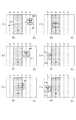
図3は本実施例のカメラCの焦点検出領域(以下、AF枠と呼ぶことがある)を示したものである。本実施例では、撮像範囲300内に水平3枠×垂直3枠の計9つのAF枠301を設定しており、9枠同時にデフォーカス量を取得可能となっている。便宜上、9つのAF枠301を図示のようにそれぞれ、Window1〜Window9と称する。 FIG. 3 shows a focus detection area (hereinafter sometimes referred to as an AF frame) of the camera C of the present embodiment. In the present embodiment, a total of nine
次に図4((a)、および(b))は本実施例において人を撮像する際に設定される顔枠403とAF枠404を示したものである。図4には、撮像範囲(画角)400の中に、被写体として人の顔401(胴体部は不図示)と遠距離の背景(空白部分)、および柱402をとらえているシーンを示す。このシーンにおいて、被写体抽出回路111による顔検出結果によって顔枠403が設定される。さらに、設定された顔枠に基づいてAF枠404が設定される。顔枠403は検出した顔の外周を一つの枠としており、顔の大きさにもよるが、図4においては3×3に顔枠を9分割した枠をAF枠404として設定し、各9枠個別に測距、デフォーカス量を算出する。図示していないが、設定される顔枠403が小さくなれば、段階的に2×2の4枠でAF枠を構成したり、1×1の1枠でAF枠を構成し、測距する構成となっている。本実施例では、3×3の9枠でAF枠404を構成する場合を例にとり、以後の説明を行う。 Next, FIGS. 4A and 4B show a
図5(a)〜(f)には、人が移動しているときに顔枠403が顔401を追尾している様子を所定時間間隔でサンプリングした際の各フレームにおける画像500と顔枠403を示す。図5(a)に示した時刻t1では、追尾対象である顔401が画像500のx方向(紙面横方向)においてX1の位置にあり、顔検出により顔枠403が表示されている状態である。顔401は矢印で示した移動方向501で示される方向へ移動している。なお、この移動方向501はカメラへt近づく方向の移動でもあり、画角上の平面方向(X,Y方向)と、カメラの光軸方向(Z方向)へも等速で歩くまたは走る等の移動しているものとする。顔401は時刻t2でX2に(図5(b))、時刻t3でX3に(図5(c))、時刻t4でX4に(図5(d))移動している。時刻t3では顔401の一部が柱に隠れてしまっており、顔検出ができておらず、追尾対象を見失った(ロスト)状態となっている。時刻t4でも顔401は完全に柱402に隠れており、被写体抽出回路111は追尾対象を完全にロストした状態である。ただ、顔401が等速で移動しているとすると、顔401はX4の位置を中心に存在していることになる。FIGS. 5A to 5F show an
時刻t5では顔401はX5に位置しており(図5(e))、顔401の約半分が見えているが、この段階では被写体抽出回路111では顔と検出できない。時刻t6では顔401はX6に移動し、柱401から完全に顔401がでており(図5(f))、追尾対象の顔401を再び検出でき、顔枠403を再度設定できている。図5((a)〜(f))に示したこのようなシーンにおけるAF枠404の動きを、図6((a)〜(f))に示している。なお図5(a)〜図5(f)にそれぞれ図6(a)〜図6(f)が対応している。Timet 5 the
時刻t1で顔401がX1の位置で顔検出されているとき、AF枠404は3×3の9枠が設定されている(図6(a))。顔401は時刻t2でX2に移動しているが、顔検出されており、図6(a)と同様に9枠のAF枠404が設定されている(図6(b))。尚、ここでは被写体抽出回路111において検出された顔401が同一であるか特徴量から判断を行っている。検出された顔401が同一であると判断されると、得られた各フレームの画像を比較することで追尾対象である顔401の移動方向に関する情報である動きベクトルを取得し、この取得結果を用いてXY平面上での追尾対象の動きを追尾(トラッキング)を行う。また、各フレームのAF枠404による焦点状態の検出結果を比較することで、Z方向の動きもトラッキングを行う。When the
時刻t3では顔401はX3に移動している(図6(c))。時刻t3におけるAF枠404の設定は、直前のフレームを取得した時刻t2までに取得した顔401の移動方向に関する情報に基づいて時刻t3における顔401の位置の予測した結果に基づいて行われる。移動方向に関する情報は、追尾対象が移動する方向だけでなく、速度(移動量)の情報も含むことが好ましい。また、xy平面上における方向だけでなく、z軸方向における移動の情報も含まれることが好ましい。Face 401 at timet 3 is moved inX 3 (Figure 6 (c)). Setting
時刻t3では、顔401の一部が柱402に隠れてしまっていて、被写体抽出回路111は顔401を検出できていない。しかしながら、時刻t1、t2で得られた各フレームの画像から取得した移動方向に関する情報に基づいてAF枠404を設定することで、9枠のうち、Window3、6、9がおよそ追尾対象の被写体(顔401)の位置をとらえている。またそれ以外のWindowでは顔401よりも近距離にある柱402の位置をとらえており、柱402までの距離を測距することになる。時刻t4では顔401は完全に柱402に隠れており(図6(d))、さらに、前のフレーム(図6(c))ですでに顔検出できていない。また前のフレームの測距結果よって予測通りの測距結果(Window3、6、9)に加えて、Window1などで近距離側に被写体を捕捉できているので、このフレームでは、一旦ロストした顔401が再度現れる位置をサーチする動きを行う。具体的には、追尾対象(顔401)の移動方向501において、どこまで近距離被写体(柱402)が存在するのか、またどの位置で背景抜けして、追尾対象よりも遠距離側の測距結果が得られるか、をサーチする。それにより、顔401の移動方向501において、顔よりも近距離側に存在する被写体(柱402)と遠距離側に存在する被写体(背景)との境界の位置を取得し、この位置周辺に追尾対象が現れるものと予測してAF枠404を設定する。追尾対象が現れると予測される境界の位置を出現予測位置とし、出現予測位置を含む位置もしくは出現予測位置よりも移動方向側にAF枠404を設定するものとする。このような、被写体が再出現する位置を予測するために、追尾対象をロストした周辺から出現予測位置を捜索する動作を、周辺捜索動作とよぶ。周辺捜索動作においては、AF枠404の中心(Window5の中心)が、動きベクトルから予測した、t4における顔401の中心位置に配置されるようにAF枠が設定される。At time t3 , a part of the
これにより、時刻t4において、時刻t3でAF枠404の中心(Window5の中心)が位置した位置よりも移動方向501方向よりにAF枠404の中心が位置するようにAF枠404の位置が移動し、測距が行われる。本実施例では、近距離被写体である柱402が移動しないものとみなし、各フレーム間(ここではt3とt4)において、AF枠404同士の重複を大きくしない。t3ではWindow1、2、4、5、7、8が柱402を捉えており、t4においても柱402は同じ位置に存在すると考えられる。よって、Window3、6、9のそれぞれが、t3におけるWindow1、4、7のそれぞれと同じ位置もしくはそれぞれの位置よりも移動方向501側になるようにAF枠を設定する。これにより、フレーム間でAF枠404が、AF枠を分割した分割枠(各Window)の複数行及び複数列分重複しない。本実施例では、t4において、Window3、6、9のそれぞれが、t3におけるWindow1、4、7のそれぞれと同じ位置になるようにAF枠404を設定する。これにより、t4ではWindow1〜Window9のすべてで柱402を捉えており、柱までの距離を測距することになる。よって、時刻t3で検出された距離と同じような位置に近距離被写体が存在していることが検出できることになる。Thus, at time t4 , the position of the
続いて時刻t5(図6(e))でも、t4(図6(d))の時と同様にAF枠404を顔401の移動方向(時刻t2までに検出した移動方向から予測される、t4とt5の間の移動方向)に動かしている。これにより、時刻t5においてAF枠404は柱402(Window3など)、背景(Window1など)、および顔401(Window5など)を捕捉している。このように追尾対象の被写体が近距離被写体に一時的に隠れるような場面では、追尾対象の被写体の移動方向を予測し、予測される追尾対象の被写体よりも遠距離側に位置する遠距離被写体(背景を含む)、および近距離被写体の検出を行う(周辺捜索)。そして、追尾対象の被写体が現れる位置を予測してAF枠404を先行して配置する。これにより、図6(f)に示す時刻t6では、X6に追尾対象の被写体が来て、顔検出により顔401を検出できた瞬間にはAF枠404を構成する各分割枠(Window)においてAF用の測距結果を得ていることになる。そのため、すぐにフォーカス動作が可能となる。Subsequently, at the time t5 (FIG. 6E), the
上述したt1〜t6までの被写体追尾及び周辺捜索に伴うAF枠設定とAF枠内の測距結果を図7に示す。図7の上方のグラフは、時間と測距結果との関係を示すグラフであり、横軸を時間t、縦軸をAF枠内の測距結果(デフォーカス量を被写体距離換算したもの)としている。また、下方の表は、それぞれの時刻におけるAF枠設定方法を示す表である。その時刻におけるAF枠の位置の設定が、追尾対象の追尾結果又は追尾予測によるものである場合は、表の追尾予測の欄に四角を示す(t1、t2)。また、その時刻におけるAF枠の位置の設定が、追尾対象が再出現する位置の捜索を行うための周辺捜索を行うためのものである場合は、表の周辺捜索の欄に四角を示す(t3〜t5)。周辺捜索を行うためのAF枠の設定は、追尾対象をロストしている期間(図7上方に矢印で示す)内に取得されるフレームにおいて行われる。また、その時刻におけるAF枠の位置の設定が、周辺捜索により取得された再出現予測位置に基づくものである場合は、表の出現予測位置の欄に四角を示す(t6)。FIG. 7 shows the AF frame setting and the distance measurement result in the AF frame associated with the subject tracking and the peripheral search from t1 to t6 described above. The upper graph in FIG. 7 is a graph showing the relationship between time and the distance measurement result. The horizontal axis represents time t, and the vertical axis represents the distance measurement result in the AF frame (defocus amount converted to subject distance). Yes. The lower table is a table showing the AF frame setting method at each time. If the setting of the position of the AF frame at that time is based on the tracking result or tracking prediction of the tracking target, a square is shown in the tracking prediction column of the table (t1 , t2 ). In addition, when the setting of the position of the AF frame at that time is for performing a peripheral search for searching for a position where the tracking target reappears, a square is shown in the peripheral search column of the table (t3 ~t5). The setting of the AF frame for performing the peripheral search is performed in a frame acquired within a period during which the tracking target is lost (indicated by an arrow in the upper part of FIG. 7). In addition, when the setting of the position of the AF frame at that time is based on the re-appearance predicted position acquired by the peripheral search, a square is shown in the column of the predicted appearance position in the table (t6 ).
t1〜t2の間は、分割枠9枠がほぼ追尾対象をとらえており、実際に取得したフレームの画像を用いて追尾対象の検出を行い、追尾対象が検出された位置にAF枠を設定しており、約5mから近付いている追尾対象の動作を捕捉している。時刻t3では追尾対象の移動方向情報に基づいて、周辺捜索を行うためのAF枠を設定している。設定されたAF枠内の測距によって、追尾対象の予測位置に近い距離(約4.5m)と、追尾対象の予測位置より手前(約2m)に障害物であろう近距離被写体が存在する結果が得られている。Between t1 and t2 , the divided frame 9 almost captures the tracking target, detects the tracking target using the actually acquired frame image, and sets the AF frame at the position where the tracking target is detected. It is set and the movement of the tracking target approaching from about 5 m is captured. At time t3 based on the movement direction information of the tracking target, and sets the AF frame for performing a neighboring search. By the distance measurement within the set AF frame, there is a distance close to the predicted position of the tracking target (about 4.5 m) and a near-distance subject that may be an obstacle before the predicted position of the tracking target (about 2 m). The result is obtained.
時刻t4、t5でも、追尾対象の移動方向の情報に基づいて、周辺捜索を行うためのAF枠を設定している。時刻t4では、設定されたAF枠内の測距によって、近距離側の測距結果(近距離被写体に基づく測距結果)のみが得られている。時刻t5では、AF枠の大部分は近距離被写体を抜けており、AF枠内の測距によって、再出現予測位置よりも十分に遠距離側(背景)の測距結果(無限遠)と、追尾対象の予測距離に近い結果(約4m)が得られる。このように、AF枠内に近距離被写体(柱402)と遠距離被写体(背景)の両方がそれぞれ出現したことにより、追尾対象が再出現するであろう再出現予測位置が取得できる。これにより出現予測位置にAF枠404を設定することを時刻t5とt6の間に決定することで、時刻t6ではAF枠404を出現予測位置に配しておくことができる。よって、時刻t6でフレームを取得すると、追尾対象の検出とAF枠内の測距を同時並行で行うこともできる。また、移動結果として追尾対象の光軸方向を含む移動結果に関する情報を取得しておくと、追尾対象を見失う前までの移動結果に基づく情報から追尾対象までの距離を予測することが可能である。よって、AF枠の設定と追尾対象の予測位置へのピント調節を同時に行うことができる。こうすることによって、予測位置が正確であれば、追尾対象を再度検出するよりも先に追尾対象に対してピントを合わせることができる。つまり、追尾対象が柱402から半分だけ出ているような状況であっても、被写体追尾AFにより追尾対象にピントを合わせることができるため、追尾対象の被写体が復帰した際、より高速に追尾対象の被写体に対してピントを合わせることができると考えられる。At times t4 and t5 , an AF frame for performing a peripheral search is set based on information on the movement direction of the tracking target. At time t4, the distance measurement in the AF frame that has been set, only the near side of the measurement result (measurement result based on the close range object) is obtained. At time t5, the majority of the AF frame is missing a near object, the distance measurement in the AF frame, the measurement result of the re-appearance estimated sufficiently far side of a position (background) and (infinity) A result (about 4 m) close to the predicted distance of the tracking target is obtained. As described above, when both the short-distance subject (column 402) and the long-distance subject (background) appear in the AF frame, the re-appearance predicted position where the tracking target will reappear can be acquired. By thus determining between times t5 and t6 to set the
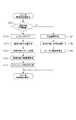
次に、カメラCによる被写体追尾の動作を図8から図12までのフローチャートを用いて説明する。尚、フローチャートにおいて符号の頭につくSはステップを示す。 Next, the subject tracking operation by the camera C will be described with reference to the flowcharts of FIGS. In the flowchart, S at the beginning of the code indicates a step.
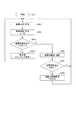
図8は本実施例における被写体追尾のAF処理を示すフローチャートである。S801でAF動作を開始した後、S802において撮像素子101からの画像を取り込み、焦点検出用の画像生成および生成した画像の記憶を行う。次のS803では焦点検出用の画像を用いて像面の位相差測距による焦点検出を9枠分個別に行い、検出結果を記憶する。Window1〜9の測距結果をそれぞれf1〜f9としている。測距結果として像面のデフォーカス量を用い、デフォーカス量を記憶してもよいが、本実施例ではデフォーカス量を被写体距離に換算したものを測距結果として用いるものとして説明を行う。S804では現在、追尾対象の被写体が特定されているかを判定するために、追尾対象特定中フラグがONか否かを判定し、フラグがONの場合には、S805へ進み、フラグがONでない場合には、S806へ進む。S806では、被写体の検出・または抽出処理を行い、S807では、追尾対象を特定したか否かを判定する。S807で人の顔など特定の被写体が追尾対象とされていると判定された場合には、S808に進み、追尾状態であることを保持するフラグとして追尾対象特定中フラグをONとしてS802に戻り、次のフレームの処理を行う。また追尾対象の被写体が特定できなければ、このフラグをONとしないままS802に戻り、次のフレーム処理を行う。 FIG. 8 is a flowchart showing subject tracking AF processing in this embodiment. After the AF operation is started in S801, an image from the
一方で、S804において、追尾対象特定中フラグがONである場合は、S805へ進み、被写体トラッキング処理を行う。この被写体トラッキング処理のフローチャートを図9に示す。 On the other hand, if the tracking target identifying flag is ON in S804, the process proceeds to S805 to perform subject tracking processing. FIG. 9 shows a flowchart of the subject tracking process.
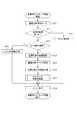
被写体トラッキング処理が開始されると、S901では追尾対象の被写体が画像中に存在するかサーチを行う。S902では、S901でのサーチ結果に基づいて、追尾対象と思われる被写体が見つかった否かを判定する。追尾対象と思われる被写体が見つかった場合はS903へ進み、追尾対象と思われる被写体が見つからなかった場合(ロストした場合)はS909へ進み、ロスト時処理を行う。S903では、追尾対象をロストした後に復帰した場合であるかを判定する。一旦追尾対象の被写体をロストした後に再度追尾対象が見つかったロスト後の復帰である場合には、S910へ進み、ロスト後復帰処理が行われる。ロストしたわけでなく、直前のフレームでも追尾対象を検出している場合には、S904へ進み、撮像範囲(画角)における追尾対象の位置を記憶し、次のS905では追尾対象のサイズを記憶する。次にS906において、前回のフレームでの追尾対象の位置と今回のフレームでの追尾対象の位置とを比較することで、xy平面での移動量を取得し、次のS907ではS906で取得した移動量を用いてトラッキング枠設定処理を行う。尚、被写体トラッキング処理のフローを図6に当てはめると、t2はS901〜908を進み、t3〜t5はS902でS909へ進み、t6はS903でS901へ進む。When the subject tracking process is started, a search is performed in S901 as to whether or not the subject to be tracked exists in the image. In step S902, based on the search result in step S901, it is determined whether a subject that is considered to be a tracking target has been found. If a subject considered to be a tracking target is found, the process proceeds to step S903. If a subject considered to be a tracking target is not found (if lost), the process proceeds to step S909, and a lost time process is performed. In step S <b> 903, it is determined whether the tracking target has returned after being lost. If the tracking target is once lost and then the tracking target is found again, and the return is after lost, the process proceeds to S910, and the recovery processing after lost is performed. If the tracking target has not been lost and the tracking target has been detected in the immediately preceding frame, the process proceeds to S904, where the tracking target position in the imaging range (angle of view) is stored, and in the next S905, the tracking target size is stored. To do. Next, in S906, the amount of movement on the xy plane is acquired by comparing the position of the tracking target in the previous frame with the position of the tracking target in the current frame. In the next S907, the movement acquired in S906 is acquired. The tracking frame setting process is performed using the amount. Incidentally, when applying a flow of the subject tracking process in FIG. 6,t 2 advances theS901~908,
S907のトラッキング枠設定処理の詳細について図11を用いて説明を行う。
図11は、トラッキング枠設定処理のフローチャートである。トラッキング枠設定処理が開始されると、まずS1101において次のフレームまでの移動量を予測する予測処理を行う。この移動量は、xy平面における移動量であり、S906で取得した移動量をもとに取得する。次のS1102では、S803において保持されている被写体の距離(f1〜f9)の履歴を用いて、カメラの光軸方向(z方向)における移動量を予測し、追尾対象がカメラに近づいているかを判定する。追尾対象がカメラに近づいている場合には、S1107へ進み、次のフレームでの追尾対象の大きさを推定計算して、AF枠のサイズ(面積)を大きくする。追尾対象がカメラに近づいていない場合には、S1103に進み、追尾対象がカメラから遠ざかっているかを判定する。追尾対象がカメラに遠ざかっている場合にはS1108に進み、AF枠サイズを小さくするように設定する。追尾対象とカメラとの距離が変わらない場合にはAF枠サイズも変わらないようにする。次のS1104においては、S1104までに決定したAF枠サイズの大きさから、枠数の最適化がおこなわれる。本実施例では、AFの分割枠サイズに上限と下限を設けて、例えば特定されている追尾対象の大きさによってAF枠の分割数を決定する。例えば水平方向において、分割枠のサイズは40pixから80pixと設定し、AF枠サイズが108pixの場合、このAF枠を54pixの2枠に分割する。同様に垂直方向も分割枠サイズの最適化を行う。次のS1105において、S1104までに設定した分割枠数、AF枠サイズを次のフレーム(次回)のAF枠の分割数、AF枠サイズとする設定を行う。加えて、S904及びS906に基づいて次フレームの追尾対象の位置を予測し、予測位置に次回のAF枠の位置を設定する。次のS1106では、今回フレームでのAF枠の分割枠それぞれの測距結果(f1〜f9)のうち、前回フレームでの予測結果に最も近い結果を得られているデフォーカス検出結果を用いてフォーカス駆動量の設定を行う。以上がトラッキング枠設定処理となる。Details of the tracking frame setting process in S907 will be described with reference to FIG.
FIG. 11 is a flowchart of the tracking frame setting process. When the tracking frame setting process is started, first, a prediction process for predicting a movement amount to the next frame is performed in S1101. This movement amount is a movement amount in the xy plane, and is acquired based on the movement amount acquired in S906. In the next S1102, the movement distance in the optical axis direction (z direction) of the camera is predicted using the history of the subject distances (f1 to f9) held in S803, and it is determined whether the tracking target is approaching the camera. judge. If the tracking target is approaching the camera, the process advances to step S1107 to estimate the size of the tracking target in the next frame and increase the size (area) of the AF frame. If the tracking target is not approaching the camera, the process advances to step S1103 to determine whether the tracking target is moving away from the camera. If the tracking target is away from the camera, the process advances to step S1108 to set the AF frame size to be small. When the distance between the tracking target and the camera does not change, the AF frame size is also prevented from changing. In the next S1104, the number of frames is optimized based on the size of the AF frame size determined up to S1104. In the present embodiment, an upper limit and a lower limit are provided for the AF division frame size, and the number of AF frame divisions is determined based on, for example, the size of the tracking target that is specified. For example, in the horizontal direction, the size of the divided frame is set from 40 pix to 80 pix, and when the AF frame size is 108 pix, the AF frame is divided into two frames of 54 pix. Similarly, the size of the divided frame is also optimized in the vertical direction. In the next S1105, the number of divided frames and the AF frame size set up to S1104 are set as the number of divided AF frames and the AF frame size of the next frame (next time). In addition, the tracking target position of the next frame is predicted based on S904 and S906, and the position of the next AF frame is set as the predicted position. In the next S1106, focusing is performed by using the defocus detection result that has obtained the result closest to the prediction result in the previous frame among the distance measurement results (f1 to f9) of the divided frames of the AF frame in the current frame. Set the drive amount. The above is the tracking frame setting process.
トラッキング枠設定処理が終了すると、図9に戻って、S908に進む。S908では、S907のS1106で設定したフォーカス駆動量に基づいて、AF動作を行う。このとき、同時にAE動作を行ってもよい。複数のフレームにまたがって追尾対象の被写体を検出してトラッキングしている期間は、これまでに説明した動作を繰り返すことになる。 When the tracking frame setting process ends, the process returns to FIG. 9 and proceeds to S908. In S908, an AF operation is performed based on the focus drive amount set in S1106 of S907. At this time, the AE operation may be performed simultaneously. The operation described so far is repeated during a period in which the tracking target object is detected and tracked across a plurality of frames.
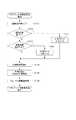
ここでS902において追尾対象の被写体を見失った場合、S909へ移行して、ロスト時処理が行われる。このロスト時処理を図10を用いて説明する。ロスト時処理が始まると、まずS1001において前のフレームまでは追尾対象の被写体が検出できており、このフレームがロスト直後であるかどうかの判定が行われる。ロスト直後の場合、S1002に進んでロスト位置(前のフレームにおける追尾対象の位置)のx、y、z方向における位置をf_lostとして記憶し、ロスト状態であることを保持するロストフラグをONとして、S1003へ進む。 If the subject to be tracked is lost in S902, the process proceeds to S909 and the lost time process is performed. This lost process will be described with reference to FIG. When the lost process starts, first, in S1001, the subject to be tracked can be detected up to the previous frame, and it is determined whether or not this frame is immediately after the lost frame. In the case of immediately after the lost, the process proceeds to S1002, the position in the x, y, z direction of the lost position (tracking target position in the previous frame) is stored as f_lost, and the lost flag that holds that the lost state is set to ON, The process proceeds to S1003.
S1003では、今回のフレームのAF枠の各分割枠の測距結果から、ロストした位置(距離)よりも近距離側に被写体が存在するかどうかを判定する。AF枠内に近距離被写体が存在しない場合、S1006に進み、次のフレームにおけるAF枠(次回枠と呼ぶことがある)の位置を変更しないものとし、次のステップS1005で、フォーカス駆動も行わないように駆動量をゼロに設定する。 In S1003, it is determined from the distance measurement result of each divided frame of the AF frame of the current frame whether or not the subject is present on the nearer side than the lost position (distance). If there is no short-distance subject within the AF frame, the process proceeds to S1006, where the position of the AF frame (sometimes referred to as the next frame) in the next frame is not changed, and focus driving is not performed in the next step S1005. Set the drive amount to zero.
またS1003においてAF枠内に近距離被写体が存在していると判定された場合、S1004では次回枠を設定する。本実施例では、S1004における次回枠の設定は、今回のフレームの測距により、近距離被写体が存在すると判定された分割枠(Window)の移動方向側の端が、次回フレームのAF枠内に含まれるように次回フレームのAF枠位置を設定することで行う。言い換えると、t3において近距離被写体が存在すると判定された分割枠Window1、4、7の左端が、t4においてAF枠内に含まれるようにt4におけるAF枠を設定する。このとき、分割枠の移動方向の端は、次回フレームのAF枠のうち、移動方向と反対側の端に位置する分割枠(Window3、6、9)に含まれることが好ましく、次回フレームのAF枠のうち移動方向と反対側の端と重なることがさらに好ましい。そのうえで次のステップS1005で、フォーカス駆動を行わないように駆動量をゼロに設定する。 If it is determined in S1003 that a short-distance subject exists within the AF frame, the next frame is set in S1004. In the present embodiment, the next frame setting in S1004 is performed by setting the end in the moving direction of the divided frame (Window) determined that the near-distance subject exists by the distance measurement of the current frame within the AF frame of the next frame. This is done by setting the AF frame position of the next frame so that it is included. In other words, the AF frame at t4 is set so that the left ends of the divided frames Windows1, 4, and 7 determined to have a short-distance subject at t3 are included in the AF frame at t4. At this time, the end of the divided frame in the moving direction is preferably included in the divided frame (
また、S1001において、ロスト直後でないつまり今回のフレームがロスト後の2フレーム目以降のフレームであると判定された場合には、S1007へ進み、まずロスト回数をカウントする。ロストカウントが所定以上の場合には、完全にロストしたことによる初期化を行うためのタイムアウト機能を実行するためである。次のステップS1008において追尾対象の移動予測方向に、ロストした追尾対象よりも近距離側に被写体があるかどうかの判定を行う。近距離被写体がある場合には、S1009へ進み、さらに追尾対象の移動予測方向にロストした追尾対象よりも遠距離側に被写体があるかどうかを判定する。S1008、S1009ともにロスト直前の距離(f_lostのz方向の位置)と毎フレームごとに設定した各AF枠から得られた測距結果をもとに判断を行う。追尾対象のロスト位置よりも近距離側、および遠距離側に被写体の存在が検出できるとS1010に進み、遠距離側の被写体と近距離側の被写体の間に(境界を含むように)次回フレームのAF枠を設定し、S1005に進む。この次回枠の設定は、上述した出現予測位置におけるAF枠の設定であり、t5のフレームを取得した際のt6のフレーム(次回フレーム)のAF枠の設定である。 If it is determined in S1001 that the frame is not immediately after the loss, that is, the current frame is the second or subsequent frame after the loss, the process proceeds to S1007, and the number of lost times is first counted. This is because when the lost count is greater than or equal to a predetermined value, a time-out function for performing initialization due to complete loss is executed. In the next step S1008, it is determined whether or not there is an object closer to the tracking target movement direction than the lost tracking target. If there is a near-distance subject, the process proceeds to S1009, and it is further determined whether or not there is a subject on the far side of the tracking target lost in the movement prediction direction of the tracking target. In both S1008 and S1009, a determination is made based on the distance immediately before the loss (position of f_lost in the z direction) and the distance measurement result obtained from each AF frame set for each frame. If it is possible to detect the presence of the subject on the near side and the far side of the tracking target lost position, the process proceeds to S1010, and the next frame (including the boundary) between the far side subject and the near side subject. AF frame is set, and the process proceeds to S1005. The setting of the next frame is the setting of the AF frame at the appearance prediction position described above, and is the setting of the AF frame of the frame at t6 (next frame) when the frame at t5 is acquired.
追尾対象のロスト位置よりも遠距離側、又は近距離側のどちらか一方でもAF枠検出結果から被写体の存在を検出できない場合には、S1011へ移行して、ロスト回数が所定以上かを判定する。ロスト回数が所定の回数以上である場合(例えば20回以上連続して被写体が見つからない場合)、S1013に進み、タイムアウト処理として、被写体トラッキング状態を保持する、追尾対象特定中フラグをOFFにし、トラッキングを終了する。その後次のステップS1014においてAF枠をデフォルトの位置に設定する。本実施例では、デフォルトの位置として画角中央に次回枠設定を行う。またステップS1011においてロスト回数が所定回数より少ないと判定された場合、S1012において次回フレームにおけるAF枠の設定を行う。この次回枠の設定は、上述した周辺捜索によるAF枠の設定であり、t3、t4フレームを取得した際の次回フレームのAF枠の設定である。S1012による次回枠の設定は、移動予測設定であり、追尾対象がロスト前の追尾対象の移動方向へ動いているものとして、次回フレームのAF枠を前フレームのAF枠よりも移動方向へ移動させた位置として設定するものである。このような次回枠の移動により、次のフレームでも再度追尾対象をロスト中であれば、被写体の移動方向に追尾対象のロスト位置よりも近距離側、遠距離側の両方に被写体が見つかるまで、AF枠サーチするような動作となる。S1006、S1004、S1010、S1012、S1014において次回枠が設定されると、S1005へ進む。S1005ではフォーカス駆動量をゼロに設定する。つまり、ロスト時はフォーカスレンズの駆動は行わない。ロスト時処理が終了すると、図9の被写体トラッキング処理のフローに戻り、S908へ進む。S1005でフォーカス駆動量をゼロに設定しているため、S909からS908に進む場合はS908にてフォーカス駆動は行われず、被写体トラッキング処理として次のAF検出枠設定が行われてS802に戻り、次回フレームの処理が行われる。 If the presence of the subject cannot be detected from the AF frame detection result on either the far side or the near side of the tracking target lost position, the process proceeds to S1011 to determine whether the number of lost times is equal to or greater than a predetermined value. . When the number of lost times is equal to or greater than a predetermined number (for example, when no subject is continuously found 20 times or more), the process proceeds to S1013, and the tracking target identification flag that holds the subject tracking state is turned off as a time-out process. Exit. Thereafter, in the next step S1014, the AF frame is set to a default position. In this embodiment, the next frame is set at the center of the angle of view as the default position. If it is determined in step S1011 that the number of lost times is less than the predetermined number, in step S1012, an AF frame is set in the next frame. The setting of the next frame is the setting of the AF frame by the peripheral search described above, and is the setting of the AF frame of the next frame when the t3 and t4 frames are acquired. The setting of the next frame in S1012 is a movement prediction setting, and the AF frame of the next frame is moved in the movement direction more than the AF frame of the previous frame, assuming that the tracking target is moving in the movement direction of the tracking target before the lost. This is set as the position. If the tracking target is lost again in the next frame due to the movement of the next frame, until the subject is found on both the near side and the far side of the tracking target in the moving direction of the subject, The operation is similar to AF frame search. When the next frame is set in S1006, S1004, S1010, S1012, and S1014, the process proceeds to S1005. In step S1005, the focus drive amount is set to zero. That is, the focus lens is not driven during the lost time. When the lost process is completed, the process returns to the subject tracking process flow of FIG. 9 and proceeds to S908. Since the focus drive amount is set to zero in S1005, when the process proceeds from S909 to S908, focus drive is not performed in S908, the next AF detection frame setting is performed as subject tracking processing, and the process returns to S802 to return to the next frame. Is performed.
被写体トラッキング処理のS903において、ロスト後の復帰であると判定された場合、S910へ進み、ロスト後の再復帰処理が行われる。ロスト後の再復帰処理について図12を用いて説明をする。図12は、ロスト後の再復帰処理のフローチャートである。ロスト後の再復帰処理が始まると、最初のステップS1201では今回フレームでのAF検出結果および追尾対象のxy平面での位置がロスト位置及びロスト時からの時間に基づいて予測される、予測範囲内であるかどうかを判定する。復帰した追尾対象が、予測範囲内に存在する場合は、S1202においてロスト状態であることを保持するロストフラグをOFFとしてS1203に進み、再度トラッキング状態に入る。S1203〜S1206は、図9のS904〜907と同じステップであるため、説明を省略する。 If it is determined in S903 of the subject tracking process that the return is after the lost process, the process proceeds to S910, and the return process after the lost process is performed. The re-restoration process after the lost will be described with reference to FIG. FIG. 12 is a flowchart of re-restoration processing after lost. When the re-restoration process after lost starts, in the first step S1201, the AF detection result in the current frame and the position of the tracking target on the xy plane are predicted based on the lost position and the time from the lost time. It is determined whether or not. If the returned tracking target exists within the prediction range, the lost flag that holds that it is in the lost state is turned off in S1202, the process proceeds to S1203, and the tracking state is entered again. Since S1203 to S1206 are the same steps as S904 to 907 in FIG.
一方で、ステップS1201において復帰した追尾対象が予測範囲外に位置する場合には、ステップS1207へ進み、移動量の再予測処理を行う。この処理は、予測処理のリセットとなり、今回のフレームでは正しい予測結果がえられないので追尾対象を最初に検出した時と同様の処理(S807、S808と同様の処理)となる。よって次のステップS1208では追尾対象の検出位置に次回枠を設定し、S1209では今回フレームでの測距結果に基づいてフォーカス駆動量を設定し、ロスト後再復帰処理の終了となる。 On the other hand, if the tracking target returned in step S1201 is located outside the prediction range, the process proceeds to step S1207, and the movement amount re-prediction processing is performed. This process is a reset of the prediction process, and since a correct prediction result cannot be obtained in the current frame, the process is the same as when the tracking target is first detected (the process similar to S807 and S808). Therefore, in the next step S1208, the next frame is set at the tracking target detection position, and in S1209, the focus drive amount is set based on the distance measurement result in the current frame, and the post-lost re-restoration process is completed.
(変形例)
上述の実施例では、焦点検出装置を備える撮像装置であるレンズ一体型のカメラに本発明を適用した場合の一実施例について説明をした。しかしながら、本発明にかかる焦点検出装置は撮像センサの画像信号を用いて焦点検出を行う任意の電子機器に適用可能である。電子機器としては、レンズ交換式のデジタルカメラや、ビデオカメラの他、カメラを備えた携帯電話機、パーソナルコンピュータ、ゲーム機、家電機器などが例として挙げられる。(Modification)
In the above-described embodiment, an embodiment in which the present invention is applied to a lens-integrated camera that is an imaging device including a focus detection device has been described. However, the focus detection apparatus according to the present invention can be applied to any electronic device that performs focus detection using an image signal of an imaging sensor. Examples of electronic devices include interchangeable lens digital cameras and video cameras, as well as mobile phones equipped with cameras, personal computers, game machines, and home appliances.
また、上述の実施例では、追尾対象が検出されている間も追尾予測を行い、追尾予測に基づいて次回枠の設定を行ったが、追尾対象が検出されている間は追尾予測を行わず、追尾対象の検出結果に基づいてAF枠を設定してもよい。予測ではなく実測で追尾対象に対してAF枠を設定するため、より正確に追尾対象に対してAF枠を設定することができる。一方、フレームの取得、及び追尾対象の検出を行ってからAF枠を設定するため、追尾予測でAF枠を設定するよりもAF枠の設定まで時間が必要である。 Further, in the above-described embodiment, the tracking prediction is performed while the tracking target is detected, and the next frame is set based on the tracking prediction. However, the tracking prediction is not performed while the tracking target is detected. The AF frame may be set based on the detection result of the tracking target. Since the AF frame is set for the tracking target by actual measurement rather than prediction, the AF frame can be set for the tracking target more accurately. On the other hand, since the AF frame is set after obtaining the frame and detecting the tracking target, it takes more time to set the AF frame than setting the AF frame in tracking prediction.
また、上述の実施例では、被写体までの距離を用いて近距離被写体と遠距離被写体の有無を判定したが、デフォーカス量を用いて近距離被写体と遠距離被写体をの有無を判定してもよい。また、図10に示したロスト時処理のフローにおいて、S1006では次のフレームにおけるAF枠の位置を変更しないものとしたが、AF枠の位置を変更してもよい。例えば、近距離被写体がないため、追尾対象がフレームアウトしたとみなし、AF枠を画角の境界を含む境界部に配してもよいし、撮影者が撮像装置の画角を移動させることを期待して画角の中央に移動してもよい。 In the above-described embodiment, the presence / absence of a short-distance subject and a long-distance subject is determined using the distance to the subject. However, the presence / absence of a short-distance subject and a long-distance subject can be determined using the defocus amount. Good. Further, in the lost time processing flow shown in FIG. 10, the position of the AF frame in the next frame is not changed in S1006, but the position of the AF frame may be changed. For example, since there is no near-distance subject, it is considered that the tracking target is out of frame, and the AF frame may be arranged at the boundary including the boundary of the angle of view, or the photographer may move the angle of view of the imaging device. You may move to the center of the angle of view in anticipation.
また、上述の実施例では、被写体抽出等を回路により実行したが、ソフトウェアで実行してもよい。上述の実施例の1以上の機能を実現するプログラムを、ネットワーク又は記憶媒体を介してシステム又は装置に供給し、そのシステム又は装置のコンピュータにおける1つ以上のプロセッサーがプログラムを読出し実行する処理でも実現可能である。また、1以上の機能を実現する部(例えば、ASIC)によっても実現可能である。
以上説明した各実施例は代表的な例にすぎず、本発明の実施に際しては、各実施例に対して種々の変形や変更が可能である。In the above-described embodiment, the subject extraction and the like are executed by the circuit, but may be executed by software. A program that realizes one or more functions of the above-described embodiments is supplied to a system or apparatus via a network or a storage medium, and is also realized by a process in which one or more processors in a computer of the system or apparatus read and execute the program Is possible. It can also be realized by a unit (for example, ASIC) that realizes one or more functions.
Each embodiment described above is only a representative example, and various modifications and changes can be made to each embodiment in carrying out the present invention.
100 レンズユニット
101 撮像素子
102 分割像取得回路
103 位相差検出用アクセラレータ回路
104 撮像信号処理回路
105 画像処理回路
106 記録回路
107 画像メモリ
108 メモリ
109 CPU
110 レンズ駆動回路
111 被写体抽出回路DESCRIPTION OF
110
Claims (8)
Translated fromJapanese前記画像信号に基づいて、前記検出された追尾対象の被写体に対してのデフォーカス量に対応する情報を含む、前記検出された追尾対象の被写体の位置情報を取得する位置情報取得手段と、
前記取得した位置情報を用いて前記追尾対象の被写体の光軸方向を含む移動結果に関する情報を取得する移動結果取得手段と、
前記追尾対象の被写体の少なくとも一部が含まれるように前記焦点検出領域を設定する設定手段と、
前記設定された焦点検出領域に対応する画像信号に基づいて前記フォーカスレンズの位置を調整する焦点調節手段と、を備え、
前記検出手段が前記追尾対象の被写体を検出できないときは、
前記移動結果取得手段が取得した移動結果に基づいた位置に、前記設定手段が前記焦点検出領域を設定するとともに前記焦点調節手段が前記フォーカスレンズの位置を調整することを特徴とする焦点検出装置。Detecting means for detecting a subject to be tracked located in a focus detection region based on an image signal output from an image sensor that images a subject image formed by an imaging optical system including a focus lens;
Position information acquisition means for acquiring position information of the detected subject to be tracked including information corresponding to a defocus amount with respect to the detected subject to be tracked based on the image signal;
Movement result acquisition means for acquiring information related to a movement result including the optical axis direction of the subject to be tracked using the acquired position information;
Setting means for setting the focus detection area so as to include at least a part of the subject to be tracked;
Focus adjusting means for adjusting the position of the focus lens based on an image signal corresponding to the set focus detection area;
When the detection means cannot detect the subject to be tracked,
The focus detection apparatus, wherein the setting unit sets the focus detection area at a position based on the movement result acquired by the movement result acquisition unit, and the focus adjustment unit adjusts the position of the focus lens.
前記検出手段が前記追尾対象の被写体を検出できないときは、前記追尾対象の被写体よりも近くに位置する被写体の前記焦点検出領域内での有無を判定し、
前記位置情報取得手段により前記焦点検出領域内に前記追尾対象の被写体よりも近くに位置する被写体があると判定されたとき、
前記移動結果取得手段が取得した移動結果に基づいた位置に、前記設定手段が前記焦点検出領域を設定するとともに前記焦点調節手段が前記フォーカスレンズの位置を調整することを特徴とする請求項1に記載の焦点検出装置。The position information acquisition means includes
When the detection means cannot detect the subject to be tracked, determine whether or not a subject located nearer the subject to be tracked is within the focus detection area,
When it is determined by the position information acquisition means that there is a subject located closer to the tracking target subject in the focus detection area,
The focus setting unit adjusts the position of the focus lens while the setting unit sets the focus detection area at a position based on the movement result acquired by the movement result acquisition unit. The focus detection apparatus described.
前記移動結果取得手段が取得した移動結果に基づいて前記追尾対象の被検体が現れる位置を予測し、予測した位置を含むように前記焦点検出領域を設定することを特徴とする請求項1又は2に記載の焦点検出装置。The setting means includes
The position of the tracking target subject is predicted based on the movement result acquired by the movement result acquisition unit, and the focus detection area is set to include the predicted position. The focus detection apparatus described in 1.
前記検出手段が前記追尾対象の被写体を検出できないときは、前記追尾対象の被写体よりも近くに位置する被写体の前記焦点検出領域内での有無を判定し、
前記設定手段は、
前記位置情報取得手段により前記焦点検出領域内に前記追尾対象の被写体よりも近くに位置する被写体がないと判定されたとき、前記焦点検出領域の位置を変更しないことを特徴とする請求項1乃至3のいずれか1項に記載の焦点検出装置。The position information acquisition means includes
When the detection means cannot detect the subject to be tracked, determine whether or not a subject located nearer the subject to be tracked is within the focus detection area,
The setting means includes
The position of the focus detection area is not changed when it is determined by the position information acquisition means that there is no subject located in the focus detection area closer to the subject to be tracked. 4. The focus detection apparatus according to any one of items 3.
前記検出手段が前記追尾対象の被写体を検出できないときは、前記追尾対象の被写体よりも近くに位置する被写体の前記焦点検出領域内での有無を判定し、
前記設定手段は、
前記位置情報取得手段により前記焦点検出領域内に前記追尾対象の被写体よりも近くに位置する被写体がないと判定されたとき、撮像範囲の中央または撮像範囲の境界部の少なくともいずれかを含むように前記焦点検出領域を設定することを特徴とする請求項1乃至4のいずれか1項に記載の焦点検出装置。The position information acquisition means includes
When the detection means cannot detect the subject to be tracked, determine whether or not a subject located nearer the subject to be tracked is within the focus detection area,
The setting means includes
When it is determined by the position information acquisition means that there is no subject located closer to the tracking target subject in the focus detection area, at least one of the center of the imaging range or the boundary of the imaging range is included. The focus detection apparatus according to claim 1, wherein the focus detection area is set.
前記検出手段が前記追尾対象の被写体を検出できないときは、前記追尾対象の被写体よりも近くに位置する被写体の前記焦点検出領域内での有無を判定し、
前記設定手段は、
前記位置情報取得手段により前記焦点検出領域内に前記追尾対象の被写体よりも近くに位置する被写体があると判定されたとき、前記移動結果取得手段が取得した移動結果と前記画像信号を取得した時の前記焦点検出領域とに基づいて、
前記画像信号を取得した時の前記焦点検出領域よりも前記前記追尾対象の被写体の移動方向側に位置し、かつ、前記画像信号を取得した時の前記焦点検出領域の一部と重なるように前記焦点検出領域を設定することを特徴とする請求項1乃至5のいずれか1項に記載の焦点検出装置。The position information acquisition means includes
When the detection means cannot detect the subject to be tracked, determine whether or not a subject located nearer the subject to be tracked is within the focus detection area,
The setting means includes
When the movement information obtained by the movement result obtaining unit and the image signal are obtained when it is determined by the position information obtaining unit that there is a subject located closer to the tracking target subject in the focus detection area. Based on the focus detection area of
The focus detection area is located on the moving direction side of the subject to be tracked with respect to the focus detection area when the image signal is acquired, and overlaps with a part of the focus detection area when the image signal is acquired. The focus detection apparatus according to claim 1, wherein a focus detection area is set.
前記検出手段が前記追尾対象の被写体を検出できないときは、前記追尾対象の被写体よりも近くに位置する被写体の前記焦点検出領域内での有無及び前記追尾対象の被写体よりも遠くに位置する被写体の前記焦点検出領域内での有無を判定し、
前記設定手段は、
前記位置情報取得手段により前記焦点検出領域内に前記追尾対象の被写体よりも近くに位置する被写体及び前記追尾対象の被写体よりも遠くに位置する被写体があると判定されたとき、前記追尾対象の被写体よりも遠くに位置する被写体が含まれるように前記焦点検出領域を設定することを特徴とする請求項1乃至6のいずれか1項に記載の焦点検出装置。The position information acquisition means includes
When the detection means cannot detect the subject to be tracked, the presence / absence of the subject located near the subject to be tracked in the focus detection area and the subject located far from the subject to be tracked Determining the presence or absence within the focus detection area;
The setting means includes
When it is determined by the position information acquisition means that there is a subject located closer to the tracking target subject and a subject located farther than the tracking target subject in the focus detection area, the tracking target subject The focus detection apparatus according to claim 1, wherein the focus detection region is set so as to include a subject located farther away.
Priority Applications (1)
| Application Number | Priority Date | Filing Date | Title |
|---|---|---|---|
| JP2016130920AJP6818449B2 (en) | 2016-06-30 | 2016-06-30 | Focus detector |
Applications Claiming Priority (1)
| Application Number | Priority Date | Filing Date | Title |
|---|---|---|---|
| JP2016130920AJP6818449B2 (en) | 2016-06-30 | 2016-06-30 | Focus detector |
Publications (2)
| Publication Number | Publication Date |
|---|---|
| JP2018004916Atrue JP2018004916A (en) | 2018-01-11 |
| JP6818449B2 JP6818449B2 (en) | 2021-01-20 |
Family
ID=60944964
Family Applications (1)
| Application Number | Title | Priority Date | Filing Date |
|---|---|---|---|
| JP2016130920AExpired - Fee RelatedJP6818449B2 (en) | 2016-06-30 | 2016-06-30 | Focus detector |
Country Status (1)
| Country | Link |
|---|---|
| JP (1) | JP6818449B2 (en) |
Cited By (3)
| Publication number | Priority date | Publication date | Assignee | Title |
|---|---|---|---|---|
| JPWO2022153815A1 (en)* | 2021-01-15 | 2022-07-21 | ||
| JP2022129931A (en)* | 2021-02-25 | 2022-09-06 | キヤノン株式会社 | IMAGING DEVICE, IMAGING DEVICE CONTROL METHOD AND PROGRAM |
| US12062209B2 (en) | 2019-01-30 | 2024-08-13 | Fujifilm Corporation | Face region detection device, imaging apparatus, face region detection method, and face region detection program |
Citations (8)
| Publication number | Priority date | Publication date | Assignee | Title |
|---|---|---|---|---|
| JP2006184742A (en)* | 2004-12-28 | 2006-07-13 | Fujinon Corp | Autofocus system |
| JP2006330567A (en)* | 2005-05-30 | 2006-12-07 | Nikon Corp | Autofocus device |
| JP2008113423A (en)* | 2006-10-03 | 2008-05-15 | Nikon Corp | TRACKING DEVICE, IMAGING DEVICE, AND TRACKING METHOD |
| JP2010113130A (en)* | 2008-11-06 | 2010-05-20 | Nikon Corp | Focus detecting device, imaging apparatus, focus detecting method |
| JP2011107550A (en)* | 2009-11-20 | 2011-06-02 | Panasonic Corp | Imaging apparatus |
| JP2014206640A (en)* | 2013-04-12 | 2014-10-30 | キヤノン株式会社 | Imaging apparatus and control method therefor |
| JP2015015592A (en)* | 2013-07-04 | 2015-01-22 | オリンパス株式会社 | Tracking apparatus, tracking method, and tracking program |
| JP2015111226A (en)* | 2013-12-06 | 2015-06-18 | キヤノン株式会社 | Subject tracking device and control method of the same, imaging device, program, and storage medium |
- 2016
- 2016-06-30JPJP2016130920Apatent/JP6818449B2/ennot_activeExpired - Fee Related
Patent Citations (8)
| Publication number | Priority date | Publication date | Assignee | Title |
|---|---|---|---|---|
| JP2006184742A (en)* | 2004-12-28 | 2006-07-13 | Fujinon Corp | Autofocus system |
| JP2006330567A (en)* | 2005-05-30 | 2006-12-07 | Nikon Corp | Autofocus device |
| JP2008113423A (en)* | 2006-10-03 | 2008-05-15 | Nikon Corp | TRACKING DEVICE, IMAGING DEVICE, AND TRACKING METHOD |
| JP2010113130A (en)* | 2008-11-06 | 2010-05-20 | Nikon Corp | Focus detecting device, imaging apparatus, focus detecting method |
| JP2011107550A (en)* | 2009-11-20 | 2011-06-02 | Panasonic Corp | Imaging apparatus |
| JP2014206640A (en)* | 2013-04-12 | 2014-10-30 | キヤノン株式会社 | Imaging apparatus and control method therefor |
| JP2015015592A (en)* | 2013-07-04 | 2015-01-22 | オリンパス株式会社 | Tracking apparatus, tracking method, and tracking program |
| JP2015111226A (en)* | 2013-12-06 | 2015-06-18 | キヤノン株式会社 | Subject tracking device and control method of the same, imaging device, program, and storage medium |
Cited By (6)
| Publication number | Priority date | Publication date | Assignee | Title |
|---|---|---|---|---|
| US12062209B2 (en) | 2019-01-30 | 2024-08-13 | Fujifilm Corporation | Face region detection device, imaging apparatus, face region detection method, and face region detection program |
| JPWO2022153815A1 (en)* | 2021-01-15 | 2022-07-21 | ||
| WO2022153815A1 (en)* | 2021-01-15 | 2022-07-21 | 富士フイルム株式会社 | Imaging device, imaging method, and imaging program |
| US12316963B2 (en) | 2021-01-15 | 2025-05-27 | Fujifilm Corporation | Imaging apparatus, imaging method, and imaging program |
| JP2022129931A (en)* | 2021-02-25 | 2022-09-06 | キヤノン株式会社 | IMAGING DEVICE, IMAGING DEVICE CONTROL METHOD AND PROGRAM |
| JP7739010B2 (en) | 2021-02-25 | 2025-09-16 | キヤノン株式会社 | Image capture device, image capture device control method and program |
Also Published As
| Publication number | Publication date |
|---|---|
| JP6818449B2 (en) | 2021-01-20 |
Similar Documents
| Publication | Publication Date | Title |
|---|---|---|
| US9191578B2 (en) | Enhanced image processing with lens motion | |
| US9106837B2 (en) | Image capturing device and image capturing method | |
| US20130050564A1 (en) | Producing focused videos from single captured video | |
| JP5750551B2 (en) | Apparatus and method for measuring distance of multiple subjects | |
| JP2012173531A (en) | Imaging device, focus control method and program | |
| JP6548436B2 (en) | Focus detection apparatus and control method thereof | |
| JP5322995B2 (en) | Imaging apparatus and control method thereof | |
| CN113542586B (en) | Camera device, camera device control method and storage medium | |
| CN103780831B (en) | Method of setting focus of a digital video camera and a digital video camera doing the same | |
| JP2023171446A (en) | Focus detection device, imaging device and focus detection method | |
| JP6818449B2 (en) | Focus detector | |
| KR20150077310A (en) | Image capturing apparatus and control method thereof | |
| JP6139960B2 (en) | Imaging apparatus and control method thereof | |
| JP2018017876A (en) | Imaging apparatus and control method of the same, and image processing apparatus and method | |
| JP6971694B2 (en) | Image pickup device and its control method | |
| JP7721311B2 (en) | Control device, imaging device, control method, and program | |
| WO2016084611A1 (en) | Image processing device, method, and program | |
| JP5420034B2 (en) | Imaging apparatus, control method therefor, program, and storage medium | |
| JP6071173B2 (en) | Imaging apparatus, control method thereof, and program | |
| JP6900228B2 (en) | Imaging device, imaging system, imaging device control method, and program | |
| JP6882016B2 (en) | Imaging device, imaging system, imaging device control method, and program | |
| JP7642592B2 (en) | Focus adjustment device, imaging device, focus adjustment method, and program | |
| EP4626010A1 (en) | Display control apparatus, control method for display control apparatus, and storage medium | |
| JP2011071671A (en) | Image recognition device and imaging apparatus | |
| JP2017187589A (en) | Focus adjustment apparatus and method, imaging apparatus, program, and storage medium |
Legal Events
| Date | Code | Title | Description |
|---|---|---|---|
| A621 | Written request for application examination | Free format text:JAPANESE INTERMEDIATE CODE: A621 Effective date:20190628 | |
| A977 | Report on retrieval | Free format text:JAPANESE INTERMEDIATE CODE: A971007 Effective date:20200630 | |
| A131 | Notification of reasons for refusal | Free format text:JAPANESE INTERMEDIATE CODE: A131 Effective date:20200908 | |
| A521 | Request for written amendment filed | Free format text:JAPANESE INTERMEDIATE CODE: A523 Effective date:20201104 | |
| TRDD | Decision of grant or rejection written | ||
| A01 | Written decision to grant a patent or to grant a registration (utility model) | Free format text:JAPANESE INTERMEDIATE CODE: A01 Effective date:20201201 | |
| A61 | First payment of annual fees (during grant procedure) | Free format text:JAPANESE INTERMEDIATE CODE: A61 Effective date:20201228 | |
| R151 | Written notification of patent or utility model registration | Ref document number:6818449 Country of ref document:JP Free format text:JAPANESE INTERMEDIATE CODE: R151 | |
| LAPS | Cancellation because of no payment of annual fees |