JP2017535394A - Medical device for treating defective blood vessels, body cavities and body vessels - Google Patents
Medical device for treating defective blood vessels, body cavities and body vesselsDownload PDFInfo
- Publication number
- JP2017535394A JP2017535394AJP2017545518AJP2017545518AJP2017535394AJP 2017535394 AJP2017535394 AJP 2017535394AJP 2017545518 AJP2017545518 AJP 2017545518AJP 2017545518 AJP2017545518 AJP 2017545518AJP 2017535394 AJP2017535394 AJP 2017535394A
- Authority
- JP
- Japan
- Prior art keywords
- bore
- injection means
- medical device
- blood vessel
- sheath device
- Prior art date
- Legal status (The legal status is an assumption and is not a legal conclusion. Google has not performed a legal analysis and makes no representation as to the accuracy of the status listed.)
- Pending
Links
Images


Classifications
- A—HUMAN NECESSITIES
- A61—MEDICAL OR VETERINARY SCIENCE; HYGIENE
- A61B—DIAGNOSIS; SURGERY; IDENTIFICATION
- A61B18/00—Surgical instruments, devices or methods for transferring non-mechanical forms of energy to or from the body
- A61B18/18—Surgical instruments, devices or methods for transferring non-mechanical forms of energy to or from the body by applying electromagnetic radiation, e.g. microwaves
- A61B18/20—Surgical instruments, devices or methods for transferring non-mechanical forms of energy to or from the body by applying electromagnetic radiation, e.g. microwaves using laser
- A61B18/22—Surgical instruments, devices or methods for transferring non-mechanical forms of energy to or from the body by applying electromagnetic radiation, e.g. microwaves using laser the beam being directed along or through a flexible conduit, e.g. an optical fibre; Couplings or hand-pieces therefor
- A61B18/24—Surgical instruments, devices or methods for transferring non-mechanical forms of energy to or from the body by applying electromagnetic radiation, e.g. microwaves using laser the beam being directed along or through a flexible conduit, e.g. an optical fibre; Couplings or hand-pieces therefor with a catheter
- A61B18/245—Surgical instruments, devices or methods for transferring non-mechanical forms of energy to or from the body by applying electromagnetic radiation, e.g. microwaves using laser the beam being directed along or through a flexible conduit, e.g. an optical fibre; Couplings or hand-pieces therefor with a catheter for removing obstructions in blood vessels or calculi
- A—HUMAN NECESSITIES
- A61—MEDICAL OR VETERINARY SCIENCE; HYGIENE
- A61B—DIAGNOSIS; SURGERY; IDENTIFICATION
- A61B18/00—Surgical instruments, devices or methods for transferring non-mechanical forms of energy to or from the body
- A61B18/04—Surgical instruments, devices or methods for transferring non-mechanical forms of energy to or from the body by heating
- A61B18/12—Surgical instruments, devices or methods for transferring non-mechanical forms of energy to or from the body by heating by passing a current through the tissue to be heated, e.g. high-frequency current
- A61B18/14—Probes or electrodes therefor
- A61B18/1492—Probes or electrodes therefor having a flexible, catheter-like structure, e.g. for heart ablation
- A—HUMAN NECESSITIES
- A61—MEDICAL OR VETERINARY SCIENCE; HYGIENE
- A61M—DEVICES FOR INTRODUCING MEDIA INTO, OR ONTO, THE BODY; DEVICES FOR TRANSDUCING BODY MEDIA OR FOR TAKING MEDIA FROM THE BODY; DEVICES FOR PRODUCING OR ENDING SLEEP OR STUPOR
- A61M25/00—Catheters; Hollow probes
- A61M25/0067—Catheters; Hollow probes characterised by the distal end, e.g. tips
- A61M25/0082—Catheter tip comprising a tool
- A61M25/0084—Catheter tip comprising a tool being one or more injection needles
- A—HUMAN NECESSITIES
- A61—MEDICAL OR VETERINARY SCIENCE; HYGIENE
- A61M—DEVICES FOR INTRODUCING MEDIA INTO, OR ONTO, THE BODY; DEVICES FOR TRANSDUCING BODY MEDIA OR FOR TAKING MEDIA FROM THE BODY; DEVICES FOR PRODUCING OR ENDING SLEEP OR STUPOR
- A61M25/00—Catheters; Hollow probes
- A61M25/01—Introducing, guiding, advancing, emplacing or holding catheters
- A—HUMAN NECESSITIES
- A61—MEDICAL OR VETERINARY SCIENCE; HYGIENE
- A61B—DIAGNOSIS; SURGERY; IDENTIFICATION
- A61B17/00—Surgical instruments, devices or methods
- A61B17/22—Implements for squeezing-off ulcers or the like on inner organs of the body; Implements for scraping-out cavities of body organs, e.g. bones; for invasive removal or destruction of calculus using mechanical vibrations; for removing obstructions in blood vessels, not otherwise provided for
- A61B2017/22072—Implements for squeezing-off ulcers or the like on inner organs of the body; Implements for scraping-out cavities of body organs, e.g. bones; for invasive removal or destruction of calculus using mechanical vibrations; for removing obstructions in blood vessels, not otherwise provided for with an instrument channel, e.g. for replacing one instrument by the other
- A61B2017/22074—Implements for squeezing-off ulcers or the like on inner organs of the body; Implements for scraping-out cavities of body organs, e.g. bones; for invasive removal or destruction of calculus using mechanical vibrations; for removing obstructions in blood vessels, not otherwise provided for with an instrument channel, e.g. for replacing one instrument by the other the instrument being only slidable in a channel, e.g. advancing optical fibre through a channel
- A61B2017/22077—Implements for squeezing-off ulcers or the like on inner organs of the body; Implements for scraping-out cavities of body organs, e.g. bones; for invasive removal or destruction of calculus using mechanical vibrations; for removing obstructions in blood vessels, not otherwise provided for with an instrument channel, e.g. for replacing one instrument by the other the instrument being only slidable in a channel, e.g. advancing optical fibre through a channel with a part piercing the tissue
- A—HUMAN NECESSITIES
- A61—MEDICAL OR VETERINARY SCIENCE; HYGIENE
- A61B—DIAGNOSIS; SURGERY; IDENTIFICATION
- A61B18/00—Surgical instruments, devices or methods for transferring non-mechanical forms of energy to or from the body
- A61B2018/00315—Surgical instruments, devices or methods for transferring non-mechanical forms of energy to or from the body for treatment of particular body parts
- A61B2018/00345—Vascular system
- A61B2018/00404—Blood vessels other than those in or around the heart
- A—HUMAN NECESSITIES
- A61—MEDICAL OR VETERINARY SCIENCE; HYGIENE
- A61B—DIAGNOSIS; SURGERY; IDENTIFICATION
- A61B18/00—Surgical instruments, devices or methods for transferring non-mechanical forms of energy to or from the body
- A61B2018/00571—Surgical instruments, devices or methods for transferring non-mechanical forms of energy to or from the body for achieving a particular surgical effect
- A61B2018/00577—Ablation
- A—HUMAN NECESSITIES
- A61—MEDICAL OR VETERINARY SCIENCE; HYGIENE
- A61B—DIAGNOSIS; SURGERY; IDENTIFICATION
- A61B18/00—Surgical instruments, devices or methods for transferring non-mechanical forms of energy to or from the body
- A61B18/04—Surgical instruments, devices or methods for transferring non-mechanical forms of energy to or from the body by heating
- A61B18/12—Surgical instruments, devices or methods for transferring non-mechanical forms of energy to or from the body by heating by passing a current through the tissue to be heated, e.g. high-frequency current
- A61B18/14—Probes or electrodes therefor
- A61B2018/1475—Electrodes retractable in or deployable from a housing
- A—HUMAN NECESSITIES
- A61—MEDICAL OR VETERINARY SCIENCE; HYGIENE
- A61M—DEVICES FOR INTRODUCING MEDIA INTO, OR ONTO, THE BODY; DEVICES FOR TRANSDUCING BODY MEDIA OR FOR TAKING MEDIA FROM THE BODY; DEVICES FOR PRODUCING OR ENDING SLEEP OR STUPOR
- A61M25/00—Catheters; Hollow probes
- A61M25/0021—Catheters; Hollow probes characterised by the form of the tubing
- A61M25/0023—Catheters; Hollow probes characterised by the form of the tubing by the form of the lumen, e.g. cross-section, variable diameter
- A61M25/0026—Multi-lumen catheters with stationary elements
- A61M2025/0034—Multi-lumen catheters with stationary elements characterized by elements which are assembled, connected or fused, e.g. splittable tubes, outer sheaths creating lumina or separate cores
- A—HUMAN NECESSITIES
- A61—MEDICAL OR VETERINARY SCIENCE; HYGIENE
- A61M—DEVICES FOR INTRODUCING MEDIA INTO, OR ONTO, THE BODY; DEVICES FOR TRANSDUCING BODY MEDIA OR FOR TAKING MEDIA FROM THE BODY; DEVICES FOR PRODUCING OR ENDING SLEEP OR STUPOR
- A61M25/00—Catheters; Hollow probes
- A61M25/0067—Catheters; Hollow probes characterised by the distal end, e.g. tips
- A61M25/0082—Catheter tip comprising a tool
- A61M25/0084—Catheter tip comprising a tool being one or more injection needles
- A61M2025/0089—Single injection needle protruding axially, i.e. along the longitudinal axis of the catheter, from the distal tip
- A—HUMAN NECESSITIES
- A61—MEDICAL OR VETERINARY SCIENCE; HYGIENE
- A61M—DEVICES FOR INTRODUCING MEDIA INTO, OR ONTO, THE BODY; DEVICES FOR TRANSDUCING BODY MEDIA OR FOR TAKING MEDIA FROM THE BODY; DEVICES FOR PRODUCING OR ENDING SLEEP OR STUPOR
- A61M25/00—Catheters; Hollow probes
- A61M25/01—Introducing, guiding, advancing, emplacing or holding catheters
- A61M2025/0188—Introducing, guiding, advancing, emplacing or holding catheters having slitted or breakaway lumens
- A—HUMAN NECESSITIES
- A61—MEDICAL OR VETERINARY SCIENCE; HYGIENE
- A61M—DEVICES FOR INTRODUCING MEDIA INTO, OR ONTO, THE BODY; DEVICES FOR TRANSDUCING BODY MEDIA OR FOR TAKING MEDIA FROM THE BODY; DEVICES FOR PRODUCING OR ENDING SLEEP OR STUPOR
- A61M25/00—Catheters; Hollow probes
- A61M25/0067—Catheters; Hollow probes characterised by the distal end, e.g. tips
- A61M25/008—Strength or flexibility characteristics of the catheter tip
Landscapes
- Health & Medical Sciences (AREA)
- Life Sciences & Earth Sciences (AREA)
- Engineering & Computer Science (AREA)
- Veterinary Medicine (AREA)
- General Health & Medical Sciences (AREA)
- Public Health (AREA)
- Biomedical Technology (AREA)
- Heart & Thoracic Surgery (AREA)
- Animal Behavior & Ethology (AREA)
- Surgery (AREA)
- Physics & Mathematics (AREA)
- Hematology (AREA)
- Pulmonology (AREA)
- Anesthesiology (AREA)
- Biophysics (AREA)
- Medical Informatics (AREA)
- Molecular Biology (AREA)
- Nuclear Medicine, Radiotherapy & Molecular Imaging (AREA)
- Otolaryngology (AREA)
- Optics & Photonics (AREA)
- Electromagnetism (AREA)
- Cardiology (AREA)
- Plasma & Fusion (AREA)
- Vascular Medicine (AREA)
- Surgical Instruments (AREA)
- Laser Surgery Devices (AREA)
- Media Introduction/Drainage Providing Device (AREA)
- External Artificial Organs (AREA)
Abstract
Translated fromJapaneseDescription
Translated fromJapanese本発明は、欠陥のある血管、体腔及び体管を治療するためのデバイス、前記治療のためのキット、デバイス及び前記治療のためのキットの使用、並びに欠陥のある血管、体腔及び体管を治療するための方法に関する。 The present invention relates to devices for treating defective blood vessels, body cavities and body ducts, kits for the treatment, use of the devices and kits for the treatment, and treatment of defective blood vessels, body cavities and body tubes. On how to do.
拡張蛇行静脈は、拡張し、蛇行状になった静脈である。この用語は一般に下肢の静脈を意味するが、拡張蛇行静脈は身体下部の別の場所に発生し得る。静脈には、血液の逆行流又は逆流、すなわち、血液の逆方向の流れを防ぐための小葉弁がある。下肢筋が静脈にポンプ作用し、重力の作用に反して心臓に血液を戻す(骨格筋ポンプ)。静脈が静脈瘤になると、弁尖がもはや適切に合わさらず、弁が機能しない。すなわち、弁閉鎖不全が起こる。これにより血液が逆方向に流れ、静脈が更により拡張する。拡張蛇行静脈は、起立時に高い圧に曝される下肢の表在静脈、例えば、伏在静脈において発生する。美容の問題に加えて、拡張蛇行静脈は特に起立時に痛みを伴う場合がある。重篤な長期にわたる拡張蛇行静脈は、下肢のむくみ、静脈性湿疹(venous eczema)、皮膚肥厚(脂肪皮膚硬化症)及び潰瘍形成につながる可能性がある。生命に関わる合併症はまれであるが、拡張蛇行静脈は、生命に関わる状態であり得る深部静脈血栓症と混同される可能性がある。 An expanded serpentine vein is a vein that is expanded and serpentine. The term generally refers to the veins of the lower limbs, but dilated serpentine veins can occur elsewhere in the lower body. In the vein, there is a leaflet valve to prevent retrograde or reverse flow of blood, i.e., reverse flow of blood. The lower limb muscles pump into the veins and return blood to the heart against the action of gravity (skeletal muscle pump). When the vein becomes varicose, the leaflets no longer fit properly and the valve does not function. That is, valve insufficiency occurs. This causes blood to flow in the opposite direction and the veins to expand even more. Dilated serpentine veins occur in the superficial veins of the lower limbs that are exposed to high pressure when standing, such as the saphenous veins. In addition to cosmetic issues, dilated serpentine veins can be painful, especially when standing. Serious long-term dilating serpentine veins can lead to lower limb swelling, venous eczema, skin thickening (fatty sclerosis) and ulceration. Although life-threatening complications are rare, dilated serpentine veins can be confused with deep vein thrombosis, which can be life-threatening.
拡張蛇行静脈の非外科的治療としては、弾性ストッキング、下肢の上昇、運動及び硬化療法が挙げられる。従来の外科的治療は、罹患した静脈を除去する目的での静脈ストリッピングである。漏出している大静脈を密封する、超音波ガイド下フォーム硬化療法、高周波焼灼術及び静脈内レーザ治療術などのより新しい、より低侵襲性の治療が利用可能である。下肢の血液の大部分は深部静脈によって戻るため、下肢の血液全体のわずか10%未満を戻す表在静脈は、通常、何ら支障なく除去又は切除することができる。 Non-surgical treatment of dilated serpentine veins includes elastic stockings, lower limb elevation, exercise and sclerotherapy. Conventional surgical treatment is venous stripping for the purpose of removing affected veins. Newer, less invasive therapies are available, such as ultrasound-guided foam sclerotherapy, radiofrequency ablation and intravenous laser therapy, to seal the leaking vena cava. Because most of the lower limb blood is returned by deep veins, superficial veins that return less than 10% of the total lower limb blood can usually be removed or resected without any hindrance.
二次性拡張蛇行静脈は、通常、深部静脈の狭窄又は閉塞後に側副路として発生するものであり、広範な深部静脈血栓症(DVT:deep veous thrombosis)の一般的な合併症である。治療の選択肢は、通常、サポートストッキング、場合によっては、硬化療法、まれに限定的な外科手術である。 Secondary dilated serpentine veins usually occur as collaterals after deep vein stenosis or occlusion and are a common complication of extensive deep vein thrombosis (DVT). Treatment options are usually support stockings, sometimes sclerotherapy, and rarely limited surgery.
上で述べたように、現在、拡張蛇行静脈は、治療する静脈内に挿入されると動作するファイバを使用することによる静脈内レーザ(EVL:endovenous laser)又は高周波(RF:radiofrequency)焼灼によって治療され得る。ファイバは、セルディンガー法を用い、患者の皮膚の穿刺穴を通じて静脈内に挿入される。 As noted above, dilated serpentine veins are currently treated by intravenous laser (EVL) or radiofrequency (RF) ablation by using a fiber that operates when inserted into the vein to be treated. Can be done. The fiber is inserted into the vein through a puncture hole in the patient's skin using the Seldinger technique.
この手法には、トロカールとも呼ばれる鋭利な中空針の、当該血管又は腔、例えば、静脈内への経皮的な挿入を伴う。必要であれば、超音波誘導が使用され得る。その後、針のルーメン内にガイドワイヤを進め、その後、針を抜去する。その後、ガイドワイヤ上においてイントロデューサシース又はブラントカニューレを脈管又は腔へと通す。その後、イントロデューサシースのルーメンを通じてガイドワイヤを抜去する。イントロデューサシースは、管腔内(すなわち、穿刺した中空身体部分の内部)治療を実施する目的で、カテーテル又は他のデバイスを導入するために使用され得る。上述のEVL及びRF焼灼などの介入的治療は、拡張蛇行静脈の治療において使用されることが多い。このような場合では、前記セルディンガー法の使用によって、短い、長さ約10cmのイントロデューサシースが静脈内に提供される。拡張蛇行静脈の治療時、ファイバ本体は、患者の皮膚の穿刺穴の近傍にその入口ポートを有するイントロデューサシースを通じて静脈内に導入される。前記ファイバ本体は、その後、治療が開始される位置に到達するまである長さを有して導入される。拡張蛇行静脈の治療の場合、ファイバ本体は患者の皮膚の穿刺穴から90cmまで導入してもよい。通常、ファイバ本体は約40cm導入される。 This approach involves the percutaneous insertion of a sharp hollow needle, also called a trocar, into the blood vessel or cavity, eg, a vein. If necessary, ultrasonic guidance can be used. The guide wire is then advanced into the needle lumen, and then the needle is removed. An introducer sheath or blunt cannula is then passed over the guidewire into the vessel or cavity. Thereafter, the guide wire is removed through the lumen of the introducer sheath. The introducer sheath can be used to introduce a catheter or other device for the purpose of performing intraluminal (ie, inside a punctured hollow body part) treatment. Interventional treatments such as EVL and RF ablation described above are often used in the treatment of dilated serpentine veins. In such a case, the use of the Seldinger technique provides a short, approximately 10 cm long introducer sheath in the vein. During the treatment of dilated serpentine veins, the fiber body is introduced into the vein through an introducer sheath having its inlet port in the vicinity of the puncture hole in the patient's skin. The fiber body is then introduced with a length until it reaches a position where treatment is started. For the treatment of dilated meander veins, the fiber body may be introduced up to 90 cm from the puncture hole in the patient's skin. Usually, the fiber body is introduced about 40 cm.
ファイバの発熱部分は、ファイバ本体の長さ全体が挿入されたときに、ファイバ本体の遠位端、すなわち、皮膚の穿刺穴から最も遠い端部に配置される。治療時、ファイバ本体の遠位端のファイバ部分が静脈の周囲壁に対しレーザ又は熱エネルギーを放出する。その後、静脈壁の構造が焼灼及び破壊され、静脈は閉鎖又は閉塞する。初めに示したように、拡張蛇行静脈の治療は、通常、多くの場合、外部から見えない伏在静脈内で行われる。代わりとして、美容問題の経験を生じさせるのは、この伏在静脈に繋がっているより細い表在静脈である。伏在静脈を熱で破壊することによって、表在静脈はその高圧逆流及び血液供給を失うため、正常な大きさに縮小する。時間とともに、静脈は戻り、徐々に患者の皮膚表面上に見えなくなる。1つ以上の伏在静脈が破壊されてはいるものの、治療後の下肢の血流は下肢の正常な機能にとって尚十分である。 The heat generating portion of the fiber is placed at the distal end of the fiber body, ie, the end furthest from the skin puncture hole, when the entire length of the fiber body is inserted. During treatment, the fiber portion at the distal end of the fiber body emits laser or thermal energy to the peripheral wall of the vein. Thereafter, the structure of the vein wall is cauterized and destroyed, and the vein is closed or occluded. As indicated at the outset, treatment of dilated serpentine veins is usually performed in the saphenous vein, which is often not visible from the outside. Instead, it is the thinner superficial vein that leads to this saphenous vein that gives rise to the experience of cosmetic problems. By destroying the saphenous vein with heat, the superficial vein loses its high pressure regurgitation and blood supply, thus reducing to normal size. Over time, the veins return and gradually disappear on the patient's skin surface. Although one or more saphenous veins have been destroyed, blood flow in the lower limb after treatment is still sufficient for normal functioning of the lower limb.
EVL又はRF焼灼による拡張蛇行静脈の治療は、静脈の不全部分全てが治療されるまでファイバ本体を治療済み静脈から段階的に静かに引き戻すことによって実施される。静脈の内壁に沿うEVL又はRF治療時、ファイバ本体は静脈壁に対してレーザ光線又は熱を放出し、その意図的な破壊作用を発揮する。このような治療には実質的に痛みを伴い、事前の麻酔を必要とする。これは、これまでのところ、全身麻酔、又は外表皮膚の、治療される静脈に沿って平行する、静脈に可能な限り近接したいくつかの位置における、注射器を用いた麻酔の局所外部注入によって行われてきた。この反復注入処置には、30回を超える注入を要する場合がある。皮膚には痛み受容器が豊富に存在することから、患者にとって毎回痛みを伴うとともに不快である。これは大きな問題であり、静脈内部からの麻酔によって解決することができる。 Treatment of dilated serpentine veins with EVL or RF ablation is performed by gently pulling the fiber body back and forth from the treated vein until all of the failing portion of the vein has been treated. During EVL or RF treatment along the inner wall of the vein, the fiber body emits a laser beam or heat to the vein wall and exerts its destructive action. Such treatment is substantially painful and requires prior anesthesia. This has so far been done by general anesthesia or by local external injection of anesthesia with a syringe at several locations on the outer skin parallel to the vein being treated and as close as possible to the vein. I have been. This repeated injection procedure may require more than 30 injections. Because of the abundance of pain receptors in the skin, it is painful and uncomfortable for every patient. This is a big problem and can be solved by anesthesia from inside the vein.
欧州特許第1 350 481号明細書では、治療される静脈内に挿入される光レーザファイバがカテーテルによって収容されている、例えば、拡張蛇行静脈の治療用の医療デバイスを開示している。麻酔流体を、光ファイバとカテーテルの内部側壁との間に形成された環状流体通路内に進める。治療される静脈の部分に相当するカテーテルのセグメントの長さに沿って複数の出口が配置されている。前記複数の出口は圧力応答式であり、内部流体圧力に応答して開くように配置されている。このようにして、麻酔流体が静脈の内壁に、その長手方向において投与され得る。これにより、麻酔流体の痛みを伴う外部注入の反復に関する問題を回避する。
米国特許第8,465,451号明細書では、中空解剖学的構造、例えば、静脈の治療用のカテーテルを開示している。前記カテーテルは、少なくとも1つの径方向に拡張可能な貫壁性流体送達路と、シャフトと、を更に含む。シャフトには、カテーテル壁の針穴を貫通し、静脈内壁内に膨脹流体を注入する機能を有する径方向に伸展可能な針が設けられている。 US Pat. No. 8,465,451 discloses a catheter for the treatment of hollow anatomical structures, for example veins. The catheter further includes at least one radially expandable transmural fluid delivery path and a shaft. The shaft is provided with a radially extendable needle having a function of penetrating the needle hole in the catheter wall and injecting an inflation fluid into the vein inner wall.
米国特許第8,308,709号明細書は、また、標的組織に血管内から流体を選択的に注入するためのデバイスを開示している。米国特許出願公開第2014/0135661号明細書、米国特許出願公開第2011/031980号明細書及び米国特許第8,454,586号明細書は、また、標的組織に血管内から流体を選択的に適用するための方法及びデバイスを開示している。 US Pat. No. 8,308,709 also discloses a device for selectively injecting fluid into a target tissue from within a blood vessel. US Patent Application Publication No. 2014/0135661, US Patent Application Publication No. 2011/031980 and US Pat. No. 8,454,586 also provide selective fluid flow to the target tissue from within the blood vessel. Methods and devices for applying are disclosed.
麻酔流体を血管内から注入する方法は知られているが、現在、そのどれもが実際には、拡張蛇行静脈の治療などの血管の焼灼治療のために使用されていない。この理由は、それらが血管に対して大き過ぎる直径を有しており、技術的にむしろ複雑であり、取り扱いが困難であり、麻酔薬がその標的組織に十分に満足に到達しないという結果に至るからである。 Although methods of injecting anesthetic fluid from within a blood vessel are known, none of them are currently used in practice for the treatment of vascular cauterization such as treatment of dilated serpentine veins. The reason for this is that they have diameters that are too large for the blood vessels, are rather rather technically complicated, difficult to handle and the anesthetic does not reach its target tissue sufficiently satisfactorily. Because.
標的組織に血管内から医療流体を適用するための既知のデバイスの共通の課題は、デバイスの構成要素が治療すべき血管内のかなりの容積を要することである。より正確には、治療すべき血管の内腔の断面積が前記構成要素によってほぼ完全に占領され、これにより、デバイスの導入中に静脈壁を損傷するリスクを誘発するとともに、望ましくない静脈壁の攣縮も引き起こし、更なる治療の可能性を妨げる。既知のデバイスの更なる共通の課題は、例えば、拡張蛇行静脈の治療に関して多くの治療段階を要することである。既知の技術における別の課題は、静脈壁及び周囲組織の麻酔効果がなくなった場合、反復麻酔の実施が困難なことである。したがって、上述の課題を回避する、血管、特に、拡張蛇行静脈のみならず、他の欠陥のある体腔又は体管の焼灼治療に関連する改良された医療デバイス及び改良された方法に関する需要がある。 A common challenge of known devices for applying medical fluid to a target tissue from within a blood vessel is that the device components require a significant volume within the blood vessel to be treated. More precisely, the cross-sectional area of the lumen of the blood vessel to be treated is almost completely occupied by the component, thereby inducing the risk of damaging the vein wall during the introduction of the device, It also causes spasm, hindering the possibility of further treatment. A further common problem with known devices is that they require a number of treatment steps, for example with respect to the treatment of dilated serpentine veins. Another problem in the known art is that repeated anesthesia is difficult to perform if the anesthetic effect of the venous wall and surrounding tissue is lost. Accordingly, there is a need for improved medical devices and improved methods related to cauterization of blood vessels, particularly dilated serpentine veins, as well as other defective body cavities or ducts that avoid the above-mentioned problems.
本発明の目的は、上述の課題を解決する、改良された医療デバイス、並びに欠陥のある血管、体腔及び体管の治療、好ましくは焼灼治療のための改良された方法を提供することである。 The object of the present invention is to provide an improved medical device and an improved method for the treatment of defective blood vessels, body cavities and body ducts, preferably for cauterization, which solve the above-mentioned problems.
この目的は請求項1に記載の医療デバイスによって達成される。この目的は、また、前記医療デバイスを含むキットによって、及び前記医療デバイスの使用を伴う治療方法によって達成される。特定の及び好適な実施形態が後の従属請求項に開示される。 This object is achieved by a medical device according to
一態様において、本発明は、治療、好ましくは焼灼治療のために欠陥のある血管、体腔又は体管内に挿入される医療デバイスに関する。医療デバイスは、実質的に円筒状に形成された長尺状の弾性シースデバイス2を含み、弾性シースデバイス2は、遠位端3と近位端4とを有し、前記シースデバイス2にはその周囲表面に沿って軸方向に、溝付開口部5が設けられており、溝付開口部5は、前記シースデバイス2の軸方向に配置された第1のボア6との接続を有し、前記第1のボア6は長尺状のファイバ本体7を収容する機能を有し、前記シースデバイス2は前記ファイバ本体7の外周部の主要部分にクランプされる機能を有し、前記シースデバイス2にはその軸方向に、注入手段9を収容する機能を有する第2のボア8も設けられている、医療デバイス。 In one aspect, the present invention relates to a medical device that is inserted into a defective blood vessel, body cavity or body vessel for treatment, preferably for ablation. The medical device includes an elongate
別の態様においては、本発明は、欠陥のある血管、体腔及び体管の治療、好ましくは焼灼治療のためのキットに関する。前記キットは、前記医療デバイスと、ファイバ本体7と、注入手段9と、を含む。 In another aspect, the invention relates to a kit for the treatment of defective blood vessels, body cavities and body ducts, preferably ablation treatment. The kit includes the medical device, a
更に別の態様では、本発明は、欠陥のある血管、体腔及び体管の治療、好ましくは焼灼治療のための請求項1に記載の医療デバイスの使用に関する。 In yet another aspect, the invention relates to the use of the medical device according to
更なる態様では、本発明は、欠陥のある血管、体腔及び体管、好ましくは拡張蛇行静脈の治療、好ましくは焼灼治療のための、又は欠陥のある血管、体腔及び体管の周囲組織中に医療流体を堆積させるための方法に関する。方法は、焼灼治療の場合、
a)請求項1に記載の医療デバイスと、ファイバ本体(7)と、注入手段(9)とを血管、体腔又は体管の内腔(14)内に既定の位置に達するまで挿入するステップであって、ファイバ本体(7)は第1のボア(6)を通じて挿入され、注入手段は第2のボア(8)を通じて挿入される、ステップと、
b)注入手段(9)を第2のボア(8)から押し出すステップであって、前記注入手段(9)の針先端部は径方向に逸れ、血管、体腔又は体管の壁を貫通し、血管周囲組織(13)又は周囲組織に達する、ステップと、
c)血管周囲組織(13)又は周囲組織に医療流体を注入するステップと、
d)注入手段(9)を第2のボア(8)へと引き戻すステップと、
e)シースデバイス(2)と注入手段(9)とを新たな既定の注入部位に達するまで近位方向に引き戻すステップであって、ファイバ本体(7)は引き戻されない、ステップと、
f)血管、体腔又は体管の壁、及び血管、体腔若しくは体管の全部分に沿う血管周囲組織(13)又は周囲組織に麻酔がかけられるまでステップb)〜e)を繰り返すステップと、
g)シースデバイス(2)と注入手段(9)とを血管、体腔又は体管の内腔(14)から除去するステップと、
h)ファイバ本体(7)の使用によって血管、体腔又は体管の内壁の治療を実施するステップであって、前記ファイバ本体(7)は、治療されるべき血管、体腔又は体管の内壁表面の全部分に治療が施されるまで、内腔(14)内において近位方向に段階的に引き戻される、ステップと、
i)ファイバ本体(7)を血管、体腔又は体管の内腔(14)から抜去するステップと、を含み、
前記医療流体は膨脹及び/又は麻酔作用を有し、
方法は、前記組織中に医療流体を堆積する場合、上記の少なくとも方法ステップa)〜f)における、任意選択的にファイバ本体(7)なしでの、請求項1に記載の医療デバイス又は請求項10に記載のキットの使用を含み、前記医療流体は、好ましくは、膨脹及び/若しくは麻酔作用、細胞増殖抑制性作用又は硬化作用を有する流体である、
方法。In a further aspect, the present invention provides for the treatment of defective blood vessels, body cavities and body ducts, preferably dilated serpentine veins, preferably for the treatment of cauterization, or in tissues surrounding defective blood vessels, body cavities and body ducts. The present invention relates to a method for depositing medical fluid. In the case of ablation treatment,
a) inserting the medical device according to
b) pushing the injection means (9) out of the second bore (8), wherein the needle tip of the injection means (9) deviates in the radial direction and penetrates the wall of the blood vessel, body cavity or body tube, Reaching the perivascular tissue (13) or surrounding tissue; and
c) injecting medical fluid into the perivascular tissue (13) or surrounding tissue;
d) pulling the injection means (9) back into the second bore (8);
e) pulling back the sheath device (2) and the injection means (9) in a proximal direction until a new predetermined injection site is reached, the fiber body (7) not being pulled back;
f) repeating steps b) -e) until the blood vessel, body cavity or wall of the body vessel, and the perivascular tissue (13) or the surrounding tissue along the blood vessel, body cavity or all parts of the body tube are anesthetized;
g) removing the sheath device (2) and the injection means (9) from the blood vessel, body cavity or body lumen (14);
h) performing a treatment of the inner wall of a blood vessel, body cavity or body tube by use of a fiber body (7), said fiber body (7) being applied to the inner wall surface of the blood vessel, body cavity or body tube to be treated; Being stepped back in a proximal direction within the lumen (14) until all parts have been treated;
i) removing the fiber body (7) from the lumen (14) of a blood vessel, body cavity or body tube;
The medical fluid has an expansion and / or anesthetic action;
The medical device or
Method.
まず、本出願の本文に示されているいくつかの表現について定義する。 First, some expressions shown in the text of the present application are defined.
本出願の本文の全体を通じて用いられる、血管、体腔及び体管に関する「欠陥のある(defective)」という表現は、血管、体腔及び体管が、異常、機能不全又は病的と考えられ得る状態に曝されていることを意味するものである。これには、このような体腔の存在が異常である場合、例えば、体腔が腫瘍又は嚢を成す状況も含む。 As used throughout the text of this application, the term “defective” with respect to blood vessels, body cavities and body tubes refers to conditions in which blood vessels, body cavities and body tubes can be considered abnormal, dysfunctional or pathological. It means being exposed. This includes situations where the presence of such body cavities is abnormal, for example, where the body cavities form a tumor or sac.
本出願の本文の全体を通じて使用される「焼灼(ablation)」という表現は、解剖学的表面が除去される又は破壊されるプロセスを意味するものである。 The expression “ablation” as used throughout the text of this application means the process by which an anatomical surface is removed or destroyed.
本出願の本文の全体を通じて使用される「実質的に円筒状に形成された(essentially cylindrically formed)」という表現は、本発明を実施する場合、当該物体の円筒状形態からの逸脱もまた、この物体が配置される血管、体腔、体管又は孔にこの物体の幾何学的形状寸法が十分に適合する限りは有効であり得ることを意味するものである。同じく本出願の本文の全体を通じて使用される「実質的に円形(essentially circular)」、「実質的に楕円形(essentially oval)」及び「実質的に軸方向(essentially axial)」という用語にも同じ原則が当てはまる。 As used throughout the text of this application, the expression “essentially cylindrically formed” means that, when practicing the present invention, deviations from the cylindrical form of the object This means that it can be effective as long as the geometric dimensions of the object fit well into the blood vessel, body cavity, body vessel or hole in which the object is placed. The same applies to the terms “substantially circular”, “substantially elliptical” and “substantially axial” as used throughout the text of this application. The principle applies.
本出願の本文の全体を通じて使用される「遠位端(distal end)」という表現は、焼灼治療時、当該血管、体腔、体管又は孔内に最初に挿入される、本発明による医療デバイス又はキットの当該要素の端部を意味するものである。 As used throughout the text of this application, the expression “distal end” refers to a medical device according to the present invention that is initially inserted into the blood vessel, body cavity, body tube or hole during ablation treatment. It means the end of the element of the kit.
本出願の本文の全体を通じて使用される「近位端(proximal end)」という表現は、上で定義した「遠位端」の反対端を意味するものである。 The expression “proximal end” as used throughout the text of this application means the opposite end of the “distal end” as defined above.
「遠位端」及び「近位端」という表現は、従来の血管方向の専門用語に関しては逆の意味になることもある、その慣習的意味を有しないことに留意されたい。 It should be noted that the expressions “distal end” and “proximal end” do not have their conventional meaning, which may be reversed in terms of conventional vascular orientation terminology.
本出願の本文の全体を通じて使用される「血管周囲組織(perivascular tissue)」という表現は、治療すべき血管周囲の組織部分を意味するものである。この組織部分には、脂肪、筋肉及び/又は結合組織を含んでもよく、通常、体内において境界が明確に定められていない組織体積である。 The expression “perivascular tissue” as used throughout the text of this application is intended to mean the portion of tissue surrounding the blood vessel to be treated. This tissue portion may include fat, muscle and / or connective tissue, usually a tissue volume that is not clearly delimited within the body.
本出願の本文の全体を通じて使用される「周囲組織(surrounding tissue)」という表現は、治療すべき体腔又は体管周囲の組織部分を意味するものである。周囲組織は、体腔又は体管の性質によって大きく異なり得るが、また、脂肪、筋肉及び/又は結合組織を含んでもよい。 As used throughout the text of this application, the expression “surrounding tissue” is intended to mean a body cavity or a portion of tissue surrounding a body vessel to be treated. The surrounding tissue can vary greatly depending on the nature of the body cavity or vessel, but may also include fat, muscle and / or connective tissue.
本出願の本文の全体を通じて使用される「膨脹流体(tumescent fluid)」という表現は、体組織の意図的な膨化又は膨脹を引き起こす機能を有する流体であると特徴付けられ得る。いくつかのケースでは、膨脹流体は、膨脹及び麻酔作用の両方を同時に有し得る(本発明のケースに該当する)麻酔流体であってもよい。 As used throughout the text of this application, the expression “tumescent fluid” may be characterized as a fluid having the function of causing intentional swelling or swelling of body tissue. In some cases, the inflating fluid may be an anesthetic fluid (corresponding to the case of the present invention) that may have both inflating and anesthetic effects simultaneously.
拡張蛇行静脈のケースで治療される静脈は、通常、約10mmの内径を有する。これに応じて、本発明による医療デバイスの寸法を適合させる。治療するのがより大きな体腔である場合、医療デバイスの寸法をそれに応じて増加する。 Veins that are treated in the case of dilated serpentine veins typically have an inner diameter of about 10 mm. Accordingly, the dimensions of the medical device according to the invention are adapted. If it is a larger body cavity to be treated, the dimensions of the medical device are increased accordingly.
本発明において達成可能な利点は、血管の場合は血管周囲組織までの、及び体腔又は体管の場合は周囲組織までの距離が短いことが理由で、治療される静脈周囲における膨脹の配置がより容易になり、膨脹の配置の精度が増すことである。ファイバ本体のより近傍における静脈の圧迫が向上し、治療の効果を高めることから、このことは、患者の手術中及び手術後の痛みを低下する効果だけでなく、より良い治療効果も有する。更に、膨脹は治療される静脈周囲に隔離液体層(isolating liquid layer)を形成する。この層は、熱から周囲組織を保護し、手術後の痛みを減少させる。ファイバ本体は、また、麻酔工程時の安定化支持物として機能し、デバイスの使用を、他の類似のデバイスに比べて最小限にし且つ簡略化する。更なる利点は、例えば、更なる麻酔が必要な場合、デバイスをより簡単な手法で繰り返し使用してもよいことである。これについては、以下、より詳細に開示する。 The advantages achievable in the present invention are that the disposition of the swelling around the vein to be treated is better because of the short distance to the perivascular tissue in the case of blood vessels and to the surrounding tissue in the case of body cavities or ducts. It becomes easier and the accuracy of the arrangement of the expansion is increased. This has a better therapeutic effect as well as an effect of reducing the pain during and after the surgery of the patient, since the compression of the veins closer to the fiber body improves and increases the effectiveness of the treatment. In addition, the swelling forms an isolating liquid layer around the vein to be treated. This layer protects the surrounding tissue from heat and reduces pain after surgery. The fiber body also serves as a stabilizing support during the anesthesia process, minimizing and simplifying the use of the device compared to other similar devices. A further advantage is that the device may be used repeatedly in a simpler manner, for example if further anesthesia is required. This will be disclosed in more detail below.
ここで、拡張蛇行静脈の焼灼治療を意図した実施形態によって本発明による医療デバイス及びキットを示す図面を参照して、本発明をより詳細に開示する。 The present invention will now be disclosed in more detail with reference to the drawings showing medical devices and kits according to the present invention according to embodiments intended for cauterization of dilated serpentine veins.
シースデバイス2の遠位端面からの断面図である図1を参照すると、前記シースデバイス2は、溝付開口部5を含む部分を除き、全体的に実質的に円形の断面を有する。完全に円形の断面からの逸脱も有効であり得るが、ただし、逸脱が、欠陥のある血管の一例として図1に示される静脈1の内腔14と一致していることを条件とする。シースデバイス2の外部断面直径は、当然、静脈1の内腔14の内径よりも小さい必要がある。シースデバイス2の外部断面直径は少なくとも4F(1.27mm)であり、大動脈及び気管支の治療の場合は34F(10.82mm)までであってもよい。一実施形態において、例えば、伏在静脈を治療する場合、シースデバイス2の外部断面直径は4〜8F(French)(1.27〜2.56mm)、好ましくは5〜7F(1.59〜2.23)、最も好ましくは6F(1.91mm)であり、1Fは、1/πmmに相当する。特に、静脈1の壁が不規則に形成されている場合、及び/又は治療される静脈1が全体的に曲がりくねった構造を有する場合、正確な直径は静脈1の内腔14の内径によって異なる。内腔14内の、静脈1の内壁とシースデバイス2の周囲表面との間の間隙は、不規則であり得る静脈1の内部表面構造に応じて異なってもよい。 Referring to FIG. 1, which is a cross-sectional view from the distal end surface of the
一実施形態において、シースデバイス2は一体型本体である。別の実施形態では、シースデバイス2はいくつかの異なる部品によって組み立てられた複合型本体である。前記シースデバイス2は、医療分野においてインターベンションカテーテルに一般に使用される生体適合性材料で作製されている。このような材料は、通常、ポリマー材料又はポリマーブレンド材料で作製されている。シースデバイス2の一実施形態では、シースデバイス2の耐久性を強化する目的で、シースデバイス2の遠位端3は、代わりとして、遠位端3の最外部分の数センチメートル以下、例えば、3センチメートル以下などの生体適合性金属材料で作製してもよい。シースデバイス2の前記遠位端3は、全体的に、又はその外部表面の特定の深さまでの領域のみのいずれかを金属材料で作製してもよいが、後者の場合、内部部品はポリマー材料によって作製される。 In one embodiment, the
一実施形態において、図1に示すように、シースデバイス2の遠位端3の表面は滑らかでないが、それから逸脱したものは存在してよい。図1では、シースデバイス2の全体内を軸方向に延びる第1のボア6のポートと、同じくシースデバイス2の全体内を軸方向に延びる溝付開口部5とが示されている。前記第1のボア6は、ファイバ本体7(図1には図示しないが図2には図示する)を収容する機能を有する。第1のボア6の断面は、溝付開口部5につながっているわずかな部分を除いて、円形又は実質的に円形である。完全に円形の断面からの逸脱も有効であり得るが、ただし、逸脱がその中に収容されるファイバ本体7と一致していることを条件とする。第1のボア6は、拡張蛇行静脈の治療の場合、一実施形態では、3〜5F(0.96〜1.59mm)、好ましくは3.5〜4.5F(1.11〜1.43mm)の直径を有するが、また、例えば、大動脈及び気管支の治療用のシースデバイスではこれを超えてもよい。上で述べたように、第1のボア6は、一実施形態においてはシースデバイス2の軸方向に延びるが、そのファイバ本体7を収容する機能に負の影響(すなわち、ファイバ本体7が第1のボア6内を摺動するのを困難にする)を及ぼさない限りは、また、わずかに逸脱してもよい。 In one embodiment, as shown in FIG. 1, the surface of the distal end 3 of the
ファイバ本体7の外径は、ファイバ本体7が第1のボア6内に摺動可能に配置されるように第1のボア6の直径に適合されるべきであり、治療処置の最中、例えば、シースデバイス2が静脈1から引き戻されるとき、ファイバ本体7はその初期位置に維持される。第1のボア6の内部表面及び/又はファイバ本体7の周囲表面に、当該2つの表面間の摺動性能を増加する目的で、予め表面処理を施してもよい。例えば、これら高分子表面は、シリコーンで処理されていても、親水性コーティングが施されていてもよい。第1の開口部を経由して第1のボア6内に固定し、次いで、弾性シースデバイス2の溝付開口部5を閉鎖した後、ファイバ本体7はシースデバイス2内の適所にしっかりと保持され、第1のボア6内における軸方向の摺動運動のみが可能になる。 The outer diameter of the
このことは、ファイバ本体7が治療処置中に第1のボア6から溝付開口部5を通じて内腔14に押し出されるリスクのないように、溝付開口部5が十分に小さくなければならないことを意味する。シースデバイス2の溝付開口部5は2つの辺縁部間の隙間によって表され、2つの辺縁部は、シースデバイス2に沿って互いに面しており、これにより、シースデバイス2に実質的にU字形に形成された断面を与える。シースデバイス2が、ファイバ本体7の外周部の主要部分をクランプし、第1のボア6内の適所にクランプされたときにファイバ本体7を安全にしっかりと固定する、すなわち、ファイバ本体7が第1のボア6から滑り出られないような機能を有する限りは、前記隙間の幅は重要ではない。このような実施形態では、隙間は1.3ミリメートル以下であり得る。ファイバ本体7がシースデバイス2の第1のボア6内にまだ導入されていない場合、隙間幅は無視できるほど小さくてもよく、すなわち、多くとも0.1ミリメートル以下であってもよく、シースデバイス2の前記辺縁部は互いにわずかに接している。定義に従って、シースデバイス2及びその第1のボア6は、多くとも6FR(1.91mm)の断面直径を有するファイバデバイス7をクランプし、安全にしっかりと固定する機能を有していなければならない。 This means that the
シースデバイス2に沿った溝付開口部5に関する大きな利点の1つは、前の麻酔工程がすでに実施され、シースデバイス2と注入針とが患者から抜去された後に反復麻酔が必要であると判明した場合、その軸方向における前記シースデバイス2と、第2のボア8内に収容された注入針9とをファイバ本体7の回りで容易にクランプすることができることである。したがって、このクランプ工程は体外で実施してもよい。ファイバ本体7と、発生器と、発生器とファイバ本体7とを接続するために必要な手段とが、レーザ光の動作不良のあらゆるリスクなくレーザ光の適切な送達を確実とする目的で一体的に配置されるように、ファイバ本体7は、また、レーザ又は高周波エネルギーの発生器(図4に示される)に体外で接続されている。閉じた第1のボア6がシースデバイス2に提供されている場合、すなわち、溝付開口部5がない場合、反復麻酔が必要な場合には、ファイバ本体7の全体を、例えば、血管から取り出さなければならないとともに、更なる治療のために再度挿入しなければならず、これには術者による更なる機械的介入を要するため、レーザ本体7の適切な再位置決め及び焼灼プロセス全体の精度を台無しにする。このため、現在実際に使用されているファイバ及びレーザ発生器設備において、これは避けられない欠点である。この欠点は、シースデバイス2の溝付開口部5の存在によって排除される。 One of the major advantages with the
溝付開口部5に関する別の大きな利点は、治療のため血管内又は別の体腔若しくは体管内に挿入される構造体、すなわち、シースデバイス2、ファイバ本体7及び注入手段9の総断面積が従来使用されている構造体と比べて小さくなることである。これにより、挿入工程時における血管、体腔又は体管の内壁の望ましくない攣縮及び損傷のリスクが低下する。 Another major advantage with respect to the
シースデバイス2には、また、ボア6と平行に又は実質的に平行に延びる第2のボア8が提供されている。前記第2のボア8は注入手段9を収容する機能を有する。第2のボア8の直径は、第2のボア8が配置される注入手段9の外径に依存し、通常、20〜22ゲージ(0.90〜0.71mm)である。したがって、ボアの直径は注入手段9の外径よりもわずかに大きい、すなわち、数ミリメートル部大きい。第1のボア6及び第2のボア8は両方ともシースデバイス2の遠位端3において終端し、両方ともシースデバイス2の近位端まで延びる。シースデバイス2内における第1のボア6と第2のボア8との間の最短距離は、医療デバイスが製造される材料に依存し、ファイバ本体7及び注入手段9をそれぞれ収容したときにシースデバイス2に沿ったこれらの間のセクションが破損しやすくなるほど小さくすべきではない。通常、前記最短距離は、数ミリメートル部から0.5mm以下である。溝付開口部5に対する第2のボア8の位置は重要ではないが、一実施形態では、図1に示されるように、第1のボア6は溝付開口部5と第2のボア8との間にある。 The
図2は、また、シースデバイス2の遠位端面からの断面図であるが、ファイバ本体7及び注入手段9が第1のボア6及び第2のボア8内にそれぞれ位置しているときの状況も概略的に示す。ファイバ本体7は、医療分野で、例えば、拡張蛇行静脈の治療のために使用される任意の従来のファイバ本体であってもよい。市場に存在する従来のレーザファイバ及び高周波ファイバのうちあらゆる種類のファイバ本体7を、それらが適切な寸法を有することを条件として、本発明とともに使用することができる。ファイバ本体7はその遠位端に、治療すべき血管、体腔若しくは体管の内壁表面のレーザ又は高周波誘導焼灼のための手段が設けられている。本発明によれば、ファイバ本体7又は少なくともその一部は、治療すべき血管へのその挿入及びその引き戻しを容易にする目的で、弾性であるべきである。ファイバ本体7は、同時に、治療されるべき血管、体腔又は体管内にシースデバイス2が導入されるときのガイドサポートとして機能することができるように十分に剛性であるべきである。 FIG. 2 is also a cross-sectional view from the distal end face of the
図2は、また、シースデバイス2の第2のボア8内に配置された注入手段9を示す。注入手段9の外径は、第2のボア8内にわずかな間隙を残して第2のボア8内を注入手段9が容易に軸方向に移動することができるように、第2のボア8の直径に適合されるべきである。第2のボア8の内部表面及び注入手段9の周囲表面には、第2のボア8内における注入手段9の摺動動作を増す目的で、予め表面処理が施されていてもよい。例えば、第2のボア8の内部表面はシリコーンで処理されていても、親水性コーティングが施されていてもよい。上述のように、シースデバイス2の遠位端3の最も外側の部分、例えば、その3センチメートルまでは金属材料で製造されていてもよいため、第2のボア8の遠位端3の前記最も外側の部分の内部表面は、必然的に金属材料で製造される。本発明の別の実施形態では、第2のボア8の遠位端3の最も外側の部分、例えば、その3cmまでの内部表面は、前記内部表面のある深さまで金属の層が施されていても、金属の層で作製されていてもよい一方で、シースデバイス2の残りの部分は金属で全く作製されておらず、あるいは、シースデバイス2の、遠位端3の、例えば、その3cmまでの最も外側の部分のその外部表面にも、完全に若しくは部分的に、ある深さまで金属の層が施されている又は金属の層によって作製されている。これにより、第2のボア8の内部表面は注入手段9が前記内部表面に誤って当たった場合に損傷から保護される。注入手段9は、医療分野で使用されている任意の従来の注入デバイス、例えば、あらゆる種類の注入針であり得る。注入手段9は、一実施形態においては、円形若しくは実質的に円形の断面又は楕円形若しくは実質的に楕円形の断面を有してもよい第2のボア8内に軸方向に配置されている。わずかに非軸方向の位置及びわずかに非円形の断面などの、その幾何学的逸脱もまた、第2のボア8内における注入手段9の摺動若しくは移動動作に負の影響を及ぼさない限りは有効であり得る。一実施形態においては、注入手段9の断面積は第2のボア8の断面積と一致しており、例えば、また、楕円形であってもよい。 FIG. 2 also shows the injection means 9 arranged in the
本発明によれば、注入手段9の針先端部は、シースデバイス2の遠位端面にある第2のボア8のポートから押し出されるとき、径方向に逸らすことができる必要がある。針先端部は麻酔をかける血管、体腔又は体管、例えば、静脈1の内部表面に達するまで内腔14内において曲線をとる。これは、一実施形態においては、記憶効果を有する金属材料などの、そのような挙動を示すように調製した材料で作製された注入手段9を使用することによって実現されてもよい。このような金属材料は従来のものであり、1つの有用な例はニチノール合金である。したがって、第2のボア8内にまだあるとき、注入手段9は軸方向又は実質的に軸方向にのみ延びるが、注入デバイス9が第2のボア8から押し出されたとき、注入手段9の針先端部は即座に逸れ始め、上述の内部表面の麻酔部位に達するまで内腔14内で曲線をとる。第2のボア8から突出した瞬間の針先端部と静脈の内部表面との間の距離は、通常、約3〜4mmである。 According to the present invention, the needle tip of the injection means 9 needs to be able to deflect radially when pushed out of the port of the
図3から分かるように、注入針9が前記第2のボア8から押し出される前に針先端部の尖った部分が第2のボア8の内部表面に害を与える状態で接触しないように、注入手段9の針先端部もまた、通常、その最遠位端においてファセットカットされている。注入手段9の方向及び血管周囲組織13の麻酔の程度は超音波によって視覚的に追跡されてもよい。 As can be seen from FIG. 3, before the injection needle 9 is pushed out of the
注入手段9は、また、注入工程時に、毎回、注入手段9が第2のボア8から押し出されるときに、針先端部が麻酔をかける血管、体腔又は体管の周囲内壁に対して向けられるように配置されている。つまり、針先端部は毎回径方向外側に逸れる。これは、前記外側径方向が常に得られるように、第2のボア8に沿うどこかにおいて及び/又は体外的に調整手段11内で及び/又はその間のどこかにおいて注入手段9をシースデバイス2に固定することによって実現される。これにより、麻酔工程中に注入デバイス9の針先端部がファイバ本体7に接触する状況が回避される。治療する血管、体腔又は体管全体に沿って均一且つ同質の麻酔を得る目的においては、血管内の垂直線に沿って麻酔をかけることで十分なことが多い。麻酔及び腫脹の程度は超音波によって視覚的に追跡されてもよい。しかしながら、いくつかの場合では、このような注入モードは適切な麻酔及び腫脹を得るのに十分ではなく、もしそうであれば、ファイバ本体7及び注入手段9を含むシースデバイス2の体外的に生じさせた回転によって、各注入工程の間で、注入部位を水平面内において変更してもよい。シースデバイス2は術者が手で回転させてもよい。このようにして、血管、体腔又は体管全体を通じて均一に分配された麻酔が得られる。ファイバ本体7と、シースデバイス2と、注入手段9とを含むシステム全体を一緒に回転させてもよい。 The injection means 9 is also adapted so that the needle tip is directed against the anesthetized blood vessel, body cavity or surrounding inner wall of the body tube each time the injection means 9 is pushed out of the
上で開示したように、注入手段9の針先端部は、注入工程時、麻酔をかける血管、体腔又は体管の内壁表面に達するまで第2のボア8から押し出される。静脈の場合、注入手段9の針先端部は10分の数ミリメートルの厚みを有する前記静脈壁を通過するまで壁を通して更に押され、最終的に、血管周囲組織13に押し入れられる。血管周囲組織13内約2〜3mmの距離において、医療流体、例えば、膨脹及び/又は麻酔流体が注入される。欠陥のある体腔又は体管の場合、麻酔をかけるために、注入は前記体腔又は体管の周囲の対応する組織において行われる。その後、注入手段9は第2のボア8内に完全に引き戻される。その後、注入手段9を含むシースデバイス2は次の既定の注入部位に達するまで近位方向に引き戻される。注入手段9とファイバ本体7とを含むシースデバイス2は、その後、必要であれば、麻酔をかける血管、体腔又は体管内の次の注入部位が直前の注入部位に対し軸方向に一直線に配置されないように、水平面内で回転させる。したがって、静脈の場合、注入部位は静脈の内壁に螺旋形態の配置で位置し得る。更に、静脈の麻酔の場合、注入手段9を含むシースデバイス2は、各麻酔工程間において一度に、近位方向に約10〜70mm引き戻され、且つ90〜180°の角度回転させることができる。更に、静脈の適切な麻酔のためには、通常、約8〜15回の注入が必要である。 As disclosed above, the needle tip of the injection means 9 is pushed out of the
本発明による医療デバイス内における注入手段9の配置は、麻酔をかける当該血管、体腔又は体管に適合されてもよい。例えば、より大きな体腔の周囲組織に麻酔をかける場合、注入手段9は、周囲組織への注入の所望の端部位置に達するまで、第2のボア8から、静脈麻酔実施形態に比べて径方向により長い距離突出するように適合されてもよい。 The arrangement of the injection means 9 in the medical device according to the invention may be adapted to the blood vessel, body cavity or body tube to be anesthetized. For example, when anesthetizing the surrounding tissue of a larger body cavity, the injecting means 9 is radial from the
図3は、静脈1の内腔14内の、拡張蛇行静脈の治療での使用時におけるシースデバイス2を斜視図で示す。図3では、ファイバ本体7(その遠位端にその能動的レーザ又は高周波放出部分を有する)が、近位方向にある距離引き戻されているシースデバイス2の第1のボア6から突出している。注入手段9はシースデバイス2の第2のボア8から突出しており、その針先端部は径方向に逸れているとともに、針先端部が静脈1の壁を貫通し、血管周囲組織13内に入るように前方に押されている。図3には、とりわけシースデバイス2の遠位端及び注入手段9に対するファイバ本体7の位置から分かるように、静脈1の数回の注入がすでに実施された状況を示している。 FIG. 3 shows a perspective view of the
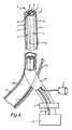
図4は、静脈1に接続された本発明によるキットを示す。前記キットは、本発明による医療デバイスを含み、この医療デバイスにおいて、ファイバ本体7はシースデバイス2の第1のボア6内に配置されており、注入手段9はシースデバイス2の第2のボア8内に配置されている。前記キットは、また、医療流体10用の容器と、調整手段11と、を含み、これらは、シースデバイス2の近位端4に、皮膚16内における静脈1への入口ポートを構成するイントロデューサシース15に近接して体外的に配置されている。イントロデューサシース15は実際には、上述のセルディンガー法などにおいて静脈1へのアクセスを得るために初めに使用したより長いイントロデューサシースの残りの部分である。前記イントロデューサシース15には、また、その遠位端に逆止弁(図4には示さず)が設けられてもよく、遠位端は、更には、例えば、リンス溶液、薬液等の任意の添加を行う目的で、導管(図4には示さず)を介して3方向弁に接続されていてもよい。注入手段9はその近位端が医療流体10用の容器と流体的に接続されている。麻酔治療のための静脈への医療流体の流れは医療流体10用の容器とイントロデューサシース15との間で接続されている調整手段11によって調整される。前記調整手段11は任意の従来のフローレギュレータ又は既定の流体量を提供する投与デバイスであってもよいが、一実施形態においては、引き金を有するピストルである。医療流体を圧送するためのポンプ(図4には示さず)もまた、医療流体10用の容器と調整手段11とに接続されている。 FIG. 4 shows a kit according to the invention connected to the
ファイバ本体7の近位端はシースデバイス2の溝付開口部5から体外に突出し、レーザ又は高周波アブレーション治療の発生器17に直接接続されている。 The proximal end of the
上で開示した麻酔工程が実施され、注入手段9を含むシースデバイス2が麻酔をかけられた血管、体腔又は体管から完全に引き戻された後、レーザ又は高周波アブレーション治療が開始される。 After the anesthesia process disclosed above is performed and the
レーザ又は高周波アブレーション治療時、ファイバ本体7はまず、その初期位置から近位方向に短い距離、例えば、約10mm引き戻される。これにより、シースデバイス2の遠位端の、初期麻酔工程時に適切に麻酔がかけられていない、治療されるべき血管、体腔又は体管の一部を焼灼するリスクが低下する。発生器17がオンにされ、その後、ファイバ本体7がある速度で近位方向に手動で又は自動的に引き戻される。一実施形態においては、引き戻し速度は約70J/cmである。引き戻し動作は手動で実施され、レーザ発生器17のオン及びオフの設定はフットペダルで制御されてもよい。更に、ファイバ本体7に提供されたセンチメートルスケールが正確な引き戻し速度を容易にしてもよい。焼灼プロセスは、また、超音波により追跡されてもよい。焼灼工程後、ファイバ本体は焼灼後の血管、体腔又は体管から完全に抜去される。 During laser or radio frequency ablation treatment, the
焼灼治療中、更なる麻酔が必要なことが判明した場合、シースデバイス2は溝付開口部5の隙間を通してファイバ本体7上に体外でスナップ留めされる又はクランプされる。その後、シースデバイス2及び注入手段9はイントロデューサシース15を通じて血管、体腔又は体管内に再導入され、ファイバ本体7上を摺動し、その後、麻酔工程が所望の程度まで繰り返される。溝付開口部5の使用によるシースデバイス2及びファイバ本体7のこのような簡単且つ迅速な再構成の実現性は本発明の大きな利点であり、焼灼プロセス全体を台無しにする、術者による更なる面倒な処置を不要にする。 If it is found during the cauterization treatment that further anesthesia is required, the
シースデバイス2の近位端4もまた、皮膚16内に血管、体腔又は体管への入口ポートを構成するイントロデューサシース15を通じて体外に突出する。上で開示したように、シースデバイス2と、第2のボア8内にある注入手段9との引き戻しは各注入工程の間で段階的に行われ、術者はシースデバイス2及び注入手段9を制御された手法で外側から引き戻してもよい。引き戻しの精度は体外超音波誘導によって従来の手法で決定され得る。更に、及びまた上で開示したように、シースデバイス2及び注入手段9の引き戻し時、麻酔をかける血管、体腔又は体管に不均一に麻酔をかけるのを回避する目的で、シースデバイス2及び注入手段9は水平面内においてある角度で回転させることができる。焼灼プロセスの終了時、イントロデューサシース15もまた静脈1から引き戻され、イントロデューサシース15によって覆われていた静脈1の内部表面の部分がここで開放され、利用可能になり、その後、これら内部表面も治療されるまでファイバ本体7による焼灼治療が施される。その後、焼灼プロセスは完全に完了し、ファイバ本体7は患者から抜去され、これに続いて、患者の皮膚の開口部を覆う。 The proximal end 4 of the
本発明による医療デバイス及びキットを、何らかの理由で病理学的、機能不全又は異常状態に曝された欠陥のある血管、体腔及び体管の治療に関連して使用してもよい。欠陥のある血管の例としては、主として静脈、特に、拡張蛇行静脈の原因となる不全表在静脈幹である。動脈にもまた、本発明による焼灼治療の方法を施してもよい。欠陥のある体腔の例は、嚢、瘻及び腫瘍である。本発明による焼灼治療の方法が施されてもよい欠陥のある体管の例は、気管支、胆管、尿路及び胃腸管である。図に示されている好適な実施形態では、本発明による医療デバイス及びキットは、不全表在静脈幹に起因する拡張蛇行静脈の治療に関連して使用される。 The medical devices and kits according to the present invention may be used in connection with the treatment of defective blood vessels, body cavities and body vessels that have been exposed to pathological, dysfunctional or abnormal conditions for any reason. An example of a defective blood vessel is a failing superficial venous trunk that primarily causes veins, particularly dilated serpentine veins. Arteries may also be subjected to the method of ablation treatment according to the present invention. Examples of defective body cavities are sac, fold and tumor. Examples of defective body vessels that may be subjected to the method of ablation treatment according to the present invention are bronchi, bile ducts, urinary tract and gastrointestinal tract. In the preferred embodiment shown in the figures, the medical devices and kits according to the present invention are used in connection with the treatment of dilated serpentine veins due to defective superficial vein trunks.
本発明による医療デバイスによって、前記欠陥のある血管、体腔及び体管の周囲の組織中に任意の医療流体を注入及び堆積させることが可能である。本発明による方法に関連して注入される医療流体は、欠陥のある血管、体腔、体管及び腫瘍の焼灼治療において有用であり得るもののいずれかであってもよく、麻酔工程は、また、焼灼以外の目的にも含まれる。一実施形態においては、医療流体は体組織の故意の膨化又は膨脹を生じさせる機能を有する従来の膨脹流体である。一実施形態においては、医療流体は従来の膨脹流体であると同時に従来の麻酔流体であり、すなわち、膨脹及び麻酔作用の両方を同時に有する。麻酔流体ではない膨脹流体の一例は塩化ナトリウム溶液である。同時に、膨脹流体ではない一例はカルボカインである。同じく同時に、麻酔流体である膨脹流体の一例は塩化ナトリウムとカルボカインとの混合溶液である。一実施形態においては、医療流体は癌腫瘍の治療のために使用される任意の細胞増殖抑制剤であり得る。前記細胞増殖抑制剤は前記周囲組織に注入される。一実施形態においては、医療流体は望ましくない組織の破壊のために使用される硬化薬流体であり、前記硬化薬流体は前記周囲組織に注入され、前記組織の破壊を引き起こす。本発明は拡張蛇行静脈の焼灼治療の図面を参照して開示してきたが、本明細書で開示される他の医療用途の治療を、任意選択的にファイバ本体7のない医療デバイス、キット及び方法ステップを同様の手法で使用することによって実施してもよい。 With the medical device according to the present invention, it is possible to inject and deposit any medical fluid into the defective blood vessels, body cavities and tissues surrounding the body tube. The medical fluid infused in connection with the method according to the present invention may be any of those that may be useful in the treatment of defective blood vessels, body cavities, body tubes and tumors, and the anesthesia process may also It is also included for other purposes. In one embodiment, the medical fluid is a conventional inflation fluid that functions to cause intentional swelling or expansion of body tissue. In one embodiment, the medical fluid is a conventional anesthetic fluid as well as a conventional anesthetic fluid, i.e., having both expansion and anesthetic action simultaneously. An example of an inflation fluid that is not an anesthetic fluid is a sodium chloride solution. At the same time, an example that is not an inflating fluid is carbocaine. At the same time, an example of an inflation fluid that is an anesthetic fluid is a mixed solution of sodium chloride and carbocaine. In one embodiment, the medical fluid can be any cytostatic agent used for the treatment of cancer tumors. The cytostatic agent is injected into the surrounding tissue. In one embodiment, the medical fluid is a sclerosing fluid used for unwanted tissue destruction, and the sclerosing fluid is injected into the surrounding tissue, causing destruction of the tissue. Although the present invention has been disclosed with reference to the drawings of dilated serpentine vein ablation treatments, the medical devices, kits and methods, optionally without the
いくつかの実施形態を参照して本発明を記載してきたが、当業者には、本発明の範囲から逸脱することなく種々の変更を施してもよく、且つ均等物をその要素に置換してもよいことは理解されよう。加えて、特定の状況又は材料を本発明の教示に適応させるために、その必須の範囲から逸脱することなく、多くの修正を施してもよい。したがって、本発明は、本発明を実施するために企図される最良実施態様として開示される特定の実施形態に限定されず、本発明は、添付の特許請求の範囲の範囲内にあるあらゆる実施形態を含むものとする。 Although the invention has been described with reference to several embodiments, various modifications may be made by those skilled in the art without departing from the scope of the invention, and equivalents may be substituted for the elements. It will be appreciated. In addition, many modifications may be made to adapt a particular situation or material to the teachings of the invention without departing from the essential scope thereof. Accordingly, the invention is not limited to the specific embodiments disclosed as the best mode contemplated for practicing the invention, and the invention is not limited to any embodiment that falls within the scope of the appended claims. Shall be included.
Claims (22)
Translated fromJapanesea)請求項1に記載の医療デバイスと、前記ファイバ本体(7)と、前記注入手段(9)とを血管、体腔又は体管の内腔(14)内に既定の位置に達するまで挿入するステップであって、前記ファイバ本体(7)は第1のボア(6)を通じて挿入され、前記注入手段は第2のボア(8)を通じて挿入される、ステップと、
b)前記注入手段(9)を前記第2のボア(8)から押し出すステップであって、前記注入手段(9)の針先端部は径方向に逸れ、前記血管、体腔又は体管の壁を貫通し、血管周囲組織(13)又は前記周囲組織に達する、ステップと、
c)前記血管周囲組織(13)又は前記周囲組織に医療流体を注入するステップと、
d)前記注入手段(9)を前記第2のボア(8)へと引き戻すステップと、
e)前記シースデバイス(2)と前記注入手段(9)とを新たな既定の注入部位に達するまで近位方向に引き戻すステップであって、前記ファイバ本体(7)は引き戻されない、ステップと、
f)前記血管、体腔又は体管の前記壁、及び前記血管、体腔若しくは体管の全部分に沿う前記血管周囲組織(13)又は前記周囲組織に麻酔がかけられるまでステップb)〜e)を繰り返すステップと、
g)前記シースデバイス(2)と前記注入手段(9)とを前記血管、体腔又は体管の前記内腔(14)から除去するステップと、
h)前記ファイバ本体(7)の使用によって前記血管、体腔又は体管の前記内壁の焼灼治療を実施するステップであって、前記ファイバ本体(7)は、治療されるべき前記血管、体腔又は体管の前記内壁表面の全部分に前記焼灼治療が施されるまで、前記内腔(14)内において近位方向に段階的に引き戻される、ステップと、
i)前記ファイバ本体(7)を前記血管、体腔又は体管の前記内腔(14)から抜去するステップと、を含み、
前記医療流体は膨脹及び/又は麻酔作用を有し、
前記方法は、前記組織中に医療流体を堆積させる場合、上記の少なくとも方法ステップa)〜f)における、任意選択的に前記ファイバ本体(7)なしでの、請求項1に記載の医療デバイス又は請求項10に記載のキットの使用を含み、前記医療流体は、好ましくは、膨脹及び/若しくは麻酔作用、細胞増殖抑制性作用又は硬化作用を有する流体であることを特徴とする方法。A method for the ablation treatment of defective blood vessels, body cavities and body ducts, preferably dilating serpentine veins, or for depositing medical fluid in the tissues surrounding the defective blood vessels, body cavities and body ducts, comprising: In the case of ablation treatment,
a) Insert the medical device according to claim 1, the fiber body (7) and the injection means (9) into a blood vessel, body cavity or body lumen (14) until a predetermined position is reached. The fiber body (7) is inserted through a first bore (6) and the injection means is inserted through a second bore (8);
b) extruding the injection means (9) from the second bore (8), the tip of the needle of the injection means (9) deviating in the radial direction, and the wall of the blood vessel, body cavity or body tube Penetrating and reaching the perivascular tissue (13) or the surrounding tissue;
c) injecting a medical fluid into the perivascular tissue (13) or the surrounding tissue;
d) pulling back the injection means (9) into the second bore (8);
e) pulling back the sheath device (2) and the injection means (9) in a proximal direction until a new predetermined injection site is reached, wherein the fiber body (7) is not pulled back;
f) Steps b) -e) until the blood vessel, the body cavity or the wall of the body tube and the perivascular tissue (13) or the surrounding tissue along the whole part of the blood vessel, body cavity or body tube are anesthetized. Repeating steps,
g) removing the sheath device (2) and the injection means (9) from the lumen (14) of the blood vessel, body cavity or body tube;
h) performing an ablation treatment of the inner wall of the blood vessel, body cavity or body tube by use of the fiber body (7), wherein the fiber body (7) is the blood vessel, body cavity or body to be treated; Being stepped back in a proximal direction within the lumen (14) until the entire portion of the inner wall surface of the tube is subjected to the ablation treatment;
i) withdrawing the fiber body (7) from the lumen (14) of the blood vessel, body cavity or body tube;
The medical fluid has an expansion and / or anesthetic action;
The medical device according to claim 1, wherein said method optionally deposits medical fluid in said tissue, optionally without said fiber body (7) in at least method steps a) to f) above. 11. A method comprising the use of a kit according to claim 10, characterized in that the medical fluid is preferably a fluid having swelling and / or anesthetic action, cytostatic action or hardening action.
Applications Claiming Priority (3)
| Application Number | Priority Date | Filing Date | Title |
|---|---|---|---|
| SE1451384-0 | 2014-11-18 | ||
| SE1451384ASE1451384A1 (en) | 2014-11-18 | 2014-11-18 | Medical device for ablation treatment of defective blood vessels, body cavities, and body ducts |
| PCT/SE2015/051234WO2016080896A1 (en) | 2014-11-18 | 2015-11-17 | Medical device for treatment of defective blood vessels, body cavities, and body ducts |
Publications (2)
| Publication Number | Publication Date |
|---|---|
| JP2017535394Atrue JP2017535394A (en) | 2017-11-30 |
| JP2017535394A5 JP2017535394A5 (en) | 2018-12-27 |
Family
ID=55809387
Family Applications (1)
| Application Number | Title | Priority Date | Filing Date |
|---|---|---|---|
| JP2017545518APendingJP2017535394A (en) | 2014-11-18 | 2015-11-17 | Medical device for treating defective blood vessels, body cavities and body vessels |
Country Status (10)
| Country | Link |
|---|---|
| US (1) | US10881460B2 (en) |
| EP (1) | EP3220845B1 (en) |
| JP (1) | JP2017535394A (en) |
| CN (1) | CN107106237B (en) |
| AU (1) | AU2015350629B2 (en) |
| BR (1) | BR112017010242B1 (en) |
| CA (1) | CA2968034C (en) |
| RU (1) | RU2712089C2 (en) |
| SE (1) | SE1451384A1 (en) |
| WO (1) | WO2016080896A1 (en) |
Families Citing this family (4)
| Publication number | Priority date | Publication date | Assignee | Title |
|---|---|---|---|---|
| CN114869386B (en)* | 2022-05-06 | 2024-11-05 | 上海畅德医疗科技有限公司 | Varicose vein closure surgery delivery system device and delivery method thereof |
| CN115025366B (en)* | 2022-07-01 | 2023-04-11 | 惠州市顺美医疗科技有限公司 | Medical catheter and rotary cutting method thereof |
| CN115194886B (en)* | 2022-07-14 | 2023-07-25 | 惠州市顺美医疗科技有限公司 | Advanced small catheter and preparation method thereof |
| WO2024016170A1 (en)* | 2022-07-19 | 2024-01-25 | 上海诺英医疗器械有限公司 | Data monitoring system |
Citations (3)
| Publication number | Priority date | Publication date | Assignee | Title |
|---|---|---|---|---|
| US20050278010A1 (en)* | 2004-05-27 | 2005-12-15 | Scimed Life Systems, Inc. | Stent delivery system with imaging capability |
| WO2007102586A1 (en)* | 2006-03-09 | 2007-09-13 | Olympus Medical Systems Corp. | Treatment instrument for endoscope |
| US20090222003A1 (en)* | 2005-11-10 | 2009-09-03 | Otley Clark C | Vein closure and injection kits and methods |
Family Cites Families (20)
| Publication number | Priority date | Publication date | Assignee | Title |
|---|---|---|---|---|
| FR2597744A1 (en) | 1986-04-29 | 1987-10-30 | Boussignac Georges | CARDIO-VASCULAR CATHETER FOR LASER SHOOTING |
| US5709676A (en)* | 1990-02-14 | 1998-01-20 | Alt; Eckhard | Synergistic treatment of stenosed blood vessels using shock waves and dissolving medication |
| CN1204242A (en) | 1995-10-13 | 1999-01-06 | 血管转换公司 | Methods and devices for bypassing and/or other transvascular procedures for arterial blockages |
| US5891154A (en) | 1997-05-06 | 1999-04-06 | Advanced Cardiovascular System, Inc. | Passive perfusion stent delivery system |
| US20030032936A1 (en)* | 2001-08-10 | 2003-02-13 | Lederman Robert J. | Side-exit catheter and method for its use |
| US7163533B2 (en) | 2002-04-04 | 2007-01-16 | Angiodynamics, Inc. | Vascular treatment device and method |
| US20040254528A1 (en)* | 2003-06-12 | 2004-12-16 | Adams Daniel O. | Catheter with removable wire lumen segment |
| JP5046931B2 (en)* | 2004-08-05 | 2012-10-10 | タイコ ヘルスケア グループ リミテッド パートナーシップ | Method and apparatus for coagulating and / or constricting hollow anatomical structures |
| EP1827555A4 (en) | 2004-11-18 | 2010-03-10 | David W Chang | Endoluminal delivery of anesthesia |
| US8597260B2 (en)* | 2004-12-16 | 2013-12-03 | Smiths Medical Asd, Inc. | Catheter with direction orientation |
| US8562566B2 (en) | 2005-02-28 | 2013-10-22 | Boston Scientific Scimed, Inc. | Stent delivery and guidewire guidance system |
| WO2007002304A2 (en)* | 2005-06-22 | 2007-01-04 | Vnus Medical Technologies, Inc. | Methods and apparatus for introducing tumescent fluid to body tissue |
| ES2469593T3 (en) | 2006-03-13 | 2014-06-18 | Bruno Anastasie | Laser instrument, applicable to vascular occlusion particularly for intravenous treatment as well as perforation or tissue detersion |
| US20090131924A1 (en) | 2007-11-16 | 2009-05-21 | Meyer Ralph A | Endovascular Thermal Treatment Device with Carrier Wire and Method |
| US9693826B2 (en) | 2008-02-28 | 2017-07-04 | Biolitec Unternehmensbeteiligungs Ii Ag | Endoluminal laser ablation device and method for treating veins |
| EP2295996B1 (en) | 2009-08-07 | 2011-09-28 | Omicron electronics GmbH | System for monitoring a transformer |
| JP2015511137A (en)* | 2012-01-30 | 2015-04-16 | ビトロンユーエス, インコーポレイテッド | Tissue necrosis method and apparatus |
| US10272269B2 (en) | 2012-11-13 | 2019-04-30 | Silk Road Medical, Inc. | Devices and methods for endoluminal delivery of either fluid or energy for denervation |
| CN106061420B (en) | 2013-10-25 | 2021-12-07 | 消融系统有限公司 | Intravascular catheter with perivascular nerve activity sensor |
| CN103800977A (en)* | 2014-01-27 | 2014-05-21 | 广西壮族自治区人民医院 | Optical fiber for administration |
- 2014
- 2014-11-18SESE1451384Apatent/SE1451384A1/enunknown
- 2015
- 2015-11-17WOPCT/SE2015/051234patent/WO2016080896A1/enactiveApplication Filing
- 2015-11-17CACA2968034Apatent/CA2968034C/enactiveActive
- 2015-11-17EPEP15861222.6Apatent/EP3220845B1/enactiveActive
- 2015-11-17JPJP2017545518Apatent/JP2017535394A/enactivePending
- 2015-11-17USUS15/526,945patent/US10881460B2/enactiveActive
- 2015-11-17RURU2017120473Apatent/RU2712089C2/enactive
- 2015-11-17CNCN201580073400.8Apatent/CN107106237B/enactiveActive
- 2015-11-17AUAU2015350629Apatent/AU2015350629B2/enactiveActive
- 2015-11-17BRBR112017010242-0Apatent/BR112017010242B1/enactiveIP Right Grant
Patent Citations (3)
| Publication number | Priority date | Publication date | Assignee | Title |
|---|---|---|---|---|
| US20050278010A1 (en)* | 2004-05-27 | 2005-12-15 | Scimed Life Systems, Inc. | Stent delivery system with imaging capability |
| US20090222003A1 (en)* | 2005-11-10 | 2009-09-03 | Otley Clark C | Vein closure and injection kits and methods |
| WO2007102586A1 (en)* | 2006-03-09 | 2007-09-13 | Olympus Medical Systems Corp. | Treatment instrument for endoscope |
Also Published As
| Publication number | Publication date |
|---|---|
| CN107106237B (en) | 2023-04-04 |
| RU2712089C2 (en) | 2020-01-24 |
| AU2015350629A1 (en) | 2017-06-01 |
| BR112017010242A2 (en) | 2018-02-14 |
| US10881460B2 (en) | 2021-01-05 |
| EP3220845B1 (en) | 2021-06-16 |
| SE538305C2 (en) | 2016-05-03 |
| CA2968034A1 (en) | 2016-05-26 |
| EP3220845A4 (en) | 2018-08-15 |
| CA2968034C (en) | 2023-02-14 |
| SE1451384A1 (en) | 2016-05-03 |
| CN107106237A (en) | 2017-08-29 |
| US20170333130A1 (en) | 2017-11-23 |
| WO2016080896A1 (en) | 2016-05-26 |
| EP3220845A1 (en) | 2017-09-27 |
| BR112017010242B1 (en) | 2023-01-17 |
| AU2015350629B2 (en) | 2020-04-16 |
| RU2017120473A (en) | 2018-12-19 |
| RU2017120473A3 (en) | 2019-05-24 |
Similar Documents
| Publication | Publication Date | Title |
|---|---|---|
| JP7657876B2 (en) | Perivascular tissue ablation catheter with support structure - Patents.com | |
| US10828460B2 (en) | Endoluminal delivery of anesthesia | |
| US5693029A (en) | Pro-cell intra-cavity therapeutic agent delivery device | |
| JP4871486B2 (en) | Winding route injection device and injection method | |
| US9055956B2 (en) | Methods and apparatus for introducing tumescent fluid to body tissue | |
| US7163533B2 (en) | Vascular treatment device and method | |
| US7621895B2 (en) | Needle array devices and methods | |
| KR102080330B1 (en) | Varicose vein surgery kit and surgical method using the same | |
| JP2014500762A (en) | Vascular treatment apparatus and method | |
| CN104043182A (en) | Fluid delivery catheter with pressure-actuating needle deployment and retraction | |
| US20040193103A1 (en) | Apparatus and method for sclerosing the wall of a blood vessel | |
| US11596473B2 (en) | Medical device for treating a vein | |
| JP2017535394A (en) | Medical device for treating defective blood vessels, body cavities and body vessels | |
| CA2942230C (en) | Medical device comprising a hydrophilic curved flexible tip for the treatment of varicose veins | |
| US20180280671A1 (en) | Device for treating venous incompetence, and related methods | |
| KR20210152909A (en) | Thermochemical lower extremity varicose veins surgical kit and method of use | |
| US20130268036A1 (en) | Apparatus and Method of Treating a Vein with Heat Energy |
Legal Events
| Date | Code | Title | Description |
|---|---|---|---|
| A521 | Request for written amendment filed | Free format text:JAPANESE INTERMEDIATE CODE: A523 Effective date:20181115 | |
| A621 | Written request for application examination | Free format text:JAPANESE INTERMEDIATE CODE: A621 Effective date:20181115 | |
| A131 | Notification of reasons for refusal | Free format text:JAPANESE INTERMEDIATE CODE: A131 Effective date:20190917 | |
| A977 | Report on retrieval | Free format text:JAPANESE INTERMEDIATE CODE: A971007 Effective date:20190918 | |
| A521 | Request for written amendment filed | Free format text:JAPANESE INTERMEDIATE CODE: A523 Effective date:20191217 | |
| A02 | Decision of refusal | Free format text:JAPANESE INTERMEDIATE CODE: A02 Effective date:20200526 |