JP2017528354A - UAV energy exchange station - Google Patents
UAV energy exchange stationDownload PDFInfo
- Publication number
- JP2017528354A JP2017528354AJP2016571039AJP2016571039AJP2017528354AJP 2017528354 AJP2017528354 AJP 2017528354AJP 2016571039 AJP2016571039 AJP 2016571039AJP 2016571039 AJP2016571039 AJP 2016571039AJP 2017528354 AJP2017528354 AJP 2017528354A
- Authority
- JP
- Japan
- Prior art keywords
- uav
- battery
- station
- exchange station
- energy supply
- Prior art date
- Legal status (The legal status is an assumption and is not a legal conclusion. Google has not performed a legal analysis and makes no representation as to the accuracy of the status listed.)
- Granted
Links
Images


Classifications
- B—PERFORMING OPERATIONS; TRANSPORTING
- B60—VEHICLES IN GENERAL
- B60L—PROPULSION OF ELECTRICALLY-PROPELLED VEHICLES; SUPPLYING ELECTRIC POWER FOR AUXILIARY EQUIPMENT OF ELECTRICALLY-PROPELLED VEHICLES; ELECTRODYNAMIC BRAKE SYSTEMS FOR VEHICLES IN GENERAL; MAGNETIC SUSPENSION OR LEVITATION FOR VEHICLES; MONITORING OPERATING VARIABLES OF ELECTRICALLY-PROPELLED VEHICLES; ELECTRIC SAFETY DEVICES FOR ELECTRICALLY-PROPELLED VEHICLES
- B60L53/00—Methods of charging batteries, specially adapted for electric vehicles; Charging stations or on-board charging equipment therefor; Exchange of energy storage elements in electric vehicles
- B60L53/80—Exchanging energy storage elements, e.g. removable batteries
- B—PERFORMING OPERATIONS; TRANSPORTING
- B60—VEHICLES IN GENERAL
- B60L—PROPULSION OF ELECTRICALLY-PROPELLED VEHICLES; SUPPLYING ELECTRIC POWER FOR AUXILIARY EQUIPMENT OF ELECTRICALLY-PROPELLED VEHICLES; ELECTRODYNAMIC BRAKE SYSTEMS FOR VEHICLES IN GENERAL; MAGNETIC SUSPENSION OR LEVITATION FOR VEHICLES; MONITORING OPERATING VARIABLES OF ELECTRICALLY-PROPELLED VEHICLES; ELECTRIC SAFETY DEVICES FOR ELECTRICALLY-PROPELLED VEHICLES
- B60L53/00—Methods of charging batteries, specially adapted for electric vehicles; Charging stations or on-board charging equipment therefor; Exchange of energy storage elements in electric vehicles
- B60L53/10—Methods of charging batteries, specially adapted for electric vehicles; Charging stations or on-board charging equipment therefor; Exchange of energy storage elements in electric vehicles characterised by the energy transfer between the charging station and the vehicle
- B60L53/14—Conductive energy transfer
- B—PERFORMING OPERATIONS; TRANSPORTING
- B60—VEHICLES IN GENERAL
- B60L—PROPULSION OF ELECTRICALLY-PROPELLED VEHICLES; SUPPLYING ELECTRIC POWER FOR AUXILIARY EQUIPMENT OF ELECTRICALLY-PROPELLED VEHICLES; ELECTRODYNAMIC BRAKE SYSTEMS FOR VEHICLES IN GENERAL; MAGNETIC SUSPENSION OR LEVITATION FOR VEHICLES; MONITORING OPERATING VARIABLES OF ELECTRICALLY-PROPELLED VEHICLES; ELECTRIC SAFETY DEVICES FOR ELECTRICALLY-PROPELLED VEHICLES
- B60L53/00—Methods of charging batteries, specially adapted for electric vehicles; Charging stations or on-board charging equipment therefor; Exchange of energy storage elements in electric vehicles
- B60L53/30—Constructional details of charging stations
- B60L53/31—Charging columns specially adapted for electric vehicles
- B—PERFORMING OPERATIONS; TRANSPORTING
- B60—VEHICLES IN GENERAL
- B60L—PROPULSION OF ELECTRICALLY-PROPELLED VEHICLES; SUPPLYING ELECTRIC POWER FOR AUXILIARY EQUIPMENT OF ELECTRICALLY-PROPELLED VEHICLES; ELECTRODYNAMIC BRAKE SYSTEMS FOR VEHICLES IN GENERAL; MAGNETIC SUSPENSION OR LEVITATION FOR VEHICLES; MONITORING OPERATING VARIABLES OF ELECTRICALLY-PROPELLED VEHICLES; ELECTRIC SAFETY DEVICES FOR ELECTRICALLY-PROPELLED VEHICLES
- B60L58/00—Methods or circuit arrangements for monitoring or controlling batteries or fuel cells, specially adapted for electric vehicles
- B60L58/10—Methods or circuit arrangements for monitoring or controlling batteries or fuel cells, specially adapted for electric vehicles for monitoring or controlling batteries
- B60L58/12—Methods or circuit arrangements for monitoring or controlling batteries or fuel cells, specially adapted for electric vehicles for monitoring or controlling batteries responding to state of charge [SoC]
- B—PERFORMING OPERATIONS; TRANSPORTING
- B64—AIRCRAFT; AVIATION; COSMONAUTICS
- B64F—GROUND OR AIRCRAFT-CARRIER-DECK INSTALLATIONS SPECIALLY ADAPTED FOR USE IN CONNECTION WITH AIRCRAFT; DESIGNING, MANUFACTURING, ASSEMBLING, CLEANING, MAINTAINING OR REPAIRING AIRCRAFT, NOT OTHERWISE PROVIDED FOR; HANDLING, TRANSPORTING, TESTING OR INSPECTING AIRCRAFT COMPONENTS, NOT OTHERWISE PROVIDED FOR
- B64F1/00—Ground or aircraft-carrier-deck installations
- B64F1/007—Helicopter portable landing pads
- B—PERFORMING OPERATIONS; TRANSPORTING
- B64—AIRCRAFT; AVIATION; COSMONAUTICS
- B64F—GROUND OR AIRCRAFT-CARRIER-DECK INSTALLATIONS SPECIALLY ADAPTED FOR USE IN CONNECTION WITH AIRCRAFT; DESIGNING, MANUFACTURING, ASSEMBLING, CLEANING, MAINTAINING OR REPAIRING AIRCRAFT, NOT OTHERWISE PROVIDED FOR; HANDLING, TRANSPORTING, TESTING OR INSPECTING AIRCRAFT COMPONENTS, NOT OTHERWISE PROVIDED FOR
- B64F1/00—Ground or aircraft-carrier-deck installations
- B64F1/02—Ground or aircraft-carrier-deck installations for arresting aircraft, e.g. nets or cables
- B64F1/0297—Ground or aircraft-carrier-deck installations for arresting aircraft, e.g. nets or cables adjustable to align with aircraft trajectory
- B—PERFORMING OPERATIONS; TRANSPORTING
- B64—AIRCRAFT; AVIATION; COSMONAUTICS
- B64F—GROUND OR AIRCRAFT-CARRIER-DECK INSTALLATIONS SPECIALLY ADAPTED FOR USE IN CONNECTION WITH AIRCRAFT; DESIGNING, MANUFACTURING, ASSEMBLING, CLEANING, MAINTAINING OR REPAIRING AIRCRAFT, NOT OTHERWISE PROVIDED FOR; HANDLING, TRANSPORTING, TESTING OR INSPECTING AIRCRAFT COMPONENTS, NOT OTHERWISE PROVIDED FOR
- B64F1/00—Ground or aircraft-carrier-deck installations
- B64F1/18—Visual or acoustic landing aids
- B64F1/20—Arrangement of optical beacons
- B—PERFORMING OPERATIONS; TRANSPORTING
- B64—AIRCRAFT; AVIATION; COSMONAUTICS
- B64U—UNMANNED AERIAL VEHICLES [UAV]; EQUIPMENT THEREFOR
- B64U50/00—Propulsion; Power supply
- B64U50/30—Supply or distribution of electrical power
- B64U50/39—Battery swapping
- G—PHYSICS
- G05—CONTROLLING; REGULATING
- G05D—SYSTEMS FOR CONTROLLING OR REGULATING NON-ELECTRIC VARIABLES
- G05D1/00—Control of position, course, altitude or attitude of land, water, air or space vehicles, e.g. using automatic pilots
- G05D1/0011—Control of position, course, altitude or attitude of land, water, air or space vehicles, e.g. using automatic pilots associated with a remote control arrangement
- G—PHYSICS
- G05—CONTROLLING; REGULATING
- G05D—SYSTEMS FOR CONTROLLING OR REGULATING NON-ELECTRIC VARIABLES
- G05D1/00—Control of position, course, altitude or attitude of land, water, air or space vehicles, e.g. using automatic pilots
- G05D1/10—Simultaneous control of position or course in three dimensions
- G05D1/101—Simultaneous control of position or course in three dimensions specially adapted for aircraft
- G05D1/102—Simultaneous control of position or course in three dimensions specially adapted for aircraft specially adapted for vertical take-off of aircraft
- B—PERFORMING OPERATIONS; TRANSPORTING
- B60—VEHICLES IN GENERAL
- B60L—PROPULSION OF ELECTRICALLY-PROPELLED VEHICLES; SUPPLYING ELECTRIC POWER FOR AUXILIARY EQUIPMENT OF ELECTRICALLY-PROPELLED VEHICLES; ELECTRODYNAMIC BRAKE SYSTEMS FOR VEHICLES IN GENERAL; MAGNETIC SUSPENSION OR LEVITATION FOR VEHICLES; MONITORING OPERATING VARIABLES OF ELECTRICALLY-PROPELLED VEHICLES; ELECTRIC SAFETY DEVICES FOR ELECTRICALLY-PROPELLED VEHICLES
- B60L2200/00—Type of vehicles
- B60L2200/10—Air crafts
- B—PERFORMING OPERATIONS; TRANSPORTING
- B60—VEHICLES IN GENERAL
- B60L—PROPULSION OF ELECTRICALLY-PROPELLED VEHICLES; SUPPLYING ELECTRIC POWER FOR AUXILIARY EQUIPMENT OF ELECTRICALLY-PROPELLED VEHICLES; ELECTRODYNAMIC BRAKE SYSTEMS FOR VEHICLES IN GENERAL; MAGNETIC SUSPENSION OR LEVITATION FOR VEHICLES; MONITORING OPERATING VARIABLES OF ELECTRICALLY-PROPELLED VEHICLES; ELECTRIC SAFETY DEVICES FOR ELECTRICALLY-PROPELLED VEHICLES
- B60L2220/00—Electrical machine types; Structures or applications thereof
- B60L2220/40—Electrical machine applications
- B60L2220/42—Electrical machine applications with use of more than one motor
- B—PERFORMING OPERATIONS; TRANSPORTING
- B60—VEHICLES IN GENERAL
- B60L—PROPULSION OF ELECTRICALLY-PROPELLED VEHICLES; SUPPLYING ELECTRIC POWER FOR AUXILIARY EQUIPMENT OF ELECTRICALLY-PROPELLED VEHICLES; ELECTRODYNAMIC BRAKE SYSTEMS FOR VEHICLES IN GENERAL; MAGNETIC SUSPENSION OR LEVITATION FOR VEHICLES; MONITORING OPERATING VARIABLES OF ELECTRICALLY-PROPELLED VEHICLES; ELECTRIC SAFETY DEVICES FOR ELECTRICALLY-PROPELLED VEHICLES
- B60L2240/00—Control parameters of input or output; Target parameters
- B60L2240/60—Navigation input
- B60L2240/66—Ambient conditions
- B60L2240/667—Precipitation
- B—PERFORMING OPERATIONS; TRANSPORTING
- B60—VEHICLES IN GENERAL
- B60L—PROPULSION OF ELECTRICALLY-PROPELLED VEHICLES; SUPPLYING ELECTRIC POWER FOR AUXILIARY EQUIPMENT OF ELECTRICALLY-PROPELLED VEHICLES; ELECTRODYNAMIC BRAKE SYSTEMS FOR VEHICLES IN GENERAL; MAGNETIC SUSPENSION OR LEVITATION FOR VEHICLES; MONITORING OPERATING VARIABLES OF ELECTRICALLY-PROPELLED VEHICLES; ELECTRIC SAFETY DEVICES FOR ELECTRICALLY-PROPELLED VEHICLES
- B60L2250/00—Driver interactions
- B60L2250/16—Driver interactions by display
- B—PERFORMING OPERATIONS; TRANSPORTING
- B64—AIRCRAFT; AVIATION; COSMONAUTICS
- B64U—UNMANNED AERIAL VEHICLES [UAV]; EQUIPMENT THEREFOR
- B64U10/00—Type of UAV
- B64U10/10—Rotorcrafts
- B64U10/13—Flying platforms
- B—PERFORMING OPERATIONS; TRANSPORTING
- B64—AIRCRAFT; AVIATION; COSMONAUTICS
- B64U—UNMANNED AERIAL VEHICLES [UAV]; EQUIPMENT THEREFOR
- B64U30/00—Means for producing lift; Empennages; Arrangements thereof
- B64U30/20—Rotors; Rotor supports
- B—PERFORMING OPERATIONS; TRANSPORTING
- B64—AIRCRAFT; AVIATION; COSMONAUTICS
- B64U—UNMANNED AERIAL VEHICLES [UAV]; EQUIPMENT THEREFOR
- B64U60/00—Undercarriages
- B64U60/50—Undercarriages with landing legs
- B—PERFORMING OPERATIONS; TRANSPORTING
- B64—AIRCRAFT; AVIATION; COSMONAUTICS
- B64U—UNMANNED AERIAL VEHICLES [UAV]; EQUIPMENT THEREFOR
- B64U70/00—Launching, take-off or landing arrangements
- B64U70/90—Launching from or landing on platforms
- Y—GENERAL TAGGING OF NEW TECHNOLOGICAL DEVELOPMENTS; GENERAL TAGGING OF CROSS-SECTIONAL TECHNOLOGIES SPANNING OVER SEVERAL SECTIONS OF THE IPC; TECHNICAL SUBJECTS COVERED BY FORMER USPC CROSS-REFERENCE ART COLLECTIONS [XRACs] AND DIGESTS
- Y02—TECHNOLOGIES OR APPLICATIONS FOR MITIGATION OR ADAPTATION AGAINST CLIMATE CHANGE
- Y02T—CLIMATE CHANGE MITIGATION TECHNOLOGIES RELATED TO TRANSPORTATION
- Y02T10/00—Road transport of goods or passengers
- Y02T10/60—Other road transportation technologies with climate change mitigation effect
- Y02T10/64—Electric machine technologies in electromobility
- Y—GENERAL TAGGING OF NEW TECHNOLOGICAL DEVELOPMENTS; GENERAL TAGGING OF CROSS-SECTIONAL TECHNOLOGIES SPANNING OVER SEVERAL SECTIONS OF THE IPC; TECHNICAL SUBJECTS COVERED BY FORMER USPC CROSS-REFERENCE ART COLLECTIONS [XRACs] AND DIGESTS
- Y02—TECHNOLOGIES OR APPLICATIONS FOR MITIGATION OR ADAPTATION AGAINST CLIMATE CHANGE
- Y02T—CLIMATE CHANGE MITIGATION TECHNOLOGIES RELATED TO TRANSPORTATION
- Y02T10/00—Road transport of goods or passengers
- Y02T10/60—Other road transportation technologies with climate change mitigation effect
- Y02T10/70—Energy storage systems for electromobility, e.g. batteries
- Y—GENERAL TAGGING OF NEW TECHNOLOGICAL DEVELOPMENTS; GENERAL TAGGING OF CROSS-SECTIONAL TECHNOLOGIES SPANNING OVER SEVERAL SECTIONS OF THE IPC; TECHNICAL SUBJECTS COVERED BY FORMER USPC CROSS-REFERENCE ART COLLECTIONS [XRACs] AND DIGESTS
- Y02—TECHNOLOGIES OR APPLICATIONS FOR MITIGATION OR ADAPTATION AGAINST CLIMATE CHANGE
- Y02T—CLIMATE CHANGE MITIGATION TECHNOLOGIES RELATED TO TRANSPORTATION
- Y02T10/00—Road transport of goods or passengers
- Y02T10/60—Other road transportation technologies with climate change mitigation effect
- Y02T10/7072—Electromobility specific charging systems or methods for batteries, ultracapacitors, supercapacitors or double-layer capacitors
- Y—GENERAL TAGGING OF NEW TECHNOLOGICAL DEVELOPMENTS; GENERAL TAGGING OF CROSS-SECTIONAL TECHNOLOGIES SPANNING OVER SEVERAL SECTIONS OF THE IPC; TECHNICAL SUBJECTS COVERED BY FORMER USPC CROSS-REFERENCE ART COLLECTIONS [XRACs] AND DIGESTS
- Y02—TECHNOLOGIES OR APPLICATIONS FOR MITIGATION OR ADAPTATION AGAINST CLIMATE CHANGE
- Y02T—CLIMATE CHANGE MITIGATION TECHNOLOGIES RELATED TO TRANSPORTATION
- Y02T10/00—Road transport of goods or passengers
- Y02T10/60—Other road transportation technologies with climate change mitigation effect
- Y02T10/72—Electric energy management in electromobility
- Y—GENERAL TAGGING OF NEW TECHNOLOGICAL DEVELOPMENTS; GENERAL TAGGING OF CROSS-SECTIONAL TECHNOLOGIES SPANNING OVER SEVERAL SECTIONS OF THE IPC; TECHNICAL SUBJECTS COVERED BY FORMER USPC CROSS-REFERENCE ART COLLECTIONS [XRACs] AND DIGESTS
- Y02—TECHNOLOGIES OR APPLICATIONS FOR MITIGATION OR ADAPTATION AGAINST CLIMATE CHANGE
- Y02T—CLIMATE CHANGE MITIGATION TECHNOLOGIES RELATED TO TRANSPORTATION
- Y02T90/00—Enabling technologies or technologies with a potential or indirect contribution to GHG emissions mitigation
- Y02T90/10—Technologies relating to charging of electric vehicles
- Y02T90/12—Electric charging stations
- Y—GENERAL TAGGING OF NEW TECHNOLOGICAL DEVELOPMENTS; GENERAL TAGGING OF CROSS-SECTIONAL TECHNOLOGIES SPANNING OVER SEVERAL SECTIONS OF THE IPC; TECHNICAL SUBJECTS COVERED BY FORMER USPC CROSS-REFERENCE ART COLLECTIONS [XRACs] AND DIGESTS
- Y02—TECHNOLOGIES OR APPLICATIONS FOR MITIGATION OR ADAPTATION AGAINST CLIMATE CHANGE
- Y02T—CLIMATE CHANGE MITIGATION TECHNOLOGIES RELATED TO TRANSPORTATION
- Y02T90/00—Enabling technologies or technologies with a potential or indirect contribution to GHG emissions mitigation
- Y02T90/10—Technologies relating to charging of electric vehicles
- Y02T90/14—Plug-in electric vehicles
- Y—GENERAL TAGGING OF NEW TECHNOLOGICAL DEVELOPMENTS; GENERAL TAGGING OF CROSS-SECTIONAL TECHNOLOGIES SPANNING OVER SEVERAL SECTIONS OF THE IPC; TECHNICAL SUBJECTS COVERED BY FORMER USPC CROSS-REFERENCE ART COLLECTIONS [XRACs] AND DIGESTS
- Y02—TECHNOLOGIES OR APPLICATIONS FOR MITIGATION OR ADAPTATION AGAINST CLIMATE CHANGE
- Y02T—CLIMATE CHANGE MITIGATION TECHNOLOGIES RELATED TO TRANSPORTATION
- Y02T90/00—Enabling technologies or technologies with a potential or indirect contribution to GHG emissions mitigation
- Y02T90/10—Technologies relating to charging of electric vehicles
- Y02T90/16—Information or communication technologies improving the operation of electric vehicles
Landscapes
- Engineering & Computer Science (AREA)
- Mechanical Engineering (AREA)
- Aviation & Aerospace Engineering (AREA)
- Power Engineering (AREA)
- Transportation (AREA)
- Physics & Mathematics (AREA)
- Acoustics & Sound (AREA)
- Radar, Positioning & Navigation (AREA)
- Remote Sensing (AREA)
- General Physics & Mathematics (AREA)
- Automation & Control Theory (AREA)
- Sustainable Development (AREA)
- Sustainable Energy (AREA)
- Life Sciences & Earth Sciences (AREA)
- Chemical & Material Sciences (AREA)
- Combustion & Propulsion (AREA)
- Charge And Discharge Circuits For Batteries Or The Like (AREA)
- Secondary Cells (AREA)
- Control Of Position, Course, Altitude, Or Attitude Of Moving Bodies (AREA)
- Electric Propulsion And Braking For Vehicles (AREA)
Abstract
Translated fromJapaneseDescription
Translated fromJapanese無人航空機(UAV)のような航空機は、軍隊および民間用途の監視、偵察、および探査任務を実行するために使用されることができる。そのような航空機は、特定の機能を実行するように構成された積載物を運んでよい。 Aircraft such as unmanned aerial vehicles (UAVs) can be used to perform military, civilian surveillance, reconnaissance, and exploration missions. Such an aircraft may carry a load configured to perform a specific function.
UAVは、搭載された充電式バッテリーによって電力を供給されてよい。場合によってUAVは、搭載されているバッテリーで利用可能な充電量を超えるであろう距離を移動する必要があるかもしれない。これは、UAVの範囲および用途を厳しく制限するかもしれない。 The UAV may be powered by an onboard rechargeable battery. In some cases, the UAV may need to travel a distance that would exceed the amount of charge available on the onboard battery. This may severely limit the scope and use of UAVs.
UAVに対して増大した移動範囲を提供する必要性が存在する。増大した範囲は、UAVが、品物を配達するため、環境に噴霧するため、または、ある区域をパトロールあるいはスキャンするために使用される場合に有用であろう。自動または半自動のバッテリー充電ステーションは、有利なことに、UAVのバッテリー寿命が補充されることを可能にするであろう。UAVに搭載されたバッテリーを再充電することにより、または、搭載されたバッテリーを別のバッテリーに交換することにより、UAVにおいてバッテリー寿命が補充されるであろう。 There is a need to provide an increased range of movement for UAVs. The increased range may be useful when UAVs are used to deliver items, spray to the environment, or to patrol or scan an area. An automatic or semi-automatic battery charging station will advantageously allow the UAV battery life to be replenished. Battery life will be replenished in the UAV by recharging the battery installed in the UAV or by replacing the installed battery with another battery.
本発明の一態様は、UAVエネルギー供給ステーションへと向けられている。UAVは、UAVへ電力を供給するように構成された第1バッテリーに連結されており、このステーションは、UAVがステーションにいる場合にUAVを支持するように構成されたUAV離着陸区域と、UAVに連結されるとUAVへ電力を供給することが可能な第2バッテリーと、UAVの第1バッテリーを充電することが可能なバッテリー充電ユニットと、第1バッテリーの充電状態についての情報を受信し、第1バッテリーの充電状態に応じて、(1)第1バッテリーがUAVから切り離され、第2バッテリーがUAVに連結されるように、第1バッテリーを第2バッテリーに交換するための指示、または、(2)バッテリー充電ユニットによって第1バッテリーを充電するための指示を生成するように構成されたプロセッサと、を備える。 One aspect of the present invention is directed to a UAV energy supply station. The UAV is coupled to a first battery configured to supply power to the UAV, which station includes a UAV take-off and landing area configured to support the UAV when the UAV is in the station, and the UAV. A second battery capable of supplying power to the UAV when connected, a battery charging unit capable of charging the first battery of the UAV, and information on a charging state of the first battery; Depending on the state of charge of one battery, (1) an instruction to replace the first battery with the second battery so that the first battery is disconnected from the UAV and the second battery is connected to the UAV, or ( 2) a processor configured to generate instructions for charging the first battery by the battery charging unit; Obtain.
本発明の一実施形態において、UAVは、UAVエネルギー供給ステーションに垂直に着陸すること、および/またはUAVエネルギー供給ステーションから垂直に離陸することが可能であってよい。UAVは回転翼機であってよい。UAVは、100cmよりは大きくない最大寸法を有してよい。UAVは窪み領域を備えてよい。この窪み領域には、UAVに連結してUAVへ電力を供給するべく、第1バッテリーが挿入される。第2バッテリーは、UAVに連結してUAVへ電力を供給するべく、窪み領域へと挿入されるように構成されてよい。エネルギー供給ステーションのバッテリー充電ユニットは、第1バッテリーが窪み領域に挿入されている間に、第1バッテリーを充電するように構成されてよい。第2バッテリーは、第1バッテリーと同一の形状因子を有してよい。 In one embodiment of the invention, the UAV may be able to land vertically at the UAV energy supply station and / or take off vertically from the UAV energy supply station. The UAV may be a rotary wing aircraft. The UAV may have a maximum dimension that is not greater than 100 cm. The UAV may comprise a recessed area. A first battery is inserted into the recessed area to connect the UAV and supply power to the UAV. The second battery may be configured to be inserted into the recessed area to connect to the UAV and supply power to the UAV. The battery charging unit of the energy supply station may be configured to charge the first battery while the first battery is inserted into the recessed area. The second battery may have the same form factor as the first battery.
エネルギー供給ステーションの離着陸区域は、UAVの着陸を補助するように構成された、複数の視認可能なマーカを備えてよい。複数の視認可能なマーカは複数のイメージを含んでよい。複数のイメージは、UAVが着陸すべきであることを示す特定のイメージをUAVが認識した場合に、UAVの着陸を補助してよい。複数の視認可能なマーカは複数のLED光を含んでよい。複数のLED光は、UAVが着陸すべきであることを示す特定の空間的または時間的パターンとしてUAVが認識するであろう、特定の空間的または時間的パターンで点滅してよい。 The takeoff and landing area of the energy supply station may comprise a plurality of visible markers configured to assist in landing the UAV. The plurality of visible markers may include a plurality of images. The plurality of images may assist the landing of the UAV when the UAV recognizes a specific image indicating that the UAV should land. The plurality of visible markers may include a plurality of LED lights. The plurality of LED lights may flash in a particular spatial or temporal pattern that the UAV will recognize as a particular spatial or temporal pattern that indicates that the UAV should land.
UAVは、第1バッテリーの充電状態について、エネルギー供給ステーションに情報を送信してよい。情報は、UAVに搭載された送信機を用いて、エネルギー供給ステーションへと無線で送信されてよい。エネルギー供給ステーションは、無線で送信される情報を受信するように構成されてよい受信機を備えてよい。エネルギー供給ステーションは、UAVがステーションに着陸している場合に、第1バッテリーの充電状態を測定する充電測定要素を備えてよい。プロセッサは、第1バッテリーの充電状態が予め定められた閾値を下回っている場合に、第2バッテリーを第1バッテリーと交換するための指示を生成しよてい。UAVエネルギー供給ステーションは携帯可能であってよい。 The UAV may send information to the energy supply station about the state of charge of the first battery. The information may be transmitted wirelessly to the energy supply station using a transmitter mounted on the UAV. The energy supply station may comprise a receiver that may be configured to receive information transmitted wirelessly. The energy supply station may comprise a charge measuring element that measures the state of charge of the first battery when the UAV is landing on the station. The processor is generating an instruction to replace the second battery with the first battery when the state of charge of the first battery is below a predetermined threshold. The UAV energy supply station may be portable.
UAVにエネルギーを供給する方法が提供されてよい。この方法は、上述のエネルギー供給ステーションを提供すること、および、プロセッサにおいて、第1バッテリーの状態充電についての情報を受信することを有する。 A method for supplying energy to a UAV may be provided. The method comprises providing the energy supply station described above and receiving information about the state charging of the first battery at the processor.
この方法は、(1)第1バッテリーがUAVから切り離され、第2バッテリーがUAVに連結されるように、第1バッテリーを第2バッテリーに交換するための指示、または、(2)バッテリー充電ユニットによって第1バッテリーを充電するための指示を、プロセッサを用いて生成することを含んでよい。この方法は、生成された指示に従って、(1)第1バッテリーがUAVから切り離され、第2バッテリーがUAVに連結されるように、第1バッテリーを第2バッテリーに交換すること、または、(2)バッテリー充電ユニットによって第1バッテリーを充電することをさらに含んでよい。 The method may include (1) an instruction to replace the first battery with a second battery so that the first battery is disconnected from the UAV and the second battery is connected to the UAV, or (2) a battery charging unit Generating an instruction to charge the first battery using a processor. According to the generated instructions, the method can either (1) replace the first battery with a second battery such that the first battery is disconnected from the UAV and the second battery is connected to the UAV, or (2 ) May further comprise charging the first battery by a battery charging unit.
本発明のさらなる態様は、UAVバッテリー交換ステーションへと向けられてよい。UAVは、UAVへ電力を供給するように構成された第1バッテリーに連結されており、このステーションは、UAVがステーションにいる場合にUAVを支持するように構成されたUAV離着陸区域と、UAVに連結されるとUAVへ電力を供給することが可能な複数のバッテリーを集合的に格納するように構成された複数の保持ステーションを有する可動式バッテリー格納ユニットであって、UAV離着陸区域に対して複数の保持ステーションが同時に動くことを可能にするように構成された可動式バッテリー格納部と、可動式バッテリー格納ユニットの1つの保持ステーションから第2バッテリーを取得し、第2バッテリーをUAVへ連結するように構成されたバッテリー交換部材と、を備える。 Further aspects of the invention may be directed to a UAV battery exchange station. The UAV is coupled to a first battery configured to supply power to the UAV, which station includes a UAV take-off and landing area configured to support the UAV when the UAV is in the station, and the UAV. A mobile battery storage unit having a plurality of holding stations configured to collectively store a plurality of batteries capable of supplying power to a UAV when connected, wherein To obtain a second battery from one holding station of the movable battery storage unit, and to connect the second battery to the UAV. And a battery replacement member configured as described above.
本発明の一実施形態において、UAVは、UAVエネルギー供給ステーションに垂直に着陸すること、および/またはUAVエネルギー供給ステーションから垂直に離陸することが可能であってよい。UAVは回転翼機であってよい。UAVは、100cmよりは大きくない最大寸法を有してよい。UAVは窪み領域を含んでよい。この窪み領域には、UAVに連結してUAVへ電力を供給するべく、第1バッテリーが挿入される。第2バッテリーは、UAVに連結してUAVへ電力を供給するべく、窪み領域へと挿入されるように構成されてよい。エネルギー供給ステーションのバッテリー充電ユニットは、第1バッテリーが窪み領域に挿入されている間に、第1バッテリーを充電するように構成されてよい。第2バッテリーは、第1バッテリーと同一の形状因子を有してよい。 In one embodiment of the invention, the UAV may be able to land vertically at the UAV energy supply station and / or take off vertically from the UAV energy supply station. The UAV may be a rotary wing aircraft. The UAV may have a maximum dimension that is not greater than 100 cm. The UAV may include a recessed area. A first battery is inserted into the recessed area to connect the UAV and supply power to the UAV. The second battery may be configured to be inserted into the recessed area to connect to the UAV and supply power to the UAV. The battery charging unit of the energy supply station may be configured to charge the first battery while the first battery is inserted into the recessed area. The second battery may have the same form factor as the first battery.
エネルギー供給ステーションの離着陸区域は、UAVの着陸を補助するように構成された、複数の視認可能なマーカを備えてよい。複数の視認可能なマーカは複数のイメージを含んでよい。複数のイメージは、UAVが着陸すべきであることを示す特定のイメージをUAVが認識した場合に、UAVの着陸を補助してよい。複数の視認可能なマーカは複数のLED光を含んでよい。複数のLED光は、UAVが着陸すべきであることを示す特定の空間的または時間的パターンとしてUAVが認識するであろう、特定の空間的または時間的パターンで点滅してよい。 The takeoff and landing area of the energy supply station may comprise a plurality of visible markers configured to assist in landing the UAV. The plurality of visible markers may include a plurality of images. The plurality of images may assist the landing of the UAV when the UAV recognizes a specific image indicating that the UAV should land. The plurality of visible markers may include a plurality of LED lights. The plurality of LED lights may flash in a particular spatial or temporal pattern that the UAV will recognize as a particular spatial or temporal pattern that indicates that the UAV should land.
可動式バッテリー格納ユニットは、複数の保持ステーション用の回転式搬送機構造を含んでよい。回転式搬送機は、バッテリーを受け取るように構成された複数の保持ステーションを含んでよい。複数の保持ステーションは、回転軸の周りに回転することが可能であってよい。回転軸は水平方向に方向付けられていてよい。可動式バッテリー格納ユニットは、少なくとも4つの保持ステーションを備えてよい。少なくとも4つの保持ステーションは、回転軸の周りに回転するように構成されていてよい。可動式バッテリー格納ユニットは、1つの保持ステーション中の少なくとも1つのバッテリーを充電することが可能なバッテリー充電ユニットを含んでよい。可動式バッテリー格納ユニットは、UAV離着陸区域の下方に配置されてよい。可動式バッテリー格納ユニットは、1つの保持ステーション中の少なくとも1つのバッテリーを充電することが可能なバッテリー充電ユニットを含んでよい。 The mobile battery storage unit may include a rotary transporter structure for a plurality of holding stations. The rotary transporter may include a plurality of holding stations configured to receive a battery. The plurality of holding stations may be capable of rotating around a rotation axis. The axis of rotation may be oriented in the horizontal direction. The mobile battery storage unit may comprise at least four holding stations. The at least four holding stations may be configured to rotate about the axis of rotation. The mobile battery storage unit may include a battery charging unit capable of charging at least one battery in one holding station. The mobile battery storage unit may be located below the UAV take-off and landing area. The mobile battery storage unit may include a battery charging unit capable of charging at least one battery in one holding station.
場合によっては、バッテリー交換部材は機械式昇降機であってよい。機械式昇降機はまた、UAVから第1バッテリーを切り離すように構成されてもよい。機械式昇降機は、UAVから第1バッテリーを切り離すために第1バッテリーをつかみ得るロボットアームクランプを含んでよい。機械式昇降機は、UAVから第1バッテリーを切り離すために、水平方向の動きを生じさせてよい。機械式昇降機は、第1バッテリーを可動式バッテリー格納ユニットへと運ぶために、垂直方向の動きを生じさせてよい。機械式昇降機は、可動式バッテリー格納ユニットからUAVへの第2バッテリーの垂直方向の動きを生じさせてよい。機械式昇降機は、UAVに連結されるために、第2バッテリーの水平方向の動きを生じさせてよい。 In some cases, the battery replacement member may be a mechanical elevator. The mechanical elevator may also be configured to disconnect the first battery from the UAV. The mechanical elevator may include a robot arm clamp that can grasp the first battery to disconnect the first battery from the UAV. The mechanical elevator may cause a horizontal movement to disconnect the first battery from the UAV. The mechanical elevator may cause vertical movement to carry the first battery to the mobile battery storage unit. The mechanical elevator may cause a vertical movement of the second battery from the movable battery storage unit to the UAV. Since the mechanical elevator is connected to the UAV, it may cause a horizontal movement of the second battery.
いくつかの場合においてUAVバッテリー交換ステーションは携帯可能であってよい。 In some cases, the UAV battery exchange station may be portable.
本発明の一態様に従って、UAVのバッテリーを交換する方法が提供されてよい。この方法は、本明細書中の他の箇所にて記載されるUAVバッテリー交換ステーションを提供すること、UAV離着陸区域にUAVを着陸させること、および、第2バッテリーを取得し、第2バッテリーをUAVに連結するためにバッテリー交換部材を使用すること、を含んでよい。この方法は、可動式バッテリー格納ユニットの1つの保持ステーションへと第1バッテリーを移動させることをさらに含んでよい。 In accordance with one aspect of the present invention, a method for replacing a UAV battery may be provided. The method provides a UAV battery exchange station as described elsewhere herein, landing a UAV in a UAV take-off and landing area, obtains a second battery, and places the second battery in the UAV Using a battery replacement member to connect to. The method may further include moving the first battery to one holding station of the mobile battery storage unit.
本発明の一実施形態において、充電ステーションはUAVバッテリー交換ステーションである。UAVは、UAVへ電力を供給するように構成された第1バッテリーと連結されており、このステーションは、UAVがステーションにいる場合にUAVを支持するように構成されたUAV離着陸区域と、UAVに連結されるとUAVへ電力を供給することが可能な第2バッテリーを格納するように構成された1つの保持ステーションを有する可動式バッテリー格納ユニットであって、回転軸の周りの保持ステーションの回転運動を可能にするように構成された可動式バッテリー格納部と、可動式バッテリー格納ユニットの保持ステーションから第2バッテリーを取得し、第2バッテリーをUAVへ連結するように構成されたバッテリー交換部材と、を備える。 In one embodiment of the invention, the charging station is a UAV battery exchange station. The UAV is coupled to a first battery configured to supply power to the UAV, which station includes a UAV take-off and landing area configured to support the UAV when the UAV is in the station, and the UAV. A mobile battery storage unit having one holding station configured to store a second battery capable of supplying power to a UAV when connected, the rotary movement of the holding station about an axis of rotation A movable battery storage configured to enable a battery replacement member configured to obtain the second battery from a holding station of the movable battery storage unit and to connect the second battery to the UAV; Is provided.
本発明の一実施形態において、UAVは、UAVエネルギー供給ステーションに垂直に着陸すること、および/またはUAVエネルギー供給ステーションから垂直に離陸することが可能であってよい。UAVは回転翼機であってよい。UAVは、100cmよりは大きくない最大寸法を有してよい。UAVは窪み領域を含んでよい。この窪み領域には、UAVに連結してUAVへ電力を供給するべく、第1バッテリーが挿入される。第2バッテリーは、UAVに連結してUAVへ電力を供給するべく、窪み領域へと挿入されるように構成されてよい。エネルギー供給ステーションのバッテリー充電ユニットは、第1バッテリーが窪み領域に挿入されている間に、第1バッテリーを充電するように構成されてよい。第2バッテリーは、第1バッテリーと同一の形状因子を有してよい。 In one embodiment of the invention, the UAV may be able to land vertically at the UAV energy supply station and / or take off vertically from the UAV energy supply station. The UAV may be a rotary wing aircraft. The UAV may have a maximum dimension that is not greater than 100 cm. The UAV may include a recessed area. A first battery is inserted into the recessed area to connect the UAV and supply power to the UAV. The second battery may be configured to be inserted into the recessed area to connect to the UAV and supply power to the UAV. The battery charging unit of the energy supply station may be configured to charge the first battery while the first battery is inserted into the recessed area. The second battery may have the same form factor as the first battery.
エネルギー供給ステーションの離着陸区域は、UAVの着陸を補助するように構成された、複数の視認可能なマーカを備えてよい。複数の視認可能なマーカは複数のイメージを含んでよい。複数のイメージは、UAVが着陸すべきであることを示す特定のイメージをUAVが認識した場合に、UAVの着陸を補助してよい。複数の視認可能なマーカは複数のLED光を含んでよい。複数のLED光は、UAVが着陸すべきであることを示す特定の空間的または時間的パターンとしてUAVが認識するであろう、特定の空間的または時間的パターンで点滅してよい。 The takeoff and landing area of the energy supply station may comprise a plurality of visible markers configured to assist in landing the UAV. The plurality of visible markers may include a plurality of images. The plurality of images may assist the landing of the UAV when the UAV recognizes a specific image indicating that the UAV should land. The plurality of visible markers may include a plurality of LED lights. The plurality of LED lights may flash in a particular spatial or temporal pattern that the UAV will recognize as a particular spatial or temporal pattern that indicates that the UAV should land.
可動式バッテリー格納ユニットは、回転式搬送機構造を含んでよい。回転式搬送機構造は、回転式搬送機の中心を通る軸の周りの回転運動を可能とする。回転軸は、水平配向を有してよい。 The movable battery storage unit may include a rotary transporter structure. The rotary transporter structure allows rotational motion about an axis that passes through the center of the rotary transporter. The axis of rotation may have a horizontal orientation.
可動式バッテリー格納ユニットは、複数の保持ステーション用の回転式搬送機構造を含んでよい。複数の保持ステーションは、回転式搬送機の中心を通る軸の周りに回転してよい。可動式バッテリー格納ユニットは、少なくとも4つの保持ステーションを備えてよい。可動式バッテリー格納ユニットは、1つの保持ステーション中の少なくとも1つのバッテリーを充電することが可能なバッテリー充電ユニットを含んでよい。可動式バッテリー格納ユニットは、UAV離着陸区域の下方に配置されてよい。可動式バッテリー格納ユニットは、1つの保持ステーション中の少なくとも1つのバッテリーを充電することが可能なバッテリー充電ユニットを含んでよい。 The mobile battery storage unit may include a rotary transporter structure for a plurality of holding stations. The plurality of holding stations may rotate about an axis that passes through the center of the rotary transporter. The mobile battery storage unit may comprise at least four holding stations. The mobile battery storage unit may include a battery charging unit capable of charging at least one battery in one holding station. The mobile battery storage unit may be located below the UAV take-off and landing area. The mobile battery storage unit may include a battery charging unit capable of charging at least one battery in one holding station.
場合によっては、バッテリー交換部材は機械式昇降機であってよい。機械式昇降機はまた、UAVから第1バッテリーを切り離すように構成されてもよい。機械式昇降機は、UAVから第1バッテリーを切り離すために第1バッテリーをつかみ得るロボットアームクランプを含んでよい。機械式昇降機は、UAVから第1バッテリーを切り離すために、水平方向の動きを生じさせてよい。機械式昇降機は、第1バッテリーを可動式バッテリー格納ユニットへと運ぶために、垂直方向の動きを生じさせてよい。機械式昇降機は、可動式バッテリー格納ユニットからUAVへの第2バッテリーの垂直方向の動きを生じさせてよい。機械式昇降機は、UAVに連結されるために、第2バッテリーの水平方向の動きを生じさせてよい。 In some cases, the battery replacement member may be a mechanical elevator. The mechanical elevator may also be configured to disconnect the first battery from the UAV. The mechanical elevator may include a robot arm clamp that can grasp the first battery to disconnect the first battery from the UAV. The mechanical elevator may cause a horizontal movement to disconnect the first battery from the UAV. The mechanical elevator may cause vertical movement to carry the first battery to the mobile battery storage unit. The mechanical elevator may cause a vertical movement of the second battery from the movable battery storage unit to the UAV. Since the mechanical elevator is connected to the UAV, it may cause a horizontal movement of the second battery.
いくつかの場合においてUAVバッテリー交換ステーションは携帯可能であってよい。 In some cases, the UAV battery exchange station may be portable.
UAVに搭載されたバッテリーを交換する方法は、バッテリー交換部材を用いて、UAVから第1バッテリーを取り外すことをさらに含んでよい。この方法は、可動式バッテリー格納ユニットの1つの保持ステーションへと第1バッテリーを移動させることをさらに含んでよい。 The method for replacing the battery mounted on the UAV may further include removing the first battery from the UAV using a battery replacement member. The method may further include moving the first battery to one holding station of the mobile battery storage unit.
UAVのバッテリーを交換する方法であって、UAVは、UAVへ電力を供給するように構成された第1バッテリーに連結されており、この方法は、UAVをステーションのUAV離着陸区域において支持することと、バッテリー交換部材を用いてUAVから第1バッテリーを取り外すことと、UAVに連結されるとUAVへ電力を供給することが可能な第2バッテリーを格納するように構成された保持ステーションを、バッテリー格納部内において移動させることと、を備え、バッテリー交換部材を用いて第1バッテリーが取り外されている間に、保持ステーションが同時に移動される。 A method for replacing a UAV battery, wherein the UAV is coupled to a first battery configured to supply power to the UAV, the method comprising supporting the UAV in a station UAV take-off and landing area; Storing a holding station configured to remove a first battery from a UAV using a battery replacement member and to store a second battery capable of supplying power to the UAV when connected to the UAV; The holding station is moved simultaneously while the first battery is being removed using the battery replacement member.
場合によっては、保持ステーションは、回転軸の周りに移動されてよい。第1バッテリーは、回転することなく、並進運動によって取り外されてよい。 In some cases, the holding station may be moved around the axis of rotation. The first battery may be removed by translation without rotating.
本発明の一実施形態において、UAVは、UAVエネルギー供給ステーションに垂直に着陸すること、およびUAVエネルギー供給ステーションから垂直に離陸することが可能な回転翼機である。UAVは、100cmよりは大きくない最大寸法を有してよい。UAVは窪み領域を含んでよい。この窪み領域には、UAVに連結してUAVへ電力を供給するべく、第1バッテリーが挿入される。第2バッテリーは、UAVに連結してUAVへ電力を供給するべく、窪み領域へと挿入されるように構成されてよい。エネルギー供給ステーションのバッテリー充電ユニットは、第1バッテリーが窪み領域に挿入されている間に、第1バッテリーを充電するように構成されてよい。第2バッテリーは、第1バッテリーと同一の形状因子を有してよい。 In one embodiment of the present invention, the UAV is a rotary wing aircraft capable of landing vertically at the UAV energy supply station and taking off vertically from the UAV energy supply station. The UAV may have a maximum dimension that is not greater than 100 cm. The UAV may include a recessed area. A first battery is inserted into the recessed area to connect the UAV and supply power to the UAV. The second battery may be configured to be inserted into the recessed area to connect to the UAV and supply power to the UAV. The battery charging unit of the energy supply station may be configured to charge the first battery while the first battery is inserted into the recessed area. The second battery may have the same form factor as the first battery.
エネルギー供給ステーションの離着陸区域は、UAVの着陸を補助するように構成された、複数の視認可能なマーカを備えてよい。複数の視認可能なマーカは複数のイメージを含んでよい。複数のイメージは、UAVが着陸すべきであることを示す特定のイメージをUAVが認識した場合に、UAVの着陸を補助してよい。複数の視認可能なマーカは複数のLED光を含んでよい。複数のLED光は、UAVが着陸すべきであることを示す特定の空間的または時間的パターンとしてUAVが認識するであろう、特定の空間的または時間的パターンで点滅してよい。 The takeoff and landing area of the energy supply station may comprise a plurality of visible markers configured to assist in landing the UAV. The plurality of visible markers may include a plurality of images. The plurality of images may assist the landing of the UAV when the UAV recognizes a specific image indicating that the UAV should land. The plurality of visible markers may include a plurality of LED lights. The plurality of LED lights may flash in a particular spatial or temporal pattern that the UAV will recognize as a particular spatial or temporal pattern that indicates that the UAV should land.
この方法は、バッテリー交換部材を用いて、バッテリー格納部の保持ステーション内に第1バッテリーを配置することをさらに含んでよい。この方法は、バッテリー交換部材を用いて、バッテリー格納部の保持ステーションから第2バッテリーを取り外すことを含んでよい。 The method may further include disposing the first battery within the holding station of the battery housing using the battery replacement member. The method may include removing the second battery from the battery station holding station using a battery replacement member.
本発明の別の実施形態においては、バッテリー交換ステーションはUAVバッテリー交換ステーションであってよい。UAVは、UAVへ電力を供給するように構成された第1バッテリーに連結されており、このステーションは、UAVがステーションにいる場合にUAVを支持するように構成されたUAV離着陸区域と、(a)UAVに連結されるとUAVへ電力を供給することが可能な第2バッテリーを格納するように構成された保持ステーションを有するバッテリー格納ユニット、または、(b)UAVの第1バッテリーを充電することが可能なバッテリー充電ユニットのうち少なくとも一方と、を備える。UAV離着陸区域は、(1)UAVが離着陸区域に着陸する場合にUAVの突出構造を受け入れるように構成され、且つ、(2)重力を利用することにより離着陸区域内の所望の着陸位置へとUAVを誘導するように構成された、少なくとも1つのパッシブ着陸ガイドを含む。 In another embodiment of the invention, the battery exchange station may be a UAV battery exchange station. The UAV is coupled to a first battery configured to supply power to the UAV, the station comprising a UAV take-off and landing area configured to support the UAV when the UAV is in the station; ) A battery storage unit having a holding station configured to store a second battery capable of supplying power to the UAV when coupled to the UAV, or (b) charging the first battery of the UAV. And at least one of the battery charging units capable of. The UAV take-off and landing area is configured to (1) receive a UAV protruding structure when the UAV lands in the take-off and landing area, and (2) use UAV to a desired landing position within the take-off and landing area. At least one passive landing guide configured to guide the vehicle.
UAV離着陸区域は、複数のパッシブ着陸ガイドを含んでよい。いくつかの場合においては、パッシブ着陸ガイドは逆円錐型であることができる。所望の着陸位置は、UAVの突出構造を逆円錐型の中心へ持ってこさせてよい。パッシブ着陸ガイドは、UAV離着陸区域に対して固定されたままであってよい。UAVの突出構造は、UAVが飛行中ではない場合に、UAVの重量を支えるように設計されたUAVの着陸用延長部材であってよい。 The UAV takeoff and landing area may include a plurality of passive landing guides. In some cases, the passive landing guide can be inverted cone shaped. The desired landing position may bring the UAV protruding structure to the center of the inverted cone. The passive landing guide may remain fixed with respect to the UAV take-off and landing area. The protruding structure of the UAV may be a UAV landing extension designed to support the weight of the UAV when the UAV is not in flight.
本発明の一実施形態において、UAVは、UAVエネルギー供給ステーションに垂直に着陸すること、およびUAVエネルギー供給ステーションから垂直に離陸することが可能な回転翼機である。UAVは、100cmよりは大きくない最大寸法を有してよい。UAVは窪み領域を含んでよい。この窪み領域には、UAVに連結してUAVへ電力を供給するべく、第1バッテリーが挿入される。第2バッテリーは、UAVに連結してUAVへ電力を供給するべく、窪み領域へと挿入されるように構成されてよい。エネルギー供給ステーションのバッテリー充電ユニットは、第1バッテリーが窪み領域に挿入されている間に、第1バッテリーを充電するように構成されてよい。第2バッテリーは、第1バッテリーと同一の形状因子を有してよい。 In one embodiment of the present invention, the UAV is a rotary wing aircraft capable of landing vertically at the UAV energy supply station and taking off vertically from the UAV energy supply station. The UAV may have a maximum dimension that is not greater than 100 cm. The UAV may include a recessed area. A first battery is inserted into the recessed area to connect the UAV and supply power to the UAV. The second battery may be configured to be inserted into the recessed area to connect to the UAV and supply power to the UAV. The battery charging unit of the energy supply station may be configured to charge the first battery while the first battery is inserted into the recessed area. The second battery may have the same form factor as the first battery.
エネルギー供給ステーションの離着陸区域は、UAVの着陸を補助するように構成された、複数の視認可能なマーカを備えてよい。複数の視認可能なマーカは複数のイメージを含んでよい。複数のイメージは、UAVが着陸すべきであることを示す特定のイメージをUAVが認識した場合に、UAVの着陸を補助してよい。複数の視認可能なマーカは複数のLED光を含んでよい。複数のLED光は、UAVが着陸すべきであることを示す特定の空間的または時間的パターンとしてUAVが認識するであろう、特定の空間的または時間的パターンで点滅してよい。 The takeoff and landing area of the energy supply station may comprise a plurality of visible markers configured to assist in landing the UAV. The plurality of visible markers may include a plurality of images. The plurality of images may assist the landing of the UAV when the UAV recognizes a specific image indicating that the UAV should land. The plurality of visible markers may include a plurality of LED lights. The plurality of LED lights may flash in a particular spatial or temporal pattern that the UAV will recognize as a particular spatial or temporal pattern that indicates that the UAV should land.
バッテリー格納ユニットは、UAV離着陸区域の下方に配置されてよい。バッテリー充電ユニットは、第1バッテリーがUAVに連結されている間に、UAVの第1バッテリーを充電することが可能であってよい。 The battery storage unit may be located below the UAV take-off and landing area. The battery charging unit may be capable of charging the first battery of the UAV while the first battery is connected to the UAV.
ロボットアームがUAVバッテリー交換ステーションに備えられてよく、このロボットアームは、UAVの着陸を補助するように構成される。 A robot arm may be provided in the UAV battery exchange station, and the robot arm is configured to assist in landing the UAV.
UAVバッテリー交換ステーションは、ステーションについての位置情報を提供するように構成されたGPSユニットも含んでよい。UAVは、UAVについての位置情報を提供するように構成されたGPSユニットを有してよい。UAVまたはUAVバッテリー交換ステーションに搭載されたプロセッサは、UAVバッテリー交換ステーションに対するUAVの相対位置を算出する。この算出において、動的干渉測位(RTK)ナビゲーションが使用される。 The UAV battery exchange station may also include a GPS unit configured to provide location information about the station. The UAV may have a GPS unit configured to provide location information about the UAV. The processor installed in the UAV or UAV battery exchange station calculates the relative position of the UAV with respect to the UAV battery exchange station. In this calculation, dynamic interference positioning (RTK) navigation is used.
本発明のその他複数の目的および特徴は、明細書、請求項、および添付の図面を検討することにより明らかになるであろう。
[参照による組み込み]Other objects and features of the invention will become apparent upon review of the specification, claims and appended drawings.
[Incorporation by reference]
本明細書中にて述べられている全ての出版物、特許、および特許出願は、あたかも、それぞれ個々の出版物、特許、または特許出願が、参照により組み込まれるべきであることが具体的且つ個々に示されていたのと同じ程度に、参照により本明細書に組み込まれる。 All publications, patents, and patent applications mentioned in this specification are specific and individual, as if each individual publication, patent, or patent application is to be incorporated by reference. Incorporated herein by reference to the same extent as shown in
本発明の新規な複数の特徴が、特に、添付の請求項において説明される。本発明の原理が利用される例示的な複数の実施形態を説明した以下の詳細な説明と、次の添付の図面を参照することにより、本発明の複数の特徴および利点のより良好な理解が得られるであろう。 The novel features of the invention are set forth with particularity in the appended claims. A better understanding of the features and advantages of the present invention will be obtained by reference to the following detailed description that sets forth illustrative embodiments, in which the principles of the invention are utilized, and the accompanying drawings of which: Will be obtained.
本発明の複数のシステム、装置、および方法は、エネルギー供給ステーションと無人航空機(UAV)との間の相互作用を提供する。UAVの説明は、その他任意の種類の無人機、または、その他任意の種類の可動物体に対して適用されてよい。機体の説明は、陸上用、地下用、水中用、水面用、空中用、または、宇宙空間ベースの機体に適用してよい。エネルギー供給ステーションとUAVとの間の相互作用は、エネルギー供給ステーションとUAVとの間のドッキングを含んでよい。UAVがエネルギー供給ステーションから分離されている間、および/または、UAVがエネルギー供給ステーションに接続されている間に、UAVとエネルギー供給ステーションとの間で通信が行われてよい。UAVは、充電式バッテリーによって電力を供給されてよい。充電式バッテリーは、UAVに搭載されている間、または再充電することに先立ってUAVから取り外されている間に、再充電されてよい。エネルギー供給ステーションは、UAVに搭載されているバッテリーを別のバッテリーに交換してよい。エネルギー供給ステーションは、複数のバッテリーを格納してよい。エネルギー供給ステーションは、UAVに対して可動式であってよい。 The multiple systems, devices, and methods of the present invention provide for interaction between an energy supply station and an unmanned aerial vehicle (UAV). The UAV description may be applied to any other type of drone or any other type of movable object. The airframe description may apply to land, underground, underwater, water surface, airborne, or space-based airframes. The interaction between the energy supply station and the UAV may include docking between the energy supply station and the UAV. Communication may occur between the UAV and the energy supply station while the UAV is disconnected from the energy supply station and / or while the UAV is connected to the energy supply station. The UAV may be powered by a rechargeable battery. The rechargeable battery may be recharged while it is mounted on the UAV or removed from the UAV prior to recharging. The energy supply station may replace the battery installed in the UAV with another battery. The energy supply station may store a plurality of batteries. The energy supply station may be mobile with respect to the UAV.
図1は、エネルギー供給ステーションと連携されてよい無人航空機(UAV)の一例を示す。UAVは、エネルギー供給ステーションに着陸してよい。またはエネルギー供給ステーションから離陸してよい。本発明の一実施形態に従って、エネルギー供給システム100が提供されてよい。エネルギー供給システムは、UAV101およびエネルギー供給ステーション102を備えてよい。UAVは、エネルギー供給ステーションを識別し、これと通信するように適合されてよい。 FIG. 1 shows an example of an unmanned aerial vehicle (UAV) that may be associated with an energy supply station. The UAV may land at an energy supply station. Or take off from the energy supply station. In accordance with one embodiment of the present invention, an
本明細書におけるUAV101の説明は、任意の種類の可動物体に適用してよい。UAVの説明は、任意の種類の(例えば、大気、陸、水、または宇宙空間を行き来することのできる)無人可動物体に対して適用してよい。UAVは、リモートコントローラからの複数の命令に応答することが可能であってよい。リモートコントローラは、UAVに接続されていなくてよい。リモートコントローラは、離れたところから無線でUAVと通信してよい。場合によってUAVは、自律的に、または半自律的に動作することが可能であってよい。UAVは、予めプログラムされた一組の指示に従うことが可能であってよい。場合によってUAVは、リモートコントローラからの一または複数の命令に応答して半自律的に動作してよく、一方、そうでない場合は自律的に動作してよい。例えば、リモートコントローラからの一または複数の命令は、一または複数のパラメータに従って、UAVによる一連の自律的または半自律的動作を開始させてよい。 The description of
UAV101は航空機であってよい。UAVは、UAVが空中を動き回ることを可能にするであろう一または複数の推進ユニットを有してよい。一または複数の推進ユニットは、UAVが、1またはそれ以上、2またはそれ以上、3またはそれ以上、4またはそれ以上、5またはそれ以上、6またはそれ以上の自由度で動き回ることを可能にしてよい。場合によってUAVは、1、2、3、またはそれ以上の回転軸の周りに回転することが可能であってよい。複数の回転軸は互いに直交していてよい。複数の回転軸は、UAVの飛行の過程全体にわたって、互いに直交したままであってよい。複数の回転軸は、ピッチ軸、ロール軸、および/または、ヨー軸を含んでよい。UAVは、一または複数の次元に沿って動くことが可能であってよい。例えばUAVは、一または複数のローターによって生成された揚力によって上方に動くことが可能であってよい。場合によっては、UAVは、Z軸(UAVの方向に対して上方であってよい)、X軸および/またはY軸(横方向であってよい)に沿って移動することが可能であってよい。UAVは、互いに直交していてよい1、2、または3つの軸に沿って移動することが可能であってよい。
UAV101は回転翼機であってよい。場合によってUAVは、複数のローターを含むマルチローター式回転翼機であってよい。複数のローターは、UAVに対する揚力を生成するために回転することが可能であってよい。複数のローターは、UAVが空中で自由に動き回ることを可能にするであろう複数の推進ユニットであってよい。複数のローターは、同一の速度で回転してよい。および/または、同一の量の揚力あるいは推進力を生成してよい。複数のローターは、必要に応じて、変動する速度で回転してよい。これは、異なる量の揚力または推進力を生成してよい。および/または、UAVが回転することを可能にさせてよい。場合によっては、1、2、3、4、5、6、7、8、9、10、またはそれ以上のローターがUAVに備えられてよい。複数のローターは、それらの回転軸が互いに並行になるように配置されてよい。場合によっては、複数のローターは、互いに対して任意の角度にあるような、複数の回転軸を有してよい。これは、UAVの動きに影響を与えるであろう。 The
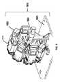
図2は、UAV201およびエネルギー供給ステーション202を備えるエネルギー供給システムの実施可能形態の詳細な図を示す。図2に示されるUAV201は、エネルギー供給システムの一部であり得るUAVの一例である。示されているUAVは、複数のローター203を有してよい。複数のローター203は、制御部、慣性測定部(IMU)、プロセッサ、バッテリー、電源、および/またはその他複数のセンサを備えてよいUAV204の本体に接続してよい。複数のローターは、本体の中央部から分岐してよい一または複数のアームまたは伸張部を介して本体に接続されてよい。例えば、一または複数のアームは、UAVの中央の本体から放射状に延びてよく、複数のアームの端部に、または端部近辺に、複数のローターを有してよい。 FIG. 2 shows a detailed view of an possible embodiment of an energy supply system comprising a
UAVは、着陸スタンド205によってエネルギー供給ステーションの表面に位置されてよい。着陸スタンドは、UAVが飛行中でない場合に、UAVの重量を支持するように構成されてよい。着陸スタンドは、UAVから延びてよい一または複数の延長部材を含んでよい。着陸スタンドの複数の延長部材は、UAVの一または複数のアームから、または、UAVの中央の本体から延びてよい。着陸スタンドの複数の延長部材は、一または複数のローターの下方から、または、一または複数のローターの近辺から延びてよい。複数の延長部材は、実質的に垂直に延びてよい。 The UAV may be located on the surface of the energy supply station by a
エネルギー供給ステーション202は、バッテリーステーションであってよい。エネルギー供給ステーションは、地上ステーションであってよい。エネルギー供給ステーションは、バッテリー交換ステーションまたはバッテリー取り換えステーションであってよい。エネルギー供給ステーションは、バッテリー再充電ステーションであってよい。エネルギー供給ステーションは、携帯可能であってよい。エネルギー供給ステーションは、人間によって運ばれることが可能であってよい。エネルギー供給ステーションは、人間によって片手で、または両手で持ち上げられることが可能であってよい。エネルギー供給ステーションは、より携帯性が上がるように、再構成可能であってよく、あるいは、折り畳まれてよい。 The
エネルギー供給ステーション202は、UAV用の離着陸区域206を有してよい。エネルギー供給ステーションのあらゆる表面は、離着陸区域を備えるように適合されてよい。例えば、エネルギー供給ステーションの上面が離着陸区域を形成してよい。必要に応じて、一または複数のプラットフォームが、UAV用の離着陸区域として備えられてよい。複数のプラットフォームは、任意の側面、天井、またはカバーを含んでもよいし、含まなくてもよい。 The
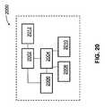
エネルギー供給ステーション202は、バッテリー格納システムをさらに備えてよい。バッテリー格納システムは、一または複数のバッテリーを格納するように構成されてよい。バッテリー格納システムは、格納される一または複数のバッテリーを充電してよい。図2に示される例においては、バッテリー格納システム207が、離着陸区域206の下方に示されている。エネルギー供給ステーションの別の構成部品は、UAVからバッテリーを取り外すように構成され、且つ、取り外されたバッテリーを、バッテリー格納システムからの完全にまたは部分的に充電されたバッテリーと交換するように構成された機構であってよい。 The
UAVの垂直位置および/または速度は、UAVの一または複数の推進ユニットへの出力を維持すること、および/または調節することによって制御されてよい。例えば、UAVの一または複数のローターの回転速度を上げることは、UAVに高度を上げさせる、またはより高速で高度を上げさせることを補助してよい。一または複数のローターの回転速度を上げることは、複数のローターの推進力を増大させてよい。UAVの一または複数のローターの回転速度を低下させることは、UAVに高度を下げさせる、またはより高速で高度を下げさせることを補助してよい。一または複数のローターの回転速度を低下させることは、一または複数のローターの推進力を低下させてよい。例えばエネルギー供給ステーションからUAVが離陸している場合、出力が複数の推進ユニットに供給されてよく、その前の着陸した状態から増大されてよい。例えば機体にUAVが着陸している場合、複数の推進ユニットに供給される出力は、その前の飛行状態から低下されてよい。UAVは、実質的に垂直な様式で、エネルギー供給ステーションから離陸するように、および/または、エネルギー供給ステーションに着陸するように構成されてよい。 The vertical position and / or speed of the UAV may be controlled by maintaining and / or adjusting the output to one or more propulsion units of the UAV. For example, increasing the rotational speed of one or more rotors of a UAV may help cause the UAV to increase altitude or to increase altitude at a higher speed. Increasing the rotational speed of the rotor or rotors may increase the propulsive force of the rotors. Decreasing the rotational speed of one or more rotors of the UAV may assist the UAV in reducing the altitude or lowering the altitude at a higher speed. Reducing the rotational speed of the one or more rotors may reduce the propulsive force of the one or more rotors. For example, if the UAV is taking off from an energy supply station, the output may be supplied to multiple propulsion units and increased from the previous landing state. For example, when a UAV has landed on the aircraft, the power supplied to the plurality of propulsion units may be reduced from the previous flight state. The UAV may be configured to take off from and / or land on the energy supply station in a substantially vertical manner.
UAVの横方向の位置および/または速度は、UAVの一または複数の推進ユニットへの出力を維持すること、および/または調節することにより制御されてよい。UAVの高度およびUAVの一または複数のローターの回転速度は、UAVの横方向の動きに影響を与え得る。例えばUAVは、特定の方向に動くためにその方向に傾けられてよく、UAVの複数のローターの速度は、横方向の動きの速度および/または動きの軌道に影響を与え得る。UAVの横方向の位置および/または速度は、UAVの一または複数のローターの回転速度を変更すること、または維持することによって制御されてよい。 The lateral position and / or speed of the UAV may be controlled by maintaining and / or adjusting the output to one or more propulsion units of the UAV. The altitude of the UAV and the rotational speed of one or more rotors of the UAV can affect the lateral movement of the UAV. For example, a UAV may be tilted in that direction to move in a particular direction, and the speed of multiple UAV rotors can affect the speed of lateral movement and / or the trajectory of movement. The lateral position and / or speed of the UAV may be controlled by changing or maintaining the rotational speed of one or more rotors of the UAV.
UAV101は、小さい寸法であってよい。UAVは、人間によって持ち上げられること、および/または運ばれることが可能であってよい。UAVは、人間によって片手で運ばれることが可能であってよい。エネルギー供給ステーションは、UAVが着陸するための空間を提供するように構成された離着陸区域を有してよい。UAVの寸法は、必要に応じて、エネルギー供給ステーション離着陸区域の幅を超えないようにしてよい。UAVの寸法は、必要に応じて、エネルギー供給ステーション離着陸区域の長さを超えないようにしてよい。 The
UAV101は、100cmを超えないような最大の寸法(例えば、長さ、幅、高さ、対角線、直径)を有してよい。場合によっては、最大の寸法は、1mm、5mm、1cm、3cm、5cm、10cm、12cm、15cm、20cm、25cm、30cm、35cm、40cm、45cm、50cm、55cm、60cm、65cm、70cm、75cm、80cm、85cm、90cm、95cm、100cm、110cm、120cm、130cm、140cm、150cm、160cm、170cm、180cm、190cm、200cm、220cm、250cm、または300cmよりも小さいか、あるいは等しくてよい。必要に応じて、UAVの最大の寸法は、本明細書中に記載されるあらゆる値よりも大きくてよい、または、等しくてよい。UAVは、本明細書中に記載される複数の値のうち、任意の2つの間の範囲に含まれる最大の寸法を有してよい。 The
UAV101は軽量であってよい。例えばUAVは、1mg、5mg、10mg、50mg、100mg、500mg、1g、2g、3g、5g、7g、10g、12g、15g、20g、25g、30g、35g、40g、45g、50g、60g、70g、80g、90g、100g、120g、150g、200g、250g、300g、350g、400g、450g、500g、600g、700g、800g、900g、1kg、1.1kg、1.2kg、1.3kg、1.4kg、1.5kg、1.7kg、2kg、2.2kg、2.5kg、3kg、3.5kg、4kg、4.5kg、5kg、5.5kg、6kg、6.5kg、7kg、7.5kg、8kg、8.5kg、9kg、9.5kg、10kg、11kg、12kg、13kg、14kg、15kg、17kg、または20kgよりも軽いか、あるいは等しくてよい。UAVは、本明細書中に記載されるあらゆる値よりも大きいかまたは等しい重量を有してよい。UAVは、本明細書中に記載される複数の値のうち、任意の2つの間の範囲に含まれる重量を有してよい。 The
UAVの一または複数の構成部品は、バッテリーによって電力を供給されてよい。例えば、UAV全体がバッテリーによって電力を供給されてよい。あるいは、推進ユニット、コントローラ、通信部、慣性測定部(IMU)、および/または、その他複数のセンサのみがバッテリーによって電力を供給されてよい。バッテリーとは、単一のバッテリー、または、2またはそれ以上のバッテリーのパックを指すことができる。バッテリーの一例は、リチウムイオンバッテリー、アルカリバッテリー、ニッケルカドミウムバッテリー、鉛酸バッテリー、または、ニッケル水素バッテリーを含んでよい。バッテリーは、使い捨て型または充電式バッテリーであってよい。バッテリーの寿命(すなわち、再充電が必要になる前に、UAVに対して電力を供給するであろう時間の量)は多様であってよい。寿命は、少なくとも1分、5分、10分、15分、30分、45分、1時間、2時間、3時間、4時間、5時間、または10時間であってよい。バッテリー寿命は、本明細書中に記載される任意の値よりも長いかまたは等しい継続時間を有してよい。バッテリー寿命は、本明細書中に記載される複数の値のうち、任意の2つの間の範囲に含まれる継続時間を有してよい。 One or more components of the UAV may be powered by a battery. For example, the entire UAV may be powered by a battery. Alternatively, only the propulsion unit, controller, communication unit, inertial measurement unit (IMU), and / or a plurality of other sensors may be powered by the battery. A battery can refer to a single battery or a pack of two or more batteries. An example of the battery may include a lithium ion battery, an alkaline battery, a nickel cadmium battery, a lead acid battery, or a nickel metal hydride battery. The battery may be a disposable or rechargeable battery. The lifetime of the battery (ie, the amount of time it will supply power to the UAV before recharging is required) may vary. The lifetime may be at least 1 minute, 5 minutes, 10 minutes, 15 minutes, 30 minutes, 45 minutes, 1 hour, 2 hours, 3 hours, 4 hours, 5 hours, or 10 hours. The battery life may have a duration that is longer than or equal to any value described herein. The battery life may have a duration that falls within a range between any two of the values described herein.
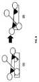
バッテリーは、電気接続によってUAVへと電力を供給するために、UAVに連結されてよい。バッテリーについての本明細書中の説明はいずれも、一または複数のバッテリーに対して適用してよい。バッテリーについての説明はいずれもバッテリーパックに対して適用してよい。あるいは、その逆のことも言える。ここでバッテリーパックは、一または複数のバッテリーを含んでよい。複数のバッテリーは、直列に、並列に、または、それらの任意の組み合わせで接続されてよい。UAVとバッテリーとの間、または、UAVの構成部品とバッテリーとの間で、電気接続が提供されてよい。バッテリーの電気接点は、UAVの電気接点と接触してよい。UAVは、バッテリーを収容するための窪み領域を、その本体に有してよい。図3は、バッテリー303を収容するように構成された窪み領域302を、UAVの本体304に有するUAV301の一例を示す。窪み領域は、長さ、幅、および深さが等しくてよく、あるいは、等しくなくてもよい。窪み領域の長さ、幅、および深さの可能な値は、少なくとも1mm、5mm、1cm、3cm、5cm、10cm、12cm、15cm、20cm、25cm、30cm、35cm、40cm、45cm、50cm、55cm、60cm、65cm、70cm、75cm、80cm、85cm、90cm、95cm、または100cmであってよい。窪み領域は、一または複数のバッテリーを保持するように構成されてよい。窪み領域は、UAV電力システムへとバッテリーを接続するための複数の電気接点を含んでよい。さらに、窪み領域は、バッテリーに残っている充電量を動的に読み取り、記録し得るセンサと通信するための複数の電気接続を備えてよい。窪み領域は、UAVに搭載されているバッテリーと電気的に接触してよい一または複数の電気接点を含んでよい。複数の電気接点は、バッテリーが窪み領域内にある間にバッテリーに連結されてよく、バッテリーが取り外された場合には、接点はバッテリーから接続が切られてよい。 The battery may be coupled to the UAV to provide power to the UAV through an electrical connection. Any description herein for a battery may apply to one or more batteries. Any description of the battery may be applied to the battery pack. Or vice versa. Here, the battery pack may include one or more batteries. The plurality of batteries may be connected in series, in parallel, or any combination thereof. An electrical connection may be provided between the UAV and the battery or between the UAV component and the battery. The battery electrical contacts may contact the UAV electrical contacts. The UAV may have a recessed area in its body for accommodating the battery. FIG. 3 illustrates an example of a
エネルギー供給ステーションによってUAVのバッテリーを入れ換える方法は、エネルギー供給ステーションにUAVを着陸させること、エネルギー供給ステーションの構成部品を用いて、搭載されたバッテリーをUAVから取り外すこと、搭載されたバッテリーをエネルギー供給ステーションに備えられた別のバッテリーと交換すること、別のバッテリーをUAVに連結すること、および、UAVをエネルギー供給ステーションから離陸させること、の複数の段階を含んでよい。これらの段階の全てまたは任意の1つは、完全に、あるいは、部分的に自動化されてよい。 The method of replacing the UAV battery by the energy supply station is to land the UAV on the energy supply station, remove the mounted battery from the UAV using the components of the energy supply station, and remove the mounted battery from the energy supply station. Multiple steps may be included: exchanging with another battery provided to the UAV, coupling another battery to the UAV, and taking the UAV off the energy supply station. All or any one of these steps may be fully or partially automated.
バッテリー交換の方法の一例が、図4のフローチャートに示されている。図4に記載される複数の段階は、示されている順序に行われてよいし、あるいは、複数の段階が順序に関係なく行われてよい。バッテリー交換の方法は、列挙される複数の段階の全て、または、列挙される複数の段階のサブセットを含んでよい。最初にUAVは、エネルギー供給ステーションの離着陸区域に着陸してよい:401。UAVが着陸した後、エネルギー供給ステーションの機構によって、消耗したバッテリーが取り外されてよい。エネルギー供給ステーションは、消耗したバッテリーをUAVから取り外すためにロボットアームを使用してよい:402。消耗したバッテリーは、取り外されると、バッテリー格納ユニットに格納されてよい。バッテリー格納ユニットは、バッテリー用の容器を備えてよい。容器は、バッテリーに充電を供給するように構成された複数の電気接続を含んでよい。バッテリー格納区域の一例は、エネルギー供給ステーションに搭載された回転式搬送機であってよい:403。消耗したバッテリーを運び去るため、および、充電されたバッテリーをUAVにインストールするように構成された機構と一致するように充電されたバッテリーを配置するために回転し得るように、回転式搬送機が構成されてよい。いくつかの例においては、そのような機構は、ロボットアームであってよい:404。充電されたバッテリーをUAVへと運ぶロボットアームは、消耗したバッテリーをUAVから取り外すロボットアームと同一のものであってよい。回転式搬送機の回転後、ロボットアームは、充電されたバッテリーをUAVにインストールしてよい:405。最後の段階は、完全に充電されたバッテリーが搭載された状態で、離着陸区域からUAVを離陸させるためのものであってよい:406。 An example of a battery replacement method is shown in the flowchart of FIG. The steps described in FIG. 4 may be performed in the order shown, or the steps may be performed regardless of the order. The battery replacement method may include all of the listed stages or a subset of the listed stages. Initially, the UAV may land in the takeoff / landing area of the energy supply station: 401. After the UAV has landed, the depleted battery may be removed by the energy supply station mechanism. The energy supply station may use a robotic arm to remove the depleted battery from the UAV: 402. When the depleted battery is removed, it may be stored in a battery storage unit. The battery storage unit may comprise a battery container. The container may include a plurality of electrical connections configured to supply charge to the battery. An example of a battery storage area may be a rotary transporter mounted on an energy supply station: 403. The rotary transporter can be rotated to carry away the depleted battery and to place the charged battery to match the mechanism configured to install the charged battery in the UAV May be configured. In some examples, such a mechanism may be a robotic arm: 404. The robot arm that carries the charged battery to the UAV may be the same robot arm that removes the depleted battery from the UAV. After rotation of the rotary transporter, the robot arm may install a charged battery in the UAV: 405. The last step may be to take off the UAV from the takeoff / landing area with a fully charged battery installed: 406.
UAVは、エネルギー供給ステーションと通信してよい。例えばUAVは、UAVに搭載されたバッテリーの状態、現在の飛行条件、現在のミッションにおける残りの時間または距離、次のエネルギー供給ステーションまでの距離、バッテリーの仕様、バッテリー充電の状態(例えば、残りの電力の推定値)、バッテリー温度、UAVの仕様、または飛行計画(例えば、到着が推定される次のエネルギー供給ステーションおよび/または最終目的地への推定される到着時間)についての情報を、エネルギー供給ステーションに送信してよい。UAVは、UAVの状態を説明する情報をエネルギー供給ステーションへ通信してもよい。例えばUAVは、システムの故障を説明する情報または損傷した部品(例えば、壊れたプロペラ)の説明を、エネルギー供給ステーションへ通信してよい。UAVは、積載物を運んでよい。UAVは、積載物の重量を通信してよい。さらにUAVは、UAVが飛行計画中のいつ積載物を積み込むこと、または降ろすことを計画しているのかを、エネルギー供給ステーションへ通信してよい。 The UAV may communicate with an energy supply station. For example, the UAV may indicate the status of the battery installed in the UAV, the current flight conditions, the remaining time or distance in the current mission, the distance to the next energy supply station, the battery specifications, the status of the battery charge (eg, remaining battery Information about power estimates), battery temperature, UAV specifications, or flight plans (eg, estimated next arrival time and / or estimated arrival time to final destination), energy supply May be sent to station. The UAV may communicate information describing the state of the UAV to the energy supply station. For example, the UAV may communicate information describing a system failure or a description of a damaged part (eg, a broken propeller) to the energy supply station. The UAV may carry loads. The UAV may communicate the weight of the load. In addition, the UAV may communicate to the energy supply station when the UAV is planning to load or unload the load during the flight plan.
UAVからの情報に応じて、または、UAVからの通信とは独立して、エネルギー供給ステーションは、UAVへと情報を通信してよい。エネルギー供給ステーションは、充電されたバッテリーをUAVに提供するのに利用可能か否かに関し、UAVに情報を伝えてよい。例えば、エネルギー供給ステーションが充電されたバッテリーを使い切っていたり、あるいは、別のUAVによってエネルギー供給ステーションが占有されていたりすることがあり得る。このような場合、エネルギー供給ステーションは、次に最も近いエネルギー供給ステーションへと進み続けるようにUAVに指示してよい。別の場合には、エネルギー供給ステーションは、悪天候条件(例えば、風、雨、雪)の場合に、あるいはエネルギー供給ステーションの機械的または電気的な故障の場合に、次に最も近いエネルギー供給ステーションへと進み続けるようにUAVに指示してよい。エネルギー供給ステーションは、次のエネルギー供給ステーションへとUAVを向かわせるために、アップデートされたルートの指示をUAVに送信してよい。あるいは、充電用にエネルギー供給ステーションが利用可能な場合には、エネルギー供給ステーションは、ステーションに着陸するようにUAVに指示してよい。 In response to information from the UAV or independent of communication from the UAV, the energy supply station may communicate information to the UAV. The energy supply station may communicate information to the UAV as to whether a charged battery is available to provide to the UAV. For example, the energy supply station may have used up the charged battery, or the energy supply station may be occupied by another UAV. In such a case, the energy supply station may instruct the UAV to continue to the next closest energy supply station. In other cases, the energy supply station is the next closest energy supply station in case of bad weather conditions (eg wind, rain, snow) or in the case of mechanical or electrical failure of the energy supply station. The UAV may be instructed to continue. The energy supply station may send an updated route indication to the UAV to direct the UAV to the next energy supply station. Alternatively, if an energy supply station is available for charging, the energy supply station may instruct the UAV to land on the station.
低バッテリー充電の場合、UAVは、エネルギー供給ステーションに着陸するように指示されてよい。エネルギー供給に着陸させるための指示が、エネルギー供給ステーションによって送信されてよい。バッテリーの充電が低過ぎて、UAVの現在のミッションまたはUAVの飛行計画におけるUAVの残りの時間または距離を満たすことがUAVには可能でない場合、UAVは、エネルギー供給ステーションに着陸するように指示されてよい。エネルギー消費の予測される速さ、または、エネルギー消費の現在の速さのような複数のUAV動作パラメータが考慮されてよい。例えば、複数のセンサのうち1または複数が動作していないような比較的"低電力"のモードでUAVが飛んでいるかもしれないが、その後の飛行においてこのUAVは、より多くのセンサを使用するかもしれないことが予測されることがあり得る。予測されるエネルギー消費の増大した速度は、予測されるバッテリー充電消耗の速度に影響を与え得る。これは、UAVがエネルギー供給ステーションに着陸する必要があるかどうかを決定する際に考慮されてよい。バッテリーの充電状態が予め定められた閾値を下回る場合、必要に応じてUAVは、エネルギー供給ステーションに着陸するように指示されてよい。さらに、UAVに搭載された機械的または電気的システムに修理の必要がある場合(例えば、壊れたプロペラ、電気部品のショート)、UAVはエネルギー供給ステーションに着陸するように指示されてよい。 In the case of a low battery charge, the UAV may be instructed to land at the energy supply station. Instructions for landing on the energy supply may be sent by the energy supply station. If the battery is too low to allow the UAV to meet the remaining time or distance of the UAV in the UAV's current mission or UAV flight plan, the UAV is instructed to land at the energy supply station It's okay. A plurality of UAV operating parameters may be considered, such as the expected speed of energy consumption or the current speed of energy consumption. For example, a UAV may be flying in a relatively "low power" mode where one or more of the sensors is not operating, but this UAV will use more sensors in subsequent flights. It may be predicted that it may do. The increased rate of predicted energy consumption can affect the predicted rate of battery charge drain. This may be taken into account when determining whether the UAV needs to land at the energy supply station. If the state of charge of the battery is below a predetermined threshold, the UAV may be instructed to land at the energy supply station if necessary. Further, if a mechanical or electrical system mounted on the UAV needs repair (eg, broken propeller, electrical component short), the UAV may be instructed to land at the energy supply station.
エネルギー供給ステーションに着陸することは、UAVの飛行計画によって予め定められていてよい。例えば、地点Aから地点Bまで移動するように指示されたUAVは、地点Aと地点Bとの間の中間のエネルギー供給ステーションにおける計画された休止を有してよい。飛行計画の一部としてエネルギー供給ステーションに着陸することの決定は、占有されていないエネルギー供給ステーション次第であってよい。例えば、地点Aと地点Bとの間の中間のエネルギー供給ステーションが別のUAVによって占有されているとすると、バッテリーに残っている電力が、次のエネルギー供給ステーションに到達するのに十分なものである限り、UAVは、次のエネルギー供給ステーションへと進み続けるようにその飛行計画を変更してよい。 Landing at the energy supply station may be predetermined by the UAV flight plan. For example, a UAV instructed to move from point A to point B may have a planned outage at an intermediate energy supply station between point A and point B. The decision to land on the energy supply station as part of the flight plan may depend on the unoccupied energy supply station. For example, if an intermediate energy supply station between point A and point B is occupied by another UAV, the power remaining in the battery is sufficient to reach the next energy supply station. As long as it is, the UAV may change its flight plan to continue to the next energy supply station.
1よりも多くのUAVが、エネルギー供給ステーションに着陸する目的でエネルギー供給ステーションを特定する場合、複数のUAVが順番待ち状態に入れられてよい。順番待ち状態の複数のUAVは、エネルギー供給ステーションへのアクセスを待ってよい。順番待ち状態の複数のUAVは、エネルギー供給ステーションからの緊急の補助が必要なUAV(例えば、機械的な故障および/または危機的な低バッテリーにあるもの)が、エネルギー供給ステーションからの補助の必要性がより低いUAVの前に並ぶことができるように、順番が付けられてよい。順番待ち状態の複数のUAVは、複数の層によってランク付けされてよく、あるいは、様々な要因の評価システムに基づいてランク付けされてよい。複数の層によるランク付けの場合、第1の層は、UAVの機械的または電気的状態であってよく、第2の層は、UAVのバッテリーに残っているエネルギーであってよく、第3の層は、エネルギー供給ステーションからの補助をどれだけ長い間UAVが待っているかであってよい。複数の層は、順番待ち状態の複数のUAVのランク付けに使用されてよい。あるいは、評価システムにおいて、UAVの複数の構成部品の機械的または電気的状態、UAVのバッテリーに残っている電力貯蔵、および、どれだけ長い間UAVが順番待ち状態で待っているかのような複数の要因が考慮されてよい。上記の複数の要因の加重平均(例えばスコア)が、順番待ち状態の複数のUAVの位置を決定するために使用されてよい。 If more than one UAV identifies an energy supply station for the purpose of landing on the energy supply station, multiple UAVs may be queued. A plurality of UAVs in the waiting state may wait for access to the energy supply station. Multiple UAVs in queue are in need of emergency assistance from the energy supply station (for example, mechanical failure and / or in a critically low battery) but need assistance from the energy supply station It may be ordered so that it can be lined up in front of a less powerful UAV. A plurality of UAVs in queue may be ranked by multiple layers, or may be ranked based on various factor evaluation systems. For ranking by multiple layers, the first layer may be the mechanical or electrical state of the UAV, the second layer may be the energy remaining in the UAV battery, and the third layer The stratum may be how long the UAV has been waiting for assistance from the energy supply station. Multiple layers may be used to rank multiple UAVs in queue. Alternatively, in the evaluation system, a plurality of UAV components such as mechanical or electrical status, power storage remaining in the UAV battery, and how long the UAV has been waiting in turn Factors may be considered. A weighted average (eg, score) of the above multiple factors may be used to determine the location of multiple UAVs waiting for turn.
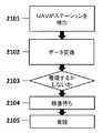
UAVとエネルギー供給ステーションとの間の相互作用は、図21の手順の概要に従ってよい。この相互作用は、図21に示される全ての段階を含んでよいし、あるいは、これらの複数の段階のサブセットを含んでよい。これら複数の段階は、示されている順序で、あるいは入れ替わった順序で行われてよい。まず、UAVは、エネルギー供給ステーションを検出してよい:2101。UAVによるエネルギー供給ステーションの検出は、エネルギー供給ステーションの位置を示す既知のGPS信号に応答したもの、視覚検出、または音声検出であってよい。UAVはエネルギー供給ステーションと情報を交換してよい:2102。例えばUAVは、UAVおよび/またはバッテリーの状態に関する情報を通信してよい。エネルギー供給ステーションは、エネルギー供給ステーションの状態に関する情報をUAVに提供してよい。情報交換に基づいて、UAVは、そのエネルギー供給ステーションに着陸するべきか、または、自身の飛行経路を続けるべきかどうかを決定してよい:2103。もしもUAVがそのエネルギー供給ステーションに着陸することを決定した場合、そのエネルギー供給ステーションに着陸するために待機している複数のUAVの順番待ち状態に入ってよい:2104。このUAVが順番待ち状態の1番目のUAVであり、エネルギー供給ステーションが別のUAVによって占有されていない場合、UAVはエネルギー供給ステーションに着陸してよい:2105。 The interaction between the UAV and the energy supply station may follow the outline of the procedure of FIG. This interaction may include all the stages shown in FIG. 21 or may include a subset of these multiple stages. These multiple steps may be performed in the order shown or in an interchanged order. First, the UAV may detect an energy supply station: 2101. The detection of the energy supply station by the UAV may be in response to a known GPS signal indicating the position of the energy supply station, visual detection or audio detection. The UAV may exchange information with the energy supply station: 2102. For example, the UAV may communicate information regarding the UAV and / or battery status. The energy supply station may provide information about the state of the energy supply station to the UAV. Based on the information exchange, the UAV may decide whether to land on its energy supply station or continue its flight path: 2103. If the UAV decides to land at that energy supply station, it may enter a waiting state for multiple UAVs waiting to land at that energy supply station: 2104. If this UAV is the first UAV in queue and the energy supply station is not occupied by another UAV, the UAV may land on the energy supply station: 2105.
UAVは、マークを感知することによってエネルギー供給ステーション離着陸区域を識別してよい。例えばマークは、エネルギー供給ステーション離着陸区域に見ることができる、浮き出しパターン、窪みパターン、イメージ、シンボル、デカール、1−D、2−D、または3−Dバーコード、QRコード(登録商標)、あるいは、複数の光であってよい。マークは、エネルギー供給ステーションが、利用可能な複数の充電されたバッテリーを有していることを示してよい。例えばマークは、光または複数の光のパターンであってよい。複数の光は、エネルギー供給ステーションが、利用可能な複数の充電されたバッテリーを有している場合にのみ、オンにされてよい。 The UAV may identify the energy supply station takeoff and landing area by sensing the mark. For example, the mark can be seen in an energy supply station takeoff / landing area, raised pattern, recessed pattern, image, symbol, decal, 1-D, 2-D, or 3-D barcode, QR code, or May be a plurality of lights. The mark may indicate that the energy supply station has a plurality of charged batteries available. For example, the mark may be a light or multiple light pattern. The multiple lights may be turned on only if the energy supply station has multiple charged batteries available.
UAVは、エネルギー供給ステーション離着陸区域に対して垂直に離陸および着陸してよい。離着陸区域は、着陸する間にUAVを誘導するための、複数の窪んだ嵌合機構を備えてよい。複数の嵌合機構は、離着陸区域にUAVを着陸させる場合に、精度に対する要求を低減させてよい。複数の窪んだ機構は、多種多様なUAVと嵌合するように構成されてよい。あるいは複数の嵌合機構は、ある単一のUAV製造業者、単一のUAV機体、または1台の特定のUAVに対して特異的なものであってよい。 The UAV may take off and land perpendicular to the energy supply station takeoff and landing area. The takeoff / landing area may include a plurality of recessed mating mechanisms for guiding the UAV during landing. Multiple mating mechanisms may reduce accuracy requirements when landing UAVs in takeoff and landing areas. The plurality of recessed features may be configured to mate with a wide variety of UAVs. Alternatively, multiple mating mechanisms may be specific to a single UAV manufacturer, a single UAV airframe, or a specific UAV.
UAVとエネルギー供給ステーションとの間の通信は、エネルギー供給ステーションの大体の位置へとUAVを到着させるために使用されてよい。UAVとエネルギー供給ステーションとの間の通信は、無線で行われてよい。UAVは、エネルギー供給ステーションの位置を特定するために、GPSまたはその他の位置特定ソフトウェアを使用してよい。GPSまたはその他の位置探知技術は、UAVをエネルギー供給ステーションの近傍に到着させるために使用されることができる。無線通信は、複数のエネルギー供給ステーションの一または複数の部分を感知するための範囲内にUAVを到着させてよい。例えばUAVは、エネルギー供給ステーションの照準線へともたらされてよい。離着陸区域マーカまたは複数のマーカは、エネルギー供給ステーションの位置をさらに正確に示すことを補助しよてい。マーカは、UAVが着陸してよいエネルギー供給ステーションの確認の役割を果たしてよい。複数のマーカは、その他複数の物体や領域から、エネルギー供給ステーションまたはエネルギー供給ステーションの離着陸区域を識別させてもよい。 Communication between the UAV and the energy supply station may be used to reach the UAV to the approximate location of the energy supply station. Communication between the UAV and the energy supply station may be performed wirelessly. The UAV may use GPS or other location software to locate the energy supply station. GPS or other location techniques can be used to bring the UAV near the energy supply station. The wireless communication may cause the UAV to arrive within range for sensing one or more portions of the plurality of energy supply stations. For example, the UAV may be brought to the line of sight of the energy supply station. The take-off and landing area marker or markers may help to more accurately indicate the location of the energy supply station. The marker may serve as a confirmation of the energy supply station where the UAV may land. The plurality of markers may identify the energy supply station or the takeoff and landing area of the energy supply station from a plurality of other objects and regions.
マーカは、エネルギー供給ステーションにおけるUAVの着陸位置を示すために有用であってよい。マーカは、基準マーカとして使用されてよく、これは、エネルギー供給ステーションにおける適切な着陸位置へとナビゲートすることにおいてUAVを補助してよい。いくつかの例においては、複数のマーカが備えられてよく、所望の位置へのUAVの着陸を補助してよい。場合によっては、エネルギー供給ステーションとドッキングする場合に、UAVが特定の方向性を有することが望ましい場合もある。一例においてマーカは、UAVによって識別できるであろう非対称なイメージまたはコードを含んでよい。基準は、UAVに対するエネルギー供給ステーションの方向を指示するものであってよい。従って、UAVは、エネルギー供給ステーションに着陸する場合に、自身を適切に方向付けることが可能であるだろう。マーカは、UAVに対するエネルギー供給ステーションの距離を指示するものであってもよい。これは、UAVの高度を決定するために、UAVのその他の一または複数のセンサとは別個に、またはこれらと組み合わせて使用されてよい。例えば、もしも基準マーカのサイズが既知であれば、UAVからマーカまでの距離が、UAVの複数のセンサ中に現れるマーカのサイズに応じて測定されてよい。 The marker may be useful for indicating the landing position of the UAV at the energy supply station. The marker may be used as a reference marker, which may assist the UAV in navigating to the appropriate landing position at the energy supply station. In some examples, multiple markers may be provided and may assist in landing the UAV at a desired location. In some cases, it may be desirable for the UAV to have a specific orientation when docking with an energy supply station. In one example, the marker may include an asymmetric image or code that could be identified by the UAV. The reference may indicate the direction of the energy supply station relative to the UAV. Thus, a UAV will be able to properly orient itself when landing at an energy supply station. The marker may indicate the distance of the energy supply station relative to the UAV. This may be used separately from or in combination with one or more other UAV sensors to determine the UAV altitude. For example, if the size of the reference marker is known, the distance from the UAV to the marker may be measured according to the size of the marker appearing in a plurality of UAV sensors.
一例においてマーカは、エネルギー供給ステーションにおけるUAVの所望の着陸スポットに対して特定の位置に備えられてよい。これは、エネルギー供給ステーションの離着陸区域における所望の着陸スポットに対して特定の位置にあってよい。UAVは、良好な精度で離着陸区域に着陸することが可能であってよい。マーカは、正確な所望のスポットへとUAVを誘導することを支援してよい。例えばマーカは、UAVの所望の着陸地点の中心の10cm手前に配置されてよい。UAVは、正確な着陸スポットへとUAVを誘導するためにマーカを使用してよい。いくつかの例においては、複数のマーカが備えられてよい。所望の着陸スポットは、複数のマーカの間に入ってよい。UAVは、UAVを方向付けること、および/または、複数のマーカの間にその着陸を位置合わせすることを支援するために、複数のマーカを使用してよい。複数のマーカ間の距離は、離着陸区域までのUAVの距離を測定することにおいてUAVを補助してよい。 In one example, the marker may be provided at a specific location relative to the desired landing spot of the UAV at the energy supply station. This may be at a specific location relative to the desired landing spot in the takeoff and landing area of the energy supply station. The UAV may be able to land in the takeoff and landing area with good accuracy. The marker may help guide the UAV to the exact desired spot. For example, the marker may be placed 10 cm before the center of the desired landing point of the UAV. The UAV may use markers to guide the UAV to the correct landing spot. In some examples, multiple markers may be provided. The desired landing spot may fall between a plurality of markers. A UAV may use multiple markers to help direct the UAV and / or align its landing between multiple markers. The distance between the markers may assist the UAV in measuring the distance of the UAV to the takeoff / landing area.
マーカは、エネルギー供給ステーションまたは離着陸区域のどこに備えられてもよい。マーカは、上方から容易に認識されるような位置に配置されてよい。場合によっては、マーカはエネルギー供給ステーションの外面に備えられてよい。マーカは、エネルギー供給ステーションによって発せられる無線信号を含んでよい。信号の発信源は、エネルギー供給ステーションの外側からでもよいし、あるいは、エネルギー供給ステーションの内側からでもよい。あるいは、エネルギー供給ステーションは、IRおよび/またはUV光、無線、または複数の音声信号を放射してよい。 The marker may be provided anywhere in the energy supply station or take-off and landing area. The marker may be arranged at a position where it can be easily recognized from above. In some cases, markers may be provided on the outer surface of the energy supply station. The marker may include a radio signal emitted by the energy supply station. The signal source may be from the outside of the energy supply station or from the inside of the energy supply station. Alternatively, the energy supply station may emit IR and / or UV light, radio, or multiple audio signals.
マーカは、UAVがエネルギー供給ステーションとドッキングするであろうところの近辺に配置されてよい。一例においてマーカは、UAVがエネルギー供給ステーションに着陸するところから、およそ、100cm、90cm、80cm、75cm、70cm、65cm、60cm、55cm、50cm、45cm、40cm、35cm、30cm、25cm、20cm、15cm、12cm、10cm、8cm、7cm、6cm、5cm、4cm、3cm、2cm、または1cmよりも近くに配置されてよい。 The marker may be located near where the UAV will dock with the energy supply station. In one example, the markers are approximately 100 cm, 90 cm, 80 cm, 75 cm, 70 cm, 65 cm, 60 cm, 55 cm, 50 cm, 45 cm, 40 cm, 35 cm, 30 cm, 25 cm, 20 cm, 15 cm, from where the UAV lands on the energy supply station. It may be located closer than 12 cm, 10 cm, 8 cm, 7 cm, 6 cm, 5 cm, 4 cm, 3 cm, 2 cm, or 1 cm.
検出されるマーカに関係するデータが、一または複数のプロセッサへと供給されてよい。複数のプロセッサは、UAVに搭載されたものであってよい。検出されたマーカについての検出された情報に基づいて、複数のプロセッサは、個々にまたは集合的に、命令信号を生成してよい。命令信号は、UAVの複数の推進ユニットを駆動してよい。例えば、検出されたマーカがエネルギー供給ステーションに属することが決定された場合、複数の推進ユニットは、検出されたマーカを有するこのエネルギー供給ステーションにUAVを着陸させるために駆動されてよい。検出されたマーカは、エネルギー供給ステーションに格納される複数のバッテリーの充電の状態を示してよい。例えば、利用可能で完全に充電されたバッテリーをエネルギー供給ステーションが有している場合、検出されたマーカは、UAVを着陸させるためのプロセッサからの命令となってよい。別の例においては、利用可能な充電されたバッテリーをエネルギー供給ステーションが有していない場合、検出されたマーカは、次のエネルギー供給ステーションへと進み続けるためのプロセッサからの命令となってよい。従ってUAVは、検出されたマーカに応じて、自律的または半自律的態様で着陸することが可能であってよい。UAVは、ユーザからの命令または手動入力を一切受信すること無しに着陸することが可能であってよい。 Data relating to the detected marker may be provided to one or more processors. The plurality of processors may be mounted on the UAV. Based on the detected information about the detected marker, the plurality of processors may generate command signals individually or collectively. The command signal may drive a plurality of propulsion units of the UAV. For example, if it is determined that the detected marker belongs to an energy supply station, the plurality of propulsion units may be driven to land the UAV on this energy supply station having the detected marker. The detected marker may indicate the state of charge of a plurality of batteries stored in the energy supply station. For example, if the energy supply station has an available and fully charged battery, the detected marker may be an instruction from the processor to land the UAV. In another example, if the energy supply station does not have an available charged battery, the detected marker may be an instruction from the processor to continue to the next energy supply station. Thus, the UAV may be able to land in an autonomous or semi-autonomous manner depending on the detected marker. The UAV may be able to land without receiving any command or manual input from the user.
いくつかの実施形態において、UAVに搭載された複数のセンサがマーカを検出するために使用されてよく、処理はUAVに搭載された状態で行われてよい。マーカがエネルギー供給ステーションに属することをUAVがひとたび確認すれば、UAVは、エネルギー供給ステーションからのさらなる誘導または情報を必要とせずに、エネルギー供給ステーションに自身を着陸させることが可能であってよい。 In some embodiments, multiple sensors mounted on the UAV may be used to detect the marker, and processing may be performed while mounted on the UAV. Once the UAV confirms that the marker belongs to the energy supply station, the UAV may be able to land itself at the energy supply station without requiring further guidance or information from the energy supply station.
エネルギー供給ステーションは、マーカ、および、一または複数の連結接続部品を含んでよい。エネルギー供給ステーションは、その位置についての情報をUAVへと送ってよい。エネルギー供給ステーションは、位置情報を決定することが可能な位置決め部を有してよい。エネルギー供給ステーションは、UAVの位置およびUAVに搭載されたバッテリーの状態についての情報をUAVから受信してよい。例えば、GPS座標のようなUAVに対する座標情報が、エネルギー供給ステーションへと提供されてよい。別の例においては、UAVは、現在UAVで使用中のバッテリーの残りの充電率を通信してよい。エネルギー供給ステーションは、UAVと通信することが可能な通信部を有してよい。エネルギー供給ステーションは、UAVの位置を識別するおよび/または算出することが可能なプロセッサを有してよい。さらに、エネルギー供給ステーションは、次に近いバッテリー取り換えステーションの位置を識別する、および/または算出することが可能なプロセッサを有してよい。例えばUAVは、エネルギー供給ステーションに対して、現在UAVに搭載されたバッテリーが残りの充電率18%を有することを通信してよい。エネルギー供給ステーションのプロセッサは、再充電するためにUAVが休止するべきか、あるいは、次のエネルギー供給ステーションまで続けるべきかを決定するために、UAVの飛行経路における次のバッテリー取り換えステーションまでの距離を決定してよい。 The energy supply station may include a marker and one or more coupling connections. The energy supply station may send information about its location to the UAV. The energy supply station may have a positioning part capable of determining position information. The energy supply station may receive information from the UAV about the location of the UAV and the status of the battery installed in the UAV. For example, coordinate information for the UAV, such as GPS coordinates, may be provided to the energy supply station. In another example, the UAV may communicate the remaining charge rate of the battery currently in use by the UAV. The energy supply station may have a communication unit capable of communicating with the UAV. The energy supply station may have a processor capable of identifying and / or calculating the location of the UAV. Furthermore, the energy supply station may have a processor capable of identifying and / or calculating the location of the next closest battery replacement station. For example, the UAV may communicate to the energy supply station that the battery currently installed in the UAV has a remaining charge rate of 18%. The energy supply station processor determines the distance to the next battery replacement station in the UAV flight path to determine whether the UAV should pause to recharge or continue to the next energy supply station. You may decide.
図5は、エネルギー供給ステーションの実施可能形態を示す。エネルギー供給ステーションは、3つの基本的な構成部品である、バッテリー交換部材501、UAV離着陸区域502、およびバッテリー格納ユニット503を有してよい。バッテリー交換部材は、UAVからバッテリーを取り外ように、および/または、充電されたバッテリーをUAVに配置するように構成されてよいメカニカルアーム501であってよい。場合によっては、メカニカルアームは、UAVからバッテリーを取り外すこと、および、充電されたバッテリーをUAVに配置することの両者を行ってよい。あるいは、異なる複数の機械構成部品が、UAVからバッテリーを取り外し、充電されたバッテリーをUAVに配置するために使用されてよい。メカニカルアームは、少なくとも1、2、3、4、5または6自由度を有してよい。メカニカルアームは、自律的にまたは半自律的に動いてよい。 FIG. 5 shows an possible embodiment of the energy supply station. The energy supply station may have three basic components: a
UAV離着陸区域502は、接近しているUAVによって独自に認識されてよい複数のマーカを備えてよい。離着陸区域は、パッシブ着陸ガイド504を備えてよい。複数のパッシブ着陸ガイドが、最終載置位置へとUAVを誘導するために、着陸に際して、UAVの構成部品と相互作用するように構成されてよい。UAVは、パッシブ着陸ガイドに適合し、最終載置位置へと誘導されてよい着陸スタンドを含んでよい。UAVは、UAVが着陸してよい表面を含んでよい。UAVは、表面で停止してよい。あるいは、UAVの重量の全てまたは大部分が、複数のパッシブ着陸ガイドによって支えられてよい。 The UAV take-off and
バッテリー格納ユニット503は、複数のバッテリーを格納してよい。バッテリー格納ユニットは、格納すると同時に、格納された複数のバッテリーを充電してよい。バッテリー格納ユニットは、複数のバッテリーを互いに対して動かしてよい。バッテリー格納ユニットは、UAV離着陸区域および/または離着陸区域にあるUAVに対して、複数のバッテリーを動かしてよい。複数のバッテリーは、バッテリー格納ユニットを用いて同時に移動されてよい。エネルギー供給ステーションにUAVが着陸する場合、完全に充電されたバッテリーは、メカニカルアーム501がバッテリーをUAVにインストールできるような位置にあってよい。例えばメカニカルアームは、UAVから、バッテリー格納ユニットに対する特定の位置へ、消耗したバッテリーを持って行ってよい。バッテリー格納ユニットは、消耗したバッテリーを受け入れてよい。バッテリー格納ユニットは、異なるバッテリー(例えば、完全に充電されたバッテリー)が、消耗したバッテリーが受け入れられた位置へ移動されるように、複数のバッテリーを移動させてよい。メカニカルアームは異なるバッテリーを受け取ってよい。場合によっては、その動きは、軸周りのバッテリー格納ユニットの回転を含んでよい。 The
エネルギー供給ステーションのUAV離着陸区域は、パッシブ着陸ガイドを備えるように構成されてよい。UAVは少なくとも1つの突出構造を有してよく、これは、エネルギー供給ステーションの離着陸区域における対応する空洞と嵌合してよい。例えば、UAVは4つの丸い円錐形のストッパーを有してよく、これらは、離着陸区域における4つの丸い円錐形のへこみの内部と適合してよい。突出構造はUAVの重量を支えるように構成された発射スタンドであってよい。図6は、複数の円錐形のストッパー603が離着陸区域の複数の円錐形のへこみ604と嵌合するように、UAV601がエネルギー供給ステーション602に着陸しようとしている一例を示す。代替的な実施形態において、ストッパーおよびへこみは、その他の様々な嵌合する形状を備えてよい。ストッパーはゴム、プラスチック、金属、木、または複合材料からできていてよい。ストッパーは、1mm、5mm、1cm、3cm、5cm、10cm、12cm、15cm、20cm、25cm、30cm、35cm、40cm、45cm、50cm、55cm、60cm、65cm、70cm、75cm、80cm、85cm、90cm、95cm、または100cmよりも小さいか、これらに等しい高さおよび幅を有してよい。複数のへこみは、これらがストッパーに合うべく適合されるような、対応する寸法を有してよい。 The UAV take-off and landing area of the energy supply station may be configured with a passive landing guide. The UAV may have at least one protruding structure, which may mate with a corresponding cavity in the takeoff and landing area of the energy supply station. For example, the UAV may have four round conical stoppers, which may fit within the four round conical dents in the takeoff and landing area. The protruding structure may be a launch stand configured to support the weight of the UAV. FIG. 6 shows an example where the
別の例においてUAVは、離着陸区域のへこみと完全には嵌合しない突起を備えてよい。この例においては、UAVは離着陸区域のへこみよりも小さくなるように設計され、UAVの底部から突出する構造を有してよい。UAVの底部の突出構造は、へこみに適合してよい。この構成の具体例においては、UAVが突出ロッドを有してよく、離着陸区域が円錐形のへこみを有してよい。着陸に際し、突出ロッドは、円錐形のへこみの底部に突き込まれてよい。例えば、もしも突出ロッドがへこみの側面にぶつかると、重力によって突出ロッドがへこみの底部まで滑らされるだろう。図7は、UAV702がドッキングされた離着陸区域701の実施可能形態の詳細な側面(左)および上面(右)図を示し、円錐形のへこみ703の内部に突出ロッドが適合している様子を示している。必要に応じて、突出ロッドは、UAVの着陸スタンドであってよい。UAVが離着陸区域にいる間に、複数の突出ロッドがUAVの重量を支えてよい。UAVが離着陸区域にいる間に、複数のへこみが複数の突出ロッドおよび/またはUAVの重量を支えてよい。 In another example, the UAV may include a protrusion that does not fully mate with a recess in the takeoff / landing area. In this example, the UAV may be designed to be smaller than the dent in the takeoff and landing area and may have a structure that protrudes from the bottom of the UAV. The protruding structure at the bottom of the UAV may be adapted to the dent. In an embodiment of this configuration, the UAV may have a protruding rod and the takeoff / landing area may have a conical recess. Upon landing, the protruding rod may be pushed into the bottom of the conical dent. For example, if the protruding rod hits the side of the dent, gravity will cause the protruding rod to slide to the bottom of the dent. FIG. 7 shows a detailed side (left) and top (right) view of an embodiment of the take-off and
パッシブ着陸ガイドは、UAV着陸手順における高精度制御の必要性を低減してよい。パッシブ着陸ガイドは、もしも所望の着陸位置からUAVがずれているような状態でステーションに接近する場合に、UAVが補正されるように構成されてよい。パッシブ着陸ガイドは、重力を用いて、UAVを所望の位置へと移動させてよい。図8は、UAVがずれて着陸位置に接近する場合に、パッシブ着陸ガイドがどのようにしてUAVを補正してよいかの一例を示す。図8に示される例においては、UAVは右へずれて着陸ガイドへと接近する(1)。UAVは部分的にパッシブ着陸ガイドと嵌合し、着陸ガイドと接触した後に、UAVは正しい位置へと下方向に滑ってよい(2)。正しい着陸位置へとUAVを補正するこの処理は、重力によるものであってよく、移動する部分または追加の機構の導入を必要としないであろう。 Passive landing guides may reduce the need for high precision control in UAV landing procedures. The passive landing guide may be configured to correct the UAV if it approaches the station if the UAV is offset from the desired landing position. The passive landing guide may use gravity to move the UAV to a desired position. FIG. 8 shows an example of how the passive landing guide may correct the UAV when the UAV deviates and approaches the landing position. In the example shown in FIG. 8, the UAV shifts to the right and approaches the landing guide (1). The UAV may partially mate with the passive landing guide, and after contacting the landing guide, the UAV may slide down to the correct position (2). This process of correcting the UAV to the correct landing position may be due to gravity and will not require the introduction of moving parts or additional mechanisms.
あるいはUAVは、動的干渉測位(RTK)を用いてエネルギー供給ステーションの位置を特定してよい。RTK位置特定方法は、UAVとエネルギー供給ステーションの両者が衛星信号、例えばGPS信号を放射する必要があるだろう。RTKは、10cm、9cm、8cm、7cm、6cm、5cm、4cm、3cm、2cm、1cm、または1cmよりも小さな精度内で、UAVが、エネルギー供給ステーションにおける正しいドッキング位置を特定することを可能にするであろう。 Alternatively, the UAV may use dynamic interference positioning (RTK) to locate the energy supply station. The RTK location method would require both the UAV and the energy supply station to emit satellite signals, eg GPS signals. The RTK allows the UAV to identify the correct docking location at the energy supply station within an accuracy of less than 10 cm, 9 cm, 8 cm, 7 cm, 6 cm, 5 cm, 4 cm, 3 cm, 2 cm, 1 cm, or 1 cm. Will.
エネルギー供給ステーションは、バッテリー格納システムを備えてよい。バッテリー格納システムは回転式搬送機であってよい。バッテリー格納システム中の複数のバッテリーは、完全に充電されているもの、部分的に充電されているもの、または充電を使い切っているものであってよい。複数のバッテリーは、消耗した状態または部分的に充電されている状態から、完全な充電状態までそれらを回復させるために、電力源に接続されてよい。複数のバッテリーは、サイズ、形状、およびバッテリーの種類(例えばリチウムイオン、ニッケルカドミウム)において同一であってよい。あるいは、異なるバッテリーサイズ、形状、または種類のものが収容されてよい。バッテリー格納システムは、少なくとも2、3、4、5、6、7、8、9、10、15、20、25、30、35、40、45または50個のバッテリーを格納するように構成されてよい。いくつかの実施形態においてバッテリーシステムは、記載されるバッテリーの数の任意のものよりも少ない数を格納してよい。バッテリーシステムは、記載される複数の値のうち、任意の2つの間の範囲内に含まれる数のバッテリーを格納してよい。 The energy supply station may comprise a battery storage system. The battery storage system may be a rotary transporter. The plurality of batteries in the battery storage system may be fully charged, partially charged, or fully charged. The plurality of batteries may be connected to a power source to restore them from a fully charged or partially charged state to a fully charged state. The plurality of batteries may be the same in size, shape, and type of battery (eg, lithium ion, nickel cadmium). Alternatively, different battery sizes, shapes, or types may be accommodated. The battery storage system is configured to store at least 2, 3, 4, 5, 6, 7, 8, 9, 10, 15, 20, 25, 30, 35, 40, 45 or 50 batteries. Good. In some embodiments, the battery system may store a number that is less than any of the number of batteries described. The battery system may store a number of batteries that fall within a range between any two of the listed values.
バッテリー格納システムは、バッテリー毎に個々のポートを備えてよい。複数のポートは、互いに対して可動式であってよい。複数のポートが同時に動いてよい。複数のポートは、時計回りに、反時計回りに、または、どちらの回転方向にも、軸周りに回転してよい。回転軸は、水平に(例えば、下にある表面または地面に並行に、重力の方向に垂直に)方向付けられてよく、あるいは、垂直に(例えば、下にある表面または地面に垂直に、重力の方向に並行に)方向付けられてよい。複数のポートは、あらゆる方向に並進してよい。必要に応じてそれらは、同時に並進および回転してよい。複数のポートは、バッテリー上で利用可能な充電を測るためのプロセッサにつながってよい複数の電気接続を有してよい。あるいは、それらは、バッテリーを充電するための電源につながってよい。電源は、エネルギー供給ステーションに搭載されていてよく、あるいは、搭載されていなくてもよい。例えば電源は、発電機、充電式バッテリー、使い捨てバッテリー、または、分配された電力線への接続であってよい。あるいは複数のポートは、複数のバッテリーを誘導的(無線によって)充電してよい。様々な種類および電圧のバッテリーをステーションが充電できるように、複数の充電インターフェースが、エネルギー供給ステーションによって収容されてよい。エネルギー供給ステーションは、恒久的に据え付けられてよい。あるいは一時的であってよい。一時的なエネルギー供給ステーションの場合、ステーションは、携帯可能なように構成されてよく、また、ユーザによって運び去られてよい。 The battery storage system may have individual ports for each battery. The plurality of ports may be movable relative to each other. Multiple ports may move simultaneously. The plurality of ports may rotate about the axis clockwise, counterclockwise, or in either direction of rotation. The axis of rotation may be oriented horizontally (eg, parallel to the underlying surface or ground, perpendicular to the direction of gravity), or vertically (eg, perpendicular to the underlying surface or ground, gravity) In parallel). Multiple ports may translate in any direction. If desired, they may be translated and rotated simultaneously. The plurality of ports may have a plurality of electrical connections that may lead to a processor for measuring the available charge on the battery. Alternatively, they may be connected to a power source for charging the battery. The power source may or may not be mounted on the energy supply station. For example, the power source may be a generator, a rechargeable battery, a disposable battery, or a connection to a distributed power line. Alternatively, multiple ports may inductively (wirelessly) charge multiple batteries. Multiple charging interfaces may be accommodated by the energy supply station so that the station can charge batteries of various types and voltages. The energy supply station may be permanently installed. Or it may be temporary. In the case of a temporary energy supply station, the station may be configured to be portable and may be carried away by the user.
格納された複数のバッテリーは、互いに対して動いてよい。一例において複数のバッテリーは、回転式搬送機中で互いに対して動いてよい。図9は、バッテリー格納システム中での使用に向けたバッテリー回転式搬送機901の可能な一例を示す。図9に示される回転式搬送機は、8個のバッテリー902を保持することができる。あるいは回転式搬送機は、少なくとも4、5、6、7、8、9、10、15、20、25、30、35、40、45または50個のバッテリーを保持することができるように選択されてよい。回転式搬送機は、本明細書中に記載される値よりも少ないバッテリーを保持するように構成されてよい。あるいは回転式搬送機は、本明細書中に記載される複数の値のうち、任意の2つの間の範囲内の数のバッテリーを保持するように構成されてよい。回転式搬送機中の複数のバッテリーは、サイズ、形状、電圧、および構成が同一であってよい。それぞれのバッテリーは、区画903内に格納されてよい。UAVへの取り付けおよび取り外しの間に、バッテリーは区画に滑り込んでよく、また区画から滑り出してよい。例えば、バッテリーは、区画の側面開口を介して横方向に滑り出してよい。バッテリーは、格納の間、区画内にロックすることが可能であってよい。バッテリーはUAVに搭載されて充電されてよい。あるいはバッテリーは、バッテリー格納システムの格納区画内で充電されてよい。バッテリー格納区画は、複数の電気接点を通じてバッテリーへと充電を供給するように構成されてよい。図10は、バッテリーへと充電を供給するように構成された複数の電気接点1002を有するバッテリー格納区画1001の可能な一例を示す。複数の電気接点は、バッテリーには搭載されていない電源1003へと接続されてよい。バッテリーは、いつバッテリー充電が完了するかを決定するための計測器へと同時に接続されてよい。容器は、格納されるバッテリーを充電する、または部分的に充電するのに十分な電力のみを供給してよい。バッテリー格納区画は、回転式搬送機またはその他のバッテリー格納ユニットの一部であってよい。バッテリー格納区画は、エネルギー供給ステーションの複数の他の部分に対して可動式であってよい。 The stored batteries may move relative to each other. In one example, the plurality of batteries may move relative to each other in the rotary transporter. FIG. 9 shows one possible example of a
バッテリー回転式搬送機901は、シャフト904の周りに回転してよい。回転式搬送機は、反時計回りまたは時計回りに回転してよい。回転式搬送機は、両方向に回転可能であってよいし、一方向のみに回転可能であっても、どちらでもよい。回転は、モータのようなアクチュエータによって駆動されてよい。アクチュエータは、エネルギー供給ステーションに搭載された、または搭載されていないコントローラから、バッテリー格納システムの動きを制御する命令信号を受信してよい。回転式搬送機は、エネルギー供給ステーション905のベースに垂直に構成されてよい。例えば、シャフトの長さは、エネルギー供給ステーションのベースに並行であってよい。あるいは回転式搬送機は、エネルギー供給ステーションのベースのベースに並行に、または、エネルギー供給ステーションのベースに対してその他の任意の角度で方向付けられてよい。図11は、エネルギー供給ステーション一式の実施可能形態を示す。図11は、離着陸区域1101が回転式搬送機1102の上に配置されてよいことを示す。バッテリー回転式搬送機は、筐体によって部分的に、または完全に包囲されてよい。 The
バッテリー格納システムは、アクチュエータによって回転するように駆動されてよい。バッテリー格納システムは、その回転を防止し、所望の位置にて固定することが必要な場合にバッテリー格納がロックされることができるように、ステアリングのロックを含んでよい。ステアリングのロックは、回転式搬送機の底部、上部、または複数の側面に沿って配置されてよい。 The battery storage system may be driven to rotate by an actuator. The battery storage system may include a steering lock so that its rotation can be prevented and the battery storage can be locked if it is necessary to lock in place. The steering lock may be located along the bottom, top, or multiple sides of the rotary conveyor.
エネルギー供給ステーションは、複数のバッテリーを動かすように構成された機構を備えてよい。この機構は、自動化されたバッテリー交換部材であってよい。この機構は、ロボットアーム、アクチュエータ、またはプーリーであってよい。この機構は、機械式昇降機であってよい。一実施形態においては、複数のバッテリーを動かすように構成された機構は、ロボットアームであってよい。ロボットアームは、少なくとも2自由度を有してよい。例えば、2自由度を有するロボットアームは、(1)水平に、および、(2)垂直に動くことが可能であってよい。上下の動きは、線形アクチュエータ、または、その他任意の種類のアクチュエータによって実現されてよい。水平の動きは、アクチュエータによって駆動されるラックアンドピニオン型機構によって実現されてよい。水平の動きは、線形な動きであってよい。ロボットアームが垂直に、次いで水平にのように、水平アクチュエータは、垂直運動アクチュエータに据え付けられてよい。必要に応じてロボットアームは、バッテリーを全く回転させることなく、バッテリーを垂直に、および/または水平に動かすことを可能にし得る。バッテリーは、ロボットアームによって回転されることなく並進されてよい。代替的な複数の実施形態においては、ロボットアームは、バッテリーの回転または方向の変更を可能にしてよい。 The energy supply station may comprise a mechanism configured to move a plurality of batteries. This mechanism may be an automated battery replacement member. This mechanism may be a robot arm, an actuator, or a pulley. This mechanism may be a mechanical elevator. In one embodiment, the mechanism configured to move the plurality of batteries may be a robot arm. The robot arm may have at least two degrees of freedom. For example, a robot arm having two degrees of freedom may be able to move (1) horizontally and (2) vertically. The up and down movement may be realized by a linear actuator or any other type of actuator. Horizontal movement may be achieved by a rack and pinion type mechanism driven by an actuator. The horizontal movement may be a linear movement. The horizontal actuator may be mounted on the vertical motion actuator so that the robot arm is vertical and then horizontal. If desired, the robotic arm may allow the battery to be moved vertically and / or horizontally without rotating the battery at all. The battery may be translated without being rotated by the robot arm. In alternative embodiments, the robotic arm may allow the battery to rotate or change direction.
複数のバッテリーを動かすように構成された機構は、UAVから取り外されるべきバッテリーに取り付くように適合された先端部材を備えてよい。例えば、先端部材は、磁石、フック、または吸引装置であってよい。好ましい実施形態において先端部材はクランプであってよい。クランプは、ロボットアームが前方または後方に動き、次いでバッテリーをつかむまたは放すことができるように、前後モジュールに据え付けられてよい。つかむ動きは、ステアリングギアおよび連結システムによって駆動されてよい。クランプは、バッテリーを保持するのに十分なだけの圧力でクランプの2つの側面間でバッテリーを押し付けることにより、バッテリーに取り付いてよい。あるいは、バッテリーとクランプとが相補的な嵌合機構を備えてよい。相補的な嵌合機構の一例は、ペグと穴であってよい。同様な複数の嵌合機構が、バッテリー格納ユニット内に複数のバッテリーを保持するために使用されてよい。 The mechanism configured to move the plurality of batteries may include a tip member adapted to attach to the battery to be removed from the UAV. For example, the tip member may be a magnet, a hook, or a suction device. In a preferred embodiment, the tip member may be a clamp. The clamp may be mounted on the front and rear module so that the robot arm can move forward or backward and then grab or release the battery. The grabbing movement may be driven by a steering gear and a coupling system. The clamp may be attached to the battery by pressing the battery between the two sides of the clamp with sufficient pressure to hold the battery. Alternatively, the battery and the clamp may be provided with a complementary fitting mechanism. An example of a complementary mating mechanism may be a peg and a hole. Similar multiple mating mechanisms may be used to hold multiple batteries within the battery storage unit.
図12は、可能なロボットアームの概略を示す。ロボットアームは、柱1201によってエネルギー供給ステーションのベースから持ち上げられてよい。ロボットアームは、柱に沿って上下に動くように構成されてよい。ロボットアームは、自律的に、または半自律的に上下に動いてよい。ロボットアームは、第2レール1202を介して柱に取り付けられてよい。そこでは、ロボットアームが前後に動くように構成されてよい。ロボットアームは、自律的に、または半自律的に前後に動いてよい。ロボットアームの第3の機構は、末端のクランプ1203であってよい。末端のクランプはC型の開口を有してよく、これは、ドッキングされたUAVのはめ込まれたバッテリーの方を向いて開いてよい。末端のクランプは、開いたり閉じたりしてよく、バッテリーに取り付くことが可能であってよい。 FIG. 12 shows a schematic of possible robot arms. The robot arm may be lifted from the base of the energy supply station by a
図13は、ロボットアームの一実施形態の詳細な図を示す。図13に示される例は、ラックアンドピニオン型機構1302に取り付けられたクランプ1301を描写している。バッテリーの両側面上のクランプグリッドの両端部のように、クランプは水平に方向付けられてよい。クランプは、回転することのできるリア部分1303を含んでよい。これにより、クランプの両端部1304をより近付くように、または、さらに遠ざかるように移動させる。リア制御部分は、エネルギー供給ステーションに搭載されている、または、搭載されていないコントローラからの命令信号に応答して動作し得るアクチュエータを用いて回転してよい。 FIG. 13 shows a detailed view of one embodiment of a robot arm. The example shown in FIG. 13 depicts a
図14は、ラックアンドピニオン型機構1402に取り付けられたクランプ1401を含んだロボットアームの全体像を提供する。この組立構造体は、組立構造体を垂直な上下の進路に動かすように構成されたアクチュエータ1403に支持された、クランプおよびラックアンドピニオンを備える。垂直の動きに加えて、組立構造体全体が、回転中心1404の周りに時計回りまたは反時計回りに回転されてもよい。組立構造体全体が垂直な回転軸の周りに回転し得るように、回転中心が方向付けられてよい。これにより、組立構造体は方向を変更することが可能となるであろう。場合によっては、この組立構造体は、限られた範囲の周りに回転してよい。場合によってロボットアームは、軸周りに回転しなくてもよく、回転に関しては固定されていてよい。 FIG. 14 provides an overview of the robot arm including a
場合によっては、ロボットアームは、UAVに搭載されたバッテリーを入れ換えることの代わりに、または入れ換えることに加えて、エネルギー供給ステーションへのUAVの着陸に使用されてよい。UAVはエネルギー供給ステーションに接近してよく、UAVがエネルギー供給ステーションに十分に近付くと、ロボットアームがUAVに取り付いて、エネルギー供給ステーションに搭載された状態でのバッテリーの入れ換えに好ましい位置へとUAVを置いてよい。ロボットアームは、ロボットアームのセンサを用いてUAVを検出してよい。例えばセンサは、ロボットアームの付近にあるUAVを検出するように構成された、視覚センサ、運動センサ、音声センサ、または、その他の任意のセンサであってよい。ロボットアームは、検出されたUAVの本体に取り付いてよい。ロボットアームは、末端のC型クランプを用いてUAVに取り付いてよい。あるいはロボットアームは、磁気的に、ベルクロによって、または、UAVおよびロボットアームの相補的な嵌合機構の間でしっかりした嵌合を実現することにより、UAVに取り付いてよい。UAVは、ロボットアームによって大きさで区分された、またはつかまれた後に、その複数のローターを止めてよい。 In some cases, the robotic arm may be used to land the UAV at the energy supply station instead of or in addition to replacing the battery mounted on the UAV. The UAV may approach the energy supply station, and when the UAV is close enough to the energy supply station, the robot arm attaches to the UAV and puts the UAV into a preferred position for battery replacement when mounted on the energy supply station. You can put it. The robot arm may detect the UAV using a sensor of the robot arm. For example, the sensor may be a visual sensor, a motion sensor, an audio sensor, or any other sensor configured to detect a UAV in the vicinity of the robot arm. The robot arm may be attached to the body of the detected UAV. The robotic arm may be attached to the UAV using a distal C-shaped clamp. Alternatively, the robotic arm may attach to the UAV magnetically, by Velcro, or by providing a tight fit between the complementary fitting mechanism of the UAV and the robotic arm. A UAV may stop its rotors after being sized or grabbed by a robot arm.
ロボットアームは、特に、空中からUAVをつかみ、エネルギー供給ステーションにUAVを置くように構成されてよい。ロボットアームは、エネルギー供給ステーションに接近しているUAVの付近にあるように、エネルギー供給ステーションから垂直に伸縮してよい。ロボットアームは、エネルギー供給ステーションの離着陸区域よりも、少なくとも6インチ、12インチ、24インチ、36インチ、48インチ、または60インチ上方に上げられてよい。ロボットアームは、接近しているUAVを視覚センサを用いて検出するために、エネルギー供給ステーションの上方に上げられてよい。さらにロボットアームは、やってくるUAVの方を向くことができるように、軸周りに回転してよい。ロボットアームは、垂直に、水平に、および、垂直軸および/または水平軸の周りの回転方向に動いてよい。あるいは、エネルギー供給ステーションのGPSまたはRTKシステムが、エネルギー供給ステーションの付近にUAVを検出した後で、ロボットアームがエネルギー供給ステーションの上方に上げられてよい。ひとたびロボットアームが上げられると、やってくるUAVをつかんでよい。その後、エネルギー供給ステーションの離着陸区域にUAVを置くために、離着陸区域の高さまで下がってよい。 The robotic arm may in particular be configured to grab the UAV from the air and place the UAV on the energy supply station. The robot arm may extend and retract vertically from the energy supply station so that it is in the vicinity of the UAV approaching the energy supply station. The robotic arm may be raised at least 6 inches, 12 inches, 24 inches, 36 inches, 48 inches, or 60 inches above the takeoff and landing area of the energy supply station. The robotic arm may be raised above the energy supply station to detect the approaching UAV using a visual sensor. In addition, the robot arm may rotate about an axis so that it can face the incoming UAV. The robot arm may move vertically, horizontally, and in the direction of rotation about the vertical axis and / or the horizontal axis. Alternatively, the robot arm may be raised above the energy supply station after the energy supply station's GPS or RTK system detects a UAV in the vicinity of the energy supply station. Once the robot arm is raised, you can grab the UAV coming. Thereafter, the UAV may be lowered to the height of the take-off and landing area to place the UAV in the take-off and landing area of the energy supply station.
図15は、離着陸区域1501、バッテリー格納システム1502、および、ロボットアーム1503を含む、エネルギー供給ステーション組立構造体一式を示す。図15に示された実施形態においては、バッテリー格納システムは離着陸区域の下方にあり、ロボットアームは、バッテリー格納システムおよび離着陸区域に隣接しており、エネルギー供給ステーションのどちらの領域にもアクセスするように適合されている。ロボットアームは、バッテリー交換手順を実行する間に、UAV離着陸区域とバッテリー格納システムとの間を垂直に動いてよい。必要に応じて、ノッチまたは開口1504がUAV離着陸区域に備えられてよい。これは、ロボットアームおよび/またはバッテリーが、UAV離着陸区域とバッテリー格納システムとの間の領域を行き来することを可能にするであろう。 FIG. 15 shows a complete energy supply station assembly structure including a takeoff and
エネルギー供給ステーションは、UAVに搭載されているバッテリーに充電を供給してよい。エネルギー供給ステーションは、UAVの本体にある窪み領域からバッテリーを取り外すことなく、UAVに搭載されたバッテリーに対して充電を供給してよい。エネルギー供給ステーションに搭載されている、または搭載されていない電源から、UAVに搭載されたバッテリーへと充電が供給されてよい。図16は、エネルギー供給ステーション1603から充電を受けているUAV1602に搭載された、バッテリー1601の一例を示す。図16の例においては、エネルギー供給ステーション1603に搭載されて、または搭載されずに配置されてよい電源1604が、電気経路1605を用いてバッテリー1601へと電力を供給する。電気経路は、離着陸区域1607の電気接続1606を含んでよい。あるいは電気経路は、UAVに搭載されたバッテリーと電源との間のどのような経路を取ってもよい。電気接続1606は、離着陸区域1607中の窪んだところに置かれてよい。電気接続1606は、UAVに搭載されたバッテリーに充電を供給するようにプロセッサによって指示された場合に、窪みから動き出てバッテリーと嵌合するように構成されてよい。あるいは電気接続は、離着陸区域とは別個に備えられてよく、離着陸区域に接触してよい。もしくは接触しなくてもよい。UAVは、電源をバッテリーに接続する充電装置用の対応する電気接点と接続し得る電気接点を含んでよい。 The energy supply station may supply a charge to a battery mounted on the UAV. The energy supply station may supply charge to the battery mounted on the UAV without removing the battery from the recessed area in the body of the UAV. Charging may be supplied to a battery mounted on the UAV from a power supply mounted on or not mounted on the energy supply station. FIG. 16 shows an example of a
UAVは、空中からエネルギー供給ステーションの位置を特定してよい。エネルギー供給ステーションの位置を特定すると、UAVは、バッテリー交換手順を開始するべくUAVがエネルギー供給ステーションへと接近して着陸するべきかどうかを決定するために、エネルギー供給ステーションと通信してよい。エネルギー供給ステーションの離着陸区域にUAVがドッキングすると、バッテリー寿命の補充手順が開始されてよい。UAVのバッテリー寿命を補充するということは、UAVに対し、バッテリー全体の充電状態を上げることを含んでよい。これは、(1)バッテリーがUAVに搭載されている間に現在のバッテリーを再充電すること、(2)現在のバッテリーをUAVから取り外し、UAVに搭載されていない状態で現在のバッテリーを再充電し、現在のバッテリーをUAVに戻して連結すること、または、(3)現在のバッテリーをUAVから取り外し、より高い充電状態の新しいバッテリーを取ってきて、この新しいバッテリーをUAVに連結すること、を含んでよい。離着陸区域にドッキングされたUAVは、エネルギー供給ステーションに搭載されたプロセッサと通信してよい。あるいはUAVは、エネルギー供給ステーションに搭載されていないプロセッサとリモートで通信してよい。プロセッサは、バッテリーと接触しているセンサと通信することによって、UAVにて現在使用中のバッテリーに残っている充電量を決定してよい。バッテリーに残っている充電量は、電力量計によって感知されてよい。バッテリーに残っている充電のパーセント率に基づいて、プロセッサは、格納システムからの完全に充電されたバッテリーとバッテリーを入れ換えること、または、現在のバッテリーを充電することを含み得る応答を開始してよい。UAVに搭載されているバッテリーを充電するかまたは入れ換えるかの決定は、残りの充電量の閾値パーセント率に基づいたものであってよい。閾値は、残りの充電量50%、40%、30%、20%、10%、または5%であってよい。閾値は固定されてよい。あるいは、バッテリーの年数、バッテリーの種類、複数の飛行条件、周囲温度、または、次のエネルギー供給ステーションまでの距離に応じて可変的であってよい。最適な応答を決定した後、バッテリーの入れ換えまたは充電がエネルギー供給ステーションにおいて行われてよい。バッテリーの入れ換えまたは充電が完了すると、プロセッサは、UAVが離着陸区域から離陸してよいことを示してよい。 The UAV may locate the energy supply station from the air. Once the location of the energy supply station is located, the UAV may communicate with the energy supply station to determine whether the UAV should land close to the energy supply station to initiate the battery replacement procedure. When the UAV is docked in the takeoff and landing area of the energy supply station, a battery life replenishment procedure may be initiated. Replenishing the UAV's battery life may include increasing the state of charge of the entire battery relative to the UAV. This is because (1) the current battery is recharged while it is installed in the UAV, (2) the current battery is removed from the UAV, and the current battery is recharged when it is not installed in the UAV. Connect the current battery back to the UAV, or (3) remove the current battery from the UAV, take a new battery with a higher charge state, and connect the new battery to the UAV. May include. A UAV docked in the takeoff and landing area may communicate with a processor onboard the energy supply station. Alternatively, the UAV may communicate remotely with a processor that is not installed in the energy supply station. The processor may determine the amount of charge remaining in the battery currently in use by the UAV by communicating with a sensor in contact with the battery. The amount of charge remaining in the battery may be sensed by a watt hour meter. Based on the percent charge remaining in the battery, the processor may initiate a response that may include replacing the battery with a fully charged battery from the storage system, or charging the current battery. . The decision to charge or replace the battery installed in the UAV may be based on a threshold percentage rate of remaining charge. The threshold may be the remaining charge 50%, 40%, 30%, 20%, 10%, or 5%. The threshold may be fixed. Alternatively, it may be variable depending on the age of the battery, the battery type, multiple flight conditions, ambient temperature, or the distance to the next energy supply station. After determining the optimal response, battery replacement or charging may occur at the energy supply station. When the battery replacement or charging is complete, the processor may indicate that the UAV may take off from the takeoff / landing area.
図17は、UAVが離着陸区域に接近した場合に、一または複数のプロセッサによって個々に、あるいは集合的に実行される決定処理の概要を述べたフローチャートを示す。UAVは、その近傍にエネルギー供給ステーションを検出すると、エネルギー供給ステーションと通信してよい。UAVは、飛行時間、飛行距離、最後の充電からの時間、または、ミッションにおいて残っているエネルギー供給ステーションまでの距離のような複数の変数を通信してよい:1701。この情報に基づいて、エネルギー供給ステーションに搭載されていてよい、あるいは搭載されていなくてもよい複数のプロセッサが、さらなる評価のために、エネルギー供給ステーションに着陸するようUAVに指示してよい:1702。ひとたびUAVが離着陸区域にドッキングされると、エネルギー供給ステーションは、バッテリーに残っている充電量を測定してよい:1703。もしも充電量が予め定められた閾値を超える場合には、エネルギー供給ステーションは、UAVに現在搭載されるバッテリーに対して充電を供給してよい:1704。もしもバッテリーが閾値充電率を下回る場合には、エネルギー供給ステーションは、UAVに搭載されているバッテリーを、バッテリー格納システムからの完全にまたは部分的に充電されたバッテリーと交換するために、バッテリー交換手順を開始してよい:1705。 FIG. 17 shows a flowchart outlining the decision process executed individually or collectively by one or more processors when the UAV approaches the take-off and landing area. When the UAV detects an energy supply station in its vicinity, the UAV may communicate with the energy supply station. The UAV may communicate multiple variables such as flight time, flight distance, time since last charge, or distance to the remaining energy supply station in the mission: 1701. Based on this information, multiple processors that may or may not be installed in the energy supply station may instruct the UAV to land on the energy supply station for further evaluation: 1702 . Once the UAV is docked in the takeoff and landing area, the energy supply station may measure the amount of charge remaining in the battery: 1703. If the amount of charge exceeds a predetermined threshold, the energy supply station may supply charge to the battery currently installed in the UAV: 1704. If the battery is below the threshold charge rate, the energy supply station will replace the battery installed in the UAV with a fully or partially charged battery from the battery storage system. May begin: 1705.
UAVに搭載されたバッテリーを入れ換えるまたは充電するための指示は、予め定められた閾値に対してバッテリーに残っている充電量に全て基づいたものであってよい。または、指示は、一または複数のその他の要因に基づいたものであってよい。例えば、バッテリー格納システムにある複数のバッテリーの現在の充電量は、指示に対して影響を与え得る。例えば、バッテリー格納にある利用可能なバッテリーの数は、指示に対して影響を与え得る。もしも利用可能なバッテリーが無い場合には、充電状態によらずに、搭載されたバッテリーが充電されてよい。もしも利用可能なバッテリーが1つだけある場合、搭載されたバッテリーの充電状態が、バッテリー格納システムによって提供される単一のバッテリーと比較されてよい。バッテリー格納バッテリー充電量は、バッテリーを入れ換えるかまたは充電するかの指示に影響を与え得る。もしもエネルギー供給ステーションが、部分的にだけ充電された複数のバッテリーを格納システムに有する場合、プロセッサは、部分的に充電されたバッテリーとバッテリーを交換するよりも、UAVに搭載されたバッテリーを充電するための指示を与えてよいというような場合である。別の例においては、バッテリーを入れ換えるために必要な時間が、バッテリーを充電するために必要な時間と比較して考慮されてよい。バッテリーを入れ換えるかまたはバッテリーを充電するかの決定は、必要な時間が最適化されるように選択されてよい。プロセッサからの指示の結果に影響を及ぼし得るその他複数の要因は、エネルギー供給ステーションによって近傍に検出された他のUAVの数、エネルギー供給ステーションに着陸したUAVのミッション、および/または、現在の複数の飛行条件(例えば、向かい風、追い風、温度)を含んでよい。 The instruction for replacing or charging the battery mounted on the UAV may be based on the amount of charge remaining in the battery with respect to a predetermined threshold. Alternatively, the instructions may be based on one or more other factors. For example, the current charge amount of a plurality of batteries in the battery storage system can affect the indication. For example, the number of available batteries in the battery store can affect the indication. If no battery is available, the installed battery may be charged regardless of the state of charge. If there is only one battery available, the state of charge of the onboard battery may be compared to a single battery provided by the battery storage system. The amount of battery charge in the battery can affect the instruction to replace or charge the battery. If the energy supply station has multiple batteries that are only partially charged in the storage system, the processor will charge the battery onboard the UAV rather than replacing the battery with a partially charged battery. This is a case where an instruction for giving may be given. In another example, the time required to replace the battery may be considered relative to the time required to charge the battery. The decision to replace the battery or charge the battery may be selected such that the required time is optimized. Other factors that can affect the outcome of the instructions from the processor include the number of other UAVs detected in the vicinity by the energy supply station, the mission of the UAV landed on the energy supply station, and / or the current multiple Flight conditions (eg, headwind, tailwind, temperature) may be included.
バッテリー交換手順で、ロボットアーム機構を使用してよい。この手順の最初の段階は、ロボットアームを垂直に動かすことであってよい。これにより、ロボットアームは、UAVから取り外されるべきバッテリーの位置であろう窪んだバッテリー格納所と一致してよい。次にロボットアームは、水平に動いて、UAVから取り外されるべきバッテリーに接近してよい。UAVから取り外されるべきバッテリーの十分近傍にロボットアームがある場合、バッテリーに取り付くためにクランプが開閉してよい。ひとたびロボットアームがバッテリーに取り付くと、アームは、UAVから水平に後退し、バッテリー格納システム内の空いている格納所に一致するべく垂直に動いてよい。ロボットアームは、UAVから取り外された消耗したバッテリーを、バッテリー格納システム内の空いている格納所へと置いてよい。次にバッテリー格納システムは、充電されたバッテリーまたは部分的に充電されたバッテリーがロボットアームと一致するように回転してよい。ロボットアームは、充電されたバッテリーまたは部分的に充電されたバッテリーをバッテリー格納システムから取り外すために、UAVからバッテリーを取り外すために使用された複数の段階を繰り返してよい。充電されたバッテリーまたは部分的に充電されたバッテリーをロボットアームがつかんだ後、ロボットアームは、UAVの窪んだバッテリー格納所と一致するべく垂直に動いてよい。その後ロボットアームは水平に動いて、充電されたバッテリーまたは部分的に充電されたバッテリーを、UAVに搭載された窪んだバッテリーへと押し込んでよい。窪んだバッテリー格納所にバッテリーがはめ込まれると、次いでロボットアームは、バッテリー上のクランプを放し、UAVから後退してよい。ロボットアームが後退した後、UAVは、離着陸区域から垂直に離陸し、そのミッションを続けてよい。 A robot arm mechanism may be used in the battery replacement procedure. The first stage of this procedure may be to move the robot arm vertically. This may cause the robot arm to coincide with a recessed battery enclosure that would be the location of the battery to be removed from the UAV. The robot arm may then move horizontally and approach the battery to be removed from the UAV. If the robot arm is sufficiently close to the battery to be removed from the UAV, the clamp may open and close to attach to the battery. Once the robot arm attaches to the battery, the arm may retract horizontally from the UAV and move vertically to coincide with an empty hangar in the battery storage system. The robotic arm may place the depleted battery removed from the UAV into an empty hangar in the battery storage system. The battery storage system may then rotate so that the charged or partially charged battery is aligned with the robot arm. The robotic arm may repeat the steps used to remove the battery from the UAV to remove the charged or partially charged battery from the battery storage system. After the robot arm grabs a charged or partially charged battery, the robot arm may move vertically to coincide with the recessed battery compartment of the UAV. The robot arm may then move horizontally to push the charged or partially charged battery into the recessed battery mounted on the UAV. Once the battery is fitted into the recessed battery compartment, the robot arm may then release the clamp on the battery and retract from the UAV. After the robot arm retracts, the UAV may take off vertically from the takeoff and landing area and continue its mission.
本明細書中に記載される複数のシステム、装置、および方法は、多種多様な可動物体に対して適用されることができる。前に述べたように、UAVのような航空機に関する本明細書中のどの説明も、あらゆる可動物体に適用してよく、また、使用されてよい。航空機に関する本明細書中のどの説明も、特に複数のUAVに対して適用してよい。本発明の可動物体は、空中(例えば、固定翼航空機、回転翼航空機、あるいは、固定翼も回転翼も持たない航空機)、水中(例えば船または潜水艦)、地上(例えば、乗用車、トラック、バス、バン、バイク、自転車のような自動車両、ステッキ、釣竿のような可動構造またはフレーム、または列車)、地下(例えば地下鉄)、宇宙空間(例えば、宇宙飛行機、衛星、または宇宙探査機)、あるいは、これらの環境の任意の組み合わせのような、あらゆる適切な環境内で動くように構成されることができる。可動物体は、本明細書中の他の箇所にて記載される機体のような機体であることができる。いくつかの実施形態において可動物体は、人間または動物のような生体によって運ばれることができる。あるいは生体から離陸することができる。適切な動物としては、鳥類、イヌ、ネコ、ウマ、ウシ、ヒツジ、ブタ、イルカ、げっ歯類、または昆虫類を含み得る。 The multiple systems, devices, and methods described herein can be applied to a wide variety of movable objects. As previously mentioned, any description herein relating to an aircraft such as a UAV may be applied to and used with any movable object. Any description herein regarding an aircraft may apply specifically to multiple UAVs. The movable object of the present invention can be in the air (eg, fixed wing aircraft, rotary wing aircraft, or aircraft having neither fixed wing nor rotary wing), underwater (eg, ship or submarine), ground (eg, passenger car, truck, bus, Automobiles such as vans, bikes, bicycles, walking sticks, movable structures or frames such as fishing rods, or trains), underground (eg subways), outer space (eg spaceplanes, satellites, or space probes), or It can be configured to run in any suitable environment, such as any combination of these environments. The movable object can be a fuselage, such as a fuselage described elsewhere herein. In some embodiments, the movable object can be carried by a living body such as a human or animal. Or it can take off from a living body. Suitable animals may include birds, dogs, cats, horses, cows, sheep, pigs, dolphins, rodents, or insects.
可動物体は、6自由度(例えば、並進の3自由度および回転の3自由度)に関して、環境内で自由に動くことが可能であってよい。あるいは、可動物体の動きは、例えば予め定められた進路、行路、または方向によって、一または複数の自由度に関して制約されることができる。その動きは、エンジンまたはモータのような任意の適切な駆動機構によって作動されることができる。可動物体の駆動機構は、電気エネルギー、磁気エネルギー、太陽エネルギー、風カエネルギー、重力エネルギー、化学エネルギー、核エネルギー、または、任意の適切なこれらの組み合わせのような、任意の適切なエネルギー源によって電力を供給されることができる。可動物体は、本明細書中の他の箇所に記載されるように、推進システムを介して自己推進されてよい。推進システムは、必要に応じて、電気エネルギー、磁気エネルギー、太陽エネルギー、風カエネルギー、重力エネルギー、化学エネルギー、核エネルギー、または、任意の適切なこれらの組み合わせのようなエネルギー源で動いてよい。あるいは、可動物体は生体によって運ばれてよい。 The movable object may be able to move freely in the environment with respect to 6 degrees of freedom (eg, 3 degrees of freedom of translation and 3 degrees of freedom of rotation). Alternatively, the movement of the movable object can be constrained with respect to one or more degrees of freedom, for example by a predetermined path, path or direction. The movement can be actuated by any suitable drive mechanism such as an engine or motor. The drive mechanism of the movable object can be powered by any suitable energy source, such as electrical energy, magnetic energy, solar energy, wind energy, gravity energy, chemical energy, nuclear energy, or any suitable combination thereof. Can be supplied. The movable object may be self-propelled via a propulsion system as described elsewhere herein. The propulsion system may be powered by an energy source such as electrical energy, magnetic energy, solar energy, wind energy, gravity energy, chemical energy, nuclear energy, or any suitable combination thereof as required. Alternatively, the movable object may be carried by a living body.
場合によっては、可動物体は航空機であることができる。例えば航空機は、固定翼航空機(例えば飛行機、グライダー)、回転翼航空機(例えばヘリコプター、回転翼機)、固定翼と回転翼の両者を有する航空機、または、どちらも有さない航空機(例えば飛行船、熱気球)であってよい。航空機は、空中で自己推進されるもののような自己推進型であることができる。自己推進型航空機は、一または複数のエンジン、モータ、車輪、車軸、磁石、ローター、プロペラ、翼、ノズル、または任意の適切なこれらの組み合わせを含んだ推進システムのような推進システムを利用することができる。場合によっては、可動物体が表面から離陸する、表面に着陸する、その現在の位置および/または方向を維持する(例えばホバリング)、方向を変更する、および/または位置を変更することを可能にするために、推進システムが使用され得る。 In some cases, the movable object can be an aircraft. For example, an aircraft can be a fixed wing aircraft (eg, airplane, glider), a rotary wing aircraft (eg, helicopter, rotary wing aircraft), an aircraft with both fixed and rotary wings, or an aircraft without both (eg, airship, hot air Sphere). Aircraft can be self-propelled, such as those that are self-propelled in the air. A self-propelled aircraft utilizes a propulsion system such as a propulsion system that includes one or more engines, motors, wheels, axles, magnets, rotors, propellers, wings, nozzles, or any suitable combination thereof. Can do. In some cases, a movable object can take off from a surface, land on a surface, maintain its current position and / or direction (eg, hover), change direction, and / or change position A propulsion system can be used for this purpose.
可動物体は、ユーザによってリモートで制御されることができる。あるいは、可動物体内または可動物体上の搭乗者によってその場で制御されることができる。可動物体は、別個の機体内の搭乗者を介してリモートで制御されてもよい。いくつかの実施形態において可動物体は、UAVのような無人可動物体である。UAVのような無人可動物体は、可動物体に乗った搭乗者を持たなくてよい。可動物体は、人間により、または自律的制御システム(例えばコンピュータ制御システム)により、または任意の適切なこれらの組み合わせにより制御されることができる。可動物体は、人工知能と共に構成されたロボットのような、自律的または半自律的ロボットであることができる。 The movable object can be remotely controlled by the user. Alternatively, it can be controlled on the spot by a passenger in or on the movable object. The movable object may be controlled remotely via a passenger in a separate aircraft. In some embodiments, the movable object is an unmanned movable object such as a UAV. An unmanned movable object such as a UAV may not have a passenger on the movable object. The movable object can be controlled by a human or by an autonomous control system (eg, a computer control system) or by any suitable combination thereof. The movable object can be an autonomous or semi-autonomous robot, such as a robot configured with artificial intelligence.
可動物体は、任意の適切なサイズおよび/または寸法を有することができる。いくつかの実施形態において可動物体は、機体内または機体上に人間の搭乗者を乗せられるサイズおよび/または寸法であってよい。あるいは可動物体は、機体内または機体上に人間の搭乗者を乗せることが可能であるよりも小さなサイズおよび/または寸法であってよい。可動物体は、人間によって持ち上げられる、または運ばれるのに適したサイズおよび/または寸法であってよい。あるいは可動物体は、人間によって持ち上げられる、または運ばれるのに適したサイズおよび/または寸法よりも大きくてよい。場合によって可動物体は、およそ、2cm、5cm、10cm、50cm、1m、2m、5m、または10mよりも小さいかこれらに等しい最大寸法(例えば長さ、幅、高さ、直径、対角線)を有してよい。最大寸法は、およそ、2cm、5cm、10cm、50cm、1m、2m、5m、または10mよりも大きいかこれらに等しくてよい。例えば、可動物体の対向する複数のローターの複数のシャフト間の距離は、およそ、2cm、5cm、10cm、50cm、1m、2m、5m、または10mよりも小さいかこれらに等しくてよい。あるいは、対向する複数のローターの複数のシャフト間の距離は、およそ、2cm、5cm、10cm、50cm、1m、2m、5m、または10mよりも大きいかこれらに等しくてよい。 The movable object can have any suitable size and / or dimensions. In some embodiments, the movable object may be sized and / or dimensioned to carry a human occupant in or on the fuselage. Alternatively, the movable object may be smaller in size and / or dimensions than can allow a human occupant to be carried in or on the aircraft. The movable object may be of a size and / or dimension suitable for being lifted or carried by a human. Alternatively, the movable object may be larger than the size and / or dimensions suitable for being lifted or carried by a human. In some cases, the movable object has a maximum dimension (eg, length, width, height, diameter, diagonal) less than or equal to approximately 2 cm, 5 cm, 10 cm, 50 cm, 1 m, 2 m, 5 m, or 10 m. It's okay. The maximum dimension may be greater than or equal to approximately 2 cm, 5 cm, 10 cm, 50 cm, 1 m, 2 m, 5 m, or 10 m. For example, the distance between the shafts of the opposing rotors of the movable object may be less than or equal to approximately 2 cm, 5 cm, 10 cm, 50 cm, 1 m, 2 m, 5 m, or 10 m. Alternatively, the distance between the shafts of the opposing rotors may be greater than or equal to approximately 2 cm, 5 cm, 10 cm, 50 cm, 1 m, 2 m, 5 m, or 10 m.
いくつかの実施形態において可動物体は、100cm×100cm×100cmよりも小さな、50cm×50cm×30cmよりも小さな、または5cm×5cm×3cmよりも小さな体積を有してよい。可動物体の総体積は、およそ、1cm3、2cm3、5cm3、10cm3、20cm3、30cm3、40cm3、50cm3、60cm3、70cm3、80cm3、90cm3、100cm3、150cm3、200cm3、300cm3、500cm3、750cm3、1000cm3、5000cm3、10,000cm3、100,000cm3、1m3、または10m3よりも小さいかこれらに等しくてよい。逆に、可動物体の総体積は、およそ、1cm3、2cm3、5cm3、10cm3、20cm3、30cm3、40cm3、50cm3、60cm3、70cm3、80cm3、90cm3、100cm3、150cm3、200cm3、300cm3、500cm3、750cm3、1000cm3、5000cm3、10,000cm3、100,000cm3、1m3、または10m3よりも大きいかこれらに等しくてよい。In some embodiments, the movable object may have a volume less than 100 cm × 100 cm × 100 cm, less than 50 cm × 50 cm × 30 cm, or less than 5 cm × 5 cm × 3 cm. The total volume of the movable object is approximately 1 cm3 , 2 cm3 , 5 cm3 , 10 cm3 , 20 cm3 , 30 cm3 , 40 cm3 , 50 cm3 , 60 cm3 , 70 cm3 , 80 cm3 , 90 cm3 , 100 cm3 , 150 cm3., 200cm 3, 300cm 3, 500cm 3, 750cm 3, 1000cm 3, 5000cm 3, 10,000cm 3, 100,000cm 3, 1m 3 or less or may be equal to those than 10 m3,. Conversely, the total volume of the movable object is approximately 1 cm3 , 2 cm3 , 5 cm3 , 10 cm3 , 20 cm3 , 30 cm3 , 40 cm3 , 50 cm3 , 60 cm3 , 70 cm3 , 80 cm3 , 90 cm3 , 100 cm3., 150cm 3, 200cm 3, 300cm 3, 500cm 3, 750cm 3, 1000cm 3, 5000cm 3, 10,000cm 3, 100,000cm 3, 1m 3 or equal greater or thereto than 10 m3,.
いくつかの実施形態において可動物体は、およそ、32,000cm2、20,000cm2、10,000cm2、1,000cm2、500cm2、100cm2、50cm2、10cm2、または5cm2よりも小さいかこれらに等しい設置面積(可動物体によって覆われる横方向の断面積のことを指してよい)を有してよい。逆に、設置面積は、およそ、32,000cm2、20,000cm2、10,000cm2、1,000cm2、500cm2、100cm2、50cm2、10cm2、または5cm2よりも大きいかこれらに等しくてよい。The movable object in some embodiments,approximately, 32,000cm 2, 20,000cm 2, 10,000cm 2, less than1,000cm 2, 500cm 2, 100cm 2 ,
場合によっては、可動物体は1000kgよりも軽くてよい。可動物体の重量は、およそ、1000kg、750kg、500kg、200kg、150kg、100kg、80kg、70kg、60kg、50kg、45kg、40kg、35kg、30kg、25kg、20kg、15kg、12kg、10kg、9kg、8kg、7kg、6kg、5kg、4kg、3kg、2kg、1kg、0.5kg、0.1kg、0.05kg、または0.01kgよりも軽いかこれらに等しくてよい。逆に、重量は、およそ、1000kg、750kg、500kg、200kg、150kg、100kg、80kg、70kg、60kg、50kg、45kg、40kg、35kg、30kg、25kg、20kg、15kg、12kg、10kg、9kg、8kg、7kg、6kg、5kg、4kg、3kg、2kg、1kg、0.5kg、0.1kg、0.05kg、または0.01kgよりも重いかこれらに等しくてよい。 In some cases, the movable object may be lighter than 1000 kg. The weight of the movable object is approximately 1000 kg, 750 kg, 500 kg, 200 kg, 150 kg, 100 kg, 80 kg, 70 kg, 60 kg, 50 kg, 45 kg, 40 kg, 35 kg, 30 kg, 25 kg, 20 kg, 15 kg, 12 kg, 10 kg, 9 kg, 8 kg, It may be lighter than or equal to 7 kg, 6 kg, 5 kg, 4 kg, 3 kg, 2 kg, 1 kg, 0.5 kg, 0.1 kg, 0.05 kg, or 0.01 kg. Conversely, the weight is approximately 1000 kg, 750 kg, 500 kg, 200 kg, 150 kg, 100 kg, 80 kg, 70 kg, 60 kg, 50 kg, 45 kg, 40 kg, 35 kg, 30 kg, 25 kg, 20 kg, 15 kg, 12 kg, 10 kg, 9 kg, 8 kg, It may be heavier than or equal to 7 kg, 6 kg, 5 kg, 4 kg, 3 kg, 2 kg, 1 kg, 0.5 kg, 0.1 kg, 0.05 kg, or 0.01 kg.
いくつかの実施形態において可動物体は、可動物体によって運ばれる荷物に対して小さくてよい。荷物は、本明細書中の他の箇所でさらに詳細に記載されるように、積載物および/またはキャリアを含んでよい。いくつかの例においては、荷物の重量に対する可動物体の重量の比は、約1:1よりも大きくても、これよりも小さくても、あるいは、これに等しくてもよい。場合によっては、荷物の重量に対する可動物体の重量の比は、約1:1よりも大きくても、これよりも小さくても、あるいは、これに等しくてもよい。必要に応じて、荷物の重量に対するキャリアの重量の比は、約1:1よりも大きくても、これよりも小さくても、あるいは、これに等しくてもよい。所望であれば、荷物の重量に対する可動物体の重量の比は、1:2、1:3、1:4、1:5、1:10、あるいはもっと小さい比よりも小さいか、これらに等しくてよい。逆に荷物の重量に対する可動物体の重量の比は、2:1、3:1、4:1、5:1、10:1、あるいはもっと大きい比よりも大きいか、これらに等しくなることもできる。 In some embodiments, the movable object may be small relative to the load carried by the movable object. The luggage may include loads and / or carriers, as described in further detail elsewhere herein. In some examples, the ratio of the weight of the movable object to the weight of the load may be greater than, less than, or equal to about 1: 1. In some cases, the ratio of the weight of the movable object to the weight of the load may be greater than, less than, or equal to about 1: 1. If desired, the ratio of the weight of the carrier to the weight of the load may be greater than, less than, or equal to about 1: 1. If desired, the ratio of the weight of the movable object to the weight of the load is less than or equal to 1: 2, 1: 3, 1: 4, 1: 5, 1:10, or a smaller ratio. Good. Conversely, the ratio of the weight of the movable object to the weight of the load can be greater than or equal to a ratio of 2: 1, 3: 1, 4: 1, 5: 1, 10: 1 or even greater. .
いくつかの実施形態において可動物体は、低いエネルギー消費量を有してよい。例えば可動物体は、およそ、5W/h、4W/h、3W/h、2W/h、1W/h、あるいはもっと小さい数値よりも小さな使用量であってよい。場合によっては可動物体のキャリアは、低いエネルギー消費量を有してよい。例えばキャリアは、およそ、5W/h、4W/h、3W/h、2W/h、1W/h、あるいはもっと小さい数値よりも小さな使用量であってよい。必要に応じて、可動物体の積載物は、例えば、およそ、5W/h、4W/h、3W/h、2W/h、1W/h、あるいはもっと小さい数値よりも小さいような、低いエネルギー消費量を有してよい。 In some embodiments, the movable object may have a low energy consumption. For example, a movable object may be approximately 5 W / h, 4 W / h, 3 W / h, 2 W / h, 1 W / h, or a smaller usage than a smaller number. In some cases, the movable object carrier may have a low energy consumption. For example, the carrier may be about 5 W / h, 4 W / h, 3 W / h, 2 W / h, 1 W / h, or a smaller usage than a smaller number. If necessary, the load of moving objects is low energy consumption, for example, approximately less than 5 W / h, 4 W / h, 3 W / h, 2 W / h, 1 W / h, or smaller numbers. May be included.
図18は、本発明の複数の実施形態に従った、無人航空機(UAV)1800を例示する。UAVは、本明細書中に記載される可動物体の一例であってよい。UAV1800は、4つのローター1802、1804、1806、および1808を有する推進システムを含むことができる。任意の数のローター(例えば、1、2、3、4、5、6、または、それ以上)が備えられてよい。無人航空機の複数のローター、複数のローターアセンブリ、または、その他複数の推進システムは、無人航空機がホバリングすること/位置を維持すること、方向を変更すること、および/または、位置を変更することを可能にしてよい。対向する複数のローターの複数のシャフト間の距離は、任意の適切な長さ410であることができる。例えば、この長さ1810は、2mよりも短いかこれに等しいものであることができる。あるいは、5mよりも短いかこれに等しいものであることができる。いくつかの実施形態において長さ1810は、40cmから1m、10cmから2m、または、5cmから5mの範囲内であることができる。UAVに関する本明細書中のあらゆる説明は、異なる種類の可動物体のような可動物体に対して適用してよく、あるいはその逆であってもよい。UAVは、本明細書中に記載される補助離陸システムまたは方法を使用してよい。 FIG. 18 illustrates an unmanned aerial vehicle (UAV) 1800 in accordance with embodiments of the present invention. A UAV may be an example of a movable object described herein. The
いくつかの実施形態において可動物体は、荷物を運ぶように構成されることができる。荷物には、乗客、貨物、設備、機器等のうち1または複数を含むことができる。荷物は筐体内に提供されることができる。筐体は、可動物体の筐体とは別個のものであってよく、あるいは、可動物体用の筐体の一部であってよい。あるいは、荷物に筐体が備えられることができる一方で、可動物体が筐体を持たない。あるいは、荷物の一部または荷物全体が、筐体無しで提供されることができる。荷物は、可動物体に対して固く固定されることができる。必要に応じて、荷物は可動物体に対して可動式であることができる(例えば、可動物体に対して並進または回転できる)。本明細書中の他の箇所に記載されるように、荷物は積載物および/またはキャリアを含むことができる。 In some embodiments, the movable object can be configured to carry a load. The luggage can include one or more of passengers, cargo, equipment, equipment, and the like. The luggage can be provided in the housing. The casing may be separate from the casing of the movable object, or may be a part of the casing for the movable object. Alternatively, the luggage can be provided with a housing while the movable object does not have the housing. Alternatively, a portion of the luggage or the entire luggage can be provided without a housing. The load can be firmly fixed to the movable object. If desired, the load can be movable relative to the movable object (eg, can be translated or rotated relative to the movable object). As described elsewhere herein, luggage can include loads and / or carriers.
いくつかの実施形態においては、固定された参照フレーム(例えば、周辺環境)および/またはお互いに対する可動物体、キャリア、および積載物の動きは、端末によって制御されることができる。端末は、可動物体、キャリア、および/または積載物から離れた位置にあるリモート制御装置であることができる。端末は、支持プラットフォームに配置されることができる。または取り付けられることができる。あるいは端末はハンドヘルドまたはウェアラブル装置であることができる。例えば端末は、スマートフォン、タブレット、ラップトップ、コンピュータ、メガネ、手袋、ヘルメット、マイクロホン、または、適切なこれらの組み合わせを含むことができる。端末は、キーボード、マウス、ジョイスティック、タッチスクリーン、またはディスプレイのようなユーザインタフェースを含むことができる。マニュアルで入力された命令、音声制御、ジェスチャ制御、または(例えば、端末の動き、位置、または傾きを介した)位置制御のような任意の適切なユーザ入力が、端末と相互作用するために使用されることができる。 In some embodiments, the movement of movable objects, carriers, and loads relative to each other with respect to a fixed reference frame (eg, the surrounding environment) and / or each other can be controlled by the terminal. The terminal can be a remote control device located remotely from the movable object, carrier, and / or load. The terminal can be placed on a support platform. Or can be attached. Alternatively, the terminal can be a handheld or wearable device. For example, the terminal can include a smartphone, tablet, laptop, computer, glasses, gloves, helmet, microphone, or any combination thereof. The terminal can include a user interface such as a keyboard, mouse, joystick, touch screen, or display. Any suitable user input such as manually entered commands, voice control, gesture control, or position control (eg, via terminal movement, position, or tilt) is used to interact with the terminal Can be done.
端末は、可動物体、キャリア、および/または積載物の任意の適切な状態を制御するために使用されることができる。例えば端末は、お互いからおよび/またはお互いに対して固定された参照に対する可動物体、キャリア、および/または積載物の位置および/または方向を制御するために使用されることができる。いくつかの実施形態において端末は、キャリアの作動アセンブリ、積載物のセンサ、または積載物の放射体のような、可動物体、キャリア、および/または積載物の個々の構成要素を制御するために使用されることができる。端末は、可動物体、キャリア、または積載物のうち1または複数と通信するように適合された無線通信装置を含むことができる。 The terminal can be used to control any suitable state of the movable object, carrier, and / or load. For example, the terminals can be used to control the position and / or orientation of movable objects, carriers, and / or loads relative to each other and / or references fixed relative to each other. In some embodiments, the terminal is used to control individual components of a movable object, carrier, and / or load, such as a carrier actuation assembly, load sensor, or load radiator. Can be done. A terminal may include a wireless communication device adapted to communicate with one or more of a movable object, a carrier, or a load.
末端は、可動物体、キャリア、および/または積載物の情報を見るための適切な表示ユニットを含むことができる。例えば端末は、位置、並進速度、並進加速度、方向、角速度、角加速度、または任意の適切なこれらの組み合わせに関する可動物体、キャリア、および/または積載物の情報を表示するように構成されることができる。いくつかの実施形態において端末は、機能的な積載物によって提供されるデータ(例えば、カメラまたは他の画像撮像装置によって記録された複数の画像)のような、積載物によって供給される情報を表示することができる。 The distal end may include a suitable display unit for viewing information on movable objects, carriers, and / or loads. For example, the terminal may be configured to display movable object, carrier, and / or load information regarding position, translation velocity, translation acceleration, direction, angular velocity, angular acceleration, or any suitable combination thereof. it can. In some embodiments, the terminal displays information provided by the load, such as data provided by the functional load (eg, multiple images recorded by a camera or other imaging device). can do.
必要に応じて、同一の端末が、可動物体、キャリア、および/または積載物、あるいは可動物体、キャリア、および/または積載物の状態を制御すること、並びに、可動物体、キャリア、および/または積載物からの情報を受信することおよび/または表示することの両者を行ってよい。例えば、積載物によって撮像された画像データまたは積載物の位置についての情報を表示しながら、環境に対する積載物の位置決めを端末が制御してよい。あるいは、異なる複数の端末が、複数の異なる機能用に使用されてよい。例えば、第1端末が可動物体、キャリア、および/または積載物の動きまたは状態を制御してよく、一方で、第2端末が可動物体、キャリア、および/または積載物からの情報を受信および/または表示してよい。例えば、第1端末は、環境に対する積載物の位置決めを制御するために使用されてよく、一方で、第2端末は、積載物によって撮像された画像データを表示する。可動物体と、可動物体の制御およびデータ受信の両者を行う統合された端末との間で、または、可動物体と、可動物体の制御およびデータ受信の両者を行う複数の端末との間で、様々な通信モードが利用されてよい。例えば、可動物体と、可動物体の制御および可動物体からのデータ受信の両者を行う端末との間で、少なくとも2つの異なる通信モードが形成されてよい。 Where necessary, the same terminal controls the state of the movable object, carrier, and / or load, or the movable object, carrier, and / or load, and the movable object, carrier, and / or load. Both receiving and / or displaying information from the object may be performed. For example, the terminal may control the positioning of the load with respect to the environment while displaying image data captured by the load or information about the position of the load. Alternatively, different terminals may be used for different functions. For example, the first terminal may control the movement or state of the movable object, carrier, and / or load, while the second terminal receives and / or receives information from the movable object, carrier, and / or load. Or you may display. For example, the first terminal may be used to control the positioning of the load relative to the environment, while the second terminal displays image data captured by the load. Various between a movable object and an integrated terminal that performs both control and data reception of the movable object, or between a movable object and multiple terminals that perform both control and data reception of the movable object Various communication modes may be used. For example, at least two different communication modes may be formed between a movable object and a terminal that performs both control of the movable object and data reception from the movable object.
図19は、複数の実施形態に従った、キャリア1902および積載物1904を含んだ可動物体1900を例示する。可動物体1900は航空機として描写されているものの、この描写は限定的であることが意図されるものではなく、本明細書中で上述のように、任意の適切な種類の可動物体が使用されることができる。当業者であれば、複数の航空機システムに関連して本明細書中に記載される複数の実施形態はいずれも、任意の適切な可動物体(例えばUAV)に対して適用され得ることを理解するであろう。場合によっては、積載物1904は、キャリア1902を必要とせずに可動物体1900に備えられてよい。可動物体1900は、複数の推進機構1906、感知システム1908、および通信システム1910を含んでよい。 FIG. 19 illustrates a
複数の推進機構1906は、上述のように、複数のローター、プロペラ、翼、エンジン、モータ、車輪、車軸、磁石、またはノズルのうち1または複数を含むことができる。可動物体は、1またはそれ以上、2またはそれ以上、3またはそれ以上、あるいは、4またはそれ以上の推進機構を有してよい。複数の推進機構は、全てが同一の種類であってよい。あるいは、1またはそれ以上の推進機構が、複数の推進機構のうちの異なる複数の種類であることができる。複数の推進機構1906は、本明細書中の他の箇所に記載される支持要素(例えば駆動シャフト)のような、任意の適切な手段を用いて、可動物体1900に取り付けられることができる。複数の推進機構1906は、上部、底部、前部、後部、複数の側面、または適切なこれらの組み合わせのような、可動物体1900の任意の適切な部分に取り付けられることができる。 The plurality of
いくつかの実施形態において、複数の推進機構1906は、可動物体1900のいかなる水平方向の動きも必要とせずに(例えば、滑走路を進むこと無しに)、可動物体1800が表面から垂直に離陸することおよび表面に垂直に着陸することを可能にすることができる。必要に応じて複数の推進機構1906は、可動物体1900が空中の特定の位置および/または方向でホバリングすることを可能とするように動作することができる。複数の推進機構1900のうち1または複数が、他の複数の推進機構とは独立して制御されてよい。あるいは、複数の推進機構1900は、同時に制御されるように構成されることができる。例えば可動物体1900は、可動物体に対して揚力および/または推進力を供給することのできる水平に方向付けられた複数のローターを有することができる。水平に方向付けられた複数のローターは、垂直離陸、垂直着陸、およびホバリング能力を可動物体1900に対して提供するために作動されることができる。いくつかの実施形態において、水平に方向付けられた複数のローターのうち1または複数が時計回り方向に回転してよく、一方、水平の複数のローターのうち1または複数が反時計回り方向に回転してよい。例えば、時計回りのローターの数は、反時計回りのローターの数と等しくてよい。水平に方向付けられた複数のローターのそれぞれの回転速度は、各ローターによって生成される揚力および/または推進力を制御するために、独立して変更されることができる。これにより、可動物体1800の空間的配置、速度、および/または加速度を(例えば、並進の3度まで、および回転の3度までに関して)調整することができる。 In some embodiments, the plurality of
感知システム1908は、一または複数のセンサを含むことができる。これらは、可動物体1900の空間的配置、速度、および/または加速度を(例えば、並進の3度まで、および回転の3度までに関して)感知してよい。一または複数のセンサは、複数の全地球測位システム(GPS)センサ、運動センサ、慣性センサ、近接センサ、またはイメージセンサを含むことができる。感知システム1908によって提供される感知データは、(例えば、以下に記載される適切な処理ユニットおよび/または制御モジュールを用いて)可動物体1900の空間的配置、速度、および/または方向を制御するために使用されることができる。あるいは、感知システム1908は、天候条件、潜在的障害への近接度、地理的特徴の位置、人工建造物の位置等のような、可動物体を取り囲む環境に関するデータを供給するために使用されることができる。
通信システム1910は、無線信号1916を介して、通信システム1914を有する端末1912との通信が可能である。通信システム1910、1914は、無線通信に適した、任意の数の送信機、受信機、および/または送受信機を含んでよい。通信は、データが一方向のみに送信されることができるような単方向通信であってよい。例えば、単方向通信は、端末1912へとデータを送信する可動物体1900のみ、あるいはその逆を含んでよい。データは、通信システム1910の一または複数の送信機から、通信システム1912の一または複数の受信機へと送信されてよい。またはその逆であってよい。あるいは通信は、可動物体1900と端末1912との間のどちらの方向でもデータが送信されることができるような双方向通信であってよい。双方向通信は、通信システム1910の一または複数の送信機から通信システム1914の一または複数の受信機へとデータを送信すること、およびその逆を含むことができる。 The
いくつかの実施形態において端末1912は、可動物体1900、キャリア1902、および積載物1904のうち1または複数へと制御データを供給すること、および、可動物体1900、キャリア1902、および積載物1904のうち1または複数から情報(例えば、可動物体、キャリア、または積載物の位置および/または動き情報、積載物のカメラによって撮像された画像データのような積載物によって感知されるデータ)を受信することができる。場合によっては、端末からの制御データは、可動物体、キャリア、および/または積載物の相対位置、移動、作動、または制御に対する複数の指示を含んでよい。例えば制御データは、(例えば、複数の推進機構1906の制御を介して)可動物体の位置および/または方向の変更、あるいは、(例えば、キャリア1902の制御を介して)可動物体に対する積載物の動きを生じさせてよい。端末からの制御データは、カメラまたはその他の画像撮像装置の操作の制御(例えば、静止画または動画を撮る、ズームインまたはズームアウトする、オンまたはオフにする、撮像モードを切り換える、画像解像度を変更する、フォーカスを変更する、被写界深度を変更する、露光時間を変更する、視野角または視野を変更する)のような、積載物の制御を生じさせてよい。場合によっては、可動物体、キャリア、および/または積載物からの通信は、(例えば感知システム1908の、または積載物1904の)一または複数のセンサからの情報を含んでよい。通信は、一または複数の異なる種類のセンサ(例えばGPSセンサ、運動センサ、慣性センサ、近接センサ、またはイメージセンサ)からの感知された情報を含んでよい。そのような情報は、可動物体、キャリア、および/または積載物の位置(例えば位置、方向)、動き、または加速度に関するものであってよい。積載物からのそのような情報は、積載物によって捉えられたデータ、または感知された積載物の状態を含んでよい。端末1912によって供給送信される制御データは、可動物体1900、キャリア1902、または積載物1904のうち1または複数のものの状態を制御するように構成されることができる。あるいは、またはこれと組み合わせて、キャリア1902および積載物1904はまた、端末1912と通信するように構成された通信モジュールをそれぞれ含むことができる。これによって、端末は、可動物体1900、キャリア1902、および積載物1904のそれぞれと独立して、通信することおよび制御することができる。 In some embodiments, the terminal 1912 provides control data to one or more of the
いくつかの実施形態において可動物体1900は、端末1912に加えて、または、端末1912の代わりに、別の遠隔装置と通信するように構成されることができる。端末1912はまた、可動物体1900と同様に、別の遠隔装置と通信するように構成されてよい。例えば、可動物体1900および/または端末1912は、別の可動物体と、あるいは、別の可動物体のキャリアまたは積載物と通信してよい。所望される場合には、遠隔装置は第2端末またはその他のコンピューティング装置(例えばコンピュータ、ラップトップ、タブレット、スマートフォン、またはその他のモバイル装置)であってよい。遠隔装置は、可動物体1900へデータを送信するように、可動物体1900からデータを受信するように、端末1912へデータを送信するように、および/または、端末1912からデータを受信するように構成されることができる。必要に応じて、可動物体1900および/または端末1912から受信されたデータがウェブサイトまたはサーバへとアップロードされ得るように、遠隔装置はインターネットまたは他の通信ネットワークに接続されることができる。 In some embodiments, the
図19は、複数の実施形態に従った、可動物体を制御するためのシステム2000のブロック図による模式図である。システム2000は、本明細書中に開示される複数のシステム、装置、および方法の適切な任意の実施形態と組み合わせて使用されることができる。システム2000は、感知モジュール2002、処理ユニット2004、非一時的コンピュータ可読媒体2006、制御モジュール2008、および通信モジュール2010を含むことができる。 FIG. 19 is a block diagram schematic diagram of a
感知モジュール2002は、複数の可動物体に関する情報を様々なやり方で収集する、複数の異なる種類のセンサを利用することができる。複数の異なる種類のセンサは、複数の異なる種類の信号または異なる複数の発生源からの信号を感知してよい。例えば、複数のセンサは、慣性センサ、GPSセンサ、近接センサ(例えばライダー)、または、視覚/イメージセンサ(例えばカメラ)を含むことができる。感知モジュール2002は、複数のプロセッサを有する処理ユニット2004に動作可能に連結されることができる。いくつかの実施形態において感知モジュールは、適切な外部装置またはシステムへと感知データを直接送信するように構成された送信モジュール2012(例えばWi−Fi画像送信モジュール)へと動作可能に連結されることができる。例えば、送信モジュール2012は、感知モジュール2002のカメラによって撮像された複数の画像をリモート端末へと送信するために使用されることができる。 The
処理ユニット2004は、プログラム可能なプロセッサ(例えば中央演算処理装置(CPU))のような一または複数のプロセッサを有することができる。処理ユニット2004は、非一時的コンピュータ可読媒体2006と動作可能に連結されることができる。非一時的コンピュータ可読媒体2006は、一または複数の段階を実行するために処理ユニット2004によって実行可能なロジック、コード、および/または複数のプログラム命令を格納することができる。非一時的コンピュータ可読媒体は、一または複数のメモリユニット(例えば、SDカードまたはランダムアクセスメモリ(RAM)のようなリムーバブルメディアまたは外部格納装置)を含むことができる。いくつかの実施形態において感知モジュール2002からのデータは、非一時的コンピュータ可読媒体2006の複数のメモリユニット内に直接伝達され、格納されることができる。非一時的コンピュータ可読媒体2006の複数のメモリユニットは、本明細書中に記載される複数の方法の適切な任意の実施形態を実行するために、処理ユニット2004によって実行可能なロジック、コード、および/または複数のプログラム命令を格納することができる。例えば処理ユニット2004は、感知モジュールによって生成された感知データを処理ユニット2004の一または複数のプロセッサに解析させる、複数の指示を実行するように構成されることができる。複数のメモリユニットは、処理ユニット2004によって処理されるべき感知モジュールからの感知データを格納することができる。いくつかの実施形態において、非一時的コンピュータ可読媒体2006の複数のメモリユニットは、処理ユニット2004によって生成された複数の処理結果を格納するために使用されることができる。 The
いくつかの実施形態において処理ユニット2004は、可動物体の状態を制御するように構成された制御モジュール2008と動作可能に連結されることができる。例えば制御モジュール2008は、可動物体の空間的配置、速度、および/または加速度を6つの自由度に関して調整するために、可動物体の複数の推進機構を制御するように構成されることができる。あるいは、またはこれと組み合わせて、制御モジュール2008は、キャリア、積載物、または感知モジュールの状態のうち1または複数を制御することができる。 In some embodiments, the
処理ユニット2004は、一または複数の外部装置(例えば、端末、表示装置、またはその他のリモートコントローラ)へとデータを送信するように、および/またはこれらからデータを受信するように構成された通信モジュール2010に動作可能に連結されることができる。有線通信または無線通信のような、適切な任意の通信手段が使用されることができる。例えば通信モジュール2010は、ローカルエリアネットワーク(LAN)、広域ネットワーク(WAN)、赤外線、無線、WiFi、ポイントツーポイント(P2P)ネットワーク、電気通信網、クラウド通信等のうち1または複数を利用することができる。必要に応じて、複数の電波塔、衛星、または移動局のような複数の中継局が使用され得る。複数の無線通信は、近接度依存型または近接度独立型であることができる。いくつかの実施形態において、通信用に見通し線が必要であってよいし、必要でなくてもよい。通信モジュール2010は、感知モジュール2002からの感知データ、処理ユニット2004によって生成された複数の処理結果、予め定められた制御データ、端末またはリモートコントローラからの複数のユーザ命令等のうち1または複数を送信および/または受信することができる。 The
システム2000の複数の構成部品は、適切な任意の構成で配置されることができる。例えば、システム2000の複数の構成部品のうち1または複数が、可動物体、キャリア、積載物、端末、感知システム、または上記のうち1または複数と通信する追加の外部装置に配置されることができる。さらに、図20は単一の処理ユニット2004および単一の非一時的コンピュータ可読媒体2006を描写しているものの、これは限定的であることが意図されるものではなく、システム2000が複数の処理ユニットおよび/または非一時的コンピュータ可読媒体を含み得ることは、当業者であれば理解するであろう。いくつかの実施形態において、複数の処理ユニットおよび/または非一時的コンピュータ可読媒体のうち1または複数が、複数の異なる位置、例えば可動物体、キャリア、積載物、端末、感知モジュール、上記のうち1または複数と通信する追加の外部装置、または適切なこれらの組み合わせに位置されることができる。これによって、システム2000によって実行される複数の処理機能および/またはメモリ機能の適切な任意の態様が、上記した複数の位置のうち1または複数において行われることができる。 The multiple components of the
本発明の複数の好ましい実施形態が本明細書中に示され、記載されてきたが、そのような複数の実施形態は、単に例示を目的として提供されるものであることは、当業者には明らかであろう。多くの修正、変更、および置換が、本発明から逸脱することなく、当業者には今や思い浮かぶであろう。本明細書中に記載される本発明の複数の実施形態に対する様々な代替案が、本発明の実施に際して使用されてよいことが理解されるべきである。以下の複数の請求項が本発明の範囲を定義し、これら複数の請求項の範囲内の複数の方法および構造、並びに、それらの等価物が、これにより含まれるべきことが意図されている。 While preferred embodiments of the present invention have been shown and described herein, it will be appreciated by those skilled in the art that such embodiments are provided for illustrative purposes only. It will be clear. Many modifications, changes and substitutions will now occur to those skilled in the art without departing from the invention. It should be understood that various alternatives to the embodiments of the invention described herein may be used in the practice of the invention. It is intended that the following claims define the scope of the invention and that the methods and structures within the scope of these claims and their equivalents be included thereby.
本発明の複数の好ましい実施形態が本明細書中に示され、記載されてきたが、そのような複数の実施形態は、単に例示を目的として提供されるものであることは、当業者には明らかであろう。多くの修正、変更、および置換が、本発明から逸脱することなく、当業者には今や思い浮かぶであろう。本明細書中に記載される本発明の複数の実施形態に対する様々な代替案が、本発明の実施に際して使用されてよいことが理解されるべきである。以下の複数の請求項が本発明の範囲を定義し、これら複数の請求項の範囲内の複数の方法および構造、並びに、それらの等価物が、これにより含まれるべきことが意図されている。
[項目1]
UAVエネルギー供給ステーションであって、上記ステーションは、
UAVへ電力を供給するように構成された第1バッテリーと連結された上記UAVが上記ステーションにいる場合に、上記UAVを支持するように構成されたUAV離着陸区域と、
上記UAVに連結されると上記UAVへ電力を供給することが可能な第2バッテリーと、
上記UAVの上記第1バッテリーを充電することが可能なバッテリー充電ユニットと、
上記第1バッテリーの充電状態についての情報を受信し、上記第1バッテリーの上記充電状態に応じて、(1)上記第1バッテリーが上記UAVから切り離され、上記第2バッテリーが上記UAVに連結されるように、上記第1バッテリーを上記第2バッテリーに交換するための指示、または、(2)上記バッテリー充電ユニットによって上記第1バッテリーを充電するための指示を生成するように構成されたプロセッサと、
を備えるUAVエネルギー供給ステーション。
[項目2]
上記UAVが上記ステーションから垂直に離陸することが可能である、項目1に記載のUAVエネルギー供給ステーション。
[項目3]
上記UAVは窪み領域を有し、上記第2バッテリーは、上記UAVに連結して上記UAVへ電力を供給するべく上記窪み領域に挿入されるように構成される、項目1に記載のUAVエネルギー供給ステーション。
[項目4]
上記UAVは、上記UAVに連結して上記UAVへ電力を供給するべく上記第1バッテリーが挿入される窪み領域を有し、上記バッテリー充電ユニットは、上記第1バッテリーが上記窪み領域に挿入されている間に、上記第1バッテリーを充電するように構成される、項目1に記載のUAVエネルギー供給ステーション。
[項目5]
上記UAV離着陸区域は、上記UAVの着陸を補助するように構成された複数の視認可能なマーカを有する、項目1に記載のUAVエネルギー供給ステーション。
[項目6]
上記複数の視認可能なマーカは、複数のイメージを含む、項目5に記載のUAVエネルギー供給ステーション。
[項目7]
上記複数のイメージは、UAVが着陸すべきであることを示す特定のイメージを上記UAVが認識する場合に、上記UAVの着陸を補助する、項目6に記載のUAVエネルギー供給ステーション。
[項目8]
上記複数の視認可能なマーカは、複数のLED光を含む、項目5に記載のUAVエネルギー供給ステーション。
[項目9]
上記複数のLED光は、上記UAVが着陸すべきであることを示す特定の空間的または時間的パターンで上記UAVが認識する上記特定の空間的または時間的パターンで点滅する、項目8に記載のUAVエネルギー供給ステーション。
[項目10]
上記第2バッテリーは、上記第1バッテリーと同一の形状因子を有する、項目1に記載のUAVエネルギー供給ステーション。
[項目11]
上記UAVは、上記第1バッテリーの上記充電状態についての情報を上記ステーションへと送信する、項目1に記載のUAVエネルギー供給ステーション。
[項目12]
上記情報は、上記UAVに搭載された送信機を用いて、上記エネルギー供給ステーションへと無線で送信される、項目11に記載のUAVエネルギー供給ステーション。
[項目13]
上記無線で送信される情報を受信するように構成された受信機をさらに備える、項目12に記載のUAVエネルギー供給ステーション。
[項目14]
上記UAVが上記ステーションに着陸している場合に、上記第1バッテリーの上記充電状態を測定する充電測定要素をさらに備える、項目1に記載のUAVエネルギー供給ステーション。
[項目15]
上記プロセッサは、上記第1バッテリーの上記充電状態が予め定められた閾値を下回っている場合に、上記第2バッテリーを上記第1バッテリーと交換するための上記指示を生成するように構成される、項目1に記載のUAVエネルギー供給ステーション。
[項目16]
上記プロセッサは、上記第1バッテリーの上記充電状態が予め定められた閾値を超えている場合に、上記バッテリー充電ユニットによって上記第1バッテリーを充電するための上記指示を生成するように構成される、項目1に記載のUAVエネルギー供給ステーション。
[項目17]
上記UAVエネルギー供給ステーションは携帯可能である、項目1に記載のUAVエネルギー供給ステーション。
[項目18]
UAVにエネルギーを供給する方法であって、
項目1に記載のエネルギー供給ステーションを提供する段階と、
上記プロセッサにおいて、上記第1バッテリーの上記充電状態についての情報を受信する段階と、
を備える方法。
[項目19]
(1)上記第1バッテリーが上記UAVから切り離され、上記第2バッテリーが上記UAVに連結されるように、上記第1バッテリーを上記第2バッテリーに交換するための上記指示、または、(2)上記バッテリー充電ユニットによって上記第1バッテリーを充電するための上記指示を、上記プロセッサを用いて生成する段階をさらに備える、項目18に記載の方法。
[項目20]
上記生成された指示に従って、(1)上記第1バッテリーが上記UAVから切り離され、上記第2バッテリーが上記UAVに連結されるように、上記第1バッテリーを上記第2バッテリーに交換する段階、または、(2)上記バッテリー充電ユニットによって上記第2バッテリーを充電する段階をさらに備える、項目19に記載の方法。
[項目21]
UAVバッテリー交換ステーションであって、上記ステーションは、
UAVへ電力を供給するように構成された第1バッテリーと連結された上記UAVが上記ステーションにいる場合に、上記UAVを支持するように構成されたUAV離着陸区域と、
上記UAVに連結されると上記UAVへ電力を供給することが可能な複数のバッテリーを集合的に格納するように構成された複数の保持ステーションを有する可動式バッテリー格納ユニットであって、上記UAV離着陸区域に対して上記複数の保持ステーションが同時に動くことを可能にするように構成された可動式バッテリー格納部と、
上記可動式バッテリー格納ユニットの一の保持ステーションから第2バッテリーを取得し、上記第2バッテリーを上記UAVへ連結するように構成されたバッテリー交換部材と、
を備えるUAVバッテリー交換ステーション。
[項目22]
上記UAVが上記ステーションから垂直に離陸することが可能である、項目21に記載のUAVバッテリー交換ステーション。
[項目23]
上記UAV離着陸区域は、上記UAVの着陸を補助するように構成された複数の視認可能なマーカを有する、項目21に記載のUAVバッテリー交換ステーション。
[項目24]
上記複数の視認可能なマーカは、複数のイメージを含む、項目23に記載のUAVバッテリー交換ステーション。
[項目25]
上記複数のイメージは、UAVが着陸すべきであることを示す特定のイメージを上記UAVが認識する場合に、上記UAVの着陸を補助する、項目24に記載のUAVバッテリー交換ステーション。
[項目26]
上記複数の視認可能なマーカは、複数のLED光を含む、項目23に記載のUAVバッテリー交換ステーション。
[項目27]
上記複数のLED光は、上記UAVが着陸すべきであることを示す特定の空間的または時間的パターンで上記UAVが認識する上記特定の空間的または時間的パターンで点滅する、項目26に記載のUAVバッテリー交換ステーション。
[項目28]
上記第2バッテリーは、上記第1バッテリーと同一の形状因子を有する、項目21に記載のUAVバッテリー交換ステーション。
[項目29]
上記可動式バッテリー格納ユニットは、上記複数の保持ステーション用の回転式搬送機構造を有する、項目21に記載のUAVバッテリー交換ステーション。
[項目30]
上記回転式搬送機は、バッテリーを受け取るように構成された複数の保持ステーションを有する、項目29に記載のUAVバッテリー交換ステーション。
[項目31]
上記複数の保持ステーションは、回転軸の周りに回転することが可能である、項目30に記載のUAVバッテリー交換ステーション。
[項目32]
上記回転軸は水平方向に方向付けられている、項目31に記載のUAVバッテリー交換ステーション。
[項目33]
上記可動式バッテリー格納ユニットは、少なくとも4つの保持ステーションを有する、項目21に記載のUAVバッテリー交換ステーション。
[項目34]
上記少なくとも4つの保持ステーションは、回転軸の周りに回転するように構成される、項目33に記載のUAVバッテリー交換ステーション。
[項目35]
上記可動式バッテリー格納ユニットは、一の保持ステーション中の少なくとも1つのバッテリーを充電することが可能なバッテリー充電ユニットを有する、項目21に記載のUAVバッテリー交換ステーション。
[項目36]
上記可動式バッテリー格納ユニットは、上記UAV離着陸区域の下方に配置される、項目21に記載のUAVバッテリー交換ステーション。
[項目37]
上記可動式バッテリー格納ユニットは、一の保持ステーション中の少なくとも1つのバッテリーを充電することが可能なバッテリー充電ユニットを有する、項目21に記載のUAVバッテリー交換ステーション。
[項目38]
上記バッテリー交換部材は機械式昇降機である、項目21に記載のUAVバッテリー交換ステーション。
[項目39]
上記機械式昇降機はまた、上記UAVから上記第1バッテリーを切り離すように構成されてもいる、項目38に記載のUAVバッテリー交換ステーション。
[項目40]
上記機械式昇降機は、上記UAVから上記第1バッテリーを切り離すために上記第1バッテリーをつかむように構成されたロボットアームクランプを有する、項目39に記載のUAVバッテリー交換ステーション。
[項目41]
上記機械式昇降機は、上記UAVから上記第1バッテリーを切り離すために、水平方向の動きを生じる、項目40に記載のUAVバッテリー交換ステーション。
[項目42]
上記機械式昇降機は、上記第1バッテリーを上記可動式バッテリー格納ユニットへと運ぶために、垂直方向の動きを生じる、項目41に記載のUAVバッテリー交換ステーション。
[項目43]
上記機械式昇降機は、上記可動式バッテリー格納ユニットから上記UAVへの上記第2バッテリーの垂直方向の動きを生じる、項目38に記載のUAVバッテリー交換ステーション。
[項目44]
上記機械式昇降機は、上記UAVに連結されるべき上記第2バッテリーの水平方向の動きを生じる、項目38に記載のUAVバッテリー交換ステーション。
[項目45]
上記UAVバッテリー交換ステーションは携帯可能である、項目21に記載のUAVバッテリー交換ステーション。
[項目46]
項目21に記載のUAVバッテリー交換ステーションを提供する段階と、
上記UAV離着陸区域に上記UAVを着陸させる段階と、
上記第2バッテリーを取得し、上記第2バッテリーを上記UAVに連結するために、上記バッテリー交換部材を使用する段階と、
を備える、UAVのバッテリーを交換する方法。
[項目47]
上記第1バッテリーを上記可動式バッテリー格納ユニットの一の保持ステーションへと移動させる段階をさらに備える、項目46に記載の方法。
[項目48]
UAVバッテリー交換ステーションであって、上記ステーションは、
UAVへ電力を供給するように構成された第1バッテリーと連結された上記UAVが上記ステーションにいる場合に、上記UAVを支持するように構成されたUAV離着陸区域と、
上記UAVに連結されると上記UAVへ電力を供給することが可能な第2バッテリーを格納するように構成された保持ステーションを有する可動式バッテリー格納ユニットであって、回転軸の周りの上記保持ステーションの回転運動を可能にするように構成された可動式バッテリー格納部と、
上記可動式バッテリー格納ユニットの上記保持ステーションから上記第2バッテリーを取得し、上記第2バッテリーを上記UAVへ連結するように構成されたバッテリー交換部材と、
を備えるUAVバッテリー交換ステーション。
[項目49]
上記UAVが上記ステーションから垂直に離陸することが可能である、項目48に記載のUAVバッテリー交換ステーション。
[項目50]
上記UAVは、上記UAVに連結して上記UAVへ電力を供給するべく上記第1バッテリーが挿入される窪み領域を有する、項目48に記載のUAVバッテリー交換ステーション。
[項目51]
上記UAVは窪み領域を有し、上記第2バッテリーは、上記UAVに連結して上記UAVへ電力を供給するべく上記窪み領域に挿入されるように構成される、項目50に記載のUAVバッテリー交換ステーション。
[項目52]
上記UAV離着陸区域は、上記UAVの着陸を補助するように構成された複数の視認可能なマーカを有する、項目48に記載のUAVバッテリー交換ステーション。
[項目53]
上記複数の視認可能なマーカは、複数のイメージを含む、項目52に記載のUAVバッテリー交換ステーション。
[項目54]
上記複数のイメージは、UAVが着陸すべきであることを示す特定のイメージを上記UAVが認識する場合に、上記UAVの着陸を補助する、項目53に記載のUAVバッテリー交換ステーション。
[項目55]
上記複数の視認可能なマーカは、複数のLED光を含む、項目52に記載のUAVバッテリー交換ステーション。
[項目56]
上記複数のLED光は、上記UAVが着陸すべきであることを示す特定の空間的または時間的パターンで上記UAVが認識する上記特定の空間的または時間的パターンで点滅する、項目55に記載のUAVバッテリー交換ステーション。
[項目57]
上記第2バッテリーは、上記第1バッテリーと同一の形状因子を有する、項目48に記載のUAVバッテリー交換ステーション。
[項目58]
上記可動式バッテリー格納ユニットは回転式搬送機構造を有し、上記回転式搬送機構造は、上記回転式搬送機の上記中心を通る上記軸の周りの上記回転運動が可能である、項目48に記載のUAVバッテリー交換ステーション。
[項目59]
上記回転軸は水平配向を有する、項目48に記載のUAVバッテリー交換ステーション。
[項目60]
上記可動式バッテリー格納ユニットは、上記複数の保持ステーション用の回転式搬送機構造を有する、項目48に記載のUAVバッテリー交換ステーション。
[項目61]
上記複数の保持ステーションは、上記回転式搬送機の上記中心を通る軸の周りに回転する、項目60に記載のUAVバッテリー交換ステーション。
[項目62]
上記可動式バッテリー格納ユニットは、少なくとも4つの保持ステーションを有する、項目48に記載のUAVバッテリー交換ステーション。
[項目63]
上記可動式バッテリー格納ユニットは、一の保持ステーション中の少なくとも1つのバッテリーを充電することが可能なバッテリー充電ユニットを有する、項目48に記載のUAVバッテリー交換ステーション。
[項目64]
上記可動式バッテリー格納ユニットは、上記UAV離着陸区域の下方に配置される、項目48に記載のUAVバッテリー交換ステーション。
[項目65]
上記バッテリー交換部材は機械式昇降機である、項目48に記載のUAVバッテリー交換ステーション。
[項目66]
上記機械式昇降機はまた、上記UAVから上記第1バッテリーを切り離すように構成されてもいる、項目65に記載のUAVバッテリー交換ステーション。
[項目67]
上記機械式昇降機は、上記UAVから上記第1バッテリーを切り離すために上記第1バッテリーをつかむように構成されたロボットアームクランプを有する、項目66に記載のUAVバッテリー交換ステーション。
[項目68]
上記機械式昇降機は、上記UAVから上記第1バッテリーを切り離すために、水平方向の動きを生じる、項目67に記載のUAVバッテリー交換ステーション。
[項目69]
上記機械式昇降機は、上記第1バッテリーを上記可動式バッテリー格納ユニットへと運ぶために、垂直方向の動きを生じる、項目68に記載のUAVバッテリー交換ステーション。
[項目70]
上記機械式昇降機は、上記可動式バッテリー格納ユニットから上記UAVへの上記第2バッテリーの垂直方向の動きを生じる、項目65に記載のバッテリー交換部材。
[項目71]
上記機械式昇降機は、上記UAVに連結されるべき上記第2バッテリーの水平方向の動きを生じる、項目65に記載のバッテリー交換部材。
[項目72]
上記UAVバッテリー交換ステーションは携帯可能である、項目48に記載のUAVバッテリー交換ステーション。
[項目73]
項目48に記載のUAVバッテリー交換ステーションを提供する段階と、
上記UAV離着陸区域に上記UAVを着陸させる段階と、
上記第2バッテリーを取得し、上記第2バッテリーを上記UAVに連結するために、上記バッテリー交換部材を使用する段階と、
を備える、UAVのバッテリーを交換する方法。
[項目74]
上記バッテリー交換部材を用いて、上記UAVから上記第1バッテリーを取り外す段階をさらに備える、項目73に記載の方法。
[項目75]
上記第1バッテリーを上記可動式バッテリー格納ユニットの一の保持ステーションへと移動させる段階をさらに備える、項目73に記載の方法。
[項目76]
UAVのバッテリーを交換する方法であって、
UAVへ電力を供給するように構成された第1バッテリーに連結されている上記UAVを、ステーションのUAV離着陸区域において支持する段階と、
バッテリー交換部材を用いて上記UAVから上記第1バッテリーを取り外す段階と、
上記UAVに連結されると上記UAVへ電力を供給することが可能な第2バッテリーを格納するように構成された保持ステーションを、バッテリー格納部内において移動させる段階と、
を備え、
上記バッテリー交換部材を用いて上記第1バッテリーが取り外されている間に、上記保持ステーションが同時に移動される方法。
[項目77]
上記保持ステーションは、回転軸の周りに移動される、項目76に記載のUAVのバッテリーを交換する方法。
[項目78]
上記第1バッテリーは、回転せずに並進運動によって取り外される、項目76に記載のUAVのバッテリーを交換する方法。
[項目79]
上記UAVは、上記ステーションに垂直に着陸することが可能な回転翼機である、項目76に記載のUAVのバッテリーを交換する方法。
[項目80]
上記UAVが上記ステーションから垂直に離陸することが可能である、項目76に記載のUAVのバッテリーを交換する方法。
[項目81]
上記UAVは、100cmよりも大きくない最大寸法を有する、項目76に記載のUAVのバッテリーを交換する方法。
[項目82]
上記UAVは、上記UAVに連結して上記UAVへ電力を供給するべく上記第1バッテリーが挿入される窪み領域を有する、項目76に記載のUAVのバッテリーを交換する方法。
[項目83]
上記UAV離着陸区域は、上記UAVの着陸を補助するように構成された複数の視認可能なマーカを有する、項目76に記載のUAVのバッテリーを交換する方法。
[項目84]
上記複数の視認可能なマーカは、複数のイメージを含む、項目83に記載のUAVのバッテリーを交換する方法。
[項目85]
上記複数のイメージは、UAVが着陸すべきであることを示す特定のイメージを上記UAVが認識する場合に、上記UAVの着陸を補助する、項目84に記載のUAVのバッテリーを交換する方法。
[項目86]
上記複数の視認可能なマーカは、複数のLED光を含む、項目83に記載のUAVのバッテリーを交換する方法。
[項目87]
上記複数のLED光は、上記UAVが着陸すべきであることを示す特定の空間的または時間的パターンで上記UAVが認識する上記特定の空間的または時間的パターンで点滅する、項目86に記載のUAVのバッテリーを交換する方法。
[項目88]
上記バッテリー交換部材を用いて上記バッテリー格納部の保持ステーション内に上記第1バッテリーを配置する、項目76に記載のUAVのバッテリーを交換する方法。
[項目89]
上記バッテリー交換部材を用いて上記バッテリー格納部の上記保持ステーションから上記第2バッテリーを取り外す、項目76に記載のUAVのバッテリーを交換する方法。
[項目90]
UAVバッテリー交換ステーションであって、上記ステーションは、
UAVへ電力を供給するように構成された第1バッテリーに連結されている上記UAVが上記ステーションにいる場合に、上記UAVを支持するように構成されたUAV離着陸区域と、
(a)上記UAVに連結されると上記UAVへ電力を供給することが可能な第2バッテリーを格納するように構成された保持ステーションを有するバッテリー格納ユニット、または、(b)上記UAVの上記第1バッテリーを充電することが可能なバッテリー充電ユニットのうち少なくとも一方と、
を備え、
上記UAV離着陸区域は、(1)上記UAVが上記離着陸区域に着陸する場合に上記UAVの突出構造を受け入れるように構成された、および、(2)重力を利用することにより上記離着陸区域内の所望の着陸位置へと上記UAVを誘導するように構成された、少なくとも1つのパッシブ着陸ガイドを有する、UAVバッテリー交換ステーション。
[項目91]
上記パッシブ着陸ガイドは逆円錐型である、項目90に記載のUAVバッテリー交換ステーション。
[項目92]
上記所望の着陸位置は、上記逆円錐型の上記中心に上記UAVの上記突出構造を位置させる、項目91に記載のUAVバッテリー交換ステーション。
[項目93]
上記UAV離着陸区域は、複数のパッシブ着陸ガイドを有する、項目90に記載のUAVバッテリー交換ステーション。
[項目94]
上記パッシブ着陸ガイドは、上記UAV離着陸区域に対して固定されたままである、項目90に記載のUAVバッテリー交換ステーション。
[項目95]
上記UAVの上記突出構造は、上記UAVが飛行中ではない場合に、上記UAVの重量を支えるように設計された上記UAVの着陸用延長部材である、項目90に記載のUAVバッテリー交換ステーション。
[項目96]
上記UAVは、上記ステーションに垂直に着陸することが可能な回転翼機である、項目90に記載のUAVバッテリー交換ステーション。
[項目97]
上記UAVが上記ステーションから垂直に離陸することが可能である、項目90に記載のUAVバッテリー交換ステーション。
[項目98]
上記UAVは、100cmよりも大きくない最大寸法を有する、項目90に記載のUAVバッテリー交換ステーション。
[項目99]
上記UAVは、上記UAVに連結して上記UAVへ電力を供給するべく上記第1バッテリーが挿入される窪み領域を有する、項目90に記載のUAVバッテリー交換ステーション。
[項目100]
上記UAV離着陸区域は、上記UAVの着陸を補助するように構成された複数の視認可能なマーカを有する、項目90に記載のUAVバッテリー交換ステーション。
[項目101]
上記複数の視認可能なマーカは、複数のイメージを含む、項目100に記載のUAVバッテリー交換ステーション。
[項目102]
上記複数のイメージは、UAVが着陸すべきであることを示す特定のイメージを上記UAVが認識する場合に、上記UAVの着陸を補助する、項目101に記載のUAVバッテリー交換ステーション。
[項目103]
上記複数の視認可能なマーカは、複数のLED光を含む、項目100に記載のUAVバッテリー交換ステーション。
[項目104]
上記複数のLED光は、上記UAVが着陸すべきであることを示す特定の空間的または時間的パターンで上記UAVが認識する上記特定の空間的または時間的パターンで点滅する、項目103に記載のUAVバッテリー交換ステーション。
[項目105]
上記バッテリー格納ユニットは、上記UAV離着陸区域の下方に配置される、項目90に記載のUAVバッテリー交換ステーション。
[項目106]
上記バッテリー充電ユニットは、上記第1バッテリーが上記UAVに連結されている間に、上記UAVの上記第1バッテリーを充電することが可能である、項目90に記載のUAVバッテリー交換ステーション。
[項目107]
上記UAVの着陸を補助するように構成されたロボットアームをさらに備える、項目90に記載のUAVバッテリー交換ステーション。
[項目108]
上記ステーションについての位置情報を提供するように構成されたGPSユニットをさらに備える、項目90に記載のUAVバッテリー交換ステーション。
[項目109]
上記UAVは、上記UAVについての位置情報を提供するように構成されたGPSユニットをさらに備える、項目108に記載のUAVバッテリー交換ステーション。
[項目110]
上記UAVまたは上記UAVバッテリー交換ステーションに搭載されたプロセッサは、上記UAVバッテリー交換ステーションに対する上記UAVの相対位置を算出する、項目109に記載のUAVバッテリー交換ステーション。
[項目111]
上記算出において、動的干渉測位(RTK)ナビゲーションが使用される、項目110に記載のUAVバッテリー交換ステーション。While preferred embodiments of the present invention have been shown and described herein, it will be appreciated by those skilled in the art that such embodiments are provided for illustrative purposes only. It will be clear. Many modifications, changes and substitutions will now occur to those skilled in the art without departing from the invention. It should be understood that various alternatives to the embodiments of the invention described herein may be used in the practice of the invention. It is intended that the following claims define the scope of the invention and that the methods and structures within the scope of these claims and their equivalents be included thereby.
[Item 1]
UAV energy supply station, which is
A UAV take-off and landing area configured to support the UAV when the UAV coupled to a first battery configured to supply power to the UAV is in the station;
A second battery capable of supplying power to the UAV when connected to the UAV;
A battery charging unit capable of charging the first battery of the UAV;
Information on the state of charge of the first battery is received, and according to the state of charge of the first battery, (1) the first battery is disconnected from the UAV, and the second battery is connected to the UAV. A processor configured to generate an instruction to replace the first battery with the second battery, or (2) an instruction to charge the first battery with the battery charging unit, ,
UAV energy supply station comprising:
[Item 2]
The UAV energy supply station of
[Item 3]
The UAV energy supply of
[Item 4]
The UAV has a recessed area in which the first battery is inserted to connect the UAV to supply power to the UAV, and the battery charging unit includes the first battery inserted in the recessed area. The UAV energy supply station of
[Item 5]
The UAV energy supply station of
[Item 6]
The UAV energy supply station of item 5, wherein the plurality of visible markers includes a plurality of images.
[Item 7]
The UAV energy supply station of item 6, wherein the plurality of images assist the landing of the UAV when the UAV recognizes a specific image indicating that the UAV should land.
[Item 8]
6. The UAV energy supply station of item 5, wherein the plurality of visible markers includes a plurality of LED lights.
[Item 9]
9. The plurality of LED lights according to item 8, wherein the plurality of LED lights blink in the specific spatial or temporal pattern recognized by the UAV in a specific spatial or temporal pattern indicating that the UAV should land. UAV energy supply station.
[Item 10]
The UAV energy supply station of
[Item 11]
The UAV energy supply station of
[Item 12]
Item 12. The UAV energy supply station according to Item 11, wherein the information is wirelessly transmitted to the energy supply station using a transmitter mounted on the UAV.
[Item 13]
Item 13. The UAV energy supply station of item 12, further comprising a receiver configured to receive the information transmitted wirelessly.
[Item 14]
Item 4. The UAV energy supply station of
[Item 15]
The processor is configured to generate the instruction to replace the second battery with the first battery when the state of charge of the first battery is below a predetermined threshold. The UAV energy supply station according to
[Item 16]
The processor is configured to generate the instruction to charge the first battery by the battery charging unit when the state of charge of the first battery exceeds a predetermined threshold; The UAV energy supply station according to
[Item 17]
The UAV energy supply station according to
[Item 18]
A method of supplying energy to a UAV,
Providing an energy supply station according to
Receiving information about the state of charge of the first battery in the processor;
A method comprising:
[Item 19]
(1) the instruction to replace the first battery with the second battery so that the first battery is disconnected from the UAV and the second battery is connected to the UAV; or (2) 19. The method of item 18, further comprising generating the instructions for charging the first battery by the battery charging unit using the processor.
[Item 20]
According to the generated instructions, (1) replacing the first battery with the second battery so that the first battery is disconnected from the UAV and the second battery is connected to the UAV; or (2) The method according to item 19, further comprising the step of charging the second battery by the battery charging unit.
[Item 21]
UAV battery exchange station, which is
A UAV take-off and landing area configured to support the UAV when the UAV coupled to a first battery configured to supply power to the UAV is in the station;
A movable battery storage unit having a plurality of holding stations configured to collectively store a plurality of batteries capable of supplying power to the UAV when coupled to the UAV, the UAV taking off and landing A movable battery enclosure configured to allow the plurality of holding stations to move simultaneously relative to an area;
A battery replacement member configured to obtain a second battery from one holding station of the movable battery storage unit and to connect the second battery to the UAV;
UAV battery exchange station with.
[Item 22]
Item 22. The UAV battery exchange station of item 21, wherein the UAV is capable of taking off vertically from the station.
[Item 23]
The UAV battery exchange station of item 21, wherein the UAV take-off and landing area has a plurality of visible markers configured to assist landing of the UAV.
[Item 24]
24. The UAV battery exchange station of item 23, wherein the plurality of visible markers includes a plurality of images.
[Item 25]
25. The UAV battery exchange station of item 24, wherein the plurality of images assist the landing of the UAV when the UAV recognizes a specific image indicating that the UAV should land.
[Item 26]
24. The UAV battery exchange station according to item 23, wherein the plurality of visible markers include a plurality of LED lights.
[Item 27]
Item 27. The item 26, wherein the plurality of LED lights flash in the specific spatial or temporal pattern recognized by the UAV in a specific spatial or temporal pattern indicating that the UAV should land. UAV battery exchange station.
[Item 28]
Item 22. The UAV battery exchange station of item 21, wherein the second battery has the same form factor as the first battery.
[Item 29]
Item 22. The UAV battery exchange station according to Item 21, wherein the movable battery storage unit has a rotary transporter structure for the plurality of holding stations.
[Item 30]
30. The UAV battery exchange station of item 29, wherein the rotary transporter has a plurality of holding stations configured to receive a battery.
[Item 31]
31. The UAV battery exchange station according to item 30, wherein the plurality of holding stations are capable of rotating around a rotation axis.
[Item 32]
32. The UAV battery exchange station according to item 31, wherein the rotation axis is oriented in the horizontal direction.
[Item 33]
Item 22. The UAV battery exchange station of item 21, wherein the mobile battery storage unit has at least four holding stations.
[Item 34]
34. The UAV battery exchange station of item 33, wherein the at least four holding stations are configured to rotate about an axis of rotation.
[Item 35]
Item 22. The UAV battery exchange station according to Item 21, wherein the movable battery storage unit has a battery charging unit capable of charging at least one battery in one holding station.
[Item 36]
Item 22. The UAV battery exchange station according to Item 21, wherein the movable battery storage unit is disposed below the UAV take-off and landing area.
[Item 37]
Item 22. The UAV battery exchange station according to Item 21, wherein the movable battery storage unit has a battery charging unit capable of charging at least one battery in one holding station.
[Item 38]
Item 22. The UAV battery replacement station according to Item 21, wherein the battery replacement member is a mechanical elevator.
[Item 39]
40. The UAV battery exchange station of item 38, wherein the mechanical elevator is also configured to disconnect the first battery from the UAV.
[Item 40]
40. The UAV battery exchange station of item 39, wherein the mechanical elevator has a robot arm clamp configured to grab the first battery to disconnect the first battery from the UAV.
[Item 41]
41. The UAV battery exchange station of item 40, wherein the mechanical elevator produces a horizontal movement to disconnect the first battery from the UAV.
[Item 42]
42. The UAV battery exchange station of item 41, wherein the mechanical elevator produces a vertical movement to carry the first battery to the movable battery storage unit.
[Item 43]
39. The UAV battery exchange station of item 38, wherein the mechanical elevator causes a vertical movement of the second battery from the movable battery storage unit to the UAV.
[Item 44]
40. The UAV battery exchange station of item 38, wherein the mechanical elevator causes a horizontal movement of the second battery to be coupled to the UAV.
[Item 45]
Item 22. The UAV battery exchange station according to Item 21, wherein the UAV battery exchange station is portable.
[Item 46]
Providing a UAV battery exchange station according to item 21;
Landing the UAV in the UAV take-off and landing area;
Obtaining the second battery and using the battery replacement member to connect the second battery to the UAV;
A method for replacing a UAV battery.
[Item 47]
47. A method according to item 46, further comprising moving the first battery to one holding station of the mobile battery storage unit.
[Item 48]
UAV battery exchange station, which is
A UAV take-off and landing area configured to support the UAV when the UAV coupled to a first battery configured to supply power to the UAV is in the station;
A movable battery storage unit having a holding station configured to store a second battery capable of supplying power to the UAV when coupled to the UAV, the holding station around a rotation axis A movable battery housing configured to allow rotational movement of the
A battery replacement member configured to obtain the second battery from the holding station of the movable battery storage unit and to connect the second battery to the UAV;
UAV battery exchange station with.
[Item 49]
49. The UAV battery exchange station of item 48, wherein the UAV is capable of taking off vertically from the station.
[Item 50]
49. The UAV battery exchange station of item 48, wherein the UAV has a recessed area into which the first battery is inserted to connect to the UAV and supply power to the UAV.
[Item 51]
51. The UAV battery replacement of item 50, wherein the UAV has a recessed area, and the second battery is configured to be inserted into the recessed area to connect to the UAV and supply power to the UAV. station.
[Item 52]
49. The UAV battery exchange station of item 48, wherein the UAV take-off and landing area has a plurality of visible markers configured to assist landing of the UAV.
[Item 53]
53. The UAV battery exchange station of item 52, wherein the plurality of visible markers includes a plurality of images.
[Item 54]
54. The UAV battery exchange station of item 53, wherein the plurality of images assist landing of the UAV when the UAV recognizes a specific image indicating that the UAV should land.
[Item 55]
53. The UAV battery exchange station according to item 52, wherein the plurality of visible markers include a plurality of LED lights.
[Item 56]
56. The plurality of LED lights according to item 55, wherein the plurality of LED lights flash in the specific spatial or temporal pattern recognized by the UAV in a specific spatial or temporal pattern indicating that the UAV should land. UAV battery exchange station.
[Item 57]
49. The UAV battery exchange station of item 48, wherein the second battery has the same form factor as the first battery.
[Item 58]
In item 48, the movable battery storage unit has a rotary transporter structure, and the rotary transporter structure is capable of the rotational movement about the axis passing through the center of the rotary transporter. The UAV battery exchange station described.
[Item 59]
49. The UAV battery exchange station of item 48, wherein the axis of rotation has a horizontal orientation.
[Item 60]
49. The UAV battery exchange station of item 48, wherein the movable battery storage unit has a rotary transporter structure for the plurality of holding stations.
[Item 61]
61. The UAV battery exchange station of item 60, wherein the plurality of holding stations rotate about an axis through the center of the rotary transporter.
[Item 62]
49. The UAV battery exchange station of item 48, wherein the mobile battery storage unit has at least four holding stations.
[Item 63]
49. The UAV battery exchange station of item 48, wherein the mobile battery storage unit comprises a battery charging unit capable of charging at least one battery in one holding station.
[Item 64]
49. The UAV battery exchange station according to item 48, wherein the movable battery storage unit is disposed below the UAV take-off and landing area.
[Item 65]
49. The UAV battery exchange station according to item 48, wherein the battery exchange member is a mechanical elevator.
[Item 66]
68. The UAV battery exchange station of item 65, wherein the mechanical elevator is also configured to disconnect the first battery from the UAV.
[Item 67]
68. The UAV battery exchange station of item 66, wherein the mechanical elevator has a robot arm clamp configured to grasp the first battery to disconnect the first battery from the UAV.
[Item 68]
68. The UAV battery exchange station of item 67, wherein the mechanical elevator produces a horizontal movement to disconnect the first battery from the UAV.
[Item 69]
69. The UAV battery exchange station according to item 68, wherein the mechanical elevator produces a vertical movement to carry the first battery to the movable battery storage unit.
[Item 70]
68. The battery replacement member according to item 65, wherein the mechanical elevator causes a vertical movement of the second battery from the movable battery storage unit to the UAV.
[Item 71]
68. A battery replacement member according to item 65, wherein the mechanical elevator causes a horizontal movement of the second battery to be connected to the UAV.
[Item 72]
49. The UAV battery exchange station according to item 48, wherein the UAV battery exchange station is portable.
[Item 73]
Providing a UAV battery exchange station according to item 48;
Landing the UAV in the UAV take-off and landing area;
Obtaining the second battery and using the battery replacement member to connect the second battery to the UAV;
A method for replacing a UAV battery.
[Item 74]
74. The method of item 73, further comprising removing the first battery from the UAV using the battery replacement member.
[Item 75]
74. A method according to item 73, further comprising moving the first battery to one holding station of the movable battery storage unit.
[Item 76]
A method for replacing a UAV battery,
Supporting the UAV coupled to a first battery configured to supply power to the UAV in a UAV take-off and landing area of the station;
Removing the first battery from the UAV using a battery replacement member;
Moving a holding station configured to store a second battery capable of supplying power to the UAV when coupled to the UAV within the battery storage;
With
A method in which the holding station is moved simultaneously while the first battery is removed using the battery replacement member.
[Item 77]
79. A method of replacing a UAV battery as in item 76, wherein the holding station is moved about an axis of rotation.
[Item 78]
79. A method of replacing a UAV battery as in item 76, wherein the first battery is removed by translation without rotating.
[Item 79]
77. A method for replacing a UAV battery according to item 76, wherein the UAV is a rotorcraft capable of landing vertically on the station.
[Item 80]
79. A method for replacing a UAV battery according to item 76, wherein the UAV is capable of taking off vertically from the station.
[Item 81]
79. A method for replacing a UAV battery according to item 76, wherein the UAV has a maximum dimension not greater than 100 cm.
[Item 82]
79. A method for replacing a UAV battery as in item 76, wherein the UAV has a recessed area into which the first battery is inserted to connect to the UAV to supply power to the UAV.
[Item 83]
79. A method of replacing a UAV battery according to item 76, wherein the UAV take-off and landing area has a plurality of visible markers configured to assist the landing of the UAV.
[Item 84]
84. A method of replacing a UAV battery as in item 83, wherein the plurality of visible markers include a plurality of images.
[Item 85]
85. A method for replacing a UAV battery according to item 84, wherein the plurality of images assist the landing of the UAV when the UAV recognizes a specific image indicating that the UAV should land.
[Item 86]
84. The method of replacing a UAV battery according to Item 83, wherein the plurality of visible markers include a plurality of LED lights.
[Item 87]
87. The plurality of LED lights of item 86, wherein the plurality of LED lights flash in the specific spatial or temporal pattern recognized by the UAV in a specific spatial or temporal pattern indicating that the UAV should land. How to replace the UAV battery.
[Item 88]
79. A method for replacing a UAV battery according to item 76, wherein the first battery is disposed in a holding station of the battery storage unit using the battery replacement member.
[Item 89]
79. A method for replacing a UAV battery according to item 76, wherein the second battery is removed from the holding station of the battery housing using the battery replacement member.
[Item 90]
UAV battery exchange station, which is
A UAV take-off and landing area configured to support the UAV when the UAV coupled to a first battery configured to supply power to the UAV is in the station; and
(A) a battery storage unit having a holding station configured to store a second battery capable of supplying power to the UAV when coupled to the UAV, or (b) the first of the UAV. At least one of battery charging units capable of charging one battery;
With
The UAV take-off and landing area is configured to (1) accept the protruding structure of the UAV when the UAV lands on the take-off and landing area, and (2) desired within the take-off and landing area by utilizing gravity A UAV battery exchange station having at least one passive landing guide configured to guide the UAV to a landing position.
[Item 91]
Item 91. The UAV battery exchange station of item 90, wherein the passive landing guide is an inverted cone type.
[Item 92]
92. The UAV battery exchange station according to item 91, wherein the desired landing position is such that the protruding structure of the UAV is located at the center of the inverted conical shape.
[Item 93]
91. The UAV battery exchange station of item 90, wherein the UAV take-off and landing area has a plurality of passive landing guides.
[Item 94]
91. A UAV battery exchange station according to item 90, wherein the passive landing guide remains fixed with respect to the UAV take-off and landing area.
[Item 95]
Item 91. The UAV battery exchange station of item 90, wherein the protruding structure of the UAV is an extension member for landing of the UAV designed to support the weight of the UAV when the UAV is not in flight.
[Item 96]
Item 91. The UAV battery exchange station of item 90, wherein the UAV is a rotorcraft capable of landing vertically on the station.
[Item 97]
91. The UAV battery exchange station of item 90, wherein the UAV is capable of taking off vertically from the station.
[Item 98]
91. The UAV battery exchange station of item 90, wherein the UAV has a maximum dimension that is not greater than 100 cm.
[Item 99]
91. The UAV battery exchange station according to item 90, wherein the UAV has a recessed area into which the first battery is inserted to be connected to the UAV to supply power to the UAV.
[Item 100]
91. The UAV battery exchange station of item 90, wherein the UAV take-off and landing area has a plurality of visible markers configured to assist the landing of the UAV.
[Item 101]
101. The UAV battery exchange station of
[Item 102]
102. The UAV battery exchange station of
[Item 103]
100. The UAV battery exchange station according to
[Item 104]
104. The item 103, wherein the plurality of LED lights flash in the specific spatial or temporal pattern recognized by the UAV in a specific spatial or temporal pattern indicating that the UAV should land. UAV battery exchange station.
[Item 105]
91. The UAV battery exchange station according to item 90, wherein the battery storage unit is disposed below the UAV take-off and landing area.
[Item 106]
91. The UAV battery exchange station according to item 90, wherein the battery charging unit is capable of charging the first battery of the UAV while the first battery is connected to the UAV.
[Item 107]
91. The UAV battery exchange station of item 90, further comprising a robot arm configured to assist landing of the UAV.
[Item 108]
91. The UAV battery exchange station of item 90, further comprising a GPS unit configured to provide location information about the station.
[Item 109]
109. The UAV battery exchange station of item 108, wherein the UAV further comprises a GPS unit configured to provide location information about the UAV.
[Item 110]
110. The UAV battery exchange station according to item 109, wherein a processor mounted on the UAV or the UAV battery exchange station calculates a relative position of the UAV with respect to the UAV battery exchange station.
[Item 111]
111. The UAV battery exchange station of item 110, wherein dynamic interference positioning (RTK) navigation is used in the calculation.
Claims (111)
Translated fromJapaneseUAVへ電力を供給するように構成された第1バッテリーと連結された前記UAVが前記ステーションにいる場合に、前記UAVを支持するように構成されたUAV離着陸区域と、
前記UAVに連結されると前記UAVへ電力を供給することが可能な第2バッテリーと、
前記UAVの前記第1バッテリーを充電することが可能なバッテリー充電ユニットと、
前記第1バッテリーの充電状態についての情報を受信し、前記第1バッテリーの前記充電状態に応じて、(1)前記第1バッテリーが前記UAVから切り離され、前記第2バッテリーが前記UAVに連結されるように、前記第1バッテリーを前記第2バッテリーに交換するための指示、または、(2)前記バッテリー充電ユニットによって前記第1バッテリーを充電するための指示を生成するように構成されたプロセッサと、
を備えるUAVエネルギー供給ステーション。A UAV energy supply station, which is
A UAV take-off and landing area configured to support the UAV when the UAV coupled to a first battery configured to supply power to the UAV is in the station;
A second battery capable of supplying power to the UAV when connected to the UAV;
A battery charging unit capable of charging the first battery of the UAV;
Receiving information about the state of charge of the first battery, and according to the state of charge of the first battery, (1) the first battery is disconnected from the UAV and the second battery is connected to the UAV; A processor configured to generate an instruction to replace the first battery with the second battery, or (2) an instruction to charge the first battery by the battery charging unit, ,
UAV energy supply station comprising:
請求項1に記載のエネルギー供給ステーションを提供する段階と、
前記プロセッサにおいて、前記第1バッテリーの前記充電状態についての情報を受信する段階と、
を備える方法。A method of supplying energy to a UAV,
Providing an energy supply station according to claim 1;
Receiving information about the state of charge of the first battery in the processor;
A method comprising:
UAVへ電力を供給するように構成された第1バッテリーと連結された前記UAVが前記ステーションにいる場合に、前記UAVを支持するように構成されたUAV離着陸区域と、
前記UAVに連結されると前記UAVへ電力を供給することが可能な複数のバッテリーを集合的に格納するように構成された複数の保持ステーションを有する可動式バッテリー格納ユニットであって、前記UAV離着陸区域に対して前記複数の保持ステーションが同時に動くことを可能にするように構成された可動式バッテリー格納部と、
前記可動式バッテリー格納ユニットの一の保持ステーションから第2バッテリーを取得し、前記第2バッテリーを前記UAVへ連結するように構成されたバッテリー交換部材と、
を備えるUAVバッテリー交換ステーション。A UAV battery exchange station,
A UAV take-off and landing area configured to support the UAV when the UAV coupled to a first battery configured to supply power to the UAV is in the station;
A movable battery storage unit having a plurality of holding stations configured to collectively store a plurality of batteries capable of supplying power to the UAV when connected to the UAV, the UAV taking off and landing A movable battery enclosure configured to allow the plurality of holding stations to move simultaneously relative to an area;
A battery replacement member configured to obtain a second battery from one holding station of the movable battery storage unit and to connect the second battery to the UAV;
UAV battery exchange station with.
前記UAV離着陸区域に前記UAVを着陸させる段階と、
前記第2バッテリーを取得し、前記第2バッテリーを前記UAVに連結するために、前記バッテリー交換部材を使用する段階と、
を備える、UAVのバッテリーを交換する方法。Providing a UAV battery exchange station according to claim 21;
Landing the UAV in the UAV take-off and landing area;
Using the battery replacement member to obtain the second battery and connect the second battery to the UAV;
A method for replacing a UAV battery.
UAVへ電力を供給するように構成された第1バッテリーと連結された前記UAVが前記ステーションにいる場合に、前記UAVを支持するように構成されたUAV離着陸区域と、
前記UAVに連結されると前記UAVへ電力を供給することが可能な第2バッテリーを格納するように構成された保持ステーションを有する可動式バッテリー格納ユニットであって、回転軸の周りの前記保持ステーションの回転運動を可能にするように構成された可動式バッテリー格納部と、
前記可動式バッテリー格納ユニットの前記保持ステーションから前記第2バッテリーを取得し、前記第2バッテリーを前記UAVへ連結するように構成されたバッテリー交換部材と、
を備えるUAVバッテリー交換ステーション。A UAV battery exchange station,
A UAV take-off and landing area configured to support the UAV when the UAV coupled to a first battery configured to supply power to the UAV is in the station;
A movable battery storage unit having a holding station configured to store a second battery capable of supplying power to the UAV when coupled to the UAV, the holding station around a rotation axis A movable battery housing configured to allow rotational movement of the
A battery replacement member configured to obtain the second battery from the holding station of the movable battery storage unit and to connect the second battery to the UAV;
UAV battery exchange station with.
前記UAV離着陸区域に前記UAVを着陸させる段階と、
前記第2バッテリーを取得し、前記第2バッテリーを前記UAVに連結するために、前記バッテリー交換部材を使用する段階と、
を備える、UAVのバッテリーを交換する方法。Providing a UAV battery exchange station according to claim 48;
Landing the UAV in the UAV take-off and landing area;
Using the battery replacement member to obtain the second battery and connect the second battery to the UAV;
A method for replacing a UAV battery.
UAVへ電力を供給するように構成された第1バッテリーに連結されている前記UAVを、ステーションのUAV離着陸区域において支持する段階と、
バッテリー交換部材を用いて前記UAVから前記第1バッテリーを取り外す段階と、
前記UAVに連結されると前記UAVへ電力を供給することが可能な第2バッテリーを格納するように構成された保持ステーションを、バッテリー格納部内において移動させる段階と、
を備え、
前記バッテリー交換部材を用いて前記第1バッテリーが取り外されている間に、前記保持ステーションが同時に移動される方法。A method for replacing a UAV battery,
Supporting the UAV coupled to a first battery configured to supply power to the UAV in a UAV take-off and landing area of the station;
Removing the first battery from the UAV using a battery replacement member;
Moving a holding station configured to store a second battery capable of supplying power to the UAV when coupled to the UAV within the battery storage;
With
The holding station is moved simultaneously while the first battery is removed using the battery replacement member.
UAVへ電力を供給するように構成された第1バッテリーに連結されている前記UAVが前記ステーションにいる場合に、前記UAVを支持するように構成されたUAV離着陸区域と、
(a)前記UAVに連結されると前記UAVへ電力を供給することが可能な第2バッテリーを格納するように構成された保持ステーションを有するバッテリー格納ユニット、または、(b)前記UAVの前記第1バッテリーを充電することが可能なバッテリー充電ユニットのうち少なくとも一方と、
を備え、
前記UAV離着陸区域は、(1)前記UAVが前記離着陸区域に着陸する場合に前記UAVの突出構造を受け入れるように構成された、および、(2)重力を利用することにより前記離着陸区域内の所望の着陸位置へと前記UAVを誘導するように構成された、少なくとも1つのパッシブ着陸ガイドを有する、UAVバッテリー交換ステーション。A UAV battery exchange station,
A UAV take-off and landing area configured to support the UAV when the UAV coupled to a first battery configured to supply power to the UAV is in the station; and
(A) a battery storage unit having a holding station configured to store a second battery capable of supplying power to the UAV when coupled to the UAV; or (b) the first of the UAV. At least one of battery charging units capable of charging one battery;
With
The UAV take-off and landing area is configured to (1) accept the protruding structure of the UAV when the UAV lands on the take-off and landing area, and (2) desired within the take-off and landing area by utilizing gravity A UAV battery exchange station having at least one passive landing guide configured to guide the UAV to a landing position.
Applications Claiming Priority (1)
| Application Number | Priority Date | Filing Date | Title |
|---|---|---|---|
| PCT/CN2014/083968WO2016019567A1 (en) | 2014-08-08 | 2014-08-08 | Systems and methods for uav battery exchange |
Publications (2)
| Publication Number | Publication Date |
|---|---|
| JP2017528354Atrue JP2017528354A (en) | 2017-09-28 |
| JP6268659B2 JP6268659B2 (en) | 2018-01-31 |
Family
ID=54106948
Family Applications (1)
| Application Number | Title | Priority Date | Filing Date |
|---|---|---|---|
| JP2016571039AExpired - Fee RelatedJP6268659B2 (en) | 2014-08-08 | 2014-08-08 | UAV energy exchange station |
Country Status (5)
| Country | Link |
|---|---|
| US (5) | US9139310B1 (en) |
| EP (2) | EP3167535B1 (en) |
| JP (1) | JP6268659B2 (en) |
| CN (2) | CN106068592B (en) |
| WO (1) | WO2016019567A1 (en) |
Cited By (6)
| Publication number | Priority date | Publication date | Assignee | Title |
|---|---|---|---|---|
| CN109017379A (en)* | 2018-07-28 | 2018-12-18 | 深圳市旭发智能科技有限公司 | A kind of unmanned plane enters the method that charging base station is charged |
| JP2019073056A (en)* | 2017-10-12 | 2019-05-16 | 株式会社トプコン | Unmanned aircraft control device, unmanned aircraft, data processing device, unmanned aircraft control method and program for control of unmanned aircraft |
| JP2019087238A (en)* | 2017-11-08 | 2019-06-06 | ザ・ボーイング・カンパニーThe Boeing Company | Unmanned aerial vehicle (UAV) landing system and method |
| JP2020154638A (en)* | 2019-03-19 | 2020-09-24 | ソフトバンク株式会社 | Management equipment, systems, programs and management methods |
| KR20210079070A (en)* | 2019-12-19 | 2021-06-29 | 경성대학교 산학협력단 | Charging station device coupled with a docking module for charging a moving object and a docking module for a moving object |
| KR20230094275A (en)* | 2021-12-21 | 2023-06-28 | 송태호 | Luggage Locker for Drones |
Families Citing this family (484)
| Publication number | Priority date | Publication date | Assignee | Title |
|---|---|---|---|---|
| US9384668B2 (en) | 2012-05-09 | 2016-07-05 | Singularity University | Transportation using network of unmanned aerial vehicles |
| US10009065B2 (en) | 2012-12-05 | 2018-06-26 | At&T Intellectual Property I, L.P. | Backhaul link for distributed antenna system |
| US9113347B2 (en) | 2012-12-05 | 2015-08-18 | At&T Intellectual Property I, Lp | Backhaul link for distributed antenna system |
| US9527392B2 (en)* | 2013-03-14 | 2016-12-27 | Aurora Flight Sciences Corporation | Aerial system and vehicle for continuous operation |
| US20150014475A1 (en) | 2013-05-03 | 2015-01-15 | Aerovironment, Inc. | Vertical Takeoff and Landing (VTOL) Air Vehicle |
| US9525524B2 (en) | 2013-05-31 | 2016-12-20 | At&T Intellectual Property I, L.P. | Remote distributed antenna system |
| US9999038B2 (en) | 2013-05-31 | 2018-06-12 | At&T Intellectual Property I, L.P. | Remote distributed antenna system |
| US8897697B1 (en) | 2013-11-06 | 2014-11-25 | At&T Intellectual Property I, Lp | Millimeter-wave surface-wave communications |
| US9209902B2 (en) | 2013-12-10 | 2015-12-08 | At&T Intellectual Property I, L.P. | Quasi-optical coupler |
| US9561871B2 (en)* | 2014-05-07 | 2017-02-07 | Deere & Company | UAV docking system and method |
| US10239638B1 (en)* | 2014-05-10 | 2019-03-26 | Wing Aviation Llc | Home station for unmanned aerial vehicle |
| US9499265B2 (en)* | 2014-07-02 | 2016-11-22 | Skycatch, Inc. | Unmanned aerial vehicle landing interface |
| EP3177531B1 (en) | 2014-08-08 | 2019-05-01 | SZ DJI Technology Co., Ltd. | Multi-zone battery exchange system for uav |
| EP3167535B1 (en) | 2014-08-08 | 2020-09-23 | SZ DJI Technology Co., Ltd. | Systems and methods for uav battery exchange |
| JP6395835B2 (en)* | 2014-08-08 | 2018-09-26 | エスゼット ディージェイアイ テクノロジー カンパニー リミテッドSz Dji Technology Co.,Ltd | UAV battery power backup system and method |
| US10099783B1 (en)* | 2014-08-11 | 2018-10-16 | Fpv Manuals Llc | Accessory mounting for rotary wing aircraft |
| US9692101B2 (en) | 2014-08-26 | 2017-06-27 | At&T Intellectual Property I, L.P. | Guided wave couplers for coupling electromagnetic waves between a waveguide surface and a surface of a wire |
| US9768833B2 (en) | 2014-09-15 | 2017-09-19 | At&T Intellectual Property I, L.P. | Method and apparatus for sensing a condition in a transmission medium of electromagnetic waves |
| US10063280B2 (en) | 2014-09-17 | 2018-08-28 | At&T Intellectual Property I, L.P. | Monitoring and mitigating conditions in a communication network |
| US10163164B1 (en) | 2014-09-22 | 2018-12-25 | State Farm Mutual Automobile Insurance Company | Unmanned aerial vehicle (UAV) data collection and claim pre-generation for insured approval |
| US9615269B2 (en) | 2014-10-02 | 2017-04-04 | At&T Intellectual Property I, L.P. | Method and apparatus that provides fault tolerance in a communication network |
| US9685992B2 (en) | 2014-10-03 | 2017-06-20 | At&T Intellectual Property I, L.P. | Circuit panel network and methods thereof |
| US9503189B2 (en) | 2014-10-10 | 2016-11-22 | At&T Intellectual Property I, L.P. | Method and apparatus for arranging communication sessions in a communication system |
| US9973299B2 (en) | 2014-10-14 | 2018-05-15 | At&T Intellectual Property I, L.P. | Method and apparatus for adjusting a mode of communication in a communication network |
| US9762289B2 (en) | 2014-10-14 | 2017-09-12 | At&T Intellectual Property I, L.P. | Method and apparatus for transmitting or receiving signals in a transportation system |
| US9769020B2 (en) | 2014-10-21 | 2017-09-19 | At&T Intellectual Property I, L.P. | Method and apparatus for responding to events affecting communications in a communication network |
| US9780834B2 (en) | 2014-10-21 | 2017-10-03 | At&T Intellectual Property I, L.P. | Method and apparatus for transmitting electromagnetic waves |
| US9627768B2 (en) | 2014-10-21 | 2017-04-18 | At&T Intellectual Property I, L.P. | Guided-wave transmission device with non-fundamental mode propagation and methods for use therewith |
| US9653770B2 (en) | 2014-10-21 | 2017-05-16 | At&T Intellectual Property I, L.P. | Guided wave coupler, coupling module and methods for use therewith |
| US9520945B2 (en) | 2014-10-21 | 2016-12-13 | At&T Intellectual Property I, L.P. | Apparatus for providing communication services and methods thereof |
| US9577306B2 (en) | 2014-10-21 | 2017-02-21 | At&T Intellectual Property I, L.P. | Guided-wave transmission device and methods for use therewith |
| US9312919B1 (en) | 2014-10-21 | 2016-04-12 | At&T Intellectual Property I, Lp | Transmission device with impairment compensation and methods for use therewith |
| WO2016065623A1 (en)* | 2014-10-31 | 2016-05-06 | SZ DJI Technology Co., Ltd. | Systems and methods for surveillance with visual marker |
| US9764837B2 (en) | 2014-11-14 | 2017-09-19 | Top Flight Technologies, Inc. | Micro hybrid generator system drone |
| US10009067B2 (en) | 2014-12-04 | 2018-06-26 | At&T Intellectual Property I, L.P. | Method and apparatus for configuring a communication interface |
| US10340573B2 (en) | 2016-10-26 | 2019-07-02 | At&T Intellectual Property I, L.P. | Launcher with cylindrical coupling device and methods for use therewith |
| US9544006B2 (en) | 2014-11-20 | 2017-01-10 | At&T Intellectual Property I, L.P. | Transmission device with mode division multiplexing and methods for use therewith |
| US9800327B2 (en) | 2014-11-20 | 2017-10-24 | At&T Intellectual Property I, L.P. | Apparatus for controlling operations of a communication device and methods thereof |
| US9954287B2 (en) | 2014-11-20 | 2018-04-24 | At&T Intellectual Property I, L.P. | Apparatus for converting wireless signals and electromagnetic waves and methods thereof |
| US9680670B2 (en) | 2014-11-20 | 2017-06-13 | At&T Intellectual Property I, L.P. | Transmission device with channel equalization and control and methods for use therewith |
| US9997819B2 (en) | 2015-06-09 | 2018-06-12 | At&T Intellectual Property I, L.P. | Transmission medium and method for facilitating propagation of electromagnetic waves via a core |
| US9461706B1 (en) | 2015-07-31 | 2016-10-04 | At&T Intellectual Property I, Lp | Method and apparatus for exchanging communication signals |
| US9654173B2 (en) | 2014-11-20 | 2017-05-16 | At&T Intellectual Property I, L.P. | Apparatus for powering a communication device and methods thereof |
| US10243784B2 (en) | 2014-11-20 | 2019-03-26 | At&T Intellectual Property I, L.P. | System for generating topology information and methods thereof |
| US9742462B2 (en) | 2014-12-04 | 2017-08-22 | At&T Intellectual Property I, L.P. | Transmission medium and communication interfaces and methods for use therewith |
| CN106103281B (en) | 2014-11-21 | 2019-02-26 | 深圳市大疆创新科技有限公司 | Systems and methods for managing unmanned aerial vehicles |
| US9840340B2 (en)* | 2014-12-09 | 2017-12-12 | Dan O'Toole | Drone docking station and delivery system |
| US9928474B1 (en) | 2014-12-12 | 2018-03-27 | Amazon Technologies, Inc. | Mobile base utilizing transportation units for delivering items |
| US9527605B1 (en)* | 2014-12-18 | 2016-12-27 | Amazon Technologies, Inc. | Multi-use unmanned aerial vehicle docking station |
| US9387928B1 (en) | 2014-12-18 | 2016-07-12 | Amazon Technologies, Inc. | Multi-use UAV docking station systems and methods |
| US9873495B2 (en)* | 2014-12-19 | 2018-01-23 | Stone Aerospace, Inc. | System and method for automated rendezvous, docking and capture of autonomous underwater vehicles |
| US9984347B2 (en)* | 2014-12-30 | 2018-05-29 | Frank Dreano, JR. | System and method for enhancing distribution logistics and increasing surveillance ranges with unmanned aerial vehicles and a dock network |
| US9529359B1 (en)* | 2015-01-08 | 2016-12-27 | Spring Communications Company L.P. | Interactive behavior engagement and management in subordinate airborne robots |
| KR101571161B1 (en)* | 2015-01-13 | 2015-11-23 | 국방기술품질원 | Unmanned aerial vehicle, Charging station and Automatic charging system for Unmanned aerial vehicle comprising the same |
| CN105848531B (en)* | 2015-01-15 | 2018-06-12 | 深圳市大疆创新科技有限公司 | Article display platform |
| US10144036B2 (en) | 2015-01-30 | 2018-12-04 | At&T Intellectual Property I, L.P. | Method and apparatus for mitigating interference affecting a propagation of electromagnetic waves guided by a transmission medium |
| WO2016130716A2 (en) | 2015-02-11 | 2016-08-18 | Aerovironment, Inc. | Geographic survey system for vertical take-off and landing (vtol) unmanned aerial vehicles (uavs) |
| WO2016130797A1 (en) | 2015-02-11 | 2016-08-18 | Aerovironment, Inc. | Pod cover system for a vertical take-off and landing (vtol) unmanned aerial vehicle (uav) |
| WO2016130711A1 (en)* | 2015-02-11 | 2016-08-18 | Aerovironment, Inc. | Pod operating system for a vertical take-off and landing (vtol) unmanned aerial vehicle (uav) |
| US9977435B2 (en) | 2015-02-11 | 2018-05-22 | Aeroviroment, Inc. | Survey migration system for vertical take-off and landing (VTOL) unmanned aerial vehicles (UAVS) |
| WO2016130847A1 (en) | 2015-02-11 | 2016-08-18 | Aerovironment, Inc. | Pod launch and landing system for vertical take-off and landing (vtol) unmanned aerial vehicles (uavs) |
| WO2016130855A1 (en) | 2015-02-12 | 2016-08-18 | Aerovironment, Inc. | Power and communication interface for vertical take-off and landing (vtol) unmanned aerial vehicles (uavs) |
| US9876570B2 (en) | 2015-02-20 | 2018-01-23 | At&T Intellectual Property I, Lp | Guided-wave transmission device with non-fundamental mode propagation and methods for use therewith |
| US9540121B2 (en)* | 2015-02-25 | 2017-01-10 | Cisco Technology, Inc. | Pre-flight self test for unmanned aerial vehicles (UAVs) |
| US9749013B2 (en) | 2015-03-17 | 2017-08-29 | At&T Intellectual Property I, L.P. | Method and apparatus for reducing attenuation of electromagnetic waves guided by a transmission medium |
| US10144527B2 (en) | 2015-03-25 | 2018-12-04 | Skyfront Corp. | Flight controller with generator control |
| US10081421B2 (en)* | 2015-03-26 | 2018-09-25 | University Of North Dakota | Perching attachment for unmanned aircraft |
| US9654984B2 (en)* | 2015-04-14 | 2017-05-16 | ETAK Systems, LLC | Cell tower installation systems and methods with unmanned aerial vehicles |
| US9764838B2 (en)* | 2015-04-14 | 2017-09-19 | ETAK Systems, LLC | Unmanned aerial vehicle-based systems and methods associated with cell sites and cell towers with robotic arms for performing operations |
| US10150559B2 (en)* | 2015-04-18 | 2018-12-11 | Adtex Inc. | Unmanned flying object and control device therefor |
| US10224981B2 (en) | 2015-04-24 | 2019-03-05 | At&T Intellectual Property I, Lp | Passive electrical coupling device and methods for use therewith |
| US9705561B2 (en) | 2015-04-24 | 2017-07-11 | At&T Intellectual Property I, L.P. | Directional coupling device and methods for use therewith |
| US9948354B2 (en) | 2015-04-28 | 2018-04-17 | At&T Intellectual Property I, L.P. | Magnetic coupling device with reflective plate and methods for use therewith |
| US9793954B2 (en) | 2015-04-28 | 2017-10-17 | At&T Intellectual Property I, L.P. | Magnetic coupling device and methods for use therewith |
| US9871282B2 (en) | 2015-05-14 | 2018-01-16 | At&T Intellectual Property I, L.P. | At least one transmission medium having a dielectric surface that is covered at least in part by a second dielectric |
| US9490869B1 (en) | 2015-05-14 | 2016-11-08 | At&T Intellectual Property I, L.P. | Transmission medium having multiple cores and methods for use therewith |
| US9748626B2 (en) | 2015-05-14 | 2017-08-29 | At&T Intellectual Property I, L.P. | Plurality of cables having different cross-sectional shapes which are bundled together to form a transmission medium |
| US10650940B2 (en) | 2015-05-15 | 2020-05-12 | At&T Intellectual Property I, L.P. | Transmission medium having a conductive material and methods for use therewith |
| US9917341B2 (en) | 2015-05-27 | 2018-03-13 | At&T Intellectual Property I, L.P. | Apparatus and method for launching electromagnetic waves and for modifying radial dimensions of the propagating electromagnetic waves |
| US9912381B2 (en) | 2015-06-03 | 2018-03-06 | At&T Intellectual Property I, Lp | Network termination and methods for use therewith |
| US10812174B2 (en) | 2015-06-03 | 2020-10-20 | At&T Intellectual Property I, L.P. | Client node device and methods for use therewith |
| US9866309B2 (en) | 2015-06-03 | 2018-01-09 | At&T Intellectual Property I, Lp | Host node device and methods for use therewith |
| US10103801B2 (en) | 2015-06-03 | 2018-10-16 | At&T Intellectual Property I, L.P. | Host node device and methods for use therewith |
| US9913139B2 (en) | 2015-06-09 | 2018-03-06 | At&T Intellectual Property I, L.P. | Signal fingerprinting for authentication of communicating devices |
| US9764836B1 (en)* | 2015-06-09 | 2017-09-19 | Amazon Technologies, Inc. | Unmanned aerial vehicle secure egress and ingress |
| US10142086B2 (en) | 2015-06-11 | 2018-11-27 | At&T Intellectual Property I, L.P. | Repeater and methods for use therewith |
| US9608692B2 (en) | 2015-06-11 | 2017-03-28 | At&T Intellectual Property I, L.P. | Repeater and methods for use therewith |
| US9820146B2 (en) | 2015-06-12 | 2017-11-14 | At&T Intellectual Property I, L.P. | Method and apparatus for authentication and identity management of communicating devices |
| US9667317B2 (en) | 2015-06-15 | 2017-05-30 | At&T Intellectual Property I, L.P. | Method and apparatus for providing security using network traffic adjustments |
| US10453348B2 (en) | 2015-06-15 | 2019-10-22 | ImageKeeper LLC | Unmanned aerial vehicle management |
| CZ309628B6 (en)* | 2015-06-15 | 2023-05-31 | České vysoké učení technické v Praze | A system including a take-off and landing platform and elements of the unmanned aerial vehicle for contact with the take-off and landing platform |
| US9865911B2 (en) | 2015-06-25 | 2018-01-09 | At&T Intellectual Property I, L.P. | Waveguide system for slot radiating first electromagnetic waves that are combined into a non-fundamental wave mode second electromagnetic wave on a transmission medium |
| US9640850B2 (en) | 2015-06-25 | 2017-05-02 | At&T Intellectual Property I, L.P. | Methods and apparatus for inducing a non-fundamental wave mode on a transmission medium |
| US9509415B1 (en) | 2015-06-25 | 2016-11-29 | At&T Intellectual Property I, L.P. | Methods and apparatus for inducing a fundamental wave mode on a transmission medium |
| ITUB20151955A1 (en)* | 2015-07-03 | 2017-01-03 | Topview S R L Start Up Innovativa | AEROMOBILE DRONE AND BATTERY EXCHANGE STATION FOR SUCH AEROMOBILE |
| US9847566B2 (en) | 2015-07-14 | 2017-12-19 | At&T Intellectual Property I, L.P. | Method and apparatus for adjusting a field of a signal to mitigate interference |
| US10033107B2 (en) | 2015-07-14 | 2018-07-24 | At&T Intellectual Property I, L.P. | Method and apparatus for coupling an antenna to a device |
| US10170840B2 (en) | 2015-07-14 | 2019-01-01 | At&T Intellectual Property I, L.P. | Apparatus and methods for sending or receiving electromagnetic signals |
| US9882257B2 (en) | 2015-07-14 | 2018-01-30 | At&T Intellectual Property I, L.P. | Method and apparatus for launching a wave mode that mitigates interference |
| US10341142B2 (en) | 2015-07-14 | 2019-07-02 | At&T Intellectual Property I, L.P. | Apparatus and methods for generating non-interfering electromagnetic waves on an uninsulated conductor |
| US9628116B2 (en) | 2015-07-14 | 2017-04-18 | At&T Intellectual Property I, L.P. | Apparatus and methods for transmitting wireless signals |
| US9853342B2 (en) | 2015-07-14 | 2017-12-26 | At&T Intellectual Property I, L.P. | Dielectric transmission medium connector and methods for use therewith |
| US10205655B2 (en) | 2015-07-14 | 2019-02-12 | At&T Intellectual Property I, L.P. | Apparatus and methods for communicating utilizing an antenna array and multiple communication paths |
| US9722318B2 (en) | 2015-07-14 | 2017-08-01 | At&T Intellectual Property I, L.P. | Method and apparatus for coupling an antenna to a device |
| US10033108B2 (en) | 2015-07-14 | 2018-07-24 | At&T Intellectual Property I, L.P. | Apparatus and methods for generating an electromagnetic wave having a wave mode that mitigates interference |
| US10320586B2 (en) | 2015-07-14 | 2019-06-11 | At&T Intellectual Property I, L.P. | Apparatus and methods for generating non-interfering electromagnetic waves on an insulated transmission medium |
| US10044409B2 (en) | 2015-07-14 | 2018-08-07 | At&T Intellectual Property I, L.P. | Transmission medium and methods for use therewith |
| US10148016B2 (en) | 2015-07-14 | 2018-12-04 | At&T Intellectual Property I, L.P. | Apparatus and methods for communicating utilizing an antenna array |
| US9608740B2 (en) | 2015-07-15 | 2017-03-28 | At&T Intellectual Property I, L.P. | Method and apparatus for launching a wave mode that mitigates interference |
| US10090606B2 (en) | 2015-07-15 | 2018-10-02 | At&T Intellectual Property I, L.P. | Antenna system with dielectric array and methods for use therewith |
| US9793951B2 (en) | 2015-07-15 | 2017-10-17 | At&T Intellectual Property I, L.P. | Method and apparatus for launching a wave mode that mitigates interference |
| US9948333B2 (en) | 2015-07-23 | 2018-04-17 | At&T Intellectual Property I, L.P. | Method and apparatus for wireless communications to mitigate interference |
| US9749053B2 (en) | 2015-07-23 | 2017-08-29 | At&T Intellectual Property I, L.P. | Node device, repeater and methods for use therewith |
| US9912027B2 (en) | 2015-07-23 | 2018-03-06 | At&T Intellectual Property I, L.P. | Method and apparatus for exchanging communication signals |
| US9871283B2 (en) | 2015-07-23 | 2018-01-16 | At&T Intellectual Property I, Lp | Transmission medium having a dielectric core comprised of plural members connected by a ball and socket configuration |
| US10586464B2 (en) | 2015-07-29 | 2020-03-10 | Warren F. LeBlanc | Unmanned aerial vehicles |
| US9967173B2 (en) | 2015-07-31 | 2018-05-08 | At&T Intellectual Property I, L.P. | Method and apparatus for authentication and identity management of communicating devices |
| US9735833B2 (en) | 2015-07-31 | 2017-08-15 | At&T Intellectual Property I, L.P. | Method and apparatus for communications management in a neighborhood network |
| US10761533B2 (en)* | 2015-08-14 | 2020-09-01 | Sony Corporation | Mobile body, information processor, mobile body system, information processing method, and information processing program |
| JP6908937B2 (en)* | 2015-08-17 | 2021-07-28 | エイチ3 ダイナミックス ホールディングス プライベート リミテッド | Drone box |
| US9448562B1 (en)* | 2015-08-18 | 2016-09-20 | Skycatch, Inc. | Utilizing acceleration information for precision landing of unmanned aerial vehicles |
| US10167092B2 (en)* | 2015-08-19 | 2019-01-01 | Cisco Technology, Inc. | Perch for screening drones |
| US9429953B1 (en)* | 2015-08-25 | 2016-08-30 | Skycatch, Inc. | Autonomously landing an unmanned aerial vehicle |
| EP3347276B1 (en)* | 2015-09-11 | 2021-11-17 | American Robotics, Inc. | Drone aircraft landing and docking systems |
| US9904535B2 (en) | 2015-09-14 | 2018-02-27 | At&T Intellectual Property I, L.P. | Method and apparatus for distributing software |
| US10009901B2 (en) | 2015-09-16 | 2018-06-26 | At&T Intellectual Property I, L.P. | Method, apparatus, and computer-readable storage medium for managing utilization of wireless resources between base stations |
| US10136434B2 (en) | 2015-09-16 | 2018-11-20 | At&T Intellectual Property I, L.P. | Method and apparatus for use with a radio distributed antenna system having an ultra-wideband control channel |
| US10009063B2 (en) | 2015-09-16 | 2018-06-26 | At&T Intellectual Property I, L.P. | Method and apparatus for use with a radio distributed antenna system having an out-of-band reference signal |
| US10079661B2 (en) | 2015-09-16 | 2018-09-18 | At&T Intellectual Property I, L.P. | Method and apparatus for use with a radio distributed antenna system having a clock reference |
| US9421869B1 (en)* | 2015-09-25 | 2016-08-23 | Amazon Technologies, Inc. | Deployment and adjustment of airborne unmanned aerial vehicles |
| US10099561B1 (en) | 2015-09-25 | 2018-10-16 | Amazon Technologies, Inc. | Airborne unmanned aerial vehicle charging |
| US9769128B2 (en) | 2015-09-28 | 2017-09-19 | At&T Intellectual Property I, L.P. | Method and apparatus for encryption of communications over a network |
| US9729197B2 (en) | 2015-10-01 | 2017-08-08 | At&T Intellectual Property I, L.P. | Method and apparatus for communicating network management traffic over a network |
| US9882277B2 (en) | 2015-10-02 | 2018-01-30 | At&T Intellectual Property I, Lp | Communication device and antenna assembly with actuated gimbal mount |
| US9876264B2 (en) | 2015-10-02 | 2018-01-23 | At&T Intellectual Property I, Lp | Communication system, guided wave switch and methods for use therewith |
| US9969285B2 (en) | 2015-10-05 | 2018-05-15 | Asylon, Inc. | Methods and apparatus for reconfigurable power exchange for multiple UAV types |
| US10355367B2 (en) | 2015-10-16 | 2019-07-16 | At&T Intellectual Property I, L.P. | Antenna structure for exchanging wireless signals |
| US10665942B2 (en) | 2015-10-16 | 2020-05-26 | At&T Intellectual Property I, L.P. | Method and apparatus for adjusting wireless communications |
| DE102015119544B4 (en)* | 2015-10-29 | 2019-08-14 | Deutsche Post Ag | Method for loading and / or unloading a transport device on a receiving container |
| US11279459B2 (en)* | 2015-11-05 | 2022-03-22 | Hossein Rahnama | Hover attachment for mobile device |
| EP3374263A4 (en)* | 2015-11-10 | 2019-05-08 | Matternet, Inc. | METHODS AND TRANSPORT SYSTEMS USING PILOT-FREE AIR VEHICLES |
| WO2017091575A1 (en) | 2015-11-24 | 2017-06-01 | Drone Go Home, LLC | Drone defense system |
| CN105511488B (en)* | 2015-12-03 | 2018-05-04 | 北京奇虎科技有限公司 | A kind of continuous shooting method and unmanned vehicle based on unmanned vehicle |
| DE102015225409A1 (en)* | 2015-12-16 | 2017-06-22 | Bayerische Motoren Werke Aktiengesellschaft | Control unit and method for delimiting movement areas |
| US9777502B2 (en)* | 2015-12-18 | 2017-10-03 | Amazon Technologies, Inc. | Multi-level fulfillment center for unmanned aerial vehicles |
| EP3398020B1 (en)* | 2015-12-30 | 2019-10-02 | Telecom Italia S.p.A. | Docking system and method for charging a mobile robot |
| KR101883196B1 (en)* | 2016-01-11 | 2018-07-31 | 드림스페이스월드주식회사 | Vertical takeoff and landing drone and docking station |
| US10351240B1 (en) | 2016-01-21 | 2019-07-16 | Wing Aviation Llc | Methods and systems for cooperative operation and configuration of aerially-mobile devices |
| US9714012B1 (en) | 2016-01-22 | 2017-07-25 | International Business Machines Corporation | Power source element replacement during vehicle operation |
| US9764703B2 (en)* | 2016-01-22 | 2017-09-19 | International Business Machines Corporation | Power source element detection and monitoring |
| WO2017138922A1 (en) | 2016-02-09 | 2017-08-17 | Ford Global Technologies, Llc | Taxi of unmanned aerial vehicles during package delivery |
| US10301022B1 (en)* | 2016-02-10 | 2019-05-28 | United Services Automobile Association (Usaa) | Self-charging unmanned vehicle |
| WO2017147188A1 (en)* | 2016-02-23 | 2017-08-31 | Culver Matthew | Systems and methods for unmanned aerial vehicles |
| JP6691794B2 (en)* | 2016-02-26 | 2020-05-13 | 三菱重工業株式会社 | Aircraft takeoff / landing support device and flight device |
| US10040578B2 (en)* | 2016-02-26 | 2018-08-07 | Skycatch, Inc. | Battery arm sensor assembly |
| EP3424126B8 (en)* | 2016-02-29 | 2020-10-21 | Verity AG | Systems and methods for charging, transporting, and operating flying machines |
| WO2017172932A1 (en)* | 2016-03-30 | 2017-10-05 | Culver Matthew | Systems and methods for unmanned aerial vehicles |
| CN105857630A (en)* | 2016-03-30 | 2016-08-17 | 乐视控股(北京)有限公司 | Parking apron device, aircraft and aircraft parking system |
| US20170282734A1 (en)* | 2016-04-04 | 2017-10-05 | Skycatch, Inc. | Unmanned aerial vehicle self-aligning battery assembly |
| USD805018S1 (en)* | 2016-04-19 | 2017-12-12 | Cristian A. Sobota Rodriguez | Landing platform for an unmanned aerial vehicle |
| US10730626B2 (en) | 2016-04-29 | 2020-08-04 | United Parcel Service Of America, Inc. | Methods of photo matching and photo confirmation for parcel pickup and delivery |
| US10726381B2 (en) | 2016-04-29 | 2020-07-28 | United Parcel Service Of America, Inc. | Methods for dispatching unmanned aerial delivery vehicles |
| EP3459846B1 (en)* | 2016-05-18 | 2021-04-21 | Makeblock Co., Ltd. | Multi-rotor aircraft |
| US9857791B2 (en) | 2016-05-27 | 2018-01-02 | Qualcomm Incorporated | Unmanned aerial vehicle charging station management |
| CN109562829B (en) | 2016-06-14 | 2022-11-08 | 深圳市大疆创新科技有限公司 | Equipment, control equipment, configuration method and computer implementation method of unmanned aerial vehicle |
| FR3052748A1 (en)* | 2016-06-17 | 2017-12-22 | Remotely - Piloted Aircraft Systems Professional Man | DRONE TAKE-OFF AND LANDING ASSEMBLY |
| CN109311533B (en)* | 2016-06-22 | 2022-01-21 | 深圳市大疆创新科技有限公司 | System and method for aircraft walking system |
| CN106093330B (en)* | 2016-06-28 | 2018-07-10 | 张四玉 | A kind of water conservancy environmental monitoring aircraft charging pile |
| US10216188B2 (en) | 2016-07-25 | 2019-02-26 | Amazon Technologies, Inc. | Autonomous ground vehicles based at delivery locations |
| CN106081163B (en)* | 2016-08-23 | 2019-04-16 | 成都翼高九天科技有限公司 | A kind of unmanned plane replaces power source system automatically |
| US9912419B1 (en) | 2016-08-24 | 2018-03-06 | At&T Intellectual Property I, L.P. | Method and apparatus for managing a fault in a distributed antenna system |
| US9860075B1 (en) | 2016-08-26 | 2018-01-02 | At&T Intellectual Property I, L.P. | Method and communication node for broadband distribution |
| US10176722B1 (en)* | 2016-08-29 | 2019-01-08 | Amazon Technologies, Inc. | Location marker with lights |
| US10032384B1 (en) | 2016-08-29 | 2018-07-24 | Amazon Technologies, Inc. | Location marker with retroreflectors |
| DE102016010685A1 (en)* | 2016-09-06 | 2018-03-08 | Daimler Ag | Device for the automated loading and unloading of a free-flying autonomously controlled drone |
| CA3035762A1 (en) | 2016-09-09 | 2018-03-15 | Walmart Apollo, Llc | Geographic area monitoring systems and methods that balance power usage between multiple unmanned vehicles |
| GB2568191A (en) | 2016-09-09 | 2019-05-08 | Walmart Apollo Llc | Geographic area monitoring systems and methods through interchanging tool systems between unmanned vehicles |
| US10291311B2 (en) | 2016-09-09 | 2019-05-14 | At&T Intellectual Property I, L.P. | Method and apparatus for mitigating a fault in a distributed antenna system |
| WO2018125316A1 (en)* | 2016-09-09 | 2018-07-05 | Walmart Apollo, Llc | Geographic area monitoring systems and methods utilizing interchangeable tool systems |
| CA3035758A1 (en) | 2016-09-09 | 2018-03-29 | Walmart Apollo, Llc | Geographic area monitoring systems and methods utilizing computational sharing across multiple unmanned vehicles |
| CA3035546A1 (en) | 2016-09-09 | 2018-03-15 | Walmart Apollo, Llc | Systems and methods to interchangeably couple tool systems with unmanned vehicles |
| US10650621B1 (en) | 2016-09-13 | 2020-05-12 | Iocurrents, Inc. | Interfacing with a vehicular controller area network |
| US11032819B2 (en) | 2016-09-15 | 2021-06-08 | At&T Intellectual Property I, L.P. | Method and apparatus for use with a radio distributed antenna system having a control channel reference signal |
| WO2018057821A1 (en)* | 2016-09-21 | 2018-03-29 | Zipline International Inc. | Automated recovery system for unmanned aircraft |
| KR102338271B1 (en)* | 2016-09-21 | 2021-12-14 | 한국전력공사 | Wireless charging device and control method for unmanned aerial vehicle |
| US10241516B1 (en) | 2016-09-29 | 2019-03-26 | Amazon Technologies, Inc. | Autonomous ground vehicles deployed from facilities |
| US10245993B1 (en) | 2016-09-29 | 2019-04-02 | Amazon Technologies, Inc. | Modular autonomous ground vehicles |
| US10222798B1 (en) | 2016-09-29 | 2019-03-05 | Amazon Technologies, Inc. | Autonomous ground vehicles congregating in meeting areas |
| US10303171B1 (en) | 2016-09-29 | 2019-05-28 | Amazon Technologies, Inc. | Autonomous ground vehicles providing ordered items in pickup areas |
| CN106364685A (en)* | 2016-09-30 | 2017-02-01 | 安徽翼讯飞行安全技术有限公司 | Power supply structure for unmanned aerial vehicle |
| KR101851596B1 (en)* | 2016-10-07 | 2018-04-24 | 주식회사 진흥테크 | unmanned aerial vehicle and charging station for unmanned aerial vehicle |
| US10340600B2 (en) | 2016-10-18 | 2019-07-02 | At&T Intellectual Property I, L.P. | Apparatus and methods for launching guided waves via plural waveguide systems |
| US10135147B2 (en) | 2016-10-18 | 2018-11-20 | At&T Intellectual Property I, L.P. | Apparatus and methods for launching guided waves via an antenna |
| US10135146B2 (en) | 2016-10-18 | 2018-11-20 | At&T Intellectual Property I, L.P. | Apparatus and methods for launching guided waves via circuits |
| US10374316B2 (en) | 2016-10-21 | 2019-08-06 | At&T Intellectual Property I, L.P. | System and dielectric antenna with non-uniform dielectric |
| US9991580B2 (en) | 2016-10-21 | 2018-06-05 | At&T Intellectual Property I, L.P. | Launcher and coupling system for guided wave mode cancellation |
| US9876605B1 (en) | 2016-10-21 | 2018-01-23 | At&T Intellectual Property I, L.P. | Launcher and coupling system to support desired guided wave mode |
| US10811767B2 (en) | 2016-10-21 | 2020-10-20 | At&T Intellectual Property I, L.P. | System and dielectric antenna with convex dielectric radome |
| US10312567B2 (en) | 2016-10-26 | 2019-06-04 | At&T Intellectual Property I, L.P. | Launcher with planar strip antenna and methods for use therewith |
| US10233021B1 (en) | 2016-11-02 | 2019-03-19 | Amazon Technologies, Inc. | Autonomous vehicles for delivery and safety |
| US10498044B2 (en) | 2016-11-03 | 2019-12-03 | At&T Intellectual Property I, L.P. | Apparatus for configuring a surface of an antenna |
| US10291334B2 (en) | 2016-11-03 | 2019-05-14 | At&T Intellectual Property I, L.P. | System for detecting a fault in a communication system |
| US10225025B2 (en) | 2016-11-03 | 2019-03-05 | At&T Intellectual Property I, L.P. | Method and apparatus for detecting a fault in a communication system |
| US10224634B2 (en) | 2016-11-03 | 2019-03-05 | At&T Intellectual Property I, L.P. | Methods and apparatus for adjusting an operational characteristic of an antenna |
| CN106542109A (en)* | 2016-11-04 | 2017-03-29 | 上海云犀智能系统有限公司 | A kind of unmanned plane recharging platform |
| CN206218238U (en)* | 2016-11-09 | 2017-06-06 | 深圳市大疆创新科技有限公司 | Unmanned plane |
| US10514690B1 (en) | 2016-11-15 | 2019-12-24 | Amazon Technologies, Inc. | Cooperative autonomous aerial and ground vehicles for item delivery |
| CN106516138B (en)* | 2016-11-16 | 2018-12-11 | 华南理工大学广州学院 | A kind of quadrotor automatic battery replacement device |
| US10562398B2 (en)* | 2016-11-22 | 2020-02-18 | Walmart Apollo, Llc | System and method for autonomous battery replacement |
| US10340603B2 (en) | 2016-11-23 | 2019-07-02 | At&T Intellectual Property I, L.P. | Antenna system having shielded structural configurations for assembly |
| US10090594B2 (en) | 2016-11-23 | 2018-10-02 | At&T Intellectual Property I, L.P. | Antenna system having structural configurations for assembly |
| CN106374589B (en)* | 2016-11-23 | 2023-08-11 | 吴华锋 | Battery charging and replacing station system |
| US10340601B2 (en) | 2016-11-23 | 2019-07-02 | At&T Intellectual Property I, L.P. | Multi-antenna system and methods for use therewith |
| US10535928B2 (en) | 2016-11-23 | 2020-01-14 | At&T Intellectual Property I, L.P. | Antenna system and methods for use therewith |
| US10178445B2 (en) | 2016-11-23 | 2019-01-08 | At&T Intellectual Property I, L.P. | Methods, devices, and systems for load balancing between a plurality of waveguides |
| CN106586017B (en)* | 2016-11-24 | 2023-09-08 | 丰翼科技(深圳)有限公司 | Battery replacement storage device and unmanned aerial vehicle's basic station |
| US11735937B2 (en) | 2016-11-30 | 2023-08-22 | Ford Motor Company | Methods and apparatus for vehicle-based drone charging |
| US10305190B2 (en) | 2016-12-01 | 2019-05-28 | At&T Intellectual Property I, L.P. | Reflecting dielectric antenna system and methods for use therewith |
| US10361489B2 (en) | 2016-12-01 | 2019-07-23 | At&T Intellectual Property I, L.P. | Dielectric dish antenna system and methods for use therewith |
| CN108146404B (en)* | 2016-12-02 | 2024-04-02 | 成都天府新区光启未来技术研究院 | Unmanned aerial vehicle battery replacement system and method and unmanned aerial vehicle |
| FR3059647B1 (en) | 2016-12-02 | 2021-11-12 | Elistair | SYSTEM INCLUDING A DRONE, A WIRE, AND A RECEPTION STATION, ALLOWING AUTONOMOUS LANDINGS OF THE DRONE IN DEGRADED CONDITION. |
| US11263579B1 (en) | 2016-12-05 | 2022-03-01 | Amazon Technologies, Inc. | Autonomous vehicle networks |
| US10135145B2 (en) | 2016-12-06 | 2018-11-20 | At&T Intellectual Property I, L.P. | Apparatus and methods for generating an electromagnetic wave along a transmission medium |
| US10819035B2 (en) | 2016-12-06 | 2020-10-27 | At&T Intellectual Property I, L.P. | Launcher with helical antenna and methods for use therewith |
| US10382976B2 (en) | 2016-12-06 | 2019-08-13 | At&T Intellectual Property I, L.P. | Method and apparatus for managing wireless communications based on communication paths and network device positions |
| US10727599B2 (en) | 2016-12-06 | 2020-07-28 | At&T Intellectual Property I, L.P. | Launcher with slot antenna and methods for use therewith |
| US10326494B2 (en) | 2016-12-06 | 2019-06-18 | At&T Intellectual Property I, L.P. | Apparatus for measurement de-embedding and methods for use therewith |
| US10439675B2 (en) | 2016-12-06 | 2019-10-08 | At&T Intellectual Property I, L.P. | Method and apparatus for repeating guided wave communication signals |
| US10020844B2 (en) | 2016-12-06 | 2018-07-10 | T&T Intellectual Property I, L.P. | Method and apparatus for broadcast communication via guided waves |
| US10637149B2 (en) | 2016-12-06 | 2020-04-28 | At&T Intellectual Property I, L.P. | Injection molded dielectric antenna and methods for use therewith |
| US9927517B1 (en) | 2016-12-06 | 2018-03-27 | At&T Intellectual Property I, L.P. | Apparatus and methods for sensing rainfall |
| US10694379B2 (en) | 2016-12-06 | 2020-06-23 | At&T Intellectual Property I, L.P. | Waveguide system with device-based authentication and methods for use therewith |
| US10755542B2 (en) | 2016-12-06 | 2020-08-25 | At&T Intellectual Property I, L.P. | Method and apparatus for surveillance via guided wave communication |
| US10027397B2 (en) | 2016-12-07 | 2018-07-17 | At&T Intellectual Property I, L.P. | Distributed antenna system and methods for use therewith |
| US10547348B2 (en) | 2016-12-07 | 2020-01-28 | At&T Intellectual Property I, L.P. | Method and apparatus for switching transmission mediums in a communication system |
| US10139820B2 (en) | 2016-12-07 | 2018-11-27 | At&T Intellectual Property I, L.P. | Method and apparatus for deploying equipment of a communication system |
| US10446936B2 (en) | 2016-12-07 | 2019-10-15 | At&T Intellectual Property I, L.P. | Multi-feed dielectric antenna system and methods for use therewith |
| US10243270B2 (en) | 2016-12-07 | 2019-03-26 | At&T Intellectual Property I, L.P. | Beam adaptive multi-feed dielectric antenna system and methods for use therewith |
| US9893795B1 (en) | 2016-12-07 | 2018-02-13 | At&T Intellectual Property I, Lp | Method and repeater for broadband distribution |
| US10359749B2 (en) | 2016-12-07 | 2019-07-23 | At&T Intellectual Property I, L.P. | Method and apparatus for utilities management via guided wave communication |
| US10389029B2 (en) | 2016-12-07 | 2019-08-20 | At&T Intellectual Property I, L.P. | Multi-feed dielectric antenna system with core selection and methods for use therewith |
| US10168695B2 (en) | 2016-12-07 | 2019-01-01 | At&T Intellectual Property I, L.P. | Method and apparatus for controlling an unmanned aircraft |
| US10938108B2 (en) | 2016-12-08 | 2021-03-02 | At&T Intellectual Property I, L.P. | Frequency selective multi-feed dielectric antenna system and methods for use therewith |
| US9911020B1 (en) | 2016-12-08 | 2018-03-06 | At&T Intellectual Property I, L.P. | Method and apparatus for tracking via a radio frequency identification device |
| US10069535B2 (en) | 2016-12-08 | 2018-09-04 | At&T Intellectual Property I, L.P. | Apparatus and methods for launching electromagnetic waves having a certain electric field structure |
| US10916969B2 (en) | 2016-12-08 | 2021-02-09 | At&T Intellectual Property I, L.P. | Method and apparatus for providing power using an inductive coupling |
| US10601494B2 (en) | 2016-12-08 | 2020-03-24 | At&T Intellectual Property I, L.P. | Dual-band communication device and method for use therewith |
| US9998870B1 (en) | 2016-12-08 | 2018-06-12 | At&T Intellectual Property I, L.P. | Method and apparatus for proximity sensing |
| US10777873B2 (en) | 2016-12-08 | 2020-09-15 | At&T Intellectual Property I, L.P. | Method and apparatus for mounting network devices |
| US10530505B2 (en) | 2016-12-08 | 2020-01-07 | At&T Intellectual Property I, L.P. | Apparatus and methods for launching electromagnetic waves along a transmission medium |
| US10103422B2 (en) | 2016-12-08 | 2018-10-16 | At&T Intellectual Property I, L.P. | Method and apparatus for mounting network devices |
| US10411356B2 (en) | 2016-12-08 | 2019-09-10 | At&T Intellectual Property I, L.P. | Apparatus and methods for selectively targeting communication devices with an antenna array |
| US10326689B2 (en) | 2016-12-08 | 2019-06-18 | At&T Intellectual Property I, L.P. | Method and system for providing alternative communication paths |
| US10389037B2 (en) | 2016-12-08 | 2019-08-20 | At&T Intellectual Property I, L.P. | Apparatus and methods for selecting sections of an antenna array and use therewith |
| US9838896B1 (en) | 2016-12-09 | 2017-12-05 | At&T Intellectual Property I, L.P. | Method and apparatus for assessing network coverage |
| US10264586B2 (en) | 2016-12-09 | 2019-04-16 | At&T Mobility Ii Llc | Cloud-based packet controller and methods for use therewith |
| US10340983B2 (en) | 2016-12-09 | 2019-07-02 | At&T Intellectual Property I, L.P. | Method and apparatus for surveying remote sites via guided wave communications |
| EP3542352B1 (en)* | 2016-12-14 | 2024-04-24 | Telefonaktiebolaget LM Ericsson (publ) | Methods and entities for alerting about failure of an unmanned aerial vehicle |
| CN106483979A (en)* | 2016-12-19 | 2017-03-08 | 重庆信首科技有限公司 | A kind of unmanned aerial vehicle control system for land for growing field crops bird repellent |
| DE102016015857B3 (en) | 2016-12-21 | 2022-11-24 | Wilhelm Heinrich Enders | System for loading and/or unloading of self-flying load handling devices |
| US10518876B2 (en)* | 2016-12-21 | 2019-12-31 | Makani Technologies Llc | Offshore wind kite with seafloor mooring |
| US20180170491A1 (en)* | 2016-12-21 | 2018-06-21 | X Development Llc | Offshore Wind Kite with Separate Perch and Tether Platforms |
| US10310499B1 (en) | 2016-12-23 | 2019-06-04 | Amazon Technologies, Inc. | Distributed production of items from locally sourced materials using autonomous vehicles |
| US10308430B1 (en) | 2016-12-23 | 2019-06-04 | Amazon Technologies, Inc. | Distribution and retrieval of inventory and materials using autonomous vehicles |
| US10310500B1 (en) | 2016-12-23 | 2019-06-04 | Amazon Technologies, Inc. | Automated access to secure facilities using autonomous vehicles |
| CN108237934B (en) | 2016-12-27 | 2021-02-26 | 财团法人工业技术研究院 | Charging Stations and Charging Station Modules |
| US20180186473A1 (en)* | 2017-01-03 | 2018-07-05 | International Business Machines Corporation | Drone hotel and system, method and computer program product for a drone hotel |
| CN106774415A (en)* | 2017-01-11 | 2017-05-31 | 深圳市元征科技股份有限公司 | Unmanned plane, unmanned plane battery change method, device and UAS |
| JP2020505268A (en)* | 2017-01-19 | 2020-02-20 | ブイトラス,インク. | Unmanned aerial vehicle automatic battery maintenance, including charging and replacement, and related systems and methods |
| JP2020505694A (en) | 2017-01-19 | 2020-02-20 | ブイトラス,インク. | Indoor mapping and modular control for UAVs and other autonomous vehicles, and related systems and methods |
| JP6884941B2 (en)* | 2017-02-02 | 2021-06-09 | 国立大学法人大阪大学 | Battery replacement method in flight of multicopter, supply side multicopter, and supply side multicopter |
| CN110475716B (en)* | 2017-02-03 | 2023-04-07 | 福特全球技术公司 | Crossover start unmanned aerial vehicle |
| US10310501B2 (en) | 2017-02-15 | 2019-06-04 | International Business Machines Corporation | Managing available energy among multiple drones |
| KR101909893B1 (en)* | 2017-02-20 | 2018-10-19 | 한국항공대학교산학협력단 | Uav docking station |
| DE102017127027B4 (en) | 2017-02-21 | 2024-02-01 | Thomas Weimer | Ground station for a battery-operated unmanned aerial vehicle and battery-operated unmanned aerial vehicle |
| US9973940B1 (en) | 2017-02-27 | 2018-05-15 | At&T Intellectual Property I, L.P. | Apparatus and methods for dynamic impedance matching of a guided wave launcher |
| JP6583311B2 (en)* | 2017-02-28 | 2019-10-02 | 東京電力ホールディングス株式会社 | Unmanned flying vehicle, flight control method, and program |
| US10124688B2 (en) | 2017-03-08 | 2018-11-13 | Toyota Research Institute, Inc. | Systems and methods for rendezvousing with an autonomous modular vehicle to provide energy |
| US10298293B2 (en) | 2017-03-13 | 2019-05-21 | At&T Intellectual Property I, L.P. | Apparatus of communication utilizing wireless network devices |
| US9718564B1 (en)* | 2017-03-16 | 2017-08-01 | Amazon Technologies, Inc. | Ground-based mobile maintenance facilities for unmanned aerial vehicles |
| US10384692B2 (en) | 2017-03-16 | 2019-08-20 | Amazon Technologies, Inc. | Demand-based distribution of items using intermodal carriers and unmanned aerial vehicles |
| US10421542B2 (en) | 2017-03-16 | 2019-09-24 | Amazon Technologies, Inc. | Mobile fulfillment centers with intermodal carriers and unmanned aerial vehicles |
| US10147249B1 (en) | 2017-03-22 | 2018-12-04 | Amazon Technologies, Inc. | Personal intermediary communication device |
| US10573106B1 (en) | 2017-03-22 | 2020-02-25 | Amazon Technologies, Inc. | Personal intermediary access device |
| US10538340B1 (en) | 2017-03-23 | 2020-01-21 | Rockwell Collins, Inc. | Mobile UAV launch and retrieval system for operation within a transportation system |
| EP3602521B1 (en) | 2017-03-31 | 2024-04-03 | Telefonaktiebolaget LM Ericsson (PUBL) | Enhanced flight plan for unmanned traffic aircraft systems |
| US11817001B2 (en)* | 2017-03-31 | 2023-11-14 | Telefonaktiebolaget Lm Ericsson (Publ) | Broadcasting geolocation information in a radio frame transmitted from an unmanned aerial vehicle |
| US20180312069A1 (en)* | 2017-04-26 | 2018-11-01 | Miasolé Hi-Tech Corp. | Battery exchange systems for unmanned aerial vehicles |
| CN107187586B (en)* | 2017-04-28 | 2023-09-15 | 北京远度互联科技有限公司 | Unmanned vehicles organism and unmanned vehicles |
| CN107128504A (en)* | 2017-05-09 | 2017-09-05 | 广东容祺智能科技有限公司 | Power patrol unmanned machine changes battery stages automatically |
| CN107176047A (en)* | 2017-05-27 | 2017-09-19 | 先测电子科技(上海)有限公司 | A kind of unmanned plane shuts down storehouse |
| US10584975B2 (en)* | 2017-05-31 | 2020-03-10 | Panasonic Intellectual Property Corporation Of America | Information processing apparatus and information processing method |
| CN107150807A (en)* | 2017-06-02 | 2017-09-12 | 南京金快快无人机有限公司 | A kind of battery and agricultural chemicals make-up system for plant protection unmanned plane |
| US10775792B2 (en) | 2017-06-13 | 2020-09-15 | United Parcel Service Of America, Inc. | Autonomously delivering items to corresponding delivery locations proximate a delivery route |
| WO2018236903A1 (en)* | 2017-06-20 | 2018-12-27 | Planck Aerosystems Inc. | SYSTEMS AND METHODS FOR RECHARGING A PILOT-FREE AIR VEHICLE ON A MOBILE PLATFORM |
| CN108312869B (en)* | 2017-06-23 | 2020-07-03 | 杭州力谱科技有限公司 | Electric vehicle electric energy sharing method |
| US10440544B2 (en)* | 2017-07-03 | 2019-10-08 | Essential Products, Inc. | High-frequency motion sensor modules for electronic devices |
| CN111066342B (en) | 2017-07-10 | 2023-05-02 | 瑞典爱立信有限公司 | Radio Resource Allocation Optimization Based on Flight Path Information of Unmanned Aerial Vehicles |
| CN107161481A (en)* | 2017-07-17 | 2017-09-15 | 国网天津市电力公司 | 10kV insulating blanket for live-line operation folder turns take, store all-in-one |
| CN107357247B (en)* | 2017-07-18 | 2019-08-16 | 国家电网公司 | Unmanned plane for electric inspection process replaces cell apparatus and its control method automatically |
| US10882410B2 (en)* | 2017-07-19 | 2021-01-05 | Wing Aviation Llc | Systems for charging aerial vehicles |
| CN110997400B (en) | 2017-07-19 | 2024-11-29 | 福特全球技术公司 | Exchangeable battery system |
| US11111016B1 (en)* | 2017-08-01 | 2021-09-07 | Sunflower Labs Inc. | Multicopter three-phase precision auto-landing |
| CN108372797A (en)* | 2017-08-06 | 2018-08-07 | 温州睿楚科技有限公司 | A kind of charging pile system |
| CN109383799A (en)* | 2017-08-07 | 2019-02-26 | 菜鸟智能物流控股有限公司 | Aircraft charging method and related device |
| CN107554341B (en)* | 2017-09-11 | 2020-09-08 | 福州恒术信息科技有限公司 | Intelligent charging system based on unmanned aerial vehicle and control method thereof |
| CN107453441B (en)* | 2017-09-13 | 2020-07-24 | 国网重庆市电力公司电力科学研究院 | A mobile charging device and method for charging a stationary electric vehicle |
| US10526094B2 (en)* | 2017-09-29 | 2020-01-07 | Coretronic Intelligent Robotics Corporation | Platform |
| EP3688684B1 (en) | 2017-09-29 | 2025-02-26 | United Parcel Service Of America, Inc. | Predictive parcel damage identification, analysis, and mitigation |
| RU181757U1 (en)* | 2017-10-05 | 2018-07-26 | федеральное государственное бюджетное образовательное учреждение высшего образования "Нижегородский государственный технический университет им. Р.Е. Алексеева" (НГТУ) | Automatic battery replacement station for unmanned aerial vehicles |
| US11389357B2 (en)* | 2017-10-24 | 2022-07-19 | Stryker Corporation | Energy storage device management for a patient support apparatus |
| US10969521B2 (en) | 2017-10-26 | 2021-04-06 | 2KR Systems, LLC | Flexible networked array for measuring snow water equivalent (SWE) and system network for providing environmental monitoring services using the same |
| US11086315B2 (en) | 2017-10-26 | 2021-08-10 | 2KR Systems, LLC | Building rooftop intelligence gathering, decision-support and snow load removal system for protecting buildings from excessive snow load conditions, and automated methods for carrying out the same |
| WO2019089052A1 (en)* | 2017-11-06 | 2019-05-09 | Ford Global Technologies, Llc | Method and apparatus for economical refueling of drones |
| CN109747849B (en)* | 2017-11-07 | 2021-10-01 | 中国科学院沈阳自动化研究所 | A small patrol drone mobile platform release and recovery system |
| NO344326B1 (en) | 2017-11-07 | 2019-11-04 | Autostore Tech As | Storage system comprising a charging station Assembly and a method for exchanging a power source of a vehicle operating in a storage system. |
| CN107817815A (en)* | 2017-11-13 | 2018-03-20 | 苏州微站通信科技有限公司 | A kind of unmanned plane charging method |
| US20210206489A1 (en)* | 2017-12-15 | 2021-07-08 | Innotec Lightweight Engineering & Polymer Technology Gmbh | Flight module |
| US10953984B2 (en) | 2017-12-20 | 2021-03-23 | Wing Aviation Llc | Methods and systems for using an unmanned aerial vehicle (UAV) dedicated to deployment of operational infrastructure |
| US10894601B2 (en) | 2017-12-20 | 2021-01-19 | Wing Aviation Llc | Methods and systems for self-deployment of operational infrastructure by an unmanned aerial vehicle (UAV) |
| CN107943086A (en)* | 2017-12-21 | 2018-04-20 | 合肥灵猫传媒有限公司 | A kind of unmanned plane cluster makes a return voyage control system |
| CN108883508A (en)* | 2017-12-27 | 2018-11-23 | 深圳市大疆创新科技有限公司 | Equipment for dismounting unmanned vehicle power supply |
| CN108054453B (en)* | 2017-12-28 | 2020-05-05 | 南京工程学院 | Charging method for electric power line patrol unmanned aerial vehicle |
| CN109071038A (en)* | 2017-12-29 | 2018-12-21 | 深圳市大疆创新科技有限公司 | Dismount action component, dismounting portion and the equipment of unmanned vehicle power supply |
| WO2019130280A2 (en)* | 2017-12-31 | 2019-07-04 | Iatas (Automatic Air Traffic Control) Ltd | Apparatuses, systems and methods for the autonomous controlling and marshalling of autonmous-enabled flying objects and autonmous-enabled transportation objects |
| EP3736534A4 (en)* | 2018-01-05 | 2021-08-18 | SZ DJI Technology Co., Ltd. | Circuit board and unmanned aerial vehicle using circuit board |
| US10737783B2 (en)* | 2018-01-16 | 2020-08-11 | RSQ-Systems SPRL | Control systems for unmanned aerial vehicles |
| CN108297950B (en)* | 2018-01-17 | 2024-03-22 | 西安工业大学 | Crawler-type off-road vehicle equipped with drone and method thereof |
| DE102018101315A1 (en)* | 2018-01-22 | 2019-07-25 | Deutsche Post Ag | Arrangement and method with an airless unmanned transport device |
| CN110089982A (en)* | 2018-01-31 | 2019-08-06 | 光宝电子(广州)有限公司 | Cleaning robot system and its operation method |
| CN108363409A (en)* | 2018-02-01 | 2018-08-03 | 沈阳无距科技有限公司 | Unmanned plane inspection control method, apparatus and system |
| US11413978B2 (en) | 2018-02-22 | 2022-08-16 | Michigan Aerospace Corporation | Battery charging system for drones |
| WO2019168258A1 (en)* | 2018-02-27 | 2019-09-06 | (주)호모미미쿠스 | Remote control system and method for supporting animal's independent task execution, and animal wearable multi-purpose modular platform system |
| KR102111432B1 (en)* | 2018-02-27 | 2020-05-15 | (주)호모미미쿠스 | Remote control system and method to support separate operation of an animal |
| US10351261B1 (en)* | 2018-03-05 | 2019-07-16 | Carolyn Bryant | Autonomous drone based package reception and surveillance system |
| US10696396B2 (en) | 2018-03-05 | 2020-06-30 | Rsq-Systems Us Llc | Stability systems for tethered unmanned aerial vehicles |
| CN109494324B (en)* | 2018-03-09 | 2021-01-29 | 蔚来(安徽)控股有限公司 | Rotary battery compartment, charging and exchanging system, battery operating platform and position adjustment method |
| GB2572549A (en)* | 2018-03-28 | 2019-10-09 | Sony Corp | Unmanned aerial vehicle |
| CN108515866B (en)* | 2018-04-04 | 2020-01-21 | 江南大学 | Detachable battery switching charging device |
| US11148805B2 (en)* | 2018-04-10 | 2021-10-19 | Government Of The United States, As Represented By The Secretary Of The Army | Enclosure for an unmanned aerial system |
| US11453513B2 (en)* | 2018-04-26 | 2022-09-27 | Skydio, Inc. | Autonomous aerial vehicle hardware configuration |
| US10860953B2 (en) | 2018-04-27 | 2020-12-08 | DISH Technologies L.L.C. | IoT drone fleet |
| US11745875B2 (en)* | 2018-05-10 | 2023-09-05 | Dronus S.P.A. | Base of stationing and automatic management for drones |
| PL244937B1 (en)* | 2018-05-21 | 2024-04-02 | Adam Wachowski | A device for mounting an unmanned aircraft, especially on a docking station |
| US12084179B2 (en) | 2018-05-23 | 2024-09-10 | Aerovironment, Inc. | System and method for drone tethering |
| US11133684B1 (en) | 2018-05-23 | 2021-09-28 | Alarm.Com Incorporated | Battery drone |
| US11898368B2 (en) | 2018-06-14 | 2024-02-13 | Wing Aviation Llc | Unmanned aerial vehicle housing including deployable landing pads |
| US10532815B1 (en) | 2018-06-14 | 2020-01-14 | Kitty Hawk Corporation | Two vehicle transportation system |
| US10493863B1 (en) | 2018-06-14 | 2019-12-03 | Kitty Hawk Corporation | Charge related processing for a personal transportation system with removable battery |
| US10703480B1 (en)* | 2018-06-14 | 2020-07-07 | Kitty Hawk Corporation | Modular personal transportation system |
| US10850840B2 (en) | 2018-06-14 | 2020-12-01 | Florida Power & Light Company | Drone and rover preplacement for remote autonomous inspection of utility system components |
| CN108639330A (en)* | 2018-06-20 | 2018-10-12 | 智飞智能装备科技东台有限公司 | A kind of air traffic air route prospecting unmanned plane |
| CN109501765A (en)* | 2018-06-29 | 2019-03-22 | 蔚来汽车有限公司 | Battery pack rotating frame and battery charging and replacing system |
| CN109484371A (en)* | 2018-06-29 | 2019-03-19 | 蔚来汽车有限公司 | Battery pack clamping device, battery pack storage bin and battery changing station |
| CN109484372B (en)* | 2018-06-29 | 2022-05-03 | 蔚来(安徽)控股有限公司 | Method and controller for controlling power battery circulation in battery swapping system |
| CN109515397B (en)* | 2018-06-29 | 2023-01-13 | 蔚来(安徽)控股有限公司 | Rotating frame assembly, battery bin, battery charging and replacing system and battery replacing station |
| CN109018355B (en)* | 2018-07-04 | 2022-01-07 | 上海哲匠交通科技有限公司 | Expressway rescue method |
| CN108891597B (en)* | 2018-07-04 | 2021-06-25 | 孙意如 | Unmanned aerial vehicle rescue method |
| US10843819B2 (en)* | 2018-07-24 | 2020-11-24 | Beam Global | Recharging network for drones |
| US10773800B2 (en) | 2018-07-26 | 2020-09-15 | RSQ-Systems SPRL | Vehicle-based deployment of a tethered surveillance drone |
| US11174027B2 (en) | 2018-07-27 | 2021-11-16 | The Boeing Company | Vehicle docking systems, payload transfer systems, and related methods |
| US11453498B2 (en)* | 2018-07-27 | 2022-09-27 | The Boeing Company | Payload engagement systems and related methods |
| KR102095555B1 (en)* | 2018-08-01 | 2020-03-31 | 문영실 | Analysis of illegal activities and monitoring based on recognition using unmanned aerial vehicle and artificial intelligence deep running that can monitor illegal activities in the field farm |
| RU2696632C1 (en)* | 2018-08-09 | 2019-08-05 | Александр Георгиевич Семенов | Station for automatic replacement of accumulators for uncrewed aerial vehicle (uav) and method of its use |
| DE102018120198A1 (en)* | 2018-08-20 | 2020-02-20 | Dr. Ing. H.C. F. Porsche Aktiengesellschaft | aircraft |
| US10671064B2 (en)* | 2018-09-17 | 2020-06-02 | Wing Aviation Llc | Unmanned aerial vehicle fleet management |
| US10597157B1 (en) | 2018-09-17 | 2020-03-24 | Wing Aviation Llc | Unmanned aerial vehicle fleet management |
| JP2020048363A (en)* | 2018-09-20 | 2020-03-26 | 本田技研工業株式会社 | Electric vehicle charging support device |
| CN109484375B (en)* | 2018-09-28 | 2022-05-10 | 蔚来(安徽)控股有限公司 | Vehicle battery swap system |
| RU2698963C1 (en)* | 2018-10-05 | 2019-09-02 | Илья Владимирович Редкокашин | Method for automatic replacement of batteries for transport devices and device for its implementation |
| TWI682573B (en)* | 2018-11-08 | 2020-01-11 | 瑞軒科技股份有限公司 | Battery assembly, system for assembly and disassembly of battery and method thereof |
| WO2020107468A1 (en)* | 2018-11-30 | 2020-06-04 | 深圳市大疆创新科技有限公司 | Control method for unmanned device, and unmanned vehicle |
| US11392130B1 (en) | 2018-12-12 | 2022-07-19 | Amazon Technologies, Inc. | Selecting delivery modes and delivery areas using autonomous ground vehicles |
| US12211391B2 (en) | 2018-12-13 | 2025-01-28 | 10757969 Canada Corporation | Control system for controlling unmanned autonomous systems |
| CA3123175A1 (en)* | 2018-12-13 | 2020-06-18 | 10757969 Canada Corporation | A control system for controlling unmanned aircraft systems |
| CN109502040B (en)* | 2018-12-29 | 2024-11-12 | 深圳市多翼创新科技有限公司 | A fixed storage device for unmanned aerial vehicle and a platform fixing method thereof |
| US11353870B2 (en)* | 2018-12-31 | 2022-06-07 | Baidu Usa Llc | Autonomous driving computing and storage expansion device with flexible host and client configuration |
| CN111422369B (en)* | 2019-01-09 | 2023-09-19 | 复亚智能技术发展(江苏)有限公司 | Unmanned aerial vehicle automatic airport and control method |
| US12228407B2 (en) | 2019-01-15 | 2025-02-18 | Aerovironment, Inc. | Systems and methods for delivery using unmanned aerial vehicles |
| CN111439380B (en)* | 2019-01-17 | 2023-04-18 | 南台学校财团法人南台科技大学 | Unmanned aerial vehicle battery replacement method |
| LT6769B (en) | 2019-02-28 | 2020-10-12 | Robotopia, UAB | METHOD OF SUPPLYING ENERGY SOURCES TO UNDERTAKINGS AND SYSTEM OF IMPLEMENTATION OF THIS METHOD |
| WO2020181329A1 (en)* | 2019-03-12 | 2020-09-17 | Lamb Ian Conway | Active docking station for high-reliability landing and storage of uavs |
| CN109941433B (en)* | 2019-03-12 | 2020-12-11 | 嘉兴觅特电子商务有限公司 | An unmanned aerial vehicle with emergency landing function for maritime patrol |
| EP3930316A4 (en)* | 2019-03-27 | 2022-04-20 | Sony Group Corporation | INFORMATION PROCESSING DEVICE, METHOD AND PROGRAM |
| FR3094349B1 (en) | 2019-03-27 | 2021-04-09 | New R Drone | Drone charging station |
| DE102019109127B4 (en)* | 2019-04-08 | 2023-09-21 | Thomas Weimer | Drone-based aerial and collision monitoring system |
| US11590858B2 (en)* | 2019-04-25 | 2023-02-28 | Gogoro Inc. | Systems and methods for managing information in vehicles |
| CN110104139B (en)* | 2019-04-28 | 2023-11-21 | 南京信息工程大学 | Unmanned ship carrying unmanned aerial vehicle offshore patrol equipment and use method thereof |
| RU2721048C1 (en)* | 2019-04-29 | 2020-05-15 | Автономная некоммерческая организация высшего образования "Университет Иннополис" | Automatic station for charging and servicing of unmanned aerial vehicles and unmanned aerial vehicle operating therewith |
| US11691761B2 (en)* | 2019-05-17 | 2023-07-04 | FlyFocus Sp. z.o.o. | Detachable power cable for unmanned aerial vehicle |
| US11591076B2 (en)* | 2019-06-26 | 2023-02-28 | Toyota Motor Engineering & Manufacturing North America, Inc. | Inflatable drone with shape memory alloy wires |
| US20210018935A1 (en)* | 2019-07-15 | 2021-01-21 | Geosat Aerospace & Technology Inc. | Unmanned aerial vehicle and method for launching unmanned aerial vehicle |
| RU2723267C1 (en)* | 2019-08-27 | 2020-06-09 | Александр Георгиевич Семенов | Station for automatic replacement of accumulators for unmanned aerial vehicles (uav) |
| CN110435455A (en)* | 2019-08-28 | 2019-11-12 | 李良杰 | Electric car emergent charging system |
| US11636771B2 (en) | 2019-09-08 | 2023-04-25 | Deere & Company | Stackable housing containers and related systems |
| US11618563B2 (en) | 2019-09-08 | 2023-04-04 | Deere & Company | Self-aligning liquid coupler systems and related methods |
| US11740670B2 (en)* | 2019-09-17 | 2023-08-29 | Dish Network L.L.C. | Systems and methods for automated battery replacement |
| US11958183B2 (en) | 2019-09-19 | 2024-04-16 | The Research Foundation For The State University Of New York | Negotiation-based human-robot collaboration via augmented reality |
| CN112550055B (en)* | 2019-09-25 | 2022-03-22 | 奥动新能源汽车科技有限公司 | Processing method and processing system for automatic battery replacement of cloud and battery replacement station |
| US11260970B2 (en) | 2019-09-26 | 2022-03-01 | Amazon Technologies, Inc. | Autonomous home security devices |
| US10796562B1 (en) | 2019-09-26 | 2020-10-06 | Amazon Technologies, Inc. | Autonomous home security devices |
| CN110667870B (en)* | 2019-10-12 | 2023-01-20 | 内蒙古工业大学 | Unmanned aerial vehicle is energy autonomous base station of independently taking off and land trading battery based on solar energy power supply |
| US11597291B1 (en)* | 2019-10-17 | 2023-03-07 | Dell Products L.P. | Transferring power between a drone and a device during delivery |
| WO2021082794A1 (en) | 2019-10-28 | 2021-05-06 | 北京京东乾石科技有限公司 | Unmanned aerial vehicle airport, unmanned aerial vehicle system, patrol inspection system, method, control apparatus, device, storage medium, and unmanned aerial vehicle cruising system |
| CN111422081A (en)* | 2020-04-02 | 2020-07-17 | 北京京东乾石科技有限公司 | Unmanned aerial vehicle cruise system |
| CN112874782B (en)* | 2019-11-29 | 2022-09-20 | 北京二郎神科技有限公司 | Unmanned aerial vehicle, energy supply station and trade electric system |
| KR102359091B1 (en)* | 2019-12-03 | 2022-02-08 | 에스아이오티 주식회사 | Maintenance service system for drone |
| CN110979091B (en)* | 2019-12-24 | 2023-03-31 | 江南大学 | Unmanned aerial vehicle battery replacement system |
| CN111292561B (en)* | 2019-12-30 | 2021-07-06 | 中电科芜湖通用航空产业技术研究院有限公司 | A container modular aerial interrogation system |
| CN111056032B (en)* | 2020-01-20 | 2021-07-20 | 上海交通大学 | An unmanned ship-borne unmanned aerial vehicle charging and lifting system and its realization method |
| CN111267790B (en)* | 2020-02-11 | 2021-07-27 | 江南大学 | A kind of UAV battery quick change system |
| WO2021188274A1 (en) | 2020-03-16 | 2021-09-23 | Asylon, Inc. | Automated alert system using unmanned aerial vehicles |
| CN111392050B (en)* | 2020-03-25 | 2021-07-27 | 江南大学 | An unmanned aerial vehicle positioning system |
| CA3125400A1 (en)* | 2020-04-06 | 2021-10-06 | Workhorse Group Inc. | Flying vehicle systems and methods |
| CN111452646B (en)* | 2020-04-18 | 2021-10-01 | 江苏小布科技发展有限公司 | Electric vehicle battery charging cabinet |
| CN113928164B (en) | 2020-06-29 | 2024-08-16 | 中光电智能机器人股份有限公司 | Battery replacement mechanism, battery replacement system and battery replacement method |
| US11845351B2 (en)* | 2020-07-07 | 2023-12-19 | Honeywell International Inc. | System and method for a mission-based battery status display for electric vehicles |
| CN111942604A (en)* | 2020-07-13 | 2020-11-17 | 李隆锦 | Unmanned aerial vehicle battery replacement system |
| CN112009295A (en)* | 2020-08-14 | 2020-12-01 | 五邑大学 | Unmanned aerial vehicle independently charges and changes battery device |
| US11667402B2 (en) | 2020-09-08 | 2023-06-06 | Wing Aviation Llc | Landing pad with charging and loading functionality for unmanned aerial vehicle |
| US11934981B2 (en) | 2020-10-06 | 2024-03-19 | Dish Network L.L.C. | Systems and methods for drones as a service |
| US12233728B2 (en)* | 2020-10-08 | 2025-02-25 | Telefonaktiebolaget Lm Ericsson (Publ) | Conveyor arrangement for aerial vehicles |
| US11905014B2 (en) | 2020-10-21 | 2024-02-20 | Wing Aviation Llc | Terminal area operation of UAVs for package delivery system |
| CN112428846B (en)* | 2020-10-22 | 2022-04-19 | 浙江晨泰科技股份有限公司 | Charging pile capable of preventing charging head from falling off |
| US11440679B2 (en)* | 2020-10-27 | 2022-09-13 | Cowden Technologies, Inc. | Drone docking station and docking module |
| US11782167B2 (en) | 2020-11-03 | 2023-10-10 | 2KR Systems, LLC | Methods of and systems, networks and devices for remotely detecting and monitoring the displacement, deflection and/or distortion of stationary and mobile systems using GNSS-based technologies |
| CN112172599B (en)* | 2020-11-04 | 2022-07-19 | 福建中维动力科技股份有限公司 | Locking mechanism of heavy truck power conversion side |
| KR20220062177A (en)* | 2020-11-06 | 2022-05-16 | 현대자동차주식회사 | System for replacing bettery of mobility |
| CN112406583B (en)* | 2020-11-12 | 2022-05-31 | 观典防务技术股份有限公司 | Charging equipment special for unmanned aerial vehicle and use method |
| FR3116663A1 (en)* | 2020-11-26 | 2022-05-27 | Intent | Electromechanical interface to automatically manage a drone battery |
| US11981452B2 (en)* | 2020-12-03 | 2024-05-14 | Textron Innovations Inc. | Integrated flight battery cargo platform |
| US12437659B2 (en) | 2020-12-23 | 2025-10-07 | Yamaha Motor Corporation, Usa | Aircraft auto landing system |
| US12122332B2 (en) | 2021-01-04 | 2024-10-22 | The Boeing Company | Systems and methods for automated in-situ swapping of batteries for electric vehicles |
| WO2022155268A1 (en)* | 2021-01-15 | 2022-07-21 | Green Cubes Technology, Llc | Swappable battery system for battery powered vehicles |
| CN112977148B (en)* | 2021-02-20 | 2022-09-30 | 北京京东乾石科技有限公司 | Object replacement system, method, device and storage medium |
| US20220289395A1 (en)* | 2021-03-09 | 2022-09-15 | Honda Motor Co., Ltd. | Propulsion system for aircraft and method of manufacturing aircraft |
| CA3213089A1 (en)* | 2021-03-26 | 2022-09-29 | Thomas Healy | Battery pallet racking system and method for charging batteries in a battery pallet racking system |
| KR102286449B1 (en)* | 2021-04-13 | 2021-08-04 | 세종대학교산학협력단 | Unmanned aerial vehicle having lower part structure incorporated therein for landing onto tapered upper end of raised member on landing platform |
| US11999509B2 (en)* | 2021-05-17 | 2024-06-04 | Pratt & Whitney Canada Corp. | Hybrid-electric and all-electric aircraft power systems |
| CN113320710B (en)* | 2021-05-28 | 2022-09-09 | 重庆师范大学 | Aerial photography cloud platform full-automatic battery replacement base station |
| RU207973U1 (en)* | 2021-05-28 | 2021-11-29 | Общество с ограниченной ответственностью "ЭвоКарго" | TRACTION BATTERY FOR UNMANNED HIGHLY AUTOMATED VEHICLES |
| DE202022102511U1 (en)* | 2021-05-28 | 2022-06-27 | Evocargo Llc | traction battery for a vehicle |
| US11273724B1 (en) | 2021-06-29 | 2022-03-15 | Beta Air, Llc | Recharging station for electric aircrafts and a method of its use |
| US12172544B2 (en) | 2021-06-29 | 2024-12-24 | Beta Air, Llc | Methods and systems for optimizing battery recharge management for use with an electric vertical take-off and landing aircraft |
| US11465529B1 (en) | 2021-06-29 | 2022-10-11 | Beta Air, Llc | Methods and systems for optimizing battery recharge management for use with an electric vertical take-off and landing aircraft |
| CN116490429A (en)* | 2021-06-30 | 2023-07-25 | 深圳市大疆创新科技有限公司 | Landing platform, unmanned aerial vehicle, landing system, storage device and landing control method |
| US12358660B2 (en) | 2021-06-30 | 2025-07-15 | Flir Unmanned Aerial Systems Ulc | Accessory port systems and methods for unmanned aerial vehicles |
| CN113655806B (en)* | 2021-07-01 | 2023-08-08 | 中国人民解放军战略支援部队信息工程大学 | Unmanned aerial vehicle group auxiliary landing method |
| CN113320424B (en)* | 2021-08-02 | 2021-11-09 | 深圳市小樱桃实业有限公司 | New energy automobile fills electric pile |
| CN113500944B (en)* | 2021-08-05 | 2022-11-01 | 池州市金城工程管理服务有限责任公司 | An unmanned aerial vehicle |
| CN113716054B (en)* | 2021-09-14 | 2023-06-27 | 上海峰飞航空科技有限公司 | Control method of power system and control method of unmanned aerial vehicle |
| US11813955B2 (en) | 2021-10-30 | 2023-11-14 | Beta Air, Llc | Systems and methods for a safety feature for charging an electric aircraft |
| US12172539B2 (en) | 2021-10-30 | 2024-12-24 | Beta Air, Llc | Systems and methods with a safety feature for charging an electric aircraft |
| CN114379808B (en)* | 2022-01-18 | 2024-12-17 | 南京理航智能科技有限公司 | EVTOL unmanned aerial vehicle automatic battery replacement device and method |
| DE102022106805A1 (en) | 2022-03-23 | 2023-09-28 | Nicolas Goldberg | Arrangement for automated loading and unloading of vehicles |
| US20230303257A1 (en)* | 2022-03-24 | 2023-09-28 | Ge Aviation Systems Limited | Aircraft and method of operating an aircraft power system module |
| US12269368B2 (en)* | 2022-03-24 | 2025-04-08 | Ge Aviation Systems Limited | Method of operating an energy management system for a fleet of aircraft |
| US12030399B2 (en) | 2022-04-27 | 2024-07-09 | Skydio, Inc. | Base stations for unmanned aerial vehicles (UAVs) |
| US11639230B1 (en)* | 2022-04-30 | 2023-05-02 | Beta Air, Llc | System for an integral hybrid electric aircraft |
| KR102692446B1 (en)* | 2022-06-09 | 2024-08-07 | 주식회사 드론코리아아카데미 | Drones for extermination of birds |
| US12280889B1 (en) | 2022-06-30 | 2025-04-22 | Amazon Technologies, Inc. | Indoor navigation and obstacle avoidance for unmanned aerial vehicles |
| CN117465734A (en)* | 2022-07-19 | 2024-01-30 | 比亚迪股份有限公司 | Hangar, vehicle and control method for unmanned aerial vehicle |
| US11794922B1 (en) | 2022-08-04 | 2023-10-24 | Wing Aviation Llc | Mobile UAV nest |
| US12145753B2 (en)* | 2022-08-09 | 2024-11-19 | Pete Bitar | Compact and lightweight drone delivery device called an ArcSpear electric jet drone system having an electric ducted air propulsion system and being relatively difficult to track in flight |
| US12205072B1 (en) | 2022-09-13 | 2025-01-21 | Amazon Technologies, Inc. | Fulfilling orders for multiple items from multiple sources via multimodal channels |
| CN115258180B (en)* | 2022-09-30 | 2023-01-31 | 复亚智能科技(太仓)有限公司 | Linkage lifting type unilateral formula unmanned aerial vehicle storage device that uncaps |
| US12346128B1 (en) | 2022-09-30 | 2025-07-01 | Amazon Technologies, Inc. | Indoor altitude determination for aerial vehicles |
| US12337992B2 (en)* | 2022-12-01 | 2025-06-24 | Kara E. Johnson | Aircraft takeoff and landing apparatus |
| CN115783334B (en)* | 2022-12-05 | 2023-05-26 | 众芯汉创(北京)科技有限公司 | Mobile unmanned aerial vehicle operation aircraft carrier equipment |
| KR102810579B1 (en)* | 2022-12-29 | 2025-06-13 | 주식회사 한컴인스페이스 | Transfer device for battery exchange of drone station |
| CN116021518A (en)* | 2022-12-30 | 2023-04-28 | 达闼机器人股份有限公司 | Robot battery replacement method, device, storage medium and electronic equipment |
| WO2024170958A1 (en)* | 2023-02-14 | 2024-08-22 | Hevendrones Ltd. | Hydrogen-powered drone |
| CN116142492B (en)* | 2023-02-16 | 2025-06-17 | 北京蓝箭鸿擎科技有限公司 | A space battery-changing aircraft, a satellite, and a method for replacing batteries for a satellite |
| KR102841886B1 (en)* | 2023-03-03 | 2025-08-04 | 서울과학기술대학교 산학협력단 | Structure for aerial battery exchange of drone |
| US12202634B1 (en) | 2023-03-30 | 2025-01-21 | Amazon Technologies, Inc. | Indoor aerial vehicles with advanced safety features |
| US12205483B1 (en)* | 2023-06-26 | 2025-01-21 | Amazon Technologies, Inc. | Selecting paths for indoor obstacle avoidance by unmanned aerial vehicles |
| US20250011012A1 (en) | 2023-07-07 | 2025-01-09 | Brookhurst Garage, Inc. | Aerial drone structure and reinforcement |
| US20250010756A1 (en)* | 2023-07-07 | 2025-01-09 | Pratt & Whitney Canada Corp. | Systems and methods for controlling a battery pack loadout for an aircraft |
| US20250026508A1 (en)* | 2023-07-21 | 2025-01-23 | Brookhurst Garage, Inc. | Autonomous drone battery management |
| GB2632698A (en)* | 2023-08-18 | 2025-02-19 | Rolls Royce Plc | Methods, systems, battery, charging station |
| US12227318B1 (en) | 2023-09-28 | 2025-02-18 | Amazon Technologies, Inc. | Aerial vehicles with proximity sensors for safety |
| DE102023129804A1 (en)* | 2023-10-27 | 2025-04-30 | Björn Steiger Stiftung -Stiftung bürgerlichen Rechts- | Hangar for at least one unmanned aircraft |
| CN118062294B (en)* | 2024-04-25 | 2024-06-28 | 中国电信股份有限公司无人科技技术创新中心 | Patrol unmanned aerial vehicle with automatic battery replacement function and level changing platform |
| CN118701341B (en)* | 2024-07-26 | 2025-02-11 | 山西通用航空无人机有限公司 | A rechargeable drone intelligent parking apron |
Citations (7)
| Publication number | Priority date | Publication date | Assignee | Title |
|---|---|---|---|---|
| JP2012232654A (en)* | 2011-04-28 | 2012-11-29 | Topcon Corp | Taking-off and landing target device, and automatic taking-off and landing system |
| US8511606B1 (en)* | 2009-12-09 | 2013-08-20 | The Boeing Company | Unmanned aerial vehicle base station |
| JP2013203394A (en)* | 2012-03-29 | 2013-10-07 | Boeing Co:The | Base station for transportation means |
| JP2013241177A (en)* | 2012-05-17 | 2013-12-05 | Boeing Co:The | Method and device for extending operation of unmanned aerial vehicle |
| JP2014031118A (en)* | 2012-08-03 | 2014-02-20 | Tsubakimoto Chain Co | Flying body and flying body system |
| JP2014104797A (en)* | 2012-11-26 | 2014-06-09 | Hitachi-Ge Nuclear Energy Ltd | Indoor inspection system |
| US20140319272A1 (en)* | 2013-04-29 | 2014-10-30 | The Boeing Company | Device and method for use with unmanned aerial vehicles |
Family Cites Families (91)
| Publication number | Priority date | Publication date | Assignee | Title |
|---|---|---|---|---|
| FR2518733B1 (en) | 1981-12-22 | 1985-06-14 | France Etat | AREA DEFENSE SYSTEM WITH OBSERVATION PLATFORM |
| US4700912A (en) | 1986-04-24 | 1987-10-20 | Grumman Aerospace Corporation | Laser illumination system for aircraft launch and landing system |
| US4795957A (en) | 1987-09-03 | 1989-01-03 | Polaroid Corporation, Patent Department | Robot arm having motion-limiting tether |
| JPH0382346A (en) | 1989-08-23 | 1991-04-08 | Matsushita Electric Ind Co Ltd | Power switching device |
| JPH03147116A (en) | 1989-11-02 | 1991-06-24 | Mitsubishi Electric Corp | Owned portable semiconductor storage device |
| JPH0594236A (en) | 1991-09-30 | 1993-04-16 | Toshiba Corp | Power source controller |
| JPH05184008A (en)* | 1992-01-07 | 1993-07-23 | Toyota Autom Loom Works Ltd | Battery changer |
| JPH05189095A (en) | 1992-01-10 | 1993-07-30 | Fujitsu Ltd | Electronic device |
| JPH0627369U (en) | 1992-09-10 | 1994-04-12 | 株式会社小松製作所 | Backup power supply circuit for vehicle electronic devices |
| JPH0594236U (en) | 1992-11-12 | 1993-12-24 | 三菱化工機株式会社 | Small reformer |
| JP3044978B2 (en) | 1993-07-14 | 2000-05-22 | 三菱電機株式会社 | Aircraft parking position detection device |
| JPH07200108A (en) | 1993-12-28 | 1995-08-04 | Ricoh Co Ltd | Electronics |
| JPH09315139A (en) | 1996-05-31 | 1997-12-09 | Hitachi Ltd | Air conditioners for electric vehicles |
| US5936184A (en) | 1997-11-21 | 1999-08-10 | Tracor Aerospace, Inc. | Devices and methods for clearance of mines or ordnance |
| US6688755B2 (en) | 1997-12-17 | 2004-02-10 | O'meara James C. | Laser lighting system |
| IL141628A0 (en)* | 1998-08-27 | 2002-03-10 | Bostan Nicolae | Gyrostabilized self-propelled aircraft |
| US6193190B1 (en) | 1999-01-08 | 2001-02-27 | C. Kirk Nance | Aircraft vertical landing guidance method and system |
| JP3182689B2 (en) | 1999-05-18 | 2001-07-03 | 矢崎化工株式会社 | Automatic battery changer for unmanned vehicles |
| RU2164881C1 (en) | 1999-12-15 | 2001-04-10 | Государственный научно-производственный ракетно-космический центр "ЦСКБ-Прогресс" | Spacecraft |
| US6840480B2 (en)* | 2001-09-27 | 2005-01-11 | Ernest A. Carroll | Miniature, unmanned aircraft with interchangeable data module |
| US6898484B2 (en) | 2002-05-01 | 2005-05-24 | Dorothy Lemelson | Robotic manufacturing and assembly with relative radio positioning using radio based location determination |
| US20040211862A1 (en) | 2003-04-25 | 2004-10-28 | Elam Daryl B. | Unmanned aerial vehicle with integrated wing battery |
| JP4279211B2 (en) | 2004-06-28 | 2009-06-17 | ヤマハ発動機株式会社 | Ship power supply |
| US7318564B1 (en)* | 2004-10-04 | 2008-01-15 | The United States Of America As Represented By The Secretary Of The Air Force | Power line sentry charging |
| US7398946B1 (en)* | 2004-10-04 | 2008-07-15 | United States Of America As Represented By The Secretary Of The Air Force | Power line sentry charging |
| JP2006193027A (en) | 2005-01-12 | 2006-07-27 | Seiko Epson Corp | Flying object |
| KR100645814B1 (en) | 2005-06-07 | 2006-11-23 | 엘지전자 주식회사 | Automatic charging return system of mobile robot and its return method |
| US7948208B2 (en) | 2006-06-01 | 2011-05-24 | Mojo Mobility, Inc. | Power source, charging system, and inductive receiver for mobile devices |
| US8876057B2 (en)* | 2006-07-27 | 2014-11-04 | Sikorsky Aircraft Corporation | Aerodynamic integration of a payload container with a vertical take-off and landing aircraft |
| DE102007003458A1 (en)* | 2007-01-24 | 2008-07-31 | Diehl Bgt Defence Gmbh & Co. Kg | Power supply device for battery-operated small air-craft, has charging device provided for recharging rechargeable battery after implementing flight mission of small air-craft, and landing and loading platform attached to battery magazine |
| US7714536B1 (en)* | 2007-04-05 | 2010-05-11 | The United States Of America As Represented By The Secretary Of The Navy | Battery charging arrangement for unmanned aerial vehicle utilizing the electromagnetic field associated with utility power lines to generate power to inductively charge energy supplies |
| US8931732B2 (en)* | 2007-11-30 | 2015-01-13 | Sikorsky Aircraft Corporation | Electric powered rotary-wing aircraft |
| US8006793B2 (en) | 2008-09-19 | 2011-08-30 | Better Place GmbH | Electric vehicle battery system |
| KR101262968B1 (en) | 2009-09-02 | 2013-05-09 | 부산대학교 산학협력단 | Unmanned Aerial System Including Unmanned Aerial Vehicle Having Spherical Loading Portion And Unmanned Ground Vehicle Therefor |
| US8296036B2 (en) | 2009-09-23 | 2012-10-23 | Aerovironment, Inc. | Aircraft power management |
| US20110106294A1 (en) | 2009-10-30 | 2011-05-05 | John Bean Technologies Corporation | Automatic battery exchange system for mobile vehicles |
| CN101797978B (en) | 2009-12-23 | 2014-04-16 | 中国航空工业集团公司第六三一研究所 | Brake integrated controller of unmanned plane |
| CN102044889A (en)* | 2010-01-19 | 2011-05-04 | 王春生 | Charging network system matched with electric vehicle and system-based charging method |
| US8862288B2 (en)* | 2010-05-18 | 2014-10-14 | The Boeing Company | Vehicle base station |
| EP2576342A4 (en) | 2010-05-26 | 2014-08-20 | Aerovironment Inc | RECONFIGURABLE VEHICLE SYSTEM OPERATING ON BATTERY |
| US8841881B2 (en)* | 2010-06-02 | 2014-09-23 | Bryan Marc Failing | Energy transfer with vehicles |
| JP2012056462A (en) | 2010-09-09 | 2012-03-22 | Furukawa Electric Co Ltd:The | Apparatus and method for controlling, and system for vehicular electrical power supply |
| US9031734B2 (en) | 2010-09-29 | 2015-05-12 | Aerobotics, Inc. | Systems and methods for non-destructive inspection of airplanes |
| CN101976731B (en)* | 2010-09-30 | 2012-11-07 | 国家电网公司 | Electric vehicle battery replacement device and battery replacement system |
| US9387940B2 (en) | 2010-11-09 | 2016-07-12 | Colorado Seminary Which Owns And Operates The University Of Denver | Intelligent self-leveling docking system |
| CN102064578B (en)* | 2010-12-20 | 2014-03-12 | 中国电力科学研究院 | Replacing station for electric vehicles |
| TW201227586A (en)* | 2010-12-23 | 2012-07-01 | Electric Energy Express Corp | Mini-type battery exchange system and method |
| CN102730189B (en) | 2011-03-29 | 2018-02-23 | 郑鹏 | It is peculiar to vessel to fly to hang lifesaving appliance and its control method |
| CN202089043U (en) | 2011-05-26 | 2011-12-28 | 山东电力研究院 | Battery quick-exchanging system for electric bus |
| CN202271897U (en) | 2011-07-06 | 2012-06-13 | 珠海银通新能源有限公司 | Service guarantee vehicle for field operation of electric unmanned helicopter |
| JP5901906B2 (en) | 2011-07-26 | 2016-04-13 | 三菱重工業株式会社 | Charging infrastructure management system, control method, and program |
| CN202190096U (en) | 2011-07-29 | 2012-04-11 | 北京安翔动力科技有限公司 | Airborne intelligent battery device for unmanned aerial vehicle and system thereof |
| EP2766260A4 (en)* | 2011-10-12 | 2015-07-01 | Saab Ab | SYSTEM AND METHOD FOR LAUNCHING AND LANDING UAVs |
| JP3173255U (en)* | 2011-10-31 | 2012-02-02 | 日本システムバンク株式会社 | Chargeable display device for parking lot with charging device |
| DE102011119979A1 (en)* | 2011-12-02 | 2013-06-06 | Datanion Gmbh | Method for landing an airship on a landing device placed on the ground |
| US9384668B2 (en)* | 2012-05-09 | 2016-07-05 | Singularity University | Transportation using network of unmanned aerial vehicles |
| CN202642094U (en)* | 2012-05-15 | 2013-01-02 | 南京信息工程大学 | Landing gear for unmanned aerial vehicle |
| CN102738890B (en) | 2012-06-18 | 2014-12-03 | 浙江大学 | Power supply system of remote sensing platform of unmanned plane |
| CN202651882U (en) | 2012-06-18 | 2013-01-02 | 浙江大学 | A power supply system for UAV remote sensing platform |
| JPWO2014020644A1 (en) | 2012-07-31 | 2016-07-11 | パナソニックIpマネジメント株式会社 | Power supply system, master power storage system and slave power storage system |
| KR101337940B1 (en) | 2012-08-16 | 2013-12-09 | 현대자동차주식회사 | Method for preventing trip data clear of vehicle |
| CN202929383U (en)* | 2012-09-11 | 2013-05-08 | 深圳一电科技有限公司 | Unmanned plane and automatic charging system thereof |
| KR101709812B1 (en) | 2012-09-13 | 2017-02-23 | 한국전자통신연구원 | Smart helipad for supporting landing of aircraft with capable of vertical take-off and landing, system including the smart helipad, and method of enabling the smart helipadng |
| CN102909540B (en)* | 2012-10-19 | 2014-12-10 | 南京信息工程大学 | Battery automatic replacement system of small-sized multi-rotor-wing unmanned aerial vehicle |
| CN202922160U (en) | 2012-10-19 | 2013-05-08 | 南京信息工程大学 | Battery automatic changing system of small sized multi-rotor unmanned aerial vehicle |
| JP6161043B2 (en) | 2012-10-31 | 2017-07-19 | 国立大学法人徳島大学 | Conveying apparatus and flying object control method |
| US9405296B2 (en) | 2012-12-19 | 2016-08-02 | Elwah LLC | Collision targeting for hazard handling |
| US8880241B2 (en)* | 2013-02-20 | 2014-11-04 | Farrokh Mohamadi | Vertical takeoff and landing (VTOL) small unmanned aerial system for monitoring oil and gas pipelines |
| US9513371B2 (en) | 2013-02-28 | 2016-12-06 | Identified Technologies Corporation | Ground survey and obstacle detection system |
| US9382003B2 (en)* | 2013-03-24 | 2016-07-05 | Bee Robotics Corporation | Aerial farm robot system for crop dusting, planting, fertilizing and other field jobs |
| CN103219763B (en)* | 2013-04-02 | 2015-04-15 | 国家电网公司 | Electric automobile charging and battery replacement monitoring system |
| CN203491696U (en) | 2013-06-17 | 2014-03-19 | 中国直升机设计研究所 | Unmanned helicopter power supply system |
| CN103359283A (en) | 2013-06-29 | 2013-10-23 | 天津大学 | High-reliability unmanned aerial vehicle with tilt rotors |
| CN203434741U (en) | 2013-08-20 | 2014-02-12 | 百富计算机技术(深圳)有限公司 | Double-standby power supply circuit of data storage device |
| KR101524936B1 (en) | 2013-10-21 | 2015-06-10 | 한국항공우주연구원 | A Charging and Containing Vehicle for Unmanned VTOL Aircraft and the Methods |
| CN103738503B (en) | 2013-12-06 | 2015-11-18 | 天津全华时代航天科技发展有限公司 | A kind of unmanned aerial vehicle onboard generating set |
| CN203698671U (en) | 2014-01-23 | 2014-07-09 | 桂林鑫鹰电子科技有限公司 | Redundant power supply device of unmanned aerial vehicle |
| CN103872795B (en)* | 2014-03-17 | 2016-06-01 | 王洋 | For the charge system of unmanned aerial vehicle |
| CN203845022U (en) | 2014-04-28 | 2014-09-24 | 赵子滨 | Automation platform for providing service for routing inspection unmanned plane |
| US9611038B2 (en) | 2014-06-03 | 2017-04-04 | Working Drones, Inc. | Mobile computing device-based guidance navigation and control for unmanned aerial vehicles and robotic systems |
| EP3412568B1 (en)* | 2014-07-31 | 2020-06-03 | SZ DJI Technology Co., Ltd. | Unmanned aerial vehicle base station system and method |
| US9573701B2 (en) | 2014-08-06 | 2017-02-21 | Disney Enterprises, Inc. | Robust and autonomous docking and recharging of quadrotors |
| EP3177531B1 (en) | 2014-08-08 | 2019-05-01 | SZ DJI Technology Co., Ltd. | Multi-zone battery exchange system for uav |
| JP6395835B2 (en) | 2014-08-08 | 2018-09-26 | エスゼット ディージェイアイ テクノロジー カンパニー リミテッドSz Dji Technology Co.,Ltd | UAV battery power backup system and method |
| EP3167535B1 (en) | 2014-08-08 | 2020-09-23 | SZ DJI Technology Co., Ltd. | Systems and methods for uav battery exchange |
| US9440351B2 (en) | 2014-10-30 | 2016-09-13 | International Business Machines Corporation | Controlling the operations of a robotic device |
| CN106103281B (en) | 2014-11-21 | 2019-02-26 | 深圳市大疆创新科技有限公司 | Systems and methods for managing unmanned aerial vehicles |
| CN107000849B (en)* | 2015-09-06 | 2019-02-19 | 深圳市大疆创新科技有限公司 | Unmanned plane and its air-supply method and floating platform and its control method |
| EP3374263A4 (en)* | 2015-11-10 | 2019-05-08 | Matternet, Inc. | METHODS AND TRANSPORT SYSTEMS USING PILOT-FREE AIR VEHICLES |
| EP3419856A4 (en)* | 2016-02-24 | 2019-09-25 | Venturelli, Davide | RECIPROCATING AND RECHARGING STATION FOR AERIAL VEHICLES WITHOUT A CREW CAPABLE OF A MOVEMENT ON THE GROUND |
| US20180312069A1 (en)* | 2017-04-26 | 2018-11-01 | Miasolé Hi-Tech Corp. | Battery exchange systems for unmanned aerial vehicles |
- 2014
- 2014-08-08EPEP14899445.2Apatent/EP3167535B1/enactiveActive
- 2014-08-08WOPCT/CN2014/083968patent/WO2016019567A1/enactiveApplication Filing
- 2014-08-08CNCN201480076768.5Apatent/CN106068592B/enactiveActive
- 2014-08-08JPJP2016571039Apatent/JP6268659B2/ennot_activeExpired - Fee Related
- 2014-08-08CNCN202110595141.2Apatent/CN113232547B/enactiveActive
- 2014-08-08EPEP20184250.7Apatent/EP3748805A3/ennot_activeWithdrawn
- 2014-09-24USUS14/495,696patent/US9139310B1/enactiveActive
- 2015
- 2015-08-21USUS14/832,808patent/US9346560B2/enactiveActive
- 2016
- 2016-02-29USUS15/056,957patent/US9440545B2/enactiveActive
- 2016-09-09USUS15/261,716patent/US10363826B2/enactiveActive
- 2019
- 2019-07-03USUS16/502,896patent/US11332033B2/enactiveActive
Patent Citations (7)
| Publication number | Priority date | Publication date | Assignee | Title |
|---|---|---|---|---|
| US8511606B1 (en)* | 2009-12-09 | 2013-08-20 | The Boeing Company | Unmanned aerial vehicle base station |
| JP2012232654A (en)* | 2011-04-28 | 2012-11-29 | Topcon Corp | Taking-off and landing target device, and automatic taking-off and landing system |
| JP2013203394A (en)* | 2012-03-29 | 2013-10-07 | Boeing Co:The | Base station for transportation means |
| JP2013241177A (en)* | 2012-05-17 | 2013-12-05 | Boeing Co:The | Method and device for extending operation of unmanned aerial vehicle |
| JP2014031118A (en)* | 2012-08-03 | 2014-02-20 | Tsubakimoto Chain Co | Flying body and flying body system |
| JP2014104797A (en)* | 2012-11-26 | 2014-06-09 | Hitachi-Ge Nuclear Energy Ltd | Indoor inspection system |
| US20140319272A1 (en)* | 2013-04-29 | 2014-10-30 | The Boeing Company | Device and method for use with unmanned aerial vehicles |
Cited By (9)
| Publication number | Priority date | Publication date | Assignee | Title |
|---|---|---|---|---|
| JP2019073056A (en)* | 2017-10-12 | 2019-05-16 | 株式会社トプコン | Unmanned aircraft control device, unmanned aircraft, data processing device, unmanned aircraft control method and program for control of unmanned aircraft |
| JP2019087238A (en)* | 2017-11-08 | 2019-06-06 | ザ・ボーイング・カンパニーThe Boeing Company | Unmanned aerial vehicle (UAV) landing system and method |
| JP7679165B2 (en) | 2017-11-08 | 2025-05-19 | ザ・ボーイング・カンパニー | Unmanned aerial vehicle (UAV) landing system and method |
| CN109017379A (en)* | 2018-07-28 | 2018-12-18 | 深圳市旭发智能科技有限公司 | A kind of unmanned plane enters the method that charging base station is charged |
| JP2020154638A (en)* | 2019-03-19 | 2020-09-24 | ソフトバンク株式会社 | Management equipment, systems, programs and management methods |
| KR20210079070A (en)* | 2019-12-19 | 2021-06-29 | 경성대학교 산학협력단 | Charging station device coupled with a docking module for charging a moving object and a docking module for a moving object |
| KR102341590B1 (en) | 2019-12-19 | 2021-12-20 | 경성대학교 산학협력단 | Charging station device |
| KR20230094275A (en)* | 2021-12-21 | 2023-06-28 | 송태호 | Luggage Locker for Drones |
| KR102750738B1 (en)* | 2021-12-21 | 2025-01-06 | 송태호 | Luggage Locker for Drones |
Also Published As
| Publication number | Publication date |
|---|---|
| EP3748805A3 (en) | 2021-03-03 |
| US9440545B2 (en) | 2016-09-13 |
| US20160039540A1 (en) | 2016-02-11 |
| CN106068592B (en) | 2021-06-11 |
| EP3748805A2 (en) | 2020-12-09 |
| CN106068592A (en) | 2016-11-02 |
| CN113232547B (en) | 2023-07-18 |
| US20190337407A1 (en) | 2019-11-07 |
| EP3167535B1 (en) | 2020-09-23 |
| US9139310B1 (en) | 2015-09-22 |
| CN113232547A (en) | 2021-08-10 |
| US10363826B2 (en) | 2019-07-30 |
| WO2016019567A1 (en) | 2016-02-11 |
| EP3167535A4 (en) | 2018-01-10 |
| US11332033B2 (en) | 2022-05-17 |
| US20180178663A9 (en) | 2018-06-28 |
| EP3167535A1 (en) | 2017-05-17 |
| US20160236582A1 (en) | 2016-08-18 |
| JP6268659B2 (en) | 2018-01-31 |
| US20160375779A1 (en) | 2016-12-29 |
| US9346560B2 (en) | 2016-05-24 |
Similar Documents
| Publication | Publication Date | Title |
|---|---|---|
| JP6268659B2 (en) | UAV energy exchange station | |
| US10611252B2 (en) | Systems and methods for UAV battery power backup | |
| JP6538214B2 (en) | Method of supplying energy to UAV, and UAV | |
| JP6390022B2 (en) | Energy supply station | |
| CN106444795B (en) | Method and system for assisting take-off of movable object | |
| JP6062079B2 (en) | Controller and method and vehicle for controlling the operation of an unmanned air transport (UAV) | |
| JP6791561B2 (en) | Methods and devices for supplying energy to UAVs | |
| CN112714741B (en) | Unmanned aerial vehicle and its control method |
Legal Events
| Date | Code | Title | Description |
|---|---|---|---|
| TRDD | Decision of grant or rejection written | ||
| A01 | Written decision to grant a patent or to grant a registration (utility model) | Free format text:JAPANESE INTERMEDIATE CODE: A01 Effective date:20171205 | |
| A61 | First payment of annual fees (during grant procedure) | Free format text:JAPANESE INTERMEDIATE CODE: A61 Effective date:20171215 | |
| R150 | Certificate of patent or registration of utility model | Ref document number:6268659 Country of ref document:JP Free format text:JAPANESE INTERMEDIATE CODE: R150 | |
| R250 | Receipt of annual fees | Free format text:JAPANESE INTERMEDIATE CODE: R250 | |
| R250 | Receipt of annual fees | Free format text:JAPANESE INTERMEDIATE CODE: R250 | |
| R250 | Receipt of annual fees | Free format text:JAPANESE INTERMEDIATE CODE: R250 | |
| R250 | Receipt of annual fees | Free format text:JAPANESE INTERMEDIATE CODE: R250 | |
| LAPS | Cancellation because of no payment of annual fees |