JP2017528294A - Embolic device - Google Patents
Embolic deviceDownload PDFInfo
- Publication number
- JP2017528294A JP2017528294AJP2017534002AJP2017534002AJP2017528294AJP 2017528294 AJP2017528294 AJP 2017528294AJP 2017534002 AJP2017534002 AJP 2017534002AJP 2017534002 AJP2017534002 AJP 2017534002AJP 2017528294 AJP2017528294 AJP 2017528294A
- Authority
- JP
- Japan
- Prior art keywords
- segment
- stem
- bristles
- proximal
- distal
- Prior art date
- Legal status (The legal status is an assumption and is not a legal conclusion. Google has not performed a legal analysis and makes no representation as to the accuracy of the status listed.)
- Pending
Links
Images


Classifications
- A—HUMAN NECESSITIES
- A61—MEDICAL OR VETERINARY SCIENCE; HYGIENE
- A61B—DIAGNOSIS; SURGERY; IDENTIFICATION
- A61B17/00—Surgical instruments, devices or methods
- A61B17/12—Surgical instruments, devices or methods for ligaturing or otherwise compressing tubular parts of the body, e.g. blood vessels or umbilical cord
- A61B17/12022—Occluding by internal devices, e.g. balloons or releasable wires
- A61B17/12027—Type of occlusion
- A61B17/12031—Type of occlusion complete occlusion
- A—HUMAN NECESSITIES
- A61—MEDICAL OR VETERINARY SCIENCE; HYGIENE
- A61B—DIAGNOSIS; SURGERY; IDENTIFICATION
- A61B17/00—Surgical instruments, devices or methods
- A61B17/12—Surgical instruments, devices or methods for ligaturing or otherwise compressing tubular parts of the body, e.g. blood vessels or umbilical cord
- A61B17/12022—Occluding by internal devices, e.g. balloons or releasable wires
- A61B17/12099—Occluding by internal devices, e.g. balloons or releasable wires characterised by the location of the occluder
- A61B17/12109—Occluding by internal devices, e.g. balloons or releasable wires characterised by the location of the occluder in a blood vessel
- A—HUMAN NECESSITIES
- A61—MEDICAL OR VETERINARY SCIENCE; HYGIENE
- A61B—DIAGNOSIS; SURGERY; IDENTIFICATION
- A61B17/00—Surgical instruments, devices or methods
- A61B17/12—Surgical instruments, devices or methods for ligaturing or otherwise compressing tubular parts of the body, e.g. blood vessels or umbilical cord
- A61B17/12022—Occluding by internal devices, e.g. balloons or releasable wires
- A61B17/12131—Occluding by internal devices, e.g. balloons or releasable wires characterised by the type of occluding device
- A61B17/1214—Coils or wires
- A61B17/1215—Coils or wires comprising additional materials, e.g. thrombogenic, having filaments, having fibers, being coated
- A—HUMAN NECESSITIES
- A61—MEDICAL OR VETERINARY SCIENCE; HYGIENE
- A61B—DIAGNOSIS; SURGERY; IDENTIFICATION
- A61B17/00—Surgical instruments, devices or methods
- A61B17/12—Surgical instruments, devices or methods for ligaturing or otherwise compressing tubular parts of the body, e.g. blood vessels or umbilical cord
- A61B17/12022—Occluding by internal devices, e.g. balloons or releasable wires
- A61B17/12131—Occluding by internal devices, e.g. balloons or releasable wires characterised by the type of occluding device
- A61B17/12163—Occluding by internal devices, e.g. balloons or releasable wires characterised by the type of occluding device having a string of elements connected to each other
- A—HUMAN NECESSITIES
- A61—MEDICAL OR VETERINARY SCIENCE; HYGIENE
- A61B—DIAGNOSIS; SURGERY; IDENTIFICATION
- A61B17/00—Surgical instruments, devices or methods
- A61B17/12—Surgical instruments, devices or methods for ligaturing or otherwise compressing tubular parts of the body, e.g. blood vessels or umbilical cord
- A61B17/12022—Occluding by internal devices, e.g. balloons or releasable wires
- A61B17/12131—Occluding by internal devices, e.g. balloons or releasable wires characterised by the type of occluding device
- A61B17/12168—Occluding by internal devices, e.g. balloons or releasable wires characterised by the type of occluding device having a mesh structure
- A61B17/12177—Occluding by internal devices, e.g. balloons or releasable wires characterised by the type of occluding device having a mesh structure comprising additional materials, e.g. thrombogenic, having filaments, having fibers or being coated
- A—HUMAN NECESSITIES
- A61—MEDICAL OR VETERINARY SCIENCE; HYGIENE
- A61B—DIAGNOSIS; SURGERY; IDENTIFICATION
- A61B17/00—Surgical instruments, devices or methods
- A61B2017/00526—Methods of manufacturing
- A—HUMAN NECESSITIES
- A61—MEDICAL OR VETERINARY SCIENCE; HYGIENE
- A61B—DIAGNOSIS; SURGERY; IDENTIFICATION
- A61B17/00—Surgical instruments, devices or methods
- A61B2017/00831—Material properties
- A61B2017/00867—Material properties shape memory effect
- A—HUMAN NECESSITIES
- A61—MEDICAL OR VETERINARY SCIENCE; HYGIENE
- A61B—DIAGNOSIS; SURGERY; IDENTIFICATION
- A61B17/00—Surgical instruments, devices or methods
- A61B2017/00982—General structural features
- A61B2017/00995—General structural features having a thin film
- A—HUMAN NECESSITIES
- A61—MEDICAL OR VETERINARY SCIENCE; HYGIENE
- A61B—DIAGNOSIS; SURGERY; IDENTIFICATION
- A61B17/00—Surgical instruments, devices or methods
- A61B17/12—Surgical instruments, devices or methods for ligaturing or otherwise compressing tubular parts of the body, e.g. blood vessels or umbilical cord
- A61B17/12022—Occluding by internal devices, e.g. balloons or releasable wires
- A61B2017/1205—Introduction devices
- A61B2017/12054—Details concerning the detachment of the occluding device from the introduction device
- A61B2017/12095—Threaded connection
Landscapes
- Health & Medical Sciences (AREA)
- Surgery (AREA)
- Life Sciences & Earth Sciences (AREA)
- Molecular Biology (AREA)
- General Health & Medical Sciences (AREA)
- Vascular Medicine (AREA)
- Engineering & Computer Science (AREA)
- Biomedical Technology (AREA)
- Heart & Thoracic Surgery (AREA)
- Medical Informatics (AREA)
- Reproductive Health (AREA)
- Animal Behavior & Ethology (AREA)
- Nuclear Medicine, Radiotherapy & Molecular Imaging (AREA)
- Public Health (AREA)
- Veterinary Medicine (AREA)
- Surgical Instruments (AREA)
- Media Introduction/Drainage Providing Device (AREA)
- Prostheses (AREA)
- Infusion, Injection, And Reservoir Apparatuses (AREA)
- X-Ray Techniques (AREA)
- Harvester Elements (AREA)
Abstract
Translated fromJapaneseDescription
Translated fromJapanese本発明は、塞栓デバイスに関する。 The present invention relates to an embolic device.
従来の塞栓コイルの逸脱は、経カテーテル塞栓[1,2]の4〜14%生じる。非標的塞栓は、コイル逸脱の結果である。その影響は、コイルの最終的な位置に依る。静脈系では、その結果は、コイルが腎静脈、心臓の右心房、肺(肺動脈)内に逸脱することを表す文献によれば、最悪になり得る。コイルの経皮的な修正は、技術的には非常に困難であり、コイルが臓器および組織内に取り込まれることが多いので、頻繁には試みることができない。コイル逸脱は、以下に示す様々な理由によって生じる。
・技術的な過失:隣接するより大きな血管または網状組織に対してコイルまたはコイルパックを過剰に遠位または近位に解放する[3,4]。
・血流量が多い領域がコイルを逸脱させ得る。
・コイル:血管不一致。コイルが小さすぎ、そのため、血管壁を傷付けず、血栓症を引き起こさず、逸脱しやすい。あるいは、コイルが大きすぎ、ガイドワイヤのように作用し、さらに遠位に通過して血管内に入る[5,6]。
・血管拡張:コイルのサイズと拡張した血管との不均衡に起因してコイル逸脱が生じ得る。これは、血管の血行動態に応じてそれらの直径を変化させ得る[7]。
・コイルが非常に小さい径方向(アンカー)力を内腔に与え、凝血塊がコイル内に形成されると、血液がコイルを逸脱させ得る。Deviations of conventional embolic coils occur 4-14% of transcatheter embolization [1,2]. Non-target emboli are the result of coil escape. The effect depends on the final position of the coil. In the venous system, the results can be worst according to literature describing the coil deviating into the renal vein, the right atrium of the heart, and the lung (pulmonary artery). Percutaneous modification of the coil is technically very difficult and cannot often be attempted because the coil is often incorporated into organs and tissues. Coil departures can occur for a variety of reasons:
• Technical negligence: excessively releasing the coil or coil pack distally or proximally to adjacent larger blood vessels or networks [3,4].
-A region with a high blood flow can cause the coil to deviate.
-Coil: blood vessel mismatch. The coil is too small, so it does not damage the vessel wall, does not cause thrombosis and is easy to deviate. Alternatively, the coil is too large and acts like a guide wire, passing further distally into the blood vessel [5, 6].
Vasodilation: Coil deviation can occur due to imbalance between coil size and dilated blood vessels. This can change their diameter depending on the hemodynamics of the blood vessels [7].
• When the coil applies a very small radial (anchor) force to the lumen and a clot is formed in the coil, blood can escape the coil.
塞栓デバイスおよび移送システムのプロファイルは、目標塞栓位置(例えば、腹部大動脈瘤が存在する腸骨動脈は複雑であることが多い)に成功的にアクセスするのに重要な成功要因である[5]。今日、この問題と闘うために、標準的なカテーテルの使用が痙攣を引き起こすことがあるとともに塞栓処置の失敗につながることがある困難または複雑な生体構造において、マイクロカテーテルが使用されることが多い[5]。さらに、処置における様々な段階で様々な機械的特性を有するカテーテルが必要となることがある(例えば、内臓血管へのアクセスは、特に、病変動脈または複雑な動脈が存在する場合には、高い剛性およびトルク制御を有するカテーテルが必要になることがある)。一般的に、塞栓デバイスおよび移送システムが低プロファイルであるほど、複雑で高次の血管への塞栓デバイスのアクセス性が大きくなる。低プロファイルの塞栓デバイスは、移送に必要なカテーテルの直径を低減し、アクセス部位の感染症、血腫および内腔痙攣のリスクを低下させる。 The profile of the embolic device and delivery system is an important success factor for successfully accessing the target embolic location (eg, iliac arteries where abdominal aortic aneurysms are present are often complex) [5]. Today, to combat this problem, microcatheter is often used in difficult or complex anatomy where the use of standard catheters can cause convulsions and lead to failure of the embolization procedure [ 5]. In addition, catheters with different mechanical properties may be required at different stages in the procedure (eg, access to visceral blood vessels is particularly rigid, especially in the presence of diseased or complex arteries. And a catheter with torque control may be required). In general, the lower the profile of the embolic device and delivery system, the greater the accessibility of the embolic device to complex and higher order blood vessels. Low profile embolic devices reduce the diameter of the catheter required for transfer and reduce the risk of access site infection, hematoma and lumen spasm.
プロテーゼの逸脱を防止するために、塞栓デバイスの臨床用途に応じて可変のアンカー力が求められる場合がある(例えば、動脈用途および静脈用途は、可変の血流量および力を有している)。そして、これは、塞栓デバイスを強固に固定するために、また、その結果、より大きな要素が必要になる場合があるので、プロファイルについての悪化につながる。例えば、ブリストル塞栓デバイスの場合には、より大きな直径の繊維が必要になる場合がある。 To prevent prosthetic deviation, variable anchoring forces may be required depending on the clinical application of the embolic device (eg, arterial and venous applications have variable blood flow and force). This then leads to a deterioration in the profile, as it may require a larger element in order to firmly fix the embolic device and as a result. For example, in the case of a Bristol embolization device, larger diameter fibers may be required.
今日、塞栓血管に一般的に使用される技術は、金属棚(コイル、プラグ)を目標血管内に挿入し、棚に付着する血栓に、血栓に応じて血流停止を生じさせ、最終的に血管を閉塞させることである。一般的に、利用可能な塞栓技術は、迅速で永久的な血管閉塞を生じさせるために、血管断面に十分にわたって血流と密に干渉または相互作用しない。 Today, the technology commonly used for embolization vessels is to insert a metal shelf (coil, plug) into the target vessel, causing the thrombus adhering to the shelf to cause a blood flow arrest in response to the thrombus, and finally To occlude blood vessels. In general, available embolization techniques do not interfere or interact closely with blood flow sufficiently across the vessel cross-section to produce a rapid and permanent vascular occlusion.
今日利用可能な技術を使用して、外科医は、閉塞を生じさせる手技のための所定時間を長くする必要がある場合が多いであろう。1つのアプローチでは、外科医は、コイルを挿入し、次いで、コイルが拡張して血管閉塞を生じさせるために20分間待機する[8]。 Using techniques available today, the surgeon will often need to increase the predetermined time for the procedure to cause the occlusion. In one approach, the surgeon inserts the coil and then waits 20 minutes for the coil to expand and create a vascular occlusion [8].
流路の復元または新たな流路の形成によって血栓症の閉塞の後に行われる血管の内腔の復元は、再疎通と称される。再疎通は、コイル逸脱、塞栓物質の切断、および、閉塞を迂回する新たな血管内腔の形成によって生じ得る[8]。再疎通速率は、処置および塞栓症薬剤によって変わり、門脈塞栓における10%から肺動静脈奇形についての15%、脾動脈塞栓についての30%までにわたる。 The restoration of the lumen of a blood vessel that is performed after thrombosis occlusion by the restoration of the flow path or the formation of a new flow path is called recanalization. Recanalization can occur by coil escape, cutting of embolic material, and formation of a new vessel lumen that bypasses the occlusion [8]. The rate of recanalization varies depending on the treatment and the embolic agent and ranges from 10% in portal vein emboli to 15% for pulmonary arteriovenous malformations and 30% for splenic artery emboli.
一態様によれば、塞栓デバイスが提供される。この塞栓デバイスは、近位セグメントと遠位セグメントとを備えている。近位セグメントおよび遠位セグメントの各々は、ステムと、ステムから外側に向けて延在する複数のアンカーブリストルと、流れ制限膜と、を備えている。遠位セグメントは、近位セグメントよりも多くのブリストルを備えている。 According to one aspect, an embolic device is provided. The embolic device includes a proximal segment and a distal segment. Each of the proximal and distal segments includes a stem, a plurality of anchor bristles extending outward from the stem, and a flow restricting membrane. The distal segment has more bristles than the proximal segment.
他の態様によれば、塞栓デバイスが提供される。この塞栓デバイスは、近位セグメントと遠位セグメントとを備えている。近位セグメントおよび遠位セグメントの各々は、ステムと、ステムから外側に向けて延在する複数のアンカーブリストルと、近位セグメントに配置された流れ制限膜と、を備えている。 According to another aspect, an embolic device is provided. The embolic device includes a proximal segment and a distal segment. Each of the proximal and distal segments includes a stem, a plurality of anchor bristles extending outward from the stem, and a flow restricting membrane disposed on the proximal segment.
さらなる態様によれば、塞栓デバイスが提供される。この塞栓デバイスは、近位セグメントと遠位セグメントとを備えている。近位セグメントおよび遠位セグメントの各々は、ステムと、ステムから外側に向けて延在する複数のアンカーブリストルと、近位セグメントおよび遠位セグメントのうちの一方のブリストル内に長手方向に配置された流れ制限膜と、を備えている。 According to a further aspect, an embolic device is provided. The embolic device includes a proximal segment and a distal segment. Each of the proximal and distal segments is longitudinally disposed within a stem, a plurality of anchor bristles extending outwardly from the stem, and one of the proximal and distal segments A flow restricting membrane.
他の態様によれば、塞栓デバイスが提供される。この塞栓デバイスは、近位セグメントと遠位セグメントとを備えている。近位セグメントおよび遠位セグメントの各々は、ステムと、ステムから外側に向けて周方向に延在する複数のアンカーブリストルと、ステムから延在し、近位セグメントの複数のアンカーブリストルの外形寸法よりも小さい外形寸法を有する流れ制限膜と、を備えている。 According to another aspect, an embolic device is provided. The embolic device includes a proximal segment and a distal segment. Each of the proximal segment and the distal segment includes a stem, a plurality of anchor bristles extending circumferentially outward from the stem, and an outer dimension of the plurality of anchor bristles extending from the stem and the proximal segment. And a flow restricting membrane having a small outer dimension.
さらなる態様によれば、塞栓システムが提供される。この塞栓システムは、移送カテーテルと塞栓デバイスとを備えている。塞栓デバイスは、当該塞栓デバイスが移送カテーテル内に装着されるときの装着形態と、当該塞栓デバイスがカテーテルから押し出されるときの移送形態と、を有している。塞栓デバイスは、さらに、近位セグメントと遠位セグメントとを備えている。近位セグメントおよび遠位セグメントの各々は、ステムと、ステムから外側に向けて延在する複数のアンカーブリストルと、を備えている。近位セグメントのブリストルは、装着形態において第1の方向に偏向され、遠位セグメントのブリストルは、装着形態において第1の方向と反対の第2の方向に偏向される。塞栓デバイスは、さらに、装着形態において第1の方向に偏向される流れ制限膜を備えている。 According to a further aspect, an embolization system is provided. The embolic system includes a transfer catheter and an embolic device. The embolic device has a mounting configuration when the embolic device is mounted in a transfer catheter and a transfer configuration when the embolic device is pushed out of the catheter. The embolic device further comprises a proximal segment and a distal segment. Each of the proximal segment and the distal segment includes a stem and a plurality of anchor bristles extending outward from the stem. The proximal segment bristles are deflected in a first direction in the mounted configuration, and the distal segment bristles are deflected in a second direction opposite the first direction in the mounted configuration. The embolic device further comprises a flow restricting membrane that is deflected in a first direction in the mounted configuration.
本発明によれば、内腔内で血栓形成を促進するための塞栓デバイスも提供される。この塞栓デバイスは、少なくとも2つのセグメントを備えている。各セグメントは、ステムと、ステムから外側に向けて延在する可撓性の複数のブリストルと、を備えている。複数のブリストルは、収縮移送形態と、複数のブリストルが略径方向に外側に向けてステムから延在して塞栓デバイスを内腔内に固定する展開形態と、を有している。展開形態では、1つのセグメントの複数のブリストルは、第1の長手方向に部分的に延在し、他のセグメントの複数のブリストルは、第1の長手方向と反対の第2の長手方向に部分的に延在する。 In accordance with the present invention, an embolic device for promoting thrombus formation within a lumen is also provided. The embolic device includes at least two segments. Each segment includes a stem and a plurality of flexible bristles extending outward from the stem. The plurality of bristles have a contracted transfer configuration and a deployed configuration in which the plurality of bristles extend from the stem substantially radially outward to secure the embolic device within the lumen. In the deployed configuration, the plurality of bristles of one segment partially extends in the first longitudinal direction, and the plurality of bristles of the other segment partially extends in the second longitudinal direction opposite to the first longitudinal direction. Extended.
一実施形態では、収縮移送形態において、1つのセグメントの複数のブリストルは、第1の長手方向に部分的に延在し、他のセグメントの複数のブリストルは、第1の長手方向と反対の第2の長手方向に部分的に延在する。 In one embodiment, in the contracted transfer configuration, the plurality of bristles of one segment partially extends in the first longitudinal direction, and the plurality of bristles of the other segment are in a first direction opposite to the first longitudinal direction. 2 partially extends in the longitudinal direction.
1つの場合では、塞栓デバイスは、収縮移送形態と拡張展開形態とを有する流れ制限部を備えている。流れ制限部は、塞栓デバイスの近位端に隣接して配置されてもよい。流れ制限部は、最近位セグメント内に、または、最近位セグメントに隣接して配置されてもよい。これに代えて、または、加えて、流れ制限部は、塞栓デバイスの遠位端に隣接して配置される。流れ制限部は、最遠位セグメント内に、または、最遠位セグメントに隣接して配置されてもよい。 In one case, the embolic device includes a flow restriction having a contracted transfer configuration and an expanded deployment configuration. The flow restriction may be located adjacent to the proximal end of the embolic device. The flow restriction may be located in the proximal segment or adjacent to the proximal segment. Alternatively or additionally, the flow restriction is positioned adjacent to the distal end of the embolic device. The flow restriction may be disposed within or adjacent to the most distal segment.
一実施形態では、流れ制限部は膜を備えている。 In one embodiment, the flow restriction comprises a membrane.
1つの場合では、流れ制限膜が、近位セグメントおよび/または遠位セグメントの複数のブリストル内で長手方向に配置される。流れ制限膜は、ステムから延在していてもよい。流れ制限膜は、複数のアンカーブリストルの外形寸法よりも小さい外形寸法を有していてもよい。流れ制限膜は、ステムに接続されていてもよい。いくつかの場合では、流れ制限膜は、中央穴を有していてもよい。膜の中央穴は、好ましくは、膜が取り付けられるステムよりも小さい。 In one case, a flow restriction membrane is disposed longitudinally within the plurality of bristles of the proximal segment and / or the distal segment. The flow restricting membrane may extend from the stem. The flow restricting membrane may have an outer dimension that is smaller than the outer dimension of the plurality of anchor bristles. The flow restricting membrane may be connected to the stem. In some cases, the flow restriction membrane may have a central hole. The central hole in the membrane is preferably smaller than the stem to which the membrane is attached.
膜の中央穴は、ステムの直径よりも小さい直径を有していてもよい。 The central hole of the membrane may have a diameter that is smaller than the diameter of the stem.
中央穴は、その形状および寸法を少なくとも部分的にステムの断面の形状および寸法に適合させてもよい。中央穴は、ステムに適合するために、取り付け中において伸ばされてもよい。 The central hole may at least partially adapt its shape and dimensions to the cross-sectional shape and dimensions of the stem. The central hole may be stretched during installation to fit the stem.
1つの場合では、中央穴とステムとの間に締まり嵌め部が存在する。 In one case, there is an interference fit between the central hole and the stem.
1つの場合では、非制限形態のブリストルは、非制限形態における膜の径方向範囲よりも大きな径方向範囲に延在する。制限形態では、膜は、長手方向範囲を有していてもよい。展開形態では、膜は円錐状またはカップ状の形状を有していてもよい。 In one case, the unrestricted form of the bristol extends in a radial range that is larger than the radial range of the membrane in the unrestricted form. In the restricted form, the membrane may have a longitudinal extent. In the deployed configuration, the membrane may have a conical or cup shape.
一実施形態では、流れ制限部は、可撓性材料から形成されている。流れ制限部は、ポリマー材料から形成されてもよい。流れ制限部は、エラストマー材料から形成されてもよい。流れ制限部は、フィルムを備えていてもよい。 In one embodiment, the flow restriction is formed from a flexible material. The flow restriction may be formed from a polymer material. The flow restriction may be formed from an elastomeric material. The flow restricting unit may include a film.
一実施形態では、流れ制限部は、ニチノールなどの形状記憶材料を含有している。 In one embodiment, the flow restrictor contains a shape memory material such as nitinol.
1つの場合では、塞栓デバイスは、セグメント間にコネクタを備えている。最近位セグメントと、近位セグメントに隣接するセグメントと、の間の近位接続部は、比較的固くてもよい。近位接続部は、マーカーバンドを含んでいてもよく、あるいは、備えていてもよい。 In one case, the embolic device includes a connector between the segments. The proximal connection between the proximal segment and the segment adjacent to the proximal segment may be relatively stiff. The proximal connection may include or be provided with a marker band.
一実施形態では、塞栓デバイスは、単一の近位セグメントおよび単一の遠位セグメントのみを備えている。1つの場合では、近位セグメントおよび遠位セグメントは、単一の共通ステムに取り付けられる。 In one embodiment, the embolic device comprises only a single proximal segment and a single distal segment. In one case, the proximal and distal segments are attached to a single common stem.
一実施形態では、近位セグメントのステムおよび遠位セグメントのステムは、同一の連続的なステムの一部を形成する。 In one embodiment, the proximal segment stem and the distal segment stem form part of the same continuous stem.
一実施形態では、塞栓デバイスは、最遠位セグメントに隣接する遠位側に位置する遠位マーカーを備えている。 In one embodiment, the embolic device comprises a distal marker located distally adjacent to the most distal segment.
1つの場合では、塞栓デバイスは、最近位マーカーに隣接する近位側に位置する近位マーカーを備えている。 In one case, the embolic device comprises a proximal marker located proximally adjacent to the proximal marker.
一実施形態では、塞栓デバイスは、遠位セグメントと近位セグメントとの間に少なくとも1つの追加的なセグメントを備えている。遠位セグメントと近位セグメントとの間に複数の追加的なセグメントがあってもよい。追加的なセグメントの少なくとも一部間の接続部は、追加的なセグメント間の相対移動を容易にするためのヒンジを備えていてもよい。 In one embodiment, the embolic device comprises at least one additional segment between the distal segment and the proximal segment. There may be a plurality of additional segments between the distal and proximal segments. The connection between at least some of the additional segments may include a hinge to facilitate relative movement between the additional segments.
一実施形態では、塞栓デバイスの近位端は、移送手段(例えば、移送ワイヤまたはチューブ)と取り外し可能に接続するように構成されている。移送ワイヤとの接続のためにコネクタがあってもよい。コネクタは、最近位セグメントに対してヒンジ式に移動可能であってもよい。 In one embodiment, the proximal end of the embolic device is configured to removably connect with a transfer means (eg, a transfer wire or tube). There may be a connector for connection to the transfer wire. The connector may be hinged relative to the proximal segment.
他の態様では、本発明は、内腔内での血栓形成を促進するための塞栓デバイスを提供する。この塞栓デバイスは、少なくとも2つのセグメントを備えている。各セグメントは、ステムと、ステムから外側に向けて延在する複数の可撓性ブリストルと、を備えている。このブリストルは、収縮移送形態と、ブリストルがステムから略径方向外側に向けて延在して、塞栓デバイスを内腔内に固定する展開形態と、を有している。この塞栓デバイスは、収縮移送形態と拡張非制限形態とを有する流れ制限部を備えている。 In another aspect, the present invention provides an embolic device for promoting thrombus formation within a lumen. The embolic device includes at least two segments. Each segment includes a stem and a plurality of flexible bristles extending outward from the stem. The bristol has a contracted transfer configuration and a deployed configuration in which the bristol extends from the stem generally radially outward to secure the embolic device within the lumen. The embolic device includes a flow restricting portion having a contracted transfer configuration and an expanded unrestricted configuration.
1つの場合では、流れ制限部は、塞栓デバイスの近位端に隣接して配置される。流れ制限部は、最近位セグメント内に、または、最近位セグメントに隣接して配置されてもよい。これに代えて、または、加えて、流れ制限部は、塞栓デバイスの遠位端に隣接して配置される。流れ制限部は、最遠位セグメント内に、または、最遠位セグメントに隣接して配置されてもよい。 In one case, the flow restriction is positioned adjacent to the proximal end of the embolic device. The flow restriction may be located in the proximal segment or adjacent to the proximal segment. Alternatively or additionally, the flow restriction is positioned adjacent to the distal end of the embolic device. The flow restriction may be disposed within or adjacent to the most distal segment.
一実施形態では、流れ制限部は膜を備えている。非制限形態のブリストルは、非制限形態の膜の径方向範囲よりも大きい径方向範囲に延在していてもよい。制限形態では、膜は、長手方向範囲を有していてもよい。展開形態では、膜は、円錐状またはカップ状の形状を有していてもよい。 In one embodiment, the flow restriction comprises a membrane. The unrestricted form of the bristol may extend in a radial range that is larger than the radial range of the unrestricted form of the membrane. In the restricted form, the membrane may have a longitudinal extent. In the deployed configuration, the membrane may have a conical or cup shape.
1つの場合では、流れ制限部は、可撓性材料から形成されていてもよい。流れ制限部は、ポリマー材料から形成されていてもよい。流れ制限部は、エラストマー材料から形成されていてもよい。 In one case, the flow restriction may be formed from a flexible material. The flow restricting portion may be formed from a polymer material. The flow restricting portion may be formed of an elastomer material.
一実施形態では、流れ制限部は、フィルムを備えている。流れ制限部は、ニチノールなどの形状記憶材料を含有していてもよい。 In one embodiment, the flow restriction comprises a film. The flow restricting portion may contain a shape memory material such as nitinol.
さらなる態様では、本発明は、内腔内での血栓形成を促進するための塞栓デバイスを提供する。この塞栓デバイスは、少なくとも2つのセグメントを備えている。各セグメントは、ステムと、ステムから外側に向けて延在する複数の可撓性ブリストルと、を備えている。このブリストルは、収縮移送形態と、ブリストルがステムから略径方向外側に向けて延在して、塞栓デバイスを内腔内に固定する展開形態と、を有している。この塞栓デバイスは、近位ブリストルセグメントと、少なくとも1つの遠位ブリストルセグメントと、最近位セグメントの近位側の近位マーカーと、最遠位セグメントの遠位側の遠位マーカーと、最近位セグメントと最近位セグメントに隣接するセグメントとの間の中間マーカーと、を備えている。 In a further aspect, the present invention provides an embolic device for promoting thrombus formation within a lumen. The embolic device includes at least two segments. Each segment includes a stem and a plurality of flexible bristles extending outward from the stem. The bristol has a contracted transfer configuration and a deployed configuration in which the bristol extends from the stem generally radially outward to secure the embolic device within the lumen. The embolic device includes a proximal bristol segment, at least one distal bristol segment, a proximal marker proximal to the proximal segment, a distal marker distal to the most distal segment, and the proximal segment And an intermediate marker between the segment adjacent to the nearest segment.
また、本発明は、内腔内での血栓形成を促進するための塞栓デバイスを提供する。この塞栓デバイスは、少なくとも2つのセグメントを備えている。各セグメントは、ステムと、ステムから外側に向けて延在する複数の可撓性ブリストルと、を備えている。このブリストルは、収縮移送形態と、ブリストルがステムから略径方向外側に向けて延在する展開形態と、を有している。ブリストルは、遠位ブリストルセグメントにある遠位ブリストルと、近位セグメントにある近位ブリストルと、を備えている。遠位ブリストルの少なくともいくつかと、近位ブリストルの少なくともいくつかと、の間には、差異が存在する。 The present invention also provides an embolic device for promoting thrombus formation within a lumen. The embolic device includes at least two segments. Each segment includes a stem and a plurality of flexible bristles extending outward from the stem. This bristol has a contraction transfer configuration and a deployment configuration in which the bristol extends substantially radially outward from the stem. The bristol includes a distal bristol in the distal bristol segment and a proximal bristol in the proximal segment. There is a difference between at least some of the distal bristles and at least some of the proximal bristles.
1つの場合では、塞栓デバイスは、近位セグメントと遠位セグメントとの間の少なくとも1つの中間セグメントを備えている。中間セグメントは、中間ブリストルを備えている。中間ブリストルと、近位ブリストルおよび遠位ブリストルのうちの一方または両方と、の間には、差異が存在する。 In one case, the embolic device comprises at least one intermediate segment between the proximal segment and the distal segment. The intermediate segment includes intermediate bristles. There is a difference between the intermediate bristol and one or both of the proximal and distal bristles.
一実施形態では、上記差異には、径方向範囲の差が含まれる。 In one embodiment, the difference includes a radial range difference.
近位セグメントのブリストルのうちの少なくともいくつかは、近位方向に向けて、または、遠位方向に向けて、テーパ状に形成されていてもよい。これに代えて、または、加えて、遠位セグメントのブリストルのうちの少なくともいくつかは、近位方向に向けて、または、遠位方向に向けて、テーパ状に形成されていてもよい。これに代えて、または、加えて、塞栓デバイスは、少なくとも1つの中間セグメントを備え、中間部分のブリストルうちの少なくともいくつかは、遠位方向に向けて、または、直接的に、テーパ状に形成されていてもよい。 At least some of the proximal segment bristles may be tapered toward the proximal direction or toward the distal direction. Alternatively or additionally, at least some of the bristles of the distal segment may be tapered towards the proximal direction or towards the distal direction. Alternatively or additionally, the embolic device comprises at least one intermediate segment and at least some of the bristles of the intermediate portion are tapered in a distal direction or directly. May be.
いくつかの実施形態では、少なくともいくつかの隣接するブリストルセグメントは、長手方向に離間されている。 In some embodiments, at least some adjacent bristol segments are longitudinally spaced.
1つの場合では、上記差異には、可撓性等の特性の差が含まれる。 In one case, the difference includes a difference in characteristics such as flexibility.
遠位ブリストルの数は、近位ブリストルの数と異なっていてもよい。 The number of distal bristles may be different from the number of proximal bristles.
いくつかの実施形態では、ブリストルセグメントのうちの少なくともいくつかは、展開形態において、非円形の外形を有している。 In some embodiments, at least some of the bristol segments have a non-circular profile in the deployed configuration.
また、本発明は、本発明の塞栓デバイスおよび移送カテーテルを提供する。1つの場合では、移送カテーテルはマイクロカテーテルである。 The present invention also provides an embolic device and a delivery catheter of the present invention. In one case, the transfer catheter is a microcatheter.
また、塞栓システムが提供される。この塞栓システムは、収縮移送形態と拡張展開形態とを有する複数のブリストルセグメントを備える塞栓デバイスと、塞栓デバイスの近位端のところのコネクタと、塞栓デバイスを移送して拡張展開形態にするためにコネクタに取り外し可能に接続される移送要素と、を備えている。 An embolization system is also provided. The embolic system includes an embolic device comprising a plurality of bristol segments having a contraction transfer configuration and an expanded deployment configuration, a connector at a proximal end of the embolic device, and for transferring the embolic device to an expanded deployment configuration. A transfer element removably connected to the connector.
コネクタは、移送要素と塞栓デバイスとの間の移動を容易にするように構成されていてもよい。コネクタは、塞栓デバイスにヒンジ式に取り付けられてもよい。 The connector may be configured to facilitate movement between the transfer element and the embolic device. The connector may be hinged to the embolic device.
1つの場合では、システムは、さらに、移送カテーテルを備えている。移送カテーテル内では、塞栓デバイスが後退形態で保持される。 In one case, the system further comprises a delivery catheter. Within the delivery catheter, the embolic device is held in a retracted configuration.
また、塞栓デバイスが提供される。この塞栓デバイスは、近位セグメントと、遠位セグメントと、流れ制限部材と、を備えている。近位セグメントおよび遠位セグメントの各々は、ステムと、ステムから外側に向けて延在する複数のアンカーブリストルと、を備えている。 An embolic device is also provided. The embolic device includes a proximal segment, a distal segment, and a flow restricting member. Each of the proximal segment and the distal segment includes a stem and a plurality of anchor bristles extending outward from the stem.
流れ制限部は、膜を備えていてもよい。流れ制限膜は、近位セグメントに配置されてもよい。流れ制限膜は、遠位セグメントに配置されてもよい。 The flow restricting unit may include a membrane. A flow restricting membrane may be disposed on the proximal segment. A flow restricting membrane may be disposed on the distal segment.
1つの場合では、流れ制限膜は、近位セグメントおよび/または遠位セグメントのブリストル内に長手方向に配置される。流れ制限膜は、ステムから延在してもよい。流れ制限膜は、複数のアンカーブリストルの外形寸法よりも小さい外形寸法を有していてもよい。流れ制限膜は、ステムに接続されてもよい。いくつかの場合では、流れ制限膜は、中央穴を有していてもよい。膜の中央穴は、好ましくは、膜が取り付けられるステムよりも小さい。膜の中央穴は、ステムの直径よりも小さい直径を有していてもよい。 In one case, the flow restricting membrane is longitudinally disposed within the bristles of the proximal segment and / or the distal segment. The flow restricting membrane may extend from the stem. The flow restricting membrane may have an outer dimension that is smaller than the outer dimension of the plurality of anchor bristles. The flow restricting membrane may be connected to the stem. In some cases, the flow restriction membrane may have a central hole. The central hole in the membrane is preferably smaller than the stem to which the membrane is attached. The central hole of the membrane may have a diameter that is smaller than the diameter of the stem.
1つの場合では、中央穴は、その形状および寸法を、少なくとも部分的に、ステムの断面の形状および寸法に適合させる。中央穴は、ステムに適合するために、取り付け中に伸ばされてもよい。 In one case, the central hole adapts its shape and dimensions, at least in part, to the shape and dimensions of the cross section of the stem. The central hole may be extended during installation to fit the stem.
1つの場合では、中央穴とステムとの間に締まり嵌め部が存在する。 In one case, there is an interference fit between the central hole and the stem.
1つの場合では、流れ制限膜は、複数のブリストルには取り付けられない。 In one case, the flow restriction membrane is not attached to multiple bristles.
流れ制限膜は、実質的に不浸透性を有していてもよい。 The flow restricting membrane may be substantially impermeable.
流れ制限膜は、収縮移送形態と拡張展開形態とを有していてもよい。制限形態では、流れ制限膜は、長手方向範囲を有していてもよい。展開形態では、流れ制限膜は、円錐状またはカップ状の形状を有していてもよい。 The flow restricting membrane may have a contraction transfer configuration and an expanded deployment configuration. In the restricted form, the flow restricting membrane may have a longitudinal extent. In the deployed configuration, the flow restricting membrane may have a conical or cup shape.
流れ制限部は、可撓性材料から形成されていてもよい。流れ制限部は、ポリマー材料から形成されていてもよい。流れ制限部は、エラストマー材料から形成されていてもよい。流れ制限部は、フィルムを備えていてもよい。 The flow restricting portion may be formed from a flexible material. The flow restricting portion may be formed from a polymer material. The flow restricting portion may be formed of an elastomer material. The flow restricting unit may include a film.
1つの場合では、流れ制限膜は、それに隣接するブリストルよりも大きな可撓性を有している。 In one case, the flow restricting membrane has greater flexibility than the adjacent bristles.
一実施形態では、遠位セグメントは、近位セグメントよりも多数のブリストルを備えている。 In one embodiment, the distal segment comprises a greater number of bristles than the proximal segment.
遠位セグメントのブリストルの直径は、近位セグメントのブリストルの直径よりも大きくてもよい。 The diameter of the distal segment bristles may be larger than the diameter of the proximal segment bristles.
1つの場合では、近位セグメントのステムは、遠位セグメントのステムに取り付けられる。近位セグメントのステムは、遠位セグメントのステムに実質的に強固に取り付けられてもよい。 In one case, the proximal segment stem is attached to the distal segment stem. The proximal segment stem may be substantially rigidly attached to the distal segment stem.
いくつかの場合では、塞栓デバイスは、さらに、少なくとも1つのX線不透過性マーカーを備えている。遠位セグメントに隣接するX線不透過性マーカー、および/または、近位セグメントに隣接するX線不透過性マーカー、および/または、近位セグメントと遠位セグメントとの中間のX線不透過性マーカーがあってもよい。 In some cases, the embolic device further comprises at least one radiopaque marker. Radiopaque marker adjacent to the distal segment and / or radiopaque marker adjacent to the proximal segment and / or intermediate radiopaque between the proximal and distal segments There may be markers.
一実施形態では、塞栓デバイスは、移送要素に取り外し可能に接続するための近位コネクタを備えている。近位コネクタは、ステム部分を備えていてもよい。コネクタステムは、近位セグメントステムに連結されてもよい。コネクタステムは、近位セグメントステムにヒンジ式に取り付けられてもよい。コネクタステムは、移送要素の取付構造と係合するための取付構造を有していてもよい。コネクタ取付構造は、ネジ部を備えていてもよい。 In one embodiment, the embolic device includes a proximal connector for removably connecting to the transfer element. The proximal connector may comprise a stem portion. The connector stem may be coupled to the proximal segment stem. The connector stem may be hingedly attached to the proximal segment stem. The connector stem may have a mounting structure for engaging the mounting structure of the transfer element. The connector mounting structure may include a screw portion.
一実施形態では、塞栓デバイスは、単一の近位セグメントおよび単一の遠位セグメントのみを備えている。1つの場合では、近位セグメントおよび遠位セグメントは、単一の共通ステムに取り付けられる。 In one embodiment, the embolic device comprises only a single proximal segment and a single distal segment. In one case, the proximal and distal segments are attached to a single common stem.
一実施形態では、近位セグメントのステムおよび遠位セグメントのステムは、同一の連続ステムの一部分を形成する。 In one embodiment, the proximal segment stem and the distal segment stem form part of the same continuous stem.
塞栓デバイスは、遠位セグメントと近位セグメントとの間に、少なくとも1つの追加的なセグメントを備えていてもよい。遠位セグメントと近位セグメントとの間に、複数の追加的なセグメントがあってもよい。追加的なセグメントのうちの少なくともいくつかの間の接続部は、追加的なセグメント同士の間の相対移動を容易にするためのヒンジを備えていてもよい。近位セグメントと遠位セグメントとの中間のいくつかのセグメント間の接続部は、相対的に強固であってもよい。 The embolic device may comprise at least one additional segment between the distal segment and the proximal segment. There may be a plurality of additional segments between the distal and proximal segments. The connection between at least some of the additional segments may include a hinge to facilitate relative movement between the additional segments. The connection between several segments in the middle of the proximal and distal segments may be relatively strong.
1つの場合では、近位セグメントは、40〜150個のブリストルを備え、1つの場合では、60〜150個、オプションとして70〜110個、オプションとして約90個、他の場合では、50〜110個、オプションとして70〜90個、オプションとして約80個、他の場合では、40〜100個、オプションとして40〜75個、オプションとして40〜60個のブリストルを備えている。 In one case, the proximal segment comprises 40-150 bristles, in one case 60-150, optionally 70-110, optionally about 90, in other cases 50-110. 70 to 90 as an option, about 80 as an option, 40 to 100 as an option, 40 to 75 as an option, and 40 to 60 as an option.
1つの場合では、遠位セグメントは、40〜180個のブリストルを備え、1つの場合では、70〜180個、オプションとして100〜150個、オプションとして約125個、他の場合では、50〜130個、オプションとして80〜100個、オプションとして約90個、他の場合では、40〜80庫、オプションとして40〜60個のブリストルを備えている。 In one case, the distal segment comprises 40-180 bristles, in one case 70-180, optionally 100-150, optionally about 125, in other cases 50-130. 80 to 100 pieces as an option, about 90 pieces as an option, 40 to 80 warehouses in other cases, and 40 to 60 bristles as an option.
また、塞栓デバイスを製造するための方法が提供される。この方法は、ステムから外側に向けて延在する複数のブリストルを有するブリストルセグメントを用意する工程と、ブリストル操作器具を用意する工程と、ブリストルがステムと整合されるようにブリストルのうちの少なくともいくつかを操作する工程と、ブリストル間に流れ制限膜を取り付ける工程と、ブリストルを操作器具から取り外す工程と、を備えている。 A method for manufacturing an embolic device is also provided. The method includes providing a bristol segment having a plurality of bristles extending outward from the stem, providing a bristol manipulator, and at least some of the bristles so that the bristles are aligned with the stem. And a step of attaching a flow restricting film between the bristles, and a step of removing the bristles from the operation tool.
この方法は、ブリストルセグメントのステムに膜を取り付ける工程を備えていてもよい。 The method may comprise attaching a membrane to the stem of the Bristol segment.
1つの場合では、膜は、中央穴を備えている。中央穴は、ブリストルステムの直径よりも小さい。この方法は、膜の穴内にステムを係合させる工程を備えている。 In one case, the membrane is provided with a central hole. The central hole is smaller than the diameter of the Bristol stem. The method includes the step of engaging a stem within a hole in the membrane.
1つの場合では、中央穴は、その形状および寸法を、ステムの断面の形状および寸法に少なくとも部分的に適合させる。中央穴は、ステムに適合するために、取り付け中に伸ばされてもよい。 In one case, the central hole at least partially adapts its shape and dimensions to the cross-sectional shape and dimensions of the stem. The central hole may be extended during installation to fit the stem.
1つの場合では、中央穴とステムとの間に締まり嵌め部が存在する。 In one case, there is an interference fit between the central hole and the stem.
添付図面を参照して単なる例示目的で提示される本発明の実施形態の次の説明から本発明がいっそう明確に理解されるであろう。 The invention will be more clearly understood from the following description of embodiments of the invention, given by way of example only with reference to the accompanying drawings, in which:
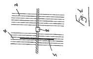
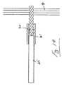
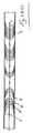
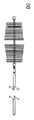
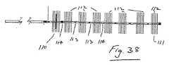
図面を参照すると、本発明による塞栓デバイス1が図示されている。塞栓デバイス1は、展開形態と収縮形態とを有する複数の可撓性ブリストルを備えている。このデバイスは、一連のセグメントを備えている。少なくとも1つのセグメント3は、遠位方向を向いており、1つのセグメント4は、近位方向を向いている。いくつかの場合では、近位セグメント4および遠位セグメント3のみが存在する。 Referring to the drawings, an
近位セグメント4のブリストルは、近位方向を向いており、遠位セグメント3のブリストルは、遠位方向を向いている。 The bristles of the
近位方向を向いたセグメントは、ブリストルが近位方向を向くとともに膜(存在する場合)コーンが近位端のところで開口するセグメントとして定義される。遠位方向を向いたセグメントは、ブリストルが遠位方向を向くとともに膜(存在する場合)コーンが遠位端のところで開口するセグメントとして定義される。 A proximal-facing segment is defined as a segment in which the bristol points proximally and the membrane (if present) cone opens at the proximal end. A distal-facing segment is defined as a segment in which the bristol points distally and the membrane (if present) cone opens at the distal end.
少なくとも1つのセグメント、本例では近位セグメント3は、流れ制限部(本例では、薄いフィルム状の可撓性膜5)を備えている。 At least one segment, in this example the
いくつかの場合では、一連のX線不透過性マーカーが、近位方向を向いたセグメント4と、遠位方向を向いたセグメント3とを分離する。近位マーカー6と、遠位マーカー7と、中間マーカー8と、があってもよい。 In some cases, a series of radiopaque markers separates
1つの場合では、塞栓デバイスは、単一の近位セグメント4および単一の遠位セグメント3のみを備えている。1つの場合では、近位セグメント4および遠位セグメント3は、単一の共通ステムに取り付けられる。近位セグメント4のステムおよび遠位セグメント3のステムは、同一の連続したステムの一部分を形成してもよい。 In one case, the embolic device comprises only a single
塞栓デバイスが2つ以上のセグメントを備えている場合、2つの最近位セグメント間の接続部は、遠位側の接続部よりも強固である。遠位側の接続部は、概して、ヒンジを備えている。 If the embolic device comprises more than one segment, the connection between the two most proximal segments is stronger than the distal connection. The distal connection generally comprises a hinge.
一実施形態では、可撓性膜5がセグメントのうちの少なくとも1つに存在する。膜5は薄いフィルム材料のディスクを備えていてもよい。膜5の可撓性とは、隣接するブリストルの向きによってその向きが制御されること、すなわち、隣接するブリストルが遠位方向を向けさせられると、膜5がその形態を適宜調節することを意味する。したがって、膜5が倒壊状態から(例えば、カテーテル内から)展開されると、ブリストルは、それを拡張形態まで開かせる。膜5は、セグメントに対して近位側または遠位側に配置されてもよい。 In one embodiment, the
1つの場合では、インプラントデバイスは、少なくとも2つのセグメントを備えている。1つの構成では、膜5は最近位セグメントにある。これは、非制限状態で図1,2,21,22,23に概略的に示されている。図示される構成では、膜5は、ブリストルが膜5に対して近位側および遠位側の両方にある状態で、近位セグメント4内に位置している。いくつかの場合では、遠位膜5’があってもよい。 In one case, the implant device comprises at least two segments. In one configuration,
1つの場合では、流れ制限膜が、近位セグメントおよび/または遠位セグメントのブリストル内に長手方向に配置される。流れ制限膜は、ステムから延在していてもよい。流れ制限膜は、複数のアンカーブリストルの外形寸法よりも小さい外形寸法を有していてもよい。流れ制限膜は、ステムに接続されてもよい。いくつかの場合では、流れ制限膜は、ステムへの締まり嵌め部である中央穴を有していてもよい。膜の中央穴は、好ましくは、それが取り付けられるステムよりも小さい。膜の中央穴は、ステムの直径よりも小さい直径を有していてもよい。 In one case, a flow restricting membrane is longitudinally disposed within the bristles of the proximal segment and / or the distal segment. The flow restricting membrane may extend from the stem. The flow restricting membrane may have an outer dimension that is smaller than the outer dimension of the plurality of anchor bristles. The flow restricting membrane may be connected to the stem. In some cases, the flow restricting membrane may have a central hole that is an interference fit to the stem. The central hole in the membrane is preferably smaller than the stem to which it is attached. The central hole of the membrane may have a diameter that is smaller than the diameter of the stem.
インプラントは、カテーテルを通る移送を容易にするための倒壊形態を有している。膜5をセグメント4内に配置することによって、すなわち、ブリストルをそれに対して近位側および遠位側に配置することによって、インプラントが倒壊している間、または、カテーテルを通って押されている間、損傷から保護される。さらに、カテーテルと膜5との間の摩擦が低減される。 The implant has a collapsed configuration to facilitate transport through the catheter. By placing the
1つの構成では、インプラントは、最近位セグメント4のブリストルが近位方向を向き、遠位セグメント3(単数または複数)のブリストルが遠位方向を向くように、倒壊される。膜の向きは、ブリストルの向きによって制御されるので、膜5が近位セグメント内にある場合には、それも近位側を向くことになる。このことは図3に概略的に示されている。 In one configuration, the implant is collapsed so that the bristle of the
図3は、カテーテル10内の2つのセグメント3,4の倒壊形態を示しており、一方が遠位方向を向き、他方が近位方向を向いている。近位セグメント4に示される膜5の外周は近位方向を向いていることに留意されたい。 FIG. 3 shows the collapsed configuration of the two
この形態から展開されると、倒壊形態に類似しているが部分的に拡張した形態が血管内に達成される。このことは、近位セグメント4のブリストルが近位方向を向き、遠位セグメント3のブリストルが遠位方向を向くことを意味している。これは、図4に概略的に示されている。この構成では、インプラントは、いずれかの方向に移動することから固定されることになる。なぜなら、ブリストルの端部は、ブレーキのような態様で作用して、インプラントと壁との間の摩擦を増加させるからである。これとは対照的に、全てのブリストルが遠位方向を向くと、インプラントを遠位方向に押すために必要な力は、インプラントを近位方向に押すために必要な力よりも大きくなる。このため、デバイス逸脱が近位方向に生じやすくなる恐れがある。 When deployed from this configuration, a partially expanded configuration similar to the collapsed configuration is achieved within the vessel. This means that the bristles of the
一実施形態では、膜5は、非制限形態で測定される場合、ブリストルセグメントの直径よりも小さく、デバイスが対象とする血管の直径よりも大きい直径を有している。このため、膜は、血管の外周に接触するのに十分に大きい直径を有している。倒壊状態において移送のためにより大きなカテーテルを必要とする場合、膜が大きくなるほど、インプラントの外形が大きくなる。 In one embodiment, the
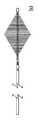
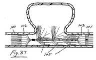
図4に示されるように、デバイスが、インプラントよりも小さい直径で血管内に展開されると、膜5は、円錐状またはカップ状の形状をとり、コーンの開口端が閉口端に対して近位側になる。1つの構成では、展開されたインプラントは、円錐形状の膜5を備えている。コーンの開口端は遠位端に対して近位側にある。動脈では、血液は心臓から遠位動脈樹に向かい、それは近位側から遠位側である。この構成によって、血液がコーンの容積内に流れること、すなわち、コーンの開口が流れと反対側を向くことが確保される。したがって、血液はコーンを拡張させて、膜と血管壁との間のシールを向上させるように作用する(図5)。このようにして、閉塞が容易になる。したがって、コーン内への流れの力(圧力)が大きくなるほど、血管壁に対するシールが改善される。 As shown in FIG. 4, when the device is deployed in a blood vessel with a smaller diameter than the implant, the
図5は、展開形態で膜5に入る流れ方向(閉じられた矢印)および血管壁に対するシールへのその効果の模式図を示している。 FIG. 5 shows a schematic diagram of the flow direction (closed arrow) entering the
他の実施形態では、インプラントは、全てのセグメントが遠位方向を向くように倒壊されてもよい。図6および図7は、倒壊状態にある2つの遠位方向を向いたセグメント3,4(近位セグメントおよび遠位セグメント)の形態を示している。展開されると、近位セグメントおよび遠位セグメントの両方は、遠位方向を向く。同様に、全てのセグメントは、全てが近位方向を向くように倒壊されてもよい。これは、流れが遠位側から近位側となる内腔(例えば、健康な静脈)を閉塞させようとするときに、有利になり得る。図6および図7は、倒壊状態および展開状態にある2つの遠位方向を向いたセグメント(近位セグメントおよび遠位セグメント)の構成を示している。 In other embodiments, the implant may be collapsed so that all segments are oriented distally. 6 and 7 show the form of two distally facing
セグメントの直径に対して膜の様々な程度の小型化は、動脈および静脈を対象とするデバイスにとって好ましい。例えば、静脈は、バルサルバなどの手順中において動脈よりも膨張することが知られている。一般的には、静脈が20〜60%膨張し得るのに対して、動脈は5〜15%膨張する。 Various degrees of membrane miniaturization relative to segment diameter are preferred for devices intended for arteries and veins. For example, veins are known to expand more than arteries during procedures such as Valsalva. In general, veins can expand 20-60% while arteries expand 5-15%.
膜5と血管壁との間の適切なシールを確保するために、セグメントの中央線が、血管の中央線と同一直線上にあることが好ましい。デバイスの、反対方向を向いた少なくとも2つのセグメントを使用することは、この問題を改善すること、すなわち、近位セグメントのブリストルが近位方向を向き、遠位セグメントのブリストルが遠位方向を向くことの助けとなる。これによって、その外周のまわりにおける血管壁に対するコーンの均一なシールが容易になる。図8から分かるように、セグメントが血管と同一直線上にない場合、膜は不安定になる恐れがある。この不安定によって、(例えば、コーンの方向を反対にすることによって)流れが膜形状をコーン状の形状から開くか、変更することがある。図8は、流れを通過させることができる血管中央線との共直線性に乏しい不安定な塞栓デバイスを示している。 In order to ensure a proper seal between the
デバイスは、血管中央線との塞栓デバイスの共直線性改善するための特徴を備えていてもよい。一実施形態では、セグメントの直径は、対象血管の直径よりも十分に大きい。このことは、血管内での塞栓デバイスの安定性を改善し、セグメントと血管中央線との共直線性を容易にする。したがって、インプラントは、対象血管と比べて、十分に大きくなる。0.0385〜0.041インチ、および、0.056−0.056インチの内径のカテーテルによって移送可能な塞栓デバイスについての好ましい寸法が表1および表2に概説されている。その寸法は、図9に概略的に示されている。図9は、非展開状態におけるデバイス寸法(a)および血管直径定義(b)を示している。 The device may comprise features for improving the co-linearity of the embolic device with the vessel centerline. In one embodiment, the segment diameter is sufficiently larger than the diameter of the target vessel. This improves the stability of the embolic device within the blood vessel and facilitates co-linearity between the segment and the blood vessel centerline. Therefore, the implant is sufficiently large compared to the target blood vessel. Preferred dimensions for embolic devices that can be transferred by 0.0385-0.041 inch and 0.056-0.056 inch inner diameter catheters are outlined in Tables 1 and 2. Its dimensions are shown schematically in FIG. FIG. 9 shows device dimensions (a) and vessel diameter definition (b) in the undeployed state.
大型化(セグメント直径と血管直径との直径の差の割合として計算される)は、好ましくは血管直径の少なくとも20%、より好ましくは血管直径の50%、より好ましくはデバイスが埋め込まれる血管直径の少なくとも100%である。例えば、直径が6mmの対象血管について、デバイス直径は、少なくとも7.6mm、好ましくは少なくとも9mm、より好ましくは少なくとも12mmであってもよい。 The enlargement (calculated as the ratio of the difference between the segment diameter and the vessel diameter) is preferably at least 20% of the vessel diameter, more preferably 50% of the vessel diameter, more preferably of the vessel diameter in which the device is implanted. At least 100%. For example, for a target vessel with a diameter of 6 mm, the device diameter may be at least 7.6 mm, preferably at least 9 mm, more preferably at least 12 mm.
静脈における共直線性を確保するために、大型化の程度は、動脈におけるそれと比較して、増大されてもよい。なぜなら、静脈は(例えば、バルサルバ中に)大きく膨張することが知られているからである。1つの構成では、最小の大型化は100%である。 In order to ensure co-linearity in the vein, the degree of enlargement may be increased compared to that in the artery. This is because veins are known to swell greatly (eg, during Valsalva). In one configuration, the minimum size increase is 100%.
1つの構成では、2つのセグメント間の接続部は、複雑な生体構造を通って追跡できる、または、歩行中等の血管の移動に順応できる可撓性を有している。この接続部の可撓性は、良好な血管閉塞を確保するセグメントと膜および血管との良好な共直線性を確保するように制限されることが好ましい。これによって、カテーテル先端を出る際にデバイスが曲がった形態で展開することが防止される。 In one configuration, the connection between the two segments is flexible enough to be tracked through complex anatomy or to accommodate blood vessel movement, such as during walking. The flexibility of this connection is preferably limited to ensure good co-linearity between the segment and membrane and blood vessels that ensure good vascular occlusion. This prevents the device from deploying in a bent configuration upon exiting the catheter tip.
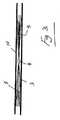
一実施形態では、図10に示されるように、ブリストルセグメントは、同一のステム20上にあり、セグメント21,22の間に隙間23が存在する。他の実施形態では、2つの異なるステム上の2つのセグメント24,25が接続されてもよい。1つの構成では、この接続部は、圧着または溶接されたハイポチューブを備えていてもよい。図10は、同一のステム20上において反対側を向いた2つのブリストルセグメント21,22を備えるデバイスを示している。 In one embodiment, as shown in FIG. 10, the bristol segments are on the
さらに別の実施形態では、同一のセグメントが、近位方向を向いたいくつかのブリストル(および膜)と、遠位方向を向いたいくつかのブリストルと、を有するように、倒壊形態および展開形態で構成されてもよい(図11)。図11は、反対方向において同一のステムを共有し、それらの間に隙間がない2つのブリストルセグメント24,25を備える塞栓デバイスを示している。 In yet another embodiment, the collapsed and deployed configurations so that the same segment has several bristles (and membranes) facing proximally and some bristles facing distally (FIG. 11). FIG. 11 shows an embolic device comprising two
いくつかの場合では、外科医は、デバイスの少なくとも一部分を展開させ、満足できない場合にはそれを再位置決めしたい場合がある。 In some cases, the surgeon may want to deploy at least a portion of the device and reposition it if not satisfied.
1つの場合では、デバイスは、少なくとも1つの近位方向を向いた近位セグメントと、少なくとも1つの遠位方向を向いた遠位セグメントと、を備えている。外科医がデバイスを完全に展開させ、次いで、デバイスを回収して再展開させたい場合、そのまわりでガイドカテーテルを前進させることによってインプラントを回収する動作によって、カテーテル先端を通過する際に近位セグメント(単数または複数)の方向が反転される。このため、インプラントが再展開されると、全てのセグメントは遠位方向を向く。これによって、膜が遠位方向に開かれる。このため、流れが膜の外側を越えて流れることができる場合がある。この状況を回避することが好ましい場合がある。 In one case, the device comprises at least one proximally oriented proximal segment and at least one distally oriented distal segment. If the surgeon wants to fully deploy the device and then retrieve and redeploy the device, the proximal segment (as it passes through the catheter tip) by the operation of retrieving the implant by advancing the guide catheter around it. The direction (s) is reversed. Thus, when the implant is redeployed, all segments are oriented distally. This opens the membrane in the distal direction. For this reason, the flow may be able to flow beyond the outside of the membrane. It may be preferable to avoid this situation.
これを軽減するために、X線不透過性マーキングシステムを使用して、近位方向を向いたセグメント(単数または複数)がカテーテルから展開されているか否かを外科医に注意喚起することができる。したがって、外科医は、近位方向を向いたセグメント(単数または複数)を展開させることなく、遠位方向を向いたセグメントを展開させ、それらの位置を評価することができる。外科医が、遠位方向を向いたセグメントの位置に満足しない場合、それらは、近位方向を向いたセグメントの方向を警告することなく、再度、収められ、それらを展開させる。 To alleviate this, a radiopaque marking system can be used to alert the surgeon whether proximal-facing segment (s) have been deployed from the catheter. Thus, the surgeon can deploy the distal-facing segments and evaluate their position without deploying the proximal-facing segment (s). If the surgeon is not satisfied with the position of the distal-facing segment, they are retracted and deployed without warning of the proximal-facing segment orientation.
1つの構成では、X線不透過性マーカーすなわち遠位マーカー7が、最遠位セグメントの最遠位点のところに存在する。第2のマーカーすなわち中間マーカー8が、遠位方向を向いたセグメント(単数または複数)と近位方向を向いたセグメント(単数または複数)との間に存在する。第3のマーカーすなわち近位マーカー6が、近位方向を向いたセグメントの最近位点のところに存在する。この構成では、遠位マーカー7と中間マーカー8との間の部分は、それらの向きに影響を与えることなく展開、回収/再位置決めされ得る遠位方向を向いたセグメントを形成し、中間マーカー8と第3の近位マーカー6との間の部分は、外科医がデバイスの位置に満足するまで展開されるべきではない近位方向を向いたセグメントを形成する。 In one configuration, a radiopaque marker or
このマーキングシステムを使用したデバイスの展開は、図12(a)〜12(c)に概略的に示されている。図12(a)〜12(c)は、マーキングシステムと、移送および展開の様々な段階中のそれらの位置と、を示している。 Device deployment using this marking system is schematically illustrated in FIGS. 12 (a) -12 (c). FIGS. 12 (a) -12 (c) show the marking system and their location during various stages of transfer and deployment.
1つの場合では、マーカーバンドとして知られるX線不透過性材料のチューブの部分が、セグメント間の接続部に圧着されてもよい。セグメントを接続するためにハイポチューブが使用される場合には、マーカーは、ハイポチューブが適所に圧着される前に、セグメントのステムの一方または両方に配置されてもよい。他の実施形態では、マーカーバンドは、ハイポチューブ接続部に配置されてもよい。さらに別の実施形態では、X線不透過性マーカーバンドは、2つの隣接するセグメントを接続するために使用されてもよい。圧着もしくは溶接、はんだ付け、接着剤もしくは他の手段の使用によって、取り付けを容易にすることができる。他の構成では、マーカーバンドは2つのセグメント間の接続部に対して遠位側または近位側のステムに配置されてもよい。 In one case, a portion of the tube of radiopaque material known as a marker band may be crimped to the connection between the segments. If a hypotube is used to connect the segments, the marker may be placed on one or both of the stems of the segment before the hypotube is crimped in place. In other embodiments, the marker band may be located at the hypotube connection. In yet another embodiment, a radiopaque marker band may be used to connect two adjacent segments. Attachment can be facilitated by the use of crimping or welding, soldering, adhesives or other means. In other configurations, the marker band may be placed on the stem distal or proximal to the connection between the two segments.
一実施形態では、膜は、PTFEの薄いフィルムから形成されていてもよい。一実施形態では、膜は、ポリウレタンなどの薄いフィルムエラストマーから形成されていてもよい。1つの場合では、膜は、ポリエーテルなどの熱可塑性ポリウレタン(例えば、芳香族ポリエーテルウレタン)から形成されていてもよい。一実施形態では、膜は、その中心に小さい穴を備えている。膜をブリストルセグメントに容易に配置するために、隣接するブリストルが、何らかの手段によって倒壊される。こうして、倒壊したブリストルのまわりで膜がより糸で取り付けられ、所望の位置に配置され得る。 In one embodiment, the membrane may be formed from a thin film of PTFE. In one embodiment, the membrane may be formed from a thin film elastomer such as polyurethane. In one case, the membrane may be formed from a thermoplastic polyurethane such as a polyether (eg, aromatic polyether urethane). In one embodiment, the membrane has a small hole in its center. In order to easily place the membrane in the Bristol segment, the adjacent Bristol is collapsed by some means. Thus, the membrane can be threaded around the collapsed Bristol and placed in the desired location.
倒壊したブリストルのまわりで膜を操作して所定位置に配置することは、穴がより大きな直径に伸ばされることを必要とする場合がある。永久的に変形することなくより大きな変形を吸収することができるエラストマーの使用によって、製造におけるこの工程が容易になる。拡張するこの材料の能力によって、製造中にセグメント内への膜の配置が容易になる。 Manipulating the membrane around the collapsed Bristol and placing it in place may require the hole to be stretched to a larger diameter. The use of elastomers that can absorb larger deformations without permanent deformation facilitates this process in manufacturing. The ability of this material to expand facilitates the placement of the membrane within the segment during manufacture.
ポリウレタンなどの材料は、他の材料よりも潤滑なので、膜が、倒壊形態においてセグメントのブリストルに対して適切に保持され、装着中およびカテーテルを通る移送中に引き抜かれ得ないことが確保される。 Since materials such as polyurethane are more lubricious than other materials, it is ensured that the membrane is properly held against the bristles of the segment in a collapsed configuration and cannot be withdrawn during installation and transfer through the catheter.
一実施例では、膜は、薄いフィルム状のニチノールから形成される。この場合、ブリストルは、倒壊し、拡張し、膜を支持することを求められない。 In one embodiment, the membrane is formed from a thin film of nitinol. In this case, Bristol will not be required to collapse, expand and support the membrane.
好ましくは、膜は低剛性である。これによって、その挙動が隣接するブリストルによるブリストルによって支配的となり、血管壁のところで良好なシールを確保するために容易に曲がり得ることが確保される。さらに、固い膜が、長手方向にチャネルを有していてもよい。固い膜についての他の問題は、倒壊形態にあるときに折り畳んで低プロファイルに適合することができないことである。ポリウレタンなどのポリマー膜が使用される場合を考えれば、膜の剛性は、その厚みを薄いフィルムの厚みまで低減することによって、低減され得る。膜についての寸法は、表1および表2に概説されている。また、膜は、PTFE,PETまたはナイロンから形成されていてもよい。PTFEは、潤滑性を向上させて、大きな力を必要とすることなくカテーテル内に塞栓デバイスを通すことができるようになるので、特に適している。 Preferably, the membrane is low in rigidity. This ensures that the behavior is dominated by the bristles by the adjacent bristles and can be easily bent to ensure a good seal at the vessel wall. Further, the hard film may have a channel in the longitudinal direction. Another problem with stiff membranes is that they cannot fold and conform to a low profile when in a collapsed configuration. Considering the case where a polymer membrane such as polyurethane is used, the stiffness of the membrane can be reduced by reducing its thickness to a thin film thickness. The dimensions for the membrane are outlined in Tables 1 and 2. The membrane may be formed from PTFE, PET, or nylon. PTFE is particularly suitable because it improves lubricity and allows the embolic device to pass through the catheter without the need for significant force.
小さい穴のカテーテルを通る移送を可能にするために、倒壊形態にある場合のデバイスの外形ができるだけ低プロファイルであることが好ましい。これによって、カテーテルについての内腔アクセスの部位のところでの血腫および感染症といった合併症が低減される。また、インプラントが外科医の裁量で移送ワイヤから取り外し可能であることが好ましい。 In order to allow transport through a small hole catheter, it is preferred that the profile of the device when in collapsed configuration be as low a profile as possible. This reduces complications such as hematoma and infection at the site of lumen access for the catheter. It is also preferred that the implant be removable from the transfer wire at the surgeon's discretion.
1つの構成では、インプラントは、その近位端に取り外し機構を有している。これによって、外科医は、満足するまでその位置を再調整して、デバイスを取り除くか、インプラントを任意に取り外すことができる。いくつかの構成は、取り外し機構の直径は、ステムの直径よりも大きくてもよく、あるいは、インプラントを目標血管まで移送するのに使用されるカテーテルまたはシース内の空間の大部分を均一に埋めてもよい。 In one configuration, the implant has a removal mechanism at its proximal end. This allows the surgeon to readjust the position until satisfied and remove the device or optionally remove the implant. In some configurations, the diameter of the removal mechanism may be larger than the diameter of the stem, or evenly fills most of the space in the catheter or sheath used to transport the implant to the target vessel. Also good.
この問題に対する他の解決策は、低プロファイルの取り外し機構を使用することである。一実施形態では、捻れワイヤステムが使用されてもよい。この場合、捻れワイヤの形状は、図13に示されるように自然に雄ネジを提供する。次いで、雌ネジがこの雄ネジに螺合される。一実施形態では、雌ネジ機構は、成形ハイポチューブを備えている。このハイポチューブでは、捻れワイヤステムのネジと噛み合うよういに意図されたハイポチューブの内部のネジが適所に形成される。好ましくは、捻れワイヤブラシのピッチは、ネジのピッチである。比較的少ない数のネジが首尾よく使用されてもよい。好ましくは最小2つの雌ネジが使用される。 Another solution to this problem is to use a low profile removal mechanism. In one embodiment, a twisted wire stem may be used. In this case, the shape of the twisted wire naturally provides a male thread as shown in FIG. Next, the female screw is screwed onto the male screw. In one embodiment, the internal thread mechanism includes a molded hypotube. In this hypotube, the internal threads of the hypotube intended to mesh with the twisted wire stem threads are formed in place. Preferably, the pitch of the twisted wire brush is the pitch of the screw. A relatively small number of screws may be used successfully. Preferably, a minimum of two female screws are used.
図13は、天然雌ネジとして捻れワイヤステム30を利用したネジ機構を示している。
この模式図では、雌ネジとして成形ハイポチューブ31が使用される。FIG. 13 shows a screw mechanism using a twisted wire stem 30 as a natural female screw.
In this schematic diagram, a molded
他の実施形態では、雌ネジは、チューブの内側において機械加工されるか、ネジ切りされる。他の構成では、雌ネジは、信頼性の高いネジ取り外し機構を提供する雄ネジのピッチと一致するピッチを有するコイルを備えている。 In other embodiments, the internal thread is machined or threaded inside the tube. In another configuration, the female thread comprises a coil having a pitch that matches the pitch of the male thread that provides a reliable screw removal mechanism.
一実施形態では、雄ネジ30は、最近位セグメントの捻れワイヤステムの一部分である。さらなる実施形態では、雌ネジすなわちハイポチューブ31は、その近位端のところで移送ワイヤ35に取り付けられる。これによって、カテーテルを通るブリストルセグメントの移送および取り外しが容易になる。これは、図14に概略的に示されている。図14は、ネジ機構を示しており、このネジ機構では、ハイポチューブ31が移送ワイヤ35に取り付けられ、ネジ機構によって捻れワイヤステム30から取り外し可能である。捻れワイヤステムを利用しないネジ機構も利用可能である。 In one embodiment,
特に図22および図23を参照すると、1つの場合では、ネジ取り外し機構41とインプラントの最近位セグメント4との間に可撓性部分40が設けられる。一実施形態では、この可撓性部分40は、ヒンジである。この可撓性部分40によって、複雑な生態構造においてインプラントの移送および取り外しが可能になる。また、この可撓性部分40は、インプラントの近位端が患者組織を傷付けないことを確実にするように機能する。 With particular reference to FIGS. 22 and 23, in one case, a
一実施形態では、膜およびブリストルは、取り外し機構と重ならない。この場合、取り外し機構は、ブリストルと膜とが取り外し機構と重ならないように、あるいは、少なくとも最小限に重なるように、セグメントの最近位点から最小距離のところに位置する。 In one embodiment, the membrane and bristol do not overlap the removal mechanism. In this case, the removal mechanism is located at a minimum distance from the closest point of the segment so that the bristol and the membrane do not overlap, or at least minimally overlap the removal mechanism.
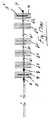
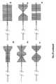
多数の潜在的なデバイスの構成が図15〜18に示されている。図15(a)および図15(b)では、2つのセグメント、すなわち、膜4を含む近位セグメントと、遠位セグメントと、が存在する。マーカーバンド6,7,8が上述の通り位置決めされている。 A number of potential device configurations are shown in FIGS. In FIG. 15 (a) and FIG. 15 (b), there are two segments: a proximal segment containing the
図16(a)および図16(b)を参照すると、この場合、追加的な遠位セグメント60が存在し、セグメント間の移動を吸収するために、遠位セグメント同士の間にヒンジ式接続部61が設けられている。 Referring to FIGS. 16 (a) and 16 (b), in this case there is an additional
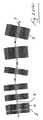
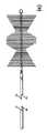
図17(a)および図17(b)を参照すると、この場合、最遠位セグメントも膜5’を備えている。膜5’は、展開形態において遠位方向を向いた開口を有している。最遠位セグメントと、隣接するセグメントと、の間に比較的固い接続部62が設けられている。 Referring to FIGS. 17 (a) and 17 (b), in this case, the most distal segment also comprises a membrane 5 '. The membrane 5 'has an opening facing in the distal direction in the deployed configuration. A relatively
図18(a)および図18(b)は、図17と類似のデバイスを示しており、ここでも、展開されたときに安定性を増大するために、最遠位セグメントと、隣接するセグメントと、の間に比較的固い接続部62が設けられている。この場合、この接続部は、ハイポチューブの一部によって補強されてもよいし、ハイポチューブの一部によって提供されてもよい。 FIGS. 18 (a) and 18 (b) show a device similar to FIG. 17, again with the most distal segment and adjacent segments to increase stability when deployed. A relatively
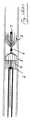
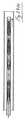
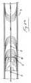
図19および図20は、完全な塞栓デバイス構成を示している。梱包形態では、使用準備ができたときに、インプラントはローディングチューブ50内に格納されている。このローディングチューブ50は、止血弁52と、フラッシングのためのサイドアーム51と、を有するチューブを備えている。移送ワイヤ55は、インプラントの近位端に取り付けられ、止血弁を通過する。インプラントは、目標部位に移送するために、ローディングチューブ50からカテーテル内に押され得る。一実施形態では、ローディングチューブは、デバイスを目標血管に移送するのに使用されるカテーテルのルアー内に容易に嵌め込むことができるようにするために、その遠位端にテーパ部を有している。 19 and 20 show a complete embolic device configuration. In the packaged form, the implant is stored in the
上述したように、インプラントは、ローダからカテーテル内に押されて、治療部位まで押される。ローダの例が図20に示されている。一実施形態では、ローディングチューブは、約2.9mmの外径と、約1.65mmの内径と、を有する、PTFEなどの潤滑材料から形成されている。このローディングチューブは、0.056−0.057”5F移送カテーテルおよび0.035”−0.038”4Fr移送カテーテルの両方と互換性がある。 As described above, the implant is pushed from the loader into the catheter and to the treatment site. An example of a loader is shown in FIG. In one embodiment, the loading tube is formed from a lubricating material, such as PTFE, having an outer diameter of about 2.9 mm and an inner diameter of about 1.65 mm. This loading tube is compatible with both 0.056-0.057 "5F transfer catheters and 0.035" -0.038 "4Fr transfer catheters.
他の実施形態では、ローディングチューブは、その遠位端のところにテーパ部を有しており、それによって、デバイスを目標血管に移送するのに使用される様々なハブ形状の多数のカテーテルと互換可能となる。ローディングチューブ55のテーパ部56は、インプラントの遠位セグメントのブリストル58を円錐形状にすることによって機能する。ローダからの出口では、インプラントが引っ掛かることなくローディングチューブから自由に押され得ることを確保するカテーテルハブの内径のプロファイルよりも小さいプロファイルとなるように、ブリストルがじょうご状になっている。これによって、チューブ/カテーテルの境界の前後、および、移送カテーテル内における円滑な移行が可能になる。 In other embodiments, the loading tube has a taper at its distal end, thereby compatible with multiple catheters of various hub shapes used to transfer the device to the target vessel. It becomes possible. The taper 56 of the
1つの好ましい実施形態では、ローディングチューブの外径は2.9mmであり、内径は1.65mmである。遠位テーバ部は、0.8mm〜1.3mmの内径を有しており、1〜6mmの長さにわたってテーパ状になっている。 In one preferred embodiment, the loading tube has an outer diameter of 2.9 mm and an inner diameter of 1.65 mm. The distal taber portion has an inner diameter of 0.8 mm to 1.3 mm and is tapered over a length of 1 to 6 mm.
セグメント、膜および接続部の様々な構成が図25〜29に示されている。 Various configurations of segments, membranes and connections are shown in FIGS.
いくつかの場合では、移送カテーテル内でのスペースの制約に起因して、近位ブリストルセグメントおよび遠位ブリストルセグメント内に異なる数のブリストルを備えることが好ましいことがある。これによって、移送および展開中におけるカテーテル内での過剰な摩擦を防止しつつ、血栓形成を促進するとともにデバイス逸脱を防止するブリストルの数を最大化することができる。このことは、インプラントの1つのブリストルセグメントが膜を備えている場合に特に重要である。なぜなら、膜自体が場所をとるからである。より多くのブリストルを追加することをさらに可能にするために、ステムの直径を最小化することも好ましい。ステムワイヤは、好ましくは、ブリストルが、捻られたときに、ステムワイヤの塑性変形によって固定的に保持されることを確実にするのに十分な直径を有している。次の表は、インプラントのための材料および寸法の好ましい組み合わせを含んでいる。 In some cases, it may be preferable to have different numbers of bristles in the proximal and distal bristol segments due to space constraints in the transfer catheter. This maximizes the number of bristles that promote thrombus formation and prevent device deviation while preventing excessive friction within the catheter during transfer and deployment. This is particularly important when one bristle segment of the implant is provided with a membrane. This is because the film itself takes up space. It is also preferable to minimize the diameter of the stem in order to make it possible to add more bristles. The stem wire preferably has a diameter sufficient to ensure that the bristol is held securely by plastic deformation of the stem wire when twisted. The following table contains preferred combinations of materials and dimensions for the implant.

いくつかの場合では、血管閉塞のためのより長いデバイスを使用することが好ましいことがある。例えば、卵巣静脈では、5cm〜15cmのデバイス、あるいは、血管長全体を処理するために、25cmのデバイスですら必要になる場合がある。そのような血管では、大きな血管(例えば、10mmの直径)においてでさえ、より小さいブリストル径が適切となることがある。なぜなら、セグメントの長さおよび数が増大することに起因してブリストルの数が増加することは、十分な固定力が達成されることを意味するからである。ブリストルの数が増大することと、ブリストルの直径が低減することと、を組み合わせることによって、カテーテルを通る前進およびカテーテルからの展開のための力を小さくすることができる。次の表は、いくつかの好ましい組み合わせを概説している。 In some cases it may be preferable to use a longer device for vascular occlusion. For example, in the ovarian vein, a 5 cm to 15 cm device or even a 25 cm device may be required to process the entire vessel length. In such vessels, a smaller bristol diameter may be appropriate even in large vessels (eg, 10 mm diameter). This is because an increase in the number of bristles due to an increase in the length and number of segments means that a sufficient securing force is achieved. By combining the increase in the number of bristles and the reduction in the diameter of the bristles, the force for advancement through the catheter and deployment from the catheter can be reduced. The following table outlines some preferred combinations.
いくつかの場合では、標準的なカテーテルまたはシース(これは、通常、0.035〜0.038インチの内径を有している)を使用して目標血管にアクセスすることができない。これらの場合では、カテーテルの範囲は、マイクロカテーテルとして知られて開発されてきた。これらのカテーテルは、優れた可撓性を示し、典型的には3.3French未満の外径を有している。これらのカテーテルの内径は、0.012〜0.029インチの範囲に及ぶ。標準的な内径は、0.021、0.024および0.027インチである。そのようなカテーテルとの互換性について、次の特性を有する本発明のデバイスが好ましい。 In some cases, a standard catheter or sheath (which typically has an inner diameter of 0.035 to 0.038 inches) cannot be used to access the target vessel. In these cases, the catheter range has been developed known as a microcatheter. These catheters exhibit excellent flexibility and typically have an outer diameter of less than 3.3 French. The internal diameter of these catheters ranges from 0.012 to 0.029 inches. Standard inner diameters are 0.021, 0.024 and 0.027 inches. For compatibility with such catheters, devices of the present invention having the following characteristics are preferred.
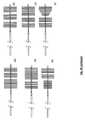
セグメント間の隙間を含む様々な形状が使用されてもよい。一実施形態では、均一な直径のブリストルセグメントが使用されてもよい(図30(a))。 Various shapes including gaps between segments may be used. In one embodiment, a uniform diameter bristol segment may be used (FIG. 30 (a)).
ブリストルセグメントの近位直径がブリストルセグメントの遠位直径よりも小さいテーパ部を使用することによって、マイクロカテーテルを通る移送のために低プロファイルの倒壊形態が達成され得る。これは、図30(b)に概略的に示されている。遠位ブリストルは遠位側においてステム上に倒壊する必要がなく、一方、近位ブリストルは遠位側に存在する全てのブリストル上にあるので、これは達成可能である。 By using a taper where the proximal diameter of the Bristol segment is smaller than the distal diameter of the Bristol segment, a low profile collapsed configuration can be achieved for transport through the microcatheter. This is schematically shown in FIG. 30 (b). This is achievable because the distal bristles need not collapse on the stem on the distal side, while the proximal bristles are on all the bristles present on the distal side.
逸脱を防止するために血管内にインプラントを適切に固定することを確実にするために、ブリストルセグメントの特定部分が、血管の直径に対して最小限大きくなることが具現化されるように構成されてもよい。導入されるテーパの程度は、これによって操作されてもよい。1つの構成では、ブリストルセグメントの最小径は、少なくとも目標血管の直径の最小径である。例えば、図30(f)では、インプラントの相対的に直径が小さい近位部分は、少なくとも、目標血管の相対的に直径が小さい近位部分であってもよく、一方、相対的に大きい直径は、目標血管よりも実質的に大きくてもよい。一実施形態では、セグメントの相対的に直径が小さい部分は、2〜4mmであってもよく、一方、ブリストルセグメントの相対的に直径が大きい部分は、4〜8mmであってもよい。他の実施形態では、ブリストルセグメントの直径は、目標血管と略同一であってもよい。 In order to ensure proper fixation of the implant within the vessel to prevent deviation, it is configured to embody that a particular portion of the bristol segment is minimally increased with respect to the diameter of the vessel. May be. The degree of taper introduced may be manipulated thereby. In one configuration, the minimum diameter of the bristol segment is at least the minimum diameter of the target vessel. For example, in FIG. 30 (f), the relatively small diameter proximal portion of the implant may be at least the relatively small diameter proximal portion of the target vessel, while the relatively large diameter is It may be substantially larger than the target blood vessel. In one embodiment, the relatively small diameter portion of the segment may be 2-4 mm, while the relatively large diameter portion of the bristol segment may be 4-8 mm. In other embodiments, the diameter of the bristol segment may be approximately the same as the target vessel.
他の構成では、2つのテーパ部が形成されたセグメントが使用されてもよく(図30(c))、あるいは、多数の個々のテーパ部が形成されたセグメントが使用されてもよい(図30(d))。 In other configurations, a segment with two tapered portions may be used (FIG. 30 (c)), or a segment with multiple individual tapered portions may be used (FIG. 30). (D)).
隙間を使用することによって、効率(ブリストルの数の増加)をさらに改善することができ、それによって、ブリストルは、低プロファイルのインプラントを倒壊状態に維持しつつ、カテーテル内に配置され得る。より多くの繊維によって、より良好なアンカー力が確保されるとともに、血流との干渉が増大し、その結果、より良好な血栓形成が得られるとともに、閉塞させるための時間が短くなる。図30(m〜r)および図30(d)にいくつかの例が示されている。これらの特徴(隙間およびテーパ部)の任意の組み合わせによって、インプラントを血管内に固定して血管閉塞を生じさせる効果が増大する。 By using gaps, the efficiency (increased number of bristles) can be further improved so that the bristles can be placed in the catheter while keeping the low profile implant in a collapsed state. More fibers ensure a better anchoring force and increase interference with the blood flow, resulting in better thrombus formation and a shorter time to occlude. Some examples are shown in FIGS. 30 (m to r) and FIG. 30 (d). Any combination of these features (gap and taper) increases the effectiveness of securing the implant within the vessel and causing vessel occlusion.
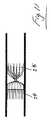
マイクロカテーテルを通って装着するために十分に低いプロファイルを可能にする他の手段は、様々なタイプ(例えば、様々な特性)のブリストルを使用することである。例えば、図31に示されるように、迅速な血栓形成および血管閉塞を生じさせるために、直径が小さい多数の繊維がセグメントの1つの領域に組み込まれてもよい。同様に、より大きな直径のより少ない数の繊維が組み込まれてもよい。一実施形態では、直径が0.0007インチの繊維群、および、0.001インチの繊維群が使用される。他の場合では、0.001および0.0015インチの繊維群が使用される。 Another means of allowing a sufficiently low profile for mounting through a microcatheter is to use various types (eg, various properties) of bristles. For example, as shown in FIG. 31, multiple fibers with a small diameter may be incorporated into one region of the segment to cause rapid thrombus formation and vascular occlusion. Similarly, a smaller number of fibers of larger diameter may be incorporated. In one embodiment, 0.0007 inch diameter fibers and 0.001 inch fibers are used. In other cases, 0.001 and 0.0015 inch fiber groups are used.
インプラントがカテーテル内に配置されると、それは倒壊状態になる。1つのセグメントとの全てのブリストルが、全て1つの方向を向くように倒壊されると、ブリストルは、1つずつ重ねられる。これによって、倒壊状態のセグメントのプロファイルが増大する。より多くのブリストルを有するより長いセグメントは、倒壊状態においてより高プロファイルであることを意味する。倒壊状態においてプロファイルを低減する1つの手段は、繊維のいくつかを、遠位方向を向くように倒壊させるとともに、他の繊維を、近位方向を向くように倒壊させることである。このことは、図32に概略的に示されている。 When the implant is placed in the catheter, it becomes collapsed. When all the bristles with one segment are collapsed so that they all face one direction, the bristles are stacked one by one. This increases the profile of the collapsed segment. A longer segment with more bristles means a higher profile in the collapsed state. One means of reducing the profile in the collapsed state is to cause some of the fibers to collapse in the distal direction and other fibers to collapse in the proximal direction. This is shown schematically in FIG.
展開の後、ブリストルセグメントは、レシース(resheath)されてもよい。これは、もともと近位方向を向いていた全ての繊維を、それらが遠位方向を向くように反転される。一実施形態では、全てのブリストルをマイクロカテーテルに入れることができるようにするのに十分な空間がマイクロカテーテル内に存在する。他の構成では、セグメントの最遠位部分は、ブリストルのための空間が十分ではない(すなわち、セグメントの全ての繊維が遠位方向を向いたときに過剰に高プロファイルである)ことに起因して、マイクロカテーテルに完全には入らない場合がある。 After deployment, the Bristol segment may be resheathed. This reverses all the fibers that were originally oriented in the proximal direction so that they are oriented in the distal direction. In one embodiment, there is sufficient space in the microcatheter to allow all bristles to enter the microcatheter. In other configurations, the most distal portion of the segment is due to insufficient space for Bristol (ie, an excessively high profile when all the fibers of the segment are oriented distally) In some cases, the microcatheter may not enter completely.
さらに別の実施形態では、ブリストルセグメントの量および構成は、不十分な空間に起因して全ての繊維がカテーテルに入ることができないまでも、カテーテルの外部に留まるブリストルがカテーテルの中央線に対して略平行に整合され、その結果、血管壁に接触しないように、方向が変えられてもよい。これによって、外科医がインプラントを取り除くこと、または、その位置を変更することを希望する場合に、外科医が血管壁の損傷または削剥を生じさせることが確実になる。 In yet another embodiment, the amount and configuration of the bristol segments is such that the bristles that remain outside the catheter are relative to the centerline of the catheter, even though not all fibers can enter the catheter due to insufficient space. The orientation may be changed so that they are aligned substantially parallel and as a result do not contact the vessel wall. This ensures that if the surgeon wishes to remove the implant or change its position, the surgeon will cause damage or abrasion of the vessel wall.
さらに別の実施形態では、遠位セグメントと近位セグメントとの間に伸張可能な接続部が存在する。これは、特に、近位セグメントブリストルが遠位セグメントブリストルと重なることに起因して、倒壊したプロファイルがレシースされるには大きすぎる場合に有利であろう。外科医が近位セグメントを引っ張ってカテーテル内に入れる際、および、遠位セグメントがカテーテルに入り始めて抵抗が生じる際に、伸張可能な接続部は、伸びて、セグメント間に生じる隙間を増大させるか、当該隙間が生じることを可能にする。隙間の大きさを増大させることによって、より多くまたは全てのセグメントが倒壊してカテーテル内に入ることが可能になる。図35(a)は、取り外し状態における、伸張可能な接続部を有するそのような構成を示している。図35(b)は、伸張可能な接続部が拡大された、装着状態における同じ構成を示している。図35(c)は、レシース工程を示しており、カテーテルは近位セグメントブリストルを倒壊させている。この動作も、伸張可能な接続部の伸びを生じさせて、近位ブリストルが遠位ブリストルに重なる程度を緩和する。
伸張可能な接続部は、取り外しの際にその元の長さまで戻ることができるスプリングまたは弾性要素を備えていてもよい。伸張可能な接続部は、非弾性型要素を備えていてもよい。In yet another embodiment, there is an extensible connection between the distal segment and the proximal segment. This may be advantageous particularly when the collapsed profile is too large to be relieved due to the proximal segment bristles overlapping the distal segment bristles. When the surgeon pulls the proximal segment into the catheter, and when the distal segment begins to enter the catheter and resistance occurs, the stretchable connection stretches to increase the gap created between the segments, The gap can be generated. Increasing the size of the gap allows more or all segments to collapse and enter the catheter. FIG. 35 (a) shows such a configuration with a stretchable connection in the detached state. FIG. 35B shows the same configuration in the mounted state in which the expandable connecting portion is enlarged. FIG. 35 (c) shows the rescue process, where the catheter collapses the proximal segment bristol. This action also causes the stretchable connection to stretch, mitigating the extent to which the proximal bristles overlap the distal bristles.
The extensible connection may comprise a spring or elastic element that can return to its original length upon removal. The extensible connection may comprise an inelastic element.
ブリストルセグメントのプロファイルを低減する他の手段は、セグメントが非円形断面を有するようにセグメントを切り取ることである。これは、図33に概略的に示されている。(a)は、切り取られていない従来のブリストルセグメントを示している。図33(b)は、直径が小さい領域が存在するように切り取られたセグメントを示している。このようにして、相対的に長い繊維は、インプラントが血管内で良好に固定されることを確実にするように機能し、一方、相対的に短い繊維は、血栓形成を支援する。他の非円形形状、例えば、図33(c)の正方形、三角形、または他の形状が使用されてもよい。 Another means of reducing the profile of the Bristol segment is to cut the segment so that the segment has a non-circular cross section. This is shown schematically in FIG. (A) has shown the conventional Bristol segment which is not cut off. FIG. 33B shows a segment cut out so that a region having a small diameter exists. In this way, the relatively long fibers function to ensure that the implant is well anchored within the blood vessel, while the relatively short fibers assist in thrombus formation. Other non-circular shapes may be used, such as the square, triangle, or other shapes of FIG.
いくつかのインプラントでは、膜または流れ閉塞部材が備えられていてもよい。多数の構成が図34に概略的に示されており、これらは、マイクロカテーテルについての空間制約の問題を解決する。膜は、倒壊形態にあるインプラントのプロファイルに大きく寄与するので、倒壊形態においてセグメントの全体的に低プロファイルである領域に膜を配置することが有利となる場合がある。セグメントのこの低プロファイル領域は、上述の任意の手段(低減されたセグメントの直径、直径が小さいブリストルの使用、テーパ部の使用などが含まれる)によって達成され得る。 In some implants, a membrane or flow occlusion member may be provided. A number of configurations are shown schematically in FIG. 34, which solves the space constraint problem for microcatheter. Because the membrane contributes significantly to the profile of the implant in the collapsed configuration, it may be advantageous to place the membrane in an area that is an overall low profile of the segment in the collapsed configuration. This low profile region of the segment may be achieved by any of the means described above, including reduced segment diameter, use of smaller diameter bristles, use of tapers, etc.
上述したように、インプラントは、ネジ機構によって取り外されてもよい。一実施形態では、取り外し機構の雌部分または雄部分は、X線不透過性材料を含有していてもよい。これは、使用中に取り外しの視認を容易にするためである。さらに別の実施形態では、ネジ取り外し機構の雌部分および雄部分の両方がX線不透過性を有しており、それによって、外科医は、雌から雄が取り外されるのを明確に見ることができる。 As described above, the implant may be removed by a screw mechanism. In one embodiment, the female or male portion of the removal mechanism may contain a radiopaque material. This is for facilitating visual recognition of the removal during use. In yet another embodiment, both the female and male portions of the screw removal mechanism are radiopaque so that the surgeon can clearly see the male being removed from the female. .
一実施形態では、ネジ取り外し機構の雄部分はインプラントに取り付けられ、雌は移送ワイヤに取り付けられる。他の実施形態では、ネジ取り外し機構の雌部分はインプラントに取り付けられ、雄部分は移送ワイヤに取り付けられる。 In one embodiment, the male portion of the screw removal mechanism is attached to the implant and the female is attached to the transfer wire. In other embodiments, the female portion of the screw removal mechanism is attached to the implant and the male portion is attached to the transfer wire.
図9(a)に示されるように、セグメント間の隙間によって、移送中および修正中の低プロファイルを容易にすることができる。修正中において、カテーテル内へのインプラントのレシースによって、隙間は、膜を備えていてもよい近位セグメントの繊維が近位方向を向いた形態から遠位方向を向いた形態へ変更されるときに、低プロファイルを容易にする。インプラントの修正が望ましい特性ではない場合には、セグメント間の隙間は、1mm程度の小さなものであってもよい。他の実施形態では、遠位セグメントと近位セグメントとの間に隙間がなくてもよい。 As shown in FIG. 9 (a), the gap between the segments can facilitate a low profile during transfer and correction. During modification, the sheath of the implant into the catheter causes the gap to change when the fibers of the proximal segment, which may comprise a membrane, are changed from a proximal-facing configuration to a distal-facing configuration. Easy, low profile. If implant modification is not a desirable characteristic, the gap between segments may be as small as 1 mm. In other embodiments, there may be no gap between the distal segment and the proximal segment.
マイクロカテーテルを通って移送可能なデバイスのさらなる実施形態が表5に記載されている。この構成は、図24に示された構成と類似している。1つの構成では、近位セグメントよりも遠位セグメントに、より大きなブリストル径が使用される。これは、遠位セグメントからの径方向外向きの力が最大になり、デバイスを固定する助けとなることを確保するためである。マイクロカテーテルを通って移送可能である状態で近位セグメントに膜を配置することを容易にするために、より小さいブリストル径が近位セグメントで使用されてもよい。 Additional embodiments of devices that can be transported through the microcatheter are described in Table 5. This configuration is similar to the configuration shown in FIG. In one configuration, a larger bristol diameter is used for the distal segment than the proximal segment. This is to ensure that the radially outward force from the distal segment is maximized and helps to secure the device. A smaller bristol diameter may be used in the proximal segment to facilitate placement of the membrane in the proximal segment while being transportable through the microcatheter.
上述したように、血管と比較してデバイス径を大きくすること(セグメント径と血管径との間での直径割合差として計算される)は、好ましくは、少なくとも20%、より好ましくは血管径の50%、さらに好ましくはデバイスが埋め込まれる血管の直径の少なくとも100%である。さらに好ましくは、150%の大型化が採用される。 As mentioned above, increasing the device diameter relative to the blood vessel (calculated as the diameter ratio difference between the segment diameter and the blood vessel diameter) is preferably at least 20%, more preferably of the blood vessel diameter. 50%, more preferably at least 100% of the diameter of the blood vessel in which the device is implanted. More preferably, an increase in size of 150% is employed.
塞栓処置
塞栓処置は、様々な外科医、主にインターベンショナル・ラジオロジスト、血管執刀医、インターベンショナル心臓専門医によって始められる。閉塞についての様々な症状が存在する。頻繁に行われる処置、および、関連する外科医は、以下の表に要約されている。Embolization The embolization is initiated by various surgeons, mainly interventional radiologists, vascular surgeons, and interventional cardiologists. There are various symptoms of obstruction. The frequently performed procedures and associated surgeons are summarized in the following table.
塞栓では、一般的に、流れ方向は近位から遠位である(順行、すなわち、心臓から離れる方向)。これは、動脈における自然な流れ方向である。健康な静脈では、流れ方向は一般的に反対になる(逆行、すなわち、心臓に向かう方向)。しかしながら、一般的には、患者において逆流で行われ、これは、流れが順行にもなることを意味している。 In an embolus, the flow direction is generally proximal to distal (forward, ie away from the heart). This is the natural flow direction in the artery. In healthy veins, the direction of flow is generally opposite (reverse, ie, toward the heart). However, it is generally done in the patient with a backflow, which means that the flow is also antegrade.
流れは、一般的に、近位から遠位であるので、ブリストルが近位側を向いた状態で、膜をデバイスの近位端のところで近位側に開口するように設けることが好ましい。これによって、流れが膜の外側のまわりを通過する可能性が低減される。 Since the flow is generally proximal to distal, it is preferred to provide the membrane to open proximally at the proximal end of the device with the bristol facing proximally. This reduces the possibility that the flow will pass around the outside of the membrane.
遠位端および近位端での膜を使用した動脈瘤の治療
通常、血液は、動脈瘤嚢を満たしつつ動脈瘤を通過して、親血管において近位側から遠位側へ流れる。したがって、動脈瘤に向けた近位側の流入の閉塞が嚢内への流入を防止すべきであるということが直感的に理解できるように思われ得る。しかしながら、状況によっては、近位血管の閉塞は、血管の血行動態を局所的に変更することができ、このことは、流れが遠位側から動脈瘤に移動して、動脈瘤嚢をさらに満たすとともに加圧することができることを意味している。この状況では、外科医は、動脈瘤に対して近位側および遠位側にある親血管を閉塞させようとする。これは、動脈瘤のフロントドア・バックドア治療として知られている。Treatment of aneurysms using membranes at the distal and proximal ends Normally, blood flows from the proximal side to the distal side in the parent vessel through the aneurysm filling the aneurysm sac. Thus, it may seem intuitive that a proximal inflow occlusion towards the aneurysm should prevent inflow into the sac. However, in some situations, occlusion of the proximal vessel can locally alter the hemodynamics of the vessel, which causes the flow to move from the distal side to the aneurysm, further filling the aneurysm sac It means that it can be pressurized together. In this situation, the surgeon attempts to occlude the parent vessel proximal and distal to the aneurysm. This is known as an aneurysm front door / back door treatment.
一実施形態では、塞栓デバイスは、塞栓デバイス上に近位膜および遠位膜の両方が存在するように構成されてもよい。これによって、動脈瘤に対する近位側および遠位側の両方での親血管の迅速な閉塞が可能になる。したがって、近位膜は、動脈瘤嚢に対して近位側になるように構成され、一方、遠位膜は、動脈瘤嚢に対して遠位側になる。好ましい構成では、膜または近位ブリストルセグメントは、近位側に開口し、遠位セグメントの膜は、遠位方向に開口する。 In one embodiment, the embolic device may be configured such that both the proximal and distal membranes are present on the embolic device. This allows for rapid occlusion of the parent vessel, both proximal and distal to the aneurysm. Thus, the proximal membrane is configured to be proximal to the aneurysm sac, while the distal membrane is distal to the aneurysm sac. In a preferred configuration, the membrane or proximal bristol segment opens proximally and the membrane of the distal segment opens distally.
各々が膜102,103を有する2つのブリストルセグメント100,101を備える1つの構成が図36に示されている。より大きな動脈瘤を克服するためにいくつかの追加的なセグメントを有する他の構成が図37に示されている。 One configuration comprising two
長いデバイスにおける強固で可撓性を有する相互接続の使用
いくつかの場合では、セグメントの特性は、可撓性を有する接続部が必要ないようなものであってもよい。短いデバイスでは、可撓性を有する接続部は必要ない場合がある。しかしながら、長いデバイスでは、いくらかの可撓性が必要になることがある。インプラント長5cmごとに少なくとも1つの可撓性接続部が存在することが好ましい。Use of strong and flexible interconnects in long devices In some cases, the characteristics of the segment may be such that a flexible connection is not required. For short devices, flexible connections may not be necessary. However, long devices may require some flexibility. There is preferably at least one flexible connection for every 5 cm of implant length.
1つの構成では、デバイスは、多数の遠位ブリストルセグメントを有しており、これらの遠位セグメントは、可撓性および剛性の両方を有する接続部を介して接続される。これは、全ての遠位セグメント間の可撓性を有する接続部が、可撓性が過剰になることに起因して、カテーテルを通って移送されるときのインプラントの押す能力が損なわれる結果を招く場合に必要となることがある。これは、特に、ヒンジを備える非常に可撓性の大きい接続部が使用される場合であり得る。少なくとも1つの可撓性を有する接続部を、剛性を有する、または、より剛性の高い接続部と置き換えることによって、インプラントの柱剛性、ひいては、その押す能力が向上する。これによって、移送カテーテルを通ってインプラントを押すために必要な力が低減される。可撓性を有する部分の間に間欠的に剛性を有する接続部を配置して、長さに沿った良好な押す能力を維持しつつ、長さに沿った良好な可撓性を確保することが好ましい場合がある。 In one configuration, the device has multiple distal bristol segments that are connected via connections that are both flexible and rigid. This results in a flexible connection between all the distal segments that impairs the ability to push the implant as it is transported through the catheter due to excessive flexibility. It may be necessary when inviting. This may be the case especially when very flexible connections with hinges are used. By replacing the at least one flexible connection with a rigid or stiffer connection, the column stiffness of the implant and thus its pushing ability is improved. This reduces the force required to push the implant through the transfer catheter. Placing intermittently rigid connecting portions between the flexible parts to ensure good flexibility along the length while maintaining good pushing ability along the length May be preferred.
1つのそのようなデバイスが図38に示されている。このデバイスは、近位セグメント110および遠位セグメント111と、複数の中間セグメント112と、を有している。セグメント間の接続部のいくつかは、ヒンジ状であり(113)、他の幾つかは比較的強固である(114)。 One such device is shown in FIG. The device has a
ブリストルセグメント内に膜があることが好ましい。ブリストル操作器具が使用されてもよく、ブリストルのいくつかは、ブリストルがステムと整合されるように操作されてもよい。流れ制限膜が、ブリストル間に取り付けられ、その後、ブリストルは器具から取り外される。逆も同様である。 Preferably there is a membrane in the Bristol segment. A bristol manipulator may be used and some of the bristles may be manipulated such that the bristol is aligned with the stem. A flow restricting membrane is attached between the bristles, after which the bristles are removed from the instrument. The reverse is also true.
ブリストルがもとに戻ったとき、膜は、近位側のブリストルと、遠位側のブリストルと、の間にあり、これらのブリストルによって保護され、固定される。 When Bristol is restored, the membrane is between the proximal Bristol and the distal Bristol and is protected and secured by these Bristols.
隣接するブリストルによって膜が制御されることを確実にするために、膜に対する遠位側および近位側の両方にいくつかのブリストルが存在するべきである。1つの構成では、膜130は、ブリストルの50%が膜に対して近位側にあり、50%が膜に対して遠位側にあるように配置される。セグメントに対して近位側の構造(例えば、取り外し機構、または、移送ワイヤ)上に膜が重なることを防止するために、膜は、セグメント内でより遠位側に配置されてもよい。1つの構成では、繊維の60%が膜に対して近位側にあり、40%が膜に対して遠位側にある。他の構成では、繊維の70%が膜に対して近位側にあり、30%が膜に対して遠位側にある。他の構成では、繊維の80%が膜に対して近位側にあり、20%が膜に対して遠位側にある。 To ensure that the membrane is controlled by the adjacent bristles, there should be some bristles both distal and proximal to the membrane. In one configuration, the membrane 130 is positioned so that 50% of the bristol is proximal to the membrane and 50% is distal to the membrane. The membrane may be placed more distally within the segment to prevent the membrane from overlying a structure proximal to the segment (eg, a removal mechanism or transfer wire). In one configuration, 60% of the fibers are proximal to the membrane and 40% are distal to the membrane. In other configurations, 70% of the fibers are proximal to the membrane and 30% are distal to the membrane. In other configurations, 80% of the fibers are proximal to the membrane and 20% are distal to the membrane.
膜の穴径および締まり嵌め
ブリストルセグメント内に膜を配置することによって、使用中または展開されたときに膜がセグメントに沿って近位方向または遠位方向に並進することを抑制することが確実になる。膜の固定は、膜の穴と、セグメントステムの穴と、の間の締まり嵌め部によって、さらに改善される。これを達成するために、膜の穴は、セグメントのステムよりも小さくなるべきである。ステム上に配置されると、ステムと、膜の穴と、の直径の不一致が、2つの表面と締まり嵌め部との間に摩擦を生じさせる。Membrane hole diameter and interference fit Placing the membrane within the Bristol segment ensures that the membrane is prevented from translating proximally or distally along the segment when in use or deployed. Become. Membrane fixation is further improved by an interference fit between the hole in the membrane and the hole in the segment stem. To achieve this, the membrane hole should be smaller than the stem of the segment. When placed on the stem, the diameter mismatch between the stem and the membrane hole causes friction between the two surfaces and the interference fit.
締まり嵌め部を達成するために、膜の穴は、ステムの直径よりも小さくなるべきである。好ましくは、膜の穴径は、ステムの直径よりも小さい、少なくとも0.001インチであるべきである。より好ましくは、膜の穴径は、ステムの直径よりも小さい、少なくとも0.002インチであるべきである。 In order to achieve an interference fit, the hole in the membrane should be smaller than the diameter of the stem. Preferably, the hole diameter of the membrane should be at least 0.001 inch, which is smaller than the diameter of the stem. More preferably, the hole diameter of the membrane should be at least 0.002 inches, which is smaller than the diameter of the stem.
膜の穴が小さすぎると、膜をセグメントに適合させて、ステムと膜の穴との間に干渉がなく、あるいは、隙間が存在し得るように、元に戻らない穴の変形を生じさせるために、過剰な伸びが必要となる場合があることが理解されるであろう。この場合、一部の流れがこの隙間を通過して、閉塞についてのデバイス性能を抑制し得る。膜の穴は、ステムの直径よりも小さい、40%以下であるべきである。 If the membrane hole is too small, it will cause the membrane to fit into the segment and cause deformation of the irreversible hole so that there is no interference between the stem and the membrane hole or there may be a gap It will be appreciated that excessive elongation may be required. In this case, a part of the flow can pass through this gap to suppress the device performance for blockage. Membrane holes should be 40% or less, smaller than the diameter of the stem.
理想的には、穴径は、膜穴径がその小さい直径に戻ってステムとの締まり嵌めを生じさせるように、最初の穴径と、伸びた穴径と、の比率が、膜材料の最大伸長未満となるように特定される。 Ideally, the ratio of the initial hole diameter to the extended hole diameter is the maximum of the membrane material so that the hole diameter will return to its smaller diameter and cause an interference fit with the stem. Identified to be less than elongation.
開示されたデバイスは、塞栓以外の分野でも使用され得る。例えば、これらの実施形態は、避妊の分野で特に有用になり得る。この場合、卵管が閉塞される。さらに、開示されるデバイスは、気管支閉塞の分野で使用され得る。例えば、外科医が、気管支を閉塞させることによって肺の一部を排除したい場合である。 The disclosed device may be used in fields other than embolism. For example, these embodiments can be particularly useful in the field of contraception. In this case, the fallopian tube is blocked. Furthermore, the disclosed device can be used in the field of bronchial obstruction. For example, a surgeon may want to eliminate a portion of the lung by occluding the bronchi.
本発明の範囲から逸脱することなく、本明細書に記載された本発明の実施形態に対して変形および追加がなされ得る。例えば、本明細書に記載された実施形態は特定の特徴に言及しているものの、本発明には、特徴の異なる組み合わせを有する実施形態が含まれる。本発明には、記載された特定の特徴の全てを含まない実施形態も含まれる。 Modifications and additions may be made to the embodiments of the invention described herein without departing from the scope of the invention. For example, while the embodiments described herein refer to particular features, the present invention includes embodiments having different combinations of features. The invention also includes embodiments that do not include all of the specific features described.
本発明は、添付図面を参照して上述した実施形態に限定されず、構造および詳細が変わり得る。 The invention is not limited to the embodiments described above with reference to the accompanying drawings, but may vary in structure and details.
参照文献
1.Ekehら, Complications arising from splenic artery embolisation: a review of an 11- year experience. The American Journal of Surgery, 205, 250-254, 2013
2.Ryerら, 2013, Comparison of outcomes with coils versus vascular plug embolisation of the internal iliac artery for endovascular aortoiliac aneurysm repair. Journal of Vascular Surgery, Volume 56, Issue 5, November 2012, Pages 1239-1245.
3. Beddyら, Testicular varicoceles. Clinical Radiology (2005) 60, 1248-1255
4.Beecroftら, Percutaneous varicocele embolisation. Canadian Urological Association Journal. September 2007, Volume 1, Issue 3
5.Kesselら, Transcatheter Embolisation and Therapy. Springer ISBN 978-1-84800-896- 0. Published 2010
6.Balianら,Pelviperineal venous insufficiency and varicose veins of the lower limbs. Phlebolymphology. 2008; 15(1): 17-26.
7.Marshら, Coil Protruding into the Common Femoral Vein Following Pelvic Venous Embolisation. Cardiovascular Interventional Radiology (2008) 31:435-438
8.The Technology of Expansion. Terumo Interventional Systems. Downloaded on February 21, 2013 from http://www.te.rum.ois.com/products/embolics/AZUR.aspx
9.Letourneau-Guillonら, Embolisation of Pulmonary Arteriovenous Malformations with Amplatzer Vascular Plugs: Safety and Midterm Effectiveness. Journal of Vascular and Interventional Radiology, Volume 21, Issue 5, Pages 649-656, May 2010.
10.Yooら, Preoperative portal vein embolisation using an amplatzer vascular plug. European Radiology (2009) 19: 1054-1061.
11.Pelageら, What is Azur Hydrocoil and How Does it Work? Presented at Society of Interventional Radiology, 2011.
2. Ryer et al., 2013, Comparison of outcomes with coils versus vascular plug embolisation of the internal iliac artery for endovascular aortoiliac aneurysm repair. Journal of Vascular Surgery, Volume 56,
3. Beddy et al., Testicular varicoceles. Clinical Radiology (2005) 60, 1248-1255
4). Beecroft et al., Percutaneous varicocele embolisation. Canadian Urological Association Journal. September 2007,
5. Kessel et al., Transcatheter Embolisation and Therapy. Springer ISBN 978-1-84800-896- 0. Published 2010
6). Balian et al., Pelviperineal venous insufficiency and varicose veins of the lower limbs. Phlebolymphology. 2008; 15 (1): 17-26.
7). Marsh et al., Coil Protruding into the Common Femoral Vein Following Pelvic Venous Embolisation. Cardiovascular Interventional Radiology (2008) 31: 435-438
8). The Technology of Expansion. Terumo Interventional Systems. Downloaded on February 21, 2013 from http://www.te.rum.ois.com/products/embolics/AZUR.aspx
9. Letourneau-Guillon et al., Embolisation of Pulmonary Arteriovenous Malformations with Amplatzer Vascular Plugs: Safety and Midterm Effectiveness.Journal of Vascular and Interventional Radiology,
10. Yoo et al., Preoperative portal vein embolisation using an amplatzer vascular plug.European Radiology (2009) 19: 1054-1061.
11. Pelage et al., What is Azur Hydrocoil and How Does it Work? Presented at Society of Interventional Radiology, 2011.
Claims (102)
Translated fromJapanese近位セグメントと、
遠位セグメントと
を備え、
前記近位セグメントおよび前記遠位セグメントの各々は、ステムと、該ステムから外側に向けて延在する複数の可撓性を有するブリストルと、を備え、
前記複数のブリストルは、収縮移送形態と、前記複数のブリストルが前記ステムから略径方向外側に向けて延在して前記デバイスを内腔内に固定する展開形態と、を有し、
前記展開形態において、前記近位セグメントのブリストルは、第1の長手方向に部分的に延在し、前記遠位セグメントのブリストルは、前記第1の長手方向と反対の第2の長手方向に部分的に延在する
塞栓デバイス。An embolic device for promoting thrombus formation in a lumen,
A proximal segment;
A distal segment and
Each of the proximal segment and the distal segment comprises a stem and a plurality of flexible bristles extending outwardly from the stem;
The plurality of bristles have a contraction transfer configuration, and a deployment configuration in which the plurality of bristles extend from the stem substantially outward in the radial direction to fix the device in a lumen,
In the deployed configuration, the proximal segment bristles partially extend in a first longitudinal direction, and the distal segment bristles partially in a second longitudinal direction opposite the first longitudinal direction. Extended embolic device.
前記収縮移送形態において、前記近位セグメントの前記ブリストルは、第1の長手方向に部分的に延在し、前記遠位セグメントの前記ブリストルは、前記第1の長手方向と反対の第2の長手方向に部分的に延在する
デバイス。The device of claim 1, comprising:
In the contracted transfer configuration, the bristles of the proximal segment partially extend in a first longitudinal direction, and the bristles of the distal segment are in a second longitudinal direction opposite the first longitudinal direction. A device that partially extends in the direction.
前記デバイスは、流れ制限部を備える
デバイス。A device according to claim 1 or claim 2, wherein
The device includes a flow restriction unit.
前記流れ制限部は、収縮移送形態と拡張展開形態とを有する
デバイス。The device of claim 3, comprising:
The flow restriction unit has a contraction transfer configuration and an expanded deployment configuration.
前記流れ制限部は、前記デバイスの近位端に隣接して配置される
デバイス。A device according to claim 3 or claim 4, wherein
The flow restriction is disposed adjacent to a proximal end of the device.
前記流れ制限部は、最近位セグメント内に、または、該最近位セグメントに隣接して配置される
デバイス。The device of claim 5, comprising:
The flow restriction is disposed in or adjacent to the nearest segment.
前記流れ制限部は、前記近位セグメントに配置される
デバイス。The device of claim 6, comprising:
The flow restriction is disposed on the proximal segment.
前記流れ制限部は、前記デバイスの前記遠位端に隣接して配置される
デバイス。A device according to any one of claims 3 to 7, comprising:
The flow restriction is disposed adjacent to the distal end of the device.
前記流れ制限部は、最遠位セグメント内に、または、該最遠位セグメントに隣接して配置される
デバイス。A device according to claim 8, wherein
The flow restriction is disposed in or adjacent to the distal-most segment.
前記流れ制限部は、前記遠位セグメントに配置される
デバイス。The device of claim 9, comprising:
The flow restriction is disposed on the distal segment.
前記流れ制限部は、膜を備える
デバイス。A device according to any one of claims 3 to 10, comprising
The flow restriction unit includes a membrane device.
非制限形態にある前記ブリストルは、前記非制限形態にある前記膜の径方向範囲よりも大きい径方向範囲に延在する
デバイス。The device of claim 11, comprising:
The bristles in an unrestricted configuration extend to a radial range that is larger than a radial range of the membrane in the unrestricted configuration.
前記制限形態において、前記膜は長手方向範囲を有する
デバイス。A device according to claim 11 or claim 12,
In the restricted form, the membrane has a longitudinal extent.
前記展開形態において、前記膜は、円錐状またはカップ状の形状を有する
デバイス。The device of claim 13, comprising:
In the deployed configuration, the membrane has a conical or cup-shaped device.
前記流れ制限部は、可撓性材料から形成される
デバイス。A device according to any one of claims 3 to 14, comprising:
The flow restricting unit is a device formed of a flexible material.
前記流れ制限部は、ポリマー材料から形成される
デバイス。The device of claim 15, comprising:
The flow restriction is a device formed from a polymer material.
前記流れ制限部は、エラストマー材料から形成される
デバイス。A device according to claim 15 or claim 16, comprising:
The flow restriction is formed from an elastomer material.
前記流れ制限部は、膜またはフィルムを備える
デバイス。A device according to any one of claims 3 to 17, comprising
The flow restriction unit includes a membrane or a film device.
前記流れ制限部は、前記近位セグメントの前記ブリストル内に長手方向に配置される
デバイス。A device according to any one of claims 3 to 18, comprising
The flow restriction is disposed longitudinally within the bristles of the proximal segment.
前記流れ制限部は、前記遠位セグメントの前記ブリストル内に長手方向に配置される
デバイス。A device according to any one of claims 3 to 19, comprising
The flow restriction is disposed longitudinally within the bristles of the distal segment.
前記流れ制限部は、前記ステムから延在する
デバイス。A device according to any one of claims 3 to 20, comprising
The flow restricting unit extends from the stem.
前記流れ制限部は、前記複数のアンカーブリストルの外形寸法よりも小さい外形寸法を有している
デバイス。The device of claim 21, comprising:
The flow restriction unit has an outer dimension smaller than an outer dimension of the plurality of anchor bristles.
前記流れ制限部は、前記ステムに接続される
デバイス。23. The device of claim 22, wherein
The flow restriction unit is a device connected to the stem.
前記流れ制限部は、中央穴を有する膜を備える
デバイス。24. The device of claim 23, wherein
The flow restriction includes a membrane having a central hole.
前記膜の前記中央穴は、該膜が取り付けられる前記ステムよりも小さい
デバイス。25. The device of claim 24, wherein
The central hole of the membrane is smaller than the stem to which the membrane is attached.
前記膜の前記中央穴は、前記ステムの直径よりも小さい直径を有する
デバイス。A device according to claim 24 or claim 25,
The central hole of the membrane has a diameter that is smaller than the diameter of the stem.
前記中央穴は、その形状および寸法を、前記ステムの断面の形状および寸法に少なくとも部分的に適合させる
デバイス。A device according to any one of claims 24 to 26, comprising:
The central hole has a shape and dimensions that are at least partially adapted to a cross-sectional shape and dimensions of the stem.
前記中央穴は、前記ステムに適合するために、取り付け中に伸ばされる
デバイス。A device according to any one of claims 24 to 27, comprising:
The central hole is extended during installation to fit the stem device.
前記中央穴と前記ステムとの間に締まり嵌め部が存在する
デバイス。A device according to any one of claims 24 to 28, comprising:
A device in which an interference fit exists between the central hole and the stem.
前記流れ制限部は、前記複数のブリストルには取り付けられていない
デバイス。A device according to any one of claims 3 to 29,
The flow restriction is not attached to the plurality of bristles.
前記流れ制限部は、該流れ制限部に隣接する前記ブリストルよりも大きい可撓性を有する
デバイス。A device according to any one of claims 3 to 30, comprising
The device having a greater flexibility than the Bristol adjacent to the flow restriction.
前記遠位セグメントは、前記近位セグメントよりも多数のブリストルを備える
デバイス。A device according to any one of claims 1 to 31, comprising
The distal segment comprises more bristles than the proximal segment.
前記遠位セグメントの前記ブリストルの直径は、前記近位セグメントの前記ブリストルの直径よりも大きい
デバイス。A device according to any one of claims 1 to 32, comprising:
The diameter of the bristles of the distal segment is greater than the diameter of the bristles of the proximal segment.
前記遠位セグメントは、前記近位セグメントよりも多数のブリストルを備える
塞栓デバイス。An embolic device according to any one of claims 1 to 33,
The distal segment comprises more bristles than the proximal segment.
前記流れ制限部は、ニチノールなどの形状記憶材料を含有する
デバイス。A device according to any one of claims 3 to 15, comprising
The flow restricting unit includes a shape memory material such as nitinol.
隣接するセグメント同士の間にコネクタを備える
デバイス。A device according to any one of claims 1 to 35, comprising:
A device that has a connector between adjacent segments.
前記近位セグメントと、該近位セグメントに隣接する前記セグメントと、の間の近位接続部は、比較的強固である
デバイス。37. The device of claim 36, wherein
A proximal connection between the proximal segment and the segment adjacent to the proximal segment is relatively strong.
前記近位セグメントの前記ステムは、前記遠位セグメントの前記ステムに取り付けられる
塞栓デバイス。An embolic device according to any one of claims 1 to 37,
The stem of the proximal segment is attached to the stem of the distal segment.
前記近位セグメントの前記ステムは、前記遠位セグメントの前記ステムに実質的に強固に取り付けられる
塞栓デバイス。An embolic device according to claim 38,
The embolic device wherein the stem of the proximal segment is substantially rigidly attached to the stem of the distal segment.
前記近位接続部は、マーカーバンドなどのX線不透過性マーカーを含むか備えている
デバイス。A device according to any one of claims 37 to 39,
The proximal connection includes or comprises a radiopaque marker, such as a marker band.
最遠位セグメントに隣接する遠位側に位置する遠位X線不透過性マーカーを備える
デバイス。A device according to any one of claims 1 to 40, wherein
A device comprising a distal radiopaque marker located distally adjacent to the most distal segment.
最近位マーカーに隣接する近位側に位置する近位X線不透過性マーカーを備える
デバイス。A device according to any one of claims 1 to 41,
A device comprising a proximal radiopaque marker located proximally adjacent to the proximal marker.
前記近位セグメントと前記遠位セグメントとの中間にX線不透過性マーカーを備える
塞栓デバイス。An embolic device according to any one of claims 1 to 42,
An embolic device comprising a radiopaque marker intermediate the proximal segment and the distal segment.
単一の近位セグメントおよび単一の遠位セグメントのみを備える
塞栓デバイス。An embolic device according to any one of claims 1 to 43,
An embolic device comprising only a single proximal segment and a single distal segment.
前記近位セグメントおよび前記遠位セグメントは、単一の共通ステムに取り付けられる
塞栓デバイス。An embolic device according to claim 44, comprising:
The proximal segment and the distal segment are attached to a single common stem.
前記近位セグメントの前記ステム、および、前記遠位セグメントの前記ステムは、同一の連続したステムの一部を形成する
塞栓デバイス。An embolic device according to any one of claims 1 to 45,
The stem of the proximal segment and the stem of the distal segment form part of the same continuous stem.
前記遠位セグメントと前記近位セグメントとの間に少なくとも1つの追加的なセグメントを備える
塞栓デバイス。An embolic device according to any one of claims 1 to 46,
An embolic device comprising at least one additional segment between the distal segment and the proximal segment.
前記遠位セグメントと前記近位セグメントとの間に複数の追加的なセグメントを備える
塞栓デバイス。An embolic device according to claim 47,
An embolic device comprising a plurality of additional segments between the distal segment and the proximal segment.
前記追加的なセグメントのうちの少なくともいくつかの間の接続部は、該セグメント間の相対移動を容易にするためのヒンジを備える
塞栓デバイス。An embolic device according to claim 48, comprising:
The connection between at least some of the additional segments comprises a hinge for facilitating relative movement between the segments.
前記近位セグメントと前記遠位セグメントとの中間の前記セグメントのうちのいくつかの間の接続部は、相対的に強固である
塞栓デバイス。An embolic device according to claim 48 or claim 49,
The connection between some of the segments in the middle of the proximal segment and the distal segment is relatively strong embolic device.
前記デバイスの近位端は、移送ワイヤまたは移送チューブなどの移送手段と取り外し可能に接続するように構成された
デバイス。51. A device according to any one of claims 1 to 50, comprising:
A device wherein the proximal end of the device is configured to removably connect to a transfer means such as a transfer wire or transfer tube.
移送要素に取り外し可能に接続するための近位コネクタを備える
塞栓デバイス。An embolic device according to any one of claims 1 to 51,
An embolic device comprising a proximal connector for removably connecting to a transfer element.
前記近位コネクタは、ステム部分を備える
塞栓デバイス。An embolic device according to claim 52, comprising:
The proximal connector comprises a stem portion.
前記コネクタステムは、前記近位セグメントステムに連結される
塞栓デバイス。An embolic device according to claim 53,
The connector stem is coupled to the proximal segment stem.
前記コネクタステムは、前記近位セグメントステムにヒンジ式に取り付けられる
塞栓デバイス。An embolic device according to claim 54,
The connector stem is hingedly attached to the proximal segment stem.
前記コネクタステム部分は、移送要素の取付構造と係合するための取付構造を有する
塞栓デバイス。An embolic device according to any one of claims 53 to 55,
The connector stem portion has an attachment structure for engaging a transfer element attachment structure.
前記コネクタ取付構造は、ネジ部を備える
塞栓デバイス。57. An embolic device according to claim 56, comprising:
The connector mounting structure includes a screw portion.
少なくとも2つのセグメントを備え、
前記少なくとも2つのセグメントの各々は、ステムと、該ステムから外側に向けて延在する複数の可撓性を有するブリストルと、を備え、
前記複数のブリストルは、収縮移送形態と、前記複数のブリストルが前記ステムから略径方向外側に向けて延在して前記デバイスを内腔内に固定する展開形態と、を有し、
前記塞栓デバイスは、収縮移送形態と拡張非制限形態とを有する流れ制限部を備える
塞栓デバイス。An embolic device for promoting thrombus formation in a lumen,
Comprising at least two segments,
Each of the at least two segments comprises a stem and a plurality of flexible bristles extending outwardly from the stem;
The plurality of bristles have a contraction transfer configuration, and a deployment configuration in which the plurality of bristles extend from the stem substantially outward in the radial direction to fix the device in a lumen,
The embolic device includes a flow restricting portion having a contraction transfer configuration and an expanded non-limiting configuration.
前記流れ制限部は、前記デバイスの近位端に隣接して配置される
デバイス。59. The device of claim 58, wherein
The flow restriction is disposed adjacent to a proximal end of the device.
前記流れ制限部は、最近位セグメント内に、または、該最近位セグメントに隣接して配置される
デバイス。60. The device of claim 59, comprising:
The flow restriction is disposed in or adjacent to the nearest segment.
前記流れ制限部は、前記デバイスの前記遠位端に隣接して配置される
デバイス。61. A device according to any one of claims 58 to 60, comprising:
The flow restriction is disposed adjacent to the distal end of the device.
前記流れ制限部は、最遠位セグメント内に、または、該最遠位セグメントに隣接して配置される
デバイス。62. The device of claim 61, comprising:
The flow restriction is disposed in or adjacent to the distal-most segment.
前記流れ制限部は、膜を備える
デバイス。A device according to any one of claims 58 to 62, comprising:
The flow restriction unit includes a membrane device.
非制限形態にある前記ブリストルは、前記非制限形態にある前記膜の径方向範囲よりも大きい径方向範囲に延在する
デバイス。64. The device of claim 63, wherein:
The bristles in an unrestricted configuration extend to a radial range that is larger than a radial range of the membrane in the unrestricted configuration.
前記制限形態において、前記膜は長手方向範囲を有する
デバイス。A device according to claim 63 or claim 64, wherein
In the restricted form, the membrane has a longitudinal extent.
前記展開形態において、前記膜は、円錐状またはカップ状の形状を有する
デバイス。66. The device of claim 65, comprising:
In the deployed configuration, the membrane has a conical or cup-shaped device.
前記流れ制限部は、可撓性材料から形成された
デバイス。A device according to any one of claims 58 to 66, comprising:
The flow restricting unit is a device formed of a flexible material.
前記流れ制限部は、ポリマー材料から形成された
デバイス。68. The device of claim 67, comprising:
The flow restricting unit is a device formed of a polymer material.
前記流れ制限部は、エラストマー材料から形成された
デバイス。69. A device according to claim 67 or claim 68, comprising:
The flow restriction is a device formed of an elastomer material.
前記流れ制限部は、フィルムを備える
デバイス。70. A device according to any one of claims 58 to 69, comprising:
The flow restriction unit includes a film.
前記流れ制限部は、ニチノールなどの形状記憶材料を含有する
デバイス。A device according to any one of claims 58 to 70, wherein
The flow restricting unit includes a shape memory material such as nitinol.
少なくとも2つのセグメントを備え、
前記少なくとも2つのセグメントの各々は、ステムと、該ステムから外側に向けて延在する複数の可撓性を有するブリストルと、を備え、
前記複数のブリストルは、収縮移送形態と、前記複数のブリストルが前記ステムから略径方向外側に向けて延在して前記デバイスを内腔内に固定する展開形態と、を有し、
前記塞栓デバイスは、近位ブリストルセグメントと、少なくとも1つの遠位ブリストルセグメントと、最近位セグメントの近位側の近位マーカーと、最遠位セグメントの遠位側の遠位マーカーと、前記最近位セグメントと該最近位セグメントに隣接する前記セグメントとの間の中間マーカーと、を備える
塞栓デバイス。An embolic device for promoting thrombus formation in a lumen,
Comprising at least two segments,
Each of the at least two segments comprises a stem and a plurality of flexible bristles extending outwardly from the stem;
The plurality of bristles have a contraction transfer configuration, and a deployment configuration in which the plurality of bristles extend from the stem substantially outward in the radial direction to fix the device in a lumen,
The embolic device includes a proximal bristol segment, at least one distal bristol segment, a proximal marker proximal to the proximal segment, a distal marker distal to the most distal segment, and the proximal An embolic device comprising a segment and an intermediate marker between the segment adjacent to the nearest segment.
少なくとも2つのセグメントを備え、
前記少なくとも2つのセグメントの各々は、ステムと、該ステムから外側に向けて延在する複数の可撓性を有するブリストルと、を備え、
前記複数のブリストルは、収縮移送形態と、前記複数のブリストルが前記ステムから略径方向外側に向けて延在する展開形態と、を有し、
前記複数のブリストルは、遠位ブリストルセグメントにある遠位ブリストルと、近位セグメントにある近位ブリストルと、を備え、
前記遠位ブリストルの少なくともいくつかと、前記近位ブリストルの少なくともいくつかと、の間には、差異が存在する
塞栓デバイス。An embolic device for promoting thrombus formation in a lumen,
Comprising at least two segments,
Each of the at least two segments comprises a stem and a plurality of flexible bristles extending outwardly from the stem;
The plurality of bristles have a contraction transfer configuration, and a deployment configuration in which the plurality of bristles extend substantially radially outward from the stem,
The plurality of bristles comprises a distal bristol in a distal bristol segment and a proximal bristol in a proximal segment;
There is a difference between at least some of the distal bristles and at least some of the proximal bristles.
前記近位セグメントと前記遠位セグメントとの間の少なくとも1つの中間セグメントを備え、
前記中間セグメントは、中間ブリストルを備え、
前記中間ブリストルと、前記近位ブリストルおよび前記遠位ブリストルのうちの一方または両方と、の間には、差異が存在する
デバイス。74. The device of claim 73, wherein
Comprising at least one intermediate segment between the proximal segment and the distal segment;
The intermediate segment comprises an intermediate bristol;
There is a difference between the intermediate bristles and one or both of the proximal and distal bristles.
前記差異には、径方向範囲の差が含まれる
デバイス。A device according to claim 73 or claim 74, wherein
The difference includes a radial range difference device.
前記近位セグメントの前記ブリストルのうちの少なくともいくつかは、近位方向に向けて、または、遠位方向に向けて、テーパ状に形成された
デバイス。A device according to any one of claims 73 to 75, wherein
At least some of the bristles of the proximal segment are tapered in a proximal direction or in a distal direction.
前記遠位セグメントの前記ブリストルのうちの少なくともいくつかは、近位方向に向けて、または、遠位方向に向けて、テーパ状に形成された
デバイス。A device according to any one of claims 73 to 76, comprising:
At least some of the bristles of the distal segment are tapered in a proximal direction or in a distal direction.
前記デバイスは、少なくとも1つの中間セグメントを備え、
前記中間部分の前記ブリストルうちの少なくともいくつかは、遠位方向に向けて、または、遠位方向に向けて、テーパ状に形成された
デバイス。A device according to any one of claims 73 to 77, comprising:
The device comprises at least one intermediate segment;
At least some of the bristles of the intermediate portion are tapered in a distal direction or in a distal direction.
少なくともいくつかの隣接するブリストルセグメントは、長手方向に離間されている
デバイス。A device according to any one of claims 73 to 78, wherein
At least some adjacent bristol segments are longitudinally spaced devices.
前記差異には、可撓性などの特性の差が含まれる
デバイス。A device according to any one of claims 73 to 79, wherein
The difference includes a difference in characteristics such as flexibility.
遠位ブリストルの数は、近位ブリストルの数と異なっている
デバイス。A device according to any one of claims 73 to 80, wherein
The number of distal bristles is different from the number of proximal bristles on the device.
前記ブリストルセグメントのうちの少なくともいくつかは、前記展開形態において、非円形の外形を有している
デバイス。A device according to any one of claims 73 to 81,
At least some of the Bristol segments have a non-circular profile in the deployed configuration.
請求項1ないし請求項82のいずれか一項に記載のデバイスと、
移送カテーテルと
を備える塞栓システム。An embolization system,
A device according to any one of claims 1 to 82;
An embolization system comprising a transfer catheter.
前記移送カテーテルはマイクロカテーテルである
塞栓システム。An embolization system according to claim 83,
The embolization system wherein the transfer catheter is a microcatheter.
収縮移送形態と拡張展開形態とを有する複数のブリストルセグメントを備える塞栓デバイスと、
前記塞栓デバイスの近位端のところのコネクタと、
前記塞栓デバイスを移送して前記拡張展開形態にするために前記コネクタに取り外し可能に接続される移送要素と
を備える塞栓システム。An embolization system,
An embolic device comprising a plurality of bristol segments having a contracted transfer configuration and an expanded deployment configuration;
A connector at the proximal end of the embolic device;
An embolization system comprising a transfer element removably connected to the connector for transferring the embolic device to the expanded deployment configuration.
前記コネクタは、前記移送要素と前記塞栓デバイスとの間の移動を容易にするように構成された
システム。86. The system of claim 85, wherein
The connector is configured to facilitate movement between the transfer element and the embolic device.
前記コネクタは、前記塞栓デバイスにヒンジ式に取り付けられる
システム。90. The system of claim 86, wherein
The connector is hingedly attached to the embolic device.
さらに、移送カテーテルを備え、
前記移送カテーテル内において、前記塞栓デバイスが前記後退形態で保持される
システム。88. A system according to any one of claims 85 to 87, wherein
And further comprising a transfer catheter,
A system in which the embolic device is held in the retracted configuration within the transfer catheter.
近位セグメントと、
遠位セグメントと、
を備え、
前記近位セグメントおよび前記遠位セグメントの各々は、
ステムと、
前記ステムから外側に向けて延在する複数のアンカーブリストルと
流れ制限膜と
を備え、
前記遠位セグメントは、前記近位セグメントよりも多数のブリストルを備える
塞栓デバイス。An embolic device,
A proximal segment;
A distal segment;
With
Each of the proximal segment and the distal segment is
Stem,
A plurality of anchor bristles extending outward from the stem and a flow restricting membrane;
The distal segment comprises more bristles than the proximal segment.
近位セグメントと、
遠位セグメントと
を備え、
前記近位セグメントおよび前記遠位セグメントの各々は、
ステムと、
前記ステムから外側に向けて延在する複数のアンカーブリストルと、
前記近位セグメントに配置された流れ制限膜と
を備える
塞栓デバイス。An embolic device,
A proximal segment;
A distal segment and
Each of the proximal segment and the distal segment is
Stem,
A plurality of anchor bristles extending outward from the stem;
An embolic device comprising a flow restricting membrane disposed on the proximal segment.
近位セグメントと、
遠位セグメントと
を備え、
前記近位セグメントおよび前記遠位セグメントの各々は、
ステムと、
前記ステムから外側に向けて延在する複数のアンカーブリストルと、
前記近位セグメントおよび前記遠位セグメントのうちの一方の前記ブリストル内に長手方向に配置された流れ制限膜と
を備える
塞栓デバイス。An embolic device,
A proximal segment;
A distal segment and
Each of the proximal segment and the distal segment is
Stem,
A plurality of anchor bristles extending outward from the stem;
An embolic device comprising a flow restricting membrane disposed longitudinally within the bristol of one of the proximal segment and the distal segment.
近位セグメントと、
遠位セグメントと
を備え、
前記近位セグメントおよび前記遠位セグメントの各々は、
ステムと、
前記ステムから外側に向けて周方向に延在する複数のアンカーブリストルと、
前記ステムから延在する流れ制限膜であって、前記近位セグメントの前記複数のアンカーブリストルの外形寸法よりも小さい外形寸法を有する流れ制限膜と
を備える
塞栓デバイス。An embolic device,
A proximal segment;
A distal segment and
Each of the proximal segment and the distal segment is
Stem,
A plurality of anchor bristles extending outward from the stem in the circumferential direction;
A flow restricting membrane extending from the stem, the flow restricting membrane having an outer dimension that is smaller than an outer dimension of the plurality of anchor bristles of the proximal segment.
前記近位セグメントは、40以上、150以下のブリストルを備え、
1つの場合では、60以上、150以下、オプションとして、70以上、110以下、オプションとして、約90、
他の場合では、50以上、110以下、オプションとして、70以上、90以下、オプションとして、約80、
他の場合では、40以上、100以下、オプションとして、40以上、75以下、オプションとして、40以上、60以下のブリストルを備える
塞栓デバイス。An embolic device according to any one of claims 1 to 92,
The proximal segment comprises 40 to 150 bristles;
In one case, 60 or more, 150 or less, optionally 70 or more, 110 or less, optionally 90,
In other cases, 50 or more, 110 or less, optionally 70 or more, 90 or less, optionally 80,
In other cases, an embolic device comprising 40 or more, 100 or less, optionally 40 or more, 75 or less, and optionally 40 or more, 60 or less bristles.
前記遠位セグメントは、40以上、180以下のブリストルを備え、
1つの場合では、70以上、180以下、オプションとして、100以上、150以下、オプションとして、約125、
他の場合では、50以上、130以下、オプションとして、80以上、100以下、オプションとして、約90、
他の場合では、40以上、80以下、オプションとして、40以上、60以下のブリストルを備える
塞栓デバイス。An embolic device according to any one of claims 1 to 93,
The distal segment comprises 40 or more and 180 or less bristles;
In one case, 70 or more, 180 or less, as an option, 100 or more, 150 or less, as an option about 125,
In other cases, 50 or more, 130 or less, optionally 80 or more, 100 or less, optionally 90,
In other cases, an embolic device comprising 40 or more and 80 or less, and optionally 40 or more and 60 or less bristles.
移送カテーテルと、
請求項89ないし請求項94のいずれか一項に記載の塞栓デバイスと
を備え、
前記塞栓デバイスは、前記移送カテーテル内に装着される
塞栓システム。An embolization system,
A transfer catheter;
An embolic device according to any one of claims 89 to 94,
The embolic device is mounted in the transfer catheter.
移送カテーテルと、
塞栓デバイスと
を備え、
前記塞栓デバイスは、該デバイスが前記移送カテーテル内に装着される装着形態と、前記デバイスが前記カテーテルから押し出される移送形態と、を有し、
前記塞栓デバイスは、さらに、
近位セグメントと、
遠位セグメントと
を備え、
前記近位セグメントおよび前記遠位セグメントの各々は、
ステムと、
前記ステムから外側に向けて延在する複数のアンカーブリストルと
を備え、
前記近位セグメントの前記ブリストルは、前記装着形態において第1の方向に偏向され、
前記遠位セグメントの前記ブリストルは、前記装着形態において前記第1の方向と反対の第2の方向に偏向され、
前記近位セグメントおよび前記遠位セグメントの各々は、さらに、前記装着形態において前記第1の方向に偏向される流れ制限膜を備える
塞栓システム。An embolization system,
A transfer catheter;
An embolic device and
The embolization device has a mounting configuration in which the device is mounted in the transfer catheter, and a transfer configuration in which the device is pushed out of the catheter;
The embolic device further comprises:
A proximal segment;
A distal segment and
Each of the proximal segment and the distal segment is
Stem,
A plurality of anchor bristles extending outward from the stem,
The bristles of the proximal segment are deflected in a first direction in the mounted configuration;
The bristles of the distal segment are deflected in a second direction opposite the first direction in the mounted configuration;
Each of the proximal segment and the distal segment further comprises a flow restricting membrane that is deflected in the first direction in the mounted configuration.
前記ステムから外側に向けて延在する複数のブリストルを有するブリストルセグメントを用意する工程と、
ブリストル操作器具を用意する工程と、
前記複数のブリストルが前記ステムと整合されるように前記複数のブリストルのうちの少なくともいくつかを操作する工程と、
前記複数のブリストル間に流れ制限膜を取り付ける工程と、
前記複数のブリストルを前記操作器具から取り外す工程と
を備える方法。A method for manufacturing an embolic device, comprising:
Providing a bristol segment having a plurality of bristles extending outward from the stem;
Preparing a Bristol operating tool;
Manipulating at least some of the plurality of bristles such that the plurality of bristles are aligned with the stem;
Attaching a flow restricting membrane between the plurality of bristles;
Removing the plurality of bristles from the operating instrument.
前記ブリストルセグメントの前記ステムに前記流れ制限膜を取り付ける工程を備える
方法。98. The method of claim 97, comprising:
Attaching the flow restricting membrane to the stem of the Bristol segment.
前記流れ制限膜は中央穴を備え、
前記方法は、前記ステムを前記流れ制限膜の前記中央穴内に係合させる工程を備える
方法。99. The method of claim 98, wherein
The flow restricting membrane comprises a central hole;
The method comprises engaging the stem within the central hole of the flow restricting membrane.
前記中央穴は、その形状および寸法を、前記ステムの断面の形状および寸法に少なくとも部分的に適合させる
方法。100. The method of claim 99, comprising:
The center hole has a shape and dimensions that at least partially conform to a cross-sectional shape and dimensions of the stem.
前記中央穴は、前記ステムに適合するために、取り付け中に伸ばされる
方法。101. A method according to claim 99 or claim 100, comprising:
The center hole is stretched during installation to fit the stem.
前記中央穴と前記ステムとの間に締まり嵌め部が存在する
方法。A method according to any one of claims 99 to 101, comprising:
A method wherein there is an interference fit between the central hole and the stem.
Applications Claiming Priority (7)
| Application Number | Priority Date | Filing Date | Title |
|---|---|---|---|
| EP14184807.7 | 2014-09-15 | ||
| EP14184807 | 2014-09-15 | ||
| EP15151922 | 2015-01-21 | ||
| EP15151922.0 | 2015-01-21 | ||
| EP15175292.0 | 2015-07-03 | ||
| EP15175292 | 2015-07-03 | ||
| PCT/EP2015/071097WO2016041961A2 (en) | 2014-09-15 | 2015-09-15 | An embolisation device |
Related Child Applications (1)
| Application Number | Title | Priority Date | Filing Date |
|---|---|---|---|
| JP2020089308ADivisionJP6993465B2 (en) | 2014-09-15 | 2020-05-22 | Embolic device |
Publications (1)
| Publication Number | Publication Date |
|---|---|
| JP2017528294Atrue JP2017528294A (en) | 2017-09-28 |
Family
ID=54105804
Family Applications (3)
| Application Number | Title | Priority Date | Filing Date |
|---|---|---|---|
| JP2017534002APendingJP2017528294A (en) | 2014-09-15 | 2015-09-15 | Embolic device |
| JP2020089308AExpired - Fee RelatedJP6993465B2 (en) | 2014-09-15 | 2020-05-22 | Embolic device |
| JP2021199799AActiveJP7326413B2 (en) | 2014-09-15 | 2021-12-09 | embolization device |
Family Applications After (2)
| Application Number | Title | Priority Date | Filing Date |
|---|---|---|---|
| JP2020089308AExpired - Fee RelatedJP6993465B2 (en) | 2014-09-15 | 2020-05-22 | Embolic device |
| JP2021199799AActiveJP7326413B2 (en) | 2014-09-15 | 2021-12-09 | embolization device |
Country Status (9)
| Country | Link |
|---|---|
| EP (2) | EP3632350B1 (en) |
| JP (3) | JP2017528294A (en) |
| KR (1) | KR102399286B1 (en) |
| CN (5) | CN111616765A (en) |
| AU (7) | AU2015316918B9 (en) |
| CA (3) | CA2961431C (en) |
| ES (1) | ES2763094T3 (en) |
| NZ (3) | NZ755781A (en) |
| WO (1) | WO2016041961A2 (en) |
Families Citing this family (13)
| Publication number | Priority date | Publication date | Assignee | Title |
|---|---|---|---|---|
| GB201708025D0 (en) | 2017-05-18 | 2017-07-05 | Clearstream Tech Ltd | A laminate membrane, an implant comprising the laminate membrane and a method of manufacturing the same |
| EP3806754A1 (en) | 2019-04-18 | 2021-04-21 | Clearstream Technologies Limited | Embolization devices and methods of manufacturing the same |
| WO2021013330A1 (en) | 2019-07-22 | 2021-01-28 | Clearstream Technologies Limited | An embolization device for promoting clot formation in a bodily lumen and a method of assembling said embolization device |
| JP6970323B2 (en)* | 2019-07-25 | 2021-11-24 | クリアストリーム・テクノロジーズ・リミテッド | Embolic devices for promoting thrombus formation and methods of recovering the embolic devices from body lumens |
| CN110584734B (en)* | 2019-08-19 | 2023-06-27 | 中国人民解放军总医院第八医学中心 | Intravascular flow restrictor for treating spleen hyperfunction and manufacturing method thereof |
| KR102428283B1 (en)* | 2019-11-01 | 2022-08-02 | 사회복지법인 삼성생명공익재단 | Embolic apparatus |
| CN111134756B (en)* | 2019-12-30 | 2021-01-19 | 西安交通大学 | A fibrous chronic embolization device for preventing ectopic embolism |
| WO2021155912A1 (en)* | 2020-02-04 | 2021-08-12 | Clearstream Technologies Limited | Embolisation system for promoting clot formation |
| US20230190297A1 (en)* | 2020-05-22 | 2023-06-22 | Clearstream Technologies Limited | Embolisation devices and methods of manufacturing the same |
| EP4161408B1 (en)* | 2020-06-04 | 2024-10-23 | Clearstream Technologies Limited | Flow restrictor for an embolization device |
| KR102451052B1 (en)* | 2020-06-26 | 2022-10-05 | 사회복지법인 삼성생명공익재단 | Umbrella type embolic apparatus |
| EP4240256A1 (en)* | 2021-01-12 | 2023-09-13 | Clearstream Technologies Limited | Embolisation system for promoting blood clot formation |
| WO2023186258A1 (en) | 2022-03-28 | 2023-10-05 | Clearstream Technologies Limited | Delivery systems for implants |
Citations (5)
| Publication number | Priority date | Publication date | Assignee | Title |
|---|---|---|---|---|
| US5573547A (en)* | 1993-10-19 | 1996-11-12 | Leveen; Harry H. | Brush fixation method for attachment of tissues and occlusion of blood vessels |
| JPH10500873A (en)* | 1994-05-25 | 1998-01-27 | ポール エス タイアースタイン | Apparatus and method for closing a body passage |
| JP2002125977A (en)* | 2000-09-11 | 2002-05-08 | Cordis Neurovascular Inc | Instrument for forming in-vessel embolus |
| JP2008543367A (en)* | 2005-06-09 | 2008-12-04 | ボストン サイエンティフィック リミテッド | Thin-film vascular occlusion device |
| WO2013025493A1 (en)* | 2011-08-12 | 2013-02-21 | W.L. Gore & Associates, Inc. | Systems for the reduction of leakage around medical devices at a treatment site |
Family Cites Families (14)
| Publication number | Priority date | Publication date | Assignee | Title |
|---|---|---|---|---|
| US5256146A (en)* | 1991-10-11 | 1993-10-26 | W. D. Ensminger | Vascular catheterization system with catheter anchoring feature |
| AU690862B2 (en)* | 1995-12-04 | 1998-04-30 | Target Therapeutics, Inc. | Fibered micro vaso-occlusive devices |
| DE19607451B4 (en)* | 1996-02-28 | 2009-08-13 | Gerd Prof. Dr.med. Hausdorf | Occlusion implant for occluding arteriovenous shorting connections |
| US5911717A (en)* | 1997-03-17 | 1999-06-15 | Precision Vascular Systems, Inc. | Catheter deliverable thrombogenic apparatus and method |
| EP0948935B1 (en)* | 1997-10-30 | 2007-09-05 | Kaneka Medix Corporation | Medical implement for depositing implantable device |
| US6015424A (en)* | 1998-04-28 | 2000-01-18 | Microvention, Inc. | Apparatus and method for vascular embolization |
| US6592606B2 (en)* | 2001-08-31 | 2003-07-15 | Advanced Cardiovascular Systems, Inc. | Hinged short cage for an embolic protection device |
| US20030187495A1 (en) | 2002-04-01 | 2003-10-02 | Cully Edward H. | Endoluminal devices, embolic filters, methods of manufacture and use |
| CN1722990A (en)* | 2003-01-10 | 2006-01-18 | 株式会社钟化 | Indwelling Coils for Embolization |
| CN102525591B (en)* | 2005-01-25 | 2014-12-10 | 泰科医疗集团有限合伙公司 | Structures for permanent occlusion of a hollow anatomical structure |
| US8235047B2 (en)* | 2006-03-30 | 2012-08-07 | Conceptus, Inc. | Methods and devices for deployment into a lumen |
| US20090062838A1 (en)* | 2007-08-27 | 2009-03-05 | Cook Incorporated | Spider device with occlusive barrier |
| US9332998B2 (en)* | 2012-08-13 | 2016-05-10 | Covidien Lp | Apparatus and methods for clot disruption and evacuation |
| KR102445703B1 (en)* | 2013-03-15 | 2022-09-20 | 엠보 메디칼 리미티드 | Embolisation systems |
- 2015
- 2015-09-15CNCN202010243801.6Apatent/CN111616765A/enactivePending
- 2015-09-15CNCN201580061485.8Apatent/CN107249483B/ennot_activeExpired - Fee Related
- 2015-09-15CNCN201910459699.0Apatent/CN110301955B/ennot_activeExpired - Fee Related
- 2015-09-15JPJP2017534002Apatent/JP2017528294A/enactivePending
- 2015-09-15EPEP19209092.6Apatent/EP3632350B1/enactiveActive
- 2015-09-15CACA2961431Apatent/CA2961431C/enactiveActive
- 2015-09-15CNCN202010242964.2Apatent/CN111588433B/ennot_activeExpired - Fee Related
- 2015-09-15EPEP15763021.1Apatent/EP3193743B1/enactiveActive
- 2015-09-15KRKR1020177010263Apatent/KR102399286B1/enactiveActive
- 2015-09-15AUAU2015316918Apatent/AU2015316918B9/ennot_activeCeased
- 2015-09-15CNCN202010244077.9Apatent/CN111616766A/enactivePending
- 2015-09-15WOPCT/EP2015/071097patent/WO2016041961A2/ennot_activeApplication Discontinuation
- 2015-09-15NZNZ755781Apatent/NZ755781A/ennot_activeIP Right Cessation
- 2015-09-15ESES15763021Tpatent/ES2763094T3/enactiveActive
- 2015-09-15NZNZ729857Apatent/NZ729857A/ennot_activeIP Right Cessation
- 2015-09-15CACA3025793Apatent/CA3025793C/enactiveActive
- 2015-09-15NZNZ74627615Apatent/NZ746276A/ennot_activeIP Right Cessation
- 2015-09-15CACA3161632Apatent/CA3161632A1/enactivePending
- 2017
- 2017-09-12AUAU2017228568Apatent/AU2017228568B2/ennot_activeCeased
- 2018
- 2018-11-16AUAU2018264122Apatent/AU2018264122B2/ennot_activeCeased
- 2019
- 2019-10-31AUAU2019257475Apatent/AU2019257475B2/ennot_activeCeased
- 2020
- 2020-05-22JPJP2020089308Apatent/JP6993465B2/ennot_activeExpired - Fee Related
- 2020-06-22AUAU2020204137Apatent/AU2020204137B2/ennot_activeCeased
- 2020-10-21AUAU2020257093Apatent/AU2020257093B2/ennot_activeCeased
- 2021
- 2021-12-09JPJP2021199799Apatent/JP7326413B2/enactiveActive
- 2022
- 2022-04-20AUAU2022202586Apatent/AU2022202586A1/ennot_activeAbandoned
Patent Citations (5)
| Publication number | Priority date | Publication date | Assignee | Title |
|---|---|---|---|---|
| US5573547A (en)* | 1993-10-19 | 1996-11-12 | Leveen; Harry H. | Brush fixation method for attachment of tissues and occlusion of blood vessels |
| JPH10500873A (en)* | 1994-05-25 | 1998-01-27 | ポール エス タイアースタイン | Apparatus and method for closing a body passage |
| JP2002125977A (en)* | 2000-09-11 | 2002-05-08 | Cordis Neurovascular Inc | Instrument for forming in-vessel embolus |
| JP2008543367A (en)* | 2005-06-09 | 2008-12-04 | ボストン サイエンティフィック リミテッド | Thin-film vascular occlusion device |
| WO2013025493A1 (en)* | 2011-08-12 | 2013-02-21 | W.L. Gore & Associates, Inc. | Systems for the reduction of leakage around medical devices at a treatment site |
Also Published As
Similar Documents
| Publication | Publication Date | Title |
|---|---|---|
| JP7326413B2 (en) | embolization device | |
| HK40034567A (en) | An embolisation device | |
| HK40035202A (en) | An embolisation device | |
| HK1241248A1 (en) | An embolisation device | |
| NZ763905B2 (en) | An embolisation device | |
| NZ763908B2 (en) | An embolisation device | |
| NZ763910B2 (en) | An embolisation device | |
| NZ763906B2 (en) | An embolisation device |
Legal Events
| Date | Code | Title | Description |
|---|---|---|---|
| A521 | Request for written amendment filed | Free format text:JAPANESE INTERMEDIATE CODE: A523 Effective date:20170517 | |
| A621 | Written request for application examination | Free format text:JAPANESE INTERMEDIATE CODE: A621 Effective date:20180719 | |
| A131 | Notification of reasons for refusal | Free format text:JAPANESE INTERMEDIATE CODE: A131 Effective date:20190529 | |
| A977 | Report on retrieval | Free format text:JAPANESE INTERMEDIATE CODE: A971007 Effective date:20190531 | |
| A601 | Written request for extension of time | Free format text:JAPANESE INTERMEDIATE CODE: A601 Effective date:20190820 | |
| A521 | Request for written amendment filed | Free format text:JAPANESE INTERMEDIATE CODE: A523 Effective date:20191120 | |
| A02 | Decision of refusal | Free format text:JAPANESE INTERMEDIATE CODE: A02 Effective date:20200127 |