JP2017528293A - Apparatus and method for providing hyperthermia - Google Patents
Apparatus and method for providing hyperthermiaDownload PDFInfo
- Publication number
- JP2017528293A JP2017528293AJP2017533718AJP2017533718AJP2017528293AJP 2017528293 AJP2017528293 AJP 2017528293AJP 2017533718 AJP2017533718 AJP 2017533718AJP 2017533718 AJP2017533718 AJP 2017533718AJP 2017528293 AJP2017528293 AJP 2017528293A
- Authority
- JP
- Japan
- Prior art keywords
- radiator
- signal
- organism
- carrier signal
- thermotherapy
- Prior art date
- Legal status (The legal status is an assumption and is not a legal conclusion. Google has not performed a legal analysis and makes no representation as to the accuracy of the status listed.)
- Pending
Links
Images


Classifications
- A—HUMAN NECESSITIES
- A61—MEDICAL OR VETERINARY SCIENCE; HYGIENE
- A61N—ELECTROTHERAPY; MAGNETOTHERAPY; RADIATION THERAPY; ULTRASOUND THERAPY
- A61N1/00—Electrotherapy; Circuits therefor
- A61N1/40—Applying electric fields by inductive or capacitive coupling ; Applying radio-frequency signals
- A61N1/403—Applying electric fields by inductive or capacitive coupling ; Applying radio-frequency signals for thermotherapy, e.g. hyperthermia
- A—HUMAN NECESSITIES
- A61—MEDICAL OR VETERINARY SCIENCE; HYGIENE
- A61N—ELECTROTHERAPY; MAGNETOTHERAPY; RADIATION THERAPY; ULTRASOUND THERAPY
- A61N5/00—Radiation therapy
- A61N5/02—Radiation therapy using microwaves
- A61N5/022—Apparatus adapted for a specific treatment
- A61N5/025—Warming the body, e.g. hyperthermia treatment
- A—HUMAN NECESSITIES
- A61—MEDICAL OR VETERINARY SCIENCE; HYGIENE
- A61N—ELECTROTHERAPY; MAGNETOTHERAPY; RADIATION THERAPY; ULTRASOUND THERAPY
- A61N5/00—Radiation therapy
- A61N5/02—Radiation therapy using microwaves
- A61N5/04—Radiators for near-field treatment
- A—HUMAN NECESSITIES
- A61—MEDICAL OR VETERINARY SCIENCE; HYGIENE
- A61N—ELECTROTHERAPY; MAGNETOTHERAPY; RADIATION THERAPY; ULTRASOUND THERAPY
- A61N7/00—Ultrasound therapy
Landscapes
- Health & Medical Sciences (AREA)
- Engineering & Computer Science (AREA)
- Biomedical Technology (AREA)
- Public Health (AREA)
- Nuclear Medicine, Radiotherapy & Molecular Imaging (AREA)
- Radiology & Medical Imaging (AREA)
- Life Sciences & Earth Sciences (AREA)
- Animal Behavior & Ethology (AREA)
- General Health & Medical Sciences (AREA)
- Veterinary Medicine (AREA)
- Pathology (AREA)
- Radiation-Therapy Devices (AREA)
- Thermotherapy And Cooling Therapy Devices (AREA)
Abstract
Translated fromJapaneseDescription
Translated fromJapanese本発明は、生物、具体的にはヒト、動物、または植物に対して温熱療法を提供するための装置(apparatus)および方法に関する。 The present invention relates to an apparatus and method for providing hyperthermia to an organism, specifically a human, animal, or plant.
温熱療法は、がん細胞を損傷および死滅させるため、あるいは放射線および特定の抗がん剤の効果をがん細胞がより受けやすくするために、生体組織がわずかに高い温度に曝される、治療法の種類である。局所温熱療法は、ヒトおよび動物の、とりわけ乳がん、頸部がん、前立腺がん、頭部および頸部がん、黒色腫、軟組織肉瘤、および直腸がんなどのがんに対して、化学療法または放射線療法と組み合わせたときに有効であることが示されている。 Hyperthermia is a treatment in which living tissue is exposed to slightly elevated temperatures to damage and kill cancer cells or to make cancer cells more susceptible to the effects of radiation and certain anticancer drugs. The type of law. Local hyperthermia is chemotherapy for humans and animals, especially cancers such as breast, cervical, prostate, head and neck, melanoma, soft tissue mass, and rectal cancer. Or it has been shown to be effective when combined with radiation therapy.
温熱療法は、標的領域上にマイクロ波または高周波(RF)エネルギーを集中させるように設計されたエネルギー放射装置によって送達される場合がある。マイクロ波またはRFエネルギーは、治療対象と接触または近接させてアプリケータまたはアンテナを配置することによって、送達される。このような装置の例はたとえば、米国特許出願公開第2006/0265034号明細書および第2014/0065664号明細書に見出すことができる。 Hyperthermia may be delivered by an energy emitting device designed to focus microwave or radio frequency (RF) energy on the target area. Microwave or RF energy is delivered by placing an applicator or antenna in contact with or in close proximity to the treatment subject. Examples of such devices can be found, for example, in US Patent Application Publication Nos. 2006/0265034 and 2014/0065664.
これらの装置の欠点の1つは、使用を通じてアプリケータアンテナ(applicator antenna)が徐々に劣化して、意図される目的を果たせなくなってしまうことである。劣化したアンテナは、効果がないことに加えて、患者にまたはアンテナが接続されるエネルギー放射装置に害を及ぼす可能性もある。加えて、従来技術においては、温熱療法を提供するための装置および方法を改善するという一般的な需要がある。 One of the disadvantages of these devices is that the applicator antenna gradually degrades through use and fails to serve its intended purpose. In addition to being ineffective, a degraded antenna can harm the patient or the energy emitting device to which the antenna is connected. In addition, there is a general need in the prior art to improve devices and methods for providing hyperthermia.
注意深い記録管理がなければ、アンテナアプリケータが機能不全点まで劣化しそうになるとき、またはこれを使用し続けることが有害となるときを、様々な精度で予測することは困難である。注意深い記録管理があったとしても、劣化したアンテナアプリケータは、必ずしもその外観がその状態を示すとは限らないので、誤って使用される可能性がある Without careful record management, it is difficult to predict with varying accuracy when an antenna applicator is likely to degrade to a point of failure or when it would be harmful to continue to use it. Even with careful record management, a degraded antenna applicator may not be used correctly because its appearance does not necessarily indicate its condition.
したがって、従来技術においては、計算された最大安全動作寿命に到達すると自動的に無効化される温熱療法装置用のアンテナアプリケータ装置の需要がある。 Accordingly, there is a need in the prior art for an antenna applicator device for a thermotherapy device that is automatically disabled when the calculated maximum safe operating life is reached.
本発明は、当該技術分野において遭遇するこれらおよびその他の不都合を解消しようとするものである。 The present invention seeks to overcome these and other disadvantages encountered in the art.
本発明の第一の態様において、生物に温熱療法を提供するための装置である。装置は、搬送波信号(carrier signal)を発生するように構成された信号発生器(signal generator)と、変調信号を用いて搬送波信号を選択的に変調するように構成された信号変調器(signal modulator)と、変調した搬送波信号を生物の標的箇所に送達するように構成された放射体(エミッタ,emitter)と、を備える。 In a first aspect of the invention, an apparatus for providing thermotherapy to an organism. The apparatus includes a signal generator configured to generate a carrier signal, and a signal modulator configured to selectively modulate the carrier signal using the modulated signal. ) And a radiator configured to deliver a modulated carrier signal to a target location of the organism.
装置は温熱療法を提供するのに適しているのみであってもよい一方で、いくつかの実施形態では、装置は特にこれを行うように構成されている。搬送波信号は通常、6mHZから250mHZの範囲の周波数を有する。装置の操作者またはユーザは、搬送波信号を変調するために使用される変調信号を選択するように、信号変調器を制御することができる。具体的には、装置の操作者またはユーザは、治療の送達に先立ってまたはその最中に、搬送波信号を変調するために1つまたはいずれかの数の周波数を選択することができる。通常、信号発生器および信号変調器は共通の筐体に含まれるが、その一方で(一般的にアプリケータ機構またはアンテナの形態を取る)放射体は、変調した搬送波を伝播することが可能なリード線、ケーブル、または類似の結合機構を介して、信号発生器および/または信号変調器に結合されてもよい。 While the device may only be suitable for providing hyperthermia, in some embodiments the device is specifically configured to do this. The carrier signal typically has a frequency in the range of 6 mHZ to 250 mHZ. An operator or user of the device can control the signal modulator to select the modulation signal used to modulate the carrier signal. Specifically, the operator or user of the device can select one or any number of frequencies to modulate the carrier signal prior to or during the delivery of therapy. Usually, the signal generator and the signal modulator are contained in a common housing, while the radiator (generally in the form of an applicator mechanism or antenna) is capable of propagating the modulated carrier. It may be coupled to the signal generator and / or signal modulator via a lead, cable, or similar coupling mechanism.
搬送波信号は、電波(高周波,radio wave)を備えてもよい。装置は、約434MHz、または世界中の複数の大陸の多くの組織によって承認された許容可能な産業科学医療用(ISM)バンドの範囲内のその他いずれかの周波数の、マイクロ高周波搬送波信号を生成することができる。 The carrier wave signal may include radio waves (radio waves). The device generates a micro high frequency carrier signal at about 434 MHz, or any other frequency within the acceptable industrial scientific medical (ISM) band approved by many organizations on multiple continents around the world. be able to.
搬送波信号の生成はパルス印加されてもよく、信号発生器は、パルス搬送波信号のパルス繰り返し率を選択的に変化させるように、さらに構成されてもよい。装置は、マイクロプロセッサ制御システムを通じて、これに限定されるものではないが1/2秒から1秒当たり5000オン/オフサイクルまでの範囲となり得る搬送波信号の可変パルス繰り返し率を、選択的に変化させてもよい。40キロヘルツの先進搬送波信号もまた試作されており、これは生理的共振用途向けのスーパーパルス434MHz搬送波信号にとって有用である。 The generation of the carrier signal may be pulsed and the signal generator may be further configured to selectively change the pulse repetition rate of the pulse carrier signal. The device selectively changes the variable pulse repetition rate of the carrier signal through the microprocessor control system, which can range from, but not limited to, 1/2 second to 5000 on / off cycles per second. May be. A 40 kHz advanced carrier signal has also been prototyped, which is useful for a superpulse 434 MHz carrier signal for physiological resonance applications.
信号発生器は、パルス搬送波信号のデューティサイクルを選択的に変化させるように、さらに構成されてもよい。装置は、マイクロプロセッサ制御システムを通じて、選択されたパルス繰り返し率の数学的な商の範囲内でターンオン時間およびターンオフ時間のデューティサイクル率を変動させることが可能であってもよい。搬送波アップ時間のデューティサイクル率は制御可能であってもよく、「搬送波オン時間」が約1%および「搬送波オフ時間」が99%から変化してもよく、その反対であってもよい。 The signal generator may be further configured to selectively change the duty cycle of the pulse carrier signal. The apparatus may be capable of varying the duty cycle rate of turn-on and turn-off times within a mathematical quotient of the selected pulse repetition rate through a microprocessor control system. The duty cycle rate of the carrier up time may be controllable, “carrier on time” may vary from about 1% and “carrier off time” may vary from 99% and vice versa.
搬送波信号の変調は、搬送波信号の周波数を変調することを備えてもよい。変調信号は、約0.1Hzから約50KHzまでの間の周波数を備えてもよい。変調信号は、音声信号を備えてもよい。装置は、マイクロプロセッサ制御システムを通じて、周波数変調の形態で搬送波信号に音声を印加してもよい。音声情報の印加を通じたこの周波数変調は、約0.1ヘルツの周波数の音声情報から50,000ヘルツを超えるまでの範囲であってもよい。一実施形態において、変調信号は超音波を備えてもよい。 The modulation of the carrier signal may comprise modulating the frequency of the carrier signal. The modulated signal may comprise a frequency between about 0.1 Hz and about 50 KHz. The modulation signal may comprise an audio signal. The device may apply sound to the carrier signal in the form of frequency modulation through a microprocessor control system. This frequency modulation through the application of audio information may range from audio information with a frequency of about 0.1 Hertz to over 50,000 Hertz. In one embodiment, the modulation signal may comprise ultrasound.
装置は、記憶した音声プロトコルを変調として搬送波信号に印加してもよい。これらの音声プロトコルは、これらに限定されるものではないが、単一の周波数、複数の同時に生成された周波数、および記憶された音声材料を含んでもよい。所望の音声プロトコルの選択は、装置のユーザによって行われてもよい。 The device may apply the stored voice protocol as a modulation to the carrier signal. These audio protocols may include, but are not limited to, a single frequency, multiple simultaneously generated frequencies, and stored audio material. Selection of the desired voice protocol may be made by the user of the device.
装置は、(たとえば大容量記憶装置を通じて)装置への直接転送によって、および/または遠隔マスタ装置を用いた、あるいはインターネットまたはその他のネットワークからのダウンロードの両方によって、付加的な音声フォーマットおよびプロトコルを受け付けてもよい。 The device accepts additional audio formats and protocols both by direct transfer to the device (eg, via mass storage) and / or by using a remote master device or by downloading from the Internet or other network May be.
装置は、細胞生物学における相転移を強化するために使用されてもよい。装置は、放射場および電場が組織および細胞質内の生体水に遠くから影響を及ぼす、集合誘導理論を利用して特定の生物学的機能を刺激するために、特定の周波数を送達するように設計されてもよい。 The device may be used to enhance phase transitions in cell biology. The device is designed to deliver specific frequencies to stimulate specific biological functions using collective induction theory where radiation and electric fields affect biological water in tissues and cytoplasm from a distance. May be.
装置は、治療すべき身体部分の共振周波数と一致させて治療すべき身体部分の共振エネルギーを利用するために、その身体部分の共振周波数をすべて送達してもよい。このようにして、装置は比較的低電力で標的身体部分にエネルギーを効率的に送達することができる。 The device may deliver all of the resonance frequency of the body part to utilize the resonance energy of the body part to be treated in line with the resonance frequency of the body part to be treated. In this way, the device can efficiently deliver energy to the target body part with relatively low power.
装置は、生物の原形質/細胞質内の水分の分子/ブラウン運動を強化するために使用されてもよい。組織内の水分へのこのエネルギーの増加は、神経微小管を開放し、神経およびその他の組織における相転移を強化することができる。 The device may be used to enhance the molecular / Brownian movement of water in the protoplasm / cytoplasm of an organism. This increase in energy to moisture in the tissue can open neural microtubules and enhance phase transitions in nerves and other tissues.
最近の研究は、神経リハビリテーションにおける10から50Hz方形波の有用性、およびこれらの周波数の使用による神経成長の強化を実証している。たとえば、以下の刊行物を参照されたい。 Recent studies have demonstrated the usefulness of 10-50 Hz square waves in nerve rehabilitation and the enhancement of nerve growth through the use of these frequencies. For example, see the following publications:
Coombe,D.R.(2002).CELLS,GELS AND THE ENGINES OF LIFE.Immunol Cell Biol,80(5),506−506. Coombe, D.C. R. (2002). CELLS, GELS AND THE ENGINES OF LIFE. Immunol Cell Biol, 80 (5), 506-506.
Gabriel,S.,Lau,R.W.,&Gabriel,C.(19%).The dielectric properties of biological tissues:III.Parametric models for the dielectric spectrum of tissues.Physics in Medicine and Biology,4J(11),2271. Gabriel, S .; Lau, R .; W. , & Gabriel, C.I. (19%). The dielectric properties of biologics: III. Parametric models for the dielectric spectrum of tissues. Physics in Medicine and Biology, 4J (11), 2271.
Trevors,J.,&Pollack,G.(2012).Origin of microbial life hypothesis:a gel cytoplasm lacking a bilayer membrane,with infrared radiation producing exclusion zone(EZ)water,hydrogen as an energy source and thermosynthesis for bioenergetics.Biochimie,94(1),258−262. Trevors, J.A. , & Pollac, G. (2012). Origin of microbe life hyphathesis: a gel cytoseal lac ing a bilayer ens er gen er gen er ed er ed er ed er gen er ed er ed er er ed er er ed er ed er er ed er er ed er ermo er ede er ed er ermo er ed er e s er e s, Biochimie, 94 (1), 258-262.
Xun,S.(2011).Increased dielectric constant in the water treated by extremely low frequency electromagnetic field and its possible biological implication.Journal of Physics:Conference Series,329(1),012019. Xun, S .; (2011). Incremental selective constant in the water treated by extreme low frequency, magnetic field and it's possible biological implication. Journal of Physics: Conference Series, 329 (1), 012019.
Pollack,G.H.,Cameron,I.,and Wheatley,D.,Water and the Cell.Springer,2006. Pollac, G. et al. H. Cameron, I .; , And Wheatley, D .; , Water and the Cell. Springer, 2006.
Pollack,G.H.and Chin,W.−C.Phase Transitions in Cell Biology.Springer,2008. Pollac, G. et al. H. and Chin, W .; -C. Phase Transitions in Cell Biology. Springer, 2008.
装置は、多層アプリケータを通じて434MHz搬送波を用いて神経リハビリテーションを特に強化するために、AM10Hz方形波、50Hz方形波、5〜13Hz方形波からのFM変調掃引、10Hzおよびシューマン周波数掃引を送達してもよい。 The device can also deliver FM modulated sweeps, 10 Hz and Schumann frequency sweeps from AM 10 Hz square waves, 50 Hz square waves, 5-13 Hz square waves to specifically enhance neural rehabilitation using a 434 MHz carrier through a multilayer applicator. Good.
装置は、骨折および術後修復における骨治癒率を強化するために、29〜39Hz範囲(およびより具体的には31.2Hz)で434MHz搬送波周波数の低周波数変調を送達してもよい。 The device may deliver a low frequency modulation of the 434 MHz carrier frequency in the 29-39 Hz range (and more specifically 31.2 Hz) to enhance bone healing rates in fractures and post-operative repairs.
装置は、強化された創傷治癒および皮膚調整のためのコラーゲンを刺激するために、22〜27Hz範囲で434MHz搬送波周波数の低周波AM変調を送達してもよい。 The device may deliver a low frequency AM modulation of a 434 MHz carrier frequency in the 22-27 Hz range to stimulate collagen for enhanced wound healing and skin conditioning.
装置は、一般的な腹部器官共振周波数を刺激するために、4〜13Hzの範囲で434MHz搬送波周波数の低周波AM変調を送達してもよい。腎臓の4〜8Hzの刺激は血管拡張を刺激して、腎血流を改善する可能性がある。 The device may deliver a low frequency AM modulation with a 434 MHz carrier frequency in the range of 4-13 Hz to stimulate typical abdominal organ resonance frequencies. Stimulation of the kidney at 4-8 Hz can stimulate vasodilation and improve renal blood flow.
装置は、肝臓および膵臓を暖め、血管を拡張し、機能改善するために、7.83〜9Hz範囲で434MHz搬送波周波数の低周波AM変調を送達してもよい。 The device may deliver a low frequency AM modulation of 434 MHz carrier frequency in the 7.83-9 Hz range to warm the liver and pancreas, dilate blood vessels, and improve function.
装置は、子宮を温め、血管を拡張し、機能改善して、子宮けいれんを緩和するために、7.83〜9Hz範囲で434MHz搬送波周波数の低周波AM変調を送達してもよい。 The device may deliver a low frequency AM modulation of a 434 MHz carrier frequency in the 7.83-9 Hz range to warm the uterus, dilate blood vessels, improve function and relieve uterine spasm.
装置は、装置の熱状態を監視するように構成された温度モニタ(thermal monitor)をさらに備えてもよい。装置は、装置の電子機器の温熱条件を常時監視するように構成されてもよい。装置が温熱条件を監視できない場合、またはプログラムされた公称範囲を温熱条件が超えた場合はいつでも、装置はユーザインターフェース上に警告を表示してもよく、安全のため停止プロトコルに入ってもよい。温度監視システムによって検出された危険な温熱事象はまた、装置が遠隔マスタ装置にイベントを通知するようにさせてもよい。 The apparatus may further comprise a temperature monitor configured to monitor the thermal state of the apparatus. The device may be configured to constantly monitor the thermal conditions of the electronic equipment of the device. Whenever the device is unable to monitor thermal conditions, or when the thermal conditions exceed the programmed nominal range, the device may display a warning on the user interface and may enter a shutdown protocol for safety. A dangerous thermal event detected by the temperature monitoring system may also cause the device to notify the remote master device of the event.
装置は、改ざん防止機構(tamper−proofing mechanism)をさらに備えてもよい。装置は、不正防止および盗難防止プロトコルを動作させてもよい。必要な情報が必要に応じて装置に入力されない場合、装置は警告を表示してもよく、遠隔マスタ装置がユーザの権限を再初期化するために装置と通信できるようになるまで動作しなくなってもよい。加えて、装置は、装置が収容される容器、箱、またはスーツケースの整合性が損なわれていないかどうかを判断することができてもよい。筐体の整合性が損なわれていた場合、装置は、動作可能なマイクロプロセッサが停止したこと、およびすべての動作可能なソースコードが削除されたという警告を、表示してもよい。この条件は、装置を遠隔マスタ装置と通信させることによってのみ、反転可能である。 The apparatus may further include a tamper-proof mechanism. The device may operate an anti-fraud and anti-theft protocol. If the required information is not entered into the device as needed, the device may display a warning and will not work until the remote master device can communicate with the device to reinitialize the user's authority. Also good. In addition, the device may be able to determine whether the integrity of the container, box, or suitcase in which the device is housed has been compromised. If the integrity of the enclosure has been compromised, the device may display a warning that the operable microprocessor has stopped and that all operable source code has been deleted. This condition can only be reversed by having the device communicate with the remote master device.
信号変調器は、温熱療法の提供中に搬送波信号を変調する変調信号を変化させるように、さらに構成されてもよい。 The signal modulator may be further configured to change the modulation signal that modulates the carrier signal during the provision of thermotherapy.
変調信号の周波数は、標的箇所における物質の共振周波数にしたがって選択されてもよい。装置は、入力信号の1つまたは複数の周波数をこれらの共振周波数と正確に一致させることによって身体内の組織共振の効果を刺激および活性化させる周波数を送達するように、構成されてもよい。したがって装置は、組織を迅速に温めて、これらの生理的共振周波数によって活性化される生理学的プロセスを刺激することができる。 The frequency of the modulation signal may be selected according to the resonance frequency of the substance at the target location. The device may be configured to deliver frequencies that stimulate and activate the effects of tissue resonances within the body by precisely matching one or more frequencies of the input signal with these resonant frequencies. Thus, the device can quickly warm up tissue and stimulate physiological processes activated by these physiological resonance frequencies.
装置は、温熱療法の提供中に標的領域を照らすように構成された発光装置を、さらに備えてもよい。一実施形態において、装置には、470nm発光ダイオードからなる多点発光ダイオードシステムが取り付けられてもよい。470nm発光ダイオードと434MHz搬送波との組み合わせは、感染性創傷のために、および創傷治癒を強化するために、使用されてもよい。 The device may further comprise a light emitting device configured to illuminate the target area during the provision of thermotherapy. In one embodiment, the device may be fitted with a multi-point light emitting diode system consisting of 470 nm light emitting diodes. The combination of a 470 nm light emitting diode and a 434 MHz carrier may be used for infectious wounds and to enhance wound healing.
装置は、温熱療法の提供中に生物の温度を監視するように構成された温度モニタを、さらに備えてもよい。温度モニタは生物によって着用される衣服に組み込まれてもよい。一実施形態において、体表面温度を監視するために、温度プローブが着衣に編み込まれるかまたは取り付けられてもよい。 The apparatus may further comprise a temperature monitor configured to monitor the temperature of the organism while providing thermotherapy. The temperature monitor may be incorporated into clothing worn by the organism. In one embodiment, a temperature probe may be knitted or attached to the garment to monitor body surface temperature.
装置は、放射体の使用パラメータを監視するように構成された使用モニタ(usage monitor)と、監視される使用パラメータが所定の閾値に到達したときに放射体のさらなる使用を自動的に防止するように構成された遮断装置(interruption device)と、をさらに備えてもよい。これは、さらなる使用が生物にとって危険であったり装置にとって有害であったりするところまで放射体が劣化したときに放射体の望ましくない使用を防止するための、有用な安全機構であろう。 The apparatus is configured to monitor a usage parameter of the radiator and to automatically prevent further use of the radiator when the monitored usage parameter reaches a predetermined threshold. And an interruption device configured as described above. This would be a useful safety mechanism to prevent undesired use of the radiator when it is degraded to the point where further use is dangerous to the organism or harmful to the device.
使用パラメータは、放射体の合計使用時間、または放射体のオン/オフサイクル数を備えてもよい。 The usage parameter may comprise the total usage time of the radiator or the number of on / off cycles of the radiator.
放射体は、多くの異なる形態および形状を取り得るアプリケータ機構(アンテナなど)を備えてもよい。たとえば、放射体は、パッド、スリーブ、ギプス、衣服、などの形態であってもよい。放射体の放射部分は、生物と接触または接近して配置されるように設計された、保護鞘、カバー、またはケースの中に組み込まれてもよい。放射体は、使用後に廃棄可能であってもよい。 The radiator may include an applicator mechanism (such as an antenna) that may take many different forms and shapes. For example, the radiator may be in the form of a pad, sleeve, cast, garment, and the like. The radiating portion of the radiator may be incorporated into a protective sheath, cover or case designed to be placed in contact with or in close proximity to the organism. The radiator may be disposable after use.
装置は、遠隔制御装置(remote controller)と通信するための無線通信装置(wireless communications device)をさらに備えてもよく、装置は、遠隔制御装置から無線通信装置に送信された命令を受信し、これにしたがって動作するように構成されてもよい。装置は、遠隔制御装置または遠隔マスタ装置と自律的に(たとえば定期的に)通信するように構成されてもよい。遠隔マスタ装置は、装置を制御または所有する会社の敷地に配置されてもよく、装置に使用の権限を与えるための命令を送信してもよい。好ましくは、このような通信は、HIPPAまたは個人データを含まない。装置は遠隔マスタ装置に対するその現在位置、移動経路、治療プロトコルの数およびタイプ、ならびに患者(ヒトであれば)または臨床専門医のいずれかによって提供された調査データフィードバックを、報告してもよい。装置がそのユーザのために認められた場所にないことがデータ共有プロトコルの間に遠隔マスタ装置によって見出された場合、装置は遠隔マスタ装置によって遠隔的に無効化されてもよい。加えて、ユーザまたは臨床専門医に対して親会社に連絡するよう促すメッセージが、ユーザインターフェース上に現れてもよい。装置は、イーサネットポートをさらに備えてもよい。 The device may further comprise a wireless communications device for communicating with a remote controller, the device receiving instructions sent from the remote control device to the wireless communication device, May be configured to operate according to: The device may be configured to communicate autonomously (eg, periodically) with a remote control device or a remote master device. The remote master device may be located at the premises of the company that controls or owns the device and may send instructions to authorize the device for use. Preferably, such communications do not include HIPPA or personal data. The device may report its current location relative to the remote master device, the path of travel, the number and type of treatment protocols, and survey data feedback provided by either the patient (if human) or a clinician. If the remote master device finds that the device is not in the authorized location for that user during the data sharing protocol, the device may be remotely disabled by the remote master device. In addition, a message may appear on the user interface prompting the user or clinician to contact the parent company. The apparatus may further comprise an Ethernet port.
装置は家具または衣類において実現されてもよい。装置は、家具/衣類を使用しているときにユーザに温熱療法が提供されるように、家具または衣類に組み込まれてもよい。たとえば装置は、カウチ、椅子、毛布、またはウェットスーツに組み込まれてもよい。このような場合、放射体は様々な身体部分の刺激のための治療パッドの形態で実現されてもよい。 The device may be implemented in furniture or clothing. The device may be incorporated into the furniture or garment so that thermal therapy is provided to the user when using the furniture / clothing. For example, the device may be incorporated into a couch, chair, blanket, or wetsuit. In such cases, the emitter may be realized in the form of a treatment pad for stimulation of various body parts.
本発明のさらなる形態において、生物に温熱療法を提供する方法が提供される。方法は、搬送波信号を生成するステップと、変調信号を用いて搬送波信号を変調するステップと、変調した搬送波信号を生物の標的箇所に送達するステップと、を備える。 In a further aspect of the invention, a method is provided for providing thermotherapy to an organism. The method comprises the steps of generating a carrier signal, modulating the carrier signal with the modulated signal, and delivering the modulated carrier signal to a target location on the organism.
本発明のさらなる形態において、生物に温熱療法を提供する装置が提供される。装置は、生物の標的箇所に信号を送達するように構成された放射体と、放射体の使用パラメータを監視するように構成された使用モニタと、監視される使用パラメータが所定の閾値に到達したときに放射体のさらなる使用を自動的に防止するように構成された遮断装置と、を備える。 In a further aspect of the invention, an apparatus for providing hyperthermia to an organism is provided. The apparatus includes a radiator configured to deliver a signal to a target location of the organism, a usage monitor configured to monitor the usage parameter of the radiator, and the monitored usage parameter has reached a predetermined threshold. And a shut-off device configured to automatically prevent further use of the radiator.
使用パラメータは、放射体の合計使用時間、または放射体のオン/オフサイクル数を備えてもよい。 The usage parameter may comprise the total usage time of the radiator or the number of on / off cycles of the radiator.
放射体は、生物の表面に適用されるように構成されてもよい。 The radiator may be configured to be applied to a biological surface.
放射体は使用を通じて劣化してもよい。 The radiator may degrade through use.
放射体のさらなる使用を自動的に防止することは、電力が放射体に送達されるのを自動的に停止することを備えてもよい。 Automatically preventing further use of the radiator may comprise automatically stopping power from being delivered to the radiator.
本発明のさらなる態様において、生物に温熱療法を提供する方法が提供される。方法は、生物の標的箇所に信号を放射するステップと、放射体の使用パラメータを監視するステップと、監視される使用パラメータが所定の閾値に到達したときに放射体のさらなる使用を自動的に防止するステップと、を備える。 In a further aspect of the invention, a method is provided for providing hyperthermia to an organism. The method radiates a signal to a target location of a living organism, monitors the usage parameter of the radiator, and automatically prevents further use of the radiator when the monitored usage parameter reaches a predetermined threshold. And a step of.
本発明のさらなる特徴は、以下に記載される。当業者によって認識されるように、これらの特徴のいずれも、上記実施形態のいずれと組み合わせられてもよい。 Further features of the present invention are described below. As will be appreciated by those skilled in the art, any of these features may be combined with any of the above embodiments.
装置は、携帯利用向けに提供されてもよく、装置を収容して外部環境からこれを保護するための開放可能なケースまたは類似の筐体を組み込んでもよい。筐体は、装置を移動させるための車輪と、拡張可能なドラッグハンドルと、を含んでもよい。 The device may be provided for portable use and may incorporate an openable case or similar housing to house the device and protect it from the external environment. The housing may include wheels for moving the device and an expandable drag handle.
装置は、装置によって実行される様々な機能を実行するためのデジタル制御システムを備えてもよい。装置は、装置を制御するため別のサブシステム制御マイクロプロセッサにタスクおよびスレーブを課すために使用される、マルチプラットフォームマイクロプロセッサを含んでもよい。これら様々なマイクロプロセッサへのアクセスは、タッチスクリーンなどのユーザインターフェースを通じて達成されてもよい。 The device may comprise a digital control system for performing various functions performed by the device. The device may include a multi-platform microprocessor that is used to impose tasks and slaves on another subsystem control microprocessor to control the device. Access to these various microprocessors may be achieved through a user interface such as a touch screen.
装置は、装置を自動的に位置特定するための全地球測位システム(Global Positioning System:GPS)を備えてもよい。位置データは、さらなる使用のためにマイクロプロセッサに書き込まれてもよい。装置の自動位置特定は、装置の再配置の間に位置および移動軌跡が必要なときに確認されるように、毎日複数回行われてもよい。 The device may comprise a Global Positioning System (GPS) for automatically locating the device. The position data may be written to the microprocessor for further use. Automatic device localization may be performed multiple times daily so that the location and trajectory of movement can be confirmed during device relocation.
装置は、搬送波信号に刻印される外部音声信号の受け付け、および装置のメモリ内の記憶のための、音声入力ジャックを含んでもよい。 The device may include an audio input jack for receiving an external audio signal stamped on the carrier signal and storing it in the device's memory.
装置は、生物の標的領域の温度を監視するようにも構成されてよい。たとえば、皮下組織活性からの熱応答を監視するために、Thermo Epromマイクロプロセッサおよび赤外線前方監視熱センサが採用されてもよい。最新型フレキシブルテープPCB熱感知装置は、非侵襲性粒状温度感知を可能にする温度プローブを介して、均等な場、および温度監視をもたらす場のための放射体と結合されてもよい。 The device may also be configured to monitor the temperature of the target area of the organism. For example, a Thermo Eprom microprocessor and an infrared forward monitoring thermal sensor may be employed to monitor the thermal response from subcutaneous tissue activity. State-of-the-art flexible tape PCB heat sensing devices may be coupled with radiators for uniform field and field providing temperature monitoring via temperature probes that allow non-invasive granular temperature sensing.
放射体(またはアプリケータ機構)は、人間工学的に向上させるために、多くの身体輪郭の取り方で形成および拡散されてもよい。装置によって加熱および治療される特定の身体部分の周りの温度をより正確に監視するために、剥がして貼るタイプの使い捨て熱センサが作り出されてもよい。これらの非侵襲性熱センサはまた、腹腔鏡、注射、または侵襲性を最小限にした外科的アプローチを介して、身体内への導入を通じて侵襲的になっていてもよい。温度プローブは、腫瘍学、または原位置に残される長期温度監視システムなどの先進的手法のため生体内にある間に、使用されてもよい。 The radiator (or applicator mechanism) may be formed and diffused in many body contours to improve ergonomics. In order to more accurately monitor the temperature around a particular body part that is heated and treated by the device, a peel-off type disposable thermal sensor may be created. These non-invasive thermal sensors may also be invasive through introduction into the body via laparoscopes, injections, or minimally invasive surgical approaches. The temperature probe may be used while in vivo for advanced techniques such as oncology or a long-term temperature monitoring system left in place.
装置は、AC主電源に接続されてもよく、および/または限られたDCの現場使用のための搭載型再充電可能バッテリ電源を含んでもよい。装置が不正使用された場合、不正使用の検出により、セル、無線、またはイーサネットを介して遠隔マスタ装置に緊急および位置信号が送信されるようにしてもよい。緊急信号は、バッテリが切れるまで、または装置が電源に接続されている場合には保守担当者によって無効化されるまで、継続してもよい。 The device may be connected to an AC mains power source and / or may include an on-board rechargeable battery power source for limited DC field use. In the event of unauthorized use of the device, emergency and location signals may be transmitted to the remote master device via cell, radio, or Ethernet upon detection of unauthorized use. The emergency signal may continue until the battery runs out or until disabled by the maintenance personnel if the device is connected to a power source.
装置は、冷媒を送入するためのファンまたはポンプなど、強制冷却を提供する手段を含んでもよい。 The apparatus may include means for providing forced cooling, such as a fan or pump for delivering refrigerant.
装置は安全停止装置を含んでもよく、これは何らかの問題があった場合にユーザインターフェースを介してユーザによって起動されてもよい。停止装置は、患者が不快に感じたときはいつでも患者が押すことができる延長コードまたは無線スイッチとして、入手可能であってもよい。停止装置は、装置の付属品として着脱可能である。被験者はまた、治療中の快適さを保証するために、(たとえば停止装置を介して)治療の強度を調整してもよい。 The device may include a safety stop device, which may be activated by the user via the user interface if there is any problem. The stop device may be available as an extension cord or wireless switch that the patient can press whenever the patient feels uncomfortable. The stop device is detachable as an accessory of the device. The subject may also adjust the intensity of treatment (eg, via a stop device) to ensure comfort during treatment.
装置は、動作中に、プロトコルパラメータを変更するように構成されてもよい。動作モダリティに対する変更はまた、装置が休止していて使用を待っている間に行われることも可能である。 The device may be configured to change protocol parameters during operation. Changes to the operational modality can also be made while the device is idle and awaiting use.
装置は複数の放射体(アプリケータ)を含んでもよく、その各々はそれぞれの変調した搬送波信号を放射するために配置されている。放射体は、治療レベルの上昇を提供するために組み合わせられてもよい。装置が使用されてもよい臨床用途としては、これらに限定されるものではないが、神経学、筋骨格、腫瘍学、リハビリテーション、関節炎およびその他の関節痛緩和および加温、勃起障害、スポーツ医学、スポーツ強化、幹細胞活性、コラーゲン活性、創傷治癒、骨折修復、および内分泌加温を含む。 The apparatus may include a plurality of radiators (applicators), each of which is arranged to emit a respective modulated carrier signal. The emitters may be combined to provide increased therapeutic levels. Clinical applications in which the device may be used include, but are not limited to, neurology, musculoskeletal, oncology, rehabilitation, arthritis and other joint pain relief and warming, erectile dysfunction, sports medicine, Includes sports enhancement, stem cell activity, collagen activity, wound healing, fracture repair, and endocrine warming.
装置は、単独で、またはその他の薬物および薬剤と組み合わせて、使用されてもよい。装置は、以下のいずれかの状況で温熱療法を送達するために使用されてもよい:ウマおよびウシ筋骨格および再生産労働;膵臓炎/痛および膵臓がん/新生物;肝臓炎/痛および肝臓がん/新生物;腎臓炎/痛および腎臓がん/新生物;脾臓炎/痛および脾臓がん/新生物;大小腸炎/痛および大小腸がん/新生物;心臓炎/痛および心臓がん/新生物;肺炎/痛および肺がん/新生物;脳/頭蓋炎/痛および脳/頭蓋がん/新生物;肛門−直腸炎/痛および肛門−直腸がん/新生物;眼球炎/痛および眼球がん/新生物;骨および軟骨炎/痛および骨および軟骨がん/新生物;聴覚構造および器官炎/痛および聴覚構造および/または器官がん/新生物;筋肉炎/痛および筋肉がん/新生物;足底/足の炎症/疼痛および足のがん/新生物;手の炎症/疼痛および手のがん/新生物;甲状腺炎/痛および甲状腺がん/新生物;副腎炎/痛および副腎がん/新生物;下垂体炎/痛および下垂体がん/新生物;口腔炎/痛および口腔がん/新生物;乳腺炎/痛および乳腺がん/新生物;頸部および胸壁の炎症/疼痛および頸部および胸壁がん/新生物;卵巣および子宮炎/痛および卵巣および子宮がん/新生物;前立腺および睾丸炎/痛および前立腺および睾丸がん/新生物。 The device may be used alone or in combination with other drugs and agents. The device may be used to deliver hyperthermia in any of the following situations: horse and bovine musculoskeletal and reproduction labor; pancreatitis / pain and pancreatic cancer / neoplasm; hepatitis / pain and Liver cancer / neoplasm; nephritis / pain and kidney cancer / neoplasm; splenitis / pain and spleen cancer / neoplasm; large enterocolitis / pain and large and small intestine cancer / neoplasm; carditis / pain and heart Cancer / neoplasm; pneumonia / pain and lung cancer / neoplasm; brain / cranitis / pain and brain / cranium cancer / neoplasm; anal-rectitis / pain and anal-rectal cancer / neoplasm; ophthalmitis / Pain and eyeball cancer / neoplasm; bone and chondritis / pain and bone and cartilage cancer / neoplasm; auditory structure and organitis / pain and auditory structure and / or organ cancer / neoplasm; myositis / pain and Muscle cancer / neoplasm; plantar / foot inflammation / pain and foot cancer / neoplasm Hand inflammation / pain and hand cancer / neoplasm; thyroiditis / pain and thyroid cancer / neoplasm; adrenalitis / pain and adrenal cancer / neoplasm; pituititis / pain and pituitary cancer / new Oral inflammation / pain and oral cancer / neoplasm; mastitis / pain and breast cancer / neoplasm; cervical and chest wall inflammation / pain and cervical and chest wall cancer / neoplasm; Pain and ovarian and uterine cancer / neoplasm; prostate and testicular inflammation / pain and prostate and testicular cancer / neoplasm.
装置は、腎臓、肝臓、心臓、脾臓などの主要な器官の上で温度を上昇させることによって身体の代謝率を増加させるために、単体として、またはその他の薬物および薬剤と組み合わせて使用されてもよい。 The device may be used alone or in combination with other drugs and agents to increase the body's metabolic rate by raising the temperature over major organs such as the kidney, liver, heart, spleen Good.
装置は、好ましくは摂氏41度で30分間胸腺遺残および心臓/肺門リンパ節の上の温度を、および15分間各腎臓の上の温度を局所的に上昇させることによって免疫系を刺激するために、単体として、またはその他の薬物および薬剤と組み合わせて使用されてもよい。これらの主要な免疫域の上でのこの局所的温度上昇は、このような標的箇所に温熱療法を提供するために装置が使用されるのに応じて、これらの器官上での代謝率を上昇させることができる。これらの器官上の温度の上昇および基礎代謝率の上昇は、免疫系を直接的に刺激する。 The device is preferably at 41 degrees Celsius for 30 minutes to stimulate the immune system by locally raising the temperature above the thymic remnants and heart / hilar lymph nodes and 15 minutes above the temperature of each kidney May be used alone or in combination with other drugs and agents. This local temperature increase over these major immune zones increases the metabolic rate on these organs as the device is used to provide thermotherapy to such target sites Can be made. An increase in temperature and an increase in basal metabolic rate on these organs directly stimulates the immune system.
装置は、強制利尿の電子的形態としての腎臓病治療のため単体として、またはその他の薬物および薬剤と組み合わせて使用されてもよい。一方または両方の腎臓の温度を上昇させることによって、装置は腎機能を向上させてより多くの血液を腎臓に流し、腎機能を向上させる。これは、急性期および慢性期の両方の腎臓病管理において有用である。 The device may be used as a stand-alone for the treatment of kidney disease as an electronic form of forced diuresis or in combination with other drugs and agents. By raising the temperature of one or both kidneys, the device improves kidney function and allows more blood to flow through the kidney, improving kidney function. This is useful in the management of both acute and chronic kidney disease.
装置は、透析の効率を高め、透析装置上の腎臓のろ過にかかる時間を短縮するために、透析治療の前に腎臓を加熱するために使用されてもよい。したがって装置は、透析治療時間を加速するために使用されてもよい。 The device may be used to heat the kidney prior to dialysis treatment in order to increase the efficiency of dialysis and reduce the time taken to filter the kidney on the dialyzer. Thus, the device may be used to accelerate dialysis treatment time.
装置は、約0.1Hzから約1.618Hzの間の共振周波数範囲で組織を刺激するように構成されてもよい。これは、多能性幹細胞の刺激、および心臓、神経、骨、肝臓、腎臓などの組織固有の幹細胞株内へのこれら細胞の活性のために、使用されてもよい。 The device may be configured to stimulate tissue in a resonant frequency range between about 0.1 Hz and about 1.618 Hz. This may be used for stimulation of pluripotent stem cells and the activity of these cells into tissue-specific stem cell lines such as heart, nerve, bone, liver, kidney.
装置は、ELFの使用および温度上昇を通じて、幹細胞ドナー部位活性の非侵襲性手段として使用されてもよい。この活性により、循環を介して、レシピエント標的部位への幹細胞移動を可能にする。 The device may be used as a non-invasive means of stem cell donor site activity through the use of ELF and elevated temperatures. This activity allows stem cell migration through the circulation to the recipient target site.
装置は、ELFの使用および温度上昇を通じて、幹細胞レシピエント部位調製および活性の非侵襲性手段として使用されてもよい。このレシピエント部位活性により、移動幹細胞はレシピエント部位で受容されるようになる。 The device may be used as a non-invasive means of stem cell recipient site preparation and activity through the use of ELF and elevated temperatures. This recipient site activity allows migrating stem cells to be received at the recipient site.
装置は、約4Hzから約13Hzの間の共振周波数範囲で組織を刺激するように構成されてもよい。これは、一般的な器官および身体部分の刺激のため、ならびにこれらの組織の緩やかな加温のために、使用されてもよい。 The device may be configured to stimulate tissue in a resonant frequency range between about 4 Hz and about 13 Hz. This may be used for general organ and body part stimulation, as well as for mild warming of these tissues.
装置は、約9Hzから約11Hzの間の共振周波数範囲で組織を刺激するように構成されてもよい。結合組織および特に神経のリハビリテーションのために、10Hzが具体的に使用される。装置の使用は、以前に損傷した神経組織を迅速に再建および回復させると実証されている。装置は、損傷した神経組織内の神経形成を強化するために、超低周波数(Extremely Low Frequencies:ELF)を使用してもよい。 The device may be configured to stimulate tissue in a resonant frequency range between about 9 Hz and about 11 Hz. 10 Hz is specifically used for connective tissue and especially for rehabilitation of nerves. The use of the device has been demonstrated to rapidly rebuild and recover previously damaged nerve tissue. The device may use Extremely Low Frequency (ELF) to enhance neurogenesis in damaged neural tissue.
装置は、美容およびスパ用途で使用するためのコラーゲンおよび皮膚の回復のため、約21Hzから約27Hzの間の共振周波数範囲で組織を刺激するように構成されてもよい。 The device may be configured to stimulate tissue in a resonant frequency range between about 21 Hz and about 27 Hz for collagen and skin recovery for use in cosmetic and spa applications.
装置は、約30Hzから約39Hzの間の共振周波数範囲で組織を刺激するように構成されてもよい。具体的には、骨折治癒および骨粗しょう症の回復のため、31.2Hzが使用されてもよい。 The device may be configured to stimulate tissue in a resonant frequency range between about 30 Hz and about 39 Hz. Specifically, 31.2 Hz may be used for fracture healing and osteoporosis recovery.
装置は、約89Hzから約120Hzの間の共振周波数範囲で組織を刺激するように構成されてもよい。具体的には、浮腫の軽減のために108Hzが使用されてもよい。 The device may be configured to stimulate tissue in a resonant frequency range between about 89 Hz and about 120 Hz. Specifically, 108 Hz may be used to reduce edema.
装置は、疼痛およびその他の神経学的状態の処置のため、約300Hzから約500Hz、そして40,000Hzを超える共振周波数範囲で組織を刺激するように構成されてもよい。 The device may be configured to stimulate tissue in a resonant frequency range of about 300 Hz to about 500 Hz and greater than 40,000 Hz for the treatment of pain and other neurological conditions.
骨治癒および再成長に加えて神経リハビリテーションの刺激のため、搬送波信号を変調するために、複数の可聴周波数および可聴波形が使用されてもよい。 Multiple audio frequencies and waveforms may be used to modulate the carrier signal for stimulation of nerve rehabilitation in addition to bone healing and regrowth.
装置は、バルク水H2Oから”EZ”水H3O2、液晶へ、そして元に戻る相転移を促進するために、使用されてもよい。RF信号のエネルギーは、位置エネルギーを増加させて細胞性および非細胞性体水分の分子運動を増加させるために使用可能な身体の水分中に、エネルギーを付与する。このエネルギーの増加は、構造化された”EZ”水を作り出して、水電荷を親水性表面に沿ってプラスおよびマイナスの電荷に分離するために、身体の水分によって使用される。これらの強化された相転移は、装置を使用する神経学的症例で見られる高速リハビリテーションを促進する。The apparatus may be used to promote a phase transition from bulk water H 2 O to “EZ” water H3 O2 , liquid crystals, and back. The energy of the RF signal imparts energy into the body's water that can be used to increase the potential energy and increase the molecular motion of cellular and non-cellular body water. This increase in energy is used by the body's moisture to create structured “EZ” water and separate the water charge into positive and negative charges along the hydrophilic surface. These enhanced phase transitions facilitate the rapid rehabilitation seen in neurological cases using the device.
装置は、損傷した神経組織または腺におけるCa閉塞を溶解する場合のようにミクロレベルで、ならびに間接、腱、および靱帯の石灰化を溶解および縮小させる方法として、身体内の石灰化の様々な形態を減少および/または溶解させるために使用されてもよい。様々な律動性および非律動性トーンおよび/またはコード(変調信号として使用される)は、時間をかけて効率的に石灰化を溶解させるために、装置によって使用されてもよい。装置は、ELFの使用および温度上昇を通じて、軟組織の石灰化した蓄積物および結晶体を溶解する非侵襲的手段として、使用されてもよい。 The device provides various forms of calcification in the body at the micro level, such as when dissolving Ca occlusions in damaged neural tissue or glands, and as a way to dissolve and reduce indirect, tendon, and ligament calcifications. May be used to reduce and / or dissolve. Various rhythmic and non-rhythmic tones and / or codes (used as modulation signals) may be used by the device to efficiently dissolve calcification over time. The device may be used as a non-invasive means to dissolve soft tissue calcified deposits and crystals through the use of ELF and elevated temperatures.
装置は、腫瘍学の温熱療法で使用する薬物(CentrumのThermodoxなど)または酸化鉄ナノ粒子の活性を促進するために、身体内の薬物を電磁的に加温するために使用されてもよい。 The device may be used to electromagnetically warm drugs in the body to promote the activity of drugs used in oncology thermotherapy (such as Centrum's Thermodox) or iron oxide nanoparticles.
装置は、この治療に適したがんに標的免疫療法を送達するために、局所領域腫瘍学的用途の使用のため、カルボプラチンまたはシスプラチンと組み合わせて使用されてもよい。 The device may be used in combination with carboplatin or cisplatin for use in local area oncology applications to deliver targeted immunotherapy to cancers suitable for this treatment.
装置は、カルボプラチン、アオサソリの毒、および標的免疫療法と組み合わせて、肥満細胞腫および黒色腫の局所領域治療のために使用されてもよい。 The device may be used for local area treatment of mastocytoma and melanoma in combination with carboplatin, scorpion venom, and targeted immunotherapy.
装置は、骨のプラズマ状態を増加させて超音波で見えやすくするため、骨を加熱するために使用されてもよい。これは、最初に超音波による走査の前に骨を加熱し、こうして超音波によって骨の内部を視認可能にすることで、骨走査における超音波の使用を電子的に拡張してもよい。 The device may be used to heat the bone to increase the plasma state of the bone and make it more visible with ultrasound. This may electronically extend the use of ultrasound in bone scanning by first heating the bone prior to scanning with ultrasound, thus making the inside of the bone visible by ultrasound.
同様に、装置は、MRI装置による撮像に先立って解剖学的領域の温度を上昇させるために使用されてもよい。いずれの加熱領域も、加熱領域の過度興奮および温度上昇により、MRIの電子的造影剤を呈する。 Similarly, the device may be used to raise the temperature of the anatomical region prior to imaging with the MRI device. Both heating regions present MRI electronic contrast agents due to over-excitation and temperature rise in the heating region.
一実施形態において、装置は、神経路を通る連続10Hz方形波をパルス印加するために使用されてもよい。信号は、頭蓋から足まで、または頭蓋から腕までなどの神経経路に沿って伝播する。 In one embodiment, the device may be used to pulse a continuous 10 Hz square wave through the nerve tract. Signals propagate along neural pathways such as from the skull to the foot or from the skull to the arm.
電力が適切に低下すると、装置は電気鍼刺激装置として使用されてもよい。装置は、ヒトまたは動物の身体上のいずれかのつぼを直接、または鍼灸針の上から刺激するために、使用されてもよい。剥がして貼るアプリケータ機構は、標的つぼにRFエネルギーを送達するための装置に接続されたときに、使用されてもよい。代替治療プロトコルとして、放射体は、変調した搬送波を集中させるためのレンズを備えてもよい。剥がして貼る印刷共振またはキラルパターン共振レンズアプリケータ機構は、‘マイクロ波レンズ’の役割を果たして所望の鍼灸領域により多くのエネルギーを集中させるために、治療すべき所望の鍼灸領域の上に配置されてもよい。 If the power is adequately reduced, the device may be used as an electric acupuncture stimulator. The device may be used to stimulate any vase on the human or animal body directly or from above the acupuncture needle. The peel and applicator mechanism may be used when connected to a device for delivering RF energy to the target pot. As an alternative treatment protocol, the emitter may comprise a lens for concentrating the modulated carrier. The peel-off and print resonance or chiral pattern resonance lens applicator mechanism is placed over the desired fold area to be treated to act as a 'microwave lens' to concentrate more energy in the desired fold area. May be.
これらのマイクロ波レンズは、所望の周波数範囲内でタッチスクリーンユーザインターフェースによって決定された通りの異なる調節可能な共振周波数で動作するようになっていてもよい。 These microwave lenses may be adapted to operate at different adjustable resonance frequencies as determined by the touch screen user interface within a desired frequency range.
やはり電力の低下を考慮しながら、装置は、関節炎および骨折の治療、とりわけ外傷、認知症、アルツハイマー病、脳卒中、新生物、神経膠腫、鬱、松果体経頭蓋刺激、てんかんの小脳刺激、坑けいれん経頭蓋RF刺激、抗振戦治療、耳鳴り治療、および深部聴覚刺激などの様々な神経学的状態のための経頭蓋刺激およびリハビリテーションにおいて、使用されてもよい。 While still considering power loss, the device can treat arthritis and fractures, especially trauma, dementia, Alzheimer's disease, stroke, neoplasm, glioma, depression, pineal transcranial stimulation, cerebellar stimulation of epilepsy, It may be used in transcranial stimulation and rehabilitation for various neurological conditions such as anticonvulsant transcranial RF stimulation, anti-tremor therapy, tinnitus therapy, and deep auditory stimulation.
変調信号を適切な信号に合わせることにより、装置は、海洋捕食動物に対する忌避剤として使用されてもよい。この実施形態は、ウェットスーツまたは水中で使用するための類似の衣服に装置が組み込まれたときに特有の使用法である。 By matching the modulation signal to the appropriate signal, the device may be used as a repellent for marine predators. This embodiment is a unique use when the device is incorporated into a wetsuit or similar garment for use in water.
放射体は、グラフェン、炭素繊維、サファイアダストペースト、エメラルドダストペースト、ルビーダストペースト、およびカーボンナノチューブなどのメタマテリアルで被覆されてもよい。 The radiator may be coated with a metamaterial such as graphene, carbon fiber, sapphire dust paste, emerald dust paste, ruby dust paste, and carbon nanotubes.
装置は、小児の尿道逆流症の診断試験の一部として使用されてもよい。一実施形態において、膀胱が摂氏41度に加温され、腎臓の温度上昇を監視するために1つ以上の温度センサが腎臓の上に配置される。腎臓温度の上昇は、尿が膀胱から逆流して温かい尿が腎臓に送られていることを表す。このプロセスは、幼児の尿道逆流症を判断するための、確実な非侵襲性試験を構成する。 The device may be used as part of a diagnostic test for pediatric urethral reflux disease. In one embodiment, the bladder is warmed to 41 degrees Celsius and one or more temperature sensors are placed on the kidney to monitor the rise in kidney temperature. An increase in kidney temperature indicates that urine is flowing back from the bladder and warm urine is being sent to the kidney. This process constitutes a reliable non-invasive test to determine infant urethral reflux disease.
装置は、生物の標的物質の自己共振範囲を自動的に感知するように動作することが可能である。この自動調整モードにおいて、装置は、標的箇所に応じた信号反射損失を分析してもよい。 The device is operable to automatically sense the self-resonance range of the biological target material. In this automatic adjustment mode, the device may analyze the signal reflection loss according to the target location.
本発明は、生物に温熱療法を提供するための改良された装置および方法を提供しようとするものである。本発明の様々な実施形態が以下に記載されるが、本発明はこれらの実施形態に限定されるものではなく、これら実施形態の変形例もまた、添付請求項によってのみ限定される本発明の範囲に含まれるものとする。 The present invention seeks to provide an improved apparatus and method for providing thermotherapy to an organism. Various embodiments of the invention are described below, but the invention is not limited to these embodiments, and variations of these embodiments are also limited only by the appended claims. It shall be included in the range.
図1は、本発明の一実施形態による温熱療法送達システムの概略図である。温熱療法送達システムは、搬送波を生成および変調するように構成された、装置10を備える。装置10は、図2および図3により詳細に示されており、以下により詳細に記載される。温熱療法送達システムは、適切な手段15(同軸ケーブルなど)によって装置10に接続されたアプリケータ機構40を、さらに備える。アプリケータ機構40は、装置10によって生成されて手段15を介してアプリケータ機構40に伝送される、変調した搬送波の有効な送達のため、生物上に、またはこれに近接して、位置決めされるように構成されている。アプリケータ機構40は、図4から図14により詳細に示されており、以下により詳細に記載される。 FIG. 1 is a schematic diagram of a thermotherapy delivery system according to an embodiment of the present invention. The thermotherapy delivery system comprises a device 10 configured to generate and modulate a carrier wave. The apparatus 10 is shown in more detail in FIGS. 2 and 3, and will be described in more detail below. The thermotherapy delivery system further comprises an applicator mechanism 40 connected to the device 10 by suitable means 15 (such as a coaxial cable). Applicator mechanism 40 is positioned on or in proximity to the organism for effective delivery of a modulated carrier wave generated by device 10 and transmitted to applicator mechanism 40 via means 15. It is configured as follows. The applicator mechanism 40 is shown in greater detail in FIGS. 4-14 and will be described in more detail below.
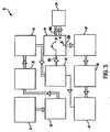
図2は、本発明の一実施形態による、温熱療法のために搬送波を生成および変調するように構成された装置10の概略図である。装置10は、4つの一次回路カードまたは回路モジュール1、2、3、4を備える。 FIG. 2 is a schematic diagram of an apparatus 10 configured to generate and modulate a carrier wave for thermotherapy, according to an embodiment of the invention. The device 10 comprises four primary circuit cards or circuit modules 1, 2, 3, 4.
カード1は、装置10の動作に特化された様々な個別の制御回路を包含する、相互接続カードである。カード1は、装置10に関わるすべての周辺機器の相互接続点である。カード1との相互接続は、複数の接続接点を有する多心ケーブルコネクタを介して行われる。カード1はモジュール式であり、保守性および/またはトラブルシューティングのため容易に置き換えられる。カード1は、表面実装電子部品およびスルーホール電子部品の両方、ならびに複数の回路相互接続プラグおよびソケットアセンブリを組み込んでいる。試験点は、試験およびトラブルシューティングのためカード1全体に慎重に配置される。カード1は、装置10に関する信頼性問題を生じる可能性のある付加的な手作業配線または接続を可能であれば排除または最低限に抑えるように設計された、多層プリント回路基板を備える。カード1はサーモスジャック接続13に接続されてもよく、これはサーモス・センサ・パッケージ17に接続されてもよい。 Card 1 is an interconnect card that includes various individual control circuits specialized for the operation of device 10. The card 1 is an interconnection point of all peripheral devices related to the device 10. Interconnection with the card 1 is performed via a multi-core cable connector having a plurality of connection contacts. The card 1 is modular and can be easily replaced for serviceability and / or troubleshooting. Card 1 incorporates both surface mount and through-hole electronic components, as well as a plurality of circuit interconnect plug and socket assemblies. Test points are carefully placed throughout the card 1 for testing and troubleshooting. The card 1 comprises a multilayer printed circuit board designed to eliminate or minimize, if possible, additional manual wiring or connections that can cause reliability problems with the device 10. The card 1 may be connected to a thermos jack connection 13, which may be connected to a thermos sensor package 17.
装置10は、主電源カードであるカード2をさらに備える。この電源は、装置10の動作に特化された回路を包含する。様々なDC電圧電位がカード2上で作り出され、カード1との相互接続は複数の導体ケーブルを通じて行われる。命令、制御、および電力は、カード1に取り付けられた取り外し可能な接点を有する複数の導体ケーブルを通じてカード2に送られる。カード2はモジュール式であり、保守性および/またはトラブルシューティングのため容易に置き換えられる。AC電源レベル電位12はカード2に直接接続し、安全を考慮して相互接続カード1を迂回している。AC電源電圧電位12は、特別に選択された組み合わせ高周波干渉フィルタ、回路遮断器/電源スイッチ14、およびユニバーサル切断可能コード接続を通じて搬送される。装置10はまた、ユニバーサルAC電圧電源で動作してもよい。 The apparatus 10 further includes a card 2 that is a main power supply card. This power supply includes circuitry specialized for the operation of the device 10. Various DC voltage potentials are created on the card 2 and the interconnection with the card 1 is made through a plurality of conductor cables. Command, control, and power are sent to the card 2 through a plurality of conductor cables with removable contacts attached to the card 1. The card 2 is modular and can be easily replaced for serviceability and / or troubleshooting. The AC power level potential 12 is directly connected to the card 2 and bypasses the interconnect card 1 for safety reasons. The AC
カード2は、装置10を動作させるために要する必要なDC電圧を作り出す。カード2上で使用される電源はモジュール形式であり、カード2自体および個々の電源のいずれも、ユーザによって、具体的には有資格または権限を有する保守技術者によって必要とされる場合には、試験および保守のため容易に置き換えられてもよい。複数のDC電圧がカード2上で作り出され、装置10の様々な回路によって使用するために必要とされるDC電源電圧を操作および/または発生させるために使用される。試験点は、試験およびトラブルシューティングのためカード2上に慎重に配置される。 The card 2 creates the necessary DC voltage required to operate the device 10. The power source used on the card 2 is modular and if both the card 2 itself and the individual power source are required by the user, specifically by a qualified or authorized service technician, It may be easily replaced for testing and maintenance. A plurality of DC voltages are created on the card 2 and used to manipulate and / or generate the DC power supply voltage required for use by the various circuits of the device 10. Test points are carefully placed on the card 2 for testing and troubleshooting.
装置10は、高周波発生および増幅モジュールである、(本明細書ではRFデッキと称されてもよい)カード3をさらに備える。カード3は、装置10に434MHz搬送波を発生させるために必要とされるRF部品を組み込んだ、専用モジュールである。カード3は、カード1に取り付けられた複数の着脱可能な接点との複数の導体ケーブル接続を介して、マスタ相互接続カード(カード1)と相互接続している。命令、制御、および電力は、複数の導体ケーブルを通じてカード3に送られる。カード3はモジュール式であり、保守性および/またはトラブルシューティングのため容易に置き換えられる。カード3によって発生した高周波エネルギーは、同軸ケーブルおよび従来型のTNCメスパネルジャック16を介して、装置10の出力接続に結合される。ジャック16は、低電力損失、アプリケータ機構(図示せず)とのインピーダンス適合の整合性、機械的整合性、および異なるアプリケータ機構に取り付けるときの使いやすさのため、カスタム選択される。 The apparatus 10 further comprises a card 3 (which may be referred to herein as an RF deck) that is a high frequency generation and amplification module. Card 3 is a dedicated module that incorporates the RF components needed to generate a 434 MHz carrier in device 10. Card 3 is interconnected with a master interconnect card (card 1) via a plurality of conductor cable connections with a plurality of removable contacts attached to card 1. Command, control, and power are sent to the card 3 through a plurality of conductor cables. The card 3 is modular and can be easily replaced for serviceability and / or troubleshooting. The high frequency energy generated by the card 3 is coupled to the output connection of the device 10 via a coaxial cable and a conventional TNC female panel jack 16. The jack 16 is custom selected for low power loss, impedance matching consistency with an applicator mechanism (not shown), mechanical consistency, and ease of use when attached to different applicator mechanisms.
装置10はデジタル制御インターフェースカードであるカード4をさらに備える。カード4は、カード1に取り付けられた複数の着脱可能な接点との複数の導体ケーブル接続を介して、マスタ相互接続カード(カード1)と接続している。命令、制御、および電力は、複数の導体ケーブルを通じてカード4に送られる。カード4はモジュール式であり、保守性および/またはトラブルシューティングのため容易に置き換えられる。カード4はまた、装置10の外表面に実装された装置タッチスクリーン制御パネル18とも直接接続している。この直接接続は、タッチスクリーン制御面に関する信頼性問題を排除するために行われる。カード4はまた、装置10の外表面上の環境的に安定したユニバーサルシリアルバス(USB)接続11との直接接続も有する。USB接続11は、装置10の修理、更新、アップグレード、または一般的なトラブルシューティングのため、保守技術者とのデジタル制御カード(カード4)の局所相互接続のために設けられる。 The device 10 further comprises a card 4 which is a digital control interface card. The card 4 is connected to the master interconnect card (card 1) via a plurality of conductor cable connections with a plurality of removable contacts attached to the card 1. Command, control, and power are sent to the card 4 through a plurality of conductor cables. The card 4 is modular and can be easily replaced for serviceability and / or troubleshooting. The card 4 is also directly connected to a device touch screen control panel 18 mounted on the outer surface of the device 10. This direct connection is made to eliminate reliability problems with the touch screen control surface. The card 4 also has a direct connection with an environmentally stable universal serial bus (USB) connection 11 on the outer surface of the device 10. The USB connection 11 is provided for local interconnection of the digital control card (card 4) with a maintenance technician for repair, update, upgrade or general troubleshooting of the device 10.
図示されないが、装置10は、ファンまたは冷媒ポンプなどの複数のモータ駆動冷却装置によって冷却される。熱は、装置のサブシステムから取り除かれて、安定した動作環境を保証するため後に装置10の内外の周囲空気と交換される、装置10の内部の気流柱に付与される。 Although not shown, the device 10 is cooled by a plurality of motor driven cooling devices such as fans or refrigerant pumps. Heat is removed from the device subsystem and applied to an airflow column inside the device 10 that is later exchanged with ambient air inside and outside the device 10 to ensure a stable operating environment.
装置10は、カード4上の装置10を収容するスーツケース内に設置された、埋め込み式全地球測位システム41をさらに含む。GPSシステムは、装置10の位置/場所を特定するデジタルマイクロプロセッサ42のメモリにメッセージを定期的に書き込むために、カード4上に収容された、デジタルマイクロプロセッサ42と協力して動作する。 The device 10 further includes an implantable global positioning system 41 installed in a suitcase that houses the device 10 on the card 4. The GPS system operates in conjunction with the digital microprocessor 42 housed on the card 4 to periodically write messages to the memory of the digital microprocessor 42 that identifies the location / location of the device 10.
装置10は、やはりカード4上の、ケース内に設置された埋め込み型セルラーモデム43をさらに含む。このセルラーモデム43システムは、多くの機能を実行するために、デジタルマイクロプロセッサ42と協力して動作する。モデム43は、たとえば装置10の位置/場所、ユーザによって使用される治療のタイプ、治療の数、およびデジタルマイクロプロセッサ42によって蓄積されたその他の関連データを含んでもよい、多数の集積データビットを報告するために、親会社と定期的に接続する。 The apparatus 10 further includes an embedded cellular modem 43 installed in the case, also on the card 4. The cellular modem 43 system operates in cooperation with the digital microprocessor 42 to perform many functions. The modem 43 reports a number of integrated data bits that may include, for example, the location / location of the device 10, the type of treatment used by the user, the number of treatments, and other relevant data stored by the digital microprocessor 42. In order to connect regularly with the parent company.
本発明の具体的実施形態において、装置10は、キャリーハンドル、ドラッグハンドル、および車輪を有する耐水性および耐久性のスーツケースの中に収容される。この耐水性スーツケースは、装置10の容器のみならず機能的搬送外殻でもある。ケースは耐候性かつ耐汚性であり、装置10の保護のみならず、電源電圧電力ケーブル、アプリケータ機構等の収納オプションも提供する。 In a specific embodiment of the invention, the device 10 is housed in a water resistant and durable suitcase having a carry handle, a drag handle, and wheels. This water-resistant suitcase is not only a container for the device 10 but also a functional transport shell. The case is weather and stain resistant and provides not only protection for the device 10, but also storage options such as power supply voltage power cable, applicator mechanism and the like.
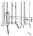
ここで図3に戻ると、RFデッキ30、すなわちカード3の部品、ならびにこれらの相互接続が、より詳細に示されている。 Returning now to FIG. 3, the RF deck 30, ie the parts of the card 3, as well as their interconnections are shown in more detail.
RFデッキ30は、434MHz RF搬送波のために安定した周波数源を作り出すように構成された、励振器31を備える。このスペクトル的に純粋なRF搬送波は、世界中の様々な通信管理局の産業科学医療用バンド要件の要件内の周波数安定性のため、励振器31の内部で自己参照される。 The RF deck 30 includes an
励振器31はまた、治療的処置の周波数変調(FM)部分も提供する。FM音声情報は、励振器31から出力される複合波形を生成するために、搬送波と混合する。励振器31の出力は、RF変調信号に関して連続的であり、デジタルコントローラカード(カード4)によって命令された通りである。音声情報は、装置10の中の複数の音声カードから生成されてもよい。音声カードは、ある範囲の変調信号を生成するように命令されることが可能な、多声デジタル制御装置である。これらの信号は、デジタルマイクロプロセッサ42(カード4に含まれる)によって、(とりわけ)振幅、周波数、波形、および単声モードか多声モードかを変化させるように、命令される。これらのカードからの音声の出力は、互いに合計または加算され、搬送波を変調するために励振器31に印加される。励振器31は、信号の出力を変更するために、減衰器32の中にその信号を出力する。 The
RFデッキ30は、減衰器32を通過した後に励振器22からの複合信号を受け付けて、ユーザによって選択された通りの意図される治療プログラムに必要とされる治療レベルまで信号を増強させるように構成された、前置増幅器33をさらに備える。可変性の電力利得は、タッチスクリーン制御パネル18上で選択された通りに、ユーザによって指定される。治療プロトコルは、低損失タイプのTNCパネル実装接続および低損失タイプの同軸ケーブルを通じてアプリケータ機構に送達される、ゼロから数十ワットの出力電力レベルを有するように、選択されてもよい。 The RF deck 30 is configured to accept the composite signal from the exciter 22 after passing through the
前置増幅器33は、終段電力増幅器34に信号を伝送する。終段電力増幅器34は、装置10の所望の治療作用に関する多くの機能を実行するように、デジタルマイクロプロセッサ41によって命令される。終段電力増幅器33は、最大または最小出力電力で動作するか静止したままのいずれかとなるように、命令される。出力電力は、ゼロ出力から最大出力まで連続的に変動可能な範囲内でレベル変化するように命令されることが可能である。終段電力増幅器33は、‘ターンオン’時間のデューティサイクル率を毎秒の動作の数学関数として‘ターンオフ’時間と関連して変動させるように、命令されることが可能である。デューティサイクル率のこの可変性は、1%の‘オン時間’と99%の‘オフ時間’から逆の99%の‘オン時間’と1%の‘オフ時間’までの範囲で、1%ずつ連続的に変動可能である。終段電力増幅器34の付加的な機能は、デジタルマイクロプロセッサ41によって命令された通りに毎秒のターンオン動作の回数を変化させることである。具体的実施形態において、パルス繰り返し率、つまり毎秒のパルス動作の範囲は、毎秒半分の動作(0.5Hz)から毎秒5000回超の動作(5KHz)まで変動可能である。可変出力電力、毎秒の可変パルス繰り返し、および可変パルス幅比デューティサイクルの、この複数の組み合わせは、ユーザによって選択された通りに、生物にとって広範な治療および緩和処置の選択肢を作り出す。 The preamplifier 33 transmits a signal to the final stage power amplifier 34. Final power amplifier 34 is commanded by digital microprocessor 41 to perform a number of functions related to the desired therapeutic action of device 10. The final stage power amplifier 33 is commanded to either operate at maximum or minimum output power or remain stationary. The output power can be commanded to level change within a continuously variable range from zero output to maximum output. The final stage power amplifier 33 can be commanded to vary the duty cycle rate of the 'turn-on' time in relation to the 'turn-off' time as a mathematical function of operation per second. This variability of the duty cycle rate ranges from 1% 'on time' and 99% 'off time' to reverse 99% 'on time' and 1% 'off time' by 1%. Continuously variable. An additional function of the final power amplifier 34 is to change the number of turn-on operations per second as commanded by the digital microprocessor 41. In a specific embodiment, the pulse repetition rate, ie, the range of pulse operations per second, can vary from half operation per second (0.5 Hz) to more than 5000 operations per second (5 KHz). This multiple combination of variable output power, variable pulse repetitions per second, and variable pulse width ratio duty cycle creates a wide range of therapeutic and palliative treatment options for the organism as selected by the user.
RFデッキ30は、方向性カプラ35をさらに備える。方向性カプラ35は、終段電力増幅器34の出力電力を感知し、この振幅関連情報をデジタルマイクロプロセッサ41に送信する。これは、使用のために選択された治療プロトコルにしたがって終段電力増幅器34が動作していることを保証するための、抑制と均衡による安全機構である。方向性カプラ35はまた、アプリケータ機構からのいかなる未使用RFエネルギーも感知する。いかなる未使用エネルギーも、VSWRの用語で損失として表現される。VSWRは、順方向エネルギーと反射または未使用の全エネルギーとの比である。整合性の式は1:1.00である。整合性から1:3.00の量に向かう逸脱は、望ましい動作条件ではない。アプリケータ機構によって使用されないかまたは装置10に向かって‘反射’されるエネルギーは、終段電力増幅器34に損傷を招く可能性がある。 The RF deck 30 further includes a directional coupler 35. The directional coupler 35 senses the output power of the final stage power amplifier 34 and transmits this amplitude related information to the digital microprocessor 41. This is a restrained and balanced safety mechanism to ensure that the final power amplifier 34 is operating according to the treatment protocol selected for use. Directional coupler 35 also senses any unused RF energy from the applicator mechanism. Any unused energy is expressed as a loss in VSWR terminology. VSWR is the ratio of forward energy to total reflected or unused energy. The consistency formula is 1: 1.00. Deviation from consistency to an amount of 1: 3.00 is not a desirable operating condition. Energy that is not used by the applicator mechanism or 'reflected' towards the device 10 may cause damage to the final power amplifier 34.
RFデッキ30は、高周波信号に出入りさせるように構成された絶縁器/循環器36を、さらに備える。絶縁器/循環器36は、アプリケータ機構の誤適用またはアプリケータ機構の故障による電気的損傷から終段電力増幅器34を保護する機能を有する、一方通行の安全経路として機能する。絶縁器/循環器36は、これに関連づけられた3つのRF接続を備える。方向性カプラ35を介して終段電力増幅器34からのRFエネルギーは、ポート301から絶縁器/循環器36に入力する。環状交差点と類似の動作が、時計回りのロータリーの運動として行われる。この運動は、ポート301からの印加されたRFエネルギーを最小限の損失でポート302を通じて絶縁器/循環器36から出力させる。完全条件において、ポート302から出力するエネルギーのほぼ100%が、搬送波出力接続39を通じて接続されたアプリケータ機構(図示せず)によって消費され、生物に付与される。この完全条件は滅多に起こらないので、VSWR(電圧定在波比(Voltage To Standing Wave Ratio)、下記参照)として表されるこの未使用エネルギーは、絶縁器/循環器36に戻るように反射される。この反射エネルギーはポート302から絶縁器/循環器36に再入力し、環状交差点の時計回り運動でポート303(したがって用語絶縁器/循環器36)から絶縁器/循環器36を出る。ポート303は、反射してポート302に入力したエネルギーがポート303を介して絶縁器/循環器36を出られるようにすることしかできない、一方向ポータルである。ポート303から放出されたエネルギーは、拒絶減衰器37として知られる抵抗装置に向かって短絡される。 The RF deck 30 further includes an insulator / circulator 36 configured to enter and exit high frequency signals. The insulator / circulator 36 functions as a one-way safety path having the function of protecting the final power amplifier 34 from electrical damage due to misapplication of the applicator mechanism or failure of the applicator mechanism. The insulator / circulator 36 has three RF connections associated with it. RF energy from the final stage power amplifier 34 is input from the port 301 to the insulator / circulator 36 via the directional coupler 35. An operation similar to a roundabout is performed as a clockwise rotary movement. This movement causes the applied RF energy from port 301 to be output from insulator / circulator 36 through
拒絶減衰器37は、入力および出力を有する2ポート装置である。拒絶減衰器37は、拒絶減衰器37の入力ポートに誘導されたいかなるレベルの電力も低下(すなわち減衰)させ、拒絶減衰器37の出力ポートから低値画像の電力を出力させる。RF信号は、小型電子回路によって直流(DC)方式に変換される。結果的に得られるDCエネルギーもまた、434MHz搬送波信号と生物との結合の効率の値を測定または推定する代替手段としてのデジタルマイクロプロセッサ42に供給される。この結果的なDC値は、アプリケータ機構と生物との結合の効率の表示を駆動するために使用されてもよく、タッチスクリーンデジタルディスプレイ18上に配置されてもよい。 The rejection attenuator 37 is a two-port device having an input and an output. The rejection attenuator 37 reduces (that is, attenuates) any level of power induced at the input port of the rejection attenuator 37, and outputs low-value image power from the output port of the rejection attenuator 37. The RF signal is converted to a direct current (DC) system by a small electronic circuit. The resulting DC energy is also provided to the digital microprocessor 42 as an alternative means of measuring or estimating the value of the coupling efficiency between the 434 MHz carrier signal and the organism. This resulting DC value may be used to drive an indication of the efficiency of the applicator mechanism's association with the organism and may be placed on the touch screen digital display 18.
デジタルマイクロプロセッサ42の安全特性として、VSWRが1:1.30に近づくと、アプリケータ機構に送達される増幅器出力電力は、生物にとって安全であり、前置増幅器33および終段電力増幅器34の電気的整合性にとっても安全なレベルまで、低下する。ユーザへの支援として、タッチスクリーン制御パネル18上に効率表示がある。アプリケータ機構が不適切に生物に印加された場合、効率表示はたとえば緑色から黄色に変わってもよく、結合の効率が悪化し続けた場合、効率表示は黄色から赤色に変わってもよい。 As a safety characteristic of the digital microprocessor 42, when the VSWR approaches 1: 1.30, the amplifier output power delivered to the applicator mechanism is safe for the organism and the electrical power of the preamplifier 33 and the final power amplifier 34 is To a level that is safe for global consistency. As an aid to the user, there is an efficiency display on the touch screen control panel 18. If the applicator mechanism is improperly applied to the organism, the efficiency display may change from green to yellow, for example, and if the efficiency of binding continues to deteriorate, the efficiency display may change from yellow to red.
RFデッキ30は、拒絶負荷減衰器38をさらに備える。拒絶負荷減衰器38は、ACまたはDC信号あるいは両方の組み合わせを受け付けて、一般的にデシベル(dB)で表される対数率のエネルギー量を低下させる、2ポート装置である。拒絶負荷減衰器38は、搬送波と生物との結合におけるアプリケータ機構の効率の表示を展開するために、DC電圧レベルをデジタルマイクロプロセッサ42に供給するための安全機構として、使用される。その減衰機能を実行するために、熱を発生し、これを放散させなければならない。この熱放散は、拒絶負荷減衰器38をヒートシンクに取り付けることによって実現される。 The RF deck 30 further includes a reject load attenuator 38. The reject load attenuator 38 is a two-port device that accepts an AC or DC signal or a combination of both and reduces the amount of logarithmic energy, typically expressed in decibels (dB). The reject load attenuator 38 is used as a safety mechanism for supplying a DC voltage level to the digital microprocessor 42 to develop an indication of the efficiency of the applicator mechanism in coupling the carrier and the organism. In order to perform its attenuation function, heat must be generated and dissipated. This heat dissipation is achieved by attaching a reject load attenuator 38 to the heat sink.
ここで図4に戻ると、本発明の一実施形態によるアプリケータ機構50が示されている。アプリケータ機構50は、適切な手段を介して(たとえば、切断可能な同軸ケーブルを介して)装置10に接続されてもよく、温熱療法を提供するように、変調した搬送波を生物に送達するように構成されている。 Returning now to FIG. 4, an applicator mechanism 50 according to one embodiment of the present invention is shown. The applicator mechanism 50 may be connected to the device 10 via suitable means (eg, via a severable coaxial cable) to deliver the modulated carrier to the organism so as to provide thermotherapy. It is configured.
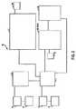
アプリケータ機構50は:前部外カバー51、第一誘電体層52、スロットアンテナ53、第二誘電体層54、マイクロストリップアンテナ55、第三誘電体層66、バッキング57、および後部外カバー58をこの順で含む、多層構造を備える。各層の詳細は、図5から図14に示されている。異なる相は、いくつかの方法で相互作用する。 Applicator mechanism 50 includes: front outer cover 51, first dielectric layer 52, slot antenna 53, second dielectric layer 54, microstrip antenna 55, third dielectric layer 66, backing 57, and rear outer cover 58. Are provided in this order. Details of each layer are shown in FIGS. Different phases interact in several ways.
図5は、前部外カバー51の図である。前部外カバーは、温熱療法を受けている生物の標的領域に、またはその近傍に適用されるように、設計されている。前部外カバーは、ポリウレタン繊維またはその他いずれかの可撓性材料で作られることが可能である。この実施形態において、これは2つのポート、すなわち同軸ケーブルポート511および温度センサケーブルポート512を含む。 FIG. 5 is a view of the front outer cover 51. The front outer cover is designed to be applied at or near the target area of the organism undergoing thermotherapy. The front outer cover can be made of polyurethane fiber or any other flexible material. In this embodiment, this includes two ports: a
図6は、内蔵型マイクロチップを有する温度センサをその中に受容するための開口521を備える、第一誘電体層52の図である。温度計は、治療の送達中に生物の体温測定ができるようにする。第一誘電体層52は、シリコーンまたはその他いずれかの絶縁材料から作られることが可能であり、約1.5mmの厚さを有することができる。一実施形態において、誘電体層52の誘電率はおよそ2.9である。 FIG. 6 is a diagram of a first dielectric layer 52 with an
図7は、第一誘電体層52の下にあるスロットアンテナ53の図である。アプリケータ機構50が装置10に接続されたとき、装置10によって発生した変調搬送波は、生物に変調搬送波を送達するためにスロットアンテナ53に伝送される。スロットアンテナ53は、スロットアンテナ53から放射された変調搬送波を集中させるための2つのマイクロ波レンズ531、532を備える。2つのマイクロ波レンズ531、532は、互いにもスロットアンテナ53とも接触しない。スロットアンテナ53は、およそ0.5mmの厚さを有する平坦な可撓性回路材料から作られることが可能である。スロットアンテナ53は、温度IC533、温度ICとマイクロコントローラ581との間の第一コネクタ534、温度IC533と外部電力およびデータ源(図示せず)との間の第二コネクタ535、金属支持板536、および接地溶接部を通すためのスロット537を、さらに備える。図8は、第二誘電体層54と接するスロットアンテナ53の反対側の図である。 FIG. 7 is a view of the slot antenna 53 under the first dielectric layer 52. When the applicator mechanism 50 is connected to the device 10, the modulated carrier wave generated by the device 10 is transmitted to the slot antenna 53 to deliver the modulated carrier wave to the organism. The slot antenna 53 includes two
図9は、第二誘電体層54を示す。第一誘電体層52とともに、これはマイクロストリップアンテナ55からスロットアンテナ53を電気的に絶縁するのに役立つ。第二誘電体層54は、シリコーンまたは2.9の誘電率を有するその他いずれかの絶縁材料から作られることが可能である。これは約1.5mmの厚さを有することができる。 FIG. 9 shows the second dielectric layer 54. Together with the first dielectric layer 52, this serves to electrically isolate the slot antenna 53 from the microstrip antenna 55. The second dielectric layer 54 can be made from silicone or any other insulating material having a dielectric constant of 2.9. This can have a thickness of about 1.5 mm.
図10は、マイクロストリップアンテナ55の、第二誘電体層54に対向する側を示す。マイクロストリップアンテナは、接地線を通してマイクロコントローラ581に接続させるためのスロット551を含む。スロット551は接地リム551aによって包囲されている。これはまた、Z字型の切り抜き552も有している。マイクロストリップアンテナ55の角はエポキシを用いて他の層に接合されている。図11は、第三誘電体層56と接する、マイクロストリップアンテナ55の反対側を示しており、これはマイクロストリップアンテナ55の溶接側である。接地のための銅製延長クリップはスロットアンテナ53までずっと、スロット551に接続されている。マイクロストリップアンテナ55は、銅製延長クリップ553および銅製接続クリップ554をさらに備える。 FIG. 10 shows the side of the microstrip antenna 55 that faces the second dielectric layer 54. The microstrip antenna includes a
図12は、第三誘電体層56を示す。第三誘電体層54は、シリコーンまたは2.9の誘電率を有するその他いずれかの絶縁材料から作られることが可能である。これは約1.5mmの厚さを有することができる。マイクロストリップアンテナ55をマイクロコントローラ581に接続するための同軸リード線および接地用のスロット561がある。リード専用の第一スロット561の上に位置するさらに小さいスロット562がある。 FIG. 12 shows the third dielectric layer 56. The third dielectric layer 54 can be made from silicone or any other insulating material having a dielectric constant of 2.9. This can have a thickness of about 1.5 mm. There is a coaxial lead and
図13は、バッキング57を示す。バッキング57は、ネオプレンなど、ウェットスーツと類似の材料から作られることが可能である。材料は、20.1の好適な誘電率を有する。バッキング57は、左下のおよそ40%が、右下よりもおよそ9%長いという点において、長方形ではない。これは、ケーブル接地のためにさらなる遮蔽を提供するためである。 FIG. 13 shows the backing 57. The backing 57 can be made from a material similar to a wetsuit, such as neoprene. The material has a suitable dielectric constant of 20.1. The backing 57 is not rectangular in that approximately 40% in the lower left is approximately 9% longer than the lower right. This is to provide additional shielding for cable grounding.
図14は、外部ケーシング58の後部を示す。外部ケーシングには、マイクロプロセッサ581が取り付けられている。マイクロプロセッサ581には、電力入力582、温度ICへの電力出力534、および接地583の3つのケーブルが取り付けられている。すべての層はアンテナアセンブリの上に密接に縫い付けられている。 FIG. 14 shows the rear part of the outer casing 58. A microprocessor 581 is attached to the outer casing. The microprocessor 581 is attached with three cables: a power input 582, a
アプリケータ機構50は、一旦その使用寿命に到達したらスロットアンテナ53を自動的に無効化する回路を含む。アプリケータ機構50は、スロットアンテナ53に引き込まれその中を通る通電電流の流れを制御する、エネルギー遮断回路(図示せず)を組み込んでいる。エネルギー遮断回路は、スロットアンテナ53の使用度合いを計算するマイクロチップを通じて起動され、一旦最大使用に到達したらスロットアンテナ53への電力を永久に遮断する。 Applicator mechanism 50 includes circuitry that automatically disables slot antenna 53 once its useful life has been reached. The applicator mechanism 50 incorporates an energy cutoff circuit (not shown) that is drawn into the slot antenna 53 and controls the flow of energized current therethrough. The energy cut-off circuit is activated through a microchip that calculates the usage degree of the slot antenna 53, and once the maximum use is reached, the power to the slot antenna 53 is cut off permanently.
マイクロチップは、使用されるたびにスロットアンテナ53の実使用時間を測定し、マイクロチップ回路に内蔵またはプログラムされた永久カウンタにその時間を加算することによって、スロットアンテナ53の合計使用時間を測定することができる。永久カウンタによって測定された累積使用時間が予め設定された制限に到達すると、エネルギー遮断回路が起動され、スロットアンテナ53は永久に無効化される。あるいは、マイクロチップはスロットアンテナ53のオン/オフサイクル数を単純に測定することができ、事前に設定されたサイクル制限の閾値に一旦到達したら、エネルギー遮断回路が起動されてスロットアンテナ53は永久に無効化される。アンテナの使用寿命を測定するその他の方法は、当業者によって容易に想起可能であり、言及されたマイクロチップの論理に組み込まれることが可能である。 Each time the microchip is used, the actual usage time of the slot antenna 53 is measured, and the total usage time of the slot antenna 53 is measured by adding the time to a permanent counter built in or programmed in the microchip circuit. be able to. When the accumulated usage time measured by the permanent counter reaches a preset limit, the energy cutoff circuit is activated and the slot antenna 53 is permanently disabled. Alternatively, the microchip can simply measure the number of on / off cycles of the slot antenna 53, and once the preset cycle limit threshold is reached, the energy shut-off circuit is activated and the slot antenna 53 becomes permanent. It is invalidated. Other methods of measuring antenna service life can be easily recalled by those skilled in the art and can be incorporated into the logic of the mentioned microchip.
スロットアンテナ53が一旦無効化されると、マイクロチップ回路は、スロットアンテナ53がその使用寿命を超過しており交換されるべきであることを示すために、操作者への聴覚または視覚信号を選択的に生成することができる。やはり選択的に、マイクロチップは、寿命が近づくにつれて操作者に視覚的な合図を提供することもできる。たとえば、操作者は、残り寿命のカウントダウンまたは表示、あるいは装置の動作サイクル数を見せられてもよい。あるいは、操作者は単純に、どのくらいの時間または何回のサイクル数がスロットアンテナ53に残されているかを示すために、異なる色の光、または特定数の光を見せられてもよい。 Once slot antenna 53 is disabled, the microchip circuit selects an audio or visual signal to the operator to indicate that slot antenna 53 has exceeded its service life and should be replaced. Can be generated automatically. Again, optionally, the microchip can provide a visual cue to the operator as it approaches its end of life. For example, the operator may be shown a countdown or display of remaining life, or the number of operating cycles of the device. Alternatively, the operator may simply be shown a different color light or a specific number of lights to indicate how much time or how many cycles are left in the slot antenna 53.
本発明は特定の実施形態に関連して記載されてきたものの、本発明はこれらの実施形態に限定されないこと、ならびに本発明の範囲から逸脱することなくこれら実施形態の代替例、修正例、および変形例が当業者によって実行されてもよいことは、理解されるべきである。 Although the invention has been described with reference to particular embodiments, the invention is not limited to these embodiments, and alternatives, modifications, and variations of these embodiments without departing from the scope of the invention. It should be understood that variations may be performed by those skilled in the art.
Claims (30)
Translated fromJapanese搬送波信号を発生するように構成された信号発生器と、
変調信号を用いて前記搬送波信号を選択的に変調するように構成された信号変調器と、
前記変調した搬送波信号を前記生物の標的箇所に送達するように構成された放射体と、
を備える装置。A device for providing thermotherapy to an organism,
A signal generator configured to generate a carrier signal;
A signal modulator configured to selectively modulate the carrier signal using a modulation signal;
A radiator configured to deliver the modulated carrier signal to a target location of the organism;
A device comprising:
前記監視される使用パラメータが所定の閾値に到達したときに前記放射体のさらなる使用を自動的に防止するように構成された遮断装置と、
をさらに備える、請求項1に記載の装置。A usage monitor configured to monitor usage parameters of the radiator;
A shut-off device configured to automatically prevent further use of the radiator when the monitored usage parameter reaches a predetermined threshold;
The apparatus of claim 1, further comprising:
搬送波信号を生成するステップと、
変調信号を用いて前記搬送波信号を選択的に変調するステップと、
前記変調した搬送波信号を前記生物の標的箇所に送達するステップと、
を備える方法。A method of providing thermotherapy to an organism,
Generating a carrier wave signal;
Selectively modulating the carrier signal with a modulation signal;
Delivering the modulated carrier signal to a target location of the organism;
A method comprising:
前記生物の標的箇所に信号を送達するように構成された放射体と、
前記放射体の使用パラメータを監視するように構成された使用モニタと、
前記監視される使用パラメータが所定の閾値に到達したときに前記放射体のさらなる使用を自動的に防止するように構成された遮断装置と、
を備える装置。A device for providing thermotherapy to an organism,
A radiator configured to deliver a signal to a target location of the organism;
A usage monitor configured to monitor usage parameters of the radiator;
A shut-off device configured to automatically prevent further use of the radiator when the monitored usage parameter reaches a predetermined threshold;
A device comprising:
前記生物の標的箇所に信号を放射するステップと、
前記放射体の使用パラメータを監視するステップと、
前記監視される使用パラメータが所定の閾値に到達したときに前記放射体のさらなる使用を自動的に防止するステップと、
を備える方法。A method of providing thermotherapy to an organism,
Emitting a signal to a target site of the organism;
Monitoring usage parameters of the radiator;
Automatically preventing further use of the radiator when the monitored usage parameter reaches a predetermined threshold;
A method comprising:
Applications Claiming Priority (5)
| Application Number | Priority Date | Filing Date | Title |
|---|---|---|---|
| US201462049802P | 2014-09-12 | 2014-09-12 | |
| US62/049,802 | 2014-09-12 | ||
| GB1506851.3AGB2531619A (en) | 2014-09-12 | 2015-04-22 | Apparatus and method for providing hyperthermia therapy |
| GB1506851.3 | 2015-04-22 | ||
| PCT/US2015/049787WO2016040867A1 (en) | 2014-09-12 | 2015-09-11 | Apparatus and method for providing hyperthermia therapy |
Publications (2)
| Publication Number | Publication Date |
|---|---|
| JP2017528293Atrue JP2017528293A (en) | 2017-09-28 |
| JP2017528293A5 JP2017528293A5 (en) | 2018-10-25 |
Family
ID=53299002
Family Applications (1)
| Application Number | Title | Priority Date | Filing Date |
|---|---|---|---|
| JP2017533718APendingJP2017528293A (en) | 2014-09-12 | 2015-09-11 | Apparatus and method for providing hyperthermia |
Country Status (12)
| Country | Link |
|---|---|
| US (1) | US11324961B2 (en) |
| EP (1) | EP3191182B1 (en) |
| JP (1) | JP2017528293A (en) |
| CN (1) | CN107206247A (en) |
| AU (2) | AU2015314743A1 (en) |
| DK (1) | DK3191182T3 (en) |
| ES (1) | ES2858675T3 (en) |
| GB (1) | GB2531619A (en) |
| HU (1) | HUE053551T2 (en) |
| MX (1) | MX2017003287A (en) |
| PL (1) | PL3191182T3 (en) |
| WO (1) | WO2016040867A1 (en) |
Families Citing this family (11)
| Publication number | Priority date | Publication date | Assignee | Title |
|---|---|---|---|---|
| US10232188B2 (en)* | 2011-11-04 | 2019-03-19 | Thermofield Inc. | Single cable apparatus and method for hyperthermic treatments |
| EP3231478A1 (en)* | 2016-04-13 | 2017-10-18 | Oncotherm Kft. | Radiofrequency hyperthermia device with double impedance matching system |
| US9913981B1 (en)* | 2016-09-03 | 2018-03-13 | Ohh-Med Medical Ltd. | Methods and devices for treating erectile dysfunction |
| JP2020503111A (en)* | 2016-12-27 | 2020-01-30 | アヴェント インコーポレイテッド | Articles and methods for treating diabetic peripheral neuropathy |
| WO2019121911A1 (en)* | 2017-12-19 | 2019-06-27 | Innovarius Ltd. | Apparatus and method for creating resonant standing waves in biological tissue |
| WO2019121910A1 (en)* | 2017-12-19 | 2019-06-27 | Innovarius Ltd. | Apparatus and method for creating resonant standing waves in biological tissue |
| WO2019121909A1 (en)* | 2017-12-19 | 2019-06-27 | Innovarius Ltd. | Apparatus for creating resonant standing waves in biological tissue |
| WO2019121913A1 (en)* | 2017-12-19 | 2019-06-27 | Innovarius Ltd. | Apparatus for creating resonant standing waves in biological tissue |
| WO2019121907A1 (en)* | 2017-12-19 | 2019-06-27 | Innovarius Ltd. | Apparatus and method for creating resonant standing waves in biological tissue |
| WO2019121914A1 (en)* | 2017-12-19 | 2019-06-27 | Innovarius Ltd | Apparatus for creating resonant standing waves in biological tissue |
| WO2019121905A1 (en)* | 2017-12-19 | 2019-06-27 | Innovarius Ltd. | Apparatus for creating resonant standing waves in biological tissue |
Citations (3)
| Publication number | Priority date | Publication date | Assignee | Title |
|---|---|---|---|---|
| JPS57157164A (en)* | 1981-03-25 | 1982-09-28 | Nippon Telegr & Teleph Corp <Ntt> | Testing method for reliability in thermo-acceleration of integrated circuit |
| JP2007536016A (en)* | 2004-05-07 | 2007-12-13 | サーム メッド エルエルシー | Enhanced system and method for RF guided hyperthermia |
| JP2012515604A (en)* | 2009-01-23 | 2012-07-12 | ドン ハン カン | Skin treatment device |
Family Cites Families (46)
| Publication number | Priority date | Publication date | Assignee | Title |
|---|---|---|---|---|
| US3676633A (en)* | 1970-02-24 | 1972-07-11 | Adm Tronics | Electronic trimming of microelectronic resistors |
| US3617684A (en)* | 1970-02-24 | 1971-11-02 | Datapax Computer Systems Corp | Electronic trimming of microelectronic resistors |
| DE3490016T1 (en)* | 1983-01-21 | 1985-02-07 | Ramm Associates, Creve Coeur, Mo. | Implantable hyperthermia device and system |
| US4667677A (en)* | 1986-04-28 | 1987-05-26 | Adm Tronics Unlimited, Inc. | Corona discharge thermotherapy technique |
| US5190037A (en)* | 1991-10-21 | 1993-03-02 | Adm Tronics Unlimited, Inc. | High-power corona discharge beam thermotherapy system |
| US5983141A (en)* | 1996-06-27 | 1999-11-09 | Radionics, Inc. | Method and apparatus for altering neural tissue function |
| US6246912B1 (en)* | 1996-06-27 | 2001-06-12 | Sherwood Services Ag | Modulated high frequency tissue modification |
| AT407480B (en)* | 1997-05-06 | 2001-03-26 | Macher David | HEATING DEVICE FOR HEATING A SKIN SURFACE OR PARTIAL AREAS OF A HUMAN BODY |
| USRE40279E1 (en)* | 1997-06-26 | 2008-04-29 | Sherwood Services Ag | Method and system for neural tissue modification |
| US6308089B1 (en) | 1999-04-14 | 2001-10-23 | O.B. Scientific, Inc. | Limited use medical probe |
| US6840955B2 (en)* | 2000-01-27 | 2005-01-11 | Robert J. Ein | Therapeutic apparatus |
| JP2004520865A (en)* | 2000-07-25 | 2004-07-15 | リタ メディカル システムズ インコーポレイテッド | Apparatus for tumor detection and treatment using localized impedance measurements |
| US6673063B2 (en) | 2000-10-06 | 2004-01-06 | Expanding Concepts, Llc. | Epidural thermal posterior annuloplasty |
| JP4450622B2 (en)* | 2001-09-28 | 2010-04-14 | アンジオ ダイナミクス インコーポレイテッド | Impedance-controlled tissue peeling device and method |
| US8348936B2 (en) | 2002-12-09 | 2013-01-08 | The Trustees Of Dartmouth College | Thermal treatment systems with acoustic monitoring, and associated methods |
| US20050015125A1 (en)* | 2003-03-14 | 2005-01-20 | Mioduski Paul C. | Hyperthermia treatment systems and methods |
| US6904323B2 (en)* | 2003-05-14 | 2005-06-07 | Duke University | Non-invasive apparatus and method for providing RF energy-induced localized hyperthermia |
| US20100161010A1 (en)* | 2003-12-11 | 2010-06-24 | Thomas David A | Perceptible Apparatus and Methods for Reactive Effect |
| US7510555B2 (en)* | 2004-05-07 | 2009-03-31 | Therm Med, Llc | Enhanced systems and methods for RF-induced hyperthermia |
| US20070250139A1 (en)* | 2004-05-07 | 2007-10-25 | John Kanzius | Enhanced systems and methods for RF-induced hyperthermia II |
| US20050283148A1 (en)* | 2004-06-17 | 2005-12-22 | Janssen William M | Ablation apparatus and system to limit nerve conduction |
| US20070093802A1 (en)* | 2005-10-21 | 2007-04-26 | Danek Christopher J | Energy delivery devices and methods |
| CN1657116A (en)* | 2004-11-22 | 2005-08-24 | 孙映辉 | Microwave warmer for whole body |
| US20060265034A1 (en) | 2005-04-05 | 2006-11-23 | Ams Medical Sa | Microwave devices for treating biological samples and tissue and methods for using same |
| US8734438B2 (en)* | 2005-10-21 | 2014-05-27 | Covidien Ag | Circuit and method for reducing stored energy in an electrosurgical generator |
| US7559945B2 (en)* | 2006-01-13 | 2009-07-14 | Clarimedix Inc. | Multi-spectral photon therapy device and methods of use |
| US20070249938A1 (en)* | 2006-04-20 | 2007-10-25 | Donald J. Shields | Systems, devices, and methods employing therapeutic ultrasound of living tissues |
| KR100739002B1 (en)* | 2006-04-28 | 2007-07-12 | (주) 태웅메디칼 | Multi RF Generator for High Frequency Thermal Therapy |
| US20130046357A1 (en)* | 2008-03-27 | 2013-02-21 | Joseph Neev | Tissue or nerve treatment device and method |
| US20090036938A1 (en)* | 2007-07-30 | 2009-02-05 | Cardiac Pacemakers, Inc. | Method and system for external counterpulsation therapy |
| US20090122583A1 (en)* | 2007-11-13 | 2009-05-14 | Bruce Gelerter | Corona discharge apparatus |
| US20090254008A1 (en)* | 2008-01-29 | 2009-10-08 | Shields Jr Donald J | Systems, devices, and methods to concurrently deliver ultrasound waves having thermal and non-thermal effects |
| US8652184B2 (en)* | 2008-08-22 | 2014-02-18 | James E. Bare | Resonant frequency device |
| EP2174689A1 (en)* | 2008-10-13 | 2010-04-14 | Oncotherm Kft. | Radiofrequency hyperthermia device with target feedback signal modulation |
| US20110276113A1 (en)* | 2010-04-12 | 2011-11-10 | Cybulski James S | RF Tissue Modulation Devices and Methods of Using the Same |
| US8494604B2 (en)* | 2009-09-21 | 2013-07-23 | Covidien Lp | Wavelength-division multiplexing in a multi-wavelength photon density wave system |
| US10716940B2 (en)* | 2009-10-20 | 2020-07-21 | Nyxoah SA | Implant unit for modulation of small diameter nerves |
| US8391943B2 (en)* | 2010-03-31 | 2013-03-05 | Covidien Lp | Multi-wavelength photon density wave system using an optical switch |
| US8690748B1 (en)* | 2010-08-02 | 2014-04-08 | Chi Yung Fu | Apparatus for measurement and treatment of a patient |
| JP6580298B2 (en)* | 2010-12-16 | 2019-09-25 | サイオン・ニューロスティム,リミテッド・ライアビリティ・カンパニー | Vestibular stimulation device and vestibular stimulation system |
| WO2012092057A1 (en)* | 2010-12-29 | 2012-07-05 | Ethicon Endo-Surgery, Inc. | Methods and devices for activating brown adipose tissue with light |
| US20150105701A1 (en)* | 2013-08-22 | 2015-04-16 | Energize Medical Llc | Therapeutic energy systems |
| EP2703042A1 (en)* | 2012-08-27 | 2014-03-05 | XAX Kft. | RF hyperthermia device for personalized treatment and diagnosis |
| EP2950711A4 (en)* | 2013-01-31 | 2016-09-21 | Univ Ramot | DETECTION, DIAGNOSIS AND MONITORING OF OSTEOPOROSIS BY A PHOTOACOUSTIC PROCESS |
| WO2014146082A1 (en)* | 2013-03-15 | 2014-09-18 | Bhl Patent Holdings Llc | Materials and methods for treating neuropathies and related disorders including those involving a keystone nerve |
| US10038408B2 (en)* | 2015-06-26 | 2018-07-31 | Cactus Semiconductor, Inc. | Pseudo-random chopper amplifier |
- 2015
- 2015-04-22GBGB1506851.3Apatent/GB2531619A/ennot_activeWithdrawn
- 2015-09-11MXMX2017003287Apatent/MX2017003287A/enunknown
- 2015-09-11AUAU2015314743Apatent/AU2015314743A1/ennot_activeAbandoned
- 2015-09-11WOPCT/US2015/049787patent/WO2016040867A1/enactiveApplication Filing
- 2015-09-11USUS14/851,928patent/US11324961B2/enactiveActive
- 2015-09-11JPJP2017533718Apatent/JP2017528293A/enactivePending
- 2015-09-11PLPL15839805Tpatent/PL3191182T3/enunknown
- 2015-09-11EPEP15839805.7Apatent/EP3191182B1/enactiveActive
- 2015-09-11HUHUE15839805Apatent/HUE053551T2/enunknown
- 2015-09-11ESES15839805Tpatent/ES2858675T3/enactiveActive
- 2015-09-11DKDK15839805.7Tpatent/DK3191182T3/enactive
- 2015-09-11CNCN201580058158.7Apatent/CN107206247A/enactivePending
- 2020
- 2020-06-11AUAU2020203861Apatent/AU2020203861B2/enactiveActive
Patent Citations (3)
| Publication number | Priority date | Publication date | Assignee | Title |
|---|---|---|---|---|
| JPS57157164A (en)* | 1981-03-25 | 1982-09-28 | Nippon Telegr & Teleph Corp <Ntt> | Testing method for reliability in thermo-acceleration of integrated circuit |
| JP2007536016A (en)* | 2004-05-07 | 2007-12-13 | サーム メッド エルエルシー | Enhanced system and method for RF guided hyperthermia |
| JP2012515604A (en)* | 2009-01-23 | 2012-07-12 | ドン ハン カン | Skin treatment device |
Also Published As
| Publication number | Publication date |
|---|---|
| CN107206247A (en) | 2017-09-26 |
| EP3191182B1 (en) | 2021-01-20 |
| PL3191182T3 (en) | 2021-10-25 |
| DK3191182T3 (en) | 2021-03-08 |
| US11324961B2 (en) | 2022-05-10 |
| HUE053551T2 (en) | 2021-07-28 |
| EP3191182A4 (en) | 2019-01-09 |
| MX2017003287A (en) | 2018-08-01 |
| WO2016040867A1 (en) | 2016-03-17 |
| US20160074668A1 (en) | 2016-03-17 |
| ES2858675T3 (en) | 2021-09-30 |
| GB2531619A (en) | 2016-04-27 |
| AU2020203861A1 (en) | 2020-07-02 |
| EP3191182A1 (en) | 2017-07-19 |
| AU2015314743A1 (en) | 2017-04-27 |
| AU2020203861B2 (en) | 2021-09-23 |
| GB201506851D0 (en) | 2015-06-03 |
Similar Documents
| Publication | Publication Date | Title |
|---|---|---|
| AU2020203861B2 (en) | Apparatus and method for providing hyperthermia therapy | |
| ES2967293T3 (en) | Devices for the aesthetic treatment of biological structures using radiofrequency and magnetic energy | |
| CN103096976B (en) | Portable ultrasound system | |
| US20140222102A1 (en) | Smart phone application for providing neuro/muscular electro-stimulation | |
| US10953235B2 (en) | Systems and methods for targeted deep hyperthermia by time-shared RF inductive applicators | |
| US10232188B2 (en) | Single cable apparatus and method for hyperthermic treatments | |
| CA2945350A1 (en) | Electromagnetic therapy device and methods | |
| US12064392B2 (en) | Module and device for emitting electromagnetic waves | |
| US7305264B2 (en) | Bone cancer pain management utilizing ultrasound | |
| KR101396285B1 (en) | Low-intensity Ultrasonic Medical Treatment Equipment for Arthritis | |
| JP2012518486A (en) | Electric muscle stimulation system and method using energy induction area | |
| US9669231B1 (en) | Apparatus and method for hyperthermic treatments | |
| KR20060008291A (en) | Electromagnetic Therapy Device and Method | |
| US6136020A (en) | Treatment for prostatitis and apparatus therefor | |
| US20120116274A1 (en) | Remote unattended low level light therapy orthopedic device, wearing means and method of use | |
| KR20200055055A (en) | Electromagnetic wave transmission device | |
| KR20180117362A (en) | Apparatus and Method for Hyperthermia Treatment by using a current feedback | |
| KR101968304B1 (en) | A high frequency cancer treatment |
Legal Events
| Date | Code | Title | Description |
|---|---|---|---|
| A521 | Request for written amendment filed | Free format text:JAPANESE INTERMEDIATE CODE: A523 Effective date:20180911 | |
| A621 | Written request for application examination | Free format text:JAPANESE INTERMEDIATE CODE: A621 Effective date:20180911 | |
| A977 | Report on retrieval | Free format text:JAPANESE INTERMEDIATE CODE: A971007 Effective date:20190719 | |
| A131 | Notification of reasons for refusal | Free format text:JAPANESE INTERMEDIATE CODE: A131 Effective date:20190730 | |
| A601 | Written request for extension of time | Free format text:JAPANESE INTERMEDIATE CODE: A601 Effective date:20191028 | |
| A601 | Written request for extension of time | Free format text:JAPANESE INTERMEDIATE CODE: A601 Effective date:20191225 | |
| A521 | Request for written amendment filed | Free format text:JAPANESE INTERMEDIATE CODE: A523 Effective date:20200130 | |
| A02 | Decision of refusal | Free format text:JAPANESE INTERMEDIATE CODE: A02 Effective date:20200218 |