JP2017526414A - Esophageal ECG for transesophageal echocardiography - Google Patents
Esophageal ECG for transesophageal echocardiographyDownload PDFInfo
- Publication number
- JP2017526414A JP2017526414AJP2017503982AJP2017503982AJP2017526414AJP 2017526414 AJP2017526414 AJP 2017526414AJP 2017503982 AJP2017503982 AJP 2017503982AJP 2017503982 AJP2017503982 AJP 2017503982AJP 2017526414 AJP2017526414 AJP 2017526414A
- Authority
- JP
- Japan
- Prior art keywords
- atrial
- heart
- electrocardiogram
- medical imaging
- ultrasound
- Prior art date
- Legal status (The legal status is an assumption and is not a legal conclusion. Google has not performed a legal analysis and makes no representation as to the accuracy of the status listed.)
- Granted
Links
Images


Classifications
- A—HUMAN NECESSITIES
- A61—MEDICAL OR VETERINARY SCIENCE; HYGIENE
- A61B—DIAGNOSIS; SURGERY; IDENTIFICATION
- A61B8/00—Diagnosis using ultrasonic, sonic or infrasonic waves
- A61B8/12—Diagnosis using ultrasonic, sonic or infrasonic waves in body cavities or body tracts, e.g. by using catheters
- A—HUMAN NECESSITIES
- A61—MEDICAL OR VETERINARY SCIENCE; HYGIENE
- A61B—DIAGNOSIS; SURGERY; IDENTIFICATION
- A61B5/00—Measuring for diagnostic purposes; Identification of persons
- A61B5/24—Detecting, measuring or recording bioelectric or biomagnetic signals of the body or parts thereof
- A61B5/25—Bioelectric electrodes therefor
- A61B5/279—Bioelectric electrodes therefor specially adapted for particular uses
- A61B5/28—Bioelectric electrodes therefor specially adapted for particular uses for electrocardiography [ECG]
- A61B5/283—Invasive
- A61B5/285—Endotracheal, oesophageal or gastric probes
- A—HUMAN NECESSITIES
- A61—MEDICAL OR VETERINARY SCIENCE; HYGIENE
- A61B—DIAGNOSIS; SURGERY; IDENTIFICATION
- A61B5/00—Measuring for diagnostic purposes; Identification of persons
- A61B5/72—Signal processing specially adapted for physiological signals or for diagnostic purposes
- A61B5/7271—Specific aspects of physiological measurement analysis
- A61B5/7285—Specific aspects of physiological measurement analysis for synchronizing or triggering a physiological measurement or image acquisition with a physiological event or waveform, e.g. an ECG signal
- A—HUMAN NECESSITIES
- A61—MEDICAL OR VETERINARY SCIENCE; HYGIENE
- A61B—DIAGNOSIS; SURGERY; IDENTIFICATION
- A61B8/00—Diagnosis using ultrasonic, sonic or infrasonic waves
- A—HUMAN NECESSITIES
- A61—MEDICAL OR VETERINARY SCIENCE; HYGIENE
- A61B—DIAGNOSIS; SURGERY; IDENTIFICATION
- A61B8/00—Diagnosis using ultrasonic, sonic or infrasonic waves
- A61B8/08—Clinical applications
- A61B8/0883—Clinical applications for diagnosis of the heart
- A—HUMAN NECESSITIES
- A61—MEDICAL OR VETERINARY SCIENCE; HYGIENE
- A61B—DIAGNOSIS; SURGERY; IDENTIFICATION
- A61B8/00—Diagnosis using ultrasonic, sonic or infrasonic waves
- A61B8/54—Control of the diagnostic device
- A61B8/543—Control of the diagnostic device involving acquisition triggered by a physiological signal
Landscapes
- Health & Medical Sciences (AREA)
- Life Sciences & Earth Sciences (AREA)
- Engineering & Computer Science (AREA)
- Surgery (AREA)
- General Health & Medical Sciences (AREA)
- Biophysics (AREA)
- Pathology (AREA)
- Veterinary Medicine (AREA)
- Biomedical Technology (AREA)
- Heart & Thoracic Surgery (AREA)
- Medical Informatics (AREA)
- Molecular Biology (AREA)
- Public Health (AREA)
- Animal Behavior & Ethology (AREA)
- Physics & Mathematics (AREA)
- Nuclear Medicine, Radiotherapy & Molecular Imaging (AREA)
- Radiology & Medical Imaging (AREA)
- Physiology (AREA)
- Cardiology (AREA)
- Artificial Intelligence (AREA)
- Computer Vision & Pattern Recognition (AREA)
- Psychiatry (AREA)
- Signal Processing (AREA)
- Pulmonology (AREA)
- Ultra Sonic Daignosis Equipment (AREA)
- Measurement And Recording Of Electrical Phenomena And Electrical Characteristics Of The Living Body (AREA)
Abstract
Translated fromJapaneseDescription
Translated fromJapanese本発明は、概して、経食道心エコー法(「TEE」)に関する。本発明は、特に、TEEプロシージャの超音波スキャニング及び画像再構成の見地における改善のための食道心電図(「ECG」)に関する。 The present invention relates generally to transesophageal echocardiography (“TEE”). The present invention particularly relates to an esophageal electrocardiogram (“ECG”) for improvement in terms of ultrasound scanning and image reconstruction in the TEE procedure.
当分野において知られているTEEは、高周波音波(すなわち超音波)を用いて心臓の高解像度画像を生成するプロシージャである。例えば、図1に示される心臓H及び食道Eの矢状平面ビュー10において、超音波トランスデューサ21を有するTEEプローブ20は、患者の開いた口に通され、更に患者の咽喉、及び患者の食道Eへと通される。心臓Hの左心房LA、右心房RA、左心室LV及び右心室RVに対する食道Eの近接性のため、心腔及び心臓弁の非常に鮮明な超音波画像が、当分野において知られている超音波マシン40によって生成されることができる。実際、食道Eは、心臓Hの左心房LAと右心房RAの間に及びそれらの後ろに位置するが、図1は、TEEプローブ20の明確さのため、食道Eが、心房LA及びRAから間隔をおいて配置されていることを示していることに留意されたい。 TEE, known in the art, is a procedure that uses high frequency sound waves (ie, ultrasound) to generate a high resolution image of the heart. For example, in the
当分野において知られているECGは、患者の心臓に対する電極の戦略的な配置によって患者の心腔の電気活動を記録するプロシージャである。標準の非侵襲ECGの場合、当分野において知られているように、表面電極が、患者の胸部領域の皮膚表面上の良好に確立された解剖学的ランドマークに従って、戦略的に配置される。しかしながら、表面電極の不利益は、(1)表面ECGの心房成分の貧弱な信号対雑音比、(2)より大きい心室成分によるECGの心房成分のマスキング、及び(3)心室興奮と比較した心房ECGアクティベーションの変化する位相であり、通常のECGゲーティングは、心房の高解像度シネループを妨げる。 An ECG known in the art is a procedure that records the electrical activity of the patient's heart chamber by the strategic placement of electrodes relative to the patient's heart. In the case of standard non-invasive ECG, as is known in the art, surface electrodes are strategically placed according to well established anatomical landmarks on the skin surface of the patient's thoracic region. However, the disadvantages of surface electrodes are (1) poor signal-to-noise ratio of the atrial component of the surface ECG, (2) masking of the atrial component of the ECG by a larger ventricular component, and (3) atrium compared to ventricular excitation. The changing phase of ECG activation, and normal ECG gating prevents high resolution cine loops in the atrium.
プローブが患者の胸部領域の皮膚表面に配置される標準の心エコーの場合、侵襲性ECGが、患者の開いた口に通され、患者の咽喉及び患者の食道へ進められる「ピル」電極の形で実現されることができる。ピル電極は、難しい心房不整脈を診断するために利用され、その理由は、心房信号が、それが食道から心房の近くで測定されるとき、非常に強くはっきりしているからである。しかしながら、このプロシージャは、ストリング上のピルを嚥下し、それを引き出す不都合及び不快さの性質のため、一般には使用されない。更に、ピル電極の適用は、ECG記録及びペーシングに制限される。 In the case of a standard echocardiogram where the probe is placed on the skin surface of the patient's chest region, the shape of a “pill” electrode in which an invasive ECG is passed through the patient's open mouth and into the patient's throat and patient's esophagus Can be realized. The pill electrode is used to diagnose difficult atrial arrhythmias because the atrial signal is very strong and sharp when it is measured from the esophagus near the atrium. However, this procedure is not commonly used due to the inconvenience and discomfort nature of swallowing and pulling out the pill on the string. Furthermore, the application of pill electrodes is limited to ECG recording and pacing.
本発明は、TEEプローブが、高解像度心エコーの場合、すでに心臓に近いところにおいて食道に対する密接な物理的結合を有しており、TEEプローブからの強い心房ECG信号が、超音波イメージングのためのさまざまな新しいアプリケーションを容易にすることを認識する。例えば、心房ECG信号単独で、心房不整脈のさまざまな形(例えば心房細動、心房粗動及び心房頻拍)について自動化された検出及びアラーム出力を容易にする。更なる例によれば、ここでも強い心房ECG信号を使用して、超音波の心房ゲーティングが可能であり、これは、高い心房レート不整脈の間、速く動く心房のシネループを与える。 The present invention has a close physical coupling to the esophagus already near the heart when the TEE probe is a high resolution echocardiogram, and a strong atrial ECG signal from the TEE probe is used for ultrasound imaging. Recognize facilitating various new applications. For example, the atrial ECG signal alone facilitates automated detection and alarm output for various forms of atrial arrhythmia (eg, atrial fibrillation, atrial flutter and atrial tachycardia). According to a further example, a strong atrial ECG signal is again used to enable ultrasound atrial gating, which provides a fast moving atrial cine loop during high atrial rate arrhythmias.
本発明の1つの形態は、(1)超音波トランスデューサ及び1又は複数の心房電極を有するTEEプローブ、(2)1又は複数の心室電極、(3)ECGマシン、及び(4)超音波マシン、を用いる医療イメージングシステムである。動作中、TEEプローブは、患者の心臓に隣接して、患者の食道内に位置付けられ、超音波トランスデューサが、患者の心臓をスキャンし、TEEプローブ上の各々の心房電極が、患者の心臓の心房による電気活動を主に表わす心房心電図信号を生成する。 One aspect of the present invention includes (1) a TEE probe having an ultrasound transducer and one or more atrial electrodes, (2) one or more ventricular electrodes, (3) an ECG machine, and (4) an ultrasound machine, Is a medical imaging system using In operation, the TEE probe is positioned in the patient's esophagus adjacent to the patient's heart, an ultrasound transducer scans the patient's heart, and each atrial electrode on the TEE probe is connected to the atrium of the patient's heart. An atrial electrocardiogram signal mainly representing the electrical activity due to is generated.
(1又は複数の)心室電極が、患者の表面胸部領域に取り付けられ、各々の心室電極は、患者の心臓の心室による電気活動を主に表わす心室信号を生成する。 Ventricular electrode (s) are attached to the surface chest region of the patient, and each ventricular electrode generates a ventricular signal that is primarily representative of electrical activity by the ventricle of the patient's heart.
ECGマシンは、患者の心腔の示された電気活動から、患者の心臓の心電図波形を生成し、更に、心電図波形の周期的な心臓位相期間を示す心臓ゲーティング信号を生成する。 The ECG machine generates an electrocardiogram waveform of the patient's heart from the indicated electrical activity of the patient's heart chamber, and further generates a cardiac gating signal indicative of the periodic cardiac phase period of the electrocardiogram waveform.
患者の心臓の超音波スキャニング及び心臓ゲーティング信号の生成から、超音波マシンは、心電図波形の周期的な心臓位相期間の時間セグメント又は全体を含む患者の心臓の超音波画像を再構成する。 From the ultrasound scanning of the patient's heart and the generation of the cardiac gating signal, the ultrasound machine reconstructs an ultrasound image of the patient's heart that includes time segments or the entire periodic cardiac phase period of the electrocardiogram waveform.
例えば、ECGマシンは、心電図波形の正常心房位相(例えばp波トリガ)又は心電図波形の正常心室位相(例えばQRS群トリガ)から心臓ゲーティング信号を導き出すことができ、心臓ゲーティング信号は、心電図波形の周期的な心臓位相期間の時間セグメント又は全体にわたる、超音波トランスデューサによる患者の心臓の超音波スキャニング及び/又は患者の心臓の画像再構成の、超音波マシンによる制御をトリガする。 For example, the ECG machine can derive a cardiac gating signal from the normal atrial phase (eg, p-wave trigger) of the electrocardiogram waveform or the normal ventricular phase (eg, QRS group trigger) of the electrocardiogram waveform, Trigger the ultrasound machine control of ultrasound scanning of the patient's heart and / or image reconstruction of the patient's heart with ultrasound transducers over a time segment or the entire period of the cardiac phase.
同時に又は代替として、ECGマシンは、心電図波形の心房不整脈の心房位相のECGマシンによる検出から、心臓ゲーティング信号(例えば心房細動、心房粗動及び心房頻拍に関する心房ECGゲーティング)を導き出すことができ、心臓ゲーティング信号は、心電図波形の周期的な心臓位相期間の時間セグメント又は全体にわたる、超音波トランスデューサによる患者の心臓の超音波スキャニング及び/又は患者の心臓の画像再構成の、超音波マシンによる制御をトリガする。この心房ECGゲーティングは、(a)心房及び心室の活動が重なっている、(b)心房及び心室のレートが異なっている、又は(c)心房及び心室の活動の間の位相が変化する、という任意の不整脈の心房イメージングに有用であることに留意されたい。特に、心房粗動のような心房不整脈の場合、各心室サイクルごとに複数の心房サイクルがあり、心房及び心室の活動が時間的に完全に重なっている。多くの場合、心室サイクル当たりの心房サイクルの数が変化する。 Simultaneously or alternatively, the ECG machine derives a cardiac gating signal (eg, atrial ECG gating for atrial fibrillation, atrial flutter and atrial tachycardia) from the detection by the ECG machine of the atrial phase of the atrial arrhythmia in the electrocardiogram waveform. The cardiac gating signal may be an ultrasonic of ultrasonic scanning of the patient's heart and / or image reconstruction of the patient's heart with an ultrasonic transducer over a time segment or the entire period of the cardiac phase period of the electrocardiogram waveform. Trigger machine control. This atrial ECG gating is (a) overlapping atrial and ventricular activity, (b) differing atrial and ventricular rates, or (c) changing the phase between atrial and ventricular activity. Note that it is useful for atrial imaging of any arrhythmia. In particular, in the case of atrial arrhythmias such as atrial flutter, there are multiple atrial cycles for each ventricular cycle, and the atrial and ventricular activities overlap completely in time. In many cases, the number of atrial cycles per ventricular cycle varies.
本発明の上述の形態及び他の形態並びに本発明のさまざまな特徴及び利点は、添付の図面に関連して理解される本発明のさまざまな実施形態の以下の詳細な説明から一層明らかになる。詳細な説明及び図面は、本発明を制限するものではなく、単に説明するものであり、本発明の範囲は、添付の請求項及びその等価なものによって規定される。 The foregoing forms and other forms of the present invention, as well as various features and advantages of the present invention, will become more apparent from the following detailed description of various embodiments of the present invention, taken in conjunction with the accompanying drawings. The detailed description and drawings are merely illustrative of the invention rather than limiting, the scope of the invention being defined by the appended claims and equivalents thereof.
本発明の目的において、構造上の語「経食道プローブ」、「超音波トランスデューサ」、「電極」、「ECGマシン」及び「超音波マシン」並びに同義の及び関連する語は、本発明の技術分野において知られているように広く解釈されることができる。 For the purposes of the present invention, the structural terms “transesophageal probe”, “ultrasonic transducer”, “electrode”, “ECG machine” and “ultrasonic machine” and synonymous and related terms are the technical field of the present invention. Can be interpreted broadly as is known in the art.
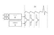
本発明の理解を容易にするために、本発明の例示的な実施形態は、図1に示すような本発明の医療イメージングシステムによって実現されるTEEプロシージャの超音波スキャニング及び画像再構成の見地における改善のために、食道ECGに向けられており、図1に示す本発明の医療イメージングシステムは、(1)超音波トランスデューサ21及びX個の心房電極22(X≧1)を有するTEEプローブ20、(2)Y個の心室電極23(Y≧1)、(3)ECGマシン30、及び(4)超音波マシン40、を有する。 To facilitate understanding of the present invention, exemplary embodiments of the present invention are in terms of ultrasound scanning and image reconstruction of a TEE procedure implemented by the medical imaging system of the present invention as shown in FIG. For improvement, the medical imaging system of the present invention directed to the esophagus ECG and shown in FIG. 1 includes (1) a
図1を参照して、上述したように、TEEプロシージャは、TEEプローブ20が、患者の開いた口に通され、患者の咽喉へ、そして患者の食道Eへ通されることを含む。心臓Hに対する食道Eの近接性のため、心臓Hの腔及び弁は、当分野において知られているように超音波トランスデューサ21によって明確にスキャンされることができる。本発明によれば、TEEプロシージャは、TEEプローブ20上への心房電極22の新しい配置を含み、それにより、心房RA及びLAの電気活動が、心臓Hに対する食道Eの近接性のため、心房電極22によって直接検知されることができる。 Referring to FIG. 1, as described above, the TEE procedure includes passing a
TEEプロシージャは、当分野において知られているように、患者の表面胸部領域上への心室電極23の配置を含み、それにより、心室RV及びLVの電気活動が、当分野において知られているように心室電極23によって直接検知されることができる。 The TEE procedure involves the placement of
各々の心房電極22は、心房ECG信号AEを生成して、ECGマシン30に伝達し、各々の心室電極23は、心室ECG信号VEを生成して、ECGマシン30に伝達し、それにより、ECGマシン30は、当分野において知られているように、図示される正常ECG波形31のようなECG波形を生成する。各々の心房ECG信号AEは、心臓Hの心房RA及びLAによる電気活動を主に示し、各々の心室ECG信号VEは、心臓Hの心室RV及びLVによる電気活動を主に示す。従って、ECGマシン30によって生成される正常ECG波形(例えば図示されるECG波形31)は、ECG波形の心房位相(すなわち心房脱分極及び房室結節遅延)が、心房RA及びLAの直接的な検知から導き出される点において、及びECG波形の心室位相(すなわち心房脱分極及び/又は心室再分極)が、心室RV及びLVの直接的な検知から導き出される点において、最善である。更に、ペースメーカが心室の電気活動ではなく心房の電気活動を強調する信号を取得するために異なる接続を使用するやり方と同様に、異常ECG波形(図1に図示せず)の不整脈の心房位相の存在が、各々の心房ECG信号AEを通じて、より容易に検出される。 Each
本発明のECG信号AE及びVEの利点に基づく心臓ゲーティングの目的において、ECGマシン30は、ハードウェア、ソフトウェア、ファームウェア及び/又は回路モジュールとして、心臓位相モニタ32及び心房不整脈モニタ33を、分離された形で又は既存のモジュール(例えば当分野において知られている自動ECG解析ユニット)に統合される形で、組み込む。 For the purpose of cardiac gating based on the advantages of the ECG signals AE and VE of the present invention, the ECG machine 30 separates the
心臓位相モニタ32は、正常ECG波形の各々の心房位相又は正常ECG波形の各々の心室位相を検出するために、ECG信号AE及びVEの一方又は両方を監視する。指定された(すなわち心房又は心室の)心臓位相の各々の検出から、心臓位相モニタ32は、心臓位相信号CPの形の心臓ゲーティング信号を生成して、超音波マシン40に伝達する。 The
心房位相検出の場合、心臓位相モニタ32は、正常ECG波形の各心房位相を検出する際に、ECG信号AE及びVEの両方を処理し、又は心房ECG信号AEのみを処理し、超音波マシン40に対するスキャニング及び/又は画像再構成トリガ(例えばp波トリガ)として心臓位相信号CPを伝達する。 In the case of atrial phase detection, the cardiac phase monitor 32 processes both the ECG signals AE and VE, or only the atrial ECG signal AE, when detecting each atrial phase of the normal ECG waveform. The cardiac phase signal CP is transmitted as a scanning and / or image reconstruction trigger (eg, a p-wave trigger).
心室位相検出の場合、心臓位相モニタ32は、正常ECG波形の各心室位相を検出する際に、ECG信号AE及びVEの両方を処理し、又は心室ECG信号VEのみを処理し、超音波マシン40に対するスキャニング及び/又は画像再構成トリガ(例えばQRS群トリガ)として心臓位相信号CPを伝達する。 In the case of ventricular phase detection, the cardiac phase monitor 32 processes both the ECG signals AE and VE, or only the ventricular ECG signal VE, when detecting each ventricular phase of a normal ECG waveform. The cardiac phase signal CP is transmitted as a scanning and / or image reconstruction trigger (eg, QRS complex trigger).
心房不整脈モニタ33は、異常ECG波形(例えば、心房細動、心房粗動及び心房頻拍)の心房不整脈位相の存在を検出するために、ECG信号AE及びVEの一方又は両方を監視し、超音波マシン40に不整脈アラーム信号AAの形で心臓ゲーティング信号を伝達する。好適には、心房不整脈モニタ33は、異常ECG波形の心房不整脈位相の存在を検出する際に、心房ECG信号AEのみを監視する。 The atrial arrhythmia monitor 33 monitors one or both of the ECG signals AE and VE to detect the presence of an atrial arrhythmia phase in an abnormal ECG waveform (eg, atrial fibrillation, atrial flutter and atrial tachycardia) A cardiac gating signal is transmitted to the
超音波マシン40は、当分野において知られているような、超音波トランスデューサ21による心臓Hのスキャニングを制御するスキャナ42と、当分野において知られていような、超音波トランスデューサ21から受信される超音波エコー信号USEから心臓Hの超音波画像を画像再構成する画像再構成器43と、を組み込む。実際、超音波トランスデューサ21は、当分野において知られている任意のタイプの超音波トランスデューサ(例えば、2次元又は3次元、線形又は曲線、その他)でありえ、スキャナ42及び画像再構成器43は、超音波トランスデューサのタイプに応じて構造的に構成される。 The
本発明の目的において、スキャナ42及び/又は画像再構成器43は、心臓位相信号CPによってトリガされる及び/又は不整脈アラーム信号AAによってトリガされる、個々のスキャニング及び画像再構成タスクを実行するように構造的に構成される。 For the purposes of the present invention, the
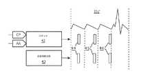
例えば、図2に示すように、スキャナ42は、連続するスキャニング期間SCPにわたってスキャニングタスクを実行するように構造的に構成され、画像再構成器43は、心房位相検出のための心臓位相信号CPによってトリガされる又は不整脈アラーム信号AAによってトリガされる周期的な画像再構成期間IRPの間、画像再構成タスクを実行するように構造的に構成される。正常ECG波形31aの場合、画像再構成期間IRPは、心臓位相信号CPによってトリガされる心房位相の部分(例えばp波のみ)又は全体を含む。異常ECG波形31bの場合、画像再構成期間IRPは、好適には、不整脈アラーム信号AAによってトリガされる心房位相の全体を含む。この目的で、画像再構成器43は、心房不整脈がモニタ33(図1)によって検出されるときはいつでも、不整脈アラーム信号AAが心臓位相信号CPに優先するように、構造的に構成されることができる。 For example, as shown in FIG. 2, the
更に例示として、図3に示すように、スキャナ42は、心房位相検出のために心臓位相信号CPによってトリガされる又は不整脈アラーム信号AAによってトリガされる周期的なスキャニング期間SCPの間、スキャニングタスクを実行するように構造的に構成され、画像再構成器43は、スキャニング期間SPと一致する周期的な画像再構成期間IRPの間、画像再構成タスクを実行するように構造的に構成される。正常ECG波形31aの場合、スキャニング期間SCP及び画像再構成期間IRPは、心臓位相信号CPによってトリガされる心房位相の部分(例えばp波のみ)又は全体を含む。異常ECG波形31bの場合、画像スキャニング期間SCP及び再構成期間IRPは、好適には、不整脈アラーム信号AAによってトリガされる心房位相の全体を含む。この目的で、スキャナ42は、心房不整脈がモニタ33(図1)によって検出されるときはいつでも、不整脈アラーム信号AAが心臓位相信号CPに優先するように、構造的に構成されることができる。 By way of further example, as shown in FIG. 3, the
更なる例として、図4に示すように、心房粗動波形31cは、心室サイクル(すなわちT波)ごとに、QRS群の前に複数の心房サイクル(すなわちF波)を含む。この波形31cの場合、心房電気活動及び心室電気活動は時間的に重なり合っており、心室サイクル当たりの心房サイクルの数が変化することができ、心房サイクルとQRS群の間の位相は、図示されるように、図4Aと図4Bとの間で異なりうる。この目的で、スキャナ42は、不整脈アラーム信号AAによってトリガされる位相のスキャニングタスクを実行するように構造的に構成され、画像再構成器43は、スキャニング位相と一致して画像再構成タスクを実行するように構造的に構成される。より具体的には、図4に示すように、6つの位相φは、当業者によって理解されるように(例えば、多くの心拍にわたって取得されるより小さいサブボリュームからより大きい3D超音波画像を構築することと同様に)、複数心房サイクルにわたる単一の長期間画像を構築して単一の完全な心房サイクルを示すための、各々の心房サイクルの変化するスライスである。 As a further example, as shown in FIG. 4, the
図2−図4の記述から、当業者は、実際に、スキャナ42及び/又は画像再構成器43は、多くのさまざまな動作モードにおいて個々のスキャニング及び画像再構成タスクを実行するように、心臓位相信号CPによってトリガされる及び/又は不整脈アラーム信号AAによってトリガされることができる。 From the description of FIGS. 2-4, those skilled in the art will recognize that the
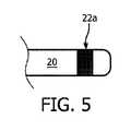
図1に戻って参照すると、実際、各々の心房電極22は、心臓Hの心房の電気活動を直接検知するのに適した構造形態を有することができる。例えば、各々の心房電極22は、当分野において知られているリードの形を有することができ、又は、図5に示すようにTEEプローブ20の周囲に配置される電極リング22aでありうる。更に実際に、複数の心房電極22が、心臓Hの心房の電気活動を直接検知するのに適した態様で、TEEプローブ22上に配置されることができる。例えば、心房電極22は、図6に示すように破線によって示されるTEEプローブ20の長手軸に平行な線形配置50を有することができ、又は図7に示すようにTEEプローブ20の長手軸に対して垂直な円形配置51を有することができる。 Referring back to FIG. 1, in fact, each
更に実際に、1対の心房電極22、又は1対の心房電極22及び心室電極23が、バイポーラECG信号を生成するために利用されることができる。このような対は、ECGマシン30の心臓ゲーティングフィーチャを改善する。より具体的には、電極間のバイポーラ差は、バイポーラ電極対の物理軸に沿って信号振幅を改善し、異なるバイポーラ組み合わせは、心臓のさまざまな部分の信号振幅を改善するために使用されることができ、それにより、電気伝導は、バイポーラ電極対の方向に進む。これは、診断ECGのための複数のECG電極の理由である。 Furthermore, in practice, a pair of
図1−図7を参照して、当業者であれば、速く動く心房位相のシネループを表示するために心臓ゲーティングの目的で使用されることができるTEEプロシージャの間の心房不整脈アラームを含む本発明の多くの利点を理解するであろう。例えば、図4を参照して、複数の心房サイクルにわたる心房脱分極の変化する位相における短いスキャン周期を通じて、心房脱分極の非常に高解像度の画像が生成されることができる。 With reference to FIGS. 1-7, one of ordinary skill in the art will be aware of a book containing an atrial arrhythmia alarm during a TEE procedure that can be used for the purpose of cardiac gating to display a fast moving atrial phase cine loop. Many of the advantages of the invention will be appreciated. For example, referring to FIG. 4, a very high resolution image of atrial depolarization can be generated through a short scan period in the changing phase of atrial depolarization over multiple atrial cycles.
本発明のさまざまな実施形態が図示され記述されているが、当業者によって、ここに記述される本発明の実施形態は例示であり、さまざまな変形及び変更が行われることができ、等価なものは、本発明の真の範囲を逸脱することなくその構成要素と置き換えられることができることが理解される。更に、多くの変更が、その中心範囲を逸脱することなく本発明の教示を適応させるために行われることができる。従って、本発明は、本発明を実施するために企図される最良の形態として開示される特定の実施形態に制限されず、本発明は、添付の特許請求の範囲に入るすべての実施形態を含むことが意図される。 While various embodiments of the present invention have been illustrated and described, the embodiments of the present invention described herein are exemplary by those skilled in the art, and various modifications and changes can be made and equivalents Can be replaced with its components without departing from the true scope of the invention. In addition, many modifications may be made to adapt the teachings of the present invention without departing from its central scope. Accordingly, the invention is not limited to the specific embodiments disclosed as the best mode contemplated for carrying out the invention, but the invention includes all embodiments that fall within the scope of the appended claims. Is intended.
Claims (20)
Translated fromJapanese前記心臓に隣接する前記患者の食道に位置付けられる経食道プローブであって、前記心臓をスキャンするように動作可能な超音波トランスデューサを有し、前記経食道プローブが更に少なくとも1つの心房電極を有し、各心房電極が、前記心臓の心房による電気活動を主に示す心房心電図信号を生成する、経食道プローブと、
患者の表面胸部の領域に取り付けられる少なくとも1つの心室電極であって、各心室電極が、前記心臓の心室による電気活動を主に示す心室心電図信号を生成する、心室電極と、
前記少なくとも1つの心房電極による少なくとも1つの心房心電図信号の生成に応じて及び前記少なくとも1つの心室電極による少なくとも1つの心室心電図信号の生成に応じて、前記心臓の心電図波形を生成する心電図マシンであって、前記心電図マシンは更に、前記心電図波形の周期的な心臓位相期間を示す心臓ゲーティング信号を生成する、心電図マシンと、
前記超音波トランスデューサによる前記心臓の超音波スキャニングに応じて及び前記心電図マシンによる前記心臓ゲーティング信号の生成に応じて、前記心電図の前記周期的な心臓位相期間の少なくとも部分を含む前記心臓の少なくとも1つの超音波画像を再構成する超音波マシンと、
を有する医療イメージングシステム。A medical imaging system for ultrasound imaging of a patient's heart,
A transesophageal probe positioned in the patient's esophagus adjacent to the heart, the ultrasonic transducer being operable to scan the heart, the transesophageal probe further comprising at least one atrial electrode A transesophageal probe, wherein each atrial electrode generates an atrial electrocardiogram signal primarily indicative of electrical activity by the atria of the heart;
At least one ventricular electrode attached to a region of the patient's surface chest, wherein each ventricular electrode generates a ventricular electrocardiogram signal primarily indicative of electrical activity by the heart's ventricles;
An electrocardiogram machine that generates an electrocardiogram waveform of the heart in response to generation of at least one atrial electrocardiogram signal by the at least one atrial electrode and in response to generation of at least one ventricular electrocardiogram signal by the at least one ventricular electrode. The electrocardiogram machine further generates a cardiac gating signal indicative of a periodic cardiac phase period of the electrocardiogram waveform;
In response to ultrasound scanning of the heart by the ultrasound transducer and in response to generation of the cardiac gating signal by the electrocardiogram machine, at least one of the hearts comprising at least a portion of the periodic cardiac phase period of the electrocardiogram. An ultrasound machine that reconstructs two ultrasound images;
A medical imaging system.
前記心臓に隣接して前記患者の食道に位置付けられるように構成される経食道プローブを有し、
前記経食道プローブは、前記心臓をスキャンする超音波トランスデューサと、少なくとも1つの心房電極と、を有し、各心房電極は、前記心臓の心房による電気活動を主に示す心房心電図信号を生成し、
前記経食道プローブは、
(i)前記患者の表面胸部の領域に取り付けられ、前記心臓の心室よる電気活動を主に示す心室心電図信号を生成する少なくとも1つの心室電極、
(ii)前記少なくとも1つの心房電極による少なくとも1つの心房心電図信号の生成に応じて及び前記少なくとも1つの心室電極による少なくとも1つの心室心電図信号の生成に応じて、前記心臓の心電図波形を生成し、前記心電図波形の周期的な心臓位相期間を示す心臓ゲーティング信号を生成する心電図マシン、及び
(iii)前記超音波トランスデューサによる前記心臓の超音波スキャニングに応じて及び前記心電図マシンによる前記心臓ゲーティング信号の生成に応じて、前記心電図の前記周期的な心臓位相期間の少なくとも一部を含む前記心臓の少なくとも1つの超音波画像を再構成する超音波マシン、
と通信するように動作可能である、医療イメージング装置。A medical imaging device for ultrasonic imaging of a patient's heart,
Having a transesophageal probe configured to be positioned in the patient's esophagus adjacent to the heart;
The transesophageal probe includes an ultrasound transducer that scans the heart and at least one atrial electrode, each atrial electrode generating an atrial electrocardiogram signal primarily indicative of electrical activity by the atrium of the heart;
The transesophageal probe is
(I) at least one ventricular electrode attached to a region of the patient's surface chest and generating a ventricular electrocardiogram signal primarily indicative of electrical activity by the heart's ventricles;
(Ii) generating an electrocardiographic waveform of the heart in response to generating at least one atrial electrocardiogram signal by the at least one atrial electrode and in response to generating at least one ventricular electrocardiogram signal by the at least one ventricular electrode; An electrocardiogram machine that generates a cardiac gating signal indicative of a periodic cardiac phase period of the electrocardiogram waveform; and (iii) in response to ultrasound scanning of the heart by the ultrasound transducer and by the electrocardiogram machine. An ultrasound machine that reconstructs at least one ultrasound image of the heart including at least a portion of the periodic cardiac phase period of the electrocardiogram in response to generation of
A medical imaging device operable to communicate with the medical imaging device.
前記心臓に隣接して前記患者の食道内に位置付けられる超音波トランスデューサを使用して、前記心臓をスキャンするステップと、
前記心臓に隣接して前記食道内に位置付けられる少なくとも1つの心房電極を使用して、前記心臓の心房による電気活動を主に示す心房心電図信号を生成するステップと、
前記患者の表面胸部領域に取り付けられる少なくとも1つの心室電極を使用して、前記心臓の心室による電気活動を主に示す心室心電図信号を生成するステップと、
前記少なくとも1つの心房電極による少なくとも1つの心房心電図信号の生成に応じて及び前記少なくとも1つの心室電極による少なくとも1つの心室心電図信号の生成に応じて、前記心臓の心電図波形を生成するステップと、
前記心電図波形の周期的な心臓位相期間を示す心臓ゲーティング信号を生成するステップと、
前記心臓の超音波スキャニングに応じて及び前記心臓ゲーティング信号の生成に応じて、前記心電図波形の前記周期的な心臓位相期間の少なくとも時間セグメントを含む前記心臓の超音波画像を再構成するステップと、
を含む医療イメージング方法。A medical imaging method for ultrasonic imaging of a patient's heart,
Scanning the heart using an ultrasonic transducer positioned in the patient's esophagus adjacent to the heart;
Using at least one atrial electrode positioned in the esophagus adjacent to the heart to generate an atrial electrocardiogram signal primarily indicative of electrical activity by the heart's atrium;
Generating a ventricular electrocardiogram signal primarily indicative of electrical activity by the ventricle of the heart using at least one ventricular electrode attached to the surface chest region of the patient;
Generating an electrocardiographic waveform of the heart in response to generating at least one atrial electrocardiogram signal by the at least one atrial electrode and in response to generating at least one ventricular electrocardiogram signal by the at least one ventricular electrode;
Generating a cardiac gating signal indicative of a periodic cardiac phase period of the electrocardiogram waveform;
Reconstructing an ultrasound image of the heart including at least a time segment of the periodic cardiac phase period of the electrocardiogram waveform in response to the ultrasound scanning of the heart and in response to generation of the cardiac gating signal; ,
A medical imaging method comprising:
Applications Claiming Priority (3)
| Application Number | Priority Date | Filing Date | Title |
|---|---|---|---|
| US201462034194P | 2014-08-07 | 2014-08-07 | |
| US62/034,194 | 2014-08-07 | ||
| PCT/IB2015/055747WO2016020800A1 (en) | 2014-08-07 | 2015-07-30 | Esophageal electrocardiogram for transesophageal echocardiography |
Publications (3)
| Publication Number | Publication Date |
|---|---|
| JP2017526414Atrue JP2017526414A (en) | 2017-09-14 |
| JP2017526414A5 JP2017526414A5 (en) | 2018-07-26 |
| JP6543690B2 JP6543690B2 (en) | 2019-07-10 |
Family
ID=54186235
Family Applications (1)
| Application Number | Title | Priority Date | Filing Date |
|---|---|---|---|
| JP2017503982AExpired - Fee RelatedJP6543690B2 (en) | 2014-08-07 | 2015-07-30 | Esophageal ECG for transesophageal echocardiography |
Country Status (4)
| Country | Link |
|---|---|
| US (1) | US10716537B2 (en) |
| EP (1) | EP3177203B1 (en) |
| JP (1) | JP6543690B2 (en) |
| WO (1) | WO2016020800A1 (en) |
Cited By (1)
| Publication number | Priority date | Publication date | Assignee | Title |
|---|---|---|---|---|
| JP2023553586A (en)* | 2020-10-14 | 2023-12-25 | エヌファレンス,インコーポレイテッド | Non-invasive method for the detection of pulmonary hypertension |
Families Citing this family (6)
| Publication number | Priority date | Publication date | Assignee | Title |
|---|---|---|---|---|
| CA3022806A1 (en)* | 2016-05-03 | 2017-11-09 | Acutus Medical, Inc. | Cardiac mapping system with efficiency algorithm |
| EP3666195A1 (en)* | 2018-12-11 | 2020-06-17 | Koninklijke Philips N.V. | Ultrasound control unit |
| US11011257B2 (en) | 2018-11-21 | 2021-05-18 | Enlitic, Inc. | Multi-label heat map display system |
| CN112472104B (en)* | 2020-12-22 | 2023-03-21 | 深圳市德力凯医疗设备股份有限公司 | Method and system for three-dimensional reconstruction of vascular ultrasonic image based on electrocardiosignal |
| US12136484B2 (en) | 2021-11-05 | 2024-11-05 | Altis Labs, Inc. | Method and apparatus utilizing image-based modeling in healthcare |
| CN116584906A (en)* | 2023-05-31 | 2023-08-15 | 徐州市永康电子科技有限公司 | Vital sign detection method and device based on phase comparison in complex indoor scene |
Citations (3)
| Publication number | Priority date | Publication date | Assignee | Title |
|---|---|---|---|---|
| JPH04176447A (en)* | 1990-11-13 | 1992-06-24 | Toshiba Corp | Ultrasound diagnostic equipment |
| US5343860A (en)* | 1989-02-06 | 1994-09-06 | Arzco Medical Systems, Inc. | Esophageal recording/pacing catheter with thermistor and cardiac imaging transceiver |
| US7349732B1 (en)* | 2003-12-12 | 2008-03-25 | Pacesetter, Inc. | System and method for emulating a surface EKG using internal cardiac signals sensed by an implantable medical device |
Family Cites Families (11)
| Publication number | Priority date | Publication date | Assignee | Title |
|---|---|---|---|---|
| US4817611A (en) | 1986-11-13 | 1989-04-04 | Arzco Medical Electronics, Inc. | Esophageal electrocardiography electrode |
| US5010888A (en)* | 1988-03-25 | 1991-04-30 | Arzco Medical Electronics, Inc. | Method and apparatus for detection of posterior ischemia |
| US6438400B1 (en) | 1993-12-06 | 2002-08-20 | Heska Corporation | Electrode for evaluating cardiac functions via esophagus |
| US5749833A (en) | 1995-08-15 | 1998-05-12 | Hakki; A-Hamid | Combined echo-electrocardiographic probe |
| US5904651A (en) | 1996-10-28 | 1999-05-18 | Ep Technologies, Inc. | Systems and methods for visualizing tissue during diagnostic or therapeutic procedures |
| US5967977A (en) | 1997-10-03 | 1999-10-19 | Medtronic, Inc. | Transesophageal medical lead |
| US20040220471A1 (en)* | 2003-04-29 | 2004-11-04 | Yitzhack Schwartz | Method and device for transseptal facilitation using location system |
| CN100445488C (en)* | 2005-08-01 | 2008-12-24 | 邱则有 | A cavity component for cast-in-place concrete molding |
| US8303505B2 (en)* | 2005-12-02 | 2012-11-06 | Abbott Cardiovascular Systems Inc. | Methods and apparatuses for image guided medical procedures |
| WO2011097312A1 (en)* | 2010-02-02 | 2011-08-11 | C.R. Bard, Inc. | Apparatus and method for catheter navigation and tip location |
| EP2526861A1 (en) | 2011-05-23 | 2012-11-28 | Maastricht University | Non-invasive classification of atrial fibrillation by probabilistic interval analysis of a transesophageal electrocardiogram |
- 2015
- 2015-07-30USUS15/501,093patent/US10716537B2/ennot_activeExpired - Fee Related
- 2015-07-30EPEP15767582.8Apatent/EP3177203B1/ennot_activeNot-in-force
- 2015-07-30JPJP2017503982Apatent/JP6543690B2/ennot_activeExpired - Fee Related
- 2015-07-30WOPCT/IB2015/055747patent/WO2016020800A1/enactiveApplication Filing
Patent Citations (3)
| Publication number | Priority date | Publication date | Assignee | Title |
|---|---|---|---|---|
| US5343860A (en)* | 1989-02-06 | 1994-09-06 | Arzco Medical Systems, Inc. | Esophageal recording/pacing catheter with thermistor and cardiac imaging transceiver |
| JPH04176447A (en)* | 1990-11-13 | 1992-06-24 | Toshiba Corp | Ultrasound diagnostic equipment |
| US7349732B1 (en)* | 2003-12-12 | 2008-03-25 | Pacesetter, Inc. | System and method for emulating a surface EKG using internal cardiac signals sensed by an implantable medical device |
Non-Patent Citations (1)
| Title |
|---|
| 齋藤宣彦, ナースのための心電図テキスト, JPN7018002214, 1 April 1994 (1994-04-01), JP, pages 14 - 23* |
Cited By (1)
| Publication number | Priority date | Publication date | Assignee | Title |
|---|---|---|---|---|
| JP2023553586A (en)* | 2020-10-14 | 2023-12-25 | エヌファレンス,インコーポレイテッド | Non-invasive method for the detection of pulmonary hypertension |
Also Published As
| Publication number | Publication date |
|---|---|
| JP6543690B2 (en) | 2019-07-10 |
| EP3177203B1 (en) | 2018-09-26 |
| EP3177203A1 (en) | 2017-06-14 |
| US10716537B2 (en) | 2020-07-21 |
| WO2016020800A1 (en) | 2016-02-11 |
| US20170215840A1 (en) | 2017-08-03 |
Similar Documents
| Publication | Publication Date | Title |
|---|---|---|
| JP6543690B2 (en) | Esophageal ECG for transesophageal echocardiography | |
| Provost et al. | Electromechanical wave imaging for arrhythmias | |
| Kanai | Propagation of vibration caused by electrical excitation in the normal human heart | |
| CN102523733B (en) | Ultrasonic diagnostic device, image processing device, and image processing method | |
| US8858441B2 (en) | System and method for electromechanical wave imaging of body structures | |
| US20210085284A1 (en) | System and method for electromechanical activation of arrhythmias | |
| US8428687B2 (en) | Systems and methods for matching and imaging tissue characteristics | |
| Provost et al. | A clinical feasibility study of atrial and ventricular electromechanical wave imaging | |
| US20150342571A1 (en) | Medical diagnostic imaging apparatus, medical image processing apparatus, and control method | |
| Provost et al. | Electromechanical wave imaging of normal and ischemic hearts in vivo | |
| WO2014054809A1 (en) | Ultrasonic diagnostic device | |
| JP2017526414A5 (en) | ||
| JP2006068524A (en) | Extraction of abbreviated ultrasonic information useful for inexperienced user of ultrasound | |
| Kvåle et al. | Detection of regional mechanical activation of the left ventricular myocardium using high frame rate ultrasound imaging | |
| Berthon et al. | Mapping biological current densities with ultrafast acoustoelectric imaging: Application to the beating rat heart | |
| CN114748103A (en) | Multi-mode ultrasonic imaging method, device and system in heart cavity | |
| Hollender et al. | Intracardiac acoustic radiation force impulse (ARFI) and shear wave imaging in pigs with focal infarctions | |
| JP2011526191A (en) | Clinical application for measurements derived by electrical tomography | |
| Pernot et al. | Electromechanical imaging of the myocardium at normal and pathological states | |
| Alvarez et al. | 4D cardiac activation wave mapping in in vivo swine model using acoustoelectric imaging | |
| Hsu et al. | Novel acoustic radiation force impulse imaging methods for visualization of rapidly moving tissue | |
| Ling et al. | Myocardial Elastography for Evaluating the Evolution of Strains and Strain Rates in Canine Myocardium After Myocardial Infarction | |
| Vignon et al. | Fast frame rate 2D cardiac deformation imaging based on RF data: what do we gain? | |
| Papangelopoulou et al. | Cardiac Ultrasound Imaging | |
| Rappaport et al. | Detection of the cardiac activation sequence by novel echocardiographic tissue tracking method |
Legal Events
| Date | Code | Title | Description |
|---|---|---|---|
| A521 | Request for written amendment filed | Free format text:JAPANESE INTERMEDIATE CODE: A523 Effective date:20180612 | |
| A621 | Written request for application examination | Free format text:JAPANESE INTERMEDIATE CODE: A621 Effective date:20180612 | |
| A871 | Explanation of circumstances concerning accelerated examination | Free format text:JAPANESE INTERMEDIATE CODE: A871 Effective date:20180612 | |
| A975 | Report on accelerated examination | Free format text:JAPANESE INTERMEDIATE CODE: A971005 Effective date:20180622 | |
| A131 | Notification of reasons for refusal | Free format text:JAPANESE INTERMEDIATE CODE: A131 Effective date:20180712 | |
| A521 | Request for written amendment filed | Free format text:JAPANESE INTERMEDIATE CODE: A523 Effective date:20181011 | |
| A131 | Notification of reasons for refusal | Free format text:JAPANESE INTERMEDIATE CODE: A131 Effective date:20181101 | |
| A601 | Written request for extension of time | Free format text:JAPANESE INTERMEDIATE CODE: A601 Effective date:20190117 | |
| A521 | Request for written amendment filed | Free format text:JAPANESE INTERMEDIATE CODE: A523 Effective date:20190425 | |
| TRDD | Decision of grant or rejection written | ||
| A01 | Written decision to grant a patent or to grant a registration (utility model) | Free format text:JAPANESE INTERMEDIATE CODE: A01 Effective date:20190523 | |
| A61 | First payment of annual fees (during grant procedure) | Free format text:JAPANESE INTERMEDIATE CODE: A61 Effective date:20190617 | |
| R150 | Certificate of patent or registration of utility model | Ref document number:6543690 Country of ref document:JP Free format text:JAPANESE INTERMEDIATE CODE: R150 | |
| R250 | Receipt of annual fees | Free format text:JAPANESE INTERMEDIATE CODE: R250 | |
| LAPS | Cancellation because of no payment of annual fees |